9744480 Whirlpool Pwr Cln DW Tech Sheet
2013-05-09
: Pdf 9744480 - Whirlpool Pwr Cln Dw Tech Sheet 9744480 - Whirlpool Pwr Cln DW Tech Sheet dishwasher may8
Open the PDF directly: View PDF ![]() .
.
Page Count: 2
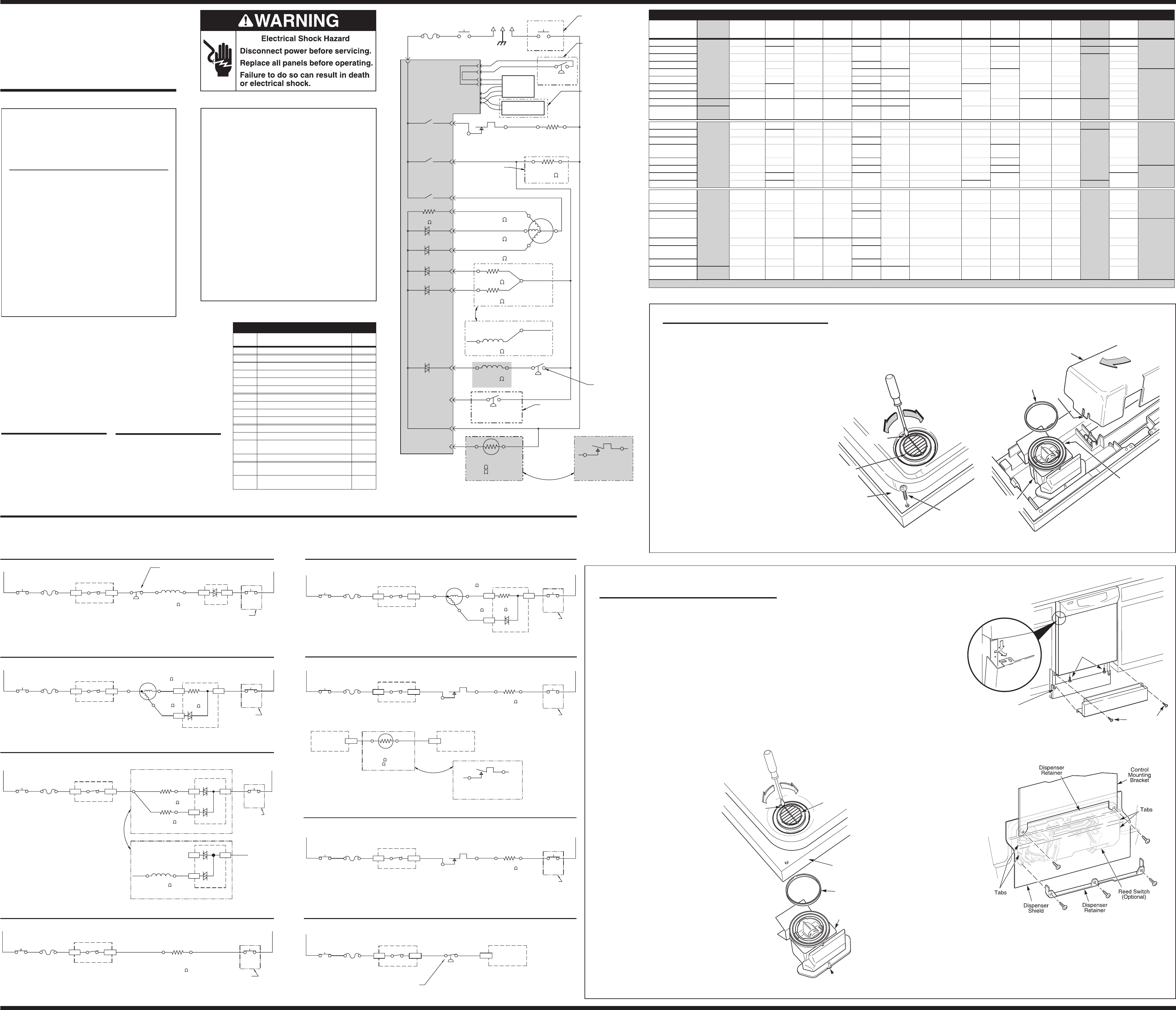
PRECAUTIONS TO BE
OBSERVED BEFORE AND
DURING SERVICING OF
DISHWASHER
A. Even with the door open, there is line voltage at
several points in the console and below the tub.
Therefore, be sure to disconnect the power
supply at the fuse box before replacing a
component.
B. Always check wiring harness and connectors
before any test procedures.
C. Disconnect power supply before touching the
circuit board or re-seating control connectors.
D. Voltage checks are made by inserting probes
beside wires on the connector with the AC power
source applied and the connector blocks plugged
in.
E. Resistance checks are made on components with
the wiring harness disconnected.
Electrostatic Discharge (ESD)
Sensitive Electronics
ESD problems are present everywhere. ESD may
damage or weaken the electronic board. The new
board may appear to work well after repair is
finished, but failure may occur at a later date due
to ESD stress.
■Use an anti-static wrist strap. Connect wrist
strap to green ground connection point or
unpainted metal in the appliance
-OR-
Touch your finger repeatedly to a green ground
connection point or unpainted metal in the
appliance.
■Before removing the part from its package,
touch the anti-static bag to a green ground
connection point or unpainted metal in the
appliance.
■Avoid touching electronic parts or terminal
contacts; handle electronic board by edges only.
■When repackaging failed electronic board in
anti-static bag, observe above instructions.
PART NO. 9744480
NOTE: This sheet contains important
Technical Service Data
FOR SERVICE TECHNICIAN ONLY
DO NOT REMOVE OR DESTROY
LINE 120 V 60HZ
BK
BKT
DOOR SWITCH
3369325
TCO
(TRIP TEMP
DEPENDS ON MODEL;
SEE TABLE)
W
G
USER
INTERFACE
(SEE TABLE)
T
VENT ACTUATOR
600-1800
HI-LIMIT THERMOSTAT
OPENS 77°C-83°C (171°F-181°F)
3371618
ELECTRONIC CONTROL
(SEE TABLE)
(TRIACS AND RELAYS SHOWN)
P6 W-R
P9 BU-BK
P10
N.O.
N.O.
N.O.
R-BK
P3 BU
P5 GY
P4 Y
P2-4 LBU
P2-5 BR
P2-1 O-GY
P7 W-V
P8
K2
K3
K1
RINSE AID
600 - 1800
MAIN WINDING
2.0 - 3.4
DRAIN WINDING
4.2 - 7.0
WASH WINDING
4.2 - 7.0
SENSE RESISTOR
Q6
Q5
Q2
Q3
N.C. OR W-V
PRESSURE SWITCH
(SOIL SENSOR)
3380871
FILL VALVE
695 - 995
(SEE TABLE)
OVERFILL SW.
(SEE TABLE)
BR-W
PUMP & MOTOR
ASSEMBLY
(SEE TABLE)
Y
BU
BU-BK
OPERATING THERMOSTAT
CLOSES 57°C-63°C
(135°F-145°F)
3378083
N.O.
W-V
THERMISTOR
47-53K @ 25°C/77°F
12-13K @ 60°C/140°F
9743158
P2-2 GY-O
T
P2-3 O-BK
DETERGENT
600 - 1800
Q1
W-VW
(W)
DOOR SWITCH
3369325
BU-BK
DUAL WAX
MOTOR
3374501
BU-BK
*
*
*
*
W-V
GY
U
S
ED
O
NLY
O
N“PLA
S
TI
C
TUB MODELS”, OTHERWISE
CONTINUOUS CIRCUIT AND
“W-V” WIRES REMAIN “W”
NUMERIC DISPLAY
(SEE TABLE)
USED ONLY ON
FLOAT (IN
NORMAL POSITION)
CLOSES SWITCH
SOME MODELS,
OTHERWISE OPEN
(SEE TABLE)
HEATER
(WATTAGE DEPENDS
ON MODEL; SEE TABLE)
USED ONLY ON
SOME MODELS,
OTHERWISE OPEN
(SEE TABLE)
800 - 1000
TO BU-BK
SOLENOID
9744335
(O-BK OPEN)
TO LBU
(P2-4)
DET / R.A.
DISPENSER DEPENDS ON MODEL
(SEE TABLE)
USED ONLY ON
SOME MODELS,
OTHERWISE OPEN
(SEE TABLE)
TEMPERATURE SENSOR
WATER
DEPENDS ON MODEL
(SEE TABLE)
P1
RINSE AID SENSOR
9742852
P14 R
P13-1
P13-2
P15 RN.O.
N.O.N.O.
N.O.
N.O.
USED ONLY ON
SOME MODELS,
OTHERWISE OPEN
(SEE TABLE)
(W)
(W)
(W)
(W)
<1
WIRING DIAGRAM
SCHEMATIC SHOWN WITH
DOOR SWITCH AND ALL
OTHER NORMALLY OPEN
CONTACTS OPEN.
FILL
BK T T
P9
BU-BK
P2-5
BR
P7
P8
Q3 TRIAC
ELECTRONIC CONTROL
OVERFILL SW.
BR-W W
DOOR
SWITCH
W-V
(W)
FILL VALVE
695 - 995
TCO
(TRIP TEMP
DEPENDS ON MODEL;
SEE TABLE)
L1
DOOR
SWITCH
K3 RELAY
ELECTRONIC CONTROL
N
USED ONLY ON
USED ONLY ON
USED ONLY ON
PLASTIC TUB
MODELS, OTHERWISE
CONTINUOUS CIRCUIT &
W-V WIRES REMAIN W
PLASTIC TUB MODELS,
PLASTIC TUB MODELS,
OTHERWISE CONTINUOUS
OTHERWISE CONTINUOUS
CIRCUIT & W-V WIRES
CIRCUIT & W-V WIRES
REMAIN W
REMAIN W
N.O. N.O.
FLOAT (IN NORMAL POSITION)
CLOSES SWITCH
WASH / RINSE
BK T T
P10
R-BK
P3 P7
P8
W
DOOR
SWITCH
W-V
(W)
L1
DOOR
SWITCH
K1 RELAY
ELECTRONIC CONTROL
SENSE
RESISTOR
<1
N
P4
Q5 TRIAC
ELECTRONIC CONTROL
PUMP & MOTOR
ASSEMBLY Y
BU
TCO
(TRIP TEMP
DEPENDS ON MODEL;
SEE TABLE)
N.O.
MAIN WINDING
2.0 - 3.4
WASH
WINDING
4.2-7.0
DISPENSER (DETERGENT & RINSE AID)
BK T T
P9 P2-3 P7
P8
W
DOOR
SWITCH
W-V
(W)
L1
DOOR
SWITCH
K3 RELAY
ELECTRONIC CONTROL
Q1 TRIAC
N
P2-4
P2-3 P7
P2-4
Q2 TRIAC
ELECTRONIC CONTROL
BU-BK
Q2 TRIAC
ELECTRONIC CONTROL
SOLENOID
DET / R.A.
800 - 1000
Q1 TRIAC
DUAL WAX MOTOR
RINSE AID
600 - 1800
DETERGENT
600 - 1800
LBU
O-BK
BU-BK LBU
TCO
(TRIP TEMP
DEPENDS ON MODEL;
SEE TABLE)
DISPENSER
DEPENDS ON MODEL
(SEE TABLE)
(OPEN
CIRCUIT)
W-V
(W)
N.O.
BK T T
P9
BU-BK
P8
W
DOOR
SWITCH
W-V
(W)
L1
DOOR
SWITCH
K3 RELAY
ELECTRONIC CONTROL
N
VENT
ACTUATOR
600 - 1800
VENT (USED ONLY ON SOME MODELS,
OTHERWISE OPEN. SEE TABLE)
USED ONLY ON
PLASTIC TUB MODELS,
OTHERWISE CONTINUOUS
CIRCUIT & W-V WIRES
REMAIN W
TCO
(TRIP TEMP
DEPENDS ON MODEL;
SEE TABLE)
N.O.
DRAIN
BK T T
P10
R-BK
P8
W
DOOR
SWITCH
W-V
(W)
L1
DOOR
SWITCH
K1 RELAY
ELECTRONIC CONTROL
N
P3 P7
SENSE
RESISTOR
<1
P5
Q6 TRIAC
ELECTRONIC CONTROL
PUMP & MOTOR
ASSEMBLY
BU
USED ONLY ON
USED ONLY ON
USED ONLY ON
PLASTIC TUB MODELS,
PLASTIC TUB MODELS,
PLASTIC TUB MODELS,
OTHERWISE CONTINUOUS
OTHERWISE CONTINUOUS
OTHERWISE CONTINUOUS
CIRCUIT & W-V WIRES
CIRCUIT & W-V WIRES
CIRCUIT & W-V WIRES
REMAIN W
REMAIN W
REMAIN W
GY
TCO
(TRIP TEMP
DEPENDS ON MODEL;
SEE TABLE)
N.O.
MAIN WINDING
2.0-3.4
DRAIN
WINDING
4.2-7.0
HEAT DRY
BK T T
P6
W-R
P8
W
DOOR
SWITCH
W-V
(W)
L1
DOOR
SWITCH
K2 RELAY
ELECTRONIC CONTROL
N.C. OR
HEATER
15 - 35
(WATTAGE DEPENDS
ON MODEL; SEE TABLE)
HI-LIMIT THERMOSTAT
OPENS 77°C - 83°C
(171°F -181°F)
OPENS 77°C - 83°C
(171°F -181°F)
N
N.O.
TCO
(TRIP TEMP
DEPENDS ON MODEL;
SEE TABLE)
SOIL SENSING
(USED ONLY ON SOME MODELS, OTHERWISE OPEN. SEE TABLE)
PUMP IS ALSO WASHING DURING SENSING PERIODS (SEE WASH / RINSE)
BK T T
P9
BU-BK
P8
L1
DOOR
SWITCH
K3 RELAY
ELECTRONIC CONTROL
N.O.
TCO
(TRIP TEMP
DEPENDS ON MODEL;
SEE TABLE)
PRESSURE
SWITCH
(SOIL SENSOR)
O-GY
N.O.
ELECTRONIC
CONTROL
P2-1
SWITCH CLOSES WHEN
SIGNIFICANT SOILS
ACCUMULATE IN PUMP
WATER HEATING PUMP IS ALSO WASHING DURING WATER HEATING PERIODS (SEE WASH/RINSE)
BK T T
P6
W-R
P8
W
DOOR
SWITCH
W-V
(W)
L1
DOOR
SWITCH
K2 RELAY
ELECTRONIC CONTROL
N.O.
P2-2
GY-O
T
THERMISTOR
47-53K @25°C/77°F
12-13K @60°C/140°F
OPERATING THERMOSTAT
CLOSES 57°C - 63°C
(135°F -145°F)
N
N.C. OR
HEATER
15 - 35
(WATTAGE DEPENDS
ON MODEL; SEE TABLE)
HI-LIMIT THERMOSTAT
WATER
TEMPERATURE SENSOR
DEPENDS ON MODEL
(SEE TABLE)
W-V
(W)
TCO
(TRIP TEMP
DEPENDS ON MODEL;
SEE TABLE)
N.O.
GY-O
W-V
(W)
ELECTRONIC
CONTROL
ELECTRONIC
CONTROL
P7
DISHWASHER CIRCUITS
The following individual circuits are for use in diagnosis. Before starting diagnosis, check the line voltage and check for blown fuses.
KUDG25,
KUDH25 9743991 3378083
(Thermostat
KUDI25, KUDJ25 N/A N/A 9744190 8051314 N/A
KUDM25 9743993
KUDR25,
KUDY25,
KUDX25
9744031
or 9744483
9743451
(110°C/230°F) 9744027 9743994 N/A
9743159
(670/435w PTC,
18-35Ω)
3379372 9744335
(Solenoid) 9743413 9744284
9743158
(Thermistor)
KUDS25 9743995
KUDC25
(BK, WH, BT) 9743154 9742852 9743996 8051311 3380871
KUDC25 (SS) 9743997
KUDV25
(ENERGY STAR) 9744483 9744490 9744151
*DENOTES ENERGY EFFICIENT COMPONENTS. DO NOT SUBSTITUTE.
MODEL SPECIFIC ELECTRICAL COMPONENTS KEY
MODEL
NUMBER
*
ELECTRONIC
CONTROL
TCO WIRING
HARNESS
RINSE AID
HARNESS
RINSE AID
SENSOR
USER
INTERFACE
NUMERIC
DISPLAY HEATER VENT
ACTUATOR
PUMP &
MOTOR
ASSEMBLY
DISPENSER OVERFILL
SWITCH
*
FILL VALVE
PRESSURE
SWITCH
*WATER
TEMPERATURE
SENSOR
1x80x 8271433 3383824 8051314 8274221 N/A
3378083
(Thermostat)
1x77x 3384164 N/A 3370554
1x81x N/A 8051310
1x83x 9744031 or
9744483
3376359
(98°C/208°F)
3383914 N/A N/A 3379320 3379486 (800/500w
PTC, 15-30Ω)3374501
(Dual Wax)
3369067
1x86x 3384165 3383825 8274221
1x89x 3379319 N/A 3380871
1x95x 3383915 3379318 8051311 9743158
(Thermistor)
1x96x 3384096 3383825 3379372
1x97x 9744483 9743451
(110°C/230°F) 9744027 9743154 9742852
9744492 N/A 9743159 (670/435w
PTC, 18-35Ω)
9744335
(Solenoid) 9743413 9744284
1x98x 9744031 or
9744483 9744224 3383825
DP920 8271434 8051124 8274220
3378083
(Thermostat)
DU920 8051313
SUD6000 8051460
N/A
DU925, IJU586,
DU1000 9744031 or
9744483
3376359
(98°C/208°F)
8271433 N/A N/A 8051124 N/A 3379486 (800/500w
PTC, 15-30Ω)
N/A 8051314 3374501
(Dual Wax) 3369067 3370554
DU929 8051460 8051313
GU940, IJU588 8051127 8051312 9743158
(Thermistor)
GU980 3383914 8051133 8051311 3380871
GU990 3383915 3379372 8274221
ELECTRONIC CONTROL CONNECTOR PINS
PIN
NUMBER DESCRIPTION WIRE
COLOR
P1 Ribbon Cable To User Interface —
P2-1 Pressure Switch (Soil Sense) O-GY
P2-2 Thermistor/Thermostat GY-O
P2-3 Detergent Dispenser O-BK
P2-4 Rinse Aid Dispenser LBU
P2-5 Fill Valve BR
P3 Motor Main Winding BU
P4 Motor Aux Winding - Wash Y
P5 Motor Aux Winding - Drain GY
P6 Switched L1 to Heater W-R
P7 AC Neutral W-V
P8 L1 T
P9 Switched L1 to Vent, Fill Valve,
Dual Dispenser, & Pressure Switch BU-BK
P10 Switched L1 to Motor Common R-BK
P13 Ribbon Cable to User Interface for
Optional Rinse Aid Empty Light —
P14
P15 Optional Rinse Aid Sensor RED
MANUFACTURED UNDER ONE OR MORE OF THE
FOLLOWING CANADIAN PATENTS:
1,159,749
1,159,750
1,159,751
1,162,463
1,185,646
1,278,462
1,288,666
1,288,667
1,288,668
DES.67.168
OTHER PATENTS PENDING
WHIRLPOOL CORP.- Rd.1990
MANUFACTURED UNDER ONE OR MORE OF THE
FOLLOWING UNITED STATES PATENTS:
3,951,683
4,134,003
4,301,882
4,319,598
4,319,599
4,350,306
4,418,868
4,449,765
4,693,526
4,732,323
4,732,431
4,746,177
4,765,697
4,776,620
4,805,647
4,822,241
4,834,125
4,848,382
4,927,033
4,991,611
5,005,740
5,018,550
5,031,649
5,031,651
5,033,659 5,039,828 5,069,360
DES.320,487 DES.320,488 DES.320,489 DES.314,256
OTHER PATENTS PENDING
SPECIFICATIONS
Electrical Supply:
(Under load) 60 Hz, 120 VAC.
Supply Water Flow Rate:
Tofill1.9liters(2quarts)in
27 seconds, 120 PSI maximum,
20 PSI minimum.
Supply Water Temperature:
49°-71°C(120°to 160°F)
(Before starting a cycle, run
water from sink faucet until hot.)
Water Charge:
8.3 liters (2.2 gallons) / fill approx.
Lower Spray Arm Rotation: 25 to 40 rpm.
Upper Spray Arm Rotation: 18 to 30 rpm.
REPAIR KITS
nVinyl Rack Patch Kit No. 676453
nTine Tip Kit No. 675679
FOR STAINLESS STEEL TUB
MODELS ONLY:
REMOVING THE ARTICULATED VENT ASSEMBLY
1. Disconnect electrical power from dishwasher.
2. Open dishwasher door. Remove four (4) screws at the top of
stainless steel inner door panel to loosen console. Hold
console to prevent strain on wiring.
3. Close door and pull top of console away from door.
Disconnect ribbon cable and rinse aid sensor connectors
from console circuit board.
4. Lift console up to disengage bottom tabs from door frame.
Set console aside.
5. Disconnect electrical connectors from wax motor terminals.
Open door and place your hand under the vent assembly to
support it when it is released.
6. Insert the end of a screwdriver into the notch in the vent louver.
Push counter-clockwise to rotate louver approximately 1/8 turn
to release it. See Figure 3.
7. Retain the vent louver and seal ring for later reinstallation.
REINSTALLING THE ARTICULATED
VENT ASSEMBLY
1. Place seal ring in seal ring groove of
vent assembly.
2. Close dishwasher door. Align
the plastic post at the top of vent
assembly with the notch in door
frame.
3. Move vent assembly into position so
seal ring contacts stainless steel inner
door panel.
4. Open door and place vent louver over
vent assembly, making sure it is seated.
Turn louver clockwise by hand to engage
vent assembly.
5. Insert the end of a screwdriver into the notch
in the vent louver. Push clockwise to rotate the
louver approximately 1/8 turn to lock it in position.
See Figure 3.
6. Reinstall console by first engaging bottom tabs
into door frame and control mounting bracket,
making sure that the latch link is properly inserted
into the latch ever as the console is rotated into the
proper position. Reconnect ribbon cable and rinse
aid sensor connectors to console circuit board.
7. Press top of console against door and attach the
console by reinstalling the four (4) screws at the top
of the stainless steel inner door panel.
8. Reconnect electrical power to dishwasher.
Counter-Clockwise
to Release
Inner
Door
Panel
Seal
Ring
Vent
Assembly
Plastic Post
Clockwise
to Lock
Vent
Louver
Notch
Figure 3
REMOVING THE DETERGENT DISPENSER
1. Disconnect electrical power from dishwasher.
2. With dishwasher door closed, loosen the two (2) toe panel
screws, but do not remove them.
3. Remove two (2) screws from top of access panel. Pull top of
access panel away from door, lift up and remove. See Figure 4.
4. Remove two (2) screws from bottom of outer door panel.
5. Refer to detail inset in Figure 4. Slide outer door panel
downward until slots in door panel align with slots in
door frame, then pull door panel straight off.
6. Disconnect electrical connectors from terminals of
dispenser solenoid.
7. Referring to Figure 5, remove the two (2) metal dispenser
retainers: First remove the two (2) outer edge screws from
the control mounting bracket and detergent dispenser shield.
Next remove the three (3) screws from the bottom retainer,
releasing it. Reach under the detergent dispenser shield to
remove the remaining screw from the center hole of the
upper retainer. Set the retainers aside for later reinstallation.
Toe Panel
Screw (2)
Outer
Door
Panel
Outer
Door
Panel
Outer Door
Panel Screws
Access
Panel Screws
Door
Frame
Access Panel
Toe Panel
Console
Figure 4
Figure 5
8. With dishwasher door open, reach under and press
the tabs at each end of dispenser to release it. Lift
dispenser up from inner door panel to remove it.
9. Remove blue rinse aid cap to take note of
rinse aid dial setting, then replace cap.
INSTALLING THE DETERGENT
DISPENSER
1. Remove the blue rinse aid knob.
Using a coin, turn the dial to setting
used previously, then replace knob.
2. Snap dispenser into place from
inside the dishwasher. Close the
door. Referring to Figure 5, replace
the metal dispenser retainers. Install
one (1) screw each into the center
hole of each retainer. Place two (2)
screws in the remaining holes of
the lower retainer and tighten. Insert
the two (2) remaining screws through
the upper dispenser retainer and
dispenser shield, and tighten. Make
sure that the detergent dispenser shield
is properly installed and captured by the
top dispenser retainer.
3. Connect electrical connector to
detergent dispenser solenoid, in any order.
Connect rinse aid dispenser indicator harness
to reed switch, if applicable.
4. Refer to detail inset in Figure 4. Align slots in outer
door panel with slots in door frame, push door panel
in and slide upward. Install two (2) screws at bottom
of outer door panel. Be sure that door insulation is
installed in unit.
5. Slide access panel slots down over toe panel
screws. Press top of access panel against dish-
washer and tighten two (2) screws at top of panel.
6. Tighten toe panel screws.
7. Reconnect electrical power to dishwasher.
FOR PLASTIC TUB MODELS ONLY:
ARTICULATED VENT ASSEMBLY &
ELECTRONICS COVER REMOVAL
1. Disconnect electrical power from dishwasher.
2. Refer to Figure 1. Open dishwasher door and insert the
end of a screwdriver into the notch in the vent louver.
Push counter-clockwise to rotate louver approximately
1/8 turn to release it. Remove louver and set aside for
later reinstallation.
3. Remove eight (8) screws around perimeter of the
inner door panel and remove panel. See Figure 1.
4. To remove the vent assembly, refer to Figure 2 and
disconnect two (2) electrical harness wire leads from
wax motor terminals. Lift out the vent assembly,
retaining the seal ring for later reinstallation.
5. To access electronic controls, press in on snap tab at
end of electronics cover to release, then lift cover up at
tab end as you slide cover out. See Figure 2.
ARTICULATED VENT ASSEMBLY &
ELECTRONICS COVER REINSTALLATION
1. Reinstall electronics cover by sliding it into position
above controls and pressing down till snap tab holds it
in place. (Figure 2 shows cover removal.)
2. Reinstall the vent assembly. Refer to Figure 2 and
reconnect two (2) electrical harness wire leads to the
wax motor terminals. Place seal ring in seal ring groove
of vent assembly, and lower vent assembly into place.
3. Reinstall inner door panel. Align it in place over the vent
assembly, and reinstall eight (8) screws around the
inner door panel perimeter. See Figure 1.
4. Align vent louver over vent assembly, and turn louver
clockwise by hand to engage vent assembly.
5. Insert the end of a screwdriver into the notch in the vent
Inner
Door Panel
Counter-Clockwise
to Release
(8)
Inner Door Panel
Screws
Clockwise
to Lock
Vent
Louver
Notch
Figure 1
louver. Push clockwise to rotate louver approximately
1/8 turn to lock it in position. See Figure 1.
6. Reconnect electrical power to dishwasher.
Seal
Ring Snap
Tab
Harness Wire
Leads Location
Electronics
Cover
Vent
Assembly
Figure 2
FOR SERVICE TECHNICIAN'S USE ONLY FOR SERVICE TECHNICIAN'S USE ONLY FOR SERVICE TECHNICIAN'S USE ONLY PAGE 1
FOR SERVICE TECHNICIAN'S USE ONLY FOR SERVICE TECHNICIAN'S USE ONLY FOR SERVICE TECHNICIAN'S USE ONLY
INTERVAL 37 36 35 34 33 32 31 30 29 28 27 26 25 24 23 22 21 15 14 13 12 11 10 9 8 7 6
POTS & PANS / ANTI-BACTERIA
HEAVY / SOAK & SCRUB
54321 038
39
4041
HEAVY SOIL
2:00
0:05
[6:00]
[TH]
0:05
2:00
0:05
6:00
0:00
2:00
2:00
1:00
1:30
7:30
2:00
2:00
2:00
2:00
2:00
2:00
2:00
0:05
[6:00]
[TH]
0:05
2:00
0:05
1:55
TH
5:00
0:05
0:05
0:05
0:05
TH
6:00
6:00
6:00
6:00
2:00
0:05
[6:00]
[TH]
0:05
2:00
2:00
1:00
1:30
7:30
2:00
2:00
2:00
2:00
2:00
0:05
[6:00]
[TH]
0:05
2:00
0:05
0:05
TH
6:00
6:00
6:00
6:00
2:00
0:05
[6:00/4:00]
0:05
2:00
2:00
1:00
1:30
7:30
2:00
2:00
2:00
2:00
2:00
0:05
[6:00]
0:05
2:00
0:05
0:05
TH
6:00
6:00
6:00
6:00
97:00
PRE-WASH / PRE-RINSE PRE-RINSE MAIN WASH RINSE FINAL RINSE DRY
20 19 18 17 16
0:25
1:00
0:05
0:05
0:05
PURGE
PERIOD 1 PERIOD 2 PERIOD 3 PERIOD 4 (a) PERIOD 4 (b) PERIOD 5 PERIOD 6
4243444546
47
48
49
INTERVAL TIME (min:sec)
MEDIUM SOIL
LIGHT SOIL OR NON-SENSOR MODEL
85 83 83 83 83 83 81 79 79 79 79 79 77 75 75 75 73 67 67 62 62 62 60 58 58 52 46 46 44 42 42 42 41 40 32 32 30 24 22 16 14 8 6
6:00
6:00
2:00
0:05
97:00
87:00
NUMERIC CYCLE TIME DISPLAY
92:00
INTERVAL TIME (min:sec)
92:00
82:00
NORMAL (ENERGY STAR “HEAVY”)
90:00/88:00
INTERVAL TIME (min:sec)
70:00
86:00/84:00
71:30/74:30
(W1=WASHING, R1=RINSING, D1=DRYING)
CYCLE PROGRESSION INDICATORS
RINSE CYCLE
STATUS INDICATORS
OUTPUT LOADS
ADD-A-DISH
WATER HEATING
SENSING
SANI COMPLETE
CLEAN
MOTOR
WASH
DRAIN
FILL
DETERGENT DISPENSER
RINSE AID (DET/R.A.) DISPENSER
VENT
HEATER
NOTE 13
NOTE 20
NOTE 16
NOTE 17
NOTE 17
0:05
6:00
0:00
0:05
1:55
TH
2:00
0:05
2:00
2:00
0:05
0:05
6:00
6:00
2:00
2:00
0:05
0:05
6:00
6:00
0:05
4:00
2:00/7:00
2:00
0:05
1:55
TH
2:00
0:05
4:00
80 78 76 74 72 70 70 70 68 62
78 76 76 76 76 74 72 72 72 72 70 68 68 68 66 62 62 62
78 78 78 78 74 74 74 74 60 58 58 52 46 46 44 42 42 42 41 40 32 32 30 24 22 16 14 8 6
44 42 42 42 41 40 32 32 30 24 22 16 14 86
44
46 46 46 45 45
46 46
-- -- -- -- -- --
4848
50/55*
66 --
--
59
62 52 52
62 62 62
62 52 52
50 48 48 48 46
50 48 48 48 46
60 58 58 52
--
R1 R1 R1 R1 R1 R1 R1 R1 R1 R1
R2 R2 R2 R2 R2
R3 R3
2:00
50
2:00
1:00
1:30
7:30
2:00
2:00
2:00
2:00
2:00
0:05
0:05
2:00
0:05
0:05
TH
6:00
6:00
6:00
6:00
2:00
1:30
4:30
2:00
2:00
2:00
2:00
2:00
0:05
[6:00]
0:05
2:00
0:05
0:05
TH
6:00
6:00
6:00
6:00
2:00
2:00
2:00
2:00
0:05
[4:00]
0:05
2:00
0:05
0:05
0:25
1:00
0:05
0:05
0:25
1:00
0:05
0:05
0:05
0:05
WATER MISER/LOW ENERGY/SHORT/CRYSTAL-CHINA
78:00
INTERVAL TIME (min:sec)
63:30
68:00
CHINA (ENERGY STAR “NORMAL”)
74:00
INTERVAL TIME (min:sec)
59:30
64:00
QUICK WASH/QUICK GLASS
29:30
INTERVAL TIME (min:sec)
25:30
RINSE
14:00
INTERVAL TIME (min:sec)
10:00
2:00
1:30
2:30
2:00
0:05
0:05
TH
0:25
1:00
0:05
0:05
0:05
72 70 70 70 70 68 66 66 66 64 58 58 58 44 42 42 42 41 40 32 32
56 54 54 48 46 46
68 66 66 66 66 64 62 62 62 60 54 54 52 50 50 44 42 42
0:05
6:00
2:00
0:05
1:55
TH
2:00
0:05
2:00
2:00
0:05
0:05
6:00
2:00
42 42 42 41 41 38 38 38 37 32 32
30 24 22 16 14 8 6
30 24 22 16 14 8 6
2:00
2:00
0:05
0:05
6:00
2:00
46 46 46 45 45
40
0:05
6:00
2:00
0:05
1:55
2:00
0:05
0:05
6:00
2:00
0:05
1:55
2:00
0:05
22 20 20 20 18 12 12
2:00
0:05
[4:00]
0:05
2:00
26 24 24 24 24
64 422
[6:00]
10 8 888
66 522689910 10 10
(W1=WASHING, R1=RINSING, D1=DRYING)
CYCLE PROGRESSION INDICATORS
W. MISER/LOW ENERGY/SHORT, CHINA, QUICK WASH/QUICK GLASS
W1 W1 W1 W1 W1 W1 W1 W1 W1
W2 W2 W2 W2
W1
W2
W1
W2
W1
W2
W3 W3 W3 W3
W1
W2 R1 R1 R1 R1 R1 R1 R1 R1 R1
R1 R1 R1 R1 R1
R1
R2 R2 R2
R1 R1 R1
R2 R2 R2
R2 R2
R3 R3 R3R3 R3
R1
(W1=WASHING, R1=RINSING, D1=DRYING)
CYCLE PROGRESSION INDICATORS
POTS&PANS/ANTI-BACTERIA, HEAVY/SOAK&SCRUB, NORMAL
W1 W1 W1 W1 W1 W1 W1 W1 W1 W1
W2 W2 W2 W2 W2
W1 W1 W1 W1 W1
W2 W2 W2 W2 W2
W1
W2
W1
W2
W1
W2
W1
W2
W3 W3 W3 W3 W3 W3
W1
W2
W3W3W3W3
R1R1R1R1R1R1 R1R1R1R1R1R1
R2
R1
R2
R1
R2
R1
R2
R1
R2
R1
R2
R1
R2
R1
R2
R3R3R3R3R3
D1 D1 D1 D1
D2
D1
D2
D1
D2
D1
D2
HEAVY SOIL
MEDIUM SOIL
LIGHT SOIL OR NON-SENSOR MODEL
HEAVY SOIL
MEDIUM SOIL
LIGHT SOIL [SEE NOTE 2A]
LIGHT SOIL OR NON-SENSOR MODEL
NUMERIC CYCLE TIME DISPLAY
NUMERIC CYCLE TIME DISPLAY
MEDIUM SOIL
LIGHT SOIL OR NON-SENSOR MODEL
NUMERIC CYCLE TIME DISPLAY
MEDIUM SOIL
LIGHT SOIL OR NON-SENSOR MODEL
NUMERIC CYCLE TIME DISPLAY
MEDIUM SOIL
LIGHT SOIL OR NON-SENSOR MODEL
NUMERIC CYCLE TIME DISPLAY
MEDIUM SOIL
LIGHT SOIL OR NON-SENSOR MODEL
NUMERIC CYCLE TIME DISPLAY
NOTE 15
NOTE 14
NOTES
NOTE 11
NOTE 19
NOTE 11
NOTE 19
NOTE 11
NOTE 12
NOTE 11
NOTE 11
NOTE 11
NOTE 11
-- -- -- -- --
NOTE 1
LIGHT SOIL [SEE NOTE 2A]
LIGHT SOIL [SEE NOTE 2B]
3
18
19
1
3
18 4
19
NOTES NOTES NOTES NOTES NOTES NOTES
5
19
67
77787
18 19
1
18
19 19
18181818 18 21212121 21 21
10 10 20 20
109
20
*
*
*
*
*
*
W1
W1
W1
W2
W1
W2
W3
D1 D1 D1 D1
D2
D1
D2
D1
D2
D1
D2
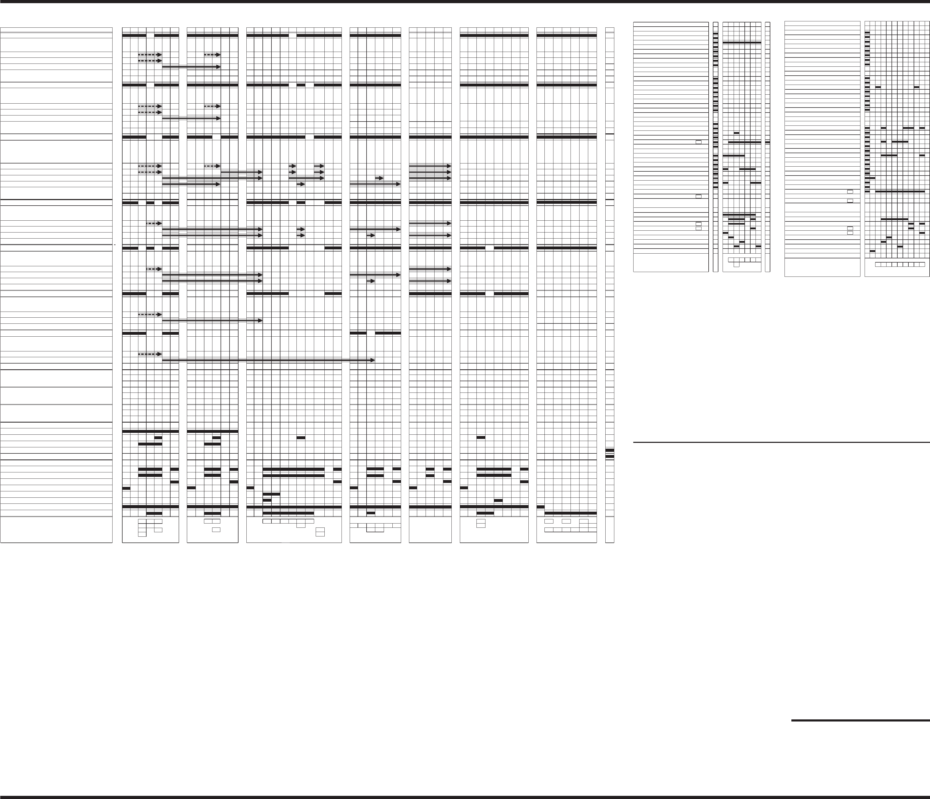
COMMON CYCLE TIME CHART
INTERVAL 11 76543 0
S
T
A
POTS & PANS/ANTIBACTERIA
N
NORMAL
D
W. MISER/SHORT
B
CHINA
Y
QUICK WASH/QUICK GLASS
RINSE CYCLE
SUPER SCRUB
W. HEAT/HIGH TEMP
NO HEAT DRY/ENERGY SAVER DRY
FAVORITE CYCLE SET
WATER HEATING
SANI COMPLETE/SANITIZED
CLEAN
VENT
MOTOR
WASH
DRAIN
FILL VALVE
DETERGENT DISP (n/a)
RINSE AID (DET/R.A.) DISPENSER
HEATER
SENSING
ADD-A-DISH
SOAK&SCRUB
SANI RINSE
DELAY 4-6 HR
DELAY 2-4 HR
DELAY 0-2 HR
NOTES
LOCKOUT
21
W1 - WASHING
W2
W3
R1 - RINSING
R2
R3
D1 - DRYING
D2
NUMERIC DISPLAY
INTERVAL TIME (min:sec)
0:10
0:02
0:05
2:00
88 32110
0:03
10 98
CYCLE BUTTON LIGHTS
OPTION BUTTON LIGHTS
CANCEL DRAIN
STATUS LIGHTS
RINSE AID EMPTY
456789
0:02
0:05
0:02
0:05
0:05
1:00
S
T
A
N
D
B
Y
S
T
A
N
D
B
Y
S
T
A
N
D
B
Y
BAR GRAPH
222222222
NOTE 2
NOTE
NOTE
3
3
NOTE 1
DIAGNOSTICS CYCLE - STAINLESS STEEL MODELS
INTERVAL 8 76543 0
S
T
A
POTS & PANS
N
NORMAL
D
W. MISER/L. ENERGY
B
CHINA
Y
QUICK WASH
RINSE CYCLE
POWER SCOUR
W. HEAT/HI TEMP
NO HEAT DRY/AIR DRY
FAVORITE CYCLE SET
WATER HEATING
SANI COMPLETE/SANITIZED
CLEAN NOTE 2
VENT (disp, fill, soil enable)
MOTOR
WASH DIRECTION
DRAIN DIRECTION
FILL
DETERGENT DISPENSER
RINSE AID DISPENSER
HEATER
2
SENSING
ADD-A-DISH
HEAVY
SANI RINSE
CANCEL DRAIN
DELAY 4-6 HR
DELAY 2-4 HR
DELAY 0-2 HR
4
NOTES
NOTE
NOTE
LOCKOUT
21
WASHING (W1)
W2
W3
RINSING (R1)
R2
R3
DRYING (D1)
D2
NUMERIC CYCLE TIME DISPLAY
INTERVAL TIME (min:sec)
2:00
2:00
TH
2:00
0:05
2:00
6:00
88 14 8 8 612 10 10
0:03
NOTE 1
3
3
22222
CYCLE BUTTON LIGHTS
OPTION BUTTON LIGHTS
STATUS LIGHTS
DIAGNOSTICS CYCLE - PLASTIC TUB MODELS
Pressing the following option keys in the sequence shown will either
start the Diagnostics Cycle or turn on the Rapid Advance feature for
customer selectable cycles:
HI TEMP WASH, AIR DRY, HI TEMP WASH, AIR DRY
or
POWER SCOUR, AIR DRY, POWER SCOUR, AIR DRY
(HI TEMP WASH = HIGH TEMP WASH = WATER HEAT)
(POWER SCOUR = SUPER SCRUB)
(AIR DRY = ENERGY SAVER DRY = NO HEAT DRY)
If the sequence is entered after starting a cycle, the Rapid Advance
feature is turned on, which allows the operator to manually advance
the currently running cycle, interval by interval, by pressing the Pots
& Pans/Antibacteria or Heavy/Soak & Scrub key.
If the above key sequence is entered with the dishwasher in
Standby, the Diagnostics Cycle is started. The Diagnostics Cycle for
stainless steel tub models is different than the Diagnostics Cycle for
plastic tub models (see time charts) but the entry sequence is the
same. The operator can advance either cycle, interval by interval, by
pressing the Pots & Pans/Antibacteria or Heavy/Soak & Scrub key.
(DIAGNOSTICS) NOTE 1 – Numeric Cycle Time Display
For plastic tub models with time displays, the display shows the
current cycle time remaining in the diagnostics cycle (in minutes).
For stainless steel tub models with numeric time displays, the
display simply shows the “Interval Number” of the currently
executing interval.
(DIAGNOSTICS) NOTE 2 – Thermostat/Thermistor Detection
To help identify whether a thermostat or thermistor is installed
in the dishwasher, the Clean light is only illuminated in intervals 1-6
of the plastic tub Diagnostics Cycle and 1-9 of the stainless tub
Diagnostics Cycle if a thermostat is installed. This determination is
based on the resistance detected on the temperature sensor line.
Because the resistance limits used by the control are close to the
thermistor resistance at room ambient, this indicator is only reliable
if warm water is in the dishwasher.
(DIAGNOSTICS) NOTE 3 – Wash and Drain Motor Phase
Windings
The wash and drain phase winding outputs are only “on” while the
motor is starting in the respective mode. Once the control has
determined that the motor started properly, the phase winding
output is turned “off”.
(DIAGNOSTICS) NOTE 4 – Thermal Hold
This thermal hold only occurs in the Plastic Tub Diagnostics Cycle,
the setpoint temperature for this thermal hold is 60°C/140°F and the
default time limit is 1 hour.
RAPID ADVANCE SERVICE FEATURE AND DIAGNOSTICS CYCLES (above)
COMMON CYCLE TIME CHART (above)
The common cycle time chart describes the operation of all possible
cycles, options, display indicators, & sensor features for the
electronic dishwasher models that use this tech sheet. The cycles,
options, display indicators, & sensor features shown in the time chart
are not all available on every model. Cycles and options execute the
same way on all the models with the exception of a few model
specific timing changes described in notes 1, 2, and 20.
The solid bar on the time chart for each cycle shows the intervals
used by that cycle (EXAMPLE: Interval 47 is not used in Pots &
Pans). The “Interval time” on the time chart specifies the duration of
each interval for each cycle.
Cycles all assume at first that a worst case (Heavy or Medium) soil is
on the dishes. Each cycle then determines the true soil level based
on soil sensor inputs received during the Pre-Wash and/or Pre-Rinse
sense intervals:
nHEAVY SOIL - Soil sensor tripped in intervals 48, 47, or 46,
and again in intervals 41 or 40
nMEDIUM SOIL - Soil sensor tripped in intervals 48, 47, or 46,
but not in intervals 41 or 40
nLIGHT SOIL - Soil sensor did not trip in intervals 48, 47, or 46
(cycle skips sense intervals 41 & 40)
Each cycle skips certain intervals based on the true soil level. The
arrows on the time chart show which intervals are skipped.
(EXAMPLE: Pots & Pans cycle skips intervals 45 through 40 when
light soil is detected). See notes 3, 4, 5, and 6 for more details. The
time chart also shows a maximum cycle time estimate for each soil
level (EXAMPLE: 97:00 minutes for Pots & Pans cycles with heavy
soil). These estimates do not include time spent in thermal hold
intervals.
During thermal hold (“TH”) intervals, cycle timing pauses and the
dishwasher washes and heats until the water reaches a setpoint
temperature or a default time limit elapses. See notes 4, 6, 8, and 9
for more details.
Models without a soil sensor will never detect a sensor trip in
intervals 48, 47, or 46 and will always run the light soil version of
each cycle (assuming no options are selected).
The Water Heat/High Temp/High Energy and Power Scour/Super
Scrub options force certain cycles to run no less than the medium
soil version of the cycle (regardless of soil sensor presence or input).
See notes 18 and 19.
For models that have a thermostat, instead of a thermistor, the
thermal hold and thermal cap temperatures specified in this
document will all default to the trip point of the thermostat.
NOTE 1 – Timing Exceptions for Normal Cycle on Stainless Steel
Tub Mo d e l s
For the Normal cycle on stainless steel tub models, the default time
for Pre-Wash sense interval 48 is changed from 6:00 minutes to 4:00
minutes and the duration of Main Wash interval 29 is changed from
2:00 minutes to 7:00 minutes. The cycle time displayed by numeric
display models in interval 29 is adjusted accordingly.
NOTE 2 – Timing Exceptions for the Light Soil Version of the
Normal, Water Miser, & China Cycles on Certain Models
To use less water and/or simulate past production cycles, the
intervals skipped for the Light Soil version of the cycle are different
for some models.
A. Special Light Soil version of Normal and Water Miser cycles for
models: 1x83x, 1x86x, 1x89x, 1x95x, & 1x96x
B. Special Light Soil version of China (Energy Star “Normal”) cycle for
models: 1x83x, 1x86x, 1x89x, 1x95x, 1x96x, KUDV25 (Energy Star)
NOTE 3 – Pre-Wash/Pre-Rinse Sensing Intervals 48 and 47
The dishwasher suspends cycle timing in each of these intervals and
washes until a soil sensor trip is detected or a default time limit
elapses. The default time for each interval is shown in brackets on
the time chart as the “Interval Time” for the interval. The control heats
interval 47 but not interval 48. The heater is turned off in interval 47 if
the water temperature reaches 60°C/140°F. When a soil sensor trip is
detected in either interval, the cycle jumps immediately to interval 45
and proceeds with the Heavy or Medium Soil versions of the cycle
(until sense interval 41). If the default time limit elapses without a soil
sensor trip, the cycle proceeds with the Light Soil version of the cycle.
NOTE 4 – Pre-Wash/Pre-Rinse Thermal Hold/Sensing Interval 46
This thermal hold interval only occurs in Pots & Pans/Antibacteria
and Heavy/Soak & Scrub cycles. The thermal hold setpoint
temperature is 57°C/135°F and the default time limit 25:00 minutes.
This interval is also a sensing interval. If a soil sensor trip is detected,
the cycle jumps immediately to interval 45 and proceeds with the
Heavy or Medium Soil version of the cycle (until sense interval 41). If
the thermal hold reaches its setpoint temperature or the thermal hold
default time limit expires without a soil sensor trip, the cycle
proceeds with the Light Soil version of the cycle.
NOTE 5 – Pre-Rinse Sensing Interval 41
The dishwasher suspends cycle timing and washes and heats until a
soil sensor trip is detected or a default interval time limit elapses. The
default time for this interval is shown in brackets on the time chart as
the “Interval Time” for the interval. The heater is turned off in this
interval if the water temperature reaches 60°C/140°F. When
a soil sensor trip is detected in this interval, the cycle jumps
immediately to interval 39 and proceeds with the Heavy Soil version
of the cycle. If the default time limit elapses without a soil sensor trip,
the cycle proceeds with the Medium Soil version of the cycle.
NOTE 6 – Pre-Rinse Thermal Hold/Sensing Interval 40
This thermal hold interval only occurs in Pots & Pans/Antibacteria and
Heavy/Soak & Scrub cycles, and only occurs if the thermal hold at
interval 46 failed to reach temperature due to a soil sensor trip in
interval 46 or 48. The setpoint temperature for this thermal hold is
57°C/135°F and the default time limit 20:00 minutes. This interval is
also a sensing interval. Upon detecting a soil sensor trip, the cycle
jumps immediately to interval 39 and proceeds as a Heavy Soil
cycle. If this thermal hold reaches its setpoint temperature or the
thermal hold default time limit expires without a soil sensor trip, the
cycle proceeds as a Medium Soil cycle.
NOTE 7 – Thermally Capped Heated Wash Intervals
For intervals 32-35 of the Normal, Water Miser/Low Energy/
Short/Crystal-China, China, and Quick Wash/Quick Glass cycles, the
heater is turned off if the water reaches 60°C/140°F. For interval 30 of
the Pots & Pans/Antibac cycle, the heater is turned off if the water
temperature reaches 66°C/150°F.
NOTE 8 – Main Wash Thermal Hold Interval 31
The setpoint temperature for this thermal hold is 60°C/140°F. The
default time limit is 20:00 for Pots & Pans/Antibac and Heavy/Soak &
Scrub cycles, and 30:00 for all other cycles.
NOTE 9 – Final Rinse Thermal Hold Interval 13
The setpoint temperatures and default time limits for this thermal hold
vary by cycle as follows:
Antibacteria
Pots & Pans
Heavy/Soak & Scrub
Normal
W.Miser/L.Energy/Short/Cr-China
China
Quick Wash/Quick Glass
68°C/155°F
60°C/140°F
60°C/140°F
60°C/140°F
60°C/140°F
54°C/130°F
60°C/140°F
40:00
25:00
25:00
30:00
40:00
15:00
40:00
(Automatic Sani Rinse)
NOTE 10 – China Cycle Pulsed Heat Dry
For the China cycle, the heater is turned off in intervals 2, 4, and 6 of
the Dry period.
NOTE 11 – Numeric Cycle Time Display
Models with numeric time displays show the current minutes
remaining in a cycle or the current hours remaining in a delay. The
time chart shows the cycle time that is displayed at the beginning of
each interval of a cycle. The cycle time displayed is based on the
highest soil level version of the cycle. As intervals are skipped for
lighter soil levels, the time skips down to the cycle time specified for
that point in the cycle. The time display is frozen during Sensing and
Thermal Hold intervals.
NOTE 12 – Numeric Cycle Time Display Adjustment for Normal
Cycles with Purge
Normal cycles that execute period 4b (Purge), instead of period 4a
(Rinse), for low soil conditions (or non-sensor models) also execute
intervals 29 and 32. These two intervals are not used in the heavier
soil versions of the cycle; consequently, the cycle time displayed by
numeric display models in intervals 27-32 is adjusted accordingly for
the insertion of these intervals.
NOTE 13 – Add-A-Dish Indicator
The Add-A-Dish indicator is only turned on for Pots & Pans, Heavy,
and Normal cycles.
NOTE 14 – Water Heating Indicator
The Water Heating indicator is turned on during all thermal hold
intervals to signal that cycle timing has been interrupted to heat the
water to a specified setpoint temperature.
NOTE 15 – Sensing Indicator
The Sensing indicator is turned on during all sensing intervals to
signal that cycle timing has been interrupted while soil levels are
being determined.
NOTE 16 – Clean Indicator
The Clean indicator is turned on at the end of all cycles except the
Rinse cycle and is turned off by opening the door or pressing any key.
NOTE 17 – Wash and Drain Motor Phase Windings
The Wash and Drain phase winding outputs are only “on" while the
motor is starting in the respective mode. Once the control has
determined that the motor started properly, the phase winding output
is turned “off”.
OPTION NOTES (See chart at left)
NOTE 18 – Water Heat/Hi Temp/High Temp Option
This option guarantees the selected cycle will execute a Main
Wash thermal hold at interval 31 and then follow the Main Wash
with a heated rinse at period 4a (regardless of soil sensor presence
or input). It does this by forcing the Normal and Water Miser/
Low Energy/Short/Crystal-China cycles to always execute at least
the Medium Soil version of the cycle. This option is “Automatic” for
Pots & Pans/Antibacteria and Heavy/Soak & Scrub cycles, and is
not allowed with China, Quick Wash/Quick Glass, or Rinse cycles.
NOTE 19 – Power Scour/Super Scrub Option
This option optimizes the selected cycle for tough soils by making
the following adjustments to the cycle:
■Because tough soils are not always removed soon enough to
detect in the Pre-Wash/Pre-Rinse sense intervals, the option
forces the cycle to execute at least the Medium Soil version of
the cycle (regardless of soil sensor presence or input).
■The option turns the heater on in Pre-wash sense interval 48. If
the water temperature reaches 60°C/140°F, the heater will be
turned off.
■For Pots & Pans/Antibacteria and Heavy/Soak & Scrub cycles
only, the option lengthens the default time limit for sense interval
48 to 16:00 minutes.
■For Pots & Pans/Antibacteria and Heavy/Soak & Scrub cycles
only, the option also increases the setpoint for thermal hold
intervals 46 and 40 from 57°C/135°F to 60°C/140°F.
■For Pots & Pans/Antibacteria and Heavy/Soak & Scrub cycles
only, the option adds 10:00 minutes of wash time to the main
wash at interval 29 and compensates for the added cycle time
by shortening rinse intervals 24 and 23 to 0:00 and 2:00 minutes
respectively. The cycle time displayed by numeric display
models in intervals 23-28 is adjusted accordingly.
This option is only allowed with Pots & Pans/Antibacteria,
Heavy/Soak & Scrub, and Normal cycles.
NOTE 20 – Sani Rinse Option
The Sani Rinse option changes the setpoint temperature for Final
Rinse thermal hold interval 13 to 68°C/155°F and adds 15:00
minutes to the default time limit for the thermal hold. The option
also turns the heater off in intervals 1 and 2 of the Dry period. This
option is not allowed with China, Quick Wash/Quick Glass, or Rinse
cycles. This option is automatic for the Antibacteria cycle on all
KitchenAid models.
If the Sani Rinse option is completed satisfactorily, the Sani
Complete/Sanitized indicator is turned on at the end of the cycle. If
one of the following Sani Rinse problems occurs, the indicator will
flash on and off at the end of the cycle:
■Final Rinse thermal hold fails to heat the water to the Sani Rinse
setpoint temperature before the default time limit expires.
■Power to the dishwasher is interrupted (e.g. by opening the
door or AC line failure) anytime between interval 13 and the end
of the cycle.
The indicator is turned off by opening the door or pressing any key.
NOTE 21 – No Heat Dry/Air Dry/Energy Saver Dry Option
This option turns the heater off during the Dry period of the cycle.
This option is not allowed with Quick Wash/Quick Glass or Rinse
cycles (which have no Dry period).
OTHER CONTROL FEATURES
CANCEL / DRAIN:
Terminates current active cycle and clears cycle selections.
Executes 2-minute drain upon first selection if water is likely to be
left in sump. Subsequent selections toggle between 2-minute drains
and going to standby.
CONTROL LOCK:
The Control Lock light is turned on and all keys of the keyboard are
disabled whenever the Control Lock feature is invoked by the
customer. The Control Lock feature (and light) can be turned on or
off by the customer at any time by holding down the Air Dry option
key for 4 seconds.
DELAY START:
Allows the customer to delay the start of a cycle. Each press of the
Delay key increases the delay to the next available delay time
selection and then back to no delay.
■For models with a Start key, the delay will begin clocking down
upon selecting the Start key.
■For models without a Start key, the delay period will begin
upon selecting the Cycle key.
The cycle selected will begin automatically upon completing the
delay period.
FAVORITE CYCLE:
Allows the customer to save a Cycle, Option & Delay combination
as a favorite cycle, which can be started at any time thereafter by
pressing the Favorite Cycle key. The customer sets the favorite
cycle in memory by selecting the desired Cycle, Option & Delay
combination and then holding down the Favorite Cycle key until the
Favorite Cycle Set light is turned on. The Favorite Cycle Set light will
turn off on its own after 10 seconds.
ERROR MESSAGES
STUCK KEY:
If the control detects that a key is stuck in the depressed position,
dishwasher operation will be suspended and the control will flash
the light for that key until the condition is corrected. If a key without
a light is stuck or multiple keys are stuck, the control will flash the
Lock-Out light.
PART NO. 9744480
NOTE: This sheet contains important
Technical Service Data
FOR SERVICE TECHNICIAN ONLY
DO NOT REMOVE OR DESTROY
FOR SERVICE TECHNICIAN'S USE ONLY FOR SERVICE TECHNICIAN'S USE ONLY FOR SERVICE TECHNICIAN'S USE ONLY PAGE 2
FOR SERVICE TECHNICIAN'S USE ONLY FOR SERVICE TECHNICIAN'S USE ONLY FOR SERVICE TECHNICIAN'S USE ONLY
