ATD31166_rev_0418 ATD31166 Rev 0418
User Manual: Pdf ATD31166_rev_0418
Open the PDF directly: View PDF ![]() .
.
Page Count: 7

ATD-31166
3/8” x 50’ Retractable Air Hose Reel
Owner’s Manual
Specifications
Made in China to ATD Tools, Inc. Specications
Visit us on the web at www.atdtools.com
x Heavy-gauge, all-steel reel assembly
x8-position ratchet mechanism locks reel at desired hose length
x 5-position adjustable roller outlet arm and slotted mounting bolt
holes allow easy reel mounting to ceiling, wall, floors,
workbenches, vehicles, etc.
Features
x Maximum Pressure: 300 psi
x Hose: 3/8" x 50 ft.
x Max Air Flow: 25 CFM
x Inlet Air Connection 1/4" NPT(F) swivel
x Hose Connections 1/4" NPT(M)
ATD31166_rev_0418
Read and understand entire manual before assembling or using hose reel
Failure to follow instructions or warnings could result in personal injury and/or property damage.
Safety Rules
DO NOT EXCEED 300 PSI incoming air pressure (from compressor)
Wear impact-resistant eye protection that meets ANSI Spec. Z87.1 in work area at all times.
Do not release hose when rewinding. Hold hose end and allow hose to rewind slowly.
Never allow children to use hose reel. Keep children clear of work area at all times.
Warning
Do not over tighten reel. This may permanently damage the spring in the winding mechanism. Ideally, the
reel should be adjusted to wind up only as far as the desired height needed to reach the hose stop.
Exercise care when handling the hose reel during normal operation. This hose reel has a rotating spool
powered by springs under tension.
Mounting hardware and fasteners should be installed to maintain tightness under vibration and checked
periodically to ensure tightness.
Overhead installation mountings should be such that the reel is not supported by bolts in tension. A safety
chain or cable is strongly recommended to minimize damage and/or possible injury in the event of
mounting failure.
Installing Hose Reel
Note: Due to the infinite ways one would mount this reel, the mounting hardware is not included and must
be purchased separately. Decide first where reel will be mounted before purchasing hardware. Different
mounting positions require different types of hardware.
Reel can be mounted on the floor, ceiling, or wall. When choosing a location, remember that you can only
mount reel to a load-bearing structural member capable of supporting combined weight of reel, hose, and
forces caused by pulling or maneuvering hose. Generally, mounting reel near your air compressor is best
since you can connect the two with a shorter, less expensive length of hose. Also, air compressor controls
will be nearby for convenient adjusting.
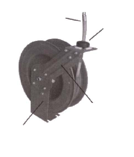
OUTLET HOSE
HOSE STOP
GUIDE ARM
MOUNTING BASE
1
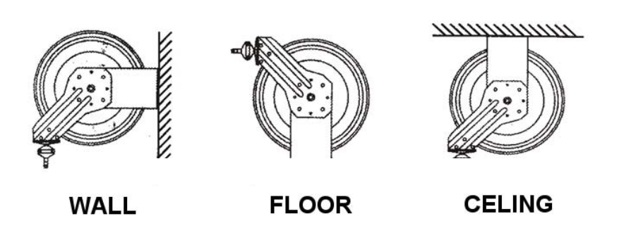
Once you have located a mounting spot, consult the “Typical Mounting Positions” chart below and
choose the diagram that most closely matches your mounting position. If necessary, adjust guide arm
position to match diagram.
Typical Mounting Positions
ADJUSTING THE GUIDE ARM
x Pull out 3 feet of hose and allow reel to lock in position.
x Remove the four bolts connecting guide arm to mounting base.
x Rotate guide arm in 90° increments to desired position total number of positions is five (5).
x Replace four bolts and tighten.
Continue by choosing proper mounting hardware. See illustration on following page for Dimensions.
Use washers on mounting bolts to help bear weight of reel (Bolts and Washers are not included).
After reel is secured in position, attach air hose coming from compressor. Wrap threads of male connector
on incoming air hose with Teflon tape (included) or thread sealant and connect to air inlet valve on side of
hose reel. Connect other end of incoming air hose to air compressor. Apply Teflon tape to threads on hose
before attaching air tools.
WALL FLOOR CEILING
2
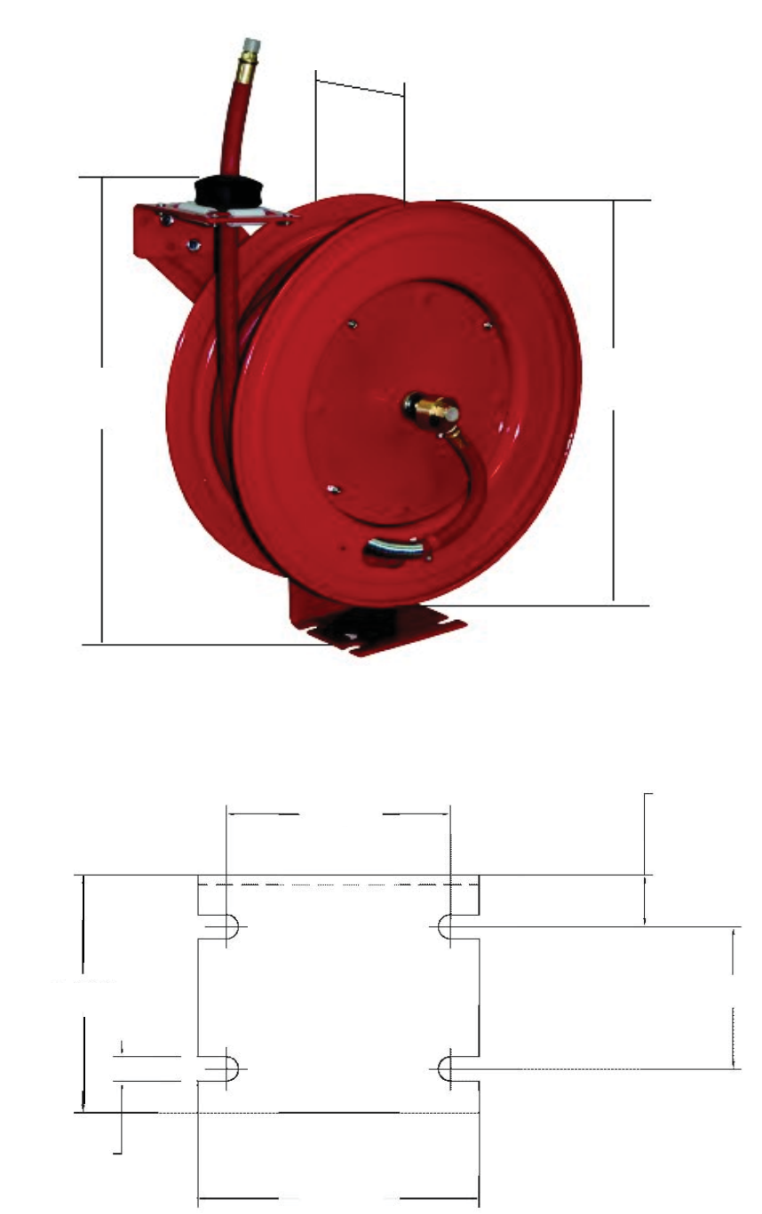
8.464”
(21.5 cm)
22.04”
(56 cm)
20.07”
(51 cm)
4-23/32”
4-15/16”
1/2”
5-29/32”
3”
1-3/16”
3
ADJUSTING THE HOSE BALL STOP
The hose ball stop determines the length of hose that remains outside of reel. To adjust, pull hose out
past desired position of hose ball stop and latch reel. Loosen both screws and move ball stop to proper
position. Tighten screws.
Operating Hose Reel
1. Slowly pull hose from reel to desired length. A ratcheting mechanism inside reel makes a short series
of clicking sounds every half revolution of reel.
2. To lock reel in position, listen for clicking sounds as hose is slowly pulled from reel. When reel clicks,
stop pulling hose. Decrease tension on hose and reel should lock in position.
3. To retract hose onto reel, slowly pull out hose until series of clicking sounds stops (1/8 revolution).
DO NOT LET GO OF HOSE!
4. Allow hose to retract slowly until hose ball stop rests against the hose guide.
5. Periodically check the hose for excessive wear and hose connections for air leaks.
ADJUSTING RECOIL TENSION
1. Disconnect incoming air supply.
2. Pull out about 2 feet of hose and latch the reel.
3. Remove hose ball stop
4. While firmly holding onto edge of reel drum, unlatch reel and carefully allow drum to slowly rewind,
drawing hose end back through guide arm roller assembly and onto reel. Latch reel in position.
5. To Increase Tension: Unlatch reel and turn clockwise (as viewed from air inlet side).
To Decrease Tension: Unlatch and allow reel to rotate slowly counterclockwise (as viewed from air
inlet side).
6. Once desired spring tension is reached, latch reel in position. Feed hose end through roller assembly
in guide arm and reattach hose ball stop.
7. Connect incoming air supply.
REPLACING HOSE
1. Secure and stabilize reel. In most cases, hose can be replaced with reel still mounted.
2. Disconnect incoming air supply.
3. Pull out entire length of hose and lock reel. Make sure reel is securely locked in place.
4. Unscrew hose clamps that secure hose to drum. Disconnect inlet-end of hose from air inlet valve.
5. Pull inlet-end of hose through slot in drum and guide rollers, removing old hose completely.
6. Remove spring hose guard, hose clamp and hose ball stop from old hose. Fit these parts on new
hose in identical positions.
7. Feed inlet-end of hose through guide rollers and slot in drum.
8. Apply Teflon sealant tape or thread sealant to hose connector and connect to air inlet valve.
9. Attach hose clamp to drum. Rewind hose onto reel using normal operation.
4
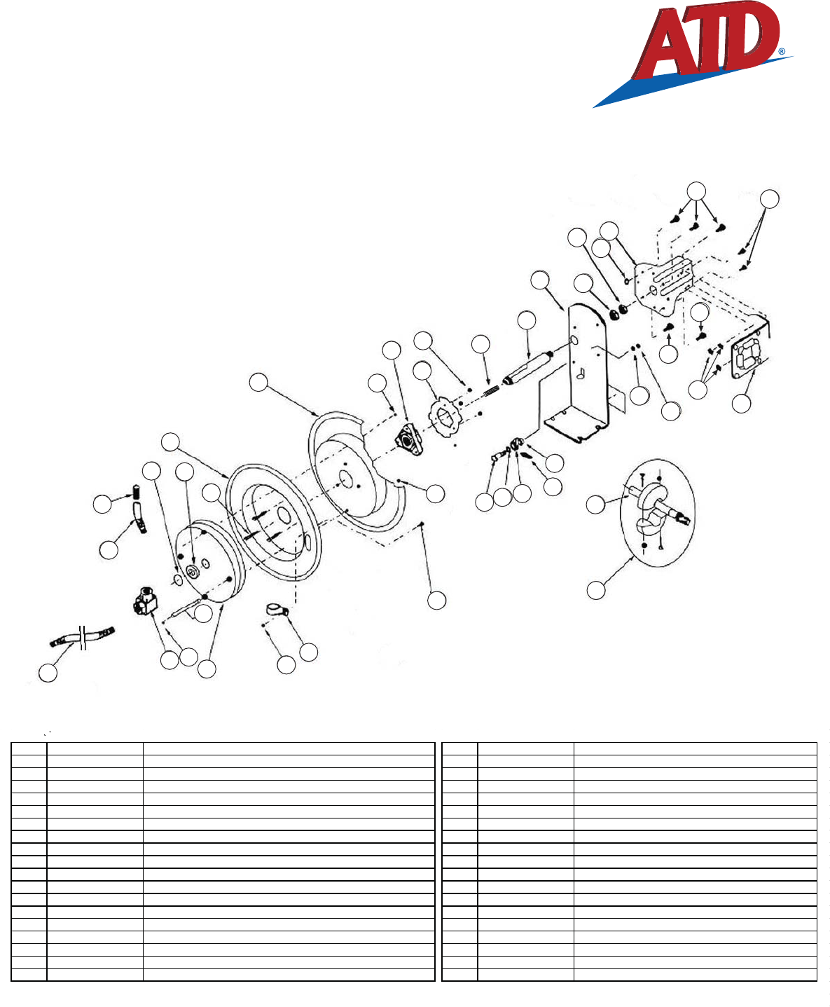
ATD-31166
ITEM# ORDERING PART# PART DESCRIPTION ITEM# ORDERING PART# PART DESCRIPTION
1 PRT31166-01 SPRING CANISTER 20 PRT31166-20 BOLT
2 PRT31166-02 DRUM (AIR INLETSIDE) 21 PRT31166-21 WASHER
3 PRT31166-03 DRUM (MOUNTING BRACKET SIDE) 22 PRT31166-22 NUT
4 PRT31166-04 MOUNTING BRACKET 24 PRT31166-24 BOLT
5 PRT31166-05 GUIDE ARM 25 PRT31166-25 NUT
6 PRT31166-06 AIR INLET VALVE BODY & SWIVEL COLLAR WITH O-RINGS 26 PRT31166-26 LOCK NUT
7 PRT31166-07 3/8ͳHOSE 27 PRT31166-27 ROLLER GUIDE BRACKET ASSEMBLY
8 PRT31166-08 SPRING HOSE GUARD 28 PRT31166-28 HOSE STOPPER ASSEMBLY
9 PRT31166-09 HUB BEARING ASSEMBLY 29 PRT31166-11-29 LOCKING CAM, SPRING, LOCKING GEAR KIT*
10 PRT31166-11-29 LOCKING CAM, SPRING, LOCKING GEAR KIT* 30 PRT31166-30 SPACING WASHER
11 PRT31166-11-29 LOCKING CAM, SPRING, LOCKING GEAR KIT* 31 PRT31166-31 RETAINING RING
12 PRT31166-11-29 LOCKING CAM, SPRING, LOCKING GEAR KIT* 32 PRT31166-32 BOLT
13 PRT31166-13 AXLE 34 PRT31166-34 SET SCREW
14 PRT31166-14 LOCK WASHER 35 PRT31166-35 SPACING WASHER
15 PRT31166-15 NUT 36 PRT31166-36 NUT
16 PRT31166-16 BOLT 37 PRT31166-37 SPACING WASHER
17 PRT31166-17 LOCK NUT 38 PRT31166-38 PIN
18 PRT31166-18 CLAMP 39 PRT31166-39 3/8" LEAD HOSE
*PRT31166-11-29 includes item numbers 10. 11, 12 & 29
25
5
14
15
21
22
24
26
27
32
36
4
32
24
9
10 11 12
13
17
20 28
29
34
35
37 7
17
17
1
2
3
6
7
816
18
25
30
31
38
39
17
5

WARRANTY
1 YEAR LIMITED WARRANTY
THIS WARRANTY AND CONFIRMED RECEIPT(S) SHOULD BE RETAINED BY THE CUSTOMER AT ALL TIMES
PURCHASED FROM: _______________________________________
DATE PURCHASED: ________________________________________
INVOICE/RECEIPT NUMBER: _________________________________________
Your ATD-31166 is warranted for a period of 12 months from the original purchase date.
For a period of one (1) year from your purchase date, ATD Tools Inc. will repair or replace (at its option) without charge, your
ATD product if it was purchased new and the product has failed due to a defect in material or workmanship which you experienced
during normal use of the product. This limited warranty is your exclusive remedy.
To access the benefits of this warranty, contact your supplier, or point of sale directly. You may be advised to return the product
under warranty, freight prepaid, to your supplier for warranty determination.
If this ATD product is altered, abused, misused, modified, or undergoes service by an unauthorized technician, your warranty will
be void. We are not responsible for damage to ornamental designs you place on this ATD product and such ornamentation should
not cover any warnings or instructions or they may void the warranty. This warranty does not cover scratches, superficial dents, and
other abrasions to the paint finish that occur under normal use. It also does not cover normal wear items such as but not limited to
brushes, batteries, drill bits, drill chucks, pads or blades.
Subject to the law in your state:
(1) Your sole and exclusive remedy is repair or replacement of the defective product as described above.
(2) ATD is not liable for any incidental damages, including but not limited to, lost profits and unforeseeable consequences.
(3) The repair and replacement of this product under the express limited warranty described above is your exclusive remedy and is
provided in lieu of all other warranties, express or implied. All other warranties, including implied warranties and warranties of
merchantability or fitness for a particular purpose are disclaimed and, if disclaimer is prohibited, these warranties are limited to
one year from your date of purchase of this product.
Some states’ laws do not allow limited durations on certain implied warranties and some states’ laws do not allow limitations on
incidental or consequential damages. You should consult the law in your state to determine how your rights may vary.
[Affix receipt or invoice here for safe keeping]
6
