ATD7888_rev_0618 ATD7888 Rev 0618
User Manual: Pdf ATD7888_rev_0618
Open the PDF directly: View PDF ![]() .
.
Page Count: 7
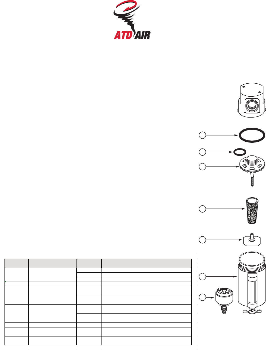
Filter Instruction Sheet
ATD-7782
(ATD-7888)
IS-F35-1V-S50
06/18
Bowl
Plastic
Metal
W/sight
Max. Pressure
150 psi
250 psi
250 psi
Temperature Range
40°F to 125°F
40°F to 200°F
40°F to 160°F
1
2
3
4
5
6
7
EK35 40 MICRON SINTERED BRONZE ELEMENT
EK35-5 5 MICRON SINTERED BRONZE ELEMENT
EK35-3 3 MICRON ABSOLUTE ELEMENT
2, 3, 5 REPAIR KIT RKF35 RETAINER/VANE ASSEMBLY, O-RING, BAFFLE
BKF45W
(6 OZ.)
METAL BOWL, SIGHT, DRAIN COCK, BALL, O-RING
BKF46W
(9 OZ.)
METAL BOWL, SIGHT, DRAIN COCK, BALL, O-RING
BKF35 POLYCARBONATE PLASTIC BOWL WITH PUSH
DRAIN, O-RING, BOWL GUARD
BKF45M
(
6 OZ.
)
METAL BOWL WITHOUT SIGHT, DRAIN COCK, O-
RING
NOT SHOWN SIGHT KIT WK45 SIGHT TUBE, RETAINER, INDICATOR BALL, O-RING
7 AUTO DRAIN (OPTIONAL) 5200 FLOAT DRAIN ASSEMBLY, BOWL INSERT, O-RING,
RETAINER RING
8 OVERNIGHT DRAIN CKFK OVERNIGHT DRAIN ASSEMBLY, BOWL INSERT, O-
RING, RETIAINER RING
BOWL KIT1, 6
BOWL KIT (OPTIONAL)NOT SHOWN
ITEM DESCRIPTION CONTENTSKIT NUMBER
ELEMENT KIT4
Model 5200 Internal Float Drain Available (Item #7) To be used for pressures from 30 psi to 175 psi
and from 40°F to 120°F. To order filter with float drain assembled, add suffix “F” to filter model number.
ATD-7888
STAGE 1 - ATD-7782
WARNING! For compressed air service only. Do not use on life support systems or breathing air
systems. Never use polycarbonate plastic bowls with air supplied by a compressor lubricated
with synthetic oils or oils containing phosphate esters or chlorinated hydrocarbons. They can
carry over into the air distribution system and chemically attack and possibly rupture the bowl.
On these applications use a metal bowl. Also, do not expose the polycarbonate plastic bowl to
materials such as trichloroethylene, acetone or paint thinner. Cleaning fluids or other harmful
materials will craze and/or rupture the bowl. If materials harmful to polycarbonate are present
either inside or outside the bowl, use a metal bowl. For any additional information regarding
chemical compatibility, please contact: General Electric Plastics, One Plastic Ave, Pittsfield, MA.
INSTALLATION: Install dryer so that air flows in the direction indicated by the arrow on the head
of install filter upstream of regulators and lubricators, and as close as possible to the pneumatic
tools or appliance being serviced. Do not instill polycarbonate bowl in pressures that exceed
150psi or where there is a presence of solvents harmful to polycarbonate. In these cases, use a
metal bowl.
MAINTENANCE AND OPERATION: Filtering out of dirt and foreign particles, and the separa-
tion of moisture is automatic with air flow. There are no moving parts and no adjustments are
necessary. Accumulated sludge and moisture should be drained off. Sediment should not be
permitted to fill above the lower baffle.
Wash filter element at intervals with naphtha to maintain filtering efficiency. To clean element,
depressurize system, unscrew polycarbonate bowl, and unscrew element from head. Dry filter
element thoroughly before reassembling. Clean filter bowl(s) only with soapy water. Inspect
o-ring, replacing if damaged or distorted. Reassemble with care to avoid stripping threads on
bowl. After a metal bowl with sight is tightened, it may be rotated up to 180° for proper viewing.
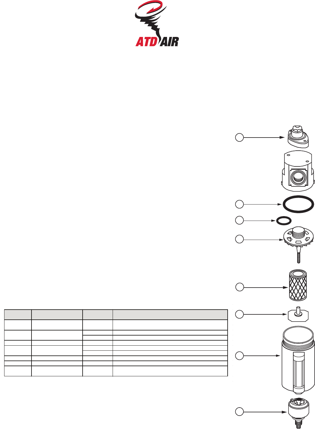
Coalescing Instruction Sheet
ATD-7785
(ATD-7888)
IS-F45/55-1VS50
06/18
Bowl
Metal
W/Sight
W/Auto Drain
Max. Pressure
250 psi
250 psi
30 psi to 175 psi
Temperature Range
40°F to 200°F
40°F to 160°F
40°F to 120°F
1
2
3
4
5
6
7
8
ATD-7888
STAGE 2 - ATD-7785
BKF45M METAL BOWL, DRAIN COCK, O-RING
BKF45W METAL BOWL, SIGHT, DRAIN COCK, O-RING
3, 4, 6 REPAIR KIT RKF45 RETAINER, O-RING, BAFFLE
EK55 .03 MICRON COALESCING ELEMENT
(
STD
)
EK55A .01 MICRON COALESCING ELEMENT
NOT SHOWN SIGHT KIT WK45 SIGHT TUBE, RETAINER, INDICATOR BALL, O-RING
NOT SHOWN MOUNTING BRACKET FBK5 MOUNTING BRACKET, SCREWS
8 AUTO DRAIN (OPTIONAL) 5200 FLOAT DRAIN ASSEMBLY, BOWL INSERT, O-RING,
RETAINER RING
ELEMENT KIT
ITEM DESCRIPTION KIT NUMBER CONTENTS
1 INDICATOR SIGHT KIT DPK05 SCREWS, SIGHT GLASS, SPRING BRACKET, O-RING,
INNER & OUTER CYLINDERS, SIGHT DOME
2,7 BOWL KIT
5
WARNING! For compressed air service only. Do not use on life support systems or breathing
air systems. Metal bowl sight is made of polycarbonate which will craze and/or crack if
exposed to chemicals incompatible with polycarbonate. For any additional information regard-
ing chemical compatibility, please contact: General Electric Plastics, One Plastic Ave,
Pittsfield, MA.
INSTALLATION: Install dryer so that air flows in the direction indicated by the arrow on the
head of unit. Install filter upstream of regulators. If an air dryer is being used, install the filter
downstream from the dryer. In most cases, a particulate pre-filter with a 3 micron absolute
element is recommended to greatly extend the life of the coalescer element. When the
coalescer element becomes clogged with dirt, it must be replaced. If it is kept free from dirt, it
will coalesce oil indefinitely. A pre-filter will remove water and dirt before it reaches the
coalescer, and will reduce maintenance costs. The coalescer filter is then free to remove oil, oil
vapors, and submicron sized particles without prematurely clogging with large particles of dirt
and scale.
WARNING! Units are die cast aluminum, do not torque while installing. Also, pressurize unit
slowly after installation of unit or new element to avoid damage to the element.
OPERATION ADJUSTMENTS: If the filter is installed properly, it should give long, trouble-free
service. The pressure drop across the filter should not exceed 10 psi. If the pressure drop
exceeds 10 psi, either the filter element needs to be replaced or the unit is being operated
beyond its capacity and a larger size unit is required. Operating the filter at a pressure drop in
excess of 10 psi will greatly reduce the efficiency of the filter.
DIFFERENTIAL PRESSURE INDICATOR MAINTENANCE (#1 ON THE DRAWING): When
The filter is depressurized, periodically clean and grease the piston o-ring with a non-silicon
ring grease (see item 1 in drawing).

KIT NUMBER
ATD-7889
1, 2, 3, 4 BOWL KIT BKD1206 BOWL O-RING, BOWL ASSY W/SIGHT, BOWL
ADAPTER, BOWL RING
5, 6, 7, 8,
9, 13, 14
REPAIR KIT RKD1206
EXT. RETAINING E-RING, LEAD IN O-RING,
LEAD IN BULLET, EXHAUST TUBE, THREADED
ROD, DRAIN PLUG ADAPTER O-RING
10, 11, 12 ELEMENT KIT EKD1206 DISPERSION FILTER, EXHAUST ELEMENT
GASKET
NOT
SHOWN
SIGHT KIT SKD10 SIGHT BODY, O-RINGS, RETAINING NUT, SIGHT
DOME, DOME RETAINER
ITEM DESCRIPTION CONTENTS
Desiccant Dryer Instruction Sheet
ATD-7889
(ATD-7888)
IS-D12-S50
06/18
Bowl
Metal w/sight
Max. Pressure
250 psi
Temperature Range
40°F to 160°F
NOTE: To prevent excessive pressure drop, it is recommended that the exhaust element be
replaced whenever the desiccant is replaced or discharged.
(O-RING)
1
2
3
4
5
6
7
8
9
10
11
12
13
14
ATD-7888
STAGE 3 - ATD-7889
WARNING! For compressed air service only. Do not use on life support systems or breathing
air systems. Metal bowl sight is made of polycarbonate resin that will crack if exposed to
solvents or oils containing ethyl acetate, methylene dichlorobenzene or any partially haloge-
nated or aromatic hydrocarbons. For any additional information regarding chemical compat-
ibility, please contact: General Electric Plastics, One Plastic Ave, Pittsfield, MA.
INSTALLATION: Install dryer so that air flows in the direction indicated by the arrow on the
head of the unit. A prefilter combination is always required upstream of the dryer. First stage
filtration with a particulate filter will remove water and solid particles down to 40 microns in
size. Second stage filtrations with a coalescing filter will remove oil and water particulates
down to 0.03 microns.
NOTE: Used desiccant material can be regenerated by spreading the desiccant in a thin layer
in a shallow pan and then heating it in a convection oven at 275°F until a complete color
change occurs, usually within about 3 hours. Caution - avoid excessive temperatures and do
not regenerate your desiccant in an oven that is used for food consumption use.
MAINTENANCE AND OPERATION: Care must be taken to change or regenerate the dryer
desiccant material once it appears pink in color. The following steps are to be taken when
recharging the dryer: 1) Shut off air supply and bleed system. 2) Unscrew bowl ring and
remove bowl assembly. 3) Remove used desiccant. 4) Unscrew lead-in bullet from threaded
rod. 5) Remove exhaust tube, exhaust element and gasket. 6) Inspect and clean inside of
exhaust tube if necessary and then reassemble the main assembly. 7) Remove sight retainer
and sight o-ring. 8) Discard used desiccant within the sight body. 9) Fill sight body with new
or regenerated desiccant. 10) Secure sight and o-ring by hand-tightening sight dome retainer.
11) Fill bowl with new or regenerated desiccant to 1/2” from top bowl flange. Replace bowl
assembly and hand-tighten bowl ring. CAUTION: DO NOT REMOVE SIGHT RETAINER
WHILE BOWL IS UNDER PRESSURE.
STORAGE: Store replacement desiccant in a dry area making certain that the jar is tightly
sealed with a shelf life noted.

Filter / Regulator Instruction Sheet
ATD-7790
(ATD-7888)
IS-B75-1-S50
06/18
Bowl
Metal
W/Sight
W/Auto Drain
Max. Pressure
250 psi
250 psi
30 psi to 175 psi
Temperature Range
40°F to 200°F
40°F to 160°F
40°F to 120°F
ATD-7888
STAGE 4 & 5 - ATD-7790
WARNING! For compressed air service only. Do not use on life support systems or breathing air systems. Never use polycarbon-
ate plastic bowls with air supplied by a compressor lubricated with synthetic oils or oils containing phosphate esters or chlorinated
hydrocarbons. They can carry over into the air distribution system and chemically attack and possibly rupture the bowl. On these
applications use a metal bowl. Also, do not expose the polycarbonate plastic bowl to materials such as trichloroethylene, acetone
or paint thinner. Cleaning fluids or other harmful materials will craze and/or rupture the bowl. If materials harmful to polycarbonate
are present either inside or outside the bowl, use a metal bowl. For any additional information regarding chemical compatibility,
please contact: General Electric Plastics, One Plastic Ave, Pittsfield, MA.
MAINTENANCE AND OPERATION:
FILTER: Filtering out of dirt and foreign particles, and the separation of moisture is automatic with air flow. There are no moving
parts and no adjustments are necessary. Accumulated sludge and moisture should be drained off. Sediment should not be
permitted to fill above the lower baffle.
Wash filter element at intervals with naphtha to maintain filtering efficiency. To clean element, depressurize system, unscrew
polycarbonate bowl, and unscrew element from head. Dry filter element thoroughly before reassembling. Clean filter bowl(s) only
with soapy water. Inspect o-ring, replacing if damaged or distorted. Reassemble with care to avoid stripping threads on bowl. After
a metal bowl with sight is tightened, it may be rotated up to 180° for proper viewing.
REGULATOR: The regulator will accurately control secondary pressure between 2 and 125 PSI. The self-bleed venting feature
permits use on dead end applications.
After the regulator is installed, back off pressure adjusting knob before the air is turned on. Turn on the air supply and regulate
the adjusting knob until pressure gauge shows the desired pressure. To lock adjusting knob, push down until knob snaps into
locking groove. To make regulator tamper-resistant, remove adjusting knob from unit. Regulator may be adjusted by replacing
knob.
IMPORTANT! Use care to avoid screwing fittings too far into body of units as it may close internal ports. Normally finger tight plus
one turn will seal.
TAMPER RESISITANT OPTION: The tamper-resistant cap (P/N 75104) has been provided in the plastic bag to ensure that the
reduced pressure cannot be tampered with. To make the unit “tamper-resistant”, proceed as follows:
Turn the adjustment knob until desired pressure is reached. Remove the adjustment knob by pulling upward. Install the tamper
resistant cap in its place.
NOTE: To make permanently tamper-resistant, LOCTITE the cap into place.
CAUTION: By permanently applying LOCTITE to keep the tamper-resistant cap into place, the pressure adjustment cannot be
changed.
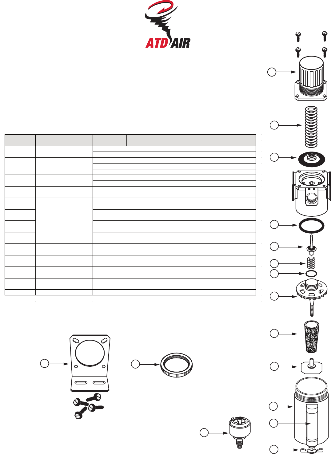
2
3
4
5
6
7
1
8
9
10
11
12
13
14
15 16
P
U
L
L
T
O
A
D
J
U
S
T
P
U
S
H
T
O
L
O
C
K
Filter / Regulator Instruction Sheet (Continued)
ATD-7790
(ATD-7888)
SC35 CAP, BONNET LOCK SCREWS
SC35T T-HANDLE
SK35 ADJUSTING SPRING, 2-125 PSI
SK35L ADJUSTING SPRING, 2-60 PSI
SK35H ADJUSTING SPRING, 2-250 PSI
DK35 VALVE ASSEMBLY, O-RING, SPRING
DK35N GASKET, BACK CAP
ELEMENT KIT EK35-3 3 MICRON ABSOLUTE ELEMENT
EK35-5 5 MICRON SINTERED BRONZE ELEMENT
NOT SHOWN BKF35 POLYCARBONATE PLASTIC BOWL WITH PUSH DRAIN, O-
RING, BOWL GUARD
4, 11, 13 BKF45M
(
6 oz.
)
METAL BOWL WITHOUT SIGHT, DRAIN COCK, O-RING
4, 11, 12, 13 BKF45W
(
6 oz.
)
METAL BOWL, SIGHT, DRAIN COCK, BALL, O-RING
4, 11, 12, 13 BKF46W
(
9 oz.
)
METAL BOWL, SIGHT, DRAIN COCK, BALL, O-RING
5, 6, 7, 8, 10 VALVE KIT VKB75 VALVE PLUNGER, SPRING, O-RING, VANE ASSEMBLY,
BAFFLE
12 SIGHT GLASS WK45 SIGHT TUBE, O-RINGS
NOT SHOWN OVERNIGHT DRAIN
(
OPTIONAL
)
CKFK OVERNIGHT DRAIN ASSEMBLY, BOWL INSERT, O-RING,
RETAINER RING
14 AUTO DRAIN KIT
(
OPTION
A
5200 FLOAT DRAIN ASSEMBLY
15 MOUNTING BRACKET RBK5 MOUNTING BRACKET, SCREWS
16 PANEL MOUNT RING PKR35 PANEL MOUNT RING
ITEM DESCRIPTION KIT NUMBER CONTENTS
1 REGULATOR BONNET
REPAIR KIT
2 ADJUSTING SPRING KIT
3 DIAPHRAGM REPAIR KIT
9
BOWL KIT

MODULAR CONNECTOR INSTRUCTION SHEET
IS-IK50-S50
06/18
Assemble and Disassemble Units Quickly and Easily
Install the end port O-ring in the
end port. O-ring groove provided
on each product end port.
Slide the insert onto the product
end port. The insert will now be
held in place by the end port
safety bars.
Align the insert lock plate assembly
with the insert plate holes.
Tighten to snug ¿W which will me-
chanically lock the insert in place
and form a wedge O-ring seal with
the end port.
When assembling combinations
together use a connector insert
kit or diverter insert kit
Slide the insert against the O-ring
seal on product.
Then repeat this process with the
end port seal on the next product
keeping in mind the direction of
ÀRw.
Lock up the insert plate and simply
repeat this process for linking up
additional product.
Simply unscrew lock plates and slide
unit out. Reverse the procedure to
install.
Change Units
On-Line Without
Disturbing Piping
This exploded view drawing
illustrates the engineering
uniqueness of the modular
system. Components shown
can be ordered as a total sys-
tem, or as individual items.
Item Kit Description Kit Number Contents
2, 3, 4 Modular Connector Insert Kit IK50 Modular insert, cover plate assembly, (2) O-Rings
1, 3, 4 1/4 NPT Pipe Port Kit IK52 (2) 1/4 NPT Modular Pipe Ports, (2) Cover Plate
Assemblies, (2) O-Rings
3/8 NPT Pipe Port Kit IK53 (2) 3/8 NPT Modular Pipe Ports, (2) Cover Plate
Assemblies, (2) O-Rings
1/2 NPT Pipe Port Kit IK54 (2) 1/2 NPT Modular Pipe Ports, (2) Cover Plate
Assemblies, (2) O-Rings
3/4 NPT Pipe Port Kit IK56 (2) 3/4 NPT Modular Pipe Ports, (2) Cover Plate
Assemblies, (2) O-Rings
Not 1/4 NPT Diverter Modular Kit DK52 (1) 1/4 NPT Diverter Module, (2) Cover Plate
Shown Assemblies, (2) O-Rings
3/8 NPT Diverter Modular Kit DK53 (1) 3/8 NPT Diverter Module, (2) Cover Plate
Assemblies, (2) O-Rings
1/4 NPT - 3 Port Diverter DK54 (1) 1/4 NPT - 3 Port Diverter Module, (1) Cover
Modular Kit Plate Assembly, (1) O-Ring
Connector
Insert
Pipe Port
Insert
Pipe Port
Insert
Lock Plate
Assembly
O-Rings
Filter Regulator Lubricator
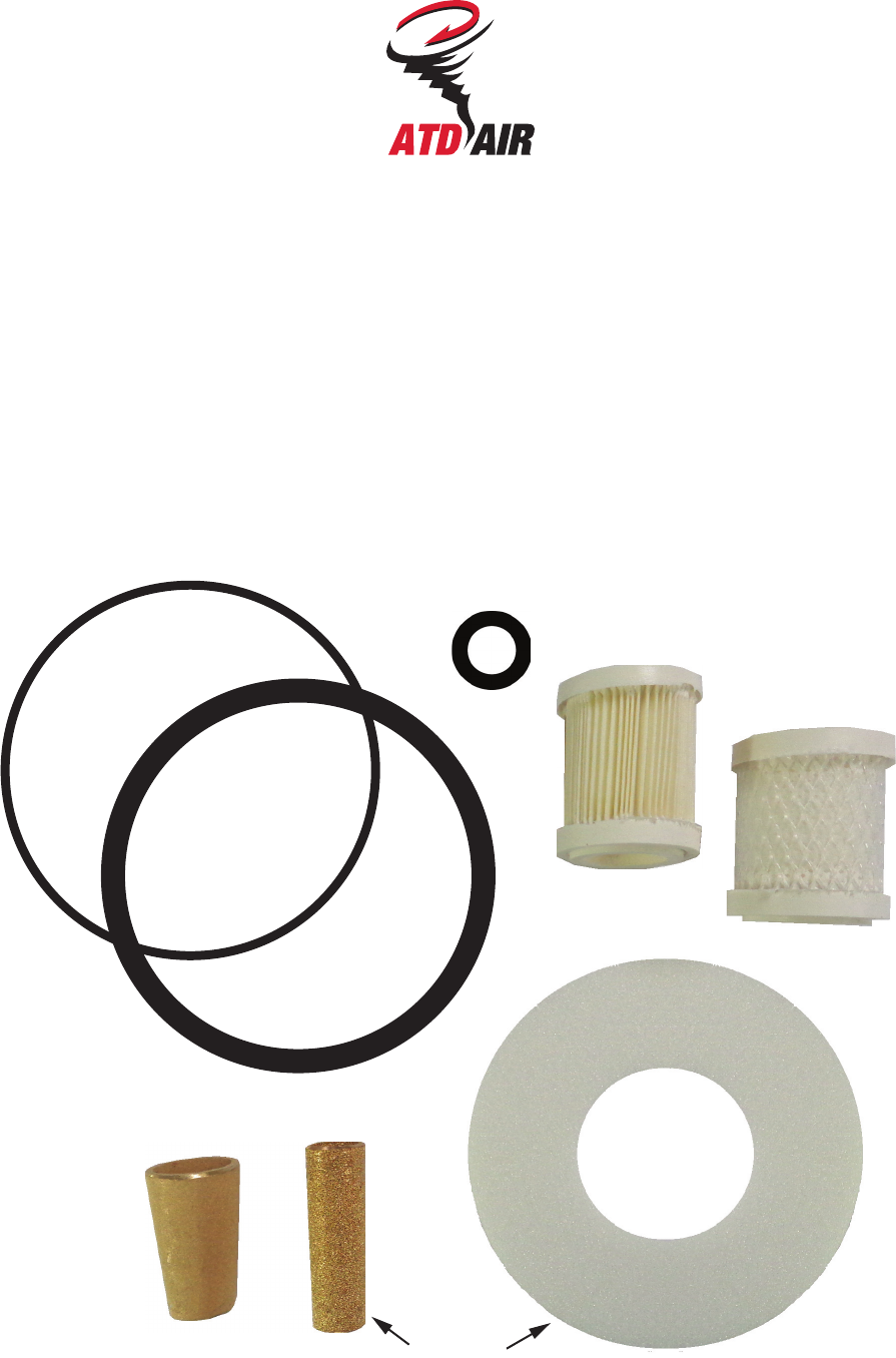
ATD-78881
Filter Element Change Kit for ATD-7888
Complete Filter Change Kit Includes:
Stage 1 - 5 micron particulate filter element (EK35-5)
Stage 2 - .01 micron oil removing filter element (EK55A)
Stage 3 - Desiccant Dryer dispersion element & intake tube element (EKD1206), O-Ring (3460-70)
Stage 4/5 - 3 micron absolute filter element (EK35-3)
Stage 1, 2 or 4 - Spare O-Ring (1560-70)
Stage 4/5 - Element Gasket (33089)
EK35-5
EK55A
EK35-3
3460-70
1560-70
EKD1206
33089
