AFFIXUS Hip Fracture Nail Surgical Technique
2016-04-01
: Pdf Affixus Hip Fracture Nail Surgical Technique AFFIXUS_Hip_Fracture_Nail_Surgical_Technique 3 2016 pdf
Open the PDF directly: View PDF ![]() .
.
Page Count: 36
Surgical Technique
Over 1 million times per year, Biomet helps one surgeon
provide personalized care to one patient.
The science and art of medical care is to provide the right
solution for each individual patient. This requires clinical
mastery, a human connection between the surgeon and the
patient, and the right tools for each situation.
At Biomet, we strive to view our work through the eyes of one
surgeon and one patient. We treat every solution we provide
as if it’s meant for a family member.
Our approach to innovation creates real solutions that assist
each surgeon in the delivery of durable personalized care
to each patient, whether that solution requires a minimally
invasive surgical technique, advanced biomaterials or a
patient-matched implant.
When one surgeon connects with one patient to provide
personalized care, the promise of medicine is fullled.
One Surgeon. One Patient.

1
Contents
Features and Benets .........................................................................................................................................................................................................3
Indications and Pre-op Planning ....................................................................................................................................................................................7
Patient Positioning and Reduction ................................................................................................................................................................................8
Entry and Canal Preparation ............................................................................................................................................................................................9
Nail Insertion ....................................................................................................................................................................................................................... 12
Proximal Locking ............................................................................................................................................................................................................... 15
Distal Locking ..................................................................................................................................................................................................................... 23
End Cap Placement .......................................................................................................................................................................................................... 25
Implant Removal ............................................................................................................................................................................................................... 26
Implant Diagrams.............................................................................................................................................................................................................. 27
Product Ordering Information ..................................................................................................................................................................................... 28
George J. Haidukewych, MD
Orlando, FL
Daniel S. Horwitz, MD
Salt Lake City, UT
Frank A. Liporace, MD
Newark, NJ
S. Andrew Sems, MD
Rochester, MN
US Surgeon Design Team
Peter Giannoudis, MD
Leeds, UK
International Surgeon
Designer
AFFIXUS Hip Fracture Nail
2
3
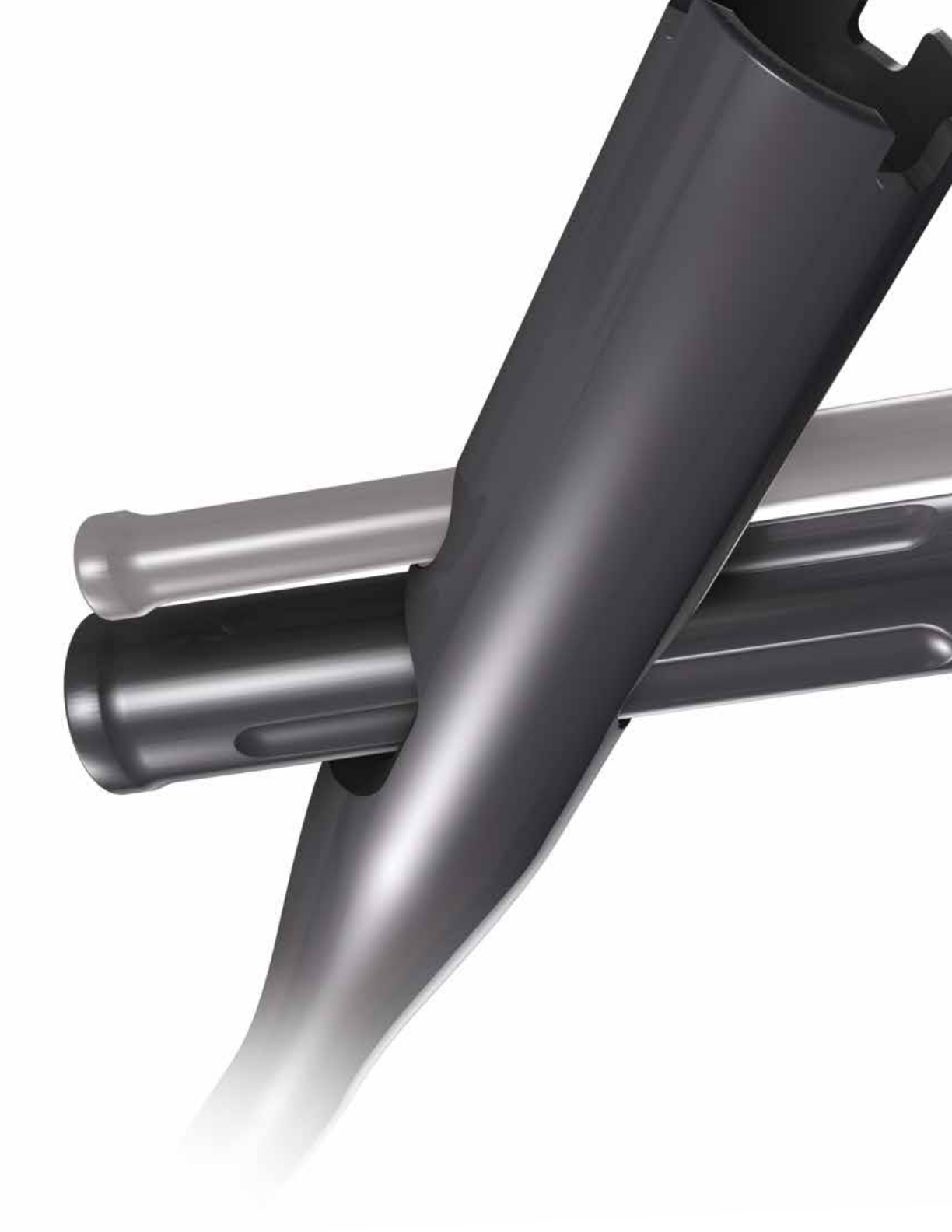
Strength and Stability in the Proximal Femur
• Optimal lag screw design for resistance to cut-out
• Easy-to-use instrumentation and targeting jig,
which includes Goal Post technology,
aids in lag screw placement
• Extensive range of neck/shaft angles, distal diameters,
and nail lengths – combined with a small proximal nail
diameter – allows the surgeon to achieve a close match
for each patient’s anatomy
• Unique distal bend facilitates entry through
the proximal 1/3 of the femur and reduces potential
for anterior cortex penetration
AFFIXUS Hip Fracture Nail
4
AFFIXUS Hip Fracture Nail
A system of choices for effective treatment
of proximal femoral fractures
• Short (180 mm) and long (260 - 460 mm) nail options
treat a wide range of proximal fracture indications using
a single set of user-friendly instruments
• 15.6 mm proximal nail diameter
• Proximal 4˚ lateral bend allows for greater
trochanteric entry site
• 125˚ and 130˚ neck angles provide a range
of anatomical options
• 10˚ of proximal anteversion built into the nails
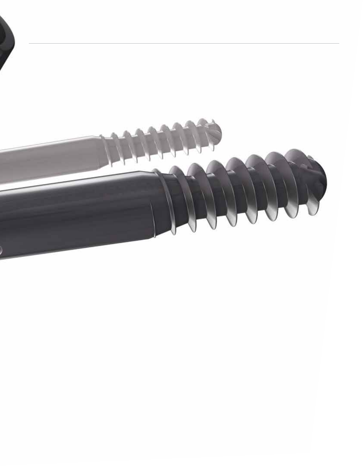
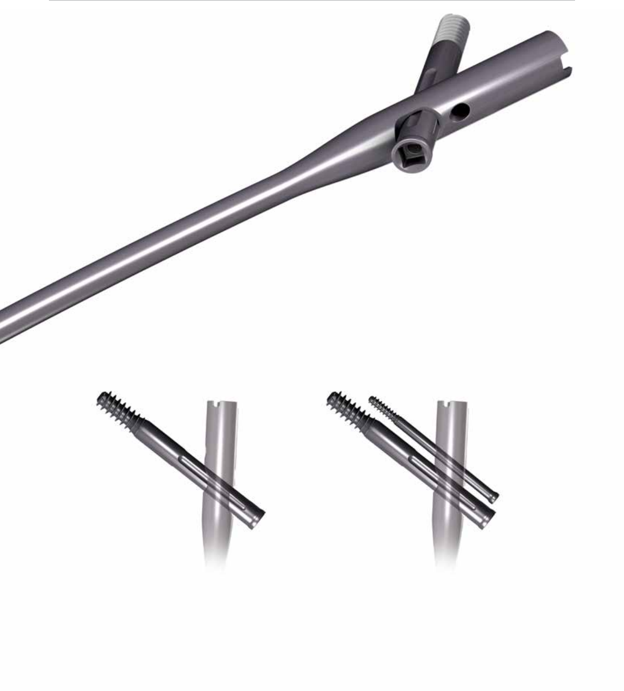
• 10.5 mm diameter cannulated lag screw for bone
preservation
• Unique thread spacing and design of the lag screw
helps to resist displacement and cut-out
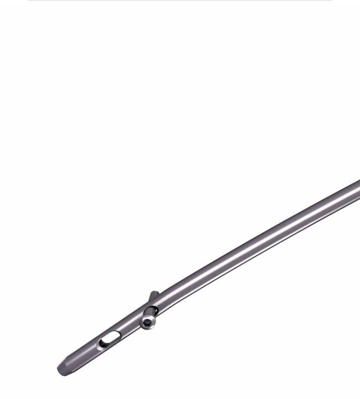
• Chamfer on the front distal tip helps facilitate
insertion and minimizes risk of stress on
the anterior cortex in the distal femur
• 3° distal bend facilitates ease of insertion through
the proximal intertrochanteric/subtrochanteric region
• Pre-loaded set screw for ease of use
• 5.0 mm anti-rotation (AR) screw for rotational
control (optional)
• Shouldered lag screw and AR screw help prevent medial
screw disengagement
• Long nail maintains a 1.8 M radius of curvature
to closely match the femoral anatomy
• 5.0 mm diameter distal interlocking screws have
a large core diameter for strong xation
• Static or dynamic distal locking options
with a 6 mm dynamization range
5
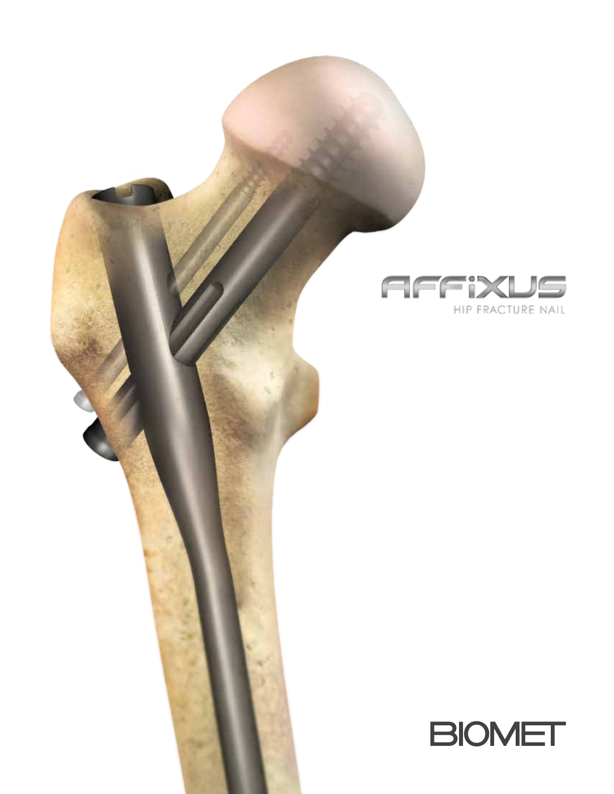
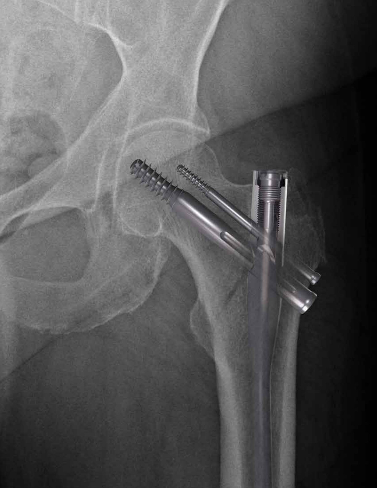
Multiple locking options for optimal implant stability
The AFFIXUS Hip Fracture Nail System, comprised of short and long nails, provides surgeons with
an intramedullary hip screw to stabilize fractures of the proximal femur. The AFFIXUS Hip Fracture
Nail combines the principles of a compression hip screw with the biomechanical advantages of an
intramedullary nail.
6
AFFIXUS Hip Fracture Nail
6
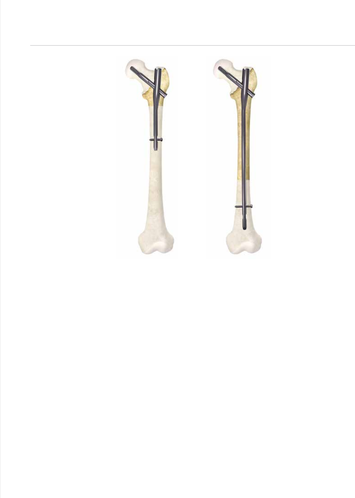
Figure 1
7
Indications and Pre-op Planning
AFFIXUS Hip Fracture Nail
Short – (180 mm)
AFFIXUS Hip Fracture Nail
Long – (260 - 460 mm)
Figure 1
AFFIXUS Hip Fracture Nail
The AFFIXUS Hip Fracture Nail System* is designed for
antegrade trochanteric insertion to treat the following
fractures (Figure 1):
The AFFIXUS Hip Fracture Nail System is intended to
treat stable and unstable proximal fractures of the femur
including pertrochanteric fractures, intertrochanteric
fractures, high subtrochanteric fractures and combinations
of these fractures, including non-union, malunion and
tumor resections. The Long Nail system is additionally
indicated to treat pertrochanteric fractures associated
with shaft fractures, pathologic fractures in osteoporotic
bone (including prophylactic use) of the trochanteric and
diaphyseal areas, impending pathological fractures, long
subtrochanteric fractures, ipsilateral femoral fractures,
proximal or distal non-unions, malunions, revision
procedures and tumor resections.
Note: Bone screws referenced in this material are not
intended for screw attachment or xation to the posterior
elements (pedicles) of the cervical thoracic or lumbar
spine.
* System includes short (180 mm) and long (260-460 mm) nails,
in 20 mm increments.
8
AFFIXUS Hip Fracture Nail
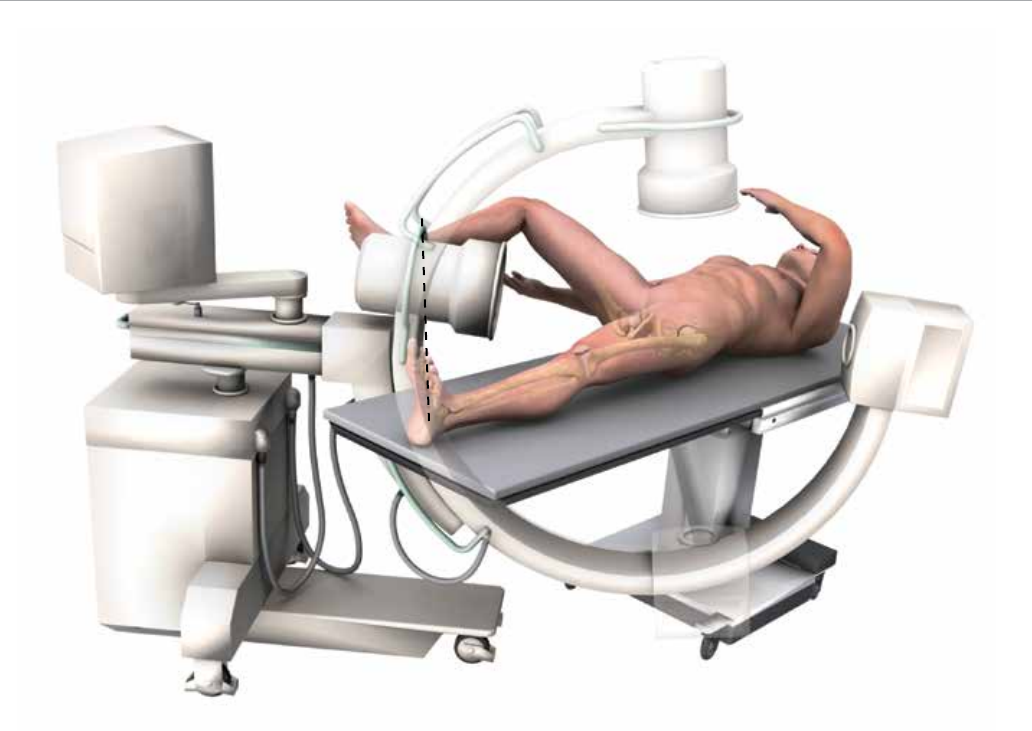
Figure 2
Patient Positioning and Reduction
Place the patient in the supine or lateral position on a
fracture table or radiolucent imaging table. Lateral access
to the proximal femur is required. Intraoperative image
intensication with a C-arm is required to obtain AP and
lateral imaging of the operative area during preoperative
preparation (reduction) and throughout the procedure
for nail insertion, nail locking, and anteversion alignment.
Avoid excessive abduction of the hip during reduction
as the access to the starting point and nail insertion may
be impeded. The trunk may be laterally exed away from
the operative side to improve access to the starting point.
The contralateral leg may be exed at the hip or scissored
below the aected leg in the supine position (Figure 2).
Closed Fracture Reduction
Fluoroscopy must be used to verify proper fracture
reduction.
• Acceptable fracture alignment must be obtained prior to
implant insertion
• Surgeon must avoid varus malreductions
• Use a combination of traction, rotation, adduction, and
exion/extension of the leg to obtain an acceptable
reduction
• Open reductions may be required for more complicated
fracture patterns and should be used when an acceptable
closed reduction cannot be obtained (see page 10)
Initial Incision
Make an incision proximal to the tip of the greater
trochanter in line with the femoral axis. Divide the fascia
lata in line with its bers and access the tip of the greater
trochanter.
9
Awl
Figure 5 Figure 6
Entry reamer shape
matches proximal nail
shape
Figure 4
Entry and Canal Preparation
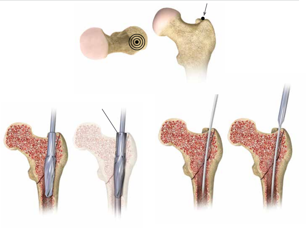
Trochanteric entry point
Figure 3
Femoral Entry Preparation
Attach the standard 3.2 mm guide pin to the pistol
guidewire gripper or power source and pass it through the
tip of the greater trochanter into the center of the femoral
canal. Position the entry on the tip of the greater trochanter
(Figure 3). Conrm on AP and lateral uoroscopy views that
the entry pin is centered on the trochanter.
Option 1:
Cannulated Entry Reamer
(One-step 16.6 mm)
Attach the cannulated entry reamer to the power source
and pass it over the guide pin through the entry portal
(Figure 4).
It is essential to ream until the reamer’s proximal shaft
passes with the greater trochanter’s cortical bone as the
shape of the entry reamer matches the nail shape and the
top of the cylindrical segment of the reamer corresponds
to the top of the nail (Figure 4). Reaming should continue
until the tip of the entry reamer is at the level of the lesser
trochanter and not beyond.
Option 2: Cannulated Awl
Pass the cannulated awl over the guide pin and introduce
with a rotation motion until the awl is buried to at least half
its blade length (Figure 5 & 6).
10
AFFIXUS Hip Fracture Nail
Figure 7
Figure 8
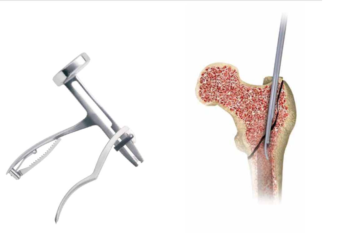
Open Fracture Reduction
Once access to the femoral canal has been gained, place
the ball nose guide wire into the entry site utilizing the
pistol guide wire gripper (Figure 7).
Obtain appropriate anatomic reduction in order to
restore length, anatomic axis alignment, and rotation
of the injured limb. Reduction can be achieved through
the surgeon’s preferred method such as traction,
external xator, external aids, or joysticks. To aid in
manipulating the fracture fragments and passing the
ball nose guide wire, long (7.5 mm diameter) and short
(6.5 mm diameter) reduction tools are available.
Insert the reduction tool into the medullary canal, past the
fracture site. Once the fracture is in alignment, pass the
ball nose guide wire, available in both 80 cm and 100 cm
lengths, across the fracture site. Remove the reduction tool
(Figure 8).
11
Figure 9
Figure 10
Canal Preparation
Short Nail
Conrm that the femoral diaphysis is wide enough and
long enough to allow the selected nail diameter to pass.
Ream as necessary to enlarge the diaphysis to accept the
selected nail.
Long Nail
Achieve proper alignment of the injured limb prior to reaming.
Maintain alignment throughout the reaming process to
avoid eccentric reaming. Commence reaming by placing
the exible reamer over the ball nose guide wire (Figure 9).
Ream the medullary canal in millimeter increments
until cortical bone is reached and in half-millimeter
increments thereafter. Surgeon preference should dictate
the actual extent of intramedullary reaming. Monitor
the reaming procedure using image intensication
to avoid eccentric or excessive cortical reaming.
Note: It is recommended to over-ream the diaphysis by 2 mm.
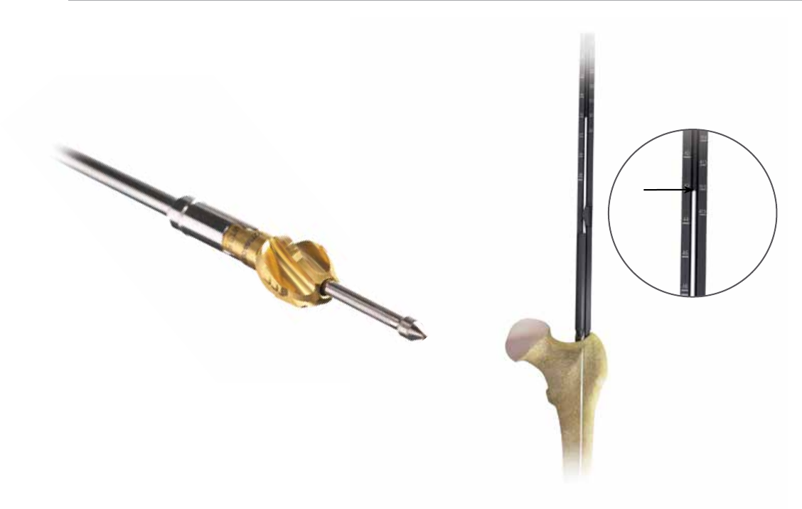
Nail Length Selection
With the tip of the ball nose guide wire at the level of the
desired depth of nail insertion, slide or snap the nail depth
gauge onto the ball nose guide wire until it contacts the
bone, ensuring that the tip does not fall into the existing
trochanteric entry canal, thus providing an inaccurate
measurement. To obtain the appropriate nail length, read
the measurement mark on the nail depth gauge that is
closest to the beginning of the black transition area on
the guide wire (Figure 10). If a nail of the exact measured
length is not available, choose a shorter nail of the next
closest available length. A direct measurement can also be
taken of the uninjured extremity using either radiographs
with magnication markers, or directly on the uninjured
limb.
12
AFFIXUS Hip Fracture Nail
Alignment of proximal
targeting
Figure 11 Figure 12
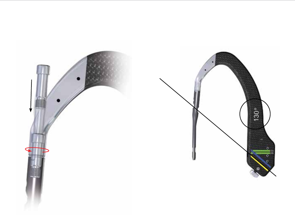
Nail Insertion
Jig Assembly
Select the appropriate targeting jig that corresponds to
the neck shaft angle of the implant selected. Insert the
jig bolt through the targeting jig using the jig bolt driver
(Figure 11).
Note:
130º neck angle is most commonly used (Figure 12).
13
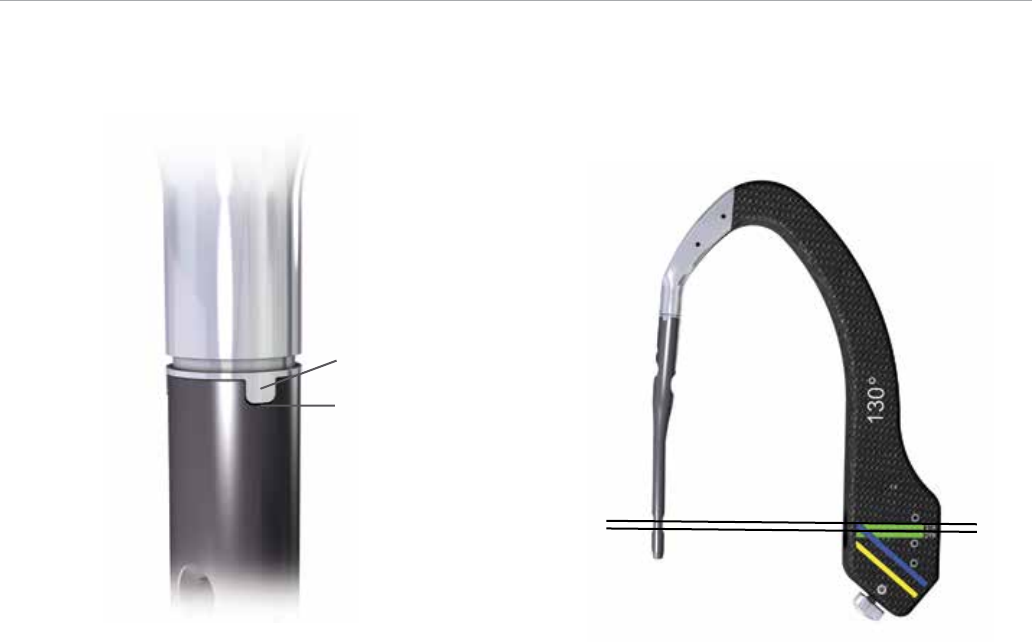
Figure 13A Figure 13B
Nail Slot
Jig Tab
Alignment of distal
targeting
When assembling the nail to the insertion jig, ensure that
the jig tabs align with the slots on the nail so that the nail
fully seats in the targeting jig (Figure 13A). Once the nail is
fully seated, securely tighten the jig bolt using the jig bolt
driver
Note: If it is dicult to attach the nail to the jig, double-
check that the nail and jig are identied with the same
angle. The nail will only align with the jig if they have the
same neck-shaft angle.
Check the assembly prior to nail introduction. Pass the
lag screw sheath through the targeting jig. A properly
assebled nail and jig will allow the lag screw drill to be
directed through the sleeve and through the center of the
lag screw hole in the nail.
When using a short (180 mm) nail, conrm the targeting
alignment of the distal interlocking screws using the green
sheaths and drill bits in the same manner (Figure 13B).
14
AFFIXUS Hip Fracture Nail
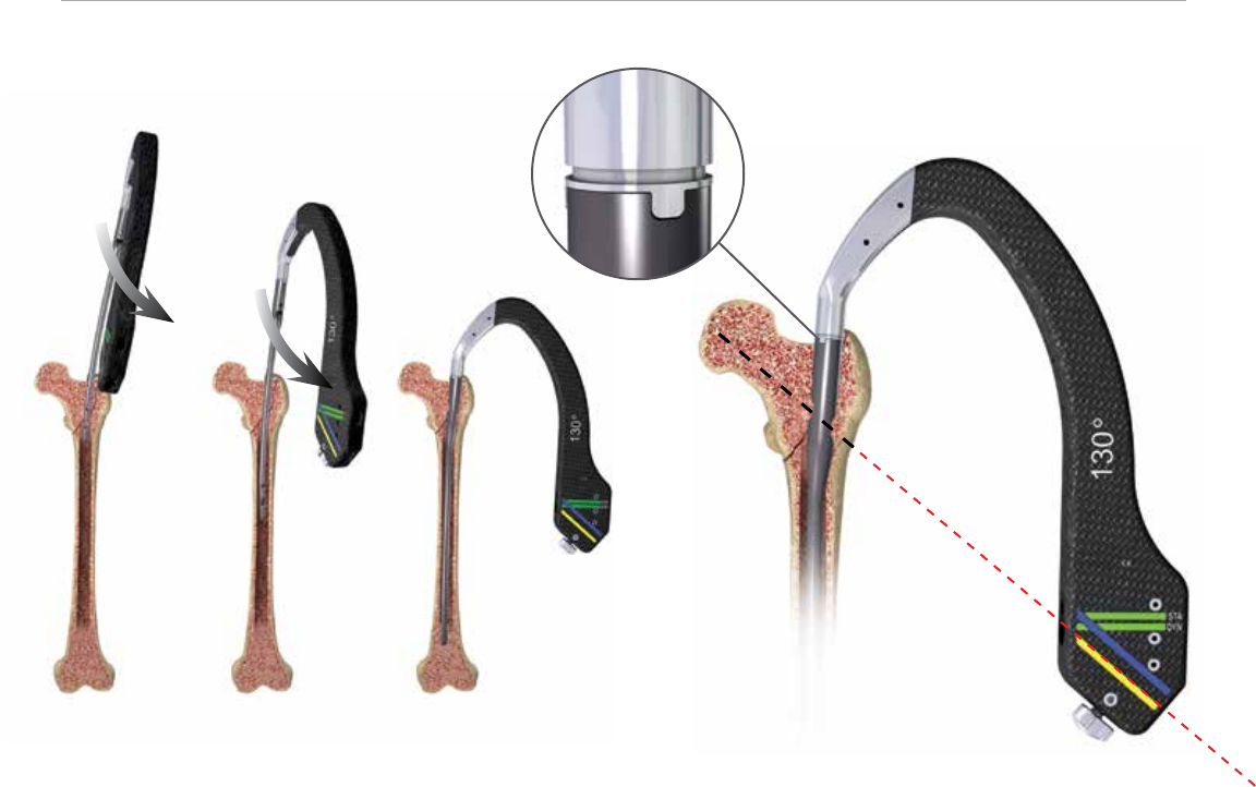
Figure 14 Figure 15
Nail Insertion
I
nsert the nail by hand over the 3 mm ball nose guide wire
into the medullary canal. Take care not to strike the jig or
targeting arm with the mallet. A curved impaction tool is
included in the set and is meant to be used for gentle taps
of the mallet to ne tune the nal seating of the nail.
Note:
The insertion jig should not be hammered on.
It may be helpful to preliminarily insert the trochanteric
nail utilizing its bow to facilitate clearance of the medial
femoral cortex of the proximal fragment. To do this, rotate
the insertion jig anteriorly (toward the ceiling). In this
position the distal bend in the nail will be angled laterally
to aid in passing the nail through the greater trochanteric
entry site, and avoid medial cortical penetration.
As the nail passes the medial cortex of the proximal
fragment, slowly derotate the jig handle into the usual
lateral position, so that the anterior bow of the nail now
corresponds with the anterior bow of the femur (Figure 14).
If the nail requires substantial force to advance, remove it
and ream an additional millimeter. Avoid excessive force
when inserting the nail. Advance the nail until the lag screw
aligns to the desired position into the femoral head and
neck to allow ideal placement of the lag screw (Figure 15).
Maintenance of reduction must be conrmed prior to lag
screw insertion. If the reduction has shifted to a suboptimal
position, further hip adduction, traction, and rotational
adjustments can be made prior to lag screw placement.
Remove the ball nose guide wire.
15
Proximal Locking
Figure 16A Figure 16B
Lag Screw Sheath
Lag Screw
3.2 mm sleeve
Lag Screw Trochar
Lag Screw Guide Pin Introduction
I
nsert the lag screw sheath assembly (lag screw sheath, lag
screw trochar, lag screw 3.2 mm sleeve) through the lag
screw hole in the jig. Pass the trochar through the sheath
and make an appropriate skin incision where the trochar
contacts the skin. Advance the trochar through the tissue
until the tip is seated against the lateral femoral cortex and
conrm with uoroscopy. The trochar may be impacted
into the lateral cortex with a mallet to create a starting
point for the guide pin and minimize migration during
insertion (Figure 16A).
Remove the trochar and maintain the lag screw sheath
position against the lateral femoral cortex.
Note: At the distal end of the jig assembly, the jig knob can
be tightened to secure the position of the lag screw sheath
to maintain contact against the lateral femoral cortex.
Introduce the 3.2 mm guide pin into the 3.2 mm sleeve and
drill into position under uoroscopic guidance. Check the
guide pin position within the center of the femoral head
and neck in both AP and lateral planes. Advance the guide
pin to a distance within 5 mm from the subchondral bone
(Figure 16B).
Note: If at any time a guide pin is bent, replace it
immediately.
16
AFFIXUS Hip Fracture Nail
Figure 17
Fluoroscopic true lateral of the
proximal femur with insertion jig
Figure 18A
Figure 18B
Goal Post Technology
The Goal Post Technology is designed to facilitate
visualization of the femoral neck on the lateral view in order
to more accurately place the guide pin for the lag screw.
The anterior and posterior metal posts on the proximal
aspect of the insertion jig allow for an unobstructed
uoroscopic view down to the base of the femoral neck
(Figure 17) and assist with ne tuning of the guide pin
before it is fully seated in the femoral head.
Lag Screw Length Selection
Before selecting a lag screw length, verify that the lag
screw sheath and 3.2 mm sleeve are in place and fully
seated against the lateral femoral cortex.
• The depth gauge seats against the lag screw sheath, not
the 3.2 mm sleeve
• The system measures to the tip of the guide pin
• The measurement represents the length of a lag screw
that begins at the end of the lag screw sheath and
terminates at the tip of the guide pin (Figure 18A and 18B)
17
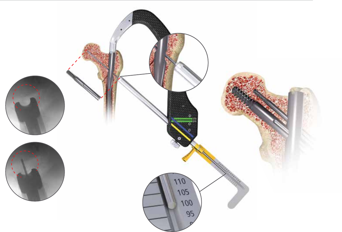
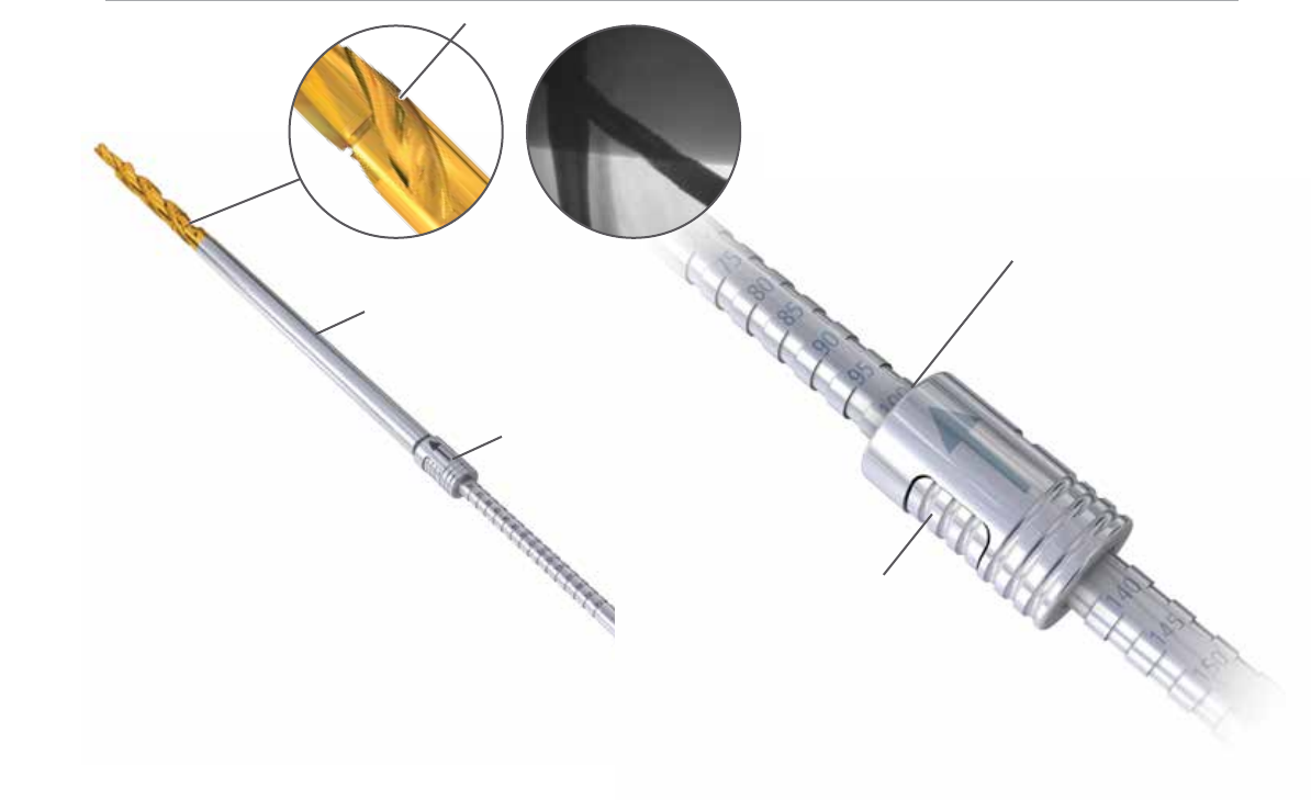
Figure 19A
Measurements taken
here, i.e., 100 mm
Push button control
Figure 19B
Lag Screw Drill
Notch
Depth Stop
Depth Stop Adjustment
Adjust the depth stop on the lag screw drill to the desired
depth. The measurement on the depth stop should be
set to the depth measured by the lag screw depth gauge
(Figure 19A).
Adjust the depth stop by pushing in the button and sliding
the stop forward or backward until desired depth is seen
on the end of the depth stop closest to the gold drill bit tip
(Figure 19B).
Note: There is a “notch” on the lag screw drill that is
visible under uoroscopy; this “notch” references 100 mm
(Figure 19A).
Lag Screw Drilling and Tapping
Advance the lag screw drill over the guide pin and drill to
the desired depth. Use uoroscopy to conrm the position
of the lag screw drill and that the guide pin is not advanced
into the hip joint or acetabulum by the drill.
If the bone is particularly dense, use the cannulated tap to
cut a thread for the lag screw.
Note: There is a guide pin repositioning tool to aid
inreinserting the guide pin if it backs out with removal of
the lag screw drill.
18
AFFIXUS Hip Fracture Nail
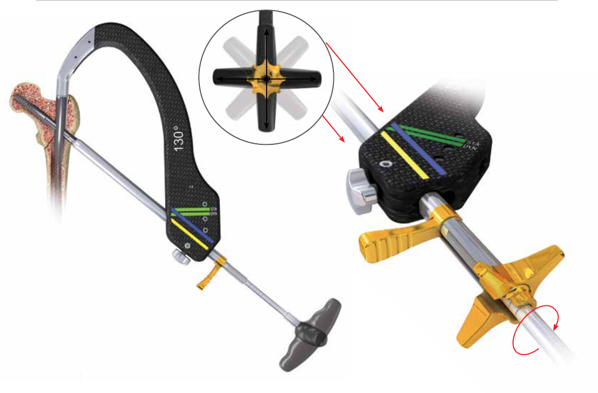
Figure 21
Figure 20
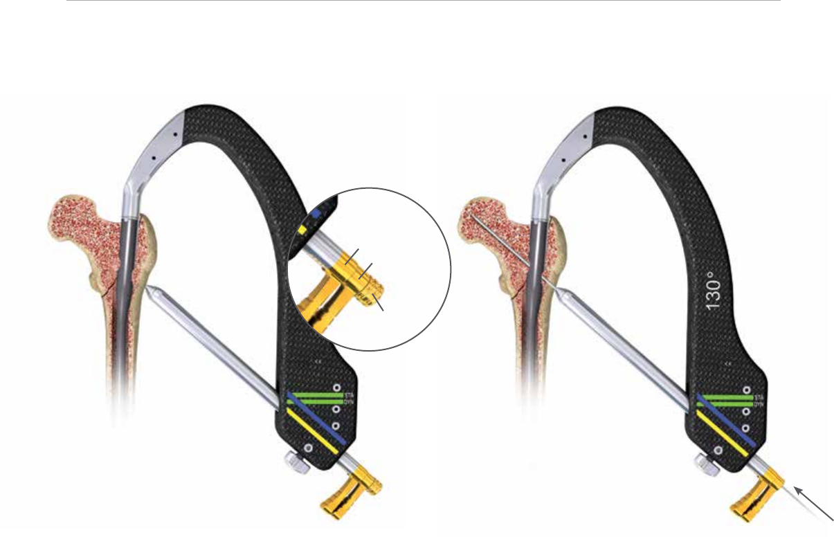
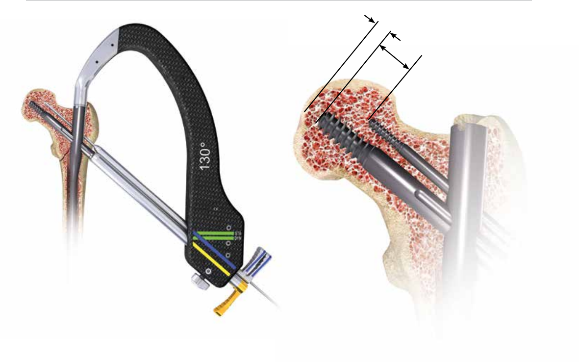
Lag Screw Insertion
Insert the lag screw coupling rod through the lag screw
driver and position the selected lag screw on the end of
the lag screw driver. Tighten the coupling rod to secure the
lag screw to the driver.
Advance the lag screw manually into the femoral neck and
head over the guide pin. Conrm the terminal position of
the lag screw with uoroscopy, with a goal of seating the
screw between 5 and 10 mm from the subchondral bone.
The handle of the lag screw driver must be positioned
either parallel or perpendicular to the targeting jig when
the lag screw has been advanced to the desired depth
(Figure 20). This will ensure that the set screw will engage
one of the grooves of the lag screw.
Fracture Compression
Compression of the intertrochanteric component of
the fracture, if desired, can be achieved by utilizing the
compression wheel. Once the lag screw has been fully
seated, release traction from the leg and rmly seat the
lag screw sheath against the lateral cortex. Conrm that
the sheath is tightly secured in the jig by tightening the jig
knob, and place the compression wheel on the lag screw
driver and advance against the lateral side of the sheath. In
osteoporotic bone, care should be taken to avoid pulling
the lag screw out of the femoral head with this technique
(Figure 21).
Note: Hash marks on lag screw driver represent 5 mm
intervals. It is recommended that no more than 4-6 mm
of compression is applied and should be applied prior to
placing the Anti-Rotation (AR) screw.
19
Figure 22A
Figure 22B
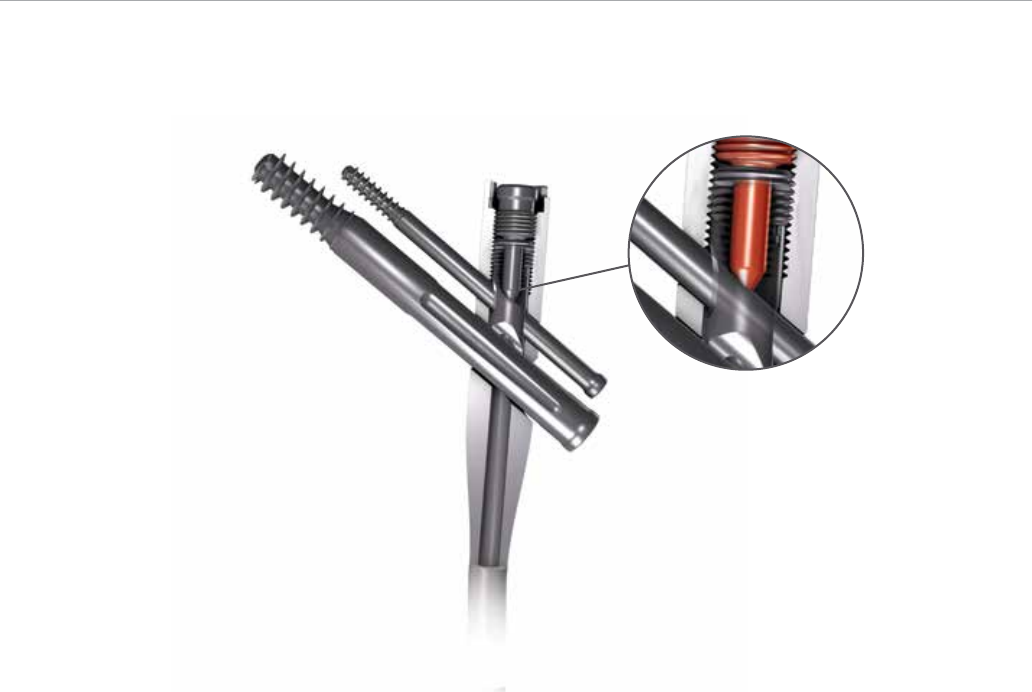
Cross section of set screw en-
gaging lag screw
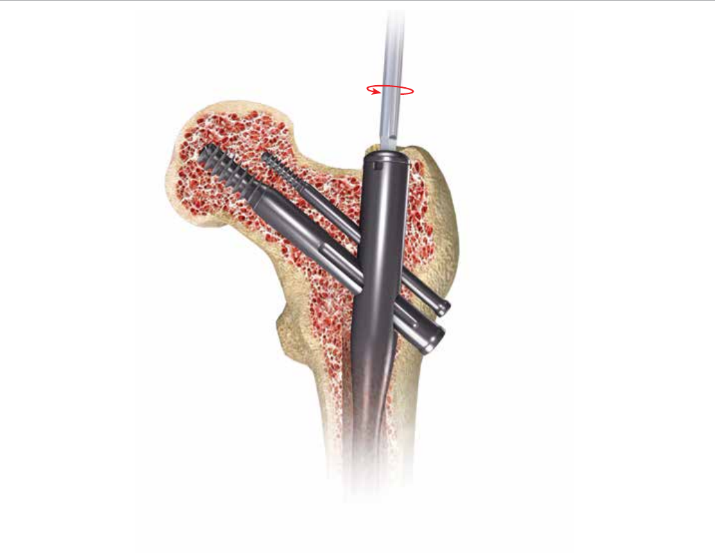
Lag Screw Fixation
The set screw is pre-loaded in the nail. Using the 5 mm set
screw hex driver, engage the set screw and advance in a
clockwise direction 2 to 3 full rotations until the set screw
contacts the lag screw in one of the four lag screw grooves
(Figure 22A & 22B).
To conrm proper position of the set screw, gently
attempt to rotate the lag screw both clockwise and
counterclockwise. If there is rm resistance and the lag
screw will not rotate, the set screw has properly engaged
the lag screw grooves. However, if you are able to rotate
the lag screw, the set screw has not engaged a groove and
the lag screw handle should be realigned and the set screw
tightened again.
The set screw may be backed o one-quarter turn to allow
dynamic compression of the lag screw in the nail, while still
providing rotational control of the lag screw.
Note: The set screw can be engaged before or after
inserting the AR screw (if the AR screw is to be used). The
AR screw will align through an oblong hole within the set
screw.
20
AFFIXUS Hip Fracture Nail
Figure 23
Anti-rotation (AR) Guide Pin and Screw
Placement (optional)
This system allows multiple techniques for placement of an
anti-rotation (AR) screw if desired.
• The AR screw may be inserted either before or after the
lag screw is placed, based upon surgeon preference and
the fracture pattern.
• The surgeon has the option to place a guide pin through
the AR hole to provisionally stabilize the fracture during
lag screw placement, or he/she may choose to use an AR
screw. The guide pin used through the AR hole is also
useful to assist in stabilizing the femoral neck and head
segment during lag screw placement to resist rotation
around the axis of the femoral neck. Once the lag screw
has been placed and secured, the surgeon may choose to
remove the guide pin from the AR hole and place a screw
in this position to provide further rotational control.
Place the AR screw sheath and trochar through the AR
hole in the insertion jig. Make a small incision where the
trochar meets the skin and advance the trochar to the
lateral aspect of the femoral cortex. Alternatively, in cases
where the lag screw has already been inserted, extend
the incision for the lag screw proximally to allow the AR
screw sheath and trochar to be seated against the femur
(Figure 23).
Note: When the anti-rotation and lag screw sheaths are
seated at the same time, they must be rotated so the
groove on the lag screw sheath faces the anti-rotation
screw sheath (so the colored handles are 180 degree to
each other) in order to allow both sheaths to fully seat
(Figure 23).
21
Figure 25
Figure 24
15 – 20 mm
5 – 10 mm
Remove the trochar and insert the AR 3.2 mm sleeve. Insert
the 3.2 mm guide pin and advance into desired position. It
is recommended to leave the AR guide pin 15-20 mm from
the subchondral bone (Figure 24).
Note: In cases where very dense cortical bone is
encountered, the cortex may be opened up with the anti-
rotation screw drill prior to advancing the 3.2 mm guide
pin to prevent the guide pin from “walking” up the lateral
cortex.
Remove the guide pin and 3.2 mm sleeve. Conrm that the
screw sheath is advanced against the lateral femoral cortex
and use the AR drill to drill to the desired depth. Measure
the length of the desired screw by reading the depth of the
AR drill against the screw sheath.
Note: It is recommended that the tip of the AR screw be
15-20 mm shorter than the lag screw to avoid perforation
of the femoral head (Figure 25).
22
AFFIXUS Hip Fracture Nail
Figure 26
Select an AR screw of the desired length. Place the AR
screw on the 3.5 mm hex driver and manually insert the
screw into the femur through the AR screw sheath.
Advance until the tip of the screw reaches the desired
depth and conrm with uoroscopy. The screwdriver and
sheath may now be removed.
Securing the AR Screw (optional)
The AR screw may be secured with an impinging end cap
that is inserted through the end of the nail.
Note: The impinging end cap will make the AR screw a
static construct and is recommended to only be used when
the lag screw is also xed in a static position (this can be
achieved by not backing o the pre-loaded set
screw a quarter turn). Otherwise there is risk of creating
the Z-eect.
It is recommended to only lock the AR screw in instances
in which the set screw has been left fully engaged into the
lag screw, thus preventing any collapse of the 10.5 mm
compression screw (Figure 26).
The impinging end cap may be utilized at the end of
the case, after the set screw for the lag screw has been
tightened, and the insertion jig has been removed.
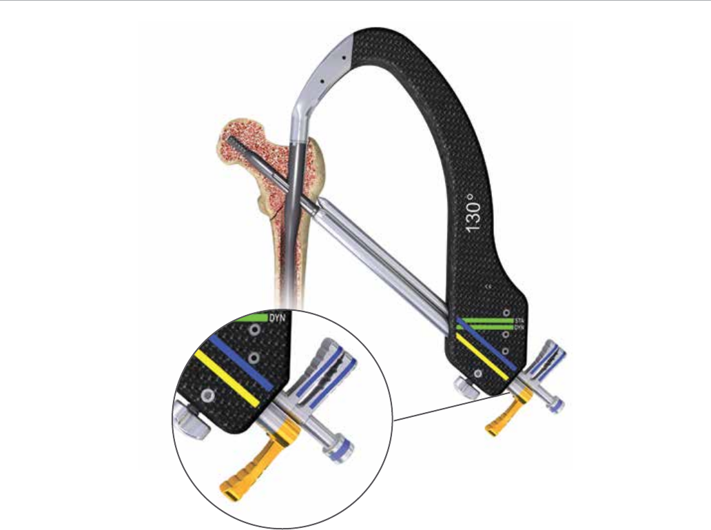
23
Distal Locking
Figure 27
Figure 28
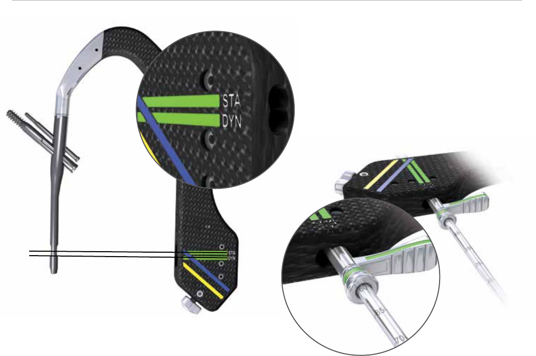
Distal Locking (short nails)
The short nail may be locked either statically, dynamically,
or left unlocked based on the particular fracture pattern
and stability (Figure 27).
Pass the distal screw sheath and trochar through the hole
labeled “static” on the insertion jig and advance to the
lateral femoral cortex. Remove the trochar and use the
distal screw drill sleeve and 4.3 mm graduated drill bit. Drill
until the far cortex is either reached or penetrated. The drill
is calibrated and may be used to determine screw length
by reading the depth o the end of the distal screw drill
sleeve (Figure 28).
An optional distal screw depth gauge is available to
conrm screw length. This gauge measures o of the
lateral side of the 4.3 mm distal screw drill sleeve.
Select a 5.0 mm diameter screw of the desired depth and
use the 3.5 mm hex driver long to introduce the screw
through the screw sheath and advance until it is fully
seated against the lateral cortex.
Repeat the above steps for dynamic locking, except pass
the distal screw sheath and trochar through the hole
labeled “dynamic” on the insertion jig.
Note: Maintain contact of the drill sheath on the lateral
femoral cortex to ensure accurate measurement of the
distal locking screw. Verify screw position using AP and
lateral uoroscopy imaging.
Note: There are two 4.3 mm drill bits available. Use the
long bit when drilling through the jig assembly and use the
short bit when performing the freehand approach.
24
AFFIXUS Hip Fracture Nail
Figure 29 Figure 30
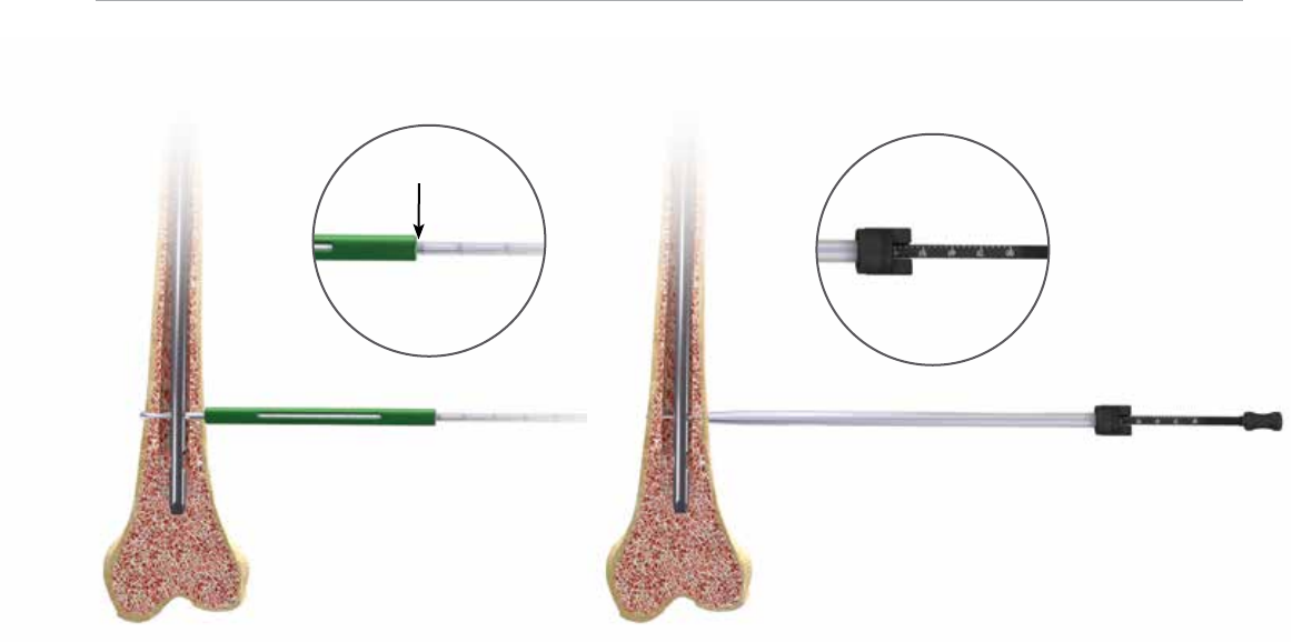
Distal Locking (long nails)
Prior to locking the distal screw(s), check femoral length
and rotation under uoroscopy. Distal locking of long
nails should be conducted using the standard image
intensication freehand technique.
Option 1
Using the short 4.3 mm graduated drill and the 4.3 mm drill
measuring sleeve, drill until the far cortex is either reached
or penetrated. Verify the drill bit position uoroscopically
prior to taking any measurements. Read the calibration
directly o of the 4.3 mm graduated drill by using the
drill measuring sleeve. The measurement should be taken
from the end of the measuring sleeve, closest to the power
source (Figure 29).
Option 2
Using the short 4.3 mm graduated drill, drill until the far
cortex is either reached or penetrated. Remove the 4.3 mm
graduated drill and measure using the distal screw depth
gauge. Ensure that the sheath of the distal screw depth
gauge is fully seated on the bone (Figure 30).
Remove the drill bit and advance the 5.0 mm screw using
the solidlok screwdriver or 3.5 mm hex driver. Repeat the
above steps for additional screw placement.
25
Figure 31
End Cap Placement
End Cap Placement (optional)
Unscrew the jig bolt that connects the insertion jig to
the end of the nail using the jig bolt driver. Remove the
insertion jig and use uoroscopy to determine the length
of the end cap desired, with a goal of leaving the proximal
aspect of the end cap ush with the tip of the greater
trochanter.
Attach the end cap to the 5 mm end cap hex driver and
insert into the end of the nail. Tighten the end cap by
turning clockwise until the end cap fully seats against the
top of the nail. If xation of the AR screw is desired, select
the impinging in cap instead of the standard end cap
(Figure 31).
26
AFFIXUS Hip Fracture Nail
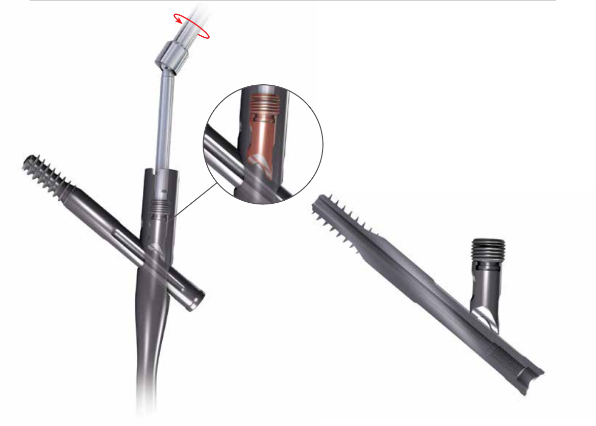
Implant Removal
Slotted Hammer Sliding Hammer
Figure 33
Figure 32
Identify the proximal end of the nail by opening the same
incision used for insertion of the implant. Clear bone from
the proximal end of nail if necessary or remove the end cap
(if present) with the 5 mm end cap hex driver.
• Remove the distal screw using the 3.5 mm hex driver
after making an incision through the scar site.
• If an AR screw is present, use the AR screw removal tool
to extract the AR screw prior to loosening the set screw.
Reminder: The set screw should NOT be loosened prior to
removing the AR screw.
• Use the 5 mm set screw hex driver to loosen the set screw.
This will allow the lag screw to rotate counterclockwise.
Typically 2 to 3 full rotations is all that is necessary.
• Attach the lag screw driver and coupling rod to the lateral
end of the lag screw and conrm that it will freely rotate
in a counterclockwise direction.
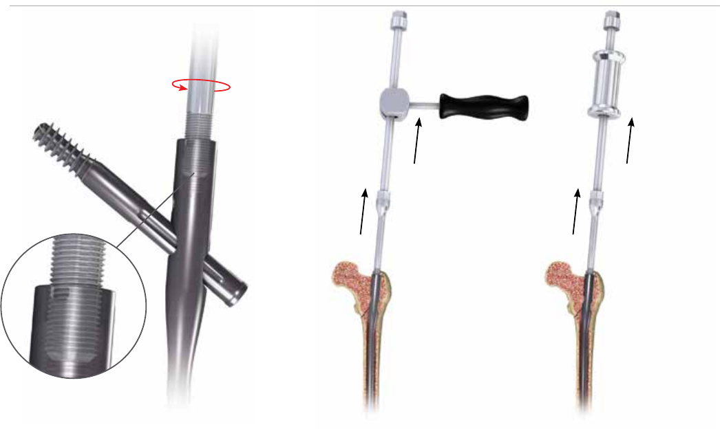
• Insert the cannulated extraction bolt into the proximal
end of the nail (Figure 32).
Note: If the extraction bolt is not threading into the
proximal end of the nails, the set screw may have been
backed out too far and should be advanced clockwise.
• Attach the extraction rod to the extraction bolt.
• Remove the lag screw by turning counterclockwise and
then remove the distal interlocking screws.
• Use the sliding hammer or slotted mallet over the
extraction rod and back slap to remove the nail (Figure
33).
Note: It is recommended that the extraction rod and
bolt be attached to the nail prior to removing the nal
screw to prevent the nail from being forced down the
intramedullary canal.
Note: The conical extractor is designed to cross thread
onto the nail, and it is recommended that it is tightly
secured to the nail before the lag screw is removed to
prevent the nail from rotating in the femoral canal.
27
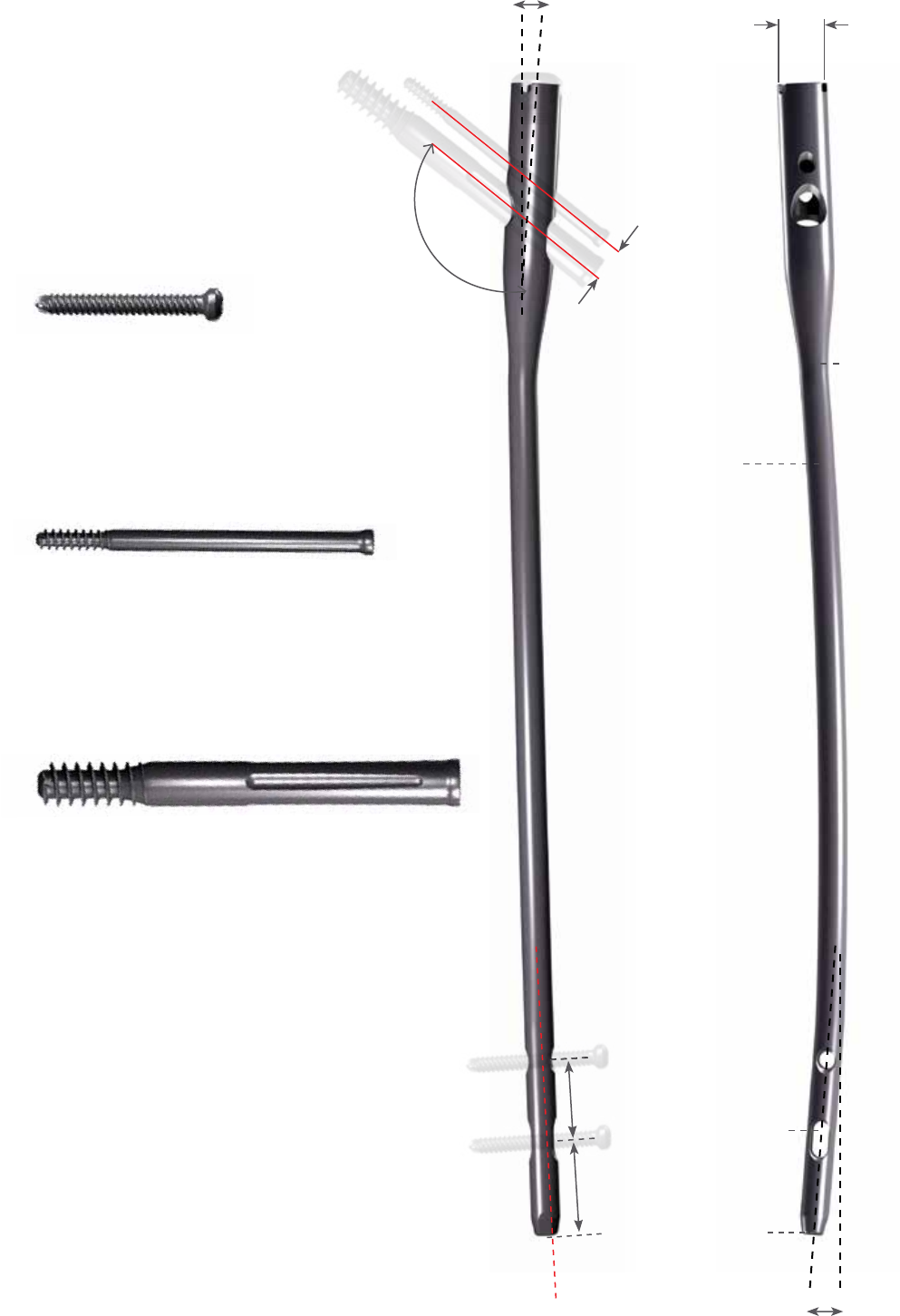
Implant Diagrams
Distal Screw, 20-80 mm
Sterile: 8145-50-0XX
• Diameter 5.0 mm
• 3.5 mm Hex Driver Socket
Anti-rotation Screw, 50-110 mm
Sterile: 8145-01-XXX
• Diameter 5.0 mm
• 3.6 mm Hex Driver Socket
• 3 mm Inner Thread for Removal
• Self Tapping Threads
Lag Screw, 70-130 mm
Sterile: 8145-10-XXX
• Diameter 10.5 mm
• Reverse Buttress Thread
• 6.5 mm Square Driver Socket
• Self Tapping Threads
125˚
&
130˚
30 mm
25 mm
12.76 mm
Diameter 9.0 mm
Diameter 11.0 mm
Diameter 13.0 mm
Diameter 15.0 mm
1.8 M Radius
of Curvature
6 mm
Dynamization
Range
10° Proximal
Anteversion
15.6 mm Proximal
Diameter
3˚
4˚

28
AFFIXUS Hip Fracture Nail
Product Ordering Information
Rights Lefts Rights Lefts
Long Nails, 9 mm, 125° Long Nails, 9 mm, 130°
8143-09-260 8144-09-260 125° 9 mm X 260 mm 8145-09-260 8146-09-260 130° 9 mm X 260 mm
8143-09-280 8144-09-280 125° 9 mm X 280 mm 8145-09-280 8146-09-280 130° 9 mm X 280 mm
8143-09-300 8144-09-300 125° 9 mm X 300 mm 8145-09-300 8146-09-300 130° 9 mm X 300 mm
8143-09-320 8144-09-320 125° 9 mm X 320 mm 8145-09-320 8146-09-320 130° 9 mm X 320 mm
8143-09-340 8144-09-340 125° 9 mm X 340 mm 8145-09-340 8146-09-340 130° 9 mm X 340 mm
8143-09-360 8144-09-360 125° 9 mm X 360 mm 8145-09-360 8146-09-360 130° 9 mm X 360 mm
8143-09-380 8144-09-380 125° 9 mm X 380 mm 8145-09-380 8146-09-380 130° 9 mm X 380 mm
8143-09-400 8144-09-400 125° 9 mm X 400 mm 8145-09-400 8146-09-400 130° 9 mm X 400 mm
8143-09-420 8144-09-420 125° 9 mm X 420 mm 8145-09-420 8146-09-420 130° 9 mm X 420 mm
8143-09-440 8144-09-440 125° 9 mm X 440 mm 8145-09-440 8146-09-440 130° 9 mm X 440 mm
8143-09-460 8144-09-460 125° 9 mm X 460 mm 8145-09-460 8146-09-460 130° 9 mm X 460 mm
Long Nails, 11 mm, 125° Long Nails, 11 mm, 130°
8143-11-260 8144-11-260 125° 11 mm X 260 mm 8145-11-260 8146-11-260 130° 11 mm X 260 mm
8143-11-280 8144-11-280 125° 11 mm X 280 mm 8145-11-280 8146-11-280 130° 11 mm X 280 mm
8143-11-300 8144-11-300 125° 11 mm X 300 mm 8145-11-300 8146-11-300 130° 11 mm X 300 mm
8143-11-320 8144-11-320 125° 11 mm X 320 mm 8145-11-320 8146-11-320 130° 11 mm X 320 mm
8143-11-340 8144-11-340 125° 11 mm X 340 mm 8145-11-340 8146-11-340 130° 11 mm X 340 mm
8143-11-360 8144-11-360 125° 11 mm X 360 mm 8145-11-360 8146-11-360 130° 11 mm X 360 mm
8143-11-380 8144-11-380 125° 11 mm X 380 mm 8145-11-380 8146-11-380 130° 11 mm X 380 mm
8143-11-400 8144-11-400 125° 11 mm X 400 mm 8145-11-400 8146-11-400 130° 11 mm X 400 mm
8143-11-420 8144-11-420 125° 11 mm X 420 mm 8145-11-420 8146-11-420 130° 11 mm X 420 mm
8143-11-440 8144-11-440 125° 11 mm X 440 mm 8145-11-440 8146-11-440 130° 11 mm X 440 mm
8143-11-460 8144-11-460 125° 11 mm X 460 mm 8145-11-460 8146-11-460 130° 11 mm X 460 mm
Long Nails, 13 mm, 125° Long Nails, 13 mm, 130°
8143-13-260 8144-13-260 125° 13 mm X 260 mm 8145-13-260 8146-13-260 130° 13 mm X 260 mm
8143-13-280 8144-13-280 125° 13 mm X 280 mm 8145-13-280 8146-13-280 130° 13 mm X 280 mm
8143-13-300 8144-13-300 125° 13 mm X 300 mm 8145-13-300 8146-13-300 130° 13 mm X 300 mm
8143-13-320 8144-13-320 125° 13 mm X 320 mm 8145-13-320 8146-13-320 130° 13 mm X 320 mm
8143-13-340 8144-13-340 125° 13 mm X 340 mm 8145-13-340 8146-13-340 130° 13 mm X 340 mm
8143-13-360 8144-13-360 125° 13 mm X 360 mm 8145-13-360 8146-13-360 130° 13 mm X 360 mm
8143-13-380 8144-13-380 125° 13 mm X 380 mm 8145-13-380 8146-13-380 130° 13 mm X 380 mm
8143-13-400 8144-13-400 125° 13 mm X 400 mm 8145-13-400 8146-13-400 130° 13 mm X 400 mm
8143-13-420 8144-13-420 125° 13 mm X 420 mm 8145-13-420 8146-13-420 130° 13 mm X 420 mm
8143-13-440 8144-13-440 125° 13 mm X 440 mm 8145-13-440 8146-13-440 130° 13 mm X 440 mm
8143-13-460 8144-13-460 125° 13 mm X 460 mm 8145-13-460 8146-13-460 130° 13 mm X 460 mm
Long Nails, 15 mm, 130°
8145-15-320 8146-15-320 130° 15 mm X 320 mm
8145-15-360 8146-15-360 130° 15 mm X 360 mm
8145-15-400 8146-15-400 130° 15 mm X 400 mm
8145-15-440 8146-15-440 130° 15 mm X 440 mm

29
Short Nails, 125°
8143-09-180 125° 9 mm X 180 mm
8143-11-180 125° 11 mm X 180 mm
8143-13-180 125° 13 mm X 180 mm
Short Nails, 130°
8145-09-180 130° 9 mm X 180 mm
8145-11-180 130° 11 mm X 180 mm
8145-13-180 130° 13 mm X 180 mm
Lag Screws
8145-10-070 LAG SCREW 10.5 mm X 70 mm
8145-10-075 LAG SCREW 10.5 mm X 75 mm
8145-10-080 LAG SCREW 10.5 mm X 80 mm
8145-10-085 LAG SCREW 10.5 mm X 85 mm
8145-10-090 LAG SCREW 10.5 mm X 90 mm
8145-10-095 LAG SCREW 10.5 mm X 95 mm
8145-10-100 LAG SCREW 10.5 mm X 100 mm
8145-10-105 LAG SCREW 10.5 mm X 105 mm
8145-10-110 LAG SCREW 10.5 mm X 110 mm
8145-10-115 LAG SCREW 10.5 mm X 115 mm
8145-10-120 LAG SCREW 10.5 mm X 120 mm
8145-10-125 LAG SCREW 10.5 mm X 125 mm
8145-10-130 LAG SCREW 10.5 mm X 130 mm
Anti-Rotation Screws
8145-01-050 A/R SCREW 50 mm
8145-01-055 A/R SCREW 55 mm
8145-01-060 A/R SCREW 60 mm
8145-01-065 A/R SCREW 65 mm
8145-01-070 A/R SCREW 70 mm
8145-01-075 A/R SCREW 75 mm
8145-01-080 A/R SCREW 80 mm
8145-01-085 A/R SCREW 85 mm
8145-01-090 A/R SCREW 90 mm
8145-01-095 A/R SCREW 95 mm
8145-01-100 A/R SCREW 100 mm
8145-01-105 A/R SCREW 105 mm
8145-01-110 A/R SCREW 110 mm
Distal Screws
8145-50-020 CORTICAL BONE SCR 5.0 mm X 20 mm
8145-50-022 CORTICAL BONE SCR 5.0 mm X 22 mm
8145-50-024 CORTICAL BONE SCR 5.0 mm X 24 mm
8145-50-026 CORTICAL BONE SCR 5.0 mm X 26 mm
8145-50-028 CORTICAL BONE SCR 5.0 mm X 28 mm
8145-50-030 CORTICAL BONE SCR 5.0 mm X 30 mm
8145-50-032 CORTICAL BONE SCR 5.0 mm X 32 mm
8145-50-034 CORTICAL BONE SCR 5.0 mm X 34 mm
8145-50-036 CORTICAL BONE SCR 5.0 mm X 36 mm
8145-50-038 CORTICAL BONE SCR 5.0 mm X 38 mm
8145-50-040 CORTICAL BONE SCR 5.0 mm X 40 mm
8145-50-042 CORTICAL BONE SCR 5.0 mm X 42 mm
8145-50-044 CORTICAL BONE SCR 5.0 mm X 44 mm
8145-50-046 CORTICAL BONE SCR 5.0 mm X 46 mm
8145-50-048 CORTICAL BONE SCR 5.0 mm X 48 mm
8145-50-050 CORTICAL BONE SCR 5.0 mm X 50 mm
8145-50-052 CORTICAL BONE SCR 5.0 mm X 52 mm
8145-50-054 CORTICAL BONE SCR 5.0 mm X 54 mm
8145-50-056 CORTICAL BONE SCR 5.0 mm X 56 mm
8145-50-058 CORTICAL BONE SCR 5.0 mm X 58 mm
8145-50-060 CORTICAL BONE SCR 5.0 mm X 60 mm
8145-50-065 CORTICAL BONE SCR 5.0 mm X 65 mm
8145-50-070 CORTICAL BONE SCR 5.0 mm X 70 mm
8145-50-075 CORTICAL BONE SCR 5.0 mm X 75 mm
8145-50-080 CORTICAL BONE SCR 5.0 mm X 80 mm
End Caps
8145-03-000 END CAP FLUSH
8145-03-005 END CAP 5 mm
8145-03-101 IN CAP FLUSH IMPINGING
30
AFFIXUS Hip Fracture Nail
Product Ordering Information
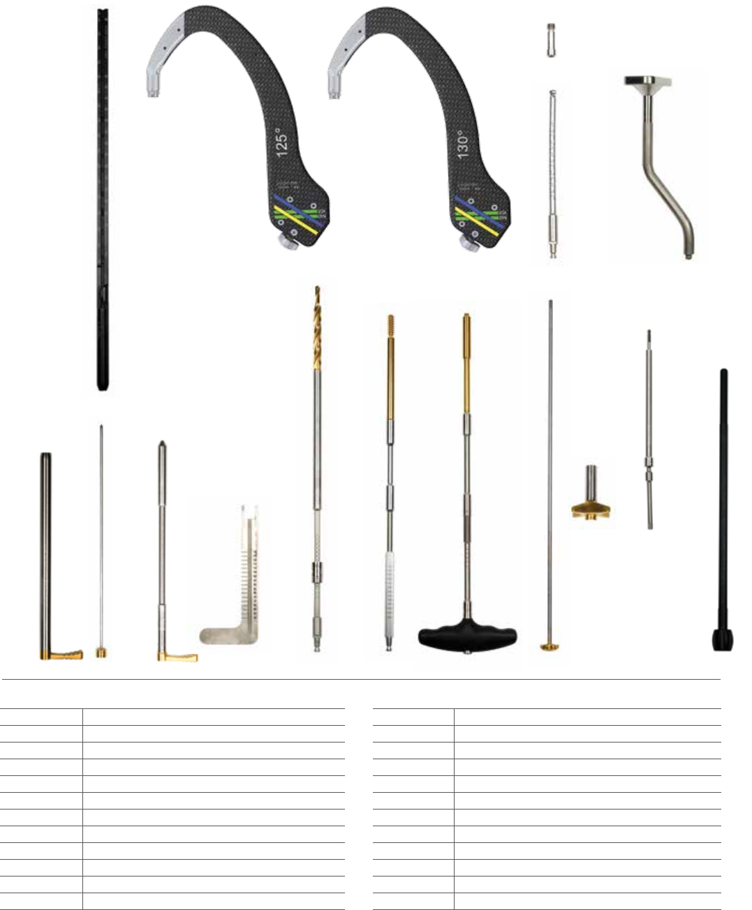
1 2 3 4 5 6
8 9 10 11
7
* Products are disposable.
Reduction
9030-03-004 Threaded Guide Pin 3.2 mm*
2810-01-080 Ball Nose Guidewire 80 cm*
2810-01-100 Ball Nose Guidewire 100 cm*
2810-01-001 6 - Pistol Guidewire Gripper
2810-01-026 7 - Guidewire Pusher
2810-01-007 8 - Long Reduction Tool
2142-02-012 9 - Ball Spike Pusher
2112-01-003 10 - Bone Hook
2141-19-000 11 - Femoral Bone Clamp
2810-01-175 3.2 mm x 444 mm Threaded Guide Pin Sterile*
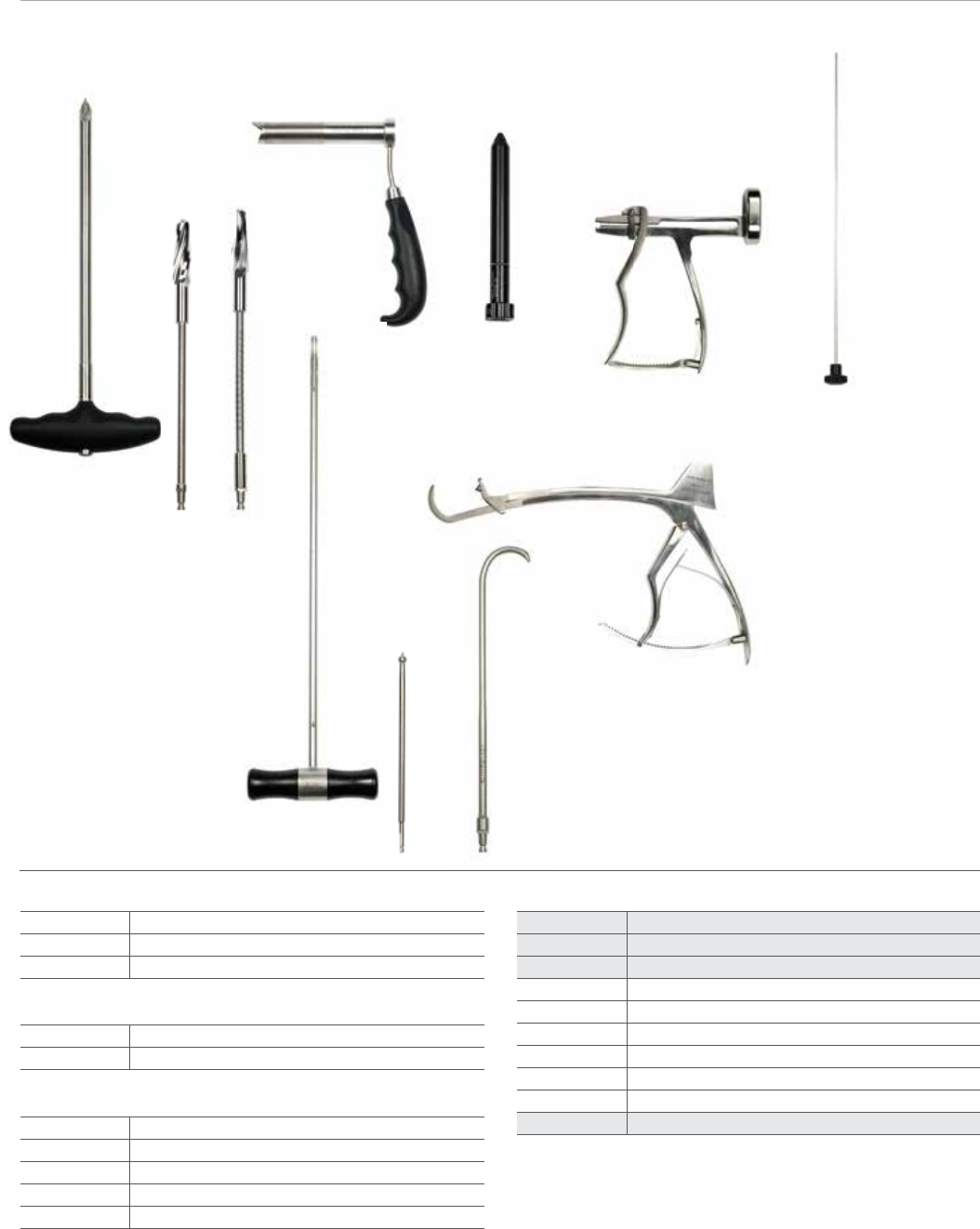
General
2810-01-004 T-Handle Hudson
8261-66-000 Ratchet Screwdriver Handle Small
Entry
2112-01-100 1 - AWL
2112-01-102 2 - Entry Reamer Solid Shaft
2112-01-103 3 - Entry Reamer Flexible Shaft
2112-01-104 4 - Entry Portal
2810-13-004 5 - Entry Portal Trochar
AFFIXUS Hip Fracture Nail System
2112-01-000 Instrument Case 2
2112-01-001 Instrument Case 1
2112-01-800 Full Anatomy (FA) Instrument Case
31
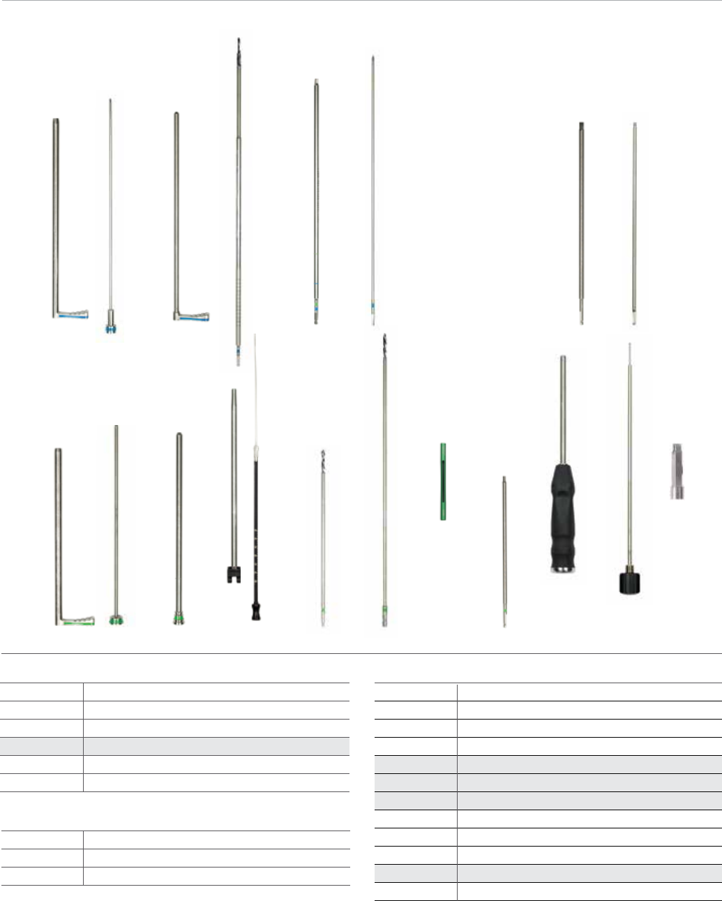
12
13 14
15
16 17
18 19 20 21 22 23 24 25 26 27 28
Nail Insertion
2112-01-106 12 - Nail Depth Gauge
2112-01-200 13 - Insertion jig 125°
2112-01-207 FA Insertion jig 125°
2112-01-201 14 - Insertion jig 130°
2112-01-208 FA Insertion jig 130°
2112-01-202 15 - Insertion jig bolt
2112-01-209 FA Insertion jig bolt
2112-01-205 Jig knob
2112-01-206 Jig knob retainer
2810-13-037 16 - Flexible jig bolt driver 8 mm
2810-13-006 Jig bolt driver 8 mm
2112-01-204 17 - Impaction tool
Lag Screw Placement
2112-01-300 18 - Lag Screw Sheath
2112-01-301 19 - Lag Screw Trochar
2112-01-302 20 - Lag Screw 3.2 mm Sleeve
2112-01-304 21 - Lag Screw Depth Gauge
2112-01-303 22 - Lag Screw Drill
2112-01-310 23 - Lag Screw Tap
2112-01-307 24 - Lag Screw Driver
2112-01-306 25 - Lag Screw Coupling Rod
2112-01-308 26 - Compression Wheel
2112-01-309 27 - 5 mm Hex Driver - Set Screw
2112-01-320 FA 5 mm Hex Driver - Set Screw
2112-01-312 28 - Guide Pin Positioning Tool
32
AFFIXUS Hip Fracture Nail
Product Ordering Information
29
37 38 39 40 41 42 43 44 45 46 47
30 31 32 33 34 35 36
* Products are disposable.
AR Screw Placement
2112-01-501
29 - A/R Screw Sheath
2112-01-502
30 - A/R Screw Trochar
2112-01-503
31 - A/R Screw 3.2 mm sleeve
2112-01-505
32 - A/R Screw Drill*
2112-01-504
33 - 3.5
mm
Hex Driver Long-A/R Distal Screw
2112-01-506
34 - A/R Screw Removal Tool
Distal Screw Insertion
2112-01-401
37 - Distal Screw Sheath
2112-01-402
38 - Distal Screw Trochar
2112-01-403
39 - Distal Screw Drill Sleeve
2112-01-404
40 - Distal Screw Depth Gauge
2112-01-406
41 - 4.3 mm Distal Graduated Drill Short*
2112-01-405
42 - 4.3 mm Distal Graduated Drill Long*
2112-01-410
43 - 4.3 mm Drill Measuring Sleeve*
2112-01-409
44 - 3.5 mm Hex Driver Short - Distal Screw
2810-01-020
45 - SolidLok Screwdriver Handle
2810-01-021
46 - SolidLok Driver Inner Shaft
2810-01-019
SolidLok Hex Tip 3.5 mm*
2112-01-504
33 - 3.5 mm Hex Driver Long - AR/Distal Screw
End Cap Placement
2112-01-600 35 - 5 mm Hex Driver End Cap
2112-01-601 5 mm Hex Can Driver End Cap
2112-01-602 36 - End Cap Removal Tool
33
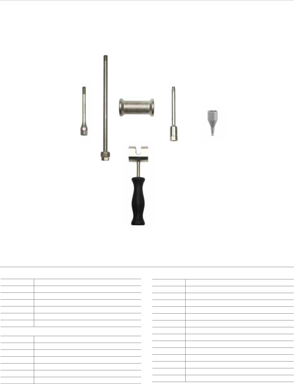
48 49
50
51
52
Extraction
2112-01-666 48 - Cannulated Extraction Bolt
1095 49 - Extraction Rod
1796 50 - Sliding Hammer Small
1096 Sliding Hammer Large
2112-01-606 51 - Slotted Mallet
2112-01-605 52 - Conical Extractor
2810-01-027 53 - 3/4 in Hex Driver
2810-04-100 10.0 mm Modular Reamer Head
2810-04-105 10.5 mm Modular Reamer Head
2810-04-110 11.0 mm Modular Reamer Head
2810-04-115 11.5 mm Modular Reamer Head
2810-04-120 12.0 mm Modular Reamer Head
2810-04-125 12.5 mm Modular Reamer Head
2810-04-130 13.0 mm Modular Reamer Head
2810-04-135 13.5 mm Modular Reamer Head
2810-04-140 14.0 mm Modular Reamer Head
2810-04-145 14.5 mm Modular Reamer Head
2810-04-150 15.0 mm Modular Reamer Head
2810-04-155 15.5 mm Modular Reamer Head
2810-04-160 16.0 mm Modular Reamer Head
2810-04-165 16.5 mm Modular Reamer Head
2810-04-170 17.0 mm Modular Reamer Head
Flexible Reamers
2810-02-400 400 mm Nitinol Modular Reamer Hudson
2810-02-470 470 mm Nitinol Modular Reamer Hudson
2810-02-015 150 mm Reamer Extension
2810-02-081 8 mm MNBLC Endcut Reamer Hudson
2810-02-091 9 mm MNBLC Endcut Reamer Hudson
2810-04-090 9.0 mm Modular Reamer Head
2810-04-095 9.5 mm Modular Reamer Head
53

This material is intended for health care professionals and the Biomet sales
force only. Distribution to any other recipient is prohibited. All content herein is
protected by copyright, trademarks and other intellectual property rights owned
by or licensed to Biomet Inc. or its aliates unless otherwise indicated. This material
must not be redistributed, duplicated or disclosed, in whole or in part, without the
express written consent of Biomet.
Check for country product clearances and reference product specic instructions
for use. For complete product information, including indications, contraindications,
warnings, precautions, and potential adverse eects, see the package insert and
Biomet’s website.
This technique was prepared in conjunction with a licensed health care professional.
Biomet does not practice medicine and does not recommend any particular
orthopedic implant or surgical technique for use on a specic patient. The surgeon
is responsible for determining the appropriate device(s) and technique(s) for each
individual patient.
Not for distribution in France.
©2014 Biomet Trauma • Form No. BMET0022.0-GBL • REV0614
Legal Manufacturer
Biomet Trauma
56 East Bell Drive
P.O. Box 587
Warsaw, Indiana 46581
USA
www.biomet.com
Authorised Representative
Biomet UK Ltd.
Waterton Industrial Estate
Bridgend, South Wales
CF31 3XA
UK
0086
Important:
This Essential Product Information does not include all of the information
necessary for selection and use of a device. Please see full labeling for all
necessary information.
The use of metallic surgical appliances (screws, plates, intramedullary nails,
compression hip screws, pins and wires) provides the orthopaedic surgeon a
means of bone xation and helps generally in the management of fractures and
reconstructive surgeries. These implants are intended as a guide to normal healing,
and are NOT intended to replace normal body structure or bear the weight of the
body in the presence of incomplete bone healing. Delayed unions or nonunions in
the presence of load bearing or weight bearing might eventually cause the implant
to break due to metal fatigue. All metal surgical implants are subjected to repeated
stress in use, which can result in metal fatigue.
Indications
The AFFIXUS Hip Fracture Nail is intended to treat stable and unstable proximal
fractures of the femur including pertrochanteric fractures, intertrochanteric fractures,
high subtrochanteric fractures and combinations of these fractures, including non-
union, malunion and tumor resections. The Long Nail system is additionally indicated
to treat pertrochanteric fractures associated with shaft fractures, pathologic fractures
in osteoporotic bone (including prophylactic use) of the trochanteric and diaphyseal
areas, impending pathological fractures, long subtrochanteric fractures, ipsilateral
femoral fractures, proximal or distal non-unions, malunions, revision procedures and
tumor resections
Contraindications:
Screws, plates, intramedullary nails, compression hip screws, pins and wires are
contraindicated in: active infection, conditions which tend to retard healing such
as blood supply limitations, previous infections, insucient quantity or quality of
bone to permit stabilization of the fracture complex, conditions that restrict the
patient’s ability or willingness to follow postoperative instructions during the healing
process, foreign body sensitivity, and cases where the implant(s) would cross open
epiphyseal plates in skeletally immature patients.
Additional Contraindication for Orthopaedic Screws and Plates only:
Cases with malignant primary or metastatic tumors which preclude adequate bone
support or screw xations, unless supplemental xation or stabilization methods
are utilized.
Additional Contraindication for Retrograde Femoral Nailing:
A history of septic arthritis of the knee and knee extension contracture with inability
to attain at least 45º of exion.
Additional Contraindications for Compression Hip Screws only:
Inadequate implant support due to the lack of medial buttress.
Warnings and Precautions:
Bone screws and pins are intended for partial weight bearing and non-weight bearing
applications. These components cannot be expected to withstand the unsupported
stresses of full weight bearing.
Adverse Events:
The following are the most frequent adverse events after xation with orthopaedic
screws, plates, intramedullary nails, compression hip screws, pins and wires:
loosening, bending, cracking or fracture of the components or loss of xation in bone
attributable to nonunion, osteoporosis, markedly unstable comminuted fractures;
loss of anatomic position with nonunion or malunion with rotation or angulation;
infection and allergies and adverse reactions to the device material. Surgeons
should take care when targeting and drilling for the proximal screws in any tibial nail
with oblique proximal screws. Care should be taken as the drill bit is advanced to
penetrate the far cortex. Advancing the drill bit too far in this area may cause injury
to the deep peroneal nerve. Fluoroscopy should be used to verify correct positioning
of the drill bit.
Additional Adverse Events for Compression Hip Screw only:
Screw cutout of the femoral head (usually associated with osteoporotic bone).
