Ampfsm User Manual
2017-03-29
User Manual: Pdf Ampfsm AMPFSM pdf kavson.co.uk
Open the PDF directly: View PDF ![]() .
.
Page Count: 2
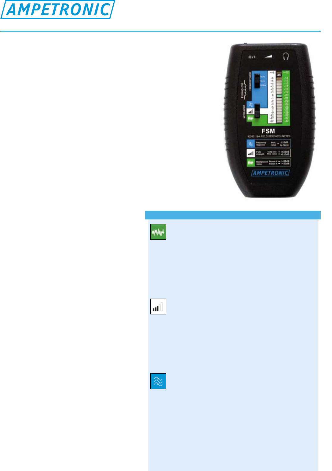
The FSM is a cost effective and simple solution for measuring, setting
up and commissioning an induction loop system to the requirements
of IEC60118-4:2006. The meter is an ergonomically designed hand
held instrument for measuring loop system performance. There are
three calibrated operational modes for the assessment of Background
Noise, Field Strength and Frequency Response as required to ensure
correct function of the loop system. The meter also doubles as a loop
listener, with a headphone output to listen to the signal in the loop.
The meter is supplied in a soft case with an audio CD with the
required test signals, and full operating instructions including a guide
to commissioning. The Ampetronic FSM can be used to monitor,
set up or commission any induction loop system regardless of the
manufacturer or type.
Features
• Simple assessment of any system to
IEC60118-4:2006
• Threemodesofoperationforthreetesttypes
• Aweightedbackgroundnoise
• Broadbandmode(50Hz-8kHz)
• Frequencyresponse(100Hz,1kHz,5kHz)
• TrueRMSdetectioncalibratedto
400mA/m=0dB
• WideviewingangleLEDdisplay
• ColourcodedLEDsforsimplereadout
• Resolutionto1dB
• Headphoneoutputwithvolumecontrol
• Ergonomic,rugged,lightweightconstruction
• TestsignalssuppliedonCD
• Softcarrycase
• 5yearwarranty
Applications include:
• Accurateset-upandcommissioning
• Systemmonitoringandmaintenance
• Sitesurveys
• CerticationtoIEC60118-4:2006
• Assessmentoffrequencylossesduetometal
• Assessmentofloopcoverageandoverspill
• Assessmentofbackgroundnoise
Datasheet
FSM – Field Strength Meter (IEC60118-4)
Operationalmodes
BackgroundNoise
To determine the level of the background magnetic field present in
the intended location for the loop system. Also used to measure
low level signals to assess overspill outside a loop system.
• Aweightedlter
• TrueRMSdetectionreferencedto400mA/m
• Scale-42to-12dB
• Audio(headphone)outputispostlterformonitoring
FieldStrength
A broad band measurement to measure field strength delivered by
the system.
• Broadbandmeasurement50Hzto8kHz
• TrueRMSdetectionreferencedto400mA/m
• Scale-22to+8dBwith1dBintervalsfrom-3to+6dB
• Suitableforusewithsinewave,pinknoise,or
combinationsignals(provided),oranyotherrealsignals
FrequencyResponse
Third octave filters for measuring performance across the required
frequency spectrum as required by IEC60118-4.
Used to confirm adequate power at high frequencies as required
for good intelligibility. Used to assess frequency dependent loss
due to metal structures, and to optimise frequency compensation.
• Thirdoctavebandsat100Hz,1kHzand5kHz
• TrueRMSdetection
• Scaleresolutionto1dB
• Forusewithpinknoiseonly(signalprovided)
• Audio(headphone)outputispostlter
Issue no UP34302-1 DISTRIBUTOR
www.ampetronic.com
sales@ampetronic.com
support@ampetronic.com
phone +44 (0)1636 610062
fax +44 (0)1636 610063
Northern Road, Newark NG24 2ET. United Kingdom
Accessories
•Softcarrypouch
•Userguide/handbook
•CommissioningCerticate(template)
•DesigningInductionLoopshandbook
•Batteries
•CDofTestSignals
3 different test signals are provided on CD to enable
the set up of any induction loop system.
Tracklist
• Combination: Pink noise with 1kHz sine
wave bursts (30 mins)
• Pink noise (30 mins)
• Sine wave (1 min)
StandardsCompliance
The FSM field strength meter and loop receiver is
CE marked to all relevant safety and EMC standards
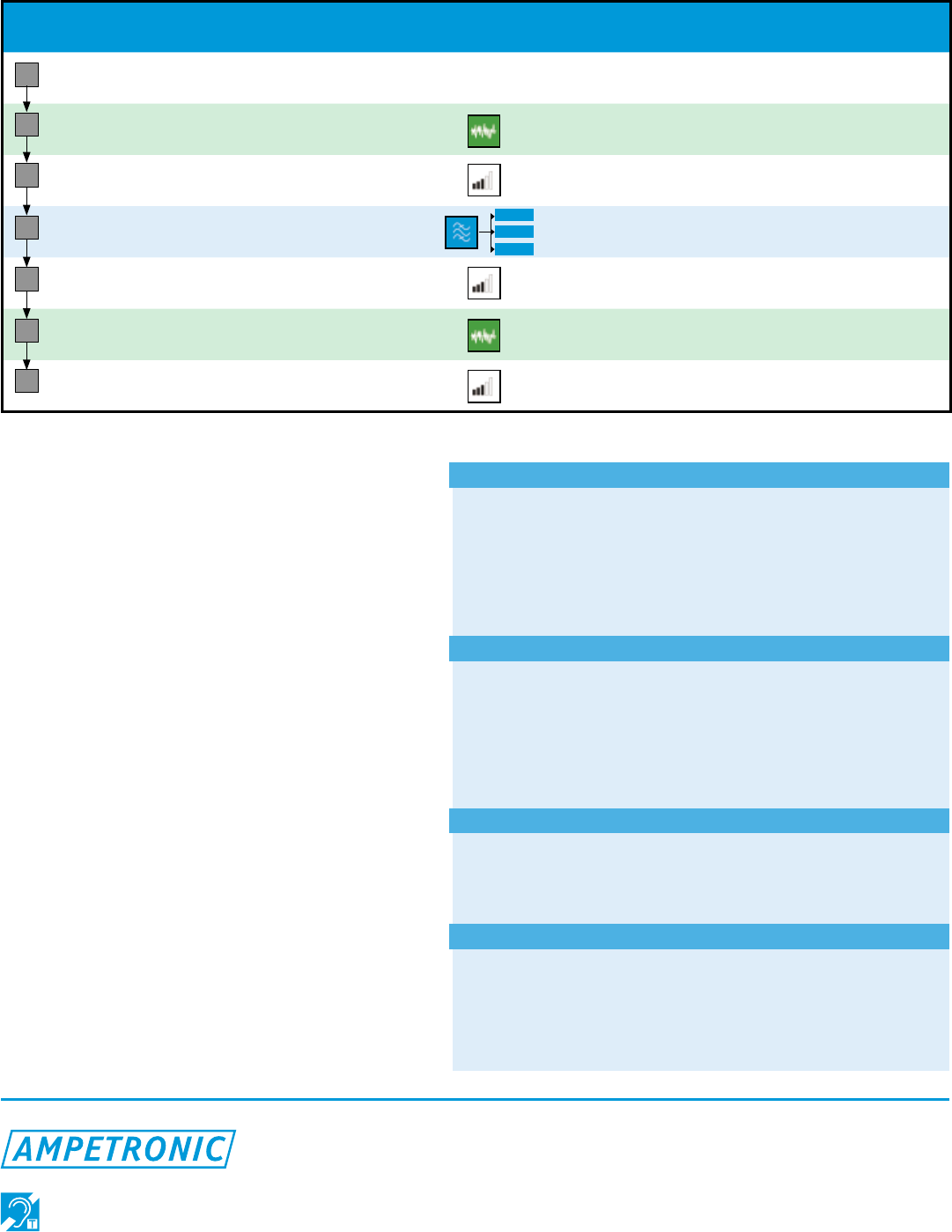
Step Audio Input FSM settings Adjustments Performance
requirements
Volume
of use
SYSTEM
OFF METER off n/a Determine volume of
use Sketch Layout
Background
Noise
SYSTEM
OFF
Sources of
magnetic noise
<22dB essential
<32dB acceptable
Field
Strength (1)
Track: 1
COMBINATION* Loop current -3 to +3dB peaks
Frequency
Response
Track: 2
PINK NOISE
MLC / tone
control
-3 to +3dB peaks
compared to 1kHz
Field
Strength (2)
Track: 1
COMBINATION* Loop current -3 to +3dB peaks
Overspill
(if required)
Track: 1
COMBINATION n/a <42dB
(OFF SCALE)
System use ACTUAL SIGNALS Input gain -9 to 0dB peaks
Subjective - >OK
1
2
3
4
5
6
7
* Other signals may be used with revised performance requirements: PINK NOISE -9 to -3dB, 1kHz SINE -3 to +3dB
Magneticeldmeasurement
Coilorientation:Vertical when unit held upright
Referencelevel:400mA/m (In Field strength mode)
Frequencyresponse
50Hz to 8kHz ±0.25dB
30Hz to 10kHz -3dB
Gainstability: Better than 0.5dB over all conditions
Outputs
Display:
Flying spot LED bar graph with wide viewing angle
Colour coded (green for -3dB to +3dB)
Audio(headphone):
16Ω min (32Ω per side)
3.5mm stereo jack connector
Power
Battery: 2 x AA alkaline LED (supplied)
Batterymonitor: Battery OK when LED illuminated
Batterylife:Up to 100hrs use, dependent on use pattern
Physical
Dimension: 84 x 27 x 140mm (meter only)
Weight: 150g excluding batteries
Operatingenvironment:
-10 to +45˚C
10 to 85% RH
5kHz
1kHz
100hz
The FSM allows a complete test of an induction loop system to be performed with a simple six or seven step procedure as
shown in the table below. Using the FSM with the CD of test signals (included), all aspects of an installation can be examined
and adjusted to meet the requirements. A Certificate of Conformity (template included) is provided to record test results from this
procedure, and to certify that the installation meets the requirements of IEC 60118-4:2006.
Commissioning Procedure
