8073809 Circuit Diagram DW20 00c4.dft Asko Dishwasher DW20.1, .2, .3, .4, .C
2012-10-25
: Pdf Asko Dishwasher Dw20.1, .2, .3, .4, .C Asko_Dishwasher_DW20.1, .2, .3, .4, .C Asko
Open the PDF directly: View PDF ![]() .
.
Page Count: 2
Rev ind Revision Appd Year Week
8765432
1FORMAT A3
5678
E
D
A
B
1
C
F
32
This document must not be copied without
our written pemission, and the contents
thereof must not be imparted to a third party
nor be used for any unauthorized purpose.
Contravention will be prosecuted.
Asko Cylinda AB
4
Dimensions, Type, etc.
Pos.
Material
Name of item
Qty
Dens.Kg/dm3
Part No. Material
ASKO CYLINDA
Description(ENG)
Gen.tolerance
Scale
Description(SE)
Replace
Gen.tol.Angle
Rev Ind
Designed by
Project
Week
Year
Iss by Dept
Released by
1:1
ML
UD 00 41
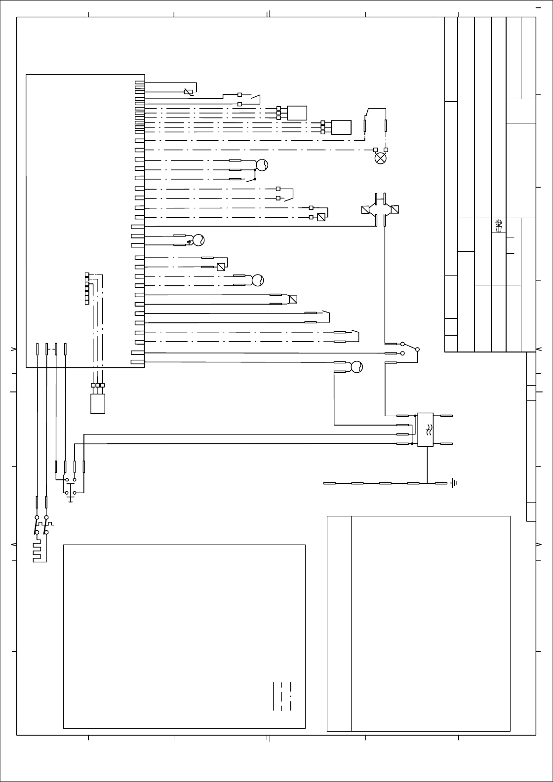
KOPPLINGSSCHEMA DW20.1, .2, .3, .4, .C
CIRCUIT DIAGRAM DW20.1, .2, .3, .4, .C
80 738 09 00
S:\U\Dw20\1_Tryckunderlag\Kopplingsschema\8073809 Circuit diagram DW20.4_c.dft , mall , 2002-06-18 08:34:08
E
D
A
B
C
F
DP
FN
F
DR
HE
CP
IV
VAX
MS
CD
RAS
DS
CP
DIV
SV
SS PS
1 2 3
TS
HS
IS
TH
MFM
L
N
WIRES IN ALL MACHINES
INTERNAL CONNECTION
WIRES IN SOME MACHINES
HL 1/C
2
NET
HE
123456 78
9
10
DP RAS DS CD FN VAX CP IV SV SS DIV HL TS PS FM TH
HS
HE
MS
1/C
3/4
2
FS
1/C
3/4
COMBI DISPENSER
CIRCULATION PUMP
WATER DIVERTER VALVE
DRAIN PUMP
DOOR
DOOR SWITCH
FILTER
FLOW METER
FAN
FLOAT SWITCH
HEATING ELEMENT
HALOGEN LAMP
HUMIDITY SENSOR
ILLUM. SWITCH
INLET VALVE
MAIN SWITCH
PRESSURE SENSOR
RINSE AID SENSOR
SALT SENSOR
SALT VALVE
THERMISTOR
TURBIDITY SENSOR
VAX ACTUATOR
INTERFACE TO HOME NET
COMMUNICATION UNIT
CD:
CP:
DIV:
DP:
DR:
DS:
F:
FM:
FN:
FS:
HE:
HL:
HS:
IS:
IV:
MS:
PS:
RAS:
SS:
SV:
TH:
TS:
VAX:
NET:
RESISTANCE
1 MOHM
12 OHM
30 OHM
25 KOHM
0.3 KOHM
1,3 OHM
22 OHM
90 OHM
56 OHM
25 OHM
150 OHM
85 OHM
2.6 KOHM
8,5 KOHM
0.95 KOHM
0.5 KOHM
0.95 KOHM
3,8 KOHM
2 KOHM
3,8 KOHM
<10 KOHM
1.1 KOHM
0.18 KOHM
0,75 KOHM
RESISTANCES AT ROOM TEMPERATURE (CA. 20°C/68°F)
VALUES WITH +/-10% ARE REGARDED AS NORMAL
COMPONENT
RADIO INTERFERENCE SUPPRESSION FILTER
HEATING ELEMENT 1400W 120V
HEATING ELEMENT 1800W 230V
THERMISTOR
COMBINED DISPENSER 120V
COMBINED DISPENSER 230V
CIRCULATION PUMP 120V 60HZ
CIRCULATION PUMP 230V 50HZ
CIRCULATION PUMP 220V 60HZ
DRAIN PUMP 120V 60HZ
DRAIN PUMP 230V 50HZ
DRAIN PUMP 230V 60HZ
SPRAY ARM DIVIDER 120V 60HZ
SPRAY ARM DIVIDER 230V 50/60HZ
INLET VALVE SINGLE INCL. FLOW SENSOR 120V
INLET VALVE SAFETY INCL. FLOW SENSOR 120V
INLET VALVE WATER SOFTNER INCL. FLOW SENSOR 120V
INLET VALVE SINGLE INCL. FLOW SENSOR 230V
INLET VALVE SAFETY INCL. FLOW SENSOR 230V
INLET VALVE WATER SOFTNER INCL. FLOW SENSOR 230V
HALOGEN LAMP 5W 12V
WAX MOTOR
FAN MOTOR 120V
FAN MOTOR 230V
Rev ind Revision Appd Year Week
8765432
1FORMAT A3
5678
E
D
A
B
1
C
F
32
This document must not be copied without
our written pemission, and the contents
thereof must not be imparted to a third party
nor be used for any unauthorized purpose.
Contravention will be prosecuted.
Asko Cylinda AB
4
Dimensions, Type, etc.
Pos.
Material
Name of item
Qty
Dens.Kg/dm3
Part No. Material
ASKO CYLINDA
Description(ENG)
Gen.tolerance
Scale
Description(SE)
Replace
Gen.tol.Angle
Rev Ind
Designed by
Project
Week
Year
Iss by Dept
Released by
1:1
ML
UD 00 41
KOPPLINGSSCHEMA DW20.1, .2, .3, .4, .C
CIRCUIT DIAGRAM DW20.1, .2, .3, .4, .C
80 738 09 00
S:\U\Dw20\1_Tryckunderlag\Kopplingsschema\8073809 Circuit diagram DW20.4_c.dft , mall , 2002-06-18 08:34:08
E
D
A
B
C
F
SERVICE MENU
TURN OFF MAIN SWITCH
WAIT FOR AT LEAST 5 SECS
*HOLD PROGRAM AND START BUTTONS (S1 & S2)
TURN ON MAIN SWITCH
RELEASE PROGRAM AND START BUTTONS (S1 & S2)
*FOR DW20.4 HOLD TEMPERATURE/SET AND
DRYING/MENU BUTTONS (S3 & S4)
VARIANT SETTING
*ACTIVATE THE SERVICE MENU
PRESS START (S2) 3 TIMES WITHIN 5 SECS
*FOR DW20.4
HOLD PROGRAM AND START BUTTONS (S1 & S2)
TURN ON MAIN SWITCH
RELEASE PROGRAM AND START BUTTONS
PRESS START (S2) 3 TIMES WITHIN 5 SECS
TOTAL RESET
TURN OFF MAIN SWITCH
WAIT FOR AT LEAST 5 SECS
HOLD PROGRAM BUTTON (S1)
TURN ON MAIN SWITCH
RELEASE PROGRAM BUTTON (S1)
Displays
COMPONENT TEST:
First enter Service menu.
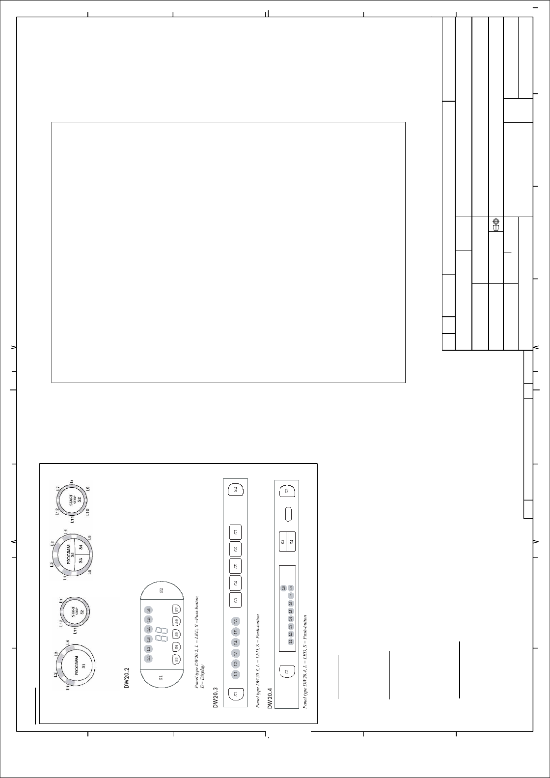
DW20.1
N
o component test avalible.
DW20.2 and DW20.3
Component test:
Press the Programme button (S1) and index through the following components:
1. Inlet valve
2. Salt valve (only machines with water softener)
3. Detergent and surfactant dispenser
4. Circulation pump
5. Heating element and circulation pump (Max 75°C)
6. Fan
7. Drain pump
DW20.4
First enter service menu.
Press Drying/Menu (S4) to access component diagnostics.
Press Temperature/Set (S3) to activate the following components:
1. Inlet valve (display shows water intake volume)
2. Salt valve (only machines with water softener)
3. Detergent and surfactant dispenser
4. Circulation pump (display shows turbidity in Volts)
5. Heating element and circulation pump (Max 75°C)
6. Fan (display shows humidity sensor value)
7. Drain pump (display shows pressure sensor reading; 0.5-3.5 VDC)
DW20.1
Panel type DW20.1, L = LED, S = Push-button
