BCBCAT
2015-05-08
: Pdf Bcbcat BCBCAT 04 2015 x7mag uploads wp-content
Open the PDF directly: View PDF ![]() .
.
Page Count: 77
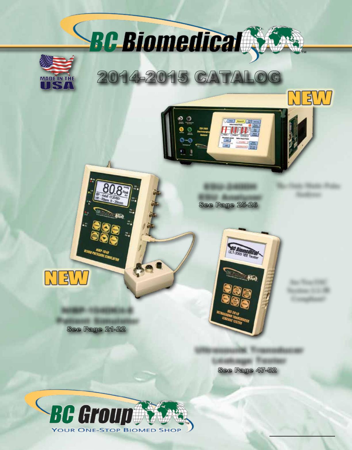
2014-2015 CATALOG
ESU-2400H
ESU Analyzer
ESU-2400H
ESU Analyzer
See Page 25-26
NIBP-1040Kit-E
Patient Simulator
NIBP-1040Kit-E
Patient Simulator
See Page 21-22
Ultrasound Transducer
Leakage Tester
Ultrasound Transducer
Leakage Tester
A UNIT OF BC GROUP INTERNATIONAL, INC.
Are You IAC
Section 2.2.3B
Compliant?
e Only Multi-Pulse
Analyzer
✔ Cardiac Output
✔ Fetal Maternal
✔ NIBP
✔ IBP
✔ ECG
✔ Arrhythmias
✔ Performance
✔ SPO2
✔ Temp
See Page 47-52
BC Group International, Inc.
3081 Elm Point Industrial Dr.
St. Charles, MO 63301 USA
1-314-638-3800 or 1-888-223-6763
1-314-638-3200 Fax
Shop Online at...
www.bcgroupintl.com
History
History of BC Biomedical
History
BC Group was founded in 1988. In 2000, we
began manufacturing our own product line under
the now familiar Green and Gold “BC Biomedical”
label.
In January of 2005, Lloyd Industries, the company
that engineered and manufactured most of the BC
Biomedical brand products, purchased BC Group.
This acquisition has allowed our products and
services to expand at an even faster pace. BC
Group, under the “BC Biomedical” brand, is now
the second largest manufacturer of Biomedical
Test and Measurement Equipment in the world.
Our philosophy with BC Biomedical products runs
counter to the current trend of “one-size-ts-all.”
We offer families of products that provide the users
with a choice of models so they can pick the
features they need at a price they can afford.
We just introduced our new ESU-2400H
Electrosurgery Analyzer with enhanced ability to
detect waveforms with a higher sampling rate.
(Upgrade path for previous models available.)
BC Group has a major commitment to Quality at all
levels of our operation. The company is certied to
ISO 9001:2008 and ISO 13485:2003.Our Service
Center is accredited to both ANSI Z540-1 and
ISO/IEC 17025:2005 with full traceability to NIST.
We are Registered with and Inspected by the FDA
and follow the Good Manufacturing Practices
(GMP) as well as comply with the QSR (Quality
Systems Regulation) 21CFR820.
Keep checking our website for the latest additions
to the BC Biomedical Line.
History of BC Biomedical
1-888-223-6763 - bcgroupintl.com
SF-SLS-180 (A) BC Biomedical Catalog
Table of Contents
Table of Contents
Any of the trademarks, service marks or similar rights that are
mentioned, used or cited within are the property of their respective
owners. Their use here does not imply endorsement or afliation
with any of the holders of any such rights.
Table of ConTenTs
safeTy analyzers 1-6
PaTienT simulaTors 7-14
DefibrillaTor analyzers 15-20
nibP simulaTors 21-24
esu analyzers 25-36
DigiTal Pressure meTers 37-42
Pulse oximeTry TesTing 43-44
infusion PumP analyzers 45-46
ulTrasounD leakage TesTer
47-52
ulTrasounD WaTT meTers 53-54
DeW PoinT meTer 55-56
anesTheTiC agenT analyzer 57-58
mulTi gas analyzer 59-60
benChToP floW analyzer 61-62
hanDhelD floW analyzer 63-64
Tsi CerTifier 63-64
lung simulaTors 67-68
TaChomeTer series 69-70

Safety Analyzer Series
Safety Analyzer Series
Safety Analyzer Series
Safety Analyzer Series
1-888-223-6763 - bcgroupintl.com
1
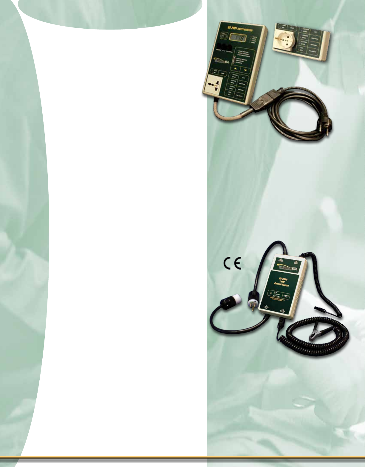
Features - SA-2000 Series
± Small & Lightweight Portable Analyzer
± Line Voltage Measurement
± Device Under Test Current Measurement
± Earth/Ground Lead Resistance/
Leakage Current
± Point-to-Point Testing
± Enclosure/Chassis Leakage Current
± External Resistance
± External Leakage Current
± Source Receptacle Wiring Integrity
Monitor
± MAP (Isolation) Function
± Internal ECG Simulator (SA-2010S Only)
± True RMS Readings
± AAMI ES1-1993 or IEC 601 Selectable
Test Loads
± 90 to 264 VAC Operation
± Touch Control Keys - No Knobs
± LED Status Indicators
± Audible Feedback
± Self-Test Points
± Externally Replaceable Ground Fuse
± Automatic Delay on Power Polarity
Reversal to DUT
± Soft-Sided Carrying Case
± International Versions Available
Optional
± External Point-to-Point (Red) Cable
± Kelvin Cable (For four wire resistance
testing)
± RS232 add “-R” to part number
SA-2010S
The SA-2000 Series is a Microprocessor
based Electrical Safety Analyzer Family.
There are 5 models that provide everything
from the most basic testing functions to
the most complete set of features of any
handheld unit on the market.
The compact size makes the SA-2000
Family easy to hold and operate. All models
operate from 90 to 264 Volts @ 50/60 Hz,
with Load Currents up to 20 Amps, so there
is no need to purchase 2 different analyzers
to cover your testing needs. The SA-2010S
is the smallest safety analyzer available with
a built-in ECG Patient simulator.
The SA-2000 Family of Safety Analyzers
allows the user to choose the model that
best ts the application. The combination of
the best features at the best price makes this
Family of products a natural choice.
All models come with a soft-sided case and
Chassis (Black) cable. An optional External
Point-to-Point (Red) cable or a Kelvin cable
is also available.
1
2
Flip for product pricing - Page A
Safety Analyzer Series
Safety Analyzer Series
sPeCifiCaTions 2
Models: SA-2000 SA-2001 SA-2005 SA-2010 SA-2010S
Voltage (Rating) 90 to 264 VAC 90 to 264 VAC 90 to 264 VAC 90 to 264 VAC 90 to 264 VAC
Current (Rating) 20 A 20 A 20 A 20 A 20 A
RS232 On “-R”
Measures:
Voltage (VAC) No 90 to 264
(± 3% R)
90 to 264
(± 3% R)
90 to 264
(± 3% R)
90 to 264
(± 3% R)
Current (A) No 0 to 19.99
(± 5% R)
0 to 19.99
(± 5% R)
0 to 19.99
(± 5% R)
0 to 19.99
(± 5% R)
Leakage Current
(μA)
0 to 1999
DC & 25 to 1 kHz
(± 1% R)
1 kHz to 100kHz
(± 2.5% R)
100 kHz to 1 MHz
(± 5% R)
0 to 1999
DC & 25 to 1 kHz
(± 1% R)
1 kHz to 100kHz
(± 2.5% R)
100 kHz to 1 MHz
(± 5% R)
0 to 1999
DC & 25 to 1 kHz
(± 1% R)
1 kHz to 100kHz
(± 2.5% R)
100 kHz to 1 MHz
(± 5% R)
0 to 1999
DC & 25 to 1 kHz
(± 1% R)
1 kHz to 100kHz
(± 2.5% R)
100 kHz to 1 MHz
(± 5% R)
0 to 1999
DC & 25 to 1 kHz
(± 1% R)
1 kHz to 100kHz
(± 2.5% R)
100 kHz to 1 MHz
(± 5% R)
Resistance (ohms)
0 to 1.99
(± 1% R)
2 to 19.99
(± 1% R)
10 mA
0 to 1.99
(± 1% R)
2 to 19.99
(± 1% R)
10 mA
0 to 1.99
(± 1% R)
2 to 19.99
(± 1% R)
10 mA
0 to 1.99
(± 1% R)
2 to 19.99
(± 1% R)
10 mA
0 to 1.99
(± 1% R)
2 to 19.99
(± 1% R)
10 mA
Patient Leads 0 0 5 10 10
MAP (Isolation) No No Yes Yes Yes
Built-in ECG
Simuator No No No No Yes
AAMI & IEC Loads AAMI Only Yes Yes Yes Yes
Point-to-Point No Yes Yes Yes Yes
Test Points No Yes Yes Yes Yes
Test Capability:
Open Ground Yes Yes Yes Yes Yes
Reverse Polarity Yes Yes Yes Yes Yes
Open Neutral Yes Yes Yes Yes Yes
Open Line Yes Yes Yes Yes Yes
Size 8.65 x 5.73 x
1.92 Inches
8.65 x 5.73 x
1.92 Inches
8.65 x 5.73 x
2.40 Inches
8.65 x 5.73 x
2.40 Inches
8.65 x 5.73 x
2.40 Inches
Weight ≤ 2.5 Lbs
(1.14kg)
≤ 3.0 Lbs
(1.36kg)
≤ 3.0 Lbs
(1.36kg)
≤ 3.0 Lbs
(1.36kg)
≤ 3.5 Lbs
(1.59kg)
Safety Analyzer Series
Safety Analyzer Series
Safety Analyzer Series
Safety Analyzer Series
Features - CS-2000 Series
± Two Models Available: CS-2000-U (US
Version; has US Plug & Socket) and CS-
2000-E (European Version; has
European “Schuko” Plug & Socket)
± Facilitates Testing to IEC 601
Requirements
± Interfaces Directly to BC Biomedical
SA-2000 & SA-2000-INTL Series of
Safety Analyzers
± Interfaces with Dale Technology®
LT544D, LT544D Lite, 601 & 601E Safety
Analyzers
± Universal Power Supply (90 to 264 VAC,
50/60 Hz)
± 1 Amp Current Source for Resistance
Measurements
± No Protruding Push Buttons
± Light Touch Key Used to Operate
± Small Size
CS-2000
The CS-2000 Series is a 1 Amp current
source for testing the ground continuity in
equipment. This device facilitates testing to
IEC 601 requirements, where a 1 Amp source
current is required. This device interfaces
directly with the BC Biomedical SA-2000
Series of Safety Analyzers as well as the
Dale Technology® LT544D, LT544D Lite &
601/601E. This Series comes in 2 models, US
and European plug & socket congurations.
Features - SA-2000-INTL Series
± Five Models Available: SA-2000-INTL,
SA-2001-INTL, SA-2005-INTL,
SA-2010-INTL & SA-2010S-INTL
± All of the Same Features Available as
the Domestic Counterpart
± Universal Power Receptacle Accepts
Almost Any International Power Plug
Conguration
± Detachable Power Cord Allows for use
in Any Country
± MultipleInternationalConguration
Power Cords Available
± AAMI ES1-1993 or IEC 601 Selectable
Test Loads
± 90 to 264 VAC Operation
± Soft-sided Carrying Case & Chassis
Cable Included
SA-2001-INTL
The SA-2000-INTL Series is ideal for inter-
national customers or for those that simply
need a power cord conguration that is dif-
ferent from the standard NEMA 5-15P con-
guration that is standard on our SA-2000
Series. Interchangeable power cords make
power input switching extremely easy and
the universal conguration power recep-
tacle is compatible with almost all countries
around the world.
3
3
Universal Power Receptacle
with BC20-20221 Installed for
Schuko use
1-888-223-6763 - bcgroupintl.com

Safety Analyzer Series
Safety Analyzer Series
BC20-20403
Schuko-
Continental
Europe
4
4
Cs-2000 sPeCifiCaTions
sa-2000-inTl series informaTion
Typical Power Cord Options Available for the SA-2000-INTL Series
BC20-20401
Japan
BC20-20410
Switzerland
BC20-20416
Australia
BC20-20402 United
Kingdom
BC20-20409 India/
South Africa BC20-20412 Italy
BC20-20400 North
America Hospital
Grade
Pick Your Country’s Connector
from Above
to Connect to the
SA-2000-INTL Series
Standard Product Plug
Standard Power Cord
BC20-20200 Use
with
SA-2010S INTL
BC20-20221 Schuko Plug
Ground Adapter
Electrical
CURRENT SOURCE 1.00 to 1.02 A DC
OPERATING LINE VOLTAGE 90-264 VAC, 50/60 Hz
POWER CONSUMPTION 12 VA (12 W)
LOAD CURRENT This device is an accessory to a Safety Analyzer, refer to applicable Safety Analyzer User
Manual for this Rating
LINE PLUG
CS-2000-U NEMA 5-15P
CS-2000-E European CEE 7/7 “Schuko”
DUT
RECEPTACLE
CS-2000-U Hospital Grade NEMA 5-15R
CS-2000-E European CEE 7/7 “Schuko”
CONNECTIONS
LINE PLUG 3 Pin Locking Plug for Safety Analyzer Chassis Cable Connection (See
Description section for Compatible Safety Analyzers)
Detachable Kelvin Cable (BC20-20114) for
DUT Ground Connection
Physical
SIZE 7.09 x 3.94 x 1.56 Inches
(180 x 100 x 40 mm)
ENCLOSURE ABS Plastic
Back-printed Lexan Overlay
WEIGHT < 1 Lbs (0.45 kg)
OPERATING RANGE 0 to 50 °C (32 to 122 °F)
10 to 90% RH, Non-Condensing
STORAGE RANGE -40 to 60 °C (-40 to 140 °F)
Flip for product pricing - Page B
Safety Analyzer Series
Safety Analyzer Series
Safety Analyzer Series
Safety Analyzer Series
1-888-223-6763 - bcgroupintl.com
5
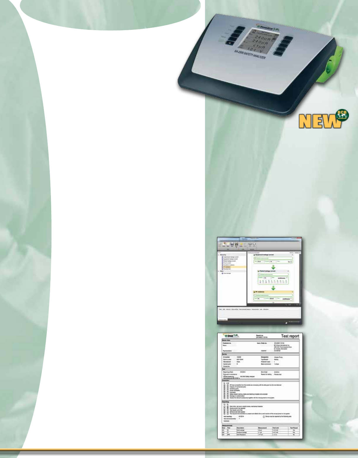
Features - SA-2500
± Full PC Automation with
Procedures and Reports
± Small & Lightweight Portable Analyzer
± Line Voltage Measurement
± Device Under Test Current Measurement
± Earth/Ground Lead Resistance/Leakage
Current
± Point-to-Point Testing
± Enclosure/Chassis Leakage Current
± External Resistance
± External Leakage Current
± Source Receptacle Wiring Integrity
Monitor
± MAP (Isolation) Function
± True RMS Readings
± 90 to 240 VAC Operation
± Touch Control Keys - No Knobs
± Audible Feedback
± Automatic Delay on Power Polarity
Reversal to DUT
± Soft-Sided Carrying Case
± International Versions Available
Optional
± BC20-20150 – Chassis Cable (Non-
Kelvin), optional for external
measurement mode
± BC20-20151 – Chassis Cable (Kelvin),
one comes with the unit
SA-2500
The SA-2500 is an Electrical Safety
Analyzer with Full PC Automation.
There are 2 Modes of operation, Manual
and Remote. The Manual mode allows
most basic testing functions to be stepped
through one at a time. With the Remote
mode, measurements are controlled via
a PC. The user has the possibility to inte-
grate all measuremetns into the individual
operator interface at the PC and to dene
test sequences.
5
PC Interface
(Included)
Sample
Report
(Included)

6
Flip for product pricing - Page B
Safety Analyzer Series
Safety Analyzer Series
sPeCifiCaTions
6
SA-2500
Electrical
Voltage (Rating) 90-240 VAC
Current (Rating) 16A
Remote Control USB
Measurements
Voltage (VAC) 90 - 240 (+/-5%)
Current (A) 0 to 16.00 (+/- 5%)
Leakage Current 10 to 300 uA(+/- 5%)300 uA to 30 mA (+/- 5%)
Resistance (Ohms) 0.01 to 30.00 (+/- 10%)
Patient Leads 10
MAP (Isolation) Yes
Built-In ECG Simulator No
Test Load IEC
Point to Point Yes
Test Points No
Test Capability
Open Ground Yes
Reverse Polarity Yes
Open Neutral Yes
Open Line Yes
Size 12.8 x 9.8 x 3.5 Inches
Weight < 4.4 Lbs (2 kg)
Measuring Leakage Current
Frequency response is taken into
consideration in accordance with
the diagram to the right when leak
age current is measured.

Multi-Parameter Simulators
Multi-Parameter Simulators
Patient Simulator Series
Patient Simulator Series
Features - PS-2200 Series
± Simple to Operate
± Independent Lead Outputs Produce a
True 12 Lead ECG Signal
± 1, 2 or 4 Invasive BP Channels
± All BP Waveforms Available on all BP
Channels
± 49 Arrhythmia Selections
± Respiration & Temperature Simulation
± ECG Performance Waveforms
± Dual Graphical Displays with Backlighting
± Drop Down Choice Screens List all
Options for Parameters
± Special Power Up Feature Allows User
to Choose to use Default, Last or Custom
Settings
± Auto Sequences for BPM,
Static-Pressure Levels & Performance
± 10 AHA & European Color Coded
Universal Patient Lead Connectors
(with Enough Space Between Posts for
the Large Diameter Connectors)
± Mini DIN Connectors Compatible with
Standard BP Cables (Optional
Mini DIN-M to DIN-F Cable Adapter)
± % Battery Life & Low Battery Indicator
± Powered by Two 9V Batteries or
Optional Battery Eliminator
± Full Remote Operation via RS232
± Flash Programmable, Field Upgradeable
± Battery Eliminator
Optional
± SpO2 Simulation
± Cardiac Output
± Fetal/Maternal Output
± Remote PSR-2200
PS-2240
The PS-2200 Multi-Parameter Patient
Simulator Series is the most comprehensive,
easy to use simulator on the market. These
new portable simulators are intuitive to use
since there are NO MORE CODES to enter.
Each model provides ECG, Blood Pressure,
Respiration and Temperature Simulation.
Models are available with one, two or four
independent blood pressure outputs. All
models will support the Fetal/Maternal, SpO2,
Cardiac Output and PSR-2200 Remote
options.
The PS-2200 Series makes viewing and
selecting the desired waveforms and param-
eters quick and intuitive. All operational infor-
mation is available at the same time on two
cursor-based graphic displays, allowing for
easy maneuvering through parameters and
scrolling through available options.
7
7
1-888-223-6763 - bcgroupintl.com

Patient Simulator Series
Patient Simulator Series
8
8
sPeCifiCaTions
PS-2210
with Cardiac
Output Option
PS-2220
To Compare Patient Simulators,
see chart on Page 14.
Flip for product pricing - Page D
PS-2200
ECG NSR
Rate
30,40,45,60,80,90,100,120,
140,160,180,200,220,240,2
60,280, 300 BPM
Accuracy ± 1%
Amplitude
.05,.10,.15,.20,.25,.30,.35,.4
0,.45,.50,1.0,1.5,2.0,2.5,3.0,
3.5,4.0,4.5,5.0 mV
Accuracy ± 2% @ Lead II
High Level 200 times Amplitude
Accuracy ± 5%
QRS Interval Adult (80ms), Pediatric (40ms)
ST Segment (Elevation) ± 0,.05,.1,.2,.3,.4,.5,.6,.7,.8 mV
ECG Performance
Sine Wave 0.1,0.5,5,10,40,50,60,100 Hz
Square Wave 0.125, 2.000 Hz
Triangle Wave 2.000, 2.500 Hz
Pulse Wave 30,60,120 BPM; 60 ms
Amplitude
.05,.10,.15,.20,.25,.30,.35,.4
0,.45,.50,1.0,1.5,2.0,2.5,3.0,
3.5,4.0,4.5,5.0 mV
R-Wave (Havertriangle)
Rate 30,60,80,120,200,250 BPM
Width
8,10,12,20,30,40,50,60,70,8
0,90,100,120,130,140,150,1
60,170180,190,200 ms
Amplitude
.05,.10,.15,.20,.25,.30,.35,.4
0,.45,.50,1.0,1.5,2.0,2.5,3.0,
3.5,4.0,4.5,5.0 mV
Rate Accuracy ± 1%
Amplitude Accuracy ± 2% @ Lead II
R-Wave </= 20 ms ± 5% @ Lead II
Blood Pressure
Channels
1 – PS-2210
2 – PS-2220
4 – PS-2240
Static Pressure
-10,-5,0,20,40,50,60,80,100,
150,160,200,240,250,300,320
400 mmHg
Accuracy ± (2% of Reading + 2 mmHg)
Impedance 300 Ohms
Accuracy ± 10%
Excitation Range 2 to 16 V RMS
Excitation Frequency DC to 5 KHz
Sensitivity 5 or 40 µV/V/mmHg
Respiration Artifact 0 to 16 mmHg
Remote(Option)
Fully compatible with PSR-2200
Pacemaker Waveforms
Amplitude 1,2,3,4,5,6,7,8,9,10 mV
Accuracy ± 10%
Width 0.1,0.5,1.0,1.5,2.0 ms
Accuracy ± 5%
Rate 75 BPM
Accuracy ±1%
Respiration
Rate Apnea,15,20,30,40,60,80,
100,120 BrPM
Accuracy ± 1%
Impedance delta 0.1,0.2,0.5,1.0,2.0,3.0 Ω
Accuracy ± 10%
Baseline 500,1000,1500,2000 Ω
Accuracy ± 5%
Lead LA or LL
Temperature
Temperature 0,24,30,37,40 °C (32.0,
75.2,86.0,98.6,104.0 °F)
Accuracy ± 0.1 °C
Type YSI Series 400 and 700
Fetal / Maternal
Fetal Heart Rate 60,90,120,140,150,210,240 BPM
Inter Uterine Pressure
Response Types
Uniform Deceleration
Early Deceleration
Late Deceleration
Uniform Acceleration
IUP Wave Bell Curve with 90 mmHg
Peak and 90 Sec Width
IUP Trigger Manual
Auto: 2,3,5 Minute
Cardiac Output
Injectate Volume 10 cc
Injectate Temperature 0 °C or 24 °C , ±2%
Calibration Coefficient 0.542 (0 °C Inj), 0.595 (24 °C Inj)
Blood Temperature 37 °C (98.6 °F), ±2%
Cardiac Output 2.5,5.0,10.0 l/min, ±5%
Simulations
Normal Flow
Faulty Injectate
Left-to-Right Shunt
Temperature Calibration
Pulse
Temperature Calibration
Pulse 1.5 °C Down for 1 sec, ±1%
Catheter Type Baxter Edwards, 93a-131-7f
SpO2Simulation (MSP-2100 & Finger SIMTM Req’d.)
Rate 30 to 300 BPM
SpO2Output 80, 90 & 97%

Patient Simulator Remote
Patient Simulator Remote
Patient Simulator Series
Patient Simulator Series
The PSR-2200 Programmable Patient
Simulator Remote Control with Trending
Capability brings an unprecedented level
of functionality and ease of use to patient
simulator remote control. How would you
like to have all of your patient simulators’
outputs available to you on a handheld, easy
to use remote control, up to 25-feet away
from your simulator? There’s nothing else on
the market that even comes close to the
PSR-2200.
You can easily access every output
waveform of your patient simulator with-
out ever touching it! Control outputs from
NSR, Arrhythmias, Resp, Temp, CO, ECG and
Resp artifact, ST Elevation Levels, Performance
Waves, etc. Use the included PC Software
utility to assign any outputs you like to any or
all of the 18 programmable keys. Congure
sequences (trends) to any of these keys
that will run from 1 to 600 seconds per step.
“Daisy-chain” the 18 programmable keys
to provide up to 30 hours worth of unique
trended patient data. Save a virtually unlim-
ited number of congurations. Set up one
remote and then “clone” the setup to as
many remotes as you want. You can e-mail
PSR-2200 conguration les. The PSR-2200 is
Flash upgradeable in the eld, ensuring that
your device will never become outdated.
Features - PSR-2200 Remote
± Large Easy to Read 128 x 64 pixel
Graphical LCD Display
± Small and Lightweight
± 10 Default Output Keys (adjustable)
± 18 Programmable Keys
± 25-foot Coiled Cord
± Easily Access Each and Every Output
Waveform, Rate and Level of Your
Patient Simulator
± Over 20 hours of Operation from a
Single 9V Battery
± Up to 30 hours of Trended Data Output
± Endless Looping Capability on Trended
Data
± 180 User-Programmable Steps for
Waveform Output
± VirtuallyUnlimitedUser-Congured
Waveform One-Touch Key Output
CongurationsthroughUseofthe
PSR-2200 PC Software Utility
± “Clone”aSpecicRemoteControl
Setup to Other Remotes
± Flash Programmable, Field Upgradeable
± Powerful yet Remarkably Easy to Use
Companion PC Software Setup Utility
± CanbeConguredtoWorkWith
Competitive (Non BC Biomedical
Brand) Patient Simulators
Optional
± USB to Serial Port Adapter
PSR-2200
9
9
1-888-223-6763 - bcgroupintl.com

Specications
Easy to read display shows
current simulator outputs. Run
programmed sequences & know
where you are in the sequence.
Even BP outputs can be displayed
with a push of one key.
Flip for product pricing - Page D
The PSR-2200 comes with a Microsoft® Windows
Based Application Program that allows the user to
quickly and easily develop and upload almost any
conguration.Complextestingandtrendingroutines
can easily be generated and saved.
The software is self-installing and designed to mimic
the simulator screens, so there is almost no learning
curve, just point and click. The software works with
bothRS232andUSBportsandwillautomaticallynd
the PSR-2200 and identify it. Single click uploading (writ-
ing to) and downloading (reading from) the PSR-2200
allowforfullcloningandletransfers.
Compatibility
Requires a PC running Microsoft® Windows 8, Windows 7,
Windows Vista, Windows XP Home Version, Windows XP
Professional, Windows 2000 (Service Pack 2 or higher),
Windows NT, Windows 98, with a USB Port (required optional
USB to Serial Adapter).
100% compatible with the BC Biomedical PS-2200 Family
of Patient Simulators (older simulators may require a Flash
rmware upgrade, which can be accomplished in the eld
with a special software update utility). The PSR-2200 can be
congured by special request to work with competitive brand
patient simulators from leading manufacturers.
Programming sofTWare
sCreen VieWs
Key
Number
Time until
next step
Sequence
Step
Assign names to each of the
18 programmable keys.
Select outputs from any simulator
waveform or output group.
Patient Simulator Series
Patient Simulator Series
Display LCD Graphical 128 x 64 Pixels
Enclosure 5.98 x 3.27 x 1.28 Inches, ABS Plastic
Weight < 1 Lbs
Faceplate Lexan, Back printed
Operating Range 15 to 40 °C
Storage Range -20 to 65 °C
Interface Cable 25’ Coiled Cord
Power One alkaline battery, 9V
(NEDA 1604 - battery life > 20 hours)
10
10
Patient Simulator Series
Patient Simulator Series
Patient Simulator Series
Patient Simulator Series
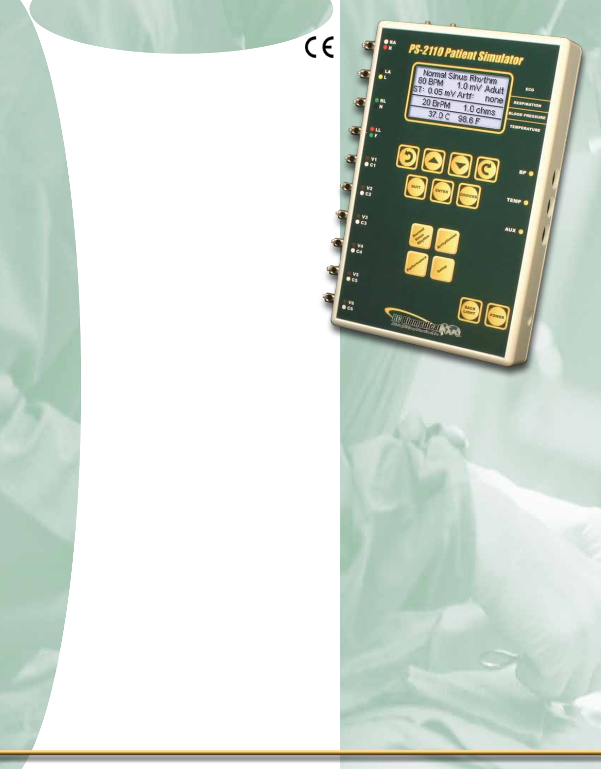
Features - PS-2100 Series
± Simple to Operate
± Independent Lead Outputs Produce a
True 12 Lead ECG Signal
± One Invasive BP Channel (PS-2110)
± Arrhythmia Selections
± Resp & Temp Simulation (PS-2110)
± ECG Performance Waveforms
± Graphical Display with Backlighting
± Drop Down Choice Screen List All
Options for Parameters
± Special Power Up Feature Allows the
User to Choose to use Default, Last or
Custom Settings
± Auto Sequences for BPM, Static-
Pressure Levels & Performance
± 10 AHA & European Color Coded
Universal Patient Lead Connectors
(with Enough Space Between Posts for
the Large Diameter Connectors)
± Mini DIN Connectors Compatible with
Standard BP Cables (Optional Mini
DIN-M to DIN-F Cable Adapter)
± % Battery Life Display & Low Battery
Indicator
± Powered by Two 9V Batteries or
Optional Battery Eliminator
± Full Remote Operation via RS232
± Flash Programmable, Field Upgradeable
± Battery Eliminator
Optional
± SpO2 Simulation
PS-2110
The PS-2100 Patient Simulator Series
offers cost effective simulation with many
features. If you only need ECG simulation,
the PS-2105 offers all of the features you
need. If you want basic Multi-Parameter
simulation, the PS-2110 is the right choice. It
provides ECG, Blood Pressure, Respiration
and Temperature Simulation, plus limited
Fetal/Maternal Simulation.
The PS-2100 Series makes viewing and
selecting the desired waveforms and param-
eters quick and intuitive, with all operational
information being available at the same time
on the cursor-based graphic display, allow-
ing for easy maneuvering through parame-
ters and scrolling through available options.
11
11
1-888-223-6763 - bcgroupintl.com

Patient Simulator Series
Patient Simulator Series
PS-2105
PS-2110 sPeCifiCaTions
12
12
ECG Functions
Rate 30,60,80,120,180,240,300 BPM
Accuracy ± 1%
Amplitude 0.5, 1.0, 1.5, 2.0 mV
Accuracy ± 2% @ Lead II
High Level 200 times Amplitude
ECG Performance
Sine Wave 0.1,0.5,5,10,40,50,60,100 Hz
Square Wave 0.125, 2.000 Hz
Triangle Wave 2.000 Hz
Rate Accuracy ± 1%
Amplitude Accuracy ± 2% @ Lead II
Blood Pressure
Static Pressure 0,20,40,80,100,200,250,300
mmHg
Accuracy ± (2% of Reading + 2 mmHg)
Impedance 300 Ω
Accuracy ± 10%
Excitation Range 2 to 16 V RMS
Excitation Frequency DC to 5 kHz
Sensitivity 5 or 40 µV/V/mmHg
Respiration
Rate Apnea,15,20,30,40,60,80,100,1
20 BrPM
Accuracy ± 1%
Impedance delta 0.1,0.2,0.5,1.0,2.0,3.0 Ω
Accuracy ± 10%
Baseline 500,1000 Ω
Accuracy ± 5%
Lead LA or LL
Temperature
Temperature 30,37,40 °C (86.0,98.6,104.0 °F)
Accuracy ± 0.1 °C ( ± 0.1 °F)
Type YSI Series 400 and 700
SpO2Simulation (MSP-2100 & Finger SIMTM Req’d.)
Rate 30 to 300 BPM
SpO2Output 80, 90 & 97%
PS-2110
Flip for product pricing - Page D
To Compare Patient Simulators,
see chart on Page 14
ECG Functions
Rate 30 to 300 BPM
Amplitude 0.05 to 5mV
S-T Segment Elevation ± 0.05 to 0.8 mV
Artifacts 50 Hz, 60 Hz, Muscle,
Baseline Wander, Respiration
QRS Interval Adult (80 ms) or Pediatric (40
ms)
Arrhythmia Functions
Arrhythmias 49 different
General Groups Supraventricular, Premature,
Ventricular, Conduction
Triggering Manual & Automatic
Pacemaker Functions
Waveforms
Atrial, Pacer, Asynchronous,
Non-Capture, Non-Function,
Demand - Occasional, De-
mand - Frequent, AV - Se-
quential
Pulse Height 1 to 10 mV
Pulse Width 0.1 to 2 ms
ECG-Performance Functions
Sine Waves 0.1 to 100 Hz
Square Waves 0.125, 2 Hz
Triangle Waves 5, 2.5 Hz
Pulse Waves 30, 60, 120 BPM; 60 ms Width
Amplitude 0.05 to 5 mV (Lead II)
Automatic Mode Yes
R Wave Rate 30, 60, 80, 120, 200, 250 BPM
R Wave Width 8 to 200 ms
R Wave Amplitude 0.05 to 5 mV (Lead II)
Training
Timer Manual, 10, 15, 20, 25, 30 s
Randomizer Off, On
Arrhythmias All, Subset
SpO2Simulation (MSP-2100 & Finger SIMTM Req’d.)
Rate 30 to 300 BPM
SpO2Output 80, 90 & 97%
PS-2105
PS-2105 sPeCifiCaTions
PS-2110
with (optional)
MSP-2100
& FingerSimTM

ECG Simulators
ECG Simulators
Patient Simulator Series
Patient Simulator Series
1-888-223-6763 - bcgroupintl.com
Overview - PS-2010
The PS-2010 is the perfect tool for pro-
viding a 10 lead wire hook up for those diag-
nostic 12 lead ECG machines. This small,
lightweight, feature packed simulator is a
must for your test equipment tool box.
± 10 AHA & European Color Coded
Leads
±Normal Sinus Rhythm &
Performance Waveforms
±
Universal Connectors
± Lead Test
Overview - PS-2006
The PS-2006 is unique in the market
place. Many of the new monitors now being
releasedhaveasixleadconguration.By
popular demand, the PS-2006, six lead ECG/
PVC simulator was developed. Press a but-
ton and insert PVCs into the ECG trace.
± 6 AHA & European Color Coded Leads
±Normal Sinus Rhythm &
Performance Waveforms
± Snap Connectors
± PVC Insertion
Overview - PS-2005
The PS-2005 is a small unit for those who
needveleadECGsimulationonlyandare
looking for a cost effective simulator. Need
to check your lead wires? There is a built
in lead wire tester for your convenience.
± 5 AHA & European Color Coded Leads
±Normal Sinus Rhythm &
Performance Waveforms
± Snap Connectors
± Lead Test
PS-2010
PS-2006
PS-2005
13
13
Patient Simulator Series
Patient Simulator Series
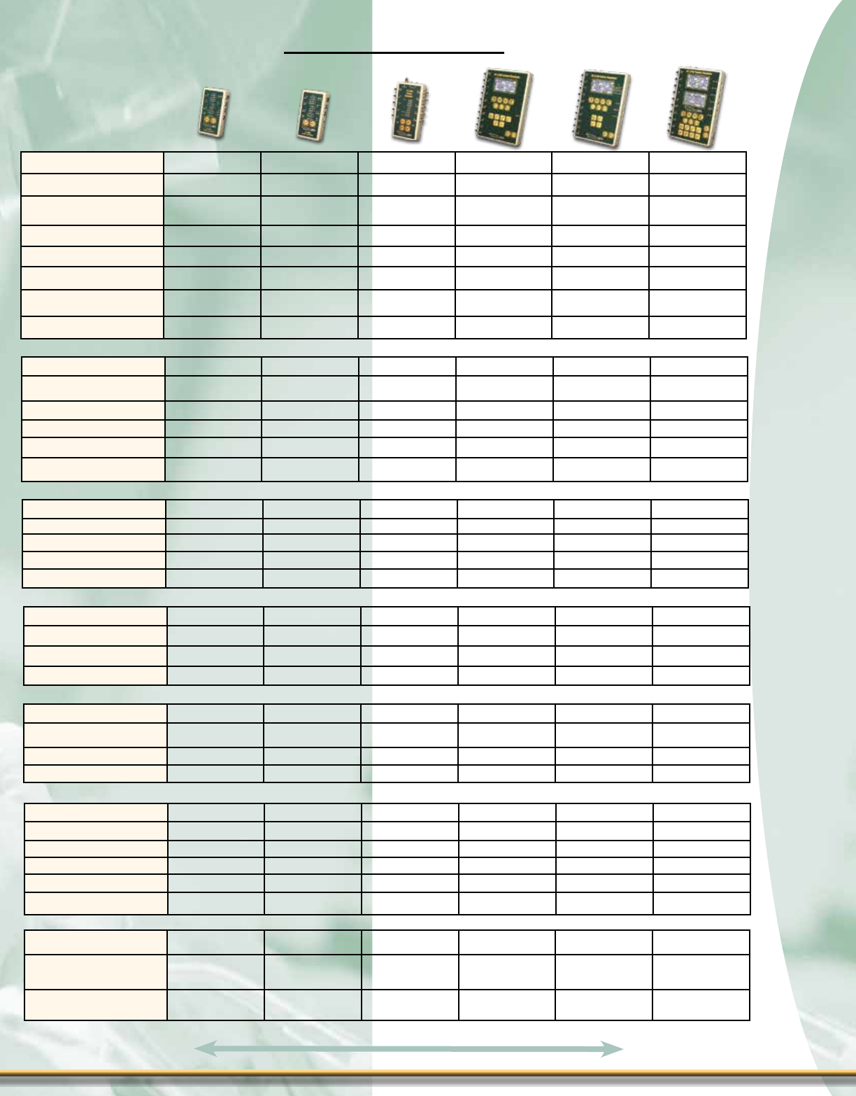
Models PS-2005 PS-2006 PS-2010 PS-2105 PS-2110 PS-2200
General
Display 11 LED 11 LED 11 LED 1 LCD Graphical
128x64 pixels
1 LCD Graphical
128x64 pixels
2 LCD Graphical
128x64 pixels
Backlight No No No Yes Yes Yes
Lead Test Terminals Yes No Yes No Yes Yes
RS232 No No No Yes Yes Yes
Power 1-9 Volt Battery 1-9 Volt Battery 1-9 Volt Battery 2-9 Volt Batteries 2-9 Volt Batteries 2-9 Volt Batteries
Battery Eliminator No No Yes Yes Yes Yes
ECG-NSR Yes Yes Yes Yes Yes Yes
Leads 5 6 10 10 10 10
Rates 4 4 4 17 7 17
Amplitudes 1114419
QRS Interval Adult Adult Adult Adult & Pediatric Adult Adult & Pediatric
ST Segment Elevation No No No 19 No 19
ECG-Performance Yes Yes Yes Yes Yes Yes
Sine Waves 333888
Square Waves 222222
Triangle Waves 111212
Pulse Waves -- -- -- 3 -- 3
Respiration No No No No Yes Yes
Rate -- -- -- -- 8 8
Baseline -- -- -- -- 2 4
Delta Impedance -- -- -- -- 6 6
Pacemaker No No No Yes No No
Arrhythmias No PVC on Demand No 49 12 49
Blood Pressure No No No No 1 Channel 1, 2, or 4 Channel
Temperature No No No No YSI 400/700 YSI 400/700
Special Modes
SpO2 Simulation No No No w/MSP-2100 w/MSP-2100 w/MSP-2100
Fetal/Maternal No No No No Yes Optional
Cardiac Output No No No No No Optional
Training Mode No No No Yes No Yes
Lead Test Yes No Yes No Yes Yes
Physical ABS Plastic Case ABS Plastic Case ABS Plastic Case ABS Plastic Case ABS Plastic Case ABS Plastic Case
Size 5.12” x 2.56” x
.97”
5.15” x 2.89” x
1.06”
7.26” x 4.46” x
1.51”
8.63” x 5.5” x
1.63”
8.63” x 5.5” x
1.63”
8.63” x 5.5” x
1.63”
Weight < 1 Lbs ≤ 0.5 Lbs
(0.23 kg) < 1 Lbs < 2 Lbs < 2 Lbs < 2 Lbs
14
14
Comparison Chart
Flip for product pricing - Page D
Defibrillator Analyzers
Defibrillator Analyzers
Defibrillator Analyzer
Defibrillator Analyzer
Features - DA-2006 Series
± Pulsed Biphasic, Biphasic and
Monophasic Compatible
± Fully AED Compatible
± Graphical Display with Backlighting
& Simultaneous Details of Parameters
with Scrolling Option Control
± On-ScreenViewingofDeb&Pace
Waveforms
± 5000 V, 1000 Joule Capacity
± High & Low Ranges
± Cardioversion Delay Measurement
± Charge Time Measurement
± Waveform Storage & Playback
± 10 AHA & European Color Coded
Universal Patient Lead Connectors
± 25 Pin Connector for Centronics Printer
± Power, two 9 V Batteries (Battery
Eliminator Furnished)
± Low Battery Indicator
± Flash Programmable, Field Upgradeable
± Auto Sequence Testing
± PC Utility Software for Auto Sequence
Development & Maintenance
± Storage for 50 Custom Sequences
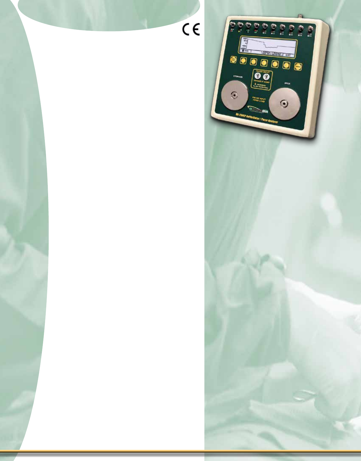
Features - DA-2006P
± 26 Selectable Internal Loads
± Full Pulse Analysis
± On-Screen Viewing of Pace Waveform
± Demand Sensitivity Test
± Refractory Period Tests
± 50/60 Hz Interference Test Signals
± PacerInputDebProtection
DA-2006P
The DA-2006 and DA-2006P Debrillator
Analyzer Series take advantage of the latest
electronic technology and deliver accurate,
consistent test results on all debrillators,
regardless of manufacturer or model.
Whether you need to test output energy,
cardioversion delay time, maximum energy
charge time, or test your AED, the DA-2006
and DA-2006P will deliver. You can even
capture and view the actual output ener-
gy and pacer waveforms to check for any
abnormalities.
With 26 internal test loads, the DA-2006P
delivers a full range of capabilities for test-
ing the Transcutaneous Pacemaker func-
tion of your advanced level debrillators,
including tests like demand sensitivity, refrac-
tory period, rate, pacer pulse width, pacer
pulse amplitude, etc. Test pacer function-
ality with the peace of mind that the Pacer
Input terminals on the DA-2006P are
internally protected against accidental de-
brillator discharge.
The DA-2006 & DA-2006P offers automated
testing. Create and store up to 50 unique
testing “auto sequences”, including both de-
brillator and pacer tests. You can easily edit
existing sequences and create new ones
with our unique PC-based utility software.
You can also “clone” a specic set of auto
sequences to multiple analyzers.
15
15
1-888-223-6763 - bcgroupintl.com

Defibrillator Analyzer
Defibrillator Analyzer
Our DA-2006-VL, works in conjunction with our DA-2006
Series Debrillator Analyzers, providing Variable Loads
used when testing Debrillators to assure the proper
electrical current is delivered to the heart, per IEC
60601-2-4 and AAMI DF80 standards. See page 19.
16
16
sPeCifiCaTions
Flip for product pricing - Page E
DA-2006_a
ENERGY OUTPUT MEASUREMENT
METHOD Monophasic, Biphasic or Pulsed Biphasic
LOAD RESISTANCE 50 Ω ± 1%, Non-Inductive (< 1 µH)
DISPLAY RESOLUTION 0.1 J
MEASUREMENT TIME WINDOW 100 ms
ABSOLUTE MAX PEAK VOLTAGE 6000 V
PULSE WIDTH 100 ms
CHARGE TIME MEASUREMENT 0.1 to 99.9 s
HIGH RANGE LOW RANGE
VOLTAGE ≤ 5000 V ≤ 1000 V
CURRENT ≤ 100 A ≤ 20 A
ENERGY ≤ 1000 J ≤ 50 J
ACCURACY ≤ 100 J ± 2 J ≤ 20 J ± 0.4 J
> 100 J ± 2% of reading > 20 J ± 2% of reading
TRIGGER LEVEL 100 V 20 V
PLAYBACK AMPLITUDE 1 mV / 1000 V Lead 1 1 mV / 1000 V Lead 1
TEST PULSE 125 J ± 20% 5 J ± 20%
OSCILLOSCOPE
OUTPUT ATTENUATION 1000:1 200:1
CARDIOVERSION
DELAY 0 to 6000 ms
RESOLUTION 0.1 ms
ACCURACY ± 2 ms
WAVEFORM PLAYBACK OUTPUT LEAD I & PLATES
SCREEN 200:1TimeBaseExpansion
SYNC TIME
MEASUREMENTS
TIMING WINDOW Starts at peak of each
R-wave
TEST WAVEFORMS All waveform
simulations available
DELAY TIME ACCURACY ± 1 ms
PATIENT SIMULATOR
ECG WAVEFORM
RATES
ECG NSR
30, 40, 45, 60, 80, 90, 100, 120,
140, 160, 180, 200, 220, 240,
260, 280, 300 BPM
SINE 0.1, 0.2, 0.5, 5, 10, 40, 50, 60,
100 Hz
SQUARE 0.125, 2.000 Hz
TRIANGLE 2.000, 2.500 Hz
PULSE WAVE 30, 60, 120 BPM; 60 ms
width
AMPLITUDE 0.5, 1.0, 1.5, 2.0 mV (Lead II)
ACCURACY RATE ± 1%
AMPLITUDE ± 2% @ Lead II
HIGH LEVEL OUTPUT 200 times Amplitude
ACCURACY ± 5%
QRS DURATION 80 ms
LEAD TO LEAD
IMPEDANCE 1000 Ω
ECG ARRHYTHMIA
SELECTIONS
Ventricular Fibrillation
Atrial Fibrillation
Second Degree A-V Block
Right Bundle Branch Block
Premature Atrial Contraction
PVC Early
PVC Standard
PVC R on T
Multifocal PVC
Bigeminy
Run of 5 PVCs
Ventricular Tachycardia
ECG SHOCK ADVISORY
ALGORITHM TEST
SELECTIONS
Asystole
Coarse Ventricular Fibrillation
Fine Ventricular Fibrillation
Multifocal Ventricular Tachycardia @ 140 BPM
Multifocal Ventricular Tachycardia @ 160 BPM
Polyfocal Ventricular Tachycardia @ 140 BPM
Polyfocal Ventricular Tachycardia @ 160 BPM
SupraVentricular Tachycardia @ 90 BPM
TRANSCUTANEOUS PACEMAKER ANALYZER
PULSE RATE RANGE 30 to 800 ppm
ACCURACY ± 1% or 2 ppm (whichever is greater)
PULSE WIDTH RANGE 0.6 to 80 ms
ACCURACY ± 1% or ± 0.3 ms (whichever is greater)
VOLTAGE VARIABLELOADINPUT 200 V
FIXED LOAD INPUT 15 V
OSCILLOSCOPE
OUTPUT
AMPLITUDE ATTEN-
UATION
0 – 15 V 10.24:1
15 – 60 V 41:1
> 60 V 164:1
MAX OUTPUT 200 V
DEMAND
SENSITIVITY
WAVEFORMS Square, Triangle, Haversine
WIDTH 10, 25, 40, 100, 200 ms
OUTPUT
AMPLITUDE
ECG OUTPUT 0 to 4 mV
PACER INPUT (50
TO 400 OHMS)
0 to 10
mV / 50 Ω
PACER INPUT (500
TO 2300 OHMS &
OPEN)
0 to 100 mV
DEFIBRILLATOR
PLATES 0 to 10 mV
OUTPUT
RESOLUTION
ECG OUTPUT 40 µV
PACER INPUT (50
TO 400 OHMS) 40 µV
PACER INPUT (500
TO 2300 OHMS &
OPEN)
1 mV
DEFIBRILLATOR
PLATES 0.1 mV
OUTPUT ACCURACY ± 2%
INPUT RATE
ECG OUTPUT N/A
PACER INPUT 30 to 100 ppm
DEFIBRILLATOR
PLATES 30 to 100 ppm
PACING 20 to 500 ms
REFRACTORY
PERIOD
SENSING 20 to 500 ms
ACCURACY ± 2 ms
50/60 HZ INTER
FERENCE TEST
SIGNAL
ECG OUTPUT 0,0.4,0.8, 1.2,1.6,2.0,2.4, 2.8,3.2,3.6,4.0mV
PACER INPUT
50 Ω 0,1,2,3,4,5,6,7,8,9,10mV
50 Ω 0,2,4,6,8,10,12,14,16,
18,20mV
150 Ω 0,3,6,9,12,15,18,21,
24,27,30mV
200 Ω 0,4,8,12,16,20,24,28,
32,36,40mV
300 Ω 0,6,12,18,24,30,36,
42,48,54,60mV
400 Ω 0,8,16,24,32,40,48,
56,64,72,80mV
≥ 500 Ω 0,10,20,30,40,50,60,
70,80,90,100mV
DEFIB PLATES 0, 1, 2, 3, 4, 5, 6, 7, 8, 9, 10 mV
TEST LOAD
LOAD VALUES
50, 100, 150, 200, 300, 400, 500, 600, 700, 800,
900, 1000, 1100, 1200, 1300, 1400, 1500, 1600,
1700, 1800, 1900, 2000, 2100, 2200, 2300 Ω
ACCURACY 50 to 1300 Ω ± 1%
1400 to 2300 Ω ± 1.5%
PULSE
CURRENT
RANGE 4 to 300 mA (100 Ω load)
ACCURACY ±5% or ± 0.5 mA(whichever is greater)
LIMIT
50 – 600 Ω 300 mA
700 Ω 286 mA
800 Ω 250 mA
900 Ω 222 mA
1000 Ω 200 mA
1100 Ω 182 mA
1200 Ω 167 mA
1300 Ω 154 mA
1400 Ω 143mA
1500 Ω 133 mA
1600 Ω 125 mA
1700 Ω 118 mA
1800 Ω 111 mA
1900 Ω 105 mA
2000 Ω 100 mA
2100 Ω 95 mA
2200 Ω 91 mA
2300 Ω 87 mA
DA-2006-VL

Defibrillator Analyzers
Defibrillator Analyzers
Defibrillator Analyzer
Defibrillator Analyzer
17
17
The BC Biomedical DA-2006 and DA-2006P debrillator analyzers take autosequence
test development to new levels. Never before has it been so easy to create new auto-
mated testing sequences, or edit existing ones. Our unique PC-based autosequence
development software allows you to build and edit these automated testing sequences on
your PC under the power and utility of the Windows operating system, rather than having
to work on a cryptic small instrument display like other analyzers. You can create up to
50 autosequences to download to your DA-2006 or DA-2006P.
A starter set of 19 autosequences is provided. Autosequences can be debrillator-only,
transcutaneous pacer-only, or a combination of both. Each autosequence can support
up to 20 output energy test steps, a maximum energy test (including charging time), a
cardioversion test (at up to three different power levels), and transcutaneous pacer tests.
You can take an existing autosequence and copy it to a new one, rename it, and make
any minor changes necessary to have a brand new sequence for a different make and
model debrillator.
You can “clone” multiple DA-2006 or DA-2006P analyzers by downloading the same
autosequence le to multiple analyzers. You can e-mail autosequence le sets for use in
eld or district ofces away from the main ofce when changes are made. You can even
save your DA-2006 or DA-2006P autosequence setup and easily put it back exactly the
same way it was, prior to repair and calibration of your instrument.
Programmable Autosequence
± PC Based Software
± Create up to 50 Autosequence
± Up to 20 Steps Per Autosequence
± Autosequences can be cloned
to Multiple Units
± Easily Share Autosequence Files
via Email
DA-2006
1-888-223-6763 - bcgroupintl.com

Defibrillator Analyzer
Defibrillator Analyzer
18
18
File Control
This section is utilized to load/save
conguration les on the PC as
wellasread/writetheautocongu-
ration in the DA-2006/P
ECG Sequence
Programming
Use this section to easily
congure each step of the
ECG Auto Sequence
Program Menu Bar
Sequence Selection
Use this list to select
which sequence to
view /edit.
Status Message
Com Port
being used
SequenceConguration
Use this section to congure
each Auto Sequence test.
Task
Progress
Indicator
Today’s
Date
Current Time
Programming auTo sequenCes oVerVieW
Compatibility
Requires a PC running Microsoft® Windows 8, Windows 7,
Windows Vista, Windows XP Home Version, Windows XP
Professional, Windows 2000 (Service Pack 2 or higher),
Windows NT, Windows 98, with a USB Port (required optional
USB to Serial Adapter).
Flip for product pricing - Page E
BC Group makes debrillator autosequence
development and editing easier than competi-
tive analyzers that offer such capability. Why
struggle with limited on-instrument displays
and cryptic development tools? Our DA-2006
and DA-2006P autosequence capability is in a
class of its own.

Defibrillator Analyzers
Defibrillator Analyzers
Defibrillator Analyzer
Defibrillator Analyzer
Features - DA-2006-VL
± Pulsed Biphasic, Biphasic and
Monophasic Compatible
± Fully AED Compatible
± 5000 V, 1000 Joule Capacity
± Smart Loads, no Settings to Change in
DA-2006 or DA-2006P
± 25-200 ohm Loads, 25 ohm Steps
DA-2006-VL
Our DA-2006-VL, works in conjunction with
our DA-2006 Series Debrillator Analyzers,
providing Variable Loads used when testing
Debrillators to assure the proper electri-
cal current is delivered to the heart, per IEC
60601-2-4 and AAMI DF80 standards.
Automatic detection of loads, no settings
to change or congure in the DA-2006/P.
Ensure that the correct load is selected in the
Debrillator output pulse measurement.
19
19
1-888-223-6763 - bcgroupintl.com

Defibrillator Analyzer
Defibrillator Analyzer
20
20
Flip for product pricing - Page E
Areyoutestingyourdebrillatorwiththerightloads?
The DA-2006 series and DA-2006-VL are the right answer for you. Not all
patients are the same, use the DA-2006-VL to test your debrillator with
test loads from 25 to 200 ohms, as required by IEC 60601-2-24 and AAMI
DF80 standards.
Do you need to measure Pulsed Biphasic waveforms?
If you already have a DA-2006, there is no need to purchase a new ana-
lyzer in order to measure pulsed biphasic waveforms. Simply update the
software in your DA-2006/P and you will be ready for testing.
Typical DA-CS-06 Setup
DebrillatorAnalyzerCalibration
System
Need to calibrate any
Debrillator?
NIBP Simulators
NIBP Simulators
NIBP Simulator Series
NIBP Simulator Series
Features - NIBP-1040-BE
± NIBP, IBP, ECG, Temp, Arrhythmias,
Respiration, Leak Detect & Much More
± Small, Hand-Held, Lightweight
± Cardiac Output
± Fetal Maternal
± Simple One Key Operation
± ± 500 mmHg Manometer
± Digital Pressure Envelope Offset
± Total Pressure & BP Waveform Displays
± Adult, Neonatal, Hypertensive &
Hypotensive Modes
± SpO2 Ready–Compatible with MSP-2100
Module & FingerSimsTM
± Multiple Display Screens & Digit Sizes
± Flash Programmable, Field Upgradeable
± Peak Pressure Detection with Easy Reset
± ECG Output with Full NSR Waveform
± Sinusoidal Respiration Simulation
± ECG Performance Test Waveforms
± Pace Waveform
± ECG Alarm Test
± Synchronized Invasive Blood
Pressure Output
± SelectableIBPSensitivity-5or40μV/V/
mmHg
± Leak Rate Test
± ECG Arrhythmia Waveforms
± ECG Arrhythmia Sequence
± YSI 400 & 700 Simulation Temperature
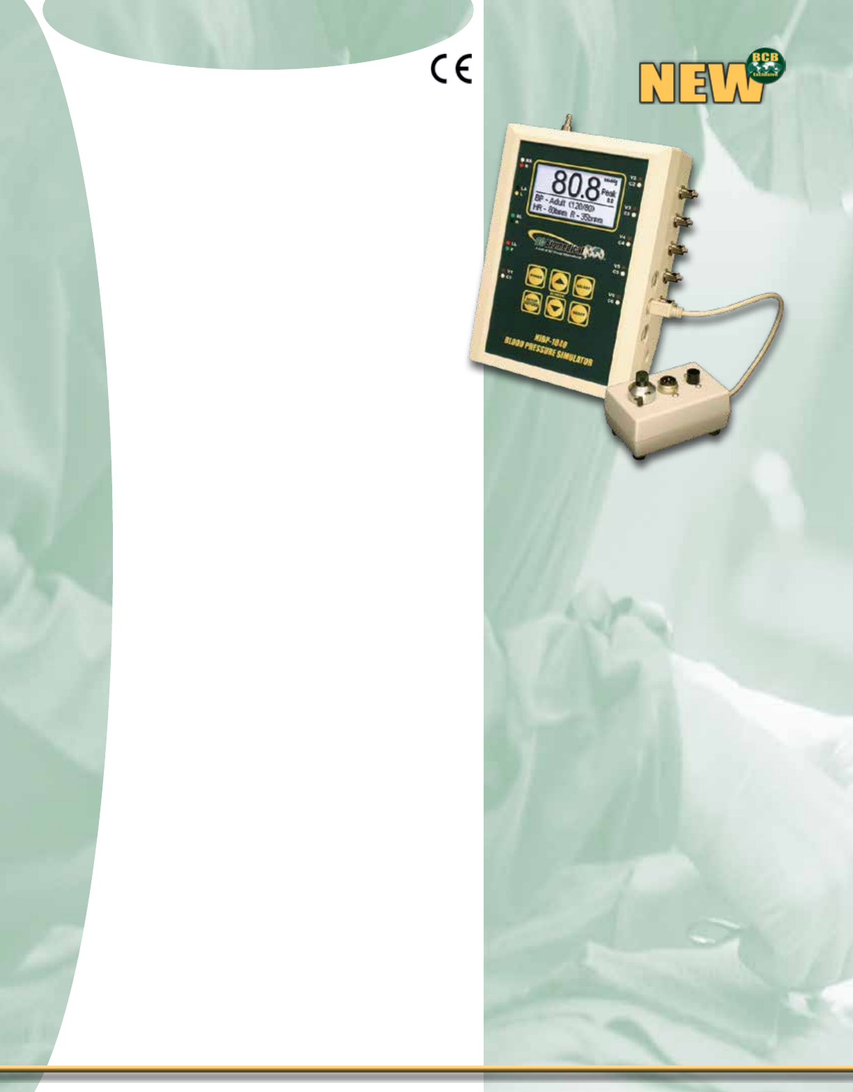
NIBP-1040-BE
The NIBP-1040-BE is the newest member
of the NIBP-1000 family of high quality, low
cost, high function microprocessor-based
NIBP simulators. The NIBP-1040-BE comes
with the Cardiac Output and Fetal Maternal
feature built-in. It is designed to meet the
demand for a small, easy to use unit with
multiple features to t your exact needs.
Though small, this complete Multiparameter
Simulator makes no compromise on provid-
ing true outputs.There is no other NIBP
Simulator on the market that offers all the
features of the NIBP-1040-BE in this price
range. The ability to provide offsets for
various manufacturers NIBP’S can only be
found in units costing twice as much.
The graphic display not only allows you to
see what is going on digitally, it also allows
you to view a plot of the overall pressure or
a close-up of the BP waveform.
The Flash Memory allows for eld upgrades
with downloads from our website.
21
21
1-888-223-6763 - bcgroupintl.com
Shown with
NIBP-1040-BE
Cardiac Output

Blood Pressure
Pressure Range: ± 500 mmHg @ 20 °C
Accuracy: ± (1% of Reading + 0.5 mmHg)
Simulation Rate: 80, 94 BPM (synchronized to ECG)
Accuracy: ±1%
Invasive Blood Pressure
Static Pressure: -10, -5, 0, 20, 40, 50, 60, 80, 100,
120, 150, 160, 200, 240, 250, 300,
320, 400 mmHg
Accuracy: ± (1% Full Range + 1 mmHg) or
± (2% Setting + 2 mmHg)
Impedance: 300 Ω (± 10% Accuracy)
Excitation Range: 2 to 16 Vrms
Excitation
Frequency: DC to 5 kHz
Sensitivity: 5 or 40 μV/V/mmHg
ECG NSR
Rate: 30, 60, 120, 240 BPM
(± 1% Accuracy)
Amplitude: 2.75 mV (± 2% @ Lead II
Accuracy)
ECG Performance
Sine Wave: 10, 60, 100 Hz
Square Wave: 0.125, 2.000 Hz
Triangle Wave: 2.000 Hz
Rate Accuracy: ± 1%
Amplitude: 2.75 mV (± 2% @ Lead II
Accuracy)
Pacemaker Waveforms
Amplitude: 3 mV (± 10% Accuracy)
Width: 6 ms (± 5% Accuracy)
Respiration
Rate Accuracy: ± 1%
Impedance: Delta 3.0 Ω (± 10% Accuracy)
Baseline: 1000 Ω (± 5% Accuracy)
Temperature
Settings: 0, 24, 30, 37, 40 °C (± 0.1 °C Accuracy)
(32.0, 75.2, 86.0, 98.6, 104.0 °F)
Type: YSI Series 400 and 700
Fetal/Maternal
Fetal heart rate: 60, 90, 120, 140, 150, 210, 240 BPM
IUP Period: Single Contraction (Manual) 2, 3, 5, Min
(AUTO)
FHR
(During Contraction): Uniform Deceleration
Early Deceleration
Late Deceleration
Uniform Acceleration
Cardiac Output
Injectate
Temperature: 0, 24 °C
Injectate Flow: 2.5, 5.0, 10.0 L/MIN
Other Outputs: Faulty – Injectate
Left-to-Right Shunt
Calibrated Temperature Pulse
Main Test Modes:
sPeCifiCaTionsScreen Views
Main Display
Output Waveform Screen
(NOTE: The output Waveform is NOT
Physiologically Correct)
Pressure Graph Screen
Adult 120/80
Adult 120/80 w/Pace
Adult High 190/120
Adult Low 80/40
Neonatal 70/40
Alarm Test
Arrhythmia Sequence
Leak Test
Manometer
Cardiac Output
Fetal Maternal
NIBP Simulator Series
NIBP Simulator Series
moDel summary
NIBP-1040Kit-E - Includes MCO-2100, built-in
rechargeable battery and Universal
Patient Lead Connectors
22
22
Flip for product pricing - Page H
Peak Detect
ECG Performance Waves
Individual Arrhythmias
Synchronized Dynamic
IBP
Static IBP
RS232
Other Modes/Features:
FETAL/MATERNAL
CARDIAC OUTPUT

NIBP Simulators
NIBP Simulators
NIBP Simulator Series
NIBP Simulator Series
23
23
1-888-223-6763 - bcgroupintl.com
Overview - NIBP-1030-BE
The NIBP-1000 Series is a Family
of high quality, low cost, high function
Microprocessor based NIBP Simulators.
They are designed to meet the demand for
a small, easy to use unit with multiple fea-
turestityourexactneeds.
You have the option of operating by
power cord or you can add the optional
internal rechargeable NiMH Battery. You
can perform hundreds of test on a fully
charged battery.
Though small, this Family makes no
compromise on providing true outputs. The
optional ECG waveforms are full QRS and
the respiration waveforms look real.
The graphic display not only allows you
to see what is going on digitally, it also
allows you to view a plot of the overall pres-
sure or a close-up of the BP waveform.
All models have the ability to adjust
the output depending on the manufactures
algorithm. (operators choice)
The Flash Memory allows for eld
upgrades with downloads from our website.
NIBP-1030-BE NIBP, Peak Detect,
Full Range Manometer, IBP, ECG, Pace,
Temperature, Arrhythmias, Respiration,
Leak Detect and Performance waveforms.
(Extended ECG post optional)
NIBP-1020 NIBP, Peak Detect, Full
Range Manometer, ECG, Pace Respiration
and Performance waveforms.
NIBP-1010 NIBP, Peak Detect and Full
Range Manometer
NIBP-1030-BE
NIBP-1010
NIBP-1020

NIBP Simulator Series
NIBP Simulator Series
AVAILABLE MODELS:
NIBP-1010 Basic unit
NIBP-1010-P + Peak
NIBP-1010-BP + Battery & peak
NIBP-1010-KIT NIBP-1010-BP, 5 adapters & soft carrying case
NIBP-1020 Basic unit with ECG
NIBP-1020-PA + Peak & alarm
NIBP-1020-BPA + Battery, peak & alarm
NIBP-1020-KIT NIBP-1020-BPA, 5 adapters & soft carrying case
NIBP-1030 Base unit
NIBP-1030-B + built-in rechargeable battery
NIBP-1030-BE + Universal Patient Lead Connectors
NIBP-1030Kit NIBP-1030-B, soft carrying case and 5 adapters
NIBP-1030Kit-E Same as above with Universal Patient Lead
Connectors
NIBP-1040Kit-E NIBP-1040-BE with Cardiac Output & Fetal
Maternal, Universal Patient Lead Connectors
soft carrying case and 5 adapters
moDel summary
sPeCifiCaTions
Flip for product pricing - Page I
Screen Views
Main Display
Composite Pressure Display
Output Pressure Display
(NOTE: The output Waveform is NOT
Physiologically Correct.)
NIBP-1010 with (optional)
MSP-2100 & FingerSimTM
Blood Pressure
Pressure Range: ± 500 mmHg @ 20 °C
Accuracy: ± (1% of Reading + 0.5 mmHg)
Simulation Rate: 80, 94 BPM (synchronized to ECG)
Accuracy: ±1%
ECG NSR
Rate: 30, 60, 120, 240 BPM; ± 1%
Amplitude: 2.75 mV; ± 2% @ Lead II
ECG Performance
Sine Wave: 10, 60, 100 Hz; ± 1%
Square Wave: 0.125, 2.000 Hz; ± 1%
Triangle Wave: 2.000 Hz; ± 1%
Pacemaker Waveforms
Amplitude: 3 mV; (± 10% Accuracy)
Width: 6 ms; (± 5% Accuracy)
Respiration
Impedance: Delta 3.0 Ω (± 10% Accuracy)
Baseline: 1000 Ω (± 5% Accuracy)
24
24

Features - ESU-2400H
± The Industry’s Most Comprehensive and
Most Accurate Full-Featured Analyzer
± Measure Advanced Generator Outputs with
Pulsed RF at Up to 3 Different Amplitudes
± Up to 16 million samples
± 1% Measurement Accuracy
± Based Upon Years of Collaborative Work
with Leading Electrosurgery Industry
Manufacturers
± Industry Standard RF Current Measurement
± DFATM Technology Ultra High Speed Digitization
of The Complex RF Waveform
± Compatible with The Latest ESU Generator
Platforms by The Major ESU Manufacturers
± Continuous & Pulsed Output Waveform
Compatible
± Embedded Real-Time Operating System with
¼ VGA Color Touch Screen Display
± Displays Up to 15 Different Measurement
Parameters with User Selectable and
DenableScreens
± InternalPrecisionTestLoadsFrom0Ωto
6400Ωin1ΩIncrements
± External Test Load Compatibility
± Automated Power Load Curves with Multiple
Power Settings Per Load Setting
± AutomatedUser-DenableTesting
Sequences
± Print test Reports to PDF format or USB Printer
± USB (3), RS232, and Ethernet Communications
Ports
± External Keyboard and Mouse Compatible
Via Dedicated Ports
± Automatic or Manual Activation of ESU
Generator During Power Load Curve Tests
± Remote Communications Capability with
ESU Generators
± 100% Compatible with Covidien/Valleylab
Force Triad & Ligasure Generators, Conmed
System 5000 Generators, and All Legacy
Generators by Other Manufacturers
± REM/ARM/CQMTestingVia500ΩAdjustable
Loadin1ΩIncrements
± RF Leakage Current Measurement
± Capture, Store, Print RF Waveform
ESU Analyzer Series
ESU Analyzer Series
ESU Analyzer Series
ESU-2400H
ESU Analyzer Series
25
1-888-223-6763 - bcgroupintl.com
The ESU-2400H offers an unprecedented buffer
depth of over 16 million samples. This allows for
ultra-stable measurements of ESU Generator
output waveforms and provides future-proong
for new generator outputs modes such as mul-
tiple pulsed waveforms.
The ESU-2400H uses the same base platform
as the ESU-2400. This means that you can
upgrade your existing analyzer without having to
purchase a whole new unit. You have the free-
dom to get started with the ESU-2400 and then
upgrade as the need arises.
The low impedance internal load bank has a
range of 0 to 6400 ohms in 1 ohm increments. It
is microprocessor based and utilizes a combina-
tion of unique hardware and software to provide
accurate and reliable test results, even from
“noisy” Electrosurgical Generator waveforms
such as “Spray”. The DFATM Technology uti-
lized in the ESU-2400H allows the system to
aggressively digitize the complex RF waveforms
produced by Electrosurgical Generators. Each
data point is analyzed to provide highly accurate
measurement results.
The ESU-2400H,unlike most convention-
al ESU Analyzers, has internal high voltage
setup relays to control the measurement path.
This allows the user to switch between Power
measurements,Leakage measurements, REM/
ARM/CQM testing, or even run an autosequence
that could include any or all of these tests – with-
out evenmoving wires around.
The current transformer internal to the ESU-
2400H senses the RF current owing through the
internal test load and produces a ratiometric
voltage, which is digitized and analyzed by the
microprocessor. Combining the standard and low
ranges of the ESU-2400H with the use of the cur-
rent transformer, the user has full control over the
ability to get high accuracy and high resolution
readings from all types of Electrosurgical
Generators
25

ESU-2400
page26
MEASUREMENTS
A/D Resolution 14 Bits
A/D Speed 64 MSPS
Bandwidth 50 kHz – 10 MHz
Measurement Accuracy ± 1% Reading
Current Range 2.0 to 700.0 mA RMS (Low Range)
20 to 7000 mA RMS (High Range)
Current Resolution 0.1 mA RMS (Low Range)
1 mA RMS (High Range)
Power Range (Watts) 500 Watts
Power Resolution (Watts) 0.1 Watt
Crest Factor Range 1.4 to 500
Crest Factor Resolution 0.1
Input Voltage Range
0.20 to 70.00 mV RMS (Low
Range)
2.0 to 700.0 mV RMS (High Range)
Voltage Resolution 0.01 mV (Low Range)
0.1 mV (High Range)
mV Peak/Peak-to-Peak Range 0.0 to 1.0
mV Peak/Peak-to-Peak Resolution 0.1
Load Bank Specifications
Internal Setup/Load Selection
Relays 10kV, 5A rated Reed Relays
Internal Load Selection
Internal Load Range 0 to 6400 Ω
Internal Load Accuracy ± 1% Non-inductive
Internal Load Power Ratings
1 Ω: 25 W
2 Ω: 50 W
4 Ω: 100 W
Remaining Loads: 225 W
Load Bank Duty Cycle 10 seconds on, 30 seconds off
Load Cooling Dual 120mm Variable Speed DC
Fans
External Load Selection
External Load Range 0 to 6400 Ω
External Load Resolution 1 Ω
SCREEN SIZE 5.7" QVGA 18 bit color touch
screen
SETUP MEMORY EEPROM, All Parameters
MEMORY RETENTION 10 Years w/o Power
OPERATING RANGE 15 to 30 °C (59 to 86 °F)
STORAGE RANGE -20 to 60 °C (-4 to 140 °F)
CONSTRUCTION Enclosure – Aluminum
Face – Lexan, Back Printed
SIZE 7.8 x 15.0 x 22.5 inches
198.1 x 381 x 571.5 mm
WEIGHT 31 lbs. (14 kg)
CONNECTIONS
Input: I/O 4mm Safety Jacks
3xUSB, 1xSerial, 1xEthernet
1xPS/2 Keyboard/Mouse
Output: 1xBNC Scope
Hypertronics 25-pin Footswitch
connector
POWER SUPPLY ADAPTER
Input: Universal 100-240 VAC, 50-
60 Hz
Output: 12 VDC
(Specify power cord see page Z)
ESU Analyzer Series
ESU Analyzer Series
Flip for product pricing - Page G
sPeCifiCaTions
esu-2400h
Pulse Mode 2
Pulse Mode
PulseModeCong
Pulse Mode 3
Advanced Pulsed Mode Measurements
Pulse Mode 3
Scope Capture
26
26

Features - ESU-2400
± Automated One Button Force Triad
Autosequence included
± Industry Standard RF Current Measurement
± DFATM Technology Ultra High Speed
Digitization of The Complex RF Waveform
± 1% Measurement Accuracy
± Compatible with The Latest ESU Generator
Platforms by The Major ESU Manufacturers
± Continuous & Pulsed Output Waveform
Compatible
± Embedded Real-Time Operating System with
¼ VGA Color Touch Screen Display
± Displays Up to 15 Different Measurement
Parameters with User Selectable and
DenableScreens
± InternalPrecisionTestLoadsFrom0Ωto
6400Ωin1ΩIncrements
± External Test Load Compatibility
± Automated Power Load Curves with Multiple
Power Settings Per Load Setting
± AutomatedUser-DenableTesting
Sequences
± Print test Reports to PDF format or USB
Printer
± USB (3), RS232, and Ethernet
Communications Ports
± External Keyboard and Mouse Compatible
Via Dedicated Ports
± Automatic or Manual Activation of ESU
Generator During Power Load Curve Tests
± Remote Communications Capability with
ESU Generators
± 100% Compatible with Covidien/Valleylab
Force Triad & Ligasure Generators, Conmed
System 5000 Generators, and All Legacy
Generators by Other Manufacturers
± REM/ARM/CQMTestingVia500ΩAdjustable
Loadin1ΩIncrements
± RF Leakage Current Measurement
± Capture, Store, Print RF Waveform
ESU Analyzer Series
ESU Analyzer Series
ESU Analyzer Series
ESU Analyzer Series
27
27
1-888-223-6763 - bcgroupintl.com
The ESU-2400 Electrosurgical Unit
Analyzer is a high-accuracy, True RMS RF
Measurement system designed to be used in
the calibration and routine performance veri-
cation of Electrosurgical Generators. It offers
a higher degree of accuracy than previously
attainable with conventional Electrosurgical
Unit Analyzer designs. The ESU-2400 pro-
vides an advanced low inductance internal
load bank with a range of 0 to 6400 ohms
in 1 ohm increments. It is microprocessor
based and utilizes a combination of unique
hardware and software to provide accurate
and reliable test results, even from “noisy”
Electrosurgical Generator waveforms such as
“Spray”. The DFATM Technology utilized in the
ESU-2400 allows the system to aggressively
digitize the complex RF waveforms produced
by Electrosurgical Generators, analyze each
individual digital data point, and provide
highly accurate measurement results.
The ESU-2400, unlike most conventional
ESU Analyzers, has internal high voltage
setup relays to control the measurement
path, allowing the user to switch between
Power measurements, Leakage measure-
ments, REM/ARM/CQM testing, or even run
an autosequence that could include any or all
of these tests – without even moving wires
around.
The current transformer internal to the
ESU-2400 senses the RF current owing
through the internal test load and produces
a ratiometric voltage, which is digitized and
analyzed by the microprocessor. Combining
the standard and low ranges of the ESU-
2400 with the use of the current transformer,
the user has full control over the ability to get
high accuracy and high resolution readings
from all types of Electrosurgical Generators.
ESU-2400

ESU-2400
page26
MEASUREMENTS
A/D Resolution 14 Bits
A/D Speed 64 MSPS
Bandwidth 50 kHz – 10 MHz
Measurement Accuracy ± 1% Reading
Current Range 2.0 to 700.0 mA RMS (Low Range)
20 to 7000 mA RMS (High Range)
Current Resolution 0.1 mA RMS (Low Range)
1 mA RMS (High Range)
Power Range (Watts) 500 Watts
Power Resolution (Watts) 0.1 Watt
Crest Factor Range 1.4 to 500
Crest Factor Resolution 0.1
Input Voltage Range
0.20 to 70.00 mV RMS (Low
Range)
2.0 to 700.0 mV RMS (High Range)
Voltage Resolution 0.01 mV (Low Range)
0.1 mV (High Range)
mV Peak/Peak-to-Peak Range 0.0 to 1.0
mV Peak/Peak-to-Peak Resolution 0.1
Load Bank Specifications
Internal Setup/Load Selection
Relays 10kV, 5A rated Reed Relays
Internal Load Selection
Internal Load Range 0 to 6400 Ω
Internal Load Accuracy ± 1% Non-inductive
Internal Load Power Ratings
1 Ω: 25 W
2 Ω: 50 W
4 Ω: 100 W
Remaining Loads: 225 W
Load Bank Duty Cycle 10 seconds on, 30 seconds off
Load Cooling Dual 120mm Variable Speed DC
Fans
External Load Selection
External Load Range 0 to 6400 Ω
External Load Resolution 1 Ω
SCREEN SIZE 5.7" QVGA 18 bit color touch
screen
SETUP MEMORY EEPROM, All Parameters
MEMORY RETENTION 10 Years w/o Power
OPERATING RANGE 15 to 30 °C (59 to 86 °F)
STORAGE RANGE -20 to 60 °C (-4 to 140 °F)
CONSTRUCTION Enclosure – Aluminum
Face – Lexan, Back Printed
SIZE 7.8 x 15.0 x 22.5 inches
198.1 x 381 x 571.5 mm
WEIGHT 31 lbs. (14 kg)
CONNECTIONS
Input: I/O 4mm Safety Jacks
3xUSB, 1xSerial, 1xEthernet
1xPS/2 Keyboard/Mouse
Output: 1xBNC Scope
Hypertronics 25-pin Footswitch
connector
POWER SUPPLY ADAPTER
Input: Universal 100-240 VAC, 50-
60 Hz
Output: 12 VDC
(Specify power cord see page Z)
ESU Analyzer Series
ESU Analyzer Series
Flip for product pricing - Page G
sPeCifiCaTions
sCreen VieWs
CQM Screen
RF Measurement Mode
Main Screen
Load Curve RF Leakage Mode
ESU-2400 Graph Mode Example
(NOTE: User can select measurement values & locations to
be displayed on each screen choosing from RMS Current,
RMS Voltage, RMS Power, Peak Voltage & Crest Factor)
On - Screen
Graphing
28
28

ESU Analyzer Series
ESU Analyzer Series
ESU Analyzer Series
ESU Analyzer Series
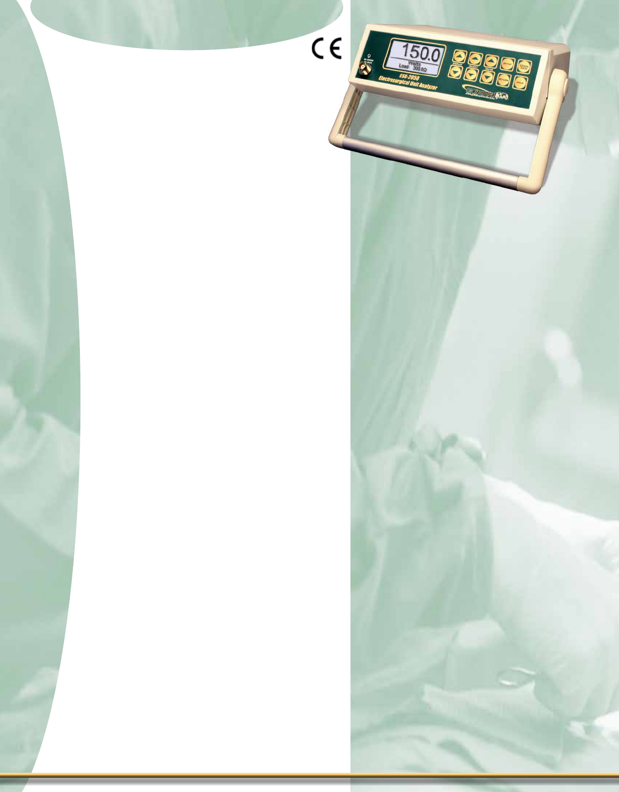
Features - ESU-2300
± Measurements via Industry Standard
Current Sensing Method
± Built-In RF Current Transformer
(Pearson® Coil)
± True RMS Readings Using DFATM
Technology
± Performs Output, RF Leakage & CQM
Tests
± Main Test Loads from 50 to 750 Ohms
In 50 Ohm Steps
± External Test Loads Supported
± Auxiliary Test Load – 200 Ohms
± Independent Variable CQM Test Load
1 to 500 Ohms In 1 Ohm Steps
± Non-Inductive Internal Load Resistors
± GraphicalDisplay With Simultaneous
Details of Parameters & Scrolling
Option Control
± Bright-White Display Backlight
± Rechargeable Battery or Line Powered
Operation
± Isolated Oscilloscope Output
± Full Remote Operation
± USB Port
± Digital Battery Monitor
± Flash Programmable, Field Upgradeable
± Soft Touch Keys With Audible Feedback
The ESU-2300 Analyzer is for users
who prefer a conventional instrument with
internal, selectable test loads. Utilizing the
same Patent-Pending DFATM Technology as
our ESU-2050, the ESU-2300 uses industry
standard current sensing technology rather
than relying on less accurate voltage mea-
surement techniques employed by some
competitive products.
The ESU-2300 uses advanced high-speed
waveform sampling techniques to accurately
analyze even the most complex electrosurgery
generator waveforms. You can easily analyze
Coag waveforms like Desiccate, Fulgurate or
even Spray with the same accuracy as pure
sinusoidal Cut waveforms. RMS current (mA)
and power (watts) can be easily read from
the large LCD graphical display, as well as
other parameters such as mV, mV peak, and
CF. A whisper quiet fan keeps the internal
non-inductive load resistors running cool.
Added features like CQM Testing, RF
Leakage Current measurement, a Rechargeable
Battery, USB and RS232 com ports, oscillo-
scope output, universal power supply and the
ability to easily update the instrument’s rm-
ware in the eld via our unique Flash Update
Utility Software put the ESU-2300 in a class
of its own.
ESU-2300
29
29
1-888-223-6763 - bcgroupintl.com

ESU Analyzer Series
ESU Analyzer Series
sPeCifiCaTions
Flip for product pricing - Page F
Optional: External Load
Precision Power Resistor
(See Page F for a
listing of available values)
The ESU-2300 allows for the use of
External or a combination of Internal &
External Load Resistors to cover ranges
outside the provided Internal Load Range.
Setup Parameters allow the user to tell the
unit about External Loads. This ensures
the continued accurate measurement &
display of power.
inTernal loaD Values noT
exaCTly WhaT you neeD?
Measurement
Method
Industry Standard Current
Sensing, using RF Current
Transformer (Pearson Coil)
Power
Range 1.0 to 400.0 Watts RMS
Resolution 0.1 Watts
Accuracy ± 5% Reading or ± 3 Watts
(whichever is greater)
Current
Range 20 to 2500 mA RMS
Resolution ± 1 mA
Accuracy ± 2.5% Reading or ± 15 mA
Limits
Bandwidth 10 kHz to 10 MHz
Crest Factor 1.4 to 500
Voltage 10,000 V Peak
Main Test Load
Range 50 to 750 Ω
Resolution 50 Ω
Accuracy ± 1% (DC)
Duty Cycle (10 SEC ON, 30 SEC OFF)
Auxiliary Test Load
Fixed 200 Ω
Accuracy ± 1% (DC)
CQM Test Load
Range 1 to 500 Ω
Resolution 1 Ω
Accuracy ± 2% or ± 2 Ω
ESU-2300
Physical
Enclosure High Impact Plastic, UL 94 V-0
Face-Lexan, Back Printed
Size 6.30 x 13.50 x 13.40 inches
160.0 x 342.9 x 340.4 mm
Weight ≤ 17.5 Lbs (7.95 kg)
Electrical
Power Supply
Input: Universal 100-240 VAC, 50-
60 hz
Output: 9 VDC
Battery Sealed Lead Acid
6 VDC, 7.2 AH
General
Display LCD Graphical 240 x 64
Pixels, Backlight
Ventilation Variable speed internal fan
Oscilloscope Output Isolated (uncalibrated), BNC
Connector
Setup Memory EEPROM, All Parameters
Memory Retention 10 years w/o Power
Operating Range 15 to 30 °C (59 to 86 °F)
Storage Range -20 to 60 °C (-4 to 140 °F)
Humidity Limit 20 to 80% RH, Non-Condensing
Connections Communications USB, DB9
Loads: 4mm safety jacks
ESU-2300
30
30
ESU Analyzer Series
ESU Analyzer Series
ESU Analyzer Series
Features - ESU-2050 & ESU-2050P
± True RMS Readings Using DFATM
Technology
± mV, mV Peak, mA, Crest Factor and
Wattage Displays
± Large Graphical Display with
Backlighting & Cursor Selection of
Options and Setup of Parameters
± 1% Measurement Accuracy
± Digital Data Output Via USB and RS232
± Digital Calibration - No Pots to Turn
± Display Contrast is Software Adjustable
± On-Screen Graphical Representation of
Generator Waveform with Scroll &
Zoom Capabilities
± Standard Range Uses 0.1:1 RF Current
Transformer
± Special Low Range Uses 1:1 RF Current
Transformer
± Internally Protected Input Circuitry
± Capture, Store & Print ESU Generator
Output Waveforms with up to 32,768
Discrete Data Points through the
Specialized PC Software
± Internal Data Storage for Three Full ESU
Waveform Data Sets
± Create Customized Load Resistor Table
within the Instrument Based Upon the
Load Resistors Commonly Used
± User Selectable Data Display Screens
± Smallest & Lightest Weight ESU
± Pulsed Output Waveform Compatible
(ESU-2050P Only)
The ESU-2050 ESU Analyzer is the rst
instrument of its kind on the market. Designed
through extensive collaboration with several
of the world’s leading electrosurgery genera-
tor manufacturers (including the worldwide
market leader), the ESU-2050 is a highly
accurate calibration-quality instrument intend-
ed for use by OEM factory technicians and
eld service engineers, as well as customers
who desire to test their ESU generators in the
exact same way the medical device manu-
facturers do. It is the only ESU Analyzer on
today’s market with a 1% of reading level of
accuracy.
DFATM Technology achieves the high level of
accuracy and functionality demanded by ESU
manufacturers worldwide, and replaces the
Fluke® Model 8920A instrument previously
utilized in such applications. The ESU-2050
uses external precision load resistors and an
external wide band toroidal current transform-
er to take industry standard RF current mea-
surements. It can function as a stand-alone
meter or in conjunction with our optional PC
Utility Software.
Measurement data, including RMS current,
RMS voltage, Peak voltage, Power (watts),
and Crest Factor are displayed on a series
of user congurable screens. You can even
display all of these values on a single screen,
including the load resistance. Digitized ESU
waveforms with up to 32,768 data points can
be stored, displayed on screen, or exported
to a PC for analysis. Our companion PC
Utility Software will create an Excel® graph of
even the most complex output waveforms for
viewing.
ESU-2050
ESU Analyzer Series
31
31
1-888-223-6763 - bcgroupintl.com
INPUT COMPATIBILITY
RF Current Transformer (50ohm) Pearson Electronics 411 OR 4100
(Typical)
RF Current Transformer
Attenuation
0.1: 1
1: 1
User Selectable
INPUT RANGE
Voltage (RMS) 2.0 – 700.0 mV RMS
Input Resolution 0.1 mV RMS
Voltage (Peak) 1000.0 mV
Resolution 0.1 mV
Frequency 10 KHz – 10 MHz
Accuracy 1% reading
Maximum Input Voltage 3.3 V p-p
Internally Protected
CALCULATED RANGES
Current (with 0.1:1 CT) 7000 mA RMS
Resolution 1 mA
Current (with 1:1 CT) 700.0 mA RMS
Resolution 0.1 mA
Wattage 10 KHz – 10 MHz
Resolution 0.1 Watt
Crest Factor 1.4 to 500
Resolution 0.1
INPUT IMPEDANCE
50 Ω
DISPLAY LCD Graphical 128 X 64 Pixels
SETUP MEMORY EEPROM, All Parameters
MEMORY RETENTION 10 Years w/o Power
OPERATING RANGE 15 to 30 °C (59 to 86 °F)
STORAGE RANGE -20 to 60 °C (-4 to 140 °F)
CONSTRUCTION Enclosure – ABS Plastic
Face – Lexan, Back Printed
SIZE 3.4” x 9.1” x 8.0”
86.4 x 231.4 x 203.2 mm
WEIGHT ≤ 3 lbs. (1.36 kg)
CONNECTIONS Input: BNC
Output: Serial DB-9 or USB
POWER SUPPLY ADAPTER
Input: Universal 100-240 VAC, 50-
60 Hz
Output: 6 VDC
POWER CONSUMPTION ON: less than 150 mA
OFF: less than 40 µA
DATA STORAGE (Internal) 3 Sets of 32768 Data Points
ESU-2050
page24
ESU Analyzer Series
ESU Analyzer Series
sPeCifiCaTions
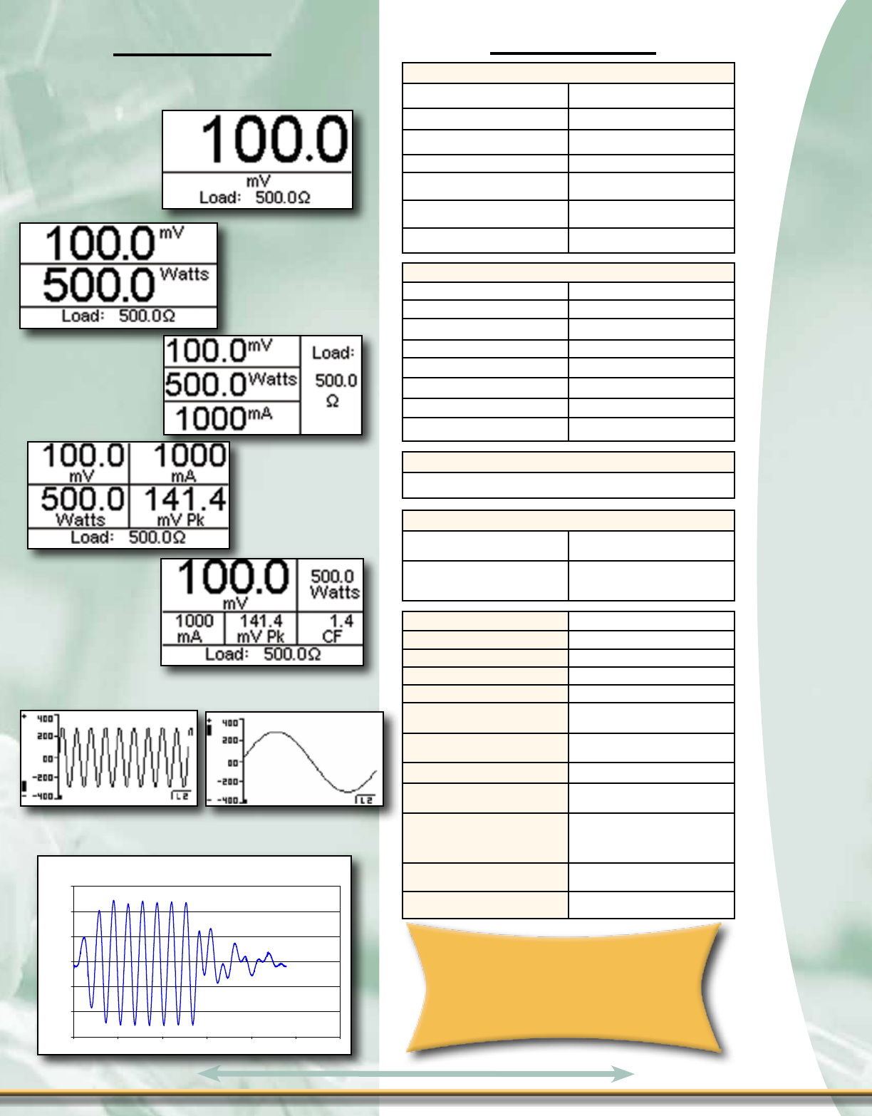
sCreen VieWs
The ESU-2050 & ESU-2400 are
used and recommended
by the world’s leading
electrosurgery generator
manufacturer
Valleylab Force FX Blend Cut Waveform
-600
-400
-200
0
200
400
600
0 500 1000 1500 2000 2500 3000
Sample
Voltage (mV)
One Display Zone Screen
with mV Parameter Selected
Two Display Zone Screen
with mV & Watts
Parameters Selected
Three Display Zone Screen
with mV, Watts & mA
Parameters Selected
Five Display Zone Screen
with mV, Watts, mA, mV
Peak & CF Parameters
Selected
Four Display Zone Screen
with mV, Watts, mA & mV Peak
Parameters Selected
Fully Zoomed Out Fully Zoomed In
ESU-2050 Graph Mode Example
(NOTE: User can select measurement values & locations to
be displayed on each screen choosing from RMS Current,
RMS Voltage, RMS Power, Peak Voltage & Crest Factor)
PC Software Waveform Example created from the
Excel® graphing function using the over 32,000
discrete datapoints exported from the ESU-2050
32
32
Flip for product pricing - Page F
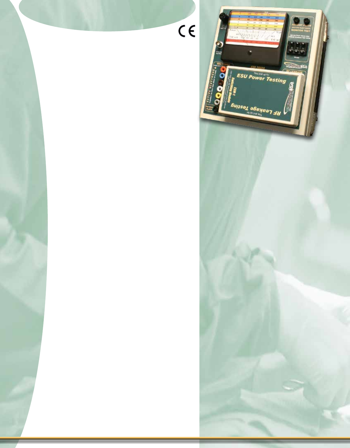
ESU Analyzer Series
ESU Analyzer Series
ESU Analyzer Series
ESU Analyzer Series
Features - ESU-2000A
± Small & Simple to Use
± Lightweight
± 6 Selectable Loads from 50 to 500 ohms
± No Load Switching Relays
± Return Contact Monitor Test with 1 ohm
Steps
± RF Power, Current & Leakage
Measurement
± No Batteries or Power Cords
± Easy-to-Read Color-Coded Meter
± High Speed Fuse Protects Meter
Accessories Included
± ESM-1 Switching Module
± Red, Black & Green Patch Cords
± Insulated Alligator Clips & Ground
adapter
± Spare Fuse
± Operator Manual
The ESU-2000A ESU Tester is full-featured
& versatile.Test modes include RF output
power and leakage, measured with a large
analog meter. There are different color codes
for each range at the input connector and
on the meter, making measurements quick
& easy. For Return Contact Monitor (CQM,
REM, ARM, PSS) testing, we’ve built in a 0
to 1000 ohm variable resistance with 1 ohm
digital resolution. Even more expensive ESU
testers generally don’t offer this much range
or resolution.
To improve reliability and accuracy, the
ESU-2000A has no front-panel switches.
Instead, the user simply changes the position
of our unique ESM-1 Switching Module to
select either RF Power or RF Leakage mode.
For safety, the module also blocks access to
unused input connectors, virtually eliminating
worry about improper connections & resultant
equipment damage. Plus you won’t lose the
switching module because it is conveniently
stored on the front panel at all times.
ESU-2000A
33
33
1-888-223-6763 - bcgroupintl.com

ESU Analyzer Series
ESU Analyzer Series
sPeCifiCaTions
Flip for product pricing - Page E
RF MEASUREMENT
RANGE CURRENT 0 to 1000 mA RMS
POWER 0 to 500 W
ACCURACY CURRENT ± 2% FS
POWER ± 5% FS
FREQUENCY 0 to 10 MHz
FUSE 500 mA Fast-Blow FWH-1/2
OSCILLOSCOPE OUTPUT OUTPUT Isolated, Uncalibrated
CONNECTION BNC (50 Ω)
VARIABLE LOAD
VALUES 50 Ω, 100 Ω, 200 Ω, 300 Ω, 400 Ω
500 Ω
TYPE Non-Inductive
ACCURACY ± 2% ± 1 Ω
POWER RATING
(MAX)
50 Ω 50 W
100 Ω 100 W
200 Ω 200 W
300 Ω 300 W
400 Ω 400 W
500 Ω 500 W
DUTY CYCLE 10 seconds on, 20 seconds off
LEAKAGE LOAD
VALUE 200 Ω
TYPE Non-Inductive
ACCURACY ± 2% ± 1 Ω
POWER RATING 50 W
CONNECTIONS 4mm Banana
RETURN ELECTRODE MONITOR TEST LOAD
RANGE 0 to 999 Ω
RESOLUTION 1 Ω
ACCURACY ± 3% + 3 Ω
CONNECTIONS 4mm Banana
PHYSICAL & ENVIRONMENTAL
DISPLAY 4-1/2” Analog Meter, Color-coded display (W and mA)
CONSTRUCTION ENCLOSURE ABS Plastic
FACE PLATE Back-printed Lexan
SIZE 5.36 x 8.68 x 9.10 Inches(136.1 x 220.5 x 231.1 mm)
WEIGHT ≤4 Lbs (1.82 kg)
OPERATING RANGE 15 to 30 °C (59 to 86 °F) 20 to 80% RH, Non-Condensing
STORAGE RANGE -40 to 60 °C (-40 to 140 °F)
ESU-2000A
34
34
ESU Analyzer Series
ESU Analyzer Series
35
35
Comparison Chart
1-888-223-6763 - bcgroupintl.com
Comparison Chart
Comparison Chart
Models: ESU-2400/H ESU-2300 ESU-2050 ESU-2050P ESU-2000A
Industry-standard
RF current measurement Yes Yes Yes Yes Yes
Test Loads
1 to 6400 Ohms, 1
ohm increments,
internal load bank
50 to 750 Ohms,
50 ohm incre-
ments, internal
load bank
Requires external
precision non-in-
ductive test loads,
1-9999 Ohms
compatible
Requires external
precision non-in-
ductive test loads,
1-9999 Ohms
compatible
50, 100, 200, 300,
400, 500 Ohms
RF Current Range <2 ma to 7,000 mA 20 ma to 2,500 mA <2 ma to 7,000 mA <2 ma to 7000 mA 0 - 1000 mA
RF Power (Watts RMS) Range To 999.9 Watts To 400 Watts To 999.9 Watts To 999.9 Watts To 500 Watts
Bandwidth 50 kHz to 10 MHz 10 kHz to 10 MHz 10 kHz to 10 MHz 10 kHz to 10 MHz 0 - 10 MHz
Display QVGA Color Touch
Screen
260 x 64 pixel LCD
Graphical Display
with Backlight
128 X 64 Pixels
LCD Graphical
with Backlight
128 X 64 Pixels
LCD Graphical
with Backlight
4.5 inch Analog
Meter
External Test Load
Compatible
Yes, can use inter-
nal + external or
external only, or
internal only
Yes, can use inter-
nal + external or
external only, or in-
ternal only
Yes, requires exter-
nal test loads
Yes, requires exter-
nal test loads Yes
External Current Transformer
Required No No Yes Yes No
Continuous Output Waveform
Compatibility Yes Yes Yes Yes Yes
Pulse Output Waveforms
Compatibility Yes No No Yes Yes
Multiple Pulsed Waveforms
Compatibility 2400H Only No No No No
Measurement accuracy 1 % of reading on
RMS Current
2.5 % of reading
on RMS Current, 5
% for reading RMS
Power
1% reading, > 50
mV, up to 1 MHz,
3% reading, > 50
mV, 1 to 10 MHz
1% reading, > 50
mV, up to 1 MHz,
3% reading, > 50
mV, 1 to 10 MHz
±5% of Full Scale
Calibration level accuracy Yes No Yes Yes No
Crest Factor Range 1.4 to 500 1.4 to 500 1.4 to 500 1.4 to 500 N/A
Covidien/Valleylab Force Triad
Calibration Procedure
Compatibility
Yes No Yes Yes No
Covidien/Valleylab Ligasure
Generator Calibration
Compatibility
Yes No Yes Yes No
Number of parameters
measured/displayed 15 5 15 15 x 2
Internal REM/ARM/CQM
Testing
Yes, 500 ohm load
adjustable in 1
ohm increments
Yes, 500 ohm load
adjustable in 1
ohm increments
No, requires exter-
nal CQM Test Box
(CQM-2000)
No, requires exter-
nal CQM Test Box
(CQM-2000)
Yes
Automated power-load curves
Yes, "x" to "y" Ohms
in "z" ohm incre-
ments OR by user-
defined load table
values, multiple
power levels @
each load possible
No No No No

Comparison Chart
Flip for product pricing - Page E-F
ESU Analyzer Series
ESU Analyzer Series
36
36
Comparison Chart
Comparison Chart
Models: ESU-2400/H ESU-2300 ESU-2050 ESU-2050P ESU-2000A
Auto-activation of ESU
generator for power load
curve testing
Yes No No No No
User definable testing
autosequences
Yes, unlimited steps
with unlimited ascii
text description per
step, embedded
measurement
capability within
sequence
No No No No
Communication ports USB, RS232,
Ethernet, PS/2 USB, RS232 USB, RS232 USB, RS232 No
Capture & Store RF
Waveform Yes No Yes Yes No
RF Leakage Current
Measurement Yes Yes
Yes, with external
200 ohm test load
and CT
Yes, with external
200 ohm test load
and CT
Yes
Remote control compatibility
of ESU generator Yes No No No No
User definable data screens Yes Yes Yes Yes No
FLASH field upgrade of
firmware Yes Yes Yes Yes No
Test load temperature
monitor Yes Yes No No No
Oscilloscope Output Jack Yes Yes No No Yes
User-adjustable signal
averaging Yes Yes Yes Yes No
Test form printout Yes No No No No
Browse Internet Yes No No No No
Battery Operation No Yes No No N/A
External keyboard & mouse
compatible Yes No No No No
Fan Cooling of Internal Load
Resistor Bank Yes Yes No No No
Size
7.8 x 15.0 x 22.5
inches
198.1 x 381 x
571.5 mm
6.30 x 13.50 x 13.40
inches
160.0 x 342.9 x
340.4 mm
3.4 x 9.1 x 8.0
inches
86.4 x 231.4 x
203.2 mm
3.4 x 9.1 x 8.0
inches
86.4 x 231.4 x
203.2 mm
5.36 x 8.68 x 9.10
inches
136.1 x 220.5 x
231.1 mm
Weight 31 lbs. (14 kg) ≤ 17.5 lbs (7.95 kg) ≤ 3 lbs. (1.36 kg) ≤ 3 lbs. (1.36 kg) ≤ 4 lbs (1.82 kg)

Pressure Meters
Pressure Meters
Digital Pressure Meter Series
Digital Pressure Meter Series
Features - DPM 2300 Series
± Large Graphics Display With Cursor
Selection Of Options And Setup
± High Resolution 24 Bit Measurement
± ± 0.05% FS Pressure Accuracy
± Standard Pressure Scales Include 13
Different Engineering Unit Ranges
(PSI, mmHg@0 °C, mmHg@20 °C, inHg@0 °C,
inHg@20 °C, cmH2O@20 °C, inH2O@4 °C,
inH2O@20 °C, inH2O@60 °F, kg/cm2, kPa, mBar, Bar)
± MAX And MIN Pressure Value Capture
And Storage
± Digital Calibration & Zero Adjust
± Selectable Display Options & Digit Sizes
± Battery Life Display (0 To 100%)
± Programmable Digital Averaging Filter
± Display Contrast Is Software Adjustable
± Digital Zero Adjustment
DPM-2302 Adds:
± RS232 Serial Communications
Second Pressure Sensor Adds:
± Independent Pressure Channel
± Separate And Combined Display Option
Temperature Option Adds:
± YSI700or100ΩRTDTemperatureProbe
Interface
± -20.0 to 100.0 °C (-4.0 to 212.0 °F) Range
± ± 0.5% FS Accuracy
Analog Output Option Adds:
± DC Output Proportional to the
Displayed Pressure or Temperature
± ± 0.1% FS Output Accuracy
The DPM-2300 Series is a microproces-
sor based, High Precision, High Resolution
Digital Pressure Meter Family. These meters
measure both gas and liquid pressures and
provide multiple engineering unit displays
for the results. The unit may have one or
two pressure sensors and an optional tempera-
ture sensor input to measure pressure and
temperature all in one meter.
There are ve standard pressure ranges.
Models are available with any combination of
ranges. The DPM-2350 Subset provides a
differential pressure option using a single
sensor in any of the ve ranges. Optional
features allow the addition of RS232
communication, Temperature measurement
and DC Analog Outputs.
DPM-2300
37
37
1-888-223-6763 - bcgroupintl.com

Digital Pressure Meter Series
Digital Pressure Meter Series
Flip for product pricing - Page O
DPM-2350
w/Female CPC
PRESSURE MEASUREMENT (GAUGE)
RANGE
100 PSI SENSOR -13.5 TO 100.0 PSI
75 PSI SENSOR -13.5 TO 75.0 PSI
10 PSI SENSOR -10.0 TO 10.0 PSI
5 PSI SENSOR -5.0 TO 5.0 PSI
0.3 PSI SENSOR -0.3 TO 0.3 PSI
RESOLUTION
100 PSI SENSOR 0.001 PSI
75 PSI SENSOR 0.001 PSI
10 PSI SENSOR 0.0001 PSI
5 PSI SENSOR 0.0001 PSI
0.3 PSI SENSOR 0.00001 PSI
MAXIMUM
OVERPRESSURE
100 PSI SENSOR 200 PSI
75 PSI SENSOR 200 PSI
10 PSI SENSOR 45 PSI
5 PSI SENSOR 15 PSI
0.3 PSI SENSOR 5 PSI
ACCURACY ± 0.05% FS
DIGITAL FILTER 0 to 10 seconds, Selectable
COMPATIBLE
MEDIA
Only non-corrosive, non-ionic, or otherwise pure
fluids and/or gases that are compatible with sensor
materials including glass, silicon, ceramic, epoxy,
RTV, gold, aluminum and nickel.
CONNECTIONS See Model Number Breakdown
DPM-2300
PHYSICAL & ENVIRONMENTAL
DISPLAY 128 X 64 Pixels Non-Backlit Graphical LCD
CONSTRUCTION ENCLOSURE ABS Plastic
OVERLAY Back-printed Lexan
SIZE 7.69 x 3.97 x 1.80 Inches
(195.3 x 100.8 x 45.7 mm)
WEIGHT < 1 Lbs (0.45 kg)
OPERATING RANGE 15 to 30 °C (59 to 86 °F)
STORAGE RANGE -40 to 60 °C (-40 to 140 °F)
ELECTRICAL & MISC.
BATTERY 9V Alkaline Battery (ANSI/NEDA 1604A or equivalent)
BATTERYELIMINATOR
9 VDC, 200 mA
BC20-21110 BATTERY ELIMINATOR ( UNIVERSAL)
POWER
CONSUMPTION
ON < 35 mA
OFF < 40 µA
BATTERY LIFE CONTINUOUS 80 hours
OFF 1 year
RS-232
COMMUNICATIONS
BAUD 115200
DATA BITS 8
START BITS 1
STOP BITS 1
PARITY None
HANDSHAKING None
CONNECTIONS
Seven (7) pin Mini-DIN
Receptacle
Pinout:
sPeCifiCaTions moDel summary 38
38
sPeCial moDel:
Recommended model for use with TSI
Certier-FA Respiratory Vent Test System:
DPM-235175NNFC
or DPM-23017510NFC
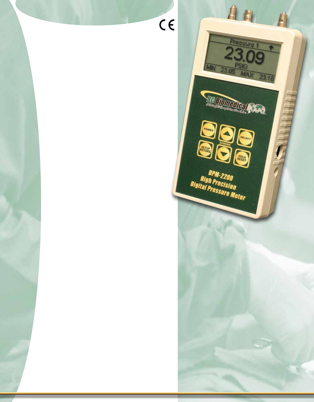
Pressure Meters
Pressure Meters
Digital Pressure Meter Series
Digital Pressure Meter Series
Features - DPM-2200 Series
± Single or Dual Pressure Sensors
± Large Graphics Display with Cursor
Selection of Options & Parameters Setup
± ± 0.05% FS Pressure Accuracy
± 16 Bit Measurement
± Standard Pressure Scales Include 13
Different Engineering Unit Ranges
(PSI, mmHg@0 °C, mmHg@20 °C, inHg@0 °C,
inHg@20 °C, cmH2O@20 °C, inH2O@4 °C,
inH2O@20 °C, inH2O@60 °F, kg/cm2, kPa, mBar, Bar)
± Digital Calibration & Zero Adjust
± Selectable Display Options & Digit Sizes
± Battery Life Display (0 to 100%)
± Programmable Digital Filter
± Display Contrast is Software Adjustable
± Flash Programmable, Field Upgradeable
± Optional DC or High Frequency (up to
100 Hz Cycle Rate) Outputs
± Pressure & Vacuum
± Liquids & Gases
DPM-2202 Adds:
± Min/Max Pressure Value Capture and
Storage
± RS232 Serial Communications
Second Pressure Sensor Adds:
± Independent Pressure Channel
± Separate & Combined Display Option
Temperature Option Adds:
± YSI700or100ΩRTDTemperatureProbe
Interface
± -20.0 to 100.0 °C (-4.0 to 212.0 °F) Range
± ± 0.5% FS Accuracy
Analog Output Option Adds:
± DC Output Proportional to the
Displayed Pressure or Temperature
± ± 0.1% FS Output Accuracy
The DPM-2200 Series is a Microprocessor-
based, High Precision, Digital Pressure Meter
Family. They measure both gas and liquid
pressures and provide multiple engi-
neering unit displays for the results. The
unit may have one or two pressure sensors
and an optional temperature sensor input
to measure pressure and temperature all
in one meter. An analog output option is also
available.
There are ve standard pressure ranges.
Models are available with any combination of
ranges. The DPM-2250 Subset provides a
differential pressure option using a single
sensor in any of the ve ranges. Optional
features allow the addition of RS232
communication, Temperature measurement
and DC Analog Outputs.
DPM-2200
39
39
1-888-223-6763 - bcgroupintl.com
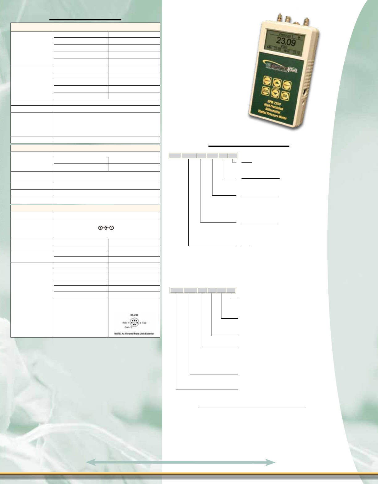
DPM 225X XX N XX XX
Options
Blank = Not Applicable
DC = DC (Direct Current) Analog Output
HF = High Frequency DC Analog Output
Temperature Sensor
N = Not Applicable
Y7 = YSI 700
R1 = 100 Ω RTD
Pressure Sensor 2
N = Not Applicable
Pressure Sensor 1
N = Not Applicable
100 = Max 100 PSI (CPC Connector)
75 = Max 75 PSI (CPC Connector)
10 = Max 10 PSI (Luer Connector)
5 = Max 5 PSI (Luer Connector)
.3 = Max .3 PSI (Luer Connector)
2250 Series
2251 = Basic Model (Includes Min/Max)
2252 = RS232 Add
Digital Pressure Meter
3
Use the following model configuration guide to construct or decode a DPM220X series
differential Digital Pressure Meter model number:
DPM
220X
XX
XX
XX
XX
Options
Blank = Not Applicable
DC = DC (Direct Current) Analog Output
HF = High Frequency DC Analog Output
Temperature Sensor Option
N = Not Applicable
Y7 = YSI 700
R1 = 100 Ω RTD
Pressure Range (Sensor 2)
N = Not Applicable
100 = Max 100 PSI
75 = Max 75 PSI
10 = Max 10 PSI
5 = Max 5 PSI
.3 = Max 0.3 PSI
Pressure Range (Sensor 1)
100 = Max 100 PSI
75 = Max 75 PSI
10 = Max 10 PSI
5 = Max 5 PSI
.3 = Max 0.3 PSI
Model
2201 = Basic Model
2202 = Adds Min/Max and RS-232
MODEL INFORMATION
Digital Pressure Meter Series
Digital Pressure Meter Series
sPeCifiCaTions
Flip for product pricing - Page P
moDel summary
DPM-2250
OPTIONAL ACCESSORIES FOR DPM SERIES
40
40
PRESSURE MEASUREMENT (GAUGE)
RANGE
100 PSI SENSOR -13.5 TO 100.0 PSI
75 PSI SENSOR -13.5 TO 75.0 PSI
10 PSI SENSOR -10.0 TO 10.0 PSI
5 PSI SENSOR -5.0 TO 5.0 PSI
0.3 PSI SENSOR -0.3 TO 0.3 PSI
RESOLUTION
100 PSI SENSOR 0.01 PSI
75 PSI SENSOR 0.01 PSI
10 PSI SENSOR 0.001 PSI
5 PSI SENSOR 0.001 PSI
0.3 PSI SENSOR 0.0001 PSI
ACCURACY ± 0.05% FS
DIGITAL FILTER 0 to 10 seconds, Selectable
COMPATIBLE
MEDIA
Only non-corrosive, non-ionic, or otherwise pure
fluids and/or gases that are compatible with sensor
materials including glass, silicon, ceramic, epoxy,
RTV, gold, aluminum and nickel.
CONNECTIONS Male Luer Coupler
DPM-2200
PHYSICAL & ENVIRONMENTAL
DISPLAY 128 X 64 Pixels Non-Backlit Graphical LCD
CONSTRUCTION ENCLOSURE ABS Plastic
OVERLAY Back-printed Lexan
SIZE 7.69 x 3.97 x 1.80 Inches
(195.3 x 100.8 x 45.7 mm)
WEIGHT < 1 lbs (0.45 kg)
OPERATING RANGE 15 to 30 °C (59 to 86 °F)
STORAGE RANGE -40 to 60 °C (-40 to 140 °F)
ELECTRICAL & MISC.
BATTERY 9V Alkaline Battery (ANSI/NEDA 1604A or equivalent)
BATTERYELIMINATOR
9 VDC, 200 mA
BC20-21110 BATTERY ELIMINATOR ( UNIVERSAL)
POWER
CONSUMPTION
ON < 35 mA
OFF < 40 µA
BATTERY LIFE CONTINUOUS 80 hours
OFF 1 year
RS-232
COMMUNICATIONS
BAUD 115200
DATA BITS 8
START BITS 1
STOP BITS 1
PARITY None
HANDSHAKING None
CONNECTIONS
Seven (7) pin Mini-DIN
Receptacle
Pinout:
BC20 - 21110 BATTERY ELIMINATOR (UNIVERSAL)
BC20 - 41361 RS232 COMMUNICATION CABLE, USB(A)M TO MINI DIN MALE
BC20 - 30106 BC BIOMEDICAL SMALL SOFT SIDED CARRYING CASE
BC20 - 01005 UNIVERSAL PRESSURE ADAPTER KIT
BC20 - 01006 YSI TEMPERATURE PROBE
BC20 - 01008 RTD (100 Ω) TEMPERATURE PROBE

Pressure Meters
Pressure Meters
Digital Pressure Meter Series
Digital Pressure Meter Series
Features - DPM-2000 Series
± Pressure Ranges:
- 13.50 to 100.00 PSI
- 701 to 5190 mmHg @ 20 °C
- 951 to 7043 cmH2O @ 20 °C
- 374 to 2773 inH2O @ 20 °C
± ± 0.1% FS Pressure Accuracy
± 5 Digit LCD Display
± Programmable Digital Filter
± Digital Calibration & Zero Adjust
± Male Luer Connector
± Battery Life Display (0 to 100%)
± Liquids & Gases
DPM-2001PLUS Adds:
± Min/Max Value Capture
± RS232 Serial Communications
DPM-2100 Adds:
± YSI-700 Temperature Probe Interface
± 0.0 to 100.0 °C (32.0 to 212.0 °F) Range
± ± 0.5% FS Accuracy
The DPM-2000 Series is a Microprocessor
based Family of Meters that offers not only
positive and negative pressure sensing of
compatible liquids and gases, but also has
models with Temperature and RS232.
The DPM-2001 is the base model. The
DPM-2001PLUS adds a “Min/Max” feature
plus a RS232 port. The top-of-the-line DPM-
2100 is a pressure/temperature meter. It
has all the features of the PLUS model and
also includes a YSI 700 temperature probe
interface.
Each model has a battery life display (0 to
100%), Software adjustable LCD contrast,
digital calibration (no pots to turn), .1% of full
scale accuracy, -13.50 to 100.00 PSI range,
digital zero adjust and four pressure scales:
PSI, inH2O, cmH2O and mmHg.
DPM-2001PLUS
41
41
1-888-223-6763 - bcgroupintl.com

Digital Pressure Meter Series
Digital Pressure Meter Series
sPeCifiCaTions
moDel summary
DPM-2001
DPM-2100
Flip for product pricing - Page P
BC Model Description
DPM-2001 Basic Unit
DPM-2001PLUS Basic Unit + Capture and RS232
DPM-2100 Basic Unit + Capture, RS232 and Temp
Optional Accessories
BC20 - 21110 Battery Eliminator (Universal)
BC20 - 21102 RS232 Communication Cable
BC20 - 30106 Soft Carrying Case
BC20 - 01005 Universal Adapter Kit
PRESSURE
RANGE
-13.50 to 100.00 PSI
-701 to 5190 mmHg @ 20 °C
-374 to 2773 inH2O @ 20 °C
-951 to 7043 cmH2O @ 20 °C
RESOLUTION
0.01 PSI
1 mmHg @ 20 °C
1 inH2O @ 20 °C
1 cmH2O @ 20 °C
MAXIMUM
OVERPRESSURE 200 PSI
ACCURACY ± 0.1% FS
DIGITAL FILTER 1 – 255 samples
COMPATIBLE
MEDIA
Only non-corrosive, non-ionic, or otherwise pure
fluids and/or gases that are compatible with sensor
materials including glass, silicon, ceramic, epoxy,
RTV, gold, aluminum and nickel.
CONNECTIONS Male Luer Coupler
DPM-2000
PHYSICAL & ENVIRONMENTAL
DISPLAY 5 Digit, 7-Segment Non-Backlit LCD
CONSTRUCTION ENCLOSURE ABS Plastic
OVERLAY Lexan, Back Printed
MEMORY SETUP EEPROM, All Parameters
RETENTION 10 Years w/o Power
SIZE 7.69 x 3.97 x 1.82 Inches (195.3 x 100.8 x 46.2 mm)
WEIGHT ≤ 1 Lbs (0.45 kg)
OPERATING RANGE 0 to 50 °C (32 to 122 °F)
STORAGE RANGE -40 to 60 °C (-40 to 140 °F)
ELECTRICAL & MISC.
BATTERY 9V Alkaline Battery (ANSI/NEDA 1604A or equivalent)
BATTERY
ELIMINATOR
9 VDC, 200 mA
BC20-21110 BATTERY ELIMINATOR (UNIVERSAL)
POWER
CONSUMPTION
ON < 15 mA
OFF < 40 µA
BATTERY LIFE CONTINUOUS 80 hours
OFF 1 year
RS-232
COMMUNICATIONS
BAUD 115200
DATA BITS 8
START BITS 1
STOP BITS 1
PARITY None
HANDSHAKING None
CONNECTIONS
1/8 Stereo Receptacle
for use with
BC20-21102 RS-232
Cable
42
42

Pulse Oximetry Testing
Pulse Oximetry Testing
Features - FingerSimsTM
± Easy to Use SpO2 Simulator
± Quick Testing of Pulse Oximetry
Systems including Sensors
± 80, 90 & 97% Saturation Levels
± Inexpensive & Accurate
Features - MSP-2100
± Accepts the FingerSimsTM to Provide
SpO2 Outputs
± Pulse Synchronized with PS-2100,
PS-2200 & NIBP-1000 Series Products
via Aux Port
± Powered via Aux Port
Features - SPO-2000
± Accepts the FingerSimsTM to Provide
SpO2 Outputs
± 30, 60, 90, 120, 150 & 180 BPM Pulse
Rates
± External AC Adapter
± Compact & Cost-Effective
± Maintenance Free
Pulse Oximetry Testing
Pulse Oximetry Testing
MSP-2100
with FingerSimsTM
The SPO-2000 is a stand-alone device that pro-
vides a calibrated pulse rate for the FingerSimsTM.
This allows the FingerSimsTM to be used as a
hands-free test system. (FingerSimsTM Required,
but Not Included.)
The MSP-2100 can plug into the Auxiliary port of
BC Biomedical’s PS-2100, PS-2200 & the NIBP-
1000 Series providing a calibrated pulse rate.
(FingerSimsTM Required, but Not Included.)
SPO-2000
with FingerSimsTM
43
43
1-888-223-6763 - bcgroupintl.com
The FingerSimsTM tests your SpO2 monitor
and nger sensor as a system and works very
similar to a human nger, providing for variable
absorption and reectance of visible red and
infrared light. The dye-based technology of the
FingerSimsTM is a proven simulation technique for
generating accurate SpO2 saturation levels. Plus
FingerSimsTM work with any style Pulse Oximetry
Finger Sensor. The FingerSimsTM provide SpO2
outputs of 80, 90 & 97%. Simply push on the
FingerSimsTM to generate a “pulse” or include a
calibrated pulse rate by adding the SPO-2000 or
the MSP-2100 Pulse Oximetry Module.
FingerSimsTM
Replacement Set
FS-1000RS

fingersims sPeCifiCaTions
Pulse Oximetry Testing
Pulse Oximetry Testing
Flip for product pricing - Page I
80%
?%
BC Biomedical
FingerSimsTM
Wouldn’t it be nice to have
calibrated fingers?
FingerSimsTM Starter Kit
FS-1000-SK
NIBP-1010 with MSP-2100 & FingerSimsTM
PS-2110 with MSP-2100 & FingerSimsTM
MSP-2100 sPeCifiCaTions
SPO-2000 sPeCifiCaTions
90%
97%
Tm
Saturation Nominal Values 80,90 & 97%
These are the nominal Red-to-Infrared Ratios (AC)
@ 72.5 F & 660 nM/910 nM
Light Absorption Infrared: 10 to 40 dB
Red: 15 to 40 dB
Typical Infrared Percent 0 to 5%
Modulation when Squeezed
Long Term Storage Temp Range 32 to 104 °F
Operating Temp. 65 to 90 °F
Accuracy ±1 BPM
Power Aux Port
Weight ≤ 1 Lbs (0.45 kg)
Size 2.3 x 3.6 x 1.5 Inches
?%
Accuracy(Rate) ± 1%
Power AC Adapter
Weight ≤ 1 Lbs (0.45 kg)
Size 5.2 x 5.2 x 2.5 Inches
(132.1 x 132.1 x 63.5 mm)
44
44
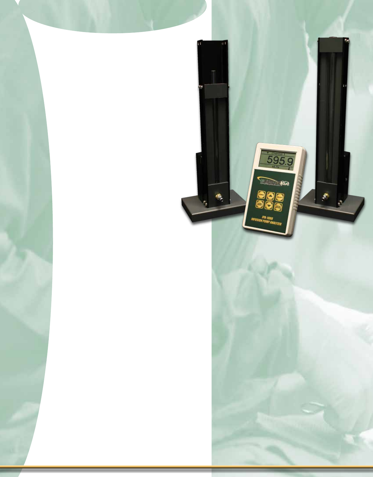
Infusion Pump Analyzer
Infusion Pump Analyzer
Infusion Pump Analyzer
Infusion Pump Analyzer
IPA-1000
The IPA-1000 Infusion Pump Analyzer
Family is designed to test the ow rates of
intravenous infusion pumps to ensure their
correct operation. It is able to test up to
two pumps simultaneously by the volumet-
ric method in milliliters per hour. All tests
are controlled by a Microprocessor, which
calculates and displays the results.
The uid path is unobstructed, making
them easy to clean. The tubes are plastic,
not glass so they are rugged. The cables
and chambers are interchangeable. The
unit auto-identies each chamber when it
is plugged in. The chamber calibration is
stored electronically in each chamber, so
all units are interchangeable. This unit is
designed to be tough, simple, portable & very
user friendly.
3.5 mL
Chamber
35 mL
Chamber
45
45
1-888-223-6763 - bcgroupintl.com
Features - IPA-1000 Series
± Easy to Use
± Easy to Clean
± Simultaneous Operation of Two
Chambers
± Large Graphics Display with Cursor
Selection of Options & Setup of
Parameters
± Auto Chamber Recognition
± 2 Chamber Sizes (3.5 & 35 mL)
± Out of Sequence Sensing
± Battery Display (0 to 100%)
± Similar Function to Dynatech Nevada
Model 404A
± Ranges 0 to 999.9 mL/hr & 0 to 9999 mL/hr
± ± 1% of Reading Flow Accuracy
± Digital Calibration – No Pots to Turn
± Software Adjustable Contrast
± Replaceable Tubes
± Sealed Level Sensors
± Programmable End of Test Audio
± Programmable Auto or Manual Test
Start
Optional
± Battery Eliminator

Infusion Pump Analyzer
Infusion Pump Analyzer
moDel summary sPeCifiCaTions
Flip for product pricing - Page J
BC Model Description
BC10-03103 IPA-1000, (1) 3.5 mL Chamber,
(1) Interconnect cable
BC10-03104 IPA-1000, (1) 35 mL Chamber,
(1) Interconnect cable
BC10-03105 IPA-1000, (2) 3.5 mL Chambers,
(2) Interconnect cables
BC10-03106 IPA-1000, (2) 35 mL Chambers,
(2) Interconnect cables
BC10-03107 IPA-1000, (1) 3.5 mL Chamber,
(1) 35 mL Chamber,
(2) Interconnect cables
Individual Components
IPA-1000 Infusion Pump Analyzer Base Unit
MC3.5-1000 3.5 mL Chamber
MC35-1000 35 mL Chamber
Optional Accessories
BC20-30109 Soft Carrying Case
BC20-40607 IPA-1000 Interconnect Cable
BC20-21110 Battery Eliminator (Universal)
Optional Soft Carrying Case
shown with Chambers mounted in
shock-resistant inserts. Analyzer
& Accessories may be stored in
upper compartment.
46
46
Flow Rate Tests
±Performs two independent tests simultaneously
±Controls tests automatically, starting, stopping &
resetting according to the position of uid in chamber
±Ranges: Automatically selected when chamber is
plugged in 0-999.9 mL/hr with 3.5 mL chamber 0-
9999 mL/hr with 35 mL chamber
± Accuracy: Volumetric chamber: 3.5 or 35 mL(nominal)
Overall: ± 1% of reading ± 1 digit
Display
±Graphic LCD, 128 X 64 pixel
Power Requirements
±9V Alkaline
±Optional AC adapter
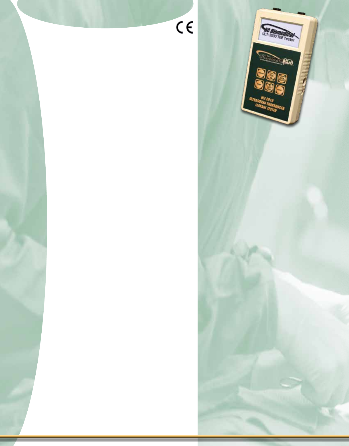
Ultrasound Leakage Tester
Ultrasound Leakage Tester
Ultrasound Leakage Tester Series
Ultrasound Leakage Tester Series
Features - ULT-2000 Series
± Tests the Upper & Lower Leakage
Current Limits per Ultrasound Mfr.
Specications
± Range 0.5 to 500 µA - Designed to Meet
Mfr.TransducerSpecications
± Large Graphic Display with Backlighting
Allows Easy Selection of Options &
Setup of Parameters
± User-Selectable Challenge (Test)
Voltage (90 to 275 VAC) & Frequency
(50 or 60 Hz)
± User-Selectable Test Limits
± Programmable Test Limits Based on
Ultrasound Transducer Mfr. & Type
± ±1% F.S. Range Accuracy
± Auto Ranging for Enhanced Accuracy
Over Entire Range
± Single Button Press for Full System Test
± Selectable Pass/Fail or Numerical Test
Results
± User-Selectable Display Options
± Programmable Backlight Timer
± Flash Programmable, Field Upgradeable
± Compatible with Dale Technology® &
Fluke Biomedical® Adapters & Probes
± RS232 Interface
± PCUtilitySoftwareforConguration
Setup & Remote Control
± Test Results Printable w/Optional Printer
± On-Board Clock & Calendar Function
for Date/Time Stamp of Test Records
± On-Board Storage for up to 99 Test
Records
± Meter Mode
± Audio-Visual Test Status Indication
ULT-2000
The ULT-2000 Series is specically designed
to test the electrical safety of all types of
diagnostic ultrasound transducers, totally
independent of the ultrasound machines
on which they are typically used. Although
the ULT-2000 can be used on virtually any
type of ultrasound transducer, it is espe-
cially recommended in the testing of TEE
(Transesophageal Echocardiography) trans-
ducers prior to each use; as recommended
by many TEE ultrasound device manufactur-
ers. The ULT-2000 tests the integrity of the
outer insulation barrier of the transducer as
well as the capacitive leakage currents that
exist.
The ULT-2000 Series is the most advanced
instrument of its kind on the market today
and adds a totally new dimension to diag-
nostic ultrasound transducer electrical safety
testing.W ith features and functionality that
far surpasses competitive products from
other manufacturers, the ULT-2000 is easy
to set up and use. Operating modes include
a simple PASS/FAIL mode as well as a
QUANTITATIVE mode that offers actual
readings. You can print test results to an
optional printer.
Compatibility with Dale Technology®
DALE800, Fluke Biomedical® ULT800 adapt-
ers and Dual Conductivity Probes allow
you to upgrade to the very latest tech-
nology platform, while safeguarding your
prior investment in adapters and probes. A
wide variety of BC Biomedical adapters and
accessories are available.
47
47
1-888-223-6763 - bcgroupintl.com
Are You IAC
Section 2.2.3B
Compliant?

Ultrasound Leakage Tester Series
Ultrasound Leakage Tester Series
Source Voltage 90 to 275 VAC, ± 1% FS
Leakage Current
0.50 to 10.00 µA, ± 0.5 µA
10 to 250 µA, ± 1% FS
250 to 500 µA, ± 1% FS
Conductivity Current 0.5 to 500 µA, ± 1% FS
Display LCD Graphical w/Backlighting
128 x 64 Pixels
Setup Memory EEPROM, All Parameters
Memory Retention 10 years w/o Power
Operating Range 15 to 30 °C (59 to 86 °F)
Storage Range -40 to 60 °C (-40 to 140 °F)
Construction Enclosure - ABS Plastic
Face - Lexan, Back Printed
Size 7.27 x 3.97 x 1.80 Inches
(184.7 x 100.8 x 45.7 mm)
Weight < 1.1 lbs (0.68 kg)
Power Consumption On: < 300 mA
Off: < 250 µA
Battery 9V Lithium
(ANSI/NEDA 1604LC or equivalent)
Battery Life
Continuous: > 100 Full Tests
(Note: Backlight set to OFF)
OFF: > 1 Year
Battery Eliminator (Optional) BC20-21110 Battery Eliminator
(Universal)
ULT-2000
sPeCifiCaTions
Flip for product pricing - Page C
DUT Information
Manufacturer: Model
Progress Indicator
Test Measurements
Test Procedure:
SOURCE TEST to verify voltage
used during test.
CIRCUIT TEST to verify
measurement circuitry.
BATH CONDUCTIVITY TEST to
validate cleaning solution.
PROBE LEAKAGE TEST to
measure the leakage current of
the DUT.
BC20-42300
Optional
ULT-2000 Printer
sCreen VieWs
Typical Passing Results Display Choices
Test your TEE Transducers While
They are being Disinfected in a Commercial Cleaner
Typical Passing Results Display
Typical Failed Results Display
Pass/Fail ModeQuantitative Mode
or
Quantitative Mode & Pass/Fail Mode
Typical Test Setup for Testing Your Ultrasound Transducers with a
Transducer-SpecicAdapter&aSoakTray.
ULT-PA-29 Adapter
40
48
Ultrasound Transducer Adapter Cross Reference
Ultrasound Leakage Tester Series
Ultrasound Leakage Tester Series
To download the current cross reference sheet in PDF format, go to:
http://testequipmentandtools.com/acatalog/ULT2000SeriesReference.pdf
49
49
BC Adapter
Part # Manufacturer Transducer Compatibility Ultrasound
Platform
Connector
Key
ULT-PA-10 Siemens/ Acuson V5M (TEE), V7M (TEE), EV8-C4, etc. Sequoia
Micro-pinless (PC board)
ULT-PA-11 SonoSite ICT7-4, ITC8-5, C60, etc. 180/180+, Titan
Micro-pinless (PC board)
ULT-PA-12 Siemens 6.5EV13, EC9-4, etc. Call for Details
260-pin ITT Cannon ZIF
ULT-PA-13 Siemens/ Acuson
Acuson/Siemens 156-pin and V510B
Transducers, and ATL UM4, UM9 and ATL
5MHz Bi Plane
128XP 156-pin ITT Cannon ZIF
ULT-PA-14 Philips/ATL HP/Agilent/Philips 21311A, 21369A,
21378A, 21381A Transducers
Philips/HP 4500,
Sonos 5500/7500
260-pin ITT Cannon ZIF
ULT-PA-16 GE
GE LogiQ (for use with GE LogiQ Trans-
ducers 3, 5, 7, 9 and GE Vivid Transduc-
ers 3, 5, 7, 6T, 9T and GE P9603AU
Transducers), 6T (TEE), 9T (TEE), E8C)
LOGIQ, Vivid &
GE P9603AU
260-pin ITT Cannon ZIF
ULT-PA-17 Philips/ATL
Philips iE33 and iU22 diagnostic ultra-
sound TEE transducers - S7-2 (TEE), S7-
3t (TEE), S3-1, C8-4v, C9-5, etc. with
belled housing
iE33/iU22
260-pin ITT Cannon ZIF
ULT-PA-18 Philips/HP
HP/Agilent/Philips (no center post on
transducer connector) 21202A, 21364A,
21365A, 21366A, 21367A Transducers
Call for Details Micro-pinless (PC board)
1-888-223-6763 - bcgroupintl.com
Flip for product pricing - Page C
Ultrasound Leakage Tester Series
Ultrasound Leakage Tester Series
To download the current cross reference sheet in PDF format, go to:
http://testequipmentandtools.com/acatalog/ULT2000SeriesReference.pdf
BC Adapter
Part # Manufacturer Transducer Compatibility Ultrasound
Platform
Connector
Key
ULT-PA-19 Philips All Philips CX50 Laptop System based
transducers CX50 Platform
260-pin Tyco Electronics Mini
Connector
ULT-PA-20 Acuson/ Toshiba
Acuson/Toshiba (for use with Acuson/
Siemens XP, Aspen, Capasee, 3-Needle
Guide C3 Transducers; ATL 3.5 DFT
Transducers; Toshiba PSF-37HT and F
Series Transducers)
Toshiba PVF Series,
2B701-753E, etc. 156-pin ZIF
ULT-PA-21 Hitachi HI VISION 900, 5500, 6500, 8500, EUB-
2000, EUB-525, EUB-405 Plus
EUP-ES52M, EUP-
Series Probes in
general
260-pin ITT Cannon ZIF
ULT-PA-22 Ultraschallkopf -
Aloka
UST-934N/9395, UST-945BP/945BP,
ASU-32-3-M, ASU-32-WSJ, UST-
556/5512, UST-5514DTU
SSD-620, SSD-650
260-pin ITT Cannon ZIF
ULT-PA-23 ALL ALL Transducers All Platforms ALL Congurations
ULT-PA-24 Philips/ ATL L7-4 and similar 260-pin transducers with
belled housing Call for Details
260-pin ITT Cannon ZIF
ULT-PA-25 GE GE LogiqBook Probes - GE VIVID I 6T,
9T, etc. Probes Vivid
260-pin Tyco Electronics Mini
Connector
ULT-PA-26 Acuson For use with Acuson/Siemens 360-pin
Transducers Antares
360-pin ITT Canon ZIF
ULT-PA-27 GE GE YMS/RT (for use with GE YMS/RT
Transducers) Call for Details Call for Details
ULT-PA-29 Zonare Zonare Medical Systems (all transduc-
ers) All Zonare Platforms
168-pin Proprietary Custom
Connector
ULT-PA-30 GE Vivid E9 GE Vivid E9 Call for Details
50
50
Ultrasound Transducer Adapter Cross Reference
Ultrasound Leakage Tester Series
Ultrasound Leakage Tester Series
“Soft Touch” ULT Adapter Family Continues to Grow
Old Rubber Pad
New “Soft Touch” Connector
Did you know that all ultrasound transducer
adapters are not created equally? There are
basically two types of adapters available in
the market today. The traditional adapters
available from other manufacturers utilize
a conductive rubber pad within a rigid body
that captures the center mounting post of
the transducer and pushes the pins of the
transducer electrical connector into the sur-
face of this relatively rigid conductive rub-
ber pad. This action creates stress on the
individual pins of the transducer connector
and can actually bend or break pins under
certain conditions.
Ultrasound manufacturers are aware of the
existence of this type of adapter, and they
will typically not provide warranty repairs to
transducers with bent or broken pins caused
by the use of these adapters. In fact, most
ultrasound manufacturers frown upon the
use of this type of adapter because of the
physical stress placed upon the pins of
the electrical connector. Replacement of a
transducer electrical connector due to bent
or broken pins can be a very costly experi-
ence.
The ULT line of second generation “Soft
Touch” transducer adapters, available from
BC Group International, completely elim-
inates the possibility of costly damage.
Our second generation adapters utilize the
actual multi-pin mating connector for the
ultrasound transducer to be tested. The
transducer electrical connector is subjected
only to the same level of insertion and lock-
ing force that is normally seen when the
transducer is connected to the ultrasound
machine. There are no other undesired
mechanical forces on the transducer electri-
cal connector, or the individual pins within it.
So why not take steps to avoid unnecessary
and costly transducer electrical connector
damage as a result of using older genera-
tion adapters? Second generation improved
design adapters are now available from BC
Group International.
51
51
1-888-223-6763 - bcgroupintl.com

Ultrasound Leakage Tester Series
Ultrasound Leakage Tester Series
Flip for product pricing - Page C
Ultrasound Transducer Adapter Reference
ULT-PA-10 ULT-PA-11 ULT-PA-12 ULT-PA-13
ULT-PA-14 ULT-PA-16 ULT-PA-17 ULT-PA-18
ULT-PA-19 ULT-PA-20 ULT-PA-21 ULT-PA-22
ULT-PA-23 ULT-PA-24 ULT-PA-25 ULT-PA-27
52
52
ULT-PA-29 ULT-PA-30 ULT-PC-10 ULT-PC-15
Conductivity Probes
ULT-PC-20 ULT-PC-25 ULT-PC-30

Ultrasound Wattmeters
Ultrasound Wattmeters
Features - USP-100A
± Digital Reading
± Continuous or Pulsed Power
± Integrated Carrying Case
± 0.2 to 30.0 Watt Range
± Accuracy = ± 3%+One Count Reading
± 0.5 to 10 MHz Frequency Response
± 3” Max Transducer Diameter
± Built-in Transducer Holder
± Degassed Water is the Testing Medium
± Line Power or Battery Operation
Features - USP-50SP
± Digital Reading
± 0 to 30 Watts Range
± ± 3% + One Count Accuracy
± 2.5 Second Integration
± 0.05 Watt Display Sensitivity
Features - USP-30
± Analog Reading
± 0.15 to 30.0 Watt Range
± Continuous or Pulsed Power
± 1 to 10 MHz Frequency Response
± Integrated Carrying Case
± Built-in Transducer Holder
Ultrasound Wattmeters
Ultrasound Wattmeters
USP-100A
The USP-100A Ultrasound Power Meter
was developed to test therapeutic trans-
ducers according to AIUM, JCAHO, FDA
and NIST guidelines. The compact and light
weight USP-100A meets all the require-
ments of a portable test instrument with the
reliability and proven performance of the
Series.
The USP-50SP is designed to measure
the ultrasound power output of diagnos-
tic or therapeutic transducers up to 30
watts. The water tank requires only one pint
of de-gassed distilled water. If de-
gassed water is not available, use distilled
water. The principle of measurement is the
radiant force method.
The USP-30 is designed to measure the
ultrasonic power output of diagnostic or
therapeutic transducers up to 30 Watts using
the radiation force balance method. The
USP-30 consists of a precision mechanical
balance, which measures from 0.01 to 10.00
grams, a conical target suspended on a
triangular hanger, a water tank, a transducer
support rod with clamp and a carrying case.
The transducer to be tested is center mount-
ed over the conical target with the trans-
ducer’s radiating area immersed facedown
in the water medium. This system provides
a sturdy instrument with good measurement
accuracy and economical cost.
53
53
1-888-223-6763 - bcgroupintl.com

Ultrasound Wattmeters
Ultrasound Wattmeters
USP-100A sPeCifiCaTions
Flip for product pricing - Page L
USP-50SP sPeCifiCaTions
Power Range 0 to 30 Watts
Resolution + 50 mW, ± .01 gram
Minimum Detectable Power 0.05 Watts
Display Sensitivity 0.05 Watts
Accuracy ± 3% @10 Watts
Stabilization 2.5 Second Integration
Maximum Transducer Diameter 4 1/2” Inches
Transducer Operating Frequency 0.5 to 10 MHz
Test Media Degassed Water
Display 7 segment 6 Digit 0.6”
(15mm) high LCD
Battery 4-AA: battery life over 40 hrs.; “Lo-Bat” Indicator
Power Supply 120 VAC to 12 VAC 500 mA adapter with 6 Ft. cord
Size 7.0” x 10.5” x 8.5” (H x L x W)
Weight 10 Lbs
USP-30 sPeCifiCaTions
Power Range 150 mW to 30 Watts
Resolution ± 150 mW
Minimum Detectable Power Level ± 150 mW
Minimum Accuracy ± 5%
Expected Accuracy ± 4%
Display Vernier Dial
Display Sensitivity ± 0.01g or ± 150mW
Zeroing Method Manually Adjusted
Test Tank Lining 0.5” neoprene rubber
Test Medium Degassed,
distilled water at normal room temp
Test Tank Liquid Capacity 1,350 mL
Test Tank Dimensions Outside 5.75” Dia. x 5.55”
Inside 4.5” Dia. x 5.25” D
Cone Target 3.5” Dia. x 2” H
Dimensions(w/Case) 19” H x 17” L x 7” W
Power Not required
Weight(w/Case) 18 Lbs
Measure Range 0.2 to 30 Watts
Resolution ± 200 mW
Accuracy ± 3% +One Count Reading
Transducer Frequency 0.5 to 10 MHz
Maximum Transducer Diameter 3”
Test Medium Degassed, distilled water
at normal room temp
Stabilization Time 2.5 sec
Display 3-Digit LCD, 1.3” High
Line Power 120 or 240 VAC Plug-in AC Adapter
Battery 4-AA, 20 hrs. continuous battery life
Dimensions 8.5” H x 12” L x 8.75” W
Weight 11 Lbs
54
54

Dew Point Meter
Dew Point Meter
Features - AMM-15
± Microprocessor Based Portable Battery
Operated Instrument
± Digital Display - 40 to +80 °F Dew Point
± ± 2 °F From + 20 TO +80 °F
± ± 4 °F From - 40 TO +20 °F
± Samples Compressed Air Up to
120 PSIG
± Quick Connect Fittings, Connection
Tubing and Other Adapters Supplied
± Utilizes Connect Fittings, Filter,
Connection Tubing and Other Adapters
Supplied
± Utilizes HC-610 Thin Film Polymer
Integrated Water Vapor Sensor
± RS-232 Computer Interface, Data Logger
± Logs 2,860 Readings, Selectable
Logging Rate
Dew Point Meter
Dew Point Meter
AMM-15
AMM-15 portable Dew Point Meter(Air-Line
Moisture Monitor) is designed to measure
the performance of drying systems for air,
nitrogen and other compressed gases.
The model AMM-15 measures dew point
by utilizing microprocessor circuitry to con-
vert the voltage output of OHMIC’s HC-610
precision water vapor sensor and a tem-
perature sensor to dew/frost point tempera-
ture by the use of psychrometric equations.
Assembled in a rugged hand-held ABS
plastic enclosure and equipped with quick
disconnect tubing couplings and an internal
sensor manifold. An orice maintains line
pressure for true pressure dew point read-
ings. Air or industrial gases are sampled
from receivers, pipes, and hoses up to 120
PSIG and 185ºF.
In addition, heat sink tubing is available for
sampling from drying systems and ovens up
to 550ºF ( depending on ambient tempera-
ture). The AMM-15 can also be connected to
a vacuum pump for sampling from piping,
ovens, tanks or manifolds operating at ambi-
ent or low pressure.
55
55
1-888-223-6763 - bcgroupintl.com

Dew Point Meter
Dew Point Meter
56
56
ORDERING INFORMATION
AMM-15: Portable Dew-Point Meter/Logger with carrying case, connection
parts, lter, 120 Vac adapter.
In addition, OHMIC Instruments has dew/frost point station monitoring units
with alarm features, portable dew point monitors with built-in sampling pumps,
and kits for economically testing and installation in OEM dryer panels.
Flip for product pricing - Page T
Water Vapor Sensor HC-610 (Integrated Thin Film Polymer)
Temperature Sensor 10K NTC Thermistor
Dew Point Range -40 to +80 °F (-40 to +27°C)
Dry Bulb Temperature Range 0-200 °F (-18 to 93°C)
Dew Point Accuracy ±4 °F Dew point from -40 to +20ºF
±2 °F Dew point from+20 to +80ºF
Dry Bulb Accuracy ±1 °F
Maximum Inlet Temperature 185°F. Heat Sink Tubing Permits Maximum Inlet
Temperature to 550 ºF (depending on ambient temp.)
Sensor Response Time 10 Seconds for 63% Step Change
Display Type 3-1/2 Digit LCD; 0.5"
Analog Outputs 0 to 1 Vdc
Power 6 VDC, (4) AA Batteries & 120 Vac Adapter
Battery Life 35 Hours Nominal
Inlet Sample Port Quick Disconnect for 1/4” OD Tubing
Inlet Pressure 120 PSIG Max
Computer Interface Bi-Directional RS-232. ASCII Delimited Format,
9600 Baud, 8 Bits, 1 Stop, 1 Start, No Parity
Software Required HyperTerminal or PROCOMM
Data Logger 32 KByte, Non-Volatile Memory
Internal Clock MM:DD:YY HH:MM:SS Military Time Format
Dimensions 8.25" x 4.0" x 1.6", ABS Plastic Enclosure
Weight 2 Lbs Net
AMM-15
AMM-15 sPeCifiCaTions

Anesthetic Agent
Analyzer
Anesthetic Agent
Analyzer
Anesthetic Agent Analyzer
Anesthetic Agent Analyzer
Features - AA-2005
± State-of-the-art non-dispersive
infrared (NDIR)technologyidenties
andmeasuresveanestheticagent
gases:
Halothane,Enurane,
Isourane,Desurane,and
Sevourane
± Also measures O2, CO2, and N2O
± Automatic or manual modes
± Gasowsampledat100,150and
200 ml/min
± Measurement accuracy is not affected
by alcohol or ketones
± Fast warm-up time ensures full accuracy
within minutes
± Auto-calibration
± Bright, real-time display of waveforms
and numerical values provided
± Lightweight, portable design provides
exibleworkspaceoptions
± Service tool for anesthesia service
application (NOT FOR CLINICAL USE)
± VSI-1466 Now Available
AA-2005
A powerful monitoring tool – proprietary
state-of-the-art digital 5-agent gas analysis
technology. Versatile, reliable, and incredibly
compact. Designed for testing Anesthetic
vaporizer output concentration in hospitals
and outpatient surgical centers.
The system’s reliable performance, ease
of use, exible design, and affordable cost
makes it the ideal service tool for anesthesia
service applications in hospitals and surgical
centers.
• Automatically identies and quanties ve
anesthetic agents.
• Detects and quanties mixed agents.
• Compatible with color VGA displays and
has large screen output capability.
57
57
1-888-223-6763 - bcgroupintl.com

Anesthetic Agent Analyzer
Anesthetic Agent Analyzer
58
58
Gas Monitoring
Method: Sidestream;
Non-dispersive
infrared (NDIR)
Identied Gases: Halothane,Enurane, Isourane,
Desurane,
Sevourane, CO2, N2O,
Oxygen
Concentration Units: Vol%, Torr, kPa, mmHg
Flow Rates: 100 ml/min, 150 ml/min, 200
ml/min
Agent Detection
Measurement Range: Halothane: 0 to 10%
Enurane: 0 to 10%
Isourane: 0 to 10%
Desurane: 0 to 20%
Sevourane: 0 to 10%
CO2: 0 to 12.5%
N2O: 0 to 99%
Oxygen: 0 to 100%
Measurement Accuracy: Agents: ± (0.1% abs. + 4% reading
CO2: ± 0.2% abs. or 4% of reading
N2O: ± (1.5% abs. + 4% of reading
Oxygen: ± 3 vol% (for 0-90%),
± 4 vol% (for 91-99%)
Time to Detect Agent: < 15 seconds @ 200ml/min
Agent Detection Resolution: 0.1 Volume Percent
Mixed Gas Threshold: 0.2 vol. % +10% of total
concentrations
Rise Time: Agents: 450 msec
CO2: 350 msec
N2O: 400 msec
Oxygen: 600 msec
Respiration Rate
Range: 1 to 60 breaths/minute
Accuracy: ± 2 breaths/minute or 2% of reading
System Features
Occlusion Clearing: Automatic
Auto Zeroing: Occurs 30 to 60 minutes
Duration: 3.0 to 7.0 seconds
Manual user calibration not
required.
Temperature stabilized optical
assembly
Auto-calibration; verication
recommended
every 6-months.
Warm-up Time: 1 minute to rst waveforms;
< 20 minutes to full accuracy
Display
Main Display: Active color TFT
Size: 5.5” Display Area
Resolution: Internal Display; 320 x 240 pixels
External Video; 640 x 480 pixels
Number of Traces: 3 maximum
Controls
Keys: 7; membrane-activated
Rotary knob: Push and rotate; 24 steps/turn
System Outputs
Com Ports: Com 1; RS232-compatible,
Serial DB-9
Com 2; Serial/Analog, mini-
DIN8
Video Port: Color VGA compatible,
High Density D-Sub 15
Alarms
Alarm Characteristics: EN 475, Adjustable; with
audible and visual
indications.
Alarm Levels: High, Medium, Low, Informational
Alarm Modes: Adult/Pediatric/Neonate High
and low limit settings for each
mode.
Trends
Memory: 24 hours of stored data,
History available with
external VGA display
Display: Tabular, Graphical
Power Requirements
Voltage: 100, 120, 220, 240 VAC;
50/60 Hz
Power Consumption: 40 W, typical
Battery: NiMH; Life: 1 hour, typical;
Recharge time: 3 hours
Mechanical
Weight: ≤13 Lbs (5.9 kg )
Size: 16.5cm (H) x 27.9cm (W) x
30.5cm (D);
6.5” (H) x 11.0”(W) x 12.0” (D)
Environmental
Operating Temperature: 15 to 35 ºC; 59 to 95 ºF
Storage Temperature: -5 to 50 ºC; 23 to 122 ºF
Operating/Storage Humidity: 15% to 95%, noncondensing
Altitude: -300m to 3000m
(-1,000 to 10,000ft.)
Type of Protection: Class I Equipment
Degree of Protection: Type CF, Debrillator-proof
Protection against ingress: Ordinary
Flip for product pricing - Page Z
sPeCifiCaTions

Multi-Gas Analyzer
Multi-Gas Analyzer
Multi-Gas Analyzer
Multi-Gas Analyzer
Features - MGA-3050
± Displays anesthetic agent output
in percentage values
± Easy to use
± Fast response time
± Very compact
± Connects directly to common gas
outlet
MGA-3050 Multi Gas Analyzer
The MGA-3050 Multi-gas
Analyzer connects to any PFC-
3000 series Flow Analyzer and
is used to measure anesthetic
agent concentrations for test-
ing purposes. The MGA-3050
measures Halothane, Enurane,
Isoflurane, Sevoflurane and
Desurane inpercentage values.
The MGA-3050 also measures
percentage values of CO2 and
N2O. The MGA-3050 is an excel-
lent instrument for performing vapor-
izer efcacy tests, but a PFC-3000
series unit is required, since it
uses its display to display mea-
surement values.
59
59
1-888-223-6763 - bcgroupintl.com

Multi-Gas Analyzer
Multi-Gas Analyzer
60
60
Flip for product pricing - Page W
sPeCifiCaTions
Measurements
Range Accuracy
CO2
0 - 10% ± (0.2% ABS + 2% REL)
10 - 20% ± (0.3% ABS + 4% REL)
N2O0 - 100% ± (2% ABS + 2% REL)
HAL, ISO, ENF
0 - 8% ± (0.15% ABS + 5% REL)
8 - 12% ± (0.2% ABS + 10% REL)
SEV
0 - 10% ± (0.15% ABS + 5% REL)
10 - 15% ± (0.2% ABS + 10% REL)
DES
0 - 22% ± (0.15% ABS + 5% REL)
22 - 25% ± (0.2% ABS + 10% REL)
Response Time CO2 < 90 ms, N2O, AA < 300 ms, O2 < 300 ms
Monitoring
Numerical data available with the FlowAnalyzer
Numerical data and real-time curves available with FlowLab software
Interface through RS-232 port
Physical Data
Weight < 25 g (excluding cable)
Size 1.49 x 1.14 x 1.22 inches (38 x 29 x 31 mm)
Environmental
Data
Operating 10 - 40 °C (50 - 104 °F)
Storage -20 - 50 °C (-4 - 122 °F)
Humidity 10 - 95%, non-condensing
Atm. pressure 700 - 1200 mbar (3048 m)
Compliance
and Approvals
CE marked according to the 93/42/EEC MDD
ISO 11196:1997, EN 864:1996, EN 12598:1999
ISO/DIN 21647:2003,
ISO 7767, ASTM-F 1452-92, ASTM-F 1456-92 and ASTM-F 1462-93
Benchtop Flow Analyzer
Benchtop Flow Analyzer
Benchtop Flow Analyzer
Benchtop Flow Analyzer
PFC-3000
The PFC-3000 series of instruments
measures ow, pressure, temperature,
humidity and O2concentrations bidirec-
tionally. The one-of-a-kind Adult, Pediatric
and High Frequency ventilation measuring
modes make the PFC-3000 the ideal cali-
bration tool for all ventilators, anesthesia
machines and spirometers.
The PFC-3000 distinguishes itself from
other calibration tools by combining a
simple, intuitive multilingual user interface
with the highest precision. With the push
of a button, all measured values can be
stored directly on the PFC-3000 and later
retrieved for documentation purposes.
Respiratory Parameters
16 respiratory parameters can be calculated
including PEEP, VTI and Compliance
Bidirectional Flow Measurement
Two measuring ports evaluate ow, pres-
sure, temperature, humidity and O2
Pressure Measurements
All pressure information included with up to 6
different pressure sensors
Gas Standards
13 gas standards and 10 gas types adapt the
unit to the tested device
RT-200 Emulation Mode
The RT-200 emulation mode simulates the
RT-200 operating mode while offering a con-
temporary replacement
Data Storage
Internally stores all measured and respiratory
parameters in order to simplify the testing
procedure
Battery Operation
Convenient and independent work when you
are on the go
USB, RS-232 and External Trigger
Communicates with your test software and
ventilator
Optional Multi-Gas Analyzer
The optional MGA-3050 Sensor offers instant
gas concentration measurements of CO2, N2O,
Halothane, Enurane, Isourane, Sevourane
and Desurane
61
61
1-888-223-6763 - bcgroupintl.com

Benchtop Flow Analyzer
Benchtop Flow Analyzer
62
62
PFC-3000A PFC-3000V PFC-3000L
Range Accuracy
Measuring direction
•••
Temperature compensated
•••
Pressure compensated
•••
Humidity compensated
•••
O2 compensated
•••
High ± 300 L/min ± 1.75%* or ± 0.1 L/min** • • •
Low ± 20 L/min ± 1.75%* or ± 0.04 L/min** • • •
High 0 – 145 PSI ± 1%* or ± 0.15 PSI**
•••
Average ± 112.5 mmHg ± 0.75%* or ± 0.08 mmHg** Differential Relative Relative
Low 0 – 3.75 mmHg ± 1%* or ± 0.01 mmHg** •
High Flow Port 0 – 112.5 mmHg ± 0.75%* or ± 0.08 mmHg**
•••
Barometer 0 – 862.5 mmHg (abs) ± 1%* or ± 3.75 mmHg**
•••
Vacuum pressure ± 750 mmHg ± 0.5%* or ± 1.5 mmHg** •
Flow
•••
Pressure
•••
Range Accuracy
Concentration 0 - 100% ± 1% O2** • • •
Pressure compensated
•••
Temperature High Flow Port 0 - 50°C ± 1.75%* or ± 0.5°C** • • •
Dew point High Flow Port -10 - 50°C ± 2%* or ± 1°C** • • •
Air humidity High Flow Port 0 - 100%RH ± 3%** • • •
0 - 10% ± (0.2% ABS + 2% REL) w/ MGA-3050 w/ MGA-3050 w/ MGA-3050
10 - 20% ± (0.3% ABS + 4% REL) w/ MGA-3050 w/ MGA-3050 w/ MGA-3050
N2O Concentration 0 - 100% ± (2% ABS + 2% REL) w/ MGA-3050 w/ MGA-3050 w/ MGA-3050
0 - 8% ± (0.15% ABS + 5% REL) w/ MGA-3050 w/ MGA-3050 w/ MGA-3050
8 - 12% ± (0.2% ABS + 10% REL) w/ MGA-3050 w/ MGA-3050 w/ MGA-3050
0 - 10% ± (0.15% ABS + 5% REL) w/ MGA-3050 w/ MGA-3050 w/ MGA-3050
10 - 15% ± (0.2% ABS + 10% REL) w/ MGA-3050 w/ MGA-3050 w/ MGA-3050
0 - 22% ± (0.15% ABS + 5% REL) w/ MGA-3050 w/ MGA-3050 w/ MGA-3050
22 - 25% ± (0.2% ABS + 10% REL) w/ MGA-3050 w/ MGA-3050 w/ MGA-3050
Gas types
•••
Gas Conditions
•••
Range Accuracy
Rate 1 - 1000 bpm ± 2.5%** or ±1 bpm • • •
Time TI,TE0.05 - 60 s ± 0.02 s • • •
I:E ratio 1:300 - 300:1 ± 2.5%* • • •
Ti/Ttotal 0 - 100% ± 5%* • • •
Breath volumes Vti, Vte(@Flow Low) ± 10 L ± 1.75%* or ± 0.10 mL(>2.4 L/min)
•••
Vti, Vte(@Flow High) ± 10 L ± 1.75%* or ± 0.20 mL(>6.0 L/min)
Minute volumes Vi, Ve 0 - 300 L/min ± 2.5%* or ± 20 mL/min(High)
± 10 mL/min(low)
•••
Pressure Ppeak, Pmean, PEEP, Pplateau 0 – 152.96 cmH2O ± 0.75%* or ± 0.1 cmH2O**
•••
Peakflow Peakflow Insp./Exp. ± 300 L/min ± 1.75%* or ± 0.1 L/min** • • •
Compliance Cstat 0 - 1000 mL/mbar ± 3%* or ± 1 mL/mbar** • • •
Trigger Adult, Pediatric, HFO
•••
AC input
•••
Battery
(lead rechargeable battery)
•••
Power consumption
•••
Weight
•••
Dimensions (w x d x h)
•••
Data Storage
•••
Display Graphic display
•••
Communication Interfaces
•••
Calibration
•••
Ambient temperature
•••
Humidity
•••
Approvals
•••
Legend
* Tolerance related to the measured value
** Absolute tolerance (Whichever is greater)
yes
L/min, L/s, cfm, mL/min, mL/s
bar, mbar, cmH2O, inH2O, Torr, inHg,
hPa, kPa, mmHg, PSI
Additional Measuring Values
bidirectional
yes
yes
yes
Measuring unit
CE, CSA
8.67 x 9.84 x 4.72 inches (220 x 250 x 120 mm)
all parameters (measured as well as respiratory values)
Intuitive user interface with numerical measuring values,
statistics, volume trigger configuration,
gas type selection and calibration menus.
USB for Windows Software FlowLab,
Interfaces RS-232 for individual communication,
TTL for external trigger.
Conditions 15 - 40 °C (59 - 104 °F)
10 - 90% RH, Non-condensing
annually
Flow & Pressure Measurements
Adjustable on flow or pressure curves
with user-defined limits.
General Information
Flow
Pressure
Electrical & Physical Data
Oxygen yes
Air, Air/O2, N2O/O2, Heliox (21% O2),
He/O2, N2, CO2, customized gas types
ATP, ATPD, ATPS, AP21, STP, STPH, BTPS, BTPD,
0/1013, 20/981, 15/1013, 25/991, 20/1013
CO2 Concentration
HAL, ISO, ENF Concentration
SEV Concentration
DES Concentration
100 - 240 VAC, 50/60 Hz
3 hrs (with MGA-3050 2 hrs)
25 VA(W)
<8.5 Lbs (3.8 kg)
Respiratory Parameters
sPeCifiCaTions
Flip for product pricing - Page W

Handheld Flow Analyzer
Handheld Flow Analyzer
Certier® FA Plus is the full-feature sys-
tem capable of testing virtually all models
of ventilators: adult, pediatric, anesthesia,
neonatal and high-frequency
Highlights
± Color touch screen graphical user
interface
± Real-time graphing mode
± Bi-directionalowmeasurement
± Data storage using SD Flash card and
internal memory
± Access stored data through USB
interface
± Report printing capability
± Rechargeable battery plus AC operation
Test Parameters
± Flow
± Peak & Minimum Flow
± Volume (Inhaled and Exhaled)
± Minute Volume
± Low Pressure (Differential)
± Peak & PEEP Pressure
± Mean Airway Pressure
± High Pressure
± Barometric Pressure
± Inspiratory Time
± Expiratory Time
± I:E Ratio
± Respiratory Rate
± Flow & Volume modes - STP, ATP, BTPS,
BTPD,plususer-dened
± Oxygen Concentration (with optional
4073 Kit)
Certier® FA Plus Ventilator Test System
4080 can also test a variety of other medical
equipment such as anesthesia gas delivery
machines, insufators and oxygen concentra-
tors. Its compact size makes this ventilator
tester ideal for use in eld service, biomedi-
cal shops,and manufacturing.
The fast response and bi-directional sens-
ing sensors makes the Certier® FA Plus
Ventilator Test Systems 4080 capable of
testing all types of ventilators including
neo-natal and high frequency. This ventila-
tor tester is designed to measure air, oxy-
gen, and nitrous oxide ow and pressure in
institutional, home care, eld service,
laboratory, and production applications
TSI Certier® FA Plus
Ventilator Test System
TSI Certier® FA Plus
Ventilator Test System
63
63
Optional LS-2000A
Lung Simulator
TSICertier® FA Plus
1-888-223-6763 - bcgroupintl.com

Handheld Flow Analyzer
Handheld Flow Analyzer
64
64
4080 High-ow test system
4082 Low-ow kit (sold separately)
Certifier FA Plus
Certifier FA Plus
Certifier FA PLUS Gas/Mode Range Accuracy**
Flow—High Flow Module
Air, O2-200 to +300 slpm* ±2% or ±0.075 slpm
Air/O2Mixtures 0 to 300 slpm ±4% or ±0.1 slpm
N2-200 to +300 slpm ±3% or ±0.1 slpm
CO2-40 to +40 slpm ±3% or ±0.1 slpm
Flow—Low Flow Module
Air, O20.01 to 20 slpm ±2% or ±0.01 slpm
N2, CO20.01 to 20 slpm ±3% or ±0.01 slpm
N2O 0.01 to 20 slpm ±4% or ±0.025 slpm
Volume-High Flow-Inhaled
Air, O20.01 to 10 liters STP ±2% Plus 0.02 liters
Air/O2Mixtures 0.01 to 10 liters STP ±4% Plus 0.02 liters
Volume-High Flow-Exhaled
Air, O20.01 to 10 liters STP ±3% Plus 0.03 liters
Air/O2Mixtures 0.01 to 10 liters STP ±4% Plus 0.04 liters
Volume-Low Flow-Inhaled
Air, O20.01 to 10 liters STP ±2% or ±0.01 liters
N2O 0.01 to 10 liters STP ±4% or ±0.01 liters
Minute Volume-High Flow 0.01 to 100 liters STP ±3%
Minute Volume-Low Flow 0 to 10 liters STP ±3%
Respiratory Times Ti, Tip, Te 0.04 to 30 seconds ±2% or ±0.01 seconds
I:E Ratios I:E, I:Eip 1:100 to 100:1 ±4%
Respiratory Rate f 1 to 1500 breaths per minute ±2% or 0.1 bpm
Low Pressure All -25 to +150 cmH2O ±0.5% or ±0.15 cmH2O
High Pressure -10 to +150 PSI (-0.7 to 10 bar) ±1% or 0.1 PSI (7 mbar)
Barometric Pressure 7 to 23 PSI (500 to 1600 mbar) ±0.16 PSI (11 mbar)
Oxygen Concentration 21% to 100% 2% of concentration
Specications
Flip for product pricing - Page V
ToOrderCertierFAPlus
Model Description
4080 High-Flow Standard Kit
Optional Modules and Accessories
Model Description
4073 Oxygen Sensor Kit
PSR-11-917-J Replacement Oxygen Sensor
4082 Low-Flow Module
Part # Description
1208061 Extra battery pack and charger kit
1303860 Printer cable
1602342 Low Flow Filter
BC20-40702 High Flow Filter
*slpm = Standard Liters per Minute **Accuracy stated as a percent of reading at TSI standard gas conditions.

TSI Certifier® FA
TSI Certifier® FA
Certier® FA is a low-cost test system
capable of testing multiple parameters of
ventilator performance.
Highlights
± Simple, easy to read, user interface
± Backlit LCD display
± Entire kit weighs less than 3 Lbs (1.4 kg)
± VolumesandowinBTPS,ATP,orSTP
± Powered by 4-AA Alkaline Batteries
Test Parameters
± Flow
± Peak Flow
± Volume
± Stacked Volume
± Minute Volume
± Low Pressure
± Peak & PEEP Pressure
± Barometric Pressure
± Inspiratory Time
± I:E Ratio
± Respiratory Rate
± Oxygen Concentration (with optional
4073 Kit)
The Certier® FA Ventilator Test System
4070 is designed to measure air, oxygen,
and nitrous oxide ow and pressure in
institutional, home care, eld service,
laboratory, and production applications. The
Certier® FA ventilator test system is a
battery-operated ow analyzer that can also
test a variety of other medical equipment,
such as anesthesia gas delivery machines
and oxygen concentrators.
Their compact size makes these ventila-
tor testers ideal for use in eld service,
biomedical shops, and manufacturing.
TSI Certier® FA
Ventilator Test System
TSI Certier® FA
Ventilator Test System
65
65
Displays 2 test parameters
Respiratory Ventilator Test System
1-888-223-6763 - bcgroupintl.com

TSI Certifier FA
TSI Certifier FA
66
66
Certifier FA
Certifier FA
Certifier FA Gas Range Accuracy**
Flow—High Flow Module
Air, O20 to 300 slpm* ±2% or ±0.075 slpm
Air/O2Mixtures 0 to 300 slpm ±4% or ±0.1 slpm
Flow—Low Flow Module
Air, O20.01 to 15 slpm ±2% or ±0.01 slpm
N2O 0.01 to 15 slpm ±4% or ±0.025 slpm
Volume-High Flow-Inhaled
Air, O20.01 to 10 liters STP ±2% Plus 0.02 liters
Air/O2Mixtures 0.01 to 10 liters STP ±4% Plus 0.02 liters
Volume-Low Flow-Inhaled
Air, O20.01 to 9.999 liters STP ±2% or ±0.01 liters
N2O 0.01 to 10 liters STP ±4% or ±0.01 liters
Minute Volume-High Flow 0.01 to 99 liters STP ±7%
Minute Volume-Low Flow 0 to 9.999 liters STP ±7%
Inspiratory Time 0.25 to 60 seconds ±0.01 seconds
I:E Ratio– High Flow 1:100 to 100:1 ±5%
I:E Ratio– Low Flow 1:15 to 15:1 ±5%
Respiratory Rate 0.5 to 120 breaths per minute ±5%
Low Pressure -25 to +150 cmH2O ±0.75% or ±0.2 cmH2O
Barometric Pressure 7 to 29 PSI (500 to 2000 mbar) ±0.16 PSI (11 mbar)
Oxygen Concentration 21% to 100% 2% of concentration
ToOrderCertierFA
Model Description
4070 High-Flow Standard Kit
Optional Modules and Accessories
Model Description
4073 Oxygen Sensor Kit
PSR-11-917-J Replacement Oxygen Sensor
BC20-40701 Replacement Low Flow Filter
BC20-40702 Replacement High Flow Filter
4072 Low-Flow Module
Part # Description
1319288 Hard shell carrying case
DPM-235175NNFC Digital Pressure Meter
Specications
Flip for product pricing - Page V
*slpm = Standard Liters per Minute **Accuracy stated as a percent of reading at TSI standard gas conditions.
Lung Simulators
Lung Simulators
Lung Simulators
Lung Simulators
BC Biomedical’s Lung Simulator series
is an affordable, ultra-portable and easy to
maintain alternative to older models. The
LS-2000(A/I) SmartLungs come in Adult
and Infant models, offering all the perfor-
mance and features of large and expensive
test lungs in an easy to use, compact pack-
age. The LS-1000E EasyLung is a simple,
low-cost, general purpose test lung with no
variable controls. LS-1000N is the ideal tool
to test neonatal and infant ventilators.
General Features
± Easy to Use
± Ultra-Portable (< 1 Lbs)
± Quick Disassembly
± Simple Design
± Replacement Parts Available
± All Components can be Sterilized
± Connects Directly to your Ventilator’s
Existing Tubing
LS-2000 Series Features
± Adjustable Compliance Settings
± Adjustable Resistance Settings
± Variable Leakage Valve
± Simple Design
± Fraction of the Price and Size of any
Comparable Lung Sim
LS-1000E Features
± Unique Double-conus Connector
(OD 22 conical, OD 15 conical)
± Unbeatable Simplicity & Price
LS-1000N Features
± Two Compliances
± Two Separately Adjustable Resistances
± Leak Simulator on Each Lung
67
67
1-888-223-6763 - bcgroupintl.com
LS-1000N
LS-2000A, LS-2000I, LS-1000E
LS-2000A, LS-2000I, LS-1000E, LS-1000N

Lung Simulators
Lung Simulators
The SmartLung is unbeatable in terms of
price/performance ratio. Resistance (airway
resistance), lung compliance and leakage
are all adjustable. Its size eliminates the
cumbersome side-tables needed by large
test lungs. Different bag sizes ensure that
virtually all patient lungs can be simulated;
from babies to adults. The SmartLung does
not require any additional adapters and the
leak simulation is innitely adjustable.The
SmartLung enables verication of premature
baby ventilators as well as mask ventilation.
Even the sensitive function of patient ow
triggering can be tested with the SmartLung.
The BC Biomedical LS-1000E EasyLung is
an affordable, versatile, general purpose test
lung that provides a broad spectrum of ben-
ets to the respiratory care eld. It is ideal for
ventilator manufacturers validating the safety
of their products, for ventilator training and
for biomedical engineers performing
general service procedures. The EasyLung
combines singular design with high-quality,
replaceable parts. Its unique double-conus
multi-connector also ensures a direct con-
nection to all tubing systems.
These test lungs are manufactured in accordance with CE requirements.
sPeCifiCaTions
Flip for product pricing - Page X
68
68
Lung Sim
Models LS-1000E LS-2000I LS-2000A
Use General Purpose Infant Adult
Resistance 20 mbar/L/s 5, 20, 50, 200 mbar/L/s 5, 20, 50, 200 mbar/L/s
Compliance
25 mL/mbar
(Vt = 500mL,
PEEP = 0 mbar)
1, 2, 3, 5 mL/mbar 10, 15, 20, 30 mL/mbar
Volume 0-1000 mL (with 1L bag) 0-200 mL (with 0.5L bag) 0-600 mL (with 1L bag)
Leak N/A 0-10 L/min 0-10 L/min
Weight < 0.5 Lbs (0.23 kg) < 0.7 Lbs (0.32 kg) < 0.8 Lbs (0.36 kg)
Dimensions
(LxWxH)
11.9" x 4.6" x 1.7"
(302.3 x 116.8 x 43.7 mm)
10.7" x 4.6" x 1.6"
(271.8 x 116.8 x 40.6 mm)
11.9" x 4.6" x 1.6"
(302.3 x 116.8 x 40.6 mm)
Replaceable
Components Yes Yes Yes
Sterilizable Yes Yes Yes
Tachometer Series
Tachometer Series
Tachometer Series
Applications
± Ideal for use in production,
engineering, inspection, quality
control and maintenance.
Highlights
± Contact or non-contact
measurement
± Eight character display with
oatingdecimalpoint
± Sixteen units of measure
± Unit measure always displayed
± Four memories (last, maximum,
minimum and average)
± Mostsignicantdisplaydigit
ashestoindicateneedforbattery
Two models available:
± TC-1726 without calibration
± TC-1726C with NIST calibration
certicate
The BC Biomedical Model 1726 hand-
held Digital Tachometer is a dual function
instrument providing contact and non-con-
tact measurement of rotational and linear
motions, with an accuracy of ±0.025% of
indicated reading ±1 LSD.
The Model TC-1726 comes complete with
a convex tip, concave tip, 10 cm linear measur-
ing wheel, 9V Alkaline battery, and carrying
case.
The compact size and light weight of the
TC-1726 makes for easy, one-hand opera-
tion while the rugged, high impact housing
provides for years of dependable service.
69
69
Tachometer Series
1-888-223-6763 - bcgroupintl.com
TC-1726

Tachometer Series
Tachometer Series
sPeCifiCaTions
Angular Velocity
< 100 Hz: ±(0.025% reading + 1 digit)
100 to 1000 Hz: ±(0.05% reading + 1 digit)
>1000 Hz: ±(0.1% reading + 1 digit)
Linear Measurement ± 0.2% ± 1 LSD
Transducer Built-in photoelectric transducer, 12" operating
distance
Display
8 character dot matrix LCD, contrast is
adjustable for different viewing angles, 3/8"
character height
Contact Adapter
Utilizes interchangeable accessories.
Convex tip, concave tip and 10 cm linear
measuring wheel included
Battery 9V Alkaline battery (ANSI/NEDA 1604A or
equivalent)
Low Battery Indicator Most significant display character flashes to
indicate need for battery replacement
Memory Last reading, maximum, minimum and average
Dimensions Unit 7.65 x 3.83 x 1.84 Inches
(194.3 x 97.3 x 46.7 mm)
Case 10.53 x 7.18 x 2.39 Inches
(267.5 x 182.4 x 60.7 mm)
Weight < 2 Lbs. (0.91 kg)
Operating Temperature 0 to 50 °C (32 to 122 °F)
Storage Temperature -20 to 70 °C (-4 to 158 °F)
Humidity < 95% R.H. , Non-condensing
TC-1726
70
Flip for product pricing BB
70
Contact measurement
using standard
accessories
Standard
Accessories

BC Structure
BC Structure
BC Group consists of three interlinking operations: BC Biomedical,
BC Marketplace and BC Service. In January 2005, Lloyd Industries
added Engineering, Design and Manufacturing capability when they
purchased BC Group. With these new tools at our disposal, the list of
BC Biomedical products has grown substantially, as is evident in the BC
Biomedical portion of this catalog. In January 2009, BC Group moved
all departments into one new facility, allowing us to better serve our
customers. Additionally, we also have a sales ofce in Atlanta, GA. BC
Group’s growth has come from listening to customers and then provid-
ing what they want. BC Group is now the second largest manufacturer
of Biomedical Test Equipment in the world and growing.
We are truly your ONE-STOP BIOMED SHOP.
BC Group distributes over 75
product lines under BC Marketplace.
This large group of high quality
products, coupled with our own BC
Biomedical Line, truly makes us
your ONE STOP BIOMED SHOP.
Why should you buy items from
BC Group that can be purchased
directly from the OEM? (1) Price
- We buy in volume. (2) We have
stock. (3) It is expensive for an
organization to cut a purchase
order. If you need to order 5 items
from 5 different vendors, you will be
paying much more than if you cut
one PO to BC Group for all items.
(4) You may only buy one or two
items from a vendor in a year where
we purchase hundreds of items
from that same vendor. If you have
any problems with a manufacturer’s
product, you’ll have BC Group as
your advocate.
BC Group designs and manufactures
a complete line of test equipment
under the BC Biomedical label. The
familiar Green and Gold overlays
tell you that you are getting the
latest technology available in the
biomedical eld today.
BC Biomedical products have been
designed with the customer in mind.
Most of our instruments are offered
as families of products. We do not
subscribe to the theory that ones
size ts all. You choose the features
you want and only pay for what you
need. The BC Biomedical product
offering is extensive but we have
many more in the works that will be
introduced after this catalog is pub-
lished. Please check our website for
the latest products being introduced
or contact us about being added to
our BC Group email newsletter list.
1-888-223-6763 - bcgroupintl.com

BC Structure
BC Structure
BC Group offers a nation wide,
onsite calibration service program
that provides some unique ben-
ets. Allow us to come to your
facility to minimize downtime and
shipping costs, plus there are no
travel charges. We offer multi-year
discounts on your calibration cost,
plus you will enjoy special discounting
when purchasing test equipment if
you use BC Group as your onsite
provider.
BC eTEAMS (Test Equipment Asset Management System) is a web-
based program, custom tailored to customer needs. Secure access to
the on-line database of equipment, complete with location, calibration
certicates and customized management reports make this program an
instant favorite of anyone attempting to manage a eet of test equipment
in more than one location. This program can also add the tracking of
tools, consumables & other specialized needs as they arise.
BC Group offers support for the Biomedical Industry’s test equip-
ment. We calibrate, repair, manage and store test equipment for our
customers. There are three components to BC Service: BC OnSite, BC
Depot and BC eTEAMS. We have a dedicated technical staff that has
been specializing in biomedical test equipment repair and calibration for
many years.
BC Group offers test equipment
calibration and repair service for all
BC Biomedical and most other man-
ufacturers of test equipment at
our St. Louis Depot facility. We are
ISO 9001:2008 Certied, ISO/
IEC 17025:2005 Accredited,
NIST Traceable and ANSI Z540
compliant. Quick turnaround time,
years of experience calibrating and
attractive prices are just some of
the reasons our customers keep
sending their equipment to BC
Group.
1-888-223-6763 - bcgroupintl.com

BC Quality Program
BC Quality Program
BC Group is committed to exceeding customer expectations and enhancing customer
satisfaction through the continual improvement of our products, services and quality
management system.
BC Group has been ISO certied for over a Decade
Our Quality Programs
ISO 9001:2008 Certied
ISO 13485:2003 Certied
ISO/IEC 17025:2005 Accredited
ANSI Z540-1 Accredited
FDA Registered & Inspected
FDA - QSR 21 CFR 820 Compliant
FDA - CGMP Compliant
NIST Traceable
1-888-223-6763 - bcgroupintl.com
Quality
Is at the heart of everything we do at BC Group
BC Group Manufactures and Sells the familiar Green Labeled BC Biomedical product
line with all products falling under our overall Quality Program

BC Quality Program
BC Quality Program
BC Group offers Depot Calibration and Repair Services
BC Group offers Onsite Calibration Services
We bring our Technicians and Expertise to your facility to Minimize Downtime
Our Production Department Meets the Highest
Standards and Operates Under Our Quality Program
For BC Biomedical products and most other Brands of Biomedical Equipment
1-888-223-6763 - bcgroupintl.com
