CE Report
2016-04-11
: Pdf Ce - Report CE_-__Report_ CertsReports 524179 ProductFiles
Open the PDF directly: View PDF ![]() .
.
Page Count: 59

Report No.:U10040802E-A01
CE EMC Testing Report Page 1 of 59
EMC Test Report
Applicant: eten Technologies Inc.
Address of Applicant:
2F, No.6, Lane 497, Zhongzheng Road,
Xindian Dist., New Taipei City 231, Taiwan,
R.O.C.
Equipment Under Test:1 Port PoE Injector
Model Number: PS-101
Series: N/A
Matrix Test Laboratory
2F, No.146, Jian Yi Rd., Chung-Ho Dist.,
New Taipei City, Taiwan, R.O.C.
TEL.:+886 2 2228-6610
FAX.:+886 2 2228-6580

Report No.:U10040802E-A01
CE EMC Testing Report Page 2 of 59
Contents
1 General Description 8
1.1 Description of EUT 8
1.2 Test Instruments 9
1.3 Auxiliary Equipments 11
1.4 Block Diagram 12
1.5 Identifying the Final Test Mode ( Worst Case ) 12
1.6 Final Test Mode 12
1.7 Condition of Power Supply 12
1.8 EUT Configuration 13
1.9 Immunity Performance Classification 13
1.10 Test Facility 13
2 Conducted Emission Test(at Mains Terminal) 14
2.1 Test Instruments 14
2.2 Test Arrangement and Procedure 14
2.3 Conducted Limit 15
2.4 Test Result 15
3 Conducted Disturbance Test (at Telecommunication Ports) 18
3.1 Test Instruments 18
3.2 Test Arrangement and Procedure 18
3.3 Conducted Limit 19
3.4 Test Result 19
4 Radiated Disturbance Test – Below 1 GHz 21
4.1 Test Instruments 21
4.2 Test Arrangement and Procedure 21
4.3 Test Limit 21
4.4 Test Result 21
5 Radiated Disturbance Test – Above 1 GHz 24
5.1 Test Instruments 24
5.2 Test Configuration and Procedure 24
5.3 Test Limit 25
5.4 Test Result 25
6 Harmonic Current Emission Measurement 28
6.1 Test Instruments 28
6.2 Test Configuration and Procedure 28

Report No.:U10040802E-A01
CE EMC Testing Report Page 3 of 59
6.3 EUT Operation Condition 28
6.4 Test Limit 28
6.5 Test Result 29
7 Voltage Fluctuations and Flicker Measurement 31
7.1 Test Instruments 31
7.2 Test Configuration and Procedure 31
7.3 EUT Operation Condition 31
7.4 Test Limit 31
7.5 Test Result 31
8 Electrostatic Discharge Immunity Test 33
8.1 Test Instruments 33
8.2 Test Configuration and Procedure 33
8.3 Test Result 34
9 Radio-frequency, Electromagnetic Field Immunity Test 35
9.1 Test Instruments 35
9.2 Test Configuration and Procedure 35
9.3 Test Result 36
10 Electrical Fast Transient Test 37
10.1 Test Instrument 37
10.2 Test Configuration and Procedure 37
10.3 Test Result 38
11 Surge Immunity Test 39
11.1 Test Instrument 39
11.2 Test Configuration and Procedure 39
11.3 Test Result 40
12 Radio-frequency, Conducted Disturbances Immunity Test 41
12.1 Test Instruments 41
12.2 Test Configuration and Procedure 41
12.3 Test Result 42
13 Power Frequency Magnetic Field Immunity Test 43
13.1 Test Instruments 43
13.2 Test Configuration and Procedure 43
13.3 Test Result 44
14 Voltage Dips, Short Interruptions Immunity Test 45
14.1 Test Instrument 45
14.2 Test Configuration and Procedure 45
14.3 Test Result 46

Report No.:U10040802E-A01
CE EMC Testing Report Page 4 of 59
15 Photographs of Test 47
15.1 Conducted Disturbance Test(at Mains Terminals) 47
15.2 Telecommunication Port Conducted Test 48
15.3 Radiated Disturbance Test – Below 1 GHz 49
15.4 Radiated Disturbance Test – Above 1 GHz 50
15.5 Harmonic Current & Voltage Fluctuations and Flicker Measurement 51
15.6 Electrostatic Discharge Immunity Test 51
15.7 Radio-frequency, Electromagnetic Field Immunity Test 52
15.8 Electrical Fast Transient / Burst Immunity Test 52
15.9 Surge Immunity Test 53
15.10 Radio-frequency, Conducted Disturbances Immunity Test 53
15.11 Power Frequency Magnetic Field Immunity Test 54
15.12 Voltage Dips, Short Interruptions Immunity Test 54
16 Photographs of EUT 55
17 Photographs of ESD Test Points 58
Report No.:U10040802E-A01
CE EMC Testing Report Page 5 of 59
Verification
Applicant: eten Techologies Inc.
Manufacturer: eten Techologies Inc.
Equipment Under Test: 1 Port PoE Injector
Model Number: PS-101
Series: N/A
Sample Received Date: 2013-12-12 (for EMI reevaluation)
Test Standard:
Emission:
EN 55022:2010 Class A
IEC 61000-3-2:2005
+A1:2008+A2:2009
IEC 61000-3-3:2008
Immunity:
EN 55024:2010
IEC 61000-4-2:2008
IEC 61000-4-3:2006+A1:2007+A2:2010
IEC 61000-4-4:2004+A1:2010
IEC 61000-4-5:2005
IEC 61000-4-6:2008
IEC 61000-4-8:2009
IEC 61000-4-11:2004
Remark:
The original report No.U10040802E is replaced by report No.U10040802E-A01.This report details the
results of the test carried out on one sample. To fulfill the additional requirement on EN55022:2010, EMI
tests have been reevaluated on 2013-12-18. EMS tests, on the other hand, do not need to be reevaluated.
Therefore, original test result on U10040802E has been used. This report shows the EUT is technically
compliant with the EN 55022 and EN 55024 official requirements. This report applies to the above sample
only and shall not be reproduced in part without written approval of Matrix Test Laboratory.
Documented by: Date: 2013-12-26
Jody Peng/ ADM. Dept Staff
Tested by: Date: 2013-12-18
Kidd Liao/ ENG. Dept. Staff
Approved by: Date: 2013-12-26
Peter Chin/ Head of Laboratory

Report No.:U10040802E-A01
CE EMC Testing Report Page 6 of 59
Summary of Test Result
Emission
Test Standard Test Item Test Result Remark
EN55022
Class A
Conducted
Emission Pass
Highest Emission
L:0.582MHz, Q.P.51.46dBuV, Margin -21.45 dB
A.V.51.09dBuV, Margin -8.82 dB
N:0.585MHz, Q.P.51.05dBuV, Margin -21.87 dB
A.V.43.40dBuV, Margin -16.52 dB
EN55022
Class A
Conducted
Disturbance
(at
Telecommunic
ation Ports)
Pass
Highest Emission
Voltage:2.931MHz, Q.P.62.05dBuV, Margin-15.32 dB
A.V.62.80dBuV, Margin -1.57 dB
EN55022
Class A
Radiated
Emission Pass
Highest Emission
H: 222.060MHz, 53.48dBuV, Margin-4.22 dB
Antenna Height 3.36 m, Turntable Angle 318°
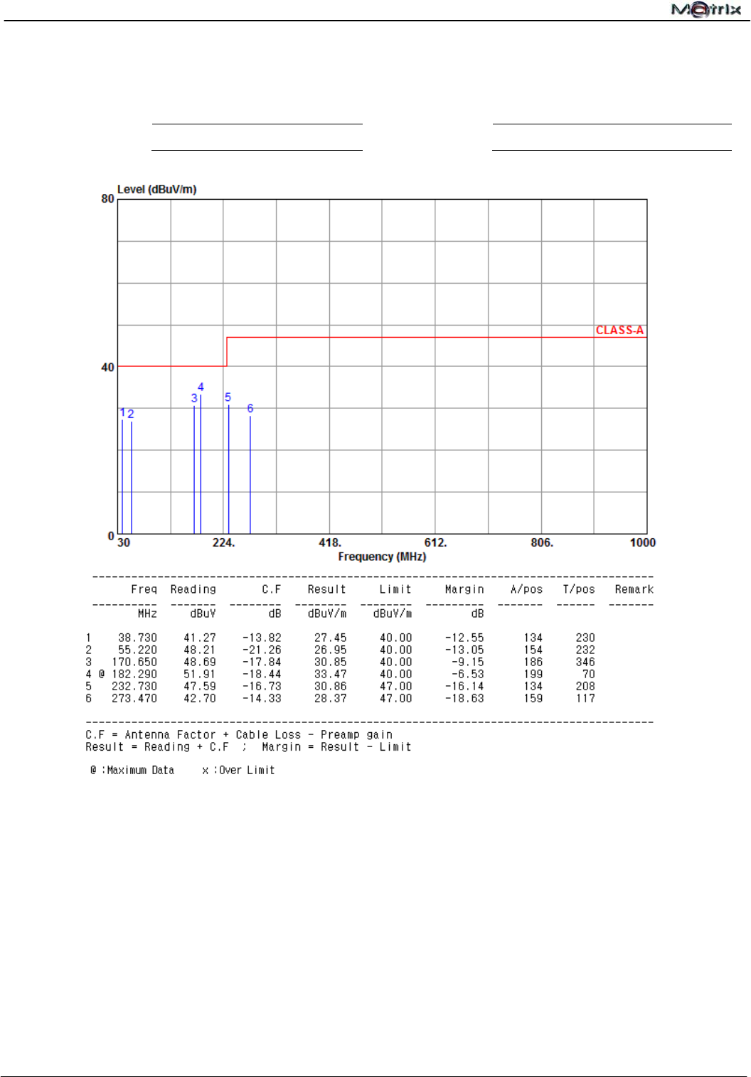
V: 182.290MHz, 51.91dBuV, Margin-6.53 dB
Antenna Height 1.99 m, Turntable Angle 70°
EN55022
Class A
Radiated
Disturbance
Test
(Above 1GHz)
Pass
Highest Emission
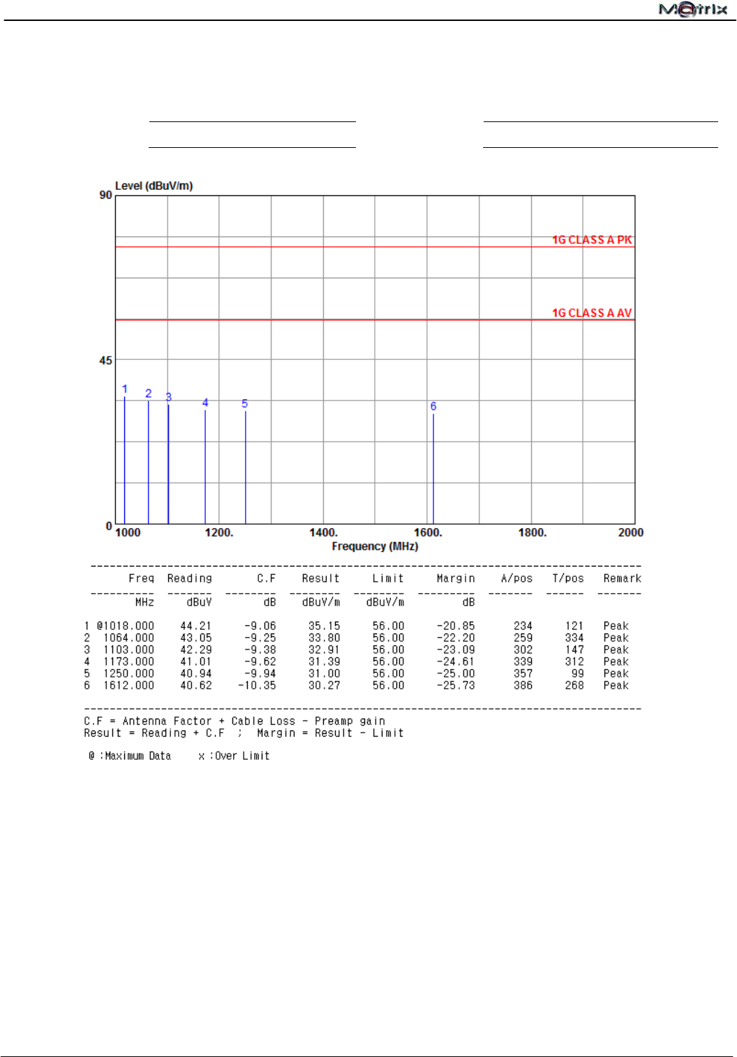
H: 1018.000MHz, 44.21dBuV, Margin-20.85dB
Antenna Height 2.34 m, Turntable Angle 121°
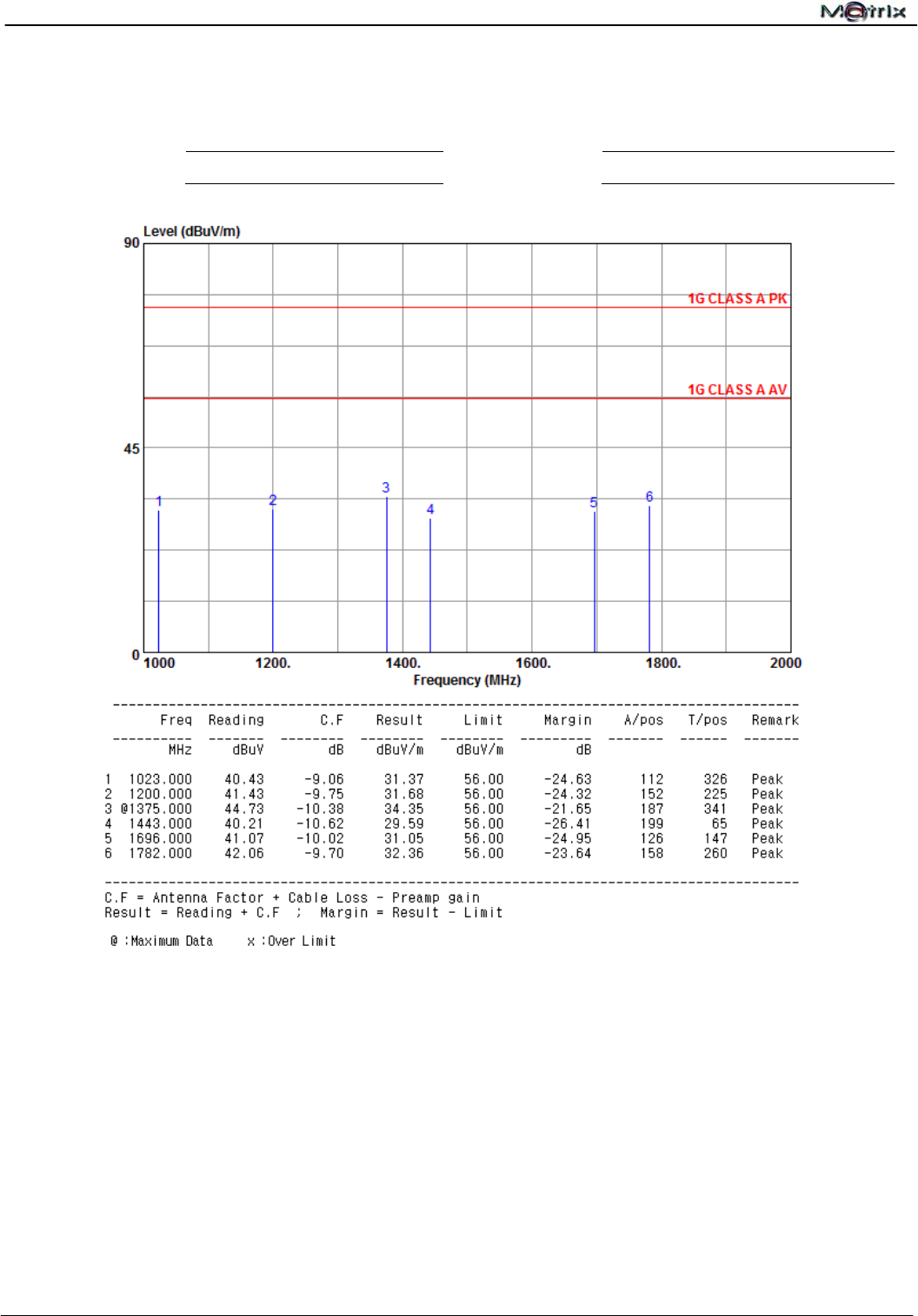
V: 1375.000MHz, 44.73dBuV, Margin-21.65 dB
Antenna Height 1.87 m, Turntable Angle 341°
EN61000-3-2 Harmonic Pass Refer to Page 30
EN61000-3-3 Flicker Pass Refer to Page 32

Report No.:U10040802E-A01
CE EMC Testing Report Page 7 of 59
Immunity
Test Standard Test Item Performance
Criteria
Observed
Result
Class
Test Result
IEC61000-4-2 Electrostatic Discharge B A Pass
IEC61000-4-3 Radiated Susceptibility A A Pass
IEC61000-4-4 Electrical Fast Transient B A Pass
IEC61000-4-5 Surge B A Pass
IEC61000-4-6 Conducted Susceptibility A A Pass
IEC61000-4-8 Magnetic Field A A Pass
Dips >95% B A
Dips 30% C A
IEC61000-4-11 Voltage Dips and Interruption Interruptions
>95% C B
Pass

Report No.:U10040802E-A01
CE EMC Testing Report Page 8 of 59
1 General Description
1.1 Description of EUT
Equipment Under Test : 1 Port PoE Injector
Model Number : PS-101
Series :
N/A
Applicant
Address of Applicant :
eten Technologies Inc.
2F, No.6, Lane 497, Zhongzheng Road, Xindian Dist., New Taipei City
231, Taiwan, R.O.C.
Manufacturer
Address of Manufacturer :
eten Technologies Inc.
2F, No.6, Lane 497, Zhongzheng Road, Xindian Dist., New Taipei City
231, Taiwan, R.O.C.
Power Supply : Input: 110~240Vac, 60 / 50Hz
Output: 48Vdc
Data Cable : N/A
Description of EUT :
Dimensions : 120 mm (L) X 50 mm (W) X 35 mm (H)
Weight : 145 g
Highest Frequency of the Internal Source : Above 108MHz
Position : Table-top / Floor-standing
Intended Function : The EUT is a 1 Port PoE Injector.

Report No.:U10040802E-A01
CE EMC Testing Report Page 9 of 59
1.2 Test Instruments
Instruments Used for Emission Measurement
Note: The instruments listed above are within their calibration period of 1 year.
Instrument Manufacturer Model Serial No. Calibration
Date Application
L.I.S.N. Mess Tec NNB-2/16Z 03/1006 2013-05-12 Conducted Emission
L.I.S.N. EMCIS LN2-16 LN04023 2013-02-08 Conducted Emission
Pulse Limiter Mess Tec PL10 N/A 2013-12-16 Conducted Emission
RF Cable N/A N/A N/A 2013-05-11 Conducted Emission
EMI Receiver R&S ESCI 100615 2013-03-03 Conducted Emission
Radiated Emission
Bilog Antenna Teseq GmbH CBL6111D 25769
2013-03-03 Radiated Emission
Pre-Amplifier Schaffner CPA9231A N/A 2013-07-20 Radiated Emission
Spectrum Analyzer HP 8595E 3829A03763 2013-07-19 Radiated Emission
Spectrum Analyzer R & S FSL6 100564 2013-12-05 Radiated Emission
RF Cable MIYAZAKI 8D-F8 N/A 2013-07-20 Radiated Emission
Programmable AC
Source Chroma 6520 2048 2013-02-01 Harmonic, Flicker
Universal Power
Analyzer Chroma 6630 0597 2013-02-01 Harmonic, Flicker

Report No.:U10040802E-A01
CE EMC Testing Report Page 10 of 59
Instruments Used for Immunity Measurement
Note: The instruments listed above are within their calibration period of 1 year.
Instrument Manufacturer Model Serial No. Calibration
Date Application
ESD Simulator Noiseken TC-815R ESS0868491 2009-12-17 Electrostatic
Discharge
ESD Simulator Noiseken ESS-2002EX ESS0868406 2009-12-17 Electrostatic
Discharge
Antenna FRANKONIA BTA-H 030001H 2009-08-03 Radiated Immunity
Field Probe EMCO 7201 N/A 2009-10-21 Radiated Immunity
Power Amplifier IFI CMX50 N/A 2009-10-21 Radiated Immunity
Signal Generator R&S SML03 103396 2010-01-29 Radiated Immunity
CDN FRANKONIA CDN M2+M3 A3011037 2010-03-03
Conducted Immunity
CDN FRANKONIA CDN M2+M3 A3011134 2010-03-03 Conducted Immunity
C.I. Test System FRANKONIA CIT-10/75 102C3208 2009-12-03 Conducted Immunity
Power Attenuator FRANKONIA 75-A-FFN-06 0212 2009-12-03 Conducted Immunity
RF Cable N/A N/A N/A 2009-05-07 Conducted Immunity
Antenna EMC
PARTNER MF-1000-1 119 2009-11-04
Magnetic Field
Disturbance
Transient 2000 EMC
PARTNER TRA-2000 449 2009-11-05
Electrostatic
Discharge,
Fast Transient,
Surge,
Magnetic Field
Disturbance,
Dips & Interruptions

Report No.:U10040802E-A01
CE EMC Testing Report Page 11 of 59
1.3 Auxiliary Equipments
For Immunity test
Provided by Matrix Test Lab.
No. Equipment Model No. Serial No. EMC
Approved Brand Power Cord
1. PC No.1 HP Pavilion A1510TW CNX6290BWF FCC, BSMI HP Non-shielded, Detachable, 1.5m
2. PC No.2 HP Pavilion A1510TW CNX6290BXQ FCC, BSMI HP Non-shielded, Detachable, 1.5m
3. Monitor No. 3 SDM-HS75P 1500379 FCC BSMI SONY
VGA CABLE
Shielded, Detachable, 1.5m, With
Core
DVI CABLE
Shielded, Detachable, 1.5m, With
Core
4. Monitor No. 5 VS11868 QRA074526459
CE FCC
BSMI
VIEW
SONIC
VGA CABLE
Shielded, Detachable, 1.8m, With
Core
DVI CABLE
Shielded, Detachable, 1.8m, With
Core
5. PS2 Key Board No. 2 Y-SU61 BT911DG4374 CE, FCC LOGITECH
PS2 CABLE
Non-shielded, Un-detachable, 1.7m,
Without Core
6. PS2 Key Board No. 5 Y-SU61 BT911DG4375 CE, FCC LOGITECH
PS2 CABLE
Non-shielded, Un-detachable, 1.7m,
Without Core
7. PS2 Mouse No. 2 M-SBF96 HC9070E036B CE FCC LOGITECH
PS2 CABLE
Non-shielded, Un-detachable, 1.8m,
Without Core
8. PS2 Mouse No. 6 M-SBF96 HC9070E0343 CE, FCC LOGITECH
PS2 CABLE
Non-shielded, Un-detachable, 1.8m,
Without Core
9. Printer No. 1 EPSON STYLUS C61 EK5Y014949 3912E328 EPSON PRINTER CABLE
Non-shielded, Detachable, 1.8M
10. Modem No. 1 1456VQE-C 1234A36998 3882B582 LEMEL RS-232 CABLE
Non-shielded, Detachable, 3M
11. Load 14Ω N/A N/A N/A N/A N/A
For Emission test
Provided by Matrix Test Lab.
No. Equipment Model No. Serial No. EMC
Approved Brand Power Cord
12. Notebook N61J N61JV-021A520M
CE,FCC,
C-TICK
N13219,
BSMI
R31018
ASUS
Adapter to Notebook
Unshielded*1.8m
AC to Adapter Unshielded*1.8m
13. Load 29Ω N/A N/A N/A N/A N/A
For Emission test
Provided by Manufacturer.
No. Equipment Model No. Serial No. EMC
Approved Brand Power Cord
14. Splitter PD-2024 N/A
N/A N/A N/A
Report No.:U10040802E-A01
CE EMC Testing Report Page 12 of 59
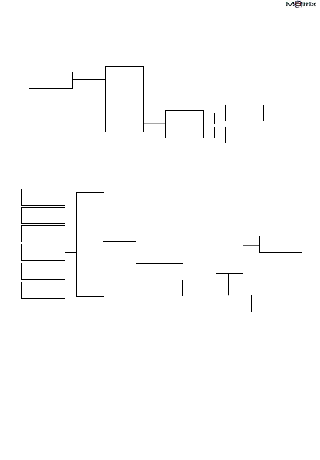
1.4 Block Diagram
1.5 Identifying the Final Test Mode ( Worst Case )
1. Operation Mode
Note: After pre-test, we identified that the Operation Mode (the worst case) was most likely to cause
maximum disturbance and most likely to be susceptible to disturbance. Therefore, the Final EMC
Assessment was performed for the worst case.
1.6 Final Test Mode
Operation Mode
1.7 Condition of Power Supply
AC 230V, 50Hz
LAN
LAN
LAN
Internet
EUT
AC Power
Notebook
Emission Test
EUT
Load 29Ω
Immunity test
PC
Splitter
(Provided by the
Manufacturer)
EUT
Monitor
PS2 K/B
PS2 Mouse
Printer
Modem
AC Power
AC Power
PC System
Load 14Ω
LAN
LAN
LAN

Report No.:U10040802E-A01
CE EMC Testing Report Page 13 of 59
1.8 EUT Configuration
1. Setup the EUT as shown in Sec.1.4 Block Diagram.
2. Turn on the power of all equipments.
3. Activate the selected Final Test Mode.
1.9 Immunity Performance Classification
Class Class Criterion
A
The equipment shall continue to operate as intended without operator intervention. No
degradation of performance or loss of function is allowed below a performance level
specified by the manufacturer when the equipment is used as intended.
B
After the test, the equipment shall continue to operate as intended without operator
intervention.
C
Lost of function is allowed, provided the function is self-recoverable, or can be restored
by the operation of the user in accordance with the manufacturer’s instructions.
1.10 Test Facility
Site Description : All tests are completed by Matrix Test Laboratory. Radiated emission
is performed at HongAn’s open-site.
Name of Firm : Matrix Test Laboratory
Site Location : 2F, No.146, Jian Yi Rd., Chung-Ho Dist., New Taipei City, Taiwan,
R.O.C.
1.10.1 Test Methodology
All Emission Tests were performed according to the procedures specified in EN 55022. Radiated
Emission Test was performed at 10 m distance from antenna to EUT. All Immunity Tests were
performed according to the procedures specified in EN 55024.
Report No.:U10040802E-A01
CE EMC Testing Report Page 14 of 59
2 Conducted Emission Test(at Mains Terminal)
2.1 Test Instruments
Refer to Sec. 1.2 Test Instruments.
2.2 Test Arrangement and Procedure
Table-top Equipment
- The EUT was placed on a non-conductive table which was 80 cm above the horizontal coupling
plane. The rear of the EUT was 40 cm from the vertical coupling plane.
- The excess interface cables were folded at the cable center into a bundle no longer than 40 cm, so
that the bundles were on the table.
- The EUT was connected to the main power through a L.I.S.N. This set up provided 50 ohm / 50
H coupling impedance for the measuring equipment.
- All auxiliary equipment received power from a second L.I.S.N.
- The conducted emissions were measured between the Line Phase and the PE ground and
between the Neutral Phase and the PE ground using an EMI Receiver.
- The values were recorded.

Report No.:U10040802E-A01
CE EMC Testing Report Page 15 of 59
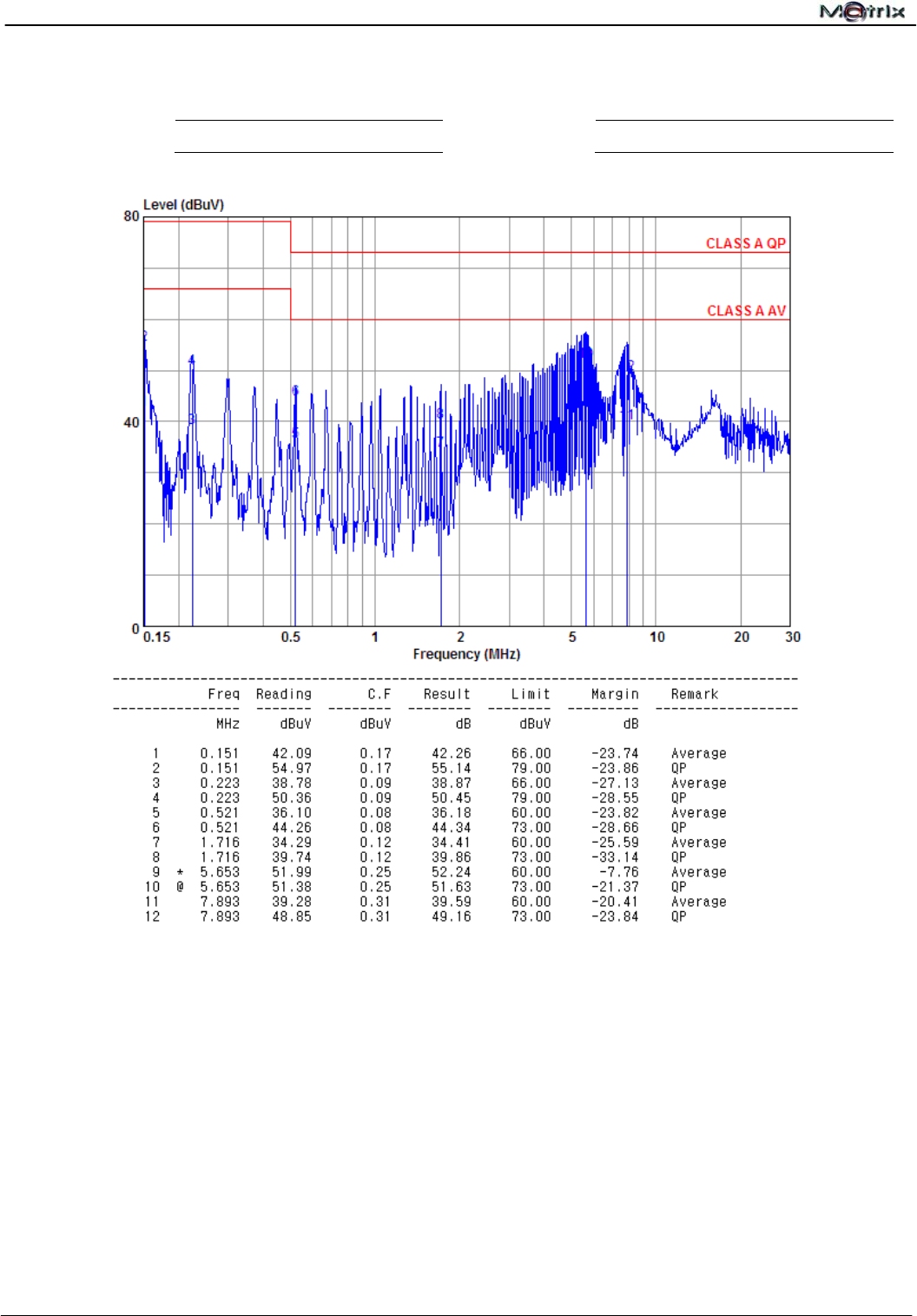
2.3 Conducted Limit
EN 55022
Class A Class B
Frequency (MHz)
Q.P. (Quasi-Peak) A.V. (Average) Q.P. (Quasi-Peak) A.V. (Average)
0.15 ~ 0.50 79 66 66 to 56 56 to 46
0.50 ~ 5.0 73 60 56 46
5.0 ~ 30 73 60 60 50
The EMI Receiver bandwidth was set at 9 kHz.
2.4 Test Result
PASS
The final test data are shown on the following page(s).
Report No.:U10040802E-A01
CE EMC Testing Report Page 16 of 59
Conducted Emission Test Data
Test Date : 2013-12-18 Power Line : Line
Temperature :
22.7℃ Humidity :
51%
Remark:All readings are Quasi-Peak and Average values.
Report No.:U10040802E-A01
CE EMC Testing Report Page 17 of 59
Conducted Emission Test Data
Test Date : 2013-12-18 Power Line : Neutral
Temperature :
22.7℃ Humidity :
51%
Remark:All readings are Quasi-Peak and Average values.

Report No.:U10040802E-A01
CE EMC Testing Report Page 18 of 59
3 Conducted Disturbance Test (at Telecommunication Ports)
3.1 Test Instruments
Refer to Sec. 1.2 Test Instruments.
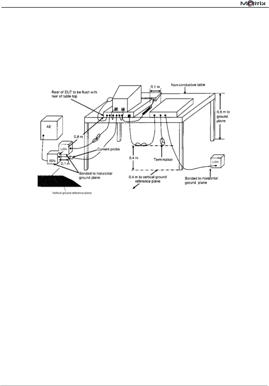
3.2 Test Arrangement and Procedure
Table-top Equipment
- The EUT was placed 0.4 meters from the horizontal ground plane with EUT being connected to
the power mains through a line impedance stabilization network(LISN). All other support
equipments powered from additional LISN(s). The LISN provide 50 Ohm/50H of coupling
impedance for the measuring instrument.
- Interconnecting cables that hang closer than 40cm to the ground plane shall be folded back and
forth in the center forming a bundle no longer than 40cm.
- I/O cables that are not connected to a peripheral shall be bundled in the center. The end of the
cable may be terminated, if required, using the correct terminating impedance. The overall length
shall not exceed 1m.
- ISN at least 80cm from nearest part of EUT chassis.
- The communication function of EUT was executed and ISN was connected between EUT and
associated equipment and the ISN was connected directly to reference ground plane.

Report No.:U10040802E-A01
CE EMC Testing Report Page 19 of 59
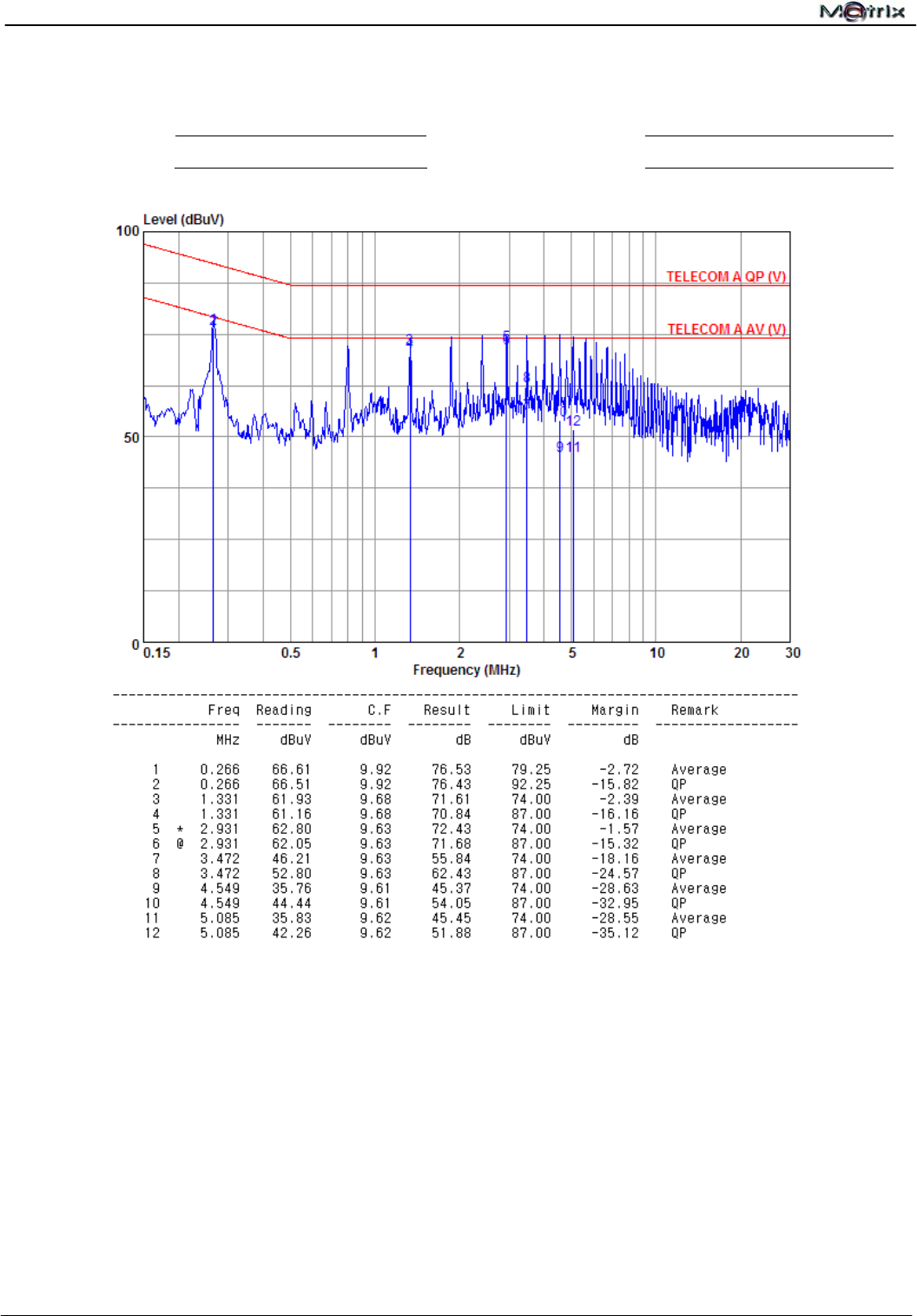
3.3 Conducted Limit
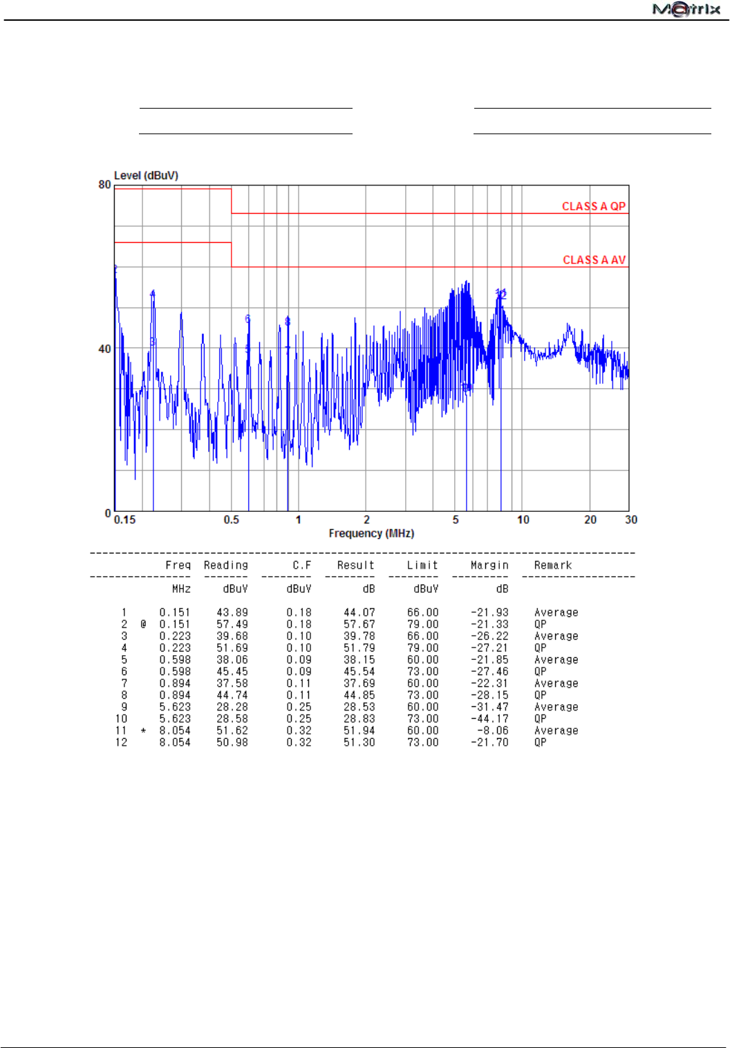
Limits of conducted common mode (asymmetric mode) disturbance at telecommunication ports in
the frequency range 0.15MHz to 30MHz for class A equipment.
Voltage Limits dB(V) Current Limits dB(A)
Frequency (MHz)
Q.P. (Quasi-Peak) A.V. (Average) Q.P. (Quasi-Peak) A.V. (Average)
0.15 ~ 0.5 97 to 87 84 to 74 53 to 43 40 to 30
0.5 ~ 30 87 74 43 30
NOTE1: The limits decrease linearly with the logarithm of the frequency in the range 0.15MHz to
0.5MHz.
NOTE2: The current and voltage disturbance limits are derived for use with an impedance
stabilization network (ISN) which presents a common mode (asymmetric mode) impedance of 150
Ω to the telecommunication port under test (conversion factor is 20 log10 150/I=44dB)
Limits of conducted common mode (asymmetric mode) disturbance at telecommunication ports in
the frequency range 0.15MHz to 30MHz for class B equipment.
Voltage Limits dB(V) Current Limits dB(A)
Frequency (MHz)
Q.P. (Quasi-Peak) A.V. (Average) Q.P. (Quasi-Peak) A.V. (Average)
0.15 ~ 0.5 84 to 74 74 to 64 40 to 30 30 to 20
0.5 ~ 30 74 64 30 20
NOTE1: The limits decrease linearly with the logarithm of the frequency in the range 0.15MHz to
0.5MHz.
NOTE2: The current and voltage disturbance limits are derived for use with an impedance
stabilization network (ISN) which presents a common mode (asymmetric mode) impedance of 150
Ω to the telecommunication port under test (conversion factor is 20 log10 150/I=44dB)
3.4 Test Result
PASS
The final test data are shown on the following page(s).
Report No.:U10040802E-A01
CE EMC Testing Report Page 20 of 59
Conducted Disturbance Test Data
Test Date : 2013-12-18 Measurement Method : Voltage
Temperature :
22.7℃ Humidity : 51%
Remark:All readings are Quasi-Peak and Average values.
Report No.:U10040802E-A01
CE EMC Testing Report Page 21 of 59
4 Radiated Disturbance Test – Below 1 GHz
4.1 Test Instruments
Refer to Sec. 1.3 Test Instruments.
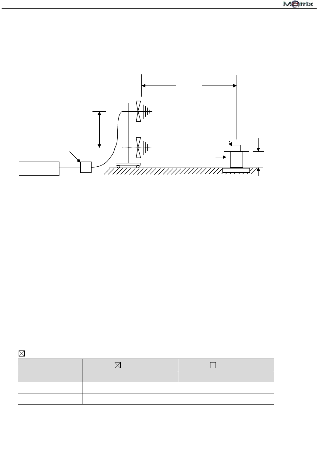
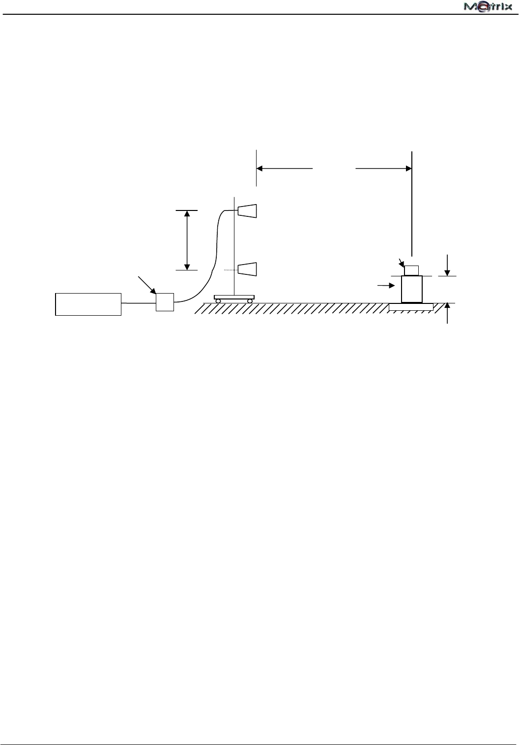
4.2 Test Arrangement and Procedure
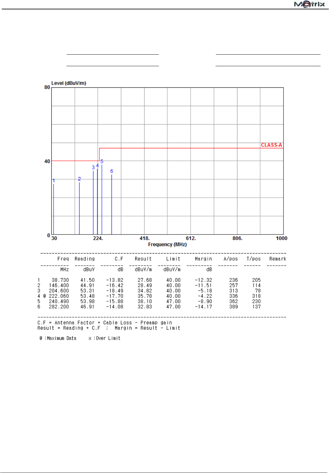
4.3 Test Limit
EN 55022
Class A Class B
Frequency (MHz)
Quasi-Peak (dBuV/m) Quasi-Peak (dBuV/m)
30 ~ 230 40.0 30.0
230 ~ 1000 47.0 37.0
The EMI test receiver bandwidth was set at 120 kHz.
4.4 Test Result
PASS
The final test data are shown on the following page(s).
EUT
Pre-Amplifier
Turn Table
10 m
1~ 4 m
Test Receiver
80 cm
Table-top Equipment
- The EUT was place on a non-conductive turntable which was 80 cm above the
horizontal ground plane. The EUT was set 10 m away from the receiving antenna that
was mounted on a non-conductive mast.
- Main cables draped to the ground plane and were routed to the mains power outlet.
The mains power outlet was bonded to and did not protrude above the ground plane.
- The antenna was adjusted between 1 m and 4 m in height above the ground plane and
the Antenna-to-EUT azimuth was also varied during the measurements to find the top
6 maximum meter readings within the frequency range limit as indicated in Sec 3.3.
- The radiated emissions were measured when the Antenna-to-EUT polarization was set
horizontally and vertically.
- The values were reco
r
ded.
Report No.:U10040802E-A01
CE EMC Testing Report Page 22 of 59
Radiated Emission Test Data
Test Date : 2013-12-18 Polarization : Horizontal
Temperature :
22.7℃ Humidity :
51%
Remark:All readings are Quasi-Peak values.
Report No.:U10040802E-A01
CE EMC Testing Report Page 23 of 59
Radiated Emission Test Data
Test Date : 2013-12-18 Polarization : Vertical
Temperature :
22.7℃ Humidity :
51%
Remark:All readings are Quasi-Peak values.
Report No.:U10040802E-A01
CE EMC Testing Report Page 24 of 59
5 Radiated Disturbance Test – Above 1 GHz
5.1 Test Instruments
Refer to Sec. 1.3 Test Instruments.
5.2 Test Configuration and Procedure
Table-top Equipment
- The EUT was place on a non-conductive turntable which was 80cm above the horizontal
ground plane. The EUT was set 3m away from the receiving antenna that was mounted on
a non-conductive mast.
- Main cables draped to the ground plane and were routed to the mains power outlet. The
mains power outlet was bonded to and did not protrude above the ground plane.
- The antenna was adjusted between 1m and 4m in height above the ground plane and the
Antenna-to-EUT azimuth was also varied during the measurements to find the top 6
maximum meter readings within the frequency range limit as indicated in Sec 4.3.
- The radiated emissions were measured when the Antenna-to-EUT polarization was set
horizontally and vertically.
- The values were recorded.
Turn Table
EUT
Pre-Amplifier
3 m
1~ 4 m
Test Receiver
80 cm

Report No.:U10040802E-A01
CE EMC Testing Report Page 25 of 59
5.3 Test Limit
EN55022 Class A ITE at a measurement distance of 3m
Frequency
GHz
Average limit
dB(µV/m)
Peak limit
dB(µV/m)
1 to 3 56 76
3 to 6 60 80
NOTE The lower limit applies at the transition frequency.
EN55022 Class B ITE at a measurement distance of 3m
Frequency
GHz
Average limit
dB(µV/m)
Peak limit
dB(µV/m)
1 to 3 50 70
3 to 6 54 74
NOTE The lower limit applies at the transition frequency.
5.4 Test Result
PASS
The final tests data are shown on the following page(s).
Report No.:U10040802E-A01
CE EMC Testing Report Page 26 of 59
Radiated Emission Test Data
Test Date : 2013-12-18 Polarization : Horizontal
Temperature :
22.7℃ Humidity :
51%
Remark:All readings are Peak values. None of the peak value reading exceeds the A.V. limit. Hence, A.V.
reading was not measured.
Report No.:U10040802E-A01
CE EMC Testing Report Page 27 of 59
Radiated Emission Test Data
Test Date : 2012-12-18 Polarization : Vertical
Temperature :
22.7℃ Humidity :
51%
Remark:All readings are Peak values. None of the peak value reading exceeds the A.V. limit. Hence, A.V.
reading was not measured.
Report No.:U10040802E-A01
CE EMC Testing Report Page 28 of 59
6 Harmonic Current Emission Measurement
6.1 Test Instruments
Refer to Sec. 1.2 Test Instruments.
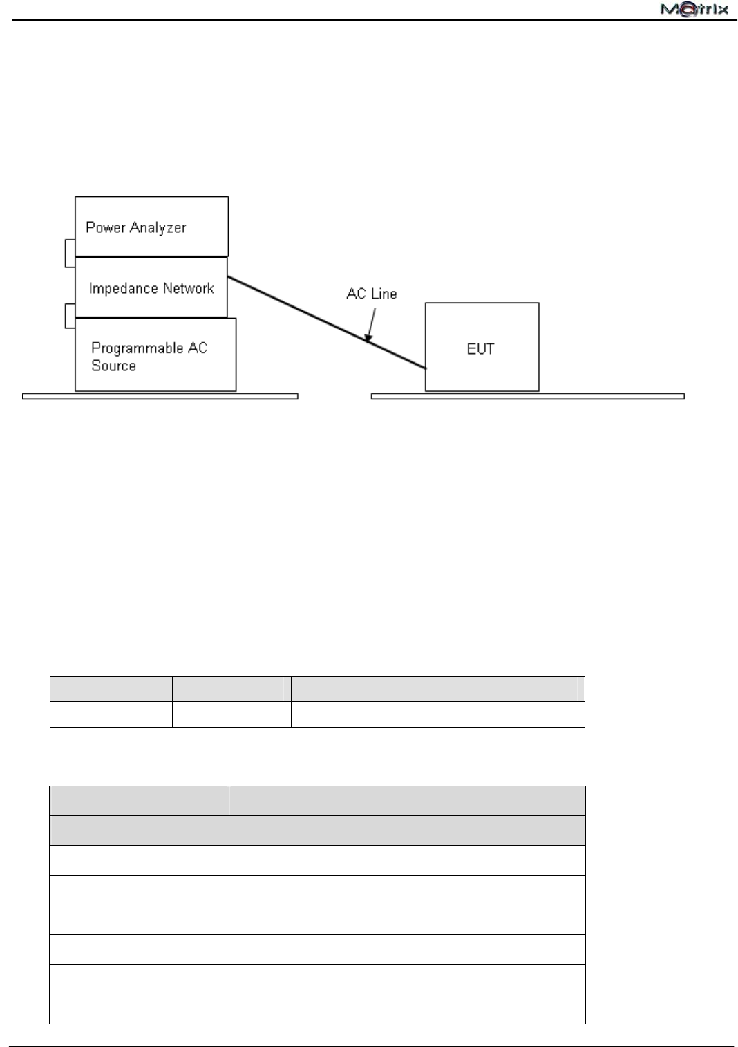
6.2 Test Configuration and Procedure
6.3 EUT Operation Condition
Environment Condition
Temperature Humidity Atmospheric Pressure
22.7℃ 51%RH 1019mbar
6.4 Test Limit
Class A Equipment
Harmonic Order (n) Maximum permissible harmonic current (A)
Odd harmonics
3 2.30
5 1.14
7 0.77
9 0.40
11 0.33
13 0.21
- The EUT was set in series with the Power Analyzer through an Impedance Network for
the measurement of harmonic currents.
- The supply voltage and frequency setting on the Programmable AC Source was
programmed as the rated voltage and frequency of the EUT.
- Classify the EUT class in accordance with the IEC61000-3-2 for the purpose of harmonic
current limitation. The measurement was automatically performed by test software. The
test result was collected and anal
y
zed b
y
the com
p
uter.

Report No.:U10040802E-A01
CE EMC Testing Report Page 29 of 59
15 ≤ n ≤ 39 0.15 * 15 / n
Even harmonics
2 1.08
4 0.43
6 0.30
8 ≤ n ≤ 40 0.23 * 8 / n
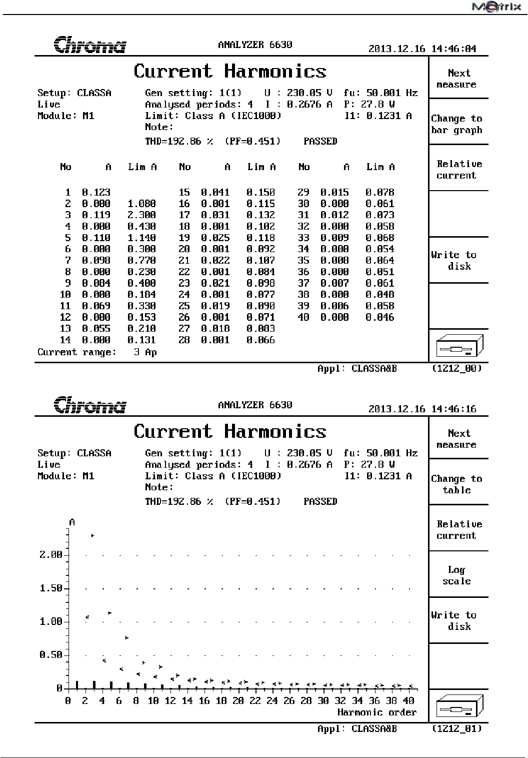
6.5 Test Result
PASS
The measured result is shown on the following page(s).
Report No.:U10040802E-A01
CE EMC Testing Report Page 30 of 59
Note: The EUT power level is below 75watts therefore has no defined limits.
Report No.:U10040802E-A01
CE EMC Testing Report Page 31 of 59
7 Voltage Fluctuations and Flicker Measurement
7.1 Test Instruments
Refer to Sec. 1.2 Test Instruments.
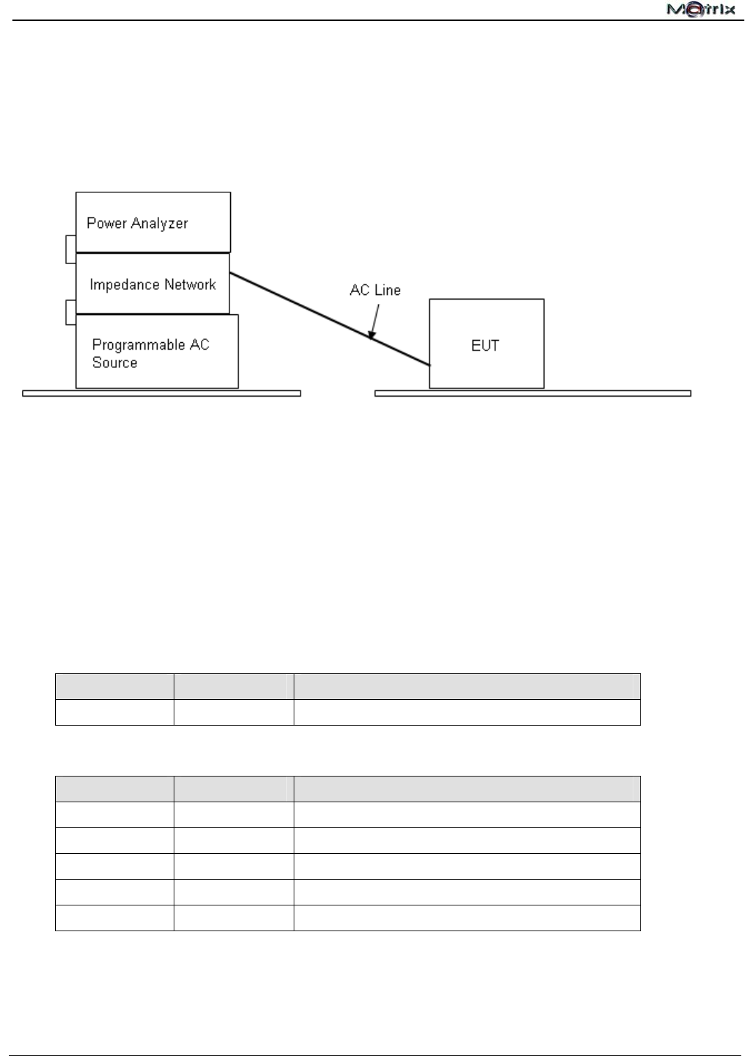
7.2 Test Configuration and Procedure
7.3 EUT Operation Condition
Environment Condition
Temperature Humidity Atmospheric Pressure
22.7℃ 51%RH 1019mbar
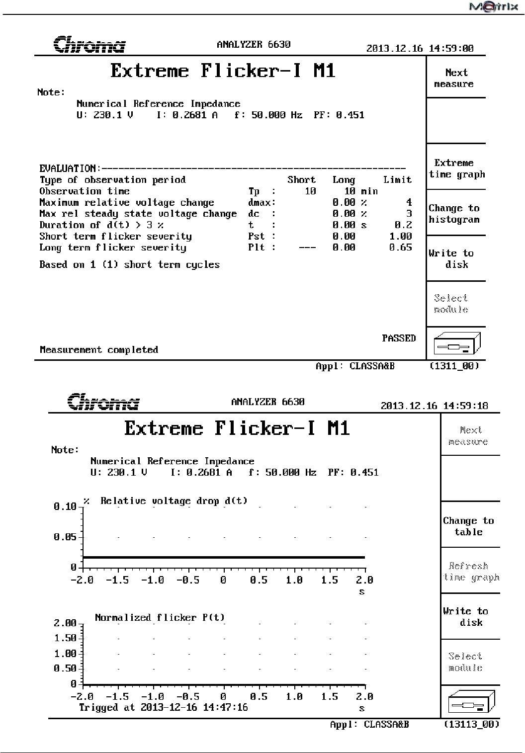
7.4 Test Limit
Test Item Limit Remark
Pst 1.0 Pst means short-term flicker indicator. Tp=10 min
Plt 0.65 Plt means long-term flicker indicator. Tp=2 hrs
dt (%) 3.3 For more than 500ms
dmax (%) 4 dmax means relative maximum voltage change.
dc (%) 3.3 dc means relative steady-state voltage change.
7.5 Test Result
PASS
The measured result is shown on the following page(s).
- The EUT was set in series with the Power Analyzer through an Impedance Network for the
measurement of Flicker Voltage.
- The supply voltage and frequency setting on the Programmable AC Source was programmed
as the rated voltage and frequency of the EUT.
- The measurement was automatically performed by test software. The test result was collected
and analyzed by the computer.
Report No.:U10040802E-A01
CE EMC Testing Report Page 32 of 59
Report No.:U10040802E-A01
CE EMC Testing Report Page 33 of 59
8 Electrostatic Discharge Immunity Test
8.1 Test Instruments
Refer to Sec. 1.2 Test Instruments.
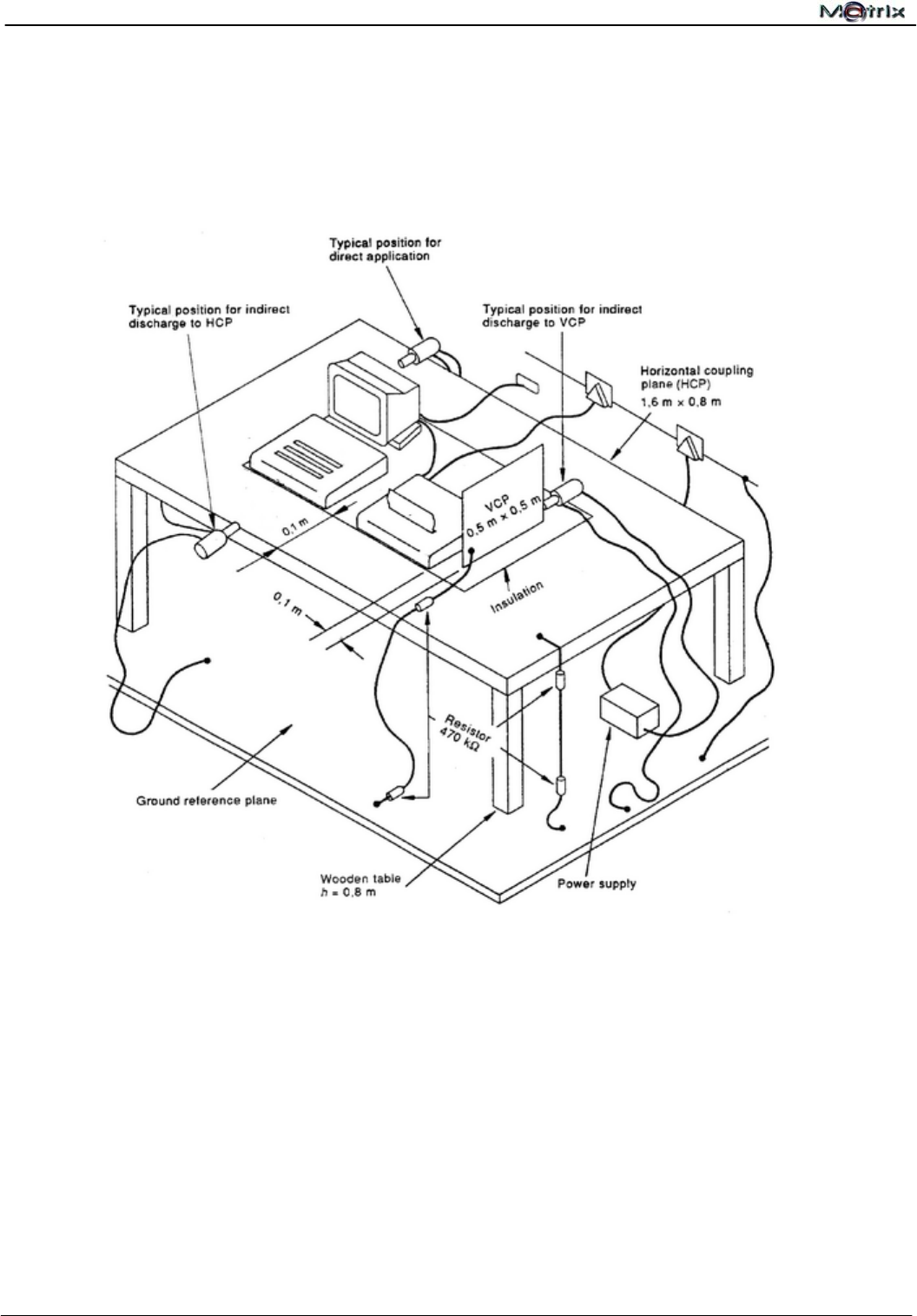
8.2 Test Configuration and Procedure
Table-top Equipment
- The EUT was located on a 0.8 m high wooden table standing on the ground reference
plane with a 1.6 * 0.8 m horizontal coupling plane on the top. The EUT and cables was
isolated from the coupling plane by an insulating support 0.5 mm thick.
- In Contact Discharge, the EUT was exposed to minimum 200 discharges, 100 each at
negative and positive polarity on the selected test points ( the selected test points were
marked with red labels on the EUT )
- In Air Discharge, the EUT exposed to minimum of 10 single discharges on the selected
test points.
- The result was observed and analyzed.

Report No.:U10040802E-A01
CE EMC Testing Report Page 34 of 59
8.3 Test Result
8.3.1 Environment Condition
8.3.2 Observation of Direct Discharge
Test Points: 1. Junction of Case. 2. LED Indicator. 3. AC Jack. 4. LAN Jacks.
Test Specifications Performance
Type of
Discharge
Test
Level Polarity Test
Point
Number of
Discharge
Required by
EN55024
Observed
Result Verdict
Air
Discharge
2,4,8
(kV)
± 1~4 20/ per
point B A Pass
Contact
Discharge
2,4
(kV)
± 4 50/ per
point B A Pass
Remarks 1. No temporary degradation or loss of function has been observed throughout
the entire time interval of air discharge.
2. No temporary degradation or loss of function has been observed throughout
the entire time interval of contact discharge.
8.3.3 Observation of Indirect Discharge
Test Points: 1. Front Side. 2. Rear Side. 3. Left Side. 4. Right Side.
Test Specifications Performance
Type of
Discharge
Test
Level Polarity Te s t
Point
Number of
Discharge
Required by
EN55024
Observed
Result Verdict
HCP
Application
2,4
(kV)
± 1~4 50/ per
point B A Pass
VCP
Application
2,4
(kV)
± 1~4 50/ per
point B A Pass
Remarks 1. No temporary degradation or loss of function has been observed throughout
the entire time interval of HCP application.
2. No temporary degradation or loss of function has been observed throughout
the entire time interval of VCP application.
PASS
The test result shows that the EUT is in compliance with the test performance criteria specified
in EN 55024.
Temperature Humidity Atmospheric Pressure
21℃ 48%RH 1022.1mbar
Report No.:U10040802E-A01
CE EMC Testing Report Page 35 of 59
9 Radio-frequency, Electromagnetic Field Immunity Test
9.1 Test Instruments
Refer to Sec. 1.2 Test Instruments.
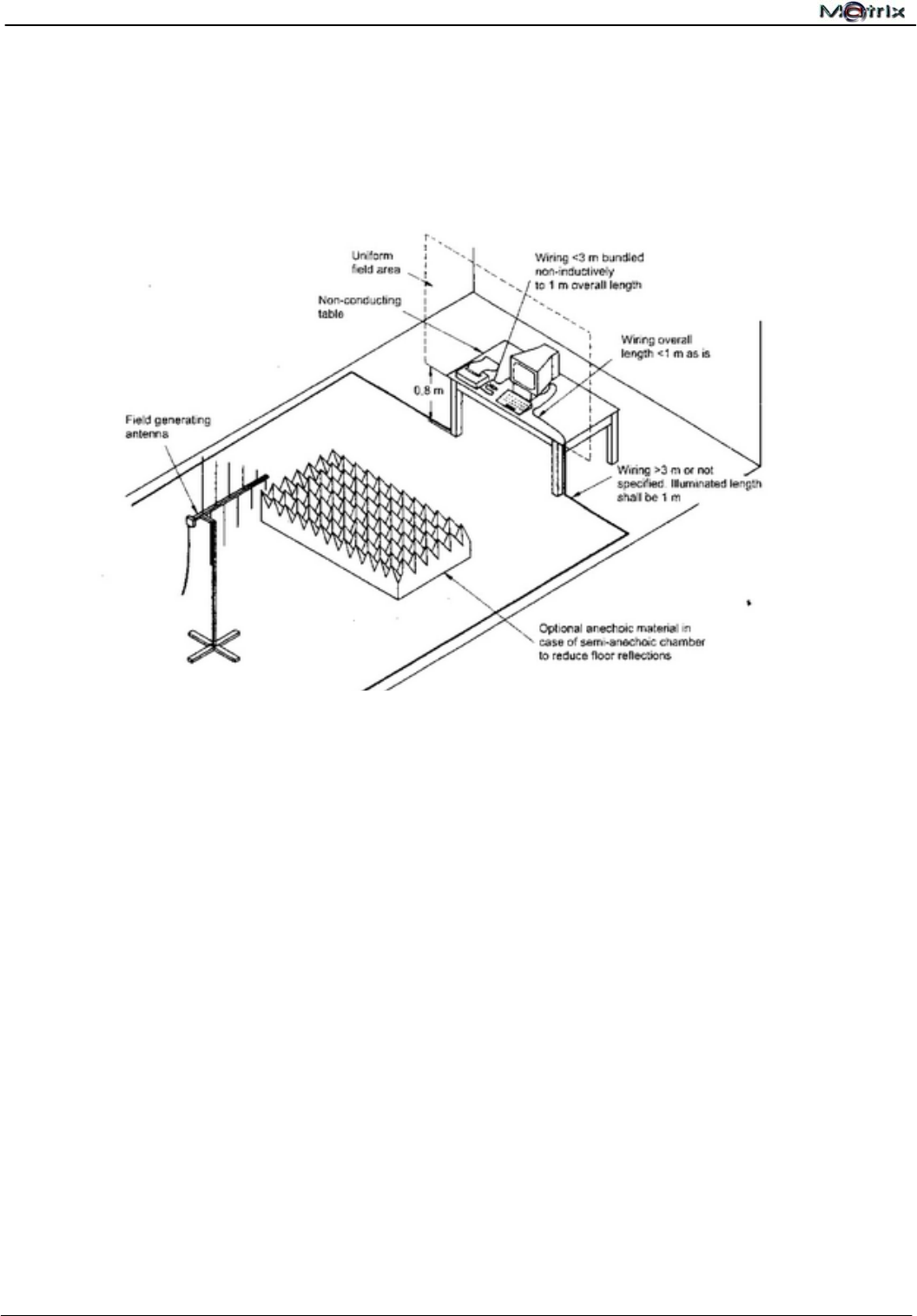
9.2 Test Configuration and Procedure
Table-top Equipment
- The field calibration was executed to create a uniform field area (UFA), 3 m away from the
antenna, to ensure the validity of the test results.
- The EUT was placed on a non-conductive table 0.8 m high in the UFA.
- The EUT was then connected to power and signal wires according to relevant installation
instruction.
- The EUT was positioned so that the four sides of the EUT were exposed to the
electromagnetic field in sequence. In each position, the performance of the EUT was
investigated and monitored by a CCD camera..

Report No.:U10040802E-A01
CE EMC Testing Report Page 36 of 59
9.3 Test Result
9.3.1 Environment Condition
Temperature Humidity Atmospheric Pressure
21℃ 48%RH 1022.1mbar
9.3.2 Observation of Test
Test Specifications Performance
Type of
Modulation
Field
Strength
Frequency
Range Modulation Required by
EN55024
Observed
Result Verdict
Amplitude
Modulation 3V/m 80 to
1000MHz
80%, 1KHz,
sinusoidal A A Pass
Remark No temporary degradation or loss of function has been observed throughout the
entire test.
PASS
The test result shows that the EUT is in compliance with the test performance criteria
specified in EN 55024.
Report No.:U10040802E-A01
CE EMC Testing Report Page 37 of 59
10 Electrical Fast Transient Test
10.1 Test Instrument
Refer to Sec. 1.2 Test Instruments.
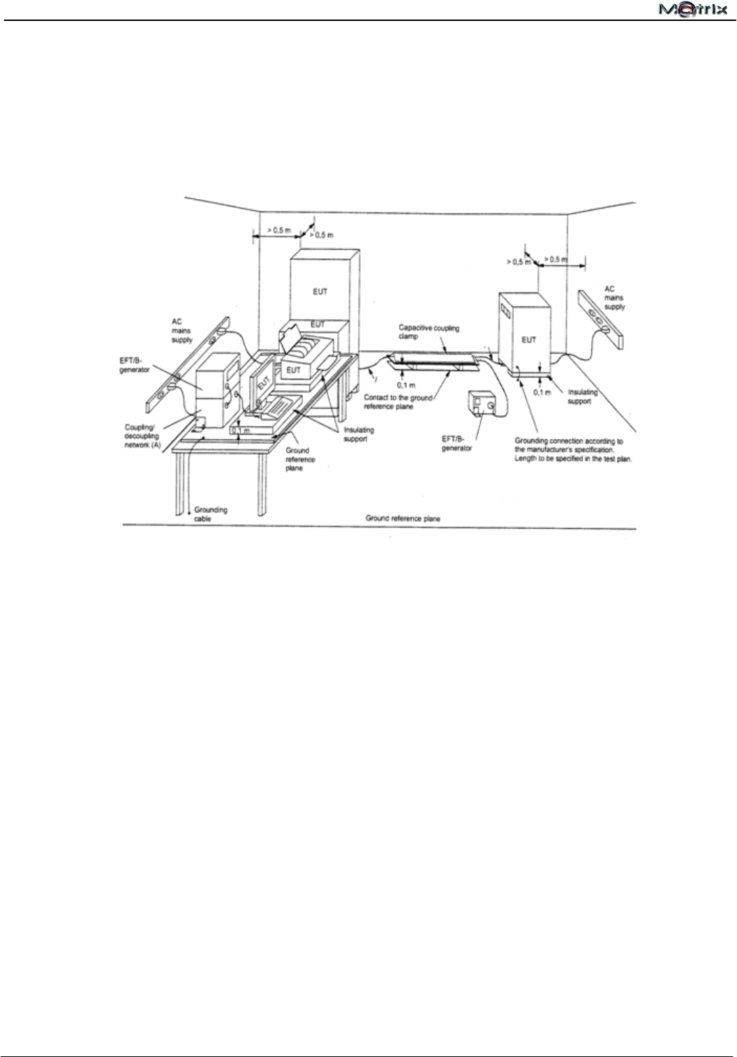
10.2 Test Configuration and Procedure
Table-top Equipment
- The EUT was placed on a table of 0.8 m height above the 1 * 1 m metallic ground reference
plane, which projected beyond the EUT by at least 0.1 m on all sides.
- The ground plane was connected to the protective earth.
- The distance between the EUT and all other conductive structures, except the ground plane
beneath the EUT was more than 0.5 m.
- The length of the signal and power lies between the coupling device and the EUT was 0.5 m.
- All cables to the EUT were placed on the insulation support 0.1 m above the ground reference
plane.
- The EUT was connected to the power mains through a coupling device that directly coupled
the EFT interference signal. Each of the Line, Neutral and Protective Earth conductors was
injected with burst for 1 minute. The test time was broken down into six 10 s bursts separated
by a 10 s pause for avoiding synchronization. Both voltage polarities were applied for each test
level.
- Operating condition was shown on the monitor and observed.

Report No.:U10040802E-A01
CE EMC Testing Report Page 38 of 59
10.3 Test Result
10.3.1 Environment Condition
10.3.2 Observation of Power Supply Port
Test Specifications
Coupling
Selection Voltage
(kV)
Test
Duration
(Sec)
Repetition
Rate
(kHz)
Tr/ Td
(nS)
Performance
Required by
EN 55024
Observed
Result Verdict
L ±1 60 5 5/50 B A Pass
N ±1 60 5 5/50 B A Pass
PE ±1 60 5 5/50 B A Pass
L + N ±1 60 5 5/50 B A Pass
L + PE ±1 60 5 5/50 B A Pass
N + PE ±1 60 5 5/50 B A Pass
L + N +PE ±1 60 5 5/50 B A Pass
Remark No temporary degradation or loss of function has been observed throughout the
entire test.
Note Phase Shifting:0º,90º,180º,270º,360º
10.3.3 Observation of I/O, communication ports (Applicable only to cable length >3m)
There was no I/O and communication cable longer than 3 meter; therefore, no test has been
required.
PASS
The test result shows that the EUT is in compliance with the test performance criteria
specified in EN 55024.
Temperature Humidity Atmospheric Pressure
21℃ 48%RH 1022.1mbar
Report No.:U10040802E-A01
CE EMC Testing Report Page 39 of 59
11 Surge Immunity Test
11.1 Test Instrument
Refer to Sec. 1.2 Test Instruments.
11.2 Test Configuration and Procedure
Metallic Ground Plane
EUT
TRANSIENT
2000(Surge)
Table-top Equipment
- The EUT was placed on a table of 0.8 m height above the 1 * 1 m metallic ground reference
plane, which projected beyond the EUT by at least 0.1 m on all sides.
- The ground plane was connected to the protective earth.
- The length of power cord between the coupling device and the EUT is less than 2 m (provided
by the manufacturer).
- The EUT was connected to the power mains through a coupling device that directly couples
the Surge interference signal. The surge noise was applied synchronized to the voltage phase
at the zero crossing and the peak value of the AC voltage wave (positive and negative).
- The surges were applied line to line and line(s) to earth. When testing line to earth the test
voltage was applied successively between each of the lines and earth. Steps up to the test
level specified increased the test voltage. All lower levels including the selected test level were
tested. The polarity of each surge level included positive and negative test pulses.
- Operating condition was shown on the monitor and observed.

Report No.:U10040802E-A01
CE EMC Testing Report Page 40 of 59
11.3 Test Result
11.3.1 Environment Condition
11.3.2 Observation of Power Supply Port
Test Specifications Performance
Coupling
Selection
Voltage
(kV)
Min. of Surge
at Each
Polarity
Repetition
Rate
(per min)
Required by
EN 55024
Observed
Result Verdict
L ►N ±0.5, 1 5 1 B A Pass
L ►PE ±0.5, 1,2 5 1 B A Pass
N ►PE ±0.5, 1,2 5 1 B A Pass
Remark No temporary degradation or loss of function has been observed throughout the
entire test.
11.3.3 Observation of other supply/ signal lines: (Applicable only to ports which according to the
manufacturer’s specification may connect directly to outdoor cables)
N/A
PASS
The test result shows that the EUT is in compliance with the test performance criteria
specified in EN 55024.
Temperature Humidity Atmospheric Pressure
21℃ 48%RH 1022.1mbar
Report No.:U10040802E-A01
CE EMC Testing Report Page 41 of 59
12 Radio-frequency, Conducted Disturbances Immunity Test
12.1 Test Instruments
Refer to Sec. 1.2 Test Instruments.
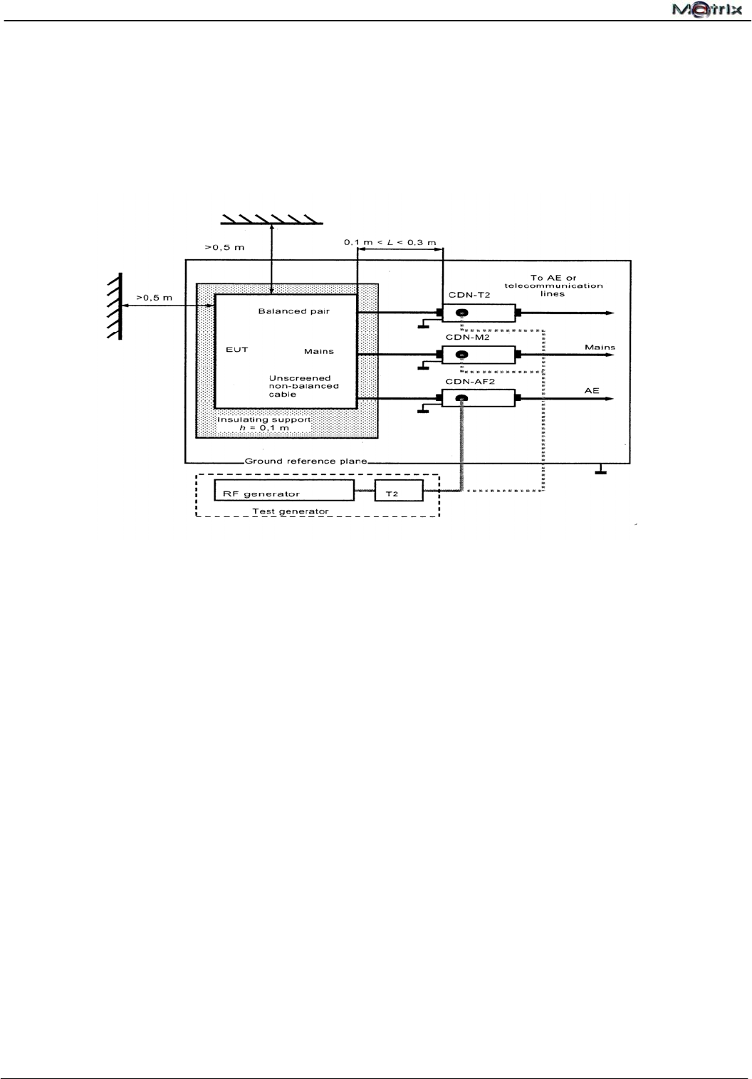
12.2 Test Configuration and Procedure
- The EUT was placed on an insulating support of 0.1 m height above a ground reference plane.
All cables exiting the EUT was supported at a height of 30 mm above the ground reference
plane.
- The EUT was connected to the power mains through a Coupling and Decoupling Networks
(CDN).
- The CDN was located 0.3 m from the EUT as indicated in the diagram above.
- The test was performed with the test generator connected to each of the CDN in turn while the
other non-excited RF input ports of the coupling devices were terminated by a 50 terminator.
- The conducted disturbance was applied on the EUT from 150 kHz to 80 MHz using the signal
levels established during the setting process. .
- Operating condition was shown on the monitor and observed.

Report No.:U10040802E-A01
CE EMC Testing Report Page 42 of 59
12.3 Test Result
12.3.1 Environment Condition
12.3.2 Observation of Test
12.3.3 Observation of I/O, communication ports (Applicable only to cable length >3m)
There was no I/O and communication cable longer than 3 meter; therefore, no test has been
required.
PASS
The test result shows that the EUT is in compliance with the test performance criteria
specified in EN 55024.
Temperature Humidity Atmospheric Pressure
21℃ 48%RH 1022.1mbar
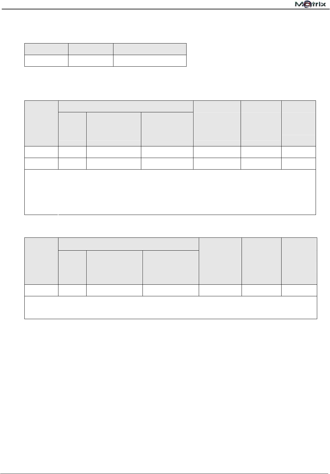
Test Specifications Performance
Type of
Modulation
Voltage Level
(emf) U0
Frequency
Range Modulation Required by
EN 55024
Observed
Result Verdict
Amplitude
Modulation 3V/ 130dBμV 0.15 to
80MHz
80%,
1kHz,
sinusoidal
A A Pass
Remark No temporary degradation or loss of function has been observed throughout the
entire test.
Note Phase Shifting:0º,90º,180º,270º,360º
Report No.:U10040802E-A01
CE EMC Testing Report Page 43 of 59
13 Power Frequency Magnetic Field Immunity Test
13.1 Test Instruments
Refer to Sec. 1.2 Test Instruments.
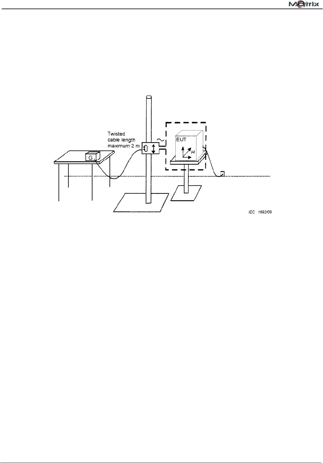
13.2 Test Configuration and Procedure
Table-top Equipment
- The EUT was placed on a non-magnetic metal ground plane of 0.25 mm thickness with the
interposition of a 0.1 m thickness insulating support. The ground plane was connected to the
protected earth.
- The EUT was placed at the center of the 1 * 1 m induction coil with the test generator placed
within 3 m distance.
- The test was operated by moving and shifting the induction coil to expose to the test field.
- The operation condition was observed and analyzed.
- The induction coil was then rotated by 90° to expose the EUT to the test field with different
orientations and the same procedure.

Report No.:U10040802E-A01
CE EMC Testing Report Page 44 of 59
13.3 Test Result
13.3.1 Environment Condition
Temperature Humidity Atmospheric Pressure
21℃ 48%RH 1022.1mbar
13.3.2 Observation of Test
Level (A/m) Frequency
(Hz)
Performance Required
by EN55024
Observed
Result Verdict
1 50 A A Pass
Remark No temporary degradation or loss of function has been observed
throughout the entire test.
PASS
The test result shows that the EUT is in compliance with the test performance criteria
specified in EN 55024.
Report No.:U10040802E-A01
CE EMC Testing Report Page 45 of 59
14 Voltage Dips, Short Interruptions Immunity Test
14.1 Test Instrument
Refer to Sec. 1.2 Test Instruments.
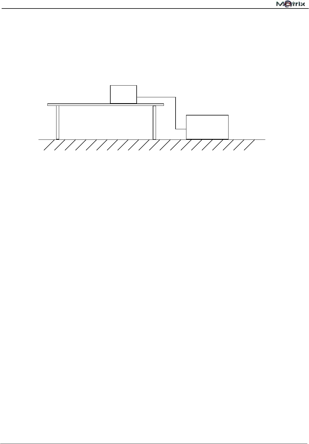
14.2 Test Configuration and Procedure
- The EUT was tested with (Ⅰ) >95% voltage dip of supplied voltage with a duration of 10 ms
(Ⅱ) 30% voltage dip of supplied voltage with duration 500 ms (Ⅲ) A 95% voltage interruption
of supplied voltage with duration of 5000 ms,
- For each selected combination of test level and duration with a sequence of three dips /
interruptions with intervals of 10 s.
- For Voltage Dips, changes in supply voltage occurred at zero crossings of the voltage.
- For Short Interruptions, changes in supply voltage also occurred at zero crossings of the
voltage.
- The performance of the EUT was monitored and recorded.
Metallic Ground Plane
EUT
TRANSIENT
2000(Dips)
Report No.:U10040802E-A01
CE EMC Testing Report Page 46 of 59
14.3 Test Result
14.3.1 Environment Condition
Temperature Humidity Atmospheric Pressure
21℃ 48%RH 1022.11mbar
14.3.2 Observation of Power Supply Port
Voltage Dips
Test Specifications Performance
Voltage
Reduction
(%)
Duration
Periods
No. of
Reductions
Interval between
Each Duration
(sec.)
Required by
EN 55024
Observed
Result Verdict
>95 0.5 3 ≥ 10 B A Pass
30 25 3 ≥ 10 C A Pass
1. No temporary degradation or loss of function has been observed throughout the
entire test.
Remarks
2. No temporary degradation or loss of function has been observed throughout the
entire test.
Voltage Interruptions
Test Specifications Performance
Voltage
Reduction
(%)
Duration
Periods No. of Reductions
Interval between
Each Duration
(sec.)
Required by
EN 55024
Observed
Result Verdict
>95 250 3 ≥ 10 C B Pass
Remark When testing Voltage Dip with 4% of the normal power supply voltage, the power
indicator went off. After testing, it self-recovered.
PASS
The test result shows that the EUT is in compliance with the test performance criteria
specified in EN 55024.
Report No.:U10040802E-A01
CE EMC Testing Report Page 47 of 59
15 Photographs of Test
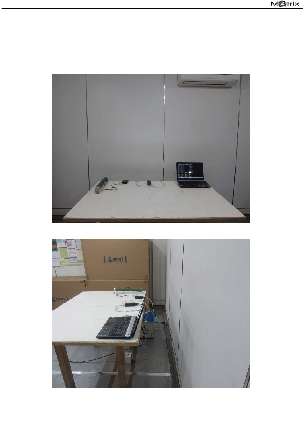
15.1 Conducted Disturbance Test(at Mains Terminals)
Front View
Rear View
Report No.:U10040802E-A01
CE EMC Testing Report Page 48 of 59
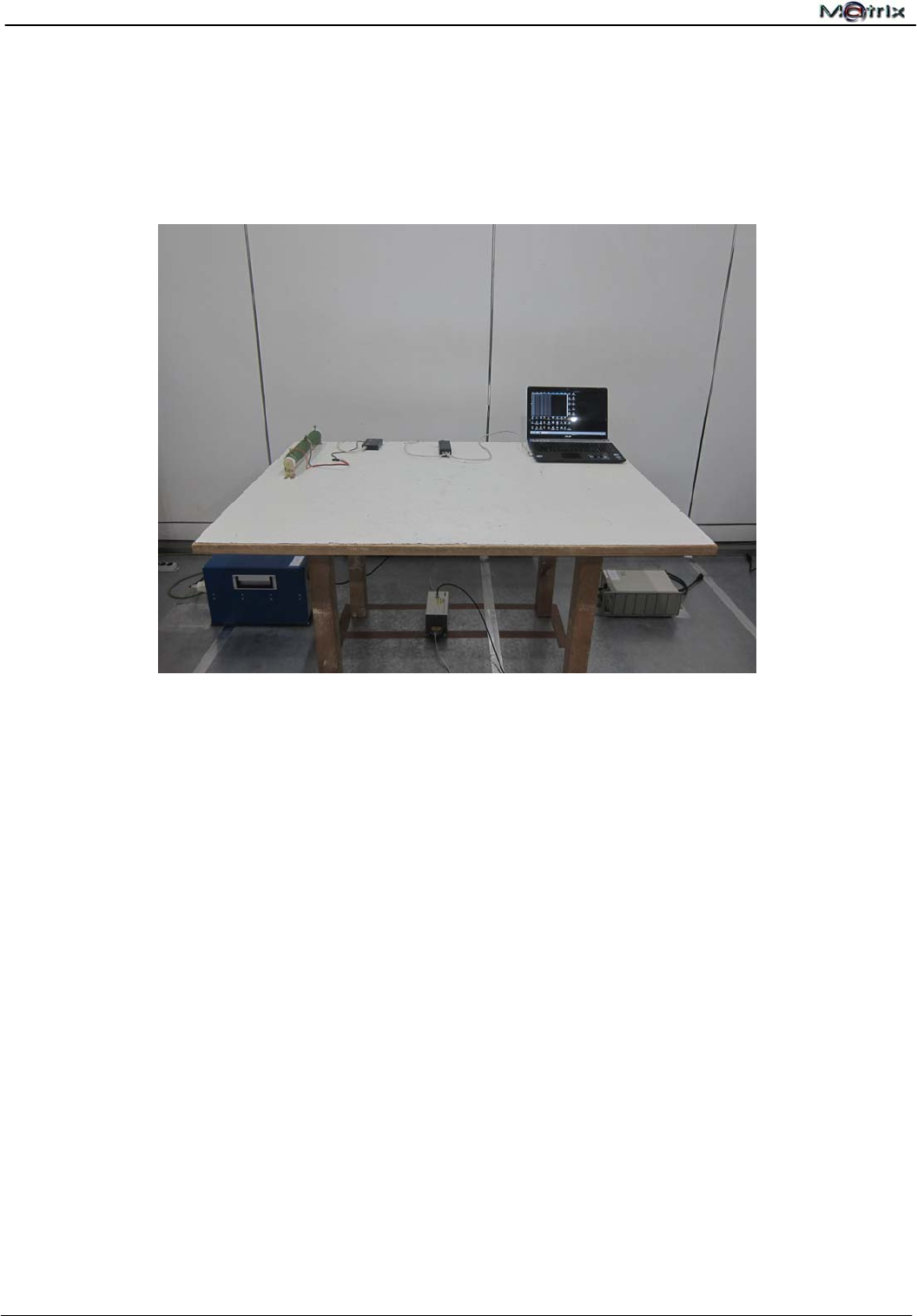
15.2 Telecommunication Port Conducted Test
Report No.:U10040802E-A01
CE EMC Testing Report Page 49 of 59
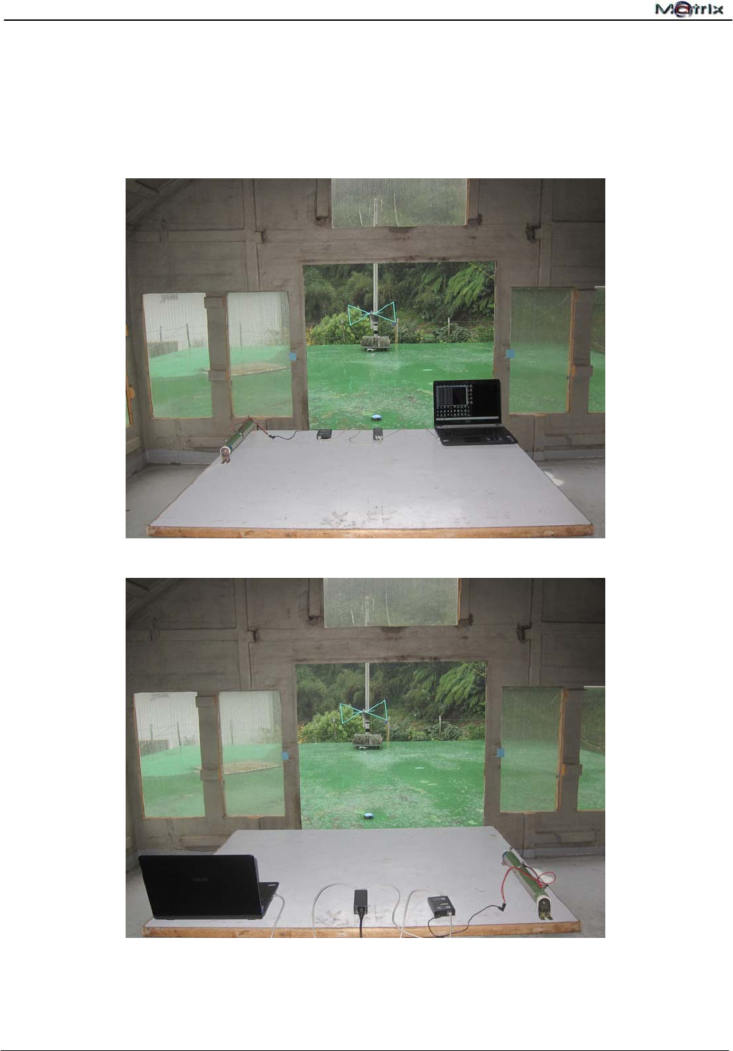
15.3 Radiated Disturbance Test – Below 1 GHz
Front View
Rear View
Report No.:U10040802E-A01
CE EMC Testing Report Page 50 of 59
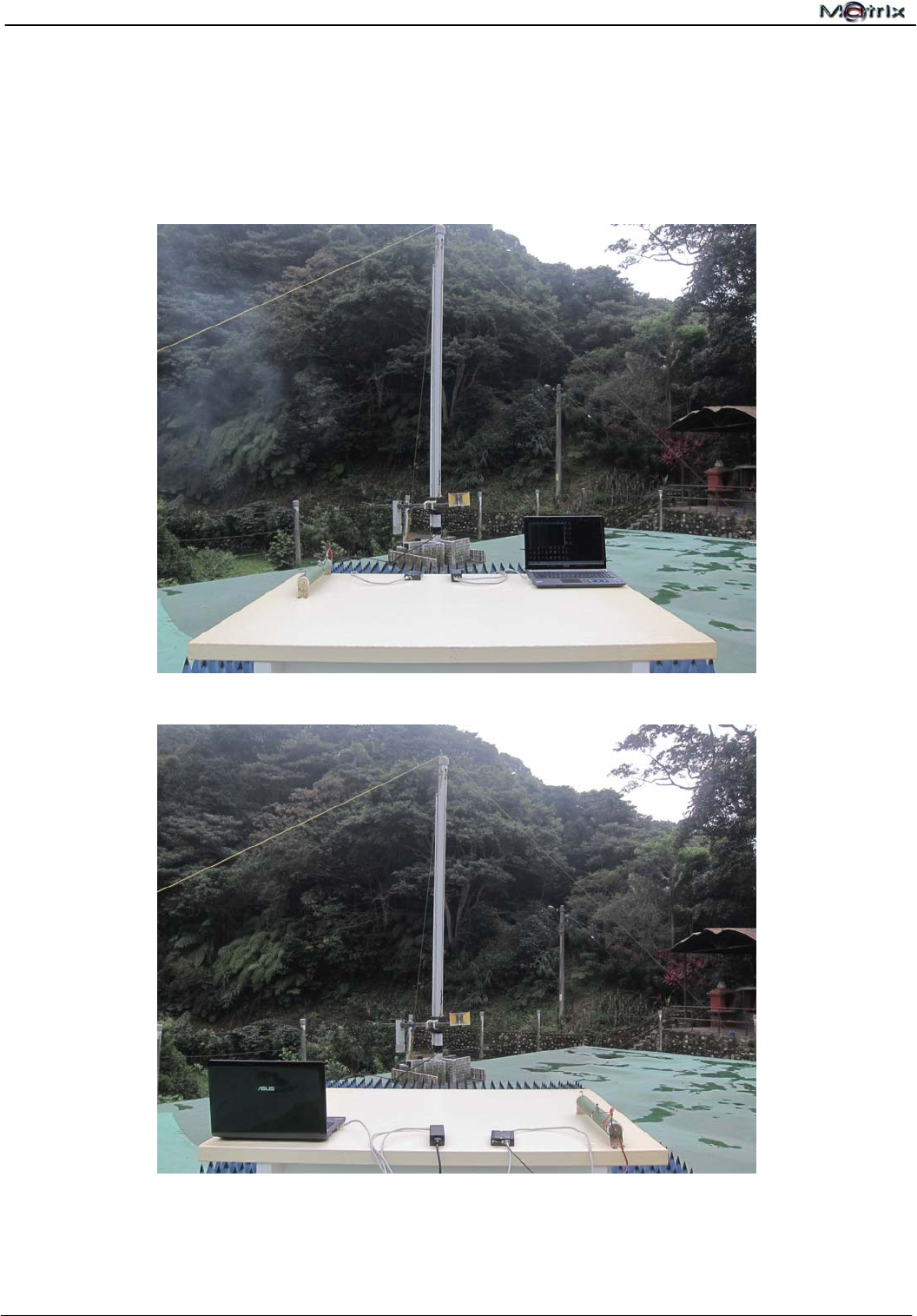
15.4 Radiated Disturbance Test – Above 1 GHz
Front View
Rear View
Report No.:U10040802E-A01
CE EMC Testing Report Page 51 of 59
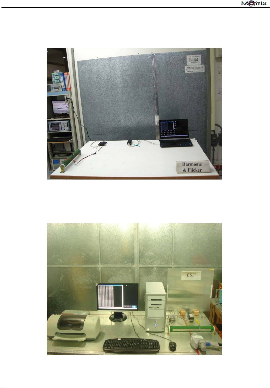
15.5 Harmonic Current & Voltage Fluctuations and Flicker Measurement
15.6 Electrostatic Discharge Immunity Test
Report No.:U10040802E-A01
CE EMC Testing Report Page 52 of 59
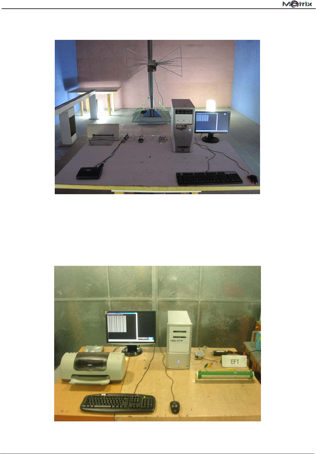
15.7 Radio-frequency, Electromagnetic Field Immunity Test
15.8 Electrical Fast Transient / Burst Immunity Test
Report No.:U10040802E-A01
CE EMC Testing Report Page 53 of 59
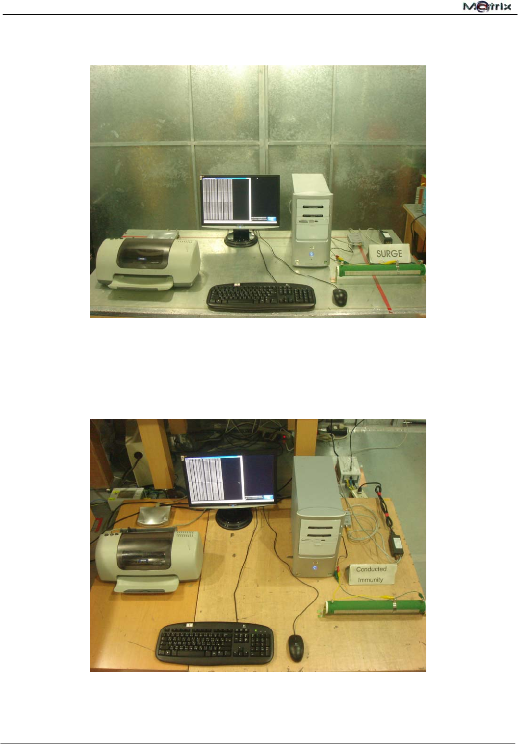
15.9 Surge Immunity Test
15.10 Radio-frequency, Conducted Disturbances Immunity Test
Report No.:U10040802E-A01
CE EMC Testing Report Page 54 of 59
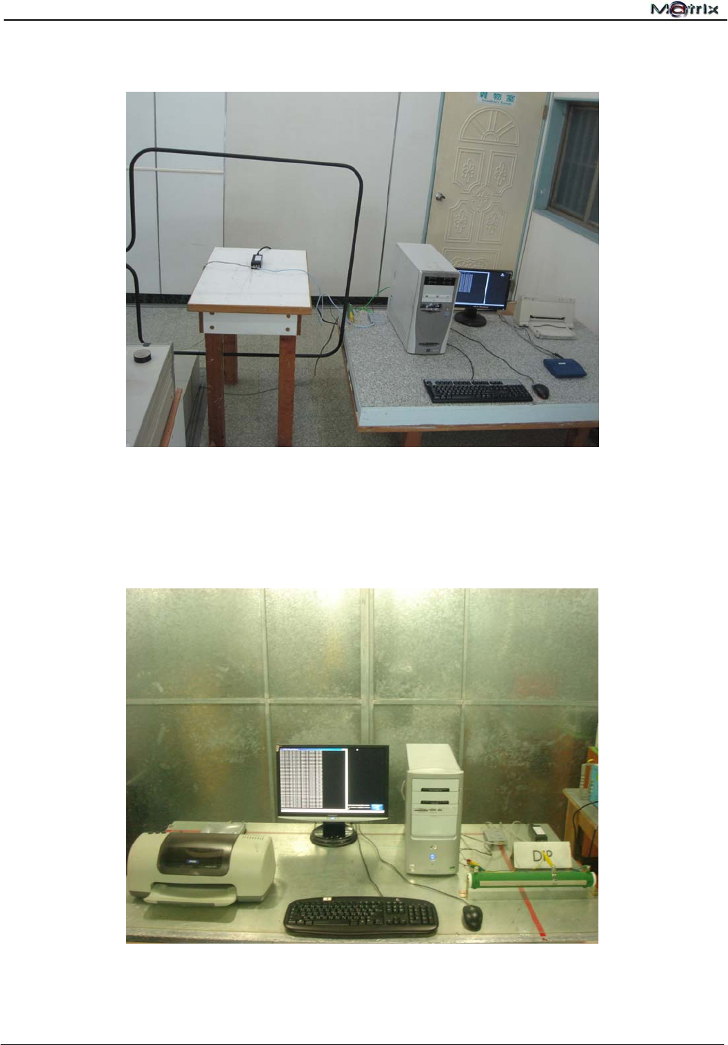
15.11 Power Frequency Magnetic Field Immunity Test
15.12 Voltage Dips, Short Interruptions Immunity Test
Report No.:U10040802E-A01
CE EMC Testing Report Page 55 of 59
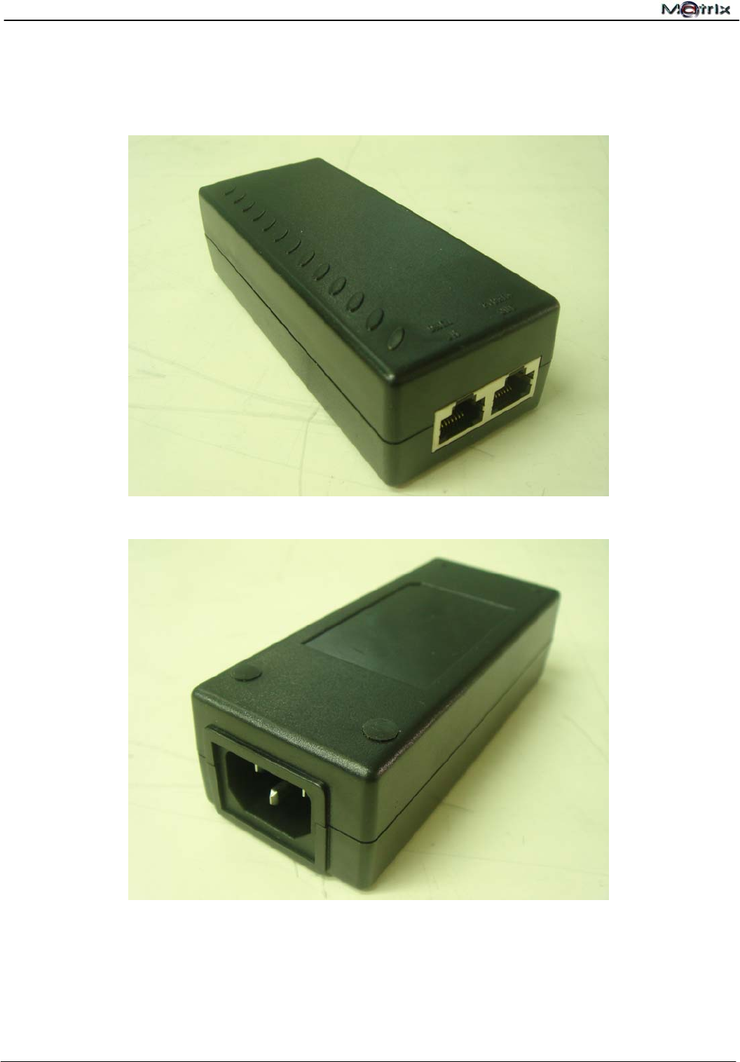
16 Photographs of EUT
Front View of the EUT
Rear View of the EUT
Report No.:U10040802E-A01
CE EMC Testing Report Page 56 of 59
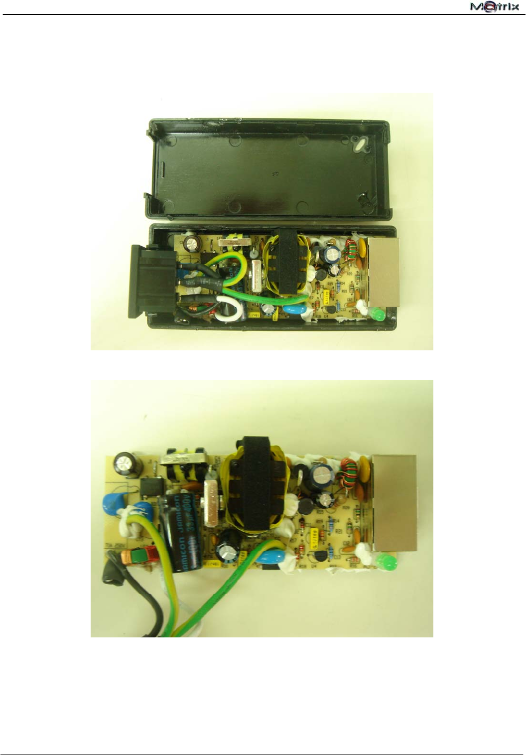
Inside View of the EUT
Front View of the PCB
Report No.:U10040802E-A01
CE EMC Testing Report Page 57 of 59
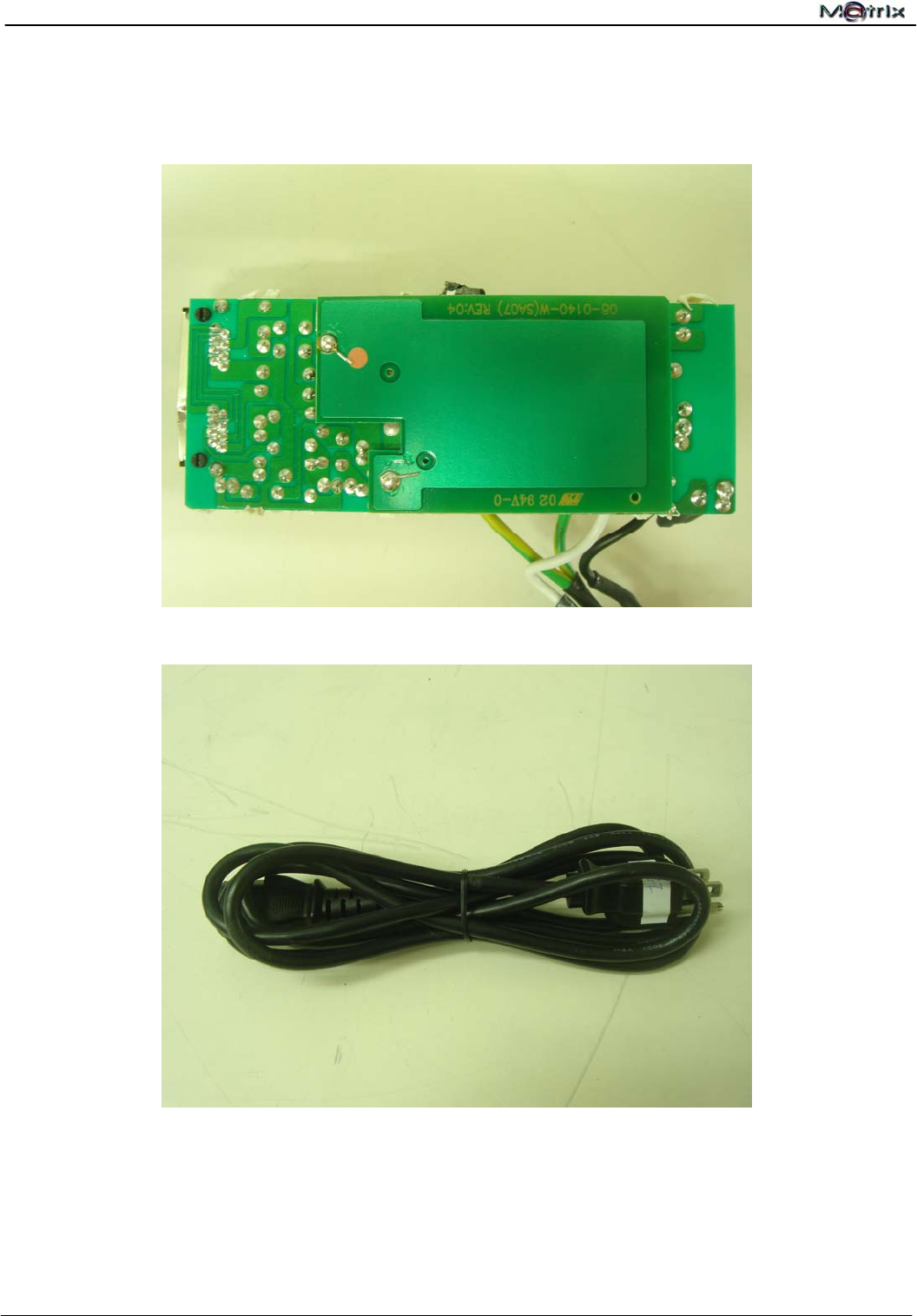
Rear View of the PCB
View of the Power Cable
Report No.:U10040802E-A01
CE EMC Testing Report Page 58 of 59
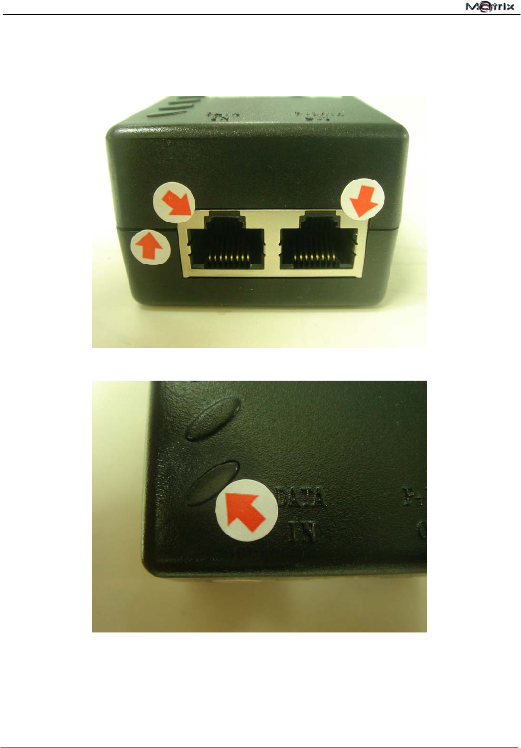
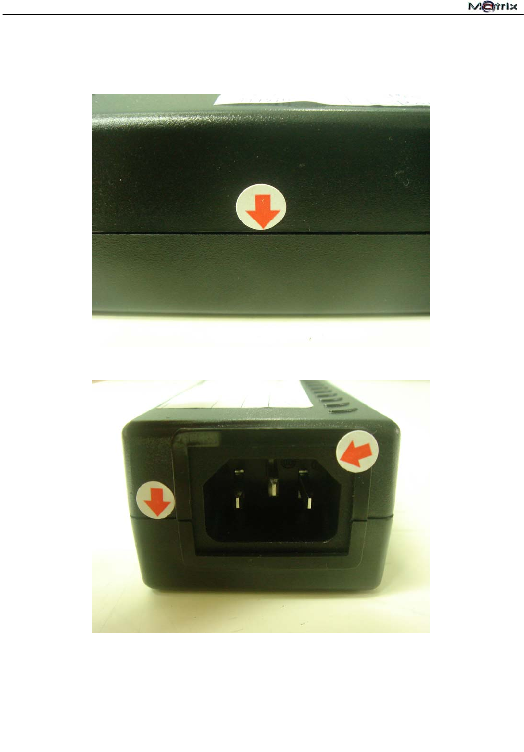
17 Photographs of ESD Test Points
View of ESD Test Points
View of ESD Test Point
Report No.:U10040802E-A01
CE EMC Testing Report Page 59 of 59
View of ESD Test Point
View of ESD Test Point
