CE Report
2016-04-11
: Pdf Ce Report CE__report CertsReports 510424 ProductFiles
Open the PDF directly: View PDF ![]() .
.
Page Count: 42
Shenzhen BST Technology Co., Ltd. Report No.: BST09081531321R-1
3F,Weames Technology Building, No. 10 Kefa Road, Science Park, Nanshan District, Shenzhen, Guangdong, China
Tel:86-755- 26747751~3(100 lines) Fax:86-755-26504032 http://www.bst-lab.com
Page 1 of 42
KAIWIN ELECTRONICS CO., LTD
EMC REPORT
Prepared For : KAIWIN ELECTRONICS CO., LTD
NanFang Industrial Area, Beizha, Humen, Dongguan City,
Guangdong Province, China
Product Name: USB Active Cable
Model : KWUU001P
Prepared By : Shenzhen BST Technology Co., Ltd.
3F,Weames Technology Building,No. 10 Kefa Road,
Science Park,Nanshan District,Shenzhen,Guangdong,China
Test Date: Aug. 19-20, 2009
Date of Report : Aug. 21, 2009
Report No.: BST09081531321R-1

Shenzhen BST Technology Co.,Ltd. Report No.: BST09081531321R-1
3F,Weames Technology Building,No. 10 Kefa Road,Science Park,Nanshan District,Shenzhen,Guangdong,China
Tel:86-755- 26747751~3(100 lines) Fax:86-755-26504032 http://www.bst-lab.com
Page 2 of 42
TABLE OF CONTENTS
TEST REPORT DECLARATION........................................................................................................5
1. TEST RESULTS SUMMARY.........................................................................................................6
2. GENERAL INFORMATION..........................................................................................................7
2.1. Report information ..................................................................................................................................7
2.2. Measurement Uncertainty .......................................................................................................................7
3. PRODUCT DESCRIPTION............................................................................................................8
3.1. EUT Description......................................................................................................................................8
3.2. Block Diagram of EUT Configuration....................................................................................................8
3.3. Operating Condition of EUT...................................................................................................................8
3.4. Test Conditions........................................................................................................................................8
3.5. Modifications...........................................................................................................................................8
3.6. Abbreviations ..........................................................................................................................................9
3.7. Performance Criterion.............................................................................................................................9
4. TEST EQUIPMENT USED...........................................................................................................10
4.1. For Conducted Emission Test ...............................................................................................................10
4.2. For Radiated Emission Measurement....................................................................................................10
4.3. For Harmonic / Flicker Test ..................................................................................................................10
4.4. For Electrostatic Discharge Immunity Test...........................................................................................10
4.5. For RF Strength Susceptibility Test ......................................................................................................10
4.6. For Electrical Fast Transient/Burst Immunity Test...............................................................................11
4.7. For Surge Test .......................................................................................................................................11
4.8. For Injected Currents Susceptibility Test..............................................................................................11
4.9. For Magnetic Field Immunity Test........................................................................................................11
4.10. For Voltage Dips and Interruptions Test...............................................................................................11
5. POWER LINE CONDUCTED EMISSION TEST......................................................................12
5.1. Block Diagram of Test Setup................................................................................................................12
5.2. Test Standard.........................................................................................................................................12
5.3. Power Line Conducted Emission Limit ................................................................................................12
5.4. EUT Configuration on Test...................................................................................................................12
5.5. Operating Condition of EUT.................................................................................................................13
5.6. Test Procedure.......................................................................................................................................13
5.7. Test Result.............................................................................................................................................13
6. RADIATED EMISSION TEST.....................................................................................................14
6.1. Open Site Setup Diagram......................................................................................................................14
6.2. Test Standard.........................................................................................................................................14
6.3. Radiated Emission Limit.......................................................................................................................14
6.4. EUT Configuration on Test...................................................................................................................14
6.5. Operating Condition of EUT.................................................................................................................15
6.6. Test Procedure.......................................................................................................................................15
6.7. Test Results ...........................................................................................................................................15
7. HARMONIC CURRENT EMISSION TEST ..............................................................................16
7.1. Block Diagram of Test Setup................................................................................................................16
7.2. Test Standard and Limit ........................................................................................................................16
7.3. Test Procedure.......................................................................................................................................17
7.4. Test Results ...........................................................................................................................................17

Shenzhen BST Technology Co.,Ltd. Report No.: BST09081531321R-1
3F,Weames Technology Building,No. 10 Kefa Road,Science Park,Nanshan District,Shenzhen,Guangdong,China
Tel:86-755- 26747751~3(100 lines) Fax:86-755-26504032 http://www.bst-lab.com
Page 3 of 42
8. VOLTAGE FLUCTUATIONS & FLICKER TEST...................................................................18
8.1. Block Diagram of Test Setup................................................................................................................18
8.2. Test Standard.........................................................................................................................................18
8.3. Operating Condition of EUT.................................................................................................................18
8.4. Test Results ...........................................................................................................................................18
9. ELECTROSTATIC DISCHARGE TEST....................................................................................19
9.1. Block Diagram of ESD Test Setup........................................................................................................19
9.2. Test Standard.........................................................................................................................................19
9.3. Severity Levels and Performance Criterion...........................................................................................19
9.4. EUT Configuration on Test...................................................................................................................19
9.5. Operating Condition of EUT.................................................................................................................19
9.6. Test Procedure.......................................................................................................................................20
9.7. Test Results ...........................................................................................................................................20
10. RF FIELD STRENGTH SUSCEPTIBILITY TEST...................................................................22
10.1. R/S Test Setup.......................................................................................................................................22
10.2. Test Standard.........................................................................................................................................22
10.3. Severity Levels and Performance Criterion...........................................................................................22
10.4. EUT Configuration on Test...................................................................................................................23
10.5. Operating Condition of EUT.................................................................................................................23
10.6. Test Procedure.......................................................................................................................................23
10.7. Test Results ...........................................................................................................................................23
11. ELECTRICAL FAST TRANSIENT/BURST TEST...................................................................25
11.1. EFT Test Setup......................................................................................................................................25
11.2. Test Standard.........................................................................................................................................25
11.3. Severity Levels and Performance Criterion...........................................................................................25
11.4. EUT Configuration on Test...................................................................................................................25
11.5. Operating Condition of EUT.................................................................................................................25
11.6. Test Procedure.......................................................................................................................................26
11.7. Test Results ...........................................................................................................................................26
12. SURGE TEST .................................................................................................................................28
12.1. Surge Test Setup....................................................................................................................................28
12.2. Test Standard.........................................................................................................................................28
12.3. Severity Levels and Performance Criterion...........................................................................................28
12.4. EUT Configuration on Test...................................................................................................................28
12.5. Operating Condition of EUT.................................................................................................................28
12.6. Test Procedure.......................................................................................................................................29
12.7. Test Results ...........................................................................................................................................29
13. INJECTED CURRENTS SUSCEPTIBILITY TEST .................................................................31
13.1. Block Diagram of Test AC Mains Setup...............................................................................................31
13.2. Test Standard.........................................................................................................................................31
13.3. Severity Levels and Performance Criterion...........................................................................................31
13.4. EUT Configuration on Test...................................................................................................................31
13.5. Operating Condition of EUT.................................................................................................................31
13.6. Test Procedure.......................................................................................................................................32
13.7. Test Results ...........................................................................................................................................32
14. VOLTAGE DIPS AND INTERRUPTIONS TEST .....................................................................34
14.1. Voltage Dips and Interruptions Test Setup ...........................................................................................34

Shenzhen BST Technology Co.,Ltd. Report No.: BST09081531321R-1
3F,Weames Technology Building,No. 10 Kefa Road,Science Park,Nanshan District,Shenzhen,Guangdong,China
Tel:86-755- 26747751~3(100 lines) Fax:86-755-26504032 http://www.bst-lab.com
Page 4 of 42
14.2. Test Standard.........................................................................................................................................34
14.3. Severity Levels and Performance Criterion...........................................................................................34
14.4. EUT Configuration on Test...................................................................................................................34
14.5. Operating Condition of EUT.................................................................................................................34
14.6. Test Procedure.......................................................................................................................................35
14.7. Test Result.............................................................................................................................................35
APPENDIX I .........................................................................................................................................37
APPENDIX II........................................................................................................................................40
Shenzhen BST Technology Co., Ltd. Report No.: BST09081531321R-1
3F,Weames Technology Building, No. 10 Kefa Road, Science Park, Nanshan District, Shenzhen, Guangdong, China
Tel:86-755- 26747751~3(100 lines) Fax:86-755-26504032 http://www.bst-lab.com
Page 5 of 42
TEST REPORT DECLARATION
Applicant : KAIWIN ELECTRONICS CO., LTD
Address :
NanFang Industrial Area, Beizha, Humen, Dongguan City,
Guangdong Province, China
EUT Description : USB Active Cable
Model Number : KWUU001P
Test Standards:
EN 55022:2006+A1:2007, EN61000-3-2: 2006 & EN61000-3-3:2008
EN 55024:1998+ A2:2003
(EN61000-4-2:1995+A2:2001, EN61000-4-3:2006+A1:2008
EN61000-4-4:2004, EN61000-4-5:2006,
EN61000-4-6:2007, EN61000-4-8:1993+A1:2001,EN61000-4-11:2004)
The EUT described above is tested by BST Technology Co., Ltd. EMC Laboratory to determine the
maximum emissions from the EUT and ensure the EUT to be compliance with the immunity
requirements of the EUT. BST Technology Co., Ltd. EMC Laboratory is assumed full responsibility
for the accuracy of the test results. Also, this report shows that the EUT technically complies with the
2004/108/EC directive and its amendment requirements.
The test report is valid for above tested sample only and shall not be reproduced in part without
written approval of the laboratory.
Prepared by :
Assistant
Reviewer :
Supervisor
Approved & Authorized Signer :
Christina / Manager

Shenzhen BST Technology Co., Ltd. Report No.: BST09081531321R-1
3F,Weames Technology Building, No. 10 Kefa Road, Science Park, Nanshan District, Shenzhen, Guangdong, China
Tel:86-755- 26747751~3(100 lines) Fax:86-755-26504032 http://www.bst-lab.com
Page 6 of 42
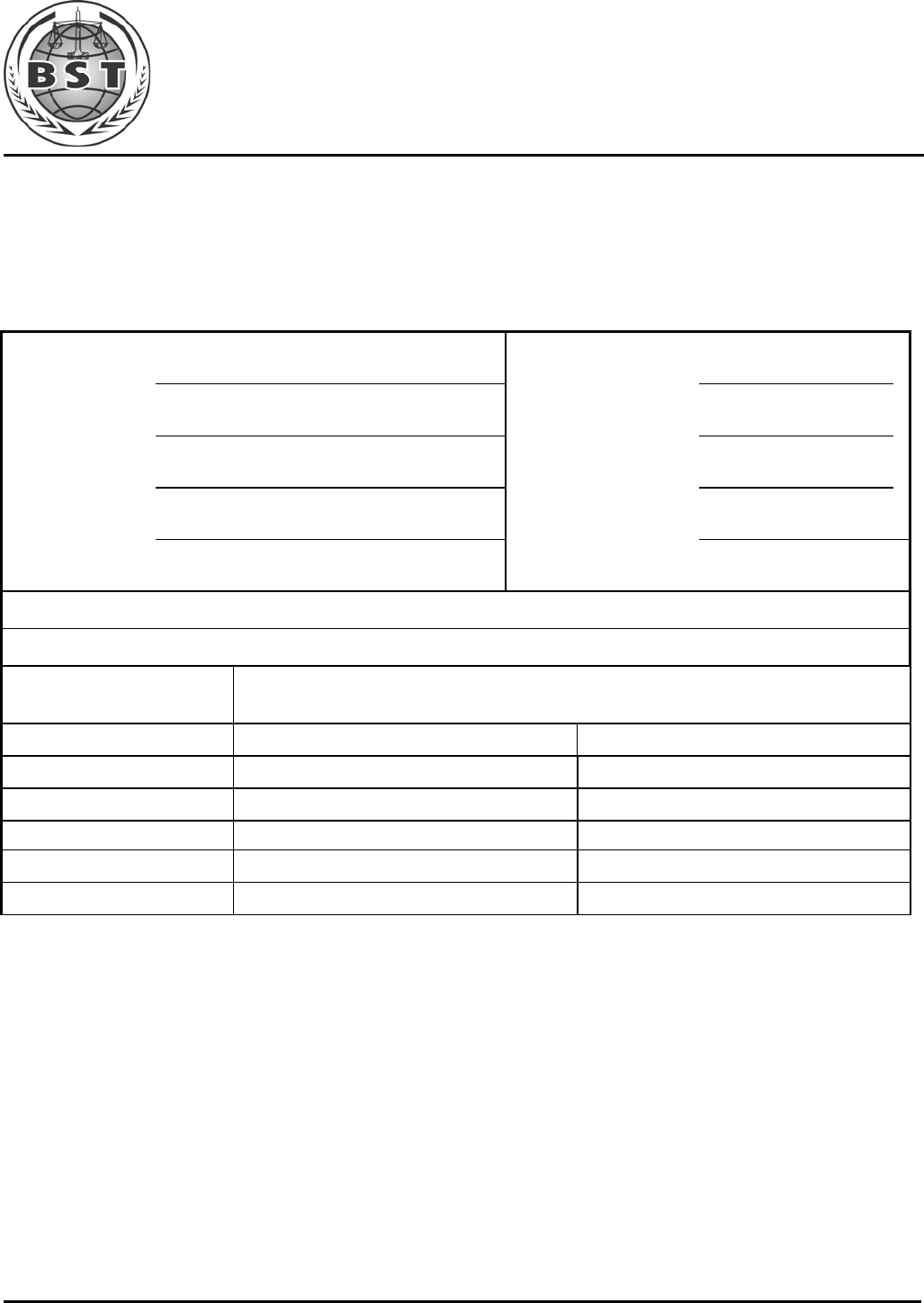
1. TEST RESULTS SUMMARY
Table 1 Test Results Summary
Test Items Test Results
Radiated Emission PASS
Conducted Disturbance N/A
Harmonic Current N/A
Voltage Fluctuation and Flicker N/A
Electrostatic Discharge Immunity PASS
Radiated Electromagnetic Fields Immunity PASS
Electric Fast Transient Burst Immunity N/A
Surge Immunity N/A
Injected currents susceptibility test N/A
Voltage dips and interruptions Immunity N/A

Shenzhen BST Technology Co.,Ltd. Report No.: BST09081531321R-1
3F,Weames Technology Building,No. 10 Kefa Road,Science Park,Nanshan District,Shenzhen,Guangdong,China
Tel:86-755- 26747751~3(100 lines) Fax:86-755-26504032 http://www.bst-lab.com
Page 7 of 42
2. GENERAL INFORMATION
2.1. Report information
2.1.1.This report is not a certificate of quality; it only applies to the sample of the specific
product/equipment given at the time of its testing. The results are not used to indicate or
imply that they are application to the similar items. In addition, such results must not be
used to indicate or imply that BST approves recommends or endorses the manufacture,
supplier or use of such product/equipment, or that BST in any way guarantees the later
performance of the product/equipment.
2.1.2.The sample/s mentioned in this report is/are supplied by Applicant, BST therefore
assumes no responsibility for the accuracy of information on the brand name, model
number, origin of manufacture or any information supplied.
2.1.3.Additional copies of the report are available to the Applicant at an additional fee. No third
part can obtain a copy of this report through BST, unless the applicant has authorized BST
in writing to do so.
2.2. Measurement Uncertainty
Available upon request.
Shenzhen BST Technology Co., Ltd. Report No.: BST09081531321R-1
3F,Weames Technology Building, No. 10 Kefa Road, Science Park, Nanshan District, Shenzhen, Guangdong, China
Tel:86-755- 26747751~3(100 lines) Fax:86-755-26504032 http://www.bst-lab.com
Page 8 of 42
3. PRODUCT DESCRIPTION
3.1. EUT Description
Description : USB Active Cable
Applicant :
KAIWIN ELECTRONICS CO., LTD
NanFang Industrial Area, Beizha, Humen, Dongguan City,
Guangdong Province, China
Manufacturer : KAIWIN ELECTRONICS CO., LTD
NanFang Industrial Area, Beizha, Humen, Dongguan City,
Guangdong Province, China
Model Number : KWUU001P
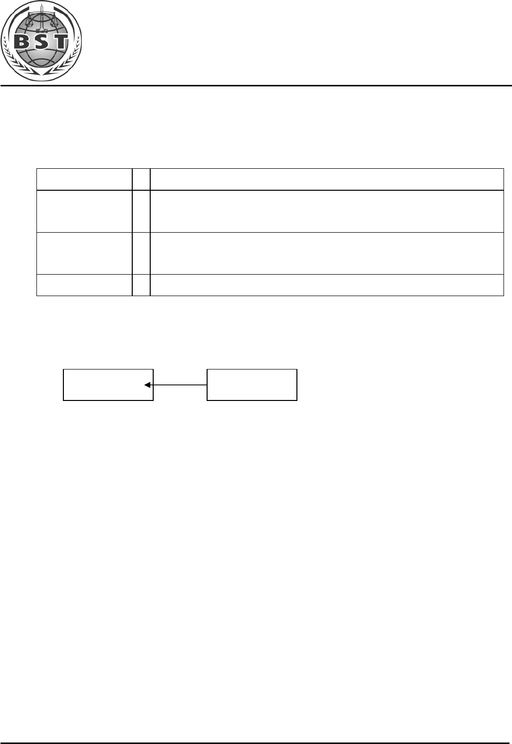
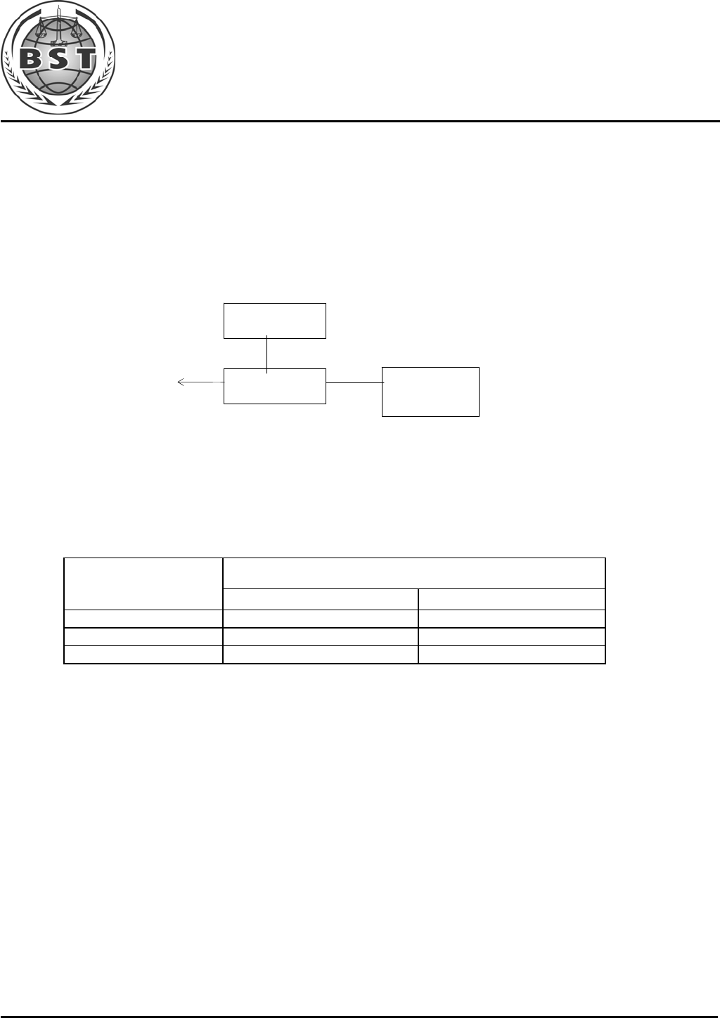
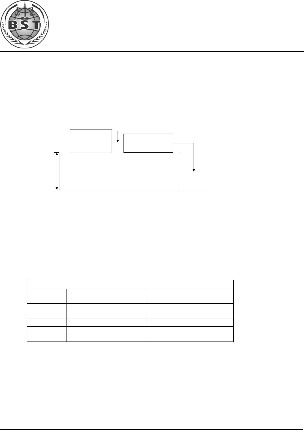
3.2. Block Diagram of EUT Configuration
3.3. Operating Condition of EUT
Test mode 1: TX
3.4. Test Conditions
Temperature: 23-26℃
Relative Humidity: 55-68 %
3.5. Modifications
No modification was made.
EUT

Shenzhen BST Technology Co.,Ltd. Report No.: BST09081531321R-1
3F,Weames Technology Building,No. 10 Kefa Road,Science Park,Nanshan District,Shenzhen,Guangdong,China
Tel:86-755- 26747751~3(100 lines) Fax:86-755-26504032 http://www.bst-lab.com
Page 9 of 42
3.6. Abbreviations
AC Alternating Current
AMN Artificial Mains Network
DC Direct Current
EM ElectroMagnetic
EMC ElectroMagnetic Compatibility
EUT Equipment Under Test
IF Intermediate Frequency
RF Radio Frequency
rms root mean square
EMI Electromagnetic Interference
EMS Electromagnetic Susceptibility
3.7. Performance Criterion
Criterion A: The equipment shall continue to operate as intended without operator
intervention. No degradation of performance of loss of function is allowed below a
performance level specified by the manufacturer when the equipment is used as intended.
Criterion B: After the test, the equipment shall continue to operate as intended without
operator intervention. No degradation of performance or loss of function is allowed, after the
application of the phenomena below a performance level specified by the manufacturer,
when the equipment is used as intended.
Criterion C: Loss of function is allowed, provided the function is self-recoverable, or can be
restored by the operation of the controls by the user in accordance with the manufacturer’s
instructions.
Shenzhen BST Technology Co.,Ltd. Report No.: BST09081531321R-1
3F,Weames Technology Building,No. 10 Kefa Road,Science Park,Nanshan District,Shenzhen,Guangdong,China
Tel:86-755- 26747751~3(100 lines) Fax:86-755-26504032 http://www.bst-lab.com
Page 10 of 42
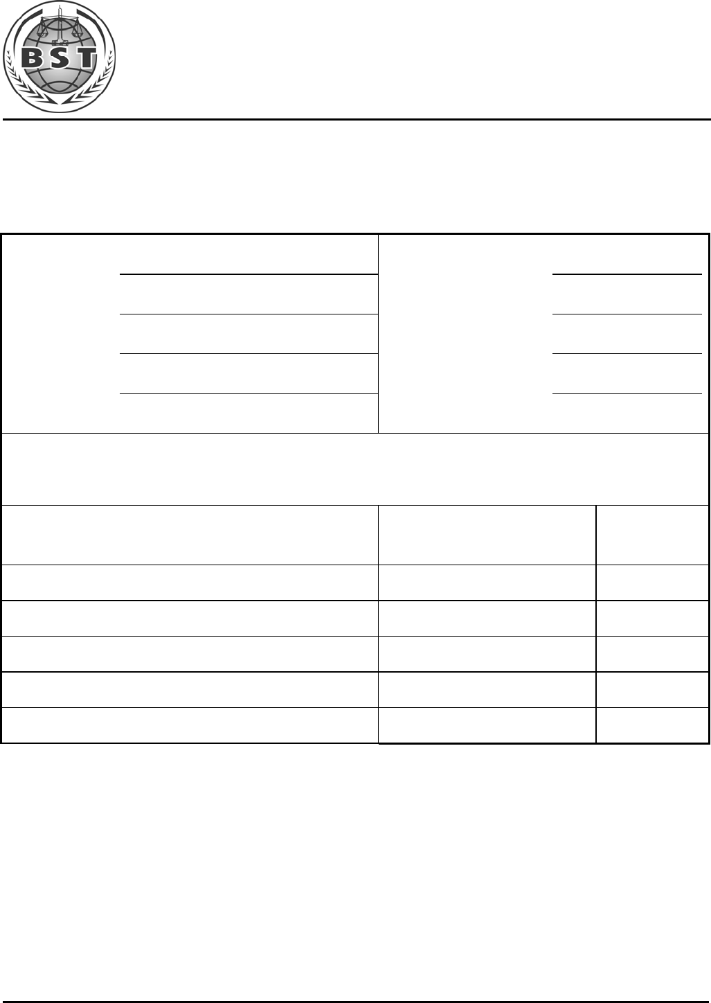
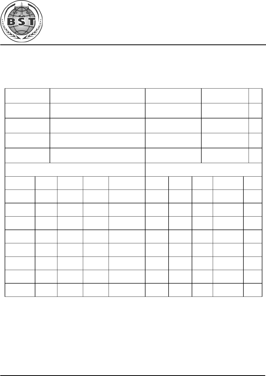
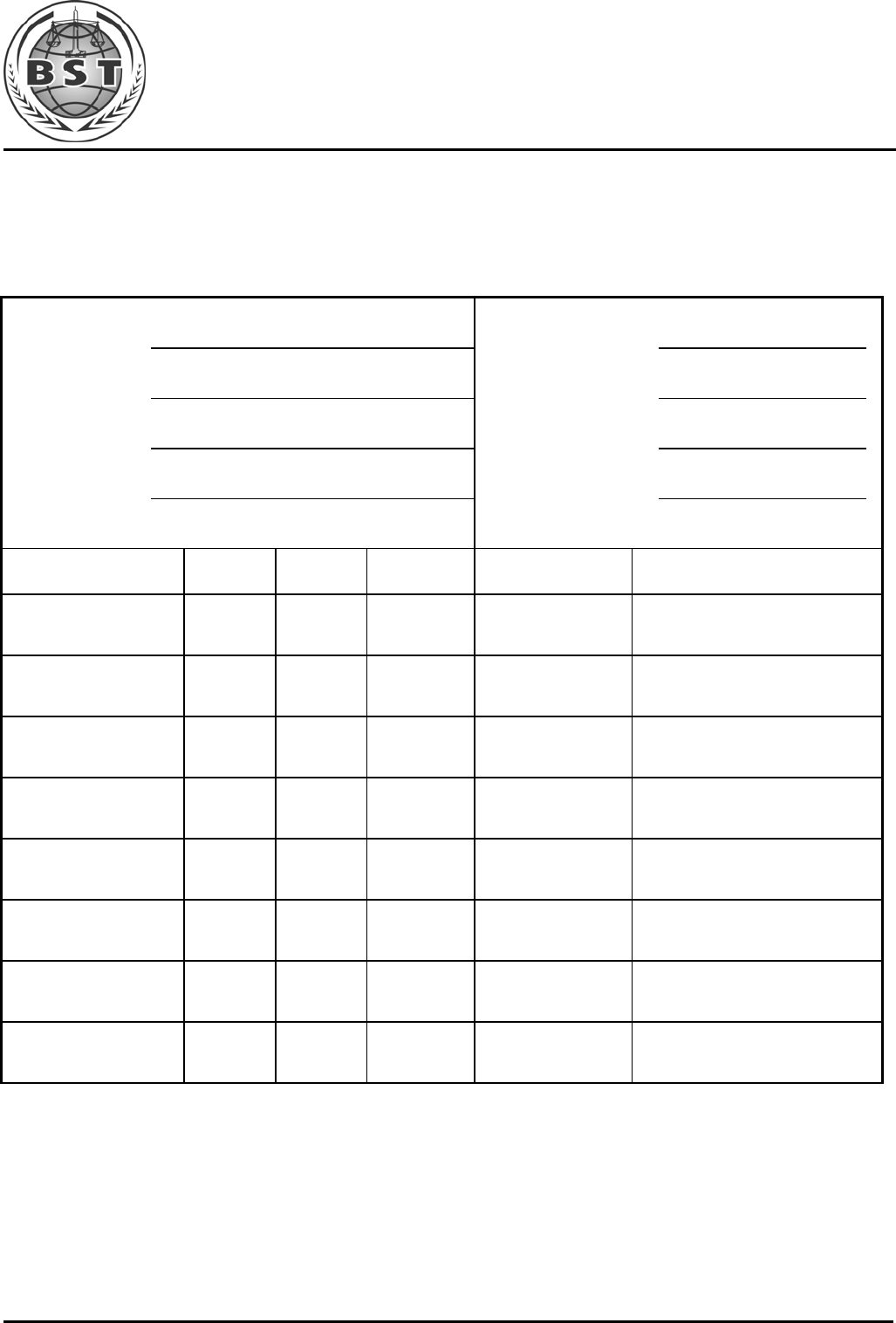
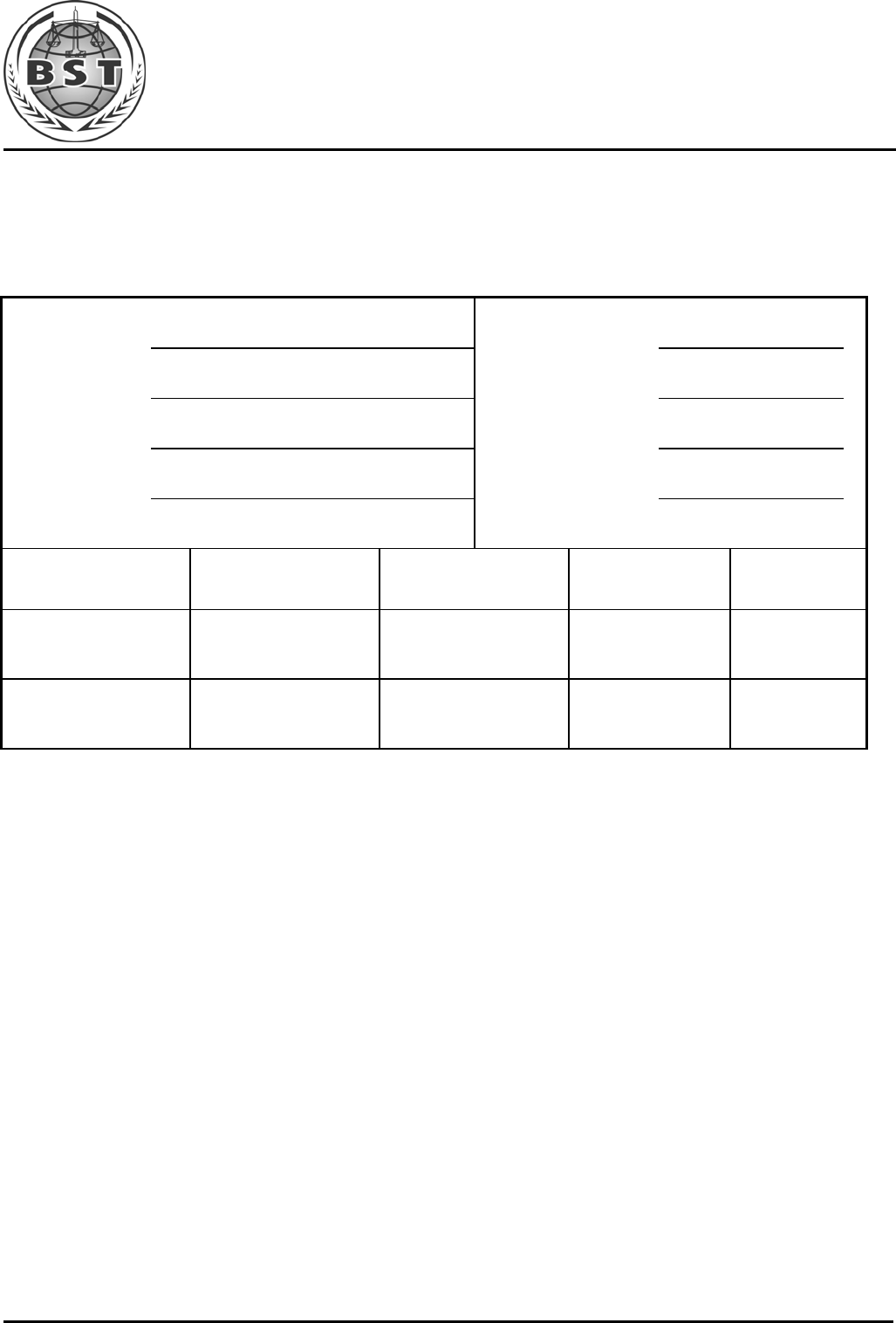
4. TEST EQUIPMENT USED
4.1. For Conducted Emission Test
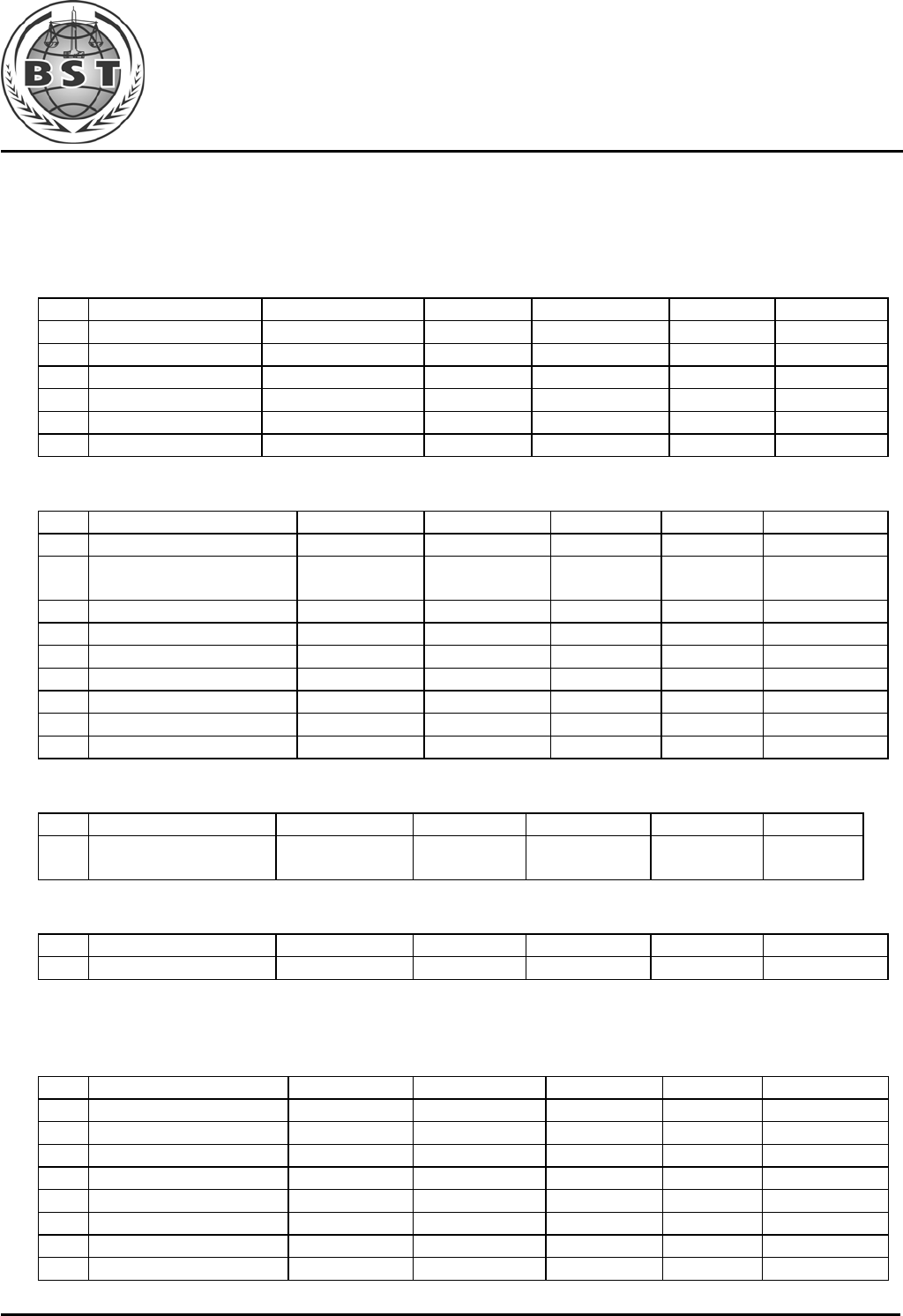
Item Equipment Manufacturer Model No. Serial No. Last Cal. Cal. Interval
1. Test Receiver Rohde & Schwarz ESHS30 828985/018 Jun. 01, 09 1 Year
2. Pulse Limiter Rohde & Schwarz ESH3-Z2 100006 Jun. 01, 09 1 Year
3. L.I.S.N. Rohde & Schwarz ESH2-Z5 834549/005 Jun. 01, 09 1 Year
4. Conical Emtek N/A N/A N/A N/A
5. Voltage Probe Schwarzbeck TK9416 N/A Jun. 01.09 1 Year
6. Coaxial Switch Anritsu MP59B 6100214550 Jun. 01, 09 1 Year
4.2. For Radiated Emission Measurement
Item Equipment Manufacturer Model No. Serial No. Last Cal. Cal. Interval
1. Spectrum Analyzer ANRITSU MS2661C 6200140915 Jun 01,09 1 Year
2. Test Receiver Rohde&Schwar
z ESC830 828982/018 Jun 01,09 1 Year
3. Bilog Antenna Schwarzbeck VULB9163 142 Jun 01,09 1 Year
4. 50 Coaxial Switch Anritsu Corp MP59B 6100237248 Jun 01,09 1 Year
5. Cable Schwarzbeck AK9513 ACRX1 Jun 01,09 1 Year
6. Cable Rosenberger N/A FR2RX2 Jun 01,09 1 Year
7. Cable Schwarzbeck AK9513 CRRX2 Jun 01,09 1 Year
8. Cable Schwarzbeck AK9513 CRRX2 Jun 01,09 1 Year
9. Signal Generator HP 864A 3625U00573 Jun 01,09 1 Year
4.3. For Harmonic / Flicker Test
Item Equipment Manufacturer Model No. Serial No. Last Cal. Cal. Interval
1. Power Frequency test
system HAEFELY PHF555 080419-03 Jun. 01, 09 1 Year
4.4. For Electrostatic Discharge Immunity Test
Item Equipment Manufacturer Model No. Serial No. Last Cal. Cal. Interval
1. ESD Tester HAEFELY PSD 1600 H911’292 Jun. 02, 09 1 Year
4.5. For RF Strength Susceptibility Test
Item Equipment Manufacturer Model No. Serial No. Last Cal. Cal. Interval
1. Signal Generator HP 8648A 3633A02081 Jun. 03, 09 1 Year
2. Amplifier A&R 500A100 17034 NCR NCR
3. Amplifier A&R 100W/1000M1 17028 NCR NCR
4. Isotropic Field Monitor A&R FM2000 16829 NCR NCR
5. Isotropic Field Probe A&R FLW220100 16755 Jun. 03, 09 1 Year
6. Biconic Antenna EMCO 3108 9507-2534 NCR NCR
7. Log-periodic Antenna A&R AT1080 16812 NCR NCR
8. PC N/A 486DX2 N/A N/A N/A
Shenzhen BST Technology Co.,Ltd. Report No.: BST09081531321R-1
3F,Weames Technology Building,No. 10 Kefa Road,Science Park,Nanshan District,Shenzhen,Guangdong,China
Tel:86-755- 26747751~3(100 lines) Fax:86-755-26504032 http://www.bst-lab.com
Page 11 of 42
4.6. For Electrical Fast Transient/Burst Immunity Test
Item Equipment Manufacturer Model No. Serial No. Last Cal. Cal. Interval
1. Burst Tester HAEFELY PEFT 4010 080981-16 Jun. 01, 09 1 Year
4.7. For Surge Test
Item Equipment Manufacturer Model No. Serial No. Last Cal. Cal. Interval
1. Surge Tester HAEFELY PSURGE4.1 080107-04 Jun. 01, 09 1 Year
4.8. For Injected Currents Susceptibility Test
Item Equipment Manufacturer Model No. Serial No. Last Cal. Cal. Interval
1. Simulator EMTEST CWS 500C 0900-12 Jun. 01, 09 1 Year
2. CDN EMTEST CDN-M2 510010010010 Jun. 01, 09 1 Year
3. VDN EMTEST CDN-M3 0900-11 Jun. 01, 09 1 Year
4. Injection Clamp EMTEST F-2031-23MM 368 Jun. 01, 09 1 Year
5. Attenuator EMTEST ATT6 0010222a Jun. 01, 09 1 Year
4.9. For Magnetic Field Immunity Test
Item Equipment Manufacturer Model No. Serial No. Last Cal. Cal. Interval
1. Magnetic Field Tester HEAFELY MAG100.1 083858-10 Jun. 01, 09 1 Year
4.10.For Voltage Dips and Interruptions Test
Item Equipment Manufacturer Model No. Serial No. Last Cal. Cal. Interval
2. Dips Tester HEAFELY PLINE 1610 083732-18 Jun. 01, 09 1 Year
Shenzhen BST Technology Co.,Ltd. Report No.: BST09081531321R-1
3F,Weames Technology Building,No. 10 Kefa Road,Science Park,Nanshan District,Shenzhen,Guangdong,China
Tel:86-755- 26747751~3(100 lines) Fax:86-755-26504032 http://www.bst-lab.com
Page 12 of 42
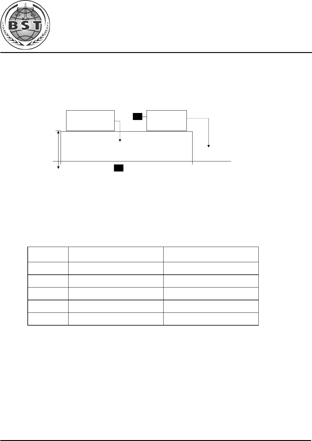
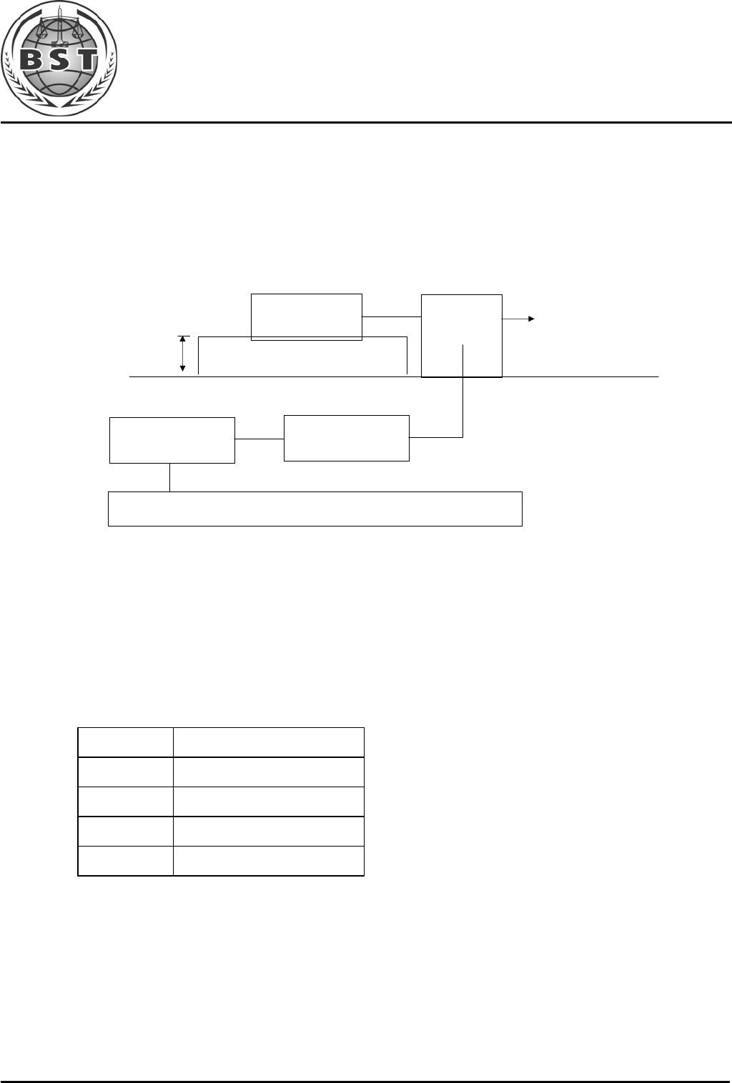
5. POWER LINE CONDUCTED EMISSION TEST
5.1. Block Diagram of Test Setup
5.2. Test Standard
EN 55022:2006+A1:2007
5.3. Power Line Conducted Emission Limit
Limits dB(µV)
Frequency
MHz Quasi-peak Level Average Level
0.15 ~ 0.50 66 ~ 56* 56 ~ 46*
0.50 ~ 5.00 56 46
5.00 ~ 30.00 60 50
Notes: 1. *Decreasing linearly with logarithm of frequency.
2. The lower limit shall apply at the transition frequencies.
5.4. EUT Configuration on Test
The following equipments are installed on conducted emission test to meet EN55022
requirement and operating in a manner, which tends to maximize its emission characteristics
in a normal application.
5.4.1.EUT Information
Model Number : KWUU001P
Serial Number : N/A
Manufacturer : KAIWIN ELECTRONICS CO., LTD
L.I.S.N. #1
AC Mains
Test Receiver
EUT

Shenzhen BST Technology Co.,Ltd. Report No.: BST09081531321R-1
3F,Weames Technology Building,No. 10 Kefa Road,Science Park,Nanshan District,Shenzhen,Guangdong,China
Tel:86-755- 26747751~3(100 lines) Fax:86-755-26504032 http://www.bst-lab.com
Page 13 of 42
5.5. Operating Condition of EUT
5.5.1.Setup the EUT and simulators as shown in Section 5.1.
5.5.2.Turn on the power of all equipments.
5.5.3.Let the EUT work in test modes (EUT WORKING) and test it.
5.6. Test Procedure
The EUT is put on the ground and connected to the AC mains through a Artificial Mains
Network (AMN). This provided 50ohm-coupling impedance for the tested equipments.
Both sides of AC line are checked to find out the maximum conducted emission levels
according to the EN55022 regulations during conducted emission test.
The bandwidth of the test receiver (R&S Test Receiver ESHS30) is set at 10KHz.
The frequency range from 150 KHz to 30 MHz is investigated.
5.7. Test Result
N/A
Shenzhen BST Technology Co.,Ltd. Report No.: BST09081531321R-1
3F,Weames Technology Building,No. 10 Kefa Road,Science Park,Nanshan District,Shenzhen,Guangdong,China
Tel:86-755- 26747751~3(100 lines) Fax:86-755-26504032 http://www.bst-lab.com
Page 14 of 42
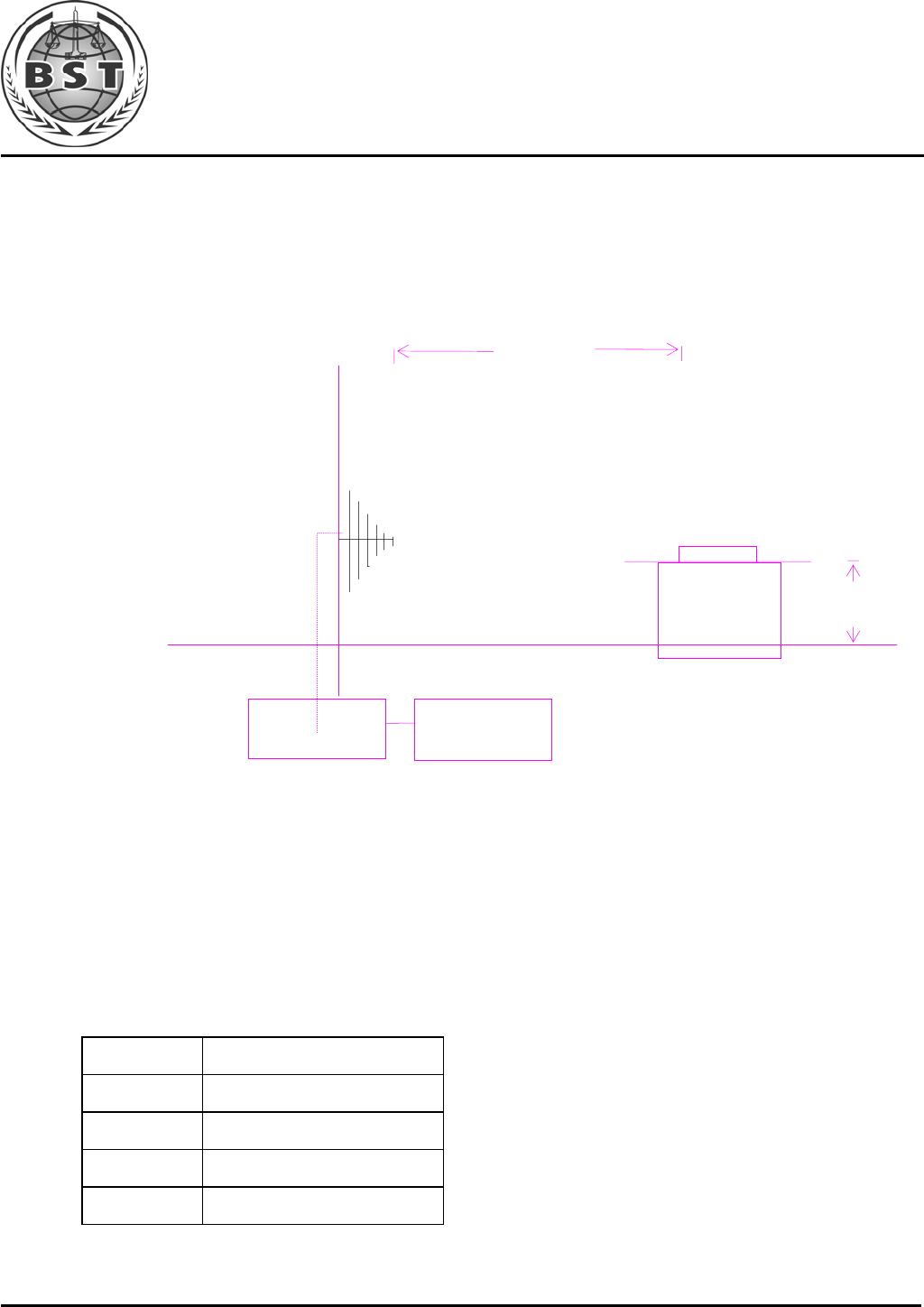
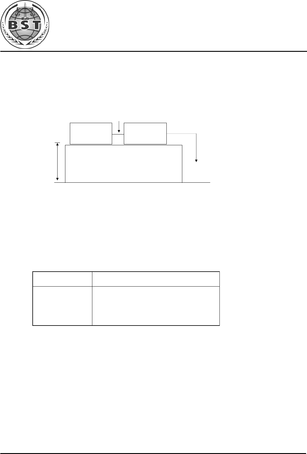
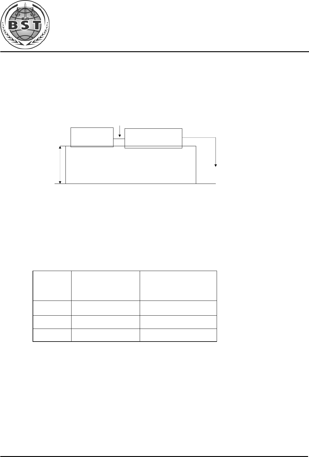
6. RADIATED EMISSION TEST
6.1. Open Site Setup Diagram
6.2. Test Standard
EN 55022:2006+A1:2007
6.3. Radiated Emission Limit
All emanations from a Class B computing devices or system, including any network of
conductors and apparatus connected thereto, shall not exceed the level of field strengths
specified below:
FREQUENCY
(MHz) DISTANCE
(Meters) FIELD STRENGTHS LIMITS
(dBµV/m)
30 ~ 230 3 40
230 ~ 1000 3 47
Note:(1) The tighter limit shall apply at the edge between two frequency bands.
(2) Distance refers to the distance in meters between the measuring instruments
antenna and the closed point of any part of the EUT.
6.4. EUT Configuration on Test
The EN55022 Class B regulations test method must be used to find the maximum emission
during radiated emission test.
ANTENNA TOWER
ANTENNA ELEVATION VARIES FROM 1 TO 4 METERS
GROUND PLANE
3 METERS
EUT
TURN TABLE 0.8 METER

Shenzhen BST Technology Co.,Ltd. Report No.: BST09081531321R-1
3F,Weames Technology Building,No. 10 Kefa Road,Science Park,Nanshan District,Shenzhen,Guangdong,China
Tel:86-755- 26747751~3(100 lines) Fax:86-755-26504032 http://www.bst-lab.com
Page 15 of 42
6.5. Operating Condition of EUT
6.5.1.Setup the EUT as shown on Section 5.1.
6.5.2.Turn on the power of all equipments.
6.5.3.Let the EUT work in test mode and measure it.
6.6. Test Procedure
The EUT is placed on a turn table which is 0.8 meter above ground. The turn table can
rotate 360 degrees to determine the position of the maximum emission level. The EUT is
set 3 meters away from the receiving antenna which is mounted on a antenna tower. The
antenna can move up and down between 1 to 4 meters to find out the maximum emission
level. Broadband antenna (calibrated by dipole antenna) are used as a receiving antenna.
Both horizontal and vertical polarization of the antenna are set on test.
The bandwidth setting on the test receiver (R&S TEST RECEIVER ESCS20) is 120 KHz.
The EUT is tested in Anechoic Chamber. and all the scanning waveform is put in
Appendix I.
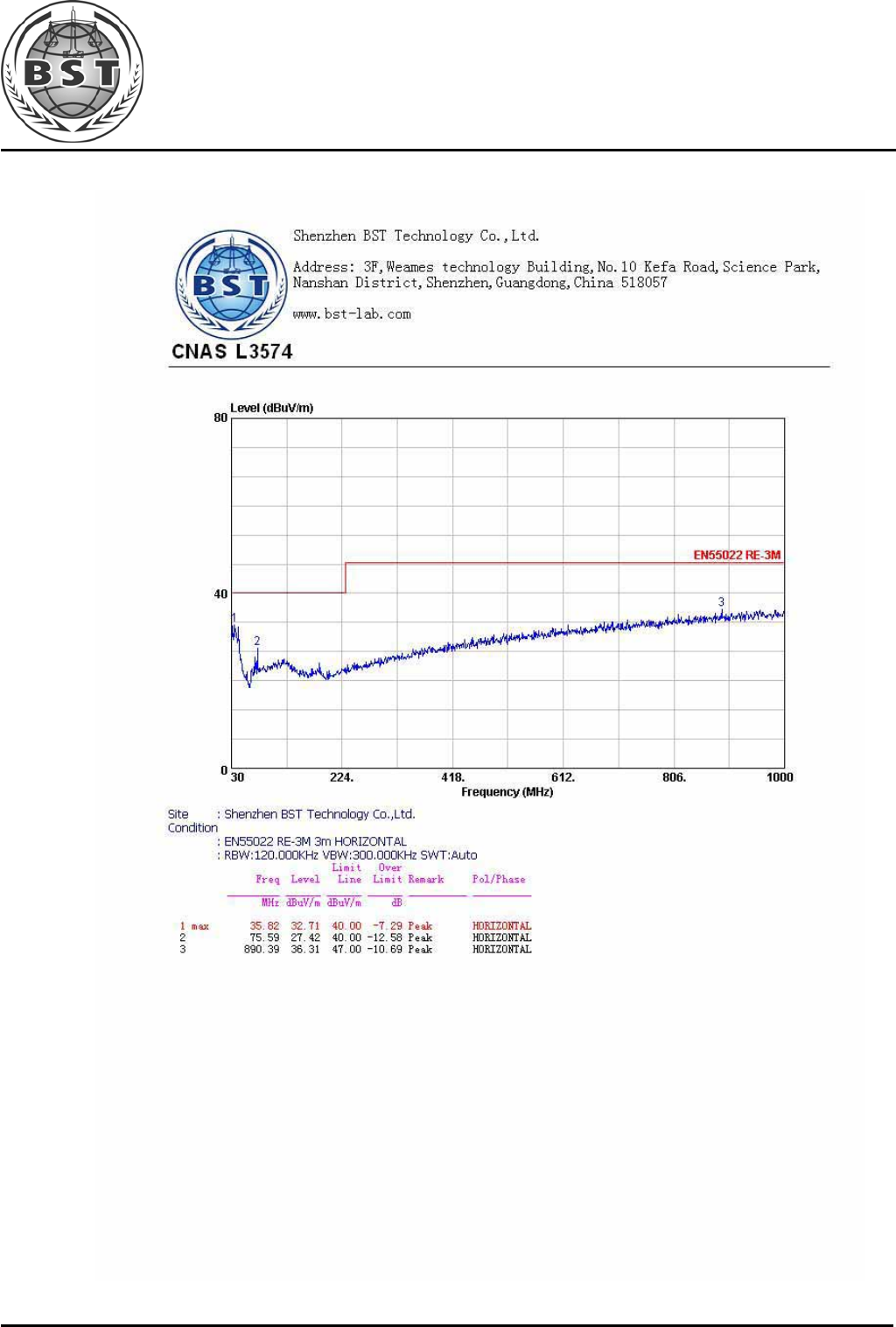
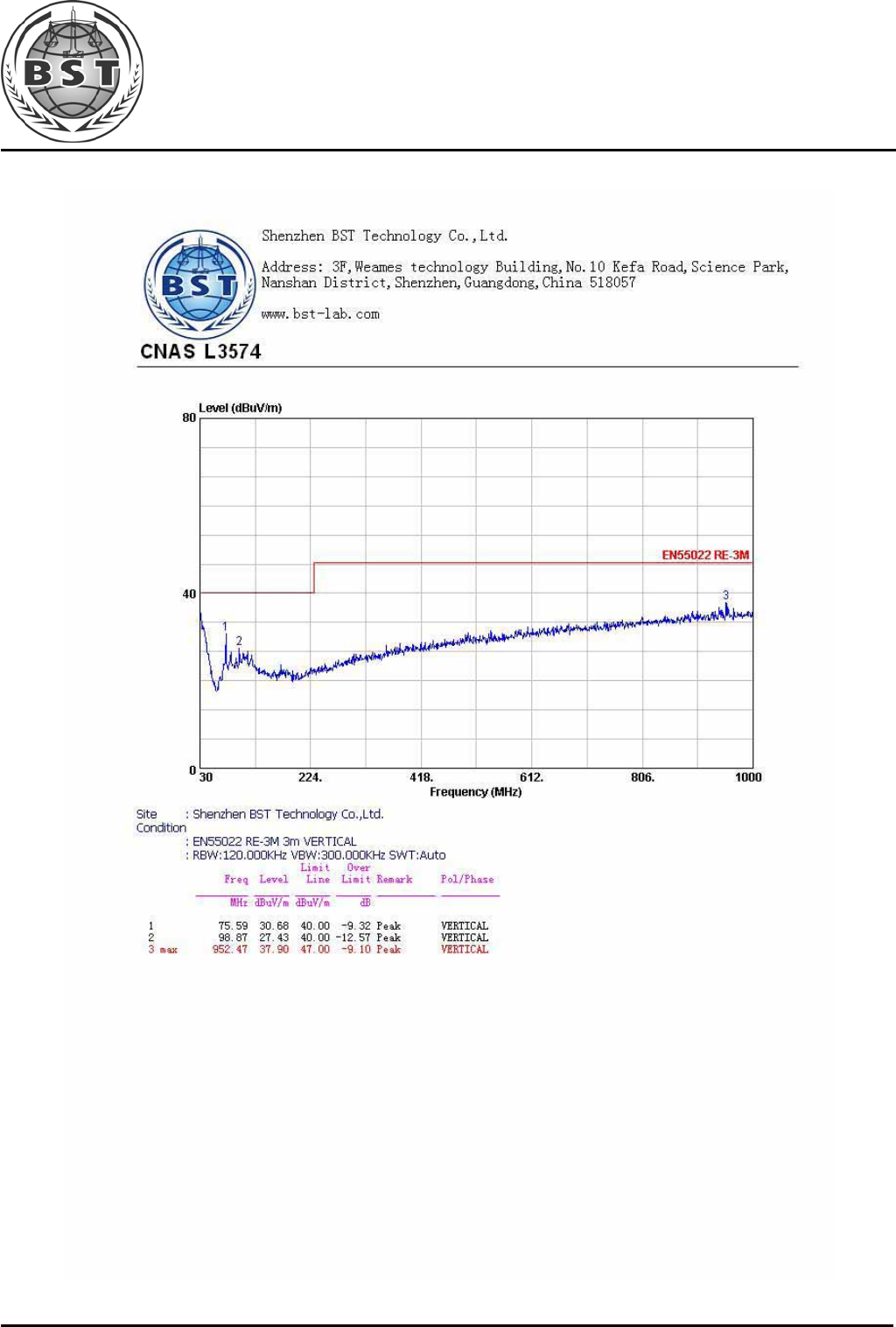
6.7. Test Results
PASS.
Shenzhen BST Technology Co.,Ltd. Report No.: BST09081531321R-1
3F,Weames Technology Building,No. 10 Kefa Road,Science Park,Nanshan District,Shenzhen,Guangdong,China
Tel:86-755- 26747751~3(100 lines) Fax:86-755-26504032 http://www.bst-lab.com
Page 16 of 42
7. HARMONIC CURRENT EMISSION TEST
7.1. Block Diagram of Test Setup
7.2. Test Standard and Limit
7.2.1.Test Standard
EN61000-3-2:2006
7.2.2.Limits
Table 12 Harmonic Current Test Limit (Class A)
Harmonic order
(n) Maximum permissible harmonic current
(A)
Odd harmonics
3 2.30
5 1.14
7 0.77
9 0.40
11 0.33
13 0.21
15≤n≤39 0.15×15/n
Even harmonics
2 1.08
4 0.43
6 0.30
8≤n≤40 0.23×8/n
EUT
AC Mains
Power Analyzer
AC Source

Shenzhen BST Technology Co.,Ltd. Report No.: BST09081531321R-1
3F,Weames Technology Building,No. 10 Kefa Road,Science Park,Nanshan District,Shenzhen,Guangdong,China
Tel:86-755- 26747751~3(100 lines) Fax:86-755-26504032 http://www.bst-lab.com
Page 17 of 42
7.3. Test Procedure
The power cord of the EUT is connected to the output of the test system. Turn on the Power
of the EUT and use the test system to test the harmonic current level.
7.4. Test Results
N/A
Shenzhen BST Technology Co.,Ltd. Report No.: BST09081531321R-1
3F,Weames Technology Building,No. 10 Kefa Road,Science Park,Nanshan District,Shenzhen,Guangdong,China
Tel:86-755- 26747751~3(100 lines) Fax:86-755-26504032 http://www.bst-lab.com
Page 18 of 42
8. VOLTAGE FLUCTUATIONS & FLICKER TEST
8.1. Block Diagram of Test Setup
Same as Section 7.1..
8.2. Test Standard
EN61000-3-3:2008
8.3. Operating Condition of EUT
Same as Section7.3.. The power cord of the EUT is connected to the output of the test system.
Turn on the power of the EUT and use the test system to test the harmonic current level.
Flicker Test Limit
Test items Limits
Pst 1.0
dc 3.3%
dmax 4.0%
dt Not exceed 3.3% for 500ms
8.4. Test Results
N/A
Shenzhen BST Technology Co.,Ltd. Report No.: BST09081531321R-1
3F,Weames Technology Building,No. 10 Kefa Road,Science Park,Nanshan District,Shenzhen,Guangdong,China
Tel:86-755- 26747751~3(100 lines) Fax:86-755-26504032 http://www.bst-lab.com
Page 19 of 42
9. ELECTROSTATIC DISCHARGE TEST
9.1. Block Diagram of ESD Test Setup
9.2. Test Standard
EN 55024:1998+ A2:2003 (EN61000-4-2:1995+A2:2001)
Severity Level 3 for Air Discharge at 8KV
Severity Level 2 for Contact Discharge at 4KV
9.3. Severity Levels and Performance Criterion
9.3.1.Severity level
Level Test Voltage
Contact Discharge (KV) Test Voltage
Air Discharge (KV)
1. 2 2
2. 4 4
3. 6 8
4. 8 15
X. Special Special
9.3.2.Performance criterion: B
9.4. EUT Configuration on Test
The configuration of EUT are listed in Section 3.2.
9.5. Operating Condition of EUT
9.5.1.Setup the EUT as shown in Section 9.1.
9.5.2.Turn on the power of all equipments.
9.5.3.Let the EUT work in test mode (full load) and test it.
Remark: is Discharge Electrode
EUT
AC Mains
AC Mains
ESD
Tester
0.8 m

Shenzhen BST Technology Co.,Ltd. Report No.: BST09081531321R-1
3F,Weames Technology Building,No. 10 Kefa Road,Science Park,Nanshan District,Shenzhen,Guangdong,China
Tel:86-755- 26747751~3(100 lines) Fax:86-755-26504032 http://www.bst-lab.com
Page 20 of 42
9.6. Test Procedure
9.6.1.Air Discharge:
This test is done on a non-conductive surfaces. The round discharge tip of the discharge
electrode shall be approached as fast as possible to touch the EUT.
After each discharge, the discharge electrode shall be removed from the EUT.
The generator is then re-triggered for a new single discharge and repeated 10 times
for each pre-selected test point. This procedure shall be repeated until all the air discharge
completed.
9.6.2.Contact Discharge:
All the procedure shall be same as Section 9.6.1. except that the tip of the discharge electrode
shall touch the EUT before the discharge switch is operated.
9.6.3.Indirect discharge for horizontal coupling plane
At least 20 single discharges shall be applied to the horizontal coupling plane, at points on
each side of the EUT. The discharge electrode positions vertically at a distance of 0.1m from
the EUT and with the discharge electrode touching the coupling plane.
9.6.4.Indirect discharge for vertical coupling plane
At least 20 single discharge shall be applied to the center of one vertical edge of the coupling
plane. The coupling plane, of dimensions 0.5m X 0.5m, is placed parallel to, and positioned
at a distance of 0.1m from the EUT. Discharges shall be applied to the coupling plane, with
this plane in sufficient different positions that the four faces of the EUT are completely
illuminated.
9.7. Test Results
PASS.
Please refer to the following page.
Shenzhen BST Technology Co.,Ltd. Report No.: BST09081531321R-1
3F,Weames Technology Building,No. 10 Kefa Road,Science Park,Nanshan District,Shenzhen,Guangdong,China
Tel:86-755- 26747751~3(100 lines) Fax:86-755-26504032 http://www.bst-lab.com
Page 21 of 42
Electrostatic Discharge Test Results
Shenzhen BST Technology Co., Ltd.
Date :08/20/2009
Applicant : KAIWIN ELECTRONICS CO., LTD Test Date : Aug.20,2009
EUT :
USB Active Cable Temperature : 22
℃
M/N :
KWUU001P Humidity : 50
%
Power Supply : - Test Mode : Full load
Test Engineer : Deng Yong
Air Discharge:
±
8KV For each point positive 10 times and negative 10 times discharge.
Contact Discharge:
±
4KV
Location Kind
A-Air Discharge
C-Contact Discharge
Result
Slots 10 points A PASS
Metal parts 4 points C PASS
Port 2 points C PASS
HCP 8 points C PASS
VCP 8 points C PASS
Discharge should be considered on Contact and Air and Horizontal Coupling Plane (HCP) and Vertical
Coupling Plane (VCP).
Shenzhen BST Technology Co.,Ltd. Report No.: BST09081531321R-1
3F,Weames Technology Building,No. 10 Kefa Road,Science Park,Nanshan District,Shenzhen,Guangdong,China
Tel:86-755- 26747751~3(100 lines) Fax:86-755-26504032 http://www.bst-lab.com
Page 22 of 42
10. RF FIELD STRENGTH SUSCEPTIBILITY TEST
10.1.R/S Test Setup
10.2.Test Standard
EN 55024:1998+ A2:2003 (EN61000-4-3:2006+A1:2008)
Severity Level 2 at 3V / m
10.3.Severity Levels and Performance Criterion
10.3.1.Severity level
Level Field Strength V/m
1. 1
2. 3
3. 10
X. Special
10.3.2.Performance criterion : A
3 Meters
EUT and
Simulators System
0.8 Meter
Anechoic
Chamber
Power Amp Signal
Generator
Measurement
Room

Shenzhen BST Technology Co.,Ltd. Report No.: BST09081531321R-1
3F,Weames Technology Building,No. 10 Kefa Road,Science Park,Nanshan District,Shenzhen,Guangdong,China
Tel:86-755- 26747751~3(100 lines) Fax:86-755-26504032 http://www.bst-lab.com
Page 23 of 42
10.4.EUT Configuration on Test
The configuration of EUT are listed in Section 3.2
10.5.Operating Condition of EUT
Setup the EUT as shown in Section 10.1.. The operating condition of EUT are listed in
section 3.3.
10.6.Test Procedure
The EUT and its simulators are placed on a turn table which is 0.8 meter above the ground.
The EUT is set 3 meters away from the transmitting antenna which is mounted on an antenna
tower. Both horizontal and vertical polarization of the antenna are set on test. Each of the
four sides of EUT must be faced this transmitting antenna and measured individually.
In order to judge the EUT performance, a CCD camera is used to monitor the EUT.
All the scanning conditions are as follows :
Condition of Test Remarks
---------------------------------------------- ----------------------------------
1. Fielded Strength 3 V/m (Severity Level 2)
2. Radiated Signal Modulated
3. Scanning Frequency 80 - 1000 MHz
4. Sweeping time of radiated 0.0015 decade/s
5. Dwell Time 1 Sec.
10.7.Test Results
PASS.
Please refer to the following page.
Shenzhen BST Technology Co.,Ltd. Report No.: BST09081531321R-1
3F,Weames Technology Building,No. 10 Kefa Road,Science Park,Nanshan District,Shenzhen,Guangdong,China
Tel:86-755- 26747751~3(100 lines) Fax:86-755-26504032 http://www.bst-lab.com
Page 24 of 42
RF Field Strength Susceptibility Test Results
Shenzhen BST Technology Co., Ltd.
Date :08/20/2009
Applicant : KAIWIN ELECTRONICS CO., LTD Test Date : Aug.20,2009
EUT : USB Active Cable Temperature : 22
℃
M/N : KWUU001P Humidity : 50
%
Power Supply : - Test Mode : Full load
Test Engineer : Deng Yong Frequency Range : 80 MHz to 1000 MHz
Modulation:
;
AM
Pulse
none 1 KHz 80%
Criterion : A
Frequency Rang : 80-1000
Steps 1% 1%
Horizontal Vertical
Front Pass Pass
Right Pass Pass
Rear Pass Pass
Left Pass Pass
Shenzhen BST Technology Co.,Ltd. Report No.: BST09081531321R-1
3F,Weames Technology Building,No. 10 Kefa Road,Science Park,Nanshan District,Shenzhen,Guangdong,China
Tel:86-755- 26747751~3(100 lines) Fax:86-755-26504032 http://www.bst-lab.com
Page 25 of 42
11. ELECTRICAL FAST TRANSIENT/BURST TEST
11.1.EFT Test Setup
11.2.Test Standard
EN 55024:1998+ A2:2003 (EN61000-4-4:2004)
Severity Level 2 at 1KV
11.3.Severity Levels and Performance Criterion
11.3.1.Severity level
Open Circuit Output Test Voltage ±10%
Level On Power Supply Lines On I/O (Input/Output) Signal
data and control lines
1. 0.5 KV 0.25 KV
2. 1 KV 0.5 KV
3. 2 KV 1 KV
4. 4 KV 2 KV
X Special Special
11.3.2.Performance criterion : B
11.4.EUT Configuration on Test
The configuration of EUT are listed in Section 3.2..
11.5.Operating Condition of EUT
Setup the EUT as shown in Section 11.1.. The operating condition of EUT are listed in
section 3.3.
0.8 m AC Mains
EUT
AC Mains
EFT/B Tester

Shenzhen BST Technology Co.,Ltd. Report No.: BST09081531321R-1
3F,Weames Technology Building,No. 10 Kefa Road,Science Park,Nanshan District,Shenzhen,Guangdong,China
Tel:86-755- 26747751~3(100 lines) Fax:86-755-26504032 http://www.bst-lab.com
Page 26 of 42
11.6.Test Procedure
The EUT is put on the table which is 0.8 meter high above the ground. This reference
ground plane shall project beyond the EUT by at least 0.1m on all sides and the minimum
distance between the EUT and all other conductive structure, except the ground plane
beneath the EUT, shall be more than 0.5m.
11.6.1.For input and output AC power ports:
The EUT is connected to the power mains by using a coupling device which couples the EFT
interference signal to AC power lines. Both polarities of the test voltage should be applied
during compliance test and the duration of the test is 2 mins.
11.6.2.For signal lines and control lines ports:
It’s necessary to test.
11.6.3.For DC output line ports:
It’s unnecessary to test.
11.7.Test Results
N/A
Shenzhen BST Technology Co.,Ltd. Report No.: BST09081531321R-1
3F,Weames Technology Building,No. 10 Kefa Road,Science Park,Nanshan District,Shenzhen,Guangdong,China
Tel:86-755- 26747751~3(100 lines) Fax:86-755-26504032 http://www.bst-lab.com
Page 27 of 42
Electrical Fast Transient/Burst Test Results
Shenzhen BST Technology Co., Ltd.
Date :08/20/2009
Applicant : KAIWIN ELECTRONICS CO., LTD Test Date : Aug.20,2009
EUT : USB Active Cable Temperature : 22
℃
M/N : KWUU001P Humidity : 50
%
Power Supply : - Test Mode : Full load
Test Engineer : Deng Yong
Inject Place : AC Mains
Inject Line Voltage
KV Inject
Time(s) Inject
Method Results Inject
Line Voltag e
KV Inject
Time(s) Inject
Method Results
L ±1 120 Direct --
N ±1 120 Direct --
L N ±1 120 Direct --
Shenzhen BST Technology Co.,Ltd. Report No.: BST09081531321R-1
3F,Weames Technology Building,No. 10 Kefa Road,Science Park,Nanshan District,Shenzhen,Guangdong,China
Tel:86-755- 26747751~3(100 lines) Fax:86-755-26504032 http://www.bst-lab.com
Page 28 of 42
12. SURGE TEST
12.1.Surge Test Setup
12.2.Test Standard
EN 55024:1998+ A2:2003 (EN61000-4-5:2006)
Severity Level 2 for Line to Neutral at 1.0KV
12.3.Severity Levels and Performance Criterion
12.3.1.Severity level
Severity Level Open-Circuit Test Voltage
KV
1
2
3
4
*
0.5
1.0
2.0
4.0
Special
Performance criterion : C
12.4.EUT Configuration on Test
The configuration of EUT are listed in Section 3.2.
12.5.Operating Condition of EUT
12.5.1.Setup the EUT as shown in Section 12.1..
12.5.2.Turn on the power of all equipments.
12.5.3.Let the EUT work in test mode (Full load) and test it.
0.8 m AC Mains
EUT
AC Mains
Test Generator

Shenzhen BST Technology Co.,Ltd. Report No.: BST09081531321R-1
3F,Weames Technology Building,No. 10 Kefa Road,Science Park,Nanshan District,Shenzhen,Guangdong,China
Tel:86-755- 26747751~3(100 lines) Fax:86-755-26504032 http://www.bst-lab.com
Page 29 of 42
12.6.Test Procedure
1) Setup the EUT and test generator as shown on Section 12.1.
2) For line to line coupling mode, provide a 0.5KV 1.2/50us voltage surge (at open-circuit
condition) and 8/20us current surge to EUT selected points.
3) At least 5 positive and 5 negative (polarity) tests with a maximum 1/min repetition rate are
conducted during test.
4) Different phase angles are done individually.
5) Record the EUT operating situation during compliance test and decide the EUT immunity
criterion for above each test.
12.7.Test Results
N/A
Shenzhen BST Technology Co.,Ltd. Report No.: BST09081531321R-1
3F,Weames Technology Building,No. 10 Kefa Road,Science Park,Nanshan District,Shenzhen,Guangdong,China
Tel:86-755- 26747751~3(100 lines) Fax:86-755-26504032 http://www.bst-lab.com
Page 30 of 42
Surge Immunity Test Results
Shenzhen BST Technology Co., Ltd.
Date :08/20/2009
Applicant : KAIWIN ELECTRONICS CO., LTD Test Date : Aug.20,2009
EUT :
USB Active Cable Temperature : 22
℃
M/N : KWUU001P Humidity : 50
%
Power Supply : - Test Mode : Full load
Test Engineer : Deng Yong
Location Polarity Phase
Angle No of Pulse Pulse Voltage (KV)
Result
L-N + 0 5 1.0 --
+ 90 5 1.0 --
+ 180 5 1.0 --
+ 270 5 1.0 --
- 0 5 1.0 --
- 90 5 1.0 --
- 180 5 1.0 --
- 270 5 1.0 --
Shenzhen BST Technology Co.,Ltd. Report No.: BST09081531321R-1
3F,Weames Technology Building,No. 10 Kefa Road,Science Park,Nanshan District,Shenzhen,Guangdong,China
Tel:86-755- 26747751~3(100 lines) Fax:86-755-26504032 http://www.bst-lab.com
Page 31 of 42
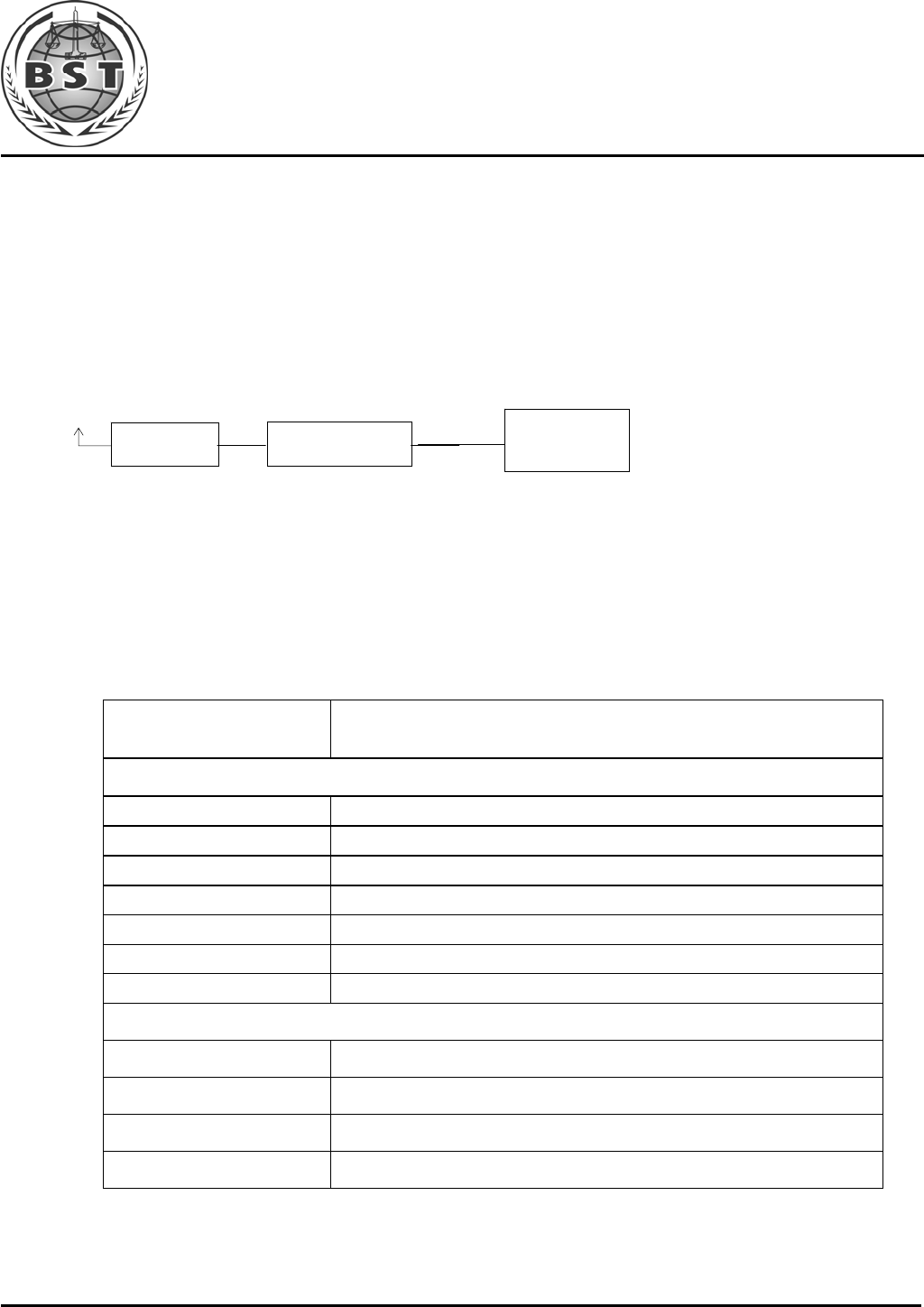
13. INJECTED CURRENTS SUSCEPTIBILITY TEST
13.1.Block Diagram of Test AC Mains Setup
13.2.Test Standard
EN 55024:1998+ A2:2003 (EN61000-4-6:2007)
Severity Level 2 at 3 V (rms), 0.15MHz ~ 80MHz
13.3.Severity Levels and Performance Criterion
13.3.1.Severity level
Level Field Strength V/m
1. 1
2. 3
3. 10
X Special
13.3.2.Performance criterion: A
13.4.EUT Configuration on Test
The configuration of EUT are listed in Section 3.2
13.5.Operating Condition of EUT
Setup the EUT as shown in Section 13.1.. The operating condition of EUT are listed in
section 3.3
Ground Reference Support
EUT
CDN AC Mains
Signal
Generator
Power
Amplifier
Personal Computer Control System
0.1 m

Shenzhen BST Technology Co.,Ltd. Report No.: BST09081531321R-1
3F,Weames Technology Building,No. 10 Kefa Road,Science Park,Nanshan District,Shenzhen,Guangdong,China
Tel:86-755- 26747751~3(100 lines) Fax:86-755-26504032 http://www.bst-lab.com
Page 32 of 42
13.6.Test Procedure
1) Set up the EUT, CDN and test generators as shown on Section 13.1.
2) Let the EUT work in test mode and test it.
3) The EUT are placed on an insulating support 0.8m high above a ground reference plane.
CDN (coupling and decoupling device) is placed on the ground plane about 0.3m from
EUT. Cables between CDN and EUT are as short as possible, and their height above the
ground reference plane shall be between 30 and 50 mm (where possible).
4) The disturbance signal described below is injected to EUT through CDN.
5) The EUT operates within its operational mode(s) under intended climatic conditions after
power on.
6) The frequency range is swept from 150KHz to 80MHz using 3V signal level, and with the
disturbance signal 80% amplitude modulated with a 1KHz sine wave.
7) The rate of sweep shall not exceed 1.5*10-3decades/s. Where the frequency is swept
incrementally, the step size shall not exceed 1% of the start and thereafter 1% of the
preceding frequency value.
8) Recording the EUT operating situation during compliance testing and decide the EUT
immunity criterion.
13.7.Test Results
N/A
Shenzhen BST Technology Co.,Ltd. Report No.: BST09081531321R-1
3F,Weames Technology Building,No. 10 Kefa Road,Science Park,Nanshan District,Shenzhen,Guangdong,China
Tel:86-755- 26747751~3(100 lines) Fax:86-755-26504032 http://www.bst-lab.com
Page 33 of 42
Injected Currents Susceptibility Test Results
Shenzhen BST Technology Co., Ltd.
Date :08/20/2009
Applicant : KAIWIN ELECTRONICS CO., LTD Test Date : Aug.20,2009
EUT :
USB Active Cable Temperature : 22
℃
M/N : KWUU001P Humidity : 50
%
Power Supply : - Test Mode : Full load
Test Engineer : Deng Yong
Frequency Range
(MHz) Injected Position Strength Criterion Result
0.15 ~ 20 AC Line 3V(rms),
Unmodulated A --
20 ~ 80 AC Line 3V(rms),
Unmodulated A --
Shenzhen BST Technology Co.,Ltd. Report No.: BST09081531321R-1
3F,Weames Technology Building,No. 10 Kefa Road,Science Park,Nanshan District,Shenzhen,Guangdong,China
Tel:86-755- 26747751~3(100 lines) Fax:86-755-26504032 http://www.bst-lab.com
Page 34 of 42
14. VOLTAGE DIPS AND INTERRUPTIONS TEST
14.1.Voltage Dips and Interruptions Test Setup
14.2.Test Standard
EN 55024:1998+ A2:2003 (EN61000-4-11:2004)
14.3.Severity Levels and Performance Criterion
14.3.1.Severity level
Test Level
%UT Voltage dip and short
interruptions
%UT
Duration
(in period)
0 100 250p
40 60 5p
70 30 0.5p
14.3.2.Performance criterion : C & B
14.4.EUT Configuration on Test
The configuration of EUT are listed in Section 3.2.
14.5.Operating Condition of EUT
14.5.1.Setup the EUT as shown in Section 14.1.
14.5.2.Turn on the power of all equipments.
14.5.3.Let the EUT work in test mode (SPEAKERS Playing) and test it.
0.8 m
Remark: Combination wave generator and decoupling network are included in test
generator.
AC Mains
EUT
AC Mains
Main Interference
Simulator

Shenzhen BST Technology Co.,Ltd. Report No.: BST09081531321R-1
3F,Weames Technology Building,No. 10 Kefa Road,Science Park,Nanshan District,Shenzhen,Guangdong,China
Tel:86-755- 26747751~3(100 lines) Fax:86-755-26504032 http://www.bst-lab.com
Page 35 of 42
14.6.Test Procedure
1) Set up the EUT and test generator as shown on Section 14.1.
2) The interruptions is introduced at selected phase angles with specified duration.
3) Record any degradation of performance.
14.7.Test Result
N/A
Shenzhen BST Technology Co.,Ltd. Report No.: BST09081531321R-1
3F,Weames Technology Building,No. 10 Kefa Road,Science Park,Nanshan District,Shenzhen,Guangdong,China
Tel:86-755- 26747751~3(100 lines) Fax:86-755-26504032 http://www.bst-lab.com
Page 36 of 42
Voltage Dips And Interruptions Test Results
Shenzhen BST Technology Co., Ltd
Date :08/20/2009
Applicant : KAIWIN ELECTRONICS CO., LTD Test Date : Aug.20,2009
EUT : USB Active Cable Temperature : 22
℃
M/N : KWUU001P Humidity : 50
%
Power Supply : - Test Mode : Full load
Test Engineer : Deng Yong
Test Level
% UT
Voltage Dips &
Short Interruptions
% UT
Duration (in
period) Phase Angle Criterion Result
0 100 250P 0
。
~360
。
C --
40 60 5P 0
。
~360
。
C --
70 30 0.5P 0
。
~360
。
B --

Shenzhen BST Technology Co.,Ltd. Report No.: BST09081531321R-1
3F,Weames Technology Building,No. 10 Kefa Road,Science Park,Nanshan District,Shenzhen,Guangdong,China
Tel:86-755- 26747751~3(100 lines) Fax:86-755-26504032 http://www.bst-lab.com
Page 37 of 42
APPENDIX I
Shenzhen BST Technology Co.,Ltd. Report No.: BST09081531321R-1
3F,Weames Technology Building,No. 10 Kefa Road,Science Park,Nanshan District,Shenzhen,Guangdong,China
Tel:86-755- 26747751~3(100 lines) Fax:86-755-26504032 http://www.bst-lab.com
Page 38 of 42
Shenzhen BST Technology Co.,Ltd. Report No.: BST09081531321R-1
3F,Weames Technology Building,No. 10 Kefa Road,Science Park,Nanshan District,Shenzhen,Guangdong,China
Tel:86-755- 26747751~3(100 lines) Fax:86-755-26504032 http://www.bst-lab.com
Page 39 of 42

Shenzhen BST Technology Co.,Ltd. Report No.: BST09081531321R-1
3F,Weames Technology Building,No. 10 Kefa Road,Science Park,Nanshan District,Shenzhen,Guangdong,China
Tel:86-755- 26747751~3(100 lines) Fax:86-755-26504032 http://www.bst-lab.com
Page 40 of 42
APPENDIX II
Shenzhen BST Technology Co.,Ltd. Report No.: BST09081531321R-1
3F,Weames Technology Building,No. 10 Kefa Road,Science Park,Nanshan District,Shenzhen,Guangdong,China
Tel:86-755- 26747751~3(100 lines) Fax:86-755-26504032 http://www.bst-lab.com
Page 41 of 42
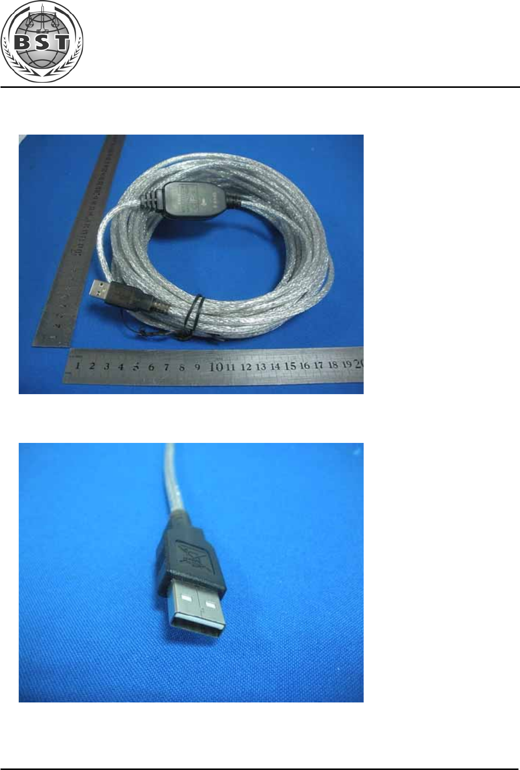
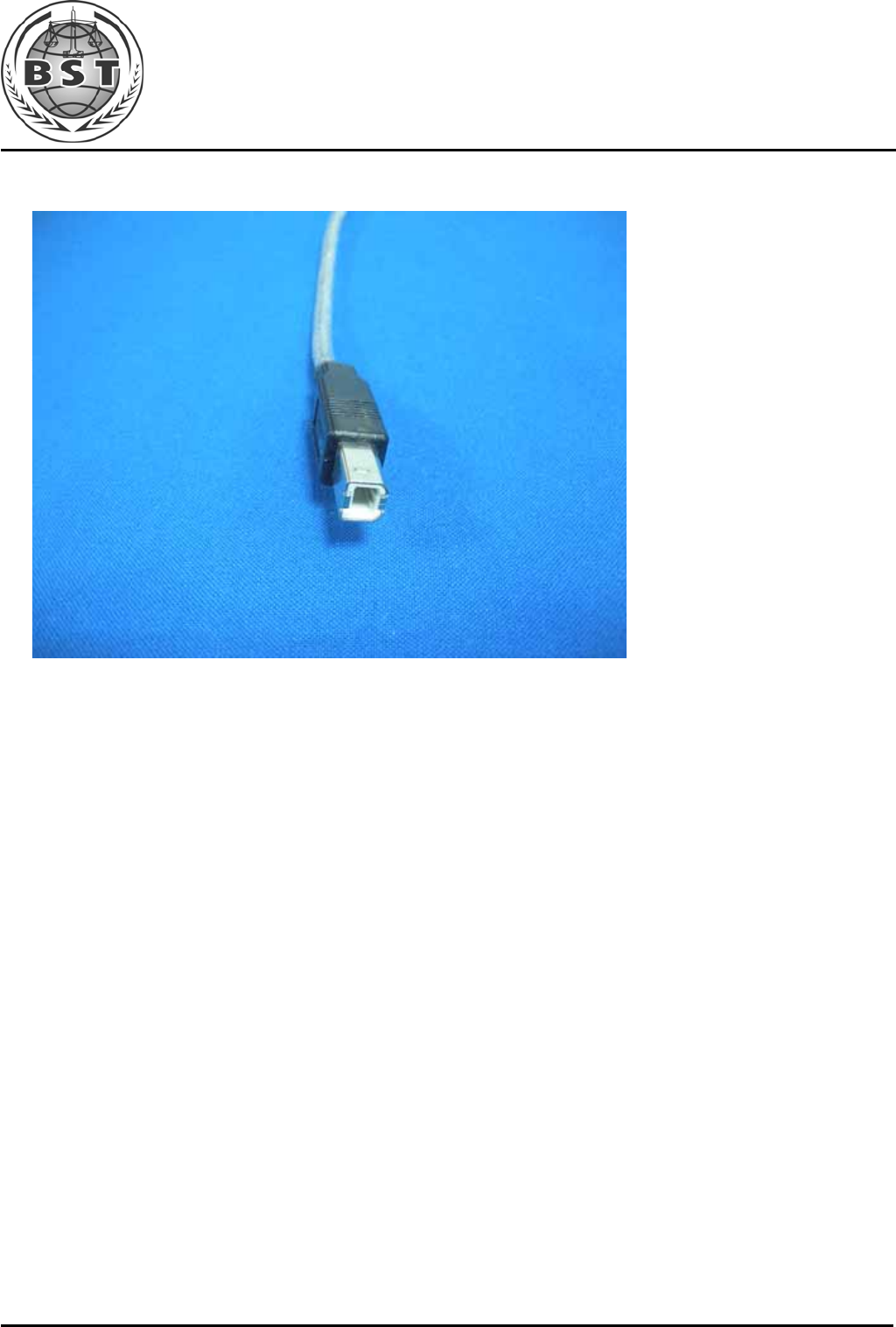
Photo 1 General Appearance of the EUT
Photo 2 General Appearance of the EUT
Shenzhen BST Technology Co.,Ltd. Report No.: BST09081531321R-1
3F,Weames Technology Building,No. 10 Kefa Road,Science Park,Nanshan District,Shenzhen,Guangdong,China
Tel:86-755- 26747751~3(100 lines) Fax:86-755-26504032 http://www.bst-lab.com
Page 42 of 42
Photo 3 General Appearance of the EUT
