Design And Drawing
2017-12-08
: Pdf Design--And-Drawing design--and-drawing uploads
Open the PDF directly: View PDF ![]() .
.
Page Count: 77
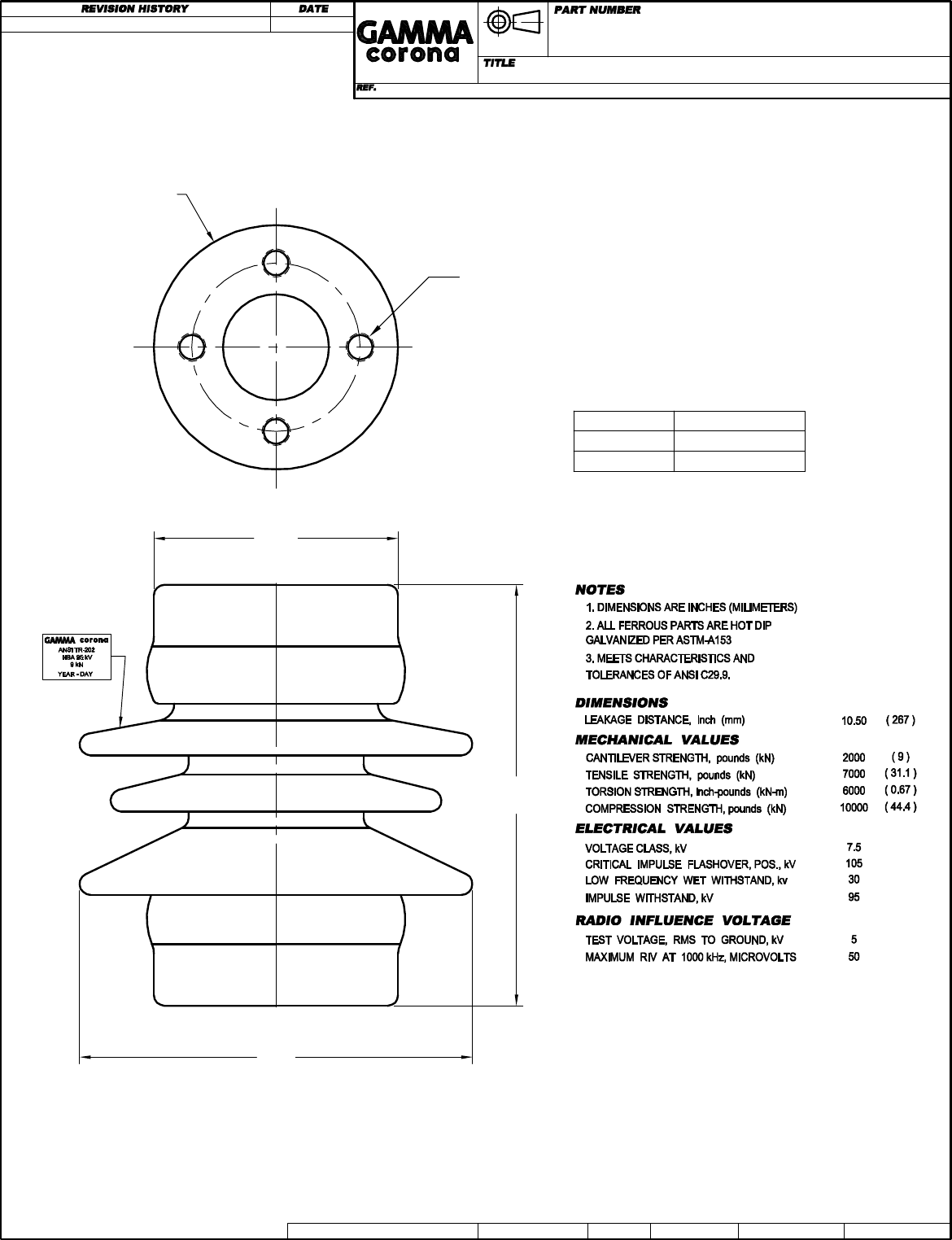
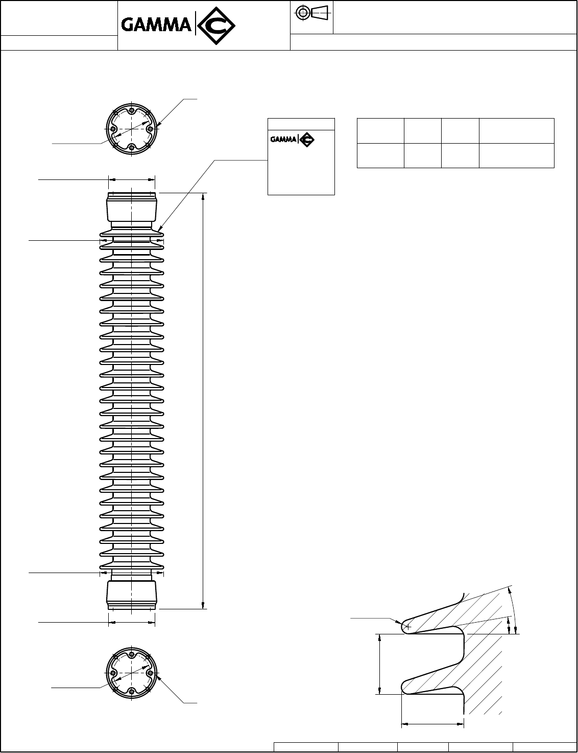
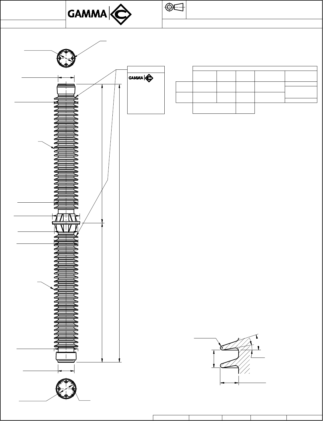
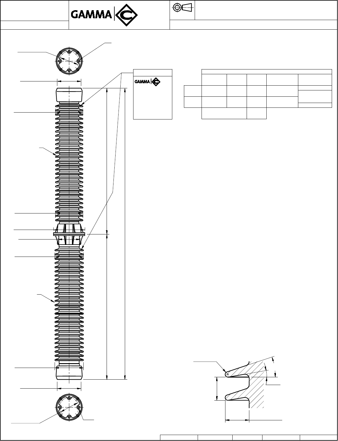
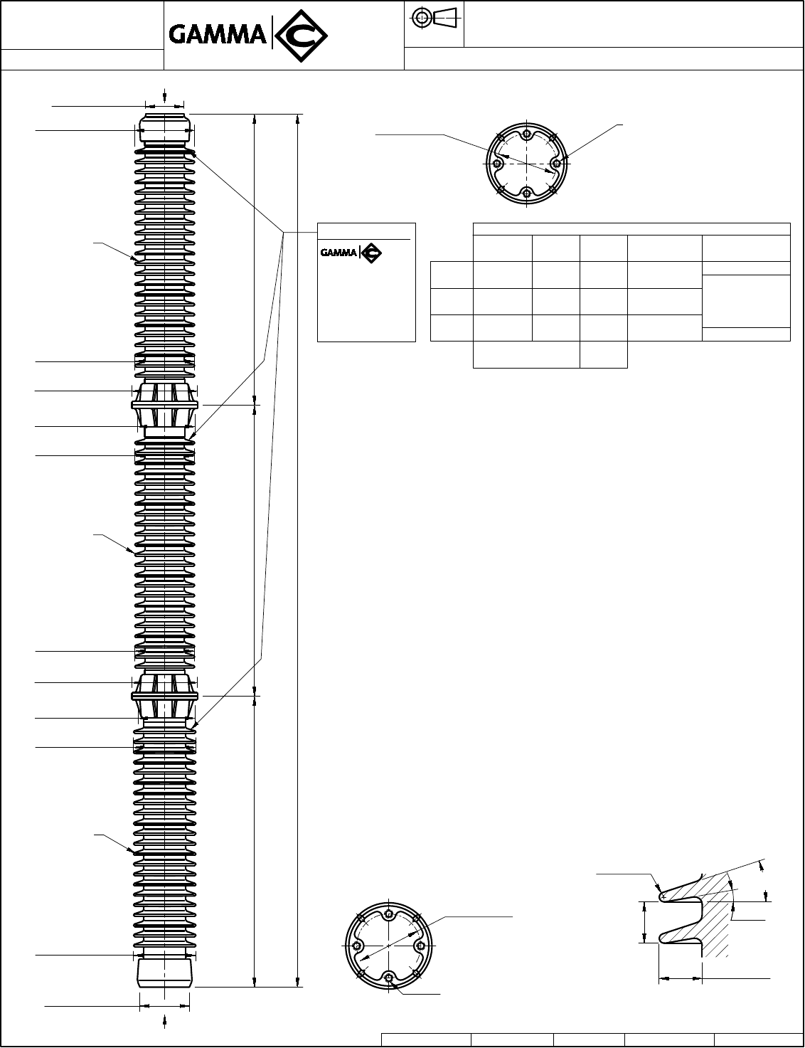
4 TAPPED HOLES Ø1/2"-13+.015 OVERSIZE
.62 (16) MIN. FULL THREAD ON 3.0 (76) B.C.
BOTH ENDS.
DRAWING CREATED 2010-01-15
TR-202
in. (mm)
POST TYPE INSULATOR TR-202
DWG. No. P:8420 /8420-CLIENTE DWG. No.TYPE SALES Autocad 2000 DWN. APP.
8420
L.E. RINCÓN
Reference Color
084201111 LT. GRAY No. 70
084201101 BROWN
A.I.PÉREZ
NOTE: TO PURCHASER
ALL SALES OF GAMMA PRODUCTS ARE
SUBJECT TO OUR STANDARD TERMS
AND CONDITIONS AND THE LIMITED
WARRANTIES THEREUNDER.
Ø4.25
(108)
Ø7.0
(178)
7.5
(191)
MARK
METAL CAP
BOTH ENDS
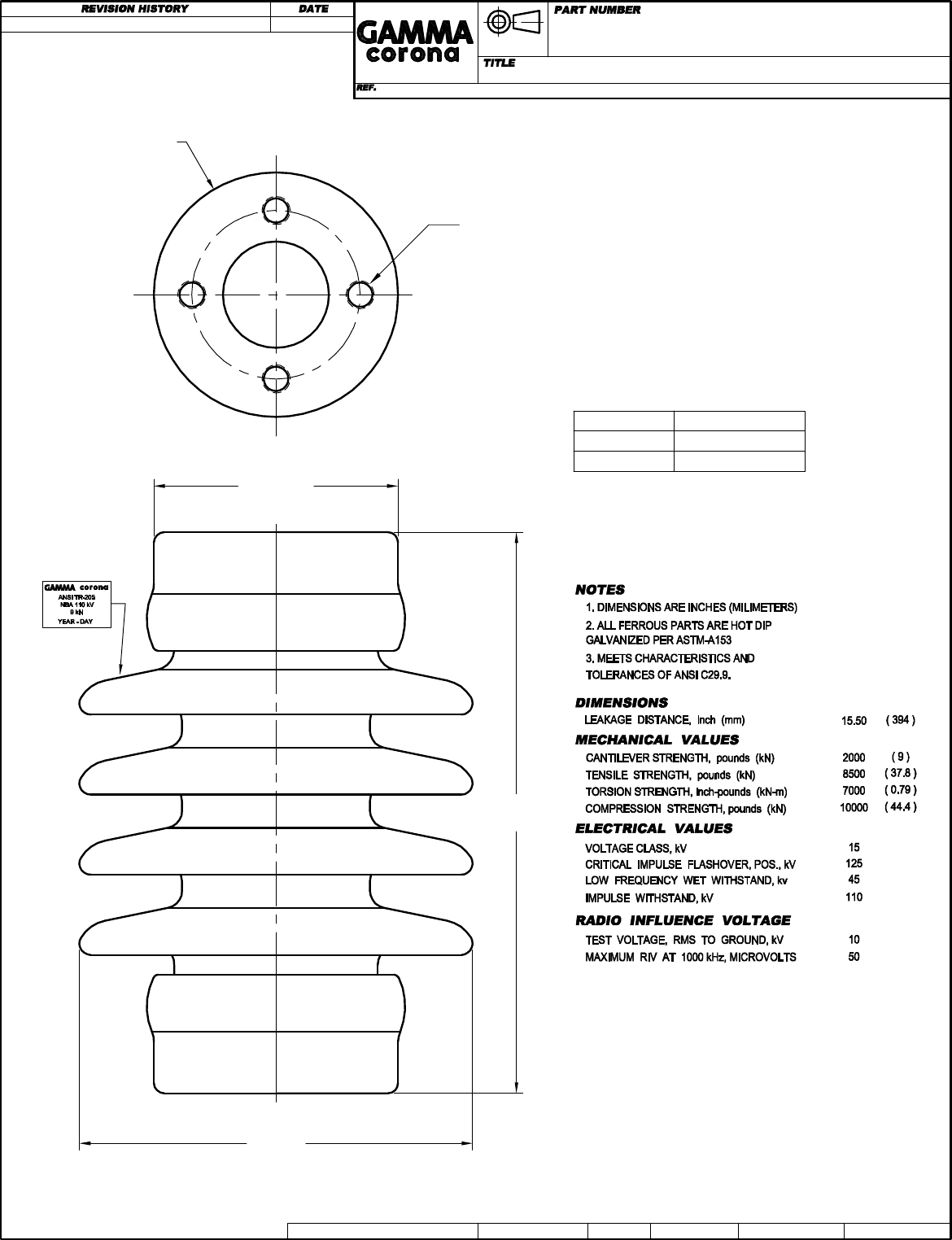
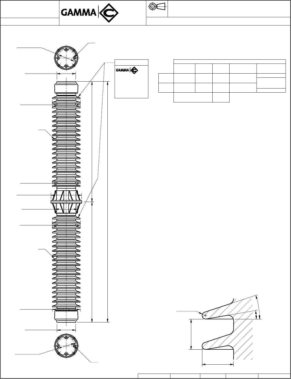
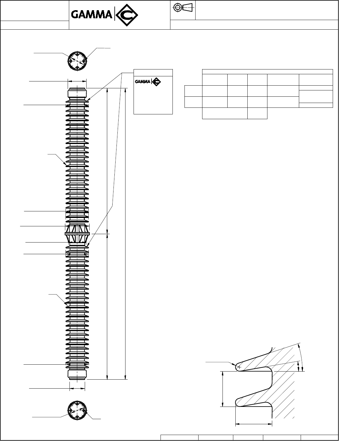
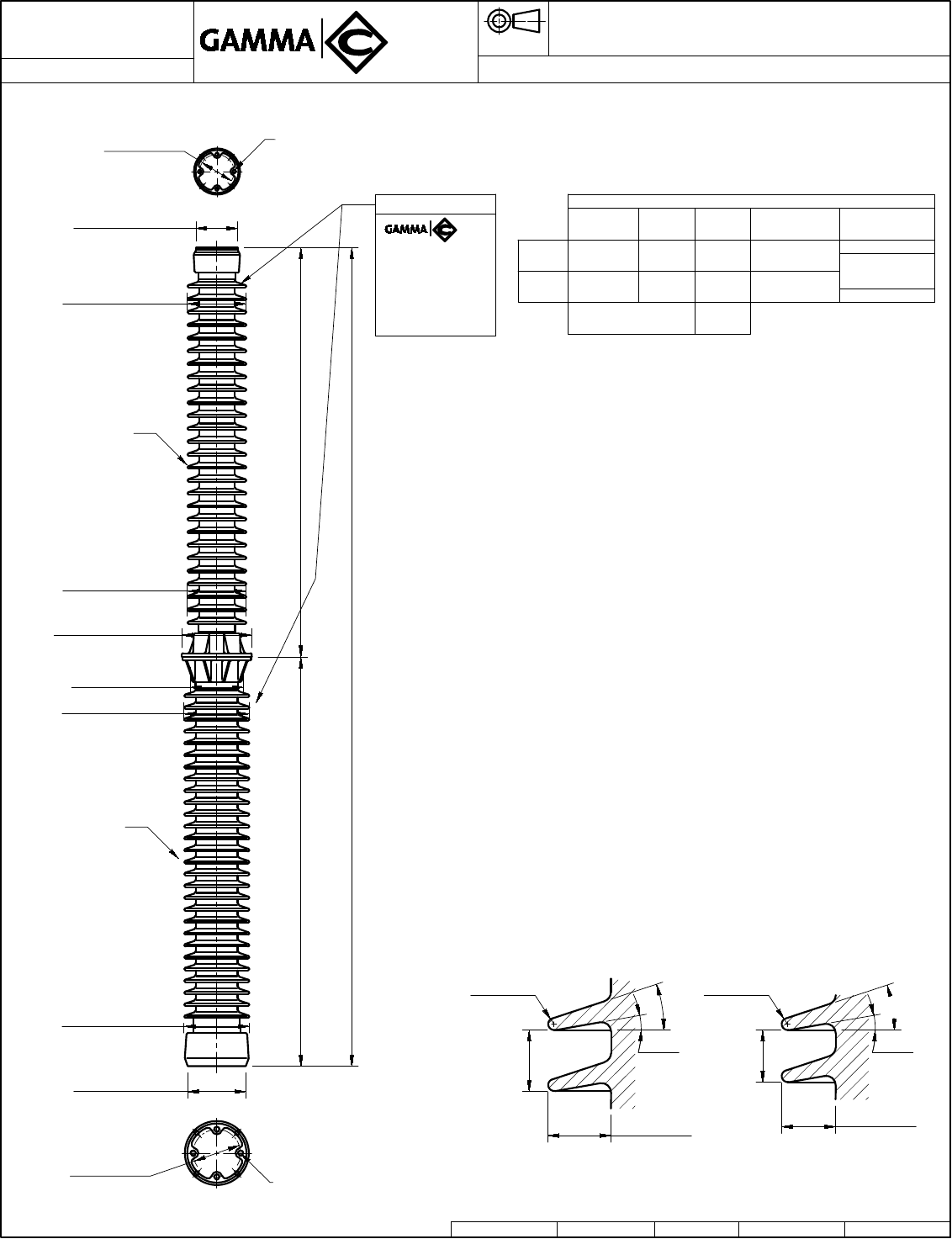
4 TAPPED HOLES Ø1/2"-13+.015 OVERSIZE
.62 (16) MIN. FULL THREAD ON 3.0 (76) B.C.
BOTH ENDS.
DRAWING CREATED 2010-01-14
TR-205
in. (mm)
POST TYPE INSULATOR TR-205
8425
Reference Color
084251111 LT. GRAY No. 70
084251101 BROWN
NOTE: TO PURCHASER
ALL SALES OF GAMMA PRODUCTS ARE
SUBJECT TO OUR STANDARD TERMS
AND CONDITIONS AND THE LIMITED
WARRANTIES THEREUNDER.
Ø4.25 (108)
Ø7 (178)
10.0
(254)
MARK
METAL CAP
BOTH ENDS
DWG. No. P:8425 /8425-CLIENTE DWG. No.TYPE SALES Autocad 2000 DWN. APP.L.E. RINCÓN A.I.PÉREZ
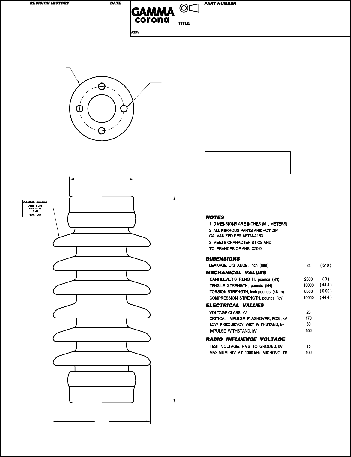
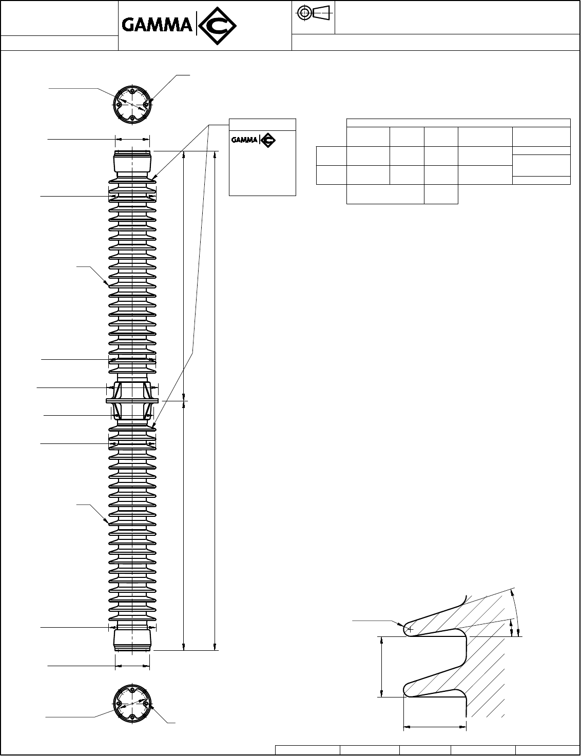
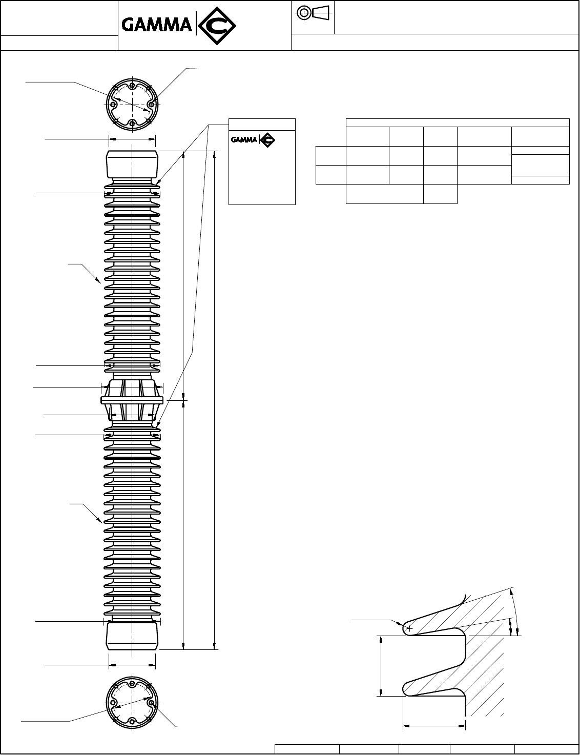
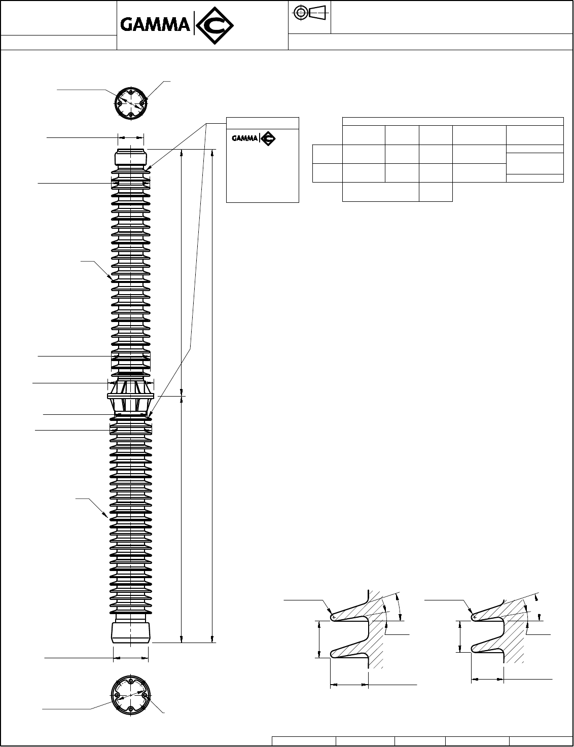
4 TAPPED HOLES Ø1/2"-13+.015 OVERSIZE
.62 (16) MIN. FULL THREAD ON 3.0 (76) B.C.
BOTH ENDS.
DRAWING CREATED 2010-01-14
TR-208
in. (mm)
POST TYPE INSULATOR TR-208
8428
Reference Color
084281111 LT. GRAY No. 70
084281101 BROWN
NOTE: TO PURCHASER
ALL SALES OF GAMMA PRODUCTS ARE
SUBJECT TO OUR STANDARD TERMS
AND CONDITIONS AND THE LIMITED
WARRANTIES THEREUNDER.
Ø4.25
(108)
Ø6.5
(167)
14
(356)
MARK
METAL CAP
BOTH ENDS
DWG. No. P:8428 /8428-CLIENTE DWG. No.TYPE SALES Autocad 2000 DWN. APP.L.E. RINCÓN A.I.PÉREZ
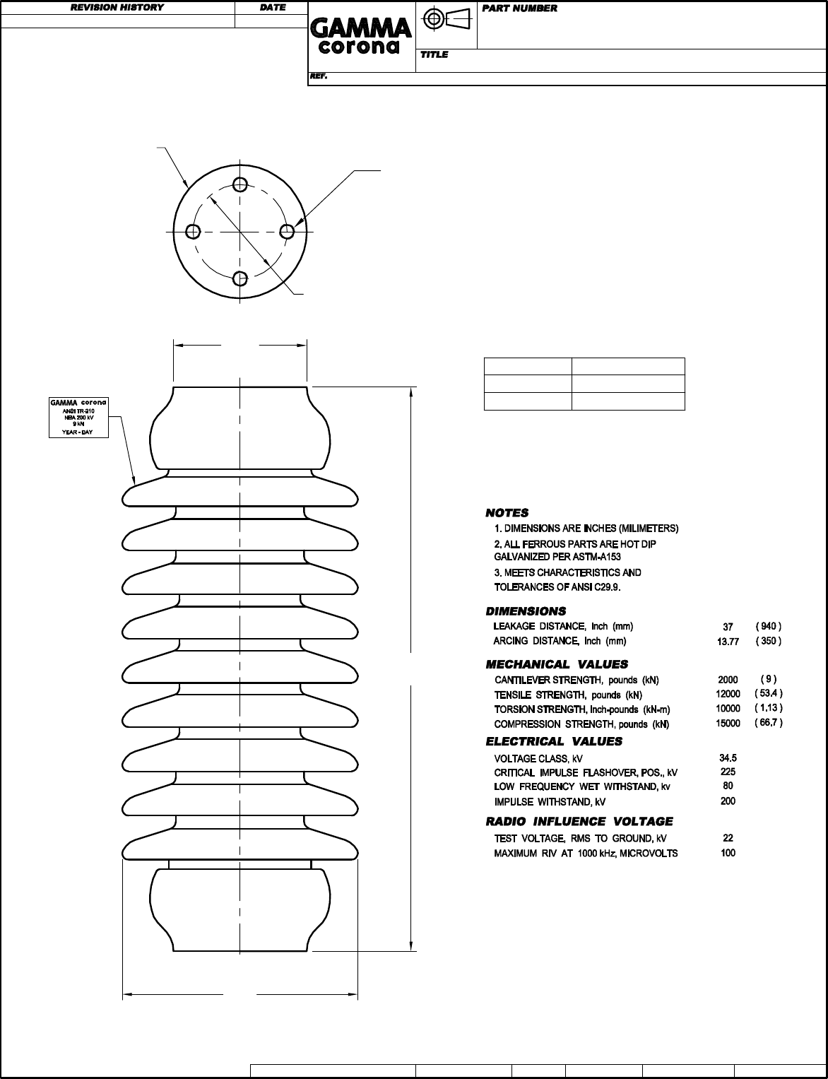
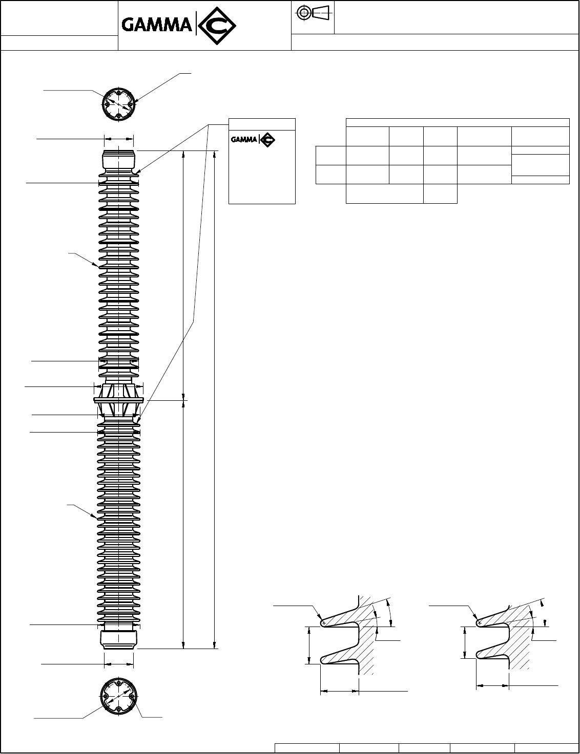
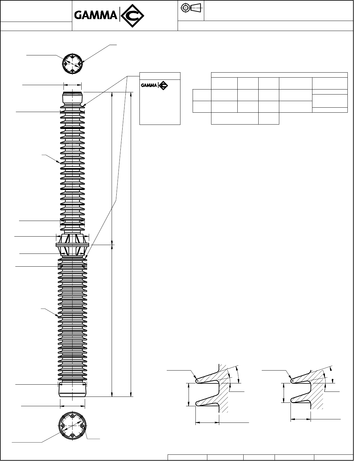
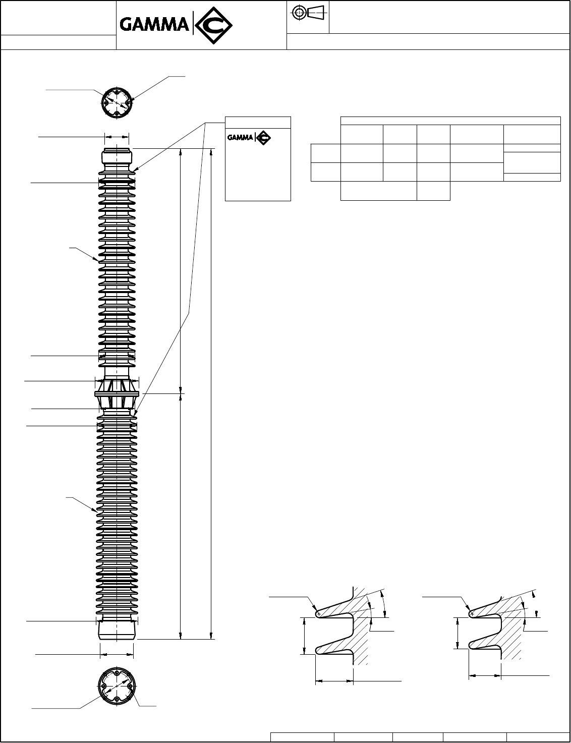
4 TAPPED HOLES Ø1/2"-13+.015 OVERSIZE
.62 (16) MIN. FULL THREAD ON 3.0 (76) B.C.
BOTH ENDS.
DRAWING CREATED 2010-01-14
TR-210
in. (mm)
POST TYPE INSULATOR TR-210
8430
Reference Color
084301111 LT. GRAY No. 70
084301101 BROWN
NOTE: TO PURCHASER
ALL SALES OF GAMMA PRODUCTS ARE
SUBJECT TO OUR STANDARD TERMS
AND CONDITIONS AND THE LIMITED
Ø4.25
(108)
Ø7.5
(191)
18.0
(457)
MARK
METAL CAP
BOTH ENDS
DWG. No. P:8430 /8430-CLIENTE
DWG. No.TYPE SALES
Autocad 2000
DWN.
APP.
L.E. RINCÓN
A.I.PÉREZ
Ø3.0 (76)
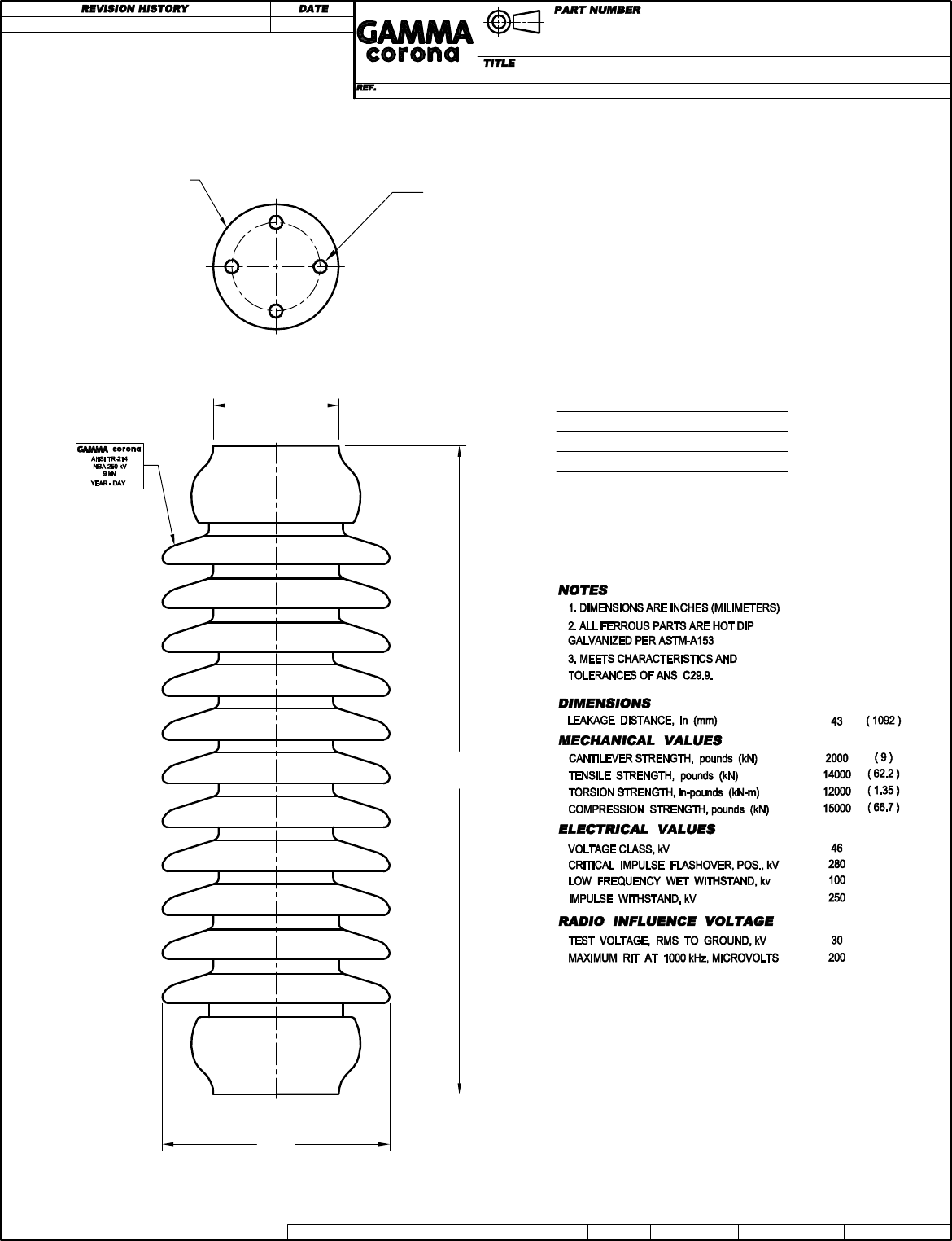
4 TAPPED HOLES Ø1/2"-13+.015 OVERSIZE
.62 (16) MIN. FULL THREAD ON 3.0 (76) B.C.
BOTH ENDS.
DRAWING CREATED 2010-01-14
TR-214
in. (mm)
POST TYPE INSULATOR TR-214
8435
Reference Color
084351111 LT. GRAY No. 70
084351101 BROWN
NOTE: TO PURCHASER
ALL SALES OF GAMMA PRODUCTS ARE
SUBJECT TO OUR STANDARD TERMS
AND CONDITIONS AND THE LIMITED
WARRANTIES THEREUNDER.
Ø4.25
(108)
Ø7.7
(178)
22.0
(559)
MARK
METAL CAP
BOTH ENDS
DWG. No. P:8435 /8435-CLIENTE DWG. No.TYPE SALES Autocad 2000 DWN. APP.L.E. RINCÓN A.I.PÉREZ
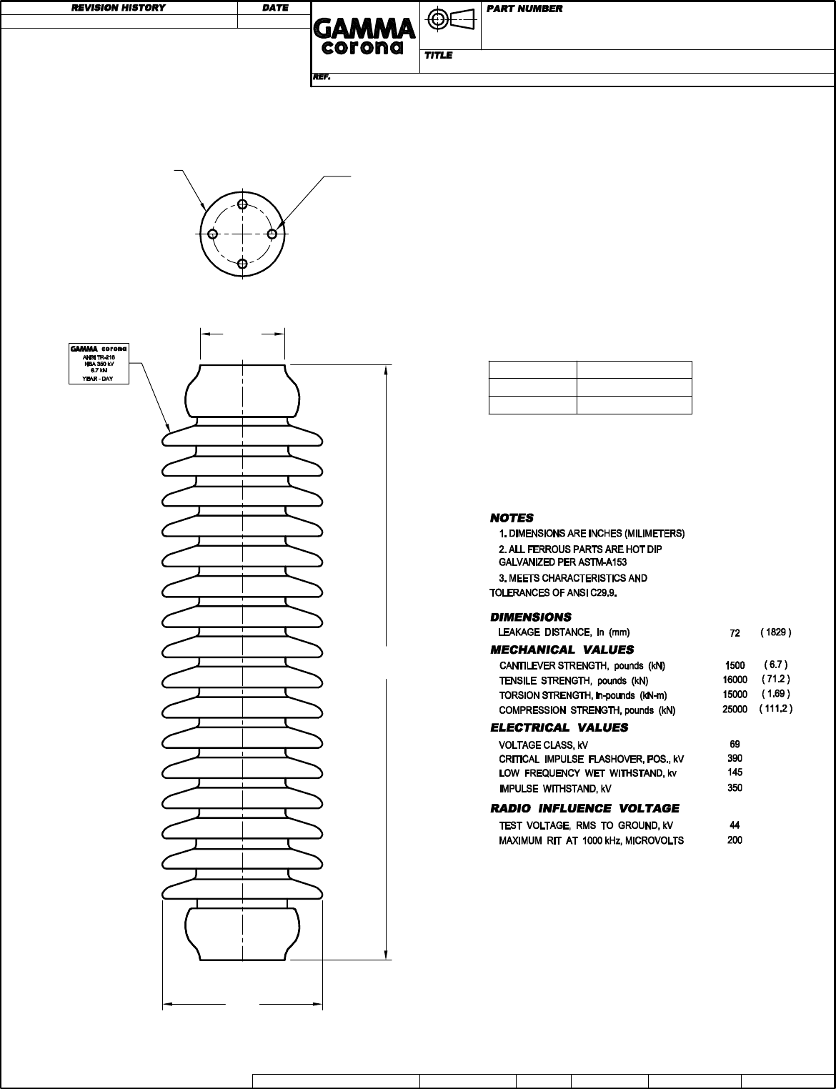
4 TAPPED HOLES Ø1/2"-13+.015 OVERSIZE
.62 (16) MIN. FULL THREAD ON 3.0 (76) B.C.
BOTH ENDS.
DRAWING CREATED 2010-01-15
TR-216
in. (mm)
POST TYPE INSULATOR TR-216
8436
Reference Color
084361111 LT. GRAY No. 70
084361101 BROWN
NOTE: TO PURCHASER
ALL SALES OF GAMMA PRODUCTS ARE
SUBJECT TO OUR STANDARD TERMS
AND CONDITIONS AND THE LIMITED
WARRANTIES THEREUNDER.
Ø4.25
(108)
Ø8.1
(205)
30.0
(762)
MARK
METAL CAP
BOTH ENDS
DWG. No. P:8436 /8436-CLIENTE DWG. No.TYPE SALES Autocad 2000 DWN. APP.L.E. RINCÓN A.I.PÉREZ
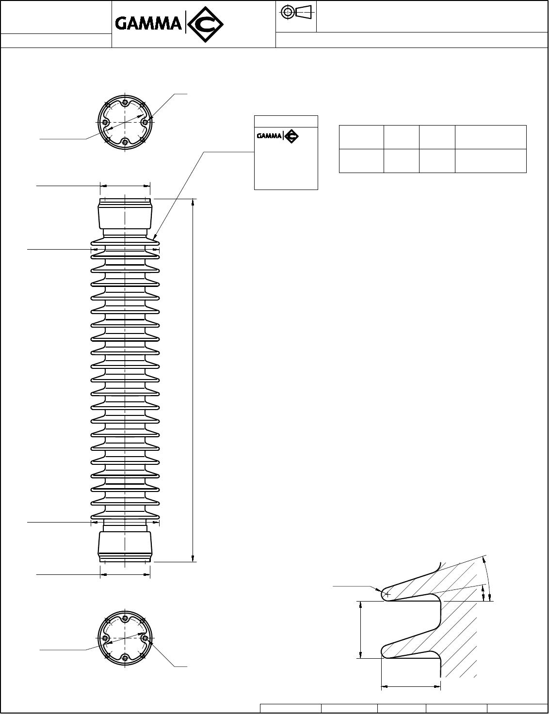
NOTES
1. DIMENSIONS ARE INCHES (MILLIMETERS)
2. ALL FERROUS PARTS ARE HOT DIP GALVANIZED PER ASTM A153, MALLEABLE OR
SPHEROIDAL CAST IRON.
3. MEETS CHARACTERISTICS AND TOLERANCES OF ANSI C29.9 / C29.1
DIMENSIONS
NOMINAL LEAKAGE DISTANCE, In (mm) 101 (2565)
MINIMUM LEAKAGE DISTANCE; In (mm) 99 (2515)
MECHANICAL VALUES
CANTILEVER BREAKING STRENGTH,UPRIGHT pounds (N) 1700 (7562)
CANTILEVER BREAKING STRENGTH,UNDERHUNG pounds (N) 1700 (7562)
TENSILE BREAKING STRENGTH, pounds (N) 20000 (88960)
TORSIONAL BREAKING STRENGTH, in-pounds (N.m) 40000 (4520)
COMPRESSION BREAKING STRENGTH, pounds (N) 60000 (266880)
ELECTRICAL VALUES
GUARANTEED VOLTAGES:
CRITICAL IMPULSE FLASHOVER, POS., kV 610
LOW FREQUENCY WET WITHSTAND, kV 230
IMPULSE WITHSTAND, kV 550
RADIO INFLUENCE VOLTAGE
TEST VOLTAGE, RMS TO GROUND, kV 73
MAXIMUM RIV AT 1 MHz, µV 200
Other characteristics:
Insulating material: Al. Porcelain
Glaze: Light Gray Munsell n° 70
Metal parts assembled with Portland cement.
CERISOL
EUROPE in (mm)
PART NUMBER
TITLE STATION POST INSULATOR. STANDARD STRENGTH
286SU0550
DWG. No.: H21286EJ DWG: TYPE SALES Date: 2015/07/01 DWN: A.MEJÍA A. APP: C. JARAMILLO
TR 286
Technical reference number:
BIL 550 kV
NO T E : TO PURCHASER ALL SALES OF
GAMMA PRODUCTS ARE SUBJECT TO
O U R S T A N D A R D T E R M S A N D
C O ND I T I O N S A N D T H E L IM I T ED
W A R R A N T I E S T H E R E U N D E R
Ø8.46 (Ø215)
Ø8.46 (Ø215)
Ø6.22 (Ø158)
(21 Sheds) 45.0 ±0.06 (1143 ±1.6)
Ø6.22 (Ø158)
Bottom Flange View
4 Tapped Holes 5/8-11 UNC
+0.015 Oversize
Full Thread 0.87 (22)
Top Flange View 4 Tapped Holes 5/8-11 UNC
+0.015 Oversize
Full Thread 0.87 (22)
Ø5.0 (Ø127)
Ø5.0 (Ø127)
Shed Profile
1.69 (43)
R 0.19 (5)
1.77 (45)
10°
18°
Unit
Part n°
Unit
Shed ID Weight: Fixation:
Top / Bottom
S2907EJ TR286
SC907
143 lb
65 kg 4 holes 5/8-11UNC
4 holes 5/8-11UNC
Marks
CERISOL
EUROPE
Year-month
Serial number
286SU0550
TR286
SC907

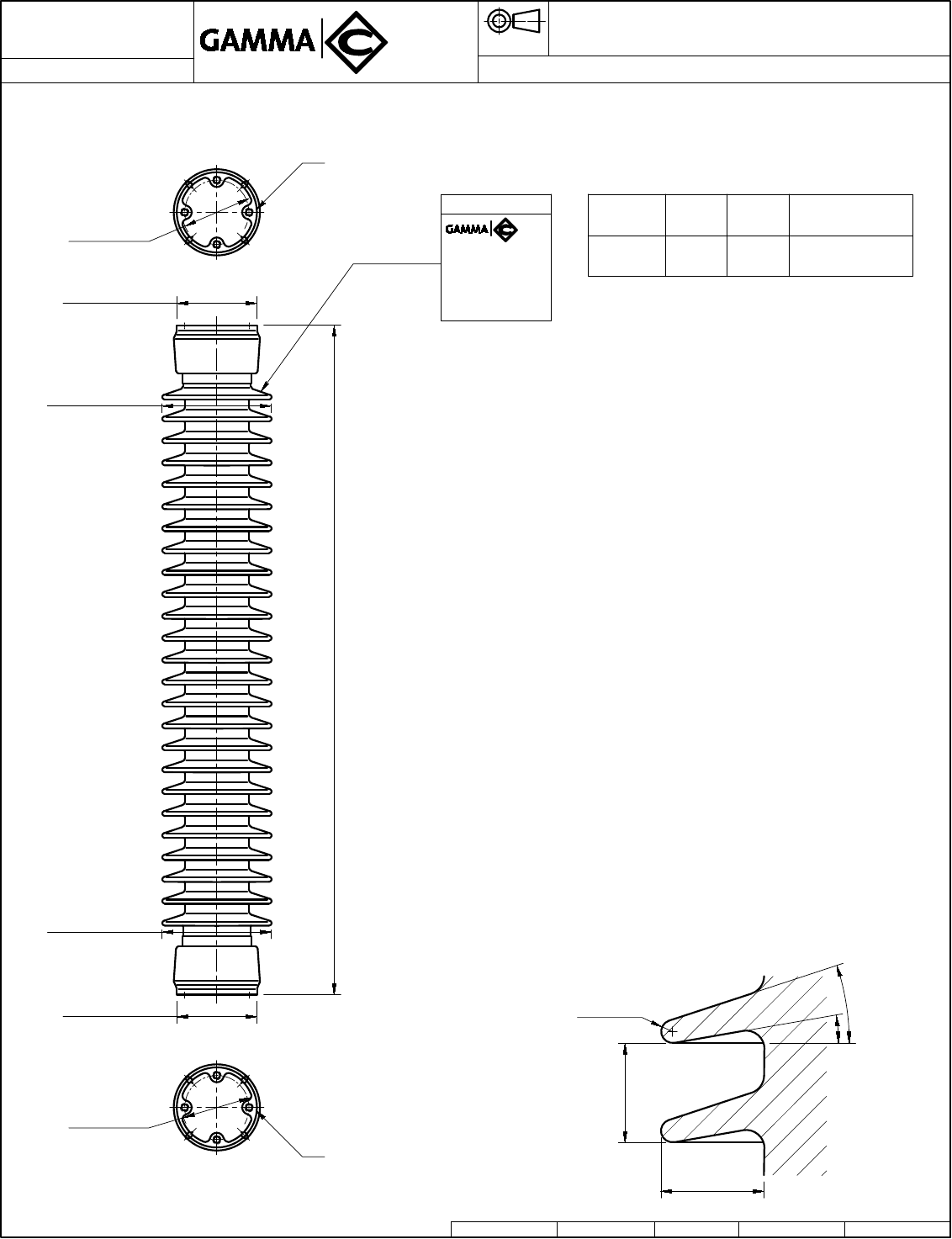
NOTES
1. DIMENSIONS ARE INCHES (MILLIMETERS)
2. ALL FERROUS PARTS ARE HOT DIP GALVANIZED PER ASTM A153, MALLEABLE OR
SPHEROIDAL CAST IRON.
3. MEETS CHARACTERISTICS AND TOLERANCES OF ANSI C29.9 / C29.1
DIMENSIONS
NOMINAL LEAKAGE DISTANCE, In (mm) 101 (2565)
MINIMUM LEAKAGE DISTANCE; In (mm) 99 (2515)
MECHANICAL VALUES
CANTILEVER BREAKING STRENGTH,UPRIGHT pounds (N) 2600 (11565)
CANTILEVER BREAKING STRENGTH,UNDERHUNG pounds (N) 2600 (11565)
TENSILE BREAKING STRENGTH, pounds (N) 25000 (112000)
TORSIONAL BREAKING STRENGTH, in-pounds (N.m) 90000 (10170)
COMPRESSION BREAKING STRENGTH, pounds (N) 75000 (333600)
ELECTRICAL VALUES
GUARANTEED VOLTAGES:
CRITICAL IMPULSE FLASHOVER, POS., kV 610
LOW FREQUENCY WET WITHSTAND, kV 230
IMPULSE WITHSTAND, kV 550
RADIO INFLUENCE VOLTAGE
TEST VOLTAGE, RMS TO GROUND, kV 73
MAXIMUM RIV AT 1 MHz, µV 200
Other characteristics:
Insulating material: Al. Porcelain
Glaze: Light Gray Munsell n° 70
Metal parts assembled with Portland cement.
CERISOL
EUROPE in (mm)
PART NUMBER
TITLE STATION POST INSULATOR. HIGH STRENGTH
287HU0550
DWG. No.: H21287EJ DWG: TYPE SALES Date: 2015/07/01 DWN: A.MEJÍA A. APP: C. JARAMILLO
TR 287
Technical reference number:
BIL 550 kV
NO T E : TO PURCHASER ALL SALES OF
GAMMA PRODUCTS ARE SUBJECT TO
O U R S T A N D A R D T E R M S A N D
C O ND I T I O N S A N D T H E L IM I T ED
W A R R A N T I E S T H E R E U N D E R
Bottom Flange View
4 Tapped Holes 5/8-11 UNC
+0.015 Oversize
Full Thread 0.87 (22)
Top Flange View 4 Tapped Holes 5/8-11 UNC
+0.015 Oversize
Full Thread 0.87 (22)
Marks
CERISOL
EUROPE
Year-month
Serial number
287HU0550
TR287
SC914
Unit
Part n°
Unit
Shed ID Weight: Fixation:
Top / Bottom
S2914EJ TR287
SC914
172 lb
78 kg 4 holes 5/8-11UNC
4 holes 5/8-11UNC
Shed Profile
1.69 (43)
R 0.19 (5)
1.77 (45)
10°
18°
Ø9.41 (Ø239)
Ø9.41 (Ø239)
Ø6.3 (Ø160)
(21 Sheds) 45.0 ±0.06 (1143 ±1.6)
Ø6.3 (Ø160)
Ø5.0 (Ø127)
Ø5.0 (Ø127)
NOTES
1. DIMENSIONS ARE INCHES (MILLIMETERS)
2. ALL FERROUS PARTS ARE HOT DIP GALVANIZED PER ASTM A153, MALLEABLE OR
SPHEROIDAL CAST IRON.
3. MEETS CHARACTERISTICS AND TOLERANCES OF ANSI C29.9 / C29.1
DIMENSIONS
NOMINAL LEAKAGE DISTANCE, In (mm) 121 (3073)
MINIMUM LEAKAGE DISTANCE; In (mm) 116 (2946)
MECHANICAL VALUES
CANTILEVER BREAKING STRENGTH,UPRIGHT pounds (N) 1400 (6227)
CANTILEVER BREAKING STRENGTH,UNDERHUNG pounds (N) 1400 (6227)
TENSILE BREAKING STRENGTH, pounds (N) 20000 (88960)
TORSIONAL BREAKING STRENGTH, in-pounds (N.m) 40000 (4520)
COMPRESSION BREAKING STRENGTH, pounds (N) 60000 (266880)
ELECTRICAL VALUES
GUARANTEED VOLTAGES:
CRITICAL IMPULSE FLASHOVER, POS., kV 710
LOW FREQUENCY WET WITHSTAND, kV 275
IMPULSE WITHSTAND, kV 650
RADIO INFLUENCE VOLTAGE
TEST VOLTAGE, RMS TO GROUND, kV 88
MAXIMUM RIV AT 1 MHz, µV 200
Other characteristics:
Insulating material: Al. Porcelain
Glaze: Light Gray Munsell n° 70
Metal parts assembled with Portland cement.
CERISOL
EUROPE in (mm)
PART NUMBER
TITLE STATION POST INSULATOR. STANDARD STRENGTH
288SU0650
DWG. No.: H21288EJ DWG: TYPE SALES Date: 2015/07/01 DWN: A.MEJÍA A. APP: C. JARAMILLO
TR 288
Technical reference number:
BIL 650 kV
NO T E : TO PURCHASER ALL SALES OF
GAMMA PRODUCTS ARE SUBJECT TO
O U R S T A N D A R D T E R M S A N D
C O ND I T I O N S A N D T H E L IM I T ED
W A R R A N T I E S T H E R E U N D E R
Bottom Flange View
4 Tapped Holes 5/8-11 UNC
+0.015 Oversize
Full Thread 0.87 (22)
Top Flange View 4 Tapped Holes 5/8-11 UNC
+0.015 Oversize
Full Thread 0.87 (22)
Marks
CERISOL
EUROPE
Year-month
Serial number
288SU0650
TR288
SC6905
Unit
Part n°
Unit
Shed ID Weight: Fixation:
Top / Bottom
S26905EJ TR288
SC6905
159 lb
72 kg 4 holes 5/8-11UNC
4 holes 5/8-11UNC
Shed Profile
1.77 (45)
R 0.19 (5)
1.77 (45)
10°
18°
Ø8.46 (Ø215)
Ø6.22 (Ø158)
(25 Sheds) 54.0 ±0.06 (1372 ±1.6)
Ø6.22 (Ø158)
Ø8.46 (Ø215)
Ø5.0 (Ø127)
Ø5.0 (Ø127)

NOTES
1. DIMENSIONS ARE INCHES (MILLIMETERS)
2. ALL FERROUS PARTS ARE HOT DIP GALVANIZED PER ASTM A153, MALLEABLE OR
SPHEROIDAL CAST IRON.
3. MEETS CHARACTERISTICS AND TOLERANCES OF ANSI C29.9 / C29.1
DIMENSIONS
NOMINAL LEAKAGE DISTANCE, In (mm) 121 (3073)
MINIMUM LEAKAGE DISTANCE; In (mm) 116 (2946)
MECHANICAL VALUES
CANTILEVER BREAKING STRENGTH,UPRIGHT pounds (N) 2200 (9786)
CANTILEVER BREAKING STRENGTH,UNDERHUNG pounds (N) 2200 (9786)
TENSILE BREAKING STRENGTH, pounds (N) 25000 (88960)
TORSIONAL BREAKING STRENGTH, in-pounds (N.m) 90000 (10170)
COMPRESSION BREAKING STRENGTH, pounds (N) 75000 (333600)
ELECTRICAL VALUES
GUARANTEED VOLTAGES:
CRITICAL IMPULSE FLASHOVER, POS., kV 710
LOW FREQUENCY WET WITHSTAND, kV 275
IMPULSE WITHSTAND, kV 650
RADIO INFLUENCE VOLTAGE
TEST VOLTAGE, RMS TO GROUND, kV 88
MAXIMUM RIV AT 1 MHz, µV 200
Other characteristics:
Insulating material: Al. Porcelain
Glaze: Light Gray Munsell n° 70
Metal parts assembled with Portland cement.
CERISOL
EUROPE in (mm)
PART NUMBER
TITLE STATION POST INSULATOR. HIGH STRENGTH
289HU0650
DWG. No.: H21289EJ DWG: TYPE SALES Date: 2015/07/01 DWN: A.MEJÍA A. APP: C. JARAMILLO
TR 289
Technical reference number:
BIL 650 kV
NO T E : TO PURCHASER ALL SALES OF
GAMMA PRODUCTS ARE SUBJECT TO
O U R S T A N D A R D T E R M S A N D
C O ND I T I O N S A N D T H E L IM I T ED
W A R R A N T I E S T H E R E U N D E R
Bottom Flange View
4 Tapped Holes 5/8-11 UNC
+0.015 Oversize
Full Thread 0.87 (22)
Top Flange View 4 Tapped Holes 5/8-11 UNC
+0.015 Oversize
Full Thread 0.87 (22)
Marks
CERISOL
EUROPE
Year-month
Serial number
289HU0650
TR289
SC913
Unit
Part n°
Unit
Shed ID Weight: Fixation:
Top / Bottom
S2913EJ TR289
SC913
201 lb
91 kg 4 holes 5/8-11UNC
4 holes 5/8-11UNC
Shed Profile
1.77 (45)
R 0.19 (5)
1.77 (45)
10°
18°
Ø9.06 (Ø230)
Ø6.3 (Ø160)
(25 Sheds) 54.0 ±0.06 (1372 ±1.6)
Ø6.3 (Ø160)
Ø9.06 (Ø230)
Ø5.0 (Ø127)
Ø5.0 (Ø127)
NOTES
1. DIMENSIONS ARE INCHES (MILLIMETERS)
2. ALL FERROUS PARTS ARE HOT DIP GALVANIZED PER ASTM A153, MALLEABLE OR
SPHEROIDAL CAST IRON.
3. MEETS CHARACTERISTICS AND TOLERANCES OF ANSI C29.9 / C29.1
DIMENSIONS
NOMINAL LEAKAGE DISTANCE, In (mm) 134 (3404)
MINIMUM LEAKAGE DISTANCE; In (mm) 132 (3353)
MECHANICAL VALUES
CANTILEVER BREAKING STRENGTH,UPRIGHT pounds (N) 1200 (5338)
CANTILEVER BREAKING STRENGTH,UNDERHUNG pounds (N) 1200 (5338)
TENSILE BREAKING STRENGTH, pounds (N) 20000 (88960)
TORSIONAL BREAKING STRENGTH, in-pounds (N.m) 40000 (4520)
COMPRESSION BREAKING STRENGTH, pounds (N) 60000 (266880)
ELECTRICAL VALUES
GUARANTEED VOLTAGES:
CRITICAL IMPULSE FLASHOVER, POS., kV 810
LOW FREQUENCY WET WITHSTAND, kV 315
IMPULSE WITHSTAND, kV 750
RADIO INFLUENCE VOLTAGE
TEST VOLTAGE, RMS TO GROUND, kV 103
MAXIMUM RIV AT 1 MHz, µV 500
Other characteristics:
Insulating material: Al. Porcelain
Glaze: Light Gray Munsell n° 70
Metal parts assembled with Portland cement.
CERISOL
EUROPE in (mm)
PART NUMBER
TITLE STATION POST INSULATOR. STANDARD STRENGTH
291SU0750
DWG. No.: H21291EJ DWG: TYPE SALES Date: 2015/07/01 DWN: A.MEJÍA A. APP: C. JARAMILLO
TR 291
Technical reference number:
BIL 750 kV
NO T E : TO PURCHASER ALL SALES OF
GAMMA PRODUCTS ARE SUBJECT TO
O U R S T A N D A R D T E R M S A N D
C O ND I T I O N S A N D T H E L IM I T ED
W A R R A N T I E S T H E R E U N D E R
Bottom Flange View
4 Tapped Holes 5/8-11 UNC
+0.015 Oversize
Full Thread 0.87 (22)
Top Flange View 4 Tapped Holes 5/8-11 UNC
+0.015 Oversize
Full Thread 0.87 (22)
Marks
CERISOL
EUROPE
Year-month
Serial number
291SU0750
TR291
SC911
Unit
Part n°
Unit
Shed ID Weight: Fixation:
Top / Bottom
S2911EJ TR291
SC911
185 lb
84 kg 4 holes 5/8-11UNC
4 holes 5/8-11UNC
Shed Profile
1.92 (49)
R 0.19 (5)
1.77 (45)
10°
18°
Ø5.0 (Ø127)
Ø5.0 (Ø127)
Ø8.78 (Ø223)
Ø6.22 (Ø158)
(27 Sheds) 62.0 ±0.09 (1575 ±2.4)
Ø6.22 (Ø158)
Ø8.78 (Ø223)

NOTES
1. DIMENSIONS ARE INCHES (MILLIMETERS)
2. ALL FERROUS PARTS ARE HOT DIP GALVANIZED PER ASTM A153, MALLEABLE OR
SPHEROIDAL CAST IRON.
3. MEETS CHARACTERISTICS AND TOLERANCES OF ANSI C29.9 / C29.1
DIMENSIONS
NOMINAL LEAKAGE DISTANCE, In (mm) 134 (3404)
MINIMUM LEAKAGE DISTANCE; In (mm) 132 (3353)
MECHANICAL VALUES
CANTILEVER BREAKING STRENGTH,UPRIGHT pounds (N) 1850 (8229)
CANTILEVER BREAKING STRENGTH,UNDERHUNG pounds (N) 1850 (8229)
TENSILE BREAKING STRENGTH, pounds (N) 25000 (111200)
TORSIONAL BREAKING STRENGTH, in-pounds (N.m) 90000 (10170)
COMPRESSION BREAKING STRENGTH, pounds (N) 75000 (333600)
ELECTRICAL VALUES
GUARANTEED VOLTAGES:
CRITICAL IMPULSE FLASHOVER, POS., kV 810
LOW FREQUENCY WET WITHSTAND, kV 315
IMPULSE WITHSTAND, kV 750
RADIO INFLUENCE VOLTAGE
TEST VOLTAGE, RMS TO GROUND, kV 103
MAXIMUM RIV AT 1 MHz, µV 500
Other characteristics:
Insulating material: Al. Porcelain
Glaze: Light Gray Munsell n° 70
Metal parts assembled with Portland cement.
CERISOL
EUROPE in (mm)
PART NUMBER
TITLE STATION POST INSULATOR. HIGH STRENGTH
295HU0750
DWG. No.: H21295EJ DWG: TYPE SALES Date: 2015/07/01 DWN: A.MEJÍA A. APP: C. JARAMILLO
TR 295
Technical reference number:
BIL 750 kV
NO T E : TO PURCHASER ALL SALES OF
GAMMA PRODUCTS ARE SUBJECT TO
O U R S T A N D A R D T E R M S A N D
C O ND I T I O N S A N D T H E L IM I T ED
W A R R A N T I E S T H E R E U N D E R
Bottom Flange View
4 Tapped Holes 5/8-11 UNC
+0.015 Oversize
Full Thread 0.87 (22)
Top Flange View 4 Tapped Holes 5/8-11 UNC
+0.015 Oversize
Full Thread 0.87 (22)
Marks
CERISOL
EUROPE
Year-month
Serial number
295HU0750
TR295
SC916
Unit
Part n°
Unit
Shed ID Weight: Fixation:
Top / Bottom
S2916EJ TR295
SC916
230 lb
104 kg 4 holes 5/8-11UNC
4 holes 5/8-11UNC
Shed Profile
1.92 (49)
R 0.19 (5)
1.77 (45)
10°
18°
Ø5.0 (Ø127)
Ø5.0 (Ø127)
Ø9.53 (Ø242)
Ø6.3 (Ø160)
(27 Sheds) 62.0 ±0.09 (1575 ±2.4)
Ø6.3 (Ø160)
Ø9.53 (Ø242)

NOTES
1. DIMENSIONS ARE INCHES (MILLIMETERS)
2. ALL FERROUS PARTS ARE HOT DIP GALVANIZED PER ASTM A153, MALLEABLE OR
SPHEROIDAL CAST IRON.
3. MEETS CHARACTERISTICS AND TOLERANCES OF ANSI C29.9 / C29.1
DIMENSIONS
NOMINAL LEAKAGE DISTANCE, In (mm) 171 (4343)
MINIMUM LEAKAGE DISTANCE; In (mm) 165 (4191)
MECHANICAL VALUES
CANTILEVER BREAKING STRENGTH,UPRIGHT pounds (N) 950 (4226)
CANTILEVER BREAKING STRENGTH,UNDERHUNG pounds (N) 950 (4226)
TENSILE BREAKING STRENGTH, pounds (N) 20000 (88960)
TORSIONAL BREAKING STRENGTH, in-pounds (N.m) 40000 (4520)
COMPRESSION BREAKING STRENGTH, pounds (N) 60000 (266880)
ELECTRICAL VALUES
GUARANTEED VOLTAGES:
CRITICAL IMPULSE FLASHOVER, POS., kV 1010
LOW FREQUENCY WET WITHSTAND, kV 385
IMPULSE WITHSTAND, kV 900
RADIO INFLUENCE VOLTAGE
TEST VOLTAGE, RMS TO GROUND, kV 146
MAXIMUM RIV AT 1 MHz, µV 500
Other characteristics:
Insulating material: Al. Porcelain
Glaze: Light Gray Munsell n° 70
Metal parts assembled with Portland cement.
Bolts required for stack assembly are supplied.
CERISOL
EUROPE in (mm)
PART NUMBER
TITLE STATION POST INSULATOR. STANDARD STRENGTH
304SU0900
DWG. No.: H21304EJ DWG: TYPE SALES Date: 2015/07/01 DWN: A.MEJÍA A. APP: C. JARAMILLO
TR 304
Technical reference number:
BIL 900 kV
NO T E : TO PURCHASER ALL SALES OF
GAMMA PRODUCTS ARE SUBJECT TO
O U R S T A N D A R D T E R M S A N D
C O ND I T I O N S A N D T H E L IM I T ED
W A R R A N T I E S T H E R E U N D E R
Bottom Flange View
4 Tapped Holes 5/8-11 UNC
+0.015 Oversize
Full Thread 0.87 (22)
Top Flange View 4 Tapped Holes 5/8-11 UNC
+0.015 Oversize
Full Thread 0.87 (22)
Marks
CERISOL
EUROPE
Year-month
Serial number
304SU0900
TR304
SC912
Unit
Part n°
Unit
Shed ID Weight: Fixation:
Top / Bottom
S2912EJ TR304
SC912
128 lb
58 kg 4 holes 5/8-11UNC
4xØ18xØ200
Assembly:
S3912EJ TR304
SC912
UNIT 1
UNIT 2
Total Weight: 256 lb
116 kg
Galvanized
Steel:
4xM16 Bolts
4xM16 Nuts
4 Washers
128 lb
58 kg 4xØ18xØ200
4 holes 5/8-11UNC
Shed Profile (Unit 1,2)
1.53 (39)
R 0.19 (5)
1.57 (40)
10°
18°
Ø8.39 (Ø213)
Ø8.39 (Ø213)
Ø6.22 (Ø158)
80.0 ±0.13 (2032 ±3.2)
Ø5.0 (Ø127)
Ø6.22 (Ø158)
Ø9.25 (Ø235)
Ø7.87 (Ø200)
(20 Sheds) 40.0 (1016) (20 Sheds) 40.0 (1016)
Ø5.0 (Ø127)
Ø8.39 (Ø213)
Ø8.39 (Ø213)
UNIT 1
UNIT 2
NOTES
1. DIMENSIONS ARE INCHES (MILLIMETERS)
2. ALL FERROUS PARTS ARE HOT DIP GALVANIZED PER ASTM A153,
MALLEABLE OR SPHEROIDAL CAST IRON.
3. MEETS CHARACTERISTICS AND TOLERANCES OF ANSI C29.9 / C29.1
DIMENSIONS
NOMINAL LEAKAGE DISTANCE, In (mm) 170 (4318)
MINIMUM LEAKAGE DISTANCE; In (mm) 165 (4191)
MECHANICAL VALUES
CANTILEVER BREAKING STRENGTH,UPRIGHT pounds (N) 1450 (6450)
TENSILE BREAKING STRENGTH, pounds (N) 25000 (111200)
TORSIONAL BREAKING STRENGTH, in-pounds (N.m) 90000 (10170)
COMPRESSION BREAKING STRENGTH, pounds (N) 75000 (333600)
ELECTRICAL VALUES
GUARANTEED VOLTAGES:
CRITICAL IMPULSE FLASHOVER, POS., kV 1010
LOW FREQUENCY WET WITHSTAND, kV 385
IMPULSE WITHSTAND, kV 900
RADIO INFLUENCE VOLTAGE
TEST VOLTAGE, RMS TO GROUND, kV 146
MAXIMUM RIV AT 1 MHz, µV 500
Other characteristics:
Insulating material: Al. Porcelain
Glaze: Light Gray Munsell n° 70
Metal parts assembled with Portland cement.
Bolts required for stack assembly are supplied.
CERISOL
EUROPE in (mm)
PART NUMBER
TITLE STATION POST INSULATOR. HIGH STRENGTH
308HT0900
DWG. No.: H21307EJ DWG: TYPE SALES Date: 2015/07/07 DWN: A.MEJÍA A. APP: C. JARAMILLO
TR 308
Technical reference number:
BIL 900 kV
NO T E : TO PURCHASER ALL SALES OF
GAMMA PRODUCTS ARE SUBJECT TO
O U R S T A N D A R D T E R M S A N D
C O ND I T I O N S A N D T H E L IM I T ED
W A R R A N T I E S T H E R E U N D E R
Bottom Flange View
4 Tapped Holes 5/8-11 UNC
+0.015 Oversize
Full Thread 0.87 (22)
Top Flange View 4 Tapped Holes 5/8-11 UNC
+0.015 Oversize
Full Thread 0.87 (22)
Marks
CERISOL
EUROPE
Year-month
Serial number
308HT0900
TR308
SC6904
Unit
Part n°
Unit
Shed ID Weight: Fixation:
Top / Bottom
S26904EJ TR308
SC6904
174 lb
79 kg 4 holes 5/8-11UNC
4xØ18xØ225
Assembly:
S36904EJ
UNIT 1
UNIT 2
Total Weight: 348 lb
158 kg
Galvanized
Steel:
4xM16 Bolts
4xM16 Nuts
4x Washers
4xØ18xØ225
4 holes 5/8-11UNC
TR308
SC6904
174 lb
79 kg
Shed Profile (Unit 1,2)
1.53 (39)
R 0.19 (5)
1.57 (40)
10°
18°
Ø9.33 (Ø237)
Ø9.33 (Ø237)
Ø6.3 (Ø160)
80.0 ±0.13 (2032 ±3.2)
Ø5.0 (Ø127)
Ø6.3 (Ø160)
Ø10.24 (Ø260)
Ø8.86 (Ø225)
(20 Sheds) 40.0 (1016) (20 Sheds) 40.0 (1016)
Ø5.0 (Ø127)
Ø9.33 (Ø237)
Ø9.33 (Ø237)
UNIT 1
UNIT 2

NOTES
1. DIMENSIONS ARE INCHES (MILLIMETERS)
2. ALL FERROUS PARTS ARE HOT DIP GALVANIZED PER ASTM A153, MALLEABLE OR
SPHEROIDAL CAST IRON.
3. MEETS CHARACTERISTICS AND TOLERANCES OF ANSI C29.9 / C29.1
DIMENSIONS
NOMINAL LEAKAGE DISTANCE, In (mm) 170 (4318)
MINIMUM LEAKAGE DISTANCE; In (mm) 165 (4191)
MECHANICAL VALUES
CANTILEVER BREAKING STRENGTH,UPRIGHT pounds (N) 1450 (6450)
CANTILEVER BREAKING STRENGTH,UNDERHUNG pounds (N) 1450 (6450)
TENSILE BREAKING STRENGTH, pounds (N) 25000 (111200)
TORSIONAL BREAKING STRENGTH, in-pounds (N.m) 90000 (10170)
COMPRESSION BREAKING STRENGTH, pounds (N) 75000 (333600)
ELECTRICAL VALUES
GUARANTEED VOLTAGES:
CRITICAL IMPULSE FLASHOVER, POS., kV 1010
LOW FREQUENCY WET WITHSTAND, kV 385
IMPULSE WITHSTAND, kV 900
RADIO INFLUENCE VOLTAGE
TEST VOLTAGE, RMS TO GROUND, kV 146
MAXIMUM RIV AT 1 MHz, µV 500
Other characteristics:
Insulating material: Al. Porcelain
Glaze: Light Gray Munsell n° 70
Metal parts assembled with Portland cement.
Bolts required for stack assembly are supplied.
CERISOL
EUROPE in (mm)
PART NUMBER
TITLE STATION POST INSULATOR. HIGH STRENGTH
308HU0900
DWG. No.: H21308EJ DWG: TYPE SALES Date: 2015/07/01 DWN: A.MEJÍA A. APP: C. JARAMILLO
TR 308
Technical reference number:
BIL 900 kV
NO T E : TO PURCHASER ALL SALES OF
GAMMA PRODUCTS ARE SUBJECT TO
O U R S T A N D A R D T E R M S A N D
C O ND I T I O N S A N D T H E L IM I T ED
W A R R A N T I E S T H E R E U N D E R
Bottom Flange View
4 Tapped Holes 5/8-11 UNC
+0.015 Oversize
Full Thread 0.87 (22)
Top Flange View 4 Tapped Holes 5/8-11 UNC
+0.015 Oversize
Full Thread 0.87 (22)
Marks
CERISOL
EUROPE
Year-month
Serial number
308HU0900
TR308
SC6904
Unit
Part n°
Unit
Shed ID Weight: Fixation:
Top / Bottom
S26904EJ TR308
SC6904
174 lb
79 kg 4 holes 5/8-11UNC
4xØ18xØ225
Assembly:
S36904EJ
UNIT 1
UNIT 2
Total Weight: 348 lb
158 kg
Galvanized
Steel:
4xM16 Bolts
4xM16 Nuts
4x Washers
4xØ18xØ225
4 holes 5/8-11UNC
TR308
SC6904
174 lb
79 kg
Shed Profile (Unit 1,2)
1.53 (39)
R 0.19 (5)
1.57 (40)
10°
18°
Ø9.33 (Ø237)
Ø9.33 (Ø237)
Ø6.3 (Ø160)
80.0 ±0.13 (2032 ±3.2)
Ø5.0 (Ø127)
Ø6.3 (Ø160)
Ø10.24 (Ø260)
Ø8.86 (Ø225)
(20 Sheds) 40.0 (1016) (20 Sheds) 40.0 (1016)
Ø5.0 (Ø127)
Ø9.33 (Ø237)
Ø9.33 (Ø237)
UNIT 1
UNIT 2
NOTES
1. DIMENSIONS ARE INCHES (MILLIMETERS)
2. ALL FERROUS PARTS ARE HOT DIP GALVANIZED PER ASTM A153,
MALLEABLE OR SPHEROIDAL CAST IRON.
3. MEETS CHARACTERISTICS AND TOLERANCES OF ANSI C29.9 / C29.1
DIMENSIONS
NOMINAL LEAKAGE DISTANCE, In (mm) 202 (5131)
MINIMUM LEAKAGE DISTANCE; In (mm) 198 (5030)
MECHANICAL VALUES
CANTILEVER BREAKING STRENGTH,UPRIGHT pounds (N) 800 (3558)
TENSILE BREAKING STRENGTH, pounds (N) 20000 (88960)
TORSIONAL BREAKING STRENGTH, in-pounds (N.m) 40000 (4520)
COMPRESSION BREAKING STRENGTH, pounds (N) 60000 (266880)
ELECTRICAL VALUES
GUARANTEED VOLTAGES:
CRITICAL IMPULSE FLASHOVER, POS., kV 1210
LOW FREQUENCY WET WITHSTAND, kV 455
IMPULSE WITHSTAND, kV 1050
RADIO INFLUENCE VOLTAGE
TEST VOLTAGE, RMS TO GROUND, kV 146
MAXIMUM RIV AT 1 MHz, µV 500
Other characteristics:
Insulating material: Al. Porcelain
Glaze: Light Gray Munsell n° 70
Metal parts assembled with Portland cement.
Bolts required for stack assembly are supplied.
CERISOL
EUROPE in (mm)
PART NUMBER
TITLE STATION POST INSULATOR. STANDARD STRENGTH
312ST1050
DWG. No.: H21312EJ DWG: TYPE SALES Date: 2015/07/07 DWN: A.MEJÍA A. APP: C. JARAMILLO
TR 312
Technical reference number:
BIL 1050 kV
NO T E : TO PURCHASER ALL SALES OF
GAMMA PRODUCTS ARE SUBJECT TO
O U R S T A N D A R D T E R M S A N D
C O ND I T I O N S A N D T H E L IM I T ED
W A R R A N T I E S T H E R E U N D E R
Bottom Flange View
4 Tapped Holes 5/8-11 UNC
+0.015 Oversize
Full Thread 0.87 (22)
Top Flange View
4 Tapped Holes 5/8-11 UNC
+0.015 Oversize
Full Thread 0.87 (22)
Marks
CERISOL
EUROPE
Year-month
Serial number
312ST1050
TR312
SC907
Unit
Part n°
Unit
Shed ID Weight: Fixation:
Top / Bottom
S3907MJ TR312
SC907
137 lb
62 kg
Assembly:
S4907MJ
UNIT 1
UNIT 2
Total Weight: 274 lb
124 kg
Galvanized
Steel:
4xM16 Bolts
4xM16 Nuts
4x Washers
4xØ18xØ200
4 holes 5/8-11UNC
TR312
SC907
137 lb
62 kg
4 holes 5/8-11UNC
4xØ18xØ200
Shed Profile (Unit 1,2)
1.39 (43)
R 0.19 (5)
1.77 (45)
10°
18°
Ø8.46 (Ø215)
Ø8.46 (Ø215)
Ø6.22 (Ø158)
92.0 ±0.13 (2337 ±3.2)
Ø5.0 (Ø127)
Ø6.22 (Ø158)
Ø9.25 (Ø235)
Ø7.87 (Ø200)
(21 Sheds) 46.0 (1168.5) (21 Sheds) 46.0 (1168.5)
Ø5.0 (Ø127)
Ø8.46 (Ø215)
Ø8.46 (Ø215)
UNIT 1
UNIT 2

NOTES
1. DIMENSIONS ARE INCHES (MILLIMETERS)
2. ALL FERROUS PARTS ARE HOT DIP GALVANIZED PER ASTM A153, MALLEABLE OR
SPHEROIDAL CAST IRON.
3. MEETS CHARACTERISTICS AND TOLERANCES OF ANSI C29.9 / C29.1
DIMENSIONS
NOMINAL LEAKAGE DISTANCE, In (mm) 202 (5131)
MINIMUM LEAKAGE DISTANCE; In (mm) 198 (5030)
MECHANICAL VALUES
CANTILEVER BREAKING STRENGTH,UPRIGHT pounds (N) 800 (3558)
CANTILEVER BREAKING STRENGTH,UNDERHUNG pounds (N) 800 (3558)
TENSILE BREAKING STRENGTH, pounds (N) 20000 (88960)
TORSIONAL BREAKING STRENGTH, in-pounds (N.m) 40000 (4520)
COMPRESSION BREAKING STRENGTH, pounds (N) 60000 (266880)
ELECTRICAL VALUES
GUARANTEED VOLTAGES:
CRITICAL IMPULSE FLASHOVER, POS., kV 1210
LOW FREQUENCY WET WITHSTAND, kV 455
IMPULSE WITHSTAND, kV 1050
RADIO INFLUENCE VOLTAGE
TEST VOLTAGE, RMS TO GROUND, kV 146
MAXIMUM RIV AT 1 MHz, µV 500
Other characteristics:
Insulating material: Al. Porcelain
Glaze: Light Gray Munsell n° 70
Metal parts assembled with Portland cement.
Bolts required for stack assembly are supplied.
CERISOL
EUROPE in (mm)
PART NUMBER
TITLE STATION POST INSULATOR. STANDARD STRENGTH
312SU1050
DWG. No.: H21313EJ DWG: TYPE SALES Date: 2015/07/22 DWN: A.MEJÍA A. APP: C. JARAMILLO
TR 312 U
Technical reference number:
BIL 1050 kV
NO T E : TO PURCHASER ALL SALES OF
GAMMA PRODUCTS ARE SUBJECT TO
O U R S T A N D A R D T E R M S A N D
C O ND I T I O N S A N D T H E L IM I T ED
W A R R A N T I E S T H E R E U N D E R
Bottom Flange View
4 Tapped Holes 5/8-11 UNC
+0.015 Oversize
Full Thread 0.87 (22)
Top Flange View
4 Tapped Holes 5/8-11 UNC
+0.015 Oversize
Full Thread 0.87 (22)
Marks
CERISOL
EUROPE
Year-month
Serial number
312SU1050
TR312
SC907
Unit
Part n°
Unit
Shed ID Weight: Fixation:
Top / Bottom
S3907MJ TR312
SC907
137 lb
62 kg
Assembly:
S4907MJ
UNIT 1
UNIT 2
Total Weight: 274 lb
124 kg
Galvanized
Steel:
4xM16 Bolts
4xM16 Nuts
4x Washers
4xØ18xØ200
4 holes 5/8-11UNC
TR312
SC907
137 lb
62 kg
4 holes 5/8-11UNC
4xØ18xØ200
Shed Profile (Unit 1,2)
1.39 (43)
R 0.19 (5)
1.77 (45)
10°
18°
Ø8.46 (Ø215)
Ø8.46 (Ø215)
Ø6.22 (Ø158)
92.0 ±0.13 (2337 ±3.2)
Ø5.0 (Ø127)
Ø6.22 (Ø158)
Ø9.25 (Ø235)
Ø7.87 (Ø200)
(21 Sheds) 46.0 (1168.5) (21 Sheds) 46.0 (1168.5)
Ø5.0 (Ø127)
Ø8.46 (Ø215)
Ø8.46 (Ø215)
UNIT 1
UNIT 2

NOTES
1. DIMENSIONS ARE INCHES (MILLIMETERS)
2. ALL FERROUS PARTS ARE HOT DIP GALVANIZED PER ASTM A153,
MALLEABLE OR SPHEROIDAL CAST IRON.
3. MEETS CHARACTERISTICS AND TOLERANCES OF ANSI C29.9 / C29.1
DIMENSIONS
NOMINAL LEAKAGE DISTANCE, In (mm) 202 (5131)
MINIMUM LEAKAGE DISTANCE; In (mm) 198 (5030)
MECHANICAL VALUES
CANTILEVER BREAKING STRENGTH,UPRIGHT pounds (N) 1250 (5560)
TENSILE BREAKING STRENGTH, pounds (N) 25000 (111200)
TORSIONAL BREAKING STRENGTH, in-pounds (N.m) 90000 (10170)
COMPRESSION BREAKING STRENGTH, pounds (N) 75000 (333600)
ELECTRICAL VALUES
GUARANTEED VOLTAGES:
CRITICAL IMPULSE FLASHOVER, POS., kV 1210
LOW FREQUENCY WET WITHSTAND, kV 455
IMPULSE WITHSTAND, kV 1050
RADIO INFLUENCE VOLTAGE
TEST VOLTAGE, RMS TO GROUND, kV 146
MAXIMUM RIV AT 1 MHz, µV 500
Other characteristics:
Insulating material: Al. Porcelain
Glaze: Light Gray Munsell n° 70
Metal parts assembled with Portland cement.
Bolts required for stack assembly are supplied.
CERISOL
EUROPE in (mm)
PART NUMBER
TITLE STATION POST INSULATOR. HIGH STRENGTH
316HT1050
DWG. No.: H21316EJ DWG: TYPE SALES Date: 2015/07/01 DWN: A.MEJÍA A. APP: C. JARAMILLO
TR 316
Technical reference number:
BIL 1050 kV
NO T E : TO PURCHASER ALL SALES OF
GAMMA PRODUCTS ARE SUBJECT TO
O U R S T A N D A R D T E R M S A N D
C O ND I T I O N S A N D T H E L IM I T ED
W A R R A N T I E S T H E R E U N D E R
Bottom Flange View
4 Tapped Holes 5/8-11 UNC
+0.015 Oversize
Full Thread 0.87 (22)
Top Flange View
4 Tapped Holes 5/8-11 UNC
+0.015 Oversize
Full Thread 0.87 (22)
Marks
CERISOL
EUROPE
Year-month
Serial number
316HT1050
TR316
SC924 (Unit 1)
SC914 (Unit 2)
Unit
Part n°
Unit
Shed ID Weight: Fixation:
Top / Bottom
S2924EJ TR316
SC924
155 lb
70 kg
Assembly:
S4914MJ
UNIT 1
UNIT 2
Total Weight: 338 lb
153 kg
Galvanized
Steel:
4xM16 Bolts
4xM16 Nuts
4x Washers
4xØ18xØ225
4 holes 5/8-11UNC
TR316
SC914
183 lb
83 kg
4 holes 5/8-11UNC
4xØ18xØ225
Shed Profile (Unit 1,2)
1.39 (43)
R 0.19 (5)
1.77 (45)
10°
18°
Ø8.98 (Ø228)
Ø9.41 (Ø239)
Ø6.3 (Ø160)
92.0 ±0.13 (2337 ±3.2)
Ø5.0 (Ø127)
Ø6.22 (Ø158)
Ø10.24 (Ø260)
Ø8.86 (Ø225)
(21 Sheds) 46.0 (1168.5) (21 Sheds) 46.0 (1168.5)
Ø5.0 (Ø127)
Ø8.98 (Ø228)
Ø9.41 (Ø239)
UNIT 1
UNIT 2

NOTES
1. DIMENSIONS ARE INCHES (MILLIMETERS)
2. ALL FERROUS PARTS ARE HOT DIP GALVANIZED PER ASTM A153, MALLEABLE OR
SPHEROIDAL CAST IRON.
3. MEETS CHARACTERISTICS AND TOLERANCES OF ANSI C29.9 / C29.1
DIMENSIONS
NOMINAL LEAKAGE DISTANCE, In (mm) 202 (5131)
MINIMUM LEAKAGE DISTANCE; In (mm) 198 (5030)
MECHANICAL VALUES
CANTILEVER BREAKING STRENGTH,UPRIGHT pounds (N) 1250 (5560)
CANTILEVER BREAKING STRENGTH,UNDERHUNG pounds (N) 1250 (5560)
TENSILE BREAKING STRENGTH, pounds (N) 25000 (111200)
TORSIONAL BREAKING STRENGTH, in-pounds (N.m) 90000 (10170)
COMPRESSION BREAKING STRENGTH, pounds (N) 75000 (333600)
ELECTRICAL VALUES
GUARANTEED VOLTAGES:
CRITICAL IMPULSE FLASHOVER, POS., kV 1210
LOW FREQUENCY WET WITHSTAND, kV 455
IMPULSE WITHSTAND, kV 1050
RADIO INFLUENCE VOLTAGE
TEST VOLTAGE, RMS TO GROUND, kV 146
MAXIMUM RIV AT 1 MHz, µV 500
Other characteristics:
Insulating material: Al. Porcelain
Glaze: Light Gray Munsell n° 70
Metal parts assembled with Portland cement.
Bolts required for stack assembly are supplied.
CERISOL
EUROPE in (mm)
PART NUMBER
TITLE STATION POST INSULATOR. HIGH STRENGTH
316HU1050
DWG. No.: H21317EJ DWG: TYPE SALES Date: 2015/07/07 DWN: A.MEJÍA A. APP: C. JARAMILLO
TR 316 U
Technical reference number:
BIL 1050 kV
NO T E : TO PURCHASER ALL SALES OF
GAMMA PRODUCTS ARE SUBJECT TO
O U R S T A N D A R D T E R M S A N D
C O ND I T I O N S A N D T H E L IM I T ED
W A R R A N T I E S T H E R E U N D E R
Bottom Flange View
4 Tapped Holes 5/8-11 UNC
+0.015 Oversize
Full Thread 0.87 (22)
Top Flange View
4 Tapped Holes 5/8-11 UNC
+0.015 Oversize
Full Thread 0.87 (22)
Marks
CERISOL
EUROPE
Year-month
Serial number
316HU1050
TR316
SC914
Unit
Part n°
Unit
Shed ID Weight: Fixation:
Top / Bottom
S3914MJ TR316
SC914
183 lb
83 kg
Assembly:
S4914MJ
UNIT 1
UNIT 2
Total Weight: 366 lb
166 kg
Galvanized
Steel:
4xM16 Bolts
4xM16 Nuts
4x Washers
4xØ18xØ225
4 holes 5/8-11UNC
TR316
SC914
183 lb
83 kg
4 holes 5/8-11UNC
4xØ18xØ225
Shed Profile (Unit 1,2)
1.39 (43)
R 0.19 (5)
1.77 (45)
10°
18°
Ø9.41 (Ø239)
Ø9.41 (Ø239)
Ø6.3 (Ø160)
92.0 ±0.13 (2337 ±3.2)
Ø5.0 (Ø127)
Ø6.3 (Ø160)
Ø10.24 (Ø260)
Ø8.86 (Ø225)
(21 Sheds) 46.0 (1168.5) (21 Sheds) 46.0 (1168.5)
Ø5.0 (Ø127)
Ø9.41 (Ø239)
Ø9.41 (Ø239)
UNIT 1
UNIT 2
NOTES
1. DIMENSIONS ARE INCHES (MILLIMETERS)
2. ALL FERROUS PARTS ARE HOT DIP GALVANIZED PER ASTM A153,
MALLEABLE OR SPHEROIDAL CAST IRON.
3. MEETS CHARACTERISTICS AND TOLERANCES OF ANSI C29.9 / C29.1
DIMENSIONS
NOMINAL LEAKAGE DISTANCE, In (mm) 234 (5944)
MINIMUM LEAKAGE DISTANCE; In (mm) 231 (5867)
MECHANICAL VALUES
CANTILEVER BREAKING STRENGTH,UPRIGHT pounds (N) 1000 (4448)
TENSILE BREAKING STRENGTH, pounds (N) 25000 (111200)
TORSIONAL BREAKING STRENGTH, in-pounds (N.m) 90000 (10170)
COMPRESSION BREAKING STRENGTH, pounds (N) 75000 (333600)
ELECTRICAL VALUES
GUARANTEED VOLTAGES:
CRITICAL IMPULSE FLASHOVER, POS., kV 1410
LOW FREQUENCY WET WITHSTAND, kV 525
IMPULSE WITHSTAND, kV 1300
RADIO INFLUENCE VOLTAGE
TEST VOLTAGE, RMS TO GROUND, kV 220
MAXIMUM RIV AT 1 MHz, µV 1000
Other characteristics:
Insulating material: Al. Porcelain
Glaze: Light Gray Munsell n° 70
Metal parts assembled with Portland cement.
Bolts required for stack assembly are supplied.
CERISOL
EUROPE in (mm)
PART NUMBER
TITLE STATION POST INSULATOR. STANDARD STRENGTH
324ST1300
DWG. No.: H21324EJ DWG: TYPE SALES Date: 2015/07/01 DWN: A.MEJÍA A. APP: C. JARAMILLO
TR 324
Technical reference number:
BIL 1300 kV
NO T E : TO PURCHASER ALL SALES OF
GAMMA PRODUCTS ARE SUBJECT TO
O U R S T A N D A R D T E R M S A N D
C O ND I T I O N S A N D T H E L IM I T ED
W A R R A N T I E S T H E R E U N D E R
Bottom Flange View
4 Tapped Holes 5/8-11 UNC
+0.015 Oversize
Full Thread 0.87 (22)
Top Flange View
4 Tapped Holes 5/8-11 UNC
+0.015 Oversize
Full Thread 0.87 (22)
Marks
CERISOL
EUROPE
Year-month
Serial number
324ST1300
TR324
SC905 (Unit 1)
SC915 (Unit 2)
Unit
Part n°
Unit
Shed ID Weight: Fixation:
Top / Bottom
SJ905PJ TR324
SC905
166 lb
75 kg
Assembly:
SJ915EJ
UNIT 1
UNIT 2
Total Weight: 367 lb
166 kg
Galvanized
Steel:
4xM16 Bolts
4xM16 Nuts
4xB16 Washers
4xØ18xØ225
4 holes 5/8-11UNC
TR324
SC915
201 lb
91 kg
4 holes 5/8-11UNC
4xØ18xØ225
Ø8.46 (Ø215)
Ø9.06 (Ø230)
Ø6.3 (Ø160)
106.0 ±0.16 (2692 ±4)
Ø5.0 (Ø127)
Ø6.22 (Ø158)
Ø10.43 (Ø265)
Ø8.86 (Ø225)
(28 Sheds) 52.83 (1342) (25 Sheds) 53.15 (1350)
Ø5.0 (Ø127)
Ø8.46 (Ø215)
Ø9.06 (Ø230)
Shed Profile (Unit 2)
1.53 (39)
R 0.19 (5)
1.57 (40)
Shed Profile (Unit 1)
1.77 (45)
1.77 (45)
10°
18°
R 0.19 (5)
18°
10°
UNIT 1
UNIT 2
NOTES
1. DIMENSIONS ARE INCHES (MILLIMETERS)
2. ALL FERROUS PARTS ARE HOT DIP GALVANIZED PER ASTM A153, MALLEABLE OR
SPHEROIDAL CAST IRON.
3. MEETS CHARACTERISTICS AND TOLERANCES OF ANSI C29.9 / C29.1
DIMENSIONS
NOMINAL LEAKAGE DISTANCE, In (mm) 238 (6045)
MINIMUM LEAKAGE DISTANCE; In (mm) 231 (5867)
MECHANICAL VALUES
CANTILEVER BREAKING STRENGTH,UPRIGHT pounds (N) 1000 (4448)
CANTILEVER BREAKING STRENGTH,UNDERHUNG pounds (N) 1000 (4448)
TENSILE BREAKING STRENGTH, pounds (N) 25000 (111200)
TORSIONAL BREAKING STRENGTH, in-pounds (N.m) 90000 (10170)
COMPRESSION BREAKING STRENGTH, pounds (N) 75000 (333600)
ELECTRICAL VALUES
GUARANTEED VOLTAGES:
CRITICAL IMPULSE FLASHOVER, POS., kV 1410
LOW FREQUENCY WET WITHSTAND, kV 525
IMPULSE WITHSTAND, kV 1300
RADIO INFLUENCE VOLTAGE
TEST VOLTAGE, RMS TO GROUND, kV 220
MAXIMUM RIV AT 1 MHz, µV 1000
Other characteristics:
Insulating material: Al. Porcelain
Glaze: Light Gray Munsell n° 70
Metal parts assembled with Portland cement.
Bolts required for stack assembly are supplied.
CERISOL
EUROPE in (mm)
PART NUMBER
TITLE STATION POST INSULATOR. STANDARD STRENGTH
324SU1300
DWG. No.: H21325EJ DWG: TYPE SALES Date: 2015/07/07 DWN: A.MEJÍA A. APP: C. JARAMILLO
TR 324 U
Technical reference number:
BIL 1300 kV
NO T E : TO PURCHASER ALL SALES OF
GAMMA PRODUCTS ARE SUBJECT TO
O U R S T A N D A R D T E R M S A N D
C O ND I T I O N S A N D T H E L IM I T ED
W A R R A N T I E S T H E R E U N D E R
Bottom Flange View
4 Tapped Holes 5/8-11 UNC
+0.015 Oversize
Full Thread 0.87 (22)
Top Flange View
4 Tapped Holes 5/8-11 UNC
+0.015 Oversize
Full Thread 0.87 (22)
Marks
CERISOL
EUROPE
Year-month
Serial number
324SU1300
TR324
SC915
Unit
Part n°
Unit
Shed ID Weight: Fixation:
Top / Bottom
SW915EJ TR324
SC915
201 lb
91 kg
Assembly:
SJ915EJ
UNIT 1
UNIT 2
Total Weight: 367 lb
166 kg
Galvanized
Steel:
4xM16 Bolts
4xM16 Nuts
4x Washers
4xØ18xØ225
4 holes 5/8-11UNC
TR324
SC915
201 lb
91 kg
4 holes 5/8-11UNC
4xØ18xØ225
Ø9.06 (Ø230)
Ø9.06 (Ø230)
Ø6.3 (Ø160)
106.0 ±0.16 (2692 ±4)
Ø5.0 (Ø127)
Ø6.3 (Ø160)
Ø10.43 (Ø265)
Ø8.86 (Ø225)
(28 Sheds) 52.83 (1342) (28 Sheds) 53.15 (1350)
Ø5.0 (Ø127)
Ø9.06 (Ø230)
Ø9.06 (Ø230)
Shed Profile
1.53 (39)
R 0.19 (5)
1.57 (40)
10°
18°
UNIT 1
UNIT 2
NOTES
1. DIMENSIONS ARE INCHES (MILLIMETERS)
2. ALL FERROUS PARTS ARE HOT DIP GALVANIZED PER ASTM A153, MALLEABLE OR
SPHEROIDAL CAST IRON.
3. MEETS CHARACTERISTICS AND TOLERANCES OF ANSI C29.9 / C29.1
DIMENSIONS
NOMINAL LEAKAGE DISTANCE, In (mm) 267 (6782)
MINIMUM LEAKAGE DISTANCE; In (mm) 264 (6706)
MECHANICAL VALUES
CANTILEVER BREAKING STRENGTH,UPRIGHT pounds (N) 900 (4003)
CANTILEVER BREAKING STRENGTH,UNDERHUNG pounds (N) 900 (4003)
TENSILE BREAKING STRENGTH, pounds (N) 25000 (111200)
TORSIONAL BREAKING STRENGTH, in-pounds (N.m) 90000 (10170)
COMPRESSION BREAKING STRENGTH, pounds (N) 75000 (333600)
ELECTRICAL VALUES
GUARANTEED VOLTAGES:
CRITICAL IMPULSE FLASHOVER, POS., kV 1610
LOW FREQUENCY WET WITHSTAND, kV 590
IMPULSE WITHSTAND, kV 1470
RADIO INFLUENCE VOLTAGE
TEST VOLTAGE, RMS TO GROUND, kV 220
MAXIMUM RIV AT 1 MHz, µV 1000
Other characteristics:
Insulating material: Al. Porcelain
Glaze: Light Gray Munsell n° 70
Metal parts assembled with Portland cement.
Bolts required for stack assembly are supplied.
CERISOL
EUROPE in (mm)
PART NUMBER
TITLE STATION POST INSULATOR. STANDARD STRENGTH
330SU1470
DWG. No.: H21330EJ DWG: TYPE SALES Date: 2015/07/07 DWN: A.MEJÍA A. APP: C. JARAMILLO
TR 330 U
Technical reference number:
BIL 1470 kV
NO T E : TO PURCHASER ALL SALES OF
GAMMA PRODUCTS ARE SUBJECT TO
O U R S T A N D A R D T E R M S A N D
C O ND I T I O N S A N D T H E L IM I T ED
W A R R A N T I E S T H E R E U N D E R
Bottom Flange View
4 Tapped Holes 5/8-11 UNC
+0.015 Oversize
Full Thread 0.87 (22)
Top Flange View
4 Tapped Holes 5/8-11 UNC
+0.015 Oversize
Full Thread 0.87 (22)
Marks
CERISOL
EUROPE
Year-month
Serial number
330SU1470
TR330
SC916
Unit
Part n°
Unit
Shed ID Weight: Fixation:
Top / Bottom
SM916PJ TR330
SC916
230 lb
104 kg
Assembly:
SN916PJ
UNIT 1
UNIT 2
Total Weight: 460 lb
208 kg
Galvanized
Steel:
4xM16 Bolts
4xM16 Nuts
4x washers
4xØ18xØ225
4 holes 5/8-11UNC
TR330
SC916
230 lb
104 kg
4 holes 5/8-11UNC
4xØ18xØ225
Shed Profile (Unit 1,2)
1.92 (49)
R 0.19 (5)
1.77 (45)
10°
18°
Ø9.53 (Ø242)
Ø9.53 (Ø242)
Ø6.3 (Ø160)
128.0 ±0.19 (3099 ±4.8)
Ø5.0 (Ø127)
Ø6.3 (Ø160)
Ø10.24 (Ø260)
Ø8.86 (Ø225)
(27 Sheds) 61.0 (1549.5) (27 Sheds) 61.0 (1549.5)
Ø5.0 (Ø127)
Ø9.53 (Ø242)
Ø9.53 (Ø242)
UNIT 1
UNIT 2
NOTES
1. DIMENSIONS ARE INCHES (MILLIMETERS)
2. ALL FERROUS PARTS ARE HOT DIP GALVANIZED PER ASTM A153, MALLEABLE OR
SPHEROIDAL CAST IRON.
3. MEETS CHARACTERISTICS AND TOLERANCES OF ANSI C29.9 / C29.1
DIMENSIONS
NOMINAL LEAKAGE DISTANCE, In (mm) 202 (5131)
MINIMUM LEAKAGE DISTANCE; In (mm) 198 (5030)
MECHANICAL VALUES
CANTILEVER BREAKING STRENGTH,UPRIGHT pounds (N) 2300 (10230)
CANTILEVER BREAKING STRENGTH,UNDERHUNG pounds (N) 2300 (10230)
TENSILE BREAKING STRENGTH, pounds (N) 40000 (177920)
TORSIONAL BREAKING STRENGTH, in-pounds (N.m) 120000 (13560)
COMPRESSION BREAKING STRENGTH, pounds (N) 100000 (444800)
ELECTRICAL VALUES
GUARANTEED VOLTAGES:
CRITICAL IMPULSE FLASHOVER, POS., kV 1210
LOW FREQUENCY WET WITHSTAND, kV 455
IMPULSE WITHSTAND, kV 1050
RADIO INFLUENCE VOLTAGE
TEST VOLTAGE, RMS TO GROUND, kV 146
MAXIMUM RIV AT 1 MHz, µV 500
Other characteristics:
Insulating material: Al. Porcelain
Glaze: Light Gray Munsell n° 70
Metal parts assembled with Portland cement.
Bolts required for stack assembly are supplied.
CERISOL
EUROPE in (mm)
PART NUMBER
TITLE STATION POST INSULATOR. EXTRA HIGH STRENGTH
362EU1050
DWG. No.: H21362EJ DWG: TYPE SALES Date: 2015/07/07 DWN: A.MEJÍA A. APP: C. JARAMILLO
TR 362 U
Technical reference number:
BIL 1050 kV
NO T E : TO PURCHASER ALL SALES OF
GAMMA PRODUCTS ARE SUBJECT TO
O U R S T A N D A R D T E R M S A N D
C O ND I T I O N S A N D T H E L IM I T ED
W A R R A N T I E S T H E R E U N D E R
Bottom Flange View
4 Tapped Holes 3/4-10 UNC
+0.015 Oversize
Full Thread 0.87 (22)
Top Flange View 4 Tapped Holes 3/4-10 UNC
+0.015 Oversize
Full Thread 0.87 (22)
Marks
CERISOL
EUROPE
Year-month
Serial number
362EU1050
TR362
SC8923 (UNIT1)
SC918 (UNIT2)
Unit
Part n°
Unit
Shed ID Weight: Fixation:
Top / Bottom
S28923EJ TR362
SC8923
256 lb
116 kg
Assembly:
S4918EJ
UNIT 1
UNIT 2
Total Weight: 521 lb
236 kg
Galvanized
Steel:
8xM16 Bolts
8xM16 Nuts
8x washers
8xØ18xØ254
4 holes 3/4-10UNC
TR362
SC918
265 lb
120 kg
4 holes 3/4-10UNC
8xØ18xØ254
Shed Profile (Unit 1,2)
1.69 (43)
R 0.19 (5)
1.77 (45)
10°
18°
Ø10.24 (Ø260)
Ø10.43 (Ø265)
Ø8.66 (Ø220)
92.0 ±0.13 (2337±3.2)
Ø7.0 (Ø178)
Ø8.66 (Ø220)
Ø11.42 (Ø290)
Ø10.0 (Ø254)
(21 Sheds) 46.0 (1168.5) (21 Sheds) 46.0 (1168.5)
Ø7.0 (Ø178)
Ø10.24 (Ø260)
Ø10.43 (Ø265)
UNIT 1
UNIT 2
NOTES
1. DIMENSIONS ARE INCHES (MILLIMETERS)
2. ALL FERROUS PARTS ARE HOT DIP GALVANIZED PER ASTM A153,
MALLEABLE OR SPHEROIDAL CAST IRON.
3. MEETS CHARACTERISTICS AND TOLERANCES OF ANSI C29.9 / C29.1
DIMENSIONS
NOMINAL LEAKAGE DISTANCE, In (mm) 234 (5944)
MINIMUM LEAKAGE DISTANCE; In (mm) 231 (5867)
MECHANICAL VALUES
CANTILEVER BREAKING STRENGTH,UPRIGHT pounds (N) 1450 (6450)
TENSILE BREAKING STRENGTH, pounds (N) 20000 (88960)
TORSIONAL BREAKING STRENGTH, in-pounds (N.m) 40000 (4250)
COMPRESSION BREAKING STRENGTH, pounds (N) 60000 (266880)
ELECTRICAL VALUES
GUARANTEED VOLTAGES:
CRITICAL IMPULSE FLASHOVER, POS., kV 1410
LOW FREQUENCY WET WITHSTAND, kV 525
IMPULSE WITHSTAND, kV 1300
RADIO INFLUENCE VOLTAGE
TEST VOLTAGE, RMS TO GROUND, kV 220
MAXIMUM RIV AT 1 MHz, µV 1000
Other characteristics:
Insulating material: Al. Porcelain
Glaze: Light Gray Munsell n° 70
Metal parts assembled with Portland cement.
Bolts required for stack assembly are supplied.
CERISOL
EUROPE in (mm)
PART NUMBER
TITLE STATION POST INSULATOR. HIGH STRENGTH
367HT1300
DWG. No.: H21367EJ DWG: TYPE SALES Date: 2015/07/01 DWN: A.MEJÍA A. APP: C. JARAMILLO
TR 367
Technical reference number:
BIL 1300 kV
NO T E : TO PURCHASER ALL SALES OF
GAMMA PRODUCTS ARE SUBJECT TO
O U R S T A N D A R D T E R M S A N D
C O ND I T I O N S A N D T H E L IM I T ED
W A R R A N T I E S T H E R E U N D E R
Bottom Flange View
4 Tapped Holes 3/4-10 UNC
+0.015 Oversize
Full Thread 0.87 (22)
Top Flange View
4 Tapped Holes 5/8-11 UNC
+0.015 Oversize
Full Thread 0.87 (22)
Marks
CERISOL
EUROPE
Year-month
Serial number
367HT1300
TR367
SC905 (Unit 1)
SC902 (Unit 2)
Unit
Part n°
Unit
Shed ID Weight: Fixation:
Top / Bottom
SJ905MJ TR367
SC905
166 lb
75 kg
Assembly:
SJ902MJ
UNIT 1
UNIT 2
Total Weight: 451 lb
204 kg
Galvanized
Steel:
8xM16 Bolts
8xM16 Nuts
8x Washers
8xØ18xØ254
4 holes 3/4-10UNC
TR367
SC902
285 lb
129 kg
4 holes 5/8-11UNC
8xØ18xØ254
Ø8.46 (Ø215)
Ø10.04 (Ø255)
Ø8.66 (Ø220)
106.0 ±0.16 (2692 ±4)
Ø7.0 (Ø178)
Ø6.22 (Ø158)
Ø11.42 (Ø290)
Ø10.0 (Ø254)
(28 Sheds) 52.83 (1342) (25 Sheds) 53.15 (1350)
Ø5.0 (Ø127)
Ø8.46 (Ø215)
Ø10.04 (Ø255)
Shed Profile (Unit 2)
1.53 (39)
R 0.19 (5)
1.57 (40)
Shed Profile (Unit 1)
1.77 (45)
1.77 (45)
10°
18°
R 0.19 (5)
18°
10°
UNIT 1
UNIT 2
CERISOL
EUROPE in (mm)
PART NUMBER
TITLE STATION POST INSULATOR. EXTRA HIGH STRENGTH
368EU1300
DWG. No.: H21368EJ DWG: TYPE SALES Date: 2015/07/01 DWN: A.MEJÍA A. APP: C. JARAMILLO
TR 368
Technical reference number:
BIL 1300 kV
NO T E : TO PURCHASER ALL SALES OF
GAMMA PRODUCTS ARE SUBJECT TO
O U R S T A N D A R D T E R M S A N D
C O ND I T I O N S A N D T H E L IM I T ED
W A R R A N T I E S T H E R E U N D E R
NOTES
1. DIMENSIONS ARE INCHES (MILLIMETERS)
2. ALL FERROUS PARTS ARE HOT DIP GALVANIZED PER ASTM A153, MALLEABLE OR
SPHEROIDAL CAST IRON.
3. MEETS CHARACTERISTICS AND TOLERANCES OF ANSI C29.9 / C29.1
DIMENSIONS
NOMINAL LEAKAGE DISTANCE, In (mm) 234 (5944)
MINIMUM LEAKAGE DISTANCE; In (mm) 231 (5867)
MECHANICAL VALUES
CANTILEVER BREAKING STRENGTH,UPRIGHT pounds (N) 2050 (9118)
CANTILEVER BREAKING STRENGTH,UNDERHUNG pounds (N) 2050 (9118)
TENSILE BREAKING STRENGTH, pounds (N) 40000 (177920)
TORSIONAL BREAKING STRENGTH, in-pounds (N.m) 120000 (13560)
COMPRESSION BREAKING STRENGTH, pounds (N) 100000 (444880)
ELECTRICAL VALUES
GUARANTEED VOLTAGES:
CRITICAL IMPULSE FLASHOVER, POS., kV 1410
LOW FREQUENCY WET WITHSTAND, kV 525
IMPULSE WITHSTAND, kV 1300
RADIO INFLUENCE VOLTAGE
TEST VOLTAGE, RMS TO GROUND, kV 220
MAXIMUM RIV AT 1 MHz, µV 1000
Other characteristics:
Insulating material: Al. Porcelain
Glaze: Light Gray Munsell n° 70
Metal parts assembled with Portland cement.
Bolts required for stack assembly are supplied.
Bottom Flange View
4 Tapped Holes 3/4-10 UNC
+0.015 Oversize
Full Thread 0.87 (22)
Top Flange View
4 Tapped Holes 3/4-10 UNC
+0.015 Oversize
Full Thread 0.87 (22)
Marks
CERISOL
EUROPE
Year-month
Serial number
368EU1300
TR368
SC8922 (Unit 1)
SC903 (Unit 2)
Unit
Part n°
Unit
Shed ID Weight: Fixation:
Top / Bottom
S28922EJ TR368
SC8922
296 lb
134 kg
Assembly:
S2903MJ
UNIT 1
UNIT 2
Total Weight: 598 lb
271 kg
Galvanized
Steel:
8xM16 Bolts
8xM16 Nuts
8x Washers
8xØ18xØ255
4 holes 3/4-10UNC
TR368
SC903
302 lb
137 kg
4 holes 3/4-10UNC
8xØ18xØ255
Ø10.04 (Ø255)
Ø10.43 (Ø265)
Ø8.66 (Ø220)
106.0 ±0.16 (2692 ±4)
Ø7.0 (Ø178)
Ø8.66 (Ø220)
Ø11.42 (Ø290)
Ø10.0 (Ø254)
(27 Sheds) 52.83 (1342) (28 Sheds) 53.15 (1350)
Ø7.0 (Ø178)
Ø10.04 (Ø255)
Ø10.43 (Ø265)
Shed Profile (Unit 1,2)
1.53 (39)
R 0.19 (5)
1.57 (40)
10°
18°
UNIT 1
UNIT 2

NOTES
1. DIMENSIONS ARE INCHES (MILLIMETERS)
2. ALL FERROUS PARTS ARE HOT DIP GALVANIZED PER ASTM A153, MALLEABLE
OR SPHEROIDAL CAST IRON.
3. MEETS CHARACTERISTICS AND TOLERANCES OF ANSI C29.9 / C29.1
DIMENSIONS
NOMINAL LEAKAGE DISTANCE, In (mm) 234 (5944)
MINIMUM LEAKAGE DISTANCE; In (mm) 231 (5867)
MECHANICAL VALUES
CANTILEVER BREAKING STRENGTH,UPRIGHT pounds (N) 2050 (9118)
TENSILE BREAKING STRENGTH, pounds (N) 20000 (88960)
TORSIONAL BREAKING STRENGTH, in-pounds (N.m) 40000 (4520)
COMPRESSION BREAKING STRENGTH, pounds (N) 60000 (266880)
ELECTRICAL VALUES
GUARANTEED VOLTAGES:
CRITICAL IMPULSE FLASHOVER, POS., kV 1410
LOW FREQUENCY WET WITHSTAND, kV 525
IMPULSE WITHSTAND, kV 1300
RADIO INFLUENCE VOLTAGE
TEST VOLTAGE, RMS TO GROUND, kV 220
MAXIMUM RIV AT 1 MHz, µV 1000
Other characteristics:
Insulating material: Al. Porcelain
Glaze: Light Gray Munsell n° 70
Metal parts assembled with Portland cement.
Bolts required for stack assembly are supplied.
CERISOL
EUROPE in (mm)
PART NUMBER
TITLE STATION POST INSULATOR. EXTRA HIGH STRENGTH
369ET1300
DWG. No.: H21369EJ DWG: TYPE SALES Date: 2015/05/28 DWN: A.MEJÍA A. APP: C. JARAMILLO
TR 369
Technical reference number:
BIL 1300 kV
NO T E : TO PURCHASER ALL SALES OF
GAMMA PRODUCTS ARE SUBJECT TO
O U R S T A N D A R D T E R M S A N D
C O ND I T I O N S A N D T H E L IM I T ED
W A R R A N T I E S T H E R E U N D E R
Bottom Flange View
4 Tapped Holes 3/4-10 UNC
+0.015 Oversize
Full Thread 0.87 (22)
Top Flange View
4 Tapped Holes 5/8-11 UNC
+0.015 Oversize
Full Thread 0.87 (22)
Marks
CERISOL
EUROPE
Year-month
Serial number
369ET1300
TR369
SC902 (Unit 1)
SC903 (Unit 2)
Unit
Part n°
Unit
Shed ID Weight: Fixation:
Top / Bottom
S26902EJ TR369
SC6902
278 lb
126 kg
Assembly:
S26903EJ
UNIT 1
UNIT 2
Total Weight: 580 lb
263 kg
Galvanized
Steel:
8xM16 Bolts
8xM16 Nuts
8x Washers
8xØ18xØ254
4 holes 3/4-10UNC
TR369
SC6903
302 lb
137 kg
4 holes 5/8-11UNC
8xØ18xØ254
Ø10.04 (Ø255)
Ø10.43 (Ø265)
Ø8.66 (Ø220)
106.0 ±0.16 (2692 ±4)
Ø7.0 (Ø178)
Ø6.69 (Ø170)
Ø11.42 (Ø290)
Ø10.0 (Ø254)
(27 Sheds) 52.83 (1342) (28 Sheds) 53.15 (1350)
Ø5.0 (Ø127)
Ø10.04 (Ø255)
Ø10.43 (Ø265)
Shed Profile (Unit 1,2)
1.53 (39)
R 0.19 (5)
1.57 (40)
10°
18°
UNIT 1
UNIT 2
NOTES
1. DIMENSIONS ARE INCHES (MILLIMETERS)
2. ALL FERROUS PARTS ARE HOT DIP GALVANIZED PER ASTM A153,
MALLEABLE OR SPHEROIDAL CAST IRON.
3. MEETS CHARACTERISTICS AND TOLERANCES OF ANSI C29.9 / C29.1
DIMENSIONS
NOMINAL LEAKAGE DISTANCE, In (mm) 270 (6858)
MINIMUM LEAKAGE DISTANCE; In (mm) 264 (6706)
MECHANICAL VALUES
CANTILEVER BREAKING STRENGTH,UPRIGHT pounds (N) 1170 (5204)
TENSILE BREAKING STRENGTH, pounds (N) 20000 (88960)
TORSIONAL BREAKING STRENGTH, in-pounds (N.m) 40000 (4520)
COMPRESSION BREAKING STRENGTH, pounds (N) 60000 (266800)
ELECTRICAL VALUES
GUARANTEED VOLTAGES:
CRITICAL IMPULSE FLASHOVER, POS., kV 1610
LOW FREQUENCY WET WITHSTAND, kV 590
IMPULSE WITHSTAND, kV 1470
RADIO INFLUENCE VOLTAGE
TEST VOLTAGE, RMS TO GROUND, kV 220
MAXIMUM RIV AT 1 MHz, µV 1000
Other characteristics:
Insulating material: Al. Porcelain
Glaze: Light Gray Munsell n° 70
Metal parts assembled with Portland cement.
Bolts required for stack assembly are supplied.
CERISOL
EUROPE in (mm)
PART NUMBER
TITLE STATION POST INSULATOR. HIGH STRENGTH
371HT1470
DWG. No.: H21371EJ DWG: TYPE SALES Date: 2015/07/07 DWN: A.MEJÍA A. APP: C. JARAMILLO
TR 371
Technical reference number:
BIL 1470 kV
NO T E : TO PURCHASER ALL SALES OF
GAMMA PRODUCTS ARE SUBJECT TO
O U R S T A N D A R D T E R M S A N D
C O ND I T I O N S A N D T H E L IM I T ED
W A R R A N T I E S T H E R E U N D E R
Bottom Flange View
4 Tapped Holes 3/4-10 UNC
+0.015 Oversize
Full Thread 0.87 (22)
Top Flange View 4 Tapped Holes 5/8-11 UNC
+0.015 Oversize
Full Thread 0.87 (22)
Marks
CERISOL
EUROPE
Year-month
Serial number
371HT1470
TR371
SC911 (UNIT1)
SC919 (UNIT2)
Unit
Part n°
Unit
Shed ID Weight: Fixation:
Top / Bottom
SL911MJ TR371
SC911
194 lb
88 kg
Assembly:
S2919EJ
UNIT 1
UNIT 2
Total Weight: 461 lb
209 kg
Galvanized
Steel:
4xM16 Bolts
4xM16 Nuts
4x washers
4xØ18xØ225
4 holes 3/4-10UNC
TR371
SC919
267 lb
121 kg
4 holes 5/8-11UNC
4xØ18xØ225
Ø8.78 (Ø223)
Ø9.72 (Ø247)
Ø8.66 (Ø220)
128.0 ±0.19 (3099±4.8)
Ø7.0 (Ø178)
Ø6.22 (Ø158)
Ø10.24 (Ø260)
Ø8.86 (Ø225)
(28 Sheds) 61.0 (1549.5) (27 Sheds) 61.0 (1549.5)
Ø5.0 (Ø127)
Ø8.78 (Ø223)
Ø9.72 (Ø247)
UNIT 1
UNIT 2
Shed Profile (Unit 2)
1.77 (45)
R 0.19 (5)
1.77 (45)
Shed Profile (Unit 1)
1.92 (49)
1.77 (45)
10°
18°
R 0.19 (5)
18°
10°

NOTES
1. DIMENSIONS ARE INCHES (MILLIMETERS)
2. ALL FERROUS PARTS ARE HOT DIP GALVANIZED PER ASTM A153, MALLEABLE OR
SPHEROIDAL CAST IRON.
3. MEETS CHARACTERISTICS AND TOLERANCES OF ANSI C29.9 / C29.1
DIMENSIONS
NOMINAL LEAKAGE DISTANCE, In (mm) 271 (6883)
MINIMUM LEAKAGE DISTANCE; In (mm) 264 (6706)
MECHANICAL VALUES
CANTILEVER BREAKING STRENGTH,UPRIGHT pounds (N) 1750 (7784)
CANTILEVER BREAKING STRENGTH,UNDERHUNG pounds (N) 1750 (7784)
TENSILE BREAKING STRENGTH, pounds (N) 20000 (88960)
TORSIONAL BREAKING STRENGTH, in-pounds (N.m) 40000 (4520)
COMPRESSION BREAKING STRENGTH, pounds (N) 60000 (266880)
ELECTRICAL VALUES
GUARANTEED VOLTAGES:
CRITICAL IMPULSE FLASHOVER, POS., kV 1610
LOW FREQUENCY WET WITHSTAND, kV 590
IMPULSE WITHSTAND, kV 1470
RADIO INFLUENCE VOLTAGE
TEST VOLTAGE, RMS TO GROUND, kV 220
MAXIMUM RIV AT 1 MHz, µV 1000
Other characteristics:
Insulating material: Al. Porcelain
Glaze: Light Gray Munsell n° 70
Metal parts assembled with Portland cement.
Bolts required for stack assembly are supplied.
CERISOL
EUROPE in (mm)
PART NUMBER
TITLE STATION POST INSULATOR. EXTRA HIGH STRENGTH
372EU1470
DWG. No.: H21372EJ DWG: TYPE SALES Date: 2015/07/07 DWN: A.MEJÍA A. APP: C. JARAMILLO
TR 372
Technical reference number:
BIL 1470 kV
NO T E : TO PURCHASER ALL SALES OF
GAMMA PRODUCTS ARE SUBJECT TO
O U R S T A N D A R D T E R M S A N D
C O ND I T I O N S A N D T H E L IM I T ED
W A R R A N T I E S T H E R E U N D E R
Bottom Flange View
4 Tapped Holes 3/4-10 UNC
+0.015 Oversize
Full Thread 0.87 (22)
Top Flange View 4 Tapped Holes 3/4-10 UNC
+0.015 Oversize
Full Thread 0.87 (22)
Marks
CERISOL
EUROPE
Year-month
Serial number
372EU1470
TR372
SC921 (UNIT1)
SC920 (UNIT2)
Unit
Part n°
Unit
Shed ID Weight: Fixation:
Top / Bottom
S28921EJ TR372
SC921
322 lb
146 kg
Assembly:
S2920MJ
UNIT 1
UNIT 2
Total Weight: 631 lb
286 kg
Galvanized
Steel:
8xM16 Bolts
8xM16 Nuts
4x washers
8xØ18xØ254
4 holes 3/4-10UNC
TR372
SC920
309 lb
140 kg
4 holes 3/4-10UNC
8xØ18xØ254
Shed Profile (Unit 1,2)
1.92 (49)
R 0.19 (5)
1.77 (45)
10°
18°
Ø10.24 (Ø260)
Ø8.66 (Ø220)
128.0 ±0.19 (3099±4.8)
Ø7.0 (Ø178)
Ø8.66 (Ø220)
Ø11.42 (Ø290)
Ø10.0 (Ø254)
(28 Sheds) 61.0 (1549.5) (28 Sheds) 61.0 (1549.5)
Ø7.0 (Ø178)
Ø10.0 (Ø254)
Ø10.32 (Ø262)
UNIT 1
UNIT 2
NOTES
1. DIMENSIONS ARE INCHES (MILLIMETERS)
2. ALL FERROUS PARTS ARE HOT DIP GALVANIZED PER ASTM A153,
MALLEABLE OR SPHEROIDAL CAST IRON.
3. MEETS CHARACTERISTICS AND TOLERANCES OF ANSI C29.9 / C29.1
DIMENSIONS
NOMINAL LEAKAGE DISTANCE, In (mm) 269 (6833)
MINIMUM LEAKAGE DISTANCE; In (mm) 264 (6706)
MECHANICAL VALUES
CANTILEVER BREAKING STRENGTH,UPRIGHT pounds (N) 1750 (7784)
TENSILE BREAKING STRENGTH, pounds (N) 20000 (88960)
TORSIONAL BREAKING STRENGTH, in-pounds (N.m) 40000 (4520)
COMPRESSION BREAKING STRENGTH, pounds (N) 60000 (266800)
ELECTRICAL VALUES
GUARANTEED VOLTAGES:
CRITICAL IMPULSE FLASHOVER, POS., kV 1610
LOW FREQUENCY WET WITHSTAND, kV 590
IMPULSE WITHSTAND, kV 1470
RADIO INFLUENCE VOLTAGE
TEST VOLTAGE, RMS TO GROUND, kV 220
MAXIMUM RIV AT 1 MHz, µV 1000
Other characteristics:
Insulating material: Al. Porcelain
Glaze: Light Gray Munsell n° 70
Metal parts assembled with Portland cement.
Bolts required for stack assembly are supplied.
CERISOL
EUROPE in (mm)
PART NUMBER
TITLE STATION POST INSULATOR. EXTRA HIGH STRENGTH
373ET1470
DWG. No.: H21373EJ DWG: TYPE SALES Date: 2015/07/07 DWN: A.MEJÍA A. APP: C. JARAMILLO
TR 373
Technical reference number:
BIL 1470 kV
NO T E : TO PURCHASER ALL SALES OF
GAMMA PRODUCTS ARE SUBJECT TO
O U R S T A N D A R D T E R M S A N D
C O ND I T I O N S A N D T H E L IM I T ED
W A R R A N T I E S T H E R E U N D E R
Bottom Flange View
4 Tapped Holes 3/4-10 UNC
+0.015 Oversize
Full Thread 0.87 (22)
Top Flange View 4 Tapped Holes 5/8-11 UNC
+0.015 Oversize
Full Thread 0.87 (22)
Marks
CERISOL
EUROPE
Year-month
Serial number
373ET1470
TR373
SC916 (UNIT1)
SC920 (UNIT2)
Unit
Part n°
Unit
Shed ID Weight: Fixation:
Top / Bottom
SP916PJ TR373
SC916
234 lb
106 kg
Assembly:
S2920EJ
UNIT 1
UNIT 2
Total Weight: 543 lb
246 kg
Galvanized
Steel:
8xM16 Bolts
8xM16 Nuts
4x washers
8xØ18xØ254
4 holes 3/4-10UNC
TR373
SC920
309 lb
140 kg
4 holes 5/8-11UNC
8xØ18xØ254
Ø9.53 (Ø242)
Ø8.66 (Ø220)
128.0 ±0.19 (3099±4.8)
Ø7.0 (Ø178)
Ø6.3 (Ø160)
Ø11.42 (Ø290)
Ø10.0 (Ø254)
(28 Sheds) 61.0 (1549.5) (27 Sheds) 61.0 (1549.5)
Ø5.0 (Ø127)
Ø9.53 (Ø242)
Ø10.32 (Ø262)
UNIT 1
UNIT 2
Shed Profile (Unit 2)
1.77 (45)
R 0.19 (5)
1.77 (45)
Shed Profile (Unit 1)
1.92 (49)
1.77 (45)
10°
18°
R 0.19 (5)
18°
10°
NOTES
1. DIMENSIONS ARE INCHES (MILLIMETERS)
2. ALL FERROUS PARTS ARE HOT DIP GALVANIZED PER ASTM A153,
MALLEABLE OR SPHEROIDAL CAST IRON.
3. MEETS CHARACTERISTICS AND TOLERANCES OF ANSI C29.9 / C29.1
DIMENSIONS
NOMINAL LEAKAGE DISTANCE, In (mm) 284 (7214)
MINIMUM LEAKAGE DISTANCE; In (mm) 280 (7112)
MECHANICAL VALUES
CANTILEVER BREAKING STRENGTH,UPRIGHT pounds (N) 1700 (7562)
TENSILE BREAKING STRENGTH, pounds (N) 20000 (88960)
TORSIONAL BREAKING STRENGTH, in-pounds (N.m) 40000 (4520)
COMPRESSION BREAKING STRENGTH, pounds (N) 60000 (266880)
ELECTRICAL VALUES
GUARANTEED VOLTAGES:
CRITICAL IMPULSE FLASHOVER, POS., kV 1710
LOW FREQUENCY WET WITHSTAND, kV 620
IMPULSE WITHSTAND, kV 1550
RADIO INFLUENCE VOLTAGE
TEST VOLTAGE, RMS TO GROUND, kV 318
MAXIMUM RIV AT 1 MHz, µV 2000
Other characteristics:
Insulating material: Al. Porcelain
Glaze: Light Gray Munsell n° 70
Metal parts assembled with Portland cement.
Bolts required for stack assembly are supplied.
CERISOL
EUROPE in (mm)
PART NUMBER
TITLE STATION POST INSULATOR. HIGH STRENGTH
379HT1550
DWG. No.: H21379EJ DWG: TYPE SALES Date: 2015/07/01 DWN: A.MEJÍA A. APP: C. JARAMILLO
TR 379
Technical reference number:
BIL 1550 kV
NO T E : TO PURCHASER ALL SALES OF
GAMMA PRODUCTS ARE SUBJECT TO
O U R S T A N D A R D T E R M S A N D
C O ND I T I O N S A N D T H E L IM I T ED
W A R R A N T I E S T H E R E U N D E R
Bottom Flange View
4 Tapped Holes 3/4-10 UNC
+0.015 Oversize
Full Thread 0.87 (22)
Top Flange View
4 Tapped Holes 5/8-11 UNC
+0.015 Oversize
Full Thread 0.87 (22)
Marks
CERISOL
EUROPE
Year-month
Serial number
379HT1550
TR379
SC916 (Unit 1)
SC917 (Unit 2)
Unit
Part n°
Unit
Shed ID Weight: Fixation:
Top / Bottom
SL916MJ TR379
SC916
230 lb
104 kg
Assembly:
S2917EJ
UNIT 1
UNIT 2
Total Weight: 559 lb
253 kg
Galvanized
Steel:
8xM16 Bolts
8xM16 Nuts
8x Washers
8xØ18xØ254
4 holes 3/4-10UNC
TR379
SC917
329 lb
149 kg
4 holes 5/8-11UNC
8xØ18xØ254
Ø9.53 (Ø242)
Ø10.83 (Ø275)
Ø8.66 (Ø220)
128.0 ±0.19 (3251 ±4.8)
Ø7.0 (Ø178)
Ø6.3 (Ø160)
Ø11.42 (Ø290)
Ø10.0 (Ø254)
(31 Sheds) 64.0 (1625.5) (27 Sheds) 64.0 (1625.5)
Ø5.0 (Ø127)
Ø9.53 (Ø242)
Ø10.32 (Ø262)
Shed Profile (Unit 2)
1.69 (43)
R 0.19 (5)
1.77 (45)
Shed Profile (Unit 1)
1.92 (49)
1.77 (45)
10°
18°
R 0.19 (5)
18°
10°
UNIT 1
UNIT 2
NOTES
1. DIMENSIONS ARE INCHES (MILLIMETERS)
2. ALL FERROUS PARTS ARE HOT DIP GALVANIZED PER ASTM A153, MALLEABLE
OR SPHEROIDAL CAST IRON.
3. MEETS CHARACTERISTICS AND TOLERANCES OF ANSI C29.9 / C29.1
DIMENSIONS
NOMINAL LEAKAGE DISTANCE, In (mm) 330 (8382)
MINIMUM LEAKAGE DISTANCE; In (mm) 321.5 (8166)
MECHANICAL VALUES
CANTILEVER BREAKING STRENGTH,UPRIGHT pounds (N) 1400 (6227)
TENSILE BREAKING STRENGTH, pounds (N) 20000 (88960)
TORSIONAL BREAKING STRENGTH, in-pounds (N.m) 40000 (4520)
COMPRESSION BREAKING STRENGTH, pounds (N) 60000 (266880)
ELECTRICAL VALUES
GUARANTEED VOLTAGES:
CRITICAL IMPULSE FLASHOVER, POS., kV 2000
LOW FREQUENCY WET WITHSTAND, kV 710
IMPULSE WITHSTAND, kV 1800
RADIO INFLUENCE VOLTAGE
TEST VOLTAGE, RMS TO GROUND, kV 318
MAXIMUM RIV AT 1 MHz, µV 2000
Other characteristics:
Insulating material: Al. Porcelain
Glaze: Light Gray Munsell n° 70
Metal parts assembled with Portland cement.
Bolts required for stack assembly are supplied.
CERISOL
EUROPE in (mm)
PART NUMBER
TITLE STATION POST INSULATOR. STANDARD STRENGTH
391ST1800
DWG. No.: H21391EJ DWG: TYPE SALES Date: 2015/07/01 DWN: A.MEJÍA A. APP: C. JARAMILLO
TR 391
Technical reference number:
BIL 1800 kV
NO T E : TO PURCHASER ALL SALES OF
GAMMA PRODUCTS ARE SUBJECT TO
O U R S T A N D A R D T E R M S A N D
C O ND I T I O N S A N D T H E L IM I T ED
W A R R A N T I E S T H E R E U N D E R
Bottom Flange View "B"
4 Tapped Holes 3/4-10 UNC
+0.015 Oversize
Full Thread 0.87 (22)
Top Flange View "T" 4 Tapped Holes 5/8-11 UNC
+0.015 Oversize
Full Thread 0.87 (22)
Marks
CERISOL
EUROPE
Year-month
Serial number
391ST1800
TR391
SC6900 (Unit 1,2)
SC6901 (Unit 3)
Unit
Part n°
Unit
Shed ID Weight: Fixation:
Top / Bottom
S26900EJ TR391
SC6900
267 lb
121 kg
Assembly:
S36900EJ
UNIT 1
UNIT 2
Total Weight: 832 lb
377 kg
Galvanized
Steel:
16xM16 Bolts
16xM16 Nuts
16x Washers
8xØ18xØ254
8xØ18xØ254
TR391
SC6900
274 lb
124 kg
4 holes 5/8-11UNC
8xØ18xØ254
S26901EJ TR391
SC6901
291 lb
132 kg
UNIT 3 8xØ18xØ254
4 holes 3/4-10UNC
Ø10.83 (Ø275)
Ø8.66 (Ø220)
152.0 ±0.22 (3861 ±5.6)
Ø7.0 (Ø178)
Ø6.69 (Ø170)
Ø11.42 (Ø290)
Ø10.0 (Ø254)
(22 Sheds) 50.67 (1287) (23 Sheds) 50.67 (1287)
Ø5.0 (Ø127)
Ø10.43 (Ø265)
Ø10.83 (Ø275)
Shed Profile
(Unit 1,2,3)
1.77 (45)
R 0.19 (5)
1.77 (45)
10°
18°
UNIT 2
UNIT 3
"T"
"B"
(23 Sheds) 50.67 (1287.0)
UNIT 1
Ø10.43 (Ø265)
Ø11.42 (Ø290)
Ø10.0 (Ø254)
Ø10.43 (Ø265)
Ø10.43 (Ø265)
.
Date: March 08, 2008
CERTIFICATE OF TESTING
MATERIAL TESTED: GAMMA STATION POST Insulator. TR 202
DESIGN TESTS
1. LOW FREQUENCY WET WITHSTAND
Three insulators were randomly selected and tested in accordance with section 4.5 of ANSI C29.1-1982.
Failure of any insulator to meet the rated wet withstand value, as given in the applicable table, shall
constitute failure to meet the requirements of the standard.
Unit 1
Unit 2
Unit 3
Rating
Low Frequency Wet Withstand, kV
30
30
30
30
Result: Satisfactory
2. CRITICAL IMPULSE FLASHOVER, POSITIVE
Three insulators were randomly selected and tested in accordance with section 4.7 of ANSI C29.1-1982.
Failure of the average critical – impulse flashover value of the three insulators to equal or exceed 92
percent of the rated critical – impulse flashover value, as given in the applicable table, shall constitute
failure to meet the requirements of the standard.
Unit 1
Unit 2
Unit 3
Average
Rating
92%
Critical Impulse Flashover, Positive, kV
120,7
119,6
120,9
120,4
105
96.6
Result: Satisfactory
3. IMPULSE WITHSTAND
Three insulators were randomly selected and tested in accordance with section 4.8 of ANSI C29.1-1982.
Failure of any insulator to meet the rated impulse withstand value, as given in the applicable table, shall
constitute failure to meet the requirements of the standard.
Unit 1
Unit 2
Unit 3
Rating
Impulse Withstand, kV
95
95
95
95
Result: Satisfactory
4. RADIO INFLUENCE VOLTAGE RIV
Three insulators were randomly selected and tested in accordance with section 4.9 of ANSI C29.1-1982.
If one or more insulators fail to meet the requirements given in the standard, three additional insulators
shall be selected at random and tested. Failure of one or more of these additional insulators shall
constitute failure to meet the requirements of this standard.
Unit 1
Unit 2
Unit 3
Rating
max
RIV at 5 kV, to ground (μV)
<2,5V
<2,5V
<2,5V
50 V
Result: Satisfactory
.
5. THERMAL SHOCK TEST
Three insulators were randomly selected and tested for ten complete cycles in
accordance with section 5.5 of ANSI C29.1-1982. The temperature of the hot
water bath was approximately 150°F (66°C) and the temperature of the cold
water was approximately 39°F (4°C). At the end of the tenth cycle the test
specimens were checked for electrical soundness. If one insulator fails, three additional insulators shall
be selected randomly and tested. Failure of more than one insulator from the first set of samples, or from
the first and second set of samples combined shall constitute failure to meet the requirements of this
standard.
Three insulators were thermal shock tested in accordance to ANSI Standard, section 5.5.
All units passed this test.
Result: Satisfactory
6. COMPRESSION STRENGTH
Three insulators were randomly selected and tested in accordance with section 5.1.4.4 of ANSI C29.1-
1982. Failure of the average strength of the three insulators to meet the strength requirements given in
the tables or to meet the specified higher strength requirement where applicable, or failure of any one
insulator unit to equal 85% of that strength requirement shall constitute failure to meet the requirements
of this standard.
Unit 1
Unit 2
Unit 3
Average
Rating
85%
Compression Strength, pounds (*)
225.496
226.202
224.941
225.546
10.000
8500
NOTE: (*) Load released with no visible damage to the unit
Result: Satisfactory
7. TORSIONAL STRENGTH
Three insulators were randomly selected and tested in accordance with section 5.1.4.2 of ANSI C29.1-
1982. Failure of the average strength of the three insulators to meet the strength requirements given in
the tables or to meet the specified higher strength requirement, where applicable, or failure of any
insulator to equal 85% of that strength requirement shall constitute failure to meet the requirements of
this standard.
Unit 1
Unit 2
Unit 3
Average
Rating
85%
Torsional Strength, inches pounds
20.116
21.586
26.118
22.607
6.000
5100
NOTE: (*) Load released with no visible damage to the unit
Result: Satisfactory
.
QUALITY CONFORMANCE TESTS
1. VISUAL AND DIMENSIONAL TEST
Three insulators were randomly selected and checked according to section 4.2 of the standard and met
the requirements. Their dimensions were verified against the manufacturing drawing.
Failure of more than one of these insulators to conform to the dimensions on the drawing shall constitute
failure of the lot to meet the requirements of the standard.
All the samples meet the conditions and dimensions.
Result: Satisfactory
2. POROSITY TEST
Ten samples of porcelain taken from the same firing cycle as these posts were subjected to the porosity
test. No porosity was observed. The test was performed in accordance with ANSI C29.9-1983, paragraph
7.3.2.
Dyer penetration:
NEGATIVE: X POSITIVE:
Result: Satisfactory
3. GALVANIZING TEST
A galvanizing thickness test was performed on three hardware samples. The galvanizing thickness
measured, equaled or exceeded the values given in the table shown in paragraph 7.3.3 of ANSI C29.9-
1983.
Result: Satisfactory
4. CANTILEVER STRENGTH TEST
Three insulators were randomly selected and tested in accordance with section 5.1.4.1 of ANSI C29.1-
1982. The units were tested individually. Failure of the average strength of the three insulators to meet
the strength requirements given in the tables or to meet the specified higher strength requirement, where
applicable, or failure of any insulator to equal 85% of that strength requirement shall constitute failure to
meet the requirements of this standard.
Unit 1
Unit 2
Unit 3
Average
Rating
85%
Cantilever Strength, pounds
5.985
5.806
5.995
5.929
2000
1700
NOTE: (*) Load released with no visible damage to the unit
Result: Satisfactory

.
5. TENSILE STRENGTH TEST
Three insulators were randomly selected and tested in accordance with section
5.1.4.3 of ANSI C29.1-1982. Failure of the average strength of the three
insulators to meet the strength requirements given in the tables or to meet the
specified higher strength requirement, where applicable, or failure of any
insulator to equal 85% of that strength requirement shall constitute failure to meet the requirements of
this standard.
Unit 1
Unit 2
Unit 3
Average
Rating
85%
Tensile Strength, pounds (*)
30.007
27.028
27.912
28.316
7000
5950
NOTE: (*) Load released with no visible damage to the unit
Result: Satisfactory
FRANK ESCOBAR OBANDO
PRODUCT ENGINEER.

.
Date: March 08, 2008
CERTIFICATE OF TESTING
MATERIAL TESTED: GAMMA STATION POST Insulator. TR 205
DESIGN TESTS
1. LOW FREQUENCY WET WITHSTAND
Three insulators were randomly selected and tested in accordance with section 4.5 of ANSI C29.1-1982.
Failure of any insulator to meet the rated wet withstand value, as given in the applicable table, shall
constitute failure to meet the requirements of the standard.
Unit 1
Unit 2
Unit 3
Rating
Low Frequency Wet Withstand, kV
45
45
45
45
Result: Satisfactory
2. CRITICAL IMPULSE FLASHOVER, POSITIVE
Three insulators were randomly selected and tested in accordance with section 4.7 of ANSI C29.1-1982.
Failure of the average critical – impulse flashover value of the three insulators to equal or exceed 92
percent of the rated critical – impulse flashover value, as given in the applicable table, shall constitute
failure to meet the requirements of the standard.
Unit 1
Unit 2
Unit 3
Average
Rating
92%
Critical Impulse Flashover, Positive, kV
150,7
142,1
145,1
146,0
125
115
Result: Satisfactory
3. IMPULSE WITHSTAND
Three insulators were randomly selected and tested in accordance with section 4.8 of ANSI C29.1-1982.
Failure of any insulator to meet the rated impulse withstand value, as given in the applicable table, shall
constitute failure to meet the requirements of the standard.
Unit 1
Unit 2
Unit 3
Rating
Impulse Withstand, kV
110
110
110
110
Result: Satisfactory
4. RADIO INFLUENCE VOLTAGE RIV
Three insulators were randomly selected and tested in accordance with section 4.9 of ANSI C29.1-1982.
If one or more insulators fail to meet the requirements given in the standard, three additional insulators
shall be selected at random and tested. Failure of one or more of these additional insulators shall
constitute failure to meet the requirements of this standard.
Unit 1
Unit 2
Unit 3
Rating
RIV at 10 kV, to ground (μV)
<2,5V
<2,5V
<2,5V
50 V max
Result: Satisfactory

.
5. THERMAL SHOCK TEST
Three insulators were randomly selected and tested for ten complete cycles in
accordance with section 5.5 of ANSI C29.1-1982. The temperature of the hot
water bath was approximately 150°F (66°C) and the temperature of the cold
water was approximately 39°F (4°C). At the end of the tenth cycle the test
specimens were checked for electrical soundness. If one insulator fails, three additional insulators shall
be selected randomly and tested. Failure of more than one insulator from the first set of samples, or from
the first and second set of samples combined shall constitute failure to meet the requirements of this
standard.
Three insulators were thermal shock tested in accordance to ANSI Standard, section 5.5. All
units passed this test.
Result: Satisfactory
6. COMPRESSION STRENGTH
Three insulators were randomly selected and tested in accordance with section 5.1.4.4 of ANSI C29.1-
1982. Failure of the average strength of the three insulators to meet the strength requirements given in
the tables or to meet the specified higher strength requirement where applicable, or failure of any one
insulator unit to equal 85% of that strength requirement shall constitute failure to meet the requirements
of this standard.
Unit 1
Unit 2
Unit 3
Average
Rating
85%
Compression Strength, pounds (*)
225.406
226.056
224.770
225.411
10.000
8500
NOTE: (*) Load released with no visible damage to the unit
Result: Satisfactory
7. TORSIONAL STRENGTH
Three insulators were randomly selected and tested in accordance with section 5.1.4.2 of ANSI C29.1-
1982. Failure of the average strength of the three insulators to meet the strength requirements given in
the tables or to meet the specified higher strength requirement, where applicable, or failure of any
insulator to equal 85% of that strength requirement shall constitute failure to meet the requirements of
this standard.
Unit 1
Unit 2
Unit 3
Average
Rating
85%
Torsional Strength, inches pounds
19.418
20.716
21.529
20.554
7.000
5950
NOTE: (*) Load released with no visible damage to the unit
Result: Satisfactory

.
QUALITY CONFORMANCE TESTS
1. VISUAL AND DIMENSIONAL TEST
Three insulators were randomly selected and checked according to section 4.2 of the standard and met
the requirements. Their dimensions were verified against the manufacturing drawing.
Failure of more than one of these insulators to conform to the dimensions on the drawing shall constitute
failure of the lot to meet the requirements of the standard.
All the samples meet the conditions and dimensions.
Result: Satisfactory
2. POROSITY TEST
Ten samples of porcelain taken from the same firing cycle as these posts were subjected to a porosity
test. No porosity was observed. The test was performed in accordance with ANSI C29.9-1983, paragraph
7.3.2.
Dyer penetration:
NEGATIVE: X POSITIVE:
Result: Satisfactory
3. GALVANIZING TEST
A galvanizing thickness test was performed on three hardware samples. The galvanizing thickness
measured, equaled or exceeded the values given in the table shown in paragraph 7.3.3 of ANSI C29.9-
1983.
Result: Satisfactory
4. CANTILEVER STRENGTH TEST
Three insulators were randomly selected and tested according to section 5.1.4.1 of ANSI C29.1-1982.
The units were tested individually. Failure of the average strength of the three insulators to meet the
strength requirements given in the tables or to meet the specified higher strength requirement, where
applicable, or failure of any insulator to equal 85% of that strength requirement shall constitute failure to
meet the requirements of this standard.
Unit 1
Unit 2
Unit 3
Average
Rating
85%
Cantilever Strength, pounds
4.239
4.781
4.162
4.394
2000
1700
NOTE: (*) Load released with no visible damage to the unit
Result: Satisfactory
.
5. TENSILE STRENGTH TEST
Three insulators were randomly selected and tested in accordance with section
5.1.4.3 of ANSI C29.1-1982. Failure of the average strength of the three
insulators to meet the strength requirements given in the tables or to meet the
specified higher strength requirement, where applicable, or failure of any
insulator to equal 85% of that strength requirement shall constitute failure to meet the requirements of
this standard
Unit 1
Unit 2
Unit 3
Average
Rating
85%
Tensile Strength, pounds (*)
23.692
25.763
26.058
25.171
8500
7225
NOTE: (*) Load released with no visible damage to the unit
Result: Satisfactory
FRANK ESCOBAR OBANDO
PRODUCT ENGINEER.

.
Date: March 08, 2008
CERTIFICATE OF TESTING
MATERIAL TESTED: GAMMA STATION POST Insulator TR 208
DESIGN TESTS
1. LOW FREQUENCY WET WITHSTAND
Three insulators were randomly selected and tested in accordance with section 4.5 of ANSI C29.1-1982.
Failure of any insulator to meet the rated wet withstand value, as given in the applicable table, shall
constitute failure to meet the requirements of the standard.
Unit 1
Unit 2
Unit 3
Rating
Low Frequency Wet Withstand, kV
60
60
60
60
Result: Satisfactory
2. CRITICAL IMPULSE FLASHOVER, POSITIVE
Three insulators were randomly selected and tested in accordance with section 4.7 of ANSI C29.1-1982.
Failure of the average critical – impulse flashover value of the three insulators to equal or exceed 92
percent of the rated critical – impulse flashover value, as given in the applicable table, shall constitute
failure to meet the requirements of the standard.
Unit 1
Unit 2
Unit 3
Average
Rating
92%
Critical Impulse Flashover, Positive, kV
171,9
174,4
175,5
173,9
170
156.4
Result: Satisfactory
3. IMPULSE WITHSTAND
Three insulators were randomly selected and tested in accordance with section 4.8 of ANSI C29.1-1982.
Failure of any insulator to meet the rated impulse withstand value, as given in the applicable table, shall
constitute failure to meet the requirements of the standard.
Unit 1
Unit 2
Unit 3
Rating
Impulse Withstand, kV
151
150
151
150
Result: Satisfactory
4. RADIO INFLUENCE VOLTAGE RIV
Three insulators were randomly selected and tested in accordance with section 4.9 of ANSI C29.1-1982.
If one or more insulators fail to meet the requirements given in the standard, three additional insulators
shall be selected at random and tested. Failure of one or more of these additional insulators shall
constitute failure to meet the requirements of this standard.
Unit 1
Unit 2
Unit 3
Rating
RIV at 15 kV, to ground (μV)
<2,5V
<2,5V
<2,5V
100 V max
Result: Satisfactory

.
5. THERMAL SHOCK TEST
Three insulators were randomly selected and tested for ten complete cycles in
accordance with section 5.5 of ANSI C29.1-1982. The temperature of the hot
water bath was approximately 150°F (66°C) and the temperature of the cold
water was approximately 39°F (4°C). At the end of the tenth cycle the test
specimens were checked for electrical soundness. If one insulator fails, three additional insulators shall
be selected randomly and tested. Failure of more than one insulator from the first set of samples, or from
the first and second set of samples combined shall constitute failure to meet the requirements of this
standard.
Three insulators were thermal shock tested in accordance to ANSI Standard, section 5.5.
All units passed this test.
Result: Satisfactory
6. COMPRESSION STRENGTH
Three insulators were randomly selected and tested in accordance with section 5.1.4.4 of ANSI C29.1-
1982. Failure of the average strength of the three insulators to meet the strength requirements given in
the tables or to meet the specified higher strength requirement where applicable, or failure of any one
insulator unit to equal 85% of that strength requirement shall constitute failure to meet the requirements
of this standard.
Unit 1
Unit 2
Unit 3
Average
Rating
85%
Compression Strength, pounds (*)
225.480
225.570
225.795
225.615
10000
8500
NOTE: (*) Load released with no visible damage to the unit
Result: Satisfactory
7. TORSIONAL STRENGTH
Three insulators were randomly selected and tested in accordance with section 5.1.4.2 of ANSI C29.1-
1982. Failure of the average strength of the three insulators to meet the strength requirements given in
the tables or to meet the specified higher strength requirement, where applicable, or failure of any
insulator to equal 85% of that strength requirement shall constitute failure to meet the requirements of
this standard.
Unit 1
Unit 2
Unit 3
Average
Rating
85%
Torsional Strength, inches pounds
21.232
24.023
25.311
23.522
8000
6800
NOTE: (*) Load released with no visible damage to the unit
Result: Satisfactory

.
QUALITY CONFORMANCE TESTS
1. VISUAL AND DIMENSIONAL TEST
Three insulators were randomly selected and checked according to section 4.2 of the standard and met
the requirements. Their dimensions were checked against the dimension of manufacturing drawing
Failure of more than one of these insulators to conform to the dimensions of the drawing shall constitute
failure of the lot to meet the requirements of the standard.
All the samples meet the conditions and dimensions. Result satisfactory.
Result: Satisfactory
2. POROSITY TEST
Ten samples of porcelain taken from the same firing cycle as these posts were subjected to a porosity
test. No porosity was observed. The test was performed in accordance with ANSI C29.9-1983, paragraph
7.3.2.
Dyer penetration:
NEGATIVE: X POSITIVE:
Result: Satisfactory
3. GALVANIZING TEST
A galvanizing thickness test was performed on three hardware samples. The galvanizing thickness
measured, equaled or exceeded the values given in the table shown in paragraph 7.3.3 of ANSI C29.9-
1983.
Result: Satisfactory
4. CANTILEVER STRENGTH TEST
Three insulators were randomly selected and tested in accordance with section 5.1.4.1 of ANSI C29.1-
1982. The units were tested individually. Failure of the average strength of the three insulators to meet
the strength requirements given in the tables or to meet the specified higher strength requirement, where
applicable, or failure of any insulator to equal 85% of that strength requirement shall constitute failure to
meet the requirements of this standard.
Unit 1
Unit 2
Unit 3
Average
Rating
85%
Cantilever Strength, pounds
3.226
2.641
2.689
2.852
2000
1700
NOTE: (*) Load released with no visible damage to the unit
Result: Satisfactory
.
5. TENSILE STRENGTH TEST
Three insulators were randomly selected and tested in accordance with section
5.1.4.3 of ANSI C29.1-1982. Failure of the average strength of the three
insulators to meet the strength requirements given in the tables or to meet the
specified higher strength requirement, where applicable, or failure of any
insulator to equal 85% of that strength requirement shall constitute failure to meet the requirements of
this standard.
Unit 1
Unit 2
Unit 3
Average
Rating
85%
Tensile Strength, pounds (*)
18.985
22.672
26.324
22.660
10000
8500
NOTE: (*) Load released with no visible damage to the unit
Result: Satisfactory
FRANK ESCOBAR OBANDO
PRODUCT ENGINEER.
.
Date: March 08, 2008
CERTIFICATE OF TESTING
MATERIAL TESTED: GAMMA STATION POST Insulator. TR 210
DESIGN TESTS
1. LOW FREQUENCY WET WITHSTAND
Three insulators were randomly selected and tested in accordance with section 4.5 of ANSI C29.1-1982.
Failure of any insulator to meet the rated wet withstand value, as given in the applicable table, shall
constitute failure to meet the requirements of the standard.
Unit 1
Unit 2
Unit 3
Rating
Low Frequency Wet Withstand, kV
80
80
80
80
Result: Satisfactory
2. CRITICAL IMPULSE FLASHOVER, POSITIVE
Three insulators were randomly selected and tested in accordance with section 4.7 of ANSI C29.1-1982.
Failure of the average critical – impulse flashover value of the three insulators to equal or exceed 92
percent of the rated critical – impulse flashover value, as given in the applicable table, shall constitute
failure to meet the requirements of the standard.
Unit 1
Unit 2
Unit 3
Average
Rating
92%
Critical Impulse Flashover, Positive, kV
208,1
211,7
212
210,6
225
207
Result: Satisfactory
3. IMPULSE WITHSTAND
Three insulators were randomly selected and tested in accordance with section 4.8 of ANSI C29.1-1982.
Failure of any insulator to meet the rated impulse withstand value, as given in the applicable table, shall
constitute failure to meet the requirements of the standard.
Unit 1
Unit 2
Unit 3
Rating
Impulse Withstand, kV
201,21
203,53
200,09
200
Result: Satisfactory
4. RADIO INFLUENCE VOLTAGE RIV
Three insulators were randomly selected and tested in accordance with section 4.9 of ANSI C29.1-1982.
If one or more insulators fail to meet the requirements given in the standard, three additional insulators
shall be selected at random and tested. Failure of one or more of these additional insulators shall
constitute failure to meet the requirements of this standard.
Unit 1
Unit 2
Unit 3
Rating
RIV at 22 kV, to ground (μV)
< 2,5V
< 2,5V
< 2,5V
100 V max
Result: Satisfactory
.
5. THERMAL SHOCK TEST
Three insulators were randomly selected and tested for ten complete cycles in
accordance with section 5.5 of ANSI C29.1-1982. The temperature of the hot
water bath was approximately 150°F (66°C) and the temperature of the cold
water was approximately 39°F (4°C). At the end of the tenth cycle the test
specimens were checked for electrical soundness. If one insulator fails, three additional insulators shall
be selected randomly and tested. Failure of more than one insulator from the first set of samples, or from
the first and second set of samples combined shall constitute failure to meet the requirements of this
standard.
Three insulators were thermal shock tested in accordance to ANSI Standard, section 5.5.
All units passed this test.
Result: Satisfactory
6. COMPRESSION STRENGTH
Three insulators were randomly selected and tested in accordance with section 5.1.4.4 of ANSI C29.1-
1982. Failure of the average strength of the three insulators to meet the strength requirements given in
the tables or to meet the specified higher strength requirement where applicable, or failure of any one
insulator unit to equal 85% of that strength requirement shall constitute failure to meet the requirements
of this standard
Unit 1
Unit 2
Unit 3
Average
Rating
85%
Compression Strength, pounds (*)
140.757
131.166
215.206
162.376
15000
12750
NOTE: (*) Load released with no visible damage to the unit
Result: Satisfactory
7. TORSIONAL STRENGTH
Three insulators were randomly selected and tested in accordance with section 5.1.4.2 of ANSI C29.1-
1982. Failure of the average strength of the three insulators to meet the strength requirements given in
the tables or to meet the specified higher strength requirement, where applicable, or failure of any
insulator to equal 85% of that strength requirement shall constitute failure to meet the requirements of
this standard
Unit 1
Unit 2
Unit 3
Average
Rating
85%
Torsional Strength, inches pounds
25.866
25.799
25.773
25.813
10000
8500
NOTE: (*) Load released with no visible damage to the unit
Result: Satisfactory
.
QUALITY CONFORMANCE TESTS
1. VISUAL AND DIMENSIONAL TEST
Three insulators were randomly selected and checked according to section 4.2 of the standard and met
the requirements. Their dimensions were checked against the dimension of manufacturing drawing
Failure of more than one of these insulators to conform to the dimensions of the drawing shall constitute
failure of the lot to meet the requirements of the standard.
All the samples meet the conditions and dimensions. Result satisfactory.
Result: Satisfactory
2. POROSITY TEST
Ten samples of porcelain taken from the same firing cycle as these posts were subjected to a porosity
test. No porosity was observed. The test was performed in accordance with ANSI C29.9-1983, paragraph
7.3.2.
Dyer penetration:
NEGATIVE: X POSITIVE:
Result: Satisfactory
3. GALVANIZING TEST
A galvanizing thickness test was performed on three hardware samples. The galvanizing thickness
measured, equaled or exceeded the values given in the table shown in paragraph 7.3.3 of ANSI C29.9-
1983.
Result: Satisfactory
4. CANTILEVER STRENGTH TEST
Three insulators were randomly selected and tested in accordance with section 5.1.4.1 of ANSI C29.1-
1982. The units were tested individually. Failure of the average strength of the three insulators to meet
the strength requirements given in the tables or to meet the specified higher strength requirement, where
applicable, or failure of any insulator to equal 85% of that strength requirement shall constitute failure to
meet the requirements of this standard.
Unit 1
Unit 2
Unit 3
Average
Rating
85%
Cantilever Strength, pounds
3.628
3.791
3.693
3.704
2000
1700
NOTE: (*) Load released with no visible damage to the unit
Result: Satisfactory
.
5. TENSILE STRENGTH TEST
Three insulators were randomly selected and tested in accordance with section
5.1.4.3 of ANSI C29.1-1982. Failure of the average strength of the three
insulators to meet the strength requirements given in the tables or to meet the
specified higher strength requirement, where applicable, or failure of any
insulator to equal 85% of that strength requirement shall constitute failure to
meet the requirements of this standard.
Unit 1
Unit 2
Unit 3
Average
Rating
85%
Tensile Strength, pounds (*)
40.000
40.000
40.000
40.000
12000
10200
NOTE: (*) Load released with no visible damage to the unit
Result: Satisfactory
FRANK ESCOBAR OBANDO
PRODUCT ENGINEER.

Page 1 of 5
Design Test Certification
Material Tested GAMMA Catalog Number 8435
TEST OBJECT: Station Post Insulator
TYPE SPECIFICATION: TR 214
TEST STANDARDS: ANSI C29.9, ANSI C29.1, NEMA No. 107:1993
SCHEDULE OF TESTS
Design Tests, Section 7.2
Page Test Section Description of Test
Electrical Tests
2 7.2.1 Low-frequency Wet Withstand Voltage
3 7.2.2 & 7.2.3 Critical Impulse Flashover Positive & Impulse Withstand Voltage
5 7.2.4 Radio-influence voltage tests
Mechanical Tests
6 7.2.5 Thermal shock test
7 7.2.6 Compression Strength
8 7.2.7 Torsional Strength
Quality Conformance Tests, Section 7.3
9 7.3.4 Cantilever Strength
10 7.3.5 Tensile Strength
All Electrical tests were performed per the requirements of ANSI test standard C29.9:2012, ANSI C29.1:2012, and
NEMA No. 107:1993. All Mechanical tests were performed per the requirements of ANSI test standard
C29.9 - 1983 (R1996), and ANSI C29.1 – 1988 (R2002).
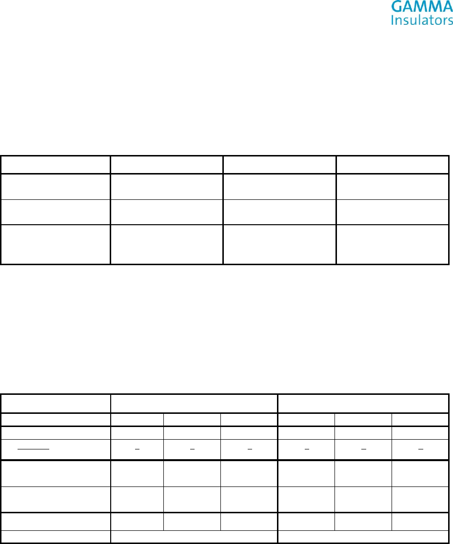
Page 2 of 5
GAMMA Catalog 8435
Design Test Certification
7.2.1 Low-frequency Wet Withstand Voltage
The tests were carried out on three post insulators according to ANSI C29.9, cl. 7.2.1. The rated wet withstand voltage was
applied on each of the tested post insulator for 10 seconds.
The test arrangement was set up according to ANSI C29.1, cl. 3.3
Low-frequency Wet Withstand Voltage Test Results
Sample No. 1
Sample No. 2
Sample No. 3
b (in Hg)
t (°F)
29.42
65.84
29.42
65.84
29.42
65.84
r.i. (mm/min)
RW (Ωm)
5.0
185.0
5.0
185.0
5.0
185.0
VLW (kV) T
(s)
result
100
10
no flashover occurred
100
10
no flashover occurred
100
10
no flashover occurred
No flashover occurred during the test at the rated wet withstand voltage 100 kV specified by ANSI C29.9, Table 2. All test
samples met the requirements. Post type insulator TR-214, Catalog No. 8435 passed low-frequency wet withstand voltage
test according to ANSI C29.9, cl. 7.2.1.
7.2.2 & 7.2.3 Impulse Withstand Voltage Test and Flashover Voltage
The tests were carried out on the three post insulators according to ANSI C29.9, cl. 7.2.2 and 7.2.3. Three consecutive impulses
of the rated impulse-withstand value of both polarities were applied on each of tested post insulator. The critical impulse
voltages of both polarities were determined by the up and down method with 30 impulses.
The test arrangement was set up according to ANSI C29.1, cl. 3.3
Impulse Withstand Voltage and Flashover Voltage Test Results
Polarity
+
-
Test Sample No.
1
2
3
1
2
3
VIW (kV)
250
250
250
250
250
250
Impulses
Flashovers
3
0
3
0
3
0
3
0
3
0
3
0
b (in Hg)
t (°F)
29.48
67.6
29.48
67.6
29.48
67.6
29.48
67.6
29.48
67.6
29.48
67.6
Kh
Kd
1.0029
1.0764
1.0029
1.0764
1.0029
1.0764
1.0029
1.0663
1.0029
1.0663
1.0029
1.0663
VCRS LI (kV)
277
277
276
468
452
482
VCRSA LI (kV)
277
467
No flashover occurred during the test with three impulses at the rated impulse-withstand voltage 250 kV specified by
ANSI C29.9, Table 2. All test samples met the requirements. Post type insulator TR-214, C a t a l og No. 8435 passed
impulse withstand voltage test according to ANSI C29.9, cl. 7.2.3.
The rated critical-impulse flashover voltage 280 kV is specified by ANSI C29.9, Table 2. The average values of critical-impulse
flashover voltages are higher than 92 percent of the rated critical-impulse flashover voltage, i.e. 258 kV. All test samples
met the requirements. Post type insulator TR-214, Catalog No. 843 passed critical-impulse flashover voltage test
according to ANSI C29.9, cl. 7.2.2.
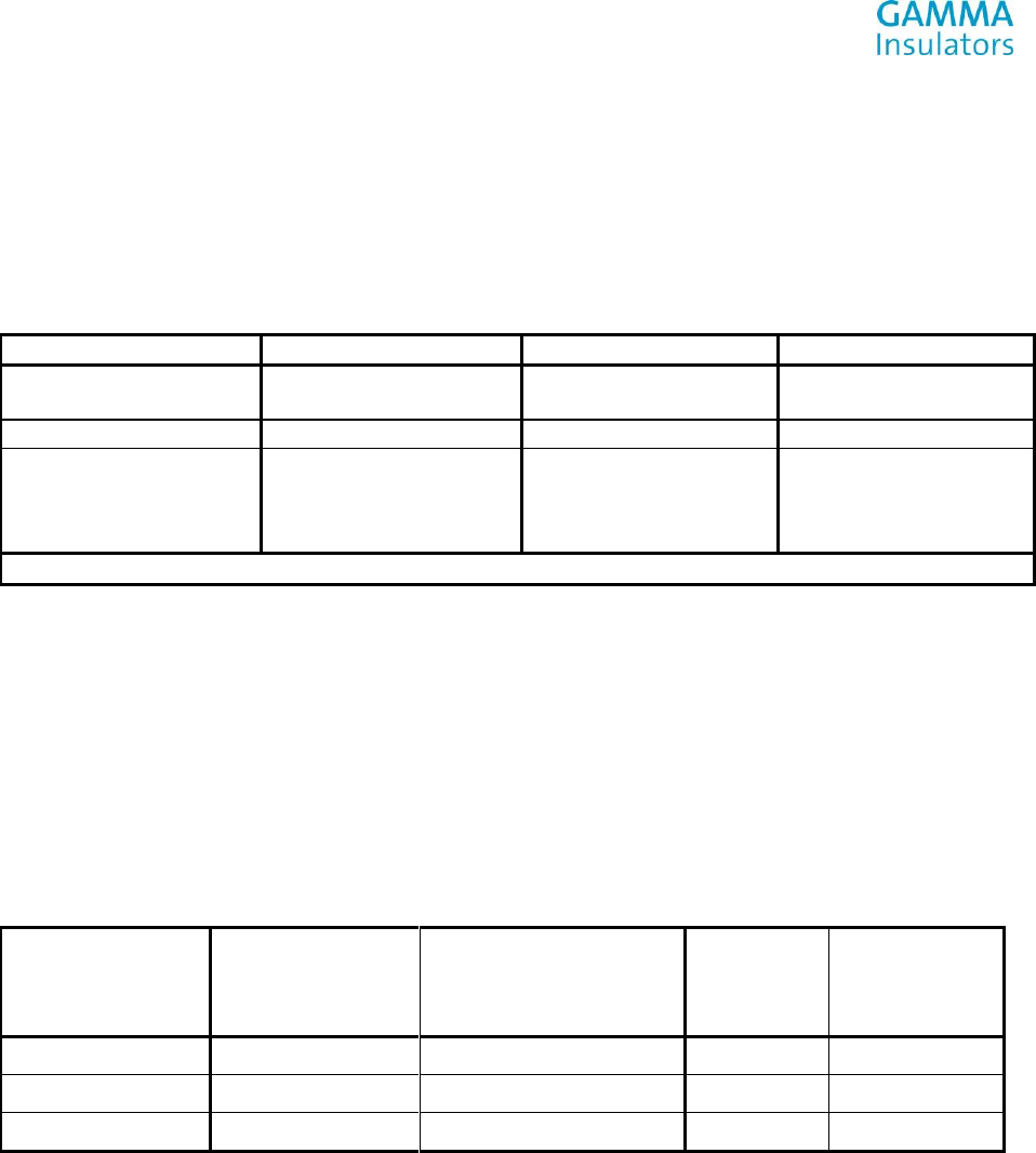
Page 3 of 5
GAMMA Catalog 8435
Design Test Certification
7.2.4 Radio-influence Voltage (RIV) Test
The tests were carried out on three post insulators according to ANSI C29.9, cl. 7.2.4. Radio-influence voltage was measured at
the frequency 1.0 MHz in accordance with circuit diagram in Figure 3 – 3a of NEMA No. 107, Section 3.
The test arrangement was set up according to ANSI C29.1, cl. 4.9.1.
Radio-influence Voltage (RIV) Test Results
Sample No. 1
Sample No. 2
Sample No. 3
b (in Hg)
t (°F)
29,48
63,5
29,48
63,5
29,48
63,5
VT (kV)
RIV (µV)
RIV (µV)
RIV (µV)
33
30
27
0
4
4
4
4
4
4
4
4
4
4
4
4
Rated value: max. 200 µV at 30 kV/1,0 MHz
Measured values of radio-influence voltages on post insulators at test voltage 30 kV (1 MHz) are less than 200 µV specified by
ANSI C29.9, Table 2. All test samples met the requirements. Post type insulator TR-214, Catalog No. 8435 passed radio-
influence voltage test according to ANSI C29.9, cl. 7.2.4.
7.2.5 Thermal Shock Test
The test was carried out on three post insulator according to ANSI C 29.9, cl 7.2.5. Each tested post insulator was first
immersed in a hot water bath 150 °F (66 °C) for 10 minutes. Then it was withdrawn and immersed in a cold water bath
39 °F (4 °C) for 10 minutes. After tenth cycle each post insulator was tested for electrical soundness by low-frequency
momentary flashover voltage test.
Thermal Shock Test Results
10 cycles (150 °F / 10
min and 39 °F/ 10
min)
Low-frequency Momentary
Flashover Voltage Test
Flashover
voltage (kV)
Result
Test Sample No. 1
No failure
No failure
173
Passed
Test Sample No. 2
No failure
No failure
178
Passed
Test Sample No. 3
No failure
No failure
179
Passed
No failure occurred during the thermal shock test according to ANSI C29.9, cl. 7.2.5. All test samples met the requirements.
Post type insulator TR-214, Catalog No. 8435 passed thermal shock test according to ANSI C29.9, cl. 7.2.5.
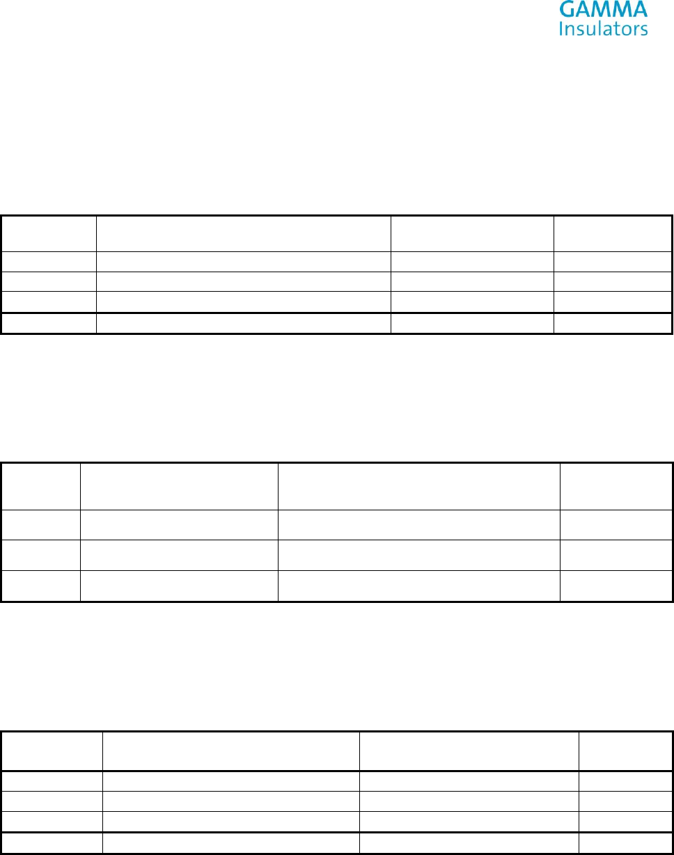
Page 4 of 5
GAMMA Catalog 8435
Design Test Certification
7.2.6 Compression Strength Test
Temperature 68 -71.6 °F (20-22 °C), Minimum failing load 14,994.76 lbs. (66.70 kN). Smooth increase in load 450 - 900 lbs. /s.
(2 - 4 kN/s), smooth load up to failure, visual inspection
Compression Strength Test Results
Sample No.
Maximum failure load
lbs. (kN)
Failure Mode
Result (MFL)
7
(3012)
Sheds
Passed
8
(2035)
Sheds
Passed
9
(3012)
Ceramic core
Passed
Average
(2686)
7.2.7 Torsional Strength Test
Temperature during test + 73.4 °F (+ 23 °C), Minimum failing load (MFL) 11,948.51 lb.-in. (1.35 kNm), Smooth increase in load
265.52- 442.54 lb.-in./s (0.03 – 0.05 kNm/s), Smooth load up to failure of screws
Torsional Strength Test Results
Sample
No.
Maximum reached torsional
moment lbs. (kNm)
Failure Mode
Result (MFL)
10
>75,231.34 (8.5)
Screws failed. Insulator did not fail.
Test stopped by operator.
Passed
11
> 77,001.49 (8.7)
Screws failed. Insulator did not fail.
Test stopped by operator.
Passed
12
> 57,529.85 (6.5)
Insulator did not fail.
Test stopped by operator
Passed
7.3.4 Cantilever Strength Test
Temperature during test + 71.6 °F (+ 22 °C), Minimum failing load (MFL) 2,023.28 lbs. (9 kN), Increase in load
6.74 – 13.49 lbs. /s (0.03 - 0.06 kN/s), smoothly to failure
Cantilever Strength Test Results
Sample
No.
Maximum failing load
lbs. (kN)
Failure Mode
Result (MFL)
1
3,214.77 (14.30)
Failed at bottom part of ceramic core
passed
2
2,203.13 (9.80)
Failed at bottom part of ceramic core
passed
3
3,012.44 (13.4)
Failed at bottom part of ceramic core
passed
Average
2,810.11 (12.5)
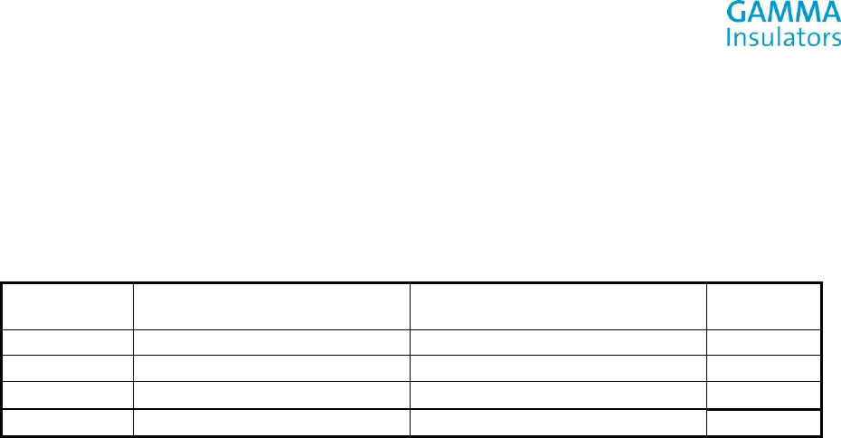
Page 5 of 5
GAMMA Catalog 8435
Design Test Certification
7.3.5 Tensile strength
Temperature 68 – 69.8 °F (20-21 °C), Minimum failing load (MFL) 13,983.11 lbs. (62.2 kN), Increase in load 6.74 – 13.49 lbs./s
(0.3 – 0.6 kN/s), smoothly. Smooth load up to failure, visual inspection
Tensile Strength Test Results
Sample
No.
Maximum failure load
[kN]
Way of failure
Result
(MFL)
4
20,839.79 (92.7)
Ceramic core inside of metal cap
Passed
5
36,081.84 (160.5)
Ceramic core inside of metal cap
Passed
6
28,404.61 (126.35)
Ceramic core inside of metal cap
Passed
Average
28,438.33 (126.5)
Tests performed at EGU HV Laboratory a. s., Test No. 10210/A/15, and The Klockner Institute, Report No.
129/15/AL. All test results contained in this document are held on file under drawing number reference 84351011.
__________________________________
Frank Escobar
Chief Engineer, GAMMA Insulators Corporation

Page 1 of 5
Design Test Certification
Material Tested GAMMA Catalog Number 8436
TEST OBJECT: Station Post Insulator
TYPE SPECIFICATION: TR 216
TEST STANDARDS: ANSI C29.9, ANSI C29.1, NEMA No. 107:1993
SCHEDULE OF TESTS
Design Tests, Section 7.2
Page Test Section Description of Test
Electrical Tests
2 7.2.1 Low-frequency Wet Withstand Voltage
3 7.2.2 & 7.2.3 Critical Impulse Flashover Positive & Impulse Withstand Voltage
5 7.2.4 Radio-influence voltage tests
Mechanical Tests
6 7.2.5 Thermal shock test
7 7.2.6 Compression Strength
8 7.2.7 Torsional Strength
Quality Conformance Tests, Section 7.3
9 7.3.4 Cantilever Strength
10 7.3.5 Tensile Strength
All Electrical tests were performed per the requirements of ANSI test standard C29.9:2012, ANSI C29.1:2012, and
NEMA No. 107:1993. All Mechanical tests were performed per the requirements of ANSI test standard
C29.9 - 1983 (R1996), and ANSI C29.1 – 1988 (R2002).
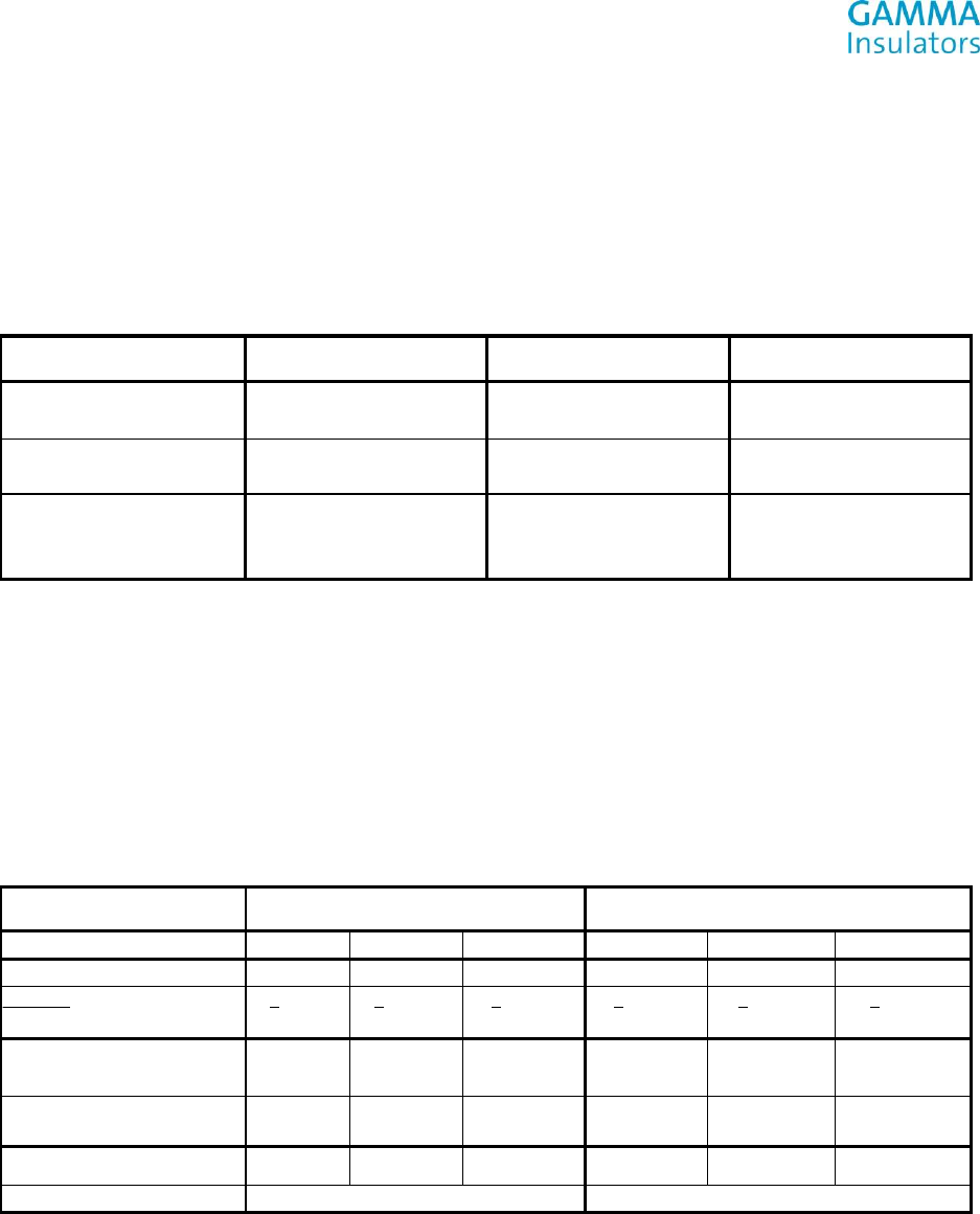
Page 2 of 5
GAMMA Catalog 8436
Design Test Certification
7.2.1 Low-frequency Wet Withstand Voltage
The tests were carried out on three post insulators according to ANSI C29.9, cl. 7.2.1. The rated wet withstand voltage was
applied on each of the tested post insulator for 10 seconds.
The test arrangement was set up according to ANSI C29.1, cl. 3.3
Low-frequency Wet Withstand Voltage Test Results
Sample No. 1
Sample No. 2
Sample No. 3
b (in Hg)
t (°F)
29.42
67.1
29.42
67.1
29.42
67.1
r.i. (mm/min)
RW (Ωm)
5.0
185.0
5.0
185.0
5.0
185.0
VLW (kV)
T (s)
Result
145
10
no flashover occurred
145
10
no flashover occurred
145
10
no flashover occurred
No flashover occurred during the test at the rated wet withstand voltage 145 kV specified by ANSI C29.9, Table 2. All test
samples met the requirements. Post type insulator TR-216, Catalog No. 8436 passed low-frequency wet withstand voltage
test according to ANSI C29.9, cl. 7.2.1.
7.2.2 & 7.2.3 Impulse Withstand Voltage Test and Flashover Voltage
The tests were carried out on the three post insulators according to ANSI C29.9, cl. 7.2.2 and 7.2.3. Three consecutive impulses
of the rated impulse-withstand value of both polarities were applied on each of tested post insulator. The critical impulse
voltages of both polarities were determined by the up and down method with 30 impulses.
The test arrangement was set up according to ANSI C29.1, cl. 3.3
Impulse Withstand Voltage and Flashover Voltage Test Results
Polarity
+
-
Test Sample No.
1
2
3
1
2
3
VIW (kV)
350
350
350
350
350
350
Impulses
Flashovers
3
0
3
0
3
0
3
0
3
0
3
0
b (in Hg)
t (°F)
29.48
64.6
29.48
64.6
29.48
64.6
29.48
64.6
29.48
64.6
29.48
64.6
Kh
Kd
1.0088
1.0823
1.0088
1.0823
1.0088
1.0823
1.0088
1.0714
1.0088
1.0714
1.0088
1.0714
VCRS LI (kV)
383
386
381
630
640
617
VCRSA LI (kV)
383
629
No flashover occurred during the test with three impulses at the rated impulse-withstand voltage
350 kV specified by ANSI C29.9, Table 2, All test samples met the requirements. Post type insulator TR-216, Catalog No. 8436
passed impulse withstand voltage test according to ANSI C29.9, cl. 7.2.3.
The rated critical-impulse flashover voltage 390 kV is specified by ANSI C29.9, Table 2. The average values of critical-impulse
flashover voltages are higher than 92 percent of the rated critical-impulse flashover voltage, i.e. 359 kV. All test samples
met the requirements. Post type insulator TR-216, Catalog No. 8436 passed critical-impulse flashover voltage test according
to ANSI C29.9, cl. 7.2.2.
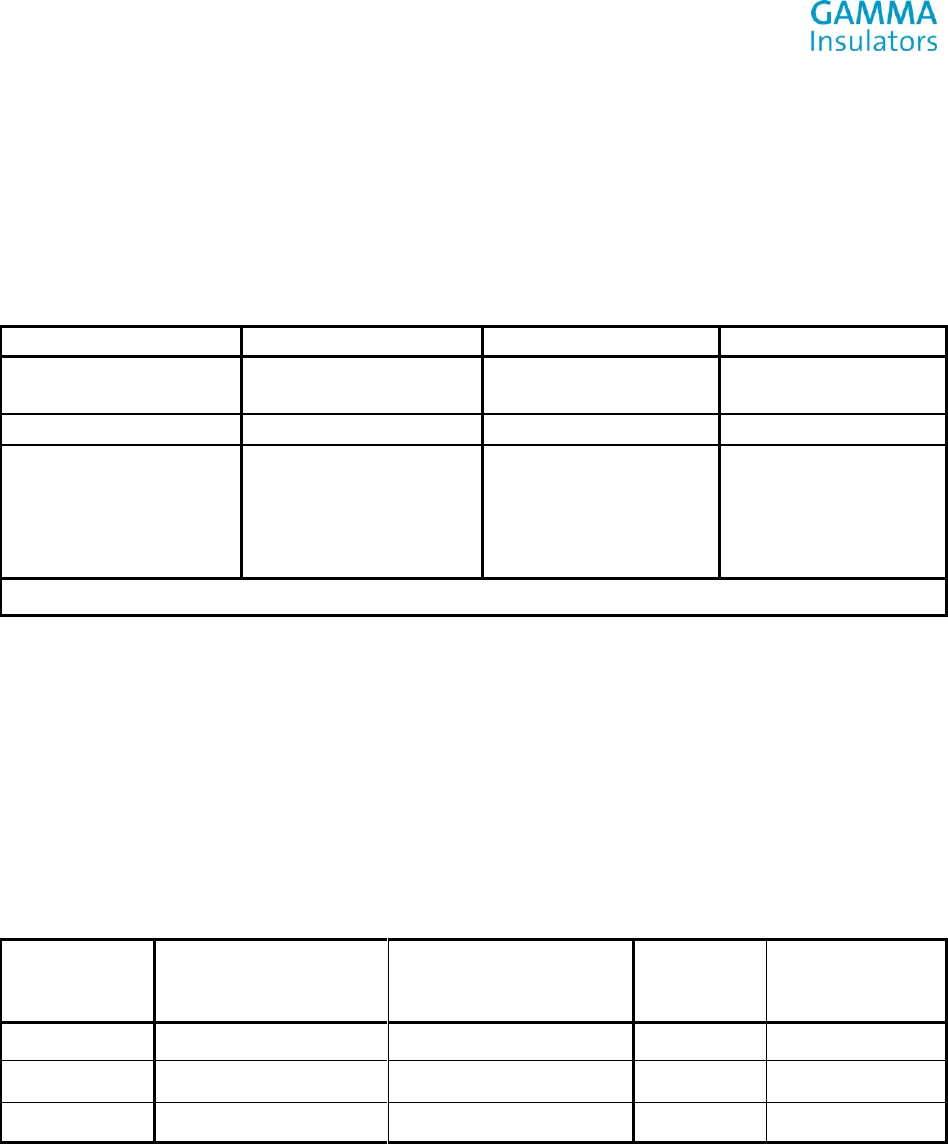
Page 3 of 5
GAMMA Catalog 8436
Design Test Certification
7.2.4 Radio-influence Voltage (RIV) Test
The tests were carried out on three post insulators according to ANSI C29.9, cl. 7.2.4. Radio-influence voltage was measured at
the frequency 1.0 MHz in accordance with circuit diagram in Figure 3 – 3a of NEMA No. 107, Section 3.
The test arrangement was set up according to ANSI C29.1, cl. 4.9.1.
Radio-influence Voltage (RIV) Test Results
Sample No. 1
Sample No. 2
Sample No. 3
b (in Hg)
t (°F)
29.48
63.5
29.48
63.5
29.48
63.5
VT (kV)
RIV (µV)
RIV (µV)
RIV (µV)
48
44
40
36
0
4
4
4
4
4
4
4
4
4
4
4
4
4
4
4
Rated value: max. 200 µV at 30 kV/1,0 MHz
Measured values of radio-influence voltages on post insulators at test voltage 44 kV (1 MHz) are less than 200 µV specified by
ANSI C29.9, Table 2. All test samples met the requirements. Post type insulator TR-216, Catalog No. 8436 passed radio-
influence voltage test according to ANSI C29.9, cl. 7.2.4.
7.2.5 Thermal Shock Test
The test was carried out on three post insulator according to ANSI C 29.9, cl 7.2.5. Each tested post insulator was first
immersed in a hot water bath 150 °F (66 °C) for 10 minutes. Then it was withdrawn and immersed in a cold water bath 39 F (4
°C) for 10 minutes. After tenth cycle each post insulator was tested for electrical soundness by low-frequency momentary
flashover voltage test.
Thermal Shock Test Results
10 cycles (150 °F / 10 min and
39 °F/ 10 min)
Low-frequency Momentary
Flashover Voltage Test
Flashover
voltage (kV)
Result
Test Sample No. 1
No failure
No failure
242
Passed
Test Sample No. 2
No failure
No failure
246
Passed
Test Sample No. 3
No failure
No failure
241
Passed
No failure occurred during the thermal shock test according to ANSI C29.9, cl. 7.2.5. All test samples met the requirements.
Post type insulator TR-216, Catalog No. 8436 passed thermal shock test according to ANSI C29.9, cl. 7.2.5.
Page 4 of 5
GAMMA Catalog 8436
Design Test Certification
7.2.6 Compression Strength Test
Temperature 68 -71.6 °F (20-22 °C), Minimum failing load 24,998.75 lbs. (111.2 kN). Smooth increase in load
450 - 900 lbs./s. (2 - 4 kN/s), Smooth load up to failure, visual inspection
Compression Strength Test Results
Sample No.
Maximum failure load lbs. (kN)
Failure Mode
Result (MFL)
7
(3754)
Ceramic core
Passed
8
(3628)
Ceramic core
Passed
9
(3472)
Ceramic core
Passed
Average
(3618)
7.2.7 Torsional Strength Test
Temperature during test + 73.4 °F (+ 23 °C), Minimum failing load (MFL) 15,002 lb.-in. (1.695 kNm), Smooth increase in load
265.52- 442.54 lb.-in./s (0.03 – 0.05 kNm/s), Smooth load up until 57,530 lb.-in. (6.5 kNm) – The limit of screws used, test
stopped by operator, visual inspection.
Torsional Strength Test Results
Sample
No.
Maximum Reached Torsional Moment
lbs.-in. (kNm)
Failure Mode
Result (MFL)
10
>57,530 (6.5)
Insulator did not fail.
Test stopped by operator.
Passed
11
>57,530 (6.5)
Insulator did not fail.
Test stopped by operator
Passed
12
>57,530 (6.5)
Insulator did not fail.
Test stopped by operator
Passed
7.3.4 Cantilever Strength Test
Temperature during test + 71.6 °F (+ 22 °C), Minimum failing load (MFL) 1,506.22 lbs. (6. kN), Increase in load 6.74 – 13.49 lbs.
/s (0.03 - 0.06 kN/s), smoothly until failure
Cantilever Strength Test Results
Sample
No.
Maximum failing load lbs. (kN]
Failure Mode
Result (MFL)
1
2,855.07 (12.7)
Failed at bottom part of ceramic core
Passed
2
1775.99 (7.9)
Failed at bottom part of ceramic core
Passed
3
2472.90 (11.0)
Failed at bottom part of ceramic core
Passed
Average
2360.50 (10.5)
Page 5 of 5
GAMMA Catalog 8436
Design Test Certification
7.3.5 Tensile strength
Temperature 68 – 69.8 °F (20-21 °C), Minimum failing load (MFL) 16,006.40 lbs. (71.2 kN), Increase in load 6.74 – 13.49 lbs./s
(0.3 – 0.6 kN/s), smoothly. Smooth load up to Failure, visual inspection.
Tensile Strength Test Results
Sample
No.
Maximum failure load
lbs. (kN)
Failure Mode
Result (MFL)
4
25,628.22 (114.0)
Ceramic core inside of metal cap
Passed
5
23,649.90 (105.2)
Ceramic core inside of metal cap
Passed
6
24,661.54 (109.7)
Ceramic core inside of metal cap
Passed
Average
24,639.06 (109.6)
Tests performed at EGU HV Laboratory a. s., Test No.10201/B/15, and The Klokner Institute, Report No. 128/15/AL.
All test results contained in this document are held on file under drawing number reference 84361011.
__________________________________
Frank Escobar
Chief Engineer, GAMMA Insulators Corporation

Page 1 of 5
Design Test Certification
Material Tested GAMMA-CERISOL Catalog Number 288SU0650
TEST OBJECT: Station Post Insulator
TYPE SPECIFICATION: TR 288
TEST STANDARDS: ANSI C29.9, ANSI C29.1, NEMA No. 107:1993
SCHEDULE OF TESTS
Design Tests, Section 7.2
Page Test Section Description of Test
Electrical Tests
2 7.2.1 Low-frequency Wet Withstand Voltage
3 7.2.2 & 7.2.3 Critical Impulse Flashover Positive & Impulse Withstand Voltage
5 7.2.4 Radio-influence voltage tests
Mechanical Tests
6 7.2.5 Thermal shock test
7 7.2.6 Compression Strength
8 7.2.7 Torsional Strength
Quality Conformance Tests, Section 7.3
9 7.3.4 Cantilever Strength
10 7.3.5 Tensile Strength
All Electrical tests were performed per the requirements of ANSI test standard C29.9:2012, ANSI C29.1:2012, and
NEMA No. 107:1993. All Mechanical tests were performed per the requirements of ANSI test standard
C29.9 - 1983 (R1996), and ANSI C29.1 – 1988 (R2002).
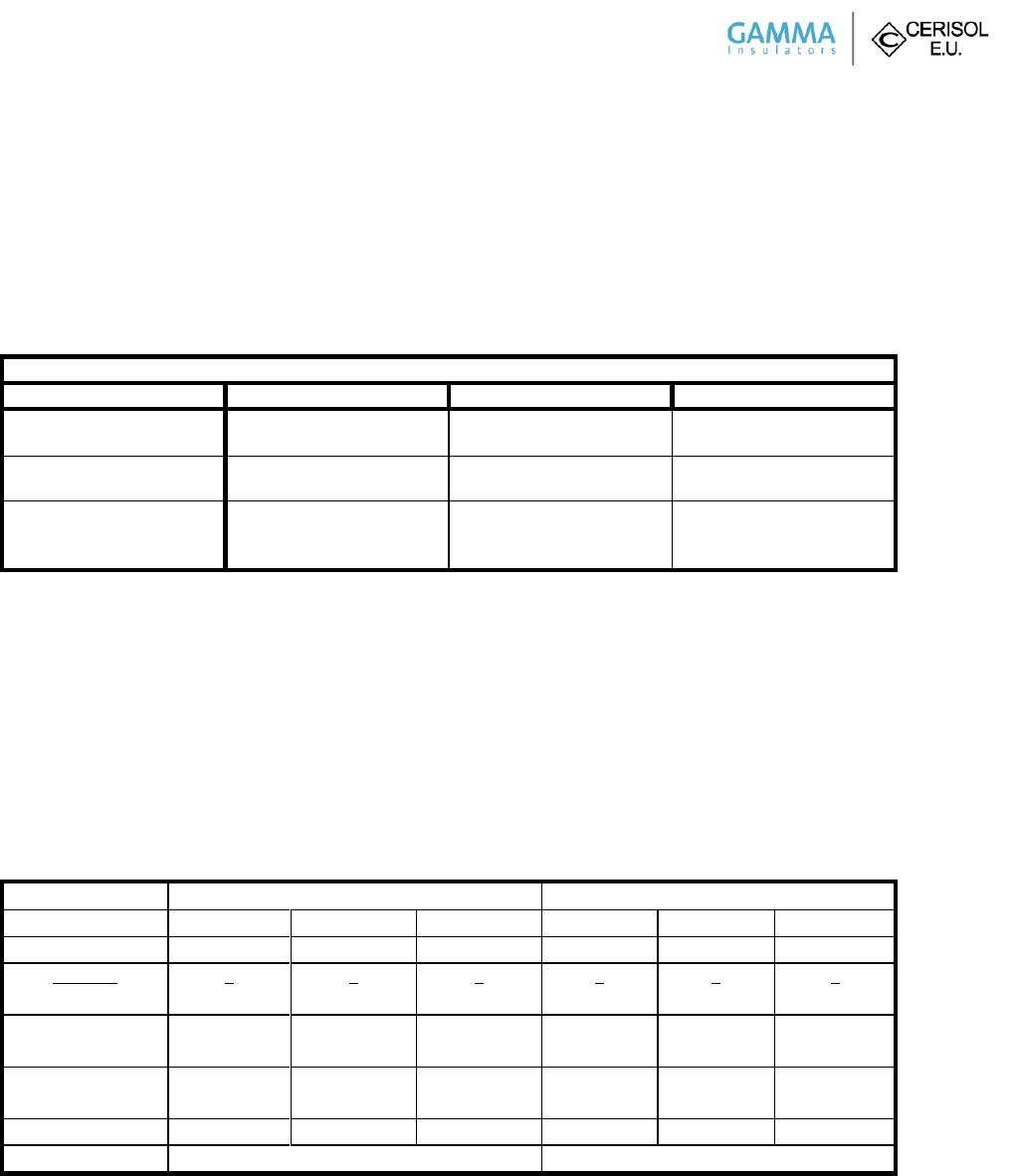
Page 2 of 5
GAMMA-CERISOL Catalog 288SU0650
Design Test Certification
7.2.1 Low-frequency Wet Withstand Voltage
The tests were carried out on three post insulators according to ANSI C29.9, cl. 7.2.1. The rated wet withstand voltage was
applied on each of the tested post insulator for 10 seconds.
The test arrangement was set up according to ANSI C29.1, cl. 3.3
Low-frequency Wet Withstand Voltage Test Results
Station post insulator
Sample No. 1
Sample No.2
Sample No.3
b (in Hg)
t (°F)
28.88
60.6
28.88
60.6
28.88
60.6
r.i. (mm/min)
Rw (Ωm)
5.0
200.0
5.0
200.0
5.0
200.0
VLW (kV)
T (s)
result
275
10
No flashover occurred
275
10
No flashover occurred
275
10
No flashover occurred
No flashover occurred during the test at the rated wet withstand voltage 275 kV specified by ANSI C29.9, Table 2. All test
samples met the requirements. Station post insulator TR 288, Catalog No. 288SU0650 passed low-frequency wet withstand
voltage tests according to ANSI C29.9, cl. 7.2.1.
7.2.2 & 7.2.3 Impulse Withstand Voltage Test and Flashover Voltage
The tests were carried out on the three post insulators according to ANSI C29.9, cl. 7.2.2 and 7.2.3. Three consecutive impulses
of the rated impulse-withstand value of both polarities were applied on each of tested post insulator. The critical impulse
voltages of both polarities were determined by the up and down method with 30 impulses.
The test arrangement was set up according to ANSI C29.1, cl. 3.3
Impulse Withstand Voltage and Flashover Voltage Test Results
Polarity
+
-
Test sample No.
1
2
3
1
2
3
VIW (kV)
650
650
650
650
650
650
Impulses
Flashovers
3
0
3
0
3
0
3
0
3
0
3
0
b (in Hg)
t (°F)
28.85
60.6
28.85
60.6
28.76
61.7
28.85
60.6
28.85
60.6
28.76
61.7
Kh
Kd
1.066
0.995
1.066
0.995
1.061
0.990
1.058
0.995
1.058
0.995
1.054
0.990
VCRS LI (kV)
701
711
706
863
846
829
VCRSA LI (kV)
706
846
No flashover occurred during the test with three impulses at the rated impulse-withstand voltage 650 kV specified by ANSI
C29.9, Table 2. All test samples met the requirements. Station post insulator TR 288, Catalog No. 288SU0650 passed impulse
withstand voltage tests according to ANSI C29.9, cl. 7.2.3.
The rated critical-impulse flashover voltage 710 kV is specified by ANSI C29.9, Table 2. The average values of critical-impulse
flashover voltages are higher than 92 percent of the rated critical-impulse flashover voltage, i.e. 653 kV. All test samples met
Page 3 of 5
the requirements. Station post insulator TR 288, Catalog No. 288SU0650 passed critical impulse flashover voltage tests
according to ANSI C29.9, cl. 7.2.2.
GAMMA-CERISOL Catalog 288SU0650
Design Test Certification
7.2.4 Radio-influence Voltage (RIV) Test
The tests were carried out on three post insulators according to ANSI C29.9, cl. 7.2.4. Radio-influence voltage was measured at
the frequency 1.0 MHz in accordance with circuit diagram in Figure 3 – 3a of NEMA No. 107, Section 3.
The test arrangement was set up according to ANSI C29.1, cl. 4.9.1.
Radio-influence Voltage (RIV) Test Results
Station post insulator
Sample No.1
Sample No.2
Sample No. 3
b (in Hg)
t (°F)
29.03
59.5
29.03
59.7
29.03
59.7
VT (kV)
RIV (µV)
RIV (µV)
RIV (µV)
97
88
79
70
61
0
6
6
6
6
6
6
6
6
6
6
6
6
6
6
6
6
6
6
Rated value: ma. 200 µV at 88 kV/1.0 MHz
Measured values of radio-influence voltages on post insulators at test voltage 88kV (1MHz) are less than 200 µV specified by
ANSI C29.9, Table 2. All test samples met the requirements. Station post insulator TR 288, Catalog No. 288SU0650 passed
radio-influence voltage tests according to ANSI C29.9, cl. 7.2.4.
7.2.5 Thermal Shock Test
The test was carried out on three post insulator according to ANSI C 29.9, cl 7.2.5. Each tested post insulator was first
immersed in a hot water bath 150 °F (66 °C) for 10 minutes. Then it was withdrawn and immersed in a cold water bath
39 °F (4 °C) for 10 minutes. After tenth cycle each post insulator was tested for electrical soundness by low-frequency
momentary flashover voltage test.
Thermal Shock Test Results
10 cycles
(150 °F/ 10 min and 39 °F/ 10
min)
Low-frequency Momentary
Flashover Voltage Test
Flashover voltage
(kV)
Result
Test sample #1
No failure
No failure
410
Passed
Test sample #2
No failure
No failure
404
Passed
Test sample #3
No failure
No failure
413
Passed
No Failure occurred during the thermal shock test according to ANSI C29.9, cl. 7.2.5. All test samples met the requirements.
Station post insulator TR 288, Catalog No. 288SU0650 passed thermal shock test according to ANSI C29.9, cl. 7.2.5.
Page 4 of 5
GAMMA-CERISOL Catalog 288SU0650
Design Test Certification
7.2.6 Compression Strength Test
Temperature 68 -71.6 °F (20-22 °C), Minimum failing load 60,000 lbs. (266.880 kN). Smooth increase in load 450 - 900 lbs. /s.
(2 - 4 kN/s), Smooth load up until 67,442.68 lbs. (300 kN), 3 sec hold on this level and unloading, visual inspection.
Compression Strength Test Results
Sample No.
Load 67,442.68 lbs. (300 kN)
Applied for 3 sec
Result (MFL)
1
Insulator did not fail
Passed
2
Insulator did not fail
Passed
3
Insulator did not fail
Passed
7.2.7 Torsional Strength Test
Temperature during test + 73.4 °F (+ 23 °C), Minimum failing load (MFL) 40,000 lb.-in. (4.52 kNm), Smooth increase in load
265.52- 442.54 lb.-in./s (0.03 – 0.05 kNm/s), Smooth load up until 44,253.73 lb.-in. (5 kNm), 3 sec hold on this level and
unloading, visual inspection.
Torsional Strength Test Results
Sample No.
Torsional moment 44,253.73 lb.-in. (5 kNm)
Applied for 3 sec
Result (MFL)
1
Insulator did not fail
Passed
2
Insulator did not fail
Passed
3
Insulator did not fail
Passed
7.3.4 Cantilever Strength Test
Temperature during test + 71.6 °F (+ 22 °C), Minimum failing load (MFL) 1,400 lbs. (6.227 kN), Increase in load
6.74 – 13.49 lbs. /s (0.03 - 0.06 kN/s), smoothly until failure
Cantilever Strength Test Results
Sample No.
Maximum failing load lbs. (kN)
Way of failure
Result
(MFL)
1
2,592.05 lbs. (11.53kN)
Failed at bottom part of ceramic core
Passed
2
2,189.64 lbs. ( 9.74kN)
Failed at bottom part of ceramic core
Passed
3
2,297.55 lbs. (10.22kN)
Failed at bottom part of ceramic core
Passed
Average
2,358.25 lbs. (10.49kN)
Page 5 of 5
GAMMA-CERISOL Catalog 288SU0650
Design Test Certification
7.3.5 Tensile strength
Temperature 68 – 69.8 °F (20-21 °C), Minimum failing load (MFL) 20,000 lbs. (88.96 kN), Increase in load 6.74 – 13.49 lbs./s
(0.3 – 0.6 kN/s), smoothly. Smooth load up until 21,356.85.07 lbs. (95 kN), 3 sec hold on this level and unloading, visual
inspection.
Tensile Strength Test Results
Sample No.
Load 21,356.07 lbs. (95 kN)
Applied for 3 sec
Result (MFL)
1
Insulator did not fail
Passed
2
Insulator did not fail
Passed
3
Insulator did not fail
Passed
Tests performed at EGU HV Laboratory a. s., Test No.10060/B/14, and The Klokner Institute, Report No. 57/14/AL.
All test results contained in this document are held on file under drawing number reference H21288EJ.
__________________________________
Frank Escobar
Chief Engineer, GAMMA Insulators Corporation

Design Test Certification
Material Tested GAMMA-CERISOL Catalog Number 308HU0900
TEST OBJECT: Station Post Insulator
TYPE SPECIFICATION: TR 308
TEST STANDARDS: ANSI C29.9, ANSI C29.1, NEMA No. 107:1993
SCHEDULE OF TESTS
Design Tests, Section 7.2
Page Test Section Description of Test
Electrical Tests
2 7.2.1 Low-frequency Wet Withstand Voltage
3 7.2.2 & 7.2.3 Critical Impulse Flashover Positive & Impulse Withstand Voltage
5 7.2.4 Radio-influence voltage tests
Mechanical Tests
6 7.2.5 Thermal shock test
7 7.2.6 Compression Strength
8 7.2.7 Torsional Strength
Quality Conformance Tests, Section 7.3
9 7.3.4 Cantilever Strength
10 7.3.5 Tensile Strength
All Electrical tests were performed per the requirements of ANSI test standard C29.9:2012, ANSI C29.1:2012, and
NEMA No. 107:1993. All Mechanical tests were performed per the requirements of ANSI test standard
C29.9 - 1983 (R1996), and ANSI C29.1 – 1988 (R2002).
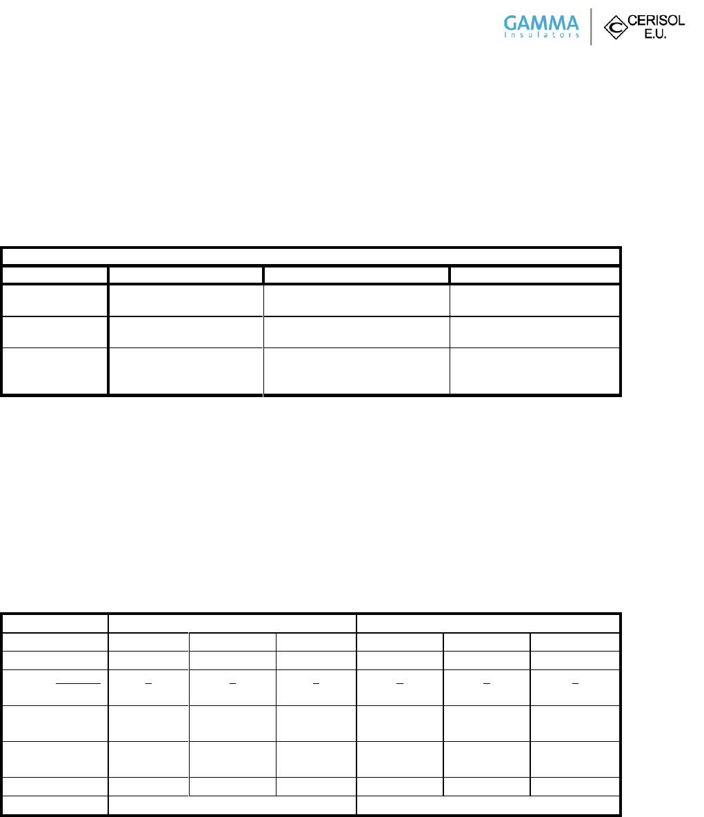
Page 2 of 5
GAMMA-CERISOL Catalog 308HU0900
Design Test Certification
7.2.1 Low-frequency Wet Withstand Voltage
The tests were carried out on three post insulators according to ANSI C29.9, cl. 7.2.1. The rated wet withstand voltage was
applied on each of the tested post insulator for 10 seconds.
The test arrangement was set up according to ANSI C29.1, cl. 3.3
Low-frequency Wet Withstand Voltage Test Results
Station post insulator
Sample No. 1
Sample No.2
Sample No.3
b (in Hg)
t (°F)
28.79
60.6
28.79
60.6
28.79
60.6
r.i. (mm/min)
Rw (Ωm)
5.0
200.0
5.0
200.0
5.0
200.0
VLW (kV)
T (s)
result
385
10
No flashover occurred
385
10
No flashover occurred
385
10
No flashover occurred
No flashover occurred during the test at the rated wet withstand voltage 385 kV specified by ANSI C29.9, Table 2. All test
samples met the requirements. Station post insulator TR 308, Catalog No. 308HU0900 passed low-frequency wet withstand
voltage tests according to ANSI C29.9, cl. 7.2.1.
7.2.2 & 7.2.3 Impulse Withstand Voltage Test and Flashover Voltage
The tests were carried out on the three post insulators according to ANSI C29.9, cl. 7.2.2 and 7.2.3. Three consecutive impulses
of the rated impulse-withstand value of both polarities were applied on each of tested post insulator. The critical impulse
voltages of both polarities were determined by the up and down method with 30 impulses.
The test arrangement was set up according to ANSI C29.1, cl. 3.3
Impulse Withstand Voltage and Flashover Voltage Test Results
Polarity
+
-
Test Sample No.
1
2
3
1
2
3
VIW (kV)
1010
1010
1010
1010
1010
1010
Impulses
Flashovers
3
0
3
0
3
0
3
0
3
0
3
0
b (in Hg)
t (°F)
28.79
61.0
28.79
61.0
28.79
61.0
28.79
61.0
28.79
61.0
28.79
61.0
Kh
Kd
1.064
0.992
1.064
0.992
1.064
0.992
1.056
0.992
1.056
0.992
1.056
0.992
VCRS LI (kV)
1112
1105
1106
1277
1277
1299
VCRSA LI (kV)
1108
1284
No flashover occurred during the test with three impulses at the rated impulse-withstand voltage 1010 kV specified by ANSI
C29.9, Table 2. All test samples met the requirements. Station post insulator TR 308, Catalog No. 308HU0900 passed impulse
withstand voltage tests according to ANSI C29.9, cl. 7.2.3.
The rated critical-impulse flashover voltage 1010 kV is specified by ANSI C29.9, Table 2. The average values of critical-impulse
flashover voltages are higher than 92 percent of the rated critical-impulse flashover voltage, i.e. 929 kV. All test samples met

Page 3 of 5
the requirements. Station post insulator TR 308, Catalog No. 308HU0900 passed critical impulse flashover voltage tests
according to ANSI C29.9, cl. 7.2.2.
GAMMA-CERISOL Catalog 308HU0900
Design Test Certification
7.2.4 Radio-influence Voltage (RIV) Test
The tests were carried out on three post insulators according to ANSI C29.9, cl. 7.2.4. Radio-influence voltage was measured at
the frequency 1.0 MHz in accordance with circuit diagram in Figure 3 – 3a of NEMA No. 107, Section 3.
The test arrangement was set up according to ANSI C29.1, cl. 4.9.1.
Radio-influence Voltage (RIV) Test Results
Station post insulator
Sample No.1
Sample No.2
Sample No. 3
b (in Hg)
t (°F)
29.00
60.3
29.00
60.3
29.00
60.4
VT (kV)
RIV (µV)
RIV (µV)
RIV (µV)
161
146
131
116
101
86
71
0
141
45
10
6
6
6
6
6
63
32
20
11
7
6
6
6
100
50
14
9
6
6
6
6
Rated value: ma. 500 µV at 146 kV/1.0 MHz
Measured values of radio-influence voltages on post insulators at test voltage 146kV (1MHz) are less than 500 µV specified by
ANSI C29.9, Table 2. All test samples met the requirements. Station post insulator TR 308, Catalog No. 308HU0900 passed
radio-influence voltage tests according to ANSI C29.9, cl. 7.2.4.
7.2.5 Thermal Shock Test
The test was carried out on three post insulator according to ANSI C 29.9, cl 7.2.5. Each tested post insulator was first
immersed in a hot water bath 150 °F (66 °C) for 10 minutes. Then it was withdrawn and immersed in a cold water bath
39 °F (4 °C) for 10 minutes. After tenth cycle each post insulator was tested for electrical soundness by low-frequency
momentary flashover voltage test.
Thermal Shock Test Results
10 cycles
(150 °F/ 10 min, and 39 °F/ 10 min)
Low-frequency Momentary
Flashover Voltage Test
Flashover
voltage (kV)
Result
Test sample #1
No failure
No failure
596
Passed
Test sample #2
No failure
No failure
585
Passed
Test sample #3
No failure
No failure
591
Passed
No Failure occurred during the thermal shock test according to ANSI C29.9, cl. 7.2.5. All test samples met the requirements.
Station post insulator TR 308, Catalog No. 308HU0900 passed thermal shock test according to ANSI C29.9, cl. 7.2.5.
Page 4 of 5
GAMMA-CERISOL Catalog 308HU0900
Design Test Certification
7.2.6 Compression Strength Test
Temperature 68 -71.6 °F (20-22 °C), Minimum failing load 75,000 lbs. (333.6 kN). Smooth increase in load 450 - 900 lbs. /s.
(2 - 4 kN/s), Smooth load up until 89,923 lbs. (400 kN), 3 sec hold on this level and unloading, visual inspection.
Compression Strength Test Results
Sample No.
Load 89,923 lbs. (400kN)
Applied for 3 sec
Result (MFL)
1
Insulator did not fail
Passed
2
Insulator did not fail
Passed
3
Insulator did not fail
Passed
7.2.7 Torsional Strength Test
Temperature during test + 73.4 °F (+ 23 °C), Minimum failing load (MFL) 90,000 lb.-in. (10.17 kNm), Smooth increase in load
265.52- 442.54 lb.-in./s (0.03 – 0.05 kNm/s), Smooth load up until 92,932.83 lb.-in. (10.5 kNm), 3 sec hold on this level and
unloading, visual inspection.
Torsional Strength Test Results
Sample No.
Torsional moment 92,932.83 lb.-in. (10.5 kNm)
Applied for 3 sec
Result (MFL)
1
Insulator did not fail
Passed
2
Insulator did not fail
Passed
3
Insulator did not fail
Passed
7.3.4 Cantilever Strength Test
Temperature during test + 71.6 °F (+ 22 °C), Minimum failing load (MFL) 1,450 lbs. (6.45 kN), Increase in load 6.74 – 13.49 lbs. /s
(0.03 - 0.06 kN/s), smoothly until failure
Cantilever Strength Test Results
Sample No.
Maximum failing load, lbs. (kN)
Way of failure
Result (MFL)
1
1,978.32 (8.8)
Failed at bottom part of ceramic core
Passed
2
2,176.15 (9.68)
Failed at bottom part of ceramic core
Passed
3
2,000.80 (8.9)
Failed at bottom part of ceramic core
Passed
Average
2,050.26 (9.12)
Page 5 of 5
GAMMA-CERISOL Catalog 308HU0900
Design Test Certification
7.3.5 Tensile strength
Temperature 68 – 69.8 °F (20-21 °C), Minimum failing load (MFL) 25,000 lbs. (111.2 kN), Increase in load 6.74 – 13.49 lbs./s
(0.3 – 0.6 kN/s), smoothly. Smooth load up until 26,977.07 lbs. (120 kN), 3 sec hold on this level and unloading, visual
inspection.
Tensile Strength Test Results
Sample No.
Load 26,977.07 lbs. (120 kN)
Applied for 3 sec
Result (MFL)
1
Insulator did not fail
Passed
2
Insulator did not fail
Passed
3
Insulator did not fail
Passed
Tests performed at EGU HV Laboratory a. s., Test No.10060/C/14, and The Klokner Institute, Report No. 56/14/AL.
All test results contained in this document are held on file under drawing number reference H21308EJ.
__________________________________
Frank Escobar
Chief Engineer, GAMMA Insulators Corporation

Page 1 of 5
Design Test Certification
Material Tested GAMMA-CERISOL Catalog Number 369ET1300
TEST OBJECT: Station Post Insulator
TYPE SPECIFICATION: TR 369
TEST STANDARDS: ANSI C29.9, ANSI C29.1, NEMA No. 107:1993
SCHEDULE OF TESTS
Design Tests, Section 7.2
Page Test Section Description of Test
Electrical Tests
2 7.2.1 Low-frequency Wet Withstand Voltage
3 7.2.2 & 7.2.3 Critical Impulse Flashover Positive & Impulse Withstand Voltage
5 7.2.4 Radio-influence voltage tests
Mechanical Tests
6 7.2.5 Thermal shock test
7 7.2.6 Compression Strength
8 7.2.7 Torsional Strength
Quality Conformance Tests, Section 7.3
9 7.3.4 Cantilever Strength
10 7.3.5 Tensile Strength
All Electrical tests were performed per the requirements of ANSI test standard C29.9:2012, ANSI C29.1:2012, and
NEMA No. 107:1993. All Mechanical tests were performed per the requirements of ANSI test standard
C29.9 - 1983 (R1996), and ANSI C29.1 – 1988 (R2002).
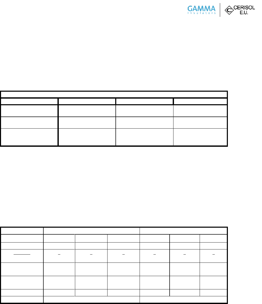
Page 2 of 5
GAMMA-CERISOL Catalog 369ET1300
Design Test Certification
7.2.1 Low-frequency Wet Withstand Voltage
The tests were carried out on three post insulators according to ANSI C29.9, cl. 7.2.1. The rated wet withstand voltage was
applied on each of the tested post insulator for 10 seconds.
The test arrangement was set up according to ANSI C29.1, cl. 3.3
Low-frequency Wet Withstand Voltage Test Results
Station post insulator
Sample No. 1
Sample No.2
Sample No.3
b (in Hg)
t (°F)
28.82
59.4
28.82
59.4
28.82
59.4
r.i. (mm/min)
Rw (Ωm)
4.9
200.0
4.9
200.0
4.9
200.0
VLW (kV)
T (s)
result
525
10
No flashover occurred
525
10
No flashover occurred
525
10
No flashover occurred
No flashover occurred during the test at the rated wet withstand voltage 525 kV specified by ANSI C29.9, Table 2. All test
samples met the requirements. Station post insulator TR 369, Catalog No. 369ET1300 passed low-frequency wet withstand
voltage tests according to ANSI C29.9, cl. 7.2.1.
7.2.2 & 7.2.3 Impulse Withstand Voltage Test and Flashover Voltage
The tests were carried out on the three post insulators according to ANSI C29.9, cl. 7.2.2 and 7.2.3. Three consecutive impulses
of the rated impulse-withstand value of both polarities were applied on each of tested post insulator. The critical impulse
voltages of both polarities were determined by the up and down method with 30 impulses.
The test arrangement was set up according to ANSI C29.1, cl. 3.3
Impulse Withstand Voltage and Flashover Voltage Test Results
Polarity
+
-
Test sample no.
1
2
3
1
2
3
VIW (kV)
1410
1410
1410
1410
1410
1410
Impulses
Flashovers
3
0
3
0
3
0
3
0
3
0
3
0
b (in Hg)
t (°F)
28.82
60.6
28.88
60.4
28.82
60.6
28.82
60.6
28.88
60.4
28.82
60.6
Kh
Kd
1.073
0.994
1.066
0.996
1.073
0.994
1.064
0.994
1.058
0.996
1.064
0.994
VCRS LI (kV)
1470
1438
1446
1650
1645
1639
VCRSA LI (kV)
1451
1645
No flashover occurred during the test with three impulses at the rated impulse-withstand voltage 1410 kV specified by ANSI
C29.9, Table 2. All test samples met the requirements. Station post insulator TR 369, Catalog No. 369ET1300 passed impulse
withstand voltage tests according to ANSI C29.9, cl. 7.2.3.
The rated critical-impulse flashover voltage 1410 kV is specified by ANSI C29.9, Table 2. The average values of critical-impulse
flashover voltages are higher than 92 percent of the rated critical-impulse flashover voltage, i.e. 1297 kV. All test samples met
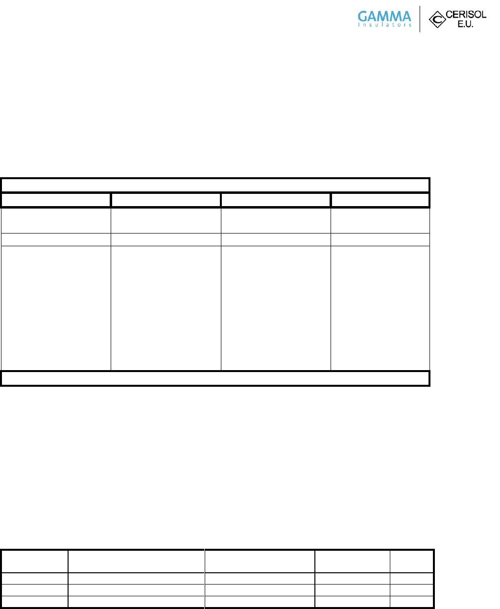
Page 3 of 5
the requirements. Station post insulator TR 369, Catalog No. 369ET1300 passed critical impulse flashover voltage tests
according to ANSI C29.9, cl. 7.2.2.
GAMMA-CERISOL Catalog 369ET1300
Design Test Certification
7.2.4 Radio-influence Voltage (RIV) Test
The tests were carried out on three post insulators according to ANSI C29.9, cl. 7.2.4. Radio-influence voltage was measured at
the frequency 1.0 MHz in accordance with circuit diagram in Figure 3 – 3a of NEMA No. 107, Section 3.
The test arrangement was set up according to ANSI C29.1, cl. 4.9.1.
Radio-influence Voltage (RIV) Test Results
Station post insulator
Sample No.1
Sample No.2
Sample No. 3
b (in Hg)
t (°F)
29.03
59.7
29.03
59.7
29.03
59.9
VT (kV)
RIV (µV)
RIV (µV)
RIV (µV)
242
220
198
176
154
132
110
88
66
0
631
355
251
158
126
100
79
5
5
5
794
501
316
224
126
100
7
5
5
5
631
447
282
224
126
100
9
5
5
5
Rated value: ma. 1000 µV at 220 kV/1.0 MHz
Measured values of radio-influence voltages on post insulators at test voltage 220kV (1MHz) are less than 1000 µV specified by
ANSI C29.9, Table 2. All test samples met the requirements. Station post insulator TR 369, catalog No. 369ET1300 passed radio-
influence voltage tests according to ANSI C29.9, cl. 7.2.4.
7.2.5 Thermal Shock Test
The test was carried out on three post insulator according to ANSI C 29.9, cl 7.2.5. Each tested post insulator was first
immersed in a hot water bath 150 °F (66 °C) for 10 minutes. Then it was withdrawn and immersed in a cold water bath
39 °F (4 °C) for 10 minutes. After tenth cycle each post insulator was tested for electrical soundness by low-frequency
momentary flashover voltage test.
Thermal Shock Test Results
10 cycles
(150 °F/ 10 min and 39 °F/ 10 min)
Low-frequency Momentary
Flashover Voltage Test
Flashover voltage
(kV)
Result
Test sample #1
No failure
No failure
764
Passed
Test sample #2
No failure
No failure
752
Passed
Test sample #3
No failure
No failure
760
Passed
No Failure occurred during the thermal shock test according to ANSI C29.9, cl. 7.2.5. All test samples met the requirements.
Station post insulator TR 369, Catalog No. 369ET1300 passed thermal shock test according to ANSI C29.9, cl. 7.2.5.
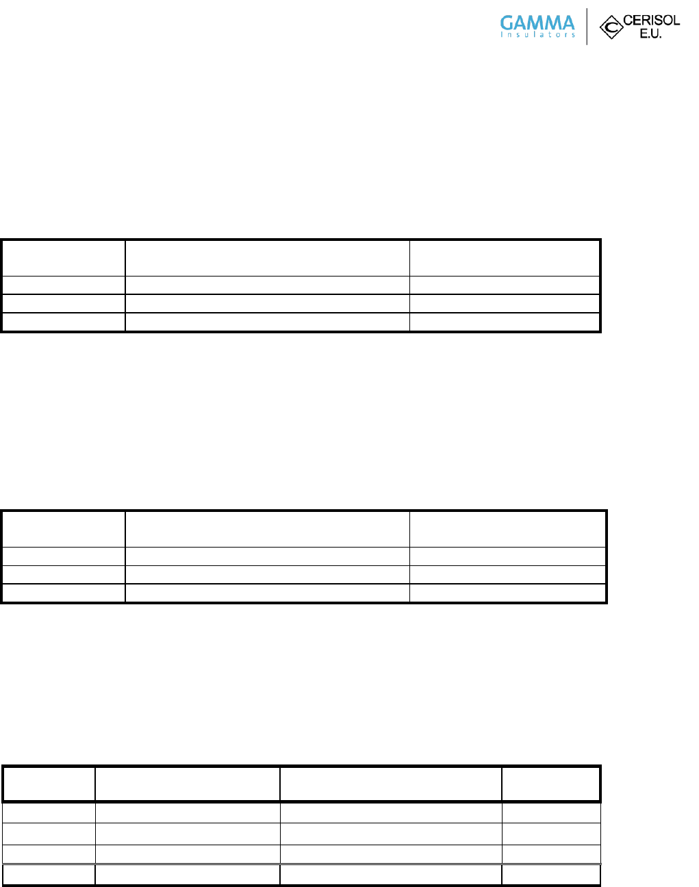
Page 4 of 5
GAMMA-CERISOL Catalog 369ET1300
Design Test Certification
7.2.6 Compression Strength Test
Temperature 68 -71.6 °F (20-22 °C), Minimum failing load 60,000 lbs. (266.880 kN). Smooth increase in load 450 - 900 lbs. /s.
(2 - 4 kN/s), Smooth load up until 89,923 lbs. (400 kN), 3 sec hold on this level and unloading, visual inspection.
Compression Strength Test Results
Sample No.
Load 89,923 lbs. Load (400 kN)
Applied for 3 sec
Result (MFL)
1
Insulator did not fail
Passed
2
Insulator did not fail
Passed
3
Insulator did not fail
Passed
7.2.7 Torsional Strength Test
Temperature during test + 73.4 °F (+ 23 °C), Minimum failing load (MFL) 40,000 lb.-in. (4.52 kNm), Smooth increase in load
265.52- 442.54 lb.-in./s (0.03 – 0.05 kNm/s), Smooth load up until 44,253.73 lb.-in. (5 kNm), 3 sec hold on this level and
unloading, visual inspection.
Torsional Strength Test Results
Sample No.
Torsional moment 44,248 lb.-in. (5 kNm)
Applied for 3 sec
Result (MFL)
1
Insulator did not fail
Passed
2
Insulator did not fail
Passed
3
Insulator did not fail
Passed
7.3.4 Cantilever Strength Test
Temperature during test + 71.6 °F (+ 22 °C), Minimum failing load (MFL) 2,050 lbs. (9.118 kN), Increase in load 9.0 – 15.74 lbs. /s
(0.04 - 0.07 kN/s), smoothly until failure
Cantilever Strength Test Results
Sample No.
Maximum failing load lbs. (kN)
Way of failure
Result (MFL)
1
3,331.67 (14.82)
Failed at bottom part of ceramic core
Passed
2
3,167.56 (14.09)
Failed at bottom part of ceramic core
Passed
3
2,542.59 (11.31)
Failed at bottom part of ceramic core
Passed
Average
3,012.44 (13.4)
Page 5 of 5
GAMMA-CERISOL Catalog 369ET1300
Design Test Certification
7.3.5 Tensile strength
Temperature 68 – 69.8 °F (20-21 °C), Minimum failing load (MFL) 20,000 lbs. (88.960 kN), Increase in load 6.74 – 13.49 lbs./s
(0.3 – 0.6 kN/s), smoothly. Smooth load up until 26,977.07 lbs. (120 kN), 3 sec hold on this level and unloading, visual
inspection.
Tensile Strength Test Results
Sample No.
Load 26,977.07 lbs. (120 kN
Applied for 3 sec
Result (MFL)
1
Insulator did not fail
Passed
2
Insulator did not fail
Passed
3
Insulator did not fail
Passed
Tests performed at EGU HV Laboratory a. s., Test No.10060/D/14, and The Klokner Institute, Report No. 55/14/AL.
All test results contained in this document are held on file under drawing number reference H21369EJ.
__________________________________
Frank Escobar
Chief Engineer, GAMMA Insulators Corporation

Page 1 of 5
Design Test Certification
Material Tested GAMMA-CERISOL Catalog Number 391ST1800
TEST OBJECT: Station Post Insulator
TYPE SPECIFICATION: TR 391
TEST STANDARDS: ANSI C29.9, ANSI C29.1, NEMA No. 107:1993
SCHEDULE OF TESTS
Design Tests, Section 7.2
Page Test Section Description of Test
Electrical Tests
2 7.2.1 Low-frequency Wet Withstand Voltage
3 7.2.2 & 7.2.3 Critical Impulse Flashover Positive & Impulse Withstand Voltage
5 7.2.4 Radio-influence voltage tests
Mechanical Tests
6 7.2.5 Thermal shock test
7 7.2.6 Compression Strength
8 7.2.7 Torsional Strength
Quality Conformance Tests, Section 7.3
9 7.3.4 Cantilever Strength
10 7.3.5 Tensile Strength
All Electrical tests were performed per the requirements of ANSI test standard C29.9:2012, ANSI C29.1:2012, and
NEMA No. 107:1993. All Mechanical tests were performed per the requirements of ANSI test standard
C29.9 - 1983 (R1996), and ANSI C29.1 – 1988 (R2002).
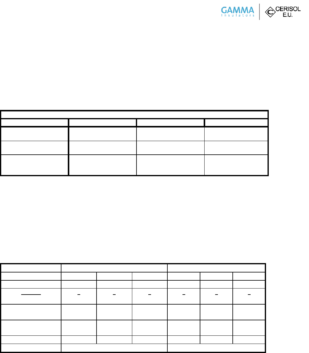
Page 2 of 5
GAMMA-CERISOL Catalog 391ST1800
Design Test Certification
7.2.1 Low-frequency Wet Withstand Voltage
The tests were carried out on three post insulators according to ANSI C29.9, cl. 7.2.1. The rated wet withstand voltage was
applied on each of the tested post insulator for 10 seconds.
The test arrangement was set up according to ANSI C29.1, cl. 3.3
Low-frequency Wet Withstand Voltage Test Results
Station post insulator
Sample No. 1
Sample No.2
Sample No.3
b (in Hg)
t (°F)
29.4
59.2
29.4
59.2
29.4
59.2
r.i. (mm/min)
Rw (Ωm)
5.0
200.0
5.0
200.0
5.0
200.0
VLW (kV)
T (s)
result
710
10
No flashover occurred
710
10
No flashover occurred
710
10
No flashover occurred
No flashover occurred during the test at the rated wet withstand voltage 230 kV specified by ANSI C29.9, Table 2. All test
samples met the requirements. Station post insulator TR 391, Catalog No. 391ST1800 passed low-frequency wet withstand
voltage tests according to ANSI C29.9, cl. 7.2.1.
7.2.2 & 7.2.3 Impulse Withstand Voltage Test and Flashover Voltage
The tests were carried out on the three post insulators according to ANSI C29.9, cl. 7.2.2 and 7.2.3. Three consecutive impulses
of the rated impulse-withstand value of both polarities were applied on each of tested post insulator. The critical impulse
voltages of both polarities were determined by the up and down method with 30 impulses.
The test arrangement was set up according to ANSI C29.1, cl. 3.3
Impulse Withstand Voltage and Flashover Voltage Test Results
Polarity
+
-
Test Sample No.
1
2
3
1
2
3
VIW (kV)
1800
1800
1800
1800
1800
1800
Impulses
Flashovers
3
0
3
0
3
0
3
0
3
0
3
0
b (in Hg)
t (°F)
29.0
60.1
29.0
60.1
29.0
60.1
29.0
60.1
29.0
60.1
29.0
60.1
Kh
Kd
1.001
1.073
1.001
1.073
1.001
1.073
1.001
1.064
1.001
1.064
1.001
1.064
VCRS LI (kV)
2143
2139
2110
2316
2292
2302
VCRSA LI (kV)
2131
2303
No flashover occurred during the test with three impulses at the rated impulse-withstand voltage 1800 kV specified by ANSI
C29.9, Table 2. All test samples met the requirements. Station post insulator TR 391, Catalog No. 391ST1800 passed impulse
withstand voltage tests according to ANSI C29.9, cl. 7.2.3.
The rated critical-impulse flashover voltage 2000 kV is specified by ANSI C29.9, Table 2. The average values of critical-impulse
flashover voltages are higher than 92 percent of the rated critical-impulse flashover voltage, i.e. 1840 kV. All test samples met
the requirements. Station post insulator TR 391, Catalog No. 391ST1800 passed critical-impulse flashover voltage tests
according to ANSI C29.9, cl. 7.2.2.
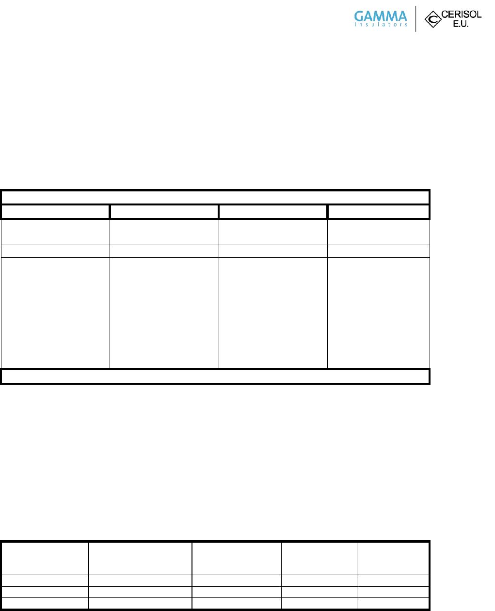
Page 3 of 5
GAMMA-CERISOL Catalog 391ST1800
Design Test Certification
7.2.4 Radio-influence Voltage (RIV) Test
The tests were carried out on three post insulators according to ANSI C29.9, cl. 7.2.4. Radio-influence voltage was measured at
the frequency 1.0 MHz in accordance with circuit diagram in Figure 3 – 3a of NEMA No. 107, Section 3.
The test arrangement was set up according to ANSI C29.1, cl. 4.9.1.
Radio-influence Voltage (RIV) Test Results
Station post insulator
Sample No.1
Sample No.2
Sample No. 3
b (in Hg)
t (°F)
29.03
60.1
29.03
60.1
29.03
60.1
VT (kV)
RIV (µV)
RIV (µV)
RIV (µV)
350
318
286
254
222
190
158
126
0
562
100
56
32
20
5
5
5
5
562
112
63
28
20
5
5
5
5
794
89
56
35
18
5
5
5
5
Rated value: ma. 2000 µV at 318 kV/1.0 MHz
Measured values of radio-influence voltages on post insulators at test voltage 318kV (1MHz) are less than 2000 µV specified by
ANSI C29.9, Table 2. All test samples met the requirements. Station post insulator TR 391, Catalog No. 391ST1800 passed
radio-influence voltage tests according to ANSI C29.9, cl. 7.2.4.
7.2.5 Thermal Shock Test
The test was carried out on three post insulator according to ANSI C 29.9, cl 7.2.5. Each tested post insulator was first
immersed in a hot water bath 150 °F (66 °C) for 10 minutes. Then it was withdrawn and immersed in a cold water bath 39 °F
(4 °C) for 10 minutes. After tenth cycle each post insulator was tested for electrical soundness by low-frequency momentary
flashover voltage test.
Thermal Shock Test Results
10 cycles
(150 °F/ 10 min and 39 F/
10 min)
Low-frequency
Momentary Flashover
Voltage Test
Flashover voltage
(kV)
Result
Test sample #1
No failure
No failure
937
Passed
Test sample #2
No failure
No failure
945
Passed
Test sample #3
No failure
No failure
929
Passed
No Failure occurred during the thermal shock test according to ANSI C29.9, cl. 7.2.5. All test samples met the requirements.
Station post insulator TR 391, Catalog No. 391ST1800 passed thermal shock test according to ANSI C29.9, cl. 7.2.5.
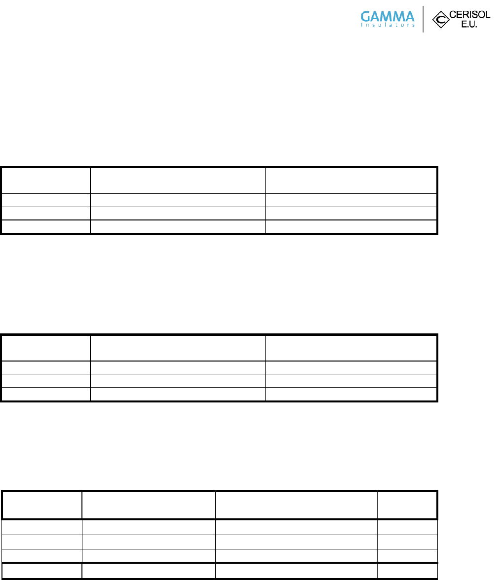
Page 4 of 5
GAMMA-CERISOL Catalog 391ST1800
Design Test Certification
7.2.6 Compression Strength Test
Temperature 68 -71.6 °F (20-22 °C), Minimum failing load 60,000 lbs. (266.880 kN). Smooth increase in load 450 - 900 lbs. /s.
(2 - 4 kN/s), Smooth load up until 89,923 lbs. (400 kN), 3 sec hold on this level and unloading, visual inspection.
Compression Strength Test Results
Sample No.
Load 89,923 (400 kN),
Applied for 3 sec
Result (MFL)
1
Insulator did not fail
Passed
2
Insulator did not fail
Passed
3
Insulator did not fail
Passed
7.2.7 Torsional Strength Test
Temperature during test + 73.4 °F (+ 23 °C), Minimum failing load (MFL) 40,000 lb.-in. (4.52 kNm), Smooth increase in load
265.52- 442.54 lb.-in./s (0.03 – 0.05 kNm/s), Smooth load up until 44,253.72 lb.-in. (5 kNm), 3 sec hold on this level and
unloading, visual inspection.
Torsional Strength Test Results
Sample No.
Torsional moment 44,253.72 lb.-in (5 kNm)
Applied for 3 sec
Result (MFL)
1
Insulator did not fail
Passed
2
Insulator did not fail
Passed
3
Insulator did not fail
Passed
7.3.4 Cantilever Strength Test
Temperature during test + 71.6 °F (+ 22 °C), Minimum failing load (MFL) 1,400 lbs. (6.227 kN), Increase in load
6.74 – 13.49 lbs. /s (0.03 - 0.06 kN/s), smoothly until failure
Cantilever Strength Test Results
Sample
No.
Maximum failing load [kN]
Way of failure
Result
(MFL)
1
9.26
Failed at bottom part of ceramic core
Passed
2
7.04
Failed at bottom part of ceramic core
Passed
3
7.84
Failed at bottom part of ceramic core
Passed
Average
8.05
Page 5 of 5
GAMMA-CERISOL Catalog 391ST1800
Design Test Certification
7.3.5 Tensile strength
Temperature 68 – 69.8 °F (20-21 °C), Minimum failing load (MFL) 20,000 lbs. (88.960 kN), Increase in load 6.74 – 13.49 lbs./s
(0.3 – 0.6 kN/s), smoothly. Smooth load up until 26,977.07 lbs. (120 kN), 3 sec hold on this level and unloading, visual
inspection.
Tensile Strength Test Results
Sample No.
Load 26,977.07 lbs. (120 kN)
Applied for 3 sec
Result (MFL)
1
Insulator did not fail
Passed
2
Insulator did not fail
Passed
3
Insulator did not fail
Passed
Tests performed at EGU HV Laboratory a. s., Test No.10060/E/14, and The Klokner Institute, Report No. 54/14/AL.
All test results contained in this document are held on file under drawing number reference H21391EJ.
__________________________________
Frank Escobar
Chief Engineer, GAMMA Insulators Corporation
