E30D_EMC Report_DC E30D EMC Report DC
2016-04-08
: Pdf E30D Emc Report Dc E30D_EMC__Report_DC CertsReports 207386 ProductFiles
Open the PDF directly: View PDF ![]() .
.
Page Count: 19
Page 1 of 19
EMCTestReport
ReportNo.:AGC03307150201EE01
PRODUCTDESIGNATION:
HDMI Extender by cat-5e/6
BRANDNAME:
CE-LINK
MODELNAME:
E30D
CLIENT :
CE LINK LIMITED
DATEOFISSUE :
Feb.11,2015
STANDARD(S):
EN 55022:2010+AC:2011
EN 55024:2010+AC:2011
REPORTVERSION:
V1.0
AttestationofGlo b a l Compliance(Shenzhen)Co.,Ltd
CAUTION:
Thisreportshallnotbereproducedexceptinfullwithoutthewrittenpermissionofthe
testlaboratoryandshallnotbequotedoutofcontext.
Report No.: AGC03307150201EE01
Page 2 of 19
Report Revise Record
Report Version Revise Time Issued Date Valid Version Notes
V1.0 / Feb.11,2015 Valid Original Report

Report No.: AGC03307150201EE01
Page 3 of 19
TABLE OF CONTENTS
1. VERIFICATION OF CONFORMITY ...................................................................................... 4
2. SYSTEM DESCRIPTION ...................................................................................................... 5
3. MEASUREMENT UNCERTAINTY........................................................................................ 5
4. PRODUCT INFORMATION .................................................................................................. 6
5. SUPPORT EQUIPMENT ....................................................................................................... 7
6. TEST FACILITY .................................................................................................................... 8
7. EN 55022 RADIATED EMISSION TEST .............................................................................. 9
7.1. LIMITS OF RADIATED DISTURBANCES ...................................................................... 9
7.2. BLOCK DIAGRAM OF TEST SETUP ............................................................................ 9
7.3. PROCEDURE OF RADIATED EMISSION TEST ......................................................... 10
7.4. TEST RESULT OF RADIATED EMISSION TEST ......................................................... 11
8. IEC 61000-4-2 ESD IMMUNITY TEST ................................................................................ 13
8.1. BLOCK DIAGRAM OF TEST SETUP .......................................................................... 13
8.2. TEST PROCEDURE .................................................................................................... 14
8.3. PERFORMANCE & RESULT ....................................................................................... 14
9. IEC 61000-4-3 RS IMMUNITY TEST .................................................................................. 15
9.1. BLOCK DIAGRAM OF TEST SETUP .......................................................................... 15
9.2. TEST PROCEDURE .................................................................................................... 16
9.3. PERFORMANCE & RESULT ....................................................................................... 16
APPENDIX A: PHOTOGRAPHS OF TEST SETUP ............................................................... 17
APPENDIX B: PHOTOGRAPHS OF EUT .............................................................................. 18
Report No.: AGC03307150201EE01
Page 4 of 19
1. VERIFICATION OF CONFORMITY
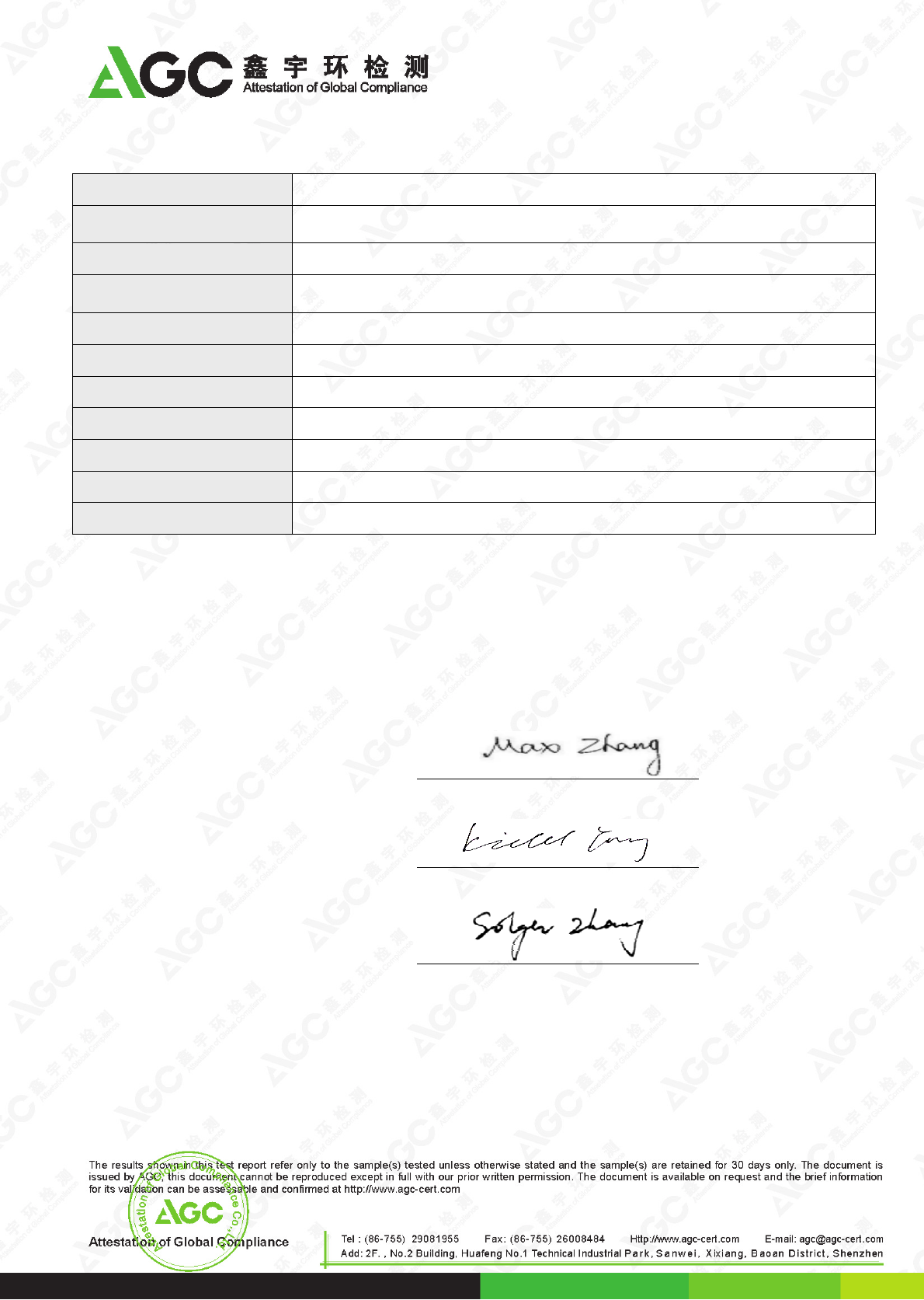
Applicant CE LINK LIMITED
Address Building G, Licheng Technology Industrial Zone, Gonghe Village, Shajing Town,
Shenzhen City, China
Manufacturer CE LINK LIMITED
Address Building G, Licheng Technology Industrial Zone, Gonghe Village, Shajing Town,
Shenzhen City, China
Product Designation HDMI Extender by cat-5e/6
Brand Name CE-LINK
Test Model E30D
Date of test Feb.7~Feb.10, 2015
Deviation None
Condition of Test Sample Normal
Report Template AGCRT-EC-IT/DC(2013-03-01)
The above equipment was tested by Attestation of Global Compliance (Shenzhen) Co., Ltd. for compliance with
the requirements set forth in the Technical Standards mentioned above. This said equipment in the
configuration described in this report shows the maximum emission levels emanating from equipment and the
level of the immunity endurance of the equipment are within the compliance requirements.
The test results of this report relate only to the tested sample identified in this report.
Prepared By
Max Zhang Feb.11,2015
Checked By
Kidd Yang Feb.11,2015
Authorized By
Solger Zhang Feb.11,2015

Report No.: AGC03307150201EE01
Page 5 of 19
2. SYSTEM DESCRIPTION
1. Connect EUT and peripheral devices (if need)
2. Power on the EUT, The EUT begins to work.
3. Make sure the EUT works normally during the test.
3. MEASUREMENT UNCERTAINTY
The uncertainty is calculated using the methods suggested in the “Guide to the Expression of Uncertainty in
measurement” (GUM) published by ISO.
- Uncertainty of Radiated Emission, Uc = ±3.2 dB
Report No.: AGC03307150201EE01
Page 6 of 19
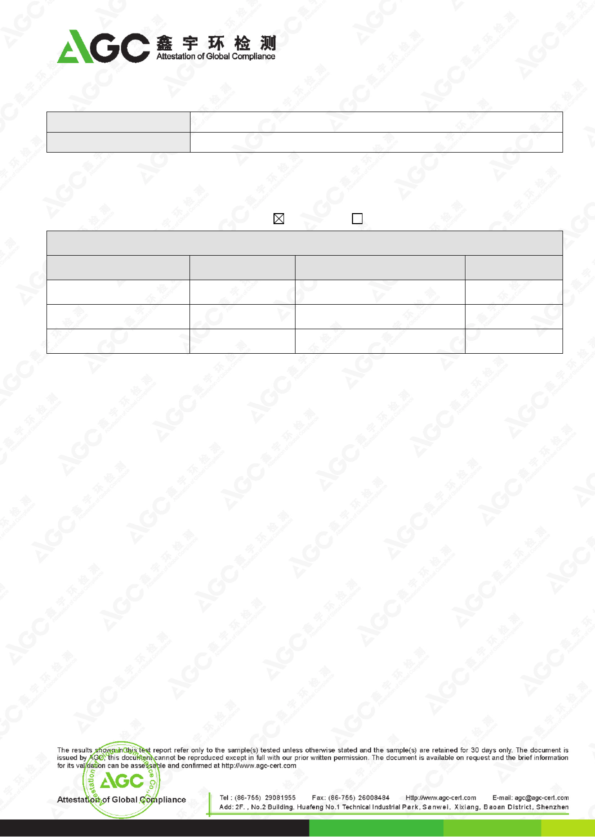
4. PRODUCT INFORMATION
Housing Type Plastic and metal
EUT Rating Voltage DC 5V Supply By PC
I/O Port Information ( Applicable Not Applicable)
I/O Port of EUT
I/O Port Type Q’TY Cable Tested with
HDMI input port 1 0.25m, shielded 1
DDC output port 1 0 1
TMDS output port 1 0 1
Report No.: AGC03307150201EE01
Page 7 of 19
5. SUPPORT EQUIPMENT
Device Type Manufacturer Model Name Serial No. Data Cable Power
Cable
PC Apple MB990CH/A N/A N/A N/A
Note:
All the above equipment/cables were placed in worse case positions to maximize emission signals during
emission test.
Report No.: AGC03307150201EE01
Page 8 of 19
6. TEST FACILITY
TEST EQUIPMENT OF RADIATED EMISSION TEST
Equipment Manufacturer Model S/N Cal. Date Cal. Due
TEST RECEIVER R&S ESPI 101206 2014.07.25 2015.07.25
ANTENNA SCHWARZBE
CK VULB9168 494 2014.08.17 2015.08.17
POSITIONING
CONTROLLER MF MF-7802 MF780208285 -- --
TEST EQUIPMENT OF ESD TEST
Equipment Manufacturer Model S/N Cal. Date Cal. Due
ESD Simulator Schaffner NSG 438 782 2014.07.30 2015.07.30
TEST EQUIPMENT OF RS IMMUNITY TEST
Description Manufacturer Model Identifier Cal. Date Cal. Due
SIGNAL
GENERATOR R&S E4421B 102525 2014.07.25 2015.07.25
ANTENNA SCHWARZBEC
K VULB9168 VULB9168-494 2014.08.17 2015.08.17
POWER SENSOR R&S URV5-Z4 100124 2014.07.25 2015.07.25
POWER METER R&S NRVD 832378/027 2014.07.25 2015.07.25
POWER AMPLIFIER KALMUS 7100C N/A 2014.07.25 2015.07.25
RF AMPLIFIER Milmega AS01004-5
5_55 1004793 2014.07.25 2015.07.25
HORN ANTENNA ETS LINDGREN 3117 N/A 2013.08.17 2015.08.17
Site Attestation of Global Compliance (Shenzhen) Co., Ltd
Location 2/F., Building 2, No.1-No.4, Chaxi Sanwei Technical Industrial Park, Gushu, Xixiang,
Bao'an District, Shenzhen, Guangdong, China
Report No.: AGC03307150201EE01
Page 9 of 19
7. EN 55022 RADIATED EMISSION TEST
7.1. LIMITS OF RADIATED DISTURBANCES
AT 10M DISTANCES
Frequency
(MHz) Distance
(m) Maximum Field Strength Limit
(dBuV/m Q.P.)
30-230 10 30.00
230-1000 10 37.00
AT 3M DISTANCES
Frequency
(MHz) Distance
(m) Maximum Field Strength Limit
(dBuV/m Q.P.)
30-230 3 40.00
230-1000 3 47.00
Note: The lower limit shall apply at the transition frequency.
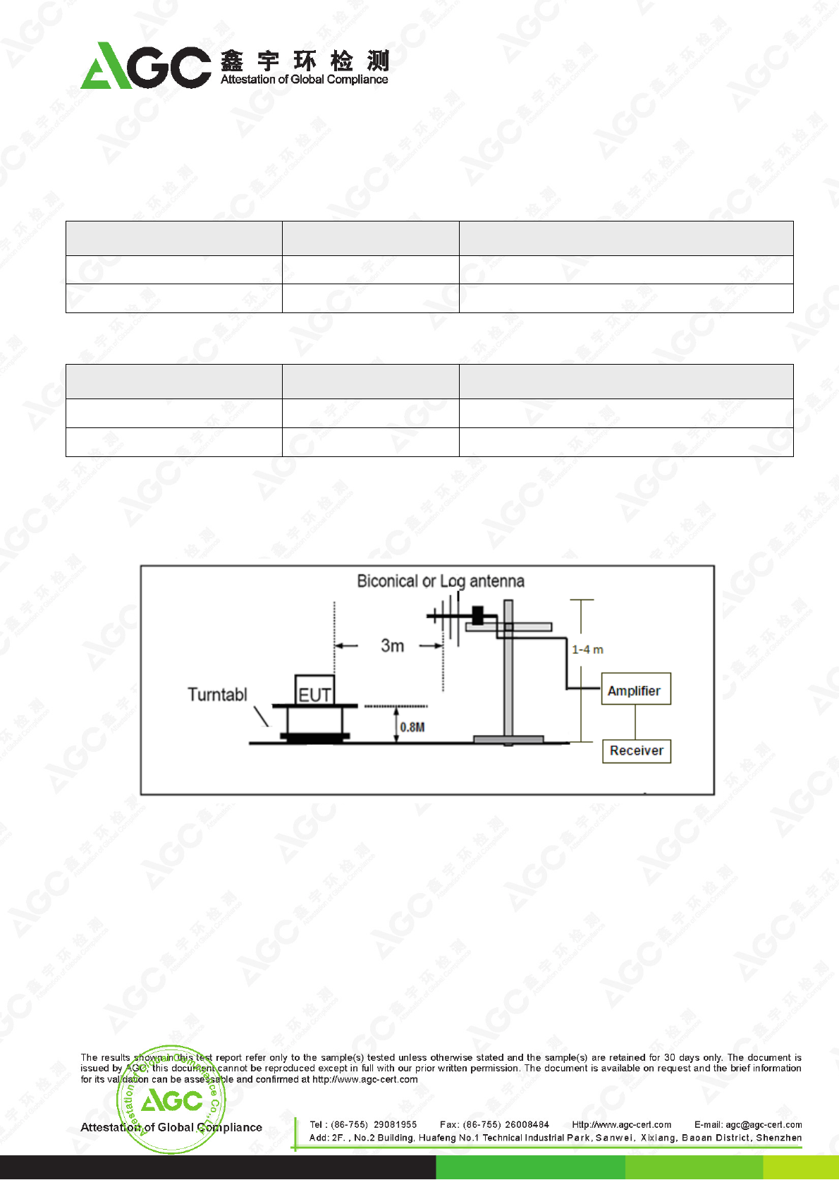
7.2. BLOCK DIAGRAM OF TEST SETUP
System Diagram of Connections between EUT and Simulators

Report No.: AGC03307150201EE01
Page 10 of 19
7.3. PROCEDURE OF RADIATED EMISSION TEST
(1) The equipment was set up as per the test configuration to simulate typical actual usage per the user’s
manual. When the EUT is a tabletop system, a wooden turntable with a height of 0.8 meters is used which
is placed on the ground plane as per EN 55022 (see Test Facility for the dimensions of the ground plane
used).When the EUT is a floor-standing equipment, it is placed on the ground plane which has a 3-12 mm
non-conductive covering to insulate the EUT from the ground plane.
(2) Support equipment, if needed, was placed as per EN 55022.
(3) All I/O cables were positioned to simulate typical actual usage as per EN 55022.
(4) The EUT was connected to PC and displayer. All support equipments received AC230V/50Hz power from
socket under the turntable, if any.
(5) The antenna was placed at 3 meter away from the EUT as stated in EN 55022. The antenna connected to
the Analyzer via a cable and at times a pre-amplifier would be used.
(6) The Analyzer / Receiver quickly scanned from 30MHz to 1000MHz. The EUT test program was started.
Emissions were scanned and measured rotating the EUT to 360 degrees and positioning the antenna 1 to
4 meters above the ground plane, in both the vertical and the horizontal polarization, to maximize the
emission reading level.
(7) The test mode(s) were scanned during the test:
(8) Recorded at least the six highest emissions. Emission frequency, amplitude, antenna position, polarization
and turntable position were recorded into a computer in which correction factors were used to calculate the
emission level and compare reading to the applicable limit and Q.P./Peak reading is presented.
Report No.: AGC03307150201EE01
Page 11 of 19
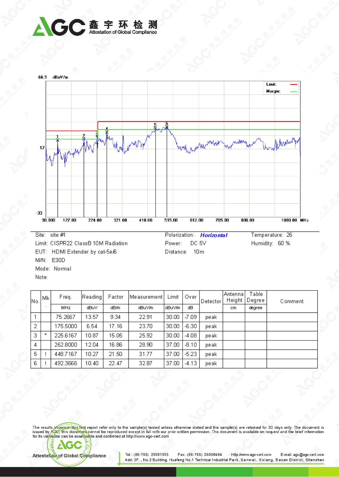
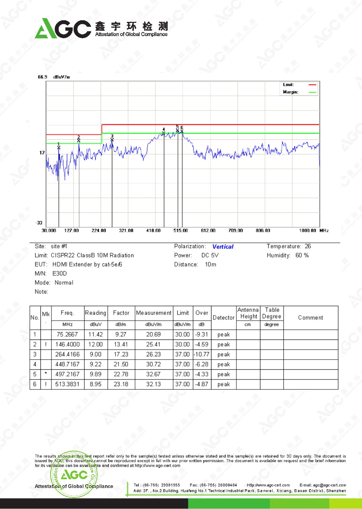
7.4. TEST RESULT OF RADIATED EMISSION TEST
Radiated Emission Test at 3m Distance-Horizontal
RESULT: PASS
Report No.: AGC03307150201EE01
Page 12 of 19
Radiated Emission Test at 3m Distance-Vertical
RESULT: PASS
Report No.: AGC03307150201EE01
Page 13 of 19
8. IEC 61000-4-2 ESD IMMUNITY TEST
ELECTROSTATIC DISCHARGE (ESD) IMMUNITY TEST
Port Enclosure
Basic Standard IEC 61000-4-2
Test Level ± 8.0 kV (Air Discharge)
± 4.0 kV (Contact Discharge)
± 4.0 kV (Indirect Discharge)
Standard require B
Tester Max
Temperature 20oC
Humidity 50%
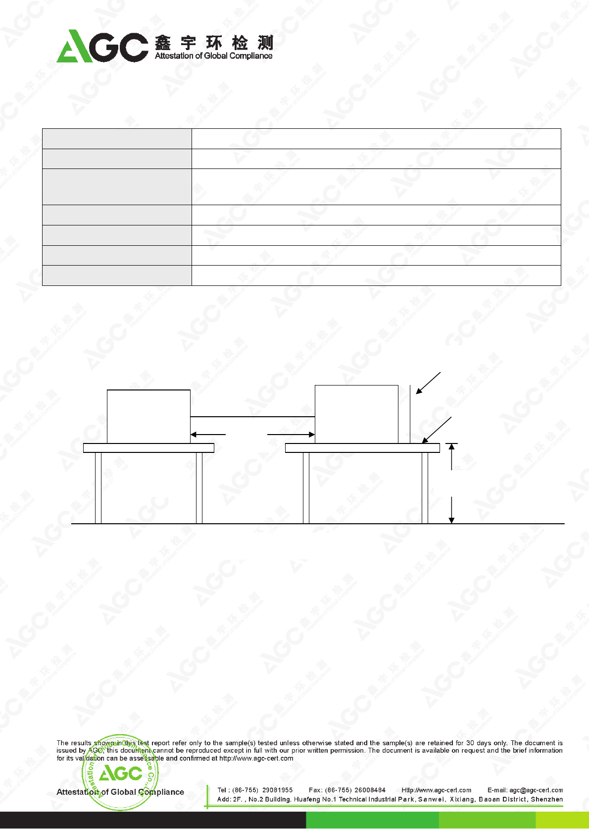
8.1. BLOCK DIAGRAM OF TEST SETUP
(The 470 k ohm resistors are installed per standard requirement)
Ground Reference Plane
Wooden Table
Support units
EUT&
Support
Units
VCP
HCP
>1m
0.8m
Report No.: AGC03307150201EE01
Page 14 of 19
8.2. TEST PROCEDURE
The EUT was located 0.1 m minimum from all side of the HCP.
The support units were located 1 m minimum away from the EUT.
EUT worked with resistance load, and make sure EUT worked normally.
Active the communication function if the EUT with such port(s).
As per the requirement of EN 55024; applying direct contact discharge at the sides other than front of EUT at
minimum 50 discharges (25 positive and 25 negative) if applicable, can’t be applied direct contact discharge
side of EUT then the indirect discharge shall be applied. One of the test points shall be subjected to at least 50
indirect discharge (contact) to the front edge of horizontal coupling plane.
Other parts of EUT where it is not possible to perform contact discharge then selecting appropriate points of
EUT for air discharge, a minimum of 10 single air discharges shall be applied.
The application of ESD to the contact of open connectors is not required.
Note: As per the A2 to IEC 61000-4-2, a bleed resistor cable is connected between the EUT and HCP during the
test.
The electrostatic discharges were applied as follows:
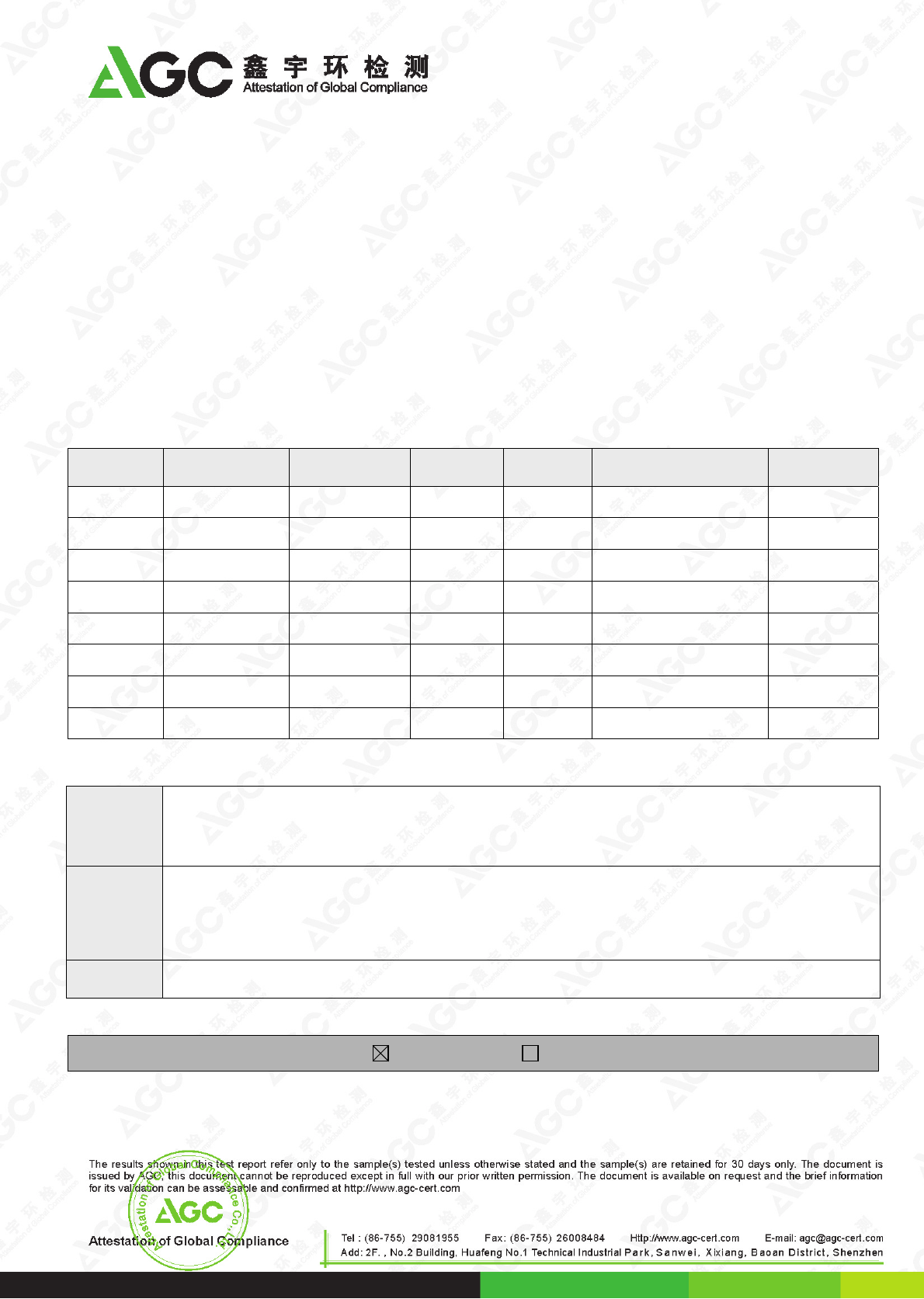
Voltage Coupling Test Performance Result
±4kV Contact Discharge No function loss A
±4kV Indirect Discharge HCP (Front) No function loss A
±4kV Indirect Discharge HCP (Left) No function loss A
±4kV Indirect Discharge HCP (Back) No function loss A
±4kV Indirect Discharge HCP (Right) No function loss A
±4kV Indirect Discharge VCP (Front) No function loss A
±4kV Indirect Discharge VCP (Left) No function loss A
±4kV Indirect Discharge VCP (Back) No function loss A
±4kV Indirect Discharge VCP (Right) No function loss A
±8kV Air Discharge No function loss A
8.3. PERFORMANCE & RESULT
Criteria A:
The apparatus continues to operate as intended. No degradation of performance or loss
of function is allowed below a performance level specified by the manufacturer, when the
apparatus is used as intended. In some cases the performance level may be replaced by
a permissible loss of performance.
Criteria B:
The apparatus continues to operate as intended after the test. No degradation of
performance or loss of function is allowed below a performance level specified by the
manufacturer, when the apparatus is used as intended. In some cases the performance
level may be replaced by a permissible loss of performance. During the test, degradation
of performance is however allowed.
Criteria C: Temporary loss of function is allowed, provided the functions self recoverable or can be
restored by the operation of controls.
PASS FAIL
Report No.: AGC03307150201EE01
Page 15 of 19
9. IEC 61000-4-3 RS IMMUNITY TEST
RADIATED ELECTROMAGNETIC FIELD IMMUNITY TEST
Port Enclosure
Basic Standard IEC 61000-4-3
Test Level: 3V/m with 80% AM. 1kHz Modulation.
Standard require A
Tester Max
Temperature 25oC
Humidity 55%
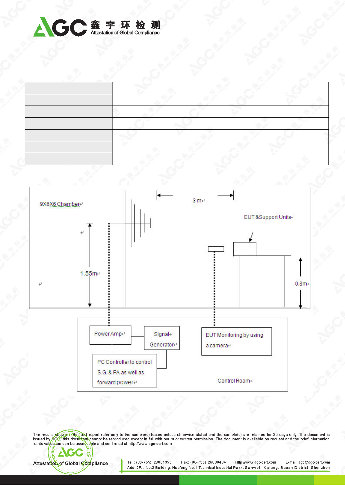
9.1. BLOCK DIAGRAM OF TEST SETUP
Report No.: AGC03307150201EE01
Page 16 of 19
9.2. TEST PROCEDURE
The EUT was located at the edge of supporting table keep 3 meter away from transmitting antenna, it just the
calibrated square area of field uniformity. The support units were located outside of the uniformity area, but the
cable(s) connected with EUT were exposed to the calibrated field as per IEC 61000-4-3.
EUT worked with resistance load, and make sure EUT worked normally.
Setting the testing parameters of RS test software per IEC 61000-4-3.
Performing the test at each side of with specified level (3V/m) at 1% steps and test frequency from 80MHz to
1000MHz
Recording the test result in following table.
IEC 61000-4-3 Final test conditions:
Test level: 3V/m
Steps: 1 % of fundamental
Dwell Time: 1 sec
Range
(MHz) Field Modulation Polarity Position Test Performance Result
80-1000 3V/m AM H Front No function loss A
80-1000 3V/m AM H Left No function loss A
80-1000 3V/m AM H Back No function loss A
80-1000 3V/m AM H Right No function loss A
80-1000 3V/m AM V Front No function loss A
80-1000 3V/m AM V Left No function loss A
80-1000 3V/m AM V Back No function loss A
80-1000 3V/m AM V Right No function loss A
9.3. PERFORMANCE & RESULT
Criteria A:
The apparatus continues to operate as intended. No degradation of performance or loss of
function is allowed below a performance level specified by the manufacturer, when the apparatus
is used as intended. In some cases the performance level may be replaced by a permissible loss
of performance.
Criteria B:
The apparatus continues to operate as intended after the test. No degradation of performance or
loss of function is allowed below a performance level specified by the manufacturer, when the
apparatus is used as intended. In some cases the performance level may be replaced by a
permissible loss of performance. During the test, degradation of performance is however
allowed.
Criteria C: Temporary loss of function is allowed, provided the functions self recoverable or can be restored
by the operation of controls.
PASS FAIL
Report No.: AGC03307150201EE01
Page 17 of 19
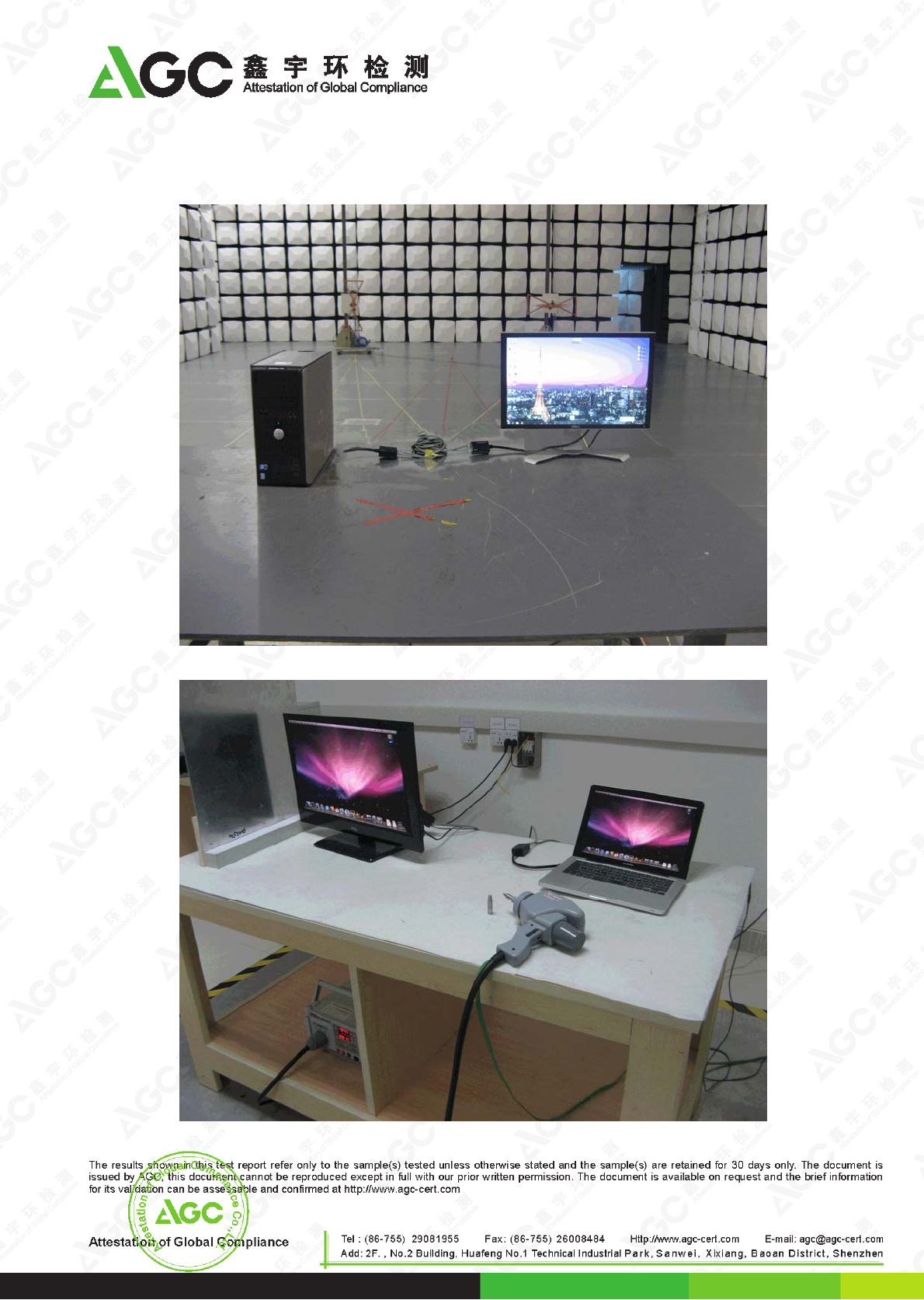
APPENDIX A: PHOTOGRAPHS OF TEST SETUP
EN 55022 RADIATED EMISSION TEST SETUP
IEC 61000-4-2 ESD IMMUNITY TEST SETUP
Report No.: AGC03307150201EE01
Page 18 of 19
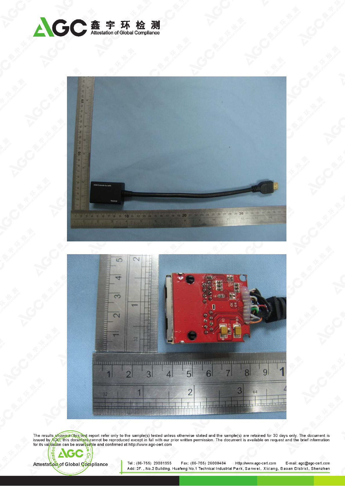
APPENDIX B: PHOTOGRAPHS OF EUT
EXTERNAL VIEW OF EUT
INTERNAL VIEW OF EUT-1
Report No.: AGC03307150201EE01
Page 19 of 19
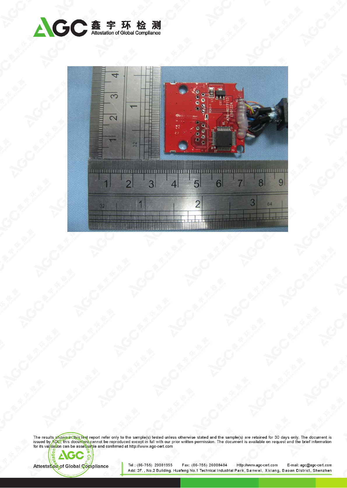
INTERNAL VIEW OF EUT-2
-----END OF REPORT------
