LCS1506010003E EMC Reportlcs—直流 Report
Emc Report EMC_Report EMC_Report CertsReports 162296 ProductFiles assets.mhint
2016-04-05
: Pdf Emc Report EMC_Report CertsReports 162302 ProductFiles
Open the PDF directly: View PDF ![]() .
.
Page Count: 29

SHENZHEN LCS COMPLIANCE TESTING LABORATORY LTD. Report No.: LCS1506010003E
This report shall not be reproduced except in full, without the written approval of Shenzhen LCS Compliance Testing Laboratory Ltd.
Page 1 of 29
EMC TEST REPORT
For
Magicview Technology Co., Ltd.
USB HUB
Model No.: U3H342, 162296, 162302
Prepared for :
Magicview Technology Co., Ltd.
Address :
No. 27-3, Sec. 3, Xinyi Rd. Da-An Dist., Taipei City
10657 Taiwan
Prepared by
:
Shenzhen LCS Compliance Testing Laboratory Ltd.
Address :
1/F., Xingyuan Industrial Park, Tongda Road, Bao’an
Avenue, Bao’an District, Shenzhen, Guangdong, China
Tel
:
(+86)755-82591330
Fax :
(+86)755-82591332
Web
:
www.LCS-cert.com
Mail :
webmaster@LCS-cert.com
Date of receipt of test sample
:
May 29, 2015
Number of tested samples :
1
Serial number :
Prototype
Date of Test :
May 29, 2015 – June 04, 2015
Date of Report :
June 04, 2015
SHENZHEN LCS COMPLIANCE TESTING LABORATORY LTD. Report No.: LCS1506010003E
This report shall not be reproduced except in full, without the written approval of Shenzhen LCS Compliance Testing Laboratory Ltd.
Page 2 of 29
EMC TEST REPORT
EN 55022: 2010
Information technology equipment-Radio disturbance characteristics-Limits of measurement
EN 55024: 2010
Information technology equipment-Immunity characteristics-Limits and methods of measurement of
measurement
Report Reference No. .............. :
LCS1506010003E
Date of Issue................................ :
June 04, 2015
Testing Laboratory Name ......... :
Shenzhen LCS Compliance Testing Laboratory Ltd.
Address........................................ :
1/F., Xingyuan Industrial Park, Tongda Road,
Bao
’
an Avenue,
Bao
’
an District, Shenzhen, Guangdong, China
Testing Location/ Procedure ....... :
Full application of Harmonised standards
■
Partial application of Harmonised standards □
Other standard testing method □
Applicant’s Name ...................... :
Magicview Technology Co., Ltd.
Address........................................ :
No. 27
-
3, Sec. 3, Xinyi Rd. Da
-
An Dist., Taipei City 10657
Taiwan
Test Specification:
Standard ...................................... :
EN 55022: 2010
EN 55024: 2010
Test Report Form No. ............... :
LCSEMC-1.0
TRF Originator ............................ :
Shenzhen LCS Compliance Testing Laboratory Ltd.
Master TRF ................................. :
Dated 2011-03
SHENZHEN LCS COMPLIANCE TESTING LABORATORY LTD. All rights reserved.
This publication may be reproduced in whole or in part for non-
commercial purposes as long as the
SHENZHEN LCS COMPLIANCE TESTING LABORATORY LTD.
is acknowledged as copyright
owner and source of the material.
SHENZHEN LCS COMPLIANCE TESTING LABORATORY
LTD. takes no respon
sibility for and will not assume liability for damages resulting from the reader's
interpretation of the reproduced material due to its placement and context.
Test Item Description. ............... :
USB HUB
Trade Mark .................................. :
N/A
Model/ Type Reference ............... :
U3H342
Ratings ........................................ :
DC 5V
Result ........................................ :
Positive
Compiled by:
Supervised by:
Approved by:
Elan Liu/ File administrators
Danny Huang/ Technique principal
Gavin Liang/ Manager
SHENZHEN LCS COMPLIANCE TESTING LABORATORY LTD. Report No.: LCS1506010003E
This report shall not be reproduced except in full, without the written approval of Shenzhen LCS Compliance Testing Laboratory Ltd.
Page 3 of 29
EMC -- TEST REPORT
Test Result according to the standards on page 6:
Positive
The test report merely corresponds to the test sample.
It is not permitted to copy extracts of these test result without the written permission of the test
laboratory.
Test Report No. :
LCS1506010003E
June 04, 2015
Date of issue
Type / Model...........................
:
U3H342
EUT.........................................
:
USB HUB
Applicant...............................
:
Magicview Technology Co., Ltd.
Address...................................
.
:
No. 27-3, Sec. 3, Xinyi Rd. Da-An Dist., Taipei City 10657
Taiwan
Telephone................................
:
/
Fax..........................................
:
/
Manufacturer.........................
:
Magicview Technology Co., Ltd.
Address...................................
:
No. 27-3, Sec. 3, Xinyi Rd. Da-An Dist., Taipei City 10657
Taiwan
Telephone................................
:
/
Fax..........................................
:
/
Factory...................................
:
Magicview Technology Co., Ltd.
Address...................................
:
No. 27-3, Sec. 3, Xinyi Rd. Da-An Dist., Taipei City 10657
Taiwan
Telephone................................
:
/
Fax..........................................
:
/

SHENZHEN LCS COMPLIANCE TESTING LABORATORY LTD. Report No.: LCS1506010003E
This report shall not be reproduced except in full, without the written approval of Shenzhen LCS Compliance Testing Laboratory Ltd.
Page 4 of 29
TABLE OF CONTENT
Test Report Description
Page
1. SUMMARY OF STANDARDS AND RESULTS .......................................................................................... 6
1.1.Description of Standards and Results ....................................................................................................... 6
1.2.Description of Performance Criteria ........................................................................................................ 7
2. GENERAL INFORMATION......................................................................................................................... 8
2.1.Description of Device (EUT) ................................................................................................................... 8
2.2.Description of Test Facility ...................................................................................................................... 8
2.3.Statement of the measurement uncertainty ............................................................................................... 8
2.4.Measurement Uncertainty ........................................................................................................................ 9
3. measuring Devices and test equipment ....................................................................................................... 10
3.1.Conducted Disturbance .......................................................................................................................... 10
3.2.Disturbance Power ................................................................................................................................. 10
3.3.Radiated Electromagnetic Disturbance .................................................................................................. 10
3.4.Radiated Disturbance (Electric Field) .................................................................................................... 10
3.5.Harmonic Current ................................................................................................................................... 10
3.6.Voltage fluctuation and Flicker .............................................................................................................. 10
3.7.Electrostatic Discharge ........................................................................................................................... 10
3.8.RF Field Strength Susceptibility ............................................................................................................ 11
3.9.Electrical Fast Transient/Burst ............................................................................................................... 11
3.10.Surge .................................................................................................................................................... 11
3.11.Conducted Susceptibility ...................................................................................................................... 11
3.12.Power Frequency Magnetic Field Susceptibility .................................................................................. 11
3.13.Voltage Dips ......................................................................................................................................... 11
3.14.Voltage Short Interruptions .................................................................................................................. 11
4. RADIATED EMISSION MEASUREMENT .............................................................................................. 12
4.1.Block Diagram of Test Setup ................................................................................................................. 12
4.2.Measuring Standard ................................................................................................................................ 12
4.3.Radiated Emission Limits ...................................................................................................................... 12
4.4.EUT Configuration on Test .................................................................................................................... 13
4.5.Operating Condition of EUT .................................................................................................................. 13
4.6.Test Procedure ........................................................................................................................................ 13
4.7.Test Results ............................................................................................................................................ 13
5. ELECTROSTATIC DISCHARGE IMMUNITY TEST ............................................................................ 15
5.1.Block Diagram of Test Setup ................................................................................................................. 15
5.2.Test Standard .......................................................................................................................................... 15
5.3.Severity Levels and Performance Criterion ........................................................................................... 15
5.4.EUT Configuration on Test .................................................................................................................... 15
5.5.Operating Condition of EUT .................................................................................................................. 15
5.6.Test Procedure ........................................................................................................................................ 16
5.7.Test Results ............................................................................................................................................ 16
6. RF FIELD STRENGTH SUSCEPTIBILITY TEST .................................................................................. 18
6.1.Block Diagram of Test ........................................................................................................................... 18
6.2.Test Standard .......................................................................................................................................... 18
6.3.Severity Levels and Performance Criterion ........................................................................................... 18
6.4.EUT Configuration on Test .................................................................................................................... 19
6.5.Operating Condition of EUT .................................................................................................................. 19
6.6.Test Procedure ........................................................................................................................................ 19
6.7.Test Results ............................................................................................................................................ 19
7. MAGNETIC FIELD SUSCEPTIBILITY TEST ....................................................................................... 21
7.1.Block Diagram of Test Setup ................................................................................................................. 21
7.2.Test Standard .......................................................................................................................................... 21
7.3.Severity Levels and Performance Criterion ........................................................................................... 21
7.4.EUT Configuration on Test .................................................................................................................... 21
SHENZHEN LCS COMPLIANCE TESTING LABORATORY LTD. Report No.: LCS1506010003E
This report shall not be reproduced except in full, without the written approval of Shenzhen LCS Compliance Testing Laboratory Ltd.
Page 5 of 29
7.5.Test Procedure ........................................................................................................................................ 22
7.6.Test Results ............................................................................................................................................ 22
8. PHOTOGRAPH ............................................................................................................................................ 24
8.1.Photo of Radiated Measurement ............................................................................................................ 24
8.2.Photo of Electrostatic Discharge Test ..................................................................................................... 24
8.3.Photo of Magnetic Field Immunity Test ................................................................................................. 25
9. EXTERNAL AND INTERNAL PHOTOS OF THE EUT ......................................................................... 26
SHENZHEN LCS COMPLIANCE TESTING LABORATORY LTD. Report No.: LCS1506010003E
This report shall not be reproduced except in full, without the written approval of Shenzhen LCS Compliance Testing Laboratory Ltd.
Page 6 of 29
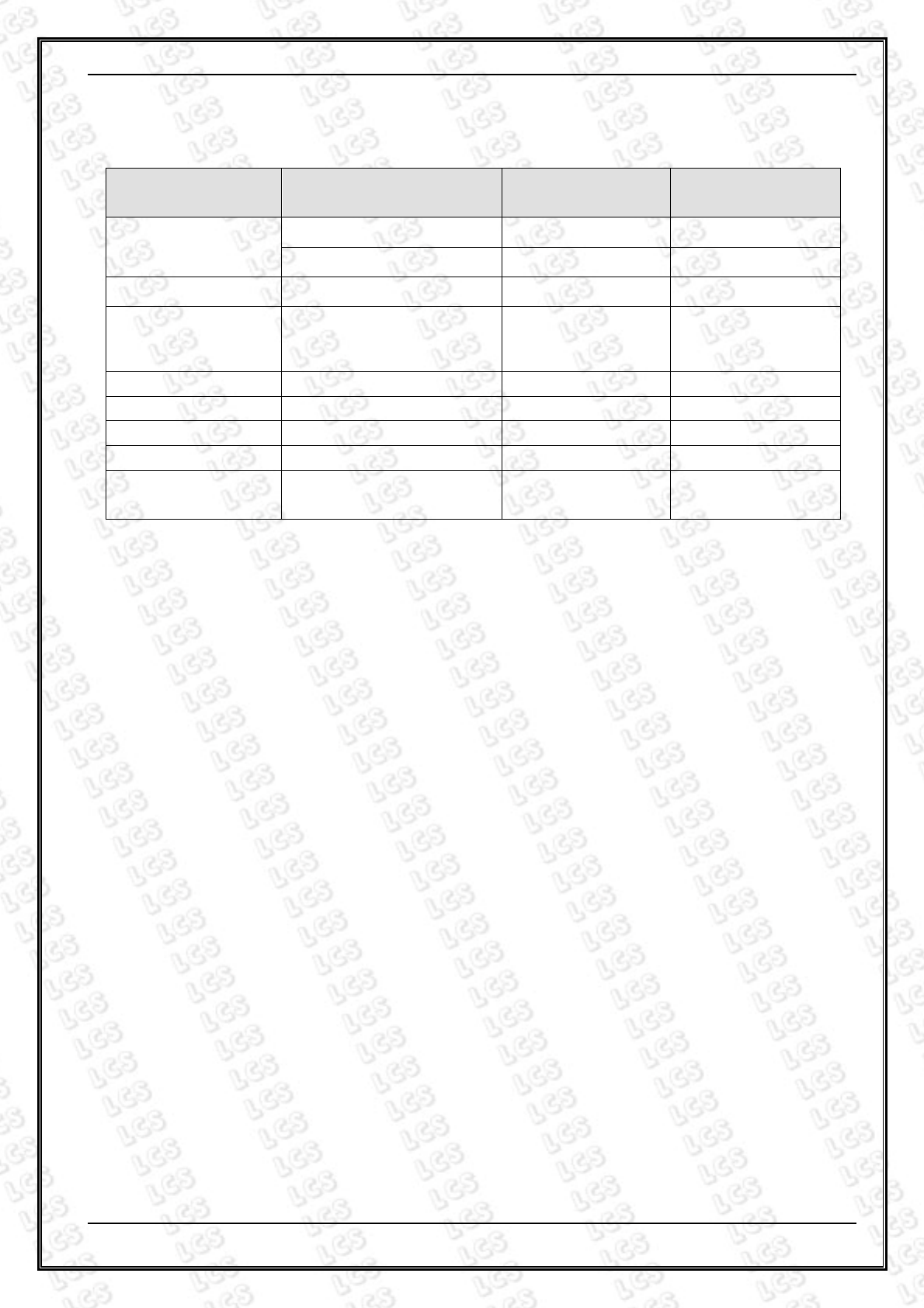
1. SUMMARY OF STANDARDS AND RESULTS
1.1.Description of Standards and Results
The EUT have been tested according to the applicable standards as referenced below.
EMISSION (EN 55022: 2010)
Description of Test Item Standard Limits Results
Conducted disturbance
at mains terminals EN 55022: 2010 Class B
N/A
Conducted disturbance at
telecommunication port EN 55022: 2010 Class B
N/A
Radiated disturbance EN 55022: 2010 Class B
PASS
Harmonic current emissions EN 61000-3-2: 2014 Class A
N/A
Voltage fluctuations & flicker EN 61000-3-3: 2012 -------- N/A
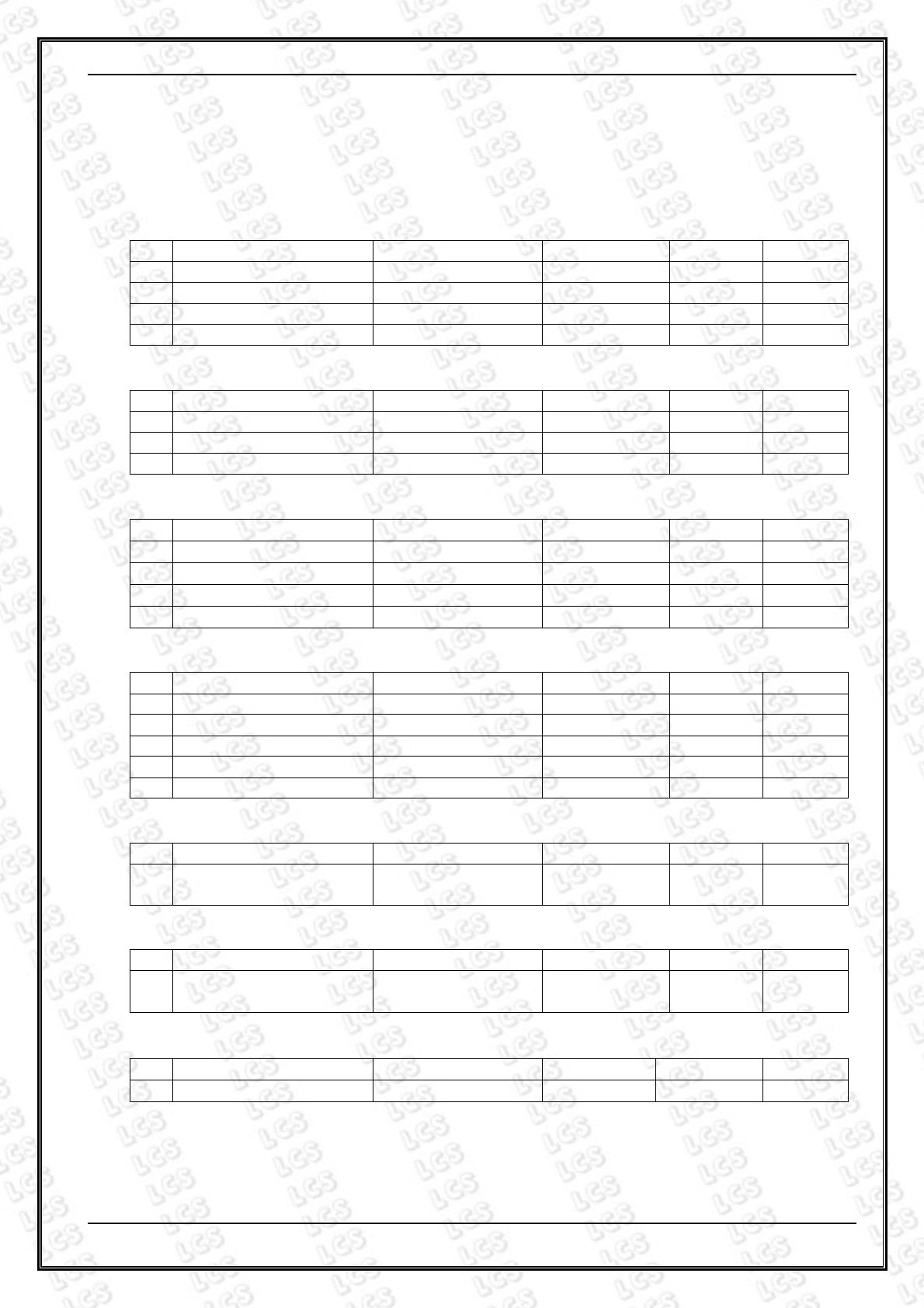
IMMUNITY(EN 55024: 2010)
Description of Test Item Basic Standard
Performance
Criteria Results
Electrostatic discharge (ESD) EN 61000-4-2: 2009 B PASS
Radio-frequency,
Continuous radiated disturbance EN 61000-4-3: 2006+A1: 2008+A2 2010 A PASS
Electrical fast transient (EFT) EN 61000-4-4: 2012 B N/A
Surge (Input a.c. power ports)
EN 61000-4-5: 2014
B N/A
Surge (Telecommunication ports)
B N/A
Radio-frequency,
Continuous conducted disturbance
EN 61000-4-6: 2014 A N/A
Power frequency magnetic field EN 61000-4-8: 2010 A PASS
Voltage dips, >95% reduction
EN 61000-4-11: 2004
B N/A
Voltage dips,
30% reduction B N/A
Voltage interruptions
C N/A
N/A is an abbreviation for Not Applicable.

SHENZHEN LCS COMPLIANCE TESTING LABORATORY LTD. Report No.: LCS1506010003E
This report shall not be reproduced except in full, without the written approval of Shenzhen LCS Compliance Testing Laboratory Ltd.
Page 7 of 29
1.2.Description of Performance Criteria
General Performance Criteria
Examples of functions defined by the manufacturer to be evaluated during testing
include, but are not limited to, the following:
─ essential operational modes and states;
─ tests of all peripheral access (hard disks, floppy disks, printers, keyboard,
mouse, etc.);
─ quality of software execution;
─ quality of data display and transmission;
─ quality of speech transmission.
1.2.1.Performance criterion A
The equipment shall continue to operate as intended without operator
intervention. No degradation of performance or loss of function is allowed below
a performance level specified by the manufacture when the equipment is used as
intended. The performance level may be replaced by a permissible loss of
performance. If the minimum performance level or the permissible performance
loss is not specified by the manufacturer, then either of these may be deriver
from the product description and documentation, and by what the user may
reasonably expect from the equipment if used as intended.
1.2.2.Performance criterion B
After the test, the equipment shall continue to operate as intended without
operator intervention. No degradation of performance or loss of function is
allowed, after the application of the phenomena below a performance level
specified by the manufacture, when the equipment is used as intended. The
performance level may be replaced by a permissible loss of performance.
During the test, degradation of performance is allowed. However, no change of
operation state or stored data is allowed to persist after the test.
If the minimum performance level (or the permissible performance loss) is not
specified by the manufacturer, then either of these may be deriver from the
product description and documentation, and by what the user may reasonably
expect from the equipment if used as intended.
1.2.3.Performance criterion C
Loss of function is allowed, provided the function is self-recoverable, or can be
restored by the operation of the controls by the user in accordance with the
manufacture’s instructions.
Functions, and/or information stored in non-volatile memory, or protected by a
battery backup, shall not be loss.

SHENZHEN LCS COMPLIANCE TESTING LABORATORY LTD. Report No.: LCS1506010003E
This report shall not be reproduced except in full, without the written approval of Shenzhen LCS Compliance Testing Laboratory Ltd.
Page 8 of 29
2. GENERAL INFORMATION
2.1.Description of Device (EUT)
EUT :
USB HUB
Model Number :
U3H342
Power Supply :
DC 5V
EUT Clock Frequency
:
≤ 108MHz
2.2.Description of Test Facility
EMC Lab. :
CNAS Registration Number. is L4595.
FCC Registration Number. is 899208.
Industry Canada Registration Number. is 9642A
-1.
VCCI Registration
Number. is C-4260 and R-3804.
ESMD Registration
Number. is ARCB0108.
UL
Registration Number. is 100571-492.
TUV SUD Registration
Number. is SCN1081.
TUV
RH Registration Number. is UA 50296516-001
2.3.Statement of the measurement uncertainty
The data and results referenced in this document are true and accurate. The reader is
cautioned that there may be errors within the calibration limits of the equipment and
facilities. The measurement uncertainty was calculated for all measurements listed in this
test report acc. To CISPR 16 – 4 “Specification for radio disturbance and immunity
measuring apparatus and methods – Part 4: Uncertainty in EMC Measurements” and is
documented in the LCS quality system acc. To DIN EN ISO/IEC 17025. Furthermore,
component and process variability of devices similar to that tested may result in
additional deviation. The manufacturer has the sole responsibility of continued
compliance of the device.
SHENZHEN LCS COMPLIANCE TESTING LABORATORY LTD. Report No.: LCS1506010003E
This report shall not be reproduced except in full, without the written approval of Shenzhen LCS Compliance Testing Laboratory Ltd.
Page 9 of 29
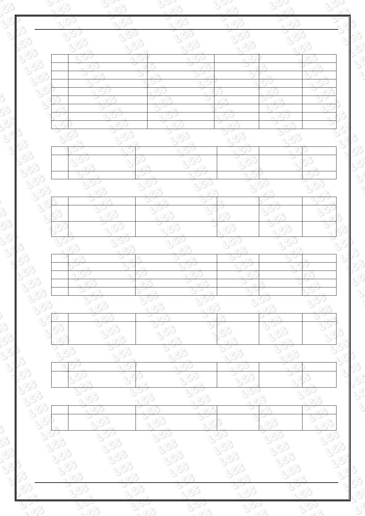
2.4.Measurement Uncertainty
Test Item Frequency Range Expanded
uncertainty (Ulab)
Expanded
uncertainty (Ucispr)
Conducted Emission
(9kHz to 150kHz) 2.63 dB 4.0 dB
(150kHz to 30MHz) 2.35 dB 3.6 dB
Power disturbance (30MHz to 300MHz) 2.90dB 4.5 dB
Electromagnetic
Radiated Emission
(3-loop)
(9kHz to 30MHz) 3.60 dB N/A
Radiated Emission (9kHz to 30MHz) 3.68 dB N/A
Radiated Emission (30MHz to 1000MHz) 3.48 dB 5.2 dB
Radiated Emission (above 1000MHz) 3.90 dB N/A
Mains Harmonic Voltage 0.510% N/A
Voltage Fluctuations
& Flicker Voltage 0.510% N/A
(1)
Where relevant, the following measurement uncertainty levels have been estimated for tests
performed on the apparatus.
(2) The reported expanded uncertainty of measurement is stated as the standard uncertainty of
measurement multiplied by the coverage factor of k=2, which for a normal distribution
corresponds to a coverage probability of approximately 95%.
SHENZHEN LCS COMPLIANCE TESTING LABORATORY LTD. Report No.: LCS1506010003E
This report shall not be reproduced except in full, without the written approval of Shenzhen LCS Compliance Testing Laboratory Ltd.
Page 10 of 29
3. MEASURING DEVICES AND TEST EQUIPMENT
3.1.Conducted Disturbance
Item
Test Equipment Manufacturer Model No. Serial No.
Last Cal.
1 EMI Test Receiver ROHDE & SCHWARZ
ESCI 101142 2014/06/18
2 10dB Attenuator SCHWARZBECK OSPAM236 9729 2014/06/18
3 Artificial Mains ROHDE & SCHWARZ
ENV216 101288 2014/06/18
4 EMI Test Software AUDIX E3 N/A 2014/06/18
3.2.Disturbance Power
Item
Test Equipment Manufacturer Model No. Serial No.
Last Cal.
1 EMI Test Receiver ROHDE & SCHWARZ
ESCI 101142 2014/06/18
2 Absorbing clamp ROHDE & SCHWARZ
MDS 21 4033 2014/08/30
3 EMI Test Software AUDIX E3 N/A 2014/06/18
3.3.Radiated Electromagnetic Disturbance
Item
Test Equipment Manufacturer Model No. Serial No.
Last Cal.
1 EMI Test Receiver ROHDE & SCHWARZ
ESCI 1011423 2014/06/18
2 Triple-loop Antenna EVERFINE LLA-2 11050003 2014/06/18
3 EMI Test Receiver ROHDE & SCHWARZ
ESPI 101840 2014/06/18
4 EMI Test Software AUDIX E3 N/A 2014/06/18
3.4.Radiated Disturbance (Electric Field)
Item
Test Equipment Manufacturer Model No. Serial No.
Last Cal.
1 3m Semi Anechoic Chamber
SIDT FRANKONIA SAC-3M 03CH03-HY
2015/02/04
2 EMI Test Receiver ROHDE & SCHWARZ
ESPI 101840 2014/06/18
3 Log per Antenna SCHWARZBECK VULB9163 9163-470 2014/06/18
4 EMI Test Software AUDIX E3 N/A 2014/06/18
5 Positioning Controller MF MF-7082 / 2014/06/18
3.5.Harmonic Current
Item
Test Equipment Manufacturer Model No. Serial No.
Last Cal.
1 Power Analyzer Test System
Voltech PM6000 20000670053
2014/06/18
3.6.Voltage fluctuation and Flicker
Item
Test Equipment Manufacturer Model No. Serial No.
Last Cal.
1 Power Analyzer Test System
Voltech PM6000 20000670053
2014/06/18
3.7.Electrostatic Discharge
Item
Test Equipment Manufacturer Model No. Serial No. Last Cal.
1 ESD Simulator KIKUSUI KC001311 KES4021 2014/09/02
SHENZHEN LCS COMPLIANCE TESTING LABORATORY LTD. Report No.: LCS1506010003E
This report shall not be reproduced except in full, without the written approval of Shenzhen LCS Compliance Testing Laboratory Ltd.
Page 11 of 29
3.8.RF Field Strength Susceptibility
Item
Test Equipment Manufacturer Model No. Serial No. Last Cal.
1 SIGNAL GENERATOR HP 8648A 625U00573 2014/06/18
2 Amplifier AR 500A100 17034 2014/06/18
3 Amplifier AR 100W/1000M1
17028 2014/06/18
4 Isotropic Field Monitor AR FM2000 16829 2014/06/18
5 Isotropic Field Probe AR FP2000 16755 2014/06/18
6 Bi-conic Antenna EMCO 3108 9507-2534 2014/06/18
7 By-log-periodic Antenna AR AT1080 16812 2014/06/18
8 EMS Test Software ROHDE & SCHWARZ
ESK1 N/A 2014/06/18
3.9.Electrical Fast Transient/Burst
Item
Test Equipment Manufacturer Model No. Serial No. Last Cal.
1 Electrical fast
transient(EFT)generator
3CTEST EFT-4021 EC0461044 2015/01/20
2 Coupling Clamp 3CTEST EFTC EC0441098 2014/06/18
3.10.Surge
Item
Test Equipment Manufacturer Model No. Serial No. Last Cal.
1 Surge test system 3CTEST SG5006G EC5581070 2014/06/18
2 Coupling/decoupling
network 3CTEST SGN-5010G
CS5591033 2014/06/18
3.11.Conducted Susceptibility
Item
Test Equipment Manufacturer Model No. Serial No. Last Cal.
1 Simulator EMTEST CIT-10 A126A1195 2014/06/18
2 CDN EMTEST CDN-M2 A2210177 2014/06/18
3 CDN EMTEST CDN-M3 A2210177 2014/06/18
4 Attenuator EMTEST ATT6 50FP-006-H3B
2014/06/18
3.12.Power Frequency Magnetic Field Susceptibility
Item
Test Equipment Manufacturer Model No. Serial No. Last Cal.
1
Power frequency
mag-field generator
System
EVERFINE EMS61000-8K
906003 2014/06/18
3.13.Voltage Dips
Item
Test Equipment Manufacturer Model No. Serial No. Last Cal.
1 Voltage dips and up
generator 3CTEST VDG-1105G
EC0171014 2014/06/18
3.14.Voltage Short Interruptions
Item
Test Equipment Manufacturer Model No. Serial No. Last Cal.
1 Voltage dips and up
generator 3CTEST VDG-1105G
EC0171014 2014/06/18
SHENZHEN LCS COMPLIANCE TESTING LABORATORY LTD. Report No.: LCS1506010003E
This report shall not be reproduced except in full, without the written approval of Shenzhen LCS Compliance Testing Laboratory Ltd.
Page 12 of 29
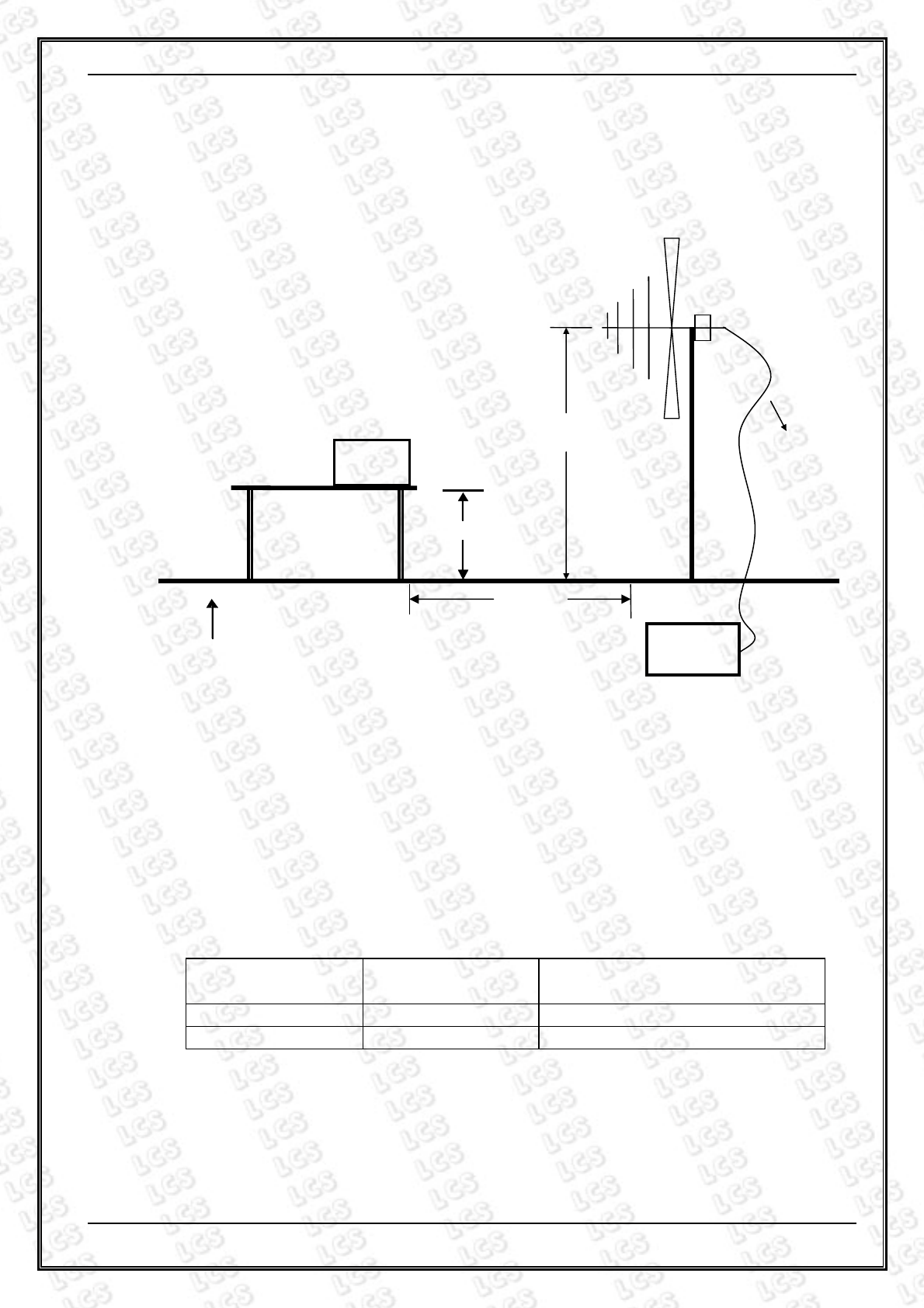
4. RADIATED EMISSION MEASUREMENT
4.1.Block Diagram of Test Setup
4.2.Measuring Standard
EN 55022: 2010
4.3.Radiated Emission Limits
EN 55022 Limits:
All emanations from a class B device or system, including any network of conductors and
apparatus connected thereto, shall not exceed the level of field strengths specified below:
FREQUENCY DISTANCE FIELD STRENGTHS LIMIT
(MHz) (Meters) (dB
µ
V/m)
30 ~ 230 3 40
230 ~ 1000 3 47
Note: (1) The smaller limit shall apply at the combination point between two frequency
bands.
(2) Distance refers to the distance in meters between the measuring instrument
antenna and the closed point of any part of the EUT.
1m ~ 4m
Ground Plane
0.8 m
EUT
EMI
Receiver
Coaxial Cable
3 m

SHENZHEN LCS COMPLIANCE TESTING LABORATORY LTD. Report No.: LCS1506010003E
This report shall not be reproduced except in full, without the written approval of Shenzhen LCS Compliance Testing Laboratory Ltd.
Page 13 of 29
4.4.EUT Configuration on Test
The EN 55022 regulations test method must be used to find the maximum emission
during radiated emission measurement.
4.5.Operating Condition of EUT
4.5.1 Turn on the power.
4.5.2 After that, let the EUT work in test mode (ON) and measure it.
4.6.Test Procedure
The EUT is placed on a turntable, which is 0.8 meter high above the ground. The
turntable can rotate 360 degrees to determine the position of the maximum emission
level. The EUT is set 3 meters away from the receiving antenna, which is mounted on a
antenna tower. The antenna can be moved up and down from 1 to 4 meters to find out
the maximum emission level. By-log antenna is used as a receiving antenna. Both
horizontal and vertical polarization of the antenna is set on test.
The bandwidth of the Receiver is set at 120kHz.
The frequency range from 30MHz to 1000MHz is investigated.
4.7.Test Results
PASS.
The test result please refer to the next page.

SHENZHEN LCS COMPLIANCE TESTING LABORATORY LTD. Report No.: LCS1506010003E
This report shall not be reproduced except in full, without the written approval of Shenzhen LCS Compliance Testing Laboratory Ltd.
Page 14 of 29
Model No. U3H342 Test Mode ON
Environmental Conditions 24℃/ 56% RH Detector Function Quasi-peak
Pol Vertical
Distance
3m
Test Engineer Cherry Chen
Model No. U3H342 Test Mode ON
Environmental Conditions 24℃/ 56% RH Detector Function Quasi-peak
Pol
Horizontal
Distance
3m
Test Engineer
Cherry Chen
SHENZHEN LCS COMPLIANCE TESTING LABORATORY LTD. Report No.: LCS1506010003E
This report shall not be reproduced except in full, without the written approval of Shenzhen LCS Compliance Testing Laboratory Ltd.
Page 15 of 29
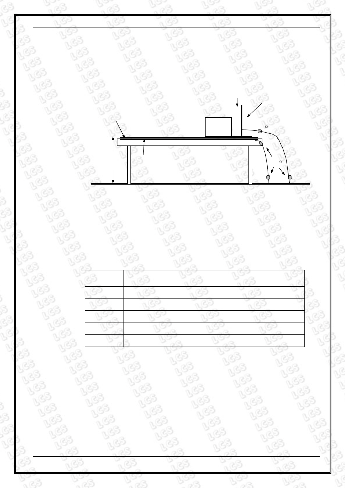
5. ELECTROSTATIC DISCHARGE IMMUNITY TEST
5.1.Block Diagram of Test Setup
5.2.Test Standard
EN 55024: 2010
Severity Level: 3 / Air Discharge: ±8KV, Level: 2 / Contact Discharge: ±4KV)
5.3.Severity Levels and Performance Criterion
5.3.1.Severity level
Level Test Voltage
Contact Discharge (KV)
Test Voltage
Air Discharge (KV)
1. ±2 ±2
2. ±4 ±4
3. ±6 ±8
4. ±8 ±15
X Special Special
5.3.2.Performance Criterion: B
5.4.EUT Configuration on Test
The configuration of EUT is listed in Section 2.1.
5.5.Operating Condition of EUT
Same as conducted emission measurement, which is listed in Section 4.5, Except the
test set up replaced by Section 5.1.
470 k
VCP
10 cm
EUT
HCP
0.5 mm Thick
Insulator
Ground
470 k
0.8 m

SHENZHEN LCS COMPLIANCE TESTING LABORATORY LTD. Report No.: LCS1506010003E
This report shall not be reproduced except in full, without the written approval of Shenzhen LCS Compliance Testing Laboratory Ltd.
Page 16 of 29
5.6.Test Procedure
5.6.1.Air Discharge
This test is done on a non-conductive surface. The round discharge tip of the discharge
electrode shall be approached as fast as possible to touch the EUT.
After each discharge, the discharge electrode shall be removed from the EUT.
The generator is then re-triggered for a new single discharge and repeated 10
times for each pre-selected test point. This procedure shall be repeated until all
the air discharge completed
5.6.2.Contact Discharge
All the procedure shall be same as Section 5.6.1. Except that the tip of the discharge
electrode shall touch the EUT before the discharge switch is operated.
5.6.3.Indirect Discharge For Horizontal Coupling Plane
At least 10 single discharges (in the most sensitive polarity) shall be applied at the front
edge of each HCP opposite the center point of each unit (if applicable) of the EUT and
0.1m from the front of the EUT. The long axis of the discharge electrode shall be in the
plane of the HCP and perpendicular to its front edge during the discharge.
5.6.4.Indirect Discharge For Vertical Coupling Plane
At least 10 single discharge (in the most sensitive polarity) shall be applied to the center
of one vertical edge of the coupling plane. The coupling plane, of dimensions 0.5m X
0.5m, is placed parallel to, and positioned at a distance of 0.1m from the EUT.
Discharges shall be applied to the coupling plane, with this plane in sufficient different
positions that the four faces of the EUT are completely illuminated.
5.7.Test Results
PASS.
Please refer to the following pages
SHENZHEN LCS COMPLIANCE TESTING LABORATORY LTD. Report No.: LCS1506010003E
This report shall not be reproduced except in full, without the written approval of Shenzhen LCS Compliance Testing Laboratory Ltd.
Page 17 of 29
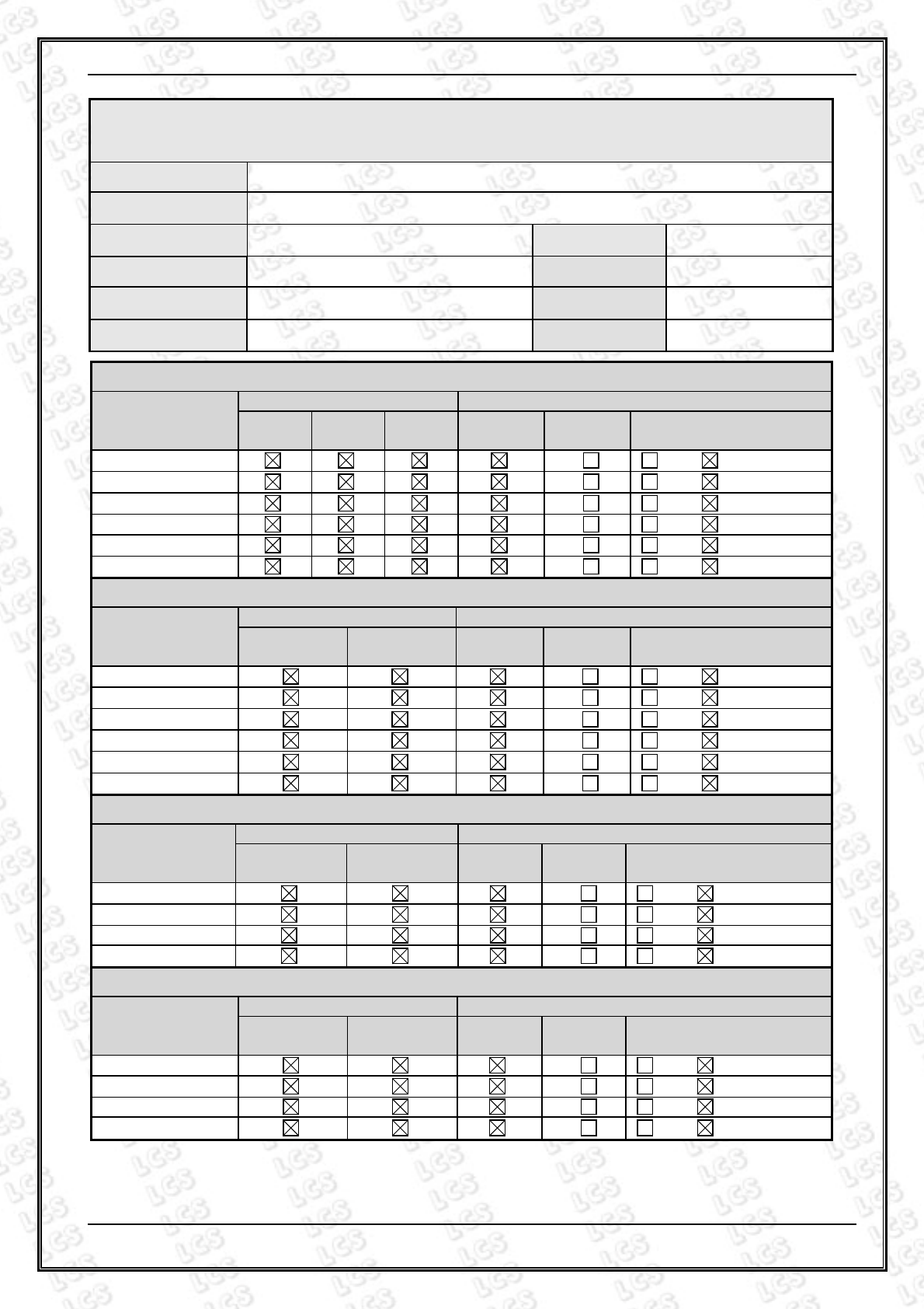
Electrostatic Discharger Test Results
Standard IEC 61000-4-2 EN 61000-4-2
Applicant Magicview Technology Co., Ltd.
EUT USB HUBUSB HUB Temperature 24℃
M/N U3H342 Humidity 53%
Criterion B Pressure 1021mbar
Test Mode ON Test Engineer
Cherry Chen
Air Discharge
Test Points
Test Levels Results
± 2kV ± 4kV ± 8kV Passed Fail
Performance
Criterion
Front A B
Back A B
Left A B
Right A B
Top A B
Bottom
A B
Contact Discharge
Test Points
Test Levels Results
± 2 kV ±4 kV Passed Fail Performance
Criterion
Front A B
Back A B
Left A B
Right A B
Top A B
Bottom A B
Discharge To Horizontal Coupling Plane
Side of EUT
Test Levels Results
± 2 kV ± 4 kV Passed Fail Performance
Criterion
Front A B
Back A B
Left A B
Right A B
Discharge To Vertical Coupling Plane
Side of EUT
Test Levels Results
± 2 kV ± 4 kV Passed Fail Performance
Criterion
Front A B
Back A B
Left A B
Right A B
SHENZHEN LCS COMPLIANCE TESTING LABORATORY LTD. Report No.: LCS1506010003E
This report shall not be reproduced except in full, without the written approval of Shenzhen LCS Compliance Testing Laboratory Ltd.
Page 18 of 29
6.
RF FIELD STRENGTH SUSCEPTIBILITY TEST
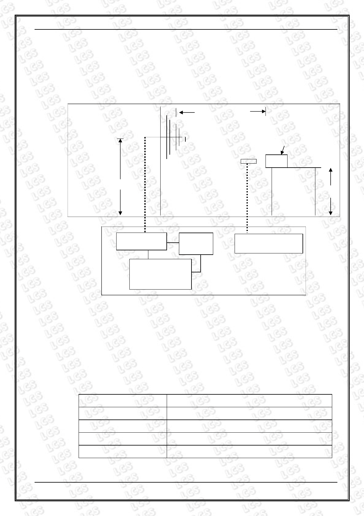
6.1.Block Diagram of Test
6.2.Test Standard
EN 55024: 2010
(EN 61000-4-3: 2006+A1: 2008 Severity Level: 2, 3V / m)
6.3.Severity Levels and Performance Criterion
6.3.1.Severity Levels
6.3.2.Performance Criterion: A
Level Field Strength (V/m)
1. 1
2. 3
3. 10
X. Special
0.8m
Power Amp
Signal
Generator
EUT Monitoring by
using a camera
Control Room
9
x
6
x
6
EUT & Support
Units
PC Controller to
control S.G. & PA as
well as forward
power
3 meter
1.5 meter
SHENZHEN LCS COMPLIANCE TESTING LABORATORY LTD. Report No.: LCS1506010003E
This report shall not be reproduced except in full, without the written approval of Shenzhen LCS Compliance Testing Laboratory Ltd.
Page 19 of 29
6.4.EUT Configuration on Test
The configuration of the EUT is same as Section 2.1.
6.5.Operating Condition of EUT
Same as radiated emission measurement, which is listed in Section 4.5, except the test
setup replaced as Section 6.1.
6.6.Test Procedure
The EUT are placed on a table, which is 0.8 meter high above the ground. The EUT is set
3 meters away from the transmitting antenna, which is mounted on an antenna tower.
Both horizontal and vertical polarization of the antenna is set on test. Each of the four
sides of the EUT must be faced this transmitting antenna and measured individually.
In order to judge the EUT performance, a CCD Recording is used to monitor its screen.
All the scanning conditions are as following:
Condition of Test Remark
---------------------------------------------- ---------------------------------------
1. Fielded Strength
2. Radiated Signal
3. Scanning Frequency
4. Sweep time of radiated
5. Dwell Time
3V/m (Severity Level 2)
Unmodulated
80-1000MHz
0.0015 Decade/s
3 Sec.
6.7.Test Results
PASS.
Please refer to the following page.
SHENZHEN LCS COMPLIANCE TESTING LABORATORY LTD. Report No.: LCS1506010003E
This report shall not be reproduced except in full, without the written approval of Shenzhen LCS Compliance Testing Laboratory Ltd.
Page 20 of 29
RF Field Strength Susceptibility Test Results
Standard IEC 61000-4-3 EN 61000-4-3
Applicant Magicview Technology Co., Ltd.
EUT USB HUB Temperature
24℃
M/N U3H342 Humidity
53%
Field Strength 3 V/m Criterion
A
Test Mode ON
Test Engineer
Cherry Chen
Frequency Range
80 MHz to 1000 MHz
Modulation
None Pulse AM 1KHz 80%
Steps
1%
Horizontal Vertical
Front PASS PASS
Right PASS PASS
Rear PASS PASS
Left PASS PASS
Test Equipment:
1. Signal Generator: 2031 (MARCONI)
2. Power Amplifier: 500A100 & 100W/1000M1 (A&R)
3. Power Antenna: 3108 (EMCO) & AT1080 (A&R)
4. Field Monitor: FM2000 (A&R)
Note:

SHENZHEN LCS COMPLIANCE TESTING LABORATORY LTD. Report No.: LCS1506010003E
This report shall not be reproduced except in full, without the written approval of Shenzhen LCS Compliance Testing Laboratory Ltd.
Page 21 of 29
7. MAGNETIC FIELD SUSCEPTIBILITY TEST
7.1.Block Diagram of Test Setup
7.2.Test Standard
EN 55024: 2010
(EN 61000-4-8: 2010, Severity Level: Level 1, 1A / m)
7.3.Severity Levels and Performance Criterion
7.3.1.Severity Levels
Level Field Strength (A/m)
1 1
2 3
3 10
4 30
5 100
X Special
7.3.2.Performance Criterion: A
7.4.EUT Configuration on Test
The configuration of the EUT is same as Section 2.1.
EUT
Induction Coil
Signal
Generator
Ground

SHENZHEN LCS COMPLIANCE TESTING LABORATORY LTD. Report No.: LCS1506010003E
This report shall not be reproduced except in full, without the written approval of Shenzhen LCS Compliance Testing Laboratory Ltd.
Page 22 of 29
7.5.Test Procedure
The EUT is placed in the middle of a induction coil (1*1m), under which is a 1*1*0.1m
(high) table, this small table is also placed on a larger table, 0.8 m above the ground.
Both horizontal and vertical polarization of the induction coil is set on test, so that each
side of the EUT is affected by the magnetic field. Also can reach the same aim by
change the position of the EUT.
7.6.Test Results
PASS.
Please refer to the following page.
SHENZHEN LCS COMPLIANCE TESTING LABORATORY LTD. Report No.: LCS1506010003E
This report shall not be reproduced except in full, without the written approval of Shenzhen LCS Compliance Testing Laboratory Ltd.
Page 23 of 29
Magnetic Field Immunity Test Result
Standard IEC 61000-4-8 EN 61000-4-8
Applicant Magicview Technology Co., Ltd.
EUT USB HUB Temperature
24℃
M/N U3H342 Humidity 53%
Test Mode ON Criterion A
Test Engineer Cherry Chen
Test Level
(A/M)
Testing
Duration Coil Orientation Criterion Result
1 5 mins X A PASS
1 5 mins Y A PASS
1 5 mins Z A PASS
Note:

SHENZHEN LCS COMPLIANCE TESTING LABORATORY LTD. Report No.: LCS1506010003E
This report shall not be reproduced except in full, without the written approval of Shenzhen LCS Compliance Testing Laboratory Ltd.
Page 24 of 29
8. PHOTOGRAPH
8.1.Photo of Radiated Measurement
8.2.Photo of Electrostatic Discharge Test

SHENZHEN LCS COMPLIANCE TESTING LABORATORY LTD. Report No.: LCS1506010003E
This report shall not be reproduced except in full, without the written approval of Shenzhen LCS Compliance Testing Laboratory Ltd.
Page 25 of 29
8.3.Photo of Magnetic Field Immunity Test

SHENZHEN LCS COMPLIANCE TESTING LABORATORY LTD. Report No.: LCS1506010003E
This report shall not be reproduced except in full, without the written approval of Shenzhen LCS Compliance Testing Laboratory Ltd.
Page 26 of 29
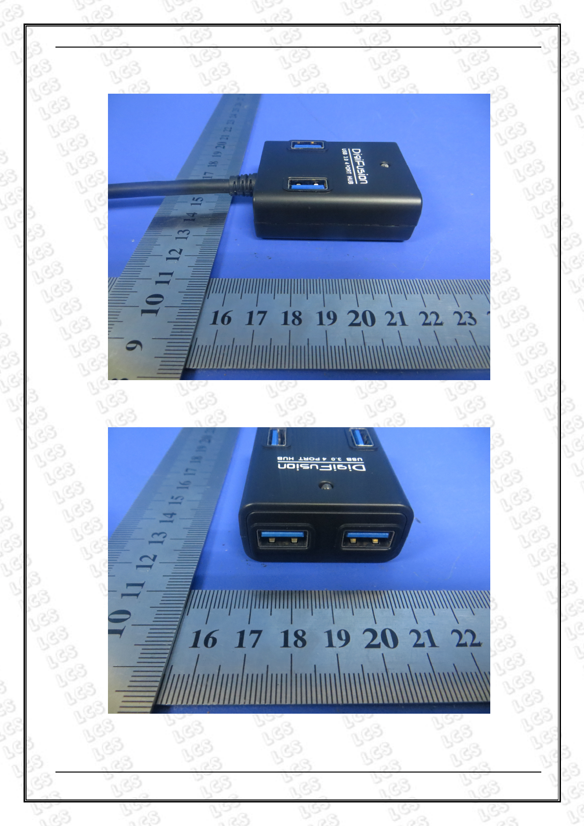
9. EXTERNAL AND INTERNAL PHOTOS OF THE EUT
Fig 1
Fig 2
SHENZHEN LCS COMPLIANCE TESTING LABORATORY LTD. Report No.: LCS1506010003E
This report shall not be reproduced except in full, without the written approval of Shenzhen LCS Compliance Testing Laboratory Ltd.
Page 27 of 29
Fig 3
Fig 4

SHENZHEN LCS COMPLIANCE TESTING LABORATORY LTD. Report No.: LCS1506010003E
This report shall not be reproduced except in full, without the written approval of Shenzhen LCS Compliance Testing Laboratory Ltd.
Page 28 of 29
Fig 5
Fig 6

SHENZHEN LCS COMPLIANCE TESTING LABORATORY LTD. Report No.: LCS1506010003E
This report shall not be reproduced except in full, without the written approval of Shenzhen LCS Compliance Testing Laboratory Ltd.
Page 29 of 29
Fig 7
Fig 8
-----------------THE END OF REPORT----------------
