EN 300440
2016-04-12
: Pdf En 300440 EN_300440 CertsReports 525824 ProductFiles
Open the PDF directly: View PDF ![]() .
.
Page Count: 31
Shenzhen SEM.Test Technology Co., Ltd.
REPORT NO.: STR15098069E-2 PAGE 1 OF 31 RF REPORT
Radio
Measurement and Test Report
For
Winstars Technology Limited
Block 4, TaiSong Industrial Park, DaLang Street, LongHua Town, Bao’an
district, Shenzhen, China
Test Standards:
EN 300 440-1 V1.6.1 (2010-08)
EN 300 440-2 V1.4.1 (2010-08)
Product Description: High Power Wi-fi AP/Router
Tested Model: WS-WN570HA1
Report No.: STR15098069E-2
Tested Date: 2015-09-08 to 2015-09-22
Issued Date: 2015-09-22
Tested By: Jack Kang / Engineer
Reviewed By: Silin Chen / Engineer
Approved & Authorized By: Jandy So / PSQ Manager
Prepared By:
Shenzhen SEM.Test Technology Co., Ltd.
1/F, Building A, Hongwei Industrial Park, Liuxian 2nd Road,
Bao'an District, Shenzhen, P.R.C.(518101)
Tel.: +86-755-33663308 Fax.: +86-755-33663309 Website: www.semtest.com.cn
Note: This test report is limited to the above client company and the product model only. It
may not be duplicated without prior permitted by Shenzhen SEM.Test Technology Co., Ltd.
SEM.Test

Shenzhen SEM.Test Technology Co., Ltd.
REPORT NO.: STR15098069E-2 PAGE 2 OF 31 RF REPORT
TABLE OF CONTENTS
1 GENERAL INFORMATION ..................................................................................................................................... 3
1.1 Product Description for Equipment Under Test (EUT) .................................................................................... 3
1.2 Test Standards ................................................................................................................................................... 4
1.3 Test Methodology ............................................................................................................................................. 4
1.4 Test Facility ....................................................................................................................................................... 4
1.5 EUT Setup and Test Mode ................................................................................................................................ 5
1.6 Measurement Uncertainty ................................................................................................................................. 5
1.7 Test Equipment List and Details ....................................................................................................................... 6
2. SUMMARY OF TEST RESULTS ............................................................................................................................. 7
3. EQUIVALENT ISOTROPICALLY RADIATED POWER ..................................................................................................... 8
3.1 Standard Applicable .......................................................................................................................................... 8
3.2 Test Procedure ................................................................................................................................................... 8
3.3 Summary of Test Results .................................................................................................................................. 9
4. PERMITTED RANGE OF OPERATING FREQUENCIES .................................................................................................. 10
4.1 Applicable Standard ........................................................................................................................................ 10
4.2 Test Procedure ................................................................................................................................................. 10
4.3 Test Results/Plots ............................................................................................................................................ 11
5. SPURIOUS EMISSIONS ................................................................................................................................................. 13
5.1 Limit of Spurious Emissions ........................................................................................................................... 13
5.2 Test Procedure ................................................................................................................................................. 13
5.3 Environmental Conditions .............................................................................................................................. 13
5.4 Summary of Test Results/Plots ....................................................................................................................... 13
6. DUTY CYCLE .............................................................................................................................................................. 21
6.1 Applicable Standard ........................................................................................................................................ 21
6.2 Test Procedure ................................................................................................................................................. 21
6.3 Environmental Conditions .............................................................................................................................. 21
6.4 Summary of Test Results/Plots ....................................................................................................................... 21
7. RECEIVER SPURIOUS EMISSIONS ............................................................................................................................... 22
7.1 Limit of Spurious Emissions ........................................................................................................................... 22
7.2 Test Procedure ................................................................................................................................................. 22
7.3 Environmental Conditions .............................................................................................................................. 22
7.4 Summary of Test Results/Plots ....................................................................................................................... 22
EXHIBIT 1 - PRODUCT LABELING ........................................................................................................................ 25
Proposed CE Label Format ................................................................................................................................... 25
Proposed Label Location on EUT ......................................................................................................................... 25
EXHIBIT 2 - EUT PHOTOGRAPHS .......................................................................................................................... 26
EXHIBIT 3 - TEST SETUP PHOTOGRAPHS .......................................................................................................... 30
SEM.Test
Shenzhen SEM.Test Technology Co., Ltd.
REPORT NO.: STR15098069E-2 PAGE 3 OF 31 RF REPORT
1 GENERAL INFORMATION
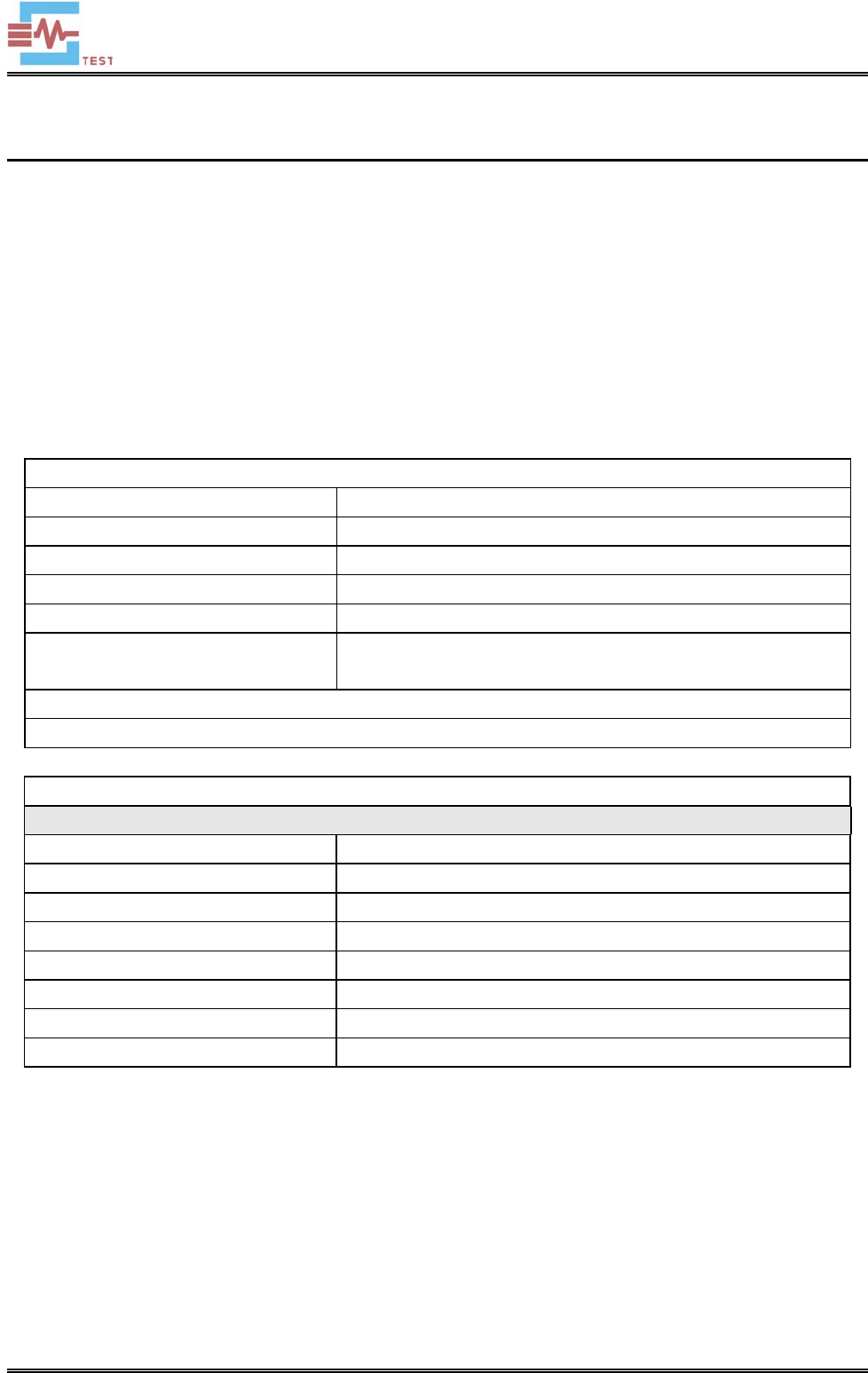
1.1 Product Description for Equipment Under Test (EUT)
Client Information
Applicant: Winstars Technology Limited
Address of applicant: Block 4, TaiSong Industrial Park, DaLang Street, LongHua
Town, Bao’an district, Shenzhen, China
Manufacturer: Winstars Technology Limited
Address of manufacturer: Block 4, TaiSong Industrial Park, DaLang Street, LongHua
Town, Bao’an district, Shenzhen, China
General Description of EUT
Product Name: High Power Wi-fi AP/Router
Trade Name: N/A
Model No.: WS-WN570HA1
Adding Model(s): 525824
Rated Voltage: DC 24V from adapter
Power Adaptor Model: Model: TDX-2400500
Input: AC 100-240V 50/60Hz, Output: DC 24V 0.5A
Note: The test data is gathered from a production sample, provided by the manufacturer.
Technical Characteristics of EUT
Wi-Fi(5.8G)
Support Standards: 802.11ac
Frequency Range: 5775-5825MHz for 802.11a
RF Output Power: 13.52dBm (EIRP)
Type of Modulation: BPSK/QPSK/16QAM/64QAM/256QAM
Quantity of Channels 6 for 802.11ac
Channel Separation: 10MHz
Type of Antenna: External Antenna
Antenna Gain: 7.0dBi
SEM.Test

Shenzhen SEM.Test Technology Co., Ltd.
REPORT NO.: STR15098069E-2 PAGE 4 OF 31 RF REPORT
1.2 Test Standards
The following report is prepared on behalf of the Winstars Technology Limited in accordance with ETSI EN 300
440-2, Electromagnetic compatibility and Radio spectrum Matters (ERM); Short range devices; Radio equipment
to be used in the 1 GHz to 40 GHz frequency range; Part 2: Harmonized EN under article 3.2 of the R&TTE
Directive.
The objective of the manufacturer is to determine compliance with ETSI EN 300 440-2, Electromagnetic
compatibility and Radio spectrum Matters (ERM); Short range devices; Radio equipment to be used in the 1 GHz
to 40 GHz frequency range; Part 2: Harmonized EN under article 3.2 of the R&TTE Directive.
Maintenance of compliance is the responsibility of the manufacturer. Any modification of the product maybe
which result in lowering the immunity should be checked to ensure compliance has been maintained
1.3 Test Methodology
All measurements contained in this report were conducted with ETSI EN 300 440-1, Electromagnetic
compatibility and Radio spectrum Matters (ERM); Short Range Devices (SRD); Radio equipment to be used in
the 1 GHz to 40 GHz frequency range; Part 1: Technical characteristics and test methods.
The equipment under test (EUT) was configured to measure its highest possible emission level. For more detail
refer to the Operating Instructions.
1.4 Test Facility
FCC – Registration No.: 934118
Shenzhen SEM.Test Technology Co., Ltd. EMC Laboratory has been registered and fully described in a report
filed with the (FCC) Federal Communications Commission. The acceptance letter from the FCC is maintained in
our files and the Registration is 934118.
Industry Canada (IC) Registration No.: 11464A
The 3m Semi-anechoic chamber of Shenzhen SEM.Test Technology Co., Ltd. has been registered by Certification
and Engineering Bureau of Industry Canada for radio equipment testing with Registration No.: 11464A.
CNAS Registration No.: L4062
Shenzhen SEM.Test Technology Co., Ltd. is a testing organization accredited by China National Accreditation
Service for Conformity Assessment (CNAS) according to ISO/IEC 17025. The accreditation certificate number is
L4062. All measurement facilities used to collect the measurement data are located at 1/F, Building A, Hongwei
Industrial Park, Liuxian 2nd Road, Bao’an District, Shenzhen, P.R.C (518101).
SEM.Test
Shenzhen SEM.Test Technology Co., Ltd.
REPORT NO.: STR15098069E-2 PAGE 5 OF 31 RF REPORT
1.5 EUT Setup and Test Mode
The equipment under test (EUT) was configured to measure its highest possible emission/immunity level. The test
modes were adapted according to the operation manual for use, the EUT was operated in the engineering mode to
fix the Tx frequency that was for the purpose of the measurements, more detailed description as follows:
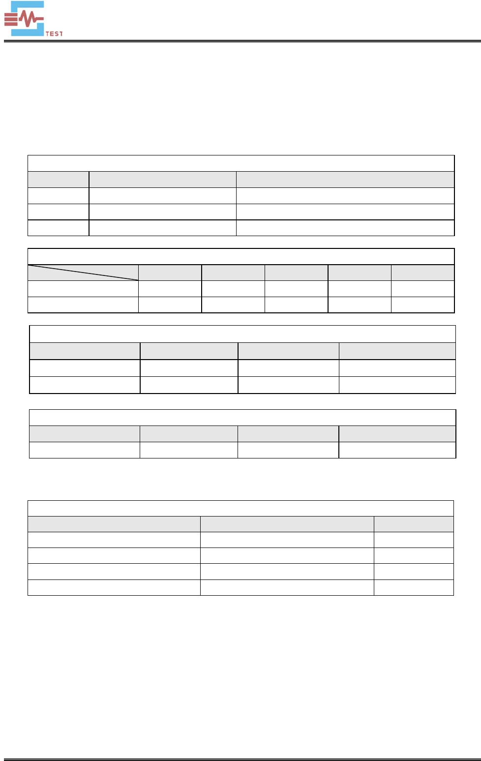
Test Mode List
Test Mode Description Remark
TM1 Low Channel 5775 MHz
TM2 Middle Channel 5805 MHz
TM3 High Channel 5825 MHz
Test Conditions
Normal LTLV LTHV HTHV HTLV
Temperature (℃) 20 -20 -20 55 55
Voltage (V) AC 230V AC 207V AC 253V AC 207V AC 253V
Special Cable List and Details
Cable Description Length (m) Shielded/Unshielded With / Without Ferrite
DC Cable 1.0 Unshielded Without Ferrite
RJ45 Cable 1.0 Unshielded Without Ferrite
Auxiliary Equipment List and Details
Description Manufacturer Model Serial Number
Notebook Lenovo E10 LR-63C8R
1.6 Measurement Uncertainty
Measurement uncertainty
Parameter Conditions Uncertainty
EIRP Conducted ±0.42dB
Frequency Range --- ±1×10⁻⁷
Transmitter Spurious Emissions Radiated ±5.2dB
Receiver Spurious Emissions Radiated ±5.2dB
SEM.Test
Shenzhen SEM.Test Technology Co., Ltd.
REPORT NO.: STR15098069E-2 PAGE 6 OF 31 RF REPORT
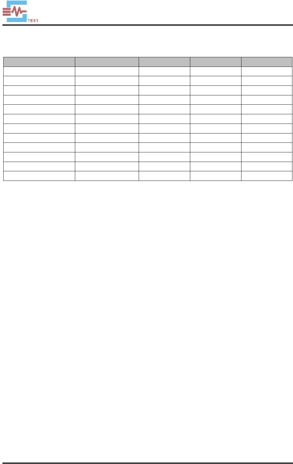
1.7 Test Equipment List and Details
Description Manufacturer Model Serial Number Due. Date
Spectrum Analyzer Agilent E4407B MY41440400 2016-06-16
Spectrum Analyzer Agilent N9020A US47140102 2016-06-16
Signal Generator Agilent 83752A 3610A01453 2016-06-16
Power Divider Weinschel 1506A PM204 2016-06-16
Spectrum Analyzer Rohde & Schwarz FSP 836079/035 2016-06-16
EMI Test Receiver Rohde & Schwarz ESVB 825471/005 2016-06-16
Amplifier Agilent 8447F 3113A06717 2016-06-16
Amplifier C&D PAP-1G18 2002 2016-06-16
Broadband Antenna Schwarz beck VULB9163 9163-333 2016-06-16
Horn Antenna ETS 3117 00086197 2016-06-16
DC Power Supply LW APR-3003 N/A 2016-06-16
Attenuator ATTEN ATS100-4-20
/ 2016-06-16
SEM.Test

Shenzhen SEM.Test Technology Co., Ltd.
REPORT NO.: STR15098069E-2 PAGE 7 OF 31 RF REPORT
2. SUMMARY OF TEST RESULTS
Standards Reference Description of Test Item Result
EN 300440-1
V1.6.1 (2010-08)
7.1.3 Equivalent Isotropically Radiated Power Pass
7.2.4 Permitted Range of Operating Frequencies Pass
7.3.6 Spurious Emissions Pass
7.4.3 Duty Cycle Pass
7.5.1 Additional requirements for FHSS equipment N/A
8.3.5 Receiver Spurious Radiations Pass
Pass: The EUT complies with the essential requirements in the standard
Fail: The EUT does not comply with the essential requirements in the standard
N/A: not applicable
SEM.Test
Shenzhen SEM.Test Technology Co., Ltd.
REPORT NO.: STR15098069E-2 PAGE 8 OF 31 RF REPORT
3. Equivalent Isotropically Radiated Power
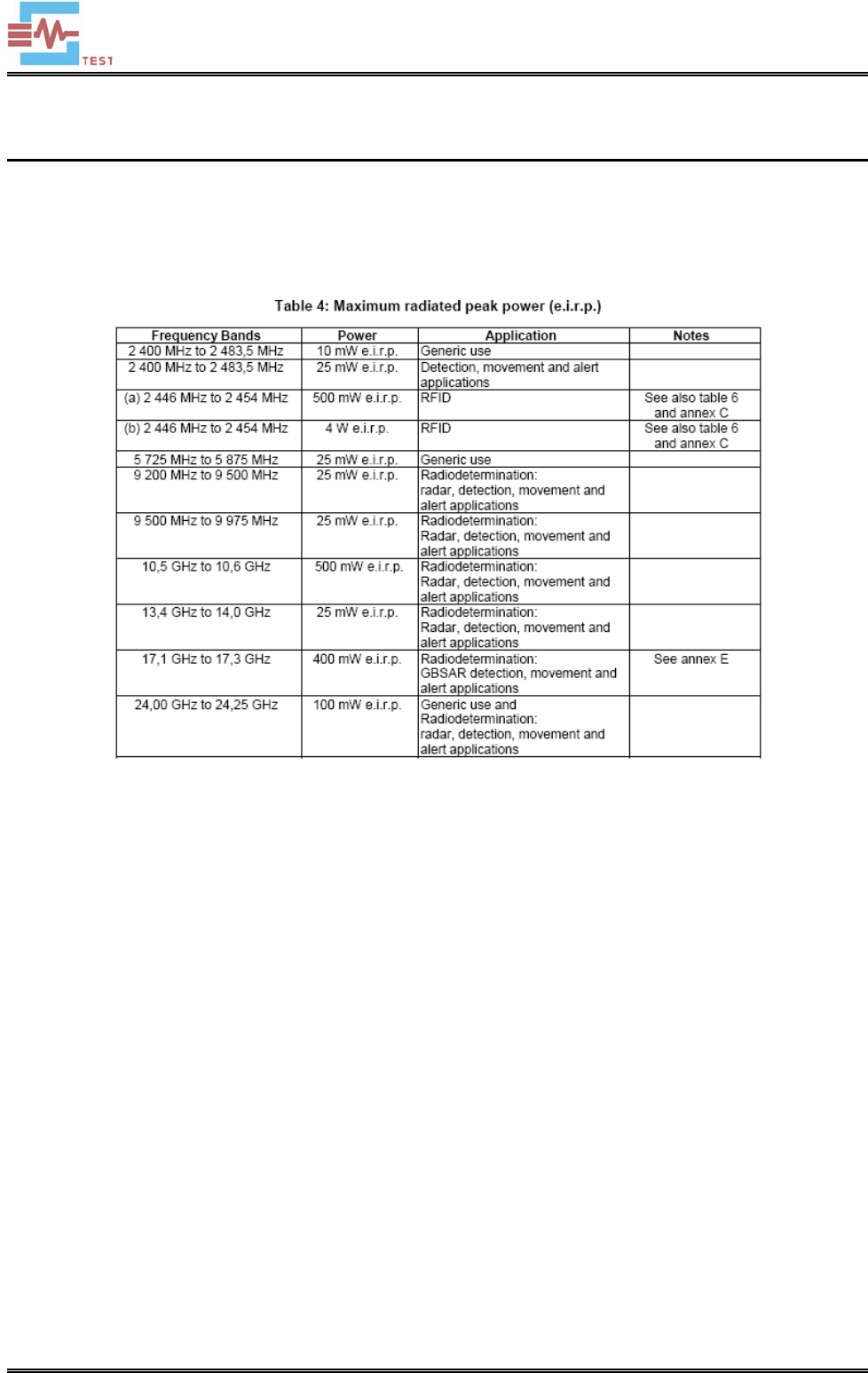
3.1 Standard Applicable
According to ETSI EN 300 440-1 section 7.1.3, the effective radiated power shall not exceed the power class
value given in following table:
3.2 Test Procedure
According to section 7.1.2 of the standard EN 300440-1, the test procedure shall be as follows:
1. Using a suitable means, the output of the transmitter shall be connected to the spectrum analyzer, the spectrum
analyzer shall be capable of faithfully reproducing the envelope peaks and the duty cycle of the transmitter output
signal. The observed duty cycle of the transmitter (Tx on/(Tx on + Tx off)) shall be noted as x, (0 < x < 1) and
recorded.
2. The average output power of the transmitter shall be determined using the spectrum analyzer. The observed
value shall be recorded as "A" (in dBm).
3. The e.i.r.p. shall be calculated from the above measured power output A, the observed duty cycle x, and the
applicable antenna assembly gain "G" in dBi, according to the formula:
- P = A + G + 10 log (1/x);
4. The measurement shall be repeated at the lowest, the middle, and the highest frequency of the stated frequency
range.These frequencies shall be recorded. FHSS equipment shall be made to hop continuously to each of these
three frequencies separately. These measurements shall be performed at normal and extreme test conditions.
SEM.Test
Shenzhen SEM.Test Technology Co., Ltd.
REPORT NO.: STR15098069E-2 PAGE 9 OF 31 RF REPORT
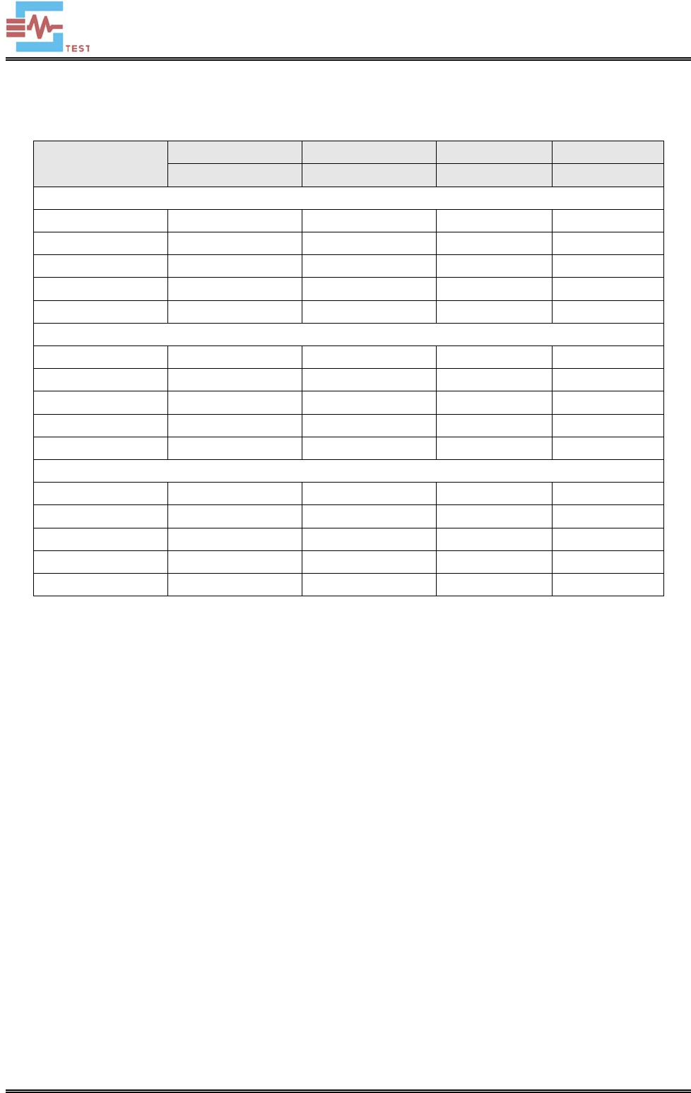
3.3 Summary of Test Results
Test Conditions Measured Value Antenna Gain EIRP Limit
dBm dBi dBm dBm
Low Channel (5775MHz)
Normal 6.52 7 13.52 13.98
LTLV 6.42 7 13.42 13.98
LTHV 6.30 7 13.30 13.98
HTHV 6.09 7 13.09 13.98
HTLV 6.28 7 13.28 13.98
Middle Channel (5805MHz)
Normal 5.89 7 12.89 13.98
LTLV 5.85 7 12.85 13.98
LTHV 5.79 7 12.79 13.98
HTHV 5.69 7 12.69 13.98
HTLV 5.76 7 12.76 13.98
High Channel (5825MHz)
Normal 5.62 7 12.62 13.98
LTLV 5.56 7 12.56 13.98
LTHV 5.59 7 12.59 13.98
HTHV 5.61 7 12.61 13.98
HTLV 5.46 7 12.46 13.98
SEM.Test

Shenzhen SEM.Test Technology Co., Ltd.
REPORT NO.: STR15098069E-2 PAGE 10 OF 31 RF REPORT
4. Permitted Range of Operating Frequencies
4.1 Applicable Standard
According to EN 300 440-1 section 7.2
The frequency range of the equipment is determined by the lowest and highest frequencies occupied by the power
envelope in accordance with CEPT/ERC Recommendation 74-01 [2].
fH is the highest frequency of the power envelope, it is the frequency furthest above the frequency of maximum
power
where the output power drops below the level of –75 dBm/Hz spectral power density (-30 dBm if measured in a
30 kHz reference bandwidth) eirp.
fL is the lowest frequency of the power envelope; it is the frequency furthest below the frequency of maximum
power
where the output power drops below the level of –75 dBm/Hz spectral power density (-30 dBm if measured in a
30 kHz reference bandwidth) eirp.
4.2 Test Procedure
According to section 7.2.2 of the standard EN 300440-1, the test procedure shall be as follows:
1. Put the spectrum analyzer in video averaging mode with a minimum of 50 sweeps selected.
2. Select the lowest operating frequency of the equipment under test and activate the transmitter with modulation
applied. The RF emission of the equipment shall be displayed on the spectrum analyzer.
3. Using the marker of the spectrum analyzer, find lowest frequency below the operating frequency at which
spectral power density drops below the required value.
4. Select the highest operating frequency of the equipment under test and find the highest frequency at which the
spectral power density drop below the required value.
5. The difference between the frequencies measured in step 3 and step 4 is the operating frequency range.
The equivalent isotropically radiated power is then calculated from the measured value, the known antenna gain,
relative to an isotropic antenna, and if applicable, any losses due to cables and connectors in the measurement
system.
SEM.Test

Shenzhen SEM.Test Technology Co., Ltd.
REPORT NO.: STR15098069E-2 PAGE 11 OF 31 RF REPORT
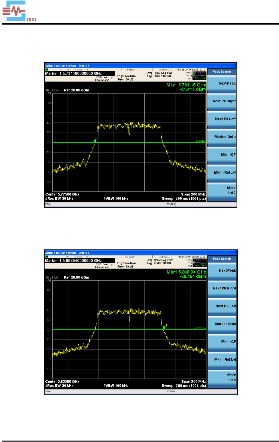
4.3 Test Results/Plots
Test Conditions Frequencies (MHz) at -30dBm/30kHz (EIRP)
Lowest Frequency (fL) Highest Frequency (fH)
Normal 5731.16 5868.94
LTLV 5731.24 5868.86
LTHV 5731.24 5868.86
HTHV 5731.16 5868.94
HTLV 5731.16 5868.94
The frequency range lies within the band 5725MHz to 5875MHz (fL > 5725MHz and fH < 5875MHz),
fullfit the requirements of the standard.
Test plots hereby for reference with the normal case:
SEM.Test
Shenzhen SEM.Test Technology Co., Ltd.
REPORT NO.: STR15098069E-2 PAGE 12 OF 31 RF REPORT
Lowest Frequency Channel Edge for reference:
Highest Frequency Channel Edge for reference:
SEM.Test

Shenzhen SEM.Test Technology Co., Ltd.
REPORT NO.: STR15098069E-2 PAGE 13 OF 31 RF REPORT
5. Spurious Emissions
5.1 Limit of Spurious Emissions
The power of any spurious emission shall not exceed the following values given in the following table.
5.2 Test Procedure
The EUT was placed on a nonmetal table which is 1.5 meter above the grounded reference plane and set to work
in normal operation mode. Details refer to EN 300 440-1 subclause 7.3.4.
The EUT was operating at transmitting mode to represent worst case during final qualification test.
5.3 Environmental Conditions
Temperature: 23 °C
Relative Humidity: 45%
ATM Pressure: 1014 mbar
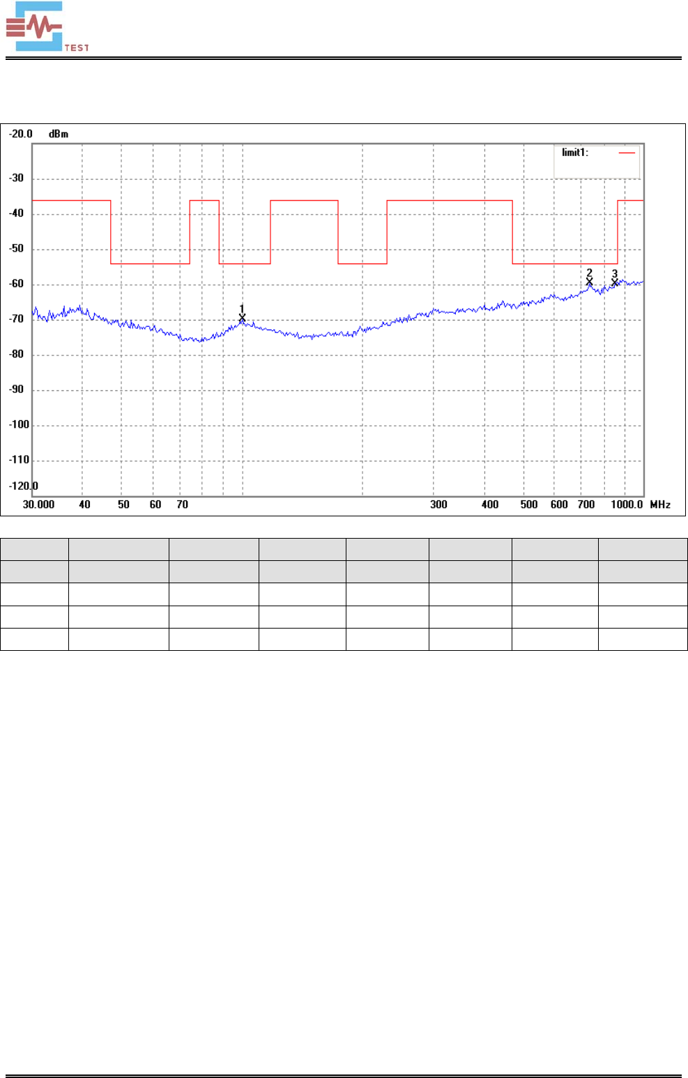
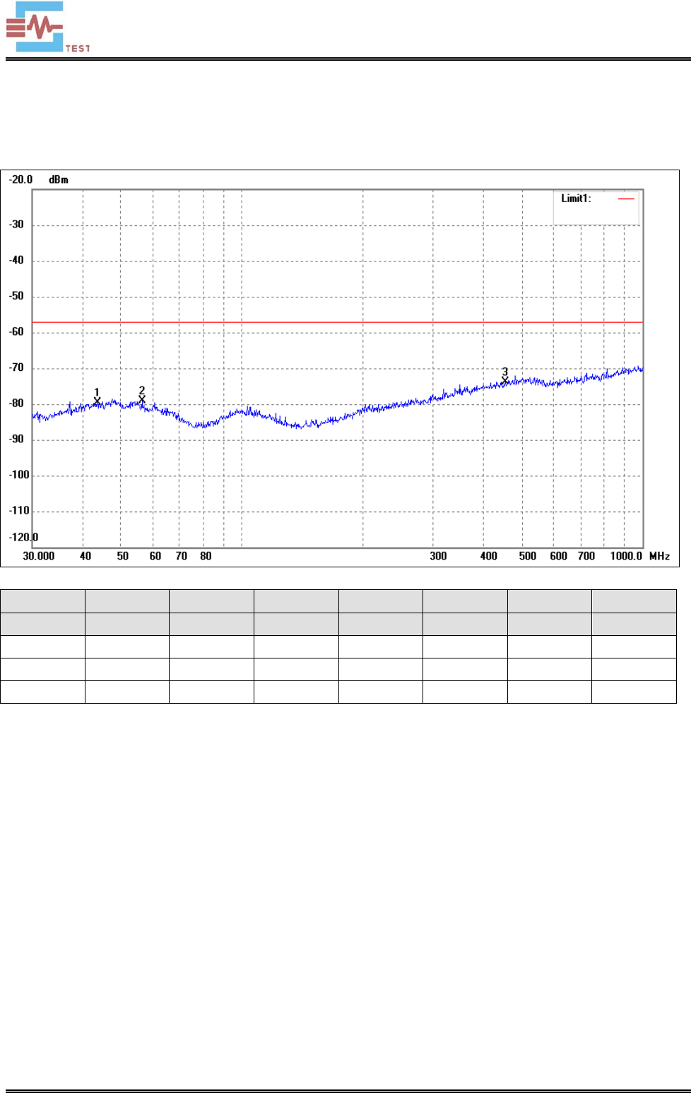
5.4 Summary of Test Results/Plots
According to the data sheet, the EUT complied with the EN 300 440 standards, and had the worst margin of:
-5.41 dB at 851.0353 MHz in the Horizontal polarization, High Channel, 3Meters
SEM.Test
Shenzhen SEM.Test Technology Co., Ltd.
REPORT NO.: STR15098069E-2 PAGE 14 OF 31 RF REPORT
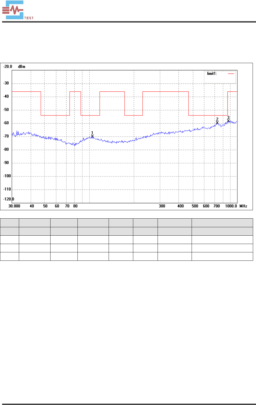
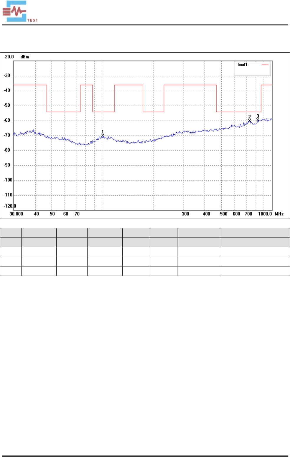
Spurious Emission from 30MHz to 1GHz
Test Mode: Transmitting-Low channel (5775MHz)
Horizontal:
No. Frequency Reading Correct Result Limit Margin Remark
(MHz) (dBm) Factor(dB) (dBm) (dBm) (dB)
1 105.2718 -87.47 17.40 -70.07 -54.00 -16.07 ERP
2 734.4913 -86.97 26.98 -59.99 -54.00 -5.99 ERP
3 875.2470 -87.16 28.42 -58.74 -36.00 -22.74 ERP
SEM.Test
Shenzhen SEM.Test Technology Co., Ltd.
REPORT NO.: STR15098069E-2 PAGE 15 OF 31 RF REPORT
Vert ica l:
No. Frequency Reading Correct Result Limit Margin Remark
(MHz) (dBm) Factor(dB) (dBm) (dBm) (dB)
1 100.9340 -88.20 17.85 -70.35 -54.00 -16.35 ERP
2 739.6605 -87.62 27.29 -60.33 -54.00 -6.33 ERP
3 827.4934 -86.67 26.91 -59.76 -54.00 -5.76 ERP
SEM.Test
Shenzhen SEM.Test Technology Co., Ltd.
REPORT NO.: STR15098069E-2 PAGE 16 OF 31 RF REPORT
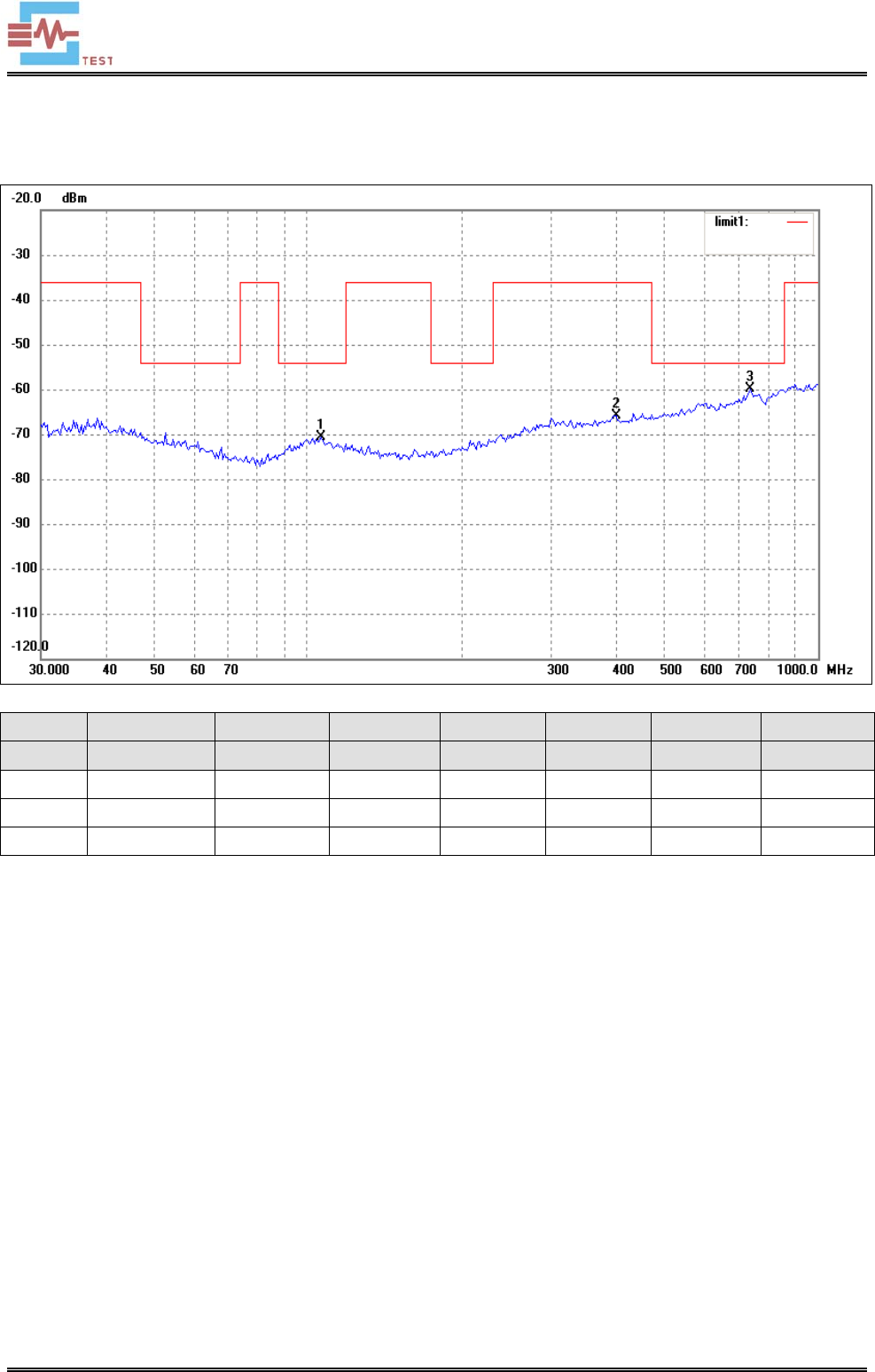
Test Mode: Transmitting-Middle channel (5805MHz)
Horizontal:
No. Frequency Reading Correct Result Limit Margin Remark
(MHz) (dBm) dB (dBm) (dBm) (dB)
1 106.0126 -88.06 17.32 -70.74 -54.00 -16.74 ERP
2 401.8385 -87.70 21.88 -65.82 -36.00 -29.82 ERP
3 734.4913 -86.89 26.98 -59.91 -54.00 -5.91 ERP
SEM.Test
Shenzhen SEM.Test Technology Co., Ltd.
REPORT NO.: STR15098069E-2 PAGE 17 OF 31 RF REPORT
Vert ica l:
No. Frequency Reading Correct Result Limit Margin Remark
(MHz) (dBm) dB (dBm) (dBm) (dB)
1 99.5281 -88.82 17.83 -70.99 -54.00 -16.99 ERP
2 734.4913 -87.28 26.98 -60.30 -54.00 -6.30 ERP
3 893.8567 -86.84 28.55 -58.29 -36.00 -22.29 ERP
SEM.Test
Shenzhen SEM.Test Technology Co., Ltd.
REPORT NO.: STR15098069E-2 PAGE 18 OF 31 RF REPORT
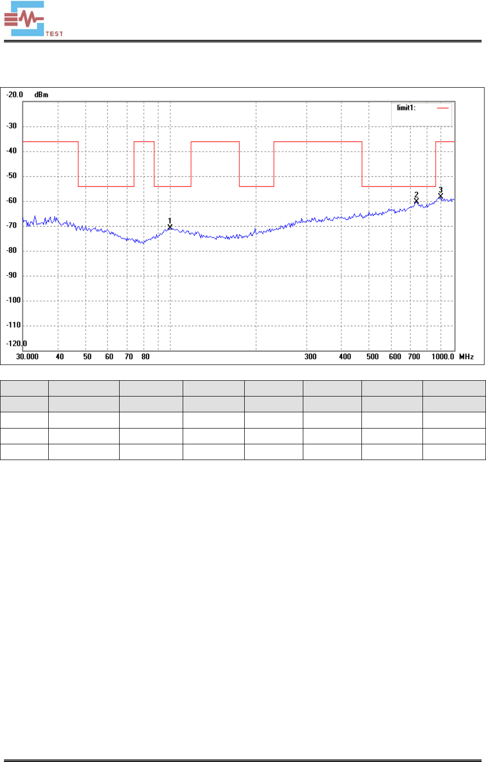
Test Mode: Transmitting-High channel (5825MHz)
Horizontal:
No. Frequency Reading Correct Result Limit Margin Remark
(MHz) (dBm) dB (dBm) (dBm) (dB)
1 103.8055 -88.41 17.55 -70.86 -54.00 -16.86 ERP
2 750.1083 -86.91 26.87 -60.04 -54.00 -6.04 ERP
3 851.0353 -87.11 27.70 -59.41 -54.00 -5.41 ERP
SEM.Test
Shenzhen SEM.Test Technology Co., Ltd.
REPORT NO.: STR15098069E-2 PAGE 19 OF 31 RF REPORT
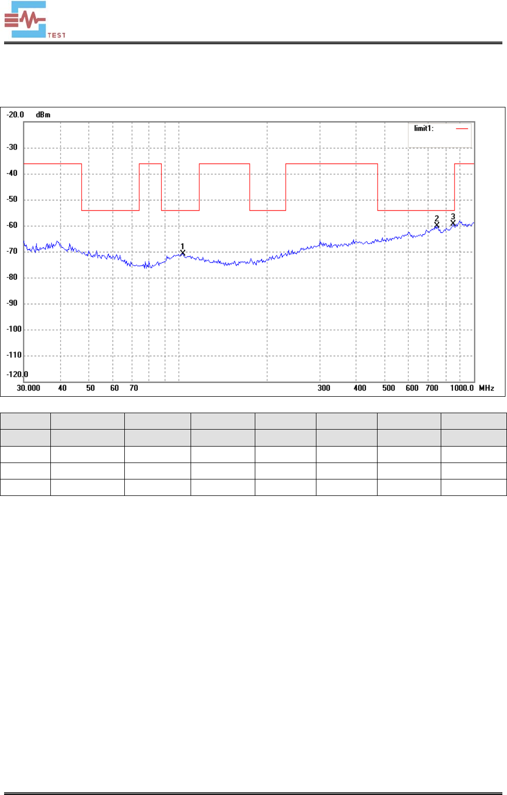
Vert ica l:
No. Frequency Reading Correct Result Limit Margin Remark
(MHz) (dBm) dB (dBm) (dBm) (dB)
1 100.2286 -87.78 17.92 -69.86 -54.00 -15.86 ERP
2 734.4913 -86.52 26.98 -59.54 -54.00 -5.54 ERP
3 851.0353 -87.46 27.70 -59.76 -54.00 -5.76 ERP
SEM.Test
Shenzhen SEM.Test Technology Co., Ltd.
REPORT NO.: STR15098069E-2 PAGE 20 OF 31 RF REPORT
Spurious Emission Above 1GHz
Frequency Reading Correct Result Limit Margin Polar
(MHz) (dBm) dB (dBm) (dBm) (dB) H/V
Low Channel-5775MHz
11550 -51.43 3.1 -48.33 -30 -18.33 H
17325 -53.45 4.2 -49.25 -30 -19.25 H
11550 -51.27 3.1 -48.17 -30 -18.17 V
17325 -53.75 4.2 -49.55 -30 -19.55 V
Middle Channel-5805MHz
11610 -51.28 3.1 -48.18 -30 -18.18 H
17415 -52.73 4.5 -48.23 -30 -18.23 H
11610 -51.36 3.1 -48.26 -30 -18.26 V
17415 -55.53 4.5 -51.03 -30 -21.03 V
High Channel-5825MHz
11650 -51.26 3.1 -48.16 -30 -18.16 H
17475 -55.54 4.5 -51.04 -30 -21.04 H
11650 -49.37 3.1 -46.27 -30 -16.27 V
17475 -54.46 4.5 -49.96 -30 -19.96 V
Note: Testing is carried out with frequency rang 30MHz to 40 GHz, which above 4th Harmonics are attenuated
more than 20dB below the permissible limits or the field strength is too small to be measured.
SEM.Test
Shenzhen SEM.Test Technology Co., Ltd.
REPORT NO.: STR15098069E-2 PAGE 21 OF 31 RF REPORT
6. Duty Cycle
6.1 Applicable Standard
Test is conducting under the description of ETSI EN 300 440-1 section 7.4. Where an acknowledgement is
required, the additional transmitter on-time shall be included and declared by the manufacturer.
6.2 Test Procedure
Test is conducting under the description of ETSI EN 300 440-1 section 7.4.2.
6.3 Environmental Conditions
Temperature: 22 °C
Relative Humidity: 45%
ATM Pressure: 1019 mbar
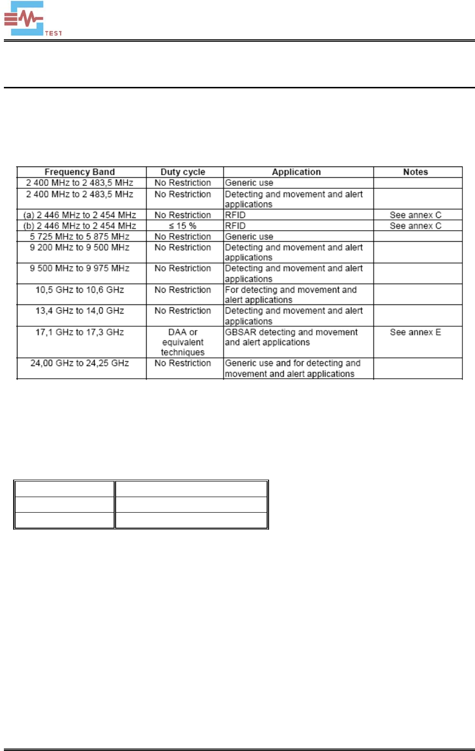
6.4 Summary of Test Results/Plots
For generic use devices operating at frequency range 5725-5875MHz, according to ETSI EN 300 440-1, the duty
cycle is no restriction.
SEM.Test
Shenzhen SEM.Test Technology Co., Ltd.
REPORT NO.: STR15098069E-2 PAGE 22 OF 31 RF REPORT
7. Receiver Spurious Emissions
7.1 Limit of Spurious Emissions
According to the ETSI EN 300 440-1 section 8.3.5, the power of any spurious emission shall not exceed 2 nW in the
range 25 MHz to 1 GHz and shall not exceed 20 nW on frequencies above 1 GHz.
7.2 Test Procedure
The EUT was placed on a nonmetal table which is 1.5 meter above the grounded reference plane and set to work
in receiving operation mode. For more detail please refer to the ETSI EN 300 440-1 section 8.3.4.
The EUT was operating at normal to represent worst case during final qualification test.
7.3 Environmental Conditions
Temperature: 22 °C
Relative Humidity: 45%
ATM Pressure: 1019 mbar
7.4 Summary of Test Results/Plots
According to the data sheet, the EUT complied with the EN 300 440 standards, and had the worst margin of:
-14.26 dB at 737.0714 MHz in the Vertical polarization, Receiving mode, 3Meters
SEM.Test
Shenzhen SEM.Test Technology Co., Ltd.
REPORT NO.: STR15098069E-2 PAGE 23 OF 31 RF REPORT
Receiver Spurious Emission From 30MHz To 1GHz
Test Mode: Receiving mode
Horizontal:
No. Frequency Reading Correct Result Limit Margin Remark
(MHz) (dBm) dB (dBm) (dBm) (dB)
1 43.6585 -71.77 -7.73 -79.50 -57.00 -22.50 ERP
2 56.3948 -71.04 -8.16 -79.20 -57.00 -22.20 ERP
3* 454.3100 -71.70 -2.11 -73.81 -57.00 -16.81 ERP
SEM.Test

Shenzhen SEM.Test Technology Co., Ltd.
REPORT NO.: STR15098069E-2 PAGE 24 OF 31 RF REPORT
Vertical
No. Frequency Reading Correct Result Limit Margin Remark
(MHz) (dBm) dB (dBm) (dBm) (dB)
1 330.1949 -83.22 6.80 -76.42 -57.00 -19.42 ERP
2 473.8347 -82.08 10.09 -71.99 -57.00 -14.99 ERP
3* 737.0714 -81.44 10.18 -71.26 -57.00 -14.26 ERP
Note: Testing is carried out with frequency rang 30MHz to 10th Harmonics frequency, which above 1GHz are
attenuated more than 20dB below the permissible limits or the field strength is too small to be measured.
SEM.Test
Shenzhen SEM.Test Technology Co., Ltd.
REPORT NO.: STR15098069E-2 PAGE 25 OF 31 RF REPORT
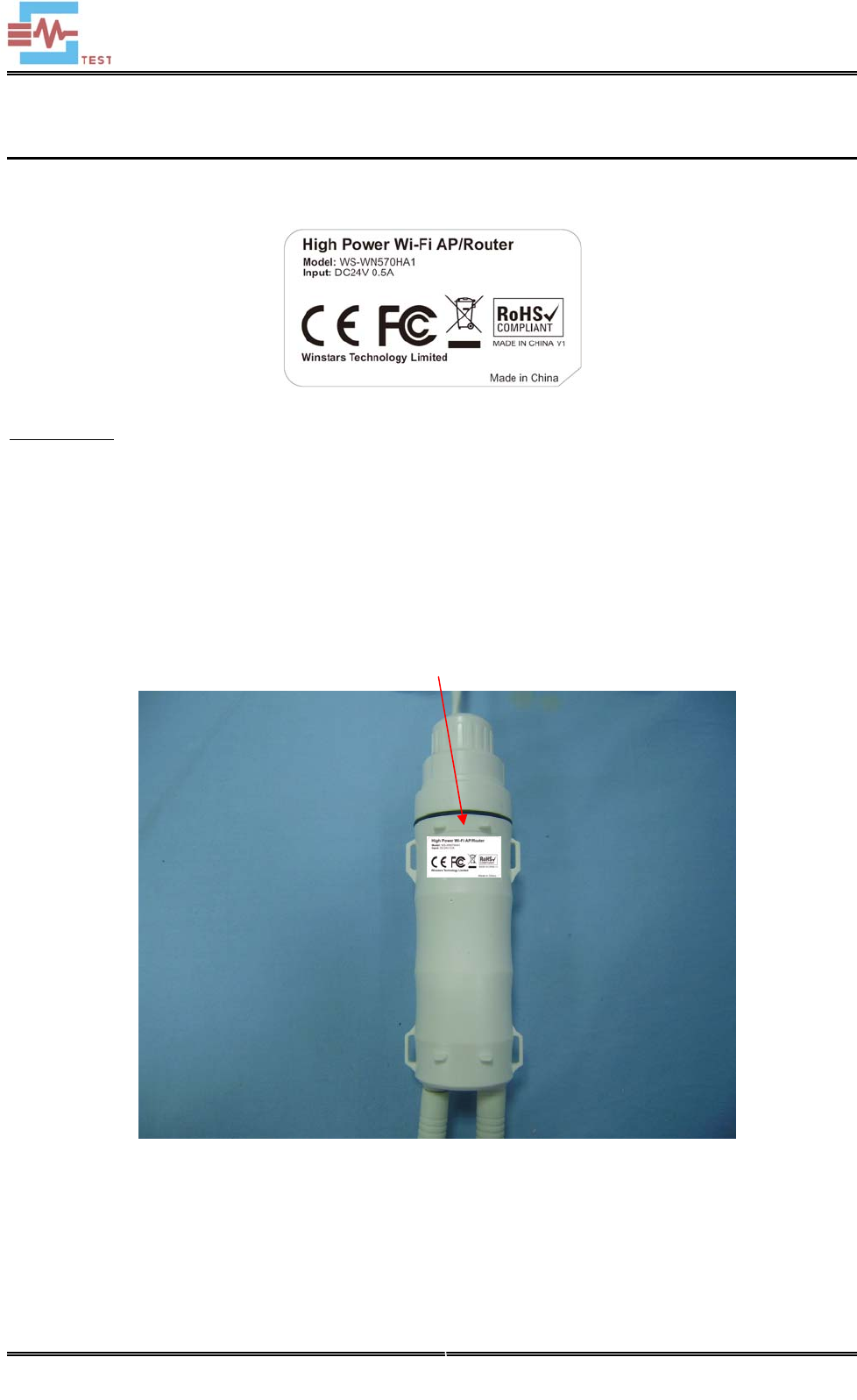
EXHIBIT 1 - PRODUCT LABELING
Proposed CE Label Format
Specifications: Text is Black in color and is justified. Labels are printed in indelible ink on permanent adhesive
backing or silk-screened onto the EUT or shall be affixed at a conspicuous location on the EUT. The ‘CE’ marking
must be affixed to the EUT or to its data plate. Where this is not possible or not warranted on account of the nature
of the apparatus, it must be affixed to the packaging, if any, and to the accompanying documents. The ‘CE’
marking must have a height of at least 5 mm. If the ‘CE’ marking is reduced or enlarged the proportions given in
the above graduated drawing must be respected.
Proposed Label Location on EUT
CE Label Location
SEM.Test
Shenzhen SEM.Test Technology Co., Ltd.
REPORT NO.: STR15098069E-2 PAGE 26 OF 31 RF REPORT
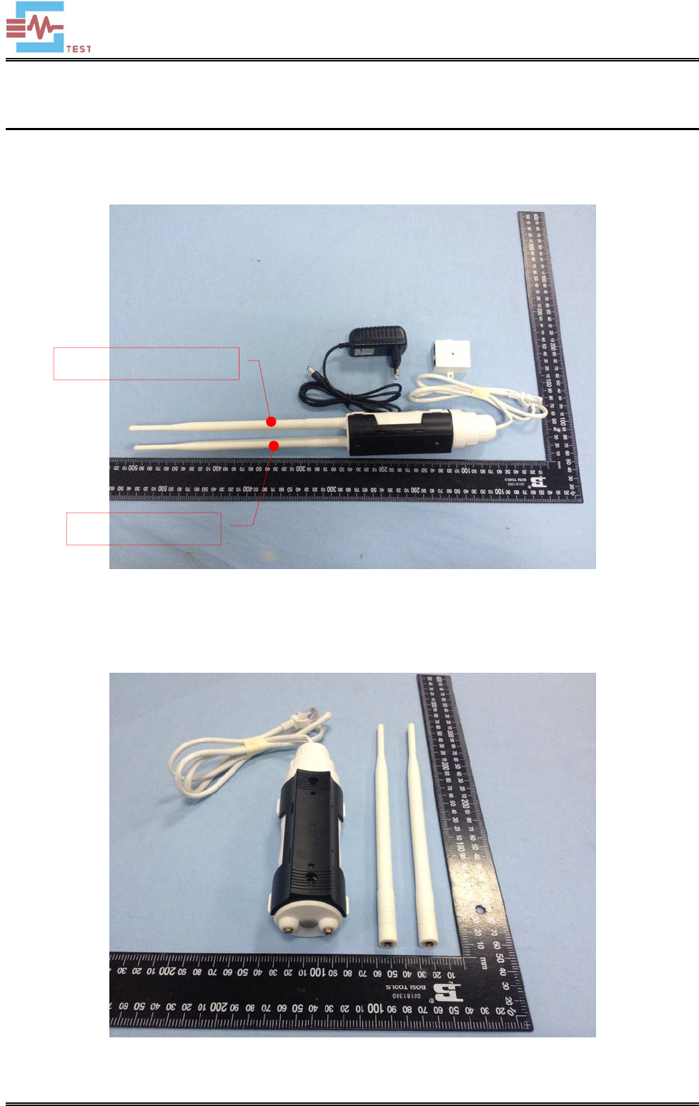
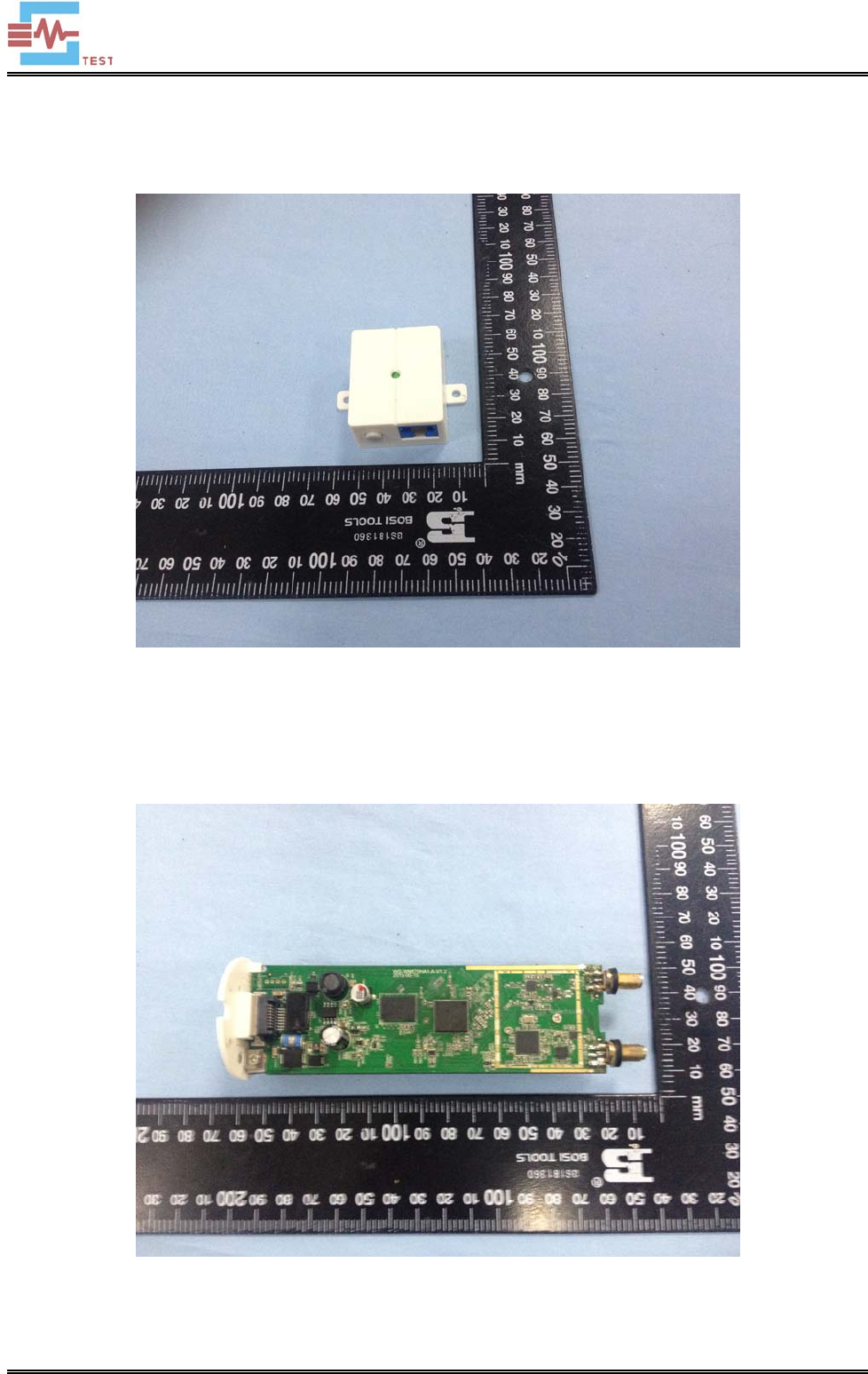
EXHIBIT 2 - EUT PHOTOGRAPHS
EUT View 1
EUT View 2
WIFI 5G/5.8G Antenna
WIFI 2.4G Antenna
SEM.Test
Shenzhen SEM.Test Technology Co., Ltd.
REPORT NO.: STR15098069E-2 PAGE 27 OF 31 RF REPORT
EUT View 3
EUT View 4
SEM.Test
Shenzhen SEM.Test Technology Co., Ltd.
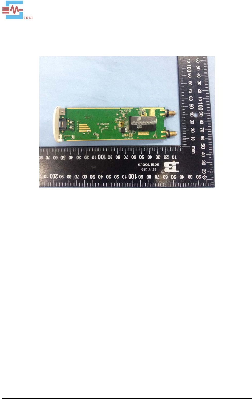
REPORT NO.: STR15098069E-2 PAGE 28 OF 31 RF REPORT
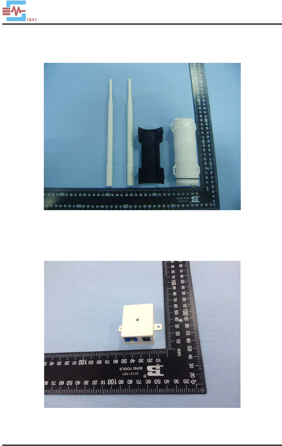
EUT View 5
EUT Housing and Board View 1
SEM.Test
Shenzhen SEM.Test Technology Co., Ltd.
REPORT NO.: STR15098069E-2 PAGE 29 OF 31 RF REPORT
EUT Housing and Board View 2
SEM.Test

Shenzhen SEM.Test Technology Co., Ltd.
REPORT NO.: STR15098069E-2 PAGE 30 OF 31 RF REPORT
EXHIBIT 3 - TEST SETUP PHOTOGRAPHS
Spurious Emission Test Setup (Below 1GHz)
Spurious Emission Test Setup (Above 1GHz)
SEM.Test
Shenzhen SEM.Test Technology Co., Ltd.
REPORT NO.: STR15098069E-2 PAGE 31 OF 31 RF REPORT
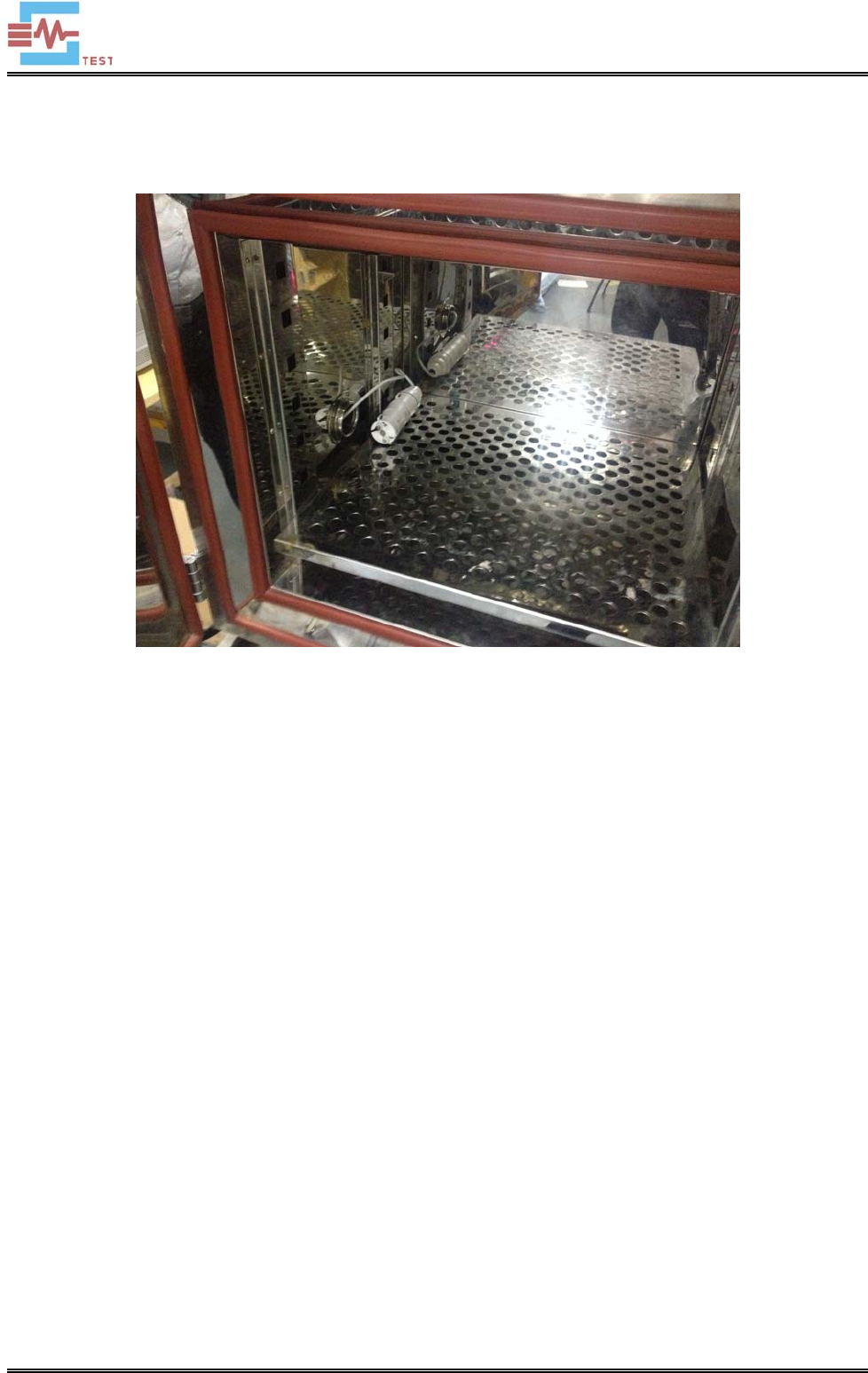
Extreme Conditions Test Setup
***** END OF REPORT *****
SEM.Test
