FD961025H01 FCC Certification
2016-04-11
: Pdf Fcc Certification FCC_Certification CertsReports 522328 ProductFiles
Open the PDF directly: View PDF ![]() .
.
Page Count: 25
Report No.: FD961025H01 1 Report Format Version 2.0.6
FCC DoC TEST REPORT
REPORT NO. :
FD961025H01
MODEL NO. :
GA-1325E, WFN-49, LCS-8037TXR2,
ENLGA-1320T
RECEIVED :
Oct. 25, 2007
TESTED :
Nov. 01, 2007
ISSUED :
Nov 05, 2007
APPLICANT :
NETRONIX , INC.
ADDRESS :
No. 945, Boai St., Jubei City,
Hsin-Chu,302,Taiwan, R.O.C.
ISSUED BY :
Advance Data Technology Corporation
LAB LOCATION :
No. 81-1, Lu Liao Keng, 9 Ling, Wu Lung Tsuen,
Chiung Lin Hsiang, Hsin Chu Hsien, Taiwan.
This test report consists of 25 pages in total. It may be duplicated completely for legal use
with the approval of the applicant. It should not be reproduced, except in full, without the
written approval of our laboratory. The client should not use it to claim product
endorsement by TAF, A2LA or any government agencies. The test results in the report only
apply to the tested sample.

Report No.: FD961025H01 2 Report Format Version 2.0.6
Table of Contents
1 CERTIFICATION.............................................................................................3
2 SUMMARY OF TEST RESULTS.....................................................................4
2.1 MEASUREMENT UNCERTAINTY..................................................................4
3 GENERAL INFORMATION.............................................................................5
3.1 GENERAL DESCRIPTION OF EUT................................................................5
3.2 GENERAL DESCRIPTION OF TEST MODE..................................................5
3.3 DESCRIPTION OF SUPPORT UNITS............................................................6
3.4 CONFIGURATION OF SYSTEM UNDER TEST.............................................7
4 EMISSION TEST.............................................................................................8
4.1 CONDUCTED EMISSION MEASUREMENT..................................................8
4.1.1 LIMITS OF CONDUCTED EMISSION MEASUREMENT................................8
4.1.2 TEST INSTRUMENTS....................................................................................8
4.1.3 TEST PROCEDURE.......................................................................................9
4.1.4 DEVIATION FROM TEST STANDARD...........................................................9
4.1.5 TEST SETUP................................................................................................10
4.1.6 EUT OPERATING CONDITIONS...................................................................11
4.1.7 TEST RESULTS............................................................................................12
4.2 RADIATED EMISSION MEASUREMENT.....................................................14
4.2.1 LIMITS OF RADIATED EMISSION MEASUREMENT...................................14
4.2.2 TEST INSTRUMENTS..................................................................................15
4.2.3 TEST PROCEDURE.....................................................................................16
4.2.4 DEVIATION FROM TEST STANDARD.........................................................16
4.2.5 TEST SETUP................................................................................................17
4.2.6 EUT OPERATING CONDITIONS..................................................................17
4.2.7 TEST RESULTS............................................................................................18
5 PHOTOGRAPHS OF THE TEST CONFIGURATION....................................22
6 INFORMATION ON THE TESTING LABORATORIES..................................24
7 APPENDIX A - MODIFICATIONS RECORDERS FOR ENGINEERING
CHANGES TO THE EUT BY THE LAB............................................................25

Report No.: FD961025H01 3 Report Format Version 2.0.6
1 CERTIFICATION
PRODUCT :
Gigabit Ethernet PCI Adapter
BRAND NAME :
NETRONIX, ViSTOR, Longshine, Encore
MODEL NO.:
GA-1325E, WFN-49, LCS-8037TXR2, ENLGA-1320T
TESTED :
Nov. 01, 2007
TEST SAMPLE :
MASS-PRODUCTION
APPLICANT :
NETRONIX , INC.
STANDARDS :
FCC Part 15: 2007, Subpart B, Class B
(section 15.31, 15.107 and 15.109)
ANSI C63.4-2003 (section 7 and 8)
ICES-003: 2004, Class B (section 4 and 5)
The above equipment (Model: GA-1325E) has been tested by Advance Data
Technology Corporation, and found compliance with the requirement of the
above standards. The test record, data evaluation & Equipment Under Test
(EUT) configurations represented herein are true and accurate accounts of the
measurements of the sample’s EMC characteristics under the conditions
specified in this report.
PREPARED BY
:
, DATE:
Nov 05, 2007
( Midoli Peng, Specialist )
TECHNICAL
ACCEPTANCE
:
, DATE:
Nov 05, 2007
Responsible for RF
( Ivan Peng, Deputy Manager )
APPROVED BY
:
, DATE:
Nov 05, 2007
( May Chen, Deputy Manager )

Report No.: FD961025H01 4 Report Format Version 2.0.6
2 SUMMARY OF TEST RESULTS
Standard Test Type Result Remarks
Conducted Test
PASS
Meets Class B Limit
Minimum passing margin is
-15.78 dB at 0.202 MHz
FCC Part 15,
Subpart B, Class B
ICES-003, Class B
Radiated Test PASS
Meets Class B Limit
Minimum passing margin is
-0.70 dB at 250.01 MHz
2.1 MEASUREMENT UNCERTAINTY
Where relevant, the following measurement uncertainty levels have been estimated
for tests performed on the EUT as specified in CISPR 16-4:
This uncertainty represents an expanded uncertainty expressed at approximately the
95% confidence level using a coverage factor of k=2.
Measurement Value
Conducted emissions 2.41 dB
Radiated emissions(30MHz-1GHz) 3.36 dB
Radiated emissions(1GHz-18GHz) 2.25 dB

Report No.: FD961025H01 5 Report Format Version 2.0.6
3 GENERAL INFORMATION
3.1 GENERAL DESCRIPTION OF EUT
PRODUCT Gigabit Ethernet PCI Adapter
MODEL NO. GA-1325E, WFN-49, LCS-8037TXR2, ENLGA-1320T
POWER SUPPLY
DC 5V from host equipment
POWER CORD NA
DATA CABLE
SUPPLIED NA
I/O PORTS RJ-45 port x 1
NOTE:
1. The EUT has four brand names and two model names, which are identical to
each other in all aspects except for the followings:
Brand Model Name Difference
NETRONIX GA-1325E
ViSTOR WFN-49
Longshine LCS-8037TXR2
Encore ENLGA-1320T
For different brands (models)
From the above models, model: GA-1325E was selected as representative
model for the test and its data was recorded in this report.
2. The EUT was pre-tested under the following modes:
Pre-test Mode Communication speed
Mode A 10 Mbps
Mode B 100 Mbps
Mode C 1000 Mbps
From the above modes, the worst cases were found in Mode C. Therefore only
the test data of the modes were recorded in this report.
3. For a more detailed features description, please refer to the manufacturer's
specifications or the User's Manual.
3.2 GENERAL DESCRIPTION OF TEST MODE
The EUT was tested under following test mode:
Test Mode Communication speed
Mode 1 1000 Mbps
Report No.: FD961025H01 6 Report Format Version 2.0.6
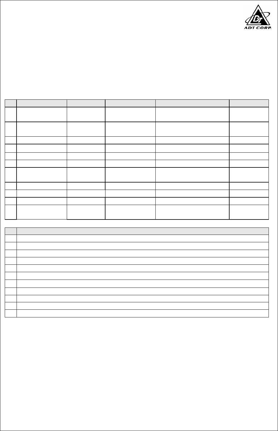
3.3 DESCRIPTION OF SUPPORT UNITS
The EUT has been tested as an independent unit together with other necessary
accessories or support units. The following support units or accessories were used to
form a representative test configuration during the tests.
No.
Product Brand Model No. Serial No. FCC ID
1
PERSONAL
COMPUTER DELL DCSM 294QL1S FCC DoC
2
LCD MONITOR DELL 2007FPb CN-0DC2144663363V-12W
S FCC DoC
3
PRINTER EPSON LQ-300+ DCGY017097 FCC DoC
4
MODEM ACEEX 1414 980020560 IFAXDM1414
5
KEYBOARD DELL SK-8115 MY-0J4635-71619-67V-0349
FCC DoC
6
MOUSE DELL M056UOA FOROOSNB FCC DoC
7
PERSONAL
COMPUTER DELL DCSM G84QL1S FCC DoC
8
LCD MONITOR ADI CM100 026058T10200636 A FCC DoC
9
KEYBOARD DELL SK-8115 MY-0J4635-71619-67V-0113
FCC DoC
10
MOUSE DELL M056UOA FOROOBSN FCC DoC
11
Gigabit Ethernet
PCI Adapter NETRONIX GA-1325E NA NA
No.
Signal cable description
1
NA
2
1.8 m braid shielded wire, terminated with VGA connector via metallic frame.
3
1.8 m braid shielded wire, terminated with DB25 connector via metallic frame, w/o core.
4
1.0 m braid shielded wire, terminated with DB25 and DB9 connector via metallic frame, w/o core.
5
1.2 m shielded cable, terminated with PS2 connector, w/o core.
6
1.2 m shielded cable, terminated with PS2 connector, w/o core.
7
NA
8
1.8 m braid shielded wire, terminated with VGA connector via metallic frame.
9
1.2 m shielded cable, terminated with PS2 connector, w/o core.
10
1.2 m shielded cable, terminated with PS2 connector, w/o core.
11
NA
Note: 1. The power cords of the above support units were unshielded (1.8m).
Report No.: FD961025H01 7 Report Format Version 2.0.6
3.4 CONFIGURATION OF SYSTEM UNDER TEST
NOTE: 1. Support units 7 ~ 11 were kept in the control room during the test.
CONTROL ROOM
UTP Cable (10m)
3. PRINTER
4. MODEM
2. MONITOR
5. KEYBOARD
6. MOUSE
1. PC
EUT
7. PC
11. Gigabit
Ethernet PCI
Adapter
8. MONITOR
9. KEYBOARD
10. MOUSE
Report No.: FD961025H01 8 Report Format Version 2.0.6
4 EMISSION TEST
4.1 CONDUCTED EMISSION MEASUREMENT
4.1.1 LIMITS OF CONDUCTED EMISSION MEASUREMENT
TEST STANDARD:
FCC Part 15: 2007, Subpart B (Section: 15.107)
ICES-003: 2004 (Class A: section 5.2)
(Class B: section 5.3)
FREQUENCY Class A (dBuV) Class B (dBuV)
(MHz) Quasi-peak
Average Quasi-peak
Average
0.15 - 0.5 79 66 66 - 56 56 - 46
0.50 - 5.0 73 60 56 46
5.0 - 30.0 73 60 60 50
NOTE: (1) The lower limit shall apply at the transition frequencies.
(2) The limit decreases linearly with the logarithm of the frequency in
the range 0.15 to 0.50 MHz
(3) All emanation from a class A/B digital device or system, including
any network of conductors and apparatus connected thereto, shall not exceed the level
of field strengths specified above.
4.1.2 TEST INSTRUMENTS
DESCRIPTION &
MANUFACTURER MODEL NO. SERIAL NO. CALIBRATED
UNTIL
ROHDE & SCHWARZ
Test Receiver ESCS 30 100287 Mar. 06, 2008
Line-Impedance Stabilization
Network(for EUT) ENV-216 100072 Oct. 20, 2008
Line-Impedance Stabilization
Network(for Peripheral) KNW-407 8-1395-12 Aug. 19, 2008
RF Cable (JETBAO) RG5B/U-6m COACAB-9KHz-3
0MHz Aug. 15, 2008
Terminator 50 1 Oct. 30, 2008
Software ADT_Cond_V7.3.2 NA NA
NOTE: 1. The calibration interval of the above test instruments is 12 months and the calibrations
are traceable to NML/ROC and NIST/USA.
2. The test was performed in ADT Shielded Room No. A.
3. The VCCI Con A Registration No. is C-817.

Report No.: FD961025H01 9 Report Format Version 2.0.6
4.1.3 TEST PROCEDURE
The basic test procedure was in accordance with ANSI C63.4-2003 (section 7),
CISPR 22 (section 9) and ICES-003: 2004 (section 4).
a. The EUT was placed 0.4 meters from the conducting wall of the shielded room
with EUT being connected to the power mains through a line impedance
stabilization network (LISN). Other support units were connected to the power
mains through another LISN. The two LISNs provide 50 Ohm/ 50uH of coupling
impedance for the measuring instrument.
b. Both lines of the power mains connected to the EUT were checked for maximum
conducted interference.
c. The frequency range from 150 kHz to 30 MHz was searched. Emission levels over
10dB under the prescribed limits could not be reported.
4.1.4 DEVIATION FROM TEST STANDARD
No deviation
Report No.: FD961025H01 10 Report Format Version 2.0.6
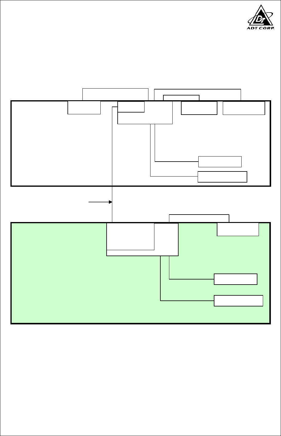
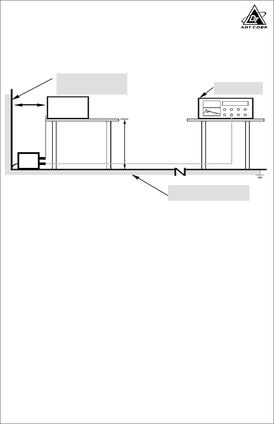
4.1.5 TEST SETUP
Note: 1.Support units were connected to second LISN.
2.Both of LISNs (AMN) are 80 cm from EUT and at least 80
from other units and other metal planes
Vertical Reference
Ground Plane
40cm
80cm
Test Receiver
Horizontal
Reference
Ground Plane
EUT
LISN
For the actual test configuration, please refer to the related item – Photographs of the Test
Configuration.

Report No.: FD961025H01 11 Report Format Version 2.0.6
4.1.6 EUT OPERATING CONDITIONS
1. Turn on the power of all equipment.
2. The EUT is installed in support unit 1 (PC).
3. PC ran a test program “Tfgen .exe” and “Ping .exe “to enable EUT
under transmission condition continuously via UTP cable..
4. PC sends "H" messages to monitor. Monitor scrolling "H" patterns
on its screen.
5. PC sends "H" messages to printer, and the printer prints them on
paper.
6. PC sends "H" messages to modem.
7. Repeat steps 2-6.
8. Repeat steps 2-3.
Report No.: FD961025H01 12 Report Format Version 2.0.6
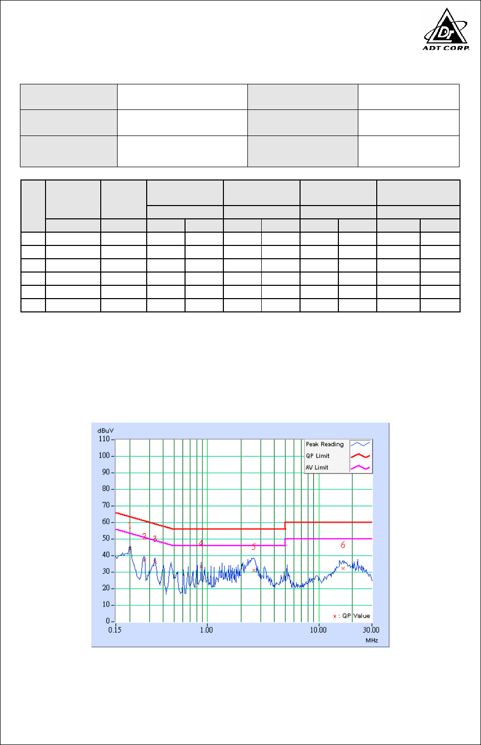
4.1.7 TEST RESULTS
TEST MODE Mode 1 6dB BANDWIDTH 9 kHz
INPUT POWER 120Vac, 60 Hz PHASE Line (L)
ENVIRONMENTAL
CONDITIONS
25 deg. C, 60% RH,
966 hPa TESTED BY Eagle Chen
Freq. Corr. Reading Value
Emission
Level Limit Margin
No
Factor
[dB (uV)] [dB (uV)] [dB (uV)] (dB)
[MHz] (dB) Q.P. AV. Q.P. AV. Q.P. AV. Q.P. AV.
1
0.201 0.40 43.14
- 43.54
- 63.58
53.58
-20.04
-
2
0.271 0.36 36.69
- 37.05
- 61.08
51.08
-24.03
-
3
0.338 0.33 35.07
- 35.40
- 59.26
49.26
-23.86
-
4
0.877 0.30 32.43
- 32.73
- 56.00
46.00
-23.27
-
5
2.611 0.33 30.38
- 30.71
- 56.00
46.00
-25.29
-
6
16.496 0.83 31.27
- 32.10
- 60.00
50.00
-27.90
-
REMARKS: 1. Q.P. and AV. are abbreviations of quasi-peak and average individually.
2. "-": The Quasi-peak reading value also meets average limit and
measurement with the average detector is unnecessary.
3. The emission levels of other frequencies were very low against the limit.
4. Margin value = Emission level - Limit value
5. Correction factor = Insertion loss + Cable loss
6. Emission Level = Correction Factor + Reading Value.
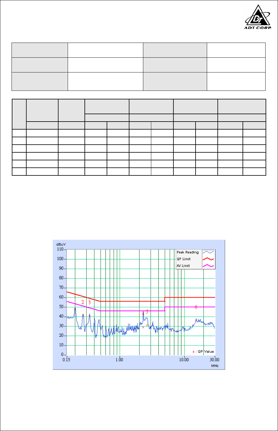
Report No.: FD961025H01 13 Report Format Version 2.0.6
TEST MODE Mode 1 6dB BANDWIDTH 9 kHz
INPUT POWER 120Vac, 60 Hz PHASE Neutral (N)
ENVIRONMENTAL
CONDITIONS
25 deg. C, 60% RH,
966 hPa TESTED BY Eagle Chen
Freq. Corr. Reading Value
Emission
Level Limit Margin
No
Factor
[dB (uV)] [dB (uV)] [dB (uV)] (dB)
[MHz] (dB) Q.P. AV. Q.P. AV. Q.P. AV. Q.P. AV.
1
0.202 0.40 47.37
- 47.77
- 63.55
53.55
-15.78
-
2
0.267 0.37 40.23
- 40.60
- 61.20
51.20
-20.61
-
3
0.338 0.33 39.82
- 40.15
- 59.26
49.26
-19.11
-
4
2.310 0.40 27.91
- 28.31
- 56.00
46.00
-27.69
-
5
2.658 0.40 30.34
- 30.74
- 56.00
46.00
-25.26
-
6
15.359 0.81 35.15
- 35.96
- 60.00
50.00
-24.04
-
REMARKS: 1. Q.P. and AV. are abbreviations of quasi-peak and average individually.
2. "-": The Quasi-peak reading value also meets average limit and
measurement with the average detector is unnecessary.
3. The emission levels of other frequencies were very low against the limit.
4. Margin value = Emission level - Limit value
5. Correction factor = Insertion loss + Cable loss
6. Emission Level = Correction Factor + Reading Value.
Report No.: FD961025H01 14 Report Format Version 2.0.6
4.2 RADIATED EMISSION MEASUREMENT
4.2.1 LIMITS OF RADIATED EMISSION MEASUREMENT
TEST STANDARD:
FCC Part 15: 2007, Subpart B (Section: 15.109)
ICES-003: 2004 (Class A: Section 5.4/Class B: Section 5.5)
FOR FREQUENCY BELOW 1000 MHz (47 CFR Part 15 Subpart B)
Class A (at 10m) Class B (at 3m)
FREQUENCY
(MHz) uV/m dBuV/m uV/m dBuV/m
30 – 88 90 39.1 100 40.0
88 – 216 150 43.5 150 43.5
216 - 960 210 46.4 200 46.0
Above 960 300 49.5 500 54.0
FOR FREQUENCY BELOW 1000 MHz (CISPR 22)
Class A (at 10m) Class B (at 10m)
FREQUENCY (MHz) dBuV/m dBuV/m
30 – 230 40 30
230 - 1000 47 37
Note: The limit for radiated test was performed according to CISPR 22, which was specified in
FCC PART 15 Subpart B 15.109(g) and ICES-003 clause 7.
LIMIT OF RADIATED EMISSION OF FCC PART 15, SUBPART B
FOR FREQUENCY ABOVE 1000 MHz
Class A (dBuV/m) (at 3m) Class B (dBuV/m) (at 3m
)
FREQUENCY (MHz)
PEAK AVERAGE PEAK AVERAGE
Above 1000 80.0 60.0 74.0 54.0
Note: (1) The lower limit shall apply at the transition frequencies.
(2) Emission level (dBuV/m) = 20 log Emission level (uV/m).
(3) All emanation from a class A/B digital device or system, including any network of
conductors and apparatus connected thereto, shall not exceed the level of field
strengths specified above.
Report No.: FD961025H01 15 Report Format Version 2.0.6
FREQUENCY RANGE OF RADIATED MEASUREMENT
(For unintentional radiators)
Highest frequency generated or
Upper frequency of measurement
used in the device or on which the
device operates or tunes (MHz)
Range (MHz)
Below 1.705 30
1.705 – 108 1000
108 – 500 2000
500 – 1000 5000
Above 1000 5th harmonic of the highest frequency
or 40 GHz, whichever is lower
4.2.2 TEST INSTRUMENTS
DESCRIPTION &
MANUFACTURER MODEL NO. SERIAL NO. CALIBRATED
UNTIL
*ADVANTEST Spectrum Analyzer R3271A 85060311 July 15, 2008
*HP Pre_Amplifier 8449B 3008A01922 Oct. 04, 2008
*ROHDE & SCHWARZ
Test Receiver ESCS 30 100027 Apr. 29, 2008
*CHASE Broadband Antenna CBL6112B 2798 Aug. 10, 2008
*Schwarzbeck Horn_Antenna BBHA9120 D123 Oct. 04, 2008
Schwarzbeck Horn_Antenna BBHA 9170 BBHA9170153 Jan. 25, 2008
SCHWARZBECK
Biconical Antenna VHBA9123 459 Jun. 08, 2009
SCHWARZBECK
Periodic Antenna UPA6108 1148 Jun. 08, 2009
*RF Switches MP59B M50867 July 03, 2008
*RF Cable(JETBAO) 9913-30M N-N
Cable
STACAB-30M-1G
Hz Aug. 10, 2008
*Software ADT_Radiated_V
7.6.15.7 NA NA
*EMCO Antenna Tower 2075-2 9712-2124 NA
*EMCO Turn Table 2081-1.53 9712-2030 NA
*CORCOM AC Filter MRI2030 107/108 NA
Note: 1. The calibration interval of the above test instruments is 12 months (36 months for
Periodic Antenna) and the calibrations are traceable to NML/ROC and NIST/USA.
2. * = These equipment are used for the final measurement.
3. The horn antenna, HP preamplifier (model: 8449B) and Spectrum Analyzer (model:
R3271A) are used only for the measurement of emission frequency above 1GHz if
tested.
4. The test was performed in ADT Open Site No. A.
5. The VCCI Site Registration No. is R-782.
6. The FCC Site Registration No. is 91097.
7. The CANADA Site Registration No. is IC 4824A-1.

Report No.: FD961025H01 16 Report Format Version 2.0.6
4.2.3 TEST PROCEDURE
The basic test procedure was in accordance with ANSI C63.4-2003 (section 8),
CISPR 22 (section 10) and ICES-003: 2004 (section 4).
a. The EUT was placed on the top of a rotating table 0.8 meters above the ground
at a 10-meter open field site. The table was rotated 360 degrees to determine the
position of the highest radiation.
b. The EUT was set 10 meters (3 meters above 1GHz) away from the interference-
receiving antenna, which was mounted on the top of a variable-height antenna
tower.
c. The antenna is a broadband antenna, and its height is varied from one meter to
four meters above the ground to determine the maximum value of the field
strength. Both horizontal and vertical polarizations of the antenna are set to make
the measurement.
d. For each suspected emission, the EUT was arranged to its worst case and then
the antenna was tuned to heights from 1 meter to 4 meters and the turn table
was turned from 0 degrees to 360 degrees to find the maximum reading.
e. The test-receiver system was set to quasi-peak detect function and specified
bandwidth with maximum hold mode when the test frequency is below 1 GHz.
f. The test-receiver system was set to peak and average detect function and
specified bandwidth with maximum hold mode when the test frequency is above
1 GHz. If the peak reading value also meets average limit, measurement with the
average detector is unnecessary.
NOTE:
1. The resolution bandwidth and video bandwidth of test receiver/spectrum analyzer is 120kHz
for Quasi-peak detection (QP) at frequency below 1GHz.
2. The resolution bandwidth is 1MHz and video bandwidth of test receiver/spectrum analyzer is
3MHz for Peak detection at frequency above 1GHz. The resolution bandwidth of test
receiver/spectrum analyzer is 1 MHz for Average detection (AV) at frequency above 1GHz.
3. For measurement of frequency above 1000 MHz, the EUT was set 3 meters away from the
interference-receiving antenna.
4.2.4 DEVIATION FROM TEST STANDARD
No deviation
Report No.: FD961025H01 17 Report Format Version 2.0.6
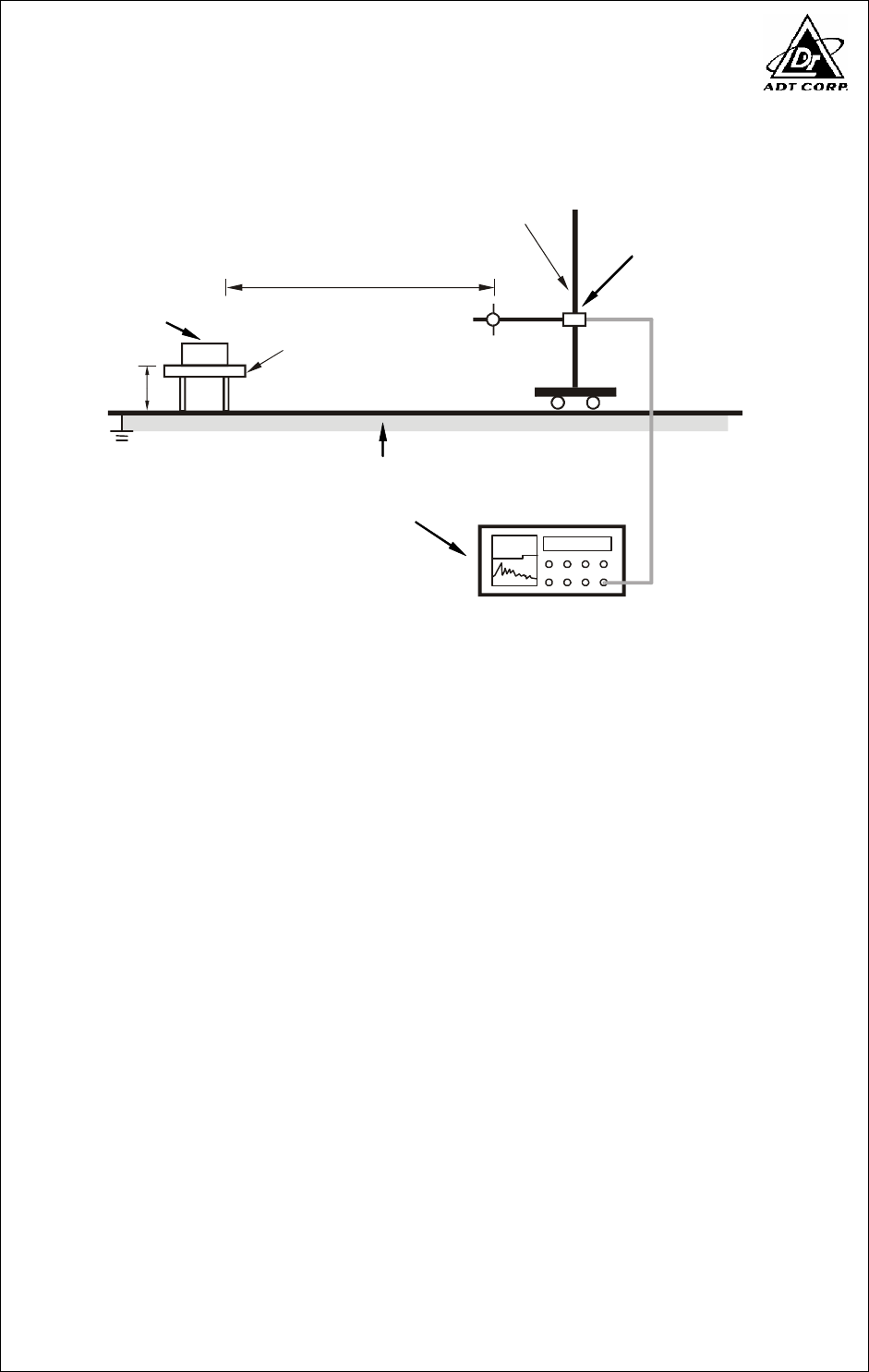
4.2.5 TEST SETUP
10m
Ant. Tower
1-
4m
Variable
Turn Table
EUT&
Support Units
Ground Plane
Test Receiver
80cm
3m-above 1GHz
For the actual test configuration, please refer to the related item – Photographs of the
Test Configuration.
4.2.6 EUT OPERATING CONDITIONS
Same as 4.1.6
Report No.: FD961025H01 18 Report Format Version 2.0.6
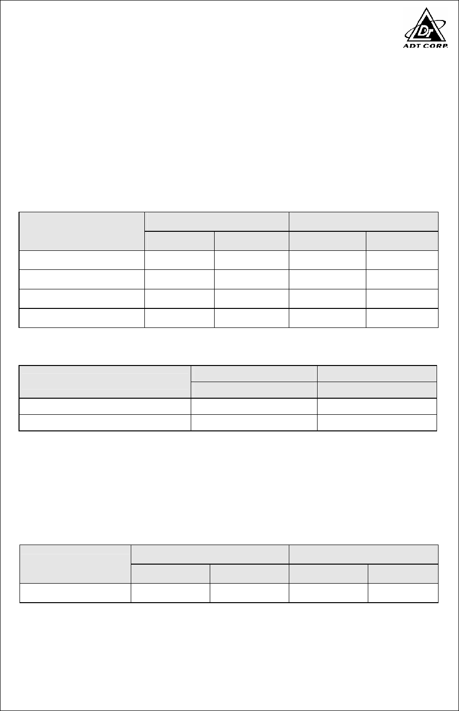
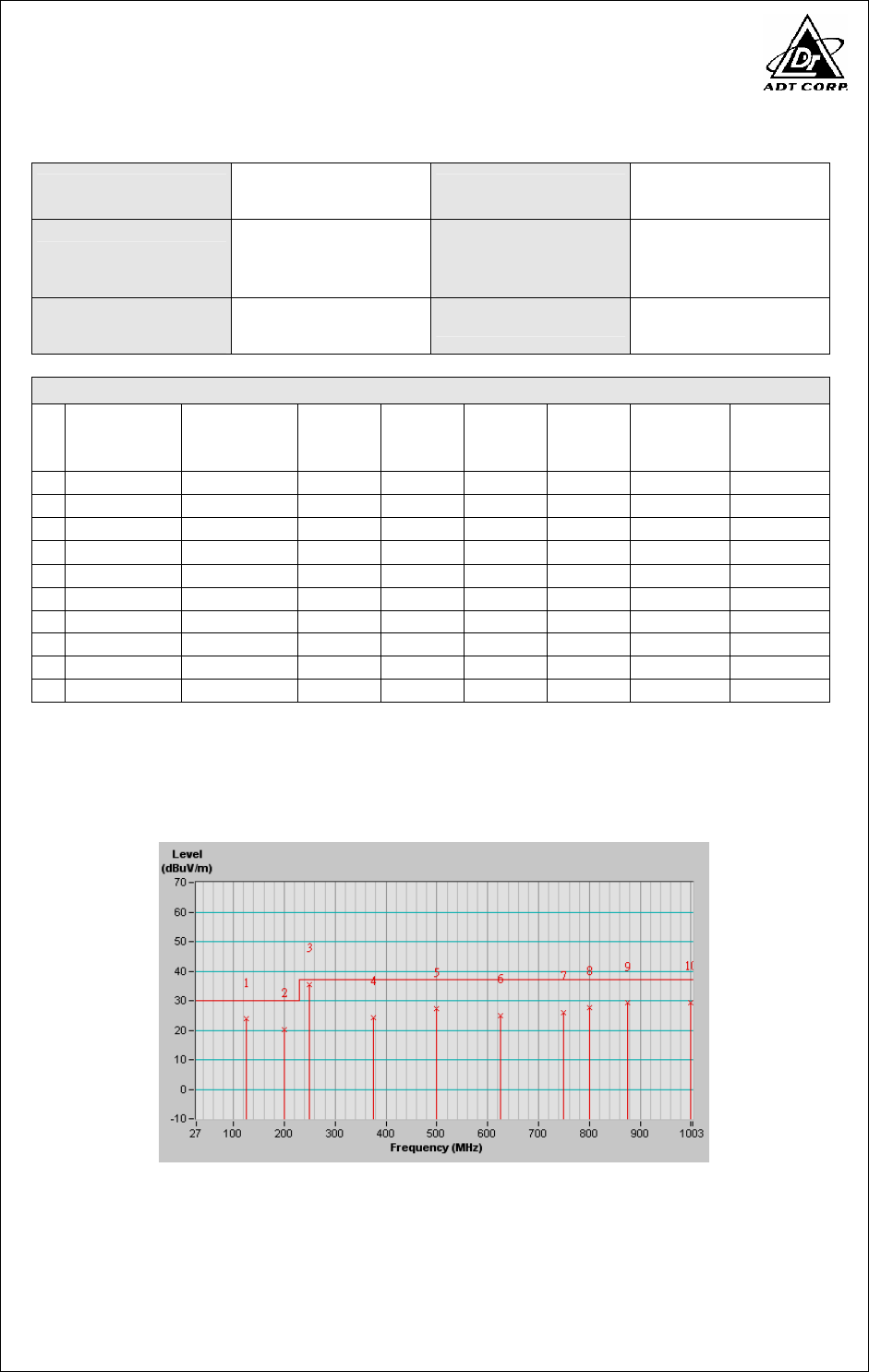
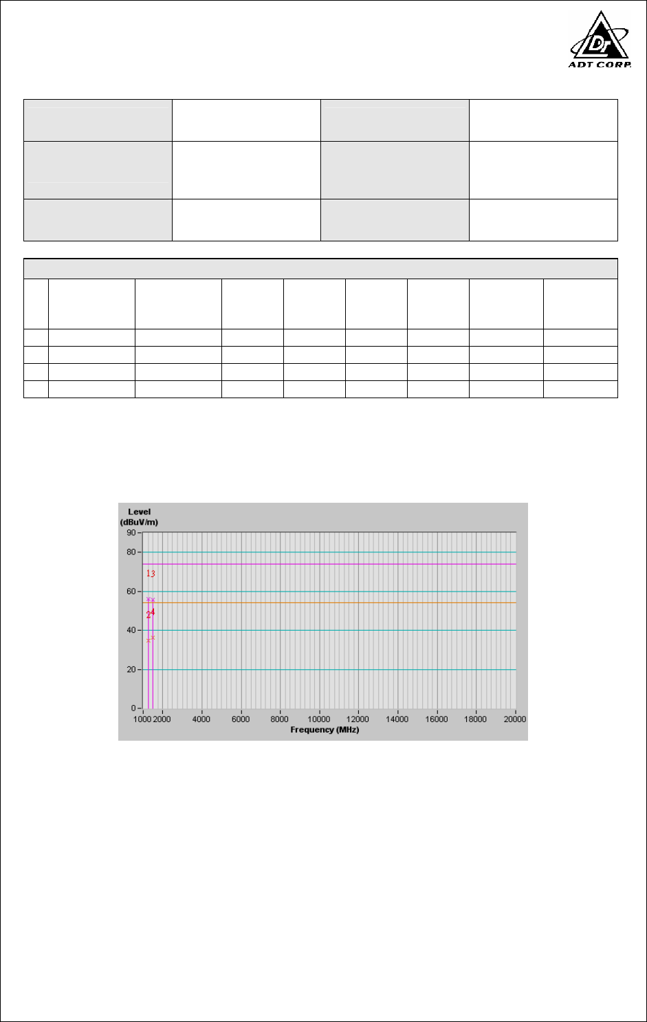
4.2.7 TEST RESULTS
TEST MODE Mode1 INPUT POWER 120Vac, 60Hz
FREQUENCY RANGE
30-1000 MHz
DETECTOR
FUNCTION &
BANDWIDTH
Quasi-Peak,
120kHz
ENVIRONMENTAL
CONDITIONS
23 deg. C, 71 % RH,
966 hPa TESTED BY Max Tseng
ANTENNA POLARITY & TEST DISTANCE: HORIZONTAL AT 10 M
No.
Freq.
(MHz)
Emission
Level
(dBuV/m)
Limit
(dBuV/m)
Margin
(dB)
Antenna
Height
(m)
Table
Angle
(Degree)
Raw
Value
(dBuV)
Correction
Factor
(dB/m)
1
125.00 23.79 QP 30.00 -6.21 4.00 H 291 10.90 12.89
2
200.00 20.25 QP 30.00 -9.75 4.00 H 179 8.95 11.30
3
250.01 35.43 QP 37.00 -1.57 4.00 H 121 21.83 13.60
4
375.00 24.22 QP 37.00 -12.78 2.40 H 309 6.86 17.36
5
500.00 27.17 QP 37.00 -9.83 1.60 H 145 6.87 20.30
6
625.00 25.06 QP 37.00 -11.94 1.42 H 155 1.78 23.28
7
750.00 25.97 QP 37.00 -11.03 1.00 H 329 0.72 25.25
8
800.00 27.55 QP 37.00 -9.45 1.00 H 42 1.42 26.13
9
875.02 29.22 QP 37.00 -7.78 1.00 H 94 1.90 27.32
10
1000.00 29.32 QP 37.00 -7.68 1.00 H 346 0.98 28.34
REMARKS: 1. Emission level(dBuV/m)=Raw Value(dBuV) + Correction Factor(dB/m)
2. Correction Factor(dB/m) = Antenna Factor (dB/m) + Cable Factor (dB)
3. The other emission levels were very low against the limit.
4. Margin value = Emission level – Limit value.
Report No.: FD961025H01 19 Report Format Version 2.0.6
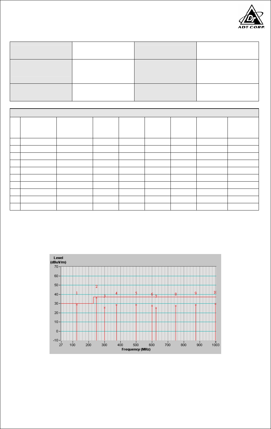
TEST MODE Mode1 INPUT POWER 120Vac, 60Hz
FREQUENCY RANGE
30-1000 MHz
DETECTOR
FUNCTION &
BANDWIDTH
Quasi-Peak,
120kHz
ENVIRONMENTAL
CONDITIONS
23 deg. C, 71 % RH,
966 hPa TESTED BY Max Tseng
ANTENNA POLARITY & TEST DISTANCE: VERTICAL AT 10 M
No.
Freq.
(MHz)
Emission
Level
(dBuV/m)
Limit
(dBuV/m)
Margin
(dB)
Antenna
Height
(m)
Table
Angle
(Degree)
Raw
Value
(dBuV)
Correction
Factor
(dB/m)
1
125.01 28.99 QP 30.00 -1.01 1.00 V 19 16.10 12.89
2
250.01 36.30 QP 37.00 -0.70 1.00 V 329 22.70 13.60
3
300.02 25.72 QP 37.00 -11.28 1.00 V 149 10.42 15.30
4
375.02 28.70 QP 37.00 -8.30 1.00 V 60 11.33 17.37
5
500.02 28.76 QP 37.00 -8.24 1.00 V 243 8.46 20.30
6
600.00 27.75 QP 37.00 -9.25 2.58 V 19 4.86 22.89
7
625.03 25.34 QP 37.00 -11.66 2.48 V 304 2.06 23.28
8
750.00 27.74 QP 37.00 -9.26 2.15 V 196 2.49 25.25
9
875.00 28.61 QP 37.00 -8.39 1.87 V 28 1.29 27.32
10
1000.00 29.62 QP 37.00 -7.38 1.57 V 246 1.28 28.34
REMARKS: 1. Emission level(dBuV/m)=Raw Value(dBuV) + Correction Factor(dB/m)
2. Correction Factor(dB/m) = Antenna Factor (dB/m) + Cable Factor (dB)
3. The other emission levels were very low against the limit.
4. Margin value = Emission level – Limit value.

Report No.: FD961025H01 20 Report Format Version 2.0.6
TEST MODE Mode1 INPUT POWER 120Vac, 60Hz
FREQUENCY RANGE
1000-2000 MHz
DETECTOR
FUNCTION &
BANDWIDTH
Peak(PK)/
Average(AV),
1 MHz
ENVIRONMENTAL
CONDITIONS
23 deg. C, 71 % RH,
966 hPa TESTED BY Max Tseng
ANTENNA POLARITY & TEST DISTANCE: HORIZONTAL AT 3 M
No.
Freq.
(MHz)
Emission
Level
(dBuV/m)
Limit
(dBuV/m)
Margin
(dB)
Antenna
Height
(m)
Table
Angle
(Degree)
Raw
Value
(dBuV)
Correction
Factor
(dB/m)
1
1250.00 55.80 PK 74.00 -18.20 1.00 H 241 25.68 30.12
2
1250.00 34.10 AV 54.00 -19.90 1.00 H 241 3.98 30.12
3
1500.00 54.60 PK 74.00 -19.40 1.46 H 344 23.39 31.21
4
1500.00 35.20 AV 54.00 -18.80 1.46 H 344 3.99 31.21
REMARKS: 1. Emission level(dBuV/m)=Raw Value(dBuV) + Correction Factor(dB/m)
2. Correction Factor(dB/m) = Antenna Factor (dB/m) + Cable Factor (dB)
3. The other emission levels were very low against the limit.
4. Margin value = Emission level – Limit value.
Report No.: FD961025H01 21 Report Format Version 2.0.6
TEST MODE Mode1 INPUT POWER 120Vac, 60Hz
FREQUENCY RANGE
1000-2000 MHz
DETECTOR
FUNCTION &
BANDWIDTH
Peak(PK)/
Average(AV),
1 MHz
ENVIRONMENTAL
CONDITIONS
23 deg. C, 71 % RH,
966 hPa TESTED BY Max Tseng
ANTENNA POLARITY & TEST DISTANCE: VERTICAL AT 3 M
No.
Freq.
(MHz)
Emission
Level
(dBuV/m)
Limit
(dBuV/m)
Margin
(dB)
Antenna
Height
(m)
Table
Angle
(Degree)
Raw
Value
(dBuV)
Correction
Factor
(dB/m)
1
1250.00 56.10 PK 74.00 -17.90 1.00 V 114 25.98 30.12
2
1250.00 34.80 AV 54.00 -19.20 1.00 V 114 4.68 30.12
3
1500.00 55.50 PK 74.00 -18.50 1.49 V 92 24.29 31.21
4
1500.00 36.30 AV 54.00 -17.70 1.49 V 92 5.09 31.21
REMARKS: 1. Emission level(dBuV/m)=Raw Value(dBuV) + Correction Factor(dB/m)
2. Correction Factor(dB/m) = Antenna Factor (dB/m) + Cable Factor (dB)
3. The other emission levels were very low against the limit.
4. Margin value = Emission level – Limit value.
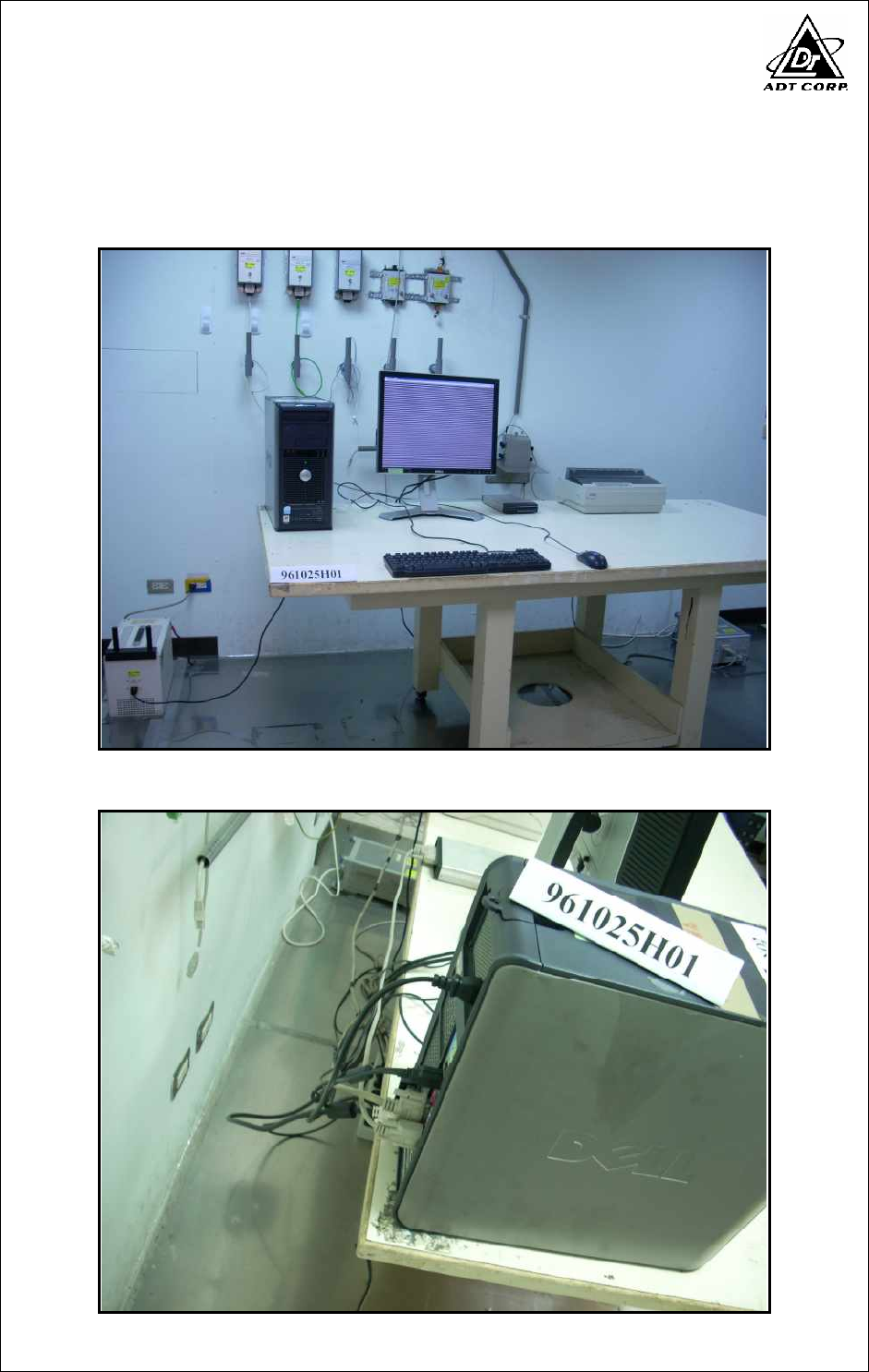
Report No.: FD961025H01 22 Report Format Version 2.0.6
5 PHOTOGRAPHS OF THE TEST CONFIGURATION
CONDUCTED EMISSION TEST
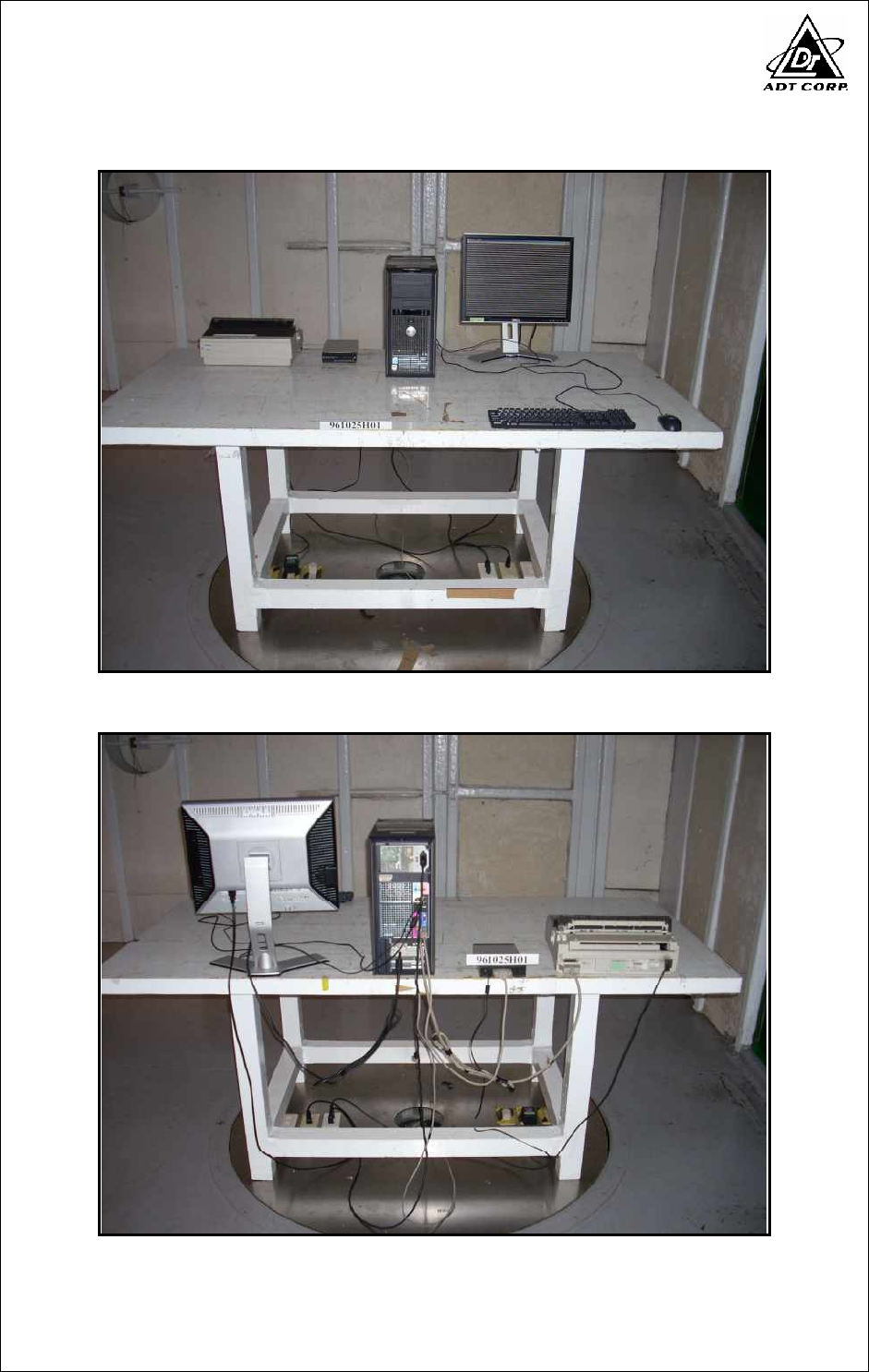
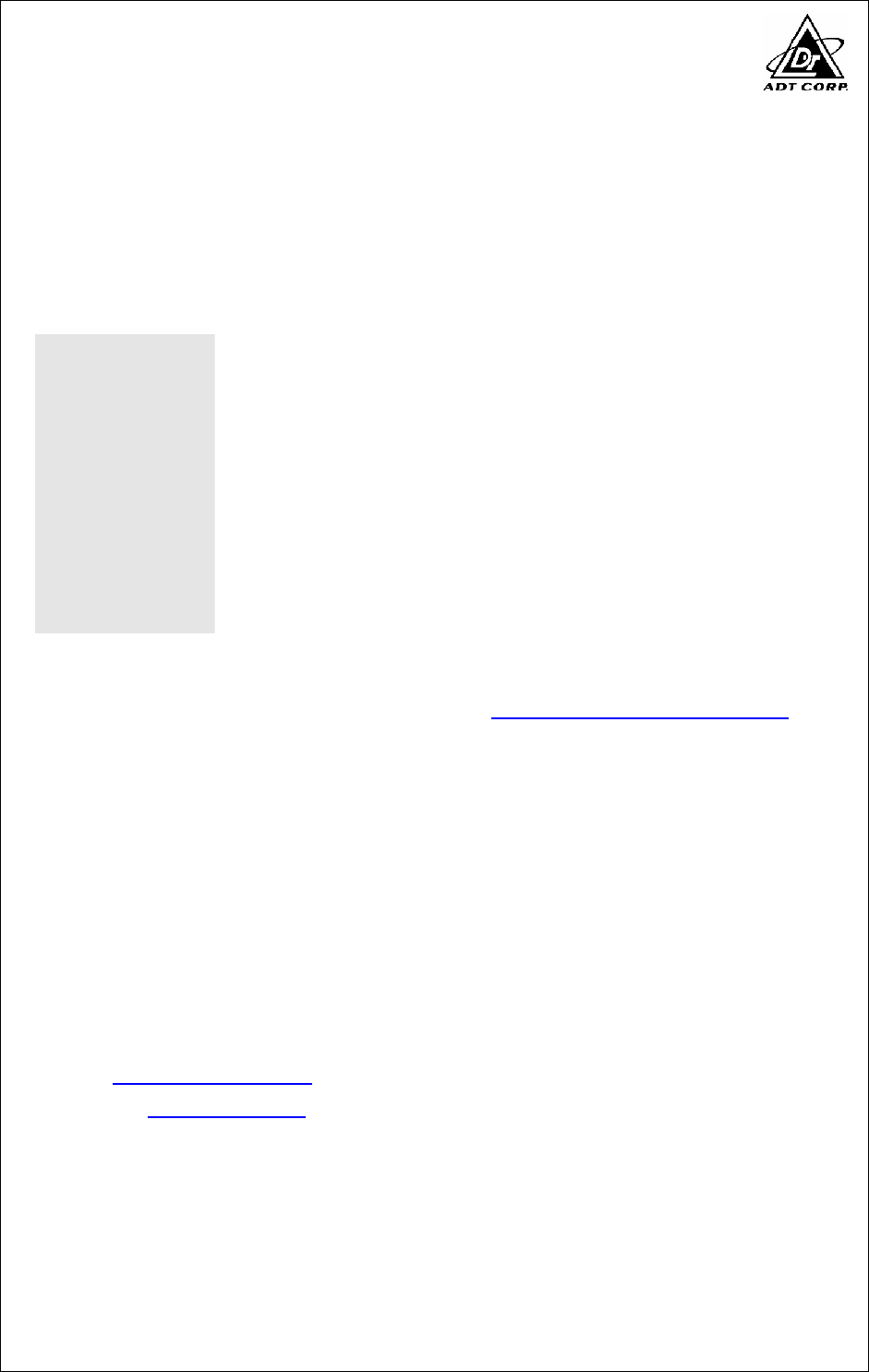
Report No.: FD961025H01 23 Report Format Version 2.0.6
RADIATED EMISSION TEST
Report No.: FD961025H01 24 Report Format Version 2.0.6
6 INFORMATION ON THE TESTING LABORATORIES
We, ADT Corp., were founded in 1988 to provide our best service in EMC, Radio,
Telecom and Safety consultation. Our laboratories are accredited and approved by
the following approval agencies according to ISO/IEC 17025:
USA FCC, UL, A2LA
Germany TUV Rheinland
Japan VCCI
Norway NEMKO
Canada INDUSTRY CANADA, CSA
R.O.C. TAF, BSMI, NCC
Netherlands Telefication
Singapore GOST-ASIA (MOU)
Russia CERTIS (MOU)
Copies of accreditation certificates of our laboratories obtained from approval
agencies can be downloaded from our web site: www.adt.com.tw/index.5/phtml.
If you have any comments, please feel free to contact us at the following:
Linko EMC/RF Lab:
Tel: 886-2-26052180
Fax: 886-2-26052943
Hsin Chu EMC/RF Lab:
Tel: 886-3-5935343
Fax: 886-3-5935342
Hwa Ya EMC/RF/Safety/Telecom Lab:
Tel: 886-3-3183232
Fax: 886-3-3185050
Email: service@adt.com.tw
Web Site: www.adt.com.tw
The address and road map of all our labs can be found in our web site also.

Report No.: FD961025H01 25 Report Format Version 2.0.6
7 APPENDIX A - MODIFICATIONS RECORDERS FOR
ENGINEERING CHANGES TO THE EUT BY THE LAB
No any modifications are made to the EUT by the lab during the test.
