GE Dishwasher EDW GSD PDW 31 9085
2013-04-09
: Pdf Ge Dishwasher - Edw-Gsd-Pdw - 31-9085 GE Dishwasher - EDW-GSD-PDW - 31-9085 GE, Camco, Hotpoint, Mofat
Open the PDF directly: View PDF ![]() .
.
Page Count: 44
PUB # 31-9085 09/01
MODEL SERIES:
TECHNICAL SERVICE GUIDE
GE Consumer Home Services Training
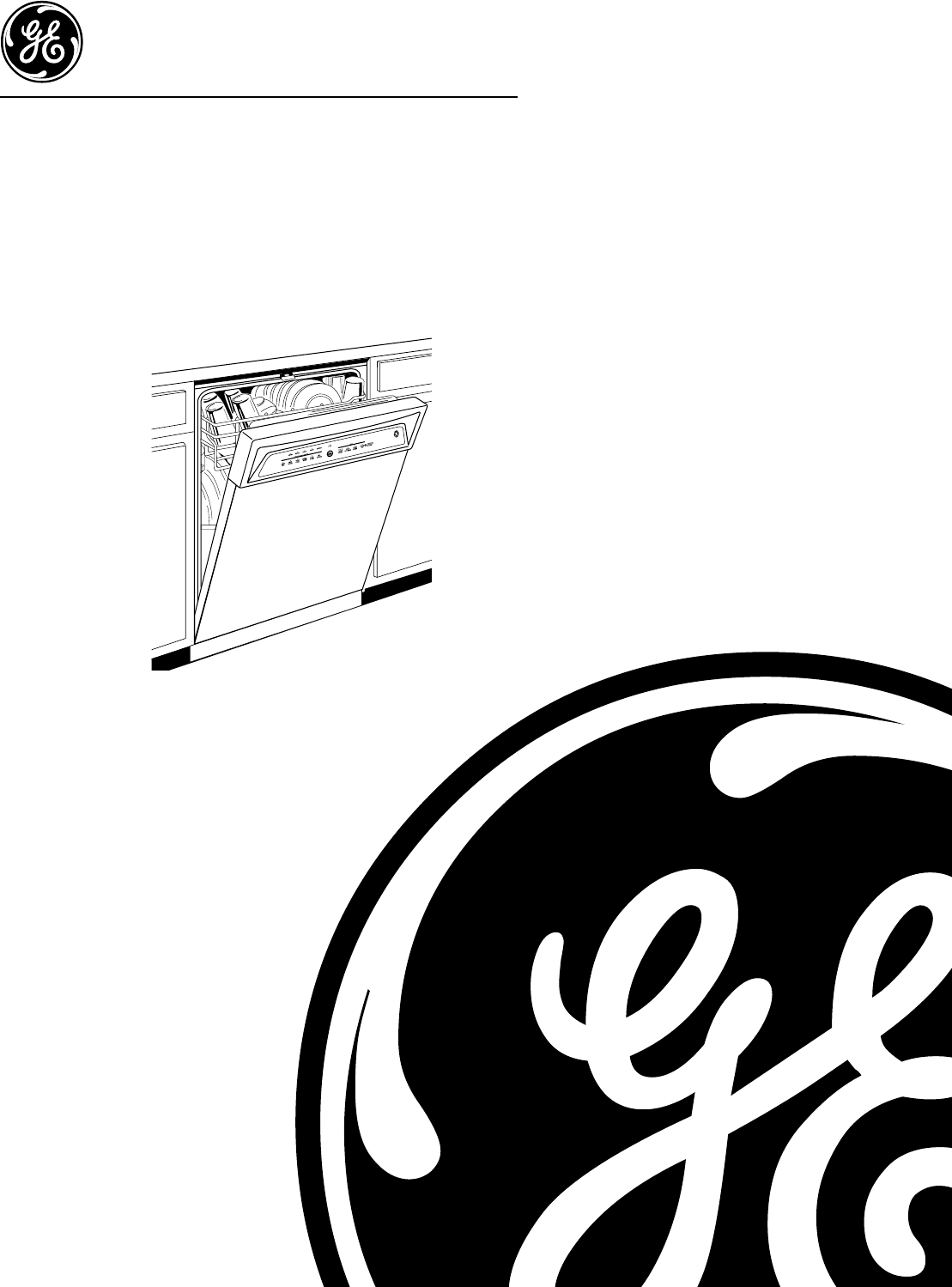
Triton XL
Dishwashers
EDW4000
EDW4060
GSD6200
GSD6300
GSD6600
GSD6660
GSD6700
PDW7300
PDW7700
PDW7800
PDW7880

IMPORTANT SAFETY NOTICE
The information in this service guide is intended for use by
individuals possessing adequate backgrounds of electrical,
electronic, and mechanical experience. Any attempt to repair a
major appliance may result in personal injury and property
damage. The manufacturer or seller cannot be responsible for the
interpretation of this information, nor can it assume any liability in
connection with its use.
WARNING
To avoid personal injury, disconnect power before servicing this prod-
uct. If electrical power is required for diagnosis or test purposes,
disconnect the power immediately after performing the necessary
checks.
RECONNECT ALL GROUNDING DEVICES
If grounding wires, screws, straps, clips, nuts, or washers used to
complete a path to ground are removed for service, they must be
returned to their original position and properly fastened.
GE Consumer Home Services Training
Technical Service Guide
Copyright © 2001
All rights reserved. This service guide may not be reproduced in whole or in part
in any form without written permission from the General Electric Company.
!

– 1 –
Table of Contents
Table of Contents
Introduction ......................................................................................................... 2
Nomenclature ...................................................................................................... 3
Control Panel Features5
Profile Models................................................................................................. 4
GE Models....................................................................................................... 6
Component Locator Views .................................................................................. 9
Dishwasher Components 5
Door Components ........................................................................................ 13
Escutcheon Keypad Assembly .................................................................... 13
Control Module ............................................................................................. 14
Detergent/Rinse Module ............................................................................. 14
Stainless Steel Bowed Panel (on some models) ...................................... 15
Door Interlock Switch................................................................................... 16
Bottom Door Seal ......................................................................................... 17
Drain System ................................................................................................. 17
Circulation System ....................................................................................... 18
Fill Funnel...................................................................................................... 20
Calrod® Heating Element ............................................................................. 20
Turbidity Sensor ........................................................................................... 21
Water Valve and Flood Switch ..................................................................... 22
Active Vent .................................................................................................... 23
Flashing Display Lights X .................................................................................. 24
Service Mode X.................................................................................................. 25
Factory Test Mode X.......................................................................................... 26
Washability Complaints...................................................................................... 27
Cycle Progression Charts ................................................................................. 28
Wiring Diagram X................................................................................................ 29
Parts List ............................................................................................................. 30
Reviewz .............................................................................................................. 38
Warrantyx
Profile Models............................................................................................... 39
GE Models..................................................................................................... 40
– 2 –
Introduction
The new Triton XL Dishwashers are packed with
features to get your dishes cleaner, pots and pans
spotless, and keep your kitchen quieter... and with
a power usage of 477 kWhr/yr, they have an
“EnergyStar” rating.
The Triton XL Dishwashers have 3 wash arms that
provide complete coverage, eliminating pre-
rinsing, soaking, and scrubbing. The ExtraCleanTM
sensor incorporates a thermistor Auto Temp
control and measures the water turbidity in 5
levels of cleanliness. The 100% triple-water filtra-
tion, with extra fine filter, eliminates recirculating
food particles. The PiranhaTM hard food disposer
grinds and pulverizes any other food particles.
Triton XL Dishwashers run quieter thanks to our
QuietPowerTM motor, PermaTuf® tub, and the
QuietPower IV sound insulation, Thinstall.
The dual wattage Calrod® heater draws 835 W
when it is wet to heat the water faster and, during
the drying cycle, drops to 700 W for gentler drying.
The information on the following pages will help
you service these new Triton XL Dishwashers
effectively and efficiently.
– 3 –
Model Designator
Designates features–the higher
the number, the more features.
Nomenclature
Model Number
Serial Number
The first two characters of the serial number
identify the month and year of manufacture.
Example: AA123456S = January, 2001
A - JAN 2005 - H
D - FEB 2004 - G
F - MAR 2003 - F
G - APR 2002 - D
H - MAY 2001 - A
L - JUN 2000 - Z
M - JUL 1999 - V
R - AUG 1998 - T
S - SEP 1997 - S
T - OCT 1996 - R
V - NOV 1995 - M
Z - DEC 1994 - L
Note: The service information sheet is located
under the control panel.
The letter designating the
year repeats every 12
years.
Example:
T - 1974
T - 1986
T - 1998
P D W 7 3 0 0 G 0 0 W W
Brand
P = Profile
E = General Electric - NATM
G = General Electric
Product Type
CD - Counter Top DW = Dishwasher
SD = Standard SC = Convertable
SM = Spacemaker SS = Compact (18 in.)
RF = Retrofit HD = Home Depot Derivative
Exterior Color
BB = Black
CC = Bisque
SS = Stainless Steel
WW = White
The serial plate of your dishwasher is
located on the tub wall just inside the
door.
Model Year Designator
Engineering Model Suffix
Nomenclature
– 4 –
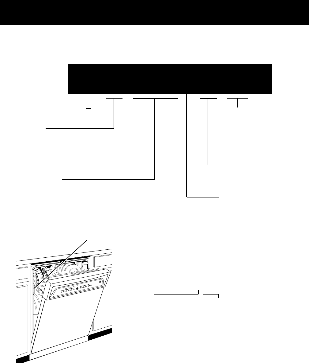
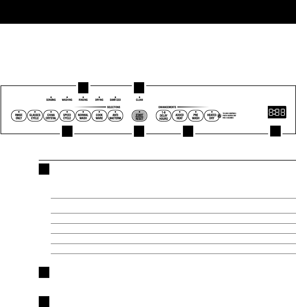
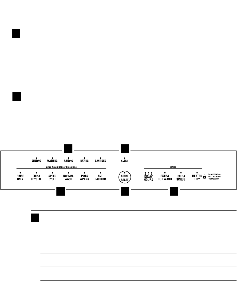
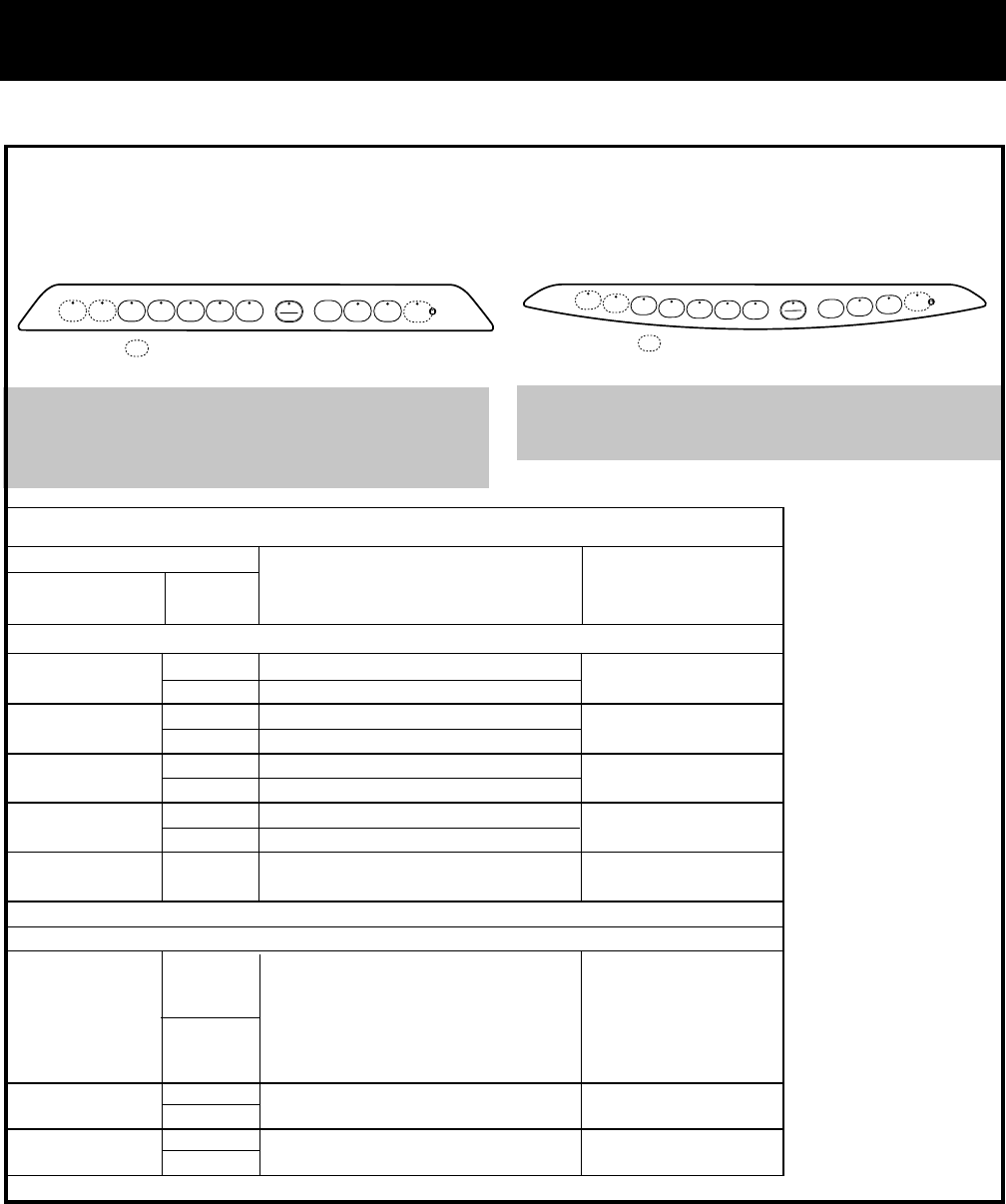
Control Panel Features
Throughout this manual, features and appearance may vary from your model.
Profile Models
Control Settings
Status Indicator Lights
The Status display tells you what’s happening while the dishwasher is in operation and may flash,
indicating a malfunction (see page 6). The lights will come
ON
indicating the sequence of
operation the dishwasher is in.
SENSING Displayed while the ExtraClean™ Sensor is measuring the amount of soil and temperature of water.
The dishwasher will adjust the selected cycle to achieve optimal performance.
WASHING Displayed during prewash and main wash periods.
RINSING Displayed during rinse periods.
DRYING Displayed during
HEATED DRY
.
SANITIZED Displayed when cycle has met sanitization conditions. Light remains
ON
until door is opened.
CLEAN Displayed when a wash cycle is complete. The light will remain
ON
until door is opened.
Time Remaining Display
(on some models)
Displays the minutes remaining until the cycle is complete. The display may adjust the remaining
time while the Sensing light is on.
Selections
The light above the selected pad will be ON to indicate which WASH CYCLE has been selected.
ANTI-BACTERIA Heavy 10.0 gal., 93 min.
Medium 8.6 gal., 90 min.
Light 7.2 gal., 90 min.
This cycle raises the water temperature in the final rinse to sanitize your dishware. The cycle
length will vary depending on the temperature of your inlet water.
NOTE: The Anti-Bacteria cycle is monitored for sanitization requirements. If the cycle is
interrupted during or after the main wash portion or if the incoming water temperature is so low
that adequate water heating cannot be achieved, the sanitizing conditions may not be met. In
these cases, the sanitized light will not illuminate at the end of the cycle.
NOTE: NSF certified residential dishwashers are not intended for licensed food establishments.
1
2
1 6
2
453
3
8
TIME REMAINING

– 5 –
COOK Heavy 11.4 gal., 95 min.
WARE Medium 10.0 gal., 71 min.
Light 10.0 gal., 66 min.
This cycle is meant for heavily soiled dishes or cookware with dried-on or baked-on soils. This
cycle may not remove burned-on foods. Everyday dishes are safe to be used in this cycle.
NORMAL WASH Heavy 9.9 gal., 74 min.
Medium 7.0 gal., 61 min.
Light 5.6 gal., 48 min.
This cycle is for medium/heavily soiled dishes and glassware.
SPEED CYCLE Heavy 9.3 gal., 36 min.
Medium 7.2 gal., 36 min.
Light 5.7 gal., 33 min.
This cycle is for everyday dishes and glassware.
CHINA CRYSTAL Heavy 10.0 gal., 49 min.
Medium 7.2 gal., 36 min.
Light 7.2 gal., 36 min.
This cycle is for lightly soiled china and crystal.
GLASSES Heavy 10.0 gal., 45 min.
(on some models) Medium 7.2 gal., 33 min.
Light 7.2 gal., 32 min.
This cycle is specifically designed for glasses.
RINSE ONLY Heavy 2.9 gal., 7 min.
Light 1.4 gal., 3 min.
For rinsing partial loads that will be washed later. Do not use detergent with this cycle.
NOTE:
This dishwasher is equipped with an ExtraClean™Sensor with automatic temperature
control; therefore cycle length and time may vary depending on soil and temperature conditions.
NOTE:
Only the Anti-Bacteria cycle has been designed to meet the requirements of Section 6,
NSF 184 for soil removal and sanitization efficacy
.
Enhancements
The light above the selected pad will be ON to indicate which ENHANCEMENT has been selected.
PRE For use with heavily soiled and/or dried-on, baked-on soils. This option
MUST
be selected
WASH
PRIOR
to starting the cycle.
This option adds 16 minutes to the cycle time. NOTE:
Cannot
be selected with
RINSE ONLY
cycle.
HEATED DRY Shuts off the drying heat option. Dishes air dry naturally and energy is saved. For faster air dry,
Light OFF
you can prop the door open after the
CLEAN
light illuminates.
HEATED DRY Turns the heater on for fast drying. This will extend the time to your wash cycle by 8 minutes
Light ON
for the
SPEED CYCLE
and 20 minutes for all other cycles.
NOTE:
Cannot be selected with
RINSE ONLY
cycle.
LOCK
You can lock the controls to prevent any selections from being made. Or you can lock the
controls after you have started a cycle.
Children cannot accidentally start dishwasher by touching pads with this option
selected.
To unlock the dishwasher controls, press and hold the
HEATED DRY
pad for 3 seconds. To lock
the dishwasher, press and hold the
HEATED DRY
pad for 3 seconds. The light above the
LOCK
pad will turn off.
ADDED HEAT When selected, the
NORMAL WASH
cycle will run longer with heating elements on to
improve both wash and dry performance.
NOTE:
Cannot be selected with
RINSE ONLY
cycle.
4
– 6 –
Start
Close the dishwasher door and select the
cycle and desired enhancements. Touch the
START/RESET
pad to begin the cycle. Water fill
begins, and approximately 60 seconds later the
wash action begins.
NOTE:
The dishwasher remembers your last cycle so
you don’t have to reprogram each time. When the
dishwasher door is fully closed, the control panel
lights will display the last settings you selected.
If you don’t want to change any of the settings,
simply touch the
START/RESET
pad to begin the
cycle.
If the door is closed the indicator lights will turn off
if the
START/RESET
pad is not selected within two
minutes. To activate the display, open and close the
door or press any pad.
Also, if a power failure occurs,
NORMAL
and
HEATED
DRY
will automatically be programmed. Make any
new selections and touch the
START/RESET
pad to
begin the cycle.
Clean
The
CLEAN
light is illuminated when a wash cycle is
complete. The light will stay
ON
until the door is
opened.
5
6
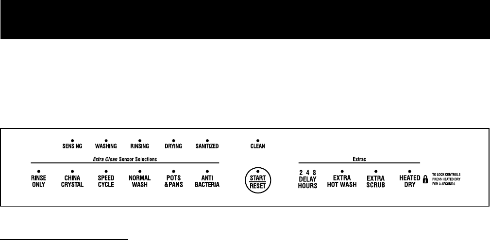
GE Models
DELAY HOURS You can delay the start of a wash cycle for up to 9 hours (on some models). Press the
DELAY
HOURS
pad to choose the number of hours you want to delay the start of the cycle, then press
START/RESET
. The machine will count down and start automatically at the correct time.
Pressing
START/RESET
a second time will cancel the
DELAY START
selection.
NOTE:
If you forget to fully close the door a reminder signal will beep until you do so.
RESET To change a cycle after washing starts, touch the
START/RESET
pad to cancel the cycle.
The
START/RESET
light will flash while the water is pumped out if needed. This takes
approximately 90 seconds. When the light stops flashing, the dishwasher can be reprogrammed
and restarted.
You can locate your model number on the tub wall just inside the door.
Throughout this manual, features and appearance
may vary from your model.
Control Settings
Status Indicator Lights
The Status display tells you what’s happening while the dishwasher is in operation and may flash,
indicating a malfunction (see page 6). The lights will come
ON
indicating the sequence of
operation the dishwasher is in.
SENSING Displayed while the ExtraClean™ Sensor is measuring the amount of soil and temperature of water.
(on some models)
The dishwasher will adjust the selected cycle to achieve optimal performance.
WASHING Displayed during prewash and main wash periods.
(on some models)
RINSING Displayed during rinse periods.
(on some models)
DRYING Displayed during
HEATED DRY
.
(on some models)
SANITIZED Displayed when cycle has met sanitization conditions. Light remains
ON
until door is opened.
CLEAN Displayed when a wash cycle is complete. The light will remain
ON
until door is opened.
1
1 5
3
4
2
8

– 7 –
ExtraClean™ Sensor Selections
The light above the selected pad will be ON to indicate which ExtraClean™ Sensor Selection has been
selected.
ANTI-BACTERIA Heavy 10.0 gal., 93 min.
Medium 8.6 gal., 90 min.
Light 7.2 gal., 90 min.
This cycle raises the water temperature in the final rinse to sanitize your dishware. The cycle
length will vary depending on the temperature of your inlet water.
NOTE: The Anti-Bacteria cycle is monitored for sanitization requirements. If the cycle is
interrupted during or after the main wash portion or if the incoming water temperature is so low
that adequate water heating cannot be achieved, the sanitizing conditions may not be met. In
these cases, the sanitized light will not illuminate at the end of the cycle.
NOTE: NSF certified residential dishwashers are not intended for licensed food establishments.
POTS Heavy 11.4 gal., 95 min.
& PANS Medium 10.0 gal., 71 min.
Light 10.0 gal., 66 min.
This cycle is meant for heavily soiled dishes or cookware with dried-on or baked-on soils. This
cycle may not remove burned-on foods. Everyday dishes are safe to be used in this cycle.
NORMAL WASH Heavy 9.9 gal., 74 min.
Medium 7.0 gal., 61 min.
Light 5.6 gal., 48 min.
This cycle is for medium/heavily soiled dishes and glassware.
2
SPEED CYCLE Heavy 9.3 gal., 36 min.
or Medium 7.2 gal., 36 min.
SPEED WASH Light 5.7 gal., 33 min.
This cycle is for everyday dishes and glassware.
CHINA CRYSTAL Heavy 10.0 gal., 49 min.
(on some models) Medium 7.2 gal., 36 min.
Light 7.2 gal., 36 min.
This cycle is for lightly soiled china and crystal.
RINSE ONLY Heavy 2.9 gal., 7 min.
Light 1.4 gal., 3 min.
For rinsing partial loads that will be washed later. Do not use detergent with this cycle.
NOTE:
This dishwasher is equipped with an ExtraClean™Sensor with automatic temperature
control; therefore cycle length and time may vary depending on soil and temperature conditions.
NOTE:
Only the Anti-Bacteria cycle has been designed to meet the requirements of Section 6,
NSF 184 for soil removal and sanitization efficacy
.
Extras
The light above the selected pad will be ON to indicate which EXTRA has been selected.
EXTRA For use with heavily soiled and/or dried-on, baked-on soils. This option
MUST
be selected
SCRUB
PRIOR
to starting the cycle.
This option adds 16 minutes to the cycle time. NOTE:
Cannot
(on some models) be selected with
RINSE ONLY
cycle.
HEATED DRY Shuts off the drying heat option. Dishes air dry naturally and energy is saved. For faster air dry,
Light OFF
you can prop the door open after the
CLEAN
light illuminates.
HEATED DRY Turns the heater on for fast drying. This will extend the time to your wash cycle by 8 minutes
Light ON
for the
SPEED CYCLE
and 20 minutes for all other cycles.
NOTE:
Cannot be selected with
RINSE ONLY
cycle.
3
– 8 –
LOCK
You can lock the controls to prevent any selections from being made. Or you can lock the
controls after you have started a cycle.
Children cannot accidentally start dishwasher by touching pads with this option
selected.
To unlock the dishwasher controls, press and hold the
HEATED DRY
pad for 3 seconds. To lock
the dishwasher, press and hold the
HEATED DRY
pad for 3 seconds. The light above the
LOCK
pad will turn off.
EXTRA When selected, the
NORMAL WASH
cycle will run longer with heating elements on to
HOT WASH improve both wash and dry performance.
NOTE:
Cannot be selected with
RINSE ONLY
cycle.
DELAY HOURS You can delay the start of a wash cycle for up to 8 hours (on some models). Press the
DELAY
HOURS
pad to choose the number of hours you want to delay the start of the cycle, then press
START/RESET
. The machine will count down and start automatically at the correct time.
Pressing
START/RESET
a second time will cancel the
DELAY START
selection.
NOTE:
If you forget to fully close the door a reminder signal will beep until you do so.
RESET To change a cycle after washing starts, touch the
START/RESET
pad to cancel the cycle.
The
START/RESET
light will flash while the water is pumped out if needed. This takes
approximately 90 seconds. When the light stops flashing, the dishwasher can be reprogrammed
and restarted.
Start
Close the dishwasher door and select the
cycle and desired enhancements. Touch the
START/RESET
pad to begin the cycle. Water fill
begins, and approximately 60 seconds later the
wash action begins.
NOTE:
The dishwasher remembers your last cycle so
you don’t have to reprogram each time. When the
dishwasher door is fully closed, the control panel
lights will display the last settings you selected.
If you don’t want to change any of the settings,
simply touch the
START/RESET
pad to begin the
cycle.
If the door is closed the indicator lights will turn off
if the
START/RESET
pad is not selected within two
minutes. To activate the display, open and close the
door or press any pad.
Also, if a power failure occurs,
NORMAL
and
HEATED
DRY
will automatically be programmed. Make any
new selections and touch the
START/RESET
pad to
begin the cycle.
Clean
The
CLEAN
light is illuminated when a wash cycle is
complete. The light will stay
ON
until the door is
opened.
4
5
FLASHING DISPLAY LIGHTS
Status Indicator Lights What It Means
START/RESET
Cycle has been interrupted by pressing the
START/RESET
keypad. Light will quit
flashing after the dishwasher automatically drains out the water.
CLEAN
Unit has no water. Check the water supply. If water is turned on call for service.
– 9 –
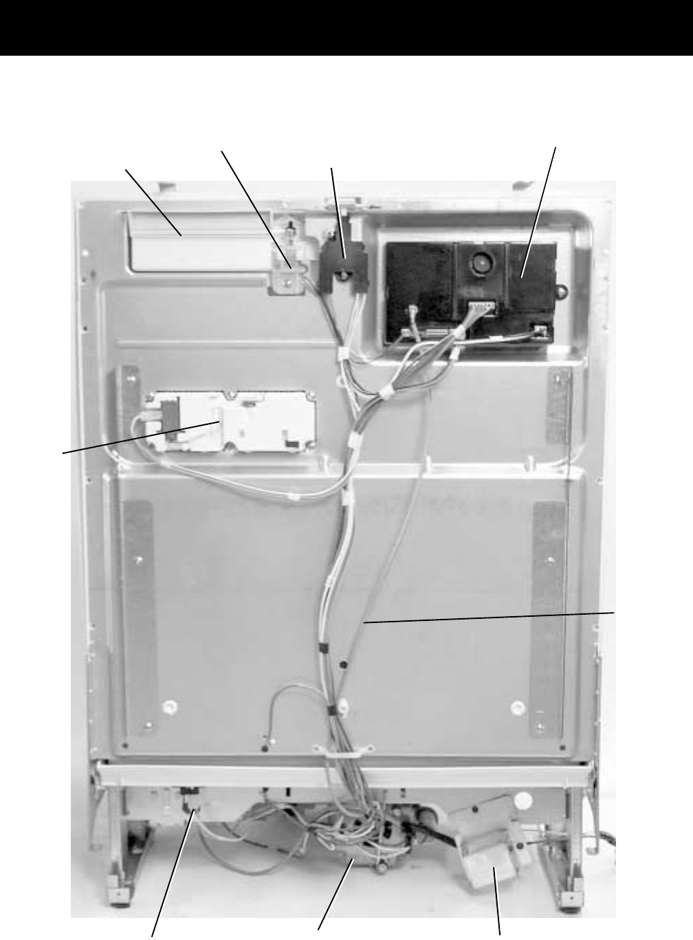
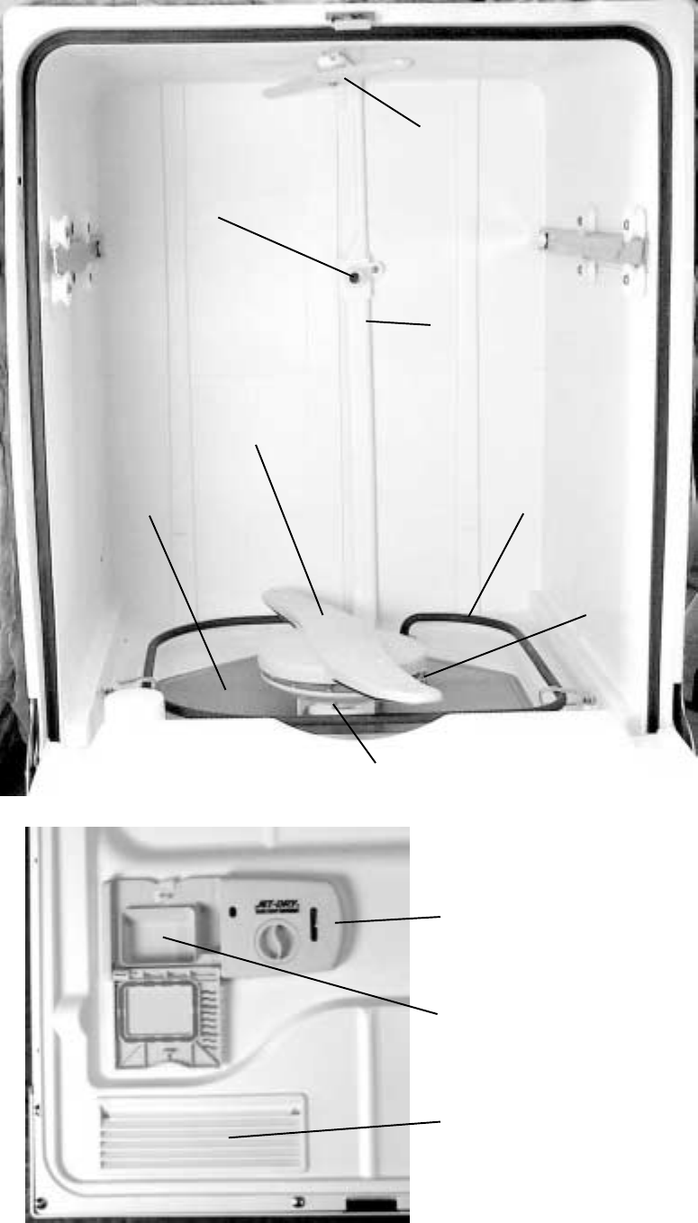
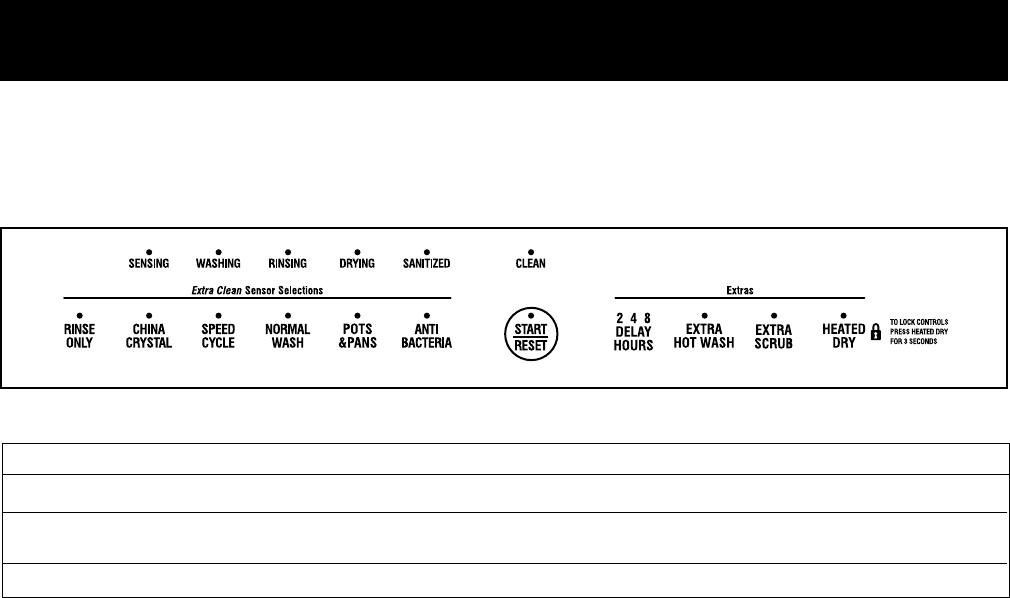
Component Locator Views
Door View (Panel and Escutcheon Removed)
Control Module
Flapper
(Active Vent)
House Electrical Supply
Junction Box
Factory Test
Cable
Detergent/
Rinse Agent
Module
Door Interlock
Switch
Vent Driver
(Active Vent)
Flood Switch Circulation Pump
– 10 –
Flood Switch Circulation Pump
Motor Junction Box
Turbitity
Sensor
Sump
High Drain Loop
Drain Pump
Drain Line
Check Valve
Water Valve
Bottom View
Factory
Test Cable
Connector
Heating
Element
Retaining
Nuts
Escutcheon Keypad
Assembly
Active Vent Latch Handle Control Module
Door View
(Front Panel ONLY Removed)
FRONT
BACK
FRONT
BACK
– 11 –
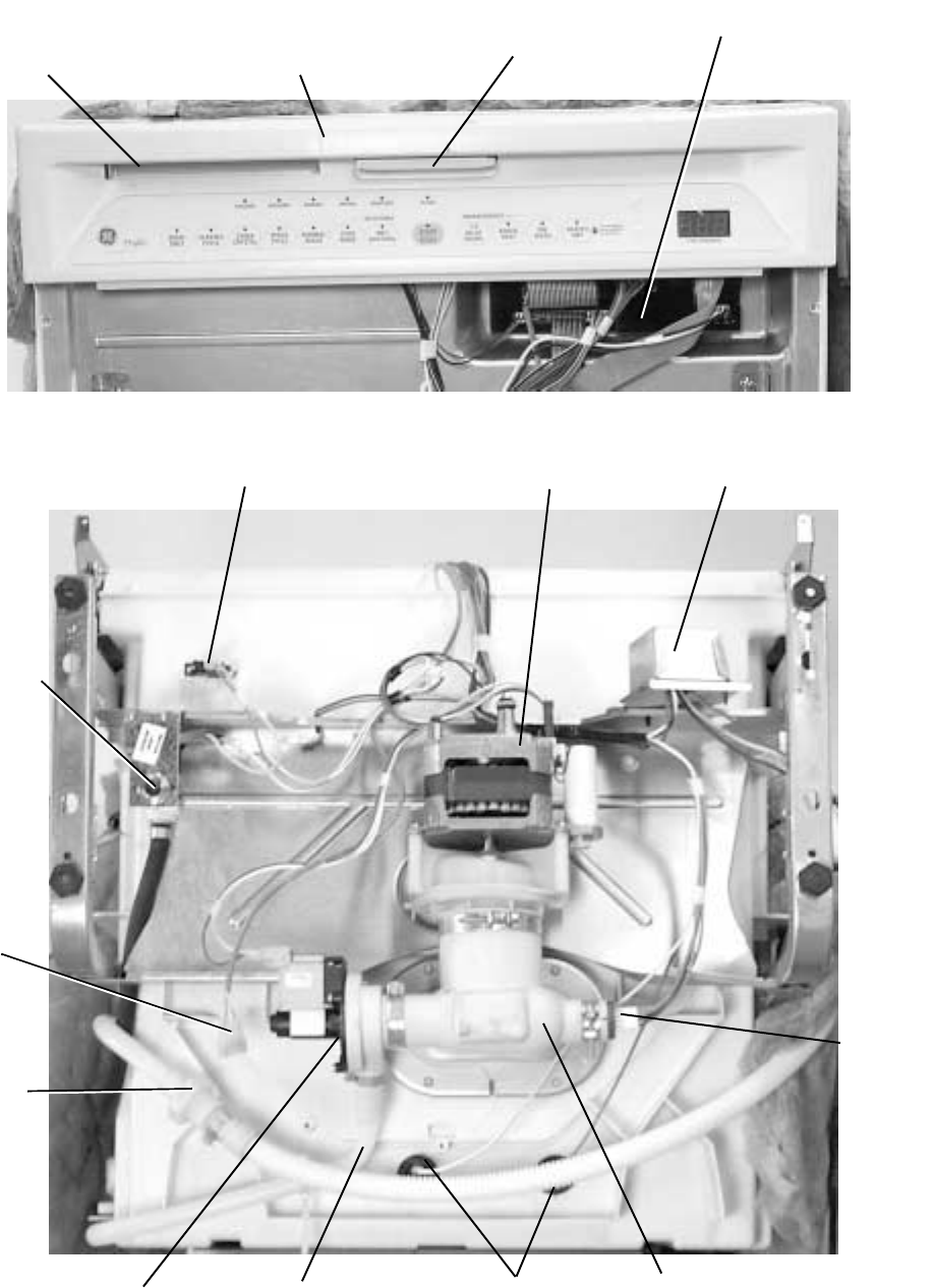
P0003687
Inside View
Inside
Door
View
Upper
Spray
Arm
Main Conduit
Heating Element
Fine Filter
Lower Spray
Arm
Inlet Cover
Hub
Detergent/Rinse
Module
Detergent
Compartment
Vent
(Active Vent)
Middle Spray Arm
Water Supply Connection
– 12 –
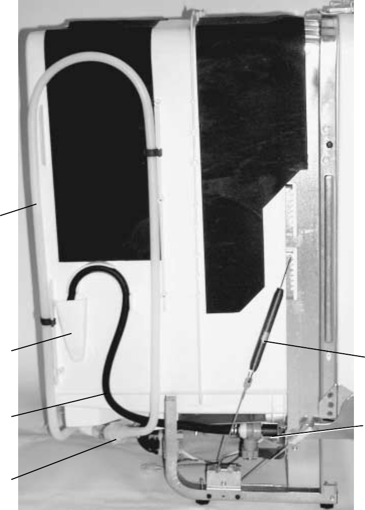
P0003689
Side View
Water
Valve
Drain Line
Check Valve
Fill
Funnel
Fill
Hose
Door
Spring
Drain Tube
Assembly
– 13 –
Dishwasher Components
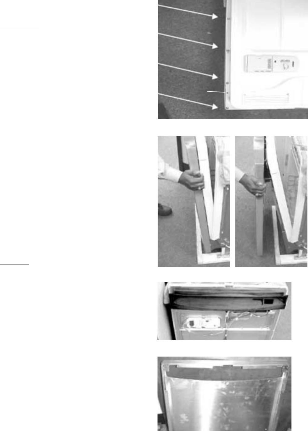
Door Components
The door components are accessible by removing
3 Phillips screws from each side of inner door and
2 T20 torx screws from the bottom of the door.
Carefully separate the inner door panel from the
outer door panel. To access the active vent,
flapper, and door interlock switch, the escutcheon
keypad assembly must be removed.
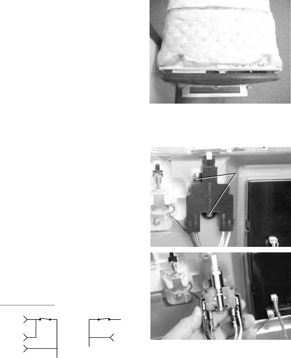
Escutcheon Keypad Assembly
The keypad and 2 ribbon cables are a permanent
part of the escutcheon and are replaced as a unit.
Disassembly
Caution: After removing the screws from the
escutcheon keypad assembly, the assembly is
still attached to the control module by 2 ribbon
cables. Dropping or rough handling of the
escutcheon will cause the ribbon cable to tear, and
the entire escutcheon keypad assembly will need
to be replaced.
1. Remove the outer door panel (see
Door Compo-
nents
).
2. Open the door, support the escutcheon
keypad assembly, and remove 6 screws from
the back side of the escutcheon keypad assem-
bly.
3. Remove the 2 ribbon cable connectors from the
control module and remove the escutcheon
keypad assembly.
Assembly
IMPORTANT: When reassembling, the active vent
flapper must be closed before the escutcheon
keypad assembly is installed. Close the active vent
flapper by turning the worm gear by hand. Failure
to do so will cause a misalignment and an
increase in noise level.
1. While supporting the escutcheon keypad as-
sembly, connect the 2 ribbon cable connectors
to the control module.
2. Open the door. Align the escutcheon and install
6 screws from the back side of the escutcheon
keypad assembly.
3. Install the outer door panel (see
Door Compo-
nents
).
Harness
Detergent
Module
Interlock
Switch
Assembly
Electronic
Control
Active Vent
Flapper
Figure 5
Control Module
Escutcheon Keypad Assembly
Active Vent
Worm Gear
Active Vent
Worm Gear
– 14 –
Control Module
Removal
1. Remove the outer door panel (see
Door Compo-
nents
).
2. Open the door and remove the 3 screws from
the back on the right side of the escutcheon
keypad assembly.
3. Remove 1 screw from the right side of the
control module and slide the module out.
4. Unplug the connectors from the module.
Installation
Note: The gray cable is a factory test cable (see
photo) and may be removed when servicing
control module.
1. Plug connectors into control module.
2. Insert the tabs on the left side of the control
module into the slots on the inner door panel
and secure the module with 1 screw.
3. Install 3 screws on the right side of the escutch-
eon and replace the outer door panel (see
Door
Components
).
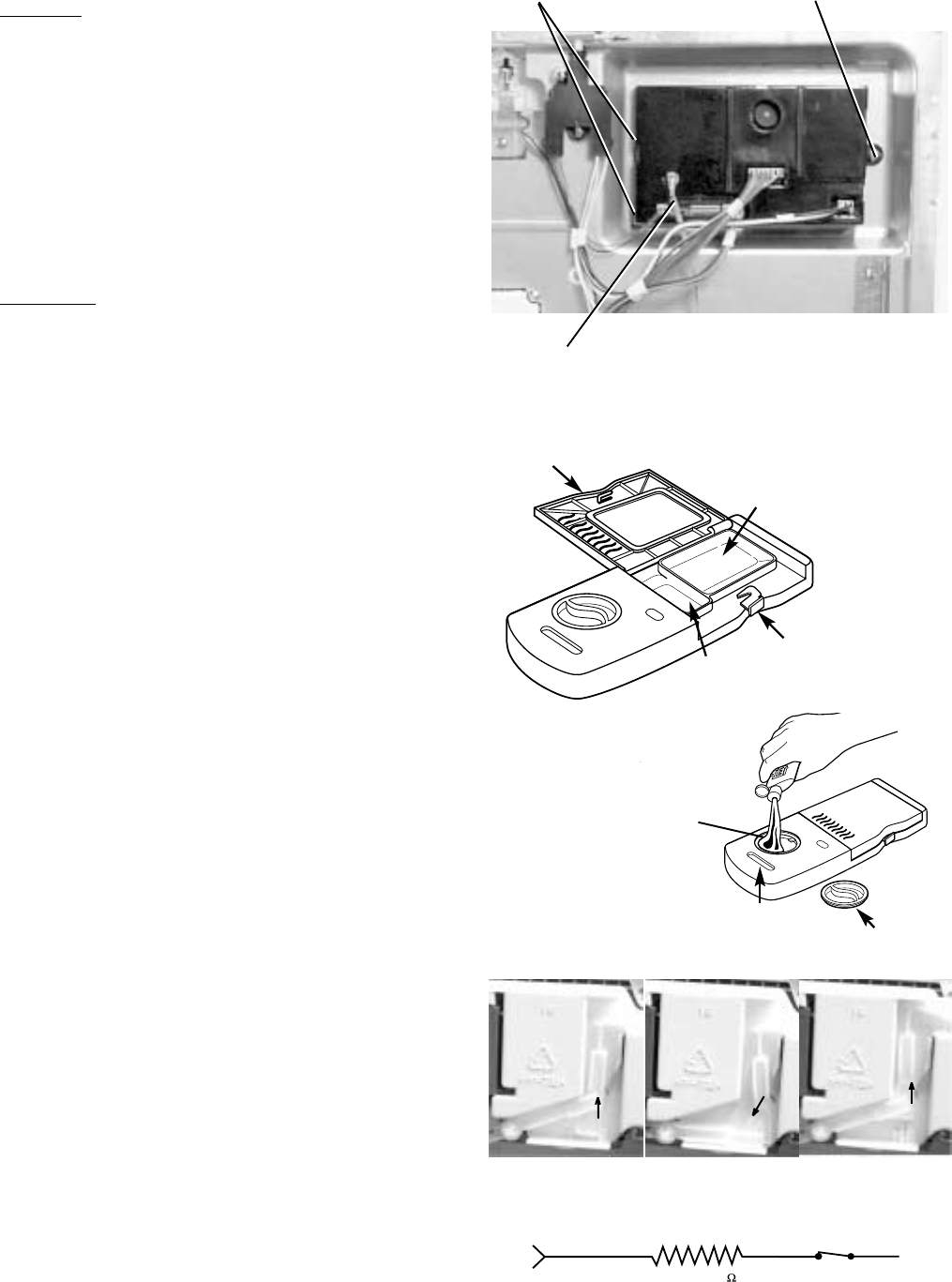
Detergent/Rinse Module
The door panel must be removed to access the
detergent/rinse module. Refer to the
Door Compo-
nent
section.
The detergent/rinse module can be activated using
service mode. Refer to the
Service Mode
chapter.
The detergent/rinse module automatically dis-
penses both the detergent and the rinse agent at
the appropriate times. The module is activated 2
times during a wash cycle.
The first time the module is activated (1), the lever
slides up the right-hand path of the connecting rod.
This action releases the detergent cover. When
deactivated (2), the lever returns down the left-
hand path and comes to rest under the notch in
the center of the connecting rod. At the second
activation (3), the lever lifts the connecting rod by
the notch. This action lifts the rinse dispenser
plunger and releases the rinse agent. When
deactivated, the lever returns to its original starting
position.
Cover
latch
Pre-wash
section
Main
wash
section
Cover
Indicator
window Dispenser cap
Rinse
agent
adjuster
P0003697
1 Screw
2 Tabs
Factory
Test Cable
123
L1 Voltage from J2-6
J2-6 RY WR
1200-2800
DETERGENT MODULE
NO
N
COM
WX
DOOR
INTERLOCK
– 15 –
Stainless Steel Bowed Panel
(On Some Models)
Disassembly
1. Open the dishwasher door to the fully open (89
degrees open) position.
2. Remove 8 screws (4 screws per side) which
hold the outer panel to the door assembly. Be
careful not to remove the 2 screws which hold
the escutcheon to the door assembly.
3. Slowly close the door.
4. Once the door is closed, remove the 2 screws
that connect the bottom of the outer panel to the
hinge arms.
5. While holding the outer panel against the door
assembly, slowly open the door to about 15
degrees open so the top of the outer panel is in
front of the kitchen countertop. If the dish-
washer is not installed, the door does not have
to be opened.
6. Rotate the bottom of the outer panel out such
that the panel is now vertical.
7. Lift up on the stainless steel outer panel such
that top corner flanges lift up over the corner
cutouts in the escutcheon. Move the panel
forward and over the escutcheon so that the
panel is totally separated from the door. (See
photos of escutcheon and outer panel below.)
Assembly
1. Open the door to about 15 degrees open so that
the top of the outer panel is in front of the
kitchen countertop. If the dishwasher is not
installed, the door does not have to be opened.
2. Lift the outer panel up in the vertical position and
hang the outer panel over top of the escutcheon.
Take care to ensure that the stainless steel
panel corner flanges go over and around the
escutcheon corner cutouts.
3. While holding the outer panel to the escutcheon,
slowly close the door.
4. With the panel hanging over the escutcheon,
rotate the bottom of the stainless steel outer
panel back so it is flush with the door assembly.
Make sure that the sides of the outer panel fit
around the hinge arms.
5. Look at the fit between the escutcheon and the
stainless steel outer panel front opening. Make
Do not remove
this screw from
either side.
– 16 –
sure that the protruding ribs from the escutch-
eon fit inside the stainless steel front opening.
Adjust the position of the outer panel up or
down, left or right to center the panel with the
escutcheon.
6. Once the panel is centered, install the 2 screws
in the bottom of the panel to connect the stain-
less steel outer panel to the hinge arms. Re-
check to make sure the escutcheon ribs are
protruding through the panel opening.
7. While holding the outer panel against the door
assembly, slowly open the door to about 45
degrees open so that the remaining 8 panel
screws can be installed (4 screws on each
side).
Door Interlock Switch
The door interlock switch opens the L1 circuit and
Neutral circuit when the door is open.
Caution: After removing the screws from the
escutcheon keypad assembly, the assembly is
still attached to the control module by 2 ribbon
cables. Dropping or rough handling of the
escutcheon will cause the ribbon cable to tear, and
the entire escutcheon keypad assembly will need
to be replaced.
1. Remove the escutcheon keypad assembly (see
Escutcheon Keypad Assembly
).
2. Remove 2 screws and the switch from the door.
3. Carefully remove the cover from the switch and
unplug the blade connectors.
Note: The wire color code is on the switch cover.
P0003703
2 Screws
2 Screws
P0003705
BXBW
BW
BX
NO COM
J2-7
J2-8
J1-3
J1-1
NO
N
L1
COM
WX DOOR WR
DOOR
DOOR INTERLOCK SWITCH
– 17 –
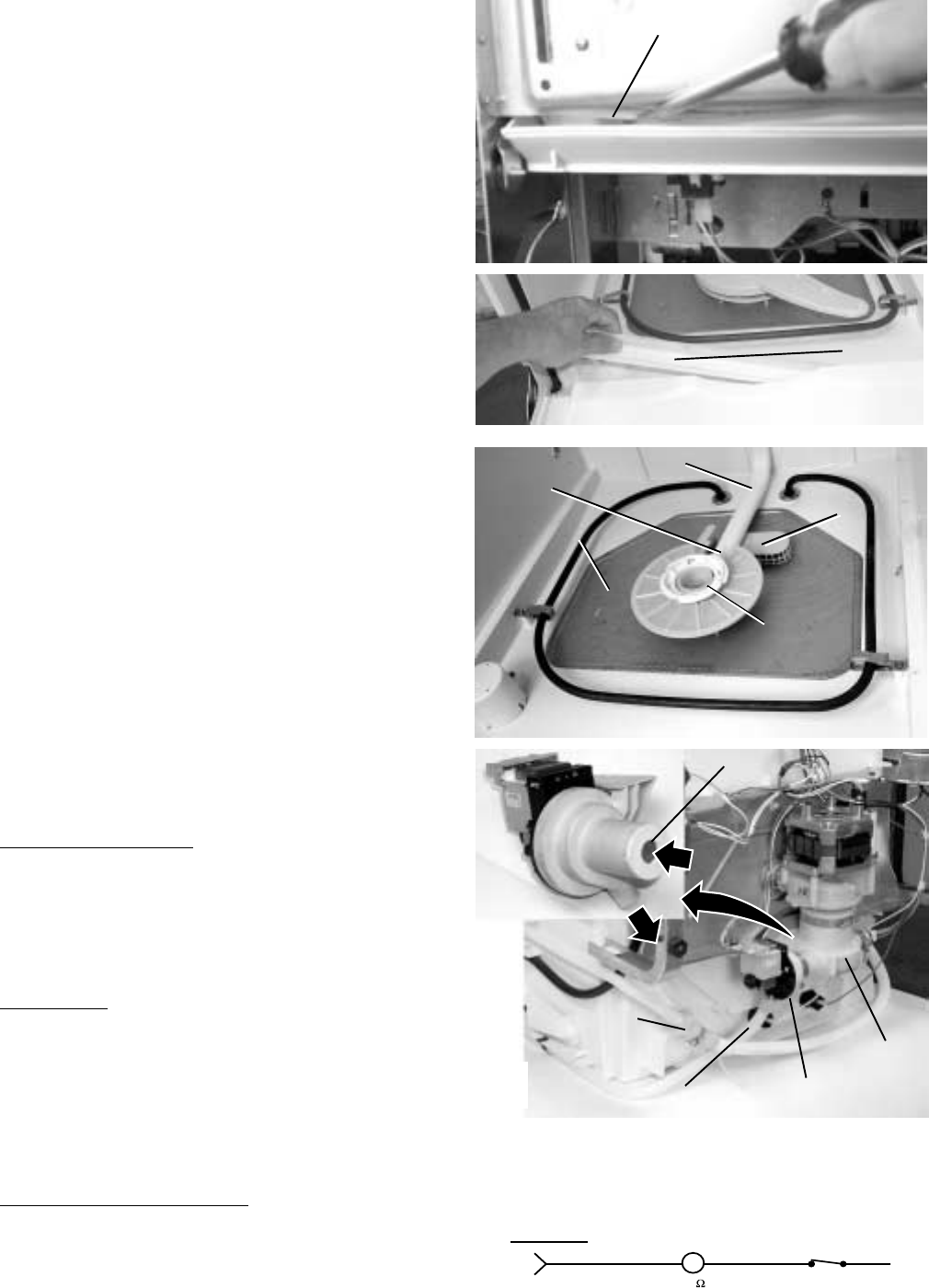
Bottom Door Seal
The bottom door seal is replaceable by removing
the outer door panel (see
Door Components
). With
the door closed, insert a flat-blade screwdriver
under the bottom of the door into the channel and
twist to break the bead. Open the door and pull the
seal from the channel. To install the seal, snap the
seal into the channel, working from one side of the
door to the other, until the entire bead is complete
and the seal slides freely in the channel.
Drain System
The drain system consists of the following
components:
•Inlet cover
•Sump
•Drain pump (includes motor and one-way check
valve)
•Drain pipe
•Check valve (in line with drain pipe)
The inlet cover prevents large particles from
entering the sump. Water entering the drain pump
is not filtered by the fine filter (metal) or by the
sump filter (plastic). The drain pump is mounted
on the sump and contains a one-way check valve.
The drain pump is controlled by the control module
and can be activated using service mode (refer to
the
Service Mode
chapter). The drain pump
pushes the drain water out into the drainpipe. The
drainpipe contains a one-way check valve.
Inlet Cover and Sump
Caution: Use care to avoid breaking the clip on
the hub when removing the main conduit from hub.
Remove the lower wash arm and main conduit to
gain access to the inlet cover and sump.
Drain Pump
The dishwasher must be removed from its instal-
lation to gain access to the drain pump. The drain
pump can be activated using service mode (refer
to the
Service Mode
chapter). The drain pump
contains a one way check valve. Refer to sche-
matic or strip circuit for motor resistance value.
Drain Pipe and Check Valve
The dishwasher must be removed from its instal-
lation to gain access to the check valve that is in-
line with the drainpipe.
Bottom
Door
Seal
Bottom Door Seal
Clip Main Conduit
Hub
Fine Filter
Inlet Cover
(sump filter is
under inlet cover)
Inlet Cover
(sump filter is
under inlet cover)
INLET
Drain Pump
OUTLET
One Way
Check Valve
Sump
Drain Pump
Drainpipe
Check Valve
(in-Line)
DRAIN PUMP
J2-5
M
RX WR
30 NO
N
COM
WX
DOOR
INTERLOCK
L1 Output from J2-5
– 18 –
Check for clogged:
inlet cover
sump
drain pump
drain pipe
one-way check valve
(in drain pipe)
YES NO
Check for open circuit between
control module and pump or
between pump and door interlock
switch. If circuits OK, replace
control module.
NO
Check pump for open/
shorted motor winding or
for stalled/clogged
condition.
YES
Attempt
to activate drain
pump using service mode
(refer to Service Mode
chapter).
Pump activate?
Is L1
voltage
present at pump?
Note: Perform this test
with wiring connected
and
pump under
load.
Circulation System
The circulation system consists of the following
components:
•Inlet Cover
•Fine filter and sump filter
•Sump
•Circulation pump
•Hub
•Lower spray arm
•Main conduit
•Middle spray arm
•Upper Spray arm
The inlet cover prevents large particles from
entering the sump. The fine filter (metal) and
sump filter (plastic) prevent fine particles from
entering the circulation-pump part of the sump
(water entering the drain pump is not filtered by the
fine filter or by the sump filter). The circulation
pump is controlled by the control module and can
be activated using service mode (refer to
Service
Mode
chapter). The pump pushes water up
Dishwasher Doesn’t Drain
Circulation
Pump
DRAIN PUMP
J2-5
M
RX WR
30 NO
N
COM
WX
DOOR
INTERLOCK
L1 Output from J2-5
Sump
Clip Main Conduit
Hub
Fine Filter
Inlet Cover
(sump filter is
under inlet cover)
Inlet Cover
(sump filter is
under inlet cover)
– 19 –
through the hub to the lower spray arm and to the
main conduit. The main conduit supplies water to
the middle and upper spray arms.
Inlet Cover
Caution: Use care to avoid breaking the clip on
the hub when removing the main conduit from hub.
Remove the lower wash arm and main conduit to
gain access to the inlet cover and sump.
Fine Filter, Sump Filter, and Sump
The dishwasher must be removed from its instal-
lation to gain access to the sump. The sump
must be removed to allow removal of the fine filter
and sump filter.
Circulation Pump
Note: It is extremely important that the self-tapping
ground-wire screw on the circulation pump is
tightened securely.
The dishwasher must be removed from its instal-
lation to gain access to the circulation pump. The
circulation pump can be activated using service
mode (refer to the
Service Mode
chapter). Refer to
schematic or strip circuit for motor resistance
value.
Lower Wash Arm
Lift and rotate (ccw) the lower spray arm to re-
move it from the hub. Clean the screen on the
water return if necessary.
Middle Wash Arm
Refer to illustration for disassembly.
Upper Wash Arm
Remove screw, plastic bearing, and upper wash
arm.
Conduit Carrier
Hub
Middle
Spray
Arm
Mid
Bracket
Nut
Bearing
Upper Rack
Tab
Mid Conduit
Screw
(Optional)
y arm for bits of
her foreign
or rotation.
-Level
CIRCULATION PUMP
J2-1
M
WR
NX
10
NO COM
WX
DOOR
INTERLOCK
N
L1 Output from J2-1
– 20 –
O-ring
Rotate clockwise 1/4 turn to remove.
Fill Funnel
The fill funnel is removable with a quarter turn
clockwise. There is an O-ring seal between the fill
funnel and the dishwasher tub.
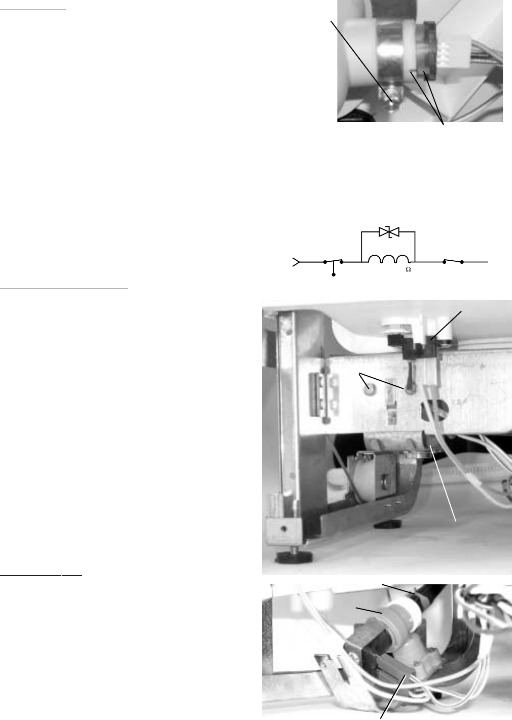
Calrod® Heating Element
The heating element can be activated using
service mode. Refer to the
Service Mode
chapter.
The dual wattage Calrod® heating element draws
835 W when it is wet to heat the water faster and,
No Water Circulation
CIRCULATION PUMP
J2-1
M
WR
NX
10
NO COM
WX
DOOR
INTERLOCK
N
L1 Output from J2-1
Check for clogged:
hub (remove lower wash arm)
inlet cover
fine filter
sump/sump filter
YES NO
Check for an open
circuit between control
module and pump or
between pump and door
interlock switch. If
circuits OK, replace
control module.
NO
Check pump for open/
shorted motor winding. YES
Pump is stalled/clogged.
Disconnect power and
attempt to turn pump using
cooling fins.
Motor capacitor is open/
shorted.
YES
Attempt
to activate
circulation pump using
service mode (refer to Service
Mode chapter).
Does pump
activate?
Does
the pump
hum?
Important:
Self tapping
ground-wire screw
on pump must be tightened
securely.
Is L1 voltage present at pump?
Note: Perform test with
wiring connected and
pump under
load.
NO
– 21 –
during the drying cycle, drops to 700 W for gentler
drying.
Water inlet temperature must be at least 120 °F for
proper drying. Low water inlet temperature will
prevent proper convection air movement and
increase drying time substantially.
If the complaint is the dishes are not drying cor-
rectly, don’t overlook the rinse agent. A rinse agent
will improve the water sheeting action and drying
performance.
Replacement
Note: The heating element nuts are located on the
underside of the washer, near the back. Ample
force is required to remove the nuts. Removing the
dishwasher from installation may be required.
1. Disconnect power and remove wire leads from
heating element.
2. Unscrew 2 heating element nuts.
3. Remove 2 screws, 2 heating element supports,
and the heating element.
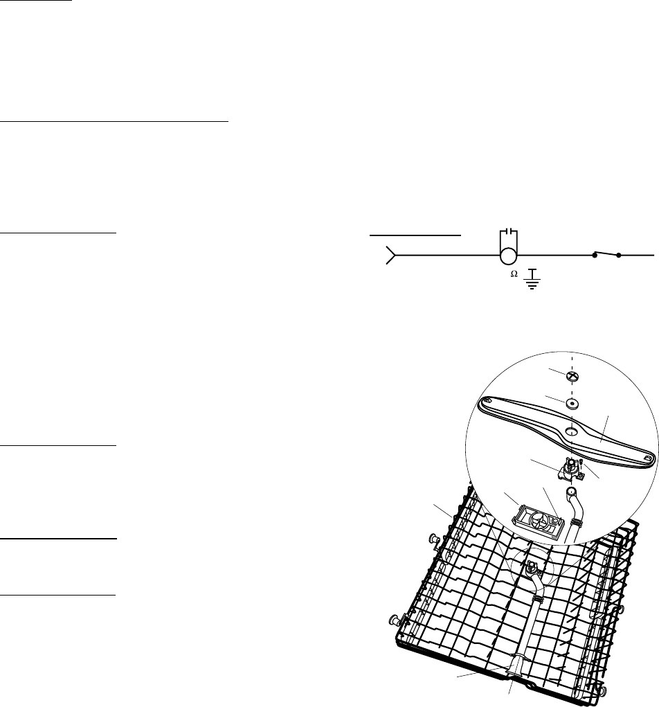
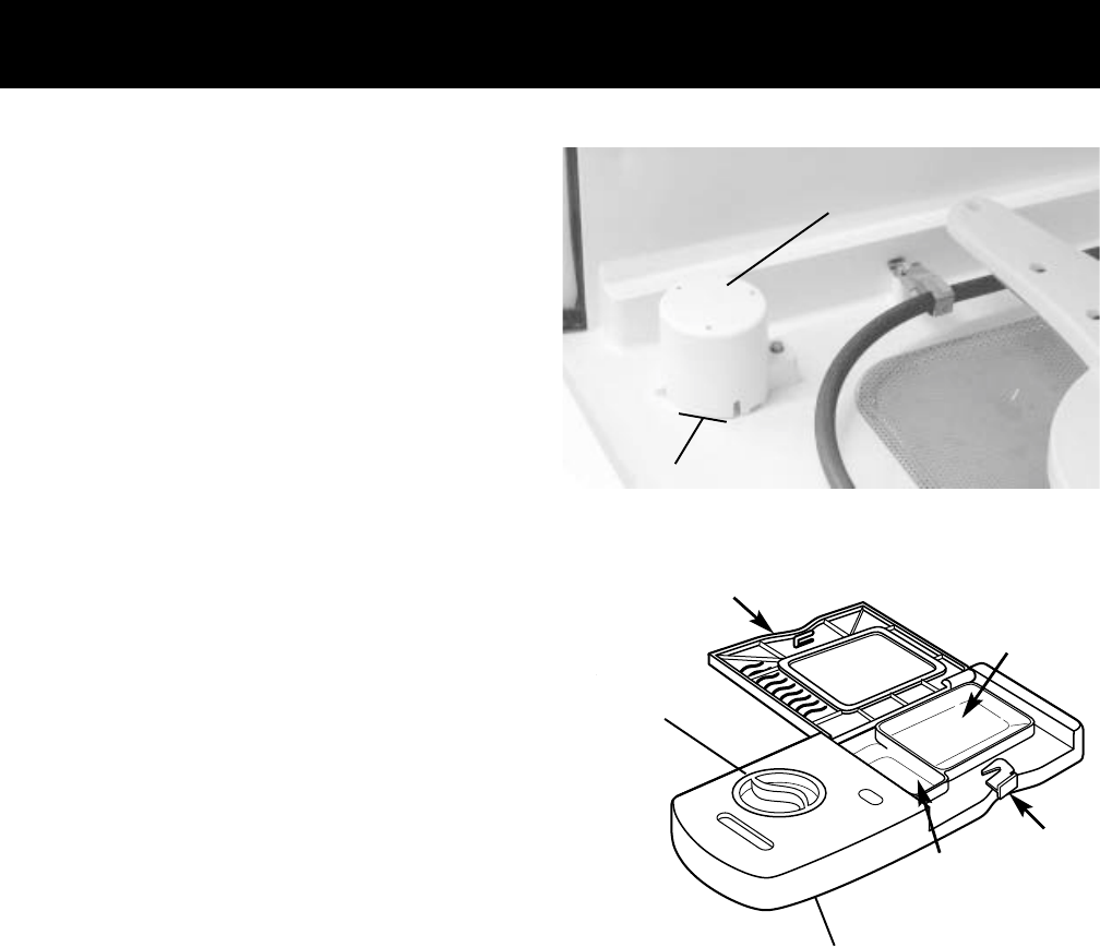
Turbidity Sensor
The turbidity sensor measures the amount of
suspended particles in the wash water in the sump.
As the sump water lays between the 1/4- to 3/8-
inch gap between the LED transmitter and the
receptor during the first fill, the baseline reading is
taken. Successive turbidity measurements are
supplied to the control module and used to deter-
mine whether any prewash or rinse cycles can be
skipped. Decisions are based on a comparison of
clean water measurements at the beginning of the
first fill, measurements taken at selected fills, and
water temperature. By measuring the turbidity level,
the control module can conserve energy on lightly
soiled loads by skipping unnecessary cycles.
Note: If the turbidity sensor circuit fails open or
shorted, the sensing LED on the control panel will
not light and the unit will operate for the maximum
amount of time, using the maximum number of
wash and rinse fills for the selected cycle.
The turbidity sensor also contains the thermisteor
for automatic temperature control.
Turbidity Sensor Test
Factory test mode is the most accurate way to test
the turbidity sensor circuit (circuit contains control
module, wiring, and turbidity sensor). Refer to the
Factory Test Mode
chapter.
Figure 4
Tub
Nut
Heating Element
Support
Heating
Element
Heater
Grommet
Heating
Element Nuts
(Bottom View)
Turbidity Sensor
Turbidity Sensor
HEATING ELEMENT
J2-3
J2-4
VX
HEATING ELEMENT
19.4-19.8 NO
N
COM
WX
DOOR
INTERLOCK
WR
1
2
3
4
GY
NX
SX
OX
NTC
TURBIDITY SENSOR
Refer to
Wiring Diagram
for voltages and pin-outs.
– 22 –
NONO
N
COM
WX
DOOR
INTERLOCK
WR
PX YX
FLOOD
SWITCH
C
WATER VALVE
725-1200
J2-2
WATER VALVE AND
FLOOD SWITCH
L1 voltage from J2-2
Water Valve and Flood Switch
The water valve is a 120 VAC (L1) solenoid valve
that is switched on/off by the control module. The
flood switch acts as a safety switch only and does
not control normal operation of the water valve.
The flood switch opens the L1 side of the water
valve circuit.
Water Valve Replacement
The water valve can be replaced with the dish-
washer installed.
WARNING: Disconnect power to dishwasher
before proceeding.
1. Turn off water supply to dishwasher.
2. Remove toekick.
3. Disconnect house plumbing from dishwasher.
4. Remove 2 screws and valve from dishwasher
frame.
5. Disconnect connector.
6. Move clamp up, away from valve, and remove
valve from hose.
Note: To prevent leaks after installation, ensure
that hose-to-valve connection is good and that
clamp is in place.
Water Valve Test
1. Attempt to activate water valve using service
mode (see
Service Mode
chapter). Pump out
water as necessary using service mode. If an
intermittent failure is suspected, activate water
valve 5 times using service mode. Water valve
should stay on for 50 - 71 seconds per activa-
tion and should not turn on and off during the
50 - 71 second activation time.
2. If the water valve is not operating properly or
Flood Switch
Screws
Water Valve
Clamp
Water Valve
Connector
Replacement
To remove the turbidity sensor from the side of the
sump, loosen the screw and slide the retaining
clamp back. Remove turbidity sensor from the
sump and unplug connector from the turbidity
sensor.
Note: When installing the turbidity sensor, align
the key on the sensor with the keyway on the
sump. Keyway and Key
Screw
Screw
Turbidity
sensor
shown
partially
removed.
– 23 –
Flapper
Vent Drive
ACTIVE VENT
+ or – 12 VDC at J5-1
+ or – 12 VDC at J5-2
M
ACTIVE
VENT
MOTOR
BX
RX
J5-1
J5-2
water level is low, check the following:
• Flood switch, flood switch float, and float stem
- Flood switch should open when water level is
approximately 1/4 in. above the base (bottom)
of the float dome.
• Resistance through the water valve solenoid
coil - Check from yellow wire at flood switch to
white/red wire at door interlock switch (Es-
cutcheon keypad assembly must be removed,
refer to
Escutcheon Keypad Assembly
section).
• Clogged screen in water valve.
Caution: After removing the screws from the
escutcheon keypad assembly, the assembly is
still attached to the control module by 2 ribbon
cables. Dropping or rough handling of the
escutcheon will cause the ribbon cable to tear, and
the entire escutcheon keypad assembly will need
to be replaced.
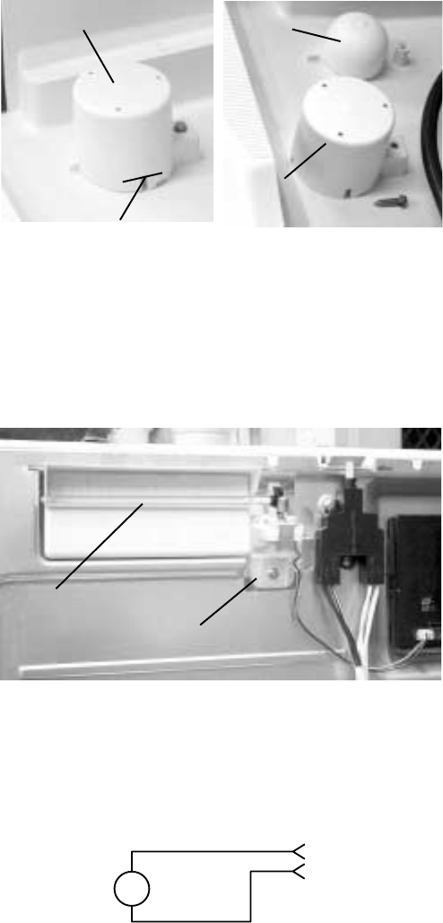
Active Vent
The active vent helps to reduce the noise level and
heat loss when in the closed position. The control
module supplies +/- 12 VDC to the motor. The
control module reverses polarity to drive the motor
in a clockwise or counterclockwise (open or
closed) direction. The vent is closed during the
wash cycle and open during the drying cycle
(heated and non-heated) and when the unit is not
in use. If the vent is closed and the door is opened
during the wash cycle, the vent will open. When
the door is closed again, the vent will remain open
for seven (7) seconds, then close again to finish
the cycle.
It is normal for steam to come through the active
vent during the dry cycle.
The active vent can be opened and closed using
the service mode. Refer to the
Service Mode
chapter.
The active vent can be accessed by removing the
escutcheon keypad assembly (see
Escutcheon
Keypad Assembly
section).
IMPORTANT: When reassembling, the active vent
flapper must be closed before the escutcheon
keypad assembly is installed. Close the active vent
flapper by turning the worm gear by hand. Failure
to do so will cause a misalignment and an
increase in noise level.
Float Dome
Water Level
Float Dome
(removed)
Float
– 24 –
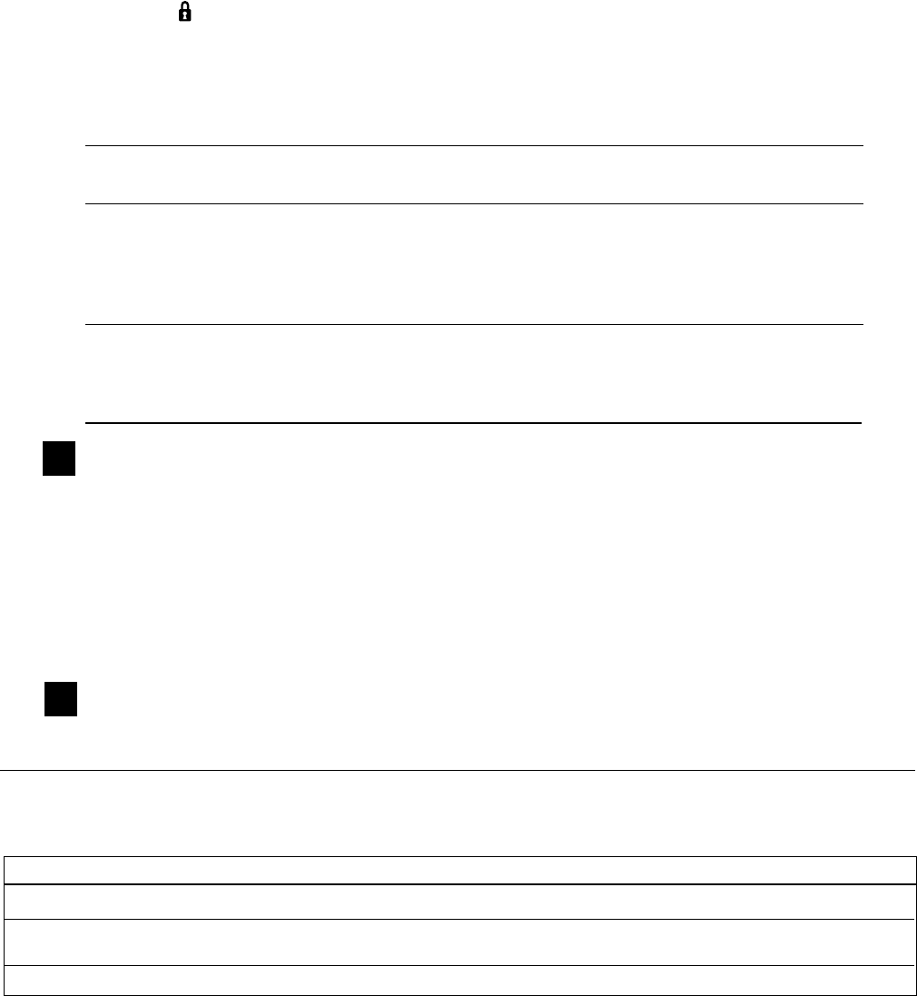
Flashing Display Lights
The status display tells you what’s happening while the dishwasher is in operation and may flash, indicat-
ing a malfunction. The lights will come on indicating the sequence of operation the dishwasher is in.
FLASHING DISPLAY LIGHTS
Status Indicator Lights What It Means
START/RESET
Cycle has been interrupted by pressing the
START/RESET
keypad. Light will quit
flashing after the dishwasher automatically drains out the water.
CLEAN
Unit has no water. Check the water supply. If water is turned on call for service.
– 25 –
Service Mode
THIS DISHWASHER IS PROGRAMMED WITH A SERVICE MODE TO AID THE TECHNICIAN IN TROUBLESHOOTING THE DISH-
WASHER. EACH COMPONENT MAY BE CYCLED TO DETECT IF IT IS FUNCTIONING CORRECTLY. COMPONENTS ARE CYCLED BY
PRESSING KEYPADS TO THE RIGHT OR LEFT OF THE START/RESET KEYPAD. DETERMINE WHICH TYPE OF CONTROL PANEL IS
PRESENT (FLAT OR BOWED) AND THEN USE THE MATRIX BELOW TO DETERMINE HOW TO CYCLE EACH COMPONENT.
FLAT PANEL BOWED PANEL
TO ENTER SERVICE MODE :
PRESS THE COOKWARE (POTS & PANS ON SOME MODELS)
AND THE HEATED DRY KEYPAD SIMULTANEOUSLY FOR 3
SECONDS.
TO EXIT SERVICE MODE :
PRESS THE START/RESET KEYPAD AT ANYTIME TIME TO EXIT.
*NOTE : Service mode may
be used for 30 minutes
maximum. After 30 minutes
the service mode will
automatically turn off.
**NOTE : Component will be
activated for indicated
time. Component may be
deactivated by pressing
the same keypad that was
pressed to activate the
component.
TRITON XL SERVICE MODE TEST MATRIX *
KEYPAD
CONTROL DESCRIPTION TIME in seconds**
PAD TYPE
Keypads to the left of the Start/Reset keypad (Selections)
FLAT Activates Drain Pump
1L BOWED Activates Detergent Module 75
FLAT Activates Detergent Module
2L BOWED Activates Main Pump 60
FLAT Activates Main Pump
3L BOWED Activates Heating Element 75
FLAT Activates Heating Element
4L BOWED Activates Drain Pump 300
FLAT Activates Water Valve
5L BOWED
(Length of time is model dependent)
50 or 71
START/RESET Used to EXIT Service Mode
Keypads to the right of the Start/Reset keypad (Enhancement/Extras)
Activates the following in order:
Status LEDs; Wash LEDs;
1R FLAT Start/Reset and Option LEDs; 3 seconds each cycle
BOWED finally “888” will be shown
on the 3 digit display
(some models)
FLAT
2R BOWED Closes Active Vent
FLAT
3R BOWED Opens Active Vent
5L 3L 2L 1L
4L
START
RESET
1R 2R 3R 4R
Indicates Keypad Used Only on Some Models
4L
START
RESET
1L
2L
3L
5L 1R 2R 3R 4R
Indicates Keypad Used Only on Some Models
Opens Active Vent
Closes Active Vent
– 26 –
Factory Test Mode
Entering Factory Test Mode
Note: This mode can only be entered within the
first 2 minutes after power-up. After 2 minutes,
factory test mode is unavailable.
1. Disconnect power from dishwasher. Wait 10
seconds and connect power to dishwasher.
2. Press the NORMAL WASH keypad and POTS &
PANS (or COOK WARE) keypad at the same
time for 5 seconds (This step must be
performed within 2 minutes of power-up).
3. The following sequence should occur:
a. All LEDs illuminate for a short period of time.
b. Water valve activates. The dishwasher will fill
for the appropriate amount of time.
c. Circulation pump activates. The dishwasher
will circulate for approximately 1 minute.
d. Turbidity sensor check. The control module
will check the thermistor circuit, the turbidity
(transmitter) circuit, and calibrate itself to the
turbidity sensor (transmitter). The turbidity
sensor check lasts for 20 to 30 seconds.
• If the turbidity sensor check fails, the control
module will beep continuously and the Lock
LED will be illuminated. The control
module, wiring, and turbidity sensor are
suspect if the turbidity sensor check fails.
Press any keypad to stop the control
module beeping and move to the next step
in the factory test mode sequence.
• If the turbidity sensor check passes, the
control module will automatically move to
the next step in the factory test mode
sequence.
e. Drain pump activates. Allow the dishwasher
to pump out all water (approximately 75
seconds). After the water has been pumped
out, the dishwasher will begin to fill again.
Press the START/RESET keypad while the
dishwasher is filling. The dishwasher will then
pump out for approximately 2 minutes and
then return to normal operation. The
dishwasher will automatically exit factory test
mode 1 hour and 10 minutes after the test
was initiated if the START/RESET keypad is
not pressed to exit.
Factory test mode is the most accurate way to test the turbidity sensor circuit (circuit contains control
module, wiring, and turbidity sensor). Factory test mode will test the thermistor (used for Automatic
Temperature Control) that is contained in the turbidity sensor and will test the transmitter that is con-
tained in the turbidity sensor.
– 27 –
Washability Complaints
Hot Water – Ample supply of water at a minimum
temperature of 120 °F is necessary. Do not use
dishwasher soon after using clothes washer or
filling bath tub.
Loading – Consult Owner’s Manual on loading
procedures.
Amount of Water – Make sure dishwasher is
level. Check water level, allowing dishwasher to fill
normally for first fill. The water level should be
to the base (bottom) of the float dome. If water
level is low, check for clogged screen in water
valve and check flood switch. Refer to the
Water
Valve and Flood Switch
section.
Detergent/Rinse Module Leakage – Some
moisture in cup is normal. Detergent must not be
soaking wet, oozing out and down the inner door
panel. If a leak is detected, check the detergent/
rinse module door lid, latch operation, and gasket
seal. Also refer to the
Detergent/Rinse Module
section.
Proper Amount of Detergent – Use full detergent
cup of fresh detergent in hard water. Use only
enough detergent to get good wash performance
in soft water.
Rinse Agent – Use rinse agent if spotting or
drying is a problem. A rinse agent will improve the
water sheeting action and drying performance.
Water Valve – Refer to the
Water Valve and Flood
Switch
section.
Spray Arm – Check to be sure all 3 spray arms
spin freely and jets are not clogged. Check to be
sure the middle spray arm water conduit is con-
necting properly to the main conduit.
Drying – Water inlet temperature must be at least
120 °F for proper drying. Low water inlet tempera-
ture will prevent proper convection air movement
and increase drying time substantially.
A rinse agent will improve the water sheeting
action and drying performance.
Cover
latch
Pre-wash
section
Main
wash
section
Cover
Rinse
agent
Detergent/Rinse Module
Float Dome
Water Level
– 28 –
Cycle Progression Chart
* When maximum temperature is reached and the calrod is on the calrod will be cycled on and off.
**Heater is on for the first 6 minutes then cycles.
# The CLEAN NORMAL run will insert the pre-soak after 3 minutes into the first fill. The cycle will be a NORMAL with dirty water where the
first fill is 3 minutes, and the second and third fills are skipped.
SPEED GLASSES CHINA POTS & ANTI- RINSE
(CLEAN) (DIRTY) CYCLE CYCLE CRYSTAL PANS BACTERIA ONLY
fill time 49 / 70 sec 49 / 70 sec 50 / 71sec 50 / 71sec 50 / 71sec 50 / 71sec 50 / 71sec 50 / 71sec
fill quantity 1.4 gal 1.4 gal 1.43 gal 1.43 gal 1.43 gal 1.43 gal 1.43 gal 1.43 gal
detergent cupafter 3 minutes no no no no no no no
calrod after 3 minutes no yes yes yes yes yes no
cycle time 19 minutes 1 - 8 minutes1 - 2 minutes 1 - 2 minutes 1 minute 1 - 8 minutes 1 minute 1 minute
fill time 49 / 70 sec 49-50 / 70-71 50 / 71 sec 49-50 / 70-71 49-50 / 70-71 50 / 71 sec 50 / 71 sec 50 / 71 sec
fill quantity 1.4 gal 1.4 - 1.43 gal 1.43 gal 1.4 - 1.43 gal 1.4 - 1.43 gal 1.43 gal 1.43 gal 1.43 gal
detergent cup no no no no no no no no
calrod no no yes yes yes yes yes no
cycle time 5 minutes 1 - 8 minutes1 - 2 minutes 1 - 8 minutes 1 - 8 minutes 1 - 8 minutes 1 minute 1 minute
fill time 49 / 70 sec 49 / 70 50 / 71 sec 49-50 / 70-71 49-50 / 70-71 50 / 71 sec 50 / 71 sec -
fill quantity 1.4 gal 1.4 gal 1.43 gal 1.4 - 1.43 gal 1.4 - 1.43 gal 1.43 gal 1.43 gal -
detergent cup no no no no no no no -
calrod no no yes yes yes yes yes -
cycle time 5 minutes 1 - 8 minutes1 - 2 minutes 1 - 8 minutes 1 - 8 minutes 1 - 8 minutes 1 - 8 minutes -
fill time 49 / 70 sec - - - - 50 / 71 sec - -
fill quantity 1.4 gal - - - - 1.43 gal - -
detergent cupyes (rinse aid) - - - - no - -
calrod yes - - - - yes - -
cycle time 9 minutes - - - - 1 - 10 minutes - -
-
fill time
#
50 / 71 sec 50 / 71 sec 50 / 71 sec 50 / 71 sec 50 / 71 sec 50 / 71 sec 50 / 71 sec
fill quantity
#
1.43 gal 1.43 gal 1.43 gal 1.43 gal 1.43 gal 1.43 gal 1.43 gal
detergent cup
#
no no no no no no no
calrod
#
yes yes yes yes yes yes yes
cycle time
#
13 minutes 13 minutes 13 minutes 13 minutes 13 minutes 13 minutes 13 minutes
fill time - 49-50 / 70-71 50 / 71 sec 50 / 71 sec 50 / 71 sec 50 / 71 sec 50 / 71 sec -
fill quantity - 1.4 - 1.43 gal 1.43 gal 1.43 gal 1.43 gal 1.43 gal 1.43 gal -
detergent cup - yes yes yes yes yes yes -
calrod - yes yes yes yes yes yes -
cycle time - 15 - 30 minutes7 - 10 minutes 5 minutes 5 minutes 20 - 40 minutes 5 minutes -
- 130 F - - 110 F 140 F 130 F -
- 15 minutes - - 10 minutes 15 minutes 15 minutes -
fill time - 49 / 70 sec 50 / 71 sec 50 / 71 sec 50 / 71 sec 50 / 71 sec 50 / 71 sec -
fill quantity - 1.4 gal 1.43 gal 1.43 gal 1.43 gal 1.43 gal 1.43 gal -
detergent cup - no no no no no no -
calrod - no yes yes yes yes yes -
cycle time - 5 minutes 5 minutes 6 minutes 6 minutes 5 minutes 5 minutes -
fill time - 49 / 70 sec 50 / 71 sec 50 / 71 sec 50 / 71 sec 50 / 71 sec 50 / 71 sec -
fill quantity - 1.4 gal 1.43 gal 1.43 gal 1.43 gal 1.43 gal 1.43 gal -
detergent cup - no no no no no no -
calrod - no yes yes yes yes yes -
cycle time - 5 minutes 5 minutes 2 minutes 5 minutes 5 minutes 5 minutes -
-
fill time - 49 / 70 sec - 50 / 71 sec 50 / 71 sec 50 / 71 sec 50 / 71 sec -
fill quantity - 1.4 gal - 1.43 gal 1.43 gal 1.43 gal 1.43 gal -
rinse aid - yes - yes yes yes yes -
calrod - yes - yes yes yes yes -
cycle time - 9 minutes - 8 minutes 9 minutes 9 minutes 1 - 60 minutes -
NORMAL WASH
15 minutes cool
d
15 minutes dry** -
FIRST FILL
DRY
30 minutes** 30 minutes** 8 minutes** 30 minutes** 30 minutes** 30 minutes**
if temp not
reached, main
wash enters
extend time
second rinse
extended to 14
minutes
third rinse exten
25 minutes
SECOND RINSE
THIRD RINSE
FIRST RINSE
third rinse ex
t
to 25 minutes
HI-TEMP
OPTION
cycle time
MAX TEMP
M
W EXTEND
THIRD FILL
FOURTH FILL
MAIN WASH
POWER
PRE-SOAK
OPTION
160 °F* -
SECOND FILL
140 °F* 130 °F* 130 °F* 145 °F*140 °F* 140 °F*
no effect, third rinse
run time is determined
by sanitation
requirements
-
fourth fill extended
to 25 minutes
third rinse exte
n
22 minutes
third rinse exten
25 minutes
– 29 –
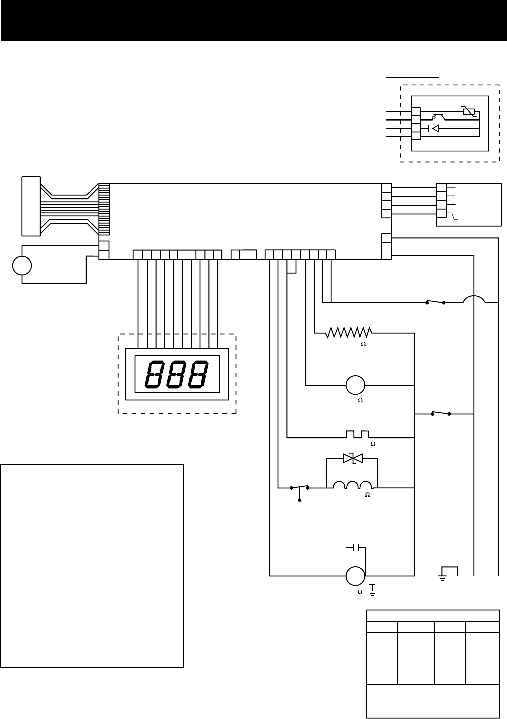
Wiring Diagram
WARNING: Power must be disconnected before servicing the appliance.
K
E
Y
P
A
D
CONTROL CIRCUIT BOARD
3-DIGIT DISPLAY
M
ACTIVE
VENT
MOTOR
BX
RX
J7
KEYPAD
12345678910 123 12345678
1
2
J5
ACTIVE
VENT
3-DIGIT DISPLAY
J8
PQA
J10
POWER SWITCHING
J2
1
2
3
1
2
3
4
TURBIDITY/
TEMPERATURE
SENSOR J3
---THIS CIRCUIT NOT IN
ALL MODELS
J1
POWER
SUPPLY
1
2
3
4
NTC
RECEIVER EMITTER
TRANSMITTER
CATHODE
Vcc
GY
NX
SX
OX
M
M
BW
NO COM
BX
DOOR
INTERLOCK
NO COM
WX
DOOR
INTERLOCK
WR
DETERGENT MODULE
RY WR
WR
WR
WR
NX WR
CIRCULATION
PUMP
GY
NL1
WX
BX
PX YX
FLOOD
SWITCH
CNO
WATER VALVE
725-1200
19.4-19.8
VX
HEATING ELEMENT
RX
DRAIN PUMP
1200-2800
G
10
COLOR CODE
LETTERS COLOR LETTERS COLOR
THE "X" INDICATES ONE SOLID COLOR- NO
TRACER. WIRES WITH TRACER SHOW
BOTH COLORS. EXAMPLE -WR IS WHITE
WITH RED TRACER.
AX
BX
CX
NX
OX
PX
LT. BLUE
BLACK
BROWN
DK. BLUE
ORANGE
PINK
RX
SX
TX
VX
WX
YX
RED
GRAY
TAN
PURPLE
WHITE
YELLOW
30
1
2
3
4
GY
NX
SX
OX
NTC
TURBIDITY SENSOR
COLOR CODE
LETTERS COLOR LETTERS COLOR
THE "X" INDICATES ONE SOLID COLOR- NO
TRACER. WIRES WITH TRACER SHOW
BOTH COLORS. EXAMPLE -WR IS WHITE
WITH RED TRACER.
AX
BX
CX
NX
OX
PX
LT. BLUE
BLACK
BROWN
DK. BLUE
ORANGE
PINK
RX
SX
TX
VX
WX
YX
RED
GRAY
TAN
PURPLE
WHITE
YELLOW
CONN. INPUT/OUTPUT COMPONENT
J1-1 Neutral House Supply
J1-3 L1 Input House Supply
J2-1 L1 Output Circ. Pump
J2-2 L1 Output Water Valve
J2-3 L1 Output Heating Elem.
J2-4 L1 Output Heating Elem.
J2-5 L1 Output Drain Pump
J2-6 L1 Output Det. Module
J2-7 L1 Input Door Interlock
J2-8 L1 Input Door Interlock
J3-1 Input (thermistor) Turbity Sensor
J3-2 Input (turbidity) Turbity Sensor
J3-3 0 to 5 VDC output* Turbity Sensor
J3-4 5 VDC output* Turbity Sensor
J5-1 + or - 12 VDC* Active Vent
J5-2 + or - 12 VDC* Active Vent
*Measure voltage with black test lead
connected to J10-1.
CONTROL MODULE
– 30 –
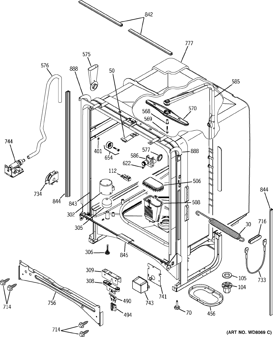
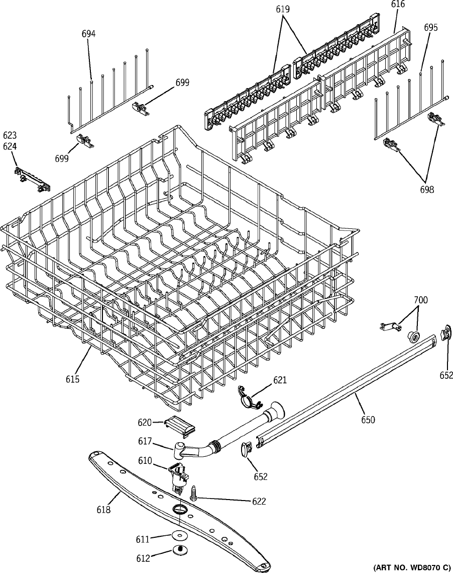
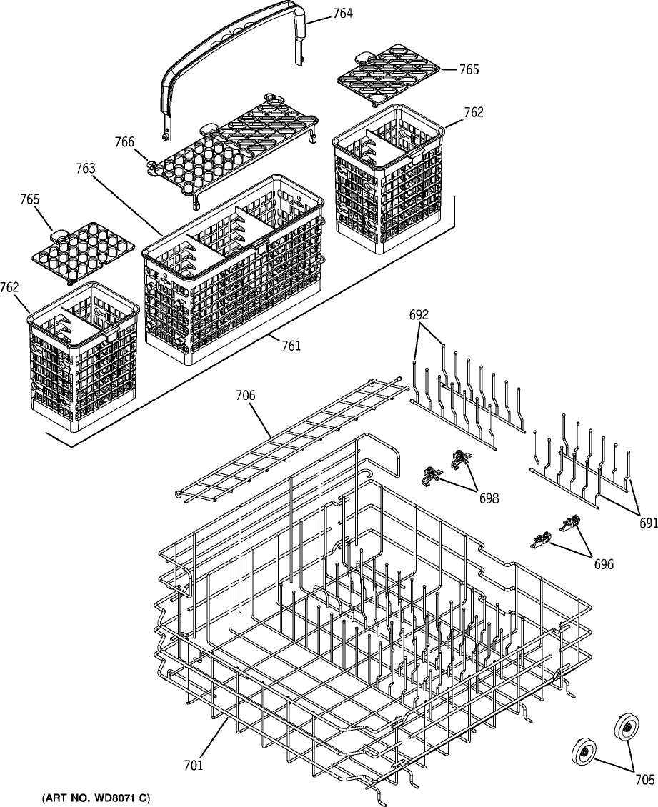
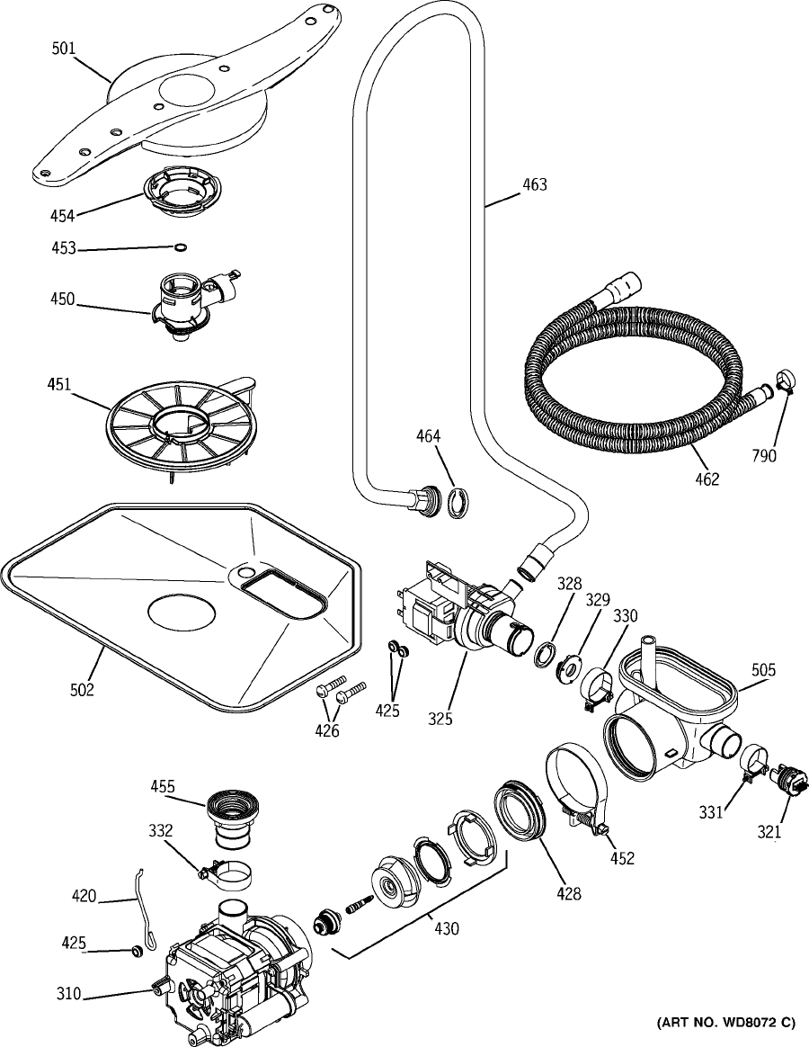
Parts List
Note: The components shown in this
drawing may differ from the components in
your unit. Refer to the microfiche or GEA
IPC for the component and part number
for your unit.
Door
– 31 –
Note: The components shown in this
drawing may differ from the components in
your unit. Refer to the microfiche or GEA
IPC for the component and part number
for your unit.
Body Parts
– 32 –
Note: The components shown in this
drawing may differ from the components in
your unit. Refer to the microfiche or GEA
IPC for the component and part number
for your unit.
Upper Rack
– 33 –
Note: The components shown in this
drawing may differ from the components in
your unit. Refer to the microfiche or GEA
IPC for the component and part number
for your unit.
Lower Rack
– 34 –
Note: The components shown in this
drawing may differ from the components in
your unit. Refer to the microfiche or GEA
IPC for the component and part number
for your unit.
Pumps and Filters

– 35 –
1 31-30365 PM SHEET MINI MANUAL 1
1 31-30530 PM INSTRUCTION INSTALL 1
1 49-5908 PM MANUAL USE & CARE 1
30 WD03X10014 SPRING 2
42 WZ4X376D SCR 10-16X3/4 #8 HX SSTL 3
50 WD13X10006 KEEPER LATCH ASM 1
51 WD02X10066 SCR 10-24X1/2 TT TRR S 1
70 WD02X0320 SCREW LEVEL 4
101 WD05X10005 ELEMENT HEATING ASM 1
104 WD01X10097 NUT TOWER HEATER 2
109 WD01X10094 GROMMET HEATER 2
112 WD01X10098 SUPPORT HEATER 2
302 WD12X10051 DOME FLOAT 1
305 WD12X10047 FLOAT 1
306 WD12X10048 STEM FLOAT 1
308 WD12X10043 HOUSING FLOOD SWITCH 1
309 WD12X10058 SHIELD FLOOD SW 1
310 WD26X10015 MECHANISM ASM 1
321 WD21X10118 SENSOR TURBIDITY 1
325 WD26X10016 PUMP DRAIN ASM 1
330 WD01X10103 CLAMP 1
331 WD01X10104 CLAMP 1
332 WD01X10105 CLAMP 1
401 WD03X0767 WASHER ST STL 8
414 WD02X0444 SCREW MECH HANGER 4
420 WD01X10093 HANGER MECH ASM 1
425 WD01X10101 GROMMET 3
428 WD12X10060 RING SUCTION 1
429 WD19X10032 KIT IMPELLER ASM 1
450 WD18X10009 HUB VENTURI ASM 1
452 WD01X1392 CLAMP, SUMP 1
453 WD01X10107 BEARING SPRAY ARM LOW 1
454 WD12X10061 NUT HUB FINE FILTER 1
455 WD18X10010 CONNECTOR PUMP ASM 1
456 WD01X10106 RING SUMP 2
462 WD24X10014 HOSE DRAIN 1
463 WD24X10020 TUBE DRAIN ASM 1
490 WD21X10119 SWITCH FLOOD 1
494 WD01X10088 HOUSING SPECIAL -DRAIN 1
501 WD22X10030 ARM SPRAY LOW ASM 1
502 WD22X10029 FILTER COARSE 1
505 WD18X10008 SUMP INLET 1
506 WD12X10049 COVER INLET 1
507 WD12X10050 FILTER FINE ASM 1
508 WD22X10028 FILTER SUMP 1
568 WD01X10108 BEARING SPRAY ARM MID 1
569 WD02X10068 SCR 8-16 B HXW 1.08 SS 1
570 WD22X10027 ARM SPRAY UPPER ASM 1
575 WD12X10056 FUNNEL FILL 1
576 WD24X10019 HOSE FILL 1
577 WD08X10020 GASKET FUNNEL FILL 1
Ref # Part # Description Qty
Note: The components shown in this drawing may differ from the components in your unit. Refer to the
microfiche or GEA IPC for the component and part number for your unit.

– 36 –
585 WD12X10057 CONDUIT MAIN 1
586 WD12X10059 CONE DOCKING 1
610 WD12X10066 HUB SPRAY ARM MID 1
611 WD01X10102 BEARING SPRAY ARM UP 1
612 WD01X10109 NUT HUB MID 1
615 WD28X10074 RACK UPPER ROLL ASM 1
616 WD28X10012 SHELF MULTI PURPOSE 2
617 WD12X10052 CONDUIT SPRAY ARM MID 1
618 WD22X10031 ARM SPRAY MID ASM 1
619 WD28X10013 GRIPPER STEMWARE 2
620 WD12X10053 BRACKET SPRAY ARM MID 1
621 WD12X10054 CONDUIT CARRIER MID 1
622 WD02X10067 SCR 8-16 HXW 1/2 SS 1
623 WD12X10062 FINGER INDEXER 1
650 WD30X0098 RACK SLIDE 2
652 WD12X0344 RACK SLIDE END CAP 4
654 WD12X0332 ROLLER STUD ASM 8
692 WD28X10064 COMB LOWER RACK ASM 2
694 WD28X10060 COMB UPPER RACK ASM 1
695 WD28X10061 COMB UPPER RACK ASM 1
698 WD28X10062 RETAINER COMB 6
699 WD28X10063 RETAINER COMB 2
701 WD28X10073 RACK LOW ROLL ASM 1
705 WD12X10065 ROLLER SIDE 4
709 WD01X10113 INSULATION PANEL FRONT 1
710 WD01X10095 INSULATION 1
710 WD01X10100 INSULATION 1
710 WD01X10114 INSULATION PANEL 1
711 WD31X10029 PANEL FRONT BOWED WH 1
714 WD02X10083 SCR 8-18 B HXW .480 S 4
715 WD02X10086 SCR 8-18 B 1HW 1/2 S N 2
716 WD14X10009 LINK HINGE ARM 2
733 WD16X10009 PULLEY BRACKET ASM 1
741 WD12X10055 BRACKET J BOX ASM 1
743 WD12X448 COVER JUCTION BOX 1
744 WD15X10004 VALVE WATER INLET 1
746 WD2X248D SCR 10-24X3/8 TT HEX 2
755 WZ4X44D SCREW 4
756 WD34X10566 BRACE TOEKICK WH 1
759 WD27X10086 TOEKICK ASM WH 1
761 WD28X10058 BASKET 7 PC ASM 1
762 WD28X10038 BASKET SILVERWARE END 2
763 WD28X10037 BASKET SILVERWARE MIDDLE 1
764 WD28X10039 HANDLE BASKET 1
765 WD28X10066 LID BASKET 1
766 WD28X10067 LID BASKET 1
767 WD28X10068 LID BASKET 1
775 WD02X10055 SCREW 10-16 X 5/8 HXW 2
775 WD02X5166 SCR 10-16X1/2 AB HXW S 2
776 WZ5X222D SCR 10-32 T HEX 7/16 S 3
777 WD01X10089 INSULATION TUB BLANKET 1
Ref # Part # Description Qty
Note: The components shown in this drawing may differ from the components in your unit. Refer to the
microfiche or GEA IPC for the component and part number for your unit.

– 37 –
790 WD01X10065 CLAMP HOSE 1
790 WH01X2036 CLAMP HOSE 1
801 WR02X10585 SPRING RECESS DOOR 1
802 WD13X10010 HANDLE LATCH WH 1
803 WD21X10121 SWITCH INTERLOCK ASM 1
804 WD13X10008 ACTUATOR HANDLE 1
805 WD13X10009 RETAINER HANDLE 1
807 WD31X10027 INNER DOOR & HINGE ASM 1
808 WD01X10110 CLIP HARNESS 1
809 WD02X10084 SCR 10-32GX FLT25 .615 S 2
810 WD02X0322 SCR 8-18X7/8 BT 6
811 WD12X10046 MODULE RINSE ASM 1
815 WD12X10045 VENT 1
817 WD01X0550 SCR 8-32 PNT 1/2 S 2
817 WD02X0445 SCR 10-32 T HEX .7 S 1
833 WD01X10099 CABLE PULLEY ASM 2
833 WD02X0295 SCR 8-16X2 SS 4
842 WD08X10023 TRIM TUB FLANGE WH 2
843 WD08X10018 GASKET TUB 1
844 WD08X10024 TRIM TUB FLANGE 2
845 WD08X10019 SEAL SHORT BOT DOOR 1
864 WD12X10067 FLAPPER VENT 1
888 WD01X10090 BRACKET COUNTER SIDE RH 1
888 WD01X10091 BRACKET COUNTER SIDE LH 1
901 WD34X10565 ESCUTCHEON KEYPAD ASM WH 1
905 WD21X10017 MODULE CONTROL ASM 1
905 WD35X10015 MODULE CONTROL ASM 1
905 WD21X10131 MODULE CONTROL ASM 1
918 WD21X10120 VENT DRIVER ASM 1
943 WZ5X219D SCREW ESCUTCHEON 1
Ref # Part # Description Qty
Note: The components shown in this drawing may differ from the components in your unit. Refer to the
microfiche or GEA IPC for the component and part number for your unit.
– 38 –
Review
1. The incoming water temperature must be
_________.
2. The dishwasher has a ______ year parts
warranty.
The electronic module has a _____ year
_________________ warranty.
3. The dishwasher has a ______ year labor
warranty.
4. If the bearing washer (item #611) on the top
rack, bottom wash arm is left out, then:
a. washability can be affected.
b. glassware can be broken.
c. excessive wear will occur.
d. all of the above will occur.
e. none of the above will occur, the part is really
not needed.
5. Circle the button(s) which must be pushed to
enter Service Mode.
6. The high drain loop, mounted on the side of the
tub, can be removed if needed.
T or F
7. A blinking START/RESET keypad light indicates:
a. Sequence switch problem.
b. Cycle was interrupted and dishwasher will
drain and stop.
c. There is a problem with the heater circuit.
d. There is a problem with the water valve
circuit.
8. A blinking Clean light indicates:
a. The unit has no water.
b. There is a problem with the turbidity sensor
circuit.
c. The water was not heated properly on sani-
cycle models.
d. Dishwasher is in Extended Wash Mode.
9. The detergent/rinse agent dispenser is activated
with _____ volts ____ times during the cycle.
10. If the turbidity sensor fails, the dishwasher
stops, beeps, drains, and terminates the cycle.
T or F
FLAT PANEL
5L 3L 2L 1L
4L
START
RESET
1R 2R 3R 4R
Indicates Keypad Used Only on Some Models
BOWED PANEL
4L
START
RESET
1L
2L
3L
5L 1R 2R 3R 4R
Indicates Keypad Used Only on Some Models
– 39 –
Warranty
Profile Models
For The Period Of: GE Will Replace:
One Year Any part
of the dishwasher which fails due to a defect in materials or workmanship. During this
full
From the date of the one-year warranty,
GE will also provide,
free of charge,
all labor and in-home service to replace the
original purchase
defective part.
Second Year Any part
of the dishwasher which fails due to a defect in materials or workmanship.
From the date of the
During this
second-year limited warranty,
you will be responsible for any labor or in-home
original purchase
service costs.
Five Years The dishwasher rack (nylon coated only–not vinyl coated),
if it should rust, or
the electronic control
From the date of the module
if it should fail due to a defect in materials or workmanship. During this
five-year limited
original purchase warranty,
you will be responsible for any labor or in-home service costs.
All warranty service provided by our Factory Service Centers,
or an authorized Customer Care
®
technician. To schedule service,
on-line, 24 hours a day, visit us at GEAppliances.com, or call
800.GE.CARES (800.432.2737).
Staple your receipt here.
Proof of the original purchase
date is needed to obtain service
under the warranty.
What GE Will Not Cover:
Lifetime of Product The PermaTuf
®
tub or door liner,
if it fails to contain water due to a defect in materials or
workmanship. During this
full warranty,
GE will also provide,
free of charge,
all labor and in-home
service to replace the defective part.
■Service trips to your home to teach you how to use the
product.
■Improper installation.
■Failure of the product if it is abused, misused, or used for
other than the intended purpose or used commercially.
■Replacement of house fuses or resetting of circuit
breakers.
■Damage to the product caused by accident, fire, floods or
acts of God.
■Incidental or consequential damage caused by possible
defects with this appliance.
■Cleaning or servicing of the air gap device in the drain
line.
This warranty is extended to the original purchaser and any succeeding owner for products purchased for home
use within the USA. Proof of original purchase date is needed to obtain service under the warranty. In Alaska, the
warranty excludes the cost of shipping or service calls to your home.
Some states do not allow the exclusion or limitation of incidental or consequential damages. This warranty gives
you specific legal rights, and you may also have other rights which vary from state to state. To know what your
legal rights are, consult your local or state consumer affairs office or your state’s Attorney General.
Warrantor: General Electric Company. Louisville, KY 40225
– 40 –
What GE Will Not Cover:
Lifetime of Product The PermaTuf
®
tub or door liner,
if it fails to contain water due to a defect in materials or
workmanship. During this
full warranty,
GE will also provide,
free of charge,
all labor and in-home
service to replace the defective part.
■Service trips to your home to teach you how to use the
product.
■Improper installation.
■Failure of the product if it is abused, misused, or used for
other than the intended purpose or used commercially.
■Replacement of house fuses or resetting of circuit
breakers.
■Damage to the product caused by accident, fire, floods or
acts of God.
■Incidental or consequential damage caused by possible
defects with this appliance.
■Cleaning or servicing of the air gap device in the drain
line.
This warranty is extended to the original purchaser and any succeeding owner for products purchased for home
use within the USA. Proof of original purchase date is needed to obtain service under the warranty. In Alaska, the
warranty excludes the cost of shipping or service calls to your home.
Some states do not allow the exclusion or limitation of incidental or consequential damages. This warranty gives
you specific legal rights, and you may also have other rights which vary from state to state. To know what your
legal rights are, consult your local or state consumer affairs office or your state’s Attorney General.
Warrantor: General Electric Company. Louisville, KY 40225
For The Period Of: GE Will Replace:
One Year Any part
of the dishwasher which fails due to a defect in materials or workmanship. During this
full
From the date of the one-year warranty,
GE will also provide,
free of charge,
all labor and in-home service to replace the
original purchase
defective part.
Second Year Any part
of the dishwasher which fails due to a defect in materials or workmanship.
From the date of the
During this
second-year limited warranty,
you will be responsible for any labor or in-home
original purchase
service costs.
Five Years The dishwasher rack (nylon coated only–not vinyl coated),
if it should rust, or
the electronic control
From the date of the module
if it should fail due to a defect in materials or workmanship. During this
five-year limited
original purchase warranty,
you will be responsible for any labor or in-home service costs.
All warranty service provided by our Factory Service Centers,
or an authorized Customer Care
®
technician. To schedule service,
on-line, 24 hours a day, visit us at GEAppliances.com, or call
800.GE.CARES (800.432.2737).
Staple your receipt here.
Proof of the original purchase
date is needed to obtain service
under the warranty.
GE Models
One Year
Second Year
Five Years
Ten Years

– 41 –
Notes

– 42 –
