913_07 165D7996P001 GE Dishwasher Mini Manual 31 30463
2013-04-09
: Pdf Ge Dishwasher - Mini Manual - 31-30463 GE Dishwasher - Mini Manual - 31-30463 GE, Camco, Hotpoint, Mofat
Open the PDF directly: View PDF ![]() .
.
Page Count: 2
SERVICE INFORMATION — DO NOT REMOVE
165D7996P001
IMPORTANT SAFETY NOTICE
THIS INFORMATION IS INTENDED FOR USE BY INDIVIDUALS
POSSESSING ADEQUATE BACKGROUNDS OF ELECTRICAL,
ELECTRONIC AND MECHANICAL EXPERIENCE. ANY ATTEMPT
TO REPAIR A MAJOR APPLIANCE MAY RESULT IN PERSONAL
INJURY AND PROPERTY DAMAGE. THE MANUFACTURER OR
SELLER CANNOT BE RESPONSIBLE FOR THE INTERPRETATION
OF THIS INFORMATION, NOR CAN IT ASSUME ANY LIABILITY
IN CONNECTION WITH ITS USE.
DISCONNECT POWER BEFORE SERVICING
IMPORTANT – RECONNECT ALL GROUNDING DEVICES
IF GROUNDING WIRES, SCREWS, STRAPS, CLIPS, NUTS OR
WASHERS USED TO COMPLETE A PATH TO GROUND ARE
REMOVED FOR SERVICE, THEY MUST BE RETURNED TO
THEIR ORIGINAL POSITION AND PROPERLY FASTENED.
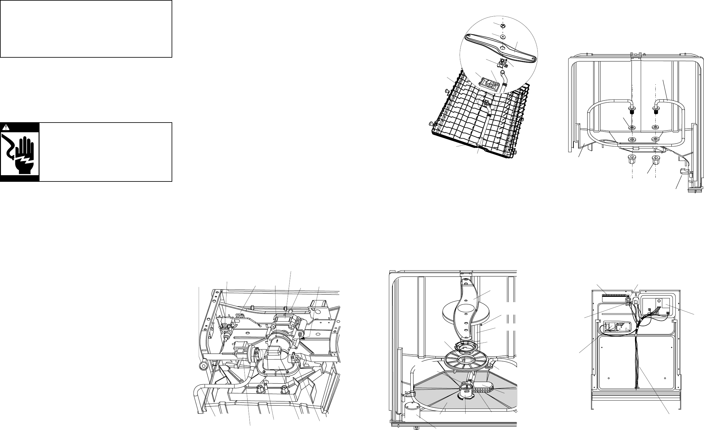
DOOR COMPONENTS (Figure 5)
The door components are accessible by removing three screws
from each side of inner door and two screws at the bottom of
the door. Carefully separate the inner door panel from the
outer door panel. The active vent can be accessed by removing
the screws on the escutcheon.
N.D. 913-07
Certain internal parts are intentionally
not grounded and may present a risk of
electric shock only during servicing.
Service personnel – DO NOT contact the
following parts while the appliance is
energized:
heating element, water valve,
main pump and drain pump and active
vent motor (if present).
WARNING
CALROD® HEATING ELEMENT
To Remove Heating Element (Figure 4):
1. Disconnect Power and remove wire leads from heating
element.
2. Unscrew two heating element nuts.
3. Remove heating element supports.
4. Lift and remove heating element.
WASHABILITY COMPLAINTS
Hot Water – Ample supply of water at 120°F minimum tem-
perature is necessary. Do not use dishwasher soon after using
clothes washer or filling bathtub.
Loading – Consult Owner’s Manual on loading procedures.
Amount of Water – Make sure dishwasher is level. Check water
level, allowing dishwasher to fill normally for first fill. The
water level should be to the center of the float dome. If water
level is low, check for clogged screen in water valve and check
float switch.
Detergent Module Leakage – Some moisture in cup is normal.
Detergent must not be soaking wet, oozing out and down
the inner door panel. If a leak is detected, check detergent
module door lid, latch operation, and gasket seal.
Proper Amount of Detergent – Use full detergent cup of fresh
detergent in hard water. Use only enough detergent to get
good wash performance in soft water.
Rinse Agent – Use rinse agent if spotting is a problem.
Water Valve – Check valve for intermittent operation. Valve coil
can be direct tested. Allow to heat normally, then check to see
if coil opens.
Spray Arm – Check to be sure spray arm spins freely and jets
are not clogged.
FILTER AND DRAIN SYSTEM
Will Not Pump Out
1. Enter service mode and check drain pump operation (see
service mode).
2. Check cover inlet (Figure 3) in the bottom of the tub. Make
sure that it is clear of food particles.
3. Check for blocked or partially blocked drain line and air gap.
4. Check routing of drain hose system. It must be free from
kinks.
5. Remove lower spray arm (Figure 3).
6. Remove main conduit mounting screw (Figure 3).
7. Lift main conduit tab, pull and rotate main conduit out of
hub (Figure 3).
8. Remove the cover inlet, check sump and drain outlet
(Figure 3). It may be blocked by a toothpick or other object.
9. Check drain pump valve (Figure 1) for correct operation.
Water should flow only from the pump to the high drain
loop.
10. Drain line check valve (Figure 1) must pass water in the
drain line direction only.
MOTOR-PUMP MECHANISM
Motor Stalled-Hums
1. Disconnect Power. Try to turn motor shaft clockwise to
determine if seal is stuck and can be broken loose.
If motor shaft cannot be turned, cutter blade may be bound
up. Proceed to step 2.
2. On inside of dishwasher, remove the cover inlet (Figure 3)
and reach down into the sump (Figure 1). Check for block-
ages such as bone, wire ties, etc. If it contains debris, clean
thoroughly. If motor shaft cannot be turned, remove
mechanism.
To Remove Motor-Pump Mechanism:
1. Remove cover inlet (Figure 3). With syringe, remove all water
from sump (Figure 3).
2. Loosen main pump clamp and pump connector clamp
(Figure 1).
3. Remove hanger that holds motor to tub frame (Figure 1).
4. Motor-pump mechanism can now be removed from under
dishwasher.
To Remove Lower Arm and Fine Filter Assembly (Figure 3):
1. Remove lower rack from dishwasher.
2. Gently lift and rotate lower spray arm counter clockwise to
remove.
3. Rotate nut hub counterclockwise to remove. Gently lift fine
filter assembly up. Remove fine filter drain from sump.
4. Clean fine filter screen if soil is present.
5. To reinstall fine filter and lower spray arm reverse procedure.
NOTE: When installing fine filter make sure the drain port of the
filter is engaged with the drain for the fine filter.
Drain
Pump
Turbidity
Sensor
High Drain
Loop
Water
Valve Flood
Switch
Pump
Connector
Clamp
Hanger
Main
Pump
Clamp
Drain Line
Check Valve
Drain Pump
Valve
Sump
Motor
Figure 1
Figure 2
Conduit Carrier
Hub
Middle
Spray
Arm
Mid
Bracket
Nut
Bearing
Upper Rack
Tab
Mid Conduit
Screw
(Optional)
TO SERVICE WASH ARM ASSEMBLIES:
Check Wash Arms
1. Check holes in spray arm for bits of
china, seeds and other foreign
matter.
2. Check spray arms for rotation.
To Disassemble Mid-Level
Arm (Figure 2):
1. Pull upper rack
all the way out.
2. Remove nut on
bottom of mid arm.
This will allow the
mid arm and
bearing to be
removed.
3. To remove
conduit,
remove screw
(some models)
from hub.
Press tab on
side of mid
bracket to release
the hub and mid conduit.
4. To reinstall arm, reverse procedure.
NOTE: Mid arm to be installed with spray jets facing the
upper rack. Bearing to be placed between nut and bottom
of mid arm.
Figure 3
Lower
Spray Arm
Nut Hub
Cover Inlet
Hub
Float Dome
Coarse Filter
Fine Filter
Drain Port
Fine Filter
Assembly
Main Conduit
Mounting Screw
Main Conduit
Drain For
Fine Filter
Main Conduit
Tab
Figure 4
Tub
Nut
Heating Element
Support
Heating
Element
Heater
Grommet
Harness
Detergent
Module
Interlock
Switch
Assembly
Electronic
Control
Active Vent
Flapper
Figure 5
165D6290G033
Pub. No. 31-30463
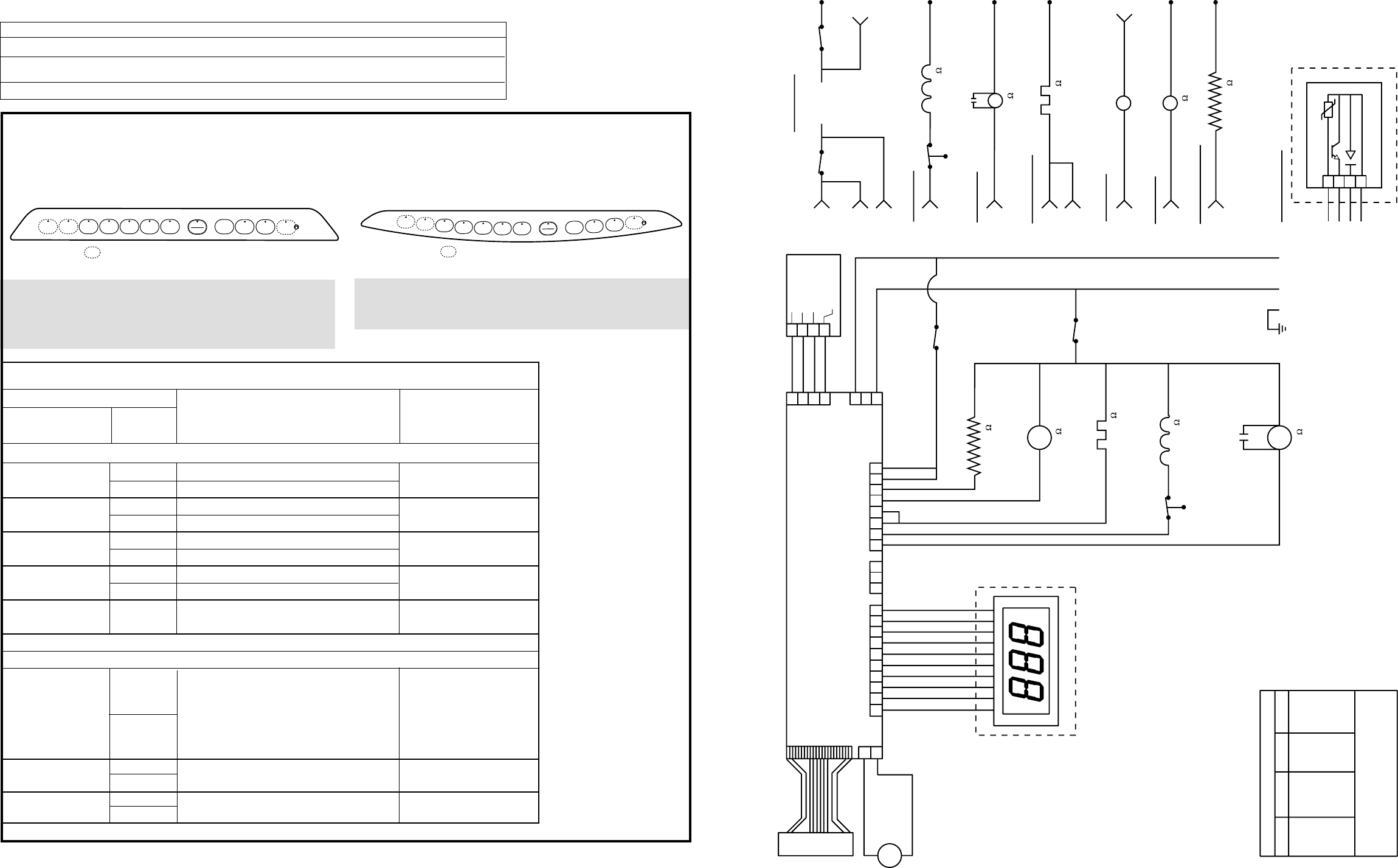
THIS DISHWASHER IS PROGRAMMED WITH A SERVICE MODE TO AID THE TECHNICIAN IN TROUBLESHOOTING THE DISH-
WASHER. EACH COMPONENT MAY BE CYCLED TO DETECT IF IT IS FUNCTIONING CORRECTLY. COMPONENTS ARE CYCLED BY
PRESSING KEYPADS TO THE RIGHT OR LEFT OF THE START/RESET KEYPAD. DETERMINE WHICH TYPE OF CONTROL PANEL IS
PRESENT (FLAT OR BOWED) AND THEN USE THE MATRIX BELOW TO DETERMINE HOW TO CYCLE EACH COMPONENT.
FLAT PANEL BOWED PANEL
TO ENTER SERVICE MODE :
PRESS THE COOKWARE (POTS & PANS ON SOME MODELS)
AND THE HEATED DRY KEYPAD SIMULTANEOUSLY FOR 3
SECONDS.
TO EXIT SERVICE MODE :
PRESS THE START/RESET KEYPAD AT ANYTIME TIME TO EXIT.
*NOTE : Service mode may
be used for 30 minutes
maximum. After 30 minutes
the service mode will
automatically turn off.
**NOTE : Component will be
activated for indicated
time. Component may be
deactivated by pressing
the same keypad that was
pressed to activate the
component.
TRITON XL SERVICE MODE TEST MATRIX *
KEYPAD
CONTROL DESCRIPTION TIME in seconds**
PAD TYPE
Keypads to the left of the Start/Reset keypad (Selections)
FLAT Activates Drain Pump
1L BOWED Activates Detergent Module 75
FLAT Activates Detergent Module
2L BOWED Activates Main Pump 60
FLAT Activates Main Pump
3L BOWED Activates Heating Element 75
FLAT Activates Heating Element
4L BOWED Activates Drain Pump 300
FLAT Activates Water Valve
5L BOWED
(Length of time is model dependent)
50 or 71
START/RESET Used to EXIT Service Mode
Keypads to the right of the Start/Reset keypad (Enhancement/Extras)
Activates the following in order:
Status LEDs; Wash LEDs;
1R FLAT Start/Reset and Option LEDs; 3 seconds each cycle
BOWED finally “888” will be shown
on the 3 digit display
(some models)
FLAT
2R BOWED Opens Active Vent
FLAT
3R BOWED Closes Active Vent
FLASHING DISPLAY LIGHTS
Status Indicator Lights What It Means
START/RESET
Cycle has been interrupted by pressing the
START/RESET
keypad. Light will quit
flashing after the dishwasher automatically drains out the water.
CLEAN
Unit has no water. Check the water supply. If water is turned on call for service.
WARNING:
POWER MUST BE DISCONNECTED BEFORE SERVICING THE APPLIANCE.
5L 3L 2L 1L
4L START
RESET 1R 2R 3R 4R
Indicates Keypad Used Only on Some Models
165D7995P001
1L
START
RESET
2L
3L
4L
5L 1R 2R 3R 4R
Indicates Keypad Used Only on Some Models
K
E
Y
P
A
D
CONTROL CIRCUIT BOARD
3-DIGIT DISPLAY
M
ACTIVE
VENT
MOTOR
BX
RX
J7
KEYPAD
12345678910 123 12345678
1
2
J5
ACTIVE
VENT
3-DIGIT DISPLAY
J8
PQA
J10
POWER SWITCHING
J2
1
2
3
1
2
3
4
TURBIDITY/
TEMPERATURE
SENSOR J3
---THIS CIRCUIT NOT IN
ALL MODELS
J1
POWER
SUPPLY
1
2
3
4
NTC
RECEIVER EMITTER
TRANSMITTER
CATHODE
Vcc
YB
NX
SX
OX
M
M
BW
NO COM
BX
DOOR
INTERLOCK
NO COM
WX
DOOR
INTERLOCK
WR
DETERGENT MODULE
RY WR
WR
WR
WR
NX WR
CIRCULATION
PUMP
GY
NL1
WX
BX
PX YX
FLOOD
SWITCH
CNO
WATER VALVE
725-1200
19.4-19.8
VX
HEATING ELEMENT
RX
DRAIN PUMP
1200-2800
1
2
3
4
YB
NX
SX
OX
NTC
TURBIDITY SENSOR
STRIP CIRCUITS
G
10
BXBW
BW
BX
NO COM
J2-7
J2-8
J1-3
J1-1
NOCOM
WX DOOR WR
DOOR
115V 60HZ
WATER VALVE
J2-2 PX
FLOOD
SWITCH WATER VALVE
WR
725-1200
CNO
PUMP MOTOR
J2-1
M
PUMP
WR
NX
10
HEATING ELEMENT
J2-3
J2-4
VX WR
HEATING ELEMENT
VENT MOTOR
J5-2 J5-1
M
RX BX
DRAIN PUMP
J2-5
M
RX WR
J2-6
DETERGENT MODULE
RY WR
1200-2800
DETERGENT MODULE
YX
19.4-19.8
COLOR CODE
LETTERS COLOR LETTERS COLOR
THE "X" INDICATES ONE SOLID COLOR- NO
TRACER. WIRES WITH TRACER SHOW
BOTH COLORS. EXAMPLE -WR IS WHITE
WITH RED TRACER.
AX
BX
CX
NX
OX
PX
LT. BLUE
BLACK
BROWN
DK. BLUE
ORANGE
PINK
RX
SX
TX
VX
WX
YX
RED
GRAY
TAN
PURPLE
WHITE
YELLOW
30
30
