GE Washer Compact WSLP1500 WSLS1500 31 9189
2013-04-09
: Pdf Ge - Washer - Compact - Wslp1500 - Wsls1500 - 31-9189 GE - Washer - Compact - WSLP1500 - WSLS1500 - 31-9189 GE, Camco, Hotpoint, Mofat
Open the PDF directly: View PDF ![]() .
.
Page Count: 37
GE Appliances
General Electric Company
Louisville, Kentucky 40225
31-9189
GE Compact Washer
WSLP1500J
WSLS1500J
Technical Service Guide
SEPTEMBER 2009
GE Consumer & Industrial
TEMP
LOAD OPTIONS
CYCLES
START
PAUSE
POWER
ULTRA
CLEAN

– 2 –
IMPORTANT SAFETY NOTICE
The information in this service guide is intended for use by
individuals possessing adequate backgrounds of electrical,
electronic, and mechanical experience. Any attempt to repair a
major ap pli ance may result in personal injury and property
damage. The man u fac tur er or seller cannot be responsible for the
in ter pre ta tion of this in for ma tion, nor can it assume any liability in
connection with its use.
WARNING
To avoid personal injury, disconnect power before servicing
this prod uct. If electrical power is required for diagnosis or test
purposes, disconnect the power immediately after performing the
necessary checks.
RECONNECT ALL GROUNDING DEVICES
If grounding wires, screws, straps, clips, nuts, or washers used to
complete a path to ground are removed for service, they must be
returned to their original position and properly fastened.
GE Consumer & Industrial
Technical Service Guide
Copyright © 2009
All rights reserved. This service guide may not be reproduced in whole or in part
in any form without written permission from the General Electric Company.
– 3 –
Table of Contents
Back Cover ...........................................................................................................................................................................19
Brake Control Motor ........................................................................................................................................................32
Circuit Board Connections ............................................................................................................................................17
Component Locator Views ...........................................................................................................................................15
Control Features ................................................................................................................................................................ 9
Control Panel and PCB ................................................................................................................................................18
Dispenser Assembly ........................................................................................................................................................25
Drain Pump .........................................................................................................................................................................25
Error Codes ..........................................................................................................................................................................34
Fuse .........................................................................................................................................................................................24
Installation ........................................................................................................................................................................... 6
Introduction ......................................................................................................................................................................... 5
Lid Switch and Harness .................................................................................................................................................23
Nomenclature .................................................................................................................................................................... 4
Outer Tub and Suspension Assembly .....................................................................................................................29
Pressure Sensor .................................................................................................................................................................21
Schematic.............................................................................................................................................................................36
Service Test Mode .............................................................................................................................................................35
Shaft Assembly ..................................................................................................................................................................33
Shaft Assembly and Brake Overview .....................................................................................................................31
Special Features ................................................................................................................................................................ 8
Top Cover ..............................................................................................................................................................................24
Troubleshooting ................................................................................................................................................................34
Unbalance Switch .............................................................................................................................................................22
Warranty .............................................................................................................................................................................37
Wash Basket .......................................................................................................................................................................28
Washer Components ......................................................................................................................................................18
Washing Motor and Belt ................................................................................................................................................27
Water Valve .........................................................................................................................................................................20
– 4 –
Model Number
Nomenclature
Capacity/Confi guration
L = Large
W S L S 1 5 0 0 J W W
Feature Package
S = Unitized Compact
Control Platform
S = Stationary
Engineering Revision
Color
WW = White
Model Year
F - 2005
G - 2006
H - 2007
J - 2008
K - 2009
Voltage
0 = US Voltage
Brand
W = GE Washer
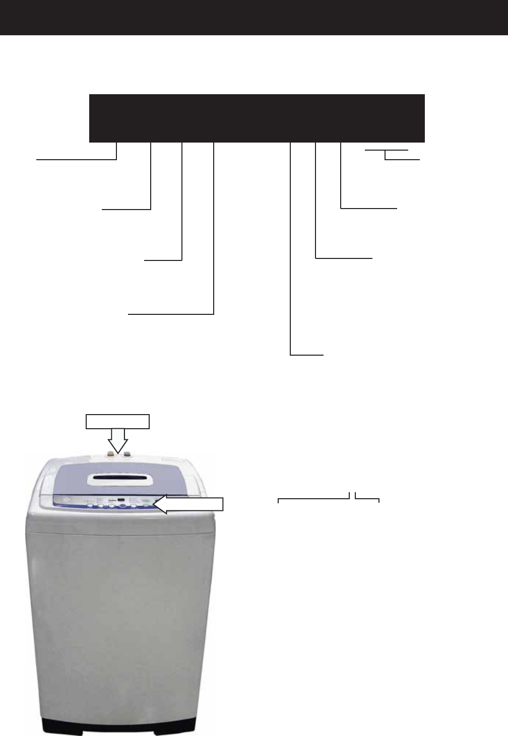
The nomenclature plate is located on the back
below the top cover.
The mini-manual is placed in an envelope
located under the control panel.
The letter des ig nat ing
the year re peats every
12 years.
Example:
T - 1974
T - 1986
T - 1998
Serial Number
The fi rst two numbers of the serial number
identify the month and year of manufacture.
Example: AS123456S = January, 2009
A - JAN 2009 - S
D - FEB 2008 - R
F - MAR 2007 - M
G - APR 2006 - L
H - MAY 2005 - H
L - JUN 2004 - G
M - JUL 2003 - F
R - AUG 2002 - D
S - SEP 2001 - A
T - OCT 2000 - Z
V - NOV 1999 - V
Z - DEC 1998 - T
Mini-Manual
Nomenclature
– 5 –
Introduction
The new GE Compact Washer has the following features:
Electronic One-Touch Controls with LED readout simplify cycle selection and provide accurate cycle •
times.
One-Touch Loading Sensing eliminates guesswork and helps reduce water waste.•
Ten wash cycles provide a setting for almost every load, from heavy cottons to casual synthetics; •
includes settings for light- to heavy-soil regular, whites, colors, casual and delicate fabrics.
Three wash/rinse temperatures ― A variety of temperatures provides great wash results and longer •
fabric life.
Four water levels match the water level to each load to reduce water waste per cycle.•
One Wash/Spin Speed ― Provides reliable cleaning performance for regular clothes.•
Custom Wash Cycle ― Saves a favorite cycle for future use. •
Dispenser adds diluted detergent and fabric softener at the correct time during the wash or rinse cycles.•
Overfl ow Protection ― Activates the drain pump whenever water reaches overfl ow level during a •
temporary stop, waiting action, or spin action. Overfl ow also sensed 3 times during a wash or rinse cycle.
Built-in Status indicators display certain associated error codes. •
The wash tub is constructed of durable stainless •
steel.
UV stabilizers are utilized on the control panel, •
top cover, and lid to prevent yellowing when
exposed to sunlight.
– 6 –
Installation
Location
Washer must be installed on fi rm fl ooring. •
Concrete fl ooring is best, but wood base is
suffi cient, providing fl oor support meets FHA
standards.
Washer should not be installed on rugs or •
exposed to the weather.
Install or store washer where it will not be •
exposed to temperatures below freezing.
Minimum clearances between washer and •
adjacent walls or other surfaces are: 2” either
side, 2” front, and 3” rear.
Minimum vertical space from fl oor to overhead •
shelves, cabinets, ceilings, etc., is 96”.
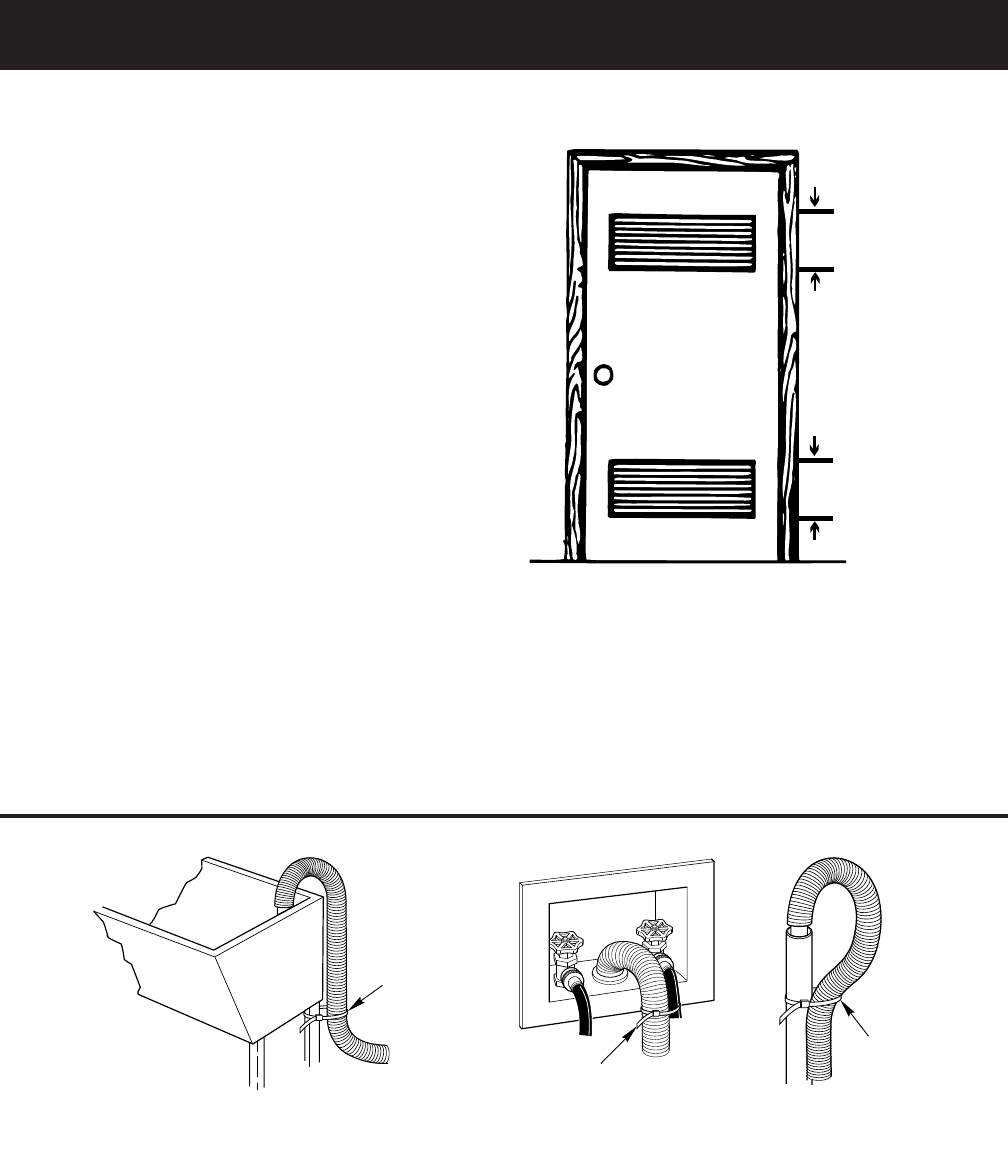
Closet doors must be louvered or otherwise •
ventilated and have at least 60 square inches
open area for washer only, or if the closet
contains both a washer and dryer, doors must
contain at least 120 square inches of open area,
equally distributed.
Note: The clearances stated are minimums.
Consideration must be given to providing adequate
clearances for installation and servicing.
60 sq. in.
(387.1 sq. c
m
60 sq. in.
(387.1 sq. c
m
Closet door
Plumbing
Water pressure must be 10 psi minimum to 150 psi maximum dynamic pressure measured at faucet.•
Water temperature on household water heater should be set to deliver water at 120° to 150°F (50° to •
66°C) in the washer when HOT wash is selected.
Shut-off valves should be supplied for both hot and cold water lines.•
Drain water into a standpipe or laundry tub. The discharge height must not be less than 30” nor more •
than 8’ above the base of the washer. The standpipe must be 1½” minimum inside diameter and must be
open to the atmosphere.
g
Cable Tie
Laundry Tub
GEA00044
Cable Tie
Cable Tie
Stand Pipe
GEA00045
(Continued next page)
– 7 –
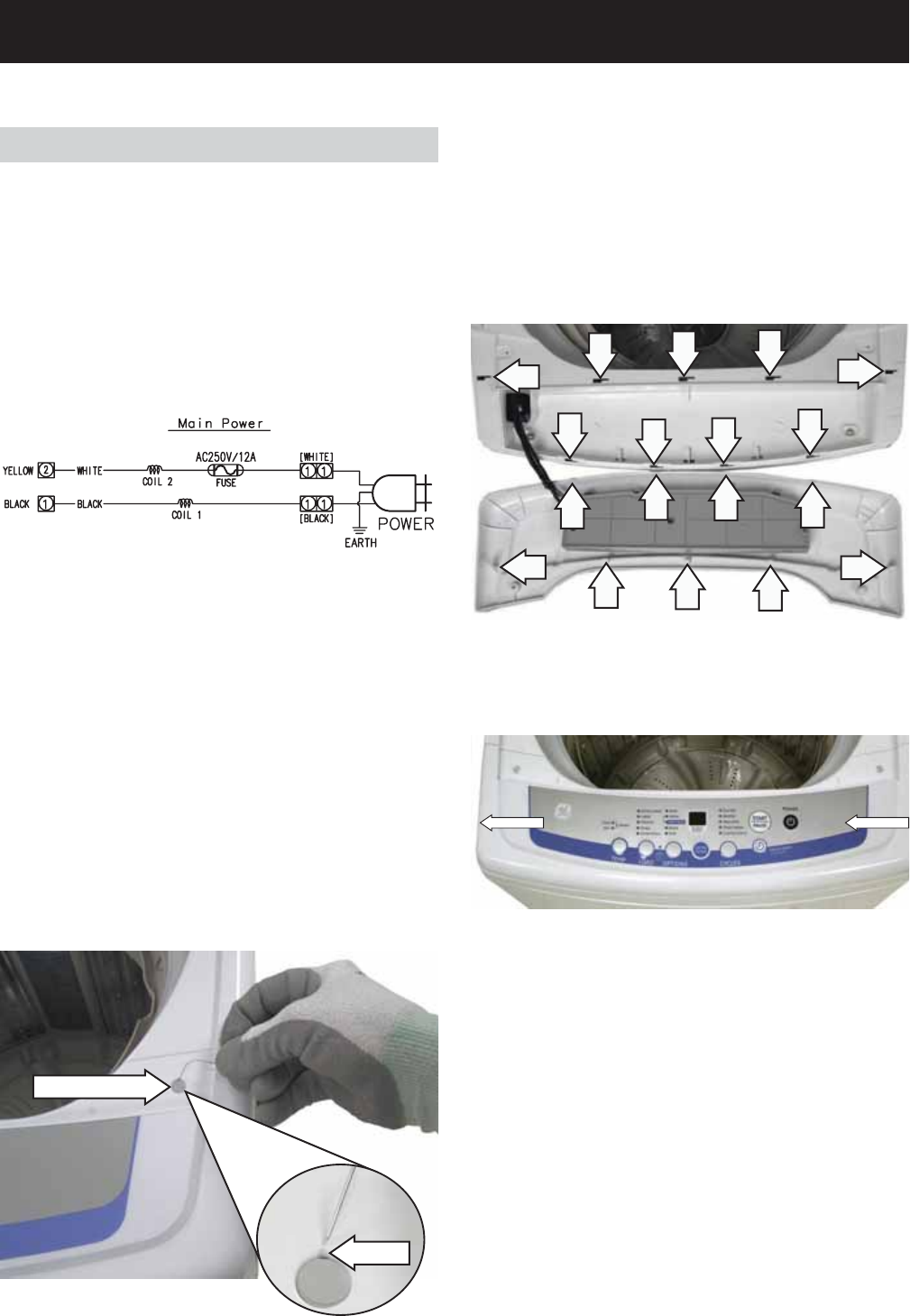
Electrical Wiring
National Electrical Codes or prevailing local •
codes and ordinances must be followed.
120V, 60Hz must be supplied and connected to •
an individual, properly grounded branch circuit,
protected by a 15- or 20-amp circuit breaker or
time delay fuse.
Wiring must be 2-wire with ground.•
Electrical Rating
Voltage AC......................................................120
Hertz ...................................................................60
Total connected load amperage ........10.0
For use on adequately wired 120-volt, 15-amp
circuit having 2-wire service with a separate ground
wire. This appliance must be grounded for safe
operation.
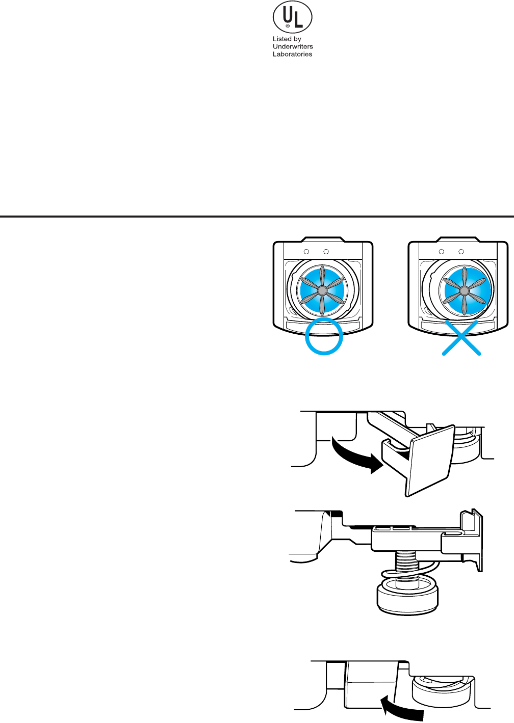
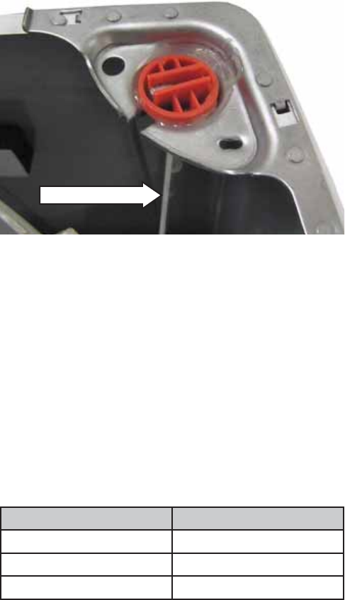
Leveling the Washer
Excessive vibration will occur if the washer is not
leveled. This will also trip the unbalance switch and
stop the washer. Check to ensure the washer is
level. With the door open, the spin basket should be
centered in the opening as shown in the “leveled”
view. If the spin basket is not in the center or
“unleveled” as shown at far right, level the washer
as follows:
Note: Be careful not to kick or step on the leveling
locks.
Pull out the leveling locks located at the bottom •
front of the left and right sides of the washer.
This releases the spring loaded leveling feet.
The washer will attempt to automatically level •
itself.
Check level at body panel line and adjust as •
necessary.
Push leveling locks back in. •
Manually level the rear feet (side to side).•
Leveled Unleveled
GEA00042
– 8 –
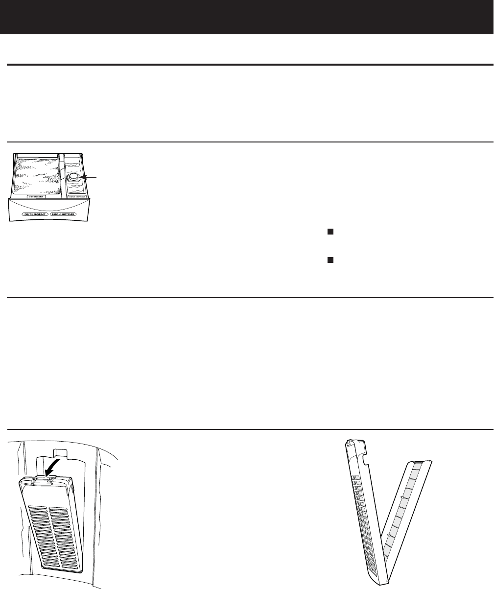
Detergent and Fabric Softener Dispenser Drawer
The detergent and fabric softener dispensers
will automatically release their contents at
the proper time during the cycle.
To Use the Detergent Dispenser:
Add measured detergent to the dispenser.
Make sure detergent is spread evenly and
is level.
To Use the Fabric Softener Dispenser:
Use only liquid fabric softener. Pour into
dispenser, using amount recommended
on package.
Do not fill any higher than the top of the
maximum fill tower.
Never pour fabric softener directly on
clothes. It may stain them.
Cleaning the Detergent and Fabric Softener Dispenser Drawer
1. Remove the drawer by opening it fully
then tilting the front of the door up.
Pull out.
2. Rinse the drawer with water. If necessary
use a soft cloth to wipe off any debris.
3. Line up the drawer with the opening and
push the dispenser drawer straight in.
Lint Filter
Clean the lint filter inside the wall of
the wash basket once a week for best
filtering results.
To remove:
Press the tab at the top of the filter and
pull out.
To clean:
Open the filter. Clean the filter with
a toothbrush.
Maximum
Fill Tower
Before starting the washer:
•Load the laundry in the washer.
•Add the detergent and fabric softener to the dispenser drawer.
Special Features
– 9 –
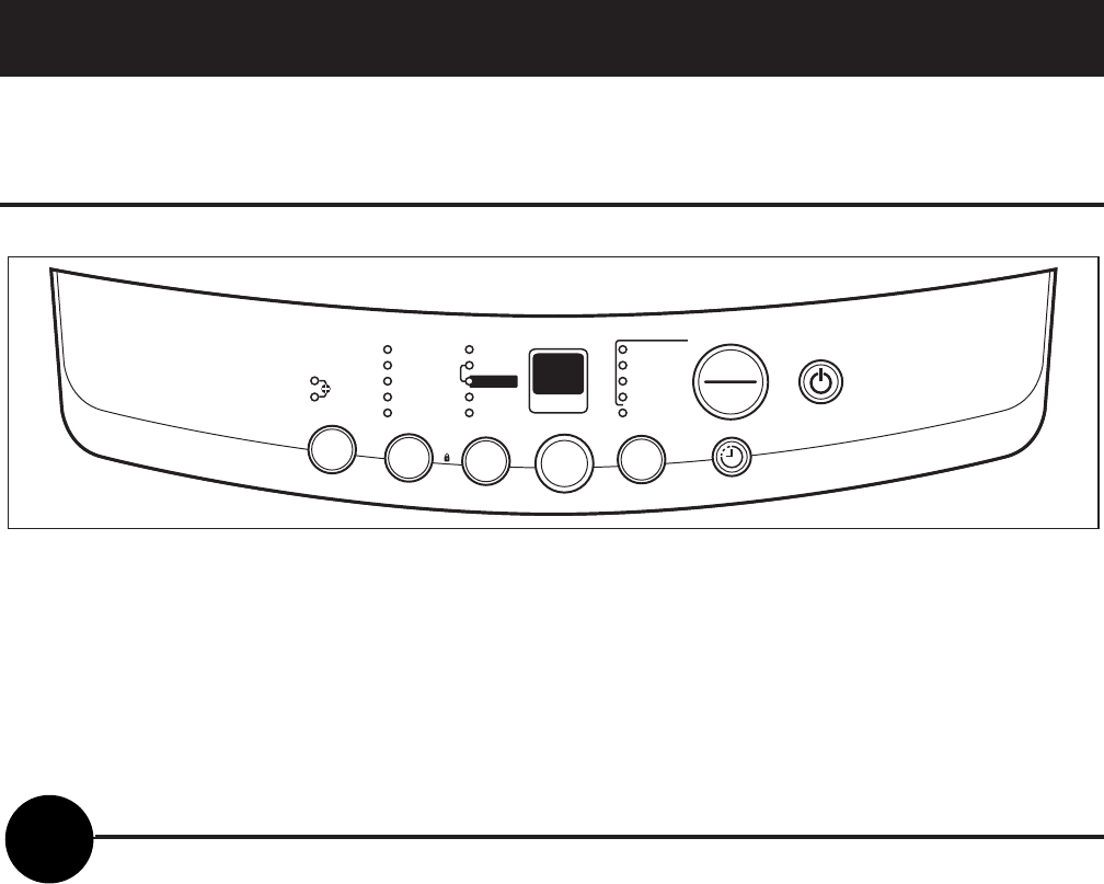
Control Features
(Continued Next Page)
EXTRA LARGE
LARGE
SOAK COLORS
WHITES
DELICATES
SPEED WASH
LOAD SENSING
CUSTOM CYCLE
WASH
RINSE
SPIN
COLD
HOT WARM
LOCK
HOLD 3 SECS TO
LOCK/UNLOCK
CONTROLS
MEDIUM
SMALL
EXTRA SMALL
HEAVY DUTY
EST. MINUTES
REMAINING
TEMP
LOAD
OPTIONS
ULTRA
CLEAN
CYCLES
DELAY WASH
1 to 18 HOURS
POWER
START
PAUSE
About the control and indicator settings.
Before starting the washer:
Load the laundry in the washer.•
Add the detergent and fabric softener to the dispenser drawer.•
To Use Automatic One-Touch Washing
The LOAD SENSING feature automatically senses the size of your load, tub fi lls with the appropriate amount
of water, and calculates the amount of wash time required to complete the cycle.
NOTE: When using the LOAD SENSING feature, it is normal for the pulsator to rotate before water fi lls in the
tub.
To choose the automatic • LOAD SENSING feature, press POWER ON/OFF. LOAD SENSING is the default
water setting. Manually selecting a load size cancels LOAD SENSING.
Select the desired • CYCLE, OPTION and water TEMP setting.
Then press • START/PAUSE.
The • COLORS indicator light will light up automatically unless you have selected one of the other LOAD
SENSING cycles such as WHITES, DELICATES, SPEED WASH, CUSTOM CYCLE or ULTRA CLEAN.
Then simply press • START/PAUSE.
NOTE: When the cycle is operating, the OPTIONS LED fl ashes. When the washer is in PAUSE, the LED does
not fl ash.
START
PAUSE

– 10 –
To Choose Your Own Cycle Selections
Soak+Wash Soak+Wash+Heavy Wash+Rinse Wash+Heavy Wash Rinse Wash Rinse Spin
Cycle +Rinse+Spin Duty+Rinse+Spin +Spin Duty+Rinse+Spin +Rinse +Spin Only Only Only
COLORS X X X X X X X X X
WHITES X X X X X X X X X
DELICATES X X X X X X X X X
SPEED X X X X X X X X X
WASH
CUSTOM X X X X X XXXX
CYCLE
ULTRA X
CLEAN
POWER ON/OFF
Press the POWER ON/OFF button to turn on the control panel.
WASH OPTIONS
Choose the wash options you would like to include in the cycle. Press the WASH OPTIONS button until all
the options you want to include are lit. More than one option can be selected.
1
2
LOAD SIZE
The water level should just cover the clothes. Adjust the load size accordingly. Loosely load clothes no
higher than the top row of holes in the washer basket.
3
WASH CYCLE
These wash cycles control the length of the washing process. The chart on the following page will help
match the WASH CYCLE setting to your specifi c laundry needs. When a cycle is selected, the automatic
temperature that the machine defaults to can be changed to whatever temperature you desire.
4
(Continued next page)

– 11 – (Continued Next Page)
The control can add an additional 4 wash cycles to each washing process. Each additional wash cycle adds
approximately 16 minutes.
To add additional wash cycles:
• Select a cycle using Automatic One-Touch Washing.
• Press the START/PAUSE pad.
• Anytime after the START pad is pressed, if the OPTIONS pad is pressed, the display will show 1.
• Pressing the OPTIONS pad again will change the display to 2. Selections from 1 to 5 are available.
NOTE: Once a selection is made, the control will automatically add additional time to the Est Minutes
Remaining display. 1 is the normal wash cycle without additional time added.
When the SPIN (only) option is selected, spin cycle time can be adjusted by pressing the OPTIONS pad after
the cycle has started. The display will show the actual minutes remaining in any SPIN (only) cycle.
Default Wash/Rinse Temperatures
Colors For easy care and wrinkle-resistant items. WARM/COLD
Whites For heavy to lightly soiled cotton, household HOT/COLD
linens, towels, work and play clothes.
Delicates For lingerie and delicate fabrics with COLD/COLD
light to normal soils.
Speed For one or two lightly soiled items
WARM/COLD
Wash that are needed quickly.
Custom Manually selected options of water
WARM/COLD
temperature and wash options
saved for future uses. (See NOTE 1.)
Ultra Maximizes detergent effi ciency by adding
WARM/COLD
Clean water in steps and slowly diluting the
detergent to the standard level. (See NOTE 2.)
NOTE 1. To use CUSTOM CYCLE, set the CYCLES selection to CUSTOM CYCLE. Select TEMP and OPTIONS
choices. Press START/PAUSE pad. Control remembers, and the next time CUSTOM CYCLE is selected, the
most recent settings will be displayed. CUSTOM CYCLE always utilizes LOAD SENSING. Load size cannot be
locked in.
NOTE 2. The washer partially fi lls, (approximately 75%) then begins to agitate for approximately 30 seconds.
The washer will then pause and continue to fi ll for about 10 seconds, then agitate. It repeats this process, in
varying degrees and stages, 4 times before the tub is at the correct water level and the machine completes
the wash cycle.
– 12 –
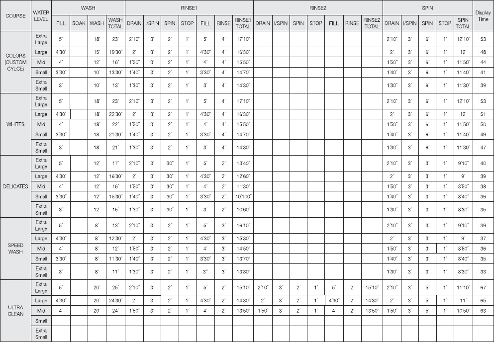
Twenty minute SOAK function occurs only when selected. This time has not been added to the ALL TIME 1.
column.
When one or more additional rinse cycles are selected, this shorter ADDITIONAL RINSE SPIN time is used 2.
for all rinse cycles except the fi nal rinse cycle. The fi nal rinse cycle uses the FINAL SPIN time. The time
from this ADDITIONAL RINSE SPIN column has not been added to the ALL TIME column.
The actual fi ll time is a function of water fl ow rate and may be more or less than the time specifi ed. If 3.
more time is needed, the countdown will pause. If less time is needed, the control deletes the remaining
fi ll time.
The rinse water valve fl ushes fabric softener from dispenser for 75 seconds ((10’ on / 5’ off) -5 times) at 4.
the beginning of the last rinse cycle only.
Time-Table of Function
(Continued Next Page)

– 13 –
About the control lock.
The control lock feature only locks the control during a cycle. Control lock does not lock the control in the
standby mode.
To activate control lock, press and hold LOAD and OPTIONS pads simultaneously for 3 seconds while the
washer is in a cycle. The display will alternate between CL and time remaining.
(Continued Next Page)

– 14 –
Water System and Filtering
Weight Recognition Function (Load Sensing)
The weight recognition function measures the washing load before water is supplied. •
The weight recognition function is canceled when water level key is pressed prior to the completion of •
weight recognition function.
If the current water level is above the lowest level at the beginning of weight sensing, it is automatically •
set as a high level.
If you change wash cycle after sensing weight, the high water level is automatically selected regardless •
of the water level decided by the sensing of weight.
Water Supply Function
Relations between water level, frequency, and water supply capacity are as follows:•
If the water level does not reach the selected level within 60 minutes after starting water supply, the •
Water Supply Error (7E) is displayed.
Supplementary water supply is performed during every washing or rinsing operation. The steps are as
follows:
Supply water to the water level selected.•
Perform the ACTIVATE operation for 1.5 minutes.•
Sense the present water level after stopping motor.•
Compare the present water level to the water level selected.•
If present water level is less than the water level selected, supply water to the water level selected. If •
present water level is greater than the water level selected, continue the washing or rinsing operation.
Total time of supplementary water supplying is not over 30 seconds.•
LEVEL GALLONS FREQUENCY (kHz)
EMPTY 0 25.2
EXTRA SMALL 8.00 24.1
SMALL 10.6 23.43
MEDIUM 12.4 23.03
LARGE 13.2 22.80
EXTRA LARGE 19.6 22.13
Water Level Frequency Chart
– 15 –
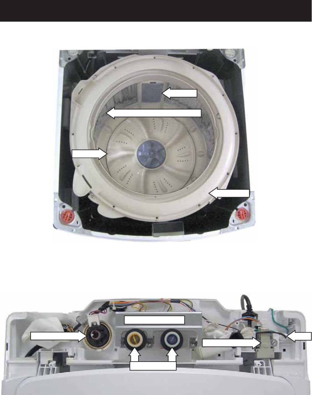
Component Locator Views
(Continued Next Page)
Top View
304 Stainless Steel Wash Basket
Tub Cover
Pulsator
Lint Filter
Water Valve Assembly
Water Inlet Ports
Unbalance Switch
Pressure Sensor Fuse
– 16 –
Component Locator Views (Con't)
Rear View
Tub Outlet Hose
Belt
Pressure Sensor Hose
Suspension Rod
Drain Pump
Drain Hose Connector
Pump Cleanout
Dispenser Drawer
– 17 –
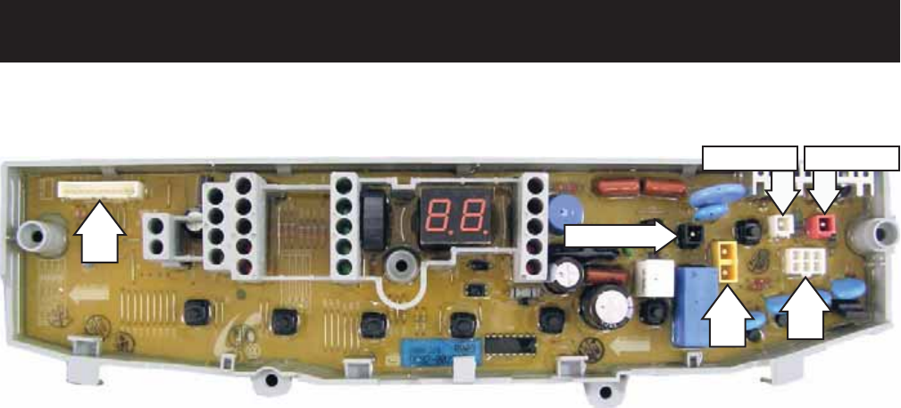
PCB (Printed Circuit Board)
Circuit Board Connections
CN1 - Door Switch, Unbalance Switch, Pressure Sensor
CN2 - Line Voltage
CN3 - Neutral, Neutral to Water Valve Solenoids
CN4 - Washing Motor
CN5 - Washing Motor, Washing Motor Condenser
CN6 - Water Valve Solenoids, Brake Control Motor, Drain Pump Motor
CN1
CN3 CN6
CN2 (BLK)
CN5 (RED)
CN4 (WHT)
– 18 –
Washer Components
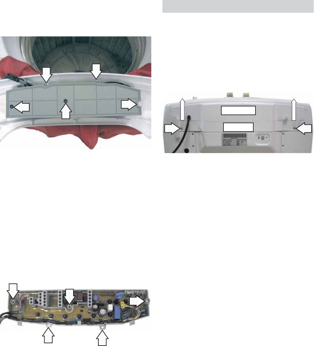
Control Panel and PCB
The control panel is located on the front of the top
cover. The control panel consists of an LED display,
and an 8 push-button keypad that operates a
printed circuit board (PCB).
The PCB is supplied with 120 VAC at PCB locations
CN2 pin 1 to CN3 pin 2.
A 12-amp fuse is installed in the white neutral line
and is located under the rear cover. (See Fuse.)
Caution: To prevent damage to the control panel,
place a cloth or towel over the front of the top cover.
5. Place the control panel face down on the
protected top cover.
Screw Cover
Notch
4. Slide the control panel to the left, then lift the
panel from the top cover.
3. Remove the 2 Phillips-head screws that attach
the control panel to the top cover.
Note: In the following step, 9 tabs located inside the
control panel are engaged in 9 corresponding slots
in the top cover.
Control Panel Removed from Top Cover
CN3
CN2
WARNING: Sharp edges may be exposed when
servicing washer. Use caution to avoid injury and
wear Kevlar gloves or equivalent protection.
To remove the control panel and PCB:
The control panel is attached to the top cover with 2
recessed Phillips-head screws (1 on each side). It is
necessary to remove 2 screw covers to access the
screws.
Open the lid.1.
In the notch provided, insert a straightened 2.
paper clip or small fl at blade screwdriver, then
pry and lift the 2 screw covers (1 on each side),
from the top of the control panel.
(Continued next page)
– 19 –
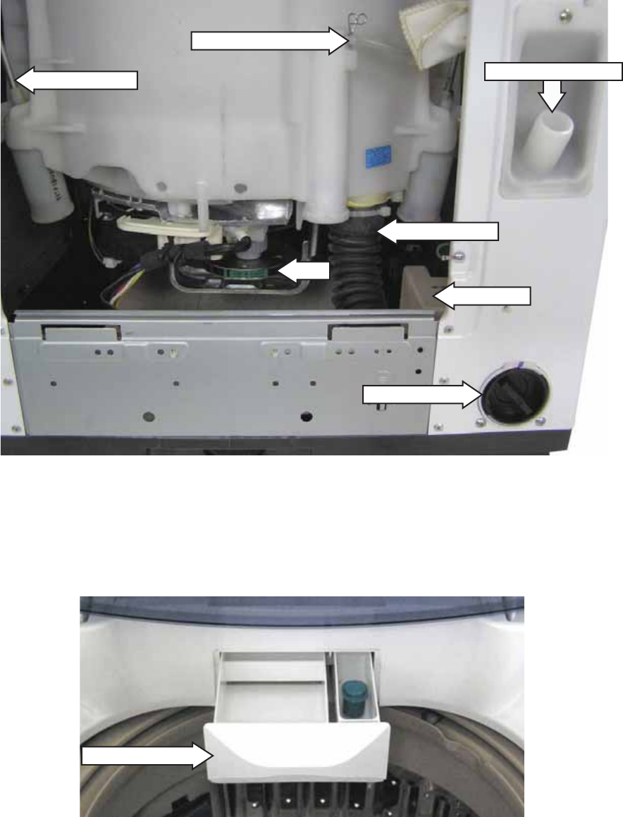
Back Cover
Removal of the back cover provides access to the
water valve, pressure sensor, unbalance switch,
fuse, and lid springs.
The back cover is held to the rear of the top cover
with 2 Phillips-head screws and 4 tabs. The tabs are
located inside the back cover. After removal of the
screws, the back cover can be lifted straight up.
BACK COVER
TOP COVER
Before reapplying power, check for proper •
button operation, press each button and listen
for an audible click.
When installing the control panel to the top •
cover, before sliding the panel toward the right,
make sure all panel tabs are engaged with slots
in the cover.
Caution:
To prevent misalignment of the control panel •
selector buttons to the PCB, when installing the
PCB to the control panel route the wiring as
shown below.
Make sure all screw locations on the PCB fully •
contact the control panel before installing the
screws.
7. Place the PCB wiring side up and note the wiring
locations and routing, then disconnect the
wiring from the PCB.
6. Remove the 5 Phillips-head screws that attach
the PCB to the control panel. Place the control
panel and the cloth or towel aside.
– 20 –
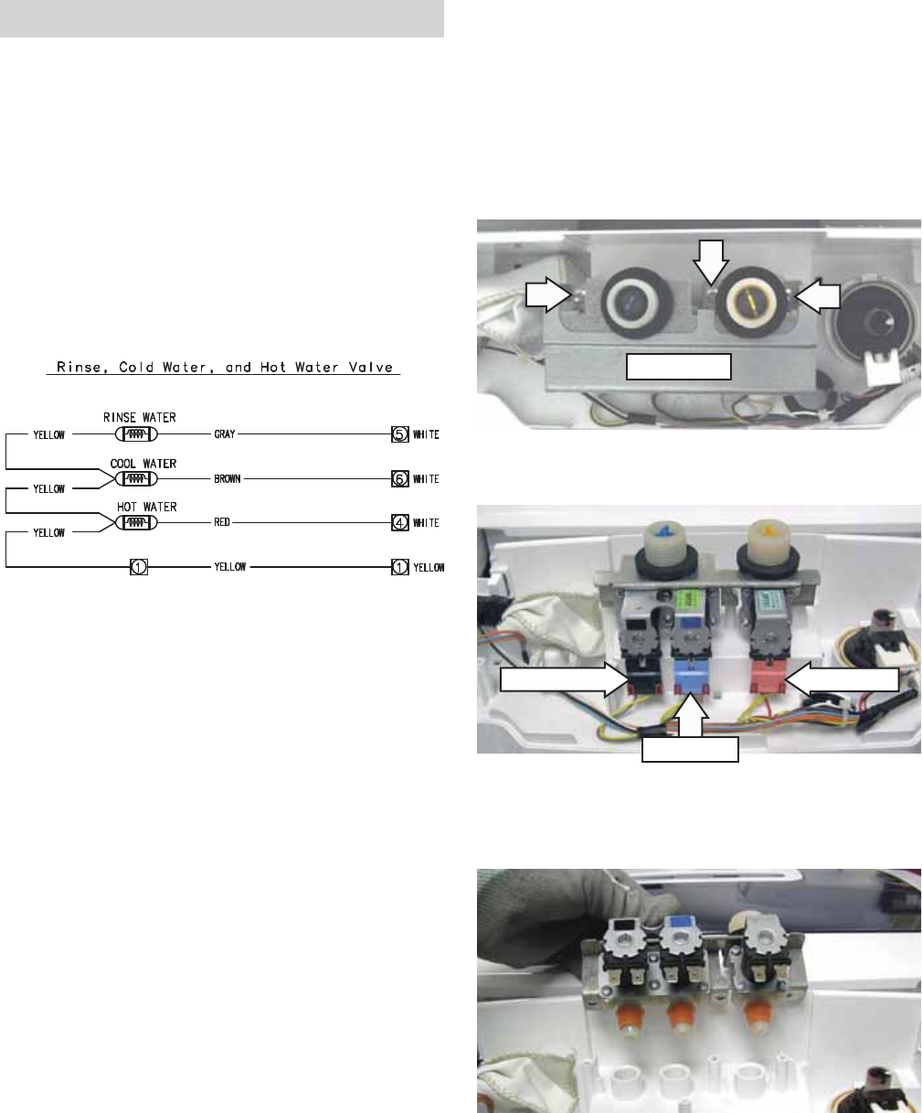
Water Valve
The water valve consists of a valve body and 3
solenoid coils. It is only available as a complete
assembly. Each solenoid controls a specifi c water
function.
Each coil on the water valve assembly has an •
approximate resistance value of 1.2K Ω.
The water valves receive power from the PCB. •
When energized, there should be approximately •
120 VAC at the appropriate coil.
3. Disconnect the 3 wire harnesses from the valve.
VALVE COVER
4. Lift the water valve straight up and remove the
valve from the top cover.
The water valve is located at the rear center of the
top cover.
To remove the water valve:
Remove the back cover. (See 1. Back Cover.)
Remove the 3 Phillips-head screws and lift the 2.
valve cover from the valve.
CN6
CN6
CN6
CN3
Rinse Water Hot Water
Cool Water
– 21 –
Pressure Sensor
The pressure sensor is connected by a clear hose to
an air reservoir near the bottom of the outer tub and
operates by a frequency (kHz) signal to the inverter
board.
The pressure sensor wires (violet, orange, and pink)
are connected at pins 1, 2, and 3 at CN1 on the PCB.
(See Circuit Board Connections.)
The approximate resistance value of the transducer,
measured between the pink and violet wires, is
approximately 23 Ω.
When the water level rises in the washer tub, air is
trapped in the reservoir. As the water level rises, the
air pressure in the reservoir increases.
The pressure is translated into an electrical •
signal (frequency) by the pressure sensor.
The frequency will vary from approximately 27 •
kHz (empty tub) to 22 kHz (full tub).
This frequency can be measured at the pressure •
sensor between the orange and violet wires.
LEVEL GALLONS FREQUENCY (kHz)
EMPTY 0 25.2
EXTRA SMALL 8.00 24.1
SMALL 10.6 23.43
MEDIUM 12.4 23.03
LARGE 13.2 22.80
EXTRA LARGE 19.6 22.13
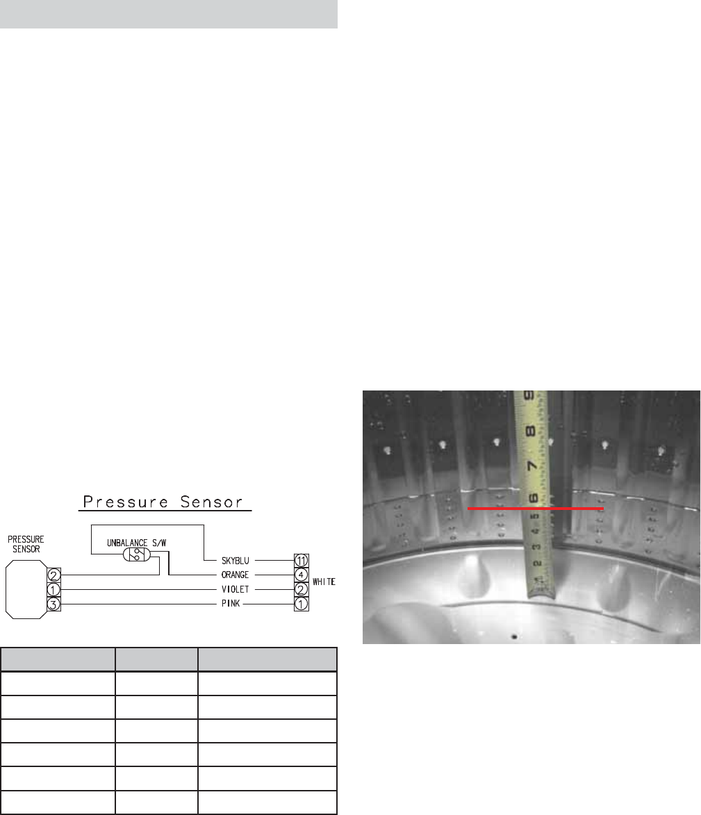
Pressure Sensor Test
If the pressure sensor is not operating correctly,
perform the following test:
Operate the washer on the spin cycle until all
remaining water is drained from the washer.
Clear the pressure switch air tube of any
obstructions such as lint, detergent or fabric
softener deposits, or foreign objects.
Check the approximate water levels at each load
selection. Water levels are measured from the
bottom of the wash basket:
EXTRA SMALL - 5 ½ inches
SMALL - 6 ¾ inches
MEDIUM - 7 ½ inches
LARGE - 8 ¾ inches
EXTRA LARGE - 11 ¾ inches
The frequency is monitored by the PCB, which turns
off the water valves when the desired water level is
achieved.
Note: The water level will vary slightly depending
on the load size, which is measured by the weight
recognition function and any supplementary water
needed. This information is sent to the PCB, which
then determines the appropriate water level.
Extra Small Water Level Shown
CN1
(Continued next page)
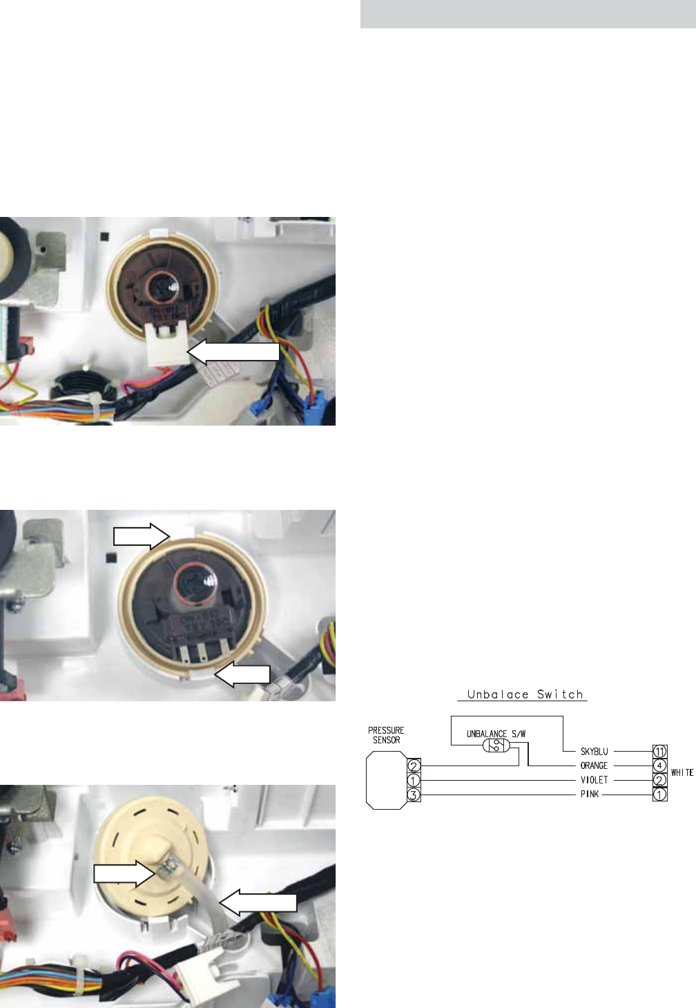
– 22 –
The pressure sensor is located on the top cover, left
of the water valve.
To remove the pressure sensor:
Note: Before disconnecting the hose from the
pressure sensor, be sure the water level is below the
bottom of the spin basket.
Remove the back cover. (See 1. Back Cover.)
Disconnect the pressure sensor wire harness.2.
Hook
Hook
3. Carefully push both hooks slightly outward, then
lift the pressure sensor.
4. Using pliers, squeeze the clamp and pull the air
tube off the pressure sensor.
Air Tube
Clamp
Disconnect
CN1
(Continued next page)
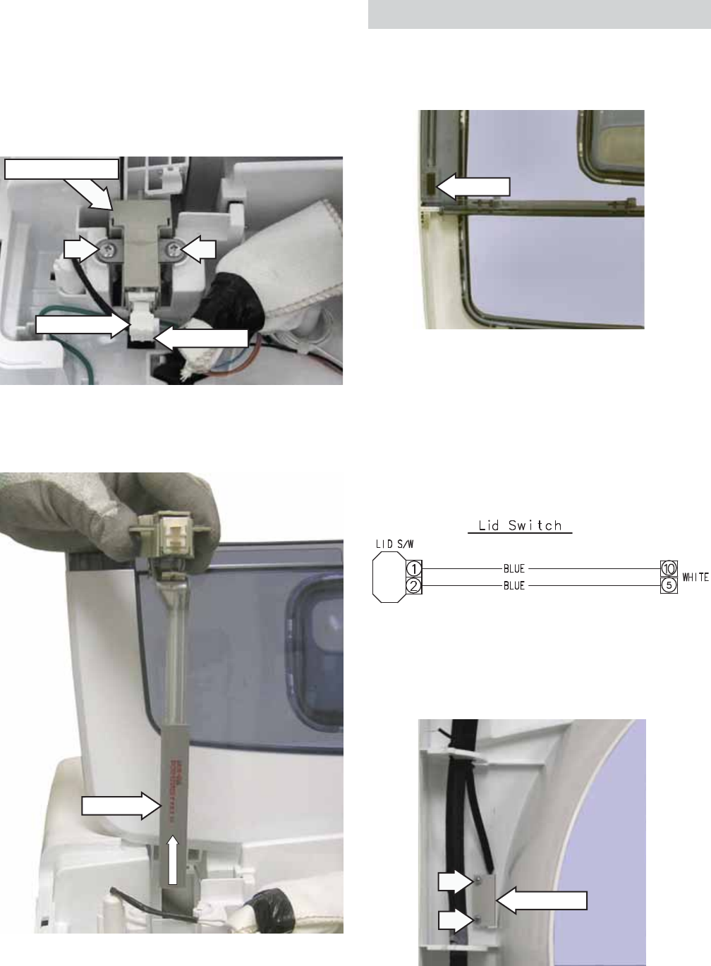
Unbalance Switch
The unbalance switch is located at the right rear
corner of the top cover. The switch actuator is
inserted through a hole in the top cover. The
normally open contacts will close when the
lid is closed. With the lid closed, the contacts
will momentarily open when an out of balance
load allows the outer tub to push the actuator
approximately 3/4-inch toward the rear of the
cabinet.
The fi rst two times the switch is tripped, the washer
stops, time is added to the display, tub fi lls with
water, agitates, then spins again.
If the switch is tripped a third time, Ub will appear
in the display. With Ub displayed, the lid will need
to be opened, the clothing redistributed, and START
selected to complete the cycle.
The continuity of the switch can be checked at the
switch terminals or at the PCB location, CN1 pin 4
and pin 11.
An open unbalance switch will:
Cause • Lo, lid open, to appear in the display
Not stop the fi ll function •
Stop the wash cycle•
Stop the drain pump •
Stop the spin cycle•
Not stop the drain pump operating during •
overfl ow protection.
Note: Lo, lid open, shown in the display can be
caused by an open lid switch or open unbalance
switch. Test each switch separately to determine
which one is at fault.
The unbalance switch and actuator are replaced as
an assembly.
– 23 –
4. Lift and remove the unbalance switch from the
washer.
Disconnect Disconnect
Unbalance Switch
Actuator
To remove the unbalance switch:
Remove the back cover. (See 1. Back Cover.)
Disconnect the 2 wires from the switch.2.
Remove the 2 Phillips-head screws that attach 3.
the switch to the top cover.
An open lid switch affects washer operation the
same as an open unbalance switch. (See Unbalance
Switch.)
Note: Lo, lid open, shown in the display can be
caused by an open lid switch or open unbalance
switch. Test each switch separately to determine
which one is at fault.
Magnet
Lid Switch
Note: When replacing the lid switch, note the
routing of the wire harness.
Lid Switch and Harness
When the lid is in the closed position, a magnet
located inside the front half of the lid will activate
and close the lid switch contacts.
CN1
The lid switch is attached to the inside of the top
cover with 2 Phillips-head screws. The top cover
must be lifted to access the lid switch. (See Top
Cover.)
– 24 –
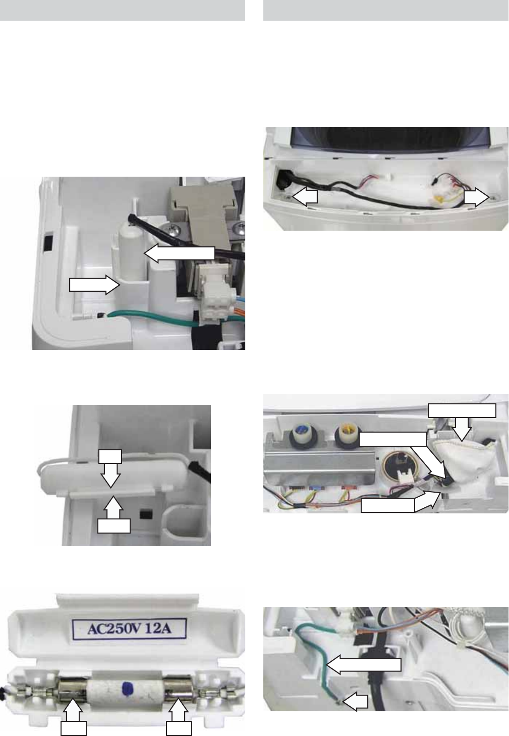
Fuse
The washer utilizes a fuse connected in the neutral
line of the top cover wire harness. The fuse is rated
at 250 VAC and 12 amps. The fuse and fuse holder
are located at the right rear corner of the top cover.
To remove the fuse:
Remove the back cover. (See 1. Back Cover.)
Lift the fuse holder from the recess in the top 2.
cover.
3. Disengage the latch from the tab and open the
fuse holder.
4. Remove fuse from fuse clips.
Recess
Fuse Holder
Latch
Tab
Clip Clip
Top Cover
To remove the top cover:
Remove the control panel and PCB. (See 1. Control
Panel and PCB.)
Remove the 2 Phillips-head screws that attach 2.
the front of the top cover to the cabinet.
3. Remove the back cover. (See Back Cover.)
4. Remove the foam tape.
Note: In the following step, 2 wire harnesses are
located inside the wire harness cover.
5. Unwrap the electrical tape and remove the wire
harness cover.
6. Disconnect the 2 wire harnesses.
Harness Cover
Electrical Tape
Foam Tape
9. Lift the top cover from the cabinet.
Ground Wire
7. Remove the pressure sensor and air tube clamp.
(See Pressure Sensor.)
8. Remove the Phillips-head screw that attaches
the ground wire to the cabinet.
– 25 –
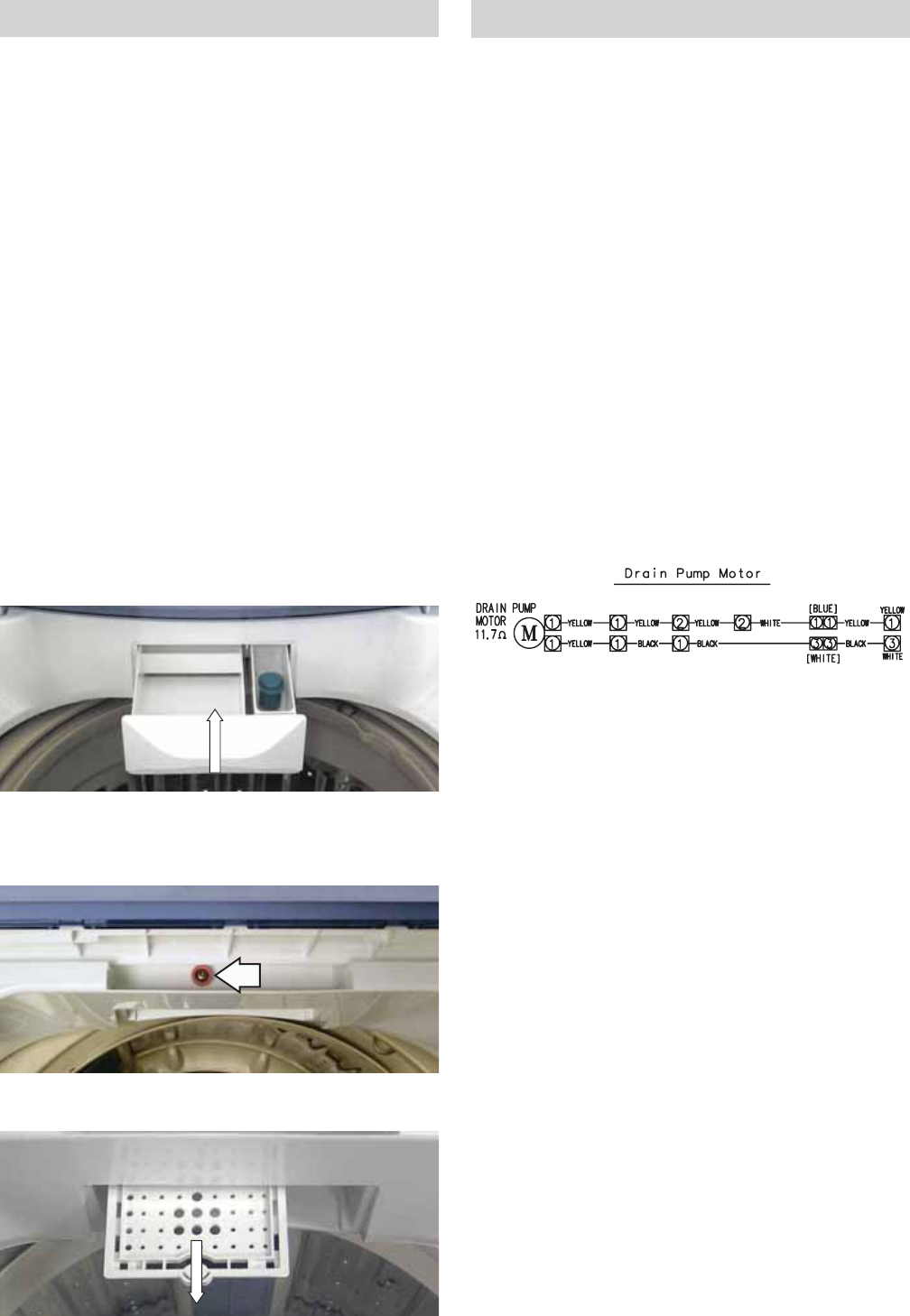
Dispenser Assembly
The dispenser assembly provides automatic
dispensing of detergent and fabric softener as long
as the user fi lls the compartments prior to starting
the washer.
The products added to the dispenser are diluted
with water before they are dispensed into the wash
basket. This is controlled by the PCB.
Each of the 3 water valve solenoids is controlled by
the PCB to release at the right time during the wash
and rinse cycles. Water released to dilute detergent
passes through a guide that evenly distributes
water into the detergent reservoir. Water released
in the fi nal rinse cycle fl ows directly into the fabric
softener reservoir.
To remove the dispenser assembly:
Open the lid and pull the dispenser drawer out 1.
to the stop position.
Tilt the front of the drawer up and pull it out of 2.
the dispenser cavity.
3. Remove the Phillips-head screw that attaches
the guide to the top of the cavity.
4. Slide the guide out of the cavity.
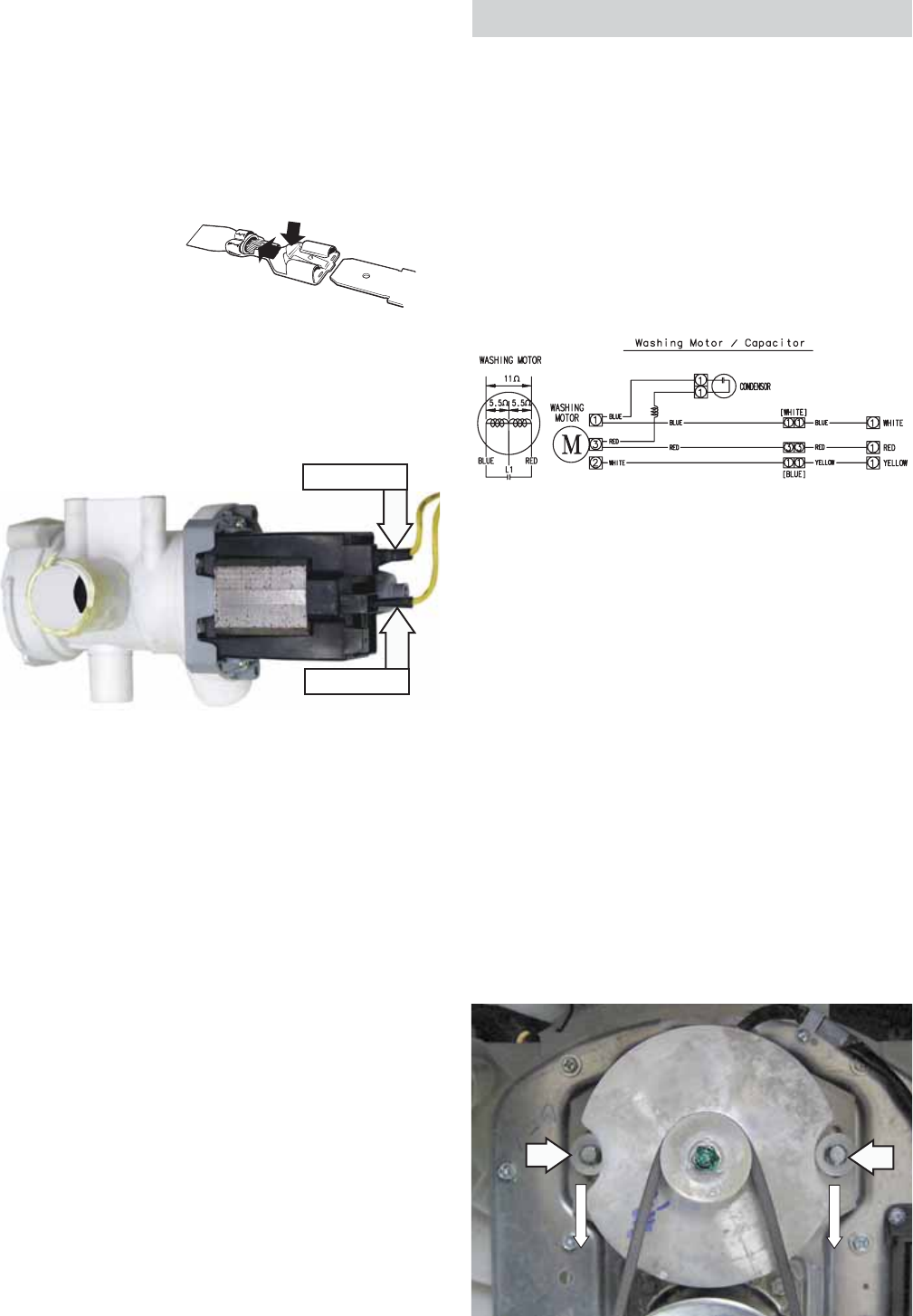
Drain Pump
The pump consists of a 120-VAC, 60-Hz motor,
impeller, impeller housing, and a removable strainer
that helps prevent foreign objects from entering the
pump impeller and drain outlet.
The pump runs whenever the washer is in the •
spin function of a cycle.
The drain pump runs if water reaches overfl ow •
level and the washer is plugged in.
The pump is capable of eliminating 4 gallons (15 •
liters) per minute.
Recommended minimum standpipe diameter is •
1 ½ inches.
Standpipe maximum height is 96 inches, •
measured from the fl oor at the washer location.
The pump motor has an approximate resistance •
value of 11.8 Ω.
CN3
CN6
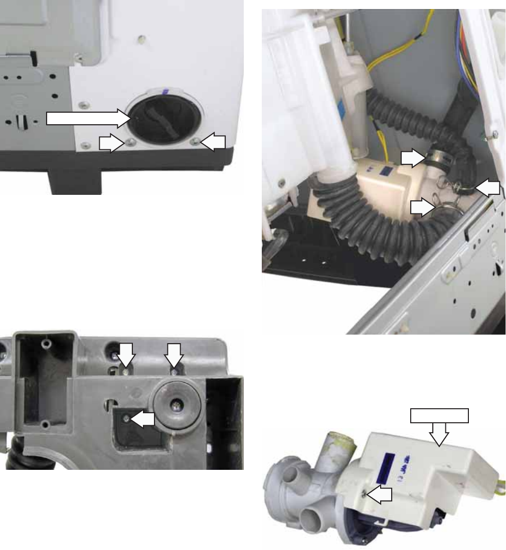
The drain pump is located inside the left rear corner
of the washer.
To clean the impeller and impeller housing:
WARNING: The drain pump is not grounded.
To avoid electric shock, unplug the unit before
servicing.
Note: The impeller can be accessed for cleaning
without removing the drain hoses.
Under normal conditions, approximately 1 quart
of water will drain out when the pump cleanout is
removed. Use care to avoid water spills.
Disconnect power to the machine.1.
Place a shallow pan under the drain cleanout.2.
Turn the pump cleanout counterclockwise 3.
approximately 2 turns, then pull outward.
Remove any debris or foreign objects from 4.
the strainer and interior of the pump before
reinstalling.
(Continued next page)
– 26 –
To remove the drain pump:
Remove the 2 Phillips-head screws and the 1.
access panel from the back of the washer.
Drain any remaining water from the washer. 2.
(See To clean the impeller and impeller housing,
this section.)
3. Remove the 2 Phillips-head screws, located
below the cleanout, that attach the pump to the
back of the cabinet.
Caution: To remove the drain pump, the washer
must be carefully placed on its front or side. To
prevent scratches to the surface of the washer,
place a towel or blanket on the fl oor.
4. Remove the 3 Phillips-head screws that attach
the pump to the bottom of the washer base.
(Continued Next Page)
Note: In the following step, the tub outlet hose is
diffi cult to remove due to a sealing compound used
at the factory.
a. Squeeze the clamp and slide it back.
b. Carefully break the tub outlet hose loose
by inserting a small fl at-blade screwdriver
under the hose to break the seal.
c. Remove the hose.
5. Remove the 3 hoses from the pump.
6. Remove the Phillips-head screw and the pump
cover from the pump.
Pump Cover
Pump Cleanout
– 27 –
Caution: To ensure there is no water leakage, care
must to taken when reinstalling and sealing the
hoses to the drain pump.
When installing, apply a thin coat of sealing
compound (part no. WH60X15) to the inner surface
of the drain hoses.
Note: The electrical terminal ends, which attach to
the drain pump, have locking tabs on them. These
tabs cannot be seen because they are encased
in plastic. To remove these terminals, grasp the
releasing locking tab of the terminal with needle-
nose pliers. Gently squeeze the pliers' jaws together
while pulling the electrical terminal from the drain
pump.
ELECTRICAL TERMINAL
RELEASE/LOCKING TAB
SHOWN WITH PLASTIC
COVERING REMOVED
7. Disconnect the 2 wires from the pump.
ELECTRICAL TERMINAL
RELEASE/LOCKING TAB
Disconnect
Disconnect
Washing Motor and Belt
The motor assembly consists of a reversible, AC
motor. The motor drives the shaft assembly pulley
with a V-belt.
On the motor plug, check for approximate
resistance values:
Blue to white and yellow - 5.5 Ω
Red to white and yellow - 5.5 Ω
Blue to red - 11 Ω (Can also be measured at PCB
CN4 to CN5.)
CN4
CN5
CN3
Caution: If the outer tub is not removed as an
assembly, to access the belt, the washer can be
carefully placed on its front or side. To prevent
scratches to the surface of the washer, place a
towel or blanket on the fl oor.
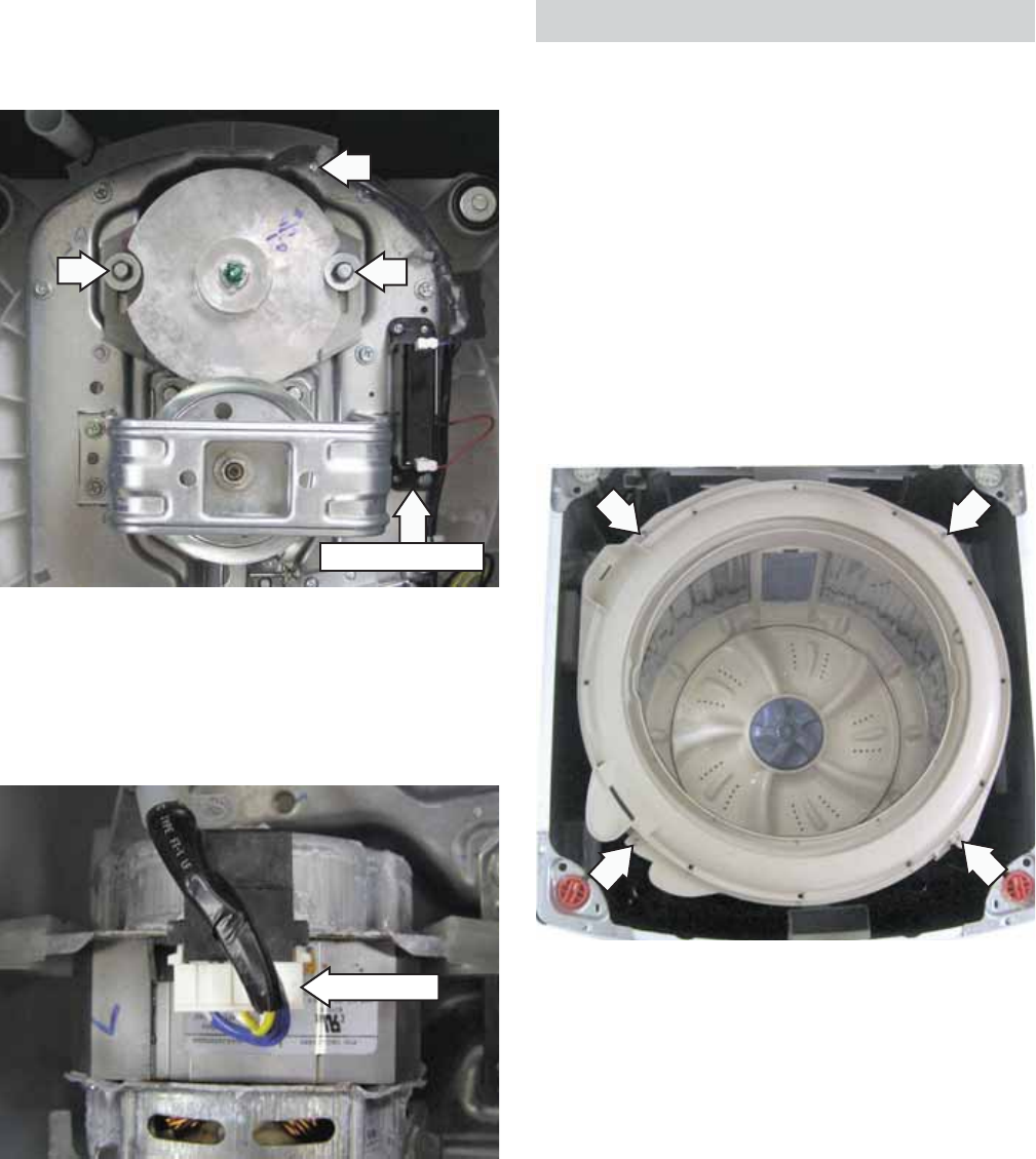
The washing motor is attached to the platform with
two 13-mm bolts. To replace it requires removing
the belt, two 13-mm (33/64” SAE equivalent) bolts,
and the Phillips-head screw that attaches the motor
wire harness to the platform. The motor can then be
lifted from the platform.
To remove the washing motor and belt:
1. Loosen the two 13-mm bolts that attach the
washing motor to the platform, then slide the
motor toward the shaft assembly.
2. Rotate the belt off the motor and shaft assembly
pulleys.
(Continued next page)
– 28 –
3. Remove the two 13-mm bolts from the motor.
4. Remove the Phillips-head screw that attaches
the motor wire harness to the platform.
5. Lift the motor, then place it harness-side up on
the platform.
6. Disconnect the wire harness from the motor.
7. Remove the 13-mm hex-nut that attaches the
motor pulley to the motor shaft.
* The washing motor utilizes a 42 μF condenser. The
condenser is a start capacitor. If the condenser is
open; the motor will hum, but not start.
The condenser is attached to the platform with 2
Phillips-head screws. (For location of condenser, see
photo after step 4.) Two wires are connected to the
condenser.
Disconnect
*Motor Condenser
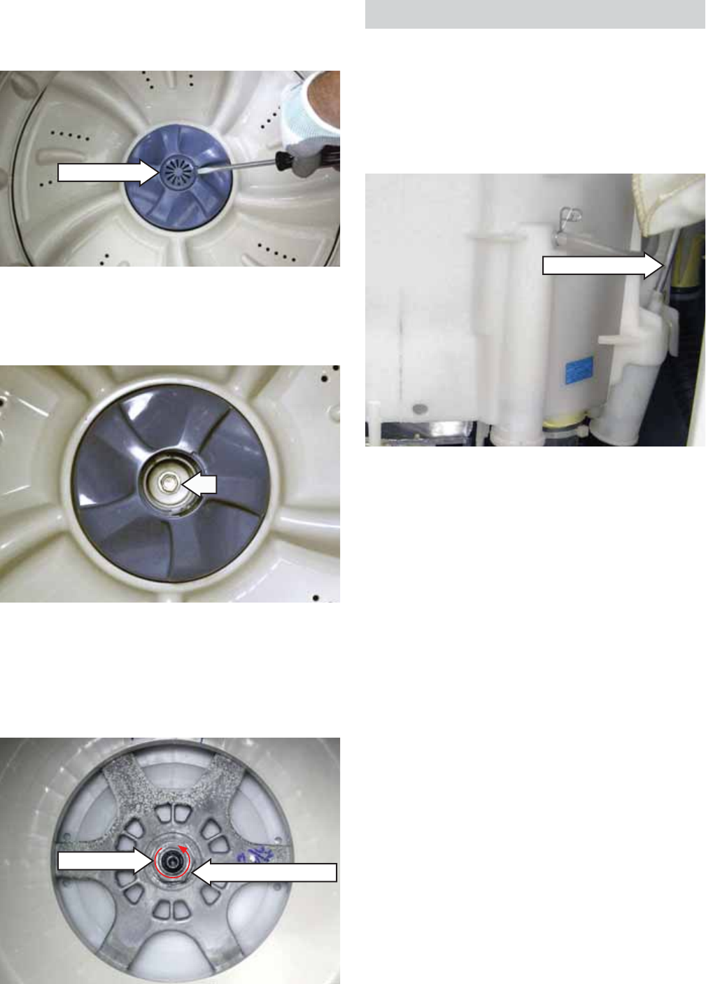
Wash Basket
The wash basket is contained inside the outer tub.
The wash basket is rotated by a belt-driven shaft
assembly. A 36-mm (17
/
16
-in. SAE equivalent) nut
attaches the wash basket to the shaft.
To remove the wash basket:
Drain the washer using the pump cleanout. (See 1. Drain Pump.)
Remove the top cover. (See 2. Top Cover.)
Remove the 4 Phillips-head screws that attach 3.
the tub cover to the outer tub. Remove the
cover.
(Continued next page)
– 29 –
4. Place a fl at blade screwdriver in the slot under
the pulsator cap. Gently pry up and remove the
pulsator cap.
6. Pull the pulsator assembly up and out.
7. Remove the 36-mm hex-head nut (loosen
counterclockwise), and wave washer that attach
the wash basket to the shaft.
8. Lift the wash basket out of the outer tub.
Pulsator Cap
5. Remove the 10-mm (13/32” SAE equivalent)
bolt that attaches the pulsator assembly to the
shaft.
(Continued Next Page)
36-mm Nut Washer (Under Nut)
Outer Tub and Suspension Assembly
The wash basket, outer tub, motor, and shaft
assembly are suspended by four rod and spring
assemblies. The rod and spring assemblies are
attached to each corner of the washer cabinet.
They extend down and connect to the bottom of the
outer tub.
To remove the outer tub:
WARNING: The outer tub assembly is heavy and
requires two people to remove it from the washer
housing. Care should be taken when removing and
installing the outer tub assembly.
Remove the top cover. (See 1. Top Cover.)
Remove the 2 Phillips-head screws and the 2.
access panel from the back of the washer
Disconnect the 2 wires from the drain pump.3.
Remove the Phillips-head screw and the ground 4.
wire from the cabinet.
Compress and release the tabs on the 5 wire 5.
retainers attached to the back of the cabinet.
Note: Water will remain in hoses even when the tub
appears empty. Use care to avoid water spills.
6. Remove the tub outlet and tub overfl ow hoses
from the outer tub:
a. Cut the plastic clamp and remove it.
b. Carefully break the hose loose.
c. Remove the hose.
Suspension Rod
– 30 –
7. Lift the outer tub up and disengage the
suspension rod assemblies from each corner of
the outer tub.
8. Pull the outer tub assembly out of the washer
cabinet.
Caution: To ensure there is no water leakage, care
must to taken when reinstalling and sealing the
hoses to the outer tub.
Note: Factory installed plastic hose clamps are non-
reusable. When installing an outer tub assembly,
replace the plastic clamps with new screw-type
hose clamps provided with the new part. The screw-
type hose clamps are also available separately.
Suspension Rod
Clamp Part Number Size
WD01X10322 15/16" to 1½"
WD01X10323 1
3
/
16
16
" to 1¾"
WD01X10324 1/2" to 29/32"
– 31 –
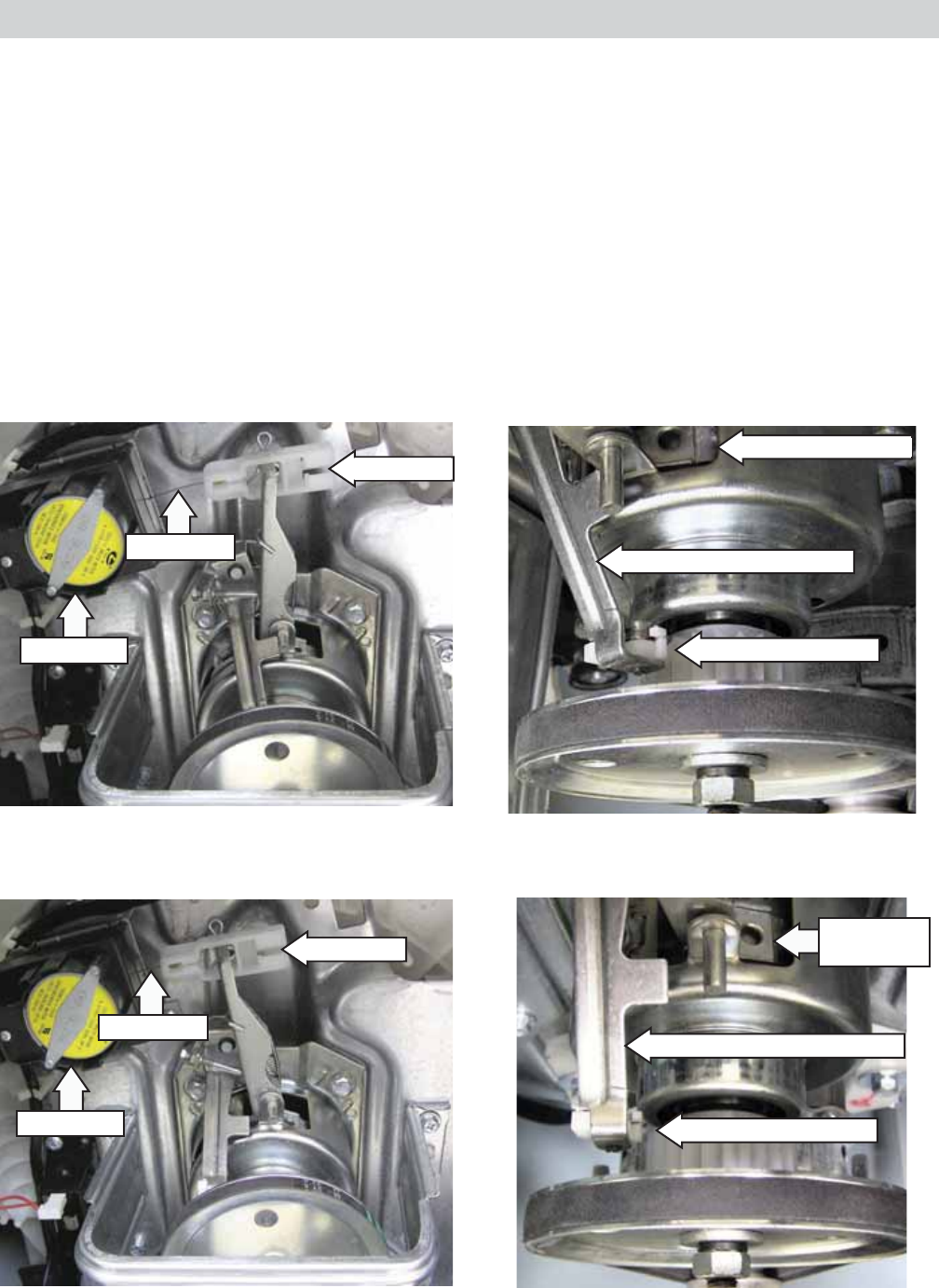
Shaft Assembly and Brake Overview
The shaft assembly consists of the pulsator shaft, wash basket hub, and a brake system.
The shaft assembly operates in 2 distinct modes, spin and agitation.
The pulsator shaft transfers power to the wash system. Motor power is transmitted to the pulsator shaft
from the drive belt to the drive pulley. The drive pulley is attached to one end of the pulsator shaft and the
pulsator is attached to the other. The wash basket hub is fi xed to the washer basket at all times.
Brake action is applied to the wash basket hub located inside the shaft assembly and to a gear located at
the bottom of the assembly. The brake motor extends or retracts a cable connected to the brake arm with
a brake link. The position of the brake arm operates the brake that changes the shaft assembly mode from
spin to agitation. In agitation mode, the wash basket hub is fi xed to the platform and the pulsator shaft
rotates when driven by motor. In spin mode, the pulsator shaft is fi xed to the hub and both rotate together.
Agitation Mode - No 120 VAC applied to brake motor. Brake cable extended and brake system engaged.
Spin Mode - 120 VAC applied to brake motor. Brake cable retracted and brake system disengaged.
Gear Brake Engaged
Brake Arm Engaged Position
Hub Brake Engaged
Brake Arm Disengaged Position
Gear Brake Disengaged
Hub Brake
Disengaged
Brake Motor
Brake Link
Brake Cable
Brake Motor
Brake Cable
Brake Link
– 32 –
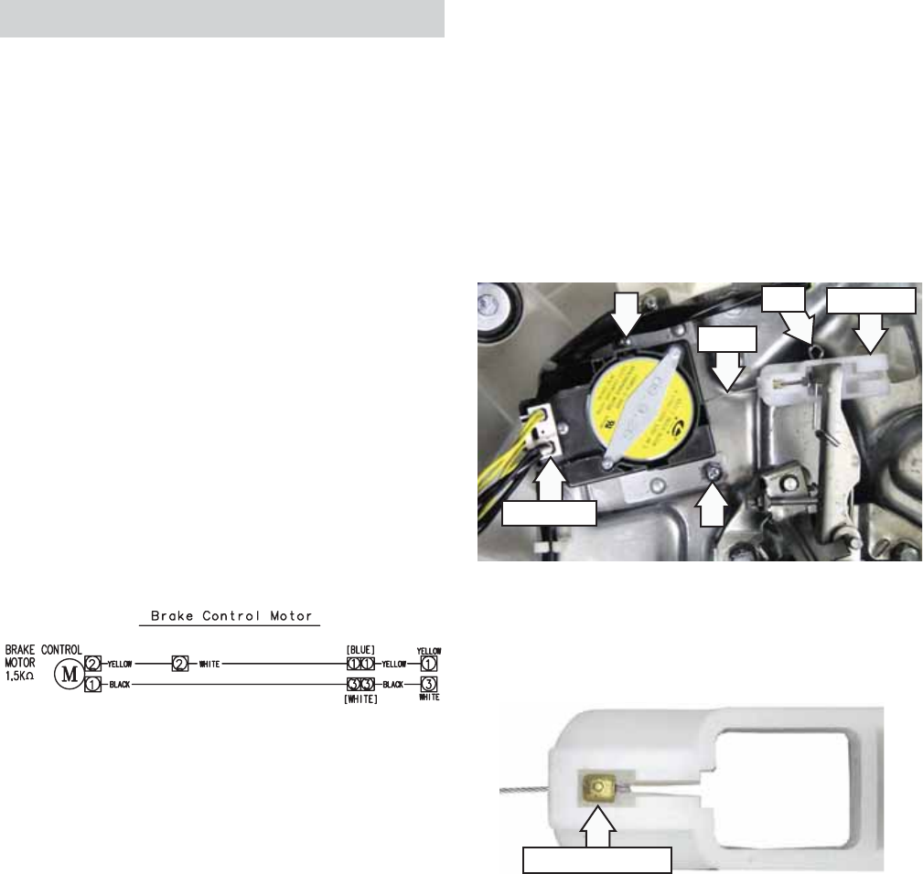
Brake Control Motor
During a normal spin mode that is not interrupted,
the basket will coast to a slow stop without the use
of the brake control motor.
However, if the lid is opened during a spin cycle, the
120 VAC to the brake control motor is stopped, the
gear engaged, and the basket stops immediately.
Diagnostic tip: The brake control motor and pump
are always energized at the same time. Therefore, if
the pump is running, the board is working properly
and supplying 120 VAC to the brake control. An open
brake control motor will allow the pulsator to turn
during spin, but the basket will remain stationary.
This will result in wet clothes at the end of the cycle.
Caution: To access the brake control motor, the
washer can be carefully placed on its front or side.
To prevent scratches to the surface of the washer,
place a towel or blanket on the fl oor.
The brake control motor has an approximate
resistance value of 1.4K Ω.
Disconnect
Cable
Brake Link
Pin
CN3
CN6
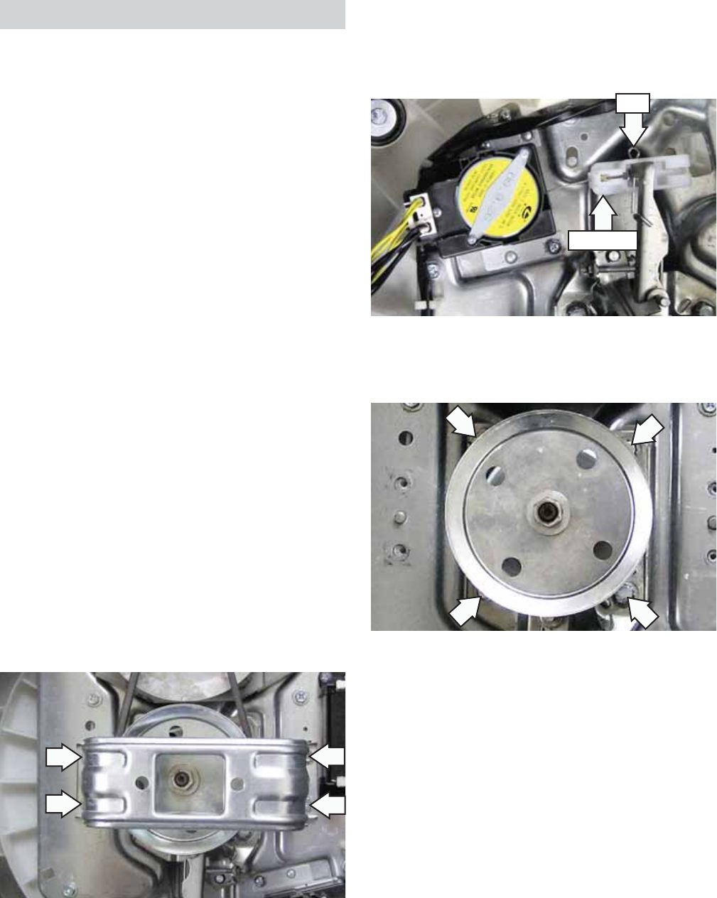
The brake control motor is attached to the platform
with 2 Phillips-head screws.
Note: To prevent the brake cable from dislodging
from the brake link, ensure brake link is installed
with cable stop cutout facing away from the
platform.
Cable Stop Cutout
To remove the brake control motor:
Pull out the pin, then remove the brake link from 1.
the shaft assembly brake lever.
Remove the brake link from the cable. 2.
Disconnect the brake control motor wire 3.
harness.
Remove the 2 Phillips-head screws that attach 4.
the brake control motor to the platform.
– 33 –
Shaft Assembly
Manual Shaft Assembly Checks:
To manually check activation, unplug washer •
and turn the drive pulley to the right. The
activator should easily turn in the same
direction at a ratio of 5.33:1. Turn the pulley to
the left; the activator should easily turn in that
direction.
To check spin, manually move the brake lever •
toward the brake motor to release brake and
engage clutch. Rotate pulley to the right; tub
should rotate to the right.
Note: Failure to operate as described requires shaft
assembly replacement.
The shaft assembly is attached to the platform with
four 13-mm (33/64” SAE equivalent) bolts. To replace
it requires removing the wash basket, belt, and
support saddle.
To remove the shaft assembly:
Remove the wash basket. (See 1. Wash Basket.)
Caution: If the outer tub is not removed as an
assembly, to access the shaft assembly, the
washer can be carefully placed on its front or side.
To prevent scratches to the surface of the washer,
place a towel or blanket on the fl oor.
Remove the four 10-mm (13/32” SAE equivalent) 2.
bolts that attach the support saddle to the
platform.
3. Remove the belt. (See Washing Motor and Belt.)
4. Remove the pin and brake link from the shaft
assembly.
Brake Link
Pin
Pin
Brake Link
5. Remove the four 13-mm bolts that attach the
shaft assembly to the platform.
6. Lift the shaft assembly off the platform.

– 34 –
Error Condition Solution Fault
Water Level Sensor error :
“1E ”
Water level sensor fails to send signal for longer
than 5 seconds.
Press “POWER” button.
No other buttons work. Bad PCB or Pressure Sensor S/W.
Water Supply error :
“FF ”
This occurs when the water supply is not nished
in 1 hour or there is no change in the water level 4
minutes after the water supply has started.
Press “POWER” button or
“START/PAUSE” button.
No other buttons work.
Bad PCB or Pressure Sensor S/W, or
Water-Valve
Drain Pump error :
“dr”
Water level does not decrease to reset point within
15 minutes from draining water from washer.
Press “POWER” button.
No other buttons work. Bad PCB or Pump Moter.
Lid Open error :
“Lo”Lid is opened during wash cycle. Close lid. Bad PCB, Lid S/W, or Unbalance
S/W.
Unbalance S/W error :
“Ub ”
Unbalanced load is sensed three times during a
wash cycle.
Open lid. Rebalance
laundry load and close lid. Bad PCB or Unbalance S/W.
Water Leakage error :
“LE ”
This occurs when it detects that the water level
has fallen below the reset water level for the third
time.
Press “POWER” button. Bad PCB, Pressure sensor S/W,
Pump motor.
Overow error :
“OE ”
This occurs when overow is sensed during
temporary stop, waiting action or spin action,
otherwise overow is sensed three times during a
wash or rinse cycle.
Press “POWER” button. Bad Drain hose, water valve,
Pressure sensor S/W.
Troubleshooting
NOTE: It’s important to note error codes should only be used to help identify components which require
testing. Never replace a part based solely on an error code. The control can generate a false error if the
right conditions exist. Use the code only as a reference and always check the component before replacing.
Error Codes
– 35 –
The washer control has a service test mode that can be utilized by the service technician in order to test
critical components. This test mode will help the service technician to quickly identify failed or improper
operation of certain washer components.
Machine must be in idle mode before entering test. Idle mode occurs when the washer has completed a
cycle.
To enter the service test mode, press simultaneously the OPTIONS, CYCLES, and POWER pads for 1 second.
All LEDs will briefl y illuminate, then the display will alternately show MICOM number and MICOM version
every 2 seconds. Repeated pressing of the START/PAUSE pad initiates specifi c tests. See table below. To exit
test mode press POWER pad.
Service Test Mode
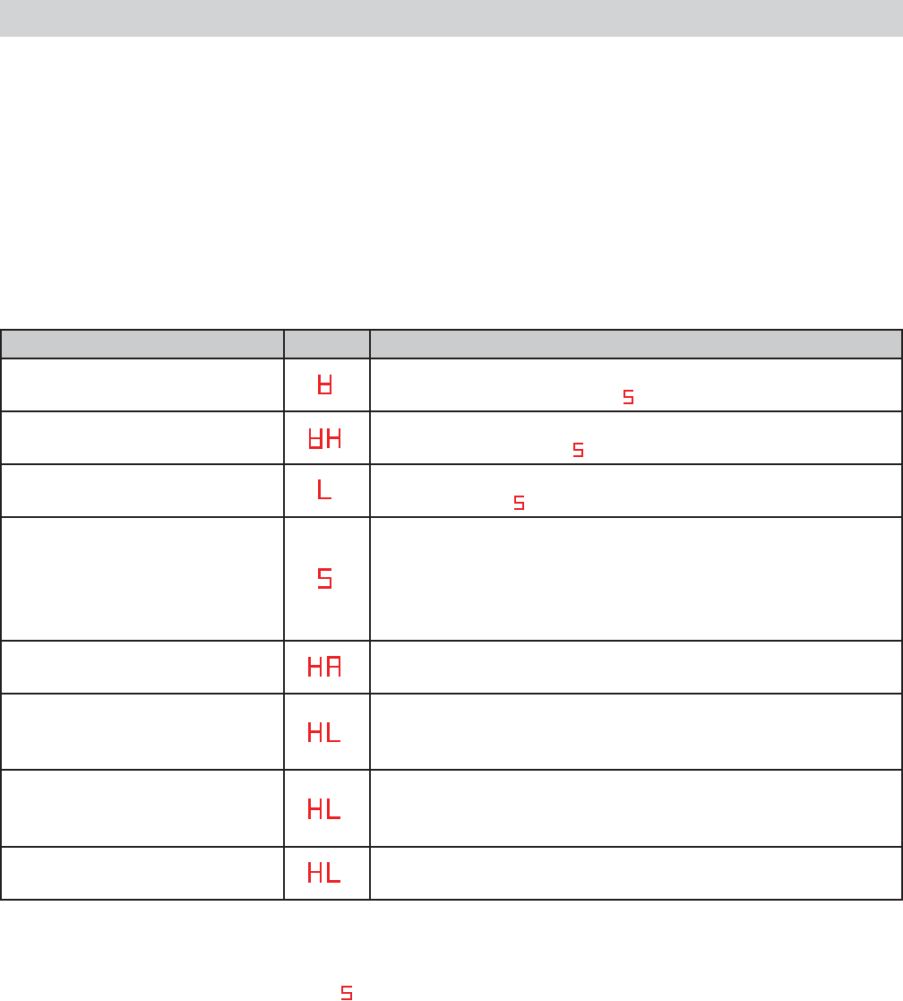
SERVICE MODE TEST DISPLAY ACTION
Water level sensor-test #1 Fills to extra large level, starts wash. To pump out, repeatedly
press START/PAUSE pad until appears in the display.
Water level sensor-test #2 Fills to small level, starts wash. To pump out, repeatedly press
START/PAUSE pad until appears in the display.
Water level sensor-test #3 Fills to extra large level. To pump out, repeatedly press START/
PAUSE pad until appears in the display.
Drain and spin, lid open, and
unbalance switch test
Starts drain and initiates spin. After 4 failed spin attempts, 3E
error, is displayed and error sound is audible. If 3E appears
and motor is not operating, replace it. If 3E appears and the
motor is operating properly, replace the PCB. If washer drains
and spins; lid switch, unbalance switch, and motor OK.
Weight sensing test (See Note) Weight sensing begins, then display shows weight sensing
data.
Water valve test Press TEMP pad repeatedly to test cool, rinse, and hot water
functionality: First press = Cool, Second press = Rinse, Third
press = Hot, Fourth press = Off.
Motor test Press LOAD pad repeatedly to test motor/pulsator rotation:
First press = Motor rotates pulsator CW, Second press = Off,
Third press = Motor rotates pulsator CCW, Fourth press =Off.
Drain pump test Press OPTIONS pad repeatedly to test drain pump: First press
= Pump out, Second press = Off
Note: Before weight sensing test is initiated, make sure that no water remains in the washer. If water is
remaining in the washer, inaccurate data will be displayed, or the test will not proceed. To pump out,
repeatedly press START/PAUSE pad until appears in the display.
With no clothing in the tub, when placed in the HA test, the following occurs:
Weight sensing begins.1.
Weight sensing ends, only the appropriate load light stays lit, and the display shows corresponding 2.
weight sensing data.
The load light will indicate load size. Adding additional dry clothing, (not water( will decrease the data number
as weight is increased. Data readouts are approximate: Extra Small = 97, Small = 89-96, Medium = 82-88,
Large = 76-81, and Extra Large = 75 or lower.
If the Soak light remains lit, 100 will be added to the display number.
– 36 –
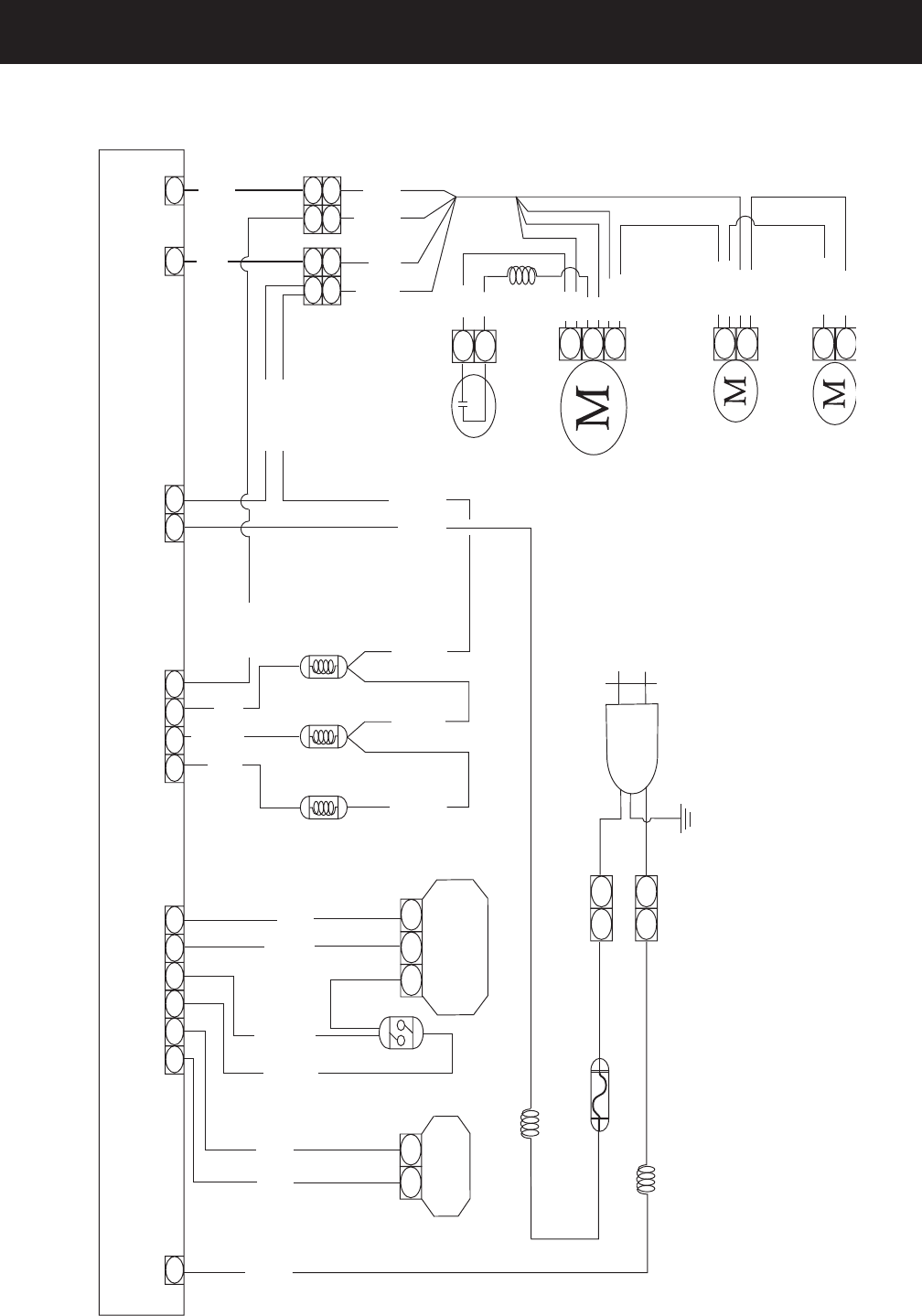
Schematic
1
BLACK
[BLACK]
EARTH
DRAIN PUMP
MOTOR
11.77
BRAKE CONTROL
MOTOR
1.5K7
WASHING MOTOR
CONDENSOR
COOL WATER
RINSE WATER
UNBALANCE S/W
HOT WATER
POWER
BLACKBLACK
COIL 2
DOOR S/W PRESSURE
SENSOR
YELLOW
BLACK
YELLOW
[BLUE] [WHITE]
COIL 1
FUSE
AC25OV / 12A [WHITE]
WHITEWHITE
WHITE YELLOW RED
RED
BLUE
RED
WHITE
WHITE
RED
BROWN
GRAY
PINK
VIOLET
ORANGE
SKYBLU
BLUE
BLUE
BLACK
YELLOW
YELLOW
YELLOW
YELLOW
BLUE
BLACK
WHITE
111
1
1
1
3
2
2
1
1
1
1
1
1
3
3
2
3
4
6
5
2
4
11
5
10
P C B C O N T R O L
3
3
1
1
YELLOW
YELLOW
YELLOW
RED
RED
BLUE
1 2
1 1
1 1
2 1 3
RED
BLUE
BLUE
YELLOW
YELLOW
BLACK
BLACK
BLACK
CN1
CN2 CN3 CN4
CN5
CN6
WHITE
– 37 –
Warranty
GE Washer Warranty. (For customers in the U.S.A.)
For The Period Of: We Will Replace:
All warranty service provided by our Factory Service Centers,
or an authorized Customer Care®technician. To schedule service,
on-line, visit us at ge.com, or call 800.GE.CARES (800.432.2737).
Please have serial number and model number availa ble when
calling for service.
This warranty is extended to the original purchaser and any succeeding owner for products purchased for home use
within the USA. If the product is located in an area where service by a GE Authorized Servicer is not available, you may
be responsible for a trip charge or you may be required to bring the product to an Authorized GE Service location for
service. In Alaska, the warranty excludes the cost of shipping or service calls to your home.
Some states do not allow the exclusion or limitation of incidental or consequential damages. This warranty gives you
specific legal rights, and you may also have other rights which vary from state to state. To know what your legal rights
are, consult your local or state consumer affairs office or your state’s Attorney General.
■Service trips to your home to teach you how to use
the product.
■Improper installation, delivery or maintenance.
■Failure of the product if it is abused, misused, or used for
other than the intended purpose or used commercially.
■Damage after delivery.
■Replacement of house fuses or resetting of circuit
breakers.
■Damage to the product caused by accident, fire, floods
or acts of God.
■Incidental or consequential damage caused by possible
defects with this appliance.
■Product not accessible to provide required service.
What Is Not Covered (in the United States):
Warrantor: General Electric Company. Louisville, KY 40225
Staple your receipt here.
Proof of the original purchase
date is needed to obtain service
under the warranty.
One Year Any part of the washer which fails due to a defect in materials or workmanship. During this
From the date of the limited one-year warranty, GE will also provide, free of charge, all labor and related service
original purchase costs to replace the defective part.
EXCLUSION OF IMPLIED WARRANTIES—Your sole and exclusive remedy is product repair as provided in this Limited
Warranty. Any implied warranties, including the implied warranties of merchantability or fitness for a particular
purpose, are limited to one year or the shortest period allowed by law.
