Monogram Dishwasher GE ZBD6800 6890 31 9116
2013-04-09
: Pdf Ge Zbd6800-6890 - 31-9116 GE ZBD6800-6890 - 31-9116 GE, Camco, Hotpoint, Mofat
Open the PDF directly: View PDF ![]() .
.
Page Count: 26
PUB # 31-9116 03/04
MODEL SERIES:
TECHNICAL SERVICE GUIDE
Top Control Monogram
Dishwashers
ZBD6800K
ZBD6880K
ZBD6890K
GE Consumer & Industrial

– 2 –
IMPORTANT SAFETY NOTICE
The information in this service guide is intended for use by
individuals possessing adequate backgrounds of electrical,
electronic, and mechanical experience. Any attempt to repair a
major ap pli ance may result in personal injury and property
damage. The man u fac tur er or seller cannot be responsible for the
in ter pre ta tion of this in for ma tion, nor can it assume any liability in
connection with its use.
WARNING
To avoid personal injury, disconnect power before ser vic ing this
prod uct. If electrical power is required for di ag no sis or test pur pos es,
disconnect the power immediately after per form ing the nec es sary
checks.
RECONNECT ALL GROUNDING DEVICES
If grounding wires, screws, straps, clips, nuts, or washers used to
complete a path to ground are removed for service, they must be
returned to their original position and properly fastened.
GE Consumer & Industrial
Technical Service Guide
Copyright © 2004
All rights reserved. This service guide may not be reproduced in whole or in part
in any form without written permission from the General Electric Com pa ny.
– 3 –
Active Vent .......................................................................................................................20
Circulation Pump and Motor ............................................................................................12
Component Locator Views .................................................................................................8
Components ....................................................................................................................10
Control Features ................................................................................................................5
Control Module ................................................................................................................18
Demo Mode .....................................................................................................................13
Control Module Board ......................................................................................................18
Detergent/Rinse Module .................................................................................................19
Door Interlock Switch ......................................................................................................19
Door Panel ......................................................................................................................17
Drain System ...................................................................................................................15
Factory Test Mode ...........................................................................................................22
Fan ...................................................................................................................................20
Fill Funnel ........................................................................................................................11
Heating Element ..............................................................................................................13
Lower Spray Arm, Fine Filter, and Inlet Cover .................................................................11
Main Conduit ...................................................................................................................11
Membrane Keypad ..........................................................................................................17
Middle Spray Arm ............................................................................................................10
Nomenclature ...................................................................................................................4
Schematic ........................................................................................................................25
Service Mode ...................................................................................................................21
Strip Circuits ....................................................................................................................24
Transorb ..........................................................................................................................16
Troubleshooting ..............................................................................................................23
Turbidity Sensor ...............................................................................................................14
Upper Spray Arm .............................................................................................................11
Using the Dishwasher with the Upper Rack Removed ....................................................10
Warranty .........................................................................................................................26
Wash Cycles ....................................................................................................................12
Water Valve and Flood Switch ........................................................................................15
Water Valve Test .............................................................................................................16
Table of Contents
– 4 –
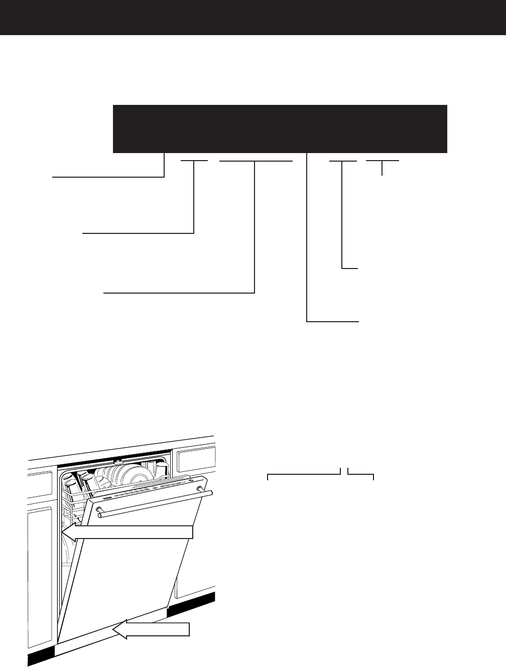
Model Designator
Designates features – the higher
the number, the more features.
The letter des ig nat ing
the year re peats every
12 years.
Example:
T - 1974
T - 1986
T - 1998
Z B D 6 8 0 0 J 0 0 B B
Brand
Z = Monogram
Product Type
DB = Built-In Dishwasher
Exterior Color
BB = Black
CC = Bisque
SS = Stainless Steel
WW = White
II = Integrated*
Model Year Designator
Engineering Model Suffi x
Model Number
The fi rst two characters of the serial number
identify the month and year of manufacture.
Example: AG123456S = January, 2004
A - JAN 2005 - H
D - FEB 2004 - G
F - MAR 2003 - F
G - APR 2002 - D
H - MAY 2001 - A
L - JUN 2000 - Z
M - JUL 1999 - V
R - AUG 1998 - T
S - SEP 1997 - S
T - OCT 1996 - R
V - NOV 1995 - M
Z - DEC 1994 - L
Note: The service information sheet is located
un der the control panel.
Serial Number
The model number and serial number are located inside the door jam. The mini-manual is located behind
the toe-plate.
*Note: The exterior color,
II = Integrated, requires a
panel kit.
Nomenclature
Mini Manual
Model and Serial Number
– 5 –
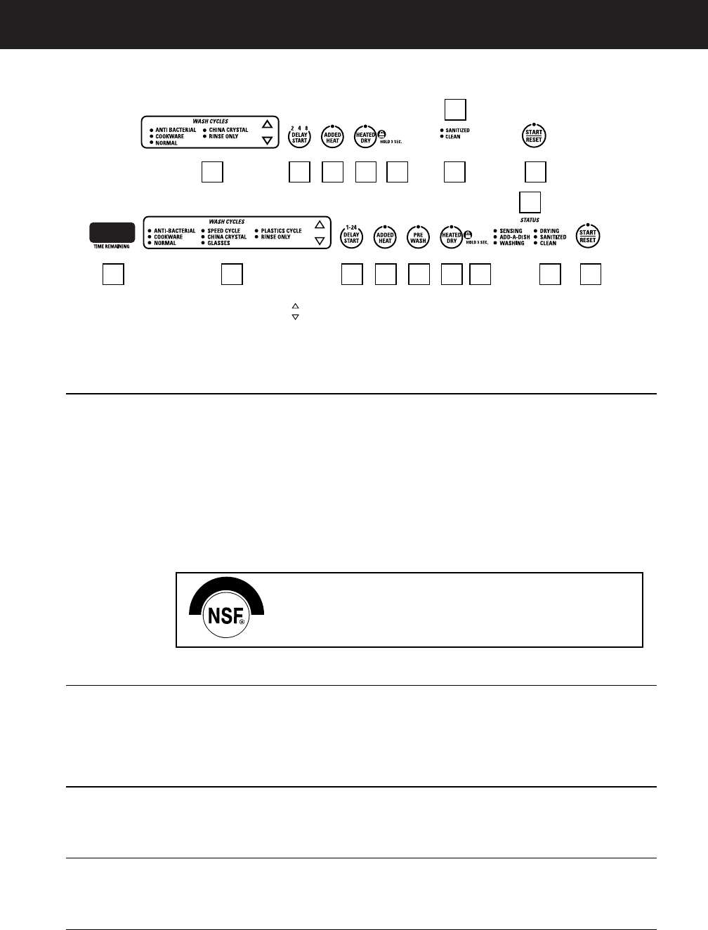
Control Features
1. Wash Cycles Use the arrow pads to scroll through the wash cycles. The light above or next to
the selected pad will be ON to indicate which WASH CYCLE has been selected.
NOTE: This dishwasher is equipped with an ExtraClean™Sensor with automatic
temperature control; therefore, cycle length and time may vary depending on
soil (heavy, medium, light) and temperature conditions.
ANTI Heavy 10.0 gallons, 93 minutes
BACTERIAL Medium 8.6 gallons, 90 minutes
Light 7.2 gallons, 90 minutes
This cycle raises the water temperature in the final rinse to sanitize your
dishware. The cycle length will vary depending on the temperature of your inlet
water.
NOTE: The Anti-Bacterial cycle is monitored for sanitization requirements.
If the cycle is interrupted during or after the main wash portion or if the
incoming water temperature is so low that adequate water heating cannot
be achieved, the sanitizing conditions may not be met. In these cases, the
sanitized light will not illuminate at the end of the cycle.
NOTE: NSF certified residential dishwashers are not intended for licensed food
establishments.
COOKWARE Heavy 11.4 gallons, 95 minutes
Medium 10.0 gallons, 71 minutes
Light 10.0 gallons, 66 minutes
This cycle is meant for heavily soiled dishes or cookware with dried-on or
baked-on soils. This cycle may not remove burned-on foods. Everyday dishes are
safe to be used in this cycle.
NORMAL Heavy 9.9 gallons, 74 minutes
Medium 7.0 gallons, 61 minutes
Light 5.6 gallons, 48 minutes
This cycle is for medium/heavily soiled dishes and glassware.
SPEED CYCLE Heavy 9.3 gallons, 36 minutes
(on some models)
Medium 7.2 gallons, 36 minutes
Light 5.7 gallons, 33 minutes
This cycle is for everyday dishes and glassware.
CHINA Heavy 10.0 gallons, 49 minutes
CRYSTAL Medium 7.2 gallons, 36 minutes
Light 7.2 gallons, 36 minutes
This cycle is for lightly soiled china and crystal.
8 1 432 5 6
7
910
1 32 5 6
7
910
NSF INTERNATIONAL
Meets NSF Standard 184 Sanitization and Cleaning
performance of household spray-type dishwashers.
R
E
S
I
D
E
N
T
I
A
L
ZBD6890
ZBD6800 and ZBD6880

– 6 –
GLASSES Heavy 10.0 gal., 45 min.
(on some models) Medium 7.2 gal., 33 min.
Light 7.2 gal., 32 min.
This cycle is specifically designed for glasses.
PLASTICS Heavy 9.9 gal., 119 min.
CYCLE Medium 7.0 gal., 106 min.
(on some models) Light 5.6 gal., 93 min.
This cycle is specifically designed to reduce the risk of melting plastic items
and improve plastic drying for dishwasher safe plastic items.
RINSE ONLY Heavy 2.9 gallons, 7 minutes
Light 1.4 gallons, 3 minutes
For rinsing partial loads that will be washed later. Do not use detergent with
this cycle.
2. DELAY START —This option will allow you to delay the start time of any wash cycle for up to
24 hours (depending on model).
• Select the delay start time you want by pressing the DELAY START pad.
Multiple or continuous pressing will increment the delay hours. Select the
number of hours you want to delay the start of the cycle. Then press
START/RESET.
• After closing the door, the machine will count down and automatically start
at the correct time.
NOTE: To cancel the DELAY START selection before the cycle begins, press
the DELAY START pad until the display is blank. Pressing START/RESET will
not cancel delay hours.
3. ADDED HEAT — When selected, the cycle will run longer with heating elements on to improve
both wash and dry performance.
NOTE: Cannot be selected with RINSE ONLY cycle.
4. PRE WASH — For use with heavily soilded and/or dried-on, baked-on soils. This option
(on some models) MUST be selected PRIOR to starting the cycle. This option adds 16 minutes
to the cycle time.
NOTE: Cannot be selected with RINSE ONLY cycle.
5. HEATED — When selected, turns the drying heater and fan on for fast
DRY drying. This option will extend the cycle time by 30 minutes for
the ANTI-BACTERIAL cycle, 38 minutes for the NORMAL cycle and
COOKWARE cycle, 8 minutes for the SPEED cycle, 15 minutes for the
PLASTICS cycle and 30 minutes for all other cycles. When this is NOT
selected, the fan will turn on to dry your dishes without added heat—and
energy is saved.
NOTE: Cannot be selected with RINSE ONLY cycle.
6. LOCK — You can lock the controls to prevent any selections from being made. Or you
can lock the controls after you have started a cycle.
Children cannot accidentally start the dishwasher by touching pads with this
option selected.
To lock the dishwasher, press and hold the HEATED DRY pad for 3 seconds.
To unlock the dishwasher controls, press and hold the HEATED DRY pad for
3 seconds. The light above the LOCK will turn off.
(Control Features Continued)

– 7 –
7. Status Indicator Lights
(indicators vary by model)
The Status display tells you what is happening while the dishwasher is in
operation and may flash, indicating a malfunction. The lights will come ON,
indicating the sequence of the dishwasher operation.
SENSING Displayed while the ExtraClean™Sensor is measuring the amount of soil and
temperature of water. The dishwasher will adjust the selected cycle to achieve
optimal performance.
ADD-A-DISH Displayed during prewash indicating that dishes added now will still be
cleaned.
WASHING Displayed during prewash, main wash and rinse periods.
DRYING Displayed during HEATED DRY.
SANITIZED Displayed when cycle has met sanitization conditions.
CLEAN Displayed when a wash cycle is complete and enhancements are complete.
8. Time Remaining Display (on some models)
During operation, the display shows the minutes remaining until the cycle is complete. The
display may adjust the remaining time while the Sensing light is on. During a delay start, the
display will show hours of time remaining until the cycle starts.
9. START/RESET
START — After selecting the cycle and desired enhancements, press the START/RESET
pad to ready the dishwasher to begin the cycle. Close the door to start the
cycle or begin the DELAY START countdown. When the cycle starts, the water
fill begins and approximately 60 seconds later the wash action begins.
The dishwasher will always display your last selection and enhancements. If
you don’t want to change the settings, simply press the START/RESET pad to
ready the dishwasher and close the door to begin the cycle.
NOTE: If the START/RESET light is flashing, the cycle has been
interrupted by pressing the START/RESET pad. Light will quit flashing
after the dishwasher automatically drains out the water.
Also, if a power failure occurs NORMAL and HEATED DRY will automatically
be programmed. Make any new selections and press the START/RESET pad
to begin the new cycle.
RESET — Open the door slowly to prevent splash-out. Press the START/RESET pad
to cancel the cycle and close the door. Dishwasher will pump out and turn off
after 70 seconds.
NOTE: If the START/RESET light is flashing, close the door until the water
pumps out (this takes approximately 70 seconds) and the light stops flashing.
When the light stops flashing, the dishwasher can be reprogrammed and
restarted.
10. Clean — The CLEAN light is illuminated and a double beep will sound when the
selected cycle and enhancements are complete. You may remove the dishes
at any time. Note the high-efficiency fan will run quietly for 30 minutes to 4
hours (depending on selected cycle) after the CLEAN light is illuminated to
continue drying the dishes. This can be interrupted by opening the door and
pressing any keypad.
NOTE: To turn off the double beep indicator (or re-activate it if it was
previously disengaged), press the HEATED DRY pad 5 times within 3
seconds. A triple beep will sound to indicate the end-of-cycle beep option
has been toggled.
(Control Features Continued)
– 8 –
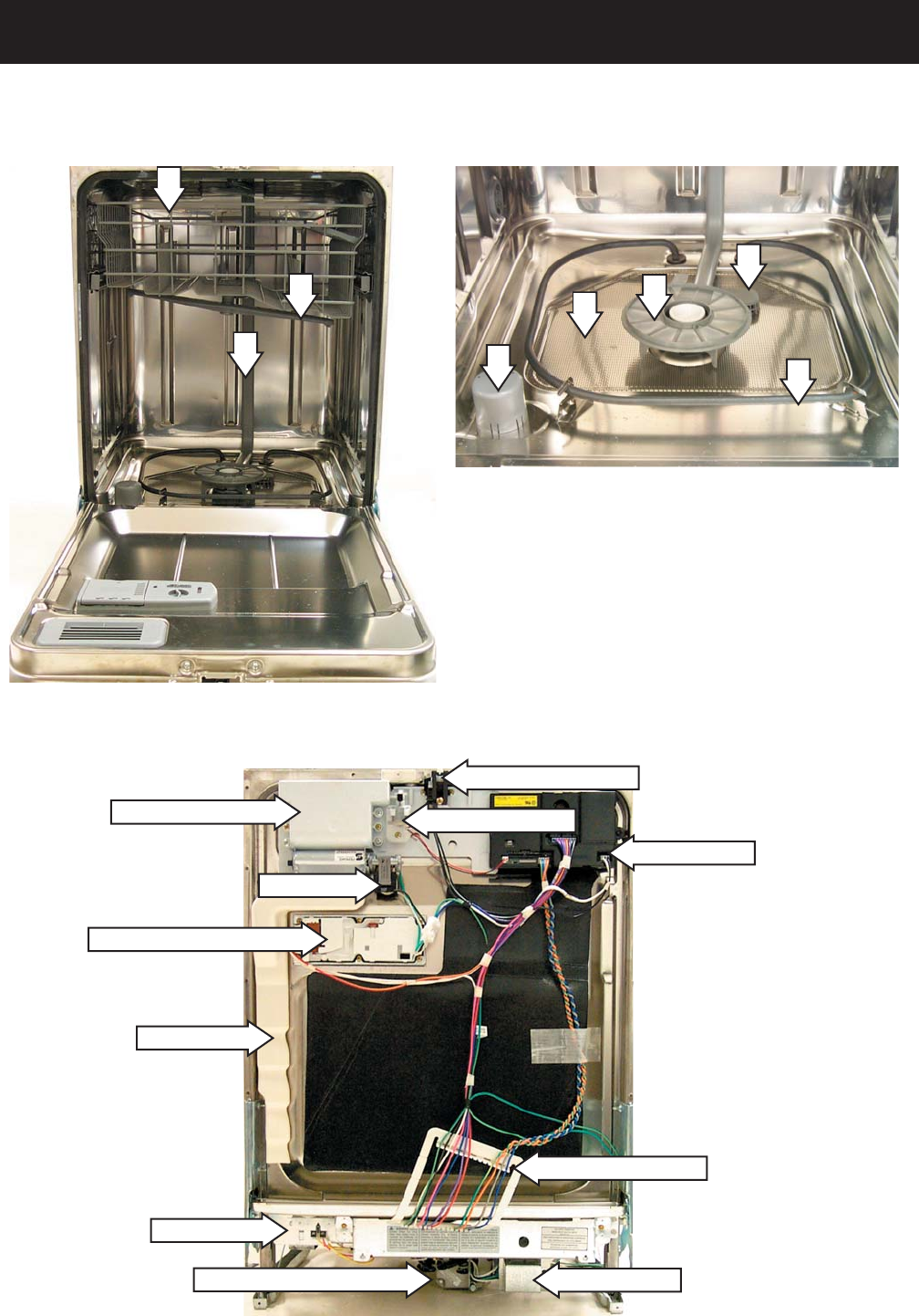
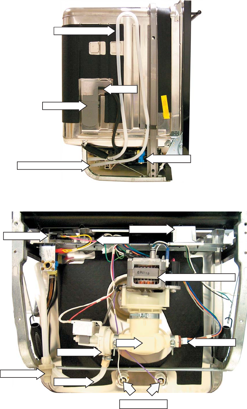
Component Locator Views
Door View (Front Panel Removed)
Inside Cabinet View
1 - Upper Spray Arm
2 - Middle Spray Arm
3 - Main Conduit
4 - Hub (lower spray arm
removed)
1
2
3
Fan Conduit
Fan Motor
Circulation Pump Motor Junction Box
Control Module
Flood Switch
Detergent Rinse Module
Vent & Fan Assembly
Door Interlock Switch
5 - Filter Screen
6 - Heating Element
7 - Float
8 - Inlet Cover
7
4
6
5
8
Vent Louver Motor
Wire Harness Loom
Note: The wire
harness loom is
used to help the wire
harness make the
transition over the
tub trough lip. Make
certain loom and wires
are replaced correctly
to prevent wires from
being pinched.
– 9 –
Fill Funnel
Bottom View
Left Side View
Front of Dish wash er
Rear of Dish wash er
Water Valve
Fill Hose
Drain Tube Assembly
Drain Line Check Valve
Junction Box
Sump
Drain Pump
Drain Line
Circulation Pump Motor
Turbidity Sensor
Transorb
Flood Switch
Check Valve
Heating Element
– 10 –
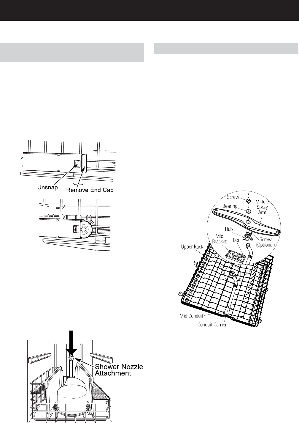
Middle Spray Arm
Check the holes in the spray arm for bits of china,
seeds, and other foreign matter. Also, check the
spray arm for rotation.
Removal and Replacement
1. Pull the upper rack all the way out.
2. Remove the plastic screw on the bottom of
the middle spray wash arm. This will allow
the middle spray arm and bearing to be
removed.
Note: Install middle spray wash arm with spray
jets facing the upper rack. Place bearing between
spray arm screw and bottom of the middle arm.
Components
Note: If the upper rack experiences poor cleaning
problems, ensure the middle spray wash arm
is turning freely. If not, disassemble the middle
spray wash arm and clean the bearing surface,
then reassemble.
Using the Dishwasher with the Upper
Rack Removed
1. Unsnap and remove the end cap on each side
of the rails.
2. Pull the rack straight out and off the rails.
3. Replace the end caps.
4. Push the rails all the way back into the
dishwasher.
5. Slide the shower nozzle attachment over the
spout.
6. The dishwasher is now ready for use.
Note: Always use the shower nozzle when the
upper rack is removed.
– 11 –
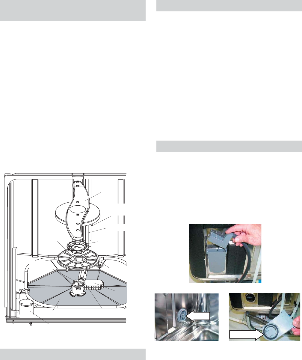
Fill Funnel
The top section of the fi ll funnel separates from
the main body. The fi ll funnel body is held in place
by a nut (located on the inside of the dishwasher).
Rotate the nut counterclockwise to remove the
main body. There is an O-ring seal be tween the
fi ll funnel and dish wash er tub. Make certain the
O-ring is fully seated when reinstalling.
Main Conduit
The main conduit supplies water to the middle
and upper spray wash arms.
Removal and Replacement
1. Pull the upper rack out.
2. Push the tab on the outer slide cap in and
remove the slide cap.
3. Remove the upper basket.
4. Release the bottom conduit tab.
5. Release the 2 center conduit tabs, then
remove the main conduit.
Upper Spray Arm
Check the holes in spray wash arm for bits of
china, seeds, and other foreign matter. Also,
check the spray arm for rotation.
To remove the upper spray wash arm, remove the
upper basket (See Middle Spray Wash Arm), then
remove the screw and upper spray wash arm.
Lower Spray Arm, Fine Filter, and Inlet
Cover
Check the holes in the spray arm for bits of china,
seeds, and other foreign matter. Also check the
spray arm for rotation. If soil is present, clean fi ne
fi lter screen.
The lower spray arm can be removed by gently
lifting and rotating it coun ter clock wise.
The nut hub can be removed by rotating it
counterclockwise.
Caution: Use care to avoid breaking the clip on
the hub when removing the main conduit from
hub.
Note: When installing the fi ne fi lter, make sure
the drain port of the fi lter is engaged with the
drain for the fi ne fi lter.
O-ring
Nut
Lower
Spray Arm
Nut Hub
Cover Inlet
Hub
Float Dome
Coarse Filter
Fine Filter
Drain Port
Fine Filter
Assembly
Main Conduit
Mounting Scre
w
Main Conduit
Drain For
Fine Filter
Main Conduit
Tab
– 12 –
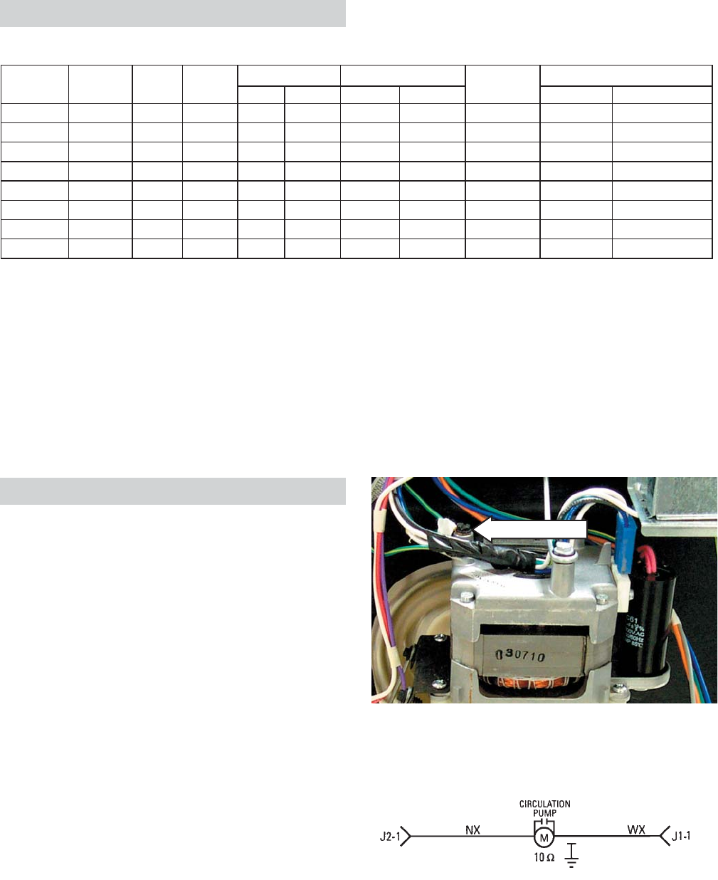
Circulation Pump and Motor
The dishwasher must be removed from its
in stal la tion to gain access to the circulation pump
and motor. The circulation pump can be activated
using Service Mode. Refer to sche mat ic or strip
circuit for motor resistance value.
Before removing the circulation pump, remove
the water from the sump.
It is important to remember the motor does not
start immediately when the dishwasher cycle has
started. If the motor hums, but will not start, make
certain the pump impeller is free from obstruction
and the motor shaft can turn freely.
The terminals on the induction motor are labeled
L1 and N. The motor is thermally protected
(internally) through the L1 side. The wiring
connector is blue to match the wire leading to
the motor. It is designed to fi t only one way on
the terminals. Make certain the connector is fully
seated when installing.
Note: It is extremely important that the self-
tapping grounding screw is tightened securely
when reinstalling the circulation pump.
Ground Screw
Circulation Pump and Motor Strip Circuit
MIN MAX MIN MAX HEATED DRY W/O HEATED DRY
Normal Wash 3 1 3 32 88 1302150238 120 240
Speed Wash 3 1 2 19 26 125315038120 240
Glasses 3 1 3 26 39 1103130330 120 240
China Crystal 3 1 3 30 52 1103130330 120 240
Pots & Pans 4 1 3 44 108 1403150338 120 240
Sani Wash 3 1 3 21 100 130315838+154120 240
Rinse Only 0 0 2 2 2 80 158 Not An Option Not An Option 240
Plastics 3 1 3 39 88 1302140245/605120 240
Time is in minutes
Temperature is in degrees Fahrenheit
1.) Cycle times do not include water fill and drain
2.) Heater on in main wash and final rinse
3.) Heater on in all pre-washes, main wash and all rinses
4.) 8 minutes heated dry and 15 minutes cool down
5.) 45 minutes without heated dry, 60 minutes with heated dry
6.) Fan running time after cycle has completed
FAN ON TIME6
WASH TEMPERATURE
WASH TIME1
CYCLE
MAX # OF
PRE-WASH
CYCLES
WASH
CYCLE
MAX
#
RINSE
CYCLES
HEATED
DRY TIME
Wash Cycles

– 13 –
Heating Element
The heating element can be activated using
Service Mode.
The dual-wattage heating element produces 875
watts during wash, to help heat the water, and
an effective wattage due to cycling of 700 watts
during the dry cycle.
It is normal for the heating element to cycle during
HEATED DRY. The control energizes the heating
element continuously for the fi rst 6 minutes, then
cycles the heating element ON for 60 seconds,
then OFF for 60 seconds for the remainder of the
HEATED DRY cycle.
Selecting ADDED HEAT will energize the heater
for the entire time during the last prewash cycle
and the fi nal rinse cycle. Circulation time during
the fi nal rinse is increased 2.8 times the normal
with this option. If selected after the wash cycle
has started, the feature will not take effect until
the beginning of the next fi ll. This option is not
available for the RINSE ONLY cycle.
Water inlet temperature must be at least 120°F
for proper drying. Low water inlet tem per a ture
will pre vent proper con vec tion air move ment and
increase drying time sub stan tial ly.
If the problem is that the dishes are not drying
cor rect ly, don’t overlook the rinse agent. A rinse
agent will improve the water sheeting action and
drying performance.
It is normal for the stainless steel tub and the
inner door panel to retain water droplets even
though the dishes are dry.
The heating element nuts are located on the
underside of the washer, near the back. Ample
force is required to remove the nuts. Removing
the dishwasher from installation may be required.
Tub
Nut
Heating Element
Support
Heating
Element
Heater
Grommet
Heating Element Strip Circuit
J2-3
J2-4
VX
VX
J1-1
Heating Element (17 Ohms)
WX
Demo Mode
• Demo mode is entered by pressing the down
arrow and ADDED HEAT pads simultaneously
for 5 seconds.
• When entered, the NORMAL and ADDED
HEAT LEDs blink for 3 seconds, and the
active vent will close.
• Pressing a pad will light the corresponding
LED.
• Pressing the START/RESET pad will
activate the main pump for 20 seconds, and
each cycle LED will be lit in sequence for 3
seconds (left to right).
• On 3-digit display models, the display will
sequence 999, 888, 777, 666, 555, etc.,
before running the main pump.
• The cycle will end after the main pump stops.
The drain cycle will not be energized.
• To exit the demo mode, the dishwasher must
be disconnected from power.
– 14 –
Note: When replacing the turbidity sensor, always
run the Factory Test Mode to calibrate the turbidity
sensor to the control board.
When installing the turbidity sensor, align the key
on the sensor with the keyway on the sump.
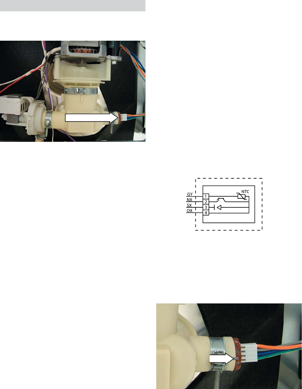
Turbidity Sensor
The turbidity sensor is located on the side of the
sump.
Note: If the turbidity sensor circuit fails to open or
is shorted, the sensing LED on the control panel
will not light, and the unit will operate for the
maximum amount of time, using the maximum
number of wash and rinse fi lls for the selected
cycle.
The turbidity sensor also contains the thermistor
for automatic temperature control.
The thermistor’s resistance has a negative
temperature coeffi cient. As the temperature
increases, the resistance goes down. At 75°F, the
resistance is approximately 9.9K Ω. At 140°F, the
resistance is approximately 2.8K Ω.
Turbidity Sensor Test
The Service Mode is the most accurate way to
test the turbidity sensor circuit. The turbidity
sensor circuit con tains the control module, wiring,
and the tur bid i ty sensor.
The turbidity sensor measures the amount of
suspended particles in the wash water in the
sump. The control sends the turbidity sensor a
pulse width modulated 5-volt signal for calibration
and usage during operation.
The control then receives an analog signal of
the sensed turbidity, which is processed by the
microprocessor.
The baseline reading is taken during the fi rst fi ll
when the sump water level is between the 1/4- to
3/8-in. gap between the LED transmitter and the
receptor. Successive tur bid i ty mea sure ments
are sup plied to the control module and used to
de ter mine whether any prewash or rinse cycles
can be skipped. The sensing LED is on during all
prewash cycles and during the fi nal rinse.
Decisions are based on a com par i son of clean
water mea sure ments at the beginning of the fi rst
fi ll, mea sure ments taken at selected fi lls, and
water tem per a ture. By measuring the turbidity
level, the control module can conserve energy
on lightly soiled loads by skipping un nec es sary
cycles.
Turbidity Sensor
Key
– 15 –
Note: To prevent leaks after installation, ensure
that hose-to-valve connection is good and that
clamp is in place.
Water Valve and Flood Switch
The water valve is a 120 VAC solenoid valve that
is switched on/off by the control module. The
fl ood switch acts as a safety switch ONLY and
does not control normal operation of the water
valve. The fl ood switch opens the L1 side of the
water valve circuit.
The switch is normally open. The weight of the
fl ood switch fl oat holds the switch closed. The
fl ood switch will not stop the fl ow of water if the
valve sticks open from a mechanical failure.
The water valve can be replaced with the
dish wash er installed.
WARNING: Disconnect power to dishwasher
before servicing water valve and fl ood switch.
The water valve is secured to the frame by 2 hex
head screws. (Photo is shown with fl ood switch
removed.)
Water Valve
Flood Switch
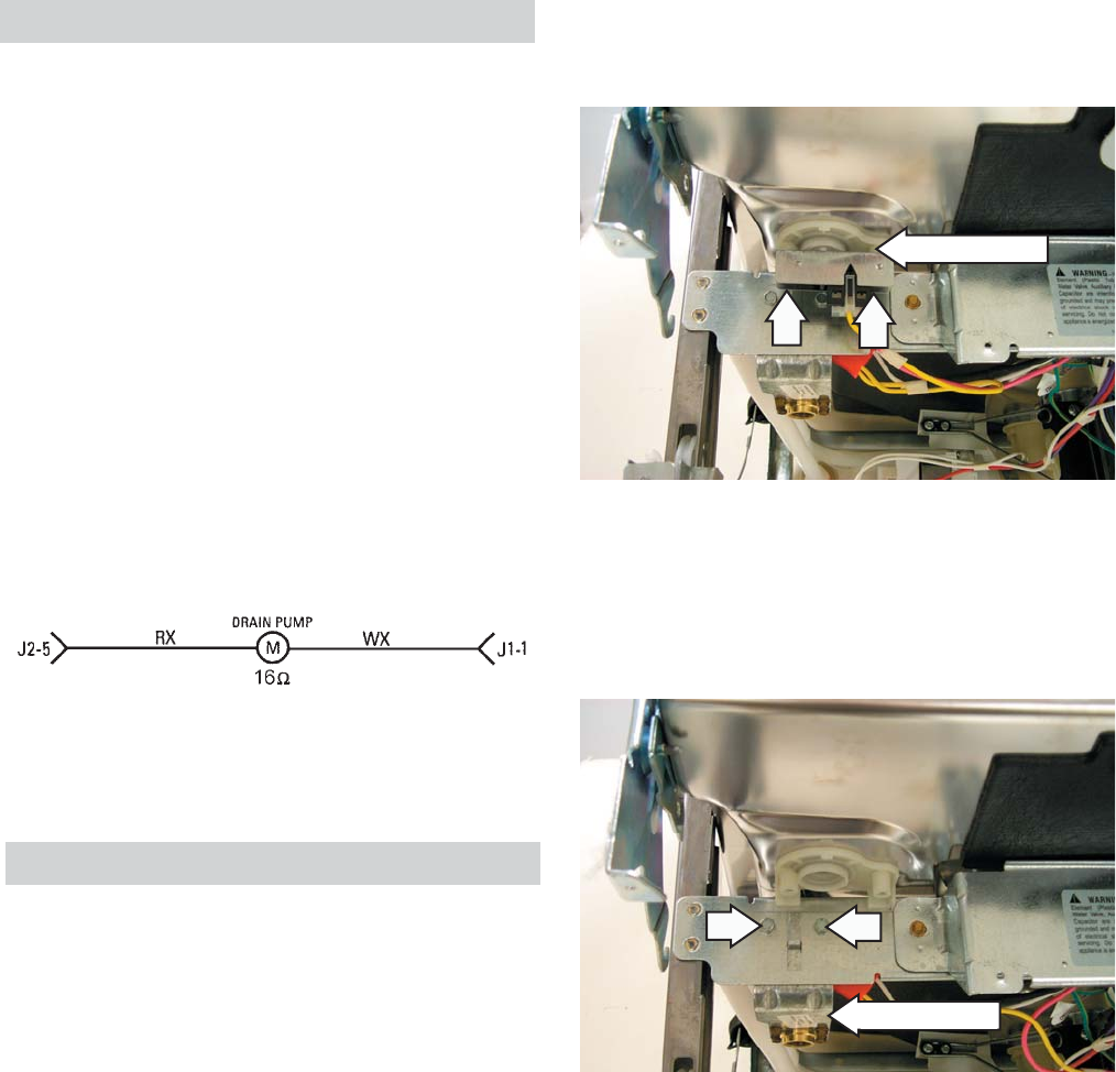
Drain System
The drain system consists of the following
com po nents:
• Auxiliary drain pump (includes motor and one-
way check valve)
• Drain tube
• Check valve (in line with drain tube)
• Drain hose
The inlet cover prevents large particles from
entering the sump. Water entering the drain pump
is not fi ltered by the fi ne fi lter (metal) or by the
sump fi lter (plastic). The drain pump is mounted
on the sump and contains a one-way check
valve. The drain pump is controlled by the control
module and can be activated using Service Mode.
The fl ood switch is held in place by 2 Phillips
head screws.
Auxilary Drain Pump strip Circuit
The drain pump utilizes a 120V AC motor. The
motor should read approximately 16 Ω.
– 16 –
Water Valve Test
1. Attempt to activate water valve using Service
Mode. Pump out water as necessary using
Service Mode. If an in ter mit tent failure is
suspected, activate water valve 5 times
using Service Mode. Water valve should stay
on for 50 to 71 seconds per ac ti va tion and
should not turn on and off during the 50 to 71
second activation time. A normal fi ll will be
approximately 1.49 gallons.
2. If the water valve is not operating properly or
water level is low, check the following:
• Water valve, fl ood switch, fl ood switch
fl oat and stem, transorb, and then main
control. The fl ood switch should open
when the water level is approximately
1/4-in. above the base (bottom) of the fl oat
dome.
• Resistance through the water valve
so le noid coil - 750 Ω to 1200 Ω.
• Clogged screen in water valve.
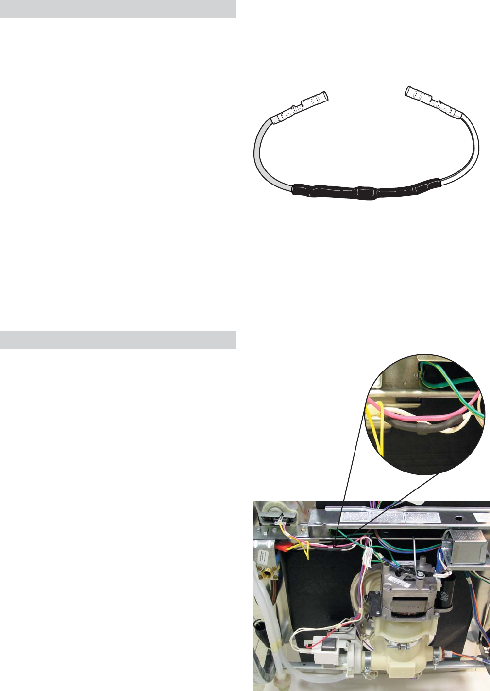
Transorb
The dishwasher contains a transient absorber
(transorb) in the water valve circuit. The transorb
absorbs electrical transients created when the
water valve is turned off. It is wired in the harness
between the line and the neutral side of the water
valve circuit. If the transorb fails, it may create a
short circuit that would cause the circuit breaker
to trip when the water valve is activated.
To check the transorb, disconnect power to the
dishwasher and unplug the connector from the
water valve. Measure the resistance between
the two terminals in the connector. The transorb
is good if the resistance measurement is 100K
ohms or higher.
To replace the transorb, order the kit
WD35X10025. It contains a transorb with two
attached butt connectors and instructions. The kit
allows you to splice a new transorb into the wire
harness.
Transorb Location
A shorted transorb can damage the water valve
circuit in the electronic control. If the transorb
has failed, replace the electronic control along
with the transorb to prevent future related control
problems
– 17 –
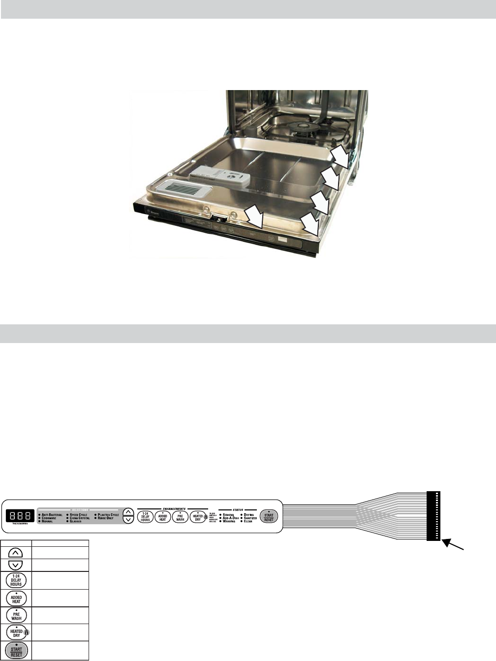
Membrane Keypad
The door panel must be removed to access the membrane keypad (see Door Panel).
• When removing the membrane keypad, peel the keypad from right to left.
• When installing, make sure the membrane button areas and lights align with the keypad.
• On models with an LED display, the display is held in place by 2 Phillips head screws.
Note: When replacing the keypad membrane, always run the Factory Test Mode to calibrate the keypad
membrane to the control board.
1
PADS CONNECTOR PINS
13 & 15
12 & 17
12 & 16
12 & 15
11 & 15
11 & 16
11 & 17
Door Panel
The door panel covers the main control board, detergent cup, vent fan, motor, louver, and door-interlock
switch.
The outer door panel is held in place by 12 screws (5 Phillips head screws per side and two 1/4-in. hex
head screws at the bottom).
Note: Ribbon cable(s) connect the keypad membrane (3-digit display on some models) to the control
circuit board. Due to the ribbon length, care must be taken when removing the door panel to ensure
that the ribbon cable(s) are not damaged.
Note: When troubleshooting, always check resistance between pins 18 and 19:
• 7-keypad membrane should read approximately 22K Ω.
• 6-keypad membrane should read approximately 75K Ω.
When a control pad is pressed, continuity is present on the corresponding pins
(see chart). Example: If the HEATED DRY pad is pressed, you should have
continuity between pins 12 and 17. To locate pin numbers, note location of pin
1 for reference point. (See illustration.)
7-Keypad Membrane Shown
– 18 –
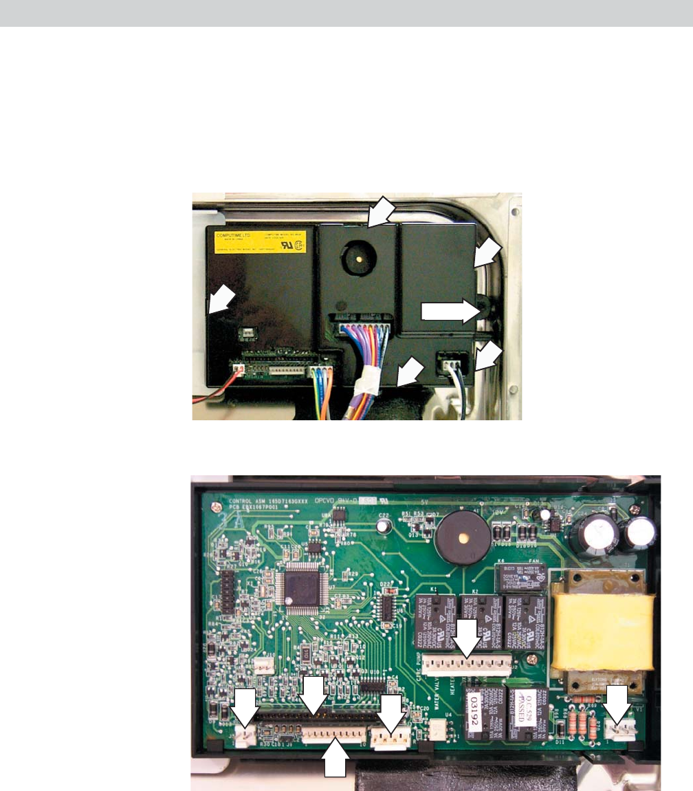
Control Module
The door panel must be removed to access the control module (see Door Panel). The main control is
considered a “smart” control, capable of learning the water temperature and turbidity characteristics of
the home.
It is normal if the cycle times vary over a period of time from the factory default settings due to
temperature and water quality.
The control module is held in place by a single screw that secures the module to the right side of the
inner door panel. (The screw is located on the outside of the inner door panel.)
Screw
J1
J2
J3
J7
J5
J8
J1 - Door Interlock Switch
J2 - Heating Element, Circulation Pump, Drain Pump, Fan, Water Valve, Detergent Module
J3 - Turbidity Sensor
J5 - Vent Louver Motor
J7 - Membrane keypad ribbon cable connector
J8 - LED ribbon cable connector for 3-digit display (some models)
Control Module Board
Note: When replacing
the control module,
always run the Factory
Test Mode to calibrate
the keypad membrane
and turbidity sensor to
the control board.
– 19 –
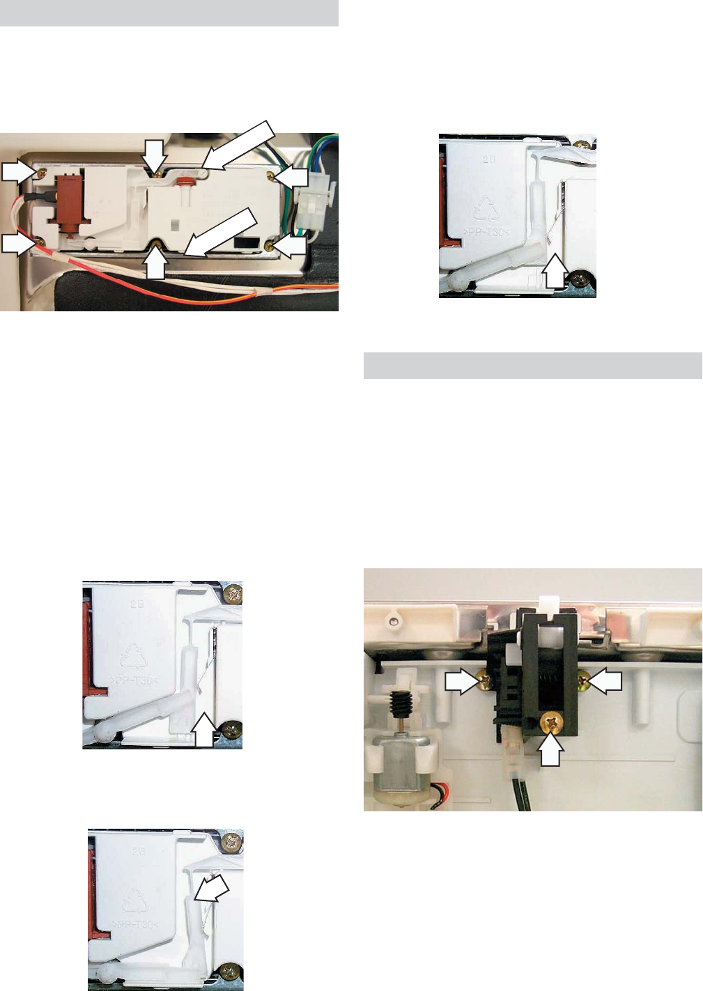
Detergent/Rinse Module
The door panel must be removed to access the
detergent/rinse module (see Door Panel).
The detergent rinse module is held in place by 6
Phillips head screws and 2 brackets.
When deactivated (2), the lever returns down the
left-hand path and comes to rest under the notch
in the center of the connecting rod.
At the second activation (3), the lever lifts the
con nect ing rod by the notch. This action lifts the
rinse dispenser plunger and re leas es the rinse
agent. When deactivated, the lever returns to its
original start ing position.
The detergent/rinse mod ule au to mat i cal ly
dis pens es both the de ter gent and the rinse
agent at the ap pro pri ate times. The module is
activated 2 times during a wash cycle. Detergent
is dispensed at the beginning of the main wash
cycle and rinse agent at the beginning of the
fi nal rinse. The detergent/rinse module can be
activated using Service Mode.
The fi rst time the module is activated:
The lever slides up the right-hand path of the
connecting rod (1). This action releases the
de ter gent cover.
1
2
3
Bracket
Bracket
Door Interlock Switch
The door interlock switch opens the L1 circuit
when the door is open. The switch is replaced as
an assembly.
The door panel must be removed to access the
door latch switch (see Door Panel).
The door latch switch is held in place by 3 Phillips
head screws.
If the door is unlatched while running a wash
cycle, the cycle countdown will pause and the
vent will open. If unlatched for more than 15
seconds during a wash cycle, the control will
beep once every 15 seconds until the door is
relatched.
– 20 –
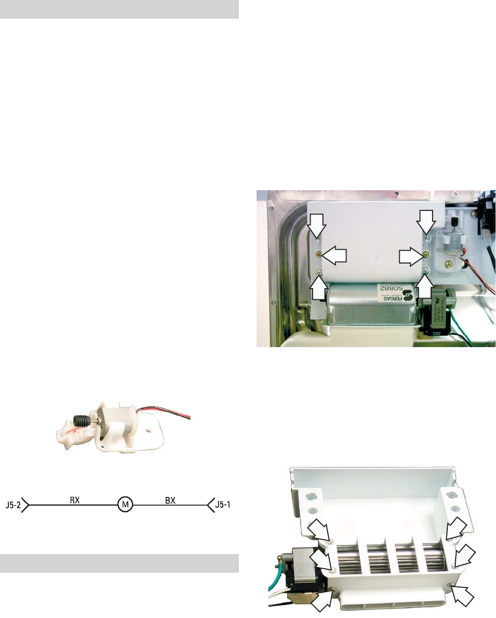
Active Vent
The active vent consists of the fan, motor,
housing, and vent louver motor.
The active vent helps to reduce the noise level
and heat loss when in the closed position. The
control module supplies +/- 12 VDC to the vent
louver motor. The control module reverses
polarity to drive the motor in a clockwise or
counterclockwise (open or closed) direction.
The vent closes 8 seconds after the main pump
is switched on during the fi rst fi ll cycle and opens
during the drying cycle (heated and non-heated).
The vent is open during cooldown periods or
when the unit is not in use.
If the vent is closed and the door is opened during
the wash cycle, the vent will open. When the door
is closed again, the vent will remain open for 8
seconds, then close again to fi nish the cycle.
It is normal for water vapor to come through the
active vent during the dry cycle. The active vent
can be opened and closed using the Service
Mode.
The vent louver is held in place by a single screw.
Remove the motor from the mount by rotating the
motor 90° in the mount and sliding it out between
the tabs.
Note: The gear in the mount is held in place with
the motor.
Vent Motor Strip Circuit
Note: Foam with double-sided tape holds the
conduit in place. The foam tears easily if pulled
during removal of the housing.
Six Phillips head screws hold the fan and motor
to the vent housing.
Note: This also applies to the RINSE ONLY
cycle. Since heated dry is not an option with
RINSE ONLY, the fan will run for approximately 4
hours before turning off.
To access the vent fan and motor, remove the
door panel (see Door Panel).
The vent fan and motor housing are held in place
by:
• 4 long, silver Phillips head screws.
• 2 short, brass Phillips head screws (see
photo).
Fan
During natural dry, the fan runs for approximately
4 hours after the last drain cycle is completed
(clean light on). During heated dry, the fan runs
for approximately 2 hours after the last drain
cycle is completed. If the door is opened, the fan
stops and the control stops counting down. When
the door is relatched, the fan will start again and
the control will continue to count down. Touching
any key will turn off the fan.
– 21 –
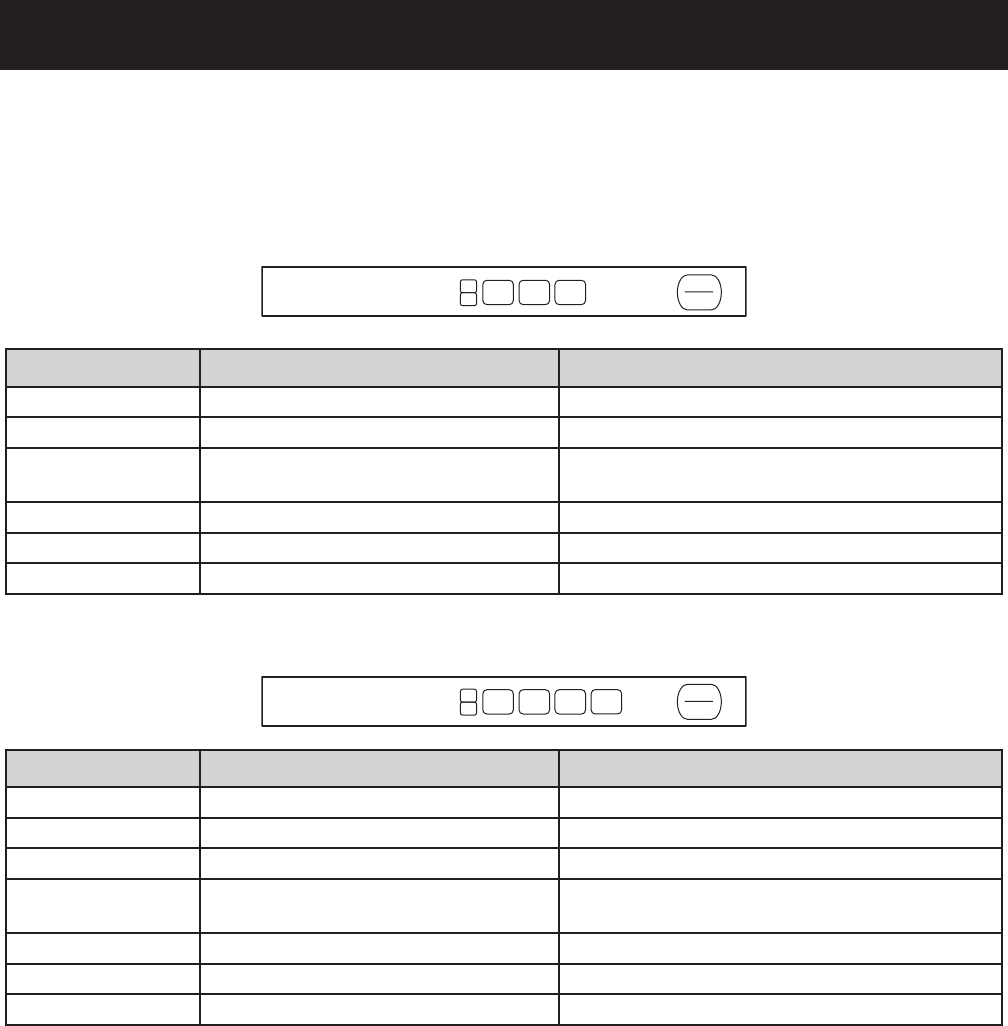
Service Mode
Note: Service mode may be used for 30 minutes maximum. After 30 minutes, the service mode will
automatically turn off.
Note: 3-digit display models only:
• On 3-digit display models, when the service mode activates the auxiliary pump (up arrow pad), the
display shows a digital equivalent of the turbidity value.
• During this test, if the display reads 97, or the value does not change regardless of whether there is
clean or dirty water and the wiring connections are OK, the turbidity sensor should be replaced.
• When the service mode activates the main pump (down arrow pad), the display shows a digital
equivalent of the temperature sensor thermal value.
• During this test, if the display reads 130 regardless of water temperature and the wiring connections
are OK, the turbidity sensor should be replaced.
To enter service mode, press and hold the down arrow and heated dry keypads simultaneously for 3
seconds. All LEDs light for 3 seconds when service mode is entered. To exit service mode, press the
START/RESET at any time.
PAD Description Notes
1L Activates/Deactivates Heater and Fan Test times out after 6 minutes.
2L Activates/Deactivates Water Valve Operates until fl ood switch opens.
3L Activates/Deactivates Detergent Cup Clean LED ON. Can take up to 40 seconds for
detergent cup to open.
4L Activates/Deactivates Auxiliary Pump Cookware LED ON.
5L Activates/Deactivates Main Pump Normal LED ON.
START/RESET Used to exit Service Mode
6 PAD CONTROL
PAD Description Notes
1L Activates/Deactivates Heater and Fan Test times out after 6 minutes.
2L Not Used
3L Activates/Deactivates Water Valve Operates until fl ood switch opens.
4L Activates/Deactivates Detergent Cup Clean LED ON. Can take up to 40 seconds for
detergent cup to open.
5L Activates/Deactivates Auxiliary Pump Cookware LED ON.
6L Activates/Deactivates Main Pump Normal LED ON.
START/RESET Use to exit Service Mode
7 PAD CONTROL
3L
4L
5L
2L 1L
START
RESET
4L
5L
6L
3L 2L
START
RESET
1L

– 22 –
Always run the factory test mode to calibrate when replacing the turbidity sensor, control
module board, and membrane keypanel.
The factory test mode is the most accurate way to test the turbidity sensor circuit which contains
the control module, wiring, and turbidity sensor. Factory test mode will test the thermistor (used for
automatic temperature control) that is contained in the turbidity sensor and will test the transmitter that
is contained in the turbidity sensor.
Entering Factory Test Mode
Note: This mode can only be entered within the fi rst 2 minutes after power-up. After 2 minutes, factory
test mode is unavailable.
Disconnect power from dishwasher. Wait 10 seconds and connect power to dishwasher. Press
the UP and DOWN keypads simultaneously for 3 seconds (This step must be performed within 2
minutes of power-up). The control will step through the test cycle for the preset amount of time. Press
DELAY/START or (DELAY/HOURS on some models) to advance to the next step.
TEST CYCLE
1. All LEDs illuminate for 10 seconds.
2. Vent fan energizes for 5 seconds, then the active vent closes.
3. Detergent module is activated. Water valve energizes for 60 seconds.
4. Main pump is energized. Water valve continues fi lling for an additional 10 seconds.
5. Heater is energized and main pump continues to run for an additional 60 seconds.
6. Dishwasher pauses for 40 seconds. During this time the turbidity sensor, control module board, and
membrane keypad are being calibrated.
a. The control module will beep continuously and the lock icon LED will light if:
1) The temperature sensor check does not fall between the limits (42°F to 199°F).
2) The control receives an analog signal outside the expected range for the turbidity sensor.
3) The EEPROM was not read correctly.
7. Drain pump energizes for 75 seconds.
8. The detergent module is energized for 60 seconds and the water valve is energized for 70 seconds.
9. The heater and main pump are energized for 60 minutes. (Press DELAY/START DELAY/HOURS on
some models) to advance to the next step before control times out.
10. Active vent opens, drain pump is energized for 75 seconds, then active vent closes.
Note: If the calibration test fails, check the following:
• Make certain the dishwasher is not located on a non-insulated outer wall where the temperature at
the turbidity sensor may be below 42°F.
• The turbidity sensor may be dirty. Run a rinse only cycle with one cup vinegar or use citric acid
crystals (WD35X151) to clean the sensor.
Factory Test Mode
– 23 –
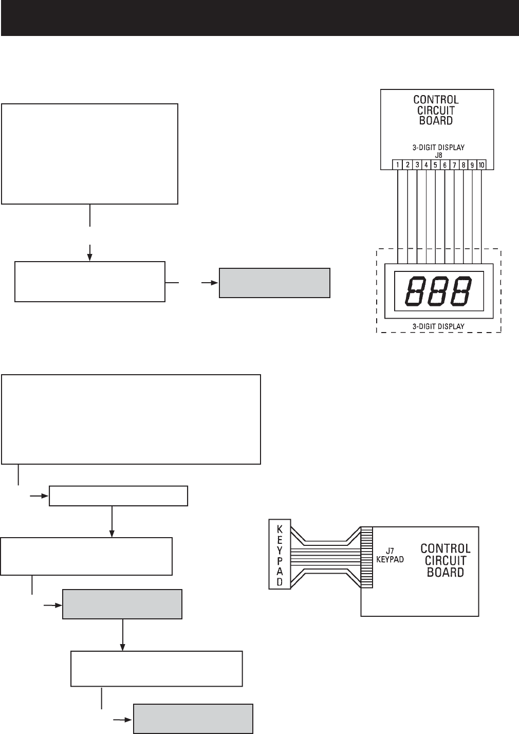
Troubleshooting
Note: Carefully remove the keypad
label. When replacing the keypad label,
make sure the lights and pads align
properly with the membrane.
3-Digit Display Does Not Work
Keypad Does Not Work
Disconnect power to the
dishwasher.
Access the control circuit board.
Remove and reseat the 3-digit
display connector.
Does the display work?
Replace the 3-digit display.
Does the display work?
No
Replace the control
circuit board.
No
Disconnect power to the dishwasher.
Access the control circuit board.
Remove and reseat the keypad connector.
Does the keypad work or activate correct cycles?
Test the keypad. Does the
keypad work?
Replace the control.
Run Factory Calibration.
No
Test the Keypad. Does the
keypad work?
No
No
Replace the keypad.
– 24 –
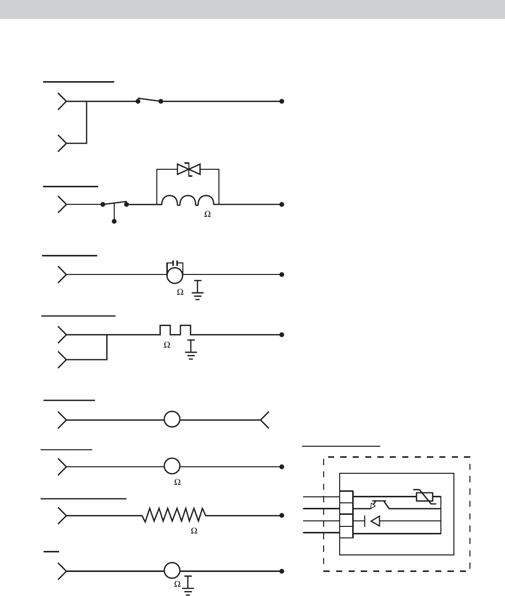
Strip Circuits
1
2
3
4
GY
NX
SX
OX
NTC
TURBIDITY SENSOR
BXBW
BW
NO COM
J2-9
J2-8
DOOR
INTERLOCK
WATER VALVE
DOOR INTERLOCK
J2-2 PX
FLOOD
SWITCH
WATER VALVE
WX
725-1200
CNO
PUMP MOTOR
J2-1
M
CIRCULATION
PUMP
WX
NX
10
HEATING ELEMENT
J2-3
J2-4
VX
VX
WX
HEATING ELEMENT
FAN
J2-7
M
NR WX
DRAIN PUMP
J2-5
M
RX WX
J2-6
DETERGENT MODULE
RY WX
1200-2800
DETERGENT MODULE
DRAIN PUMP
FAN
YX
16
65
VENT MOTOR
J5-2 J5-1
M
RX BX
17
– 25 –
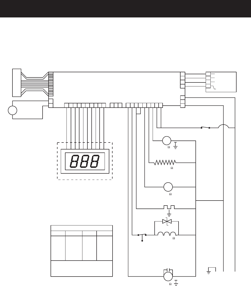
WARNING: Disconnect electrical power before servicing.
Caution: Label all wires prior to disconnection. Wiring errors can cause improper and dangerous
operation. Verify operation after servicing.
Schematic
K
E
Y
P
A
D
CONTROL CIRCUIT BOARD
3-DIGIT DISPLAY
M
ACTIVE
VENT
MOTOR
BX
RX
J7
KEYPAD
12345678910 123 123456789
1
2
J5
ACTIVE
VENT
3-DIGIT DISPLAY
J8
PQA
J10
POWER SWITCHING
J2
1
2
3
1
2
3
4
TURBIDITY/
TEMPERATURE
SENSOR J3
---THIS CIRCUIT NOT IN
ALL MODELS
J1
POWER
SUPPLY
1
2
3
4
NTC
RECEIVER EMITTER
TRANSMITTER
CATHODE
Vcc
GY
NX
SX
OX
M
M
BW
NO COM
BX
DOOR
INTERLOCK
WX
DETERGENT MODULE
FAN
RY
NR
WX
WX
WX
WX
WX
NX WX
CIRCULATION
PUMP
GY
NL1
WX
BX
PX YX
FLOOD
SWITCH
CN
O
WATER VALVE
725-1200
VX
HEATING ELEMENT
RX
DRAIN PUMP
1200-2800
G
10
COLOR CODE
LETTERS COLOR LETTERS COLOR
THE "X" INDICATES ONE SOLID COLOR- NO
TRACER. WIRES WITH TRACER SHOW
BOTH COLORS. EXAMPLE -WR IS WHITE
WITH RED TRACER.
AX
BX
CX
NX
OX
PX
LT. BLUE
BLACK
BROWN
DK. BLUE
ORANGE
PINK
RX
SX
TX
VX
WX
YX
RED
GRAY
TAN
PURPLE
WHITE
YELLOW
16
65
M

– 26 –
Warranty
YOUR MONOGRAM DISHWASHER WARRANTY
Proof of original purchase date is needed to obtain service under warranty.
ONE-YEAR
Any part of the dishwasher which fails due to a defect in materials or workmanship. During
this full one-year warranty, GE will also provide, free of charge, all labor and in-home
service to replace the defective part.
Second Year
Any part of the dishwasher which fails due to a defect in materials or workmanship. During
this second-year limited warranty, you will be responsible for any labor or in-home service
costs.
Five Years
The dishwasher rack and/or the electronic control module, if these should fail due to a
defect in materials or workmanship. During this fi ve-year limited warranty, you will be
responsible for any labor or in-home service costs.
Lifetime
The stainless steel tub or door liner, if it fails to contain water due to a defect in materials
or workmanship. During this full lifetime warranty, GE will also provide, free of charge, all
labor and in-home service to replace the defective part.
This warranty is extended to the original purchaser and any succeeding owner for the
products purchased for ordinary home use in the 48 mainland states, Hawaii, Washington,
D.C. or Canada. In Alaska the warranty is the same except that it is LIMITED because you
must pay to ship the product to the service shop or for the service technician’s travel cost
to your home.
All warranty service will be provided by our Factory Service Centers or by our authorized
Customer Care® servicers during normal working hours.
Should your appliance need service, during warranty period or beyond, in the U.S.A. call
800.444.1845. In Canada: 888.880.3030.
WHAT IS
COVERED
From the Date
of the Original
Purchase
• Service trips to your home to teach
you how to use the product.
.• Improper installation, delivery or
maintenance.
• Replacement of house fuses or
resetting of circuit breakers.
• Failure of the product if it is abused,
misused, or used for other than
the intended purpose or used
commercially.
• Damage to the product caused by
accident, fi re, fl oods or acts of God.
• Incidental or consequential damage
caused by possible defects with this
appliance.
• Cleaning or servicing of the air gap
device in the drain line.
• Damage caused after delivery
including damage from items dropped
on the door.
Some states do not allow the exclusion or limitation of incidental or consequential
damages, so the above limitation or exclusion may not apply to you. This warranty
gives you specifi c legal rights, and you may also have other rights which vary from state
to state. To know what your legal rights are in your state, consult your local or state
consumer affairs offi ce or your state’s Attorney General.
Warrantor: General Electric Company, Louisville, KY 40225.
WHAT IS NOT
COVERED
