Product Recovery Canister Installation And Operation Manual Geotech
User Manual: Pdf Geotech Product Recovery Canister
Open the PDF directly: View PDF ![]() .
.
Page Count: 24

Rev 12/18/12 Part # 26650319
Product Recovery
Canister
Installation and Operation Manual
1
Table of Contents
Section 1: System Description …………………………………………………..…….. 3
Section 2: System Installation and Operation ……………………….………….……. 5
Section 3: System Maintenance …………………………………….…………….…… 6
Section 4: System Troubleshooting ………………………………….………………... 7
Section 5: System Specifications ………………………….……………………….….. 9
Section 6: System Schematic …………………………………………………………. 11
Section 7: Replacement Parts List ………………….……………….………………… 12
Warranty and Repair ……..…………………………………………..………………… 20

2
NOTE
DOCUMENTATION CONVENTIONS
This uses the following conventions to present information:
An exclamation point icon indicates a WARNING of a situation
or condition that could lead to personal injury or death. You
should not proceed until you read and thoroughly understand the
WARNING message.
WARNING
CAUTION
A raised hand icon indicates CAUTION information that relates to
a situation or condition that could lead to equipment malfunction
or damage. You should not proceed until you read and thoroughly
understand the CAUTION message.
A note icon indicates NOTE information. Notes provide additional
or supplementary information about an activity or concept.
3
Section 1: System Description
Function and Theory
The Geotech Product Recovery Canister (PRC) is a passive, skimmer device designed to
recover light floating hydrocarbons (such as gasoline and diesel fuel) from the ground
water in wells that are 2 inches (5cm) and larger.
Featuring a floating oleophilic/hydrophobic intake assembly, the skimmer can
automatically collect and skim floating product down to a sheen. Standard 2” skimmers
provide 12” (30cm) of intake travel and standard 4” skimmers provide upto 16” (40cm) of
intake travel, to accommodate water fluctuations. The unit is suspended in the well at the
desired recovery depth by the 25 feet (7.6m) of supplied stainless steel suspension cable.
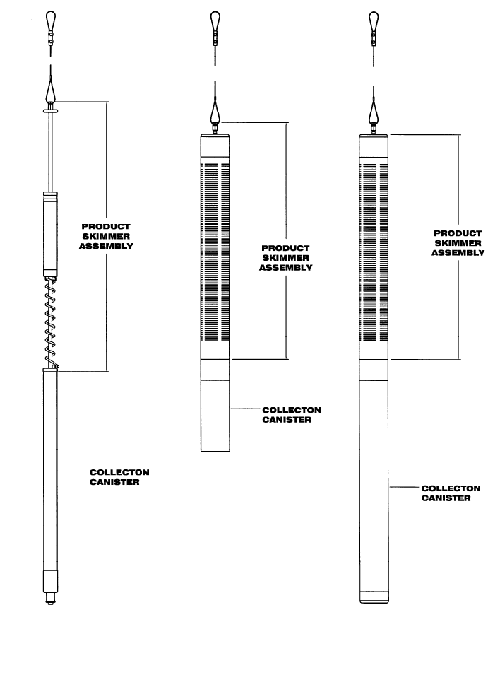
System Components
A PRC consists of two (2) major components; a product skimmer assembly and a
collection canister (as shown in Figures 1-1 through 1-3). On the 4” model, the skimmer
assembly is protected by a slotted screen which pre-filters the incoming product and
protects the intake assembly from damage. The skimmer assembly collects free product
and passes it through a coiled hose to the collection canister. Recovered product is
evacuated by removing the PRC from the well and opening the drain on the bottom of the
device.
Increased capacity collection canisters are available and easily installed by simply
unscrewing the collection canister section and replacing it with a larger collection canister
and weight assembly. When going from smaller to larger collection canisters,
consideration must be made for weight. Going from larger to smaller is not a problem.
4
Figure 1-1 - 2” PRC
Skimmer Assembl
y
Figure 1-2 - 4” PRC
Skimmer Assembl
y
1 Figure 1-3 - 4” PRC
Skimmer Assembl
y
3
5
Section 2: System Installation and Operation
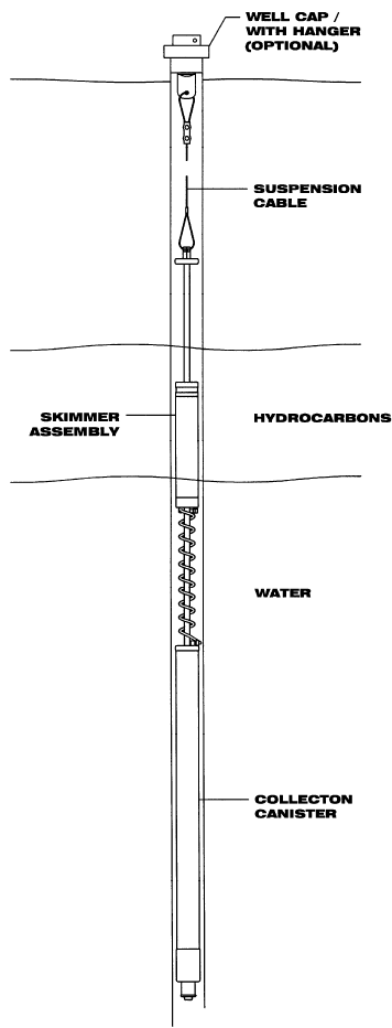
To install the PRC first measure the water and product levels with an Interface Probe
(Geotech can provide you with a variety of Interface Probes for all applications).
Typically, the PRC is set so that the intake assembly is placed at the midpoint of its travel
to allow for water table fluctuation in both directions (see Section 6 for an example of a
PRC in the well). To set the intake assembly at the midpoint of travel, measure from the
top centralizer (2” skimmer), or top cap (4” skimmer) on the PRC and along the
suspension cord, the same distance as the water level reading taken with an Interface
Probe, then subtract 6 inches (15cm). Suspend the PRC from the wellhead to this point.
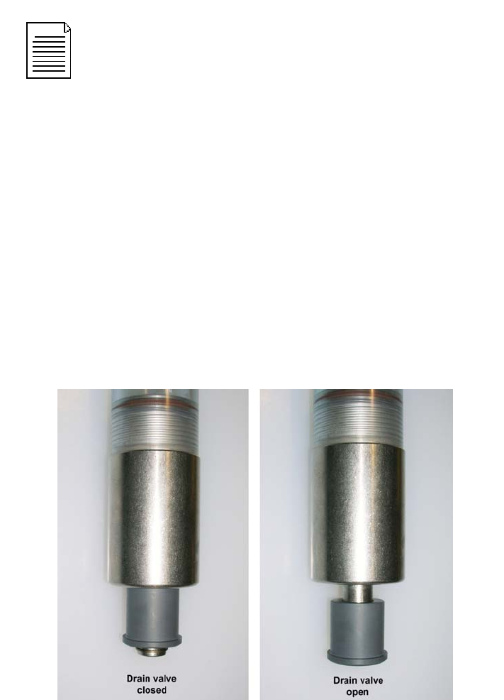
To empty the collection canister, simply pull the PRC up from the well, open the drain
valve (by applying a downward pulling force on the valve sleeve – like a water bottle) and
transfer the recovered product into an approved container.
When re-installing, verify that the intake assembly will be set within its range of travel (as
describe above), and that the drain valve is completely closed to avoid the possibility of
water entering the canister. Figure 2-1 shows an example of the drain valve open and
closed.
Figure 2-1 Drain valve operation
Prior to installation, the oleophilic/hydrophobic screen intake must be
“conditioned”, or primed. To accomplish this, use diesel fuel or similar
hydrocarbon to saturate the screen portion of the intake assembly (as
shown in the figures found in Section 7). The optimum fluid would be
the downwell hydrocarbons to be recovered. Take care to avoid
damaging the intake assembly.
6
Section 3: System Maintenance
With proper maintenance the Geotech PRC will provide years of reliable service. When
emptying the canister, these simple maintenance steps can be taken to assure its
reliability.
1. Inspect the product skimmer assembly for signs of physical damage. Scrapes or
dents in the screen intake may cause the skimmer to take on water. If such
damage is found, a new replacement intake assembly may be necessary.
2. Inspect the tubing coil for physical damage or obstructions, such as kinks.
Replace the tubing coil as necessary.
3. Inspect the collection canister for physical damage such as cracks. Replace as
necessary.
4. To clean the intake assembly screen intake, use a very soft bristle paint brush
and fresh diesel fuel or the type of product being recovered. Typically, this type of
maintenance should only be performed when the screen is obstructed with
emulsified product or other debris. Take care not to dent or scratch the screen
intake.
5. Use diesel fuel or similar hydrocarbon to saturate the screen portion of the
intake. The optimum fluid would be the downwell hydrocarbons to be recovered.
Take care to avoid damaging the screen intake.

7
Section 4: System Troubleshooting
Problem: The PRC recovers only water.
Solutions:
1. The PRC is set too low in the well restricting the travel of the intake assembly.
2. Drain the collection canister completely, allow the screen intake to dry, re-prime
the screen, then reset the PRC so that the water level fluctuation is within the
travel range of the intake assembly.
Problem: The water level has risen past the top of the travel range of the intake
assembly.
Solution:
Drain the collection canister completely, allow the screen intake to dry, re-prime the
screen, then reset the PRC so that the water level fluctuation is within the travel range of
the intake assembly.
Problem: The drain valve is not fully closed.
Solution:
Empty the collection canister (as described in Section 2), and then close the drain valve
by pushing up on the outer sleeve of the drain valve until it stops.
Problem: There is a mechanical malfunction or a leak has developed.
Solution:
Call Geotech Environmental Equipment Inc. at 1-800-833-7958 for assistance.
Problem: The skimmer intake is not recovering product.
Solutions:
1. There is no product to recover.
2. Check, and periodically monitor, the product layer thickness.
If the water level has risen above the travel range of the intake
assembly at any time between site visits, the skimmer
assembly and collection canister will fill up with water and
displace any collected product. It will remain this way until
reset, even if the water level falls back within the travel range of
the intake assembly.
8
Problem: The skimmer is set too high.
Solution:
Recheck the water and product levels and reset the skimmer assembly (use the
installation procedures described in Section 2).
Problem: The canister vent is blocked.
Solution:
Make sure that the holes in the suspension fitting are clear of debris. The PRC will not
operate if these holes are plugged.
Problem: The intake assembly is obstructed or the coiled product hose is kinked.
Solution:
Refer to Section 3, “System Maintenance”.

9
Section 5: System Specifications
Overall Dimensions
Size Volume (L) Dimensions
2"
0.25 49.0"L (149cm) x 1.75" OD (4.4cm)
0.5 59.5"L (151cm) x 1.75" OD (4.4cm)
1 82.5"L (210cm) x 1.75" OD (4.4cm)
2" (With
Screen)
0.25 49.0"L (149cm) x 1.88" OD (4.8cm)
0.5 59.5"L (151cm) x 1.88" OD (4.8cm)
1 82.5"L (210cm) x 1.88" OD (4.8cm)
4"
1 37"L (94cm) x 3.5" OD (9cm)
3 53.0"L (135cm) x 3.5" OD (9cm)
4 60.0"L (152cm) x 3.5" OD (9cm)
Weight
Size Volume (L) Empty Weight Full Weight
2"
0.25 3.1lbs (1.4kg) 3.5lbs (1.6kg)
0.5 3.5lbs (1.6kg) 4.3lbs (2.0kg)
1 5.2lbs (2.4kg) 6.7lbs (3.0kg)
2" (With
Screen)
0.25 4.5lbs (2.0kg) 4.9 lbs (2.2kg)
0.5 4.9lbs (2.2kg) 5.7lbs (2.6kg)
1 6.6lbs (3.0kg) 8.1lbs (3.7kg)
4"
1 8.0lbs (3.7kg) 9.5 lbs (4.3kg)
3 15.0lbs (6.8kg) 19.0lbs (8.6kg)
4 18.0lbs (8.2kg) 25.5lbs (11.6kg)

10
Overall Dimensions
Size Volume (L) Capacity (gallons)
2"
0.25 0.07
0.5 0.13
1 0.26
4"
1 0.26
3 0.8
4 1.06
Minimum Water Required
Size Volume (L) Depth
2"
0.25 29.0" (74cm)
0.5 39.5" (100cm)
1 62.0" (157cm)
4"
1 18.5" (47cm)
3 35.0" (89cm)
4 43.0" (109cm)
11
Section 6: System Schematic
Figure 6-1 – PRC Skimmer deployed in well
12
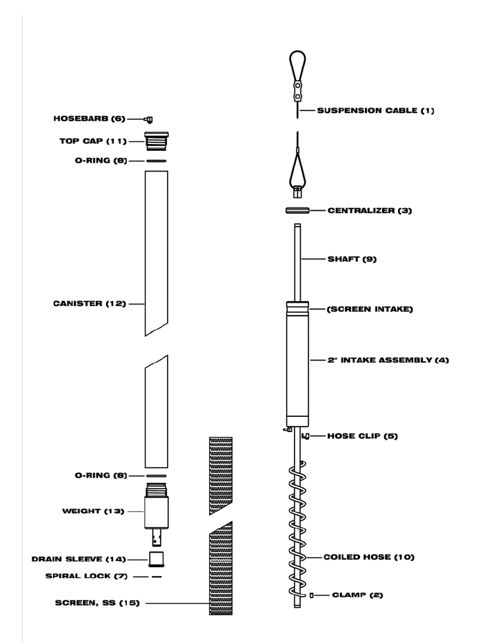
Section 7: Replacement Parts List
Figure 7-1 – Standard 2” PRC Skimmer Assembly

13
Part numbers for the Standard 2” PRC Skimmer Assembly
Item # Parts Description Parts List
1 ASSY,CABLE,SUSPENSION,PRC,25FT 56650305
2 CLAMP,SS,STEPLESS EAR,7MM 16600005
3 CENTRALIZER,PVC,SKIMMER,2" 26650306
CENTRALIZER,PVC,SCREENED PR2 26600186
4 ASSY,BUOY,SKIMMER,2"100MESH 56650309
ASSY,BUOY,SKIMMER,2" 60 MESH 56650312
5 HOSE CLIP,SKIMMER FLOAT 26650028
6 HOSEBARB,BRS,1/8"X10-32,90DEG 17500149
7 LOCK,SS,9/16",SPIRAL 16650304
8 O-RING,VITON,#123 (BROWN) 11200299
9 SHAFT,SS,SKIMMER,33.5",PRC 26600002
10 HOSE,COILED,PR2 26650304
11 CAP,PVC,TOP,PRC2 26650315
12 BODY,PVC,CANISTER,0.125L,PRC 26650321
BODY,PVC,CANISTER,0.25L,PRC 26650307
BODY,PVC,CANISTER,0.5L,PRC 26650311
BODY,PVC,CANISTER,1LITER,PRC 26650313
13 ASSY,WEIGHT,SKIMMER,2",.125L PRC, 56650303
ASSY,WEIGHT,SKIMMER,2",.25/.5L PRC, 56650302
ASSY,WEIGHT,SKIMMER,2",1L PRC 56650301
14 ASSY,SLEEVE,DRAIN,W/ O-RINGS 56650308
15 SCREEN,SS,1.88"ODX32.7" STRAIGHT WELD 26600188
14
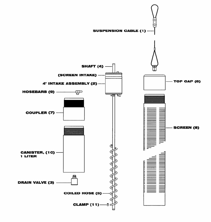
Figure 7-2 – Standard 4” PRC Skimmer Assembly (1 Liter)

15
Part numbers for the Standard 4” PRC Skimmer Assembly (1 Liter)
Item # Parts Description Parts List
1 ASSY,CABLE,SUSPENSION,PRC,25FT 56650305
2 ASSY,BUOY,SKIMMER,4"100 MESH 56650310
3 ASSY,DRAIN VALVE,SKIMMER,4" PR4, 56650307
4 SHAFT,SS,SKIMMER,24.5" 2065 REV A 26650305
5 HOSE,COILED,PR4 16650312
6 CAP,PVC,TOP,PRC4 16650313
7 COUPLER,PVC,PRC4 16650316
8 SCREEN,PVC,PRC4 16650317
9 HOSEBARB,BRS,.170"X1/8MPT,90D 17500148
10 CANISTER,1L,PRC4,W/ BTM PLATE 56650311
11 CLAMP,SS,STEPLESS EAR,7MM 16600005
16
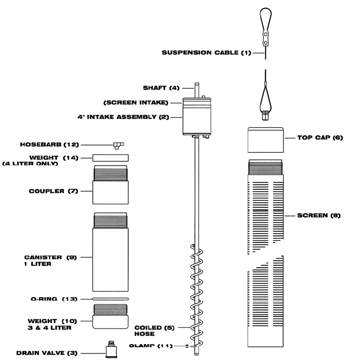
Figure 7-3 – Standard 4” PRC Skimmer Assembly (3 & 4 Liter)

17
Part numbers for the Standard 4” PRC Skimmer Assembly (3 & 4 Liter)
Item # Parts Description Parts List
1 ASSY,CABLE,SUSPENSION,PRC,25FT 56650305
2 ASSY,BUOY,SKIMMER,4"100 MESH 56650310
3 ASSY,DRAIN VALVE,SKIMMER,4" PR4, 56650307
4 SHAFT,SS,SKIMMER,24.5" 2065 REV A 26650305
5 HOSE,COILED,PR4 16650312
6 CAP,PVC,TOP,PRC4 16650313
7 COUPLER,PVC,PRC4 16650316
8 SCREEN,PVC,PRC4 16650317
9 CANISTER,PVC,3L,PRC4 16650318
CANISTER,PVC,4L,PRC4 16650320
10 WEIGHT,SS4,3L&4L,PRC4 16650319
11 CLAMP,SS,STEPLESS EAR,7MM 16600005
12 HOSEBARB,BRS,.170"X1/8MPT,90D 17500148
13 O-RING,VITON,#041 16650321
14 WEIGHT,SS4,4L,PRC4 26650318
18
NOTES
19
NOTES
20
The Warranty
For a period of one (1) year from date of first sale, product is warranted to be free from
defects in materials and workmanship. Geotech agrees to repair or replace, at Geotech’s
option, the portion proving defective, or at our option to refund the purchase price thereof.
Geotech will have no warranty obligation if the product is subjected to abnormal operating
conditions, accident, abuse, misuse, unauthorized modification, alteration, repair, or
replacement of wear parts. User assumes all other risk, if any, including the risk of injury,
loss, or damage, direct or consequential, arising out of the use, misuse, or inability to use
this product. User agrees to use, maintain and install product in accordance with
recommendations and instructions. User is responsible for transportation charges
connected to the repair or replacement of product under this warranty.
Equipment Return Policy
A Return Material Authorization number (RMA #) is required prior to return of any
equipment to our facilities, please call our 800 number for appropriate location. An RMA #
will be issued upon receipt of your request to return equipment, which should include
reasons for the return. Your return shipment to us must have this RMA # clearly marked
on the outside of the package. Proof of date of purchase is required for processing of all
warranty requests.
This policy applies to both equipment sales and repair orders.
FOR A RETURN MATERIAL AUTHORIZATION, PLEASE CALL OUR
SERVICE DEPARTMENT AT 1-800-833-7958.
Model Number: ________________
Serial Number: ________________
Date of Purchase: ________________
Equipment Decontamination
Prior to return, all equipment must be thoroughly cleaned and decontaminated. Please
make note on RMA form, the use of equipment, contaminants equipment was exposed to,
and decontamination solutions/methods used. Geotech reserves the right to refuse any
equipment not properly decontaminated. Geotech may also choose to decontaminate the
equipment for a fee, which will be applied to the repair order invoice.

Geotech Environmental Equipment, Inc.
2650 East 40th Avenue Denver, Colorado 80205
(303) 320-4764 ● (800) 833-7958 ● FAX (303) 322-7242
email: sales@geotechenv.com website: www.geotechenv.com
