Grant UK Aerona3 Installation And Servicing Instructions DOC 0109 Rev 1.1 May 2016
User Manual: Pdf
Open the PDF directly: View PDF ![]() .
.
Page Count: 72
- Contents
- 1 - Introduction
- 2 - Technical Data
- 3 - Installation Information
- 3.1 - Introduction
- 3.2 - Heating System Design Criteria
- 3.3 - Regulations
- 3.4 - Heat Pump Location
- 3.5 - Preparation for Installation
- 3.6 - Installing the Heat Pump
- 3.7 - Weather Compensation
- 3.8 - Buffer Tanks
- 3.9 - Hydraulic Diagrams
- 3.10 - Before you Commission
- 3.11 - Completion
- 3.12 - Installation Checklist
- 4 - Sealed Systems
- 5 - Domestic Hot Water
- 6 - Electrical
- 7 - Remote Controller
- 8 - Operation
- 9 - Commissioning
- 9.1 - System Setup
- 9.2 - Setting the Day and Time
- 9.3 - Access for Parameter Settings
- 9.4 - Accessing the Parameter Setting Menu (User level)
- 9.5 - Accessing the Parameter Setting Menu (Installer level)
- 9.6 - Parameters Input/Output
- 9.7 - Remote Controller Back Light Display Parameters
- 9.8 - Anti-freeze Function Setting
- 9.9 - Pump Operation and Air Bleeding from Heating System
- 10 - Servicing
- 11 - Fault Finding
- 12 - Spare Parts
- 13 - EC Declaration of Conformity
- 14 - Health and Safety Information
- 15 - Disposal and Recycling
- 16 - Guarantee
- Appendix A
- Notes
UK | DOC 0109 | Rev 1.1 | May 2016
Grant UK Aerona³
Air to Water High Efficiency Heat Pump Range
Installation and Servicing Instructions

GRANT ENGINEERING (UK) LIMITED
Hopton House, Hopton Industrial Estate, Devizes, Wiltshire, SN10 2EU
Tel: +44 (0)1380 736920 Fax: +44 (0)1380 736991
Email: info@grantuk.com www.grantuk.com
This manual is accurate at the date of printing but will be superseded and should be disregarded if specifications and/or appearances
are changed in the interests of continued product improvement. However, no responsibility of any kind for any injury, death, loss, damage
or delay however caused resulting from the use of this manual can be accepted by Grant Engineering (UK) Limited, the author or others
involved in its publication.
All good sold are subject to our official Conditions of Sale, a copy of which may be obtained on application.
© Grant Engineering (UK) Limited 2016. No part of this manual may be reproduced by any means without prior written consent.
Special Text Formats
The following special text formats are used in this manual for the
purposes listed below:
Warning of possible human injury as a consequence of not
following the instructions in the warning.
!WARNING
Caution concerning likely damage to equipment or tools as a
consequence of not following the instructions in the caution.
!CAUTION
Used for emphasis or information not directly concerned with
the surrounding text but of importance to the reader.
NOTE
!

Contents
1 Introduction 4
1.1 General 4
1.2 Outputs 4
1.3 Main Components 4
1.4 Planning Permission 4
1.5 DNO Application 4
1.6 Servicing 4
1.6 Important Advice 4
1.7 Product Contents 4
1.8 Installation Accessories 4
1.9 Heat Pump Components 5
2 Technical Data 6
1.1 Heat Pump Technical Data 6
2.2 Main Supply Cable 6
2.3 Heat Pump Dimensions 7
2.4 Remote Controller Dimensions 8
3 Installation Information 9
3.1 Introduction 9
3.2 Heating System Design Criteria 9
3.3 Regulations 10
3.4 Heat Pump Location 10
3.5 Preparation for Installation 10
3.6 Installing the Heat Pump 12
3.7 Weather Compensation 13
3.8 Buffer Tanks 14
3.9 Hydraulic Diagrams 15
3.10 Before you Commission 16
3.11 Completion 17
3.12 Installation Checklist 17
4 Sealed Systems 18
4.1 Sealed System Requirements 18
4.2 Filling the Sealed System 19
4.3 Pressure Relief (Safety) 19
Valve Operation
5 Domestic Hot Water 20
5.1 Temperature Control 20
5.2 Heat Pump Cylinders 20
5.3 Legionella 21
5.4 Automatic DHW Boost Kit 21
6 Electrical 24
6.1 Wiring Centre 24
6.2 Terminal PCB Input/Output 25
6.3 Power Supply 25
6.4 Tightening Torques 27
6.5 Solar Thermal 27
6.6 Connection of Heating System Controls 27
6.7 Connection of Remote Controller 27
6.8 Wiring Diagrams 28
6.9 System Control Wiring Diagrams 30
7 Remote Controller 32
7.1 Remote Controller 32
7.2 Installation Requirements 32
7.3 Installing the Remote Controller 32
7.4 Connecting the Remote Controller 33
to the Heat Pump
7.5 Buttons 34
7.6 Display Panel 35
8 Operation 36
8.1 Heat Pump Operation 36
8.2 Water Pump Management 37
8.3 Frost Protection 40
8.4 ON/OFF DHW Production Remote 42
Contact
8.5 ON/OFF Heating Remote Contact 43
8.6 Night Mode 44
8.7 Low Tariff 45
9 Commissioning 46
9.1 System Setup 46
9.2 Setting the Day and Time 46
9.3 Access for Parameter Settings 47
9.4 Accessing the Parameter Setting Menu 47
(User level)
9.5 Accessing the Parameter Setting Menu 47
(Installer level)
9.6 Parameters Input/Output 48
9.7 Remote Controller Back Light Display 48
Parameters
9.8 Anti-freeze Function Setting 49
9.9 Pump Operation and Air Bleeding 49
from Heating System
10 Servicing 50
10.1 General 50
10.2 Air Inlet and Outlet 50
10.3 Condensate Disposal 50
10.4 Heating System Connections 50
10.5 Heat Pump Controls 50
10.6 Refrigerant 50
10.7 Monitor Display Function 51
11 Fault Finding 52
11.1 Error Code Display 52
11.2 Error History Display 52
11.3 Reset Error Code Display 52
11.4 Error Codes 53
11.5 Table of Controller PCB and Terminal 56
PCB Alarms
11.6 Error Codes and PCB Alarm Figures 57
and Tables
12 Spare Parts 60
12.1 Exploded Diagram - HPID6 60
12.2 Spare Parts List - HPID6 61
12.3 Exploded Diagram - HPID10 62
12.4 Spare Parts List - HPID10 63
12.5 Exploded Diagram - HPID16 64
12.6 Spare Parts List - HPID16 65
13 Declaration of Conformity 66
14 Health and Safety Information 67
14.1 General 67
14.2 Refrigerant 67
15 Disposal and Recycling 67
16 Guarantee 68
Appendix A 70
Contents Page 3

Section 1: IntroductionPage 4
1.1 General
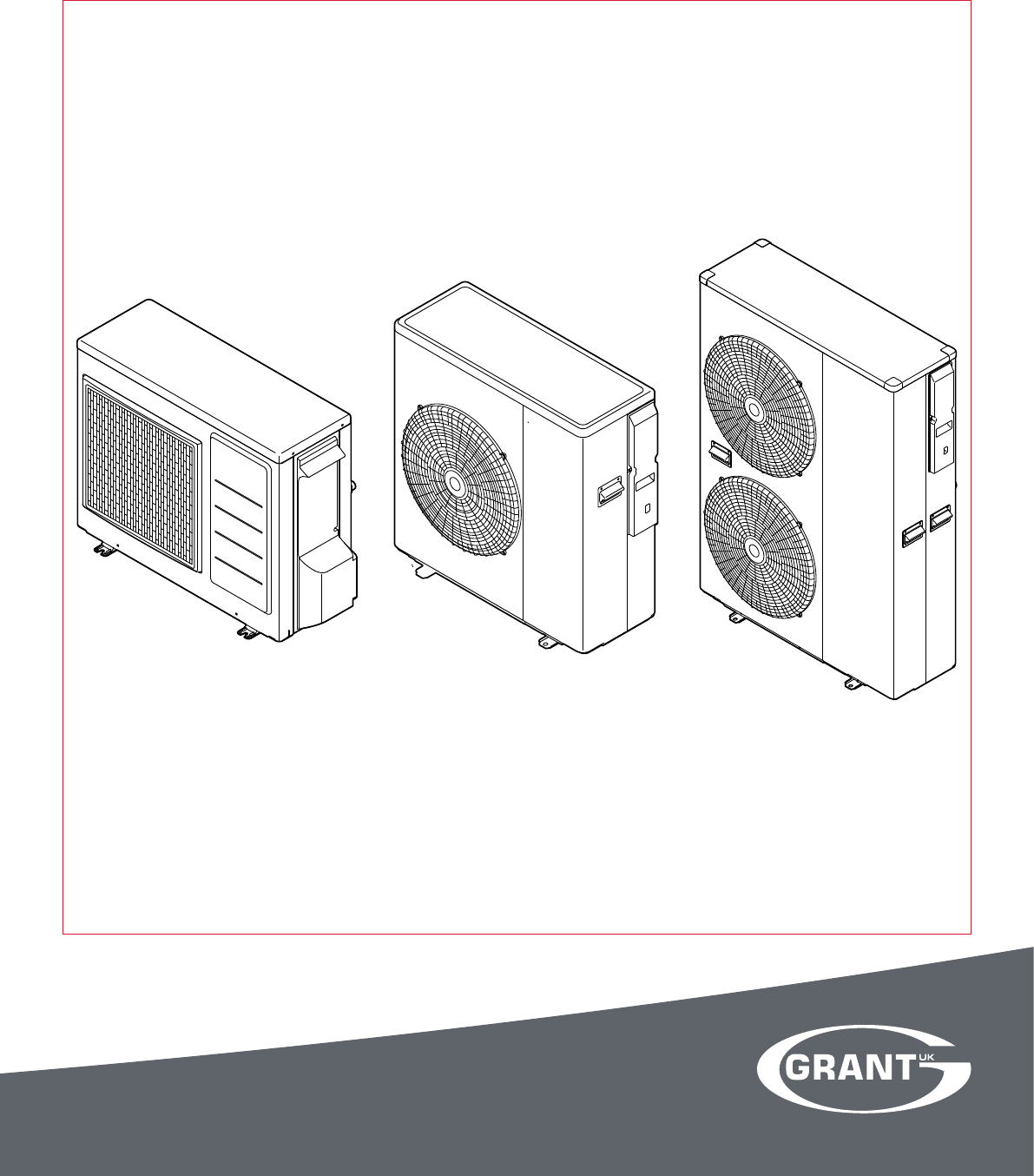
The Grant UK Aerona³ range consists of three compact, lightweight,
MCS approved, monobloc, air-to-water, inverter driven, single-phase
air source heat pumps working with R410A refrigerant.
It is important that these user, installation and servicing instructions
are followed to ensure correct installation and operation. Failure to do
so may result in poor performance.
It is not within the scope of this manual to design the heating system
or provide any advice regarding the layout of the system or any of the
controls required for any individual heating system.
These instructions do not replace the installation or users manuals
for any additional components used in the design of your system e.g.
cylinders, motorised valves, programmers, solar thermal devices,
buffers, etc.
These instructions must be left with the householder for future
reference.
1.2 Outputs
There are three models in the Aerona³ range as follows:
Product code Output*
HPID6 6kW
HPID10 10kW
HPID16 16kW
* 7°C air and 35°C flow temperature
1.3 Main Components
Each model incorporates the following main components:
• DC Inverter
This responds rapidly to changing conditions to provide the
necessary output to meet heating demands by varying the
speed and output of the compressor, fan and circulating pump.
This reduces the on/off times of the compressor, keeping the
water temperature constant during operation reducing the
electricity consumption.
• Compressor
A high-efficiency DC twin-rotary compressor to provide smooth
performance and quiet operation.
• Plate Heat Exchanger (Condenser)
The high-efficiency plate heat exchanger is used to transfer heat
to the heating system primary circuit.
• Fan
A high-efficiency DC fan motor is used for smooth and quiet
operation. A single fan is fitted to the 6kW (5 blade) and 10kW (3
blade) units. Two fans (3 blade) are fitted to the 16kW unit.
• Circulating Pump
High-efficiency DC pump speed controlled from the ASHP
control PCB.
• Anti-freezing heater
Factory fitted electric heater prevents condensate in the base of
the heat pump from freezing.
• Pressure Relief Valve
A 3 bar pressure relief valve is factory fitted.
• Air Purge Valve (Automatic Air Vent)
Factory fitted to assist in the removal of air from the heating
primary circuit of the heat pump.
1.4 Planning Permission
The installation of a Grant UK Aerona³ heat pump on domestic
premises may be considered to be permitted development, not
needing an application for planning permission, provided ALL the
1 Introduction
limits and conditions listed on the Planning Portal website are met.
For further information, visit w ww.planningportal.gov.uk.
1.5 DNO Application
An application must be made to the Distribution Network Operator
(DNO) before connecting the heat pump(s) to the mains electrical
supply. There are six DNOs operating the electrical distribution
network throughout England, Scotland and Wales and the application
must be made to the DNO covering the area concerned.
The necessary information required to make this application (J-forms)
can be downloaded from the Grant UK website (ww w.grantuk.com),
completed and then submitted to the correct DNO for the area in
question.
1.6 Servicing
It is recommended (and a requirement of the product guarantee) that
the heat pump should be regularly serviced, at least once a year and
the details entered in the Service Log by the service engineer.
1.7 Important Advice
1. It is essential that the full layout of the system is understood
before the installation of any component is undertaken. If you
are in any doubt, please stop and seek advice from a qualified
heating engineer or from Grant UK. Please note that Grant UK
will not be able to offer specific advice about your system unless
we designed it. In this case, we will always refer you to seek the
advice of a qualified system designer.
2. The heat pump must be installed and commissioned in
accordance with these user, installation and servicing
instructions. Deviations of any kind will invalidate the guarantee
and may cause an unsafe situation to occur. Please seek advice
from Grant UK if any of these user, installation and servicing
instructions cannot be followed for whatever reason.
3. The heat pump contains high pressures and high temperatures
during normal working conditions. Care must be taken when
accessing the internal workings of the heat pump.
4. The heat pump contains an electrically driven fan which rotates at
high speed. Disconnect the heat pump from the electrical supply
before removing the top cover.
1.8 Product Contents
The Aerona³ comes supplied on a single pallet. The following items
are included:
• 1 x Heat pump
• 1 x Condensate drain elbow
• 4 x Anti-vibration shoes (6kw only)
• 2 x Flexible hoses
• HPID6: 22mm, HPID10: 28mm, HPID16: 35mm
• 2 x Isolating valves
• HPID6: 22mm, HPID10: 28mm, HPID16: 35mm
• 1 x Remote Controller
• 1 x Remote Controller cable (length: 8 metres)
• 1 x Installation, User and Servicing Instructions
1.9 Installation Accessories
The following are available from Grant UK:
Product code Description
HPIDFOOT/KIT Anti-vibration mounts
(2 x 600mm and fixing kit)
HPIDINSU/KIT Through wall insulation kit
(22 - 28mm flexible hoses)
Section 1: Introduction Page 5
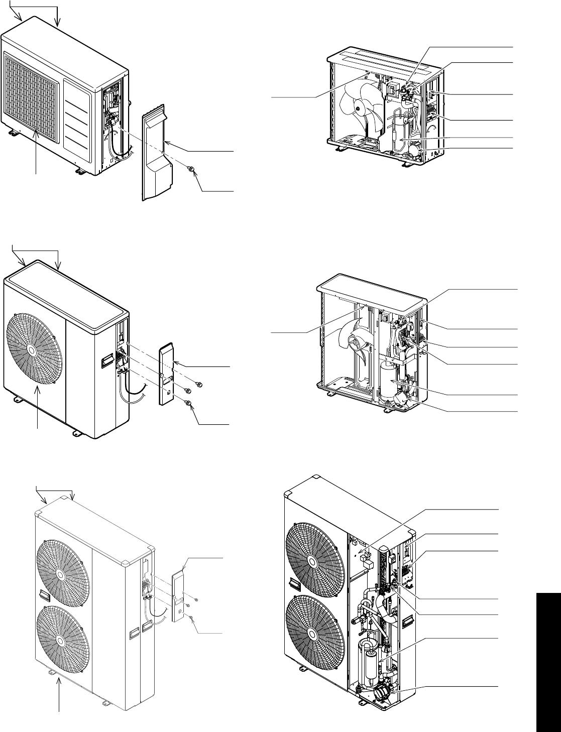
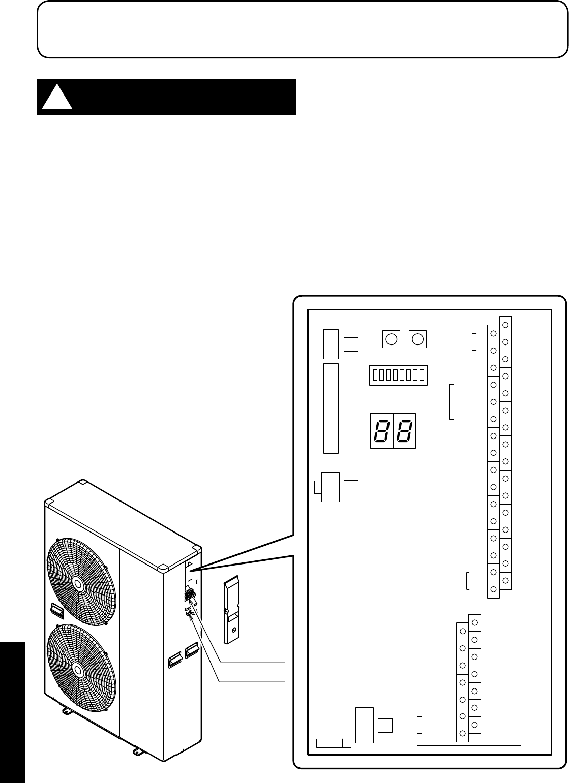
1.9 Heat Pump Components
Air inlet is located in the left and rear of the unit
Air Outlet
Wiring cover
Screw
Air inlet is located in the left and rear of the unit
Air outlet
Wiring cover
Screw
Air inlet is located in the left and rear of the unit
Air outlet
Wiring cover
Screw
Terminal PCB
Auto-air vent
Terminal block
Pump
Compressor
Pressure relief valve
Main PCB
Main PCB
Terminal PCB
Terminal block
Pump
Pressure relief valve
Auto-air vent
Compressor
Terminal PCB
Pressure relief valve
Auto-air vent
Terminal block
Pump
Compressor
Main PCB
Figure 1-1: Main components (external) - 6kW
Figure 1-2: Main components (external) - 10kW
Figure 1-3: Main components (external) - 16kW Figure 1-6: Main components (internal) - 16kW
Figure 1-5: Main components (internal) - 10kW
Figure 1-4: Main components (internal) - 6kW
Section 2: Technical DataPage 6
2.1 Heat Pump Technical Data
Table 2-1: Technical data
Model Unit HPID6 HPID10 HPID16
Heating capacity (BS EN 14511 - air: 7°C / water: 35°C) kW 6.0 10.0 16.0
COP (BS EN 14511 - air: 7°C / water: 35°C) 4.11 4.35 4.10
SCOP (average climate conditions) - 35°C 4.34 4.35 4.19
Heating capacity (BS EN 14511 - air: 7°C / water: 55°C) kW 5.38 9.0 13.3
COP (BS EN 14511 - air: 7°C / water: 55°C) 2.59 2.71 2.67
SCOP - average climate conditions (BS EN 14825 - water: 55°C) 3.15 3.15 3.15
Power supply 230V 1ph 50Hz
Power input (BS EN 14511 - air: 7°C / water: 35°C) kW 1.46 2.30 3.90
Mechanical protection IPX4
Compressor DC twin rotary - inverter driven
Pressure (maximum) MPa 4.1
Refrigerant R410A
Mass of R410A kg 1.05 1.72 2.99
Circulating pump m head 6 10 12
Flow rate (minimum) litres/min 5 10 15
Outdoor temperature °C -20 to 43
Inlet water temperature °C 5 to 55
Water pressure (system) MPa (bar) 0.1 to 0.3 (1 to 3 bar)
Sound power level at 1 metre (external) dB(A) 63 67 63
Sound pressure level at 1 metre (external) dB(A) 40 44 40
Water connections BSPF ¾˝ 1˝ 1¼˝
Weight (empty) kg 53 75 121
Weight (full) kg 54 76.8 123
Water content litres 1.0 1.8 2.0
Heat pump casing volume m³ 0.19 0.27 0.48
ErP rating (low temperature: 35°C flow) - heating
A++
ErP rating (low temperature: 55°C flow) - heating
2.2 Mains Supply Cable
Always assume maximum possible load when considering
cable sizing.
The cable supplying power from the consumer unit to the heat pump
must be connected via an external 2 pole isolator. This allows the
service engineer to isolate the power supply before working on the
heat pump safely.
Refer to Section 6 for connection details.
Table 2-2: Electrical installation requirements
Heat pump
model
Maximum
running current
(A)
MCB
Rating (A) Type
HPID6 11.2 16 C
HPID10 17.5 20 C
HPID16 25.3 32 C
2 Technical Data
Section 2: Technical Data Page 7
2.3 Heat Pump Dimensions
327
57
388 54
R3/4(20A)
30015.3 42
825 73
16 659
580
122.5122.5
43
Circulating water
return port
Circulating water
flow port
86616
850 21
R1(25A)
R1(25A)
25 330 38
480173
155540155
7570
357
Circulating water
return port
Circulating water
flow port
680185
36
356
13 330 13
80 80
241000
1418
205590205
Circulating water
flow port
Circulating water
return port
R1 1/4(32A)
R1 1/4(32A)
Figure 2-5: HPID16 dimensions
Figure 2-4: HPID10 dimensions
Figure 2-3: HPID6 dimensions
Section 2: Technical DataPage 8
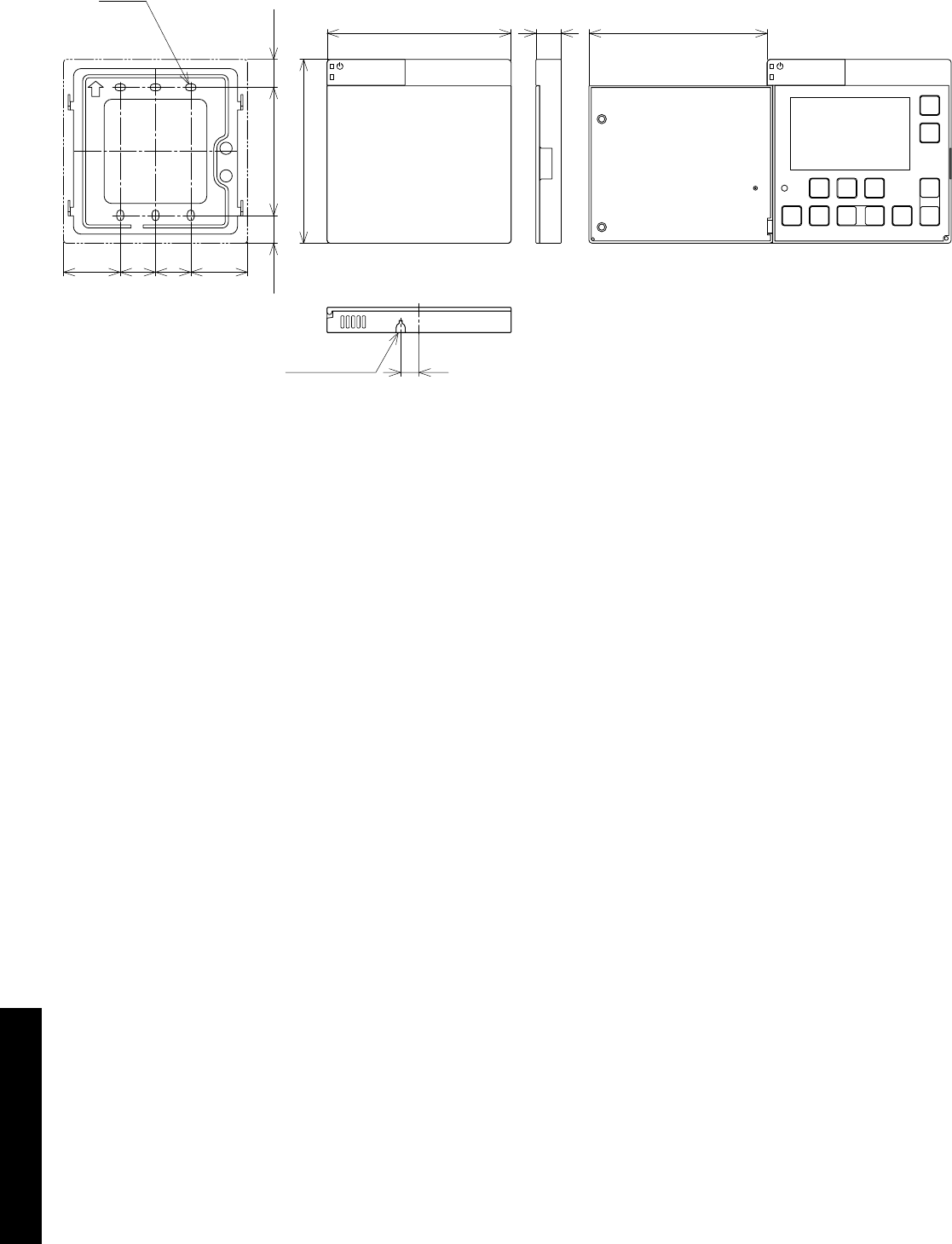
2.4 Remote Controller Dimensions
12
37 37
23 23
18.25
120 16.5
6-4.2×7
120
83.5 18.25
(116)
Knock out hole
Mounting plate Door closed Door open
Figure 2-6: Remote controller dimensions

Section 3: Installation Information Page 9
3.2 Heating System Design Criteria
Before continuing with the installation of the Aerona³ heat pump,
please spend a few minutes confirming the suitability of the heat
pump to your system. Failure to do so may result in poor performance
and wasted time:
• Has a room-by-room heat loss calculation been carried out?
• Is this system designed for mono or bivalent?
• If monovalent, total heating capacity?
• If bivalent, what is the load capacity of the heat pump?
• If bivalent, what is/are additional heat source(s)?
• Type of system design? - S-plan, S-plan plus
• Will a buffer be used?
• If yes, what is the capacity of the buffer?
• Has cavity wall insulation been installed?
• Has loft insulation of 270mm been installed?
• Have all system pipes been lagged correctly?
• Are the existing controls being upgraded?
3.2.1 System Design Criteria
A typical condensing oil or gas fired boiler operates with a flow
of 70°C and a return of 50°C, i.e. with a DT of 20°C. A heat pump
operates with a flow of between 30°C and 55°C with a DT of 8°C.
The design of any system in the UK is typically based on the following
parameters:
1. That the outside design air temperature can fall to -3°C or lower
2. The internal design temperature can be between 18-22°C
depending on the room concerned.
3. The heat pump operates at lower water temperatures than an oil
or gas fired appliance.
Designing a new system for use with a heat pump is
straight forward, assuming the insulation properties of the
dwelling meets or exceeds current Building Regulations and
the lower flow/return temperatures are taken into account in the
selection of the type and size of the heat emitters used.
While underfloor heating is the preferred heat emitter, a combination
of underfloor heating and radiators, or radiators only, works just as
efficiently. It is necessary, however, to calculate the size of radiator
required accurately – if this is not done, the house will fail to reach the
target temperature and will be costly to rectify after the installation is
complete.
When tested to BS EN 14511, the heat output for an heat pump is
declared at the test conditions of 7°C outside air temperature and
35°C or 55°C water flow temperature.
At all other values of outside air temperature and water flow
temperature the actual Heat Pump output will vary, e.g. the heat
output will:
• decrease with lower outside air temperatures and increase
with higher outside air temperatures at any given water flow
temperature, and
• decrease with higher water flow temperatures and increase
with lower water flow temperatures at any given outside air
temperature
A back-up boiler can be added to the rated output of the heat pump.
Provided that the heat pump is sized correctly for the system, this
back-up heater will only compensate for any short fall in meeting
the heat load for the property below the minimum design air
temperatures.
3.2.2 Heat Emitter Sizing
For guidance on sizing heat emitters, e.g. radiators and/or underfloor
heating, refer to MCS Heat Emitter Guide (MCS 021).
3 Installation Information
3.1 Introduction
Grant Aerona³ heat pumps should be stored and transported
in an upright position. If not, then the heat pump MUST be
positioned in an upright position for at least four hours before
being operated.
NOTE
!
For the heat pump to operate satisfactorily, install it as outlined in this
installation manual.
• The Grant UK Aerona³ heat pump should only be installed by a
competent person.
• Before installing the heat pump, please read the following
installation information carefully and install the heat pump as
instructed.
• Be sure to follow the safety notices given.
• After completing the installation, check the product operates
correctly. Then, explain to the user about the operation and
maintenance requirements as shown in this manual.
• Be sure to install the heat pump in a suitable location that can
support the heat pump when filled. Installation in an unsuitable
location may cause injury to persons and damage to the heat
pump.
• Do not install in a position where there is any possibility of
flammable gas leakage such as from LPG cylinder around the
heat pump. Leaked flammable gas around the heat pump may
cause a fire.
• If the leaked refrigerant is exposed to fire, poisonous gas may be
produced.
• Connect the heat pump with the flexible hoses and valves
supplied, as described in this installation manual.
• Do not use an extension cable.
• Do not turn on the power until all installation work is complete.
• Only use correct Grant UK parts and accessories to avoid
accidents such as electric shock, fire and leakage of water.
• Never touch electrical components immediately after the power
supply has been turned off as electrical shock may occur. After
turning off the power, always wait five or more minutes before
touching electrical components.
• Be sure to connect the power supply cable correctly to the
terminal block as overheating can cause a fire.
• Ensure the wiring lid is fitted following installation to avoid electric
shock at the terminal block.
• Always connect the earth wire to the heat pump.
• Install a correctly rated circuit breaker.
• After installation, the heat pump and heating system must be
commissioned. Hand over all documentation to the end-user and
explain the operating functions and maintenance according to
these instructions.

Section 3: Installation InformationPage 10
3.3 Regulations
Installation of a Grant UK Aerona³ heat pump must be in accordance
with the following recommendations:
• National Building Regulations, e.g. Approved Document G
• Local Bylaws (check with the Local Authority for the area)
• Water Supply (Water Fittings) Regulations 1999
• MCS Installer Standards (if applying for the Renewable Heat
Incentive)
• MIS 3005 (Requirements for contractors undertaking the
supply, design, installation, set to work commissioning and
handover of microgeneration heat pump systems)
• MCS 021 (MCS Heat Emitter Guide for Domestic Heat
Pumps)
The installation should also be in accordance with the latest edition of
the following standards and codes of Practice:
• BS 7671:2008 and Amendments
• BS EN 12831:2003
3.4 Heat Pump Location
3.4.1 Selection of position
• Consider a place where the noise and the air discharged will not
affect neighbours.
• Consider a position protected from the wind.
• Consider an area that reflects the minimum spaces
recommended.
• Consider a place that does not obstruct the access to doors or
paths.
• The surfaces of the floor must be solid enough to support the
weight of the heat pump and minimise the transmission of noise
and vibration.
• Take preventive measures so that children cannot reach the unit.
• Install the heat pump in a place where it will not be inclined more
than 5°.
• When installing the heat pump where it may exposed to strong
wind, brace it securely.
Decide the mounting position as follows:
1. Install the heat pump in a location which can withstand the
weight of the heat pump and vibration. Please make sure it is
installed level.
2. Provide the indicated space to ensure good airflow.
3. Do not install the heat pump near a source of heat, steam, or
flammable gas.
4. During heating operation, condensate water flows from the heat
pump. Therefore, install the heat pump in a place where the
condensate water flow will not be obstructed.
5. Do not install the heat pump where strong wind blows directly
onto the heat pump or where it is very dusty.
6. Do not install the heat pump where people pass frequently.
7. Install the heat pump in a place where it will be free from adverse
weather conditions as much as possible.
3.4.2 Noise Level
All heat pumps make a noise. Discuss the potential nuisance factor
with the end-user when considering the final position of the heat
pump. Take opening windows and doors into account. It is not
essential for the heat pump to be positioned next to a wall of the
house. Behind an out-building may be more suitable so discuss the
options with the end-user.
3.4.3 Orientation
The North face of the building will usually have colder ambient air
than any other side. To ensure maximum efficiency from the Grant
UK Aerona³ heat pump, position the heat pump on a warmer side. In
order of preference, site the heat pump on a South face followed by
either South East or South West, then by East or West. Only install on
a North face if there is no other alternative.
3.5 Preparation for Installation
3.5.1 Base
The heat pump should be installed on a flat trowelled finished
concrete base 150mm thick. This base should extend at least 150mm
beyond the heat pump on three sides.
To avoid bridging the DPC, leave a gap of at approximately 150mm
between the concrete base and the wall of the house.
The heat pump must be raised up from the base by approximately
100mm on suitable anti vibration mounts or blocks.
3.5.2 Clearances
The following minimum clearances must be used to enable the
product to be easily commissioned, serviced and maintained and
allow adequate air flow in and out of the heat pump.
Refer to Table 3-1 and Figure 3-2.
Table 3-1: Clearances
Aspect Minimum clearance required (mm)
To p 300
Bottom Approximately 100*
Front 600
Rear 300
Left 100
Right 600
* Height of A/V mounts (product code: HPIDFOOT/KIT)
Section 3: Installation Information Page 11
3.5.3 Condense Disposal
The underside of the heat pump has a condensate outlet (refer to
Figure 3-3) that allows any condensate to drain from the heat pump.
Provision must be made to safely collect and dispose of the
condensate.
For example, use 1½ waste pipe to form a condensate disposal
system into which the condensate flows from the opening in the
bottom of the heat pump casing running to a suitable gulley or
soakaway.
It is essential that the condensate is able to drain away and not
allowed to run onto any adjacent paths or driveways where, in
winter, this will result in icing and a potential hazard for anyone
walking near the heat pump.
The top of the concrete base must be either level with, or
above, the surrounding ground level.
!WARNING
Condensate outlet
Figure 3-3: Condensate outlet
3.5.4 Vibration
If the vibration from the heat pump is likely to cause a nuisance, use
the anti-vibration mounts (product code: HPIDFOOT/KIT)and fix the
heat pump securely to the mounts.
0
0
3
r
e
v
O mm
Over 600 mm
Over 100 mm
Over 300 mm
Over 600 mm
HPID10
0
0
3
r
e
v
O mm
Over 600 mm
Over 100 mm
Over 300 mm
Over 600 mm
HPID16
0
0
3
r
e
v
O mm
Over 600 mm
Over 100 mm
Over 300 mm
Over 600 mm
HPID6
Figure 3-2: Clearances

Section 3: Installation InformationPage 12
3.6 Installing the Heat Pump
3.6.1 Insulation
The complete water circuit, including all pipework, must be insulated
to prevent heat loss, reducing the efficiency of the heat pump and
also to prevent damage due to frozen pipes.
3.6.2 Connecting the Heating System to the Heat Pump
• Water connections must be made in accordance with diagram in
this manual and the labels on the heat pump.
• Be careful not to deform the heat pump pipework by using
excessive force when connecting.
• Pipework should be flushed before connecting the heat pump.
• Hold the pipe end downwards when removing burrs.
• Cover the pipe end when inserting it through a wall so that no
dust and dirt enter.
• The heat pump is only to be used in a sealed heating
system. It must not be used as part of an open-vented
system.
Before continuing the installation of the heat pump, check the
following points:
• The maximum system water pressure is 3 bar.
• Make sure the hose is connected to the pressure relief valve to
avoid any water coming into contact with electrical parts.
• Air vents must be provided at all high points of the system. The
vents should be located at points which are easily accessible
for servicing. An automatic air purge valve is provided inside the
heat pump. Check that the air purge valve can operate.
• Take care that the components installed in the pipework can
withstand the water pressure.
3.6.3 System Connections
The system connections of the heat pump must be carried out using
the flexible hoses, valves and fittings supplied with the heat pump.
The hydraulic circuit must be completed following the
recommendations below:
1. It is important to install the isolation valves between the heat
pump and the building.
2. The system must have drain cocks in the lowest points.
3. Air vents must be included at the highest points of the system.
4. A system pressure gauge must be installed upstream of the heat
pump.
5. All pipework must be adequately insulated and supported.
6. The presence of solid particles in the water can obstruct the
heat exchanger. Therefore, protect the heat exchanger using a
magnetic filter such as a Grant UK MagOne.
7. After system assembly flush and clean the whole system, paying
particular attention to the state of the filter.
8. A new installation must be thoroughly flushed and cleaned before
filling and adding anti-freeze/biocide/inhibitor.
Do not use the heat pump to treat industrial process water,
swimming pool water or domestic drinking water. Install an
intermediate heat exchanger for all of the above cases.
!WARNING
The hydraulic diagrams do not show the isolation valves, any
expansion vessels, pressure relief valves or filling loops.
More information on these components can be found in Section
3.10
NOTE
!
3.6.4 Remote Controller
For details on how to install the remote controller, refer to Section 7.
For setting, refer to Section 9.
Section 3: Installation Information Page 13
3.7 Weather Compensation
3.7.1 Water Temperature Control Point
The water temperature control point is based on a variable set point
calculated automatically using climatic (weather compensation)
curves as described below.
3.7.2 Heating Climatic Curves
The regulation of the temperature of the outlet water from the heat
pump, in normal winter heating operation, is based on the climatic
curves.
The basic logic is to modulate the temperature of the outlet water
depending on the outdoor air temperature.
Te1(0.0°C) Te2(20.0°C) Outdoor air temperature
Outgoing water
set point
Tm1(45.0°C)
Tm2(30.0°C)
Figure 3-4: Climatic curves
Table 3-5: Weather compensation parameters
Level Parameter Function description Display and input value Remarks
Group Code Default Min. Max. Unit
I 21 02 Maximum outgoing water temperature in Heating mode (Tm1) 45.0 23.0 60.0 0.5°C
I 21 03 Minimum outgoing water temperature in Heating mode (Tm2) 30.0 23.0 60.0 0.5°C
I 21 04 Minimum outdoor air temperature corresponding to ma ximum
outgoing water temperature (Te1) -4 -20.0 50.0 0.5°C
I 21 05 Ma ximum outdoor air temperature corresponding to maximum
outgoing water temperature (Te2) 20.0 0.0 40.0 0.5°C
I 21 41 Hysteresis of water set point in heating 8.0 0.5 10.0 0.5°C
For details of how to access the parameter settings, refer to Section 9.3.

Section 3: Installation InformationPage 14
3.8 Buffer Tanks
3.8.1 Buffer Tanks
If there is insufficient volume of water (<100 litres) in the system a
buffer tank may be required to reduce inefficient heat pump cycling.
This will simply be a vessel to increase the volume of the system.
Buffer tanks are available for this purpose. For further information,
please contact Grant UK on +44 (0)1380 736920.
A buffer tank temperature probe is NOT required as this is not
a thermal store.
NOTE
!
Section 3: Installation Information Page 15
3.9 Hydraulic Diagrams
3.9.1 S-plan type with Buffer (optional)
2
1
3
4
5 6
78
9
15
Static head of system
10 11
10 11 12
13
14
Figure 3-6: Monovalent system - with optional buffer and S-Plan type controls
The above system diagram is only a concept drawing, not a detailed engineering drawing, and is not intended to describe
complete systems, nor any particular system.
It is the responsibility of the system designer, not Grant UK, to determine the necessary components for and configuration of the
particular system being designed including any additional equipment and safety devices to ensure compliance with building and
safety code requirements.
Table 3-7: Key
Key Description
1 Expansion vessel
2 Pressure gauge
3 Pressure relief valve
4 Tundish
5 Removable filling loop
6 Double check valve
7 Automatic air vent
8 Thermostatic radiator valve
9 Automatic bypass
10 Flexible hose
11 Isolation valve
12 Buffer (optional)
13 Motorised 2-port valves
14 Additional circulating pump
(refer to Section 8.2.6)
15 Drain point
Section 3: Installation InformationPage 16
3.10 Before you Commission
3.10.1 Flushing and Corrosion Protection
To avoid the danger of dirt and foreign matter entering the heat pump
the complete heating system should be thoroughly flushed out – both
before the heat pump is operated and then again after the system
has been heated and is still hot.
This is especially important where the heat pump is installed as a
replacement for a boiler on an existing system.
In this case the system should be first flushed hot, before the old
boiler is removed and replaced by the heat pump.
For optimum performance after installation, this heat pump and
the central heating system must be flushed in accordance with the
guidelines given in BS 7593:2006 ‘Treatment of water in domestic hot
water central heating systems’.
This must involve the use of a proprietary cleaner, such as Sentinel
X300 or X400, or Fernox Restorer.
After flushing, a suitable thermal fluid should be used (such as
Sentinel R600) specifically designed for use in air source heat pump
installations. This provides long term protection against corrosion
and scale as well as the risk of the freezing in the external section of
the heating system (i.e. the flexible hoses, condenser and circulating
pump within the heat pump casing) in the event of power failure
during winter months.
In order to avoid bacterial growth, due to the lower system operating
temperatures, a suitable Biocide (such as Sentinel R700) should also
be used in conjunction with the thermal fluid.
Both the thermal fluid and biocide should be added to the system
water when finally filling the heating system.
Alternatively, Fernox HP5C can be used (or HP15C for greater frost
protection).
This is a suitable thermal fluid that already contains a suitable
biocide.
Full instructions on the correct use of thermal fluids and biocides are
supplied with the products, but further information can be obtained
from either ww w.sentinel-solutions.net or w ww.fernox.com.
Failure to implement the above guidelines by fully flushing the system
and using a suitable thermal fluid and biocide corrosion inhibitor will
invalidate the heat pump product guarantee.
Grant Engineering (UK) Limited strongly recommends that a
Grant MagOne in-line magnetic filter/s (or equivalent*) is fitted
in the heating system pipework. This should be installed and
regularly serviced in accordance with the filter manufacturer’s
instructions.
* As measured by gauss. The MagOne magnetic filter has a gauss
measurement of 12000.
3.10.2 Antifreeze concentration in the system
Refer to Table 3.11.
Table 3-11: Antifreeze concentration
% Monoethylene glycol inhibitor 10% 20% 30% 40%
Freezing temperature* -4°C -9°C -15°C -23°C
Correction
factor
Capacity 0,996 0,991 0,983 0,974
Power absorbed 0,990 0,978 0,964 1,008
Pressure drop 1,003 1,010 1,020 1,033
* The temperature values are indicative. Always refer to the temperatures given for the specified product used.
For details of how to access the parameter settings, refer to Section 9.3.
3.10.3 Anti-freeze function setting
This function is factory set to ON - DIP SW1 is set to ON.
This function is not required if ethylene glycol is used in the heating
system to prevent freezing.
To disable the anti-freeze function, remove the wiring lid to access the
PCB Terminal and set DIP SW1 to OFF.
Terminal PCB
ON
1
OFF
DIP SW. position
2 3 456 7 8
Figure 3-8: Anti-freeze function setting
Dip switch positions:
Up: ON
Down: OFF
NOTE
!

Section 3: Installation Information Page 17
3.11 Completion
Please ensure that the heat pump commissioning form (supplied
with the heat pump) is completed in full and that it is signed by the
householder/user.
Leave the copy with the user and retain one copy for your own
records, and return the other copy to Grant UK.
Ensure that these Instructions are handed over to the householder.
3.12 Installation Checklist
Location and positioning
• The vibration damping feet/shoes are fitted (if supplied)
• The heat pump is fixed to the surface or mountings that it rests
on
• Maintenance clearances comply with those given in this manual
• The position of the remote controller complies with the guidance
given in this manual
• All safety requirements have been complied with
Water circuit pipework and appliances
• Water connections have been carried out as per the information
in this manual
• All water connections are tight with no leaks
• The magnetic in-line filter is installed on the primary circuit return
as close to the heat pump as possible but still within the building
and in a position that is easy to access for maintenance
• The pressure gauge with a suitable scale is installed on the
sealed system pipework or expansion vessel manifold
• The connection pipes are suitably supported so that these do not
weigh on the appliance
• The expansion vessel installed on the heating circuit is suitably
sized
• The low-loss header or buffer tank is installed if the water content
is insufficient
• The water circuit has been thoroughly flushed
• The air vent valves are installed at the highest points on the
system
• There is no air in the system (vent if necessary)
• The shut off valves are installed on the inlet/outlet of system
circuit
• The drain valves are installed at the lowest points in the system
• The flexible hoses are installed on the inlet/outlet of system circuit
• The system water content complies with the specification in the
manual
• The DHW immersion heater has been installed in DHW tank for
Legionella prevention
• Suitable water flow rate for operation of the entire heat pump is
achieved as specified in the manual
• All pipes are insulated with suitable vapour barrier material to
prevent formation of condensation and heat loss, with control
and shut-off devices protruding from the insulation
Electrical connections
• All electrical connections are secure
• Electrical connections have been carried out correctly
• Voltage is within a tolerance of 10% of the rated voltage for the
heat pump (230V)
• Electrical power supply complies with the data on the rating plate
and as specified in the manual
• The earth wires are connected securely
Section 4: Sealed SystemPage 18
4.1 Sealed System Requirements
2
1
3
4
5 6
78
9
15
Static head of system
10 11
10 11 12
13
14
Figure 4-1: Sealed System heating components
4 Sealed Systems
Table 4-2: Sealed System heating components key
Key Description
1 Expansion vessel
2 Pressure gauge
3 Pressure relief valve
4 Tundish
5 Removable filling loop
6 Double check valve
7 Automatic air vent
8 Thermostatic radiator valve
9 Automatic bypass
10 Flexible hose
11 Isolation valve
12 Buffer (optional)
13 Motorised 2-port valves
14 Additional circulating pump
(refer to Section 8.2.6)
15 Drain point
All Grant Aerona³ heat pumps must be used with sealed systems
complying with the requirements of BS EN 12828:2003, BS EN
12831:2003 ad BS EN 14336:2004.
The system must be provided with the following items:
• Diaphragm expansion vessel complying with BS EN 13831:2007
• Pressure gauge
• Pressure relief (safety) valve
• Approved method for filling the system
Expansion vessel
The expansion vessel can be fitted in either the return or flow
pipework in any of the recommended positions as shown in Figure
4-1. To reduce the operating temperature of the expansion vessel,
position it below the pipe to which it is connected.
The expansion vessel may be positioned away from the system,
providing the connecting pipe is not less than 13 mm diameter. If the
expansion vessel is connected via a flexible hose, care must be taken
to ensure that the hose is not twisted.
Ensure that the expansion vessel used is of sufficient size for
the system volume.
Refer to BS 7074:1:1989 or The Domestic Heating Design
Guide for sizing the required vessel.
NOTE
!
Section 4: Sealed System Page 19
Pressure Gauge
The pressure gauge must have an operating range of 0 to 4 bar.
It must be located in an accessible place next to the filling loop for the
system.
Safety Valve
The safety valve (provided with the heat pump) is set to operate at 3
bar. It should be fitted in the flow pipework near to the heat pump.
The pipework between the safety valve and heat pump must be
unrestricted, i.e. no valves. The safety valve should be connected
to a discharge pipe which will allow the discharge to be seen, but
cannot cause injury to persons or damage to property.
Filling Loop
Provision should be made to replace water lost from the system. This
can be done manually (where allowed by the local water undertaking)
using an approved filling loop arrangement incorporating a double
check valve assembly.
The filling loop must be isolated and disconnected after filling the
system.
Heating System
The maximum ‘setpoint’ temperature for the central heating water is
55°C.
An automatic air vent should be fitted to the highest point of the
system.
loosen
tighten
Auto air vent
Plug
Figure 4-3: Auto Air Vent
If thermostatic radiator valves are fitted to all radiators, a system
by-pass must be fitted. The by-pass must be an automatic type.
All fittings used in the system must be able to withstand pressures
up to 3 bar. Radiator valves must comply with the requirements of BS
2767:1991.
One or more drain taps (to BS 2879) must be used to allow the
system to be completely drained.
4.2 Filling the Sealed System
Filling of the system must be carried out in a manner approved by the
local Water Undertaking.
Only ever fill or add water to the system when it is cold and the
heat pump is off. Do not overfill.
!WARNING
The procedure for filling the sealed system is as follows:
1. Check the air charge pressure in the expansion vessel BEFORE
filling the system.
The expansion vessel charge pressure should always be
approximately 0.2 bar lower than the maximum static head of the
system, at the level of the vessel (1 bar = 10.2 metres of water).
Refer to Figure 4-1.
The charge pressure must not be less than the actual
static head at the point of connection.
2. Check that the small cap (or screw) on all automatic air vents
is open at least one turn. The cap (or screw) remains in this
position until filling is completed and then it is closed.
3. Remove the front casing and loosen the plug on the automatic
air vent located inside the heat pump. Refer to Figure 4-3.
4. Ensure that the flexible filling loop is connected and that the
double check shut off valve connecting it to the water supply is
closed. A valve is open when the operating lever is in line with
the valve, and closed when it is at right angles to it.
5. Open the fill point valve.
6. Gradually open the double check valve from the water supply
until water is heard to flow.
7. When the needle of the pressure gauge is between 0.5 and 1.0
bar, close the valve.
8. Vent each radiator in turn, starting with the lowest one in the
system, to remove air.
9. Continue to fill the system until the pressure gauge indicates
between 0.5 and 1.0 bar. Close the fill point valve. The system fill
pressure (cold) should be 0.2 - 0.3 bar greater than the vessel
charge pressure – giving typical system fill pressures of approx
0.5 bar for a bungalow and 1.0 bar for a two storey house.
Refer to the Domestic Heating Design Guide for further
information if required.
10. Repeat steps 8 and 9 as required until system is full of water at
the correct pressure and vented.
11. Water may be released from the system by manually operating
the safety valve until the system design pressure is obtained.
12. Close the fill point and double check valves either side of the
filling loop and disconnect the loop.
13. Check the system for water soundness, rectifying where
necessary.
The air charge pressure may be checked using a tyre
pressure gauge on the expansion vessel Schraeder valve.
The vessel may be re-pressurised, when necessary, using
a suitable pump. When checking the air pressure, the water
in the heating system must be cold and the system pressure
reduced to zero.
NOTE
!
4.3 Pressure Relief (Safety) Valve Operation
Check the operation of the pressure relief (safety) valve as follows:
1. Turning the head of the valve anticlockwise until it clicks. The
click is the safety valve head lifting off its seat allowing water to
escape from the system.
2. Check that the water is escaping from the system.
3. Top-up the system pressure, as necessary.
The expansion vessel air pressure, system pressure and
operation of the pressure relief valve must be checked on
each service. Refer to Section 10.
NOTE
!

Section 5: Domestic Hot WaterPage 20
5.1 Temperature Control
If a DHW demand is made, the heat pump will continue to provide
space heating for a minimum period of 15 minutes (parameter 3122
- refer to Table 5-1). If space heating is already being demanded and
has been on for this minimum period, then the heat pump will change
over to prioritise DHW.
In either case, once DHW is being provided, the flow temperature
will target 60°C, irrespective of the space heating target temperature.
Also note that there is no weather compensation control when in DHW
mode.
The time limit for DHW can be set using parameter 3121. The default
setting is 60 minutes but you may want to increase or decrease this
time period. After this time period has been reached, the heat pump
will default back to the original demand that was in place prior to the
DHW demand or to a stand by state if the change is demand state
occurred during the DHW demand.
If the unit times out on parameter 3121, remember the motorised valve
of the DHW circuit will remain open as it is controlled by the cylinder
thermostat and not the heat pump and will not heat up to the correct
temperature when using the space heating flow temperature. It is
also possible that the cylinder could be robbed of heat to the space
heating circuit if the stored water is hotter than the flow temperature to
the space heating circuit.
If the motorised valve for space heating is open during DHW demand,
the 60°C flow temperature will also enter the space heating circuit,
increasing the recovery time of the cylinder.
To minimise this high temperature period and higher than normal
running costs, ensure that space heating and DHW demand times to
not occur simultaneously.
5 Domestic Hot Water
Table 5-1: Parameters
Level Parameter Function description Display and input value Remarks
Group Code Default Min. Max. Unit
I 31 21 Ma ximum time for DHW request 60 0 900 1 min
I 31 22 Minimum time for space heating 15 0 900 1 min
For details of how to access the parameter settings, refer to Section 9.3.
5.2 Heat Pump Cylinders
5.2.1 General
As the water temperature from the heat pump is lower than from a
traditional system using a boiler, a much larger coil is required inside
the cylinder to transfer the heat efficiently.
Grant UK has developed a 200 litre high-efficiency cylinder (Band A)
for use with a combination heat pump. Other Band B and C cylinders
are available but consideration should be given to system efficiency.
Refer to Appendix A (page 70) for more information.
In order to ensure that a minimum of at least 8K temperature
difference is maintained between cylinder flow and return, the correct
Grant UK heat pump cylinder must be selected to match the heat
pump output.
Failure to use the correct cylinder can result in a reduced heat transfer
in the cylinder and a lower temperature differential.
5.2.2 ErP (Energy Related Product Directive)
If a heat pump and cylinder are used as a ‘combination’, a product
fiche and energy label must be provided to the end user.
Please refer to Appendix A (page 70) for details of the correct product
fiche and label.

Section 5: Domestic Hot Water Page 21
5.3 Legionella
It is possible to use the heat pump to raise the HW cylinder to around
50 to 55°C.
For protection against Legionella the temperature can be periodically
raised to 60°C using the Grant Automatic DHW Boost Kit 2, available
from Grant UK (product code: HPDHWBK2).
This boost kit also allows the cylinder immersion element to be used
to raise the temperature to 60°C for one hour either daily or weekly to
sterilise the cylinder against Legionella.
For this system to operate, the existing immersion switch must
be left set permanently to ON.
To totally prevent operation of the immersion element, the
existing immersion switch must be set to OFF.
NOTE
!
5.3.1 Legionella Sanitisation Regime
Care must be given to vulnerable people who may be exposed to
potentially life-threatening legionella. This group of people include
the elderly, pregnant women, young children and those with breathing
difficulties.
Care must also be given to households who do not use a lot of water
on a daily basis. While this chart is not exhaustive, it is important that
you discuss any potential issues with the occupants before deciding
on the appropriate regime. It is important that this decision is based
on the welfare of the occupants and not on energy saving measures.
Table 5-2: Legionella group sanitisation regime
Uses less than 50
litres of hot water
per day
Uses more than 50
litres of hot water
per day
Vulnerable Group
Store at 50°C and raise
hot water cylinder to
60°C for 1 hour every
day
Store at 50°C and raise
hot water cylinder to
60°C for 1 hour every
3 days
Non-Vulnerable Group
Store at 50°C and raise
hot water cylinder to
60°C for 1 hour every
week
Store at 50°C and raise
hot water cylinder to
60°C for 1 hour every
2 weeks
If the hot water stored in the cylinder has not been used for a
prolonged period of time (e.g. a few days) and has not been
stored at 60°C, then it is important that the temperature is
raised to at least 60°C for a period of one hour before using the
hot water.
!WARNING
5.4 Automatic DHW Boost Kit
This system uses both the existing cylinder immersion heater and
cylinder thermostat. This is switched via a contactor operated by a
small timeswitch, both enclosed in a separate unit to be mounted next
to the cylinder. Thus the immersion element can be programmed to
operate for the required period on either a daily or weekly basis.
Once set, this system is fully automatic but can be overridden by the
user if required. Also, the user can still switch the immersion element
off, via the immersion heater switch, irrespective of the programmer or
cylinder thermostat setting or whether the heat pump is operating.
5.4.1 Installation
The Automatic DHW Boost Kit 2 comes pre-wired within its enclosure,
ready for installation. The connections to the Immersion heater switch,
Immersion heater and cylinder thermostat must be made after it is
installed on site.
When installed, this kit interrupts the electrical supply between the
existing immersion heater switch and immersion heater. Refer to
Figure 5-3 for electrical connection details.
In order to connect and use this kit the existing cylinder thermostat
must have two output terminals; one ‘make on rise’ (normally open)
contact and the other ‘break on rise’(normally closed) contact. If not,
then the cylinder thermostat MUST be replaced with one that does
have two output terminals.
The use of any other type of cylinder thermostat, or any modification
to an existing thermostat, will invalidate the product guarantee and
may result in a potentially dangerous installation.
Important
Do not alter the pre-wired connections within the enclosure
and only make the external connections as shown in the wiring
diagrams. See Figure 5-4.
Where a 3-phase supply is present, ensure that BOTH the
immersion switch and heating system controls are taken from
the same phase. If in doubt, contact a qualified electrician.
!WARNING

Section 5: Domestic Hot WaterPage 22
5.4.2 Setting
To set the timeswitch use the following procedure:
To set the time and day:
1. Press and hold down the ‘clock’ button throughout the ‘time and
day’ setting process.
2. Press ‘h+’ button repeatedly to set hour (24 hour clock).
3. Press ‘m+’ button repeatedly to set minutes.
Note. If you hold down either the ‘h+’ or ‘m+’ buttons for longer than
a second the figures in the display will scroll continuously.
4. Press the ‘day’ button repeatedly to scroll through to required day
of week.
5. Release the ‘clock’ button. The clock is now running as indicated
by the flashing colon.
To set switching times:
You can set up to six ON and OFF commands per day, if required, as
follows:
1. Press the ‘timer’ button. The actual time will disappear from the
display. The first ‘ON’ indication will be displayed.
2. Press ‘h+’ button repeatedly to set hour (24 hour clock).
3. Press ‘m+’ button repeatedly to set minutes.
4. Press the ‘day’ button repeatedly to scroll through day options –
each single day, all weekdays, weekend and entire week.
5. Press the ‘timer’ button again. The first ‘OFF’ indication will be
displayed.
6. Repeat steps 2 to 4 (above) to set first OFF time – hours minutes
and day.
IMPORTANT. Ensure that day (or days) for the OFF setting match
those for the ON setting.
7. Press the ‘timer’ button again. The second ‘ON’ indication will be
displayed.
8. Repeat the above procedure to set second ON and OFF times,
if required.
9. After setting all required ON and OFF times – press the ‘clock’
button to return to current time display.
To check ON/OFF settings
Repeatedly press the ‘timer’ button to scroll through all ON and OFF
settings.
To change an ON or OFF setting
When a setting is showing on the display – press the ‘h+’ ‘m+’ or
‘day’ buttons to alter the setting as required.
To delete an ON/OFF setting period
1. Press the ‘timer’ button until the ‘ON’ setting for the period to be
deleted is displayed.
2. Press the ‘h+’ button repeatedly until ‘- -‘appears (after 23
hours).
3. Press the ‘m+’ button repeatedly until ‘- -‘appears (after 59
minutes).
4. Press the ‘timer’ button and the ‘OFF’ setting for the period to be
deleted is displayed.
5. Repeat steps 2 and 3 (above) to delete the ‘OFF’ setting.
6. Press the ‘timer’ button to save the amended command.
7. The deleted ON/OFF period is now available for re-programming
if required.
8. Press the ‘clock’ button to return to the current time display.
To override the timeswitch
If timeswitch is ON - press the ‘override’ button to set timeswitch to
OFF.
If timeswitch is OFF – press the ‘override’ button to set timeswitch to
ON.
Operation
With the Automatic DHW Boost Kit 2 fitted, the HW cylinder thermostat
should be set to between 50 and 55°C for optimum operation. When
the heat pump raises the cylinder to this temperature the cylinder
thermostat will be ‘satisfied’ and switch to the ‘make on rise’ or
‘normally open’ connection.
The HW zone valve, being no longer fed from the cylinder thermostat,
will close.
The resulting switched live from the normally open contact of the
cylinder thermostat supplies power to terminal 3 on the Boost Kit
timeswitch. See Figure 5-3.
When the timeswitch contact closes, at the pre-set time, the output
from terminal 4 of the timeswitch energises the contactor coil, closing
the contactor contacts and connecting the output from the Immersion
heater switch to the immersion heater.
If, whilst the immersion heater is in operation, hot water is drawn
off and the temperature in the cylinder falls to below the cylinder
thermostat setting, the cylinder thermostat will operate and interrupt
the power supply to the Boost kit and the immersion heater will stop
operating.
In this case the heat pump will receive a HW demand to operate, to
heat the HW cylinder.
If the amount of hot water drawn off is small, the temperature drop
in the cylinder may be minimal and the cylinder thermostat may not
detect it.
In this case the cylinder thermostat will continue to supply power to
the Boost kit. The Immersion heater will continue to operate and no
HW demand will be sent to the heat pump.
IMPORTANT
There must be a demand from the HW channel of the heating/hot
water programmer for the Automatic DHW Boost Kit 2 to operate
when required. When setting the ON periods on the Auto Boost
Kit timeswitch, ensure that they are within a HW ON period on the
programmer.
Two separate power supplies are connected within the HW
boost kit enclosure – one from the immersion heater switch
and the other from the heating controls circuit. Ensure that
BOTH supplies are isolated before commencing any work on
the boost kit relay or switch.
A warning label informing the user of this has been fixed on the
enclosure.
THIS LABEL MUST NOT BE REMOVED FROM THE
ENCLOSURE.
!WARNING
Section 5: Domestic Hot Water Page 23
Figure 5-4: Boost kit wiring diagram
1
A1 Cylinder
Stat
1 2
C
2
23
4 3 4
1
A2
Immersion
Heater Switch
Immersion
Heater
HW Controls
To HW Valve
E
N
L
E
N
L
Red
Earth connections have been excluded for
clarity. Ensure all earth connections are made
prior to energising.
The HW boost pack contains a power relay and
an additional 2-pole isolator and programmable
timer.
NOTE
!
Figure 5-3: Boost kit timeswitch
Day h+
Timer M+
R
MO
TU
WE
TH
FR
SA
SU
TIMER
OFF ON
LCD display
Day button
Timer button
Clock button
Hours adjust button
Minutes adjust button
Override button
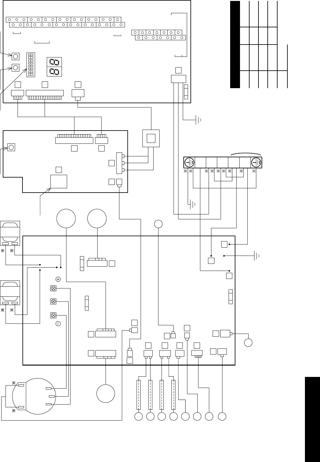
Section 6: ElectricalPage 24
6 Electrical
6.1 Wiring Centre
Electrical shock may cause serious personal injury or death.
All electrical work must be undertaken by a competent person.
Failure to observe this legislation could result in unsafe
installation and will invalidate all guarantees.
All electrical connections made on-site are solely the
responsibility of the installer.
!WARNING
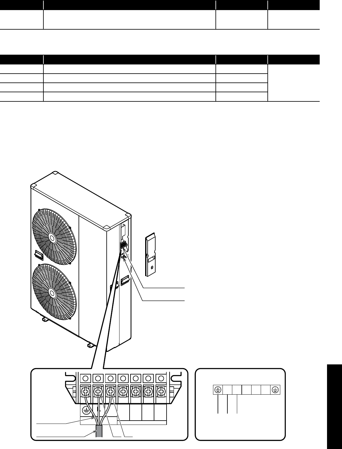
All wiring connections are made to the Terminal PCB (refer to Figure
6-1) and terminal block (refer to Figure 6-3) inside the heat pump.
To access these connections, remove the wiring cover at the right
hand end of the heat pump.
Terminal block
Cable clamp
ON
Reset
SW. Pump
SW.
OFF
Terminal
PCB
3
4
2
1
Remote
Controller
1
2
3
4
5
6
7
17
18
19
20
21
22
23
Humidity
Sensor
COM
DHW Remote
Contact
ON/OFF
or
EHS Alarm
GND
24VAC
COM
Control
DHW
T.probe
OUTDOOR
T.probe
BUFFER
T.probe
Mix water
T.probe
3-way
mixing
valve
RS485
+
-
Dehumidifier
Alarm
Pump1
Pump2
Neutral
N.C.
Neutral
EHS
Heating
Cooling
mode
output
Phase
Signal
3-way
valve
8
9
10
11
12
13
14
Dual Set
Point
Control
Heating
Cooling
mode
Flow
switch
Night
mode
Low
tariff
RS485
GND
45
46
47
48
49
50
31
32
24
25
26
27
28
29
30
15
16
N
41
42
43
44
51
52
Electric
heater
Figure 6-1: Terminal PCB
Section 6: Electrical Page 25
6.2 Terminal PCB Input/Output
Serial connections
Terminal Function Analogue Input Digital Input
1 - 2 - 3 Remote controller 1=S1, 2=S2, 3=GND
Wire length is
maximum 100m with
1mm² shielded cables
Analogue/Digital INPUTS
Table 6-2: Terminal PCB input/outputs
Terminal Function Analogue Input Digital Input
19 - 18 DHW remote contact
Voltage free contact
12V10mA
20 - 21 Configurable input -ON/OFF remote contact
28 - 29* Night mode - optional
30 - 31* Low tariff - optional
* Requires external timer
For details of how to access the parameter settings, refer to Section 9.3.
Terminal block
Cable clamp
Connection diagrams
Unit side terminal
Power supply
Earth
N
)L( )N(
1 2 3
Earth wire
Power supply cord
)L( )N(
POWER
N
Do Not Use
Do Not Use
L
Figure 6-3: Power supply
6.3 Power Supply
Use a dedicated power supply with a correctly sized circuit breaker.
The final power supply connection must be made from a weatherproof
lockable isolator located outside the building.
The cable should be either armoured or run in a flexible conduit
between the isolator and heat pump.
Section 6: ElectricalPage 26
Cable and circuit breakers should be to EN Standards.
NOTE
!
Table 6-5: Power supply cable and breaker capacity
Model Power supply cable (mm²) Breaker
capacity
Maximum Minimum
HPID6 2.5 1.5 16A Class C
HPID10 4.0 2.5 20A Class C
HPID16 6.0 4.0 32A Class C
In the case of long cable runs, selection of correct cable must
be done in accordance with IET Wiring Regulations (17th
edition)
NOTE
!
Strip ends of connecting cables in accordance with Figure 6-6.
Crimp terminals with insulating sleeves can be used if required
as illustrated in the diagram below for connecting the wires to the
terminal block. Stranded conductors shall not be soldered.
• Use a circuit breaker with a 3 mm clearance of air gap between
the contacts.
• Be sure to insert the cable cores into the proper position of the
terminal block completely.
• Faulty wiring may cause not only abnormal operation but also
damage to PC board.
• Fasten each screw securely.
• To check the complete insertion, pull the cable slightly.
10 mm 30 mm
Terminal block
Crimp terminal
Stripped wire :10mm
Sleeve
Crimp terminal
Sleeve
PCB(Terminal)
Figure 6-6: Stripping the cables
It is important that the cable is stripped back 10mm.
If shorter, it is possible to clamp down onto the insulation.
If longer, a short circuit may occur.
!CAUTION
Lockable
isolator
Consumer
unit
Figure 6-4: Heat pump, isolator and consumer unit

Section 6: Electrical Page 27
6.5 Solar Thermal
It may be part of the system design to incorporate solar thermal.
This is easily done with the use of an additional two-pole relay.
This can, of course be added to both monovalent and bivalent
systems. It is much easier to carry out all these types of systems
based on S-plan type controls only.
Y and W type plans can be used, but the need for additional relays
is not practical. It is much easier to convert Y and W type plans to S
types from the start.
6.6 Connection of Heating System Controls
For information relating to the connection of the heating system
controls, refer to Figure 6-10.
6.7 Connection of Remote Controller
For information relating to the connection of the remote controller,
refer to Section 7.
6.4 Tightening Torques
Table 6-7: Tightening torques
Tightening torques
M4 screw 1.2 to 1.8 N m (12 to 18 kgf cm)
M5 screw 2.0 to 3.0 N m (20 to 30 kgf cm)
When using crimp type terminals, tighten the terminal screws
to the specified torques, otherwise, overheating may occur and
possibly cause extensive damage inside the heat pump.
!WARNING
Section 6: ElectricalPage 28
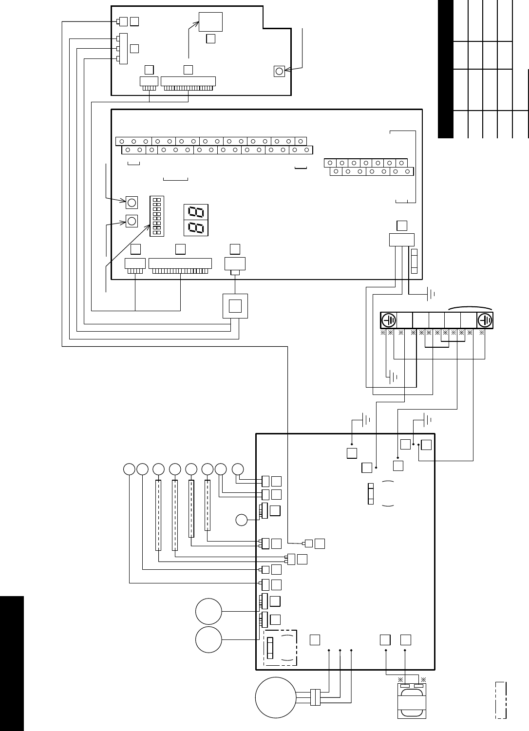
6.8 Wiring Diagrams
:Not available for the model without FUSE CF7
GR
GR
COMPRESSOR
U
(R)
V
(S)
W
(T)
R
BL
R
B
W W
B B
B B
W
B
W(T)
V(S)
U(R)
9
8
7
OR
Y
REACTOR
FUSE CF2
250V
T3.15A
FUSE CF7
250V
T3.15A
18
MOTOR
(FAN)
PUMP
17
EXP.V.
23
34 33
28
32
31 10 11
PCB
(MAIN)
SENSOR(TEMP., SUCTION)
SENSOR(TEMP., DEFROST)
SENSOR(TEMP., DISCHARGE)
SENSOR(TEMP., OUTDOOR)
SENSOR(TEMP., OUTGOING)
4 WAY V.
DEFROST HEATER
SENSOR(TEMP., RETURN)
B
W
3
4
2
1
6
8
6
4
ON
OFF
TERMINAL BLOCK
GR
BL
W
R
W
B
B
B
G/Y
BL Y B
R
G/Y
WN
LPOWER
1
2
3
PCB
(CONTROLLER)
PCB
(TERMINAL)
7
3
4
5
TRANSFORMER
2
1
Remote
Controller
1
2
3
4
5
6
7
17
18
19
20
21
22
23
Humidity
Sensor
COM
DHW Remote
Contact
ON/OFF
or
EHS Alarm
GND
24VAC
COM
Control
DHW
T.probe
OUTDOOR
T.probe
BUFFER
T.probe
Mix water
T.probe
3-way
mixing
valve
RS485
+
-
Dehumidier
Alarm
Pump1
Pump2
Neutral
N.C.
Neutral
EHS
Phase
Signal
3-way
valve
8
9
10
11
12
13
14
Dual Set
Point
Control
Heating
Cooling
mode
Flow
switch
Night
mode
Low
tari
RS485
GND
45
46
47
48
49
50
31
32
24
25
26
27
28
29
30
15
16
N
41
42
43
44
51
52
Electric
heater
RESET SW.
PUMP SW.
RAM CLEAR
EEPROM
DIP SW.
FUSE CF1
(250V T10A)
Heating
Cooling
mode
output
Figure 6-8: HPID6 and HPID10 circuit diagram
Colour of wires
B Black BL Blue
W White GR Grey
R Red OR Orange
G Green Y Yellow
BR Brown
Section 6: Electrical Page 29
PCB
(MAIN)
H.P.SW.
EXP.V.
4 WAY V.
DEFROST HEATER
SENSOR
(TEMP.,SUCTION)
SENSOR
(TEMP.,DISCHARGE)
28
25
21
23
19
13 14
8
11
6
4
22
29
89
MOTOR
(FAN)
MOTOR
(FAN)
upper
lower
SENSOR
(TEMP.,DEFROST)
ON
OFF
PUMP
UVW
W V U
R W B
OR
Y
Y
OR
COMPRESSOR
OHR
TERMINAL BLOCK
REACTORREACTOR
FUSE CF2
(250V T5A) GR
GR
B
BL
3
2
1
FUSE CF6
(250V T3.15A)
FUSE CF7
(250V T3.15A)
B
B
B
B
BL
W
B
W
R
W
B
B
B
G/Y
B Y BL
R
G/Y
WN
LPOWER
1
2
3
PCB
(CONTROLLER)
PCB
(TERMINAL)
7
3
4
4
5
TRANSFORMER
2
1
Remote
Controller
1
2
3
4
5
6
7
17
18
19
20
21
22
23
Humidity
Sensor
COM
DHW Remote
Contact
ON/OFF
or
EHS Alarm
GND
24VAC
COM
Control
DHW
T.probe
OUTDOOR
T.probe
BUFFER
T.probe
Mix water
T.probe
3-way
mixing
valve
RS485 +
-
Dehumidier
Alarm
Pump1
Pump2
Neutral
N.C.
Neutral
EHS
Heating
Cooling
mode
output
Phase
Signal
3-way
valve
8
9
10
11
12
13
14
Dual Set
Point
Control
Heating
Cooling
mode
Flow
switch
Night
mode
Low
tari
RS485
GND
45
46
47
48
49
50
31
32
24
25
26
27
28
29
30
15
16
N
41
42
43
44
51
52
Electric
heater
RESET SW.
PUMP SW.RAM CLEAR
EEPROM
DIP SW.
FUSE CF1
(250V T10A)
R
SENSOR
(TEMP., OUTDOOR)
SENSOR
(TEMP., OUTGOING)
SENSOR
(TEMP., RETURN)
R
BW
W
B
Figure 6-9: HPID16 circuit diagram
Colour of wires
B Black BL Blue
W White GR Grey
R Red OR Orange
G Green Y Yellow
BR Brown
Section 6: ElectricalPage 30
6.9 System Control Wiring Diagrams
Figure 6-10: S-plan system connection diagram
Terminals
18 and 19 Hot water
20 and 21 Heating
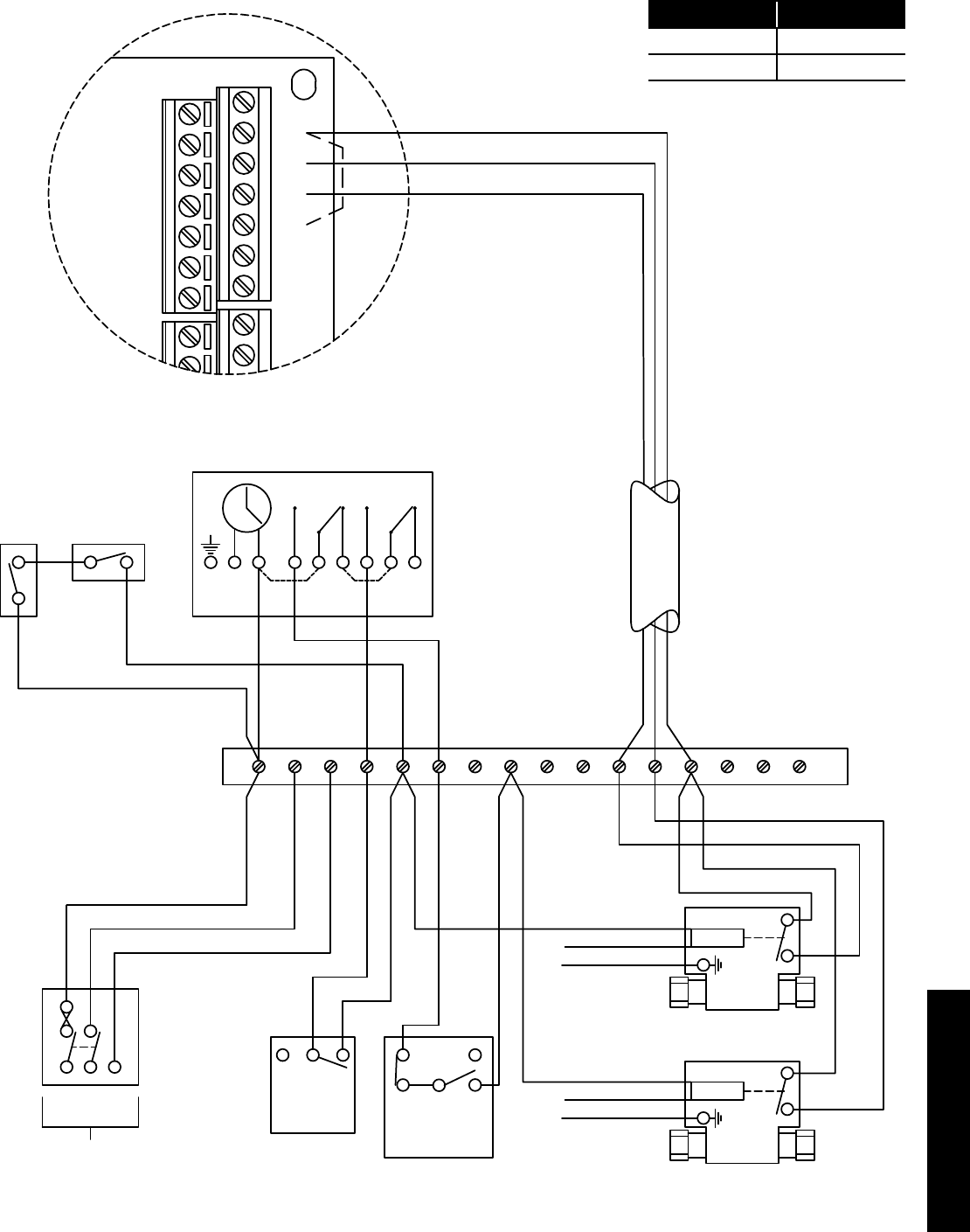
Section 6: Electrical Page 31
Figure 6-11: S-plan (HW priority) system connection diagram
L N E
240V
50HZ
5A
1 2 345678 9 10
Frost
Stat
Pipe Stat
(If fitted)
Wiring Centre
2 1 3
Room
Stat
Brown
Blue
Green/Yellow
2-Port Zone Valve
2-Port Zone Valve
Motor HW
HTG
Blue
Green/Yellow
Motor
Blue
Green/Yellow
Orange
Orange
Brown
Brown
17
18
19
20
21
22
23
24
25
1
2
3
4
5
6
7
8
11 12 13 14 15 16
Grey
Grey
Orange (Yellow)
Grey (Red)
Orange (Blue)
4 Core ( 3 + E )
Volt free connections
from Heating and Hot
Water Zone Valves to
Terminals 18 - 20 on
ASHP Terminal PCB
Link
Dual Limit &
Cylinder Stat
2
C
1
HW ON
N L 1 2 34
Horstmann H21 Series 21
E
COMMON
HW OFF
CH ON
COMMON
CH OFF
LINK LINK
Terminals
18 and 19 Hot water
20 and 21 Heating
The control system shown in this diagram ensures that there can be no demand for space heating and hot water at the same time.
In order to achieve this type of operation, the programmer MUST NOT have a built-in connection between the live connection
(driving the timer) and the two programmer switches.
The programmer shown in this diagram is an example of one that meets this requirement, as the installer is required to fit links
between the mains live and the programmer swithces for mains voltage systems.
Section 7: Remote ControllerPage 32
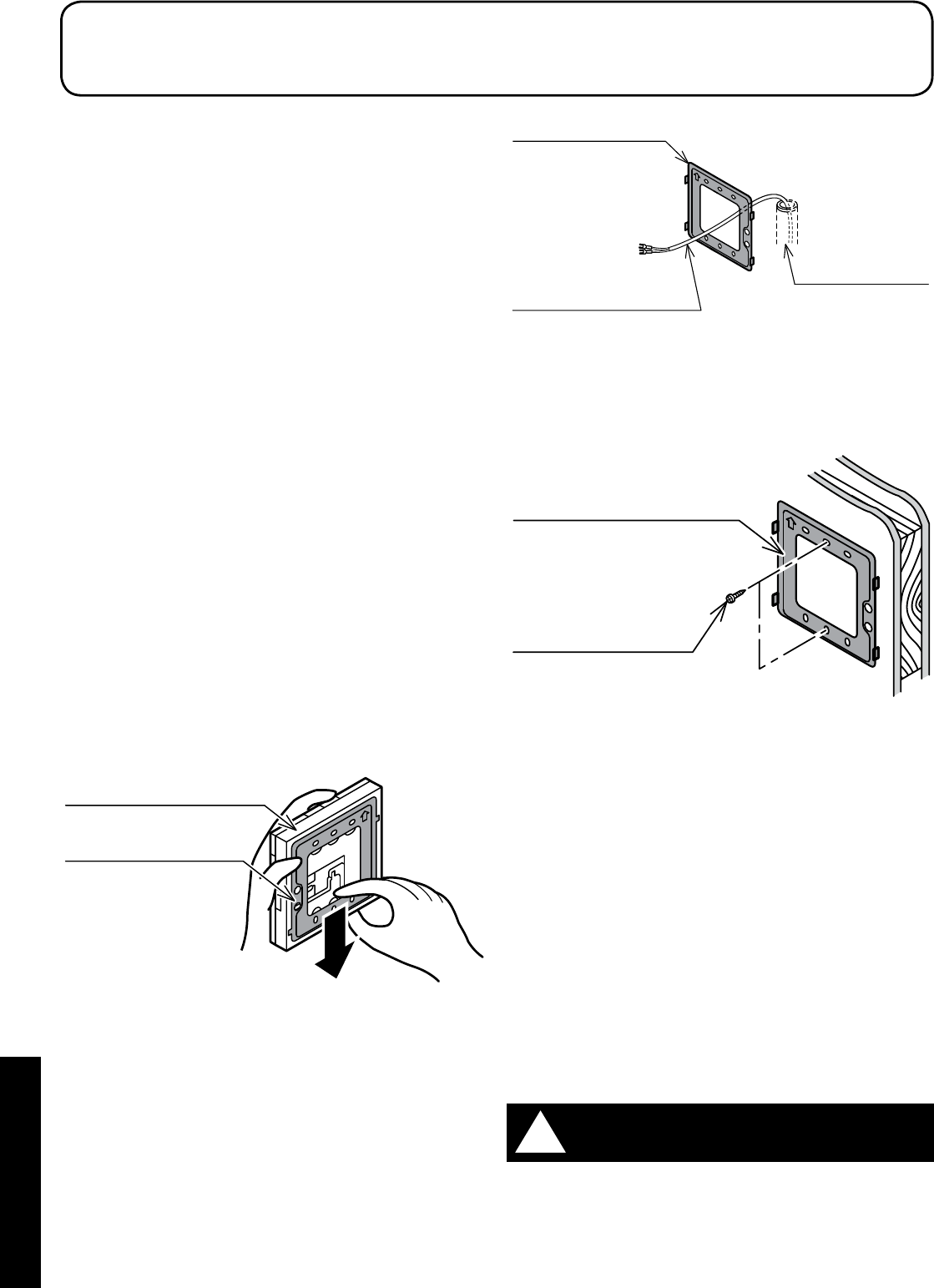
Figure 7-2: Wiring hidden
Wiring conduit
Mounting plate
Remote controller
cord
When the wiring is exposed
1. Fix the mounting plate to a solid position on the wall with the
two screws provided (refer to Figure 7-3).
Screw
Mounting plate
Figure 7-3: Wiring exposed
• Do not over tighten the screws as this can deform or break
the screw hole of the mounting plate.
• Use the wall plugs if the mounting plate is to be fixed by
screws to tile, concrete or mortar.
• The remote controller is connected using the two screw
terminals on the rear of the controller. Refer to Figure 7-5.
3. Connect the remote controller cable to the terminal on the rear of
the remote controller:
1. Hook the wires under the clamp - locating it onto the four
hooks
• The remote controller has no polarity so wires can be
connected either way round.
4. Install the remote controller.
Fix the remote controller to the mounting plate by sliding it
downwards.
5. After installing the remote controller, check the fixing is secure.
If the mounting plate is not stable, tighten the screws further.
Do not use a power screwdriver. It can damage the screw hole
which can cause contact failure.
!WARNING
7.1 Remote Controller
The remote controller is used to switch the heat pump on and off,
display room temperature, outdoor temperature, time, to access and
check/adjust remote controller parameters.
• The connection between the heat pump and the remote
controller is low-voltage, so it does not require electrical
qualifications, but do follow technical standards for electrical
equipment in making this installation.
• Isolate the main power supply to the heat pump before
connecting the remote controller cable.
7.2 Installation Requirements
Notes for the remote controller installation
• Do not install the remote controller in damp conditions such as in
the bathroom. The remote controller is not waterproof
• Never install above a cooker or boiler or any other combustion
device. This would cause breakdown of electrical parts and
deformation of the outer case
• Do not install in any location subject to steam
• Do not install in any location subject to direct sunlight
• Install the remote controller a convenient position where it is out
of the reach of children
• The remote controller can be installed in the same room as
underfloor heating
• Do not install in any location where industrial chemicals are used
(ammonia, sulphur, chlorine, ethylene compounds, acids, etc.)
• Route the remote controller cable in such a way that is not in
contact with heat
• Do not damage the remote controller cable and use cable
conduit to avoid the damage
7.3 Installing the Remote Controller
1. Slide the mounting plate downward to remove from the remote
controller (refer to Figure 7-1).
Remote controller
Mounting plate
Figure 7-1: Removing the mounting plate
2. Fix the mounting plate to the wall.
When the wiring is hidden
1. Before starting the remote controller installation, pass the
wiring conduit through the inside of the wall (refer to Figure 7-2).
2. Pull out the Remote controller cord, passing it through the
wiring conduit and through the wiring hole in the mounting plate.
7 Remote Controller
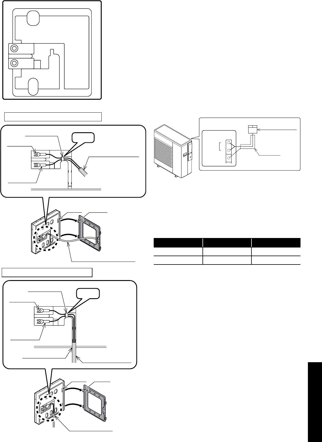
Section 7: Remote Controller Page 33
Remote controller cord
hooks
gaps
wires clamp
Remote controller
cable
Hook
terminal
Y-shaped
terminal
When the wiring is embedded
hooks
gaps
knock out hole Remote controller
cable
knock out hole
wires clamp
terminal
Y-shaped
terminal
Hook
When the wiring is exposed
Figure 7-5: Connecting remote controller cable
7.4 Connecting the Remote Controller to the Heat
Pump
1. Isolate the mains power supply for the heat pump from the power
source.
Do not connect the remote controller cable with the power on.
2. Remove the wiring cover.
3. Connect the remote controller cable to terminals 1 and 2 on the
Terminal PCB. The remote controller has no polarity so it does
not matter which wire of the remote controller cable is connected
to + and -. Take care not to let your screwdriver etc. touch any
of the other electronic parts. Do not use a power driver. It can
damage the terminal screw holes.
4. If shielded wire is used, connect it to terminal 3 (GND) on the
Terminal PCB.
5. Securely fasten the remote controller cable with the cord
fastening fitting. Leave the display board waterproof cover
removed.
Remote controller
Terminal PCB
Remote controller
Shielded cable
Remote
Controller
1
2
DNG 3
Figure 7-6: Connecting the remote controller to the heat pump
An 8 metre cable is supplied with the heat pump.
The maximum length of the remote controller cable is 100 metres.
Use shielded wire where the length is 30 metres or longer and
connect the shielded wire to terminal 3 (GND) on the Terminal PCB.
Table 7-7: Remote controller cable
Distance Cable (mm²) Shield
~ 30 metres Minimum 0.5 Non-shielded
30 ~ 100 metres Minimum 1.0 Shielded
Figure 7-4: Remote controller (rear)
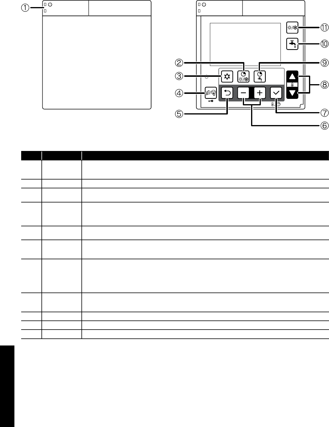
Section 7: Remote ControllerPage 34
7.5 Buttons
Door open
Figure 7-8: Remote controller (buttons)
Table 7-9: Remote controller (buttons)
No. Button name Description
1 ON/OFF
Push and hold the button for 3 seconds to turn ON and turn OFF the heat pump.
The green LED on the ON/OFF button is lit when the heat pump is ON.
The red LED on the ON/OFF button blinks when an error alarm on the heat pump occurs.
2 N/A This button is reserved for future products - pressing this button will result in an audible ‘beep’ indicating no function.
3 Menu Programming: dedicated button for accessing the menu/parameters.
Push and hold the Menu button for 3 seconds to access the user level.
4
Timer for low tariff/
night mode
(key lock)
Refer to Sections 8.6 and 8.7 for details of low tariff/night mode operation.
Push the Low tariff/Night button for 3 seconds to lock the button. When Key Lock is active, push 3 seconds to unlock.
When key Lock is active, it is only possible to turn OFF the heat pump with the ON/OFF button.
For low tariff/night mode function, an external timer must be connected.
5 Return Return button in parameter programming mode.
Push the Return button for 3 seconds to return to the normal display mode.
6 -,+
For parameter setting, select or return to the parameter group or code.
Push the Menu,–,+ button together for 3 seconds to access the installer level.
During error code display, push – and + button together for 3 seconds to reset display.
7 Set (confirm)
Push the Set button:
-During the programming to save the setting.
-Change display : Clock → Room set temperature
Time setting can be set by remote controller only
Push the Set button for 3 seconds to set the current time (day, hour, minutes).
Refer to Section 9 (Commissioning)
8 Up, down
For parameter setting, change the parameter group and code numbers.
Please note: this is not to be used for setting the room temperature control.
9 N/A This button is reserved for future products - pressing this button will result in an audible ‘beep’ indicating no function.
10 N/A This button is reserved for future products - pressing this button will result in an audible ‘beep’ indicating no function.
11 N/A This button is reserved for future products - pressing this button will result in an audible ‘beep’ indicating no function.
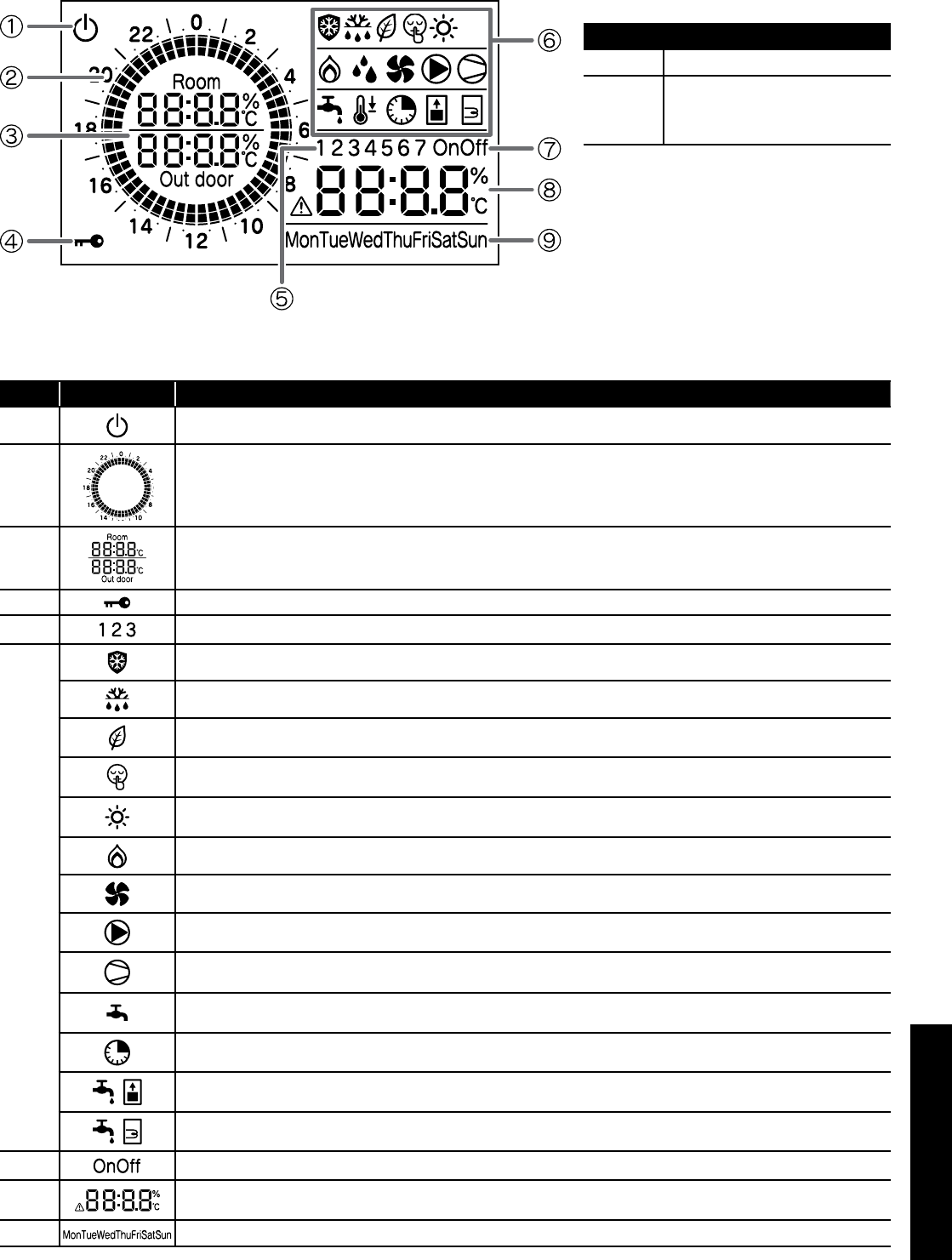
Section 7: Remote Controller Page 35
7.6 Display Panel
For guidance on the operation and setting of the remote controller, refer to Section 9 (Commissioning).
Table 7-11: Display panel
No. Icons Description
1Power is ON, but ON/OFF switch is OFF (the heat pump is stopped)
2Indicates current time of day.
3 Room air temperature, Outdoor temperature
4 Key lock is active
5Display in time band setting
6
Frost protection is active
Defrost cycle is active
Low tariff mode is enabled*
Night mode is enabled*
When this symbol is lit, heating mode is enabled. When this symbol is flashing, the heat pump is in heating mode, however the
heating is stopped for the production of DHW which has priority
Not available
Heat pump fan is active
System pump is active
Compressor active
Flashing: compressor delay
Indicates DHW demand
On: demand
Not available
Not available
Not available
7Not available
8Display alarm icon, and indicate error code
Clock, Parameters value
9 Day of the Week
* For low tariff/night function , an external timer must be connected. Refer to Section 6.
Table 7-11: Back light display
Back light display
ON Door of remote controller open
OFF
Door of remote controller closed
or
Door of remote controller open but no
operation of buttons for 60 seconds
To adjust the back light operation, refer to Section
9.9.
Figure 7-10: Remote controller (display panel)
Section 8: OperationPage 36
8.1 Heat Pump Operation
The heat pump control is based on:
1. Outgoing water temperature (measured by outgoing water
temperature sensor on heat pump)
2. Thermal store temperature
During heating operations, parameter 4100 is set to 1. The control of
the heat pump is based on the outgoing water temperature.
The operation by water temperature can be “outgoing water
temperature” or “thermal store temperature”. If parameter 5111 is
set to “enable” for thermal store temperature sensor. In this case the
operation will be based on thermal store temperature.
Set the parameter correctly for enable/disable of thermal store
(parameter 5111), the main water pump setting (parameter 4200).
Refer to Table 8-1.
Table 8-1: Parameters
Parameter 5111
thermal store
temperature
Parameter 4100
heat pump ON/
OFF
Parameter 4200
main water
pump
Outgoing water
temperature 0=disable 1=Water set
point
0=always ON
2=detect cycle
Thermal store
temperature 1=enable 0=room set
point
0=always ON
1=thermal store
temperature
2=detect cycle
For further information, refer to Section 3.8 (buffer tanks).
8.1.1 Heat Pump controlled based on Outgoing Water
Temperature
Based on the outgoing water temperature setting, the compressor is
controlled and turned ON/OFF.
Start of Operation
When the outgoing water temperature is below the water set point, the
heat pump is turned ON.
Heating : Outgoing water temp ≥ Water set point (parameter
2100~2105) – Hysteresis (parameter 2141)
Compressor Control
The compressor is controlled so that the Outgoing water temperature
can reach the water set point.
When the water setpoint temperature is reached, compressor
is stopped
With the minimum compressor frequency, if the Outgoing water
temperature is in the following conditions, or if the Outgoing water
temperature reaches the water set point to protect heat pump, then
compressor shall be turned OFF.
Table 8-2: Parameters
Level Parameter Function description Display and input value Remarks
Group Code Default Min. Max. Unit
I 41 00 The heat pump turns ON/OFF based on
1=water set point 1 0 1 - To be set to
the following
combinations
parameter 5111=0
→Parameter
4200=0 or 2
parameter 5111=1
→Parameter
4200=0 or1 or 2
I 42 00 Type of configuration of main water pump
0=always ON 0 0 0 -
I 51 11
Terminal 11-12: thermal store temperature probe
0=disable
1=enable
0 0 1 -
For details of how to access the parameter settings, refer to Section 9.3.
Heating : Outgoing water temp. ≥ Water set point (parameter
2100~2115) +1°C
Outgoing water temp. ≥ 60.5°C
Compressor OFF→ON control
When the Outgoing water temperature reaches the set point and after
the compressor is turned OFF, or when the conditions below are met,
the compressor shall be turned ON.
However, the compressor is not turned ON during 3 minutes OFF-ON
waiting time.
8.1.2 Heat Pump controlled based on Thermal Store
Temperature
In order to reach the thermal store set point, compressor frequency
shall be controlled so that outgoing water temperature can reach the
maximum temperature in Heating mode (60°C) And, the compressor
is turned ON/OFF based on thermal store set point also being
reached.
Start of Operation
When the Outgoing water temperature does not reach the water set
point, heat pump is turned ON.
Compressor Control
The compressor is controlled to reach the maximum flow temperature
in Heating mode (60°C).
When the water set point is reached, compressor is stopped
The compressor shall be turned OFF if the thermal store set point
is reached, or if the Outgoing water temperature is in the following
conditions, or the Outgoing water temperature reaches the set point to
protect heat pump.
Heating: thermal store temperature ≥ thermal store set point
(parameter 2161)
Outgoing water temp. ≥ Maximum Outgoing water set point (60°C)
+1°C
Outgoing water temp. ≥ 62.5°C
Compressor OFF→ON control
When the thermal store temperature reaches the set point, or when
the conditions below are met after the compressor is turned OFF due
to the set point protecting the heat pump, the compressor is turned
ON.
However, the compressor is not turned ON during 3 minutes OFF-ON
waiting time.
Heating: thermal store temp. ≤ thermal store set point (parameter
2161) – Hysteresis (Parameter 2141)
Outgoing water temp. ≤ Water set point (60°C) – Hysteresis
(parameter 2141)
Outgoing water temp. ≤ 57.5°C
8 Operation
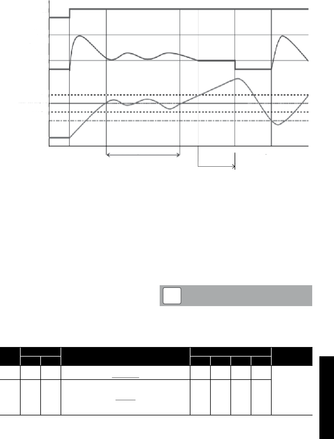
Section 8: Operation Page 37
Based on Water Temperature
Heating mode
Heat pump
Maximum
Compressor (Hz)
set temp. + 1
set temp. - 1
Water set temp. (°C)
set temp. - Hysteresis
Heating ON Water temperature is stable
minimum
ON
OFF
OFF
Comp. OFF → ON
set point + 1°C
× 3min
Comp. OFF
8.2 Water Pump Management
8.2.1 Main water pump
Fundamentally, the ON/OFF of the main water pump links to ON/
OFF of the compressor, but the setting ON/OFF of the pump during
compressor OFF states, due to reaching the room set point shall be
set in the following parameters:
• Always ON, apart if any alarms are active or if the heat pump is
in OFF mode
• ON/OFF based on thermal store temperature
• ON/OFF based on detect cycle
If the thermal store temperature probe is enabled, the main water
pump turns ON if the thermal store temperature is lower than outgoing
water set point (fixed or calculated by climatic curve) – hysteresis, in
heating mode. When the thermal store temperature reached the set
point (fixed or calculated by climatic curve), the main pump turns OFF.
8.2.2 Continuous operation “Always ON”
When the heat pump is set to “heating” (i.e. not in standby) the main
water pump will always remain ON.
When the heat pump is set to standby, the pump will remain OFF and
will only be started in the conditions described in paragraph in Section
8.3 (Frost protection).
Table 8-4: Main water pump parameters
Level Parameter Function description Display and input value Remarks
Group Code Default Min. Max. Unit
I 42 00 Type of configuration of Main water pump
0=Always ON 0 0 2 - To be set to
the following
combinations
parameter 5111=0
→Parameter
4200=0 or 2
parameter 5111=1
→Parameter
4200=0 or1 or 2
I 51 11
Terminal 11-12 : thermal store temperature probe
0=disable
1=enable
0 0 1 -
For details of how to access the parameter settings, refer to Section 9.3.
8.2.3 Detect operation “Detect cycle”
In order to minimise energy consumption, the main water pump
can be configured to start only when there is demand from the
temperature controller.
The pump will be activated periodically, for a time set by parameter.
Five seconds before the cycle ends, if the outgoing water temperature
is lower than “water set point – hysteresis”, the compressor will be
activated and the pump will remain ON. When the compressor stops,
the pump will continue running for a time set by parameter, after
which it will be switched OFF and will repeat the detect cycles.
The interval between one detect cycle and the next is set by a
parameter.
Refer to Figure 8-5.
The ‘detect cycle’ is allowed only for space Heating. If the heat
pump is working to produce DHW the main water pump has to
run continuously.
NOTE
!
Figure 8-3: Based on water temperature
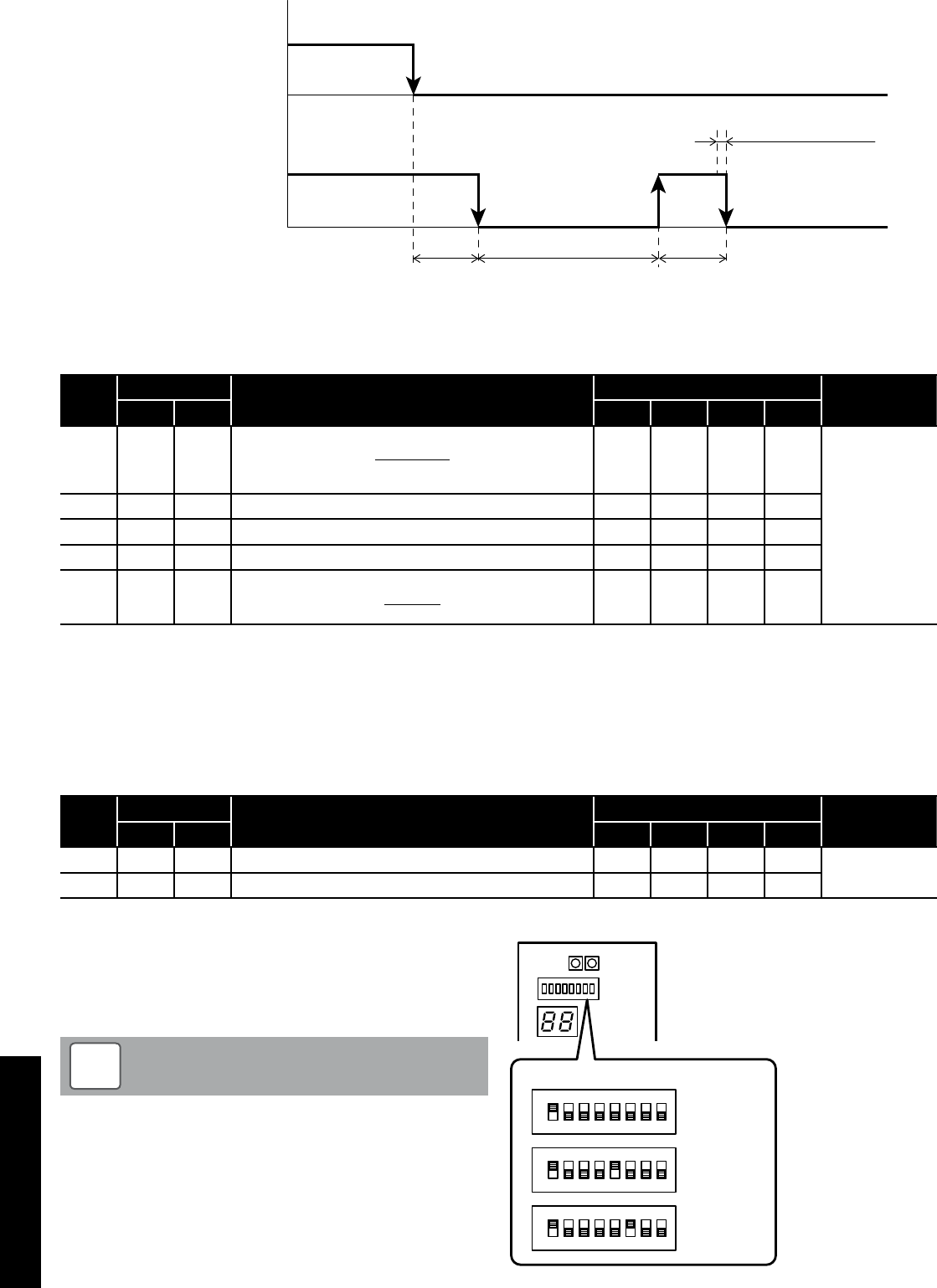
Section 8: OperationPage 38
Delay time
OFF
Time OFF Time ON
(3min) (5min) (3min)
(5sec)
Water temp. detect
Compressor ON
OFF
Main water pump ON
OFF
Figure 8-5: Detect cycle
Table 8-6: Detect cycle parameters
Level Parameter Function description Display and input value Remarks
Group Code Default Min. Max. Unit
I 42 00
Type of configuration of Main water pump
0=always ON
1=ON/OFF based on thermal store temperature
2=ON/OFF based on Detect
0 0 2 - To be set to
the following
combinations
Parameter 5111=0
→Parameter
4200=0 or 2
Parameter 5111=1
→Parameter
4200=0 or1 or 2
I 42 01 Time ON main water pump for detect cycle 3 1 15 1min
I 42 02 Time OFF main water pump 5 5 30 1min
I 42 03 Delay time OFF main water pump from OFF compressor 3 1 15 1min
I 51 11
Terminal 11-12 : thermal store temperature probe
0=disable
1=enable
0 0 1 -
For details of how to access the parameter settings, refer to Section 9.3.
8.2.4 Unblock pump function
When the heat pump is stopped for more than 48 hours, the water
pump turns ON for few seconds to prevent seizing up and increases
the life time of the pump.
In the case of the main pump and the additional pump, the down time
after the previous operation stop is counted individually. Furthermore,
the pump operation time can be set individually to prevent seizing.
Level Parameter Function description Display and input value Remarks
Group Code Default Min. Max. Unit
I 42 11 OFF time for unblock pump function start 48 0 240 1hr
I 42 12 Time ON main water pump for unblock pump function 5 0 10 1sec
Table 8-7: Unlock pump function parameters
8.2.5 Pump output adjustment function
Adjust the main water pump output so that the required flow rate is
produced in the heating system.
Using the DIP SW on the Terminal PCB, three level settings are
possible.
An excessively low flow rate may cause problems including
reduced capacity and poor circulation.
NOTE
!
To select one of the three performance curves, set DIP SW5 and DIP
SW6 as shown in Figure 8-8.
Factory default setting:
DIP SW5 and DIP SW6 set to OFF (level 3)
ON
OFF
DIP SW.
Level 3
(Maximum)
ON
OFF
Level 2
(Medium)
ON
OFF
Level 1
(Minimum)
1 2 3 4 5 6 7 8
1 2 3 4 5 6 7 8
1 2 3 4 5 6 7 8
Figure 8-8: Pump output adjustment flow rate - dip switches
Section 8: Operation Page 39
0
1
2
3
4
5
6
7
8
9
10
11
12
(m)
0 5 10 15 20(L/min)
Level3
Level2
Level1
HPID6
Figure 8-9: Pump output adjustment flow rate - HPID6
0
1
2
3
4
5
6
7
8
(m)
0 105 20
15 25 30 35 40(L/min)
Level3
Level2
Level1
HPID10
Figure 8-10: Pump output adjustment flow rate - HPID10
0
2
4
6
8
10
12
14
(m)
0 10 20 30 40
Level3
Level2
Level1
50(L/min)
HPID16
0
2
4
6
8
10
12
14
(m)
0 10 20 30 40
Level3
Level2
Level1
50(L/min)
Figure 8-11: Pump output adjustment flow rate - HPID16
The water flow rate must be sufficient to achieve an 8K
difference between the flow and return water temperatures.
!CAUTION
8.2.6 Additional water pump
Parameter 5148 can be utilised to use an additional water pump.
Parameter 4220 can be used to set the desired type of pump
operation as follows:
1. Depending on main water pump setting
2. Depending on main water pump setting but always OFF when
DHW mode is activated
3. Always ON apart from if any alarms are active or if the heat pump
is in OFF mode
Option 2 is recommended for the majority of applications.
The connection between neutral and terminal 48 (Pump1) is limited to
1 amp, therefore a relay must be installed if an additional water pump
is used. Refer to Figure 8-12.
In reference to option 3 above (and parameter 4220 in Table
8-13), ‘OFF’ mode means there is a power supply to the heat
pump but there is no heating or hot water demand.
NOTE
!
Additional water pump
230V 50Hz
P
Terminal PCB
Dehumidier
Neutral
EHS
45
46
47
48
49
N
41
42
43
44
Electric
heater
Heating
Cooling
mode
output
Alarm
Pump1
Pump2
Figure 8-12: Additional water pump
Table 8-13: Additional water pump parameters
Level Parameter Function description Display and input value Remarks
Group Code Default Min. Max. Unit
I 51 48
Terminal 48
0=disable
1=additional water pump
0 0 1 -
I 42 20
Type of operation of additional water pump
0=disable
1=depending on main water pump setting
2=depending on main water pump setting but always OFF when
the DHW mode is activated
3=always ON, apart from if any alarms are activated or if the
heat pump is in OFF mode
0 0 3 -
For details of how to access the parameter settings, refer to Section 9.3.
Section 8: OperationPage 40
8.3 Frost Protection
Frost protection can be activated when the heat pump is in OFF
mode.
This is based on either:
• Outdoor air temperature
• Outgoing water temperature
8.3.1 Frost Protection based on Outdoor Air Temperature
The frost protection function is always active, even when the heat
pump is not operating (but the mains supply is switched on). The
water pump is activated if the outdoor air temperature (measured
by the heat pump outdoor temperature sensor) is less than the start
temperature - parameter 4311 (default: 4°C). It is deactivated when
the outdoor air temperature reaches ‘outdoor air temperature set point
+ Hysteresis’ - parameter 4311 plus the hysteresis parameter 4312
(default: 7°C).
(3.0°C)
hysteresis
Backup heater
Flow water temperature
Backup heater ON
OFF
(4.0°C)
Backup heater
set point
(3.0°C)
(4.0°C)
start temperature
hysteresis
Water pump deactivation
Outdoor air temperature
(HP unit built-in sensor)
Water pump ON
OFF
Figure 8-14: Frost protection - water pump
Figure 8-15: Frost protection - backup heater
Table 8-16: Frost protection (outdoor air temperature) parameters
Level Parameter Function description Display and input value Remarks
Group Code Default Min. Max. Unit
I 43 11 Start temperature of Frost protection on Outdoor air temperature 4.0 0.0 10.0 0.5°C
I 43 12 Hysteresis of Outdoor air temperature 3.0 0.5 5.0 0.5°C
I 43 13 Backup heater set point during Frost protection 4.0 0.0 10.0 0.5°C
I 43 14 Hysteresis of Flow water temperature 3.0 0.5 5.0 0.5°C
I 51 46
Terminal 46 : DHW Electric heater or Backup heater
0=DHW Electric heater
1=Backup heater
0 0 1 -
For details of how to access the parameter settings, refer to Section 9.3.
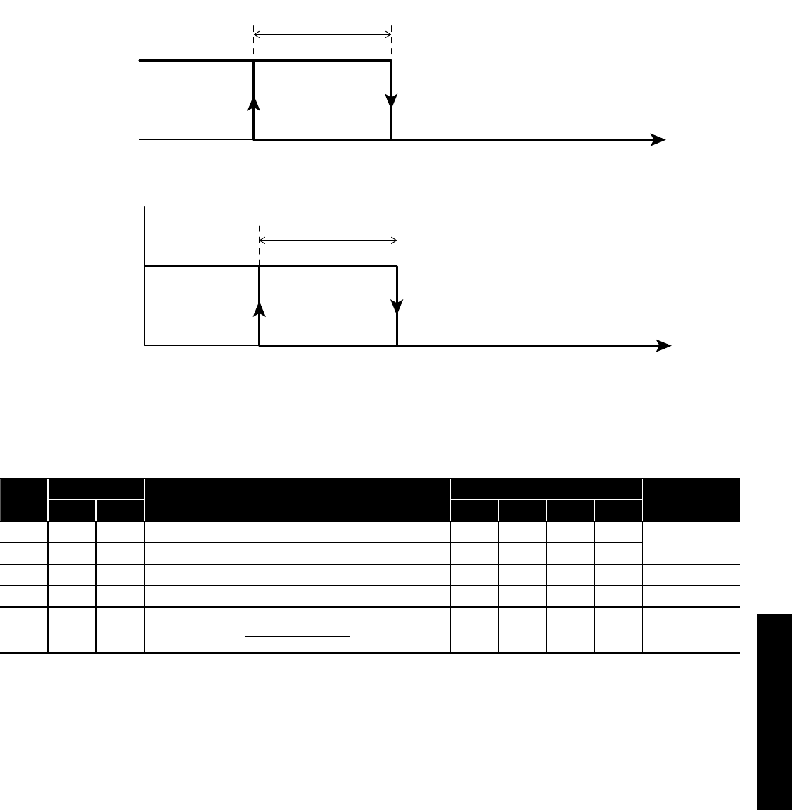
Section 8: Operation Page 41
8.3.2 Frost Protection based on Flow Water Temperature
The frost protection function is always active, even when the heat
pump is not operating (but the mains supply is switched on).
The water pump is activated if the flow water temperature is less than
the start temperature - parameter 4321 (default 4°C) and deactivated
when the flow water temperature reaches ‘flow water temperature set
point (parameter 4321) + hysteresis - parameter 4322 (default 3°C)’
(3.0°C)
(4.0°C)
hysteresis
Backup heater
Flow water temperature
Backup heater ON
OFF
Backup heater
set point
(3.0°C)
(4.0°C)
start temperature
hysteresis
Water pump deactivation
Flow water temperature
Water Pump ON
OFF
Figure 8-17: Frost protection - water pump
Figure 8-18: Frost protection - backup heater
Table 8-19: Frost protection (flow water temperature) parameters
Level Parameter Function description Display and input value Remarks
Group Code Default Min. Max. Unit
I 43 21 Start temperature of Frost protection on Flow water temperature 4.0 0.0 10.0 0.5°C
I 43 22 Hysteresis of Flow water temperature 3.0 0.5 5.0 0.5°C
I 43 13 Backup heater set point during Frost protection 4.0 0.0 10.0 0.5°C
I 43 14 Hysteresis of Flow water temperature 3.0 0.5 5.0 0.5°C
I 51 46
Terminal 46 : DHW Electric heater or Backup heater
0=DHW Electric heater
1=Backup heater
0 0 1 -
For details of how to access the parameter settings, refer to Section 9.3.
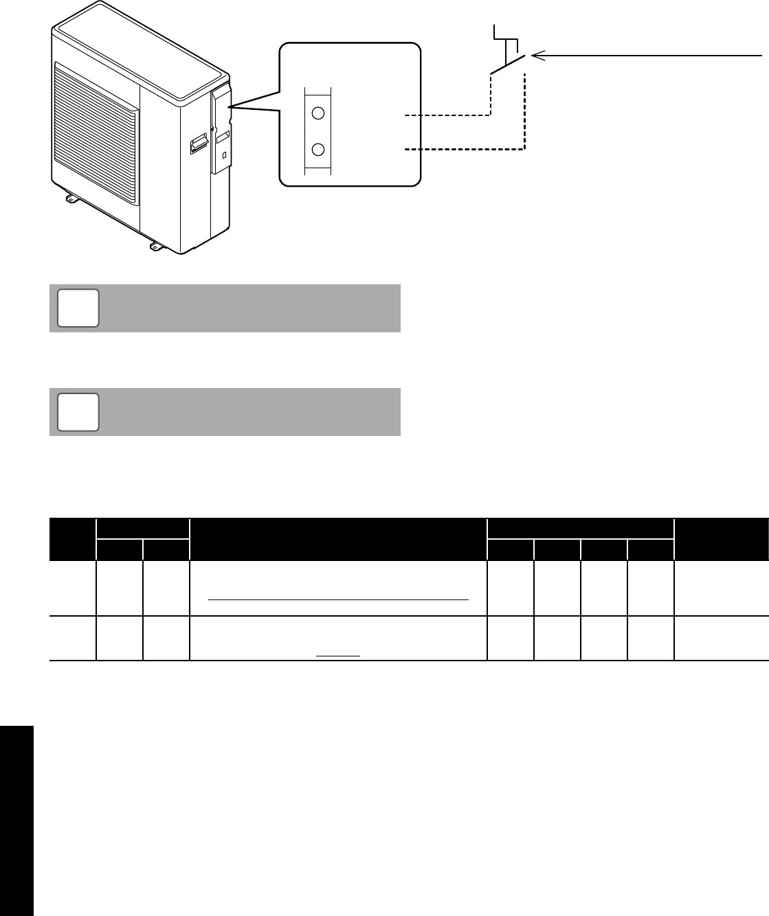
Section 8: OperationPage 42
8.4 ON/OFF DHW Production Remote Contact
The heat pump operation for DHW production is controlled from a
remote contact, e.g. a cylinder thermostat or motorised valve switch.
The remote ON/OFF DHW contact is enabled by parameter
5119. Refer to Table 8-21. The DHW mode cannot be controlled
automatically by the remote controller.
When DHW is turned ON by the remote contact and the heat pump is
ON it will start operation in DHW (comfort) mode.
DHW ON/OFF remote contact
Contact OPEN = DHW OFF
Contact CLOSE = DHW ON
(Comfort)
18
19
Terminal PCB
COM
DHW Remote
Contact
In order to use DHW function, it is necessary to set parameter
3101=1 and parameter 5119=1.
NOTE
!
Figure 8-20: ON/OFF DHW production remote contact
Turn ON both remote controller using ON/OFF but ton, and
DHW ON/OFF remote contact to start heat pump for DHW.
NOTE
!
Table 8-21: DHW ON/OFF contact parameters
Level Parameter Function description Display and input value Remarks
Group Code Default Min. Max. Unit
I 31 01 DHW production priority setting
0=DHW is unavailable
1= DHW is available, and priority DHW over space heating
2= DHW is available, and priority space Heating over DHW
1 0 2 -
I 51 19 Terminal 19-18 : DHW remote contact
0=disable (Remote controller only)
1=enable
1 0 1 -
For details of how to access the parameter settings, refer to Section 9.3.
Section 8: Operation Page 43
ON/OFF remote contact
Contact OPEN = HP unit OFF
Contact CLOSE = HP unit ON
20
21
Terminal PCB
ON/OFF
or
EHS Alarm
8.5 ON/OFF Heating Remote Contact
The heat pump operation for heating is controlled from a remote
contact, e.g. an external programmer, motorised valves and/or a
room thermostat.
The ON/OFF heating contact is enabled by parameter 5120. Refer to
Table 8-23.
The heating operation cannot be automatically controlled by the
remote controller.
Heat pump will be turned ON/OFF according to remote contact.
For heating operation, both the remote controller and remote contact
must be ON. If remote contact is turned OFF, then the heating will be
turned OFF as well. Refer to Table 8-23.
If the remote controller is turned OFF, then the heat pump will be
turned OFF.
Figure 8-22: ON/OFF heating remote contact
Table 8-23: Heating ON/OFF contact parameters
Level Parameter Function description Display and input value Remarks
Group Code Default Min. Max. Unit
I 51 20 Terminal 20-21 : ON/OFF remote contact input
0=disable (Remote controller only)
1=ON/OFF remote contact
2=EHS Alarm input
1 0 2 - ON/OFF by
Remote controller
0=enable
1= On/Off enable
2= enable
For details of how to access the parameter settings, refer to Section 9.3.
Table 8-24: Remote controller / remote contact operation
Remote controller connected Heat pump unit status
Remote controller Remote contact Heat pump Heating
ON ON →ON ON
ON OFF →ON* OFF
OFF ON →OFF OFF
OFF OFF →OFF OFF
* Heat pump will be on standby or could be operating for DHW production
The frost protection is active even when the heat pump is
switched OFF from the ON/OFF (heating) remote contact.
NOTE
!
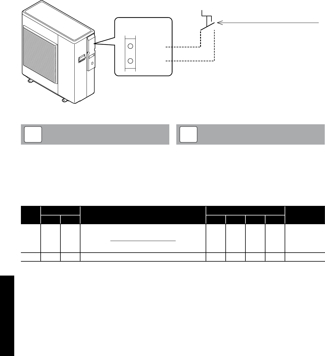
Section 8: OperationPage 44
8.6 Night Mode
If there is a need to reduce the electricity consumption or noise
produced by the compressor, e.g. in night-time operation, it is
possible to activate the night mode function using an external
contact, e.g. a timeswitch (with volt free contacts) connected between
terminals 28-29 on the PCB terminal.
To enable these terminals, parameter 5128 must be set to 1. Refer to
Table 8-26.
When the night mode function starts, according to the time setting,
the maximum frequency will be decreased to the value selected on
parameter 4111 in the ON time by time band setting (refer to Table
8-26). Otherwise it will operate in normal mode.
Night mode contact
Contact OPEN = Night mode OFF
Contact CLOSE = Night mode ON
28
29
Terminal PCB
Night
mode
Figure 8-25: Night mode
Parameter 5128 (night mode) and parameter 5130 (low tariff are
automatically synchronized to same value.
If parameter 5128 is changed to 1 (enable), then parameter
5130 will be also changed to 1 (enable).
With parameters 5128 and 5130 both set to 1 (enable), the night
mode and low tariff function will operate independently of each
other.
NOTE
!
During night mode with night mode contact ON, if parameter
5128 is changed to 0, the heat pump will continue to operate in
night mode.
During night mode by the remote controller button, if
parameter 5128 is changed to 1, the heat pump will follow the
signal of ON/OFF by night mode contact.
NOTE
!
Table 8-26: Night mode parameters
Level Parameter Function description Display and input value Remarks
Group Code Default Min. Max. Unit
I 51 28
Terminal 28-29 : Night mode
0=disable (Remote controller only)
1=enable
0 0 1 -
Parameter 5128
and parameter
5130 are
synchronized in
same value
I 41 11 Maximum frequency of Night mode 80 50 100 5%
For details of how to access the parameter settings, refer to Section 9.3.
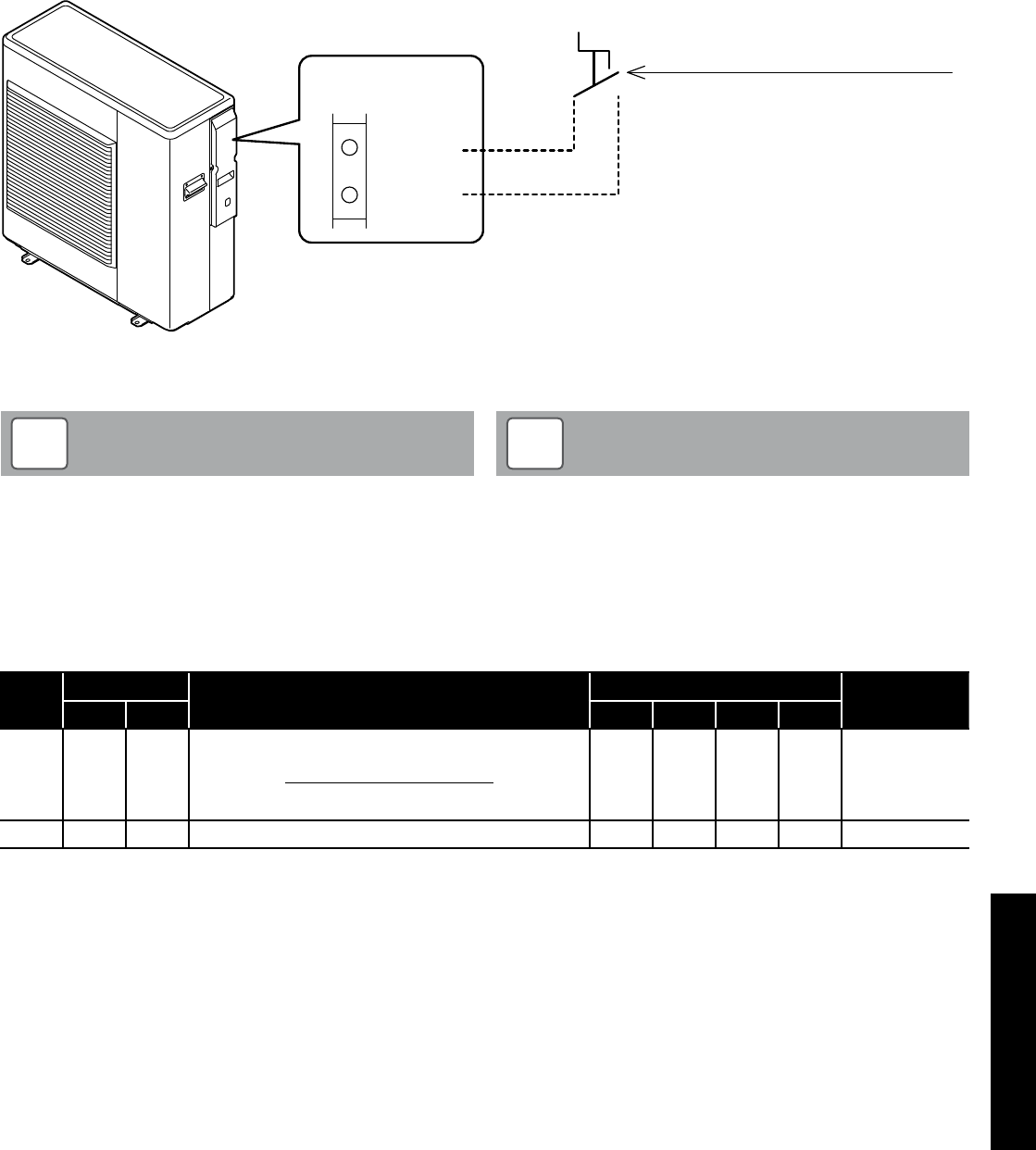
Section 8: Operation Page 45
8.7 Low Tariff
The purpose of this function is to heat any thermal stores and DHW
cylinders at a time when electricity rates are inexpensive.
This can be achieved by using an external contact, e.g. a timeswitch
(with volt free contacts) connected between terminals 30-31 on the
PCB terminal.
To enable these terminals, parameter 5130 must be set to 1. Refer to
Table 8-28.
When low tariff function is activated the heating set point (calculated
by the climatic curve) increases for heating (parameter 2151) by the
low tariff differential water set point (refer to Table 8-28).
Low tariff contact
Contact OPEN = Low tariff OFF
Contact CLOSE = Low tariff ON
30
31
Terminal PCB
Low
tariff
Figure 8-27: Low tariff mode
Parameter 5128 (night mode) and parameter 5130 (low tariff)
are automatically synchronized to same value.
If parameter 5128 is changed to 1 (enable), then parameter
5130 will be also changed to 1 (enable).
NOTE
!
During low tariff with low tariff contact ON, if parameter 5130
is changed to 0, the heat pump will continue to operate in low
tariff.
During low tariff by the remote controller button, if parameter
5128 is changed to 1, the heat pump will follow the signal of
ON/OFF by low tariff contact.
NOTE
!
Table 8-28: Low tariff mode parameters
Level Parameter Function description Display and input value Remarks
Group Code Default Min. Max. Unit
I 51 30
Terminal 30-31 : Low tariff
0=disable (Remote controller only)
1=enable
0 0 1 -
Parameter 5128
and parameter
5130 are
synchronized in
same value
I 21 51 Low tariff deferential water set point for Heating 5.0 0.0 60.0 0.5°C
For details of how to access the parameter settings, refer to Section 9.3.
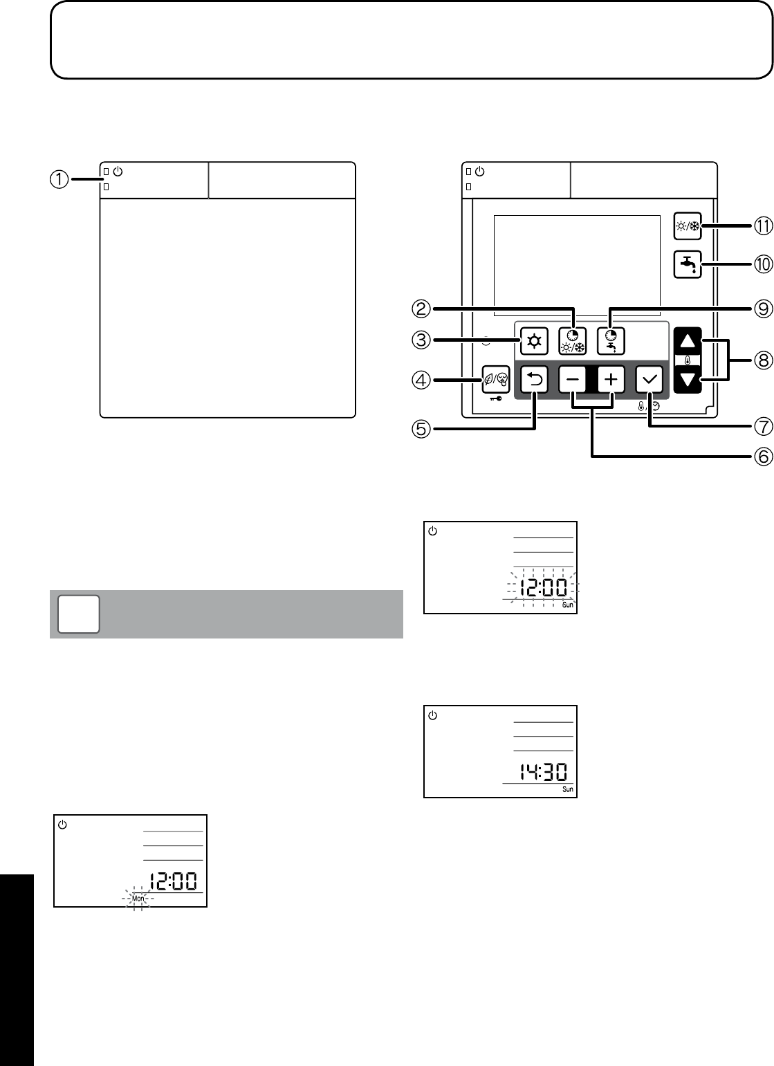
Section 9: CommissioningPage 46
9.1 System Setup
The numbers in Figure 9-1 will be used for the system setup in this
section.
Door open
Figure 9-1: Remote controller buttons
9.1.1 Turning the Heat Pump On and Off
Press
ON/OFF
switch j for three seconds to turn the heat pump on
or off. The green LED of
ON/OFF
switch is lit when the system is ON.
The heat pump will start in response to a demand for either heating or
DHW.
The heat pump may take up to seven minutes after the demand
as the heat pump will run the circulating pump and check the
water temperature in the system before starting.
NOTE
!
9.2 Setting the Day and Time
1. Press the
Set
button p for three seconds.
2. The day ‘Mon’ indicator will blink.
Select the day by pressing the
-
or
+
buttons o and press set
button p to save the setting.
The day display stops blinking.
9 Commissioning
3. When the day of the week is set,
12:00
blinks; set the current
time by pressing the
-
or
+
button.
When the
-
or
+
buttons o is pressed, the time changes in one
minute increments; when the
-
or
+
buttons o is pressed and
held, it changes in ten minute increments.
Press the
Set
button p to save the time setting. Then the display
reverts to normal operation.
The accuracy of the clock is ±30 second/month.
If there is a power cut, the day and time setting is maintained for
approximately 24 hours. If the power cut continues over 24 hours, the
day and time must be reset.
After installation and before setting the time or when the heat pump is
reset after a power cut (lasting over 24 hours), the ‘12:00’ and ‘Mon’
will blink, indicating that the time must be reset.

Section 9: Commissioning Page 47
9.3 Access for Parameter Settings
The parameters are accessed and set using the remote controller.
There are two levels of access for parameter settings.
Access levels:
• U – End user level (accessible to user only)
• I – Installer Level (accessible to user and installer)
Refer to Sections 9.4 and 9.5 for how to access the above levels as
there is a different procedure for each level.
9.4 Accessing the Parameter Setting Menu (User
level)
The procedure for accessing, checking and setting the parameters is
as follows:
1. Press the
Menu
button l on the remote controller for three
seconds to enter the user level.
2. Parameter number “0000” and parameter value “----“ will be
shown on the display.
3. The first two digits of the 4-digit parameter number (the
parameter group number) will blink.
4. Set the parameter group number, as required, using the
Up
or
Down
q buttons.
5. Press the
–
or
+
buttons o to switch to the parameter code and
the second two digits will blink.
6. Set the parameter code number, as required, using the
Up
or
Down
q buttons.
7. Press Set p and the parameter value will be displayed.
For ‘read-only’ items the number displayed remains on (not
blinking) and pressing the
Set
button p does not affect the
display.
8. If an invalid parameter (not accessible to the user) is entered and
the
Set
button p pressed “----“ is displayed. Press the
Return
button n to return to the parameter number.
9. If the parameter value can be adjusted it will blink.
10. Set the parameter to the required value using the
Up
or
Down
q
buttons.
11. Press the
Return
n or
Set
p button. The parameter code
number will blink to allow setting of another parameter, if
required.
12. To return to normal operation, press and hold the
Menu
button l
for three seconds, or simply leave the remote controller for ten
minutes.
9.5 Accessing the Parameter Setting Menu (Installer
level)
In the INSTALLER level more parameters can be accessed than in the
USER level. The procedure for accessing, checking and setting the
parameters is as follows:
1. Press the
Menu
l and the
–
and
+
o buttons on the remote
controller simultaneously for three seconds to enter the installer
level.
2. “InSt” parameter number “0000” and parameter value “----“ will
be shown on the display.
3. The first two digits of the 4-digit parameter number (the
parameter group number) will blink.
4. Set the parameter group number, as required, using the
Up
or
Down
q buttons.
5. Press the
–
and
+
o buttons to switch to the parameter code
and the second two digits will blink.
6. Set the parameter code number, as required, using the
Up
or
Down
q buttons.
7. Press
Set
p and the parameter value will be displayed and will
blink.
8. Set the parameter to the required value using the
Up
or
Down
q
buttons.
9. Press the
Return
n or
Set
p button. The parameter code
number will blink to allow setting of another parameter, if
required.
10. To return to normal operation, press and hold the
Menu
l and
the
–
and
+
o buttons simultaneously for three seconds, or
simply leave the remote controller for ten minutes.
Master Reset (resetting all parameters to their defaults)
All parameters can be reset to their original defaults. The procedure is
as follows:
1. Press the
Menu
l and the
–
and
+
o buttons on the remote
controller simultaneously for three seconds to enter the installer
level.
2. Press and hold the
low tariff/night mode (key lock)
m button for
ten seconds. All parameters will now be reset.
3. To return to normal operation, press and hold the
Menu
l and
the
–
and
+
o buttons simultaneously for three seconds, or
simply leave the remote controller for ten minutes.
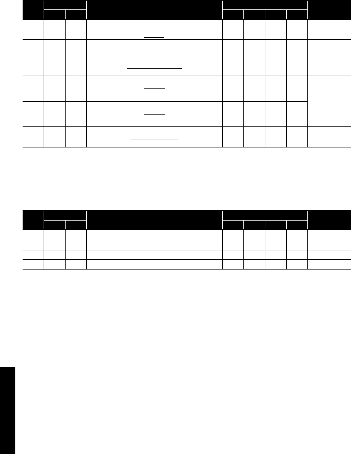
Section 9: CommissioningPage 48
9.6 Parameters Input/Output
The following parameter settings must be checked on commissioning.
Table 9-2: Parameters input/output
Level Parameter Function description Display and input value Remarks
Group Code Default Min. Max. Unit
I 51 19
Terminal 19-18 : DHW remote contact
0=disable (Remote controller only)
1=enable
1 0 1 -
I 51 20
Terminal 20-21 : ON/OFF remote contact (CH)
Alarm input
0=disable
1=ON/OFF remote contact
1 0 1 -
ON/OFF by
Remote controller
0=enable
1=ON/disable
OFF/enable
2=enable
I 51 28
Terminal 28-29 : Night mode*
0=disable
1=enable
Refer to Section 8.6.
0 0 1 - Parameter 5128
and Parameter
5130 are
synchronised in
same value
I 51 30
Terminal 30-31 : Low tariff*
0=disable
1=enable
Refer to Section 8.7.
0 0 1 -
I 51 46
Terminal 46 : DHW Electric heater or Backup heater
0=DHW Electric heater
1=Backup heater
0 0 1 -
* External timer required
For details of how to access the parameter settings, refer to Section 9.3.
9.7 Remote Controller Back Light Display Parameters
The following parameters can be changed to adjust the back light
display.
Table 9-3: Back light display parameters
Level Parameter Function description Display and input value Remarks
Group Code Default Min. Max. Unit
U 02 03
Back light display at door open
0=OFF
1=ON
1 0 1 -
U 02 04 Time to turn off the back light display 60 10 300 10 sec
U 02 05 Time to back to normal display screen 120 10 300 10 sec
For details of how to access the parameter settings, refer to Section 9.3.

Section 9: Commissioning Page 49
9.8 Anti-freeze Function Setting
Refer to Section 3.10.2 and 3.10.3.
9.9 Pump Operation and Air Bleeding from Heating
System
The circulating pump can be operated to aid removal of the air from
the heating system.
To operate this function access the Terminal PCB.
Check DIP SW4 is set to ‘OFF’.
Dip switch positions:
Up: ON / Down: OFF
NOTE
!
Press the Pump SW. Refer to Figure 9-4.
Wait for a few seconds. The pump will start and each of the six outer
digital segments on the right-hand digit of the display on the terminal
PCB will light up sequentially during pump operation.
The pump stops automatically after 10 minutes of operation. If all the
air could not be released from the water circuit, press Pump SW again
(after the pump has stopped) to operate the pump for another 10
minutes.
If you want to stop the pump before it stops automatically, press
Pump SW again.
Display
Pump SW.
Figure 9-4: Water loading and air bleeding in the hydraulic circuit

Section 10: ServicingPage 50
10.1 General
Grant UK Aerona³ Heat Pumps require only the minimum of routine
servicing and maintenance.
This should be carried out on an annual basis and consist of the
following:
Heat pump - check:
• Visual condition of the heat pump
• Any debris/obstructions for the evaporator fins – remove if found
• The fan outlet is not obstructed - remove if found
• Condensate drain opening is clear
• Flexible hose condition
• Pipe insulation condition
• Remote controller settings
• That no refrigerant is leaking
Heating system - check:
• Expansion vessel pressure
• Operation of pressure relief valve
• Heating system pressure – top up if necessary
• Correct concentration of corrosion/antifreeze protection
• Heating and hot water controls settings
• Any leaks on system
• For any sign of leakage from the refrigerant circuit - refer to
Section 10.6.
• Magnetic filter is cleaned
Master Reset (resetting all parameters to their defaults)
All parameters can be reset to their original defaults. The procedure is
as follows:
1. Press the
Menu
l and the
–
and
+
o buttons on the remote
controller simultaneously for three seconds to enter the installer
level.
2. Press and hold the
low tariff/night mode (key lock)
m button for
ten seconds. All parameters will now be reset.
3. To return to normal operation, press and hold the
Menu
l and
the
–
and
+
o buttons simultaneously for three seconds, or
simply leave the remote controller for ten minutes.
10.2 Air Inlet and Outlet
The air inlet grille and evaporator must be checked and leaves or
any other debris removed from the space between the grille and the
evaporator fins.
Take care not to damage or distort the Aluminium fins of the
evaporator when removing any debris.
!CAUTION
Ensure that both the air inlet to the evaporator and the discharge from
the fan outlet are unobstructed. Any foliage, plants, etc. near the heat
pump must not be allowed to grow over the heat pump.
Under no circumstances should anything be stacked on or against
the heat pump.
Refer to Section 3.5.2 for the required clearances around the heat
pump.
10 Servicing
10.3 Condensate Disposal
Check that the condensate drain hole in the bottom of the heat pump
is not blocked.
10.4 Heating System Connections
Check the condition of the flexible hoses. Replace if damaged or
leaking.
10.5 Heat Pump Controls
Check that settings on the remote controller are as set when
commissioned. Refer to settings given in the relevant sections of these
instructions. Reset to commissioned settings if necessary.
10.6 Refrigerant
Under no circumstances should the refrigerant be vented from the
charging points on the refrigerant circuit of the heat pump.
If any work is required to be carried out on the refrigerant circuit, it
MUST be undertaken by an F-gas registered refrigeration engineer
On no account should any such work be carried out by unqualified
personnel.
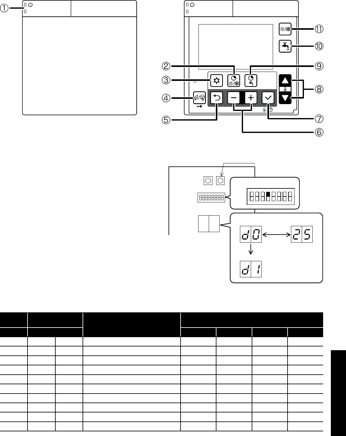
Section 10: Servicing Page 51
10.7 Monitor Display Function
The heat pump operating conditions, as listed in Table 10-3, can be
displayed and checked on either the remote controller or Terminal
PCB.
Door open
Figure 10-1: Remote controller buttons
Display on Remote controller
1. Press
Return
n button for three seconds to enter monitor mode
and display the user level value of parameter group 01. A 2
digit code number of parameter group 01 (default value is 00)
will be displayed on the left of remote controller screen. The
corresponding parameter value will displayed on the right of the
screen (default value is ----. )
2. Press the
Up
or
Down
q buttons to change the code number
and then press the Set p button to display the parameter value.
Only code numbers from 00 to 09 can be displayed.
3. To return to normal display, press and hold the
Return
n button
for three seconds or simply do nothing and leave it for about ten
minutes.
Display on Terminal PCB display
• Set the DIP SW4 on the Terminal PCB to ‘ON’ (up) to display the
monitor number and monitor data alternately.
• Push the Pump SW. of the Terminal PCB to switch the display
number alternately.
• To return to normal display, set the DIP SW4 to ‘OFF’ (down).
Terminal PCB Pump SW.
ON
OFF
number
change number
Pump SW.
moniter data
alternately
DIP SW4 = ON
Figure 10-2: Display on Terminal PCB display
Table 10-3: Monitor display
Terminal
PCB Remote controller Function description Display and input value
Number Parameter Default Minimum Maximum Unit
d0 01 00 Circulating water return temperature - -20 100 1°C
d1 01 01 Compressor operating frequency - 0 200 1Hz
d2 01 02 Discharge temperature - -20 150 1°C
d3 01 03 Current consumption value - 0 9900 100W
d4 01 04 Fan control number of rotation - 0 1000 10rpm
d5 01 05 Defrost temperature - -20 100 1°C
d6 01 06 Outdoor air temperature - -20 100 1°C
d7 01 07 Water pump control number of rotation - 0 9900 100rpm
d8 01 08 Suction temperature - -20 100 1°C
d9 01 09 Circulating water flow temperature - -20 100 1°C
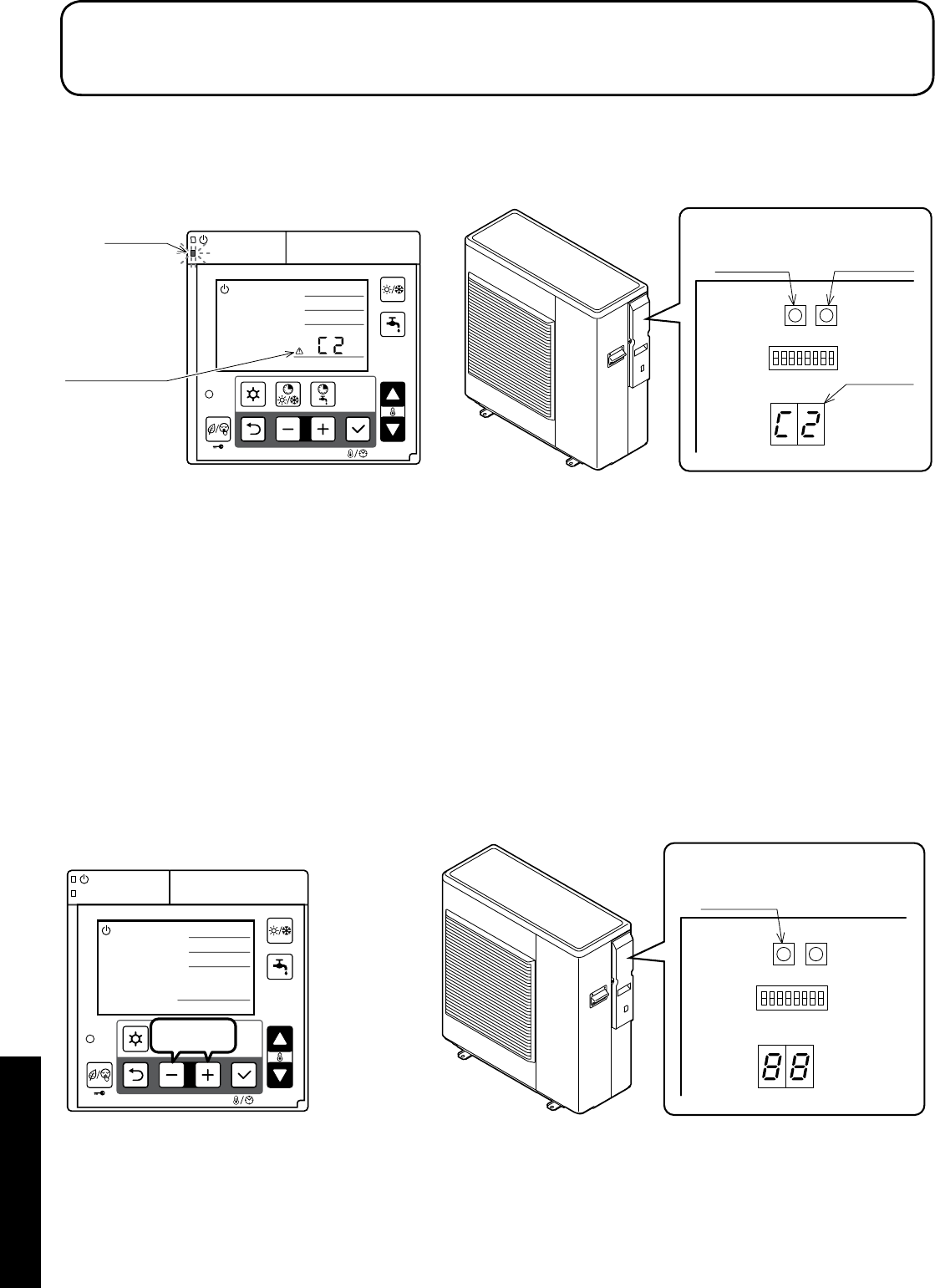
Section 11: Fault FindingPage 52
11.1 Error Code Display
In the event that a fault is detected, a red LED on the ON/OFF switch
of the remote controller will flash and a warning icon and error code
will be displayed on LCD screen and also on the Terminal PCB
display.
11 Fault Finding
Terminal PCB
Reset SW. Pump SW.
Display
Warning icon
and error code
Remote controller
LED(red)
Figure 11-1: Error code display
11.2 Error History Display
The previous 10 error codes can be displayed on Terminal PCB
display.
Procedure to display on Terminal PCB display:
1. Press Pump SW and Reset SW on Terminal PCB at the same
time for five seconds and the error history order and error code
will be displayed alternately. The first one is the latest error code.
2. Press Pump SW to go through the history order up to the 10th
error code and then go back to the latest error code.
3. When there is no error history, ‘--’ will be displayed.
If no operation is carried out for five minutes or both the Pump SW and
Reset SW are pressed together for five seconds, the display returns to
normal display.
Deletion of the error history:
During error code display, press Reset SW for ten seconds to delete
the error history.
Terminal PCB
Reset SW.
Remote controller
3seconds
Figure 11-2: Resetting error code display
11.3 Reset Error Code Display
Auto
Once it returns to normal condition, the error will automatically be
reset.
When the heat pump stops, it may not possible to reset automatically.
In this case, reset manually.
Manual
To reset, press
–
and
+
button at the same time for three seconds, or
press Reset SW on the Terminal PCB.
Refer to Figure 11-2.
It is possible to reset by turning the mains power supply switch OFF
→ ON, although this is not recommended.

Section 11: Fault Finding Page 53
11.4 Error Codes
Error
code Method of check Troubleshooting Figure/
table
Error
reset
- -
Power supply Check the power supply Confirm the power supply -
-
Fuse CF1
HPID6: 250V 15A
HPID10: 250V 25A
HPID16: 250V 30A
Check the electric continuity of Fuse CF1
by tester
If CF1 is blown, Main PCB should be
replaced
Figure
11-3
Fuse CF3
(250V 3A)
Check the electric continuity of Fuse CF3
by tester
If CF3 is blown, Main PCB should be
replaced
Fuse CF4
HPID6: 250V 3A
HPID10: 250V 3A
Check the electric continuity of
Fuse CF4 by tester
If CF4 is blown, Main PCB should be
replaced
Main PCB Other than described above Main PCB should be replaced -
A0 DC voltage error
Fan motor
Operate without lead wire for Fan motor
Check the electric continuity of Fuse by
tester
If the same error code appears again,
Main PCB or Pump should be replaced
If other error codes appear, Fan motor
should be replaced
-
Power
OFF
Fuse CF6
HPID16: 250V 3A If CF6 is blown,it should be replaced
Figure
11-4
Fuse CF7
HPID10: 250V 3A
HPID16: 250V 3A
If CF7 is blown,it should be replaced
Pump Operate without lead wire for
Pump
If the same error code appears again,
Main PCB or Fan motor should be
replaced
If other error codes appear, Pump should
be replaced
-
Reactor Check the resistance by tester
(0.1Ω at 20°C)
If the reactor is faulty, is should be
replaced. -
Main PCB Check the voltage of Fan motor by tester
Check the voltage of Pump by tester
If the voltage is abnormal, PCB (Main
should be replaced
Figure
11-4,
11-6
Power supply Check the power supply Confirm the power supply -
A1 Discharge
temperature error
Sensor, Temp.
Discharge Check the resistance by tester If the sensor is faulty, it should be
replaced
Figure
11-13
Auto
Gas leakage Check the service valve and refrigerant
circuit (pipe)
Collect refrigerant once, then recharge
with prescribed mass -
A2
Protective action
against excess
Current DC
current detection
Unreasonable
operation under/
overload
Check the place of installation (blockage
of air inlet & outlet)
Check the excess gas
Ensure the installation position to avoid
blockage of air inlet & outlet
- Manual
If excess gas is observed, collect all
refrigerant once, then recharge with
prescribed mass
Drop of power
voltage
Check the power voltage
(230V)
Confirm the power supply voltage
(230V)
Main PCB Operate without the junction connector of
Compressor lead wire
If the same error code appears again,
Main PCB should be replaced
Momentary stop
of power
(In case of
lightning)
- Restart operation
Compressor Other than described above Compressor should be replaced
A3 CT disconnection Main PCB - Main PCB should be replaced -
Manual
A4
Protective action
against excess
Current AC current
detection
Unreasonable
operation under/
overload
Check the place of installation (blockage
of air inlet & outlet)
Check the excess gas
Ensure the installation position to
avoid blockage of air inlet & outlet
-
If excess gas is observed, collect all
refrigerant once, then recharge with
prescribed mass
Drop of power
voltage
Check the power voltage
(230V)
Confirm the power supply voltage
(230V)
Momentary stop
of power (In case
of lightning)
- Restart operation

Section 11: Fault FindingPage 54
Error
code Method of check Troubleshooting Figure/
table
Error
reset
A5
Abnormal
revolution of
compressor
Unreasonable
operation under/
overload
Check the place of installation (blockage
of air inlet & outlet )
Check the excess gas
Ensure the installation position to avoid
blockage of air inlet & outlet
-
Manual
If excess gas is observed, collect all
refrigerant once, then recharge with
prescribed mass
Drop of power
voltage
Check the power voltage
(230V)
Confirm the power supply voltage
(230V)
Fuse CF6
HPID6: 250V 15A
HPID10 : 250V
25A
Check the electric continuity
Fuse CF6 by tester
If CF6 is blown, Main PCB should be
replaced
Figure
11-5
Clogged the water
Pump and/or
water circuit
Check the Pump and water circuit Remove the blockage, then restart
operation
Drop of power
voltage
Check the power voltage
(230V) during operation
Confirm the power supply voltage
(230V)
Momentary stop
of power
(In case of
lightning)
- Restart operation
Compressor or
Main PCB Other than described above Compressor should be replaced
A6
Suction
temperature
sensor error
Sensor, Temp.
Suction Check the resistance by tester If the sensor is faulty, it should be
replaced
Figure
11-14
Auto
A7 Defrost tem
sensor error
Sensor, Temp.
Defrost Check the resistance by tester If the sensor is faulty, it should be
replaced
Figure
11-14
A8 Discharge temp.
sensor error
Sensor, Temp.
Discharge
Check the resistance by tester
(*1)
If the sensor is faulty, it should be
replaced
Figure
11-13
C1
Upper fan motor
error
(HPID16)
Fuse CF7
(250V T3.15A)
Check the electric continuity
Fuse CF7 by tester
If CF7 is blown, Fan motor and CF7
should be replaced
If CF7 is not blown, check the voltage of
Fan motor
If the voltage is normal, Fan motor should
be replaced
If the voltage is abnormal, Main PCB
should be replaced
Figure
11-4 Auto
Fan motor (*2)
Main PCB
C2 Outdoor temp.
sensor error
Sensor, Temp.
Outdoor Check the resistance by tester If the sensor is faulty, it should be
replaced
Figure
11-12 Auto
C3
Lower Fan motor
error
(HPID16)
Fan motor error
(HPID6 and
HPID10)
Fuse CF6
(HPID16: 250V
T3.15A)
Check the electric continuity of Fuse CF6
by tester If CF6 is blown, it should be replaced
Figure
11-4
Manual
Fuse CF7
(HPID10: 250V
T3.15A)
Check the electric continuity of Fuse CF7
by tester If CF7 is blown, it should be replaced
Fan motor
Check the voltage of Fan motor by tester
If the voltage is normal, Fan motor should
be replaced
If the voltage is normal, Main PCB should
be replaced
Main PCB
C4
Rise of
temperature
(above 110°C) of
Main PCB
Mis-installation Check the place of installation (blockage
of air inlet & outlet)
Ensure the installation position to avoid
blockage of air inlet & outlet
-
Sensor, Temp.
Main PCB - Main PCB should be replaced
C5 Main PCB sensor
error
Sensor, Temp.
Main PCB - Main PCB should be replaced - Auto
C6 Main PCB error Main PCB - Main PCB should be replaced - Power
OFF
C7 Controller PCB
serial error
Mis wiring or rare
contact [Main
PCB - Controller
PCB connecting
cable]
Check the wiring connection and rare
contact
After correcting mis wiring, restart
operation
- Auto
Controller PCB Other than described above Controller PCB should be replaced
Main PCB Other than described above Main PCB should be replaced
Earth wire - Check if earth wire is properly installed
(*1) In case of detecting open circuit of the discharge temperature sensor, error display appears 10 minutes after start operating.
In case of detecting short circuit of the discharge temperature sensor, error display appears immediately.
(*2) When checking fan motor and/or pump, turn OFF the power supply completely and check at their terminal or connector.

Section 11: Fault Finding Page 55
Error
code Method of check Troubleshooting Figure/
table
Error
reset
C8 Main PCB error Main PCB
Turn off the power supply, wait for about
3 minutes, then power up again If the same error code appears,
Main PCB should be replaced -Power
OFF
Check loose cable connections and
contacts of reactor
E4 Outgoing water
temp. sensor error
Sensor, Temp.
Outgoing water Check the resistance by tester If the sensor is faulty, it should be
replaced
Figure
11-15
Auto
E5 Return water
temp. sensor error
Sensor, Temp.
Return water Check the resistance by tester If the sensor is faulty, it should be
replaced
FU
High pressure
switch is operating
(HPID16)
Outside air
recirculation
Check temperature difference of
Outgoing/Return water (see Monitor
display function)
Large difference means flow rate is too
low
Make sure the position doesn’t block the
air inlet and outlet
-
Manual
Clogged water
circuit
Remove the blockage, then restart
operation
P1 Pump error
Pump (*2)
Check the voltage of Pump
If the voltage is normal, Pump should be
replaced
If the voltage is abnormal, Main PCB
should be replaced
Figure
11-6
Main PCB
Clogged the water
Pump and/or
water circuit
Check the pump and water circuit Remove the blockage, then restart
operation -
P3
High pressure
switch error
(HPID16)
High pressure
switch
Check loose cable connections and
contacts
If the same error code appears, high
pressure switch should be replaced -Power
OFF
U1
Compressor
overheat
protection relay
operation
(HPID16)
Compressor
overheat
protection relay
Check the resistance by tester If the compressor overheat protection
relay is blown, it should be replaced
Figure
11-10
Manual
Gas leakage Check the service valve and refrigerant
circuit (pipe)
Correct refrigerant once, then recharge
with prescribed mass -
Water not getting warm
Fuse CF2
0639U : 250V T3.15A
1039U : 250V T3.15A
1639U : 250V T5A
Check the electric continuity of Fuse CF1
by tester
If CF2 is blown,it should be replaced and
check the resistance of 4way valve and
the resistance of Defrost heater by tester
Figure
11-9
-
4way valve Check the resistance of 4way valve by
tester
If 4way valve is blown,it should be
replaced
Figure
11-7
Defrost heater Check the resistance of Defrost heater
by tester
If Defrost heater is blown,it should be
replaced
Figure
11-8
Short cycle
(insufficient air
circulation)
Check the blockage of air inlet & outlet Ensure the installation position to avoid
blockage of air inlet & outlet -
Sensor,Temp.
Outgoing water
and Return water
Check the resistance by tester If any of these sensors is faulty, it should
be replaced
Figure
11-15
Gas leakage Check the service valve and refrigerant
circuit (pipe)
After fixing the leakage point,collect
the refrigerant once,then recharge with
prescribed mass
-
Clogged water
circuit
Check temperature difference of
Outgoing/Return water (see Monitor
display function)
Large difference means flow rate is too
low
Remove the blockage,then restart
operation -

Section 11: Fault FindingPage 56
11.5 Table of Controller PCB and Terminal PCB Alarms
Error
code Method of check Troubleshooting Figure/
table
Error
reset
L0 EEPROM error
PCB(Controller)
and
PCB(EEPROM)
-PCB(Controller) and PCB(EEPROM)
should be replaced -Power
OFF
L1 DHW temperature
sensor error
Sensor,
temperature
DHW tank
Check the resistance by tester If the sensor is faulty, it should be
replaced
Figure
11-14
Auto
L2
Outdoor
temperature
sensor error
Sensor,
temperature
outdoor
Check the resistance by tester If the sensor is faulty, it should be
replaced
Figure
11-16
L3
Thermal store
temperature
sensor error
Sensor,
temperature
thermal store
Check the resistance by tester If the sensor is faulty, it should be
replaced
Figure
11-14
L4
Mix water
temperature
sensor error
Sensor,
temperature
Mix water
Check the resistance by tester If the sensor is faulty, it should be
replaced
Figure
11-14
L5 Humidity sensor
error Sensor, Humidity Check the resistance by tester If the sensor is faulty, it should be
replaced
Figure
11-11
740
Remote controller
communication
error
Incorrect remote
controller wiring or
DIP SW setting
Check loose cable connections and
contacts
Check DIP SW setting After having corrected the wiring and DIP
SW setting, restart operation
-
Loose interface
connection cable
or contacts
Rear side of remote controller
Remote controller Other than described above Remote controller should be replaced
Controller PCB Other than described above Controller PCB should be replaced
E8
Remote controller
communication
error
Incorrect remote
controller wiring
Loose interface
connection cable
or contacts
Check loose cable connections and
contacts
After having corrected the wiring, restart
operation -
Controller PCB Other than described above Controller PCB should be replaced
F5
Main PCB
communication
error
Incorrect main
PCB wiring
Loose interface
connection cable
or contacts
Check loose cable connections and
contacts
After having corrected the wiring, restart
operation
-
Main PCB Other than described above Main PCB should be replaced
Controller PCB Other than described above Controller PCB should be replaced
Terminal PCB cannot be
operated
Terminal PCB does not
display anything
Lead wire of
Terminal PCB
Check lead wires are connected to the
connectors properly
Connect the connectors to both Terminal
PCB and Controller PCB steadily
- -
Ensure that there is no disconnection for
the lead wires Lead wires should be replaced
Terminal PCB Other than described above Terminal PCB should be replaced
Controller PCB Other than described above Controller PCB should be replaced
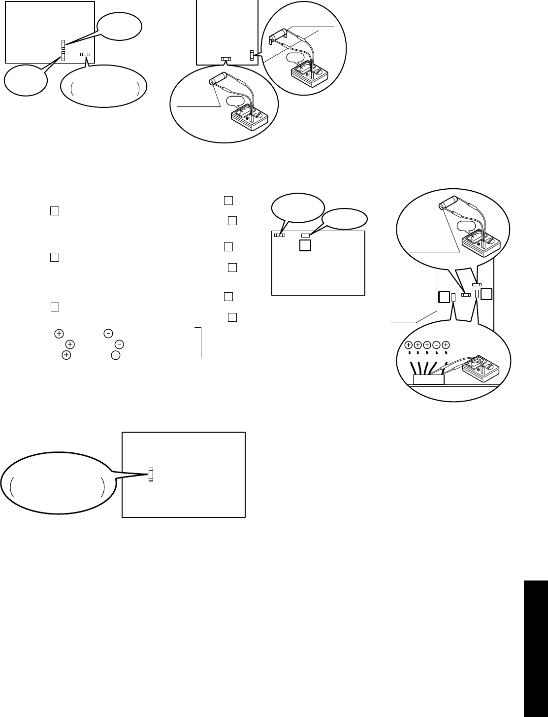
Section 11: Fault Finding Page 57
Figure 11-3: Continuity of current Fuse on the Main PCB
Figure 11-4: Voltage of Fan motor on the Main PCB
Figure 11-5: Continuity of current Fuse on the Main PCB
Main
PCB
Fuse CF1
(250V T30A)
0Ω
Fuse CF3
(250V 3A) 0Ω
Fuse CF4
(250V 3A)
Main
PCB
Fuse CF3
(250V 3A)
Fuse CF1
HPID6 : 250V 15A
HPID10 : 250V 25A
[HPID16][HPID6 and HPID10]
14 11
BL Y W B R
LOWER:
Fuse CF6
UPPER:
Fuse CF7
(250V T3.15A)
0Ω
Fan motor
Main
PCB
18
Fan motor
Main
PCB
Fuse CF7
(250V T3.15A)
Measure voltage between the connector pins of connector 11.
Connector 11 shall be checked during heating operation.
Measure voltage as follows without taking off the connector 11.
Measure voltage between the connector pins of connector
18
.
Connector
18
shall be checked during heating operation.
Measure voltage as follows without taking off the connector
18
.
Measure voltage between the connector pins of connector
14
.
Connector
14
shall be checked during heating operation.
Measure voltage as follows without taking off the connector
14
.
Between red and black , approx. DC200~370V
Between yellow and black , approx. DC3~7V
Between white and black , approx. DC15V
Main PCB is normal
LOWER Fan motor (HPID16)
Fan motor (HPID6 and HPID10)
UPPER Fan motor (HPID16)
[HPID16][HPID6 and HPID10]
Main
PCB
Fuse CF6
HPID6: 250V 15A
HPID10: 250V 25A
11.6 Error Codes and PCB Alarm Figures and Tables
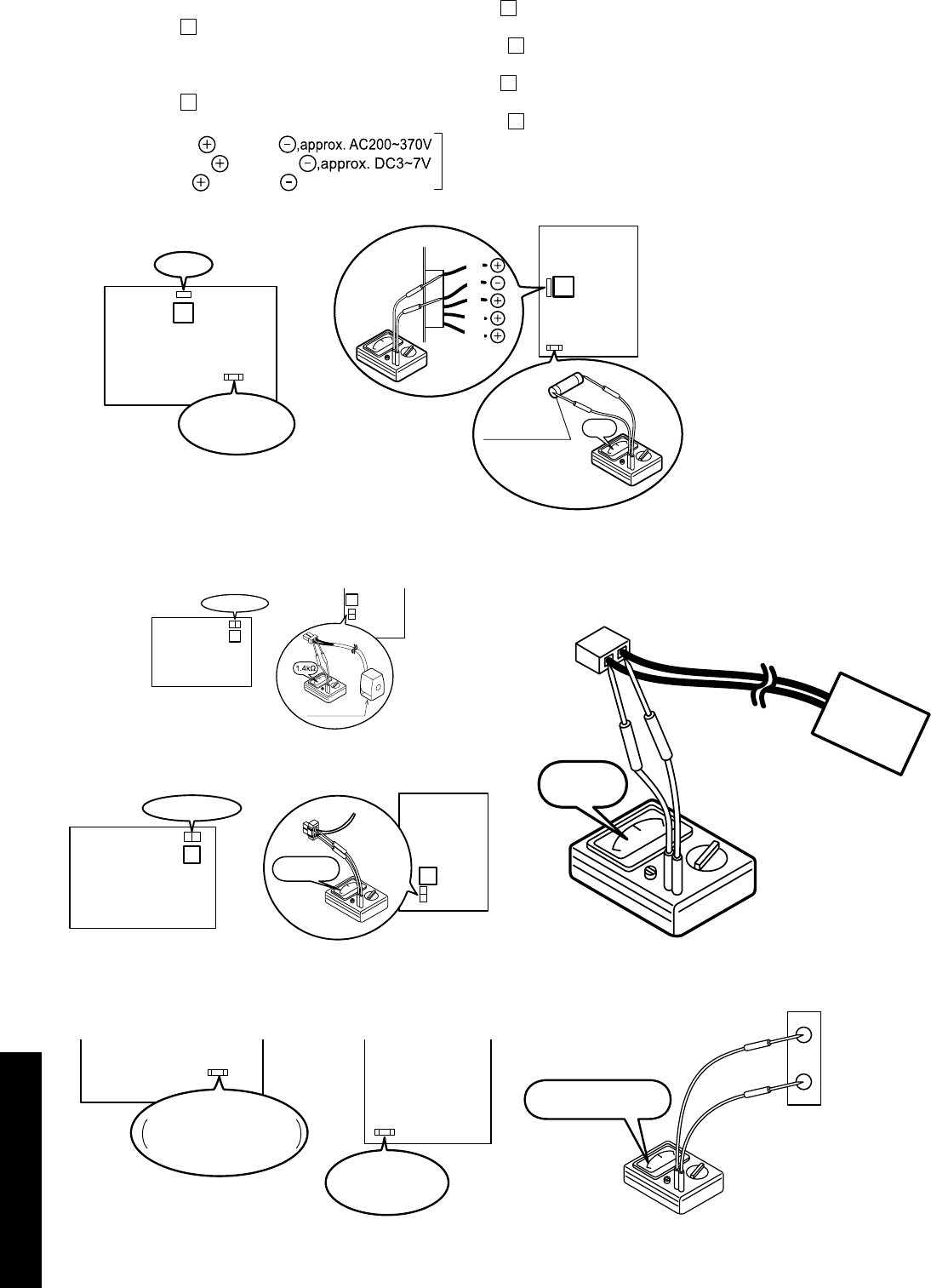
Section 11: Fault FindingPage 58
Figure 11-6: Voltage of pump on the Main PCB
Figure 11-7: Resistance of the 4way valve coil
Figure 11-8: Resistance of the defrost heater
Figure 11-9: Continuity of current fuse on the Main PCB
Figure 11-10: Resistance of the compressor overheat protection
relay
Figure 11-11: Voltage of humidity sensor
17
Pump
Fuse CF2
(250V T3.15A)
Main
PCB
Between white and black
Between brown and black
Between red and black
,approx. DC15V
Main PCB is normal
W
B
R
BR
BL
13
Fuse CF2
(250V T5A) 0Ω
Pump
Main
PCB
[HPID16]
[HPID6 and HPID10]
Measure voltage between the connector pins of connector
17
.
Connector
17
shall be checked during heating operation.
Measure voltage as follows without taking off the connector
17
.
Measure voltage between the connector pins of connector
13
.
Connector
13
shall be checked during heating operation.
Measure voltage as follows without taking off the connector
13
.
Pump (HPID6 and HPID10)
Pump (HPID16)
8
4-way valve coil
Main
(PCB
10
4way valve coil
Main
PCB
Take off the connector and check the resistance 4way valve coil.
[HPID16]
[HPID6 and HPID10]
9
260~300Ω Main
PCB
11
Main
PCB
Defrost heater
[HPID16]
[HPID6 and HPID10]
PCB
(Main)
PCB
(Main)
Fuse CF2
0639U : 250V T3.15A
1039U : 250V T3.15A
Fuse CF2
(250V T5A)
[1639U][0639U,1039U]
0Ω
OHR
0.147~9.80V
17
18
Humidity
Sensor
COM

Section 11: Fault Finding Page 59
Table 11-12: Sensor, temperature outdoor (heat pump)
Temperature (°C) Resistance (kΩ)
0 31
5 24
10 19
15 15
20 12
25 10
30 8.2
35 6.7
40 5.5
45 4.6
50 3.8
55 3.2
Table 11-13: Sensor, temperature discharge (heat pump)
Temperature (°C) Resistance (kΩ)
10 100
20 64
35 33
40 27
50 18
80 6.4
Table 11-14: Sensor, temperature defrost/suction (heat pump)
Sensor temperature DHW tank/thermal store/mix water (Terminal
PCB)
Temperature (°C) Resistance (kΩ)
0 29
5 23
10 19
15 15
20 12
25 10
30 8.3
35 6.9
40 5.7
45 4.8
50 4.1
55 3.4
Table 11-15: Sensor, temperature flow and return circulating water
(heat pump)
Temperature (°C) Resistance (kΩ)
0 25
10 16
20 10
30 7.0
40 4.9
50 3.5
60 2.5
Table 11-16: Sensor, temperature outdoor (Terminal PCB)
Temperature (°C) Resistance (kΩ)
-20 107
-15 79
-10 59
-5 44
0 34
5 26
10 20
15 16
20 13
25 10
30 8.0
35 6.5
40 5.3
45 4.3
50 3.6
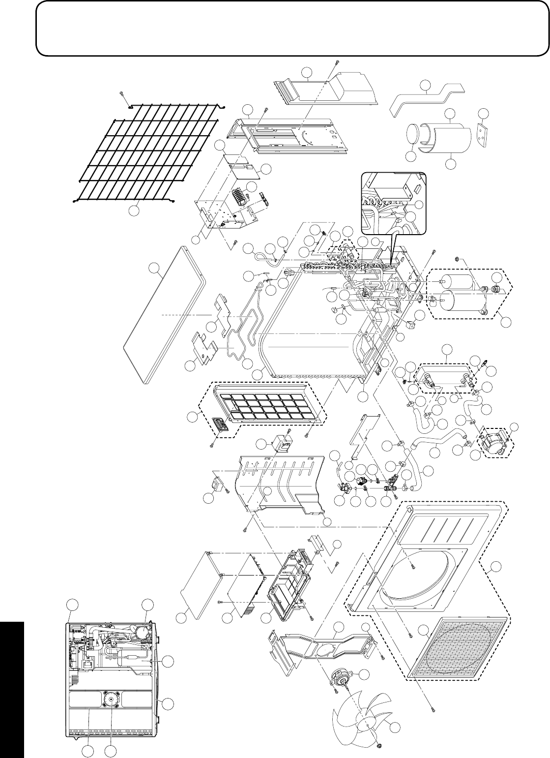
Section 12: Spare PartsPage 60
12 Spare Parts
C
A
B
A
B
D
E
F
F
C
D
G
G
E
6
7
1
2
8
68
28
67 25
72
4
62
45
15
39
60
60
11
60
58
58
66
55
42
56
41 29
20
21
36 34
35
37
33
12
3
73
80
27
26
16
46
22
22 44
54
51
14
38
9
69
13
70
71
24
57
62
5
53
54
60
47 60
61
60
48
24
17
57
65
61
49
50
18
18
5
8
7
11 20
12.1 Exploded Diagram - HPID6

Section 12: Spare Parts Page 61
12.2 Spare Parts List - HPID6
Item Description Product code
1 Outlet grille HPID927368
2 Front panel assembly HPID885766
3 Right side panel HPID883774
4 Left side panel assembly HPID883741
5 Top panel HPID884558
6 Propeller fan HPID922330
7 Motor HPID937022
8 Bracket (motor) HPID937023
9 Sensor (temperature outdoor) HPID883780
11 Bottom panel assembly (without heater) HPID883759
12 Wiring lid assembly HPID937262
13 Condenser assembly HPID883743
14 Coil (expansion valve) HPID937196
15 Expansion valve HPID922928
16 Sensor (temperature defrost) HPID937014
17 Heat exchanger assembly HPID883744
18 Pump assembly HPID885394
20 Compressor HPID937199
21 Vibration proof rubber HPID883782
22 Sensor (temperature discharge/suction) HPID937013
24 Sensor (temperature water) HPID937193
25 Reactor HPID927200
26 Terminal block HPID885263
27 Terminal PCB HPID885254
28 Main PCB HPID885392
29 Rubber hose (for relief valve) HPID883784
33 Sound proof material 1 HPID883791
34 Sound proof material 2 HPID883792
35 Sound proof material 3 HPID883793
36 Sound proof material 4 HPID883794
37 Sound proof material 5 HPID883795
38 Outdoor themistor holder HPID937016
39 Coil - 4-way valve HPID883796
41 Relief valve HPID883798
42 Air purge valve HPID885266
44 4-way valve HPID927359
45 Circulating water flow port assembly HPID884560
46 Circulating water return port assembly HPID883778
47 Rubber hose 1 HPID883786
48 Rubber hose 8 HPID884561
49 Rubber hose 3 HPID885396
50 Rubber hose 4 HPID885397
51 Rubber hose 6 HPID883790
53 O-ring (P3) HPID807209
54 O-ring (P4) HPID807207
55 O-ring (P12.5) HPID808972
56 O-ring (P14) HPID910164
Item Description Product code
57 Quick fastener (for sensor temperature
water) HPID883848
58 Quick fastener (12.7) HPID790706
60 Hose band A HPID937221
61 Hose band B HPID927535
62 Hose band C HPID934914
65 Drain plug HPID885519
66 Circulating water connection coupling HPID885395
67 Case of PCB HPID883847
68 Case of PCB (cover) HPID885393
69 Defrost heater HPID884211
70 Defrost heater holder 1 HPID884212
71 Defrost heater holder 2 HPID884213
72 Power transformer HPID885264
73 Controller PCB HPID885765
80 Fin guard HPID885782
Section 12: Spare PartsPage 62
I
A
MJ
H
E
C
C
D
GF
B
HI
J
B
3
1
6
7
11
51
25
33
30
33
17
33
27
54
58
50
60
56
51
24
55
29
33
59
53 47
57
55
59
57
60
50
17
56
23
52
48
32
49
26
18
20
A
4
16
16
13
12
15
19
14
5
10
64
34
35 41
46
44
58
54
28
31
42
M
38
39
40
36
9
8
43
D
E
G
22
21
2
37
61
62
63
65
66
F
L
L
45 70
N
K
K
N
22
34
11
4
10
7
6
12.3 Exploded Diagram - HPID10

Section 12: Spare Parts Page 63
12.4 Spare Parts List - HPID10
Item Description Product code
1 Outlet grille HPID938106
2 Front panel assembly (left) HPID885767
3 Front panel assembly (right) HPID885768
4 Top panel assembly HPID885504
5 Propeller fan HPID934945
6 Motor HPID885510
7 Bracket (motor) HPID934947
8 Wiring lid HPID885507
9 Back panel assembly HPID885769
10 Bottom panel assembly (without heater) HPID885506
11 Condenser assembly HPID883634
12 Expansion valve HPID885511
13 Coil (expansion valve) HPID884119
14 4-way valve HPID938113
15 Coil (4-way valve) HPID883796
16 Sensor (temperature discharge and suction) HPID937013
17 Sensor (temperature circulating water) HPID885265
18 Sensor (temperature defrost) HPID937014
19 Sensor (temperature outdoor) HPID883780
20 Outdoor thermistor holder HPID937016
21 Heat exchanger assembly HPID885509
22 Pump assembly HPID885512
23 Circulating water pipe assembly HPID885513
24 Circulating water return port HPID885514
25 Bypass pipe assembly HPID885515
26 Drain plug HPID885519
27 Hose coupling 1 assembly (pump inlet) HPID885516
28 Hose coupling 2 assembly (pump outlet) HPID885271
29 Hose coupling 3 (heat exchanger) HPID885272
30 Rubber hose (pump inlet water) HPID885273
31 Rubber hose (pump outlet water) HPID885517
32 Rubber hose (for relief valve) HPID885520
33 Hose band HPID937221
34 Compressor HPID934944
35 Vibration proof rubber HPID934959
36 Reactor HPID885259
37 Terminal block HPID885263
38 Case of PCB (cover) HPID885393
39 Main PCB HPID885501
40 Case of PCB HPID883847
41 Sound proof material 1 HPID883882
42 Sound proof material 2 HPID883883
43 Sound proof material 3 HPID883884
44 Sound proof material 4 HPID883885
45 Sound proof material 5 HPID884582
46 Sound proof material 6 HPID885518
47 Relief valve HPID883798
Item Description Product code
48 Air purge valve HPID885266
49 O-ring (P3) HPID807209
50 O-ring (P4) HPID807207
51 O-ring (P6) HPID807205
52 O-ring (P12.5) HPID808972
53 O-ring (P14) HPID910164
54 O-ring (P16) HPID807213
55 O-ring (P22) HPID922856
56 Quick fastener HPID761569
57 Quick fastener (12.7) HPID790706
58 Quick fastener (16A) HPID963516
59 Quick fastener (16B) HPID884148
60 Quick fastener (sensor temperature water) HPID883848
61 Terminal PCB HPID885254
62 Controller PCB HPID885765
63 Power transformer HPID885264
64 Defrost heater HPID885508
65 Defrost heater holder 1 HPID884163
66 Defrost heater holder 2 HPID884132
70 Fin guard HPID885781
Section 12: Spare PartsPage 64
3
1
52
53
54
55
13
70
71
21
61
23
4
7
11
10
10
12
62
60
23
8
22
16
26
35
51
32
48
31
43
49
33
33
47
20
36
27
64
63
64
14
17 29
37
45
41
45
38
30
46
20
36
34
28
34
39
50
45
42 45
40
51
35
50
47
6
5
58
59
57
19
9
9
56
7
23
10
10
11 4
8
9 13
31
14
57
59
32
29
28
16
2
2
15
18
18
O
I
B
B
A
P
L
C
G
P
F
A
DE
F
N
C
O
I
J
H
M
J
E
M
D
H
25
24
G
K
N
K
L
R
R
12.5 Exploded Diagram - HPID16

Section 12: Spare Parts Page 65
12.6 Spare Parts List - HPID16
Item Description Product code
1 Front panel assembly (left) HPID885255
2 Outlet grille HPID938106
3 Front panel assembly (right) HPID885770
4 Top panel assembly HPID884552
5 Back panel assembly (right) HPID885257
6 Wiring lid HPID884129
7 Back panel (left) HPID884126
8 Bottom panel assembly (without heater) HPID885258
9 Reactor HPID885259
10 Motor HPID885260
11 Bracket (motor) HPID885261
12 Propeller fan HPID938112
13 Main PCB assembly HPID885252
14 Terminal block HPID885263
15 Coil (4-way valve) HPID883796
16 Coil (expansion valve) HPID884119
17 Sensor (temperature defrost) HPID937014
18 Sensor (temperature discharge and suction) HPID884139
19 Sensor (temperature outdoor) HPID884140
20 Sensor (temperature water) HPID885265
21 Compressor HPID884116
22 Vibration proof rubber HPID884135
23 Condenser assembly HPID884136
24 4-way valve HPID884117
25 High pressure switch HPID884120
26 Expansion valve HPID884118
27 Circulating water pipe assembly HPID885267
28 Pump assembly HPID885268
29 Heat exchanger assembly HPID885262
30 Drain plug HPID885519
31 Relief valve HPID883798
32 Air purge valve HPID885266
33 Quick fastener (12.7) HPID790706
34 Quick fastener (16A) HPID963516
35 Quick fastener (16B) HPID884148
36 Quick fastener (sensor temperature water) HPID883848
38 Circulating water return port HPID885269
38 Hose coupling 1 assembly (pump input) HPID885270
39 Hose coupling 2 (pump outlet) HPID885271
40 Hose coupling 3 (heat exchanger) HPID885272
41 Rubber hose (pump input) HPID885273
42 Rubber hose (pump outlet) HPID885274
43 Rubber hose (relief valve) HPID934970
45 Hose band HPID937221
46 O-ring (P3) HPID807209
47 O-ring (P4) HPID807207
48 O-ring (P12.5) HPID808972
Item Description Product code
49 O-ring (P14) HPID910164
50 O-ring (P16) HPID807213
51 O-ring (P22) HPID922856
52 Sound proof material 1 HPID884142
53 Sound proof material 2 HPID884143
54 Sound proof material 3 HPID885276
55 Sound proof material 4 HPID885277
56 Drain elbow HPID881618
57 Controller PCB HPID885765
58 Terminal PCB HPID885254
59 Power transformer HPID885264
60 Defrost heater HPID884130
61 Defrost heater holder 1 HPID884131
62 Defrost heater holder 2 HPID884132
63 Rubber hose HPID885275
64 Hose band HPID934914
70 Fin guard - back HPID885779
71 Fin guard - side HPID885780

Section 13: EC Declaration of ConformityPage 66
This declaration is made under the sole responsibility of the following Manufacturer.
The Manufacturer declares that the following Products conform to the requirements of EU Directives, Regulations and Harmonized Standards as
below stated.
The Technical Construction Files are retained at the following Manufacturer’s location.
Product: Air to Water Heat Pump
Model: GRANT AERONA³ HPID6
GRANT AERONA³ HPID10
GRANT AERONA³ HPID16
Low Voltage Directive:
2014/35/EU
Machinery Directive:
2006/42/EC
EN 60335-2-40 : 2003, +All: 2004, +Al2: 2005, +Al: 2006, +A2: 2009, +Al3: 2012
EN 60335-1 : 2012, +All: 2014
EN 62233 : 2008
EMC Directive:
2014/30/EU
EN 61000-6-1 : 2007
EN 61000-6-3 : 2007, +A1:2001
Ecodesign Directive:
2009/125/EC [Space heaters and combination heaters: 811/2013; 813/2013]
EN 14511-3 : 2013
EN 14825 : 2013
EN 12102 : 2013
EN 16147 : 2011
BS EN ISO 3743-1 : 2010
RoHS Directive:
2011/65/EU
EN 50581 : 2012
Place of issue: United Kingdom
Date of issue: 22nd March 2016
Authorised Signatory:
Neil Sawers - Technical Manager
13 EC Declaration of Conformity

Section 14: Health and Safety Information Page 67
14.1 General
Under the Consumer Protection Act 1987 and Section 6 of the Health
and Safety at Work Act 1974, we are required to provide information
on substances hazardous to health (COSHH Regulations 1988).
Adhesives, sealants and paints used in the manufacture of the
product are cured and present no known hazards when used in the
manner for which they are intended.
Isolate the heat pump from the electricity supply before remov-
ing any covers.
!WARNING
14 Health and Safety Information
14.2 Refrigerant (R410A)
The refrigerant is hermetically sealed within the heat pump.
Work involving the refrigerant must only be performed by a qualified
F-Gas Engineer or an authorised dealer with a refrigerant handling
certificate.
Under no circumstances should the refrigerant be vented or
otherwise released to the atmosphere.
14.2.1 First Aid Measures
Inhalation
In low concentrations may cause narcotic effects. Symptoms may
include dizziness, headache, nausea and loss of co-ordination.
In high concentrations may cause asphyxiation. Symptoms may
include loss of mobility/consciousness. Victim may not be aware of
asphyxiation.
Remove victim to uncontaminated area wearing self contained
breathing apparatus. Keep victim warm and rested. Seek urgent
medical advice.
Apply artificial respiration if breathing stopped.
Skin/eye contact
In case of frostbite spray with water for at least 15 minutes. Apply a
sterile dressing.
Immediately flush eyes thoroughly with water for at least 15 minutes.
Remove contaminated clothing. Drench affected area with water for
at least 15 minutes.
Obtain medical assistance
Ingestion
Ingestion is not considered a potential route of exposure.
General
Grant UK air source heat pumps incorporate components
manufactured from a variety of different materials. However, most of
these materials cannot be recycled as they are contaminated by the
refrigerant and oil used in the heat pump.
Disassembly
This product may only be disassembled by a suitably qualified
(F-gas) refrigeration engineer.
Under no circumstances should the refrigerant be released into the
atmosphere.
15 Disposal and Recycling
Recycling
In order for the heat pump to be recycled or disposed of it must be
taken to a suitably licensed waste facility. You will need to contact a
qualified refrigeration engineer to do this for you.
Disposal
The refrigerant will be removed and returned to the refrigerant
manufacturer for recycling or disposal.
The complete heat pump unit, including the compressor and the oil
contained within it, must be disposed of at a licensed waste facility,
as it still remains contaminated by the refrigerant.

Section 15: GuaranteePage 68
You are now the proud owner of an Air Source Heat Pump from Grant
Engineering (UK) Limited which has been designed to give years of
reliable, trouble free, operation.
Grant Engineering (UK) Limited guarantees the manufacture of the
heat pump including all electrical and mechanical components for a
period of twelve months from the date of installation4, provided that
the air source heat pump has been installed in full accordance with
the installation and servicing instructions issued.
This will be extended to a total period of two years if the air source
heat pump is registered with Grant Engineering (UK) Limited within
thirty days of installation4 and it is serviced at twelve monthly
intervals3. See main Terms and Conditions below.
Registering the product with Grant Engineering (UK) Limited
Please register your air source heat pump with Grant Engineering
(UK) Limited within thirty days of installation. To do so visit w ww.
grantuk.com and follow the links to the ‘Homeowners Zone’, where
you can register your boiler for a further twelve months guarantee
(giving two years from the date of installation). This does not affect
your statutory rights1.
If a fault or defect occurs within the manufacturer’s guarantee
period
If your air source heat pump should fail within the guarantee period,
you must contact Grant Engineering (UK) Limited, who will arrange
for the repair under the terms of the guarantee, providing that the
heat pump has been correctly installed, commissioned and serviced
(if the appliance has been installed for more than twelve months) by
a competent person and the fault is not due to tampering, system
water contamination, misuse, trapped air or the failure of any external
components not supplied by Grant Engineering (UK) Limited, e.g.
pipework, etc.
This two year guarantee only applies if the air source heat pump is
registered with Grant Engineering (UK) Limited within thirty days of
installation4 and is serviced after twelve months3.
In the first instance
Contact your installer or commissioning engineer to ensure that
the fault does not lie with the system components or any incorrect
setting of the system controls that falls outside of the manufacturer’s
guarantee otherwise a service charge could result. Grant Engineering
(UK) Limited will not be liable for any charges arising from this
process.
If a fault covered by the manufacturer’s guarantee is found
Ask your installer to contact Grant Engineering (UK) Limited Service
Department on +44 (0)1380 736920 who will arrange for a competent
service engineer to attend to the fault.
Remember - before you contact Grant Engineering (UK) Limited:
• Ensure the air source heat pump has been installed,
commissioned and serviced by a competent person in
accordance with the installation and servicing instructions.
• Ensure the problem is not being caused by the heating system or
its controls.
16 Guarantee
Free of charge repairs
During the two year guarantee period no charge for parts or
labour will be made, provided that the air source heat pump has
been installed and commissioned correctly in accordance with the
manufacturer’s installation and servicing instructions, it was registered
with Grant Engineering (UK) Limited within thirty days of installation4
and, for air source heat pumps over twelve months old, details of
annual service is available3.
The following documents must be made available to Grant
Engineering (UK) Limited on request:
• Proof of purchase
• Commissioning Report Form
• Service documents
• System Design Criteria
Chargeable repairs
A charge may be made (if necessary following testing of parts) if the
cause of the breakdown is due to any fault(s) caused by the plumbing
or heating system, e.g. contamination of parts due to system
contamination, sludge, scale, debris or trapped air. See ‘Extent of
manufacturer’s guarantee’ below.
Extent of manufacturer’s guarantee:
The manufacturer’s guarantee does not cover the following:
• If the air source heat pump has been installed for over two years.
• If the air source heat pump has not been installed,
commissioned, or serviced by a competent person in
accordance with the installation and servicing instructions.
• The serial number has been removed or made illegible.
• Fault(s) due to accidental damage, tampering, unauthorised
adjustment, neglect, misuse or operating the air source heat
pump contrary to the manufacturer’s installation and servicing
instructions.
• Damage due to external causes such as bad weather conditions
(flood, storms, lightning), fire, explosion, accident or theft.
• Fault(s) due to incorrectly sized expansion vessel(s), incorrect
vessel charge pressure or inadequate expansion on the system.
• Fault(s) caused by external electrics and external components
not supplied by Grant Engineering (UK) Limited.
• Air source heat pump servicing, de-scaling or flushing.
• Checking and replenishing system pressure.
• Electrical cables and plugs, external controls not supplied by
Grant Engineering (UK) Limited.
• Heating system components, such as radiators, pipes, fittings,
pumps and valves not supplied by Grant Engineering (UK)
Limited.
• Instances where the heat pump has been un-installed and re-
installed in another location.
• Use of spare parts not authorised by Grant Engineering (UK)
Limited.
• Consumable items including, but not limited to, antifreeze and
biocide inhibitor.

Section 15: Guarantee Page 69
Terms of manufacturer’s guarantee:
• The Company shall mean Grant Engineering (UK) Limited.
• The heat pump must be installed by a competent installer and in
full accordance with the relevant Codes of Practice, Regulations
and Legislation in force at the time of installation.
• The heat pump is guaranteed for two years from the date of
installation4, providing that after twelve months the annual
service has been completed3 and the heat pump registered with
the Company within thirty days of the installation date4. Any work
undertaken must be authorised by the Company and carried out
by a competent service engineer.
• The internal heat exchanger of the heat pump is also covered
by a two year parts and labour guarantee from the date of
installation4. This is subject to the following:
• The heat pump is operated correctly, in accordance with the
installation and servicing instructions.
• Proof is provided that the system has been flushed or
chemically cleaned where appropriate (refer to BS 7593)
and that the required quantity of a suitable corrosion
inhibitor added.
• Proof of annual servicing (including the checking of any
expansion vessels and pressure relief valves) must be
provided if and when requested by the Company.
IMPORTANT
Grant Engineering (UK) Limited strongly recommends that a
Grant MagOne in-line magnetic filter/s (or equivalent5) is fitted
in the heating system pipework. This should be installed and
regularly serviced in accordance with the filter manufacturer’s
instructions.
• This guarantee does not cover breakdowns caused by incorrect
installation, neglect, misuse, accident or failure to operate the
heat pump in accordance with the manufacturer’s installation and
servicing instructions.
• The heat pump is registered with the Company within thirty days
of installation. Failure to do so does not affect your statutory
rights1.
• The balance of the guarantee is transferable providing the
installation is serviced prior to the dwelling’s new owners taking
up residence. Grant Engineering (UK) Limited must be informed
of the new owner’s details.
• The Company will endeavour to provide prompt service in
the unlikely event of a problem occurring, but cannot be held
responsible for any consequences of delay however caused.
• This guarantee applies to Grant Engineering (UK) Limited
air source heat pumps purchased and installed on the UK
mainland, Isle of Wight, Channel Islands and Scottish Isles only2.
Provision of in-guarantee cover elsewhere in the UK is subject to
agreement with the Company.
• All claims under this guarantee must be made to the Company
prior to any work being undertaken. Invoices for call out/repair
work by any third party will not be accepted unless previously
authorised by the Company.
• Proof of purchase and date of installation, commissioning and
service documents must be provided on request.
• If a replacement heat pump is supplied under the guarantee (due
to a manufacturing fault) the product guarantee continues from
the installation date of the original heat pump, and not from the
installation date of the replacement4.
• The replacement of a heat pump under this guarantee does not
include any consequential costs.
Foot notes:
1. Your statutory rights entitle you to a one year guarantee period
only.
2. The UK mainland consists of England, Scotland and Wales only.
Please note that for the purposes of this definition, Northern
Ireland, Isle of Man and Scilly Isles are not considered part of the
UK mainland.
3. We recommend that your air source heat pump is serviced every
twelve months (even when the guarantee has expired) to prolong
the lifespan and ensure it is operating safely and efficiently.
4. The guarantee period will commence from the date of installation,
unless the installation date is more than six months from the date
of purchase, in which case the guarantee period will commence
six months from the date of purchase.
5. As measured by gauss. The MagOne magnetic filter has a Gauss
measurement of 12000.
Version 1.0

Appendix APage 70
Appendix A
ErP product fiche and energy label
While it is the manufacturer’s responsibility to issue their products with the required energy labels, it is the installer’s responsibility to issue a
‘combination’ product fiche and energy label to the end user/householder, i.e. when a heat pump and cylinder are installed together.
All ‘combination’ product fiches and energy labels can be downloaded from ww w.grantuk.com. Refer to the table below to ensure you are
issuing the correct product fiche and energy label.
Heat pump model Cylinder model Combination
Product fiche Energy label
HPID6
HPMONOA/IND200 HPID6 and HPMONOA/IND200 product fiche HPID6 and HPMONOA/IND200 energy label
HPMONO/IND125 HPID6 and HPMONO/IND125 product fiche HPID6 and HPMONO/IND125 energy label
HPMONO/IND150 HPID6 and HPMONO/IND150 product fiche HPID6 and HPMONO/IND150 energy label
HPMONO/IND170 HPID6 and HPMONO/IND170 product fiche HPID6 and HPMONO/IND170 energy label
HPMONO/IND200 HPID6 and HPMONO/IND200 product fiche HPID6 and HPMONO/IND200 energy label
HPMONO/IND250 HPID6 and HPMONO/IND250 product fiche HPID6 and HPMONO/IND250 energy label
HPMONO/IND300 HPID6 and HPMONO/IND300 product fiche HPID6 and HPMONO/IND300 energy label
HPMONO/IND400 HPID6 and HPMONO/IND400 product fiche HPID6 and HPMONO/IND400 energy label
HPDUO/IND170 HPID6 and HPDUO/IND170 product fiche HPID6 and HPDUO/IND170 energy label
HPDUO/IND200 HPID6 and HPDUO/IND200 product fiche HPID6 and HPDUO/IND200 energy label
HPDUO/IND250 HPID6 and HPDUO/IND250 product fiche HPID6 and HPDUO/IND250 energy label
HPDUO/IND300 HPID6 and HPDUO/IND300 product fiche HPID6 and HPDUO/IND300 energy label
HPDUO/IND400 HPID6 and HPDUO/IND400 product fiche HPID6 and HPDUO/IND400 energy label
HPID10
HPMONOA/IND200 HPID10 and HPMONOA/IND200 product fiche HPID10 and HPMONOA/IND200 energy label
HPMONO/IND125 HPID10 and HPMONO/IND125 product fiche HPID10 and HPMONO/IND125 energy label
HPMONO/IND150 HPID10 and HPMONO/IND150 product fiche HPID10 and HPMONO/IND150 energy label
HPMONO/IND170 HPID10 and HPMONO/IND170 product fiche HPID10 and HPMONO/IND170 energy label
HPMONO/IND200 HPID10 and HPMONO/IND200 product fiche HPID10 and HPMONO/IND200 energy label
HPMONO/IND250 HPID10 and HPMONO/IND250 product fiche HPID10 and HPMONO/IND250 energy label
HPMONO/IND300 HPID10 and HPMONO/IND300 product fiche HPID10 and HPMONO/IND300 energy label
HPMONO/IND400 HPID10 and HPMONO/IND400 product fiche HPID10 and HPMONO/IND400 energy label
HPDUO/IND170 HPID10 and HPDUO/IND170 product fiche HPID10 and HPDUO/IND170 energy label
HPDUO/IND200 HPID10 and HPDUO/IND200 product fiche HPID10 and HPDUO/IND200 energy label
HPDUO/IND250 HPID10 and HPDUO/IND250 product fiche HPID10 and HPDUO/IND250 energy label
HPDUO/IND300 HPID10 and HPDUO/IND300 product fiche HPID10 and HPDUO/IND300 energy label
HPDUO/IND400 HPID10 and HPDUO/IND400 product fiche HPID10 and HPDUO/IND400 energy label
HPID16
HPMONOA/IND200 HPID16 and HPMONOA/IND200 product fiche HPID16 and HPMONOA/IND200 energy label
HPMONO/IND125 HPID16 and HPMONO/IND125 product fiche HPID16 and HPMONO/IND125 energy label
HPMONO/IND150 HPID16 and HPMONO/IND150 product fiche HPID16 and HPMONO/IND150 energy label
HPMONO/IND170 HPID16 and HPMONO/IND170 product fiche HPID16 and HPMONO/IND170 energy label
HPMONO/IND200 HPID16 and HPMONO/IND200 product fiche HPID16 and HPMONO/IND200 energy label
HPMONO/IND250 HPID16 and HPMONO/IND250 product fiche HPID16 and HPMONO/IND250 energy label
HPMONO/IND300 HPID16 and HPMONO/IND300 product fiche HPID16 and HPMONO/IND300 energy label
HPMONO/IND400 HPID16 and HPMONO/IND400 product fiche HPID16 and HPMONO/IND400 energy label
HPDUO/IND170 HPID16 and HPDUO/IND170 product fiche HPID16 and HPDUO/IND170 energy label
HPDUO/IND200 HPID16 and HPDUO/IND200 product fiche HPID16 and HPDUO/IND200 energy label
HPDUO/IND250 HPID16 and HPDUO/IND250 product fiche HPID16 and HPDUO/IND250 energy label
HPDUO/IND300 HPID16 and HPDUO/IND300 product fiche HPID16 and HPDUO/IND300 energy label
HPDUO/IND400 HPID16 and HPDUO/IND400 product fiche HPID16 and HPDUO/IND400 energy label

Notes Page 71
Notes

GRANT ENGINEERING (UK) LIMITED
Hopton House, Hopton Industrial Estate, Devizes, Wiltshire, SN10 2EU
Tel: +44 (0)1380 736920 Fax: +44 (0)1380 736991
Email: info@grantuk.com www.grantuk.com
