Designjet T9x0, T15x0 EPrinter Series And T25x0, T3500 EMultifunction Service Manual HP E Printer Multifunction
User Manual: Pdf HP Designjet T9x0, T15x0 ePrinter Series and T25x0, T3500 eMultifunction Series shared.swissparts.ch - /Manuals/HP/Plotter/
Open the PDF directly: View PDF ![]() .
.
Page Count: 509 [warning: Documents this large are best viewed by clicking the View PDF Link!]
- Printer fundamentals
- Troubleshooting
- The front panel
- Service keys combination
- Troubleshooting tree (T920 and T1500 only)
- Product Troubleshooting trees (T2500 and T3500 only)
- Scanner Troubleshooting Tree
- Scanner CIS Troubleshooting
- Troubleshooting using board LEDs
- Paper handling problems
- The paper has jammed in the print platen
- The paper has jammed in the stacker
- Thin paper is jamming in the stacker
- High density plots jamming in the stacker
- Several stacker paper jams
- Stacker capacity lower than expected
- The stacker detects "Stacker is full" permanently
- The stacker detects "Stacker jam" permanently
- The printer rejects the paper during paper load
- Prints do not fall neatly into the basket
- Using the stacker
- The paper type is not in the list
- The printer printed on the wrong paper type
- An “on hold for paper” message
- Which criteria are used to decide on which roll a job will be printed?
- When is a job put on hold for paper?
- If I load a new roll of paper, will jobs that were on hold for paper be automatically printed?
- I don’t like jobs being put on hold for paper. Can I prevent it?
- I set the option “Paper mismatch action” to “Print anyway”, but some jobs are still put on hold (Win ...
- My job is exactly as wide as the roll of paper that is loaded on the printer, but is put on hold for ...
- The printer displays out of paper when paper is available
- The print remains in the printer after printing has completed
- The cutter does not cut well
- The roll is loose on the spindle
- The roll is unloaded unexpectedly
- Ink supply problems
- Print-quality problems
- General advice
- Print-quality troubleshooting wizard
- Recalibrate the paper advance
- Horizontal lines across the image (banding)
- Lines are too thick, too thin or missing
- Lines appear stepped or jagged
- Lines print double or in the wrong colors
- Lines are discontinuous
- Lines are blurred
- Line lengths are inaccurate
- The whole image is blurry or grainy
- The paper is not flat
- The print is scuffed or scratched
- Ink marks on the paper
- Black ink comes off when you touch the print
- Edges of objects are stepped or not sharp
- Edges of objects are darker than expected
- Horizontal lines at the end of a cut sheet print
- Vertical bands of different colors
- White spots on the print
- Colors are inaccurate
- Colors are fading
- The image is incomplete (clipped at the bottom)
- The image is clipped
- Some objects are missing from the printed image
- A PDF file is clipped or objects are missing
- Avoiding the stretching of printouts in Solidworks and HPGL2 drivers
- The Image Diagnostics Print
- Product Limitations
- If you still have a problem
- Connectivity problems
- Scanning Problems
- HP 727 Printhead Troubleshooting
- Videos for replacing CSR parts and HP 727 printhead
- Firmware upgrades
- System error codes
- Introduction
- What to do if the front panel fails to initialize
- System error codes in brief
- System error codes in full
- 01.7:10 Communication errors between engine PCA and formatter
- 01.0:10 Problem with the engine PCA
- 01.1:10 Error in the engine PCA
- 01.2:10 Problem with the backup NVM
- 01.7:10 Communication errors between engine PCA and formatter
- 02.1:10 Problem with the carriage PCA
- 03.2:10 Problem with the E-Box cooling fans
- 03:10 Problem with the power supply unit
- 05.1:10 Problems with the formatter FAN
- 05.4:10 BIOS data corrupted in formatter
- 05.5:10 BIOS should be updated (advisory)
- 05.7:10 Synchronization problems between control panel and formatter
- 06:03 and 06:10 Problems with NVM in hard disk
- 06.1:10 Hard disk not detected
- 06.2:10 Hard disk cannot be unlocked
- 06.3:10 Hard disk is corrupted
- 08:04 Communication lost between front panel and formatter
- 08:08 A front panel icon does not work (advisory)
- 08:10 Problems detected in the front panel Hardware
- 08:11 Communication lost between front panel and printer
- 09:01 Media jam in Scanner
- 09:01:10 Scanner Motor is failing
- 09:02 Scanner not calibrated
- 09:02:10 CIS A Element is failing
- 09:03 File I/O Error
- 09:03:10 CIS B Element is failing
- 09:04 Library failed to load.
- 09:04:10 CIS C Element is failing
- 09:05:10 CIS D Element is failing
- 09:06:10 CIS E Element is failing
- 09:08:11 Power cable of the Scanner is failing
- 09:09:11 USB cable of the Scanner is failing
- 09:10:04 Scanner is in SAFE MODE
- 09:10:10 Scanner Controller Board (SCU) is failing
- 11:10 Trailing cable does not seem to be detected
- 21.2:13 Failure moving service station
- 21:13 Problem with the Service Station motor
- 22.0:00 Service-station-side ink supply station error
- 22.1:00 Front-panel-side ink supply station error
- 24:10 Error detected in ink tube system
- 26:01 Ink supply error found during IDS diagnostic test (advisory)
- 27:01 Too many nozzles out detected (Advisory)
- 39.11:01 Media unloaded (Advisory)
- 39.12:01 Media unloaded (Advisory)
- 41:03 Electrical problem (fault, current limit, overheating) in paper-axis motor
- 42:03 Electrical problem (fault, current limit, overheating) in scan-axis motor
- 45.1:03 and 45.1:10 Error in the rewinder 1 system (upper rewinder)
- 45.2:03 and 45.2:10 Error in the rewinder 2 system (lower rewinder)
- 46.1:10 Error in the upper pump of the PHA blowing system
- 46.2:10 Error in the lower pump of the PHA blowing system
- 47:03 and 47:10 Starwheel motor error
- 47.5:10 Problem at the starwheel lifter motor end of the travel sensor
- 48:00 PRS Actuator system failure
- 52:10 Drop detector failure
- 54.4:03 Pinchwheel lifter motor error
- 55:10 Cannot access the line sensor EEPROM
- 56:01 Drive roller analog encoder homing failed
- 59.1:09 Two electrical parts have been replaced at the same time
- 59.2:00 An unsupported or reused part has been installed
- 59.3:10 Wrong information stored on CryptoAsic
- 59.4:10 CryptoAsic failure
- 59.5:19 CryptoAsic type mismatch
- 59.6:19 Printer serial number mismatch
- 59.7:14 CryptoAsic generic error
- 60.1:11 Initialization error (cannot read RFID tag)
- 60.2:17 Initialization error (RFID has incorrect data)
- 61:01 Incorrect or unsupported file format (advisory)
- 61:04.1 PostScript fonts seem to be missing (advisory)
- 61:04.2 Unknown PostScript ID sent to printer (advisory)
- 61:08 Incor rect paper type specified in job (advisory)
- 61:08.1 Job cannot be printed because it is password-protected (advisory)
- 61:08.2 Job contains format errors or incorrect settings (advisory)
- 61:09 Unexpected end of job (advisory)
- 61:10 Job timed out (advisory)
- 63:04 Network interface error
- 63:10 Network interface error
- 63:20 Potential problem in the network interface (advisory)
- 71:03 Out of memory
- 71:08 Insufficient display list
- 72.02 A service calibration should be performed (advisory)
- 74:01 Error uploading firmware update file (advisory)
- 74.1:04 Error uploading paper preset (advisory)
- 74.08:04 Firmware update problem
- 76:03 The hard disk is full
- 78:08 Paper does not support borderless printing (advisory)
- 78.1:04 Paper settings area missing in paper settings file (advisory)
- 79:03 Generic firmware error
- 79:04 Generic firmware error
- 79.2:04 Generic Operating System error
- 80:03 Stacker overdrive motor error
- 81:01 Paper servo shutdown, possible paper jam
- 86:01 Scan axis servo shutdown, possible paper jam
- 87:01 Problem reading the scan-axis encoder (advisory)
- 89:03 Stacker ramps motor error
- 90:03 or 90.0:03 Diverter valves motor error
- 90.1:03 Diverter valves motor error, valves stalled in High position
- 90.2:03 Diverter valves motor error, valves stalled in Low position
- 93.0.n:10 Ink pressure error in first test during in Printhead filling for color n
- 93.1.n:10 Ink pressure error in Second spitting test during in Printhead filling for color n
- 93.2.n:10 Temperature error in First test during in Printhead filling for color n
- 93.3.n:10 Temperature error in second spitting test during in Printhead filling for color n
- Appendix A: How to troubleshoot system error 79:04 and 79.2:04
- Appendix B: Updating firmware in boot mode
- Appendix C: Obtaining the diagnostics package
- Diagnostics, Service Utilities and Calibrations
- Introduction
- Diagnostic Tests and Utilities
- Entering the User Diagnostic Menu
- Entering the Diagnostics Menu when booting the printer
- Scan Axis Test
- Paper Drive Test
- Electronics Module Test
- Carriage Assembly Test
- Sensors Test
- Stacker Empty Sensor Test
- Output Valve Test
- Output Valve Calibration
- Pinches Lifter Test
- Stacker Ramps Test
- Stacker Overdrive Test
- Stacker Jam Sensor Test
- Stacker Capacity Sensor Test
- Ink Delivery System (IDS) Test
- Service Station Test
- Enable I/O Interfaces Utility
- Unit Information Utility
- EEROM Reset Utility
- Front Panel Lock Reset
- Hard Disk Recovery
- File System Check
- Enable Special Margin
- Set margin
- Enable HP-GL/2 palette options
- Content thresholds
- Stacker ramps test
- Set I/O factory defaults
- Service Utilities
- Entering the Service Utilities Menu
- Turn Drive Roller
- Purge Tubes
- Mark Printhead as Filled
- Reset Life Counters
- Diagnostics Print
- Set I/0 to factory defaults
- Disk Wipe DoD 5220.22-M
- Secure File Erase Mode
- Show/Hide Front Panel Information
- File System Check
- Rewinder Adjust
- Disable Upper Roll Cover
- Enable Upper Roll Cover
- Double Cut for Borderless Printing
- Remove non Factory Papers
- Scanner Validation
- Adjustment scanner Y-Axis scale
- Reset Access Control
- Uninstall Applications
- Accounting Mode
- Content thresholds
- Advance media stop position
- View startup code
- Service Calibrations
- Parts and diagrams
- Introduction
- Printer support
- Center and Roll covers
- Rear covers
- Cover Front Panel Side
- Cover SVS Side
- Center Assemblies
- Front Panel Side Assemblies
- SVS Side Assemblies
- Scan Axis Assemblies
- Paper Path Assemblies (Front)
- Paper Path Assemblies (Center)
- Stacker Parts (Rear)
- Stacker Parts (Front)
- Carriage Assembly
- Electrical Parts
- Miscellaneous Parts
- CIS Unit Construction
- Scanner Control Unit
- Removal and installation
- Parts list; all models
- Parts list; HP Designjet T2500 and T3500 eMultifunction Series only
- Parts list; HP Designjet T2500 eMultifunction Series only
- Parts list; HP Designjet T3500 eMultifunction Series only
- Introduction
- Customer Self Repair parts
- Service Calibration Guide to Removal and Installation
- Main cover (front panel side)
- Main cover (service station side)
- Center cover (T920 only)
- Converger Assembly
- Cleanout
- Output platen
- Fixed tray cover (Front Panel side)
- Fixed tray cover (service station side)
- Arch sidewall cover (front panel side)
- Arch sidewall cover (service station side)
- Rear cover
- Window Sensor
- HP 727 Printhead installation tips and tricks
- Ink Service kit
- Open the E-Box
- E-Box fan
- Jester PCA
- Power supply unit
- Hard disk drive
- Engine PCA
- Formatter PCA
- Front panel
- Carriage
- Line Sensor
- Carriage PCA
- Rail Oiler Kit
- PRS Actuator
- Belt
- Encoder Strip
- Scan Axis Motor
- Drop Detector
- Service Station with Drop Detector
- Primer Assembly
- ISS (Ink Supply Station) Front Panel Side
- ISS SVS Side
- Ink Tubes and Trailing Cable
- Media Sensor
- Bottom Rewinder Support
- Top Rewinder Support
- Top Tip Support
- Bottom Tip Support
- Vertical Media Guide
- Center Support
- Full Bleed
- Auto Pinch Lifter
- Pinch Wheel Assembly
- Motor Media Advance Transmission with Encoder
- Starwheel Motor
- Starwheel Support
- Second Starwheel Rail
- Overdrive
- Cutter Platten
- Sensor Valves
- Valves Motor
- Stacker
- Stacker adaptor for MFP
- Stacker Pinches
- Stacker Hand Off
- Stacker Hand Off Assy Service Kit (CR357-67041)
- OPTO Sensor
- REDI sensor
- OVD Transmission with Motor
- Ramps Motor
- Stacker Arm Sensor
- Bump Cutter Actuator
- How to release Service Station Caps
- How to manually move Valves
- How to manually move Stacker Ramps
- Scanner Controller Unit (SUP)
- CIS Tiles
- CIS Modules
- CIS FFC Cables
- CIS Glass
- Stepper Motor Assembly (taco sensor, and belt)
- Stepper Motor Assembly (cable)
- Paper and Lid Sensors
- Paper and Lid Sensor Cable
- USB & Awake / Power Cable
- CIS Bridge Damper
- CIS Scanner Latch
- Pressure Rollers
- Front panel side scanner cover
- Service station side scanner cover
- Rear scanner cover
- Bumper bracket
- Deflector hinge
- Lift assembly
- Scanner front beam bumper assembly
- Scanner latch hook assembly
- Top scanner cover
- Batch scanning piece
- Card Reader Accessory
- Maintenance
- Customer Self Repair Flyers

Designjet T9x0, T15x0 ePrinter Series and
T25x0, T3500 eMultifunction Series
Service Manual
Edition 3, February 17, 2017
© 2016 HP Development Company, L.P.
Legal notices
This document contains proprietary information
that is protected by copyright. All rights are
reserved. No part of this document may be
photocopied, reproduced, or translated to
another language without the prior written
consent of HP Development Company.
Warranty
The information contained in this document is
subject to change without notice.
HP makes no warranty of any kind with regard
to this material, including, but not limited to, the
implied warranties of merchantability and
tness for a particular purpose.
HP shall not be liable for errors contained herein
or for incidental or consequential damages in
connection with the furnishing, performance, or
use of this material.
Safety
The Warning symbol calls attention to a
procedure, practice, or the like, which, if not
correctly performed or adhered to, could result
in personal injury. Do not proceed beyond a
Warning symbol until the indicated conditions
are fully understood and met.
The Caution symbol calls attention to an
operating procedure, practice, or the like, which,
if not correctly performed or adhered to, could
result in damage to or destruction of part or all
of the printer. Do not proceed beyond a Caution
symbol until the indicated conditions are fully
understood and met.

Table of contents
1 Printer fundamentals ............................................................................................................................................................................... 1
Introduction ............................................................................................................................................................................... 2
Theory of operation ................................................................................................................................................................. 6
2 Troubleshooting ..................................................................................................................................................................................... 34
The front panel ....................................................................................................................................................................... 35
Service keys combination ..................................................................................................................................................... 37
Troubleshooting tree (T920 and T1500 only) ................................................................................................................... 39
Product Troubleshooting trees (T2500 and T3500 only) ............................................................................................... 41
Scanner Troubleshooting Tree ............................................................................................................................................ 42
Scanner CIS Troubleshooting ............................................................................................................................................... 43
Troubleshooting using board LEDs ..................................................................................................................................... 44
Paper handling problems ..................................................................................................................................................... 50
Ink supply problems .............................................................................................................................................................. 70
Print-quality problems .......................................................................................................................................................... 84
Connectivity problems ........................................................................................................................................................ 104
Scanning Problems .............................................................................................................................................................. 109
HP 727 Printhead Troubleshooting .................................................................................................................................. 111
Videos for replacing CSR parts and HP 727 printhead .................................................................................................. 113
Firmware upgrades ............................................................................................................................................................. 114
3 System error codes .............................................................................................................................................................................. 115
Introduction .......................................................................................................................................................................... 116
What to do if the front panel fails to initialize ................................................................................................................. 118
System error codes in brief ................................................................................................................................................ 121
System error codes in full .................................................................................................................................................. 124
Appendix A: How to troubleshoot system error 79:04 and 79.2:04 ........................................................................... 164
Appendix B: Updating rmware in boot mode ................................................................................................................ 176
Appendix C: Obtaining the diagnostics package ............................................................................................................. 177
ENWW v
4 Diagnostics, Service Utilities and Calibrations ................................................................................................................................. 179
Introduction .......................................................................................................................................................................... 180
Diagnostic Tests and Utilities ............................................................................................................................................. 181
Service Utilities ..................................................................................................................................................................... 203
Service Calibrations ............................................................................................................................................................. 232
5 Parts and diagrams .............................................................................................................................................................................. 240
Introduction .......................................................................................................................................................................... 240
Printer support ..................................................................................................................................................................... 241
Center and Roll covers ........................................................................................................................................................ 242
Rear covers ........................................................................................................................................................................... 243
Cover Front Panel Side ........................................................................................................................................................ 244
Cover SVS Side ...................................................................................................................................................................... 245
Center Assemblies ............................................................................................................................................................... 246
Front Panel Side Assemblies .............................................................................................................................................. 248
SVS Side Assemblies ........................................................................................................................................................... 249
Scan Axis Assemblies .......................................................................................................................................................... 250
Paper Path Assemblies (Front) .......................................................................................................................................... 251
Paper Path Assemblies (Center) ........................................................................................................................................ 253
Stacker Parts (Rear) ............................................................................................................................................................. 255
Stacker Parts (Front) ........................................................................................................................................................... 256
Carriage Assembly ............................................................................................................................................................... 260
Electrical Parts ..................................................................................................................................................................... 261
Miscellaneous Parts ............................................................................................................................................................. 263
CIS Unit Construction ........................................................................................................................................................... 265
Scanner Control Unit ........................................................................................................................................................... 266
6 Removal and installation .................................................................................................................................................................... 269
Parts list; all models ............................................................................................................................................................ 270
Parts list; HP Designjet T2500 and T3500 eMultifunction Series only ....................................................................... 272
Parts list; HP Designjet T2500 eMultifunction Series only ............................................................................................ 273
Parts list; HP Designjet T3500 eMultifunction Series only ............................................................................................ 274
Introduction .......................................................................................................................................................................... 275
Customer Self Repair parts ................................................................................................................................................ 277
Service Calibration Guide to Removal and Installation .................................................................................................. 278
Main cover (front panel side) .............................................................................................................................................. 281
Main cover (service station side) ....................................................................................................................................... 283
Center cover (T920 only) .................................................................................................................................................... 285
Converger Assembly ........................................................................................................................................................... 287
Cleanout ................................................................................................................................................................................ 288
vi ENWW
Output platen ....................................................................................................................................................................... 290
Fixed tray cover (Front Panel side) .................................................................................................................................... 291
Fixed tray cover (service station side) .............................................................................................................................. 292
Arch sidewall cover (front panel side) ............................................................................................................................... 293
Arch sidewall cover (service station side) ........................................................................................................................ 294
Rear cover ............................................................................................................................................................................. 295
Window Sensor .................................................................................................................................................................... 296
HP 727 Printhead installation tips and tricks .................................................................................................................. 298
Ink Service kit ....................................................................................................................................................................... 303
Open the E-Box .................................................................................................................................................................... 304
E-Box fan ............................................................................................................................................................................... 308
Jester PCA ............................................................................................................................................................................. 310
Power supply unit ................................................................................................................................................................ 311
Hard disk drive ..................................................................................................................................................................... 313
Engine PCA ............................................................................................................................................................................ 314
Formatter PCA ...................................................................................................................................................................... 315
Front panel ............................................................................................................................................................................ 318
Carriage ................................................................................................................................................................................. 322
Line Sensor ........................................................................................................................................................................... 326
Carriage PCA ......................................................................................................................................................................... 327
Rail Oiler Kit ........................................................................................................................................................................... 329
PRS Actuator ......................................................................................................................................................................... 330
Belt ......................................................................................................................................................................................... 332
Encoder Strip ........................................................................................................................................................................ 333
Scan Axis Motor .................................................................................................................................................................... 335
Drop Detector ....................................................................................................................................................................... 338
Service Station with Drop Detector ................................................................................................................................... 339
Primer Assembly .................................................................................................................................................................. 343
ISS (Ink Supply Station) Front Panel Side ......................................................................................................................... 346
ISS SVS Side .......................................................................................................................................................................... 350
Ink Tubes and Trailing Cable .............................................................................................................................................. 354
Media Sensor ........................................................................................................................................................................ 357
Bottom Rewinder Support ................................................................................................................................................. 359
Top Rewinder Support ........................................................................................................................................................ 361
Top Tip Support .................................................................................................................................................................... 363
Bottom Tip Support ............................................................................................................................................................. 364
Vertical Media Guide ............................................................................................................................................................ 366
Center Support ..................................................................................................................................................................... 368
Full Bleed ............................................................................................................................................................................... 369
Auto Pinch Lifter ................................................................................................................................................................... 370
Pinch Wheel Assembly ........................................................................................................................................................ 376
ENWW vii
Motor Media Advance Transmission with Encoder ......................................................................................................... 379
Starwheel Motor .................................................................................................................................................................. 387
Starwheel Support ............................................................................................................................................................... 392
Second Starwheel Rail ........................................................................................................................................................ 394
Overdrive ............................................................................................................................................................................... 396
Cutter Platten ....................................................................................................................................................................... 398
Sensor Valves ....................................................................................................................................................................... 401
Valves Motor ......................................................................................................................................................................... 404
Stacker ................................................................................................................................................................................... 405
Stacker adaptor for MFP ..................................................................................................................................................... 407
Stacker Pinches .................................................................................................................................................................... 411
Stacker Hand O .................................................................................................................................................................. 412
Stacker Hand O Assy Service Kit (CR357-67041) ........................................................................................................ 413
OPTO Sensor ......................................................................................................................................................................... 417
REDI sensor ........................................................................................................................................................................... 419
OVD Transmission with Motor ........................................................................................................................................... 420
Ramps Motor ........................................................................................................................................................................ 422
Stacker Arm Sensor ............................................................................................................................................................. 424
Bump Cutter Actuator ......................................................................................................................................................... 426
How to release Service Station Caps ................................................................................................................................ 427
How to manually move Valves .......................................................................................................................................... 428
How to manually move Stacker Ramps ........................................................................................................................... 429
Scanner Controller Unit (SUP) ............................................................................................................................................ 430
CIS Tiles ................................................................................................................................................................................. 431
CIS Modules .......................................................................................................................................................................... 432
CIS FFC Cables ...................................................................................................................................................................... 433
CIS Glass ................................................................................................................................................................................ 434
Stepper Motor Assembly (taco sensor, and belt) ........................................................................................................... 435
Stepper Motor Assembly (cable) ....................................................................................................................................... 437
Paper and Lid Sensors ........................................................................................................................................................ 438
Paper and Lid Sensor Cable ............................................................................................................................................... 440
USB & Awake / Power Cable .............................................................................................................................................. 441
CIS Bridge Damper ............................................................................................................................................................... 443
CIS Scanner Latch ................................................................................................................................................................ 445
Pressure Rollers ................................................................................................................................................................... 446
Front panel side scanner cover ......................................................................................................................................... 447
Service station side scanner cover .................................................................................................................................... 448
Rear scanner cover .............................................................................................................................................................. 449
Bumper bracket ................................................................................................................................................................... 450
Deector hinge ..................................................................................................................................................................... 451
Lift assembly ........................................................................................................................................................................ 452
viii ENWW
Scanner front beam bumper assembly ........................................................................................................................... 453
Scanner latch hook assembly ............................................................................................................................................ 454
Top scanner cover ................................................................................................................................................................ 455
Batch scanning piece ........................................................................................................................................................... 456
Card Reader Accessory ....................................................................................................................................................... 457
7 Maintenance .......................................................................................................................................................................................... 458
Preventive Maintenance ..................................................................................................................................................... 459
Preventive Maintenance Kits .............................................................................................................................................. 472
8 Customer Self Repair Flyers ............................................................................................................................................................... 473
Starwheel .............................................................................................................................................................................. 474
Cutter ..................................................................................................................................................................................... 476
Stacker arm .......................................................................................................................................................................... 478
Ink covers .............................................................................................................................................................................. 479
Leg, front-panel side ........................................................................................................................................................... 481
Leg, service-station side ..................................................................................................................................................... 484
Bottom roll cover ................................................................................................................................................................. 487
Top roll cover ........................................................................................................................................................................ 489
Carriage latch ....................................................................................................................................................................... 491
Basket .................................................................................................................................................................................... 494
Pinch arm top roll ................................................................................................................................................................ 496
Pinch arm bottom roll ......................................................................................................................................................... 497
Scanner’s glass plate .......................................................................................................................................................... 498
ENWW ix
x ENWW

Introduction
This service manual contains information necessary to test, maintain, and service the following:
●HP DesignJet T920 ePrinter
●HP DesignJet T920 PostScript ePrinter
●HP DesignJet T930 ePrinter
●HP DesignJet T930 PostScript ePrinter
●HP DesignJet T1500 ePrinter
●HP DesignJet T1500 PostScript ePrinter
●HP DesignJet T1530 ePrinter
●HP DesignJet T1530 PostScript ePrinter
●HP DesignJet T2500 eMultifunction
●HP DesignJet T2500 PostScript eMultifunction
●HP DesignJet T2530 eMultifunction
●HP DesignJet T2530 PostScript eMultifunction
●HP DesignJet T3500 Production eMultifunction
●HP DesignJet T3500 Production PostScript eMultifunction
For information about using these printers, see the user's guide.
Features overview
There are 13 versions of the HP DesignJet T9x0-T15x0–T25x0–T3500 series:
●CR354A HP DesignJet T920 36-in ePrinter
●CR355A/B HP DesignJet T920 36-in PostScript ePrinter
●L2Y21A HP DesignJet T930 36-in ePrinter
●L2Y22A/B HP DesignJet T930 36-in PostScript ePrinter
●CR356A HP DesignJet T1500 36-in ePrinter
●CR357A/B HP DesignJet T1500 36-in PostScript
●L2Y23A HP DesignJet T1530 36-in ePrinter
●L2Y24A/B HP DesignJet T1530 36-in PostScript
●CR358A HP DesignJet T2500 eMultifunction
●CR358A/B HP DesignJet T2500 PostScript eMultifunction
●L2Y25A HP DesignJet T2530 eMultifunction
2 Chapter 1 Printer fundamentals ENWW

●L2Y26A/B HP DesignJet T2530 PostScript eMultifunction
●B9E24A/B HP DesignJet T3500 Production eMFP
NOTE: As of August 2013 there are no plans for an upgrade to enable PostScript features from non-PostScript
capabilities.
The dierent sku features are:
Feature
CR354A HP
DesignJet T920
36-in ePrinter
and L2Y21A HP
DesignJet T930
36-in ePrinter
CR355A/B HP
DesignJet T920
36-in PostScript
ePrinter and
L2Y22A/B HP
DesignJet T930
36-in PostScript
ePrinter
CR356A HP
DesignJet T1500
36-in ePrinter
and L2Y23A HP
DesignJet T1530
36-in ePrinter
CR357A/B HP
DesignJet T1500
36-in PostScript
and L2Y24A/B
HP DesignJet
T1530 36-in
PostScript
CR358A HP
DesignJet T2500
eMultifunction,
CR358A/B HP
DesignJet T2500
PostScript
eMultifunction,
L2Y25A
DesignJet T2530
eMultifunction
and L2Y26A/B
T2530 PostScript
eMultifunction
B9E24A/B HP
DesignJet T3500
Production eMFP
Paper source One 36-in roll, and single sheets Two 36-in rolls, and single sheets
Paper output Stacker, accepting up to 50 A1 plain-paper sheets, and basket
Connectivity Gigabit Ethernet LAN (1000 base T)
One USB HS host connector in the front panel, for USB ash drives
IPv4, IPv6, IPSec, TCP9100, LPR, DHCP, AutoIP/Zeroconf, Bonjour, SNMP/v3, Airprint
Web services Automatic rmware upgrade, HP DesignJet ePrint & Share, printing by email
Speed Line-drawing, fast, plain paper: 21.6 s mono or color on A1&D
Color image, normal, plain paper: 69 s on A1&D
Color image, best, glossy paper: 246 s on A1&D
Resolution Up to 2400×1200 optimized dpi from 1200×1200 input ppi
Memory 1.5GB RAM (2.5GB RAM T3500);1GB in Formatter and 512MB in Engine PCA), 320 GB hard disk (500 GB hard disk for
T1530 and T2530), 32 GB Dedicated le-processing memory, 32GB (T920 series), 64 GB (T1500 series), and 128 GB
(T2500 and T3500 series), Virtual Memory
Supplies O-axis ink cartridges:
●Introductory supplies: 69 ml (40 ml T3500) matte black, photo black, gray, cyan, magenta, yellow
●Replacement supplies: 69 ml / 300 ml (130 ml T3500) matte black, for other colors 40 ml / 130 ml; photo black,
gray, cyan, magenta, yellow
●Can be replaced by the customer
One printhead for all colors:
●9/8-in length
●Drop size: 9 pl matte black / 6 pl other inks
●Can be replaced by the customer
Hardware
dierentiation:
X X X X
ENWW Introduction 3

Feature
CR354A HP
DesignJet T920
36-in ePrinter
and L2Y21A HP
DesignJet T930
36-in ePrinter
CR355A/B HP
DesignJet T920
36-in PostScript
ePrinter and
L2Y22A/B HP
DesignJet T930
36-in PostScript
ePrinter
CR356A HP
DesignJet T1500
36-in ePrinter
and L2Y23A HP
DesignJet T1530
36-in ePrinter
CR357A/B HP
DesignJet T1500
36-in PostScript
and L2Y24A/B
HP DesignJet
T1530 36-in
PostScript
CR358A HP
DesignJet T2500
eMultifunction,
CR358A/B HP
DesignJet T2500
PostScript
eMultifunction,
L2Y25A
DesignJet T2530
eMultifunction
and L2Y26A/B
T2530 PostScript
eMultifunction
B9E24A/B HP
DesignJet T3500
Production eMFP
Second roll X X X X
Borderless
printing on roll
photo media
X X X X
Other
dierentiations:
X X X X
Languages
supported
HP-GL/2, HP-
RTL, TIFF, JPEG,
CALS G4, HP PCL
3 GUI, URF
Adobe PostScript
3, Adobe PDF
1.7ext3 HP-
GL/2, HP-RTL,
TIFF, JPEG, CALS
G4, HP PCL 3 GUI,
URF
HP-GL/2, HP-
RTL, TIFF, JPEG,
CALS G4, HP PCL
3 GUI, URF
Adobe PostScript 3, Adobe PDF 1.7ext3 HP-GL/2, HP-
RTL, TIFF, JPEG, CALS G4, HP PCL 3 GUI, URF
Virtual Memory
[GB]
32 32 64 64 128 128
1 job in queue
(last job reprint)
X
Job queues X X X X X
Job preview from
queue
X X X X X
Crop marks and
nesting
X X X X
EWS job
submmital
X X X X
Job on-hold for
media
(mummify)
X X X X X
Auto rotate,
automatic blank
area removal
X X X X X X
Accounting in
EWS
X X X X
Readership
The procedures described in this service manual are to be performed by HP Certied service personnel only.
4 Chapter 1 Printer fundamentals ENWW

Part numbers
Part numbers for printer service parts are located in Parts and diagrams on page 240.
Warning labels
Electric shock hazard
Hazardous voltage inside the printer (built-in power supply) could result in death or serious personal
injury. See the installation instructions before connecting power. Ensure that the input voltage is within
the printer's rated voltage range. Use only earthed mains outlets and the power cords supplied by HP
with the printer. There are no operator-serviceable parts inside the printer. Refer servicing to qualied
service personnel. Disconnect the power cord before servicing. Voltage is still present in the built-in
power supply after the main switch is turned o.
Double pole/neutral fusing
Electric shock hazard. The built-in power supply incorporates a fuse on each conductor, therefore the
printer could be energized even when one fuse has blown. There are no operator-replaceable fuses
inside. Refer servicing to qualied service personnel. Disconnect the power cord before servicing.
ENWW Introduction 5
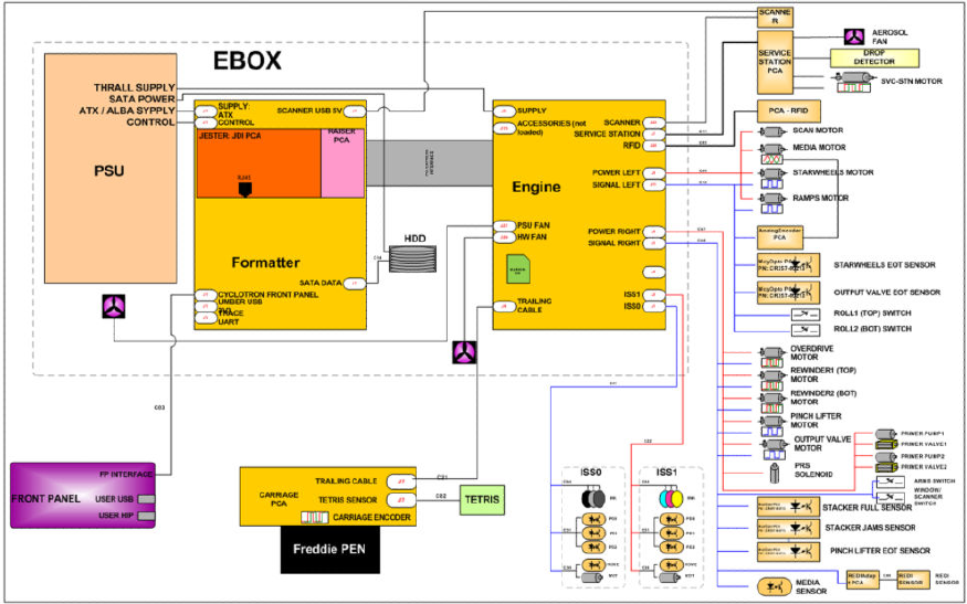
Theory of operation
Schematics
Electronics are based on 3 main components:
●E-box - contains the power supply and all the PCAs (driving the printer), plus the Ethernet port.
●Carriage PCA - drives the printhead.
●Front Panel - user interface and USB port.
The following diagram describes the connections between components and electronic boards and the data line
type for T920, T1500 and T2500.
Block Diagram
(HP DesignJet T3500 eMultifunction Series only)
6 Chapter 1 Printer fundamentals ENWW
ENWW Theory of operation 7

Block Diagram
(HP DesignJet T2500 and T3500 eMultifunction Series only)
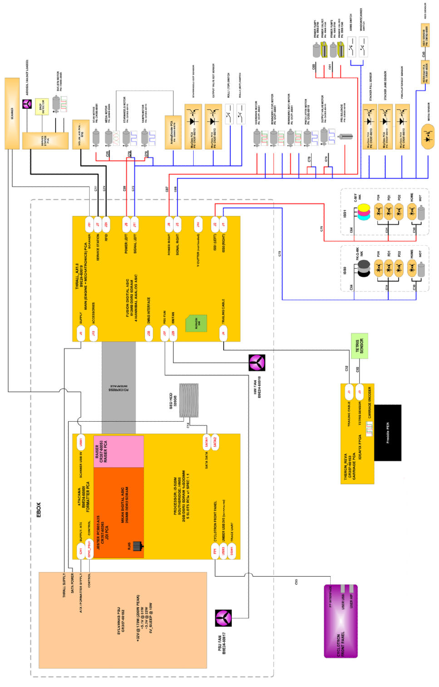
Wiring Diagram
(HP DesignJet T2500 and T3500 eMultifunction Series only)
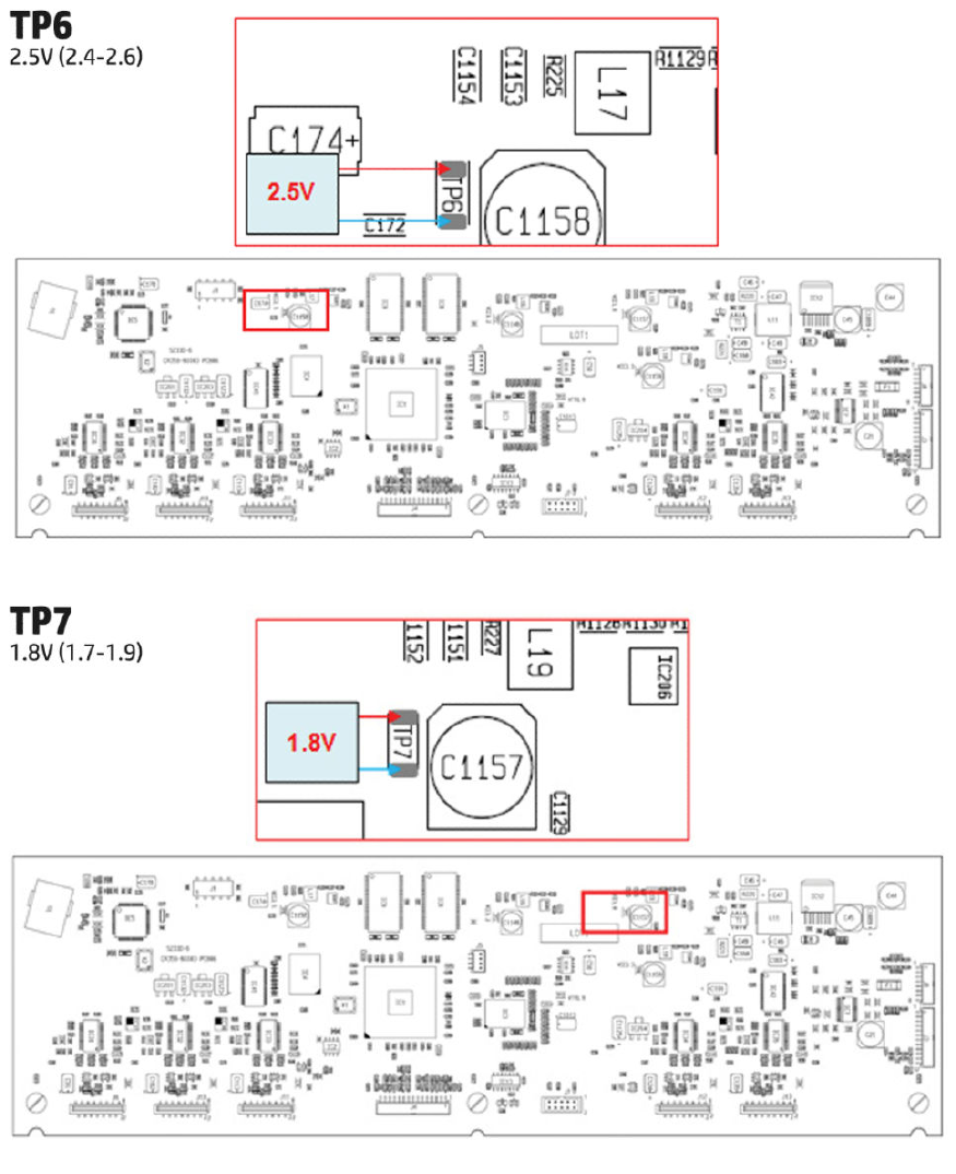
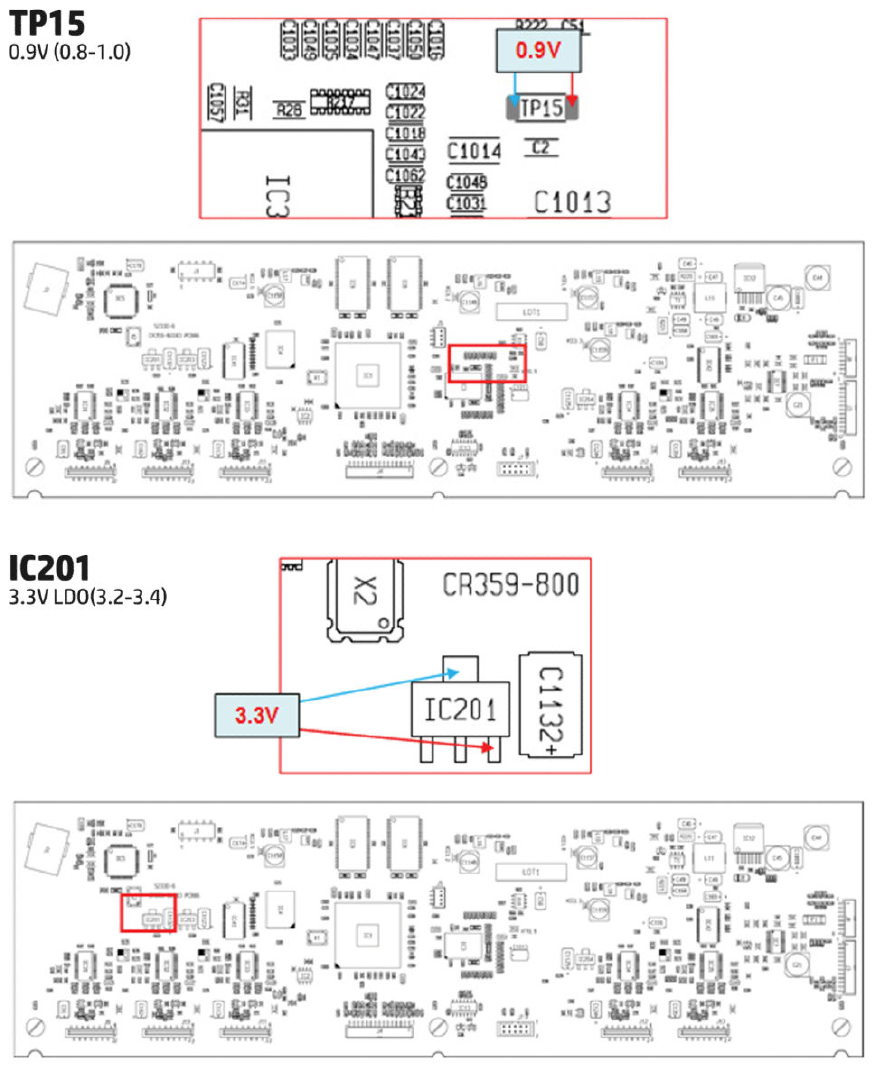
Scanner Controller Board Layout (SULG)
(HP DesignJet T2500 and T3500 eMultifunction Series only)
Voltage Min limit Max limit
TP1 5V-Main (Always on when there
is power to the board)
4.75 5.25
TP2 5V 4.75 5.25
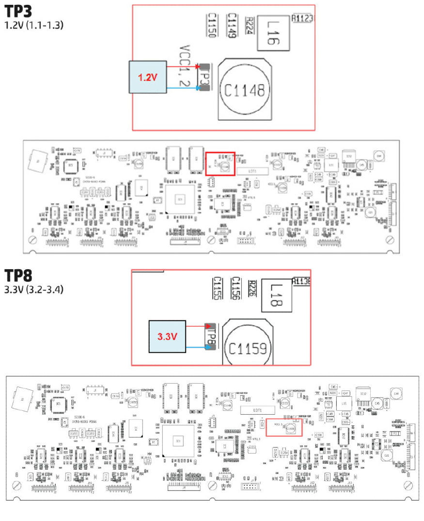
TP3 1.2V 1.1 1.3
TP8 3.3V 3.2 3.4
TP6 2.5V 2.4 2.6
TP7 1.8V 1.7 1.9
8 Chapter 1 Printer fundamentals ENWW
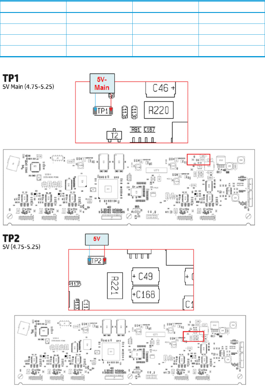
Voltage Min limit Max limit
TP15 0.9V 0.8 1.0
IC201 3.3VLDO 3.1 3.5
IC203 3.3VLDO 3.1 3.5
IC204 3.3VLDO 3.1 3.5
ENWW Theory of operation 9
10 Chapter 1 Printer fundamentals ENWW
ENWW Theory of operation 11
12 Chapter 1 Printer fundamentals ENWW
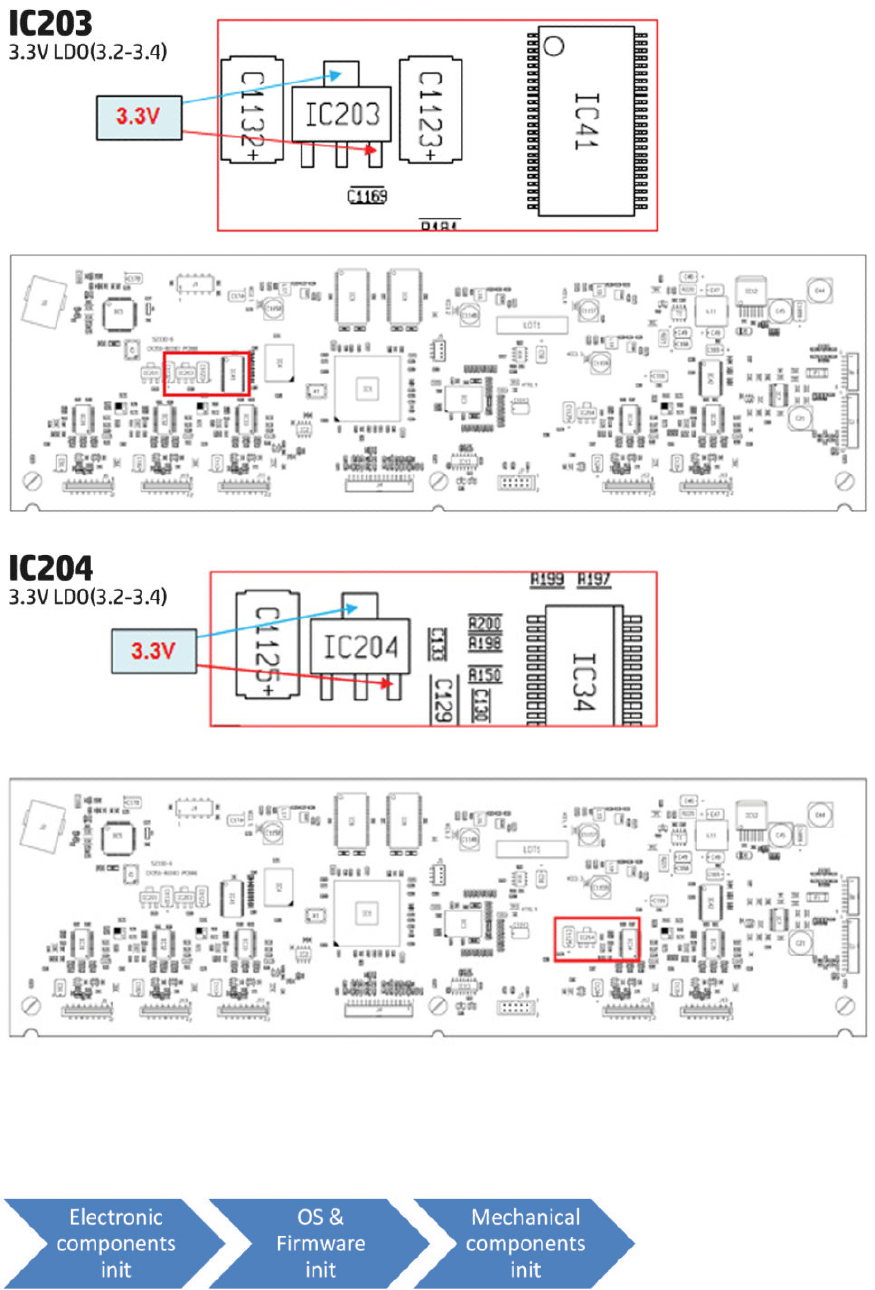
Printer Initialization
There are 3 main blocks to be initialized before the printer can be operated:
ENWW Theory of operation 13
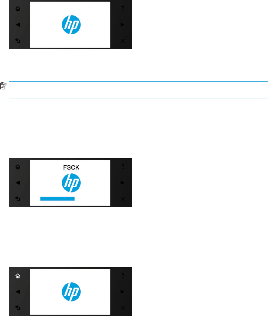
Electronic components init
1. The front panel shows a white background and blue HP logo.
2. The upper LED in the formatter is ON, indicating that the formatter has been initialized.
3. The middle LED in the formatter blinks, indicating that the HDD has been initialized.
NOTE: Steps 2&3 are the same when waking from Sleep Mode except the 3 LEDs are not on but; ON-
Blinking-OFF
OS & Firmware init
1. The OS is loaded into RAM. The Front Panel blinks for a second.
2. If boot up is after a bad power-o, the boot sequence automatically runs a le system check.
a. The Front Panel shows the FSCK, text.
b. First, FSCK runs on the root partition.
c. If FSCK is successful, the OS boots up from the root partition and runs FSCK on the data partition.
3. After FSCK, the OS nishes booting from the HDD.
4. The home button lights up to allow stopping the boot sequence, and entry to the diagnostics menu, see
Diagnostics, Service Utilities and Calibrations on page 179.
Mechanical components init
1. The Front Panel shows a black background with a blue circle in the middle. The “Initializing” message
appears. A progress bar shows the percentage of subsystems that have been initialized.
2. The printer moves the carriage from side to side to validate its position within the scan axis. The printer
initializes the service station, moving the caps from bumper to bumper.
14 Chapter 1 Printer fundamentals ENWW
3. The pinches move down into position.
4. T2500 and T3500 only: The printer will initialize the Scanner and start checking it.
5. The carriage and service station move to the home position
6. The printer checks the status of supplies and the printhead, and then initializes the Ink Supply Stations.
7. Servicing routines are launched. The routines refresh the printhead depending on the time that the printer
has been o. The Front Panel shows “Preparing Print System”.
8. The paper path subsystems are initialized by exercising the ramps and rewinder, checking if there is media
present over the Media Sensor.
9. At the end of the process, the home screen appears in the Front Panel.
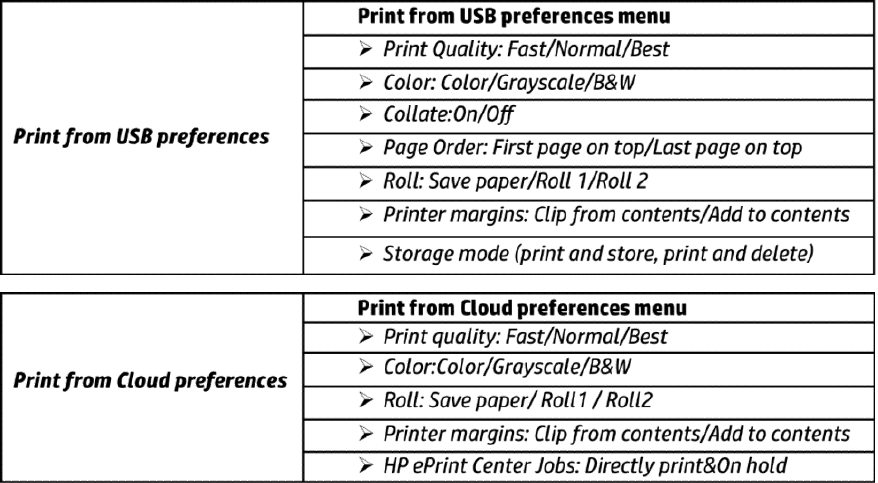
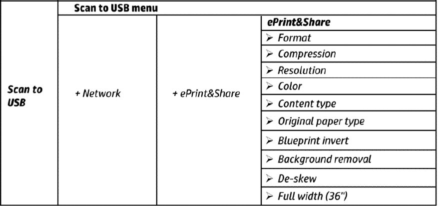
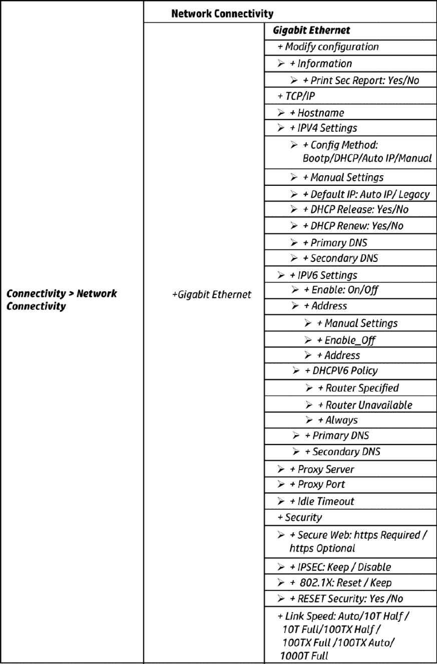
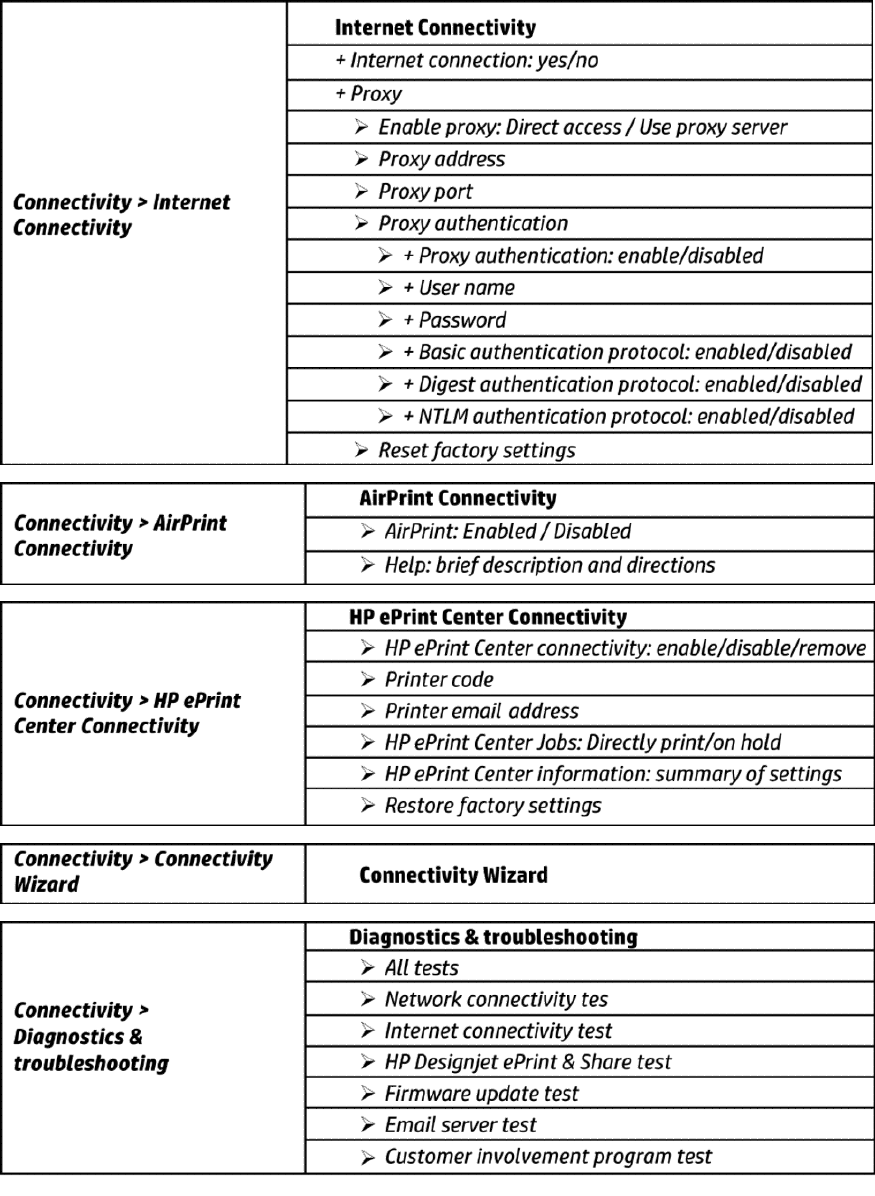
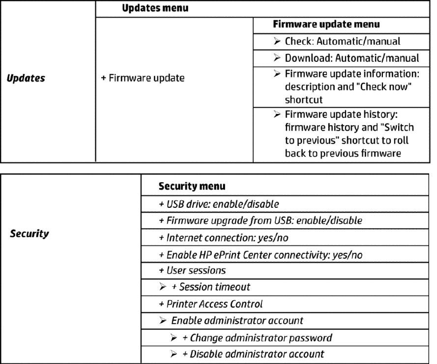
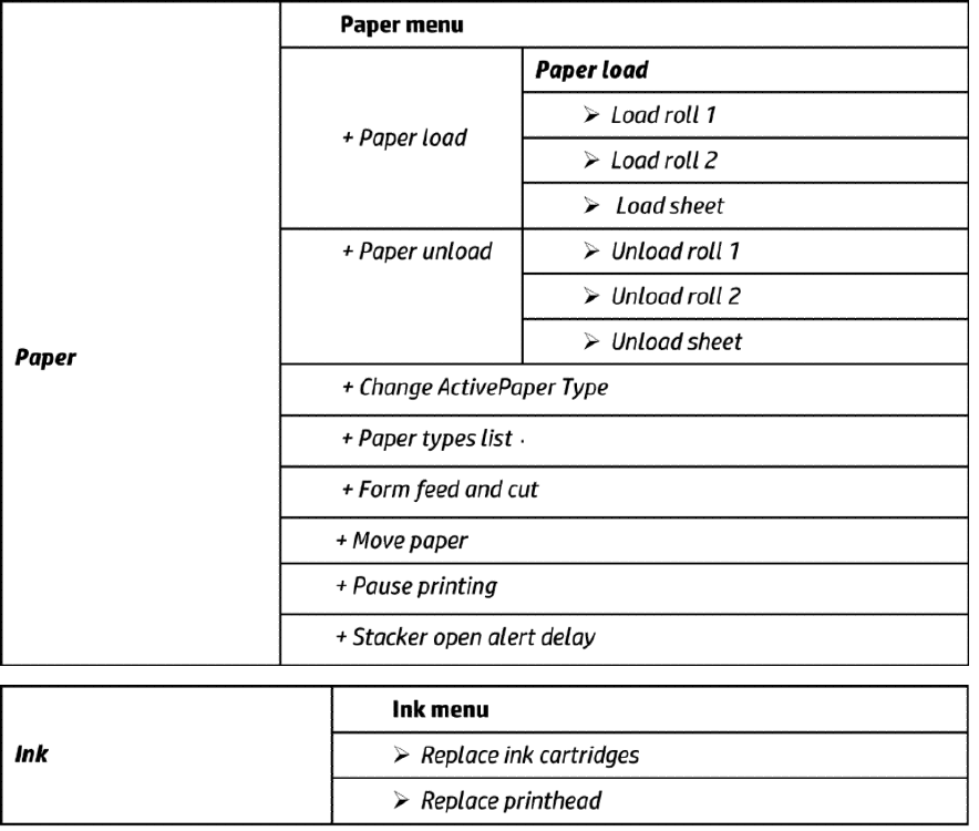
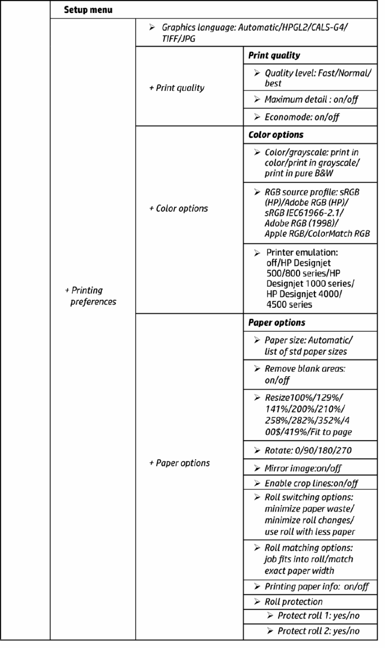
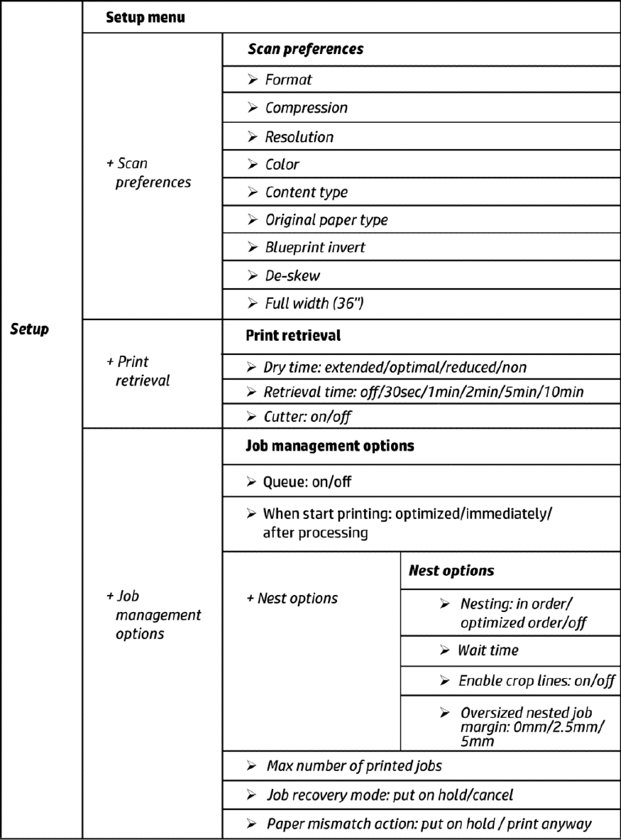
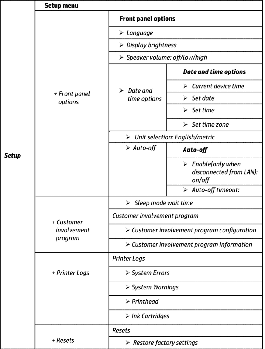
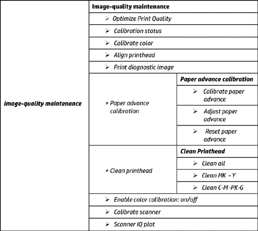
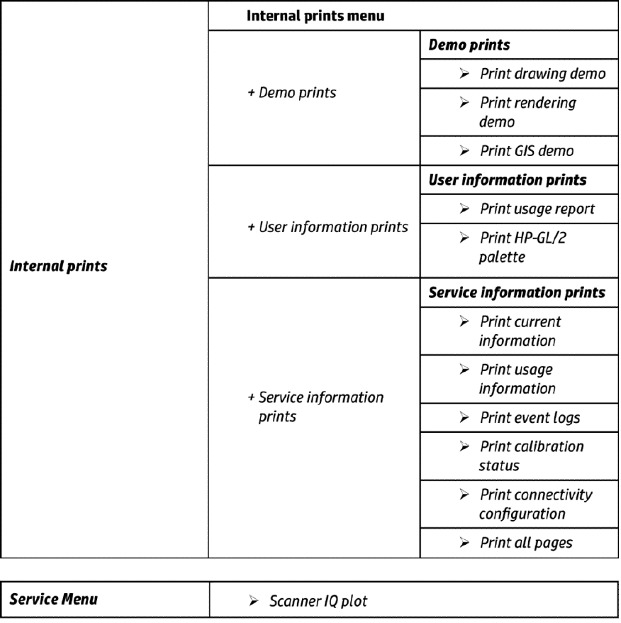
Front Panel Menu Map
The following tables show the front panel menu layout.
ENWW Theory of operation 15
16 Chapter 1 Printer fundamentals ENWW
ENWW Theory of operation 17
18 Chapter 1 Printer fundamentals ENWW
ENWW Theory of operation 19
20 Chapter 1 Printer fundamentals ENWW
ENWW Theory of operation 21
22 Chapter 1 Printer fundamentals ENWW
ENWW Theory of operation 23
24 Chapter 1 Printer fundamentals ENWW
ENWW Theory of operation 25
26 Chapter 1 Printer fundamentals ENWW
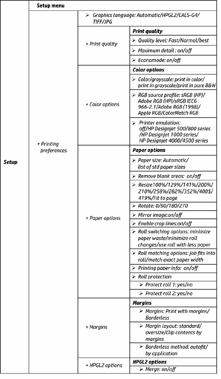
Front Panel Menu Map (T3500 only)
ENWW Theory of operation 27
HP 727 Printhead Start-up process
1. Insert cartridges: If the printhead is initialized during the installation of the printer, the printer will rst
check for new supplies.
28 Chapter 1 Printer fundamentals ENWW
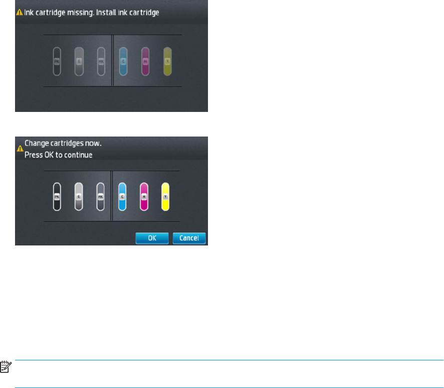
“Ink cartridge missing. Install ink cartridge.”
”Change cartridges now. Press OK to continue.”
If the printer still needs to purge the ink tubes and there are cartridges already installed in it, the printer will
reject the supplies, reporting them as “Not Valid” and will request to “remove and reinsert” the supplies.
Cartridges can be reseated in order to be accepted by the printer before the tubes are purged. This allows
the printer to do a full validation of the supply before running a tube purge.
If the cartridges used for installation do not contain the required 60cc of ink for purging, the printer will
report that “cartridge is not valid for setup”.
NOTE: keep in mind that to initialize a printhead you need 40ml of Matte Black ink and 30ml of ink for the
rest of the colors. To purge ink tubes, you need 60cc of all colors. If in doubt, use 130ml cartridges.
ENWW Theory of operation 29
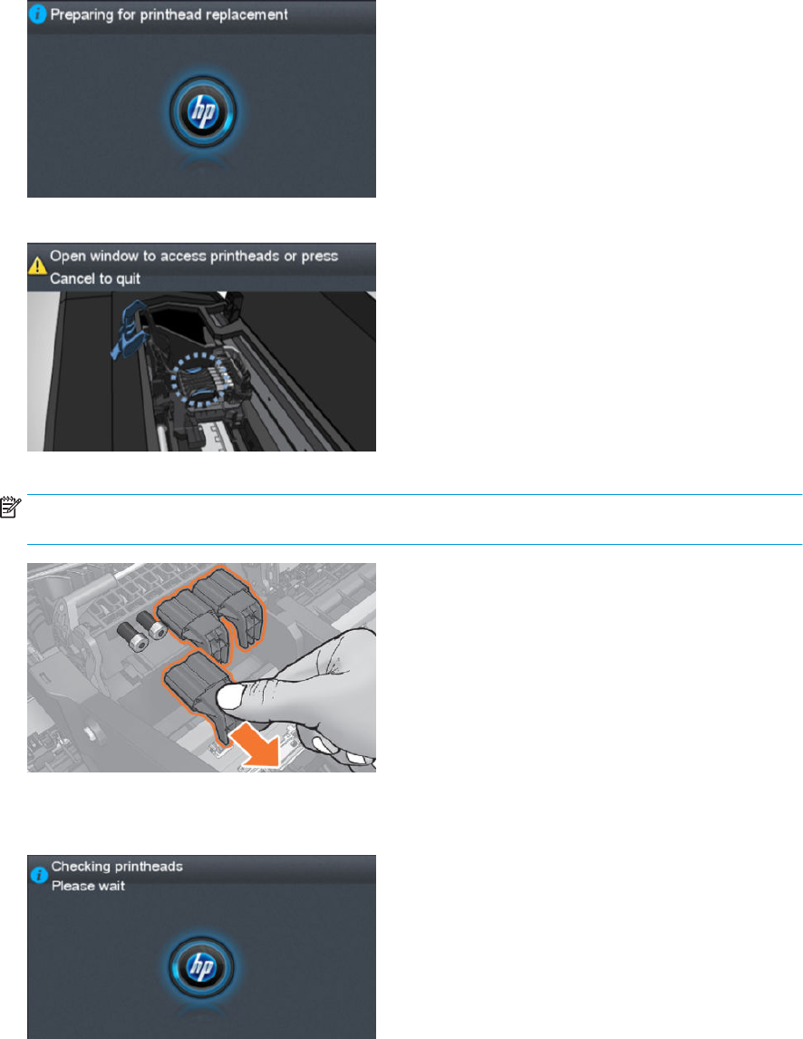
2. After inserting the cartridges, the printer requests the printhead.
“Preparing for printhead replacement”
“Open window to access printheads or press Cancel to quit”
NOTE: If printhead insertion is completed during printer installation, remember to remove the orange
caps.
3. After inserting the printhead, the printer will check electronic connections. If the check fails, the printer will
ask to reseat the printhead.
“Checking printheads. Please wait”
30 Chapter 1 Printer fundamentals ENWW

4. Once it is certain that the printhead is recognized, the printer will purge the ink tubes if they are empty. It
will also ll the printhead.
“Preparing the printhead for rst usage”
If the process nishes OK, the printer will ag the printer tubes and printhead as lled with ink.
If during the process the printer detects that a cartridge has been removed it will show the message “A
supply has been removed” and it will go back to step 1.
After this step, all ink tubes should be completely lled. The circles on top of the printhead should also look
lled.
5. At this point, the printer will run 2 checks to validate the start-up: rst will check for ink pressure and
second for printhead temperature while spitting. If the pressure fails, it will be logged as a SE 93.0.n:10 in
the service plot (where n is the failing color). If the temperature check fails, it will be logged as a SE 93.2.n:
10 in the service plot (where n is the failing color). The SE are not shown in the front panel. In both cases,
the printer will request to Reseat the printhead. After the reseat the printer will try to ll again the tubes
and printhead by going to step 3.
n indicates the missing color:
●n=0 stands for photo black
●n=1 stands for gray
●n=2 stands for matte black
●n=3 stands for cyan
●n=4 stands for magenta
●n=5 stands for yellow
6. After this second trial, the pressure and temperature tests will be repeated. If the pressure fails, it will be
logged as a SE 93.1.n:10 in the service plot (where n is the failing color). If the temperature check fails, it
will be logged as a SE 93.3.n:10 in the service plot (where n is the failing color). The SE are not shown in the
front panel. In any case, the printer will move to step 3 and try to execute it.
ENWW Theory of operation 31
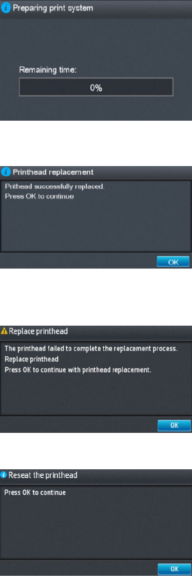
7. After the printhead and tubes are lled, the printer completes some printhead servicing to nalize the
initialization.
“Preparing print system”
If successful. If the printhead is properly initialized, the printer shows the following message:
“Printhead replacement. Printhead successfully replaced. Press OK to continue.”
If unsuccessful. If there is a problem the printer, depending on the problem, one of the two following
messages appears:
“Replace printhead. The printhead failed to complete the replacement process. Replace printhead. Press
OK to continue with printhead replacement.”
“Reseat the printhead. Press OK to continue.”
32 Chapter 1 Printer fundamentals ENWW
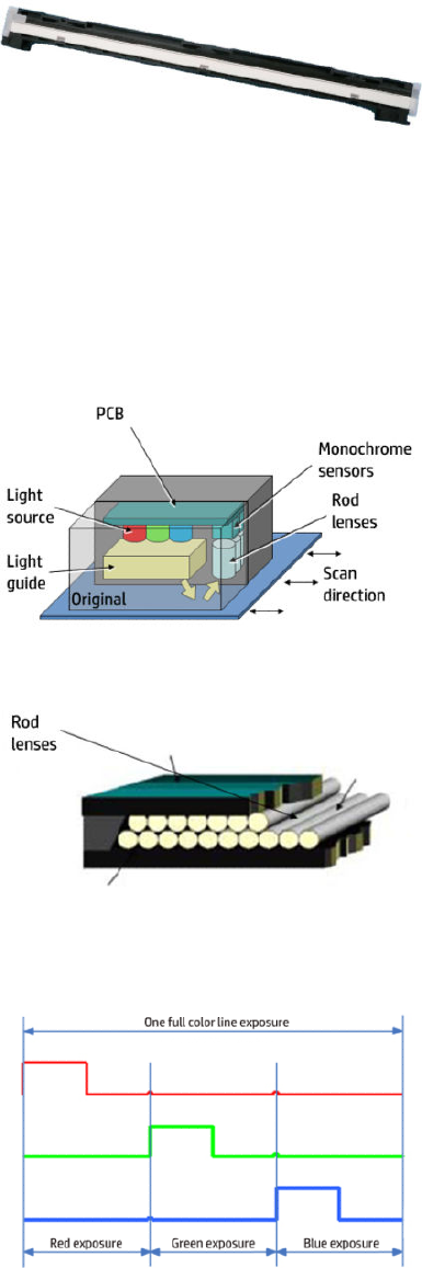
CIS Technology
Example of a CIS Element, Contact Image Sensor:
The CIS Element consist of 3 major parts:
●Sensor
●Lens
●Light source
The Light source is 3 RGB LEDs that are lit one at a time. The sensor consists of 10368 individual monochrome
sensors.
The purpose of the lens is to channel the light from the “pixels” on the image to the sensors. There is no
magnication in the lens (1x1).
Due to the very short focal length, the focus depth is limited. The original has to be in contact with the surface of
the glass plate in order to be in focus.
The LED’s ash one at a time, capturing one color at a time.
ENWW Theory of operation 33

2 Troubleshooting
●The front panel
●Service keys combination
●Troubleshooting tree (T920 and T1500 only)
●Product Troubleshooting trees (T2500 and T3500 only)
●Scanner Troubleshooting Tree
●Scanner CIS Troubleshooting
●Troubleshooting using board LEDs
●Paper handling problems
●Ink supply problems
●Print-quality problems
●Connectivity problems
●Scanning Problems
●HP 727 Printhead Troubleshooting
●Videos for replacing CSR parts and HP 727 printhead
●Firmware upgrades
34 Chapter 2 Troubleshooting ENWW
The front panel
The front panel is located on the front right of the printer. It gives you complete control of your printer: from the
front panel, you can print, view information about the printer, change printer settings, perform calibrations and
tests, and so on. The front panel also displays alerts (warning and error messages) when necessary.
For more information about front panel, refer to the users guide.
Sleep mode
Sleep mode puts the printer into a reduced power state after a period of inactivity, turning o the front panel
display to save energy. Printer features can be enabled from this mode, and the printer maintains network
connectivity, waking up only as necessary. The printer can be woken from sleep mode by the Power button, by
sending a print job, or by opening the window, the roll cover, or the stacker cover. The printer wakes up in several
seconds, more quickly than if it is completely turned o. While in sleep mode, the Power button blinks.
To change the time that elapses before sleep mode, press , then , then Setup > Front panel options
> Sleep mode wait time. You can set a time between 5 and 240 minutes; the default time is 30 minutes.
Printer Monitoring (with thde Print Spooler) and Remote Printer Management with the HP Utility and Web
JetAdmin continue to be available during sleep mode. Some remote management tasks oer the option of
remotely waking up the printer if needed to perform the task.
Other Power States
Besides sleep mode, the printer has 5 dierent power states (including ready and sleep). Depending on the
power state, the printer has dierent subsystems wake up and ready for use.
ENWW The front panel 35
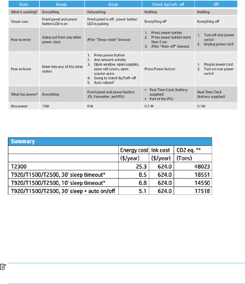
(1) After 50 cycles of sleep-mode, the printer performs an auto-reboot, done between 22h00 and 06h00.
Background information
* Assumes printer is never switched o.
** Total DECC equiv. CO2 footprint of all IB during 5 years May-2013 / May-2018 assuming 20%, switches-o
printer or oce power and 33% programs schedule on/o.
Auto-o
Auto-o sets the printer to "soft-o" mode after the period of time set by the user can in the Front Panel. This
feature is disabled when the printer is connected to the LAN, and in this case, the printer can't go to soft-o
automatically. The default value from factory for the Auto-o time out is 120min.
NOTE: In some situations this can be confusing since printers without LAN will be set to o automatically
during the night. Furthermore, once the printer has been switched o automatically it needs to be turned on with
the Blue Power Button on the printer. Switching on from the rear button will not wake up the printer.
36 Chapter 2 Troubleshooting ENWW

Service keys combination
Entering the User Diagnostics Menu
1. Go to Printer Main Menu.
2. Go to Diagnostics Menu.
3. Type code “1714”.
4. Go to Diagnostic Tests.
5. Allow the printer to reboot.
Printer will remain in “User Diagnostics Menu” until it’s setup to go back to Printer mode.
To go back to Printer mode:
1. From “User Diagnostics Menu” go to “Reboot in printer mode”.
2. Allow the printer to reboot.
The “User Diagnostics Menu” has a limited set of Diagnostics and allows only to perform the following actions:
●Scan Axis Motor on page 335
●Paper Drive Test on page 186
●Electronics Module Test on page 187
●Sensors Test on page 191
●Stacker Jam Sensor Test on page 196
●Stacker Capacity Sensor Test on page 196
●Stacker Empty Sensor Test on page 191
●Output Valve Test on page 192
●Pinches Lifter Test on page 194
●Stacker Ramps Test on page 194
●Stacker Overdrive Test on page 195
●Ink Delivery System (IDS) Test on page 196
●Service Station with Drop Detector on page 339
●Enable I/O Interfaces Utility on page 200
●Unit Information Utility on page 200
Entering the Diagnostics Menu when booting the printer
1. Make sure the product is switched o with the Power button on the side of the Front Panel, and not with
the power switch on the back of the product.
2. Press and release the Power key to switch on the product.
ENWW Service keys combination 37

3. Wait for the Home button light to come on.
4. Press the Home button; the button will acknowledge by blinking.
5. All LEDs will come on; press and release them one after another:
●The Cancel icon
●The Home icon
●The Help icon
NOTE: Do not push the icons all at the same time, push each one in the order shown above and release
each icon before pressing on the next icon
6. The 6 buttons on the Front Panel then blink 4 times; wait until the product completes the initialization
sequence and shows the Diagnostics menu.
7. In the Diagnostics menu, scroll up and down sliding a nger vertically on the Front Panel, and press on the
desired option.
NOTE: The Diagnostic Tests and Utilities work in a special mode that does not require the full initialization of
the product. Therefore, whenever a test is nished a test, switch o the product and switch it on again before
printing, or executing another test.
NOTE: A quick press of a button on the Front Panel frame may not be recognized by the product. When
pressing a button, be sure to press it for about 1 second.
NOTE: If the product hangs up during a test; switch the product o and restart from step 1.
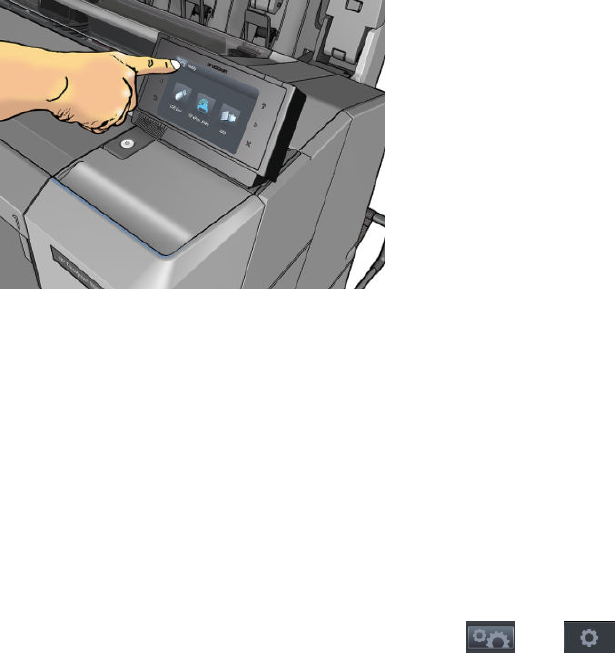
Entering the service utilities menu
1. From the home screen, select the Information icon in the top left corner. For information about the Front
Panel keys, see using The front panel on page 35 or:
2. From the product information area, press the main menu / tool icon on the bottom right corner of the
screen.
3. Scroll down to the lowest menu option and select the Service menu option.
4. Enter the 4-digit 1st level access code “3174” and press OK.
5. Select the Service utilities menu option.
6. From the service utilities menu you can scroll up and down to see all the available utilities. Press on the
selected menu option.
38 Chapter 2 Troubleshooting ENWW

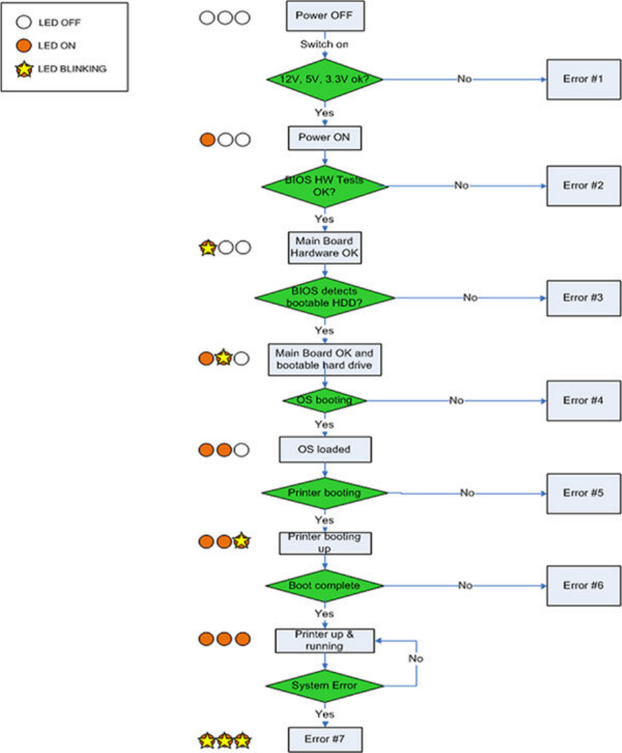
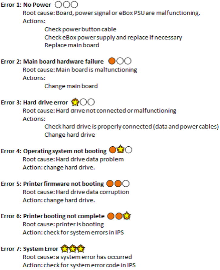
Troubleshooting tree (T920 and T1500 only)
As a general approach, the following tree should be followed to troubleshoot any issue. This helps understand at
which point the problem was caused. The tree is sequential; before checking a subsystem, the previous steps
need to be working. Once a sub system is identied as causing the problem, the service and utilities related to
that component can be used to troubleshoot further. See Diagnostics, Service Utilities and Calibrations
on page 179.
ENWW Troubleshooting tree (T920 and T1500 only) 39
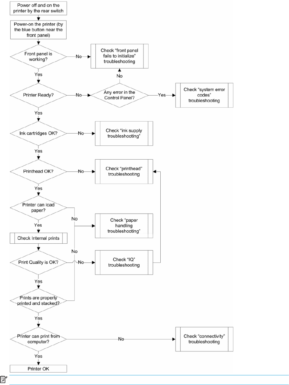
NOTE: Once an issue is conrmed, check that printer has latest rmware installed.
40 Chapter 2 Troubleshooting ENWW
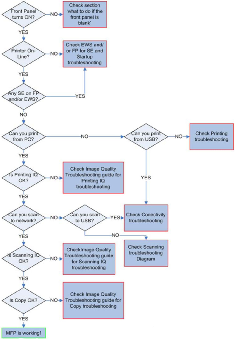
Product Troubleshooting trees (T2500 and T3500 only)
Figure 1-1 Troubleshooting
ENWW Product Troubleshooting trees (T2500 and T3500 only) 41

Scanner Troubleshooting Tree
Figure 1-2 Scanner Troubleshooting
42 Chapter 2 Troubleshooting ENWW
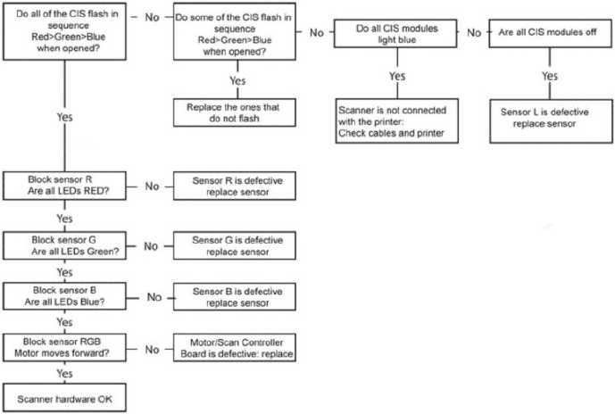
Scanner CIS Troubleshooting
Figure 1-3 Scanner Troubleshooting
ENWW Scanner CIS Troubleshooting 43
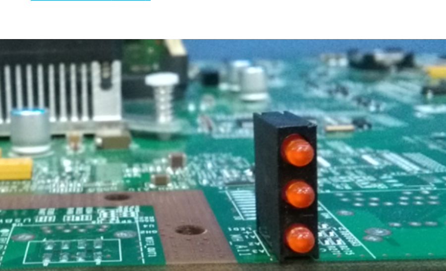
Troubleshooting using board LEDs
All the printer boards have diagnostic LEDs to help in the troubleshooting. Although some LED information is
redundant and also known by the printer rmware, using the board LEDs can be very useful when trying to
diagnose power or communication problems. The following sections provide information on the physical location
and meaning of each board’s diagnostic LEDs.
For further information regarding electric and electronic interactions, see the subsystems’ block diagrams in
section Theory of operation on page 6.
Board name: Formatter PCA
Meaning of LEDs:
44 Chapter 2 Troubleshooting ENWW
ENWW Troubleshooting using board LEDs 45
46 Chapter 2 Troubleshooting ENWW
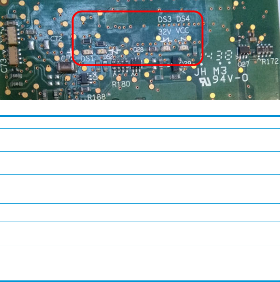
Board name: Carriage PCA
Meaning of LEDs:
State Orange LED DS3 Orange LED DS4 Red LED DS1 Orange LED DS2
32V Power input OFF OFF ?? ?? ??
Vcc Power OFF ?? OFF OFF OFF
32V Power input ON ON ?? ?? ??
Vcc Power ON ?? ON ?? ??
FPGA not programmed ?? ON ON ON
FPGA programmed in
Reset State
?? ON OFF OFF
FPGA out of reset but no
clock
?? ON Regular blinking Not blinking
FPGA out of reset, HCI
clock OK, HCI not
initialized
?? ON ?? Slow blinking
FPGA out of reset, HCI
clock OK, HCI Id initialized
?? ON ?? Fast blinking
FPGA out of reset, PLL
unlocked
?? ON Two-pulse blinking ??
ENWW Troubleshooting using board LEDs 47
Board name: Jester PCA
Meaning of LEDs:
There is only one LED left on Jester. It is a Green/Red LED able to code the following states:
Board status LED status Period
Some Voltage/Temperature out of range Fix Red -
Monokhan does not respond (possibly in
reset)
Slow Red 0.4 Hz
Mismatching Hardware/Software version Quick Red 5 Hz
Monokhan unexpected reset Fix Green -
Normal operation Quick Green 5 Hz
48 Chapter 2 Troubleshooting ENWW
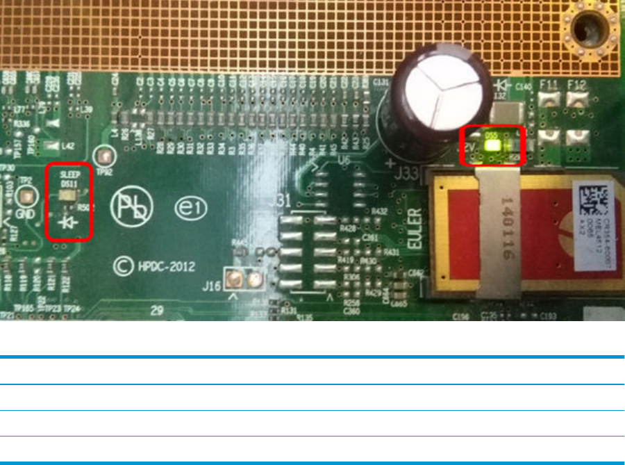
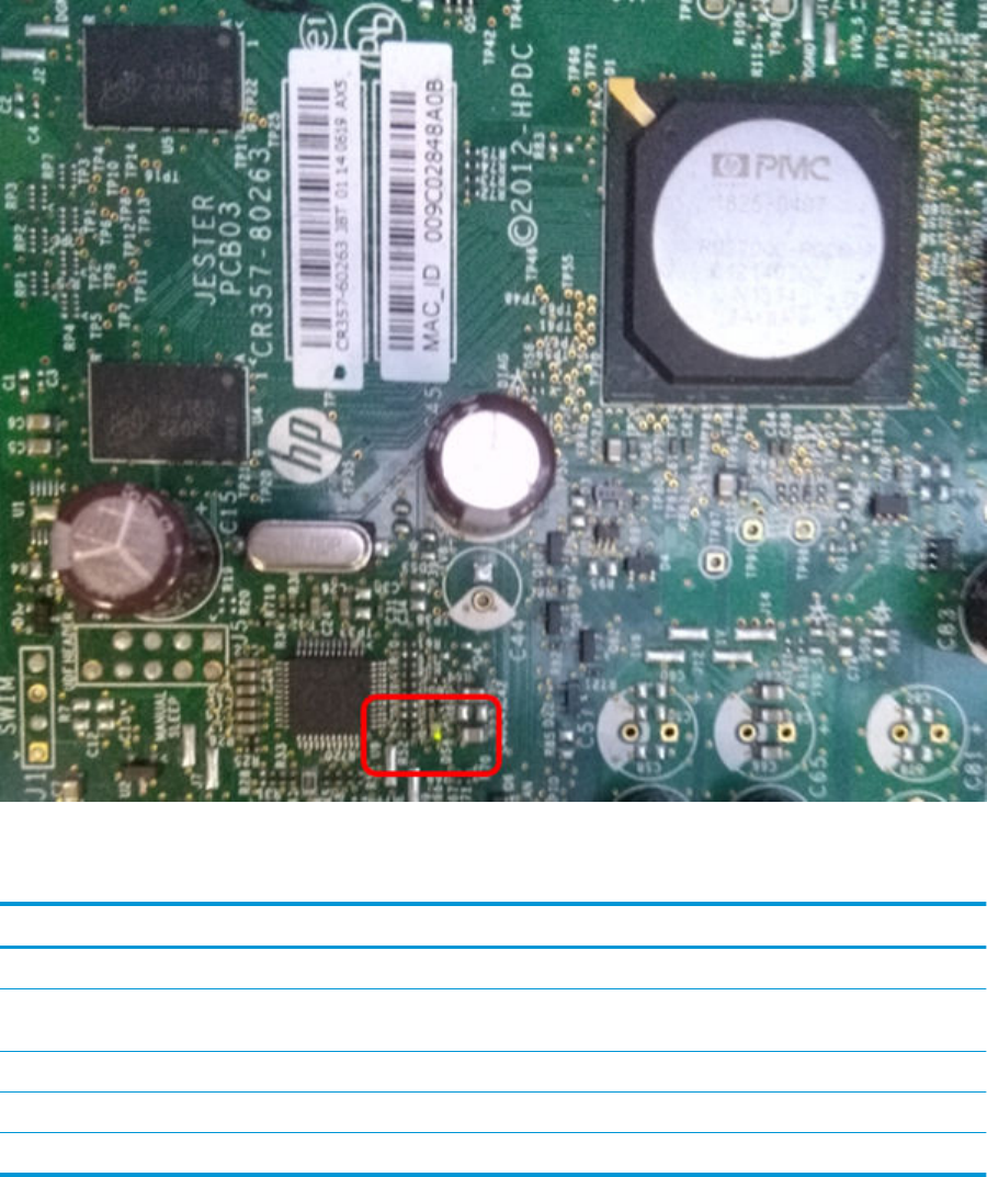
Board name: Engine PCA
Meaning of LEDs:
State Green LED DS5 Green LED DS11
32V Power input OFF O O
32V Power input ON On O
Sleep mode activated O On
ENWW Troubleshooting using board LEDs 49
Paper handling problems
●The paper has jammed in the print platen
●The paper has jammed in the stacker
●Thin paper is jamming in the stacker
●High density plots jamming in the stacker
●Several stacker paper jams
●Stacker capacity lower than expected
●The stacker detects "Stacker is full" permanently
●The stacker detects "Stacker jam" permanently
●The printer rejects the paper during paper load
●Prints do not fall neatly into the basket
●Using the stacker
●The paper type is not in the list
●The printer printed on the wrong paper type
●An “on hold for paper” message
●The printer displays out of paper when paper is available
●The print remains in the printer after printing has completed
●The cutter does not cut well
●The roll is loose on the spindle
●The roll is unloaded unexpectedly
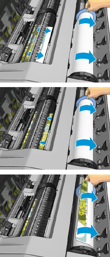
The paper has jammed in the print platen
When a paper jam occurs, you normally see the Possible paper jam message in the front panel display, and a
system error 81:01 or 86:01.
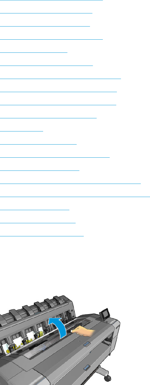
1. Open the window.
50 Chapter 2 Troubleshooting ENWW
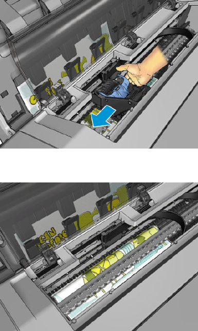
2. Move the carriage manually to the left side of the printer, if feasible.
3. Go to the paper path.
ENWW Paper handling problems 51
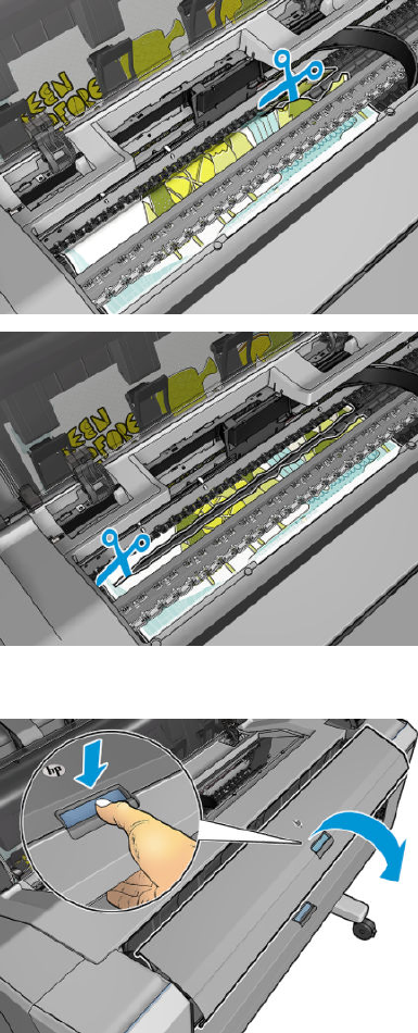
4. Cut the paper with a pair of scissors.
5. Open the roll cover.
52 Chapter 2 Troubleshooting ENWW
6. Manually rewind paper onto the roll.
ENWW Paper handling problems 53
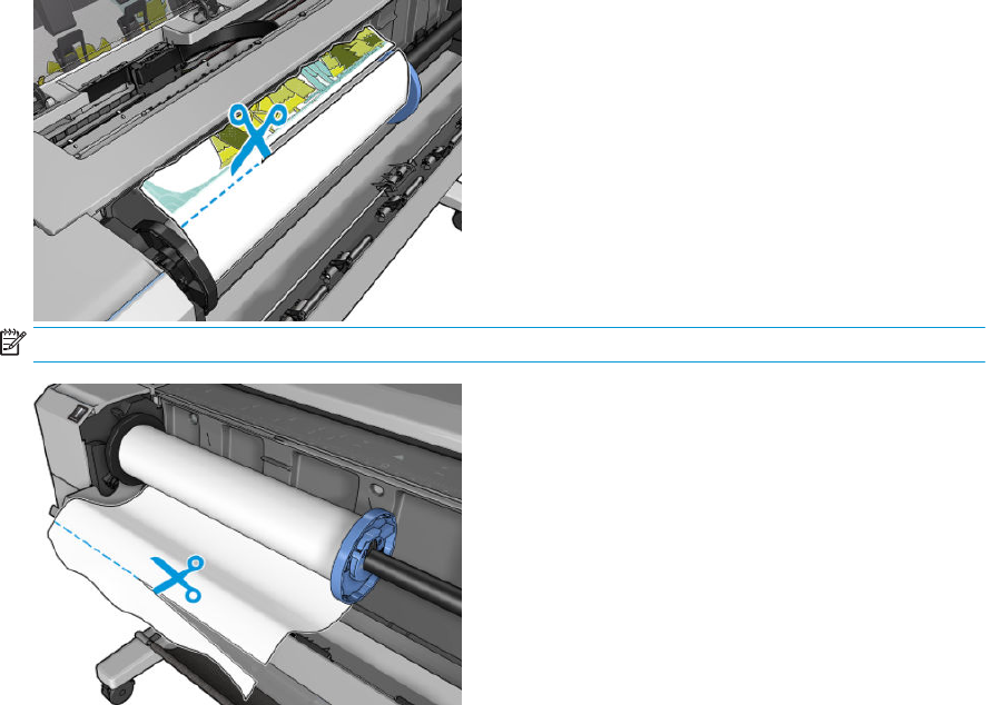
7. If the leading edge of the paper is ragged, trim it carefully with scissors.
NOTE: In the T3500 the guide can be used for cutting.
54 Chapter 2 Troubleshooting ENWW
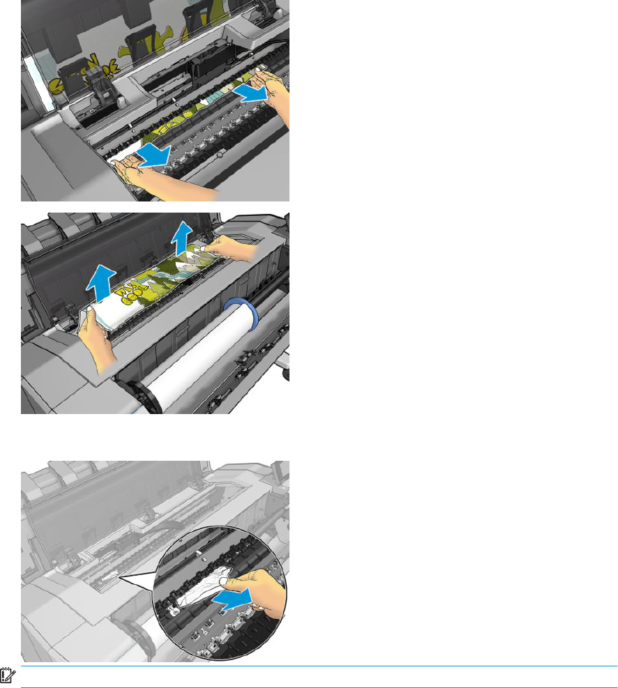
8. Remove the paper left in the printer.
9. Make sure you have removed every fragment of paper.
IMPORTANT: Remove remaining paper by carefully pulling it out in the direction of the paper axis.
ENWW Paper handling problems 55
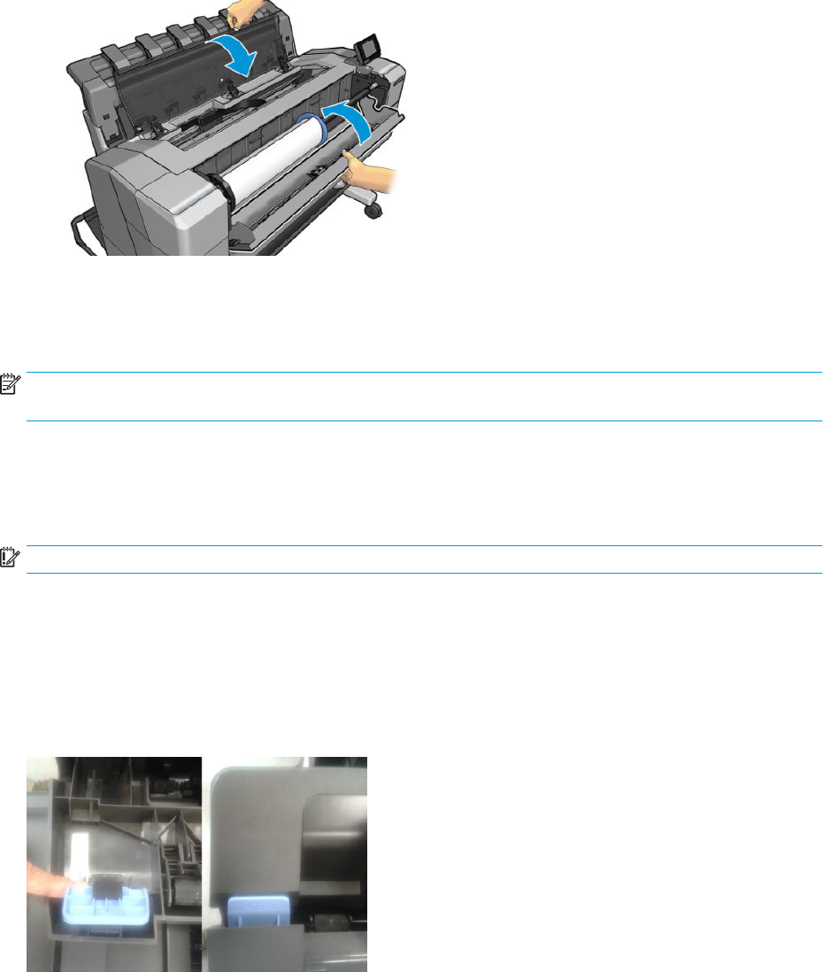
10. Close the window and the roll cover.
11. Restart the printer by holding down the power button for a few seconds, or by turning the power switch at
the rear o and then on.
12. Reload the roll, or load a new sheet.
NOTE: If you nd that there is still some paper causing an obstruction within the printer, restart the procedure
and carefully remove all pieces of paper.
The paper has jammed in the stacker
When a stacker jam is detected, printing is paused, and the front panel asks you to open the stacker cover and
clear the jam by pulling out the paper.
IMPORTANT: Remove remaining paper by carefully pulling it out in the direction of the paper axis.
When the stacker arms cover is closed and the printer detects no jammed paper, the front panel requests
conrmation to continue printing.
Thin paper is jamming in the stacker
When using a media thinner than 75gsm, the blue lever needs to be pulled forwards so that there is a larger gap
between the arms and stacker tray when the arms are closed.
56 Chapter 2 Troubleshooting ENWW
After printing with thin media, remember to return the blue lever so that there is a small gap between the arms
and stacker tray.
High density plots jamming in the stacker
If you are printing high-density plots (over 15ngrs ink density) with media below 80grs/m2, and you encounter
that plots have problems curving at the end of the stacker, or do not stack properly, and cause jams:
●Use Manual mode.
●Print to the basket.
●Use thicker media; over 80grs/m2.
ENWW Paper handling problems 57

●Use the CR357-67089 “Stacker tray ller” (CSR)
To improve the performance of the stacker when printing high density graphic content customers can use
the “Stacker tray ller” that guides stacker paper exit.
Place the parts of the Stacker tray ller as illustrated below:
Several stacker paper jams
Call agent:
1. Ask customer for Media type used and plot content.
2. Ask customer to check there is free space between top of the stacker and the wall.
3. Ask customer to check if one or several wheels of the arms cover is stuck in the paper path.
4. Exclude the cause to be any of the previously described issues. See Thin paper is jamming in the stacker
on page 56 and High density plots jamming in the stacker on page 57.
A root cause can be one or several wheels of the arm cover stuck in the paper path.
Ask the customer to perform the following actions:
5. Check that no cable routing is blocking the paper path.
6. Remove all paper from the stacker.
7. Detach the stacker arms cover from the printer.
8. Visually check that there are no missing wheel supports in the stacker cover (there are 25 wheel supports).
9. Shake the stacker cover a couple of times so all the wheel supports can move freely.
10. Ensure that all wheel supports in the cover can rotate freely (by pushing them, and checking that they
return to their position). If any of them are stuck, try to move slightly to free them.
11. If any of the wheel supports are stuck or are missing, send a new stacker arms cover to the customer.
12. If all the wheel supports are free and there are none missing, then arrange an on-site visit with a new
stacker and stacker cover arms.
Service engineer:
Items required:
Take a stacker
Take stacker cover arms
58 Chapter 2 Troubleshooting ENWW
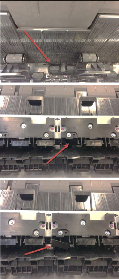
1. Remove all paper from the stacker.
2. Detach the stacker cover from the printer.
3. Visually check that there are no missing wheel supports in the stacker cover (there are 25 wheel supports).
4. Shake the stacker cover a couple of times so all the wheel supports can move freely.
5. Ensure that all wheel supports in the cover can rotate freely (by pushing them, and checking that they
return to their position). If any of them are stuck, try to move slightly to free them.
6. If any of the wheel supports are stuck or are missing, send a new stacker arms cover to the customer.
7. If all the wheel supports are free and there are none missing, check that there are no free or misplaced
pieces at the bottom of the stacker (pinches, rst wheel holder, wheels, etc.).
ENWW Paper handling problems 59
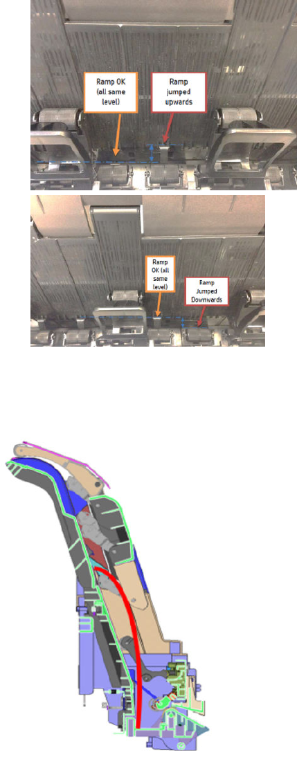
8. Check that Ramps are broken are not broken and are aligned.
9. Report root cause in cso and change Stacker.
Stacker capacity lower than expected
Stacker capacity is dened as up to 50 pages (T920/T1500/T2500), and 100 pages (T3500), A1/D size line
drawing plots in landscape on bond media, but stacker capacity depends on media thickness and page size. If
you are printing plots shorter than A1 and you experience a reduction in the stacker capacity because they
collapse and the curling lls the available stacking space:
●Try to increase the length of the plots when printing A2 and A3 sizes:
60 Chapter 2 Troubleshooting ENWW
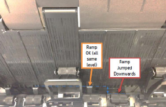
–Print A2 sizes in portrait position, using low-width rolls or nesting to minimize waste of paper.
–For A3 size, group dierent jobs in the same plot.
The stacker detects "Stacker is full" permanently
Even when there are no pages in the stacker, it detects that is it full.
●Remove the stacker arm and check the stacker wheels. If you nd a stacker wheel in the upper position,
get it down with the hand.
●Run the capacity sensor diagnostic.
●Run the ramps motor diagnostic.
●Check that when the ramps are up all are at the same height.
If ramps are not aligned, replace the stacker.
●Run the capacity sensor diagnostic. If it fails, replace Hand o Assy sensor.
The stacker detects "Stacker jam" permanently
Even when there are no pages in the stacker, it detects a jam.
●Run the capacity sensor diagnostic. If it fails, replace Hand o Assy sensor.
The printer rejects the paper during paper load
If the roll load process is too long and unsuccessful, check the following items:
●Roll paper is properly inserted in the spindle and pressed uniformly by the hubs.
●The core of the roll paper is not misplaced. If this is the case, try to correct its position.
●Check if the black hub of the spindle is damaged. If any part of the spindle is damaged, it could cause roll
load problems.
If the roll aected is from a polyester or lm type, it is possible that the edges of the paper are not properly
detected during the paper load process:
●Upgrade to the latest FW release to solve the problem, as the paper load algorithm has been improved.
Prints do not fall neatly into the basket
●Ensure that the network and power cables are not getting in the way.
●Ensure that the basket is correctly installed.
ENWW Paper handling problems 61
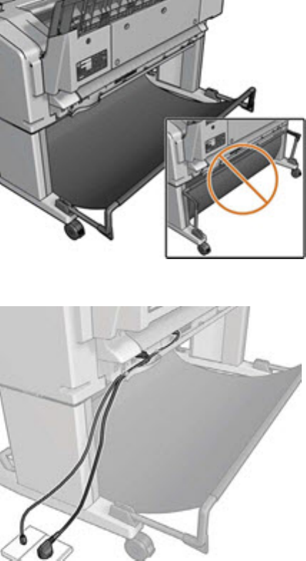
●Ensure that the basket is open.
●Ensure that the basket is not full.
●Ensure that the paper is not jammed.
●Paper often tends to curl near the end of a roll, which can cause output problems. Load a new roll, or
remove prints manually as they are completed.
If you see the message Please remove the print from the basket and press OK to continue, empty the basket,
check that there is no paper in the path to the basket, then press OK. The printer checks that the problem has
been xed.
Using the stacker
Installation
Prevent interruptions:
1. Open the basket; this indicates the clear space required at the back of the printer.
2. Route the cables to the side desired to attach the power cable; the left side is shown here.
62 Chapter 2 Troubleshooting ENWW
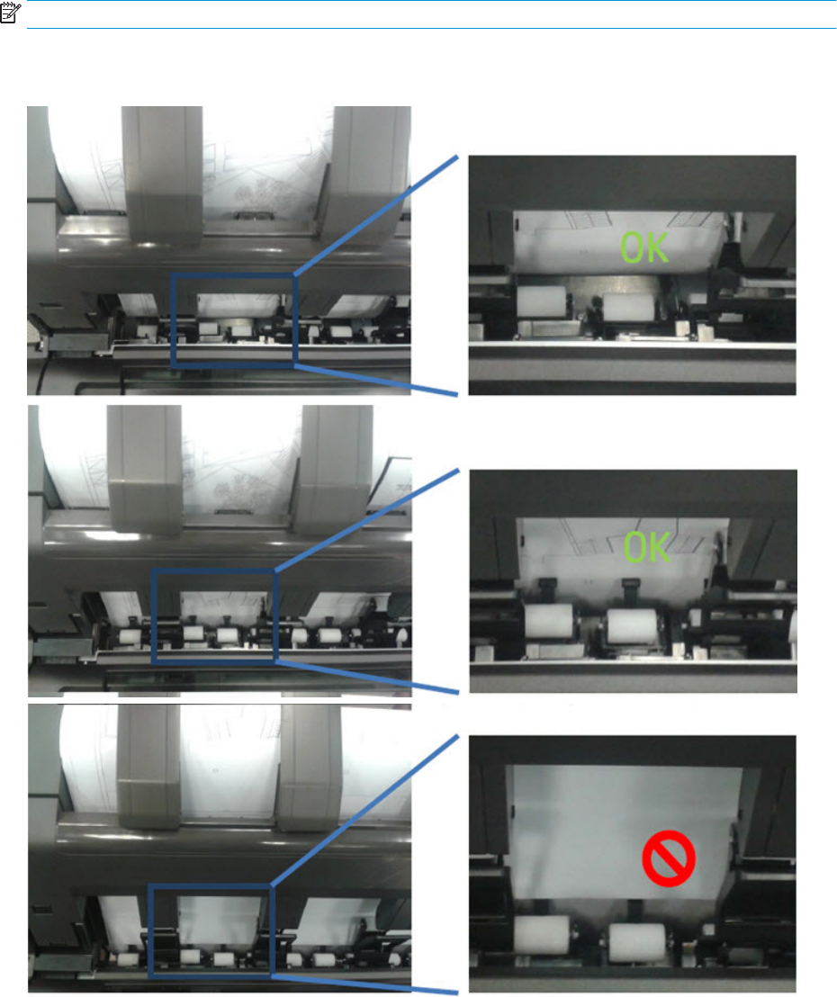
Removing prints from the stacker tray
Sheets can be removed from the stacker while printing. It is recommended to remove all prints when not
printing.
NOTE: Once removed, do not put prints back into the tray as this can collapse output.
If prints are replaced in the stacker tray; make sure that they reach the bottom of the stacker and don’t overlap
the page that is being printed, or the small black plastic piece.
ENWW Paper handling problems 63

Printing high quality prints
To obtain the best possible quality, consider:
High quality photo media graphics
Use instant dry photo media such as HP Instant Dry Photo or Satin paper to get ready-to-use and robust
prints.
Optimize quality when printing solid black areas; use Manual mode (print with the stacker open), and
carefully remove the output immediately after printing.
High quality matte media graphics
HP Heavy Coated Paper and Super Heavy Coated Paper reproduce deeper blacks and more saturated colors
than bond paper due to heavier coating.
When printing solid black areas, carefully remove output immediately after printing to prevent the next
print covering it.
Utilize full stacker capacity
The stacker is optimized for plain paper use (the most common size ISO A1/D). Capacity is up to 50 pages. When
the printer detects that the stacker is full, an alert appears to empty the stacker. The actual capacity may dier
depending on the combination of paper size printed and media type; for example, heavyweight coated is a media
with a higher grammage than plain paper, therefore the number of pages that the stacker can handle is less.
How to switch from stacker to basket and vice versa
The default output is the Stacker, however, switching to the basket is very easy:
In driver properties, select the Layout/Output tab, then in Output options select Basket for Delivery:
TIP: Also use this setting together with the Quick sets in the driver or as a driver default by going to Windows
Start, then Device and printers and editing the Printing properties.
TIP: At any time, the jobs appearing in the queue can be redirected and sent to either the stacker or the basket
by modifying the job setting in the Front Panel.
64 Chapter 2 Troubleshooting ENWW
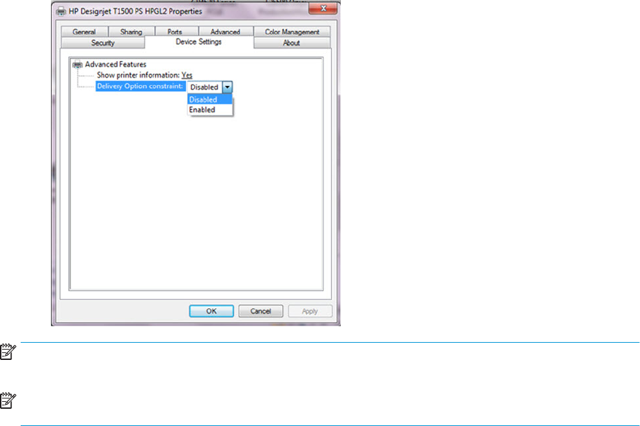
Manual mode
Manual mode is designed to help maximum print quality with photo media. The driver automatically enables
Manual mode when photo media is selected in the driver; the job now waits in queue for the stacker to open, and
to be activated. This ensures the stacker doesn’t touch the print while drying. If jobs are not required to be "Hold
for manual mode" there are 2 options:
1. Manual mode can be enabled/disabled in the Layout/options tab in the driver by clicking in the checkbox
Hold for manual printing with stacker open.
2. Disable the driver check for photo media so Manual mode is not enabled automatically. Press the Start
button, select Devices and Settings, and right-click the printer’s icon. Select Printer Properties. Select
Device Settings.
NOTE: When a job is put "On hold for manual mode" the printer doesn’t stop; while this job is waiting, and if the
stacker is closed, other jobs can still be sent and printed.
NOTE: After printing the job sent in Manual mode with the stacker open, the printer stops until the stacker is
closed, or another job is sent from the queue.
Resuming print interruptions
The stacker has a sensor to prevent unexpected behavior of the media in the tray, and ensure that the jams
never reach the printhead. Eventually, when prompted by the printer, it’s required to go to the stacker and
correct it by attening the paper. Once xed, printing will resume.
Media jam frequency may increase under certain conditions; when printing images with very high ink density on
light media like Bond or Coated under specic environmental conditions such as 30ºC-86ºF/70%. In such cases,
switching to a media with higher grammage such as HP Heavy Weight Coated can help to increase productivity.
The paper type is not in the list
To work with a paper that does not appear in the list in the driver or front panel, you can choose one of the other
papers in the list. However, you should at least choose a paper of the same type: transparent or translucent,
photo or bond, coated or technical.
ENWW Paper handling problems 65

NOTE: For photo paper, it is important to select a photo paper type, as the printer adjusts its use of ink for
photo paper.
Transparent or translucent lm
If your paper is a transparent lm (for example, a transparency), select paper type Film > Transparent/Clear lm.
If your paper is a translucent paper or lm (for example, technical paper), select paper type Film > Matte lm.
Photo paper
If your paper is a photo paper, use the Photo Paper category. For gloss or high-gloss paper, select paper type
Photo Gloss Paper. For semi-gloss, satin, pearl, or luster nishes, select paper type Photo Semi-gloss/Satin
Paper.
To increase gamut on photo paper, select paper type HP Universal Gloss Photo Paper or HP Universal Satin
Photo Paper, depending on the nish.
Bond and coated or technical paper
Your paper type selection for generic paper depends on the paper’s ink absorption capacity.
●For thin papers (< 90 g/m2) or uncoated papers (for example plain paper or bright white paper), select
paper type Bond and Coated Paper > Plain Paper. You can also select Recycled Bond Paper.
●For light coated papers (< 110 g/m2), select paper type Bond and Coated Paper > HP Coated Paper.
●For heavyweight coated papers (< 200 g/m2), select paper type Bond and Coated Paper > Heavyweight
Coated Paper.
Black ink is easily removed when touched
This happens when your paper is incompatible with matte black ink. To use an optimized ink combination, select
paper type Photo Paper > Photo Gloss Paper.
After printing, the paper has wrinkles or there is too much ink
Reduce the quantity of ink, or use thicker paper. Matte paper categories from thinnest to thickest are:
●Plain Paper
●Coated Paper
●Heavyweight Coated Paper
●Super Heavyweight Plus Matte Paper
TIP: If you load paper that is slightly thicker than the paper type you selected, the printer will use less ink than
usual for the loaded paper.
The printer printed on the wrong paper type
If the printer prints your job before you were able to load your desired paper, you may have Any or Use printer
settings selected for the Paper Type in the printer driver. In this case, the printer will print immediately on
whichever paper is loaded. Load your desired paper, and select your paper type specically in the driver.
66 Chapter 2 Troubleshooting ENWW

●In the Windows driver dialog: select the Paper/Quality tab, then select your paper type from the Paper Type
list.
●In the Mac OS X Print dialog: select the Paper/Quality panel, then select your paper type from the Paper
Type list.
NOTE: The driver default is Any for Mac OS and Use printer settings for Windows; they have the same eect.
An “on hold for paper” message
Based on a set of conditions that you can set when sending a job to a two-roll printer, the printer will decide
which of the loaded rolls of paper is more suitable to print the job. If there is no roll of paper available that meets
all the conditions, the printer will put the job on hold for paper. You can manually resume the job, forcing it to
print on a paper other than the one originally specied, otherwise it will stay on hold.
Which criteria are used to decide on which roll a job will be printed?
When a user sends a job, the desired paper type can be set (in the driver or in the Embedded Web Server). The
printer will print the job on a roll of paper of the chosen paper type that is large enough to print the drawing
without clipping. If there is more than one roll on which the job could be printed meeting all the criteria, the roll
will be chosen according to your preferences. These can be set from the front panel.
When is a job put on hold for paper?
If the paper mismatch action is set to Put job on hold, a job is put on hold for paper in the following cases:
●The paper type that has been selected by the user is not currently loaded on the specied roll—or on
either of the rolls, if no roll has been specied.
●The paper type that has been selected by the user is loaded on the specied roll, but the drawing is too
large to t on the roll—or on either of the rolls, if no roll has been specied.
If I load a new roll of paper, will jobs that were on hold for paper be automatically printed?
Yes. Every time a new roll of paper is loaded, the printer will check if there are any jobs on hold for paper that
could be printed on the loaded roll.
I don’t like jobs being put on hold for paper. Can I prevent it?
Yes, this can be done from the front panel.
I set the option “Paper mismatch action” to “Print anyway”, but some jobs are still put on hold
(Windows driver only)
If the Show print preview option is selected in the driver or the Embedded Web Server, jobs are put on hold until
you have checked the preview and resumed the job. Check that the Show print preview option is not checked in
the driver, and that there are no pending preview windows waiting for conrmation to continue printing.
My job is exactly as wide as the roll of paper that is loaded on the printer, but is put on hold for paper
Margins are managed in dierent ways depending on the le type:
ENWW Paper handling problems 67

●For HP-GL/2 and HP RTL les, by default, margins are included inside the drawing, so a 914 mm (36 in) HP-
GL/2 and HP RTL le can be printed on a 914 mm (36 in) roll of paper and will not be put on hold for paper.
●For other le formats, such as PostScript, PDF, TIFF or JPEG, the printer assumes that margins need to be
added outside the drawing (as, in many cases, these formats are used for photographs and other images
that do not include margins). This means that, to print a 914 mm (36 in) TIFF, the printer needs to add
margins, and the drawing needs 925 mm (36.4 in) of paper to be printed; this would cause the job to be put
on hold if the paper that is loaded on the printer is only 914 mm (36 in) wide.
If you wish to print these le formats without adding extra margins outside of the drawing, the Clip
contents by margins option can be used. This option will force the margins to be set inside of the drawing,
so a 914 mm (36 in) TIFF can be printed on a 914 mm (36 in) roll of paper without being put on hold.
However, if there is no white space already included in the drawing’s borders, some contents could be
clipped because of the margins.
NOTE: If you choose the option Match exact size, your job will be printed only on paper whose width exactly
matches the width of the job.
The printer displays out of paper when paper is available
If the roll has become loose from its core, it will not feed correctly and the printer will not load the paper. If
possible, tighten the paper to its core or load a new roll.
The print remains in the printer after printing has completed
The printer holds the paper to allow the print to dry after printing. If a sheet of paper is only partially ejected
after the drying time, gently pull it out of the printer.
The cutter does not cut well
By default, the printer is set to cut the paper automatically after each job.
If the cutter is turned on but not cutting correctly, check that the cutter rail is clean and clear of any obstacles.
Even if the cutter is set to O, the printer will still cut while:
●Switching from Roll 1 to Roll 2 or viceversa
●Switching the output from Stacker to Basket, and viceversa
If the cutter is not cutting, check that the carriage engages properly with the cutter actuator in order to activate
it.
●Launch printhead replacement.
●Power of the printer with the rear power switch when the carriage is in the middle of the printer.
●At this point, the cutter should be activated.
●Move the carriage manually to the service station side end to disengage the cutter.
●Move the carriage manually to the Front panel side end to engage it again.
●Notice the noise made by the engagement/disengagement, and also that the carriage friction is higher
when the cutter is engaged.
68 Chapter 2 Troubleshooting ENWW

●Finally, move the carriage manually to the service station side end to disengage the cutter.
●Power on the printer.
Finally, if code SE86:01 appears while cutting, it may be required to manually readjust the Encoder Strip and
move it up slightly.
The roll is loose on the spindle
The roll may need to be replaced or reloaded.
The roll is unloaded unexpectedly
In the cases below an excess of friction is causing a malfunction in the media input which causes the ,edoa roll to
unload unexpectedly.
One of the main causes of friction is that the sides of the paper are brushing against the hubs for dierent
possible reasons, such as:
●Media has expanded due to climatic conditions (for example, switching o Air Conditioning).
●Poor quality media with telescoping, core is narrower than media.
Call agent:
1. Ask customer if the issue has happened while printing. If so, refer to 39.11:01 Media unloaded (Advisory)
on page 138 troubleshooting.
2. Upgrade the printer to the latest rmware.
3. Ask customer to open roll cover and feed media into the media path.
a. Check if the sides of the media roll are brushing against the hubs. If they are, tell customer to
reposition the media roll on the spindle ensuring some margin (≈3mm) between the sides of the
media and the black and blue hubs and check that it does not brush against the hubs anymore. If this
is not the case, continue troubleshooting as below.
b. Visually check that the hubs (black and blue pieces) are not broken. If they are damaged, send a new
spindle to the customer.
ENWW Paper handling problems 69

Ink supply problems
●Cannot insert an ink cartridge
●Ink cartridge status messages
●Problems during insertion
●Clean the printhead
●Align the printhead
●Printhead status messages
●Printhead 727 Error codes
Cannot insert an ink cartridge
1. Check that you have the correct type of cartridge (model number).
2. Check that the colored label on the cartridge is the same color as the label on the slot.
3. Check that the cartridge is correctly oriented, with the letter or letters marking the cartridge label right-side
up and readable.
CAUTION: Never clean inside the ink cartridge slots.
Ink cartridge status messages
These are the possible ink cartridge status messages:
●OK: The cartridge is working normally, with no known problems.
●Missing: There is no cartridge present, or it is not correctly connected to the printer.
●Low: The ink level is low.
●Very low: The ink level is very low.
●Empty: The cartridge is empty.
●Reseat: You are recommended to remove the cartridge and then reinsert it.
●Replace: You are recommended to replace the cartridge with a new cartridge.
●Expired: It is past the cartridge's expiration date.
●Incorrect: The cartridge is not compatible with this printer. The message includes a list of compatible
cartridges.
●Non-HP: The cartridge is used, relled, or counterfeit.
●Not Valid: If the printer doesn't have enough ink to perform an operation, it will display the front panel
message “Not Valid For Operation”. In order to remove the messag,e a cartridge containing more ink is
needed.
70 Chapter 2 Troubleshooting ENWW
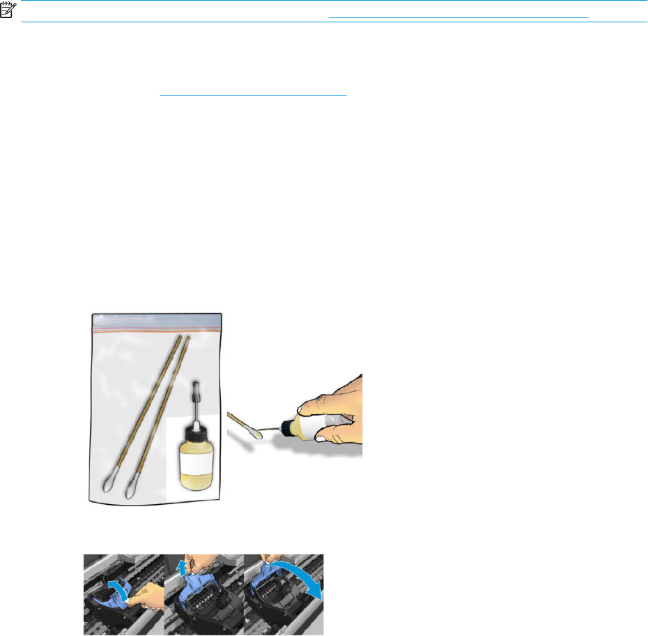
Problems during insertion
At installation
NOTE: To better understand the start up process, see HP 727 Printhead Start-up process on page 28.
Prerequisites: Before starting any troubleshooting, do the following:
1. Ensure the latest rmware is installed in the printer. If you need to update the rmware, download the
latest version from www.hp.com/go/T1500/software.
2. Download the Service plot (this helps to check for error codes and ink levels.
3. Make sure there is enough ink to start up the printhead (40cc for matte black (mK) and 30cc for other inks;
for a tubes purge - 60cc for each color). Ink levels can be checked in the service plot. If in doubt, use 130ml
cartridges.
4. Ensure that septum is gently moisturized (see below)
The tube connectors can be lubricated by moistening with water to help with the insertion of the printhead.
This can be done as follows:
a. Moisten a soft cotton bud with Water or PEG.
b. Open the carriage latch completely.
ENWW Ink supply problems 71

c. Use the wet cotton bud to moisten the septum.
d. Close latch. If necessary, push against the rear side of the carriage to ensure it is properly closed.
The carriage latch is not closed properly
The carriage appears to be closed, but the blue latch sticks up a little and does not stay at.
How to check:
▲Ensure that:
a. The carriage latch is properly engaged.
72 Chapter 2 Troubleshooting ENWW
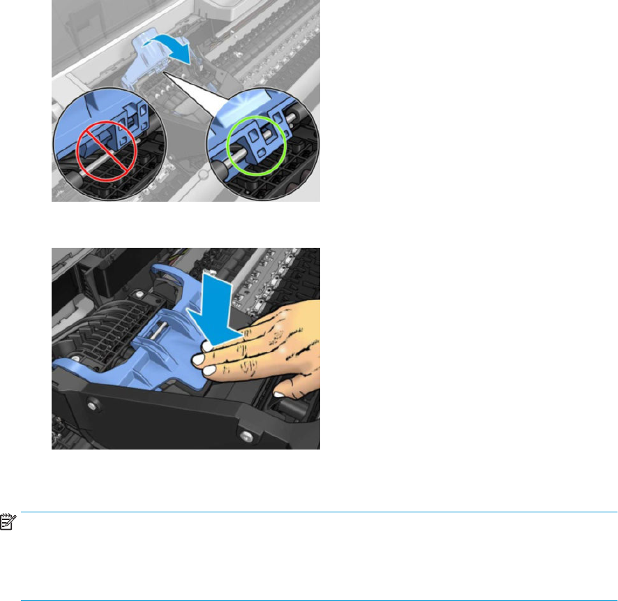
b. The latch is completely down.
If these two conditions are not met, printhead installation may fail and/or some tubes may not be lled
with ink.
NOTE: If the carriage is open, it will be detected by the printer and the customer will be asked to try to
close it again. However, if the carriage is not closed and the printer is powered o, there is a risk that, after
booting up, the printer will raise service system error 86:01. In this case, turn the printer o again, close the
carriage (removing the printhead, if necessary), and then move the printhead to the Service Station. Finally
boot up the printer again.
Root Cause
Incorrect printhead insertion can cause errors because of insucient lubrication or the latch not engaging
properly.
Corrective actions:
1. Perform Prerequisites (Firmware upgrade, moisturize septums).
2. Check that you have the correct type of printhead (model number).
3. Check that the printhead is correctly oriented.
4. Check that you have correctly closed and latched the printhead cover.
ENWW Ink supply problems 73
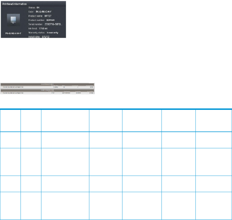
The front panel display recommends reseating the printhead after insertion and no tubes start to ll (tubes are empty)
The printer brings the printhead to the Service Station and rejects it immediately.
1. Perform Prerequisites (Firmware upgrade, moisturize septums).
2. Send/Bring a set of ink supplies plus PHA.
3. Check Printhead errors:
How to check:
When a reseat message appears, the printer will show a printhead error on the Front Panel.
The printer has not yet started to pump ink into the tubes.
Check the Printhead error code
●On the Front Panel check the Printhead “status”:
Go to Main Menu — Printhead — Printhead information.
●From EWS:
Generate the Service plot. Go to the Embedded Web Server: Support tab -> Service support -> Printer
information. This will open a new page. Select the All pages tab. Download this page or print it to a
PDF le.
Printhead error related to RESEAT:
Status
code
(dec)
Status
code
(hex) Status name
User reported
status
Description on
printer HW Test Troubleshooting
0 0x0 WORKING OK The pen is working
properly
All -
2 0x2 FAILS_CONTINUITY RESEAT Pen ID
programming
and pen
continuity
Trailing cable/
PSU/ E-box
4 0x4 SHUTDOWN – Not used NA Trailing cable/
PSU/ E-box
32 0x20 TEMP_EXTREMELY_LO
W
RESEAT The temperature
of the pen is below
the normal
margins
Thermal
runtime tests
PHA Replace
74 Chapter 2 Troubleshooting ENWW

Status
code
(dec)
Status
code
(hex) Status name
User reported
status
Description on
printer HW Test Troubleshooting
128 0x80 TEMP_TOO_LOW RESEAT The temperature
of the pen is below
the normal
margins
Thermal
runtime tests
PHA Replace
8192 0x2000 CSDATA_NOT_RESPON
DING
RESEAT The CSDATA
communication
fails
Pen ID
programming
Trailing/PHA
16384 0x4000 CSDATA_TRANSMIT_ER
ROR
RESEAT The CSDATA
communication is
erroneous
Every pen
communication
Trailing/PHA
4. If the printhead shows Reseat error code (0x00002, 0x02000, 0x04000...)
Root Cause
●If the printer rejects the printhead before even trying to initiate tube purging, it can indicate that the
printer does not recognize the printhead. This may also cause a 0x00002 printhead Error Code to be
shown on the Front Panel.
●The printer is not able to communicate with the printhead.
●Other issues.
Corrective action
●Reseat the same printhead and try again. Follow Front Panel instructions. Do not stop the servicing
routines, allow the printhead to be initialized.
●If it fails replace it with a new PHA and follow Front Panel instructions.
●Try 2 times more with the new PHA.
●If the reseat message continues to appear, check the carriage PCA using the Carriage test in the
diagnostic menu. Replace carriage PCA if needed.
5. If there is no Printhead error shown on the Front Panel or EWS
Root Cause
●Unknown.
Corrective action
●Reseat the same printhead and try again. Follow Front Panel instructions.
After this process it may end on a PH reseat with a PHA error (see step 4 inCheck the Printhead error
code on page 74) or in a Printhead replacement (see The front panel display shows “PH replacement
not complete” on page 75).
The front panel display shows “PH replacement not complete”
The printhead is rejected and some ink tubes are not lled: Yellow and Matte Black are missing, or Cyan,
Magenta, Gray, and Photo Black are missing.
1. Perform Prerequisites (Firmware upgrade, moisturize septums).
ENWW Ink supply problems 75
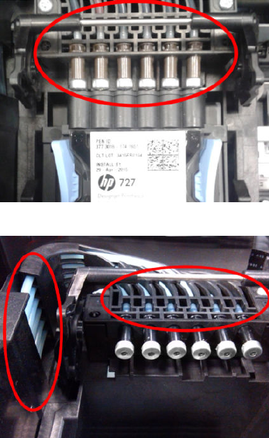
2. For Printers prior to May 2014 (for T3500 go to 3.3).
Visually check if there are empty tubes:
a. Open the carriage.
b. Check the end of the tubes. They should appear as shown in the picture below. The rest of the ink
circuit can be checked for bubbles and ink. When the tubes are empty, they will have a bluish color.
When lled, the tubes will look darker and the yellow channel will have a slight magenta color (due to
the combination of ink color and tube color).
Filled tubes:
Empty tubes:
Root Cause
–There are two primer channels. Yellow and Matte Black share one primer channel. Cyan,
Magenta, Gray, and Photo Black share the other primer channel. If one primer fails, one of the
groups might not get lled.
–There are 2 Ink Supply Stations, If the missing colors are grouped as they are in the Ink Supply
Station, this issue can be related to that part of the printer.
Corrective action
–Run the primer test to check if the primer is working. If it fails, replace the primer.
–Run the “Ink Delivery System diagnostic” to check the status of the Ink Supply Station . If it fails,
replace the corresponding ISS.
–Also, ensure that the ink tube connectors are properly lubricated.
76 Chapter 2 Troubleshooting ENWW

–Run a tube purge to ll all the tubes, including the missing color.
–To purge the tubes, rst remove all supplies (ink and printhead). Then run “Purge tubes” from
the service utilities. Re-insert the inks and printhead, as requested.
NOTE: If a cartridge is inserted and the ink tube is not lled, the printer can potentially mark the
cartridge as “Out Of Ink”. To prevent this from happening, do not install cartridges when some tubes
are empty.
3. For Printers after May 2014 (rmware MRY_02_00_05.6 and later)
In then rmware of those printers, new error codes have been included to simplify diagnosticability of PHA
replacement root cause: Filling SE codes (looking at those SE in the service plot avoids the need to visually
check the ink tubes).
a. Generate the Service plot since the SE93.x.n:10 are not show in the front panel. Go to the Embedded
Web Server: Support tab -> Service support -> Printer information. This will open a new page. Select
the All pages tab. Download this page or print it to a PDF le.
SE 93.0.n:10 During the tube lling, the rst check of ink pressure for color n failed. If no SE 93.2.n:10
appears, it means that the issue was xed after the customer reseated the printhead.
SE 93.2.n:10 After reseating the printhead, the second check of ink pressure for color n failed. This
means that color n in the printhead may not be lled with ink or that the ink tube is leaking.
SE 93.1.n:10 During the tube lling, the rst check of temperature for color n during the printhead
spit test failed. If no SE 93.3.n:10 appears, it means that the issue was xed after the customer
reseated the printhead.
SE 93.3.n:10 During the tube lling and after reseating the printhead, the second check of
temperature for color n during the printhead spit test failed. This means that color n in the printhead
is not lled with ink.
n indicates the color at fault:
–n=0 stands for photo black
–n=1 stands for gray
–n=2 stands for matte black
–n=3 stands for cyan
–n=4 stands for magenta
–n=5 stands for yellow.
b. Service plot shows the following SE:
–SE 93.1.0:10
–SE 93.1.1:10
–SE 93.1.3:10
–SE 93.1.4:10
–SE 93.3.0:10
–SE 93.3.1:10
ENWW Ink supply problems 77
–SE 93.3.3:10
–SE 93.3.4:10
Root Cause
–Upper primer than manages 4 ink tubes( Cyan/Magenta/Gray/Photo black)is failing, therefore,
those tubes are not completely lled.
Corrective action
–Replace upper primer.
–Run the “Ink Delivery System diagnostic” to check the status of the Ink Supply Station . If it fails,
replace the corresponding ISS.
–Also, ensure that the ink tube connectors are properly lubricated.
–Run a tube purge to ll all the tubes, including the missing color.
–To purge the tubes, rst remove all supplies (ink and printhead). Then run “Purge tubes” from
the service utilities. Re-insert the inks and printhead, as requested.
c. Service plot shows the following SE:
–SE 93.1.2:10
–SE 93.1.5:10
–SE 93.3.2:10
–SE 93.3.5:10
Root Cause
–Lower primer than manages 2 ink tubes (Yellow and Matte Black) is failing, therefore, those
tubes are not completely lled.
Corrective action
–Replace lower primer.
–Run the “Ink Delivery System diagnostic” to check the status of the Ink Supply Station . If it fails,
replace the corresponding ISS.
–Also, ensure that the ink tube connectors are properly lubricated.
–Run a tube purge to ll all the tubes.
–To purge the tubes, rst remove all supplies (ink and printhead). Then run “Purge tubes” from
the service utilities. Re-insert the inks and printhead, as requested.
d. Service plot shows the following SE:
–SE 93.1.0:10
–SE 93.1.1:10
–SE 93.1.2:10
–SE 93.3.0:10
78 Chapter 2 Troubleshooting ENWW
–SE 93.3.1:10
–SE 93.3.2:10
Root Cause
–Service Station Side Ink Supply Station than manages 3 ink tubes (Gray/Photo black /Matte
black) is failing, therefore, those tubes are not completely lled.
Corrective action
–Replace Service Station Side Ink supply Station
–Also, ensure that the ink tube connectors are properly lubricated.
–Run a tube purge to ll all the tubes.
To purge the tubes, rst remove all supplies (ink and printhead). Then run “Purge tubes” from
the service utilities. Re-insert the inks and printhead, as requested.
e. Service plot shows the following SE:
–SE 93.1.3:10
–SE 93.1.4:10
–SE 93.1.5:10
–SE 93.3.3:10
–SE 93.3.4:10
–SE 93.3.5:10
Root Cause
–Front Panel Side Ink Supply Station than manages 3 ink tubes(Cyan/Magenta/Yellow)is failing,
therefore, those tubes are not completely lled.
Corrective action
–Replace Front Panel Side Ink supply Station
–Also, ensure that the ink tube connectors are properly lubricated.
–Run a tube purge to ll all the tubes.
To purge the tubes, rst remove all supplies (ink and printhead). Then run “Purge tubes” from
the service utilities. Re-insert the inks and printhead, as requested.
f. Service plot shows one or several 93.x.n:10 SE:
–If multiple colors are missing, there will be both a SE 93.1.n:10 and SE 93.3.n:10 for each
missing color.
–If only a SE 93.1.n:10 appears, it means that the color failed to be lled during the rst attempt,
but the printer auto recovery was able to fully ll the printhead.
Root Cause
–Any of the aforementioned root causes may apply.
ENWW Ink supply problems 79

Corrective action
–Test the primer and Ink Supply Station. Ensure the ink tube connectors are properly lubricated.
–Run a tube purge to ll all the tubes.
To purge the tubes, rst remove all supplies (ink and printhead). Then run “Purge tubes” from
the service utilities. Re-insert the inks and printhead, as requested.
NOTE: If a cartridge is inserted and the ink tube is not lled, the printer can potentially mark the cartridge
as “Out Of Ink”. To prevent this from happening, do not install cartridges when some tubes are empty.
The printer rebooted during the start-up; printhead initialization took a long time and was then canceled
Root cause
●Printhead issue.
●Incorrect error message from drop detection that causes the printer to carry out additional servicing
routines.
●Other issues.
Corrective action
●Do not stop the servicing routines, allow the printhead to be initialized.
●If, after the start-up, the image quality is poor, carry out the usual image quality troubleshooting.
●If at the moment of interruption (System Error or user intervention) the tubes were already lled, try to re-
install the printhead.
●If at the moment of interruption (System Error or user intervention) the tubes weren’t fully loaded yet, try
to launch a Tube Purge from the Service Menu.
During Usage
During normal usage, any Printhead reseat or replacement should imply sending a new PHA.
The printhead shows an Error Code 0x00010 or 0x00040
The printhead shows an Error Code 0x00010 or 0x00040.
Root Cause
The nozzle area is overheating. This can be due to air present in the nozzle area of the printhead.
Corrective action
Check that the ink tubes are lled and have no air bubbles. Run manual printhead cleaning to try to restore
the printhead. Ultimately, replace the printhead if needed.
All ink tubes are lled, but the printer requests a random printhead reseat
Root Cause
To analyze the root cause, check the printhead Error Code in the table at the end of this document.
Corrective action
80 Chapter 2 Troubleshooting ENWW

The printhead reseat issue can be solved by simply removing and reinstalling the printhead. If, after the
reseat, the error message continues, try a new printhead. If the reseat message continues to appear, check
the carriage PCA using the Carriage test in the diagnostic menu.
During printer installation troubleshooting, the printer asks if the printhead to be used is “New” or “Reused”
Root Cause
Depending on the situation, when trying to replace the printhead with a new one, the printer can ask if the
printhead that is going to be used is “New” or “Reused”. For instance, this can happen when the ink tubes
are lled, but the printhead installation fails during the servicing routines.
Corrective action
If doing a reseat of the old printhead, the “Reused” option should be selected. The “New” option should
only be selected if the printhead that is going to be used needs to be lled with ink. When “New” is
selected, the printer will check if there is enough ink to run the new printhead installation. If there is not
enough ink, the printer will only carry out the servicing routines to prepare the printhead.
Clean the printhead
As long as the printer is kept turned on, automatic cleaning is performed periodically. This ensures there is fresh
ink in the nozzles and prevents nozzle clogs, thus preserving print quality. If you have print quality problems,
please see Print-quality problems on page 84 before proceeding.
To clean the printhead, go to the front panel and press , then , then Image Quality Maintenance >
Clean printhead, and select the color group including the color that needs cleaning (Clean all, Clean MK-Y, Clean
C-M-PK-G).
Align the printhead
Precise printhead alignment is essential for accurate colors, smooth color transitions, and sharp edges in
graphical elements. Your printer has an automatic printhead alignment process which runs whenever the
printhead has been accessed or replaced.
You may need to align the printhead after a paper jam or if you are experiencing print-quality problems.
1. Load the paper you wish to use. You can use a roll or a cut sheet; plain white paper is recommended.
CAUTION: Do not use transparent or semi-transparent paper to align the printhead.
2. Ensure that the window is closed, as a strong light source near the printer during printhead realignment
can aect alignment.
3. From the front panel, press , then Image Quality Maintenance > Align printhead.
NOTE: Printhead alignment can also be started from the Embedded Web Server (Support > Print Quality
Troubleshooting), or from the HP Utility (Windows: Support > Print Quality Troubleshooting; Mac OS X:
Information and Print Quality > Align).
4. If the loaded paper is satisfactory, the printer runs the realignment and prints a realignment pattern.
5. The process takes about ve minutes. Wait until the front panel display shows the process complete before
using the printer.
ENWW Ink supply problems 81
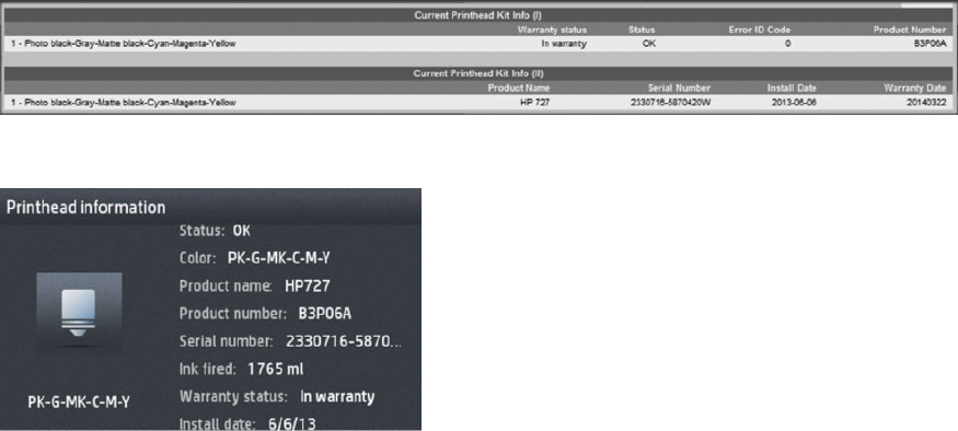
If the printer cannot complete the printhead alignment successfully, you may be asked to clean the printhead
and try again.
Printhead status messages
These are the possible printhead status messages:
●OK: The printhead is working normally, with no known problems
●Missing: There is no printhead present, or it is not correctly installed in the printer.
●Reseat: You are recommended to remove the printhead and then reinsert it. If that fails, clean the electrical
connections. If that fails, replace the printhead with a new one.
●Replace: The printhead is failing. Replace the printhead with a working one.
●Replacement incomplete: The printhead replacement process has not completed successfully; re-launch
the replacement process and let it nish completely.
●Remove: The printhead is not a suitable type for use in printing.
●Non-HP ink: Ink from a used, relled, or counterfeit ink cartridge has passed through the printhead. See the
limited warranty document provided with your printer for details of the warranty implications.
Printhead 727 Error codes
How to check the printhead error code:
●Generate the Service plot. Go to the Embedded Web Server: Support tab > Service support > Printer
information. This will open a new page. Select the All pages tab. Download this page or print it to a PDF le.
●Alternatively, check the printhead “Status” in the Front Panel.
Printhead 727 error codes:
The following table lists the potential error codes reported by the printer:
82 Chapter 2 Troubleshooting ENWW

Status / Failure
mode
Action
reported to
user
Service
Support /
Printer
Information
Code by
EWS
Printhead
Information
by Control
Panel Description
WORKING OK 0 0x00000 The pen is working properly
FAILS_LOGICAL_V RESEAT 1 0x00001 Under-voltage, over-voltage or ink shortage detected in Vcc (5V)
FAILS_CONTINUIT
Y
RESEAT 2 0x00002 Failed pen ID programming or pen continuity tests
SHUTDOWN REPLACE 4 0x00004 CsData fault, printhead clock or temperature error
FAILS_VPP RESEAT 8 0x00008 Under-voltage, over-voltage, leakage or ink shortage detected in Vpp or
VppLogic
TEMP_EXTREMELY
_HIGH
REPLACE 16 0x00010 The temperature of the pen is beyond maximum margin
TEMP_EXTREMELY
_LOW
REPLACE 32 0x00020 The temperature of the pen is under minimum margin
TEMP_TOO_HIGH RESEAT 64 0x00040 The temperature of the pen has been above the normal margins for too
long
TEMP_TOO_LOW RESEAT 128 0x00080 The temperature of the pen has been below the normal margins for too
long
BAD_ACUMEN_IN
FO
REPLACE 256 0x00100 Parity error on printhead bits
NO_PEN MISSING 512 0x00200 There is no pen detected
BAD_ACUMEN_AC
CESS
RESEAT 1024 0x00400 Error while reading or writing printhead bits
WRONG_MODEL REMOVE 2048 0x00800 The model inserted is not the model required by the printer
MISMATCH REMOVE 4096 0x01000 The color or the printhead version is not in the required slot
CSDATA_NOT_RES
PONDING
RESEAT 8192 0x02000 The CSDATA communication failed
CSDATA_TRANSMI
T_ERROR
RESEAT 16384 0x04000 The CSDATA communication failed
EXPIRED_WARRA
NTY
— 524288 0x80000 The printhead is ok but failed the warranty validation
ENWW Ink supply problems 83

Print-quality problems
●General advice
●Print-quality troubleshooting wizard
●Recalibrate the paper advance
●Horizontal lines across the image (banding)
●Lines are too thick, too thin or missing
●Lines appear stepped or jagged
●Lines print double or in the wrong colors
●Lines are discontinuous
●Lines are blurred
●Line lengths are inaccurate
●The whole image is blurry or grainy
●The paper is not at
●The print is scued or scratched
●Ink marks on the paper
●Black ink comes o when you touch the print
●Edges of objects are stepped or not sharp
●Edges of objects are darker than expected
●Horizontal lines at the end of a cut sheet print
●Vertical bands of dierent colors
●White spots on the print
●Colors are inaccurate
●Colors are fading
●The image is incomplete (clipped at the bottom)
●The image is clipped
●Some objects are missing from the printed image
●A PDF le is clipped or objects are missing
●Avoiding the stretching of printouts in Solidworks and HPGL2 drivers
●The Image Diagnostics Print
●Product Limitations
●If you still have a problem
84 Chapter 2 Troubleshooting ENWW

General advice
When you have any print-quality problem:
●To achieve the best performance from your printer, use only genuine manufacturer's supplies and
accessories, whose reliability and performance have been thoroughly tested to give trouble-free
performance and best-quality prints. For details of recommended papers, see users guide.
●Make sure that the paper type selected in the front panel is the same as the paper type loaded into the
printer (see users guide). At the same time, check that the paper type has been calibrated. Also make sure
that the paper type selected in your software is the same as the paper type loaded into the printer.
CAUTION: If you have the wrong paper type selected, you could experience poor print quality and
incorrect colors, and perhaps even damage to the printhead.
●Check that you are using the most appropriate print-quality settings for your purposes (see users guide).
You are likely to see lower print quality if you have moved the print-quality slider to the 'Speed' end of the
scale, or set the custom quality level to Fast.
●Check that your environmental conditions (temperature, humidity) are in the recommended range. See
users guide.
●Check that your ink cartridges and printhead have not passed their expiration dates: see users guide.
For the latest information, please visit http://www.hp.com/go/T920/support or http://www.hp.com/go/T1500/
support.
Print-quality troubleshooting wizard
The print-quality troubleshooting wizard can help with the following problems:
●Horizontal lines across the image (banding)
●The whole image is blurry or grainy
●Lines are too thick, too thin or missing
●Colors are inaccurate
To start the wizard:
●From the HP Designjet Utility for Windows: Go to the Support tab, and select Print Quality Toolbox.
●From the HP Utility for Mac OS X: Select Print quality troubleshooting in the Support group.
●From the Embedded Web Server: Go to the Support tab, then select Print quality troubleshooting.
●From the front panel: Press , then , then Image quality maintenance.
Alternatively, or if you have other print-quality problems, you can continue reading this chapter.
Recalibrate the paper advance
Accurate paper advance is important to image quality because it is part of controlling the proper placement of
dots on the paper. If the paper is not advanced the proper distance between printhead passes, light or dark
bands appear in the print and image grain may increase.
ENWW Print-quality problems 85
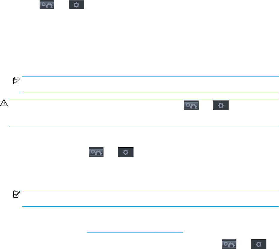
The printer is calibrated to advance correctly with all the papers appearing in the front panel. When you select
the type of loaded paper, the printer adjusts the rate at which to advance the paper while printing. However, if
you are not satised with the default calibration of your paper, you may need to recalibrate the rate at which the
paper advances. See users guide for steps to determine if paper advance calibration will solve your issue.
You can check the paper advance calibration status of the currently loaded paper at any time from the front
panel. Press , then , then Image quality maintenance > Calibration status. The status may be one of
the following.
●DEFAULT: This status appears when loading any paper that has not been calibrated. HP papers in the Front
Panel have been optimized by default and unless you experience image quality problems in your printed
image such as banding or graininess it is not recommended to recalibrate the paper advance.
●OK: This status indicates that the loaded paper has been calibrated before. However you may need to
repeat the calibration if you experience image quality problems such as banding or graininess in your
printed image.
NOTE: Whenever you update the printer’s rmware, the paper advance calibration values are reset to
factory default, see users guide.
CAUTION: Transparent papers and lms must be calibrated by pressing , then , then Image quality
maintenance > Paper advance calibration > Adjust paper advance, from step four in Recalibrating the paper
advance procedure.
Recalibrating the paper advance procedure
1. From the front panel, press , then , then Image quality maintenance > Paper advance
calibration > Calibrate paper advance. The printer automatically recalibrates the paper advance and prints a
paper advance calibration image, which you can send to stacker or basket.
2. Wait until the front panel displays the status screen, then reprint your print.
NOTE: The recalibration procedure takes a few minutes. Do not worry about the paper advance
calibration image. The front-panel display shows any errors in the process.
If you are satised with your print continue using this calibration for your paper type. If you see
improvement in your print, continue with step three. If you are dissatised with the recalibration, return to
the default calibration, see Return to default calibration on page 87.
3. If you would like to ne-tune the calibration or are using a transparent paper, press , then ,
then Image quality maintenance > Paper advance calibration > Adjust paper advance.
86 Chapter 2 Troubleshooting ENWW

4. Select the percentage of change from –100% to +100%. To correct light banding, decrease the percentage.
To correct dark banding, increase the percentage.
5. Press OK on the front panel, to save the value.
6. Wait until the front panel displays the status screen and reprint your print.
Return to default calibration
Returning to the default calibration sets all the corrections made by the paper advance calibration to zero. To
return to the default paper advance calibration value, you must reset the calibration.
1. From the front panel, press , then , then Image quality maintenance > Paper advance
calibration > Reset paper advance.
2. Wait until the front panel displays the operation has completed successfully.
Horizontal lines across the image (banding)
If your printed image suers from added horizontal lines as shown (the color may vary):
ENWW Print-quality problems 87

1. Check that the paper type you have loaded corresponds to the paper type selected in the front panel and in
your software. See users guide.
2. Check that you are using appropriate print-quality settings for your purposes (see users guide). In some
cases, you can overcome a print-quality problem merely by selecting a higher print-quality level. For
instance, if you have set the Print Quality slider to Speed, try setting it to Quality. If you change the print-
quality settings, you may wish to reprint your job at this point in case the problem has been solved.
3. Print the Image Diagnostics Print. See The Image Diagnostics Print on page 98.
4. If the printhead is working correctly, go to the front panel and press , then , then Image quality
maintenance > Calibration status to see the paper advance calibration status. If the status is DEFAULT, try
performing paper advance calibration: see Recalibrate the paper advance on page 85.
In case you are using rolls with 3-in core adaptors:
1. Check that the roll core is not damaged.
2. Make sure that the 3-in adaptor is correctly attached to the spindle.
3. Print using Roll 1 for better performance.
4. Print in a higher quality/slower mode.
5. If horizontal banding is only showing in the laterals of the media, check that the 3-in. adaptors are
positioned so that the spring of the black hub and the blue hub are aligned:
If the problem persists despite all the above actions, contact your customer service representative for further
support.
88 Chapter 2 Troubleshooting ENWW
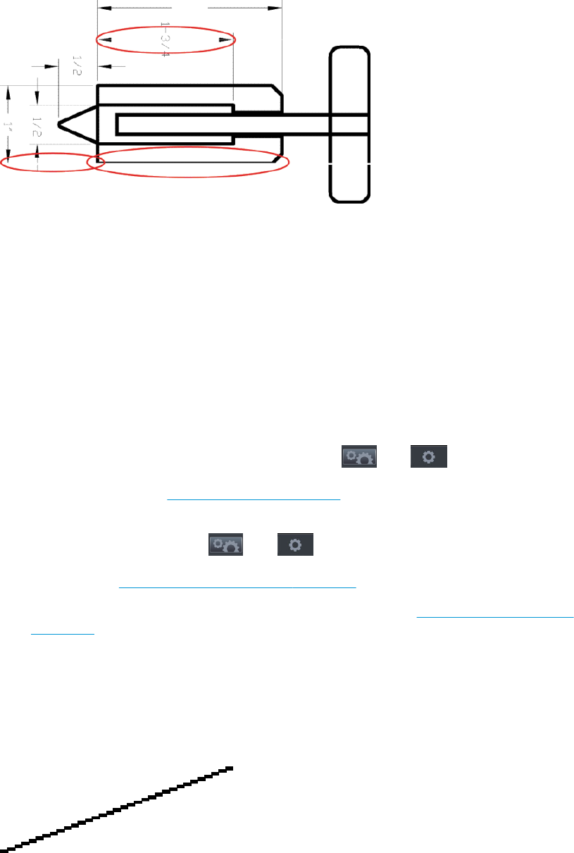
Lines are too thick, too thin or missing
1. Check that the paper type you have loaded corresponds to the paper type selected in the front panel and in
your software. See users guide.
2. Check that you are using appropriate print-quality settings for your purposes (see users guide). If printing
on photo paper, select the custom print-quality options in the driver dialog, and try turning on the
Maximum detail option (if available). You may wish to reprint your job at this point in case the problem has
been solved.
3. If the resolution of your image is greater than the printing resolution, you may notice a loss of line quality. If
you are using the PCL3GUI or the HP-GL/2 driver for Windows, you can nd the Max. Application Resolution
option in the driver dialog's Advanced tab, under Document Options > Printer Features. If you change this
option, you may wish to reprint your job at this point in case the problem has been solved.
4. When printing on uncoated paper in Fast mode, try loading the paper as Bright Bond.
5. If the problem remains, go to the front panel and press , then , then Image quality
maintenance > Align printhead to see the printhead alignment status. If the status is PENDING, you should
align the printhead. See Align the printhead on page 81. After alignment, you may wish to reprint your job
in case the problem has been solved.
6. Go to the front panel and press , then , then Image quality maintenance > Calibration status to
see the paper advance calibration status. If the status is DEFAULT, you should perform paper advance
calibration: see Recalibrate the paper advance on page 85.
7. If lines are too thin or missing, print the Image Diagnostics Print. See The Image Diagnostics Print
on page 98.
If the problem persists despite all the above actions, contact your customer service representative for further
support.
Lines appear stepped or jagged
If lines in your image appear stepped or jagged when printed:
ENWW Print-quality problems 89

1. The problem may be inherent in the image. Try to improve the image with the application you are using to
edit it.
2. Check that you are using appropriate print-quality settings. See users guide.
3. Select the custom print-quality options in the driver dialog, and turn on the Maximum detail option (if
available).
Lines print double or in the wrong colors
This problem can have various visible symptoms:
●Colored lines are printed double, in dierent colors.
●The borders of colored blocks are wrongly colored.
To correct this kind of problem:
1. Align the printhead. See Align the printhead on page 81.
2. Reseat the printhead by removing and then reinserting it. See users guide.
Lines are discontinuous
If your lines are broken in the following way:
1. Check that you are using appropriate print-quality settings. See users guide.
2. When printing on uncoated paper in Fast mode, try loading the paper as Bright Bond.
90 Chapter 2 Troubleshooting ENWW

3. Align the printhead. See Align the printhead on page 81.
4. Reseat the printhead by removing and then reinserting it. See users guide.
Lines are blurred
Humidity can cause ink to soak into the paper, making the lines blurred and fuzzy. Try the following:
1. Check that your environmental conditions (temperature, humidity) are suitable for high-quality printing.
See users guide.
2. Check that the paper type selected in the front panel is the same as the paper type you are using. See
users guide.
3. Try changing to a heavier paper type, such as HP Heavyweight Coated Paper or HP Super Heavyweight Plus
Matte Paper.
4. Select a paper type that is slightly thinner than the paper you have loaded; this will persuade the printer to
use less ink. Here are some example paper types in ascending order of thickness: Plain Paper, Coated
Paper, Heavyweight Coated Paper, Super Heavyweight Plus Matte Paper.
5. If you are using photo paper, try changing to a dierent type of photo paper.
6. Align the printhead. See Align the printhead on page 81.
Line lengths are inaccurate
If you have measured your printed lines and nd that the lengths are not suciently accurate for your purposes,
you can try to improve line length accuracy in the following ways.
1. Print on HP Matte Film, for which your printer's line length accuracy is specied. See users guide.
Polyester lm is about ten times more dimensionally stable than paper. However, using lm that is thinner
or thicker than HP Matte Film will reduce line length accuracy.
2. Set the Print Quality slider to Quality.
3. Maintain the room at a steady temperature between 10 and 30°C (50 and 86°F).
4. Load the roll of lm and let it rest for ve minutes before printing.
5. If you are still not satised, try recalibrating the paper advance. See Recalibrate the paper advance
on page 85.
ENWW Print-quality problems 91
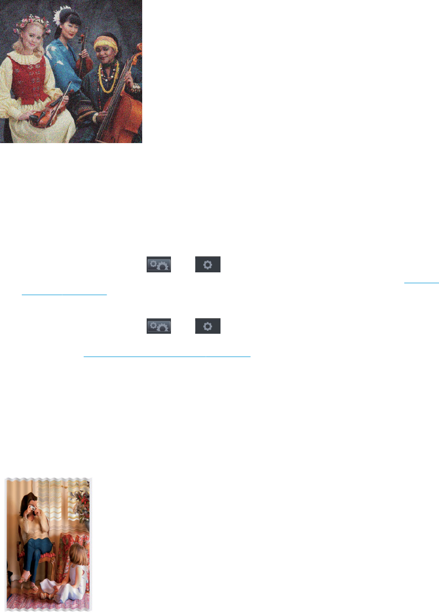
The whole image is blurry or grainy
1. Check that the paper type you have loaded corresponds to the paper type selected in the front panel and in
your software. See users guide.
2. Check that you are printing on the correct side of the paper.
3. Check that you are using appropriate print-quality settings (see users guide). In some cases, you can
overcome a print-quality problem merely by selecting a higher print-quality level. For instance, if you have
set the Print Quality slider to Speed, try setting it to Quality. If you change the print-quality settings, you
may wish to reprint your job at this point in case the problem has been solved.
4. Go to the front panel and press , then , then Image quality maintenance > Calibration status to
see the printhead alignment status. If the status is PENDING, you should align the printhead. See Align the
printhead on page 81. After alignment, you may wish to reprint your job in case the problem has been
solved.
5. Go to the front panel and press , then , then Image quality maintenance > Calibration status to
see the paper advance calibration status. If the status is DEFAULT, you should perform paper advance
calibration: see Recalibrate the paper advance on page 85.
If the problem persists despite all the above actions, contact your customer service representative for further
support.
The paper is not at
If the paper does not lie at when it comes out of the printer, but has shallow waves in it, you are likely to see
defects in the printed image, such as vertical stripes. This can happen when you use thin paper that becomes
saturated with ink.
92 Chapter 2 Troubleshooting ENWW

1. Check that the paper type you have loaded corresponds to the paper type selected in the front panel and in
your software. See users guide.
2. Try changing to a thicker paper type, such as HP Heavyweight Coated Paper or HP Super Heavyweight Plus
Matte Paper.
3. Select a paper type that is slightly thinner than the paper you have loaded; this will persuade the printer to
use less ink. Here are some example paper types in ascending order of thickness: Plain Paper, Coated
Paper, Heavyweight Coated Paper, Super Heavyweight Plus Matte Paper.
4. If you see horizontal stripes, try printing the same job rotated; this sometimes reduces the visibility of the
stripes.
The print is scued or scratched
The black ink pigment can be scued or scratched when touched by a nger, a pen or some other object. This is
particularly noticeable on coated paper.
Photo paper may be extremely sensitive to the basket or to anything else that it contacts soon after printing,
depending on the amount of ink used and the environmental conditions at the time of printing.
To reduce the risk of scus and scratches:
●Handle prints carefully.
●Catch your prints as they are cut from the roll and do not let them fall into the basket. Alternatively, leave a
sheet of paper in the basket so that freshly printed sheets do not make direct contact with the basket.
Ink marks on the paper
This problem can occur for several dierent reasons.
Horizontal smears on the front of the paper
When a lot of ink is used on a paper-based material, the paper absorbs the ink quickly and expands. If the paper
is sti and curled, near the end of the roll the leading edge of the paper may rise slightly in the print area. As the
printhead moves over the paper, it may come into contact with the paper and smear the printed image.
Whenever you notice this problem, cancel the printing job immediately. Press on the front panel and also
cancel the job from your computer application. Soaked paper can damage the printhead.
Try the following suggestions to avoid this problem:
1. Increase the margins by relocating the image to the center of the page, either with your software or with
the front panel’s Move Paper option (see users guide). To prevent such smears most eectively, the
distance from the image to the leading edge of the paper should be at least 20 mm (0.8 in).
2. Select a faster print mode: change from Best to Normal, or from Normal to Fast mode.
ENWW Print-quality problems 93

Other smears on the paper
The following suggestions may be used for all kinds of smears, including those on the front of the paper:
1. Check that the paper type you have loaded corresponds to the paper type selected in the front panel and in
your software. See users guide.
2. Use a recommended paper type (see users guide) and the correct print settings.
3. If using sheet paper, try rotating the sheet 90 degrees. The orientation of the paper bers may aect
performance.
4. Try changing to a thicker paper type, such as HP Heavyweight Coated Paper or HP Super Heavyweight Plus
Matte Paper.
5. Select a paper type that is slightly thinner than the paper you have loaded; this will persuade the printer to
use less ink. Here are some example paper types in ascending order of thickness: Plain Paper, Coated
Paper, Heavyweight Coated Paper, Super Heavyweight Plus Matte Paper.
Black ink comes o when you touch the print
This problem may be caused by printing with matte black ink on photo paper. The printer will not use matte black
ink if it knows that the paper will not retain it. To be sure of avoiding matte black ink, you can select Photo Gloss
Paper as the paper type (in the Photo Paper category).
Edges of objects are stepped or not sharp
If edges of objects or lines appear to be poorly dened or lighter in density, and you have already set the print-
quality slider to Quality in the driver dialog, select the custom print-quality options, and try setting the quality
level to Normal. See users guide.
Edges of objects are darker than expected
94 Chapter 2 Troubleshooting ENWW

If edges of objects seem darker than expected, and you have already set the print-quality slider to Quality in the
driver dialog, select the custom print-quality options, and try setting the quality level to Normal. See users guide.
Horizontal lines at the end of a cut sheet print
This type of defect aects only the end of a print, within approximately 30 mm of the trailing edge of the paper.
You may see some very thin horizontal lines across the print.
To avoid this problem:
1. Print the Image Diagnostics Print. See The Image Diagnostics Print on page 98.
2. Consider printing with roll paper.
3. Consider using larger margins around your image.
Vertical bands of dierent colors
If your print has vertical bands of dierent colors along it:
1. Try using higher print-quality settings (see users guide). For instance, if you have set the Print Quality slider
to Speed, try setting it to Quality.
2. Try using thicker paper, choosing from the recommended paper types such as HP Heavyweight Coated
Paper and HP Super Heavyweight Paper. See users guide.
White spots on the print
You may notice white spots on the print. This is probably due to paper bers, dust or loose coating material. To
avoid this problem:
1. Try cleaning the paper manually with a brush before printing, to remove any loose bers or particles.
2. Always keep the cover of your printer closed.
3. Protect your paper rolls and sheets by storing them in bags or boxes.
Colors are inaccurate
If the colors of your print do not match your expectations, try the following:
1. Check that the paper type you have loaded corresponds to the paper type selected in the front panel and in
your software. See users guide. Also, press , then , then Image quality maintenance >
Calibration status to check the color calibration status. If the status is PENDING or OBSOLETE, you should
ENWW Print-quality problems 95

perform color calibration: see users guide. If you have made any changes, you may wish to reprint your job
in case the problem has been solved.
2. Check that you are printing on the correct side of the paper.
3. Check that you are using appropriate print-quality settings (see users guide). If you have selected the
Speed or Fast options, you may not get the most accurate colors. If you change the print-quality settings,
you may wish to reprint your job at this point in case the problem has been solved.
4. If you are using Application Color Management, check that the color prole you are using corresponds to
the selected paper type and print-quality settings. If you have doubts about which color settings to use,
see users guide.
5. If the problem consists of color dierences between your print and your monitor, please follow the
instructions in the “How to calibrate your monitor” section of the HP Color Center. At this point, you may
wish to reprint your job in case the problem has been solved.
6. Print the Image Diagnostics Print. See The Image Diagnostics Print on page 98.
7. Try using the color adjustment options to produce the colors you want. See users guide.
If the problem persists despite all the above actions, contact your customer service representative for further
support.
Color accuracy using EPS or PDF images in page layout applications
Page layout applications such as Adobe InDesign and QuarkXPress do not support color management of EPS,
PDF or grayscale les.
If you have to use such les, try to ensure that the EPS, PDF or grayscale images are already in the same color
space that you intend to use later on in Adobe InDesign or QuarkXPress. For instance, if your nal goal is to print
the job in a press that follows the SWOP standard, convert the image into SWOP when you create it.
Colors are fading
If you print on instant-dry photo paper, your prints will fade rapidly. If you plan to display the prints for more than
two weeks, you should laminate them to achieve longer life.
Prints on swellable coated papers will fade much less rapidly. However, lamination will increase the life of prints
(depending on the type of lamination) with all paper types. For more information, consult your laminate provider.
The image is incomplete (clipped at the bottom)
●Did you press before all the data were received by the printer? If so, you have ended the data
transmission and will have to print the page again.
●There may be a communications problem between your computer and the printer. Check your network
cable.
●Check to make sure that your software settings are correct for your current page size (for example, long-
axis prints).
●If you are using network software, make sure it has not timed out.
96 Chapter 2 Troubleshooting ENWW

The image is clipped
Clipping normally indicates a discrepancy between the actual printable area on the loaded paper and the
printable area as understood by your software. You can often identify this kind of problem before printing by
previewing your print (see users guide).
●Check the actual printable area for the paper size you have loaded.
printable area = paper size – margins
●Check what your software understands to be the printable area (which it may call "printing area" or
"imageable area"). For example, some software applications assume standard printable areas that are
larger than those used in this printer.
●If you have dened a custom page size with very narrow margins, the printer may impose its own minimal
margins, clipping your image slightly. You may want to consider using a larger paper size, or borderless
printing (see users guide).
●If your image contains its own margins, you may be able to print it successfully by using the Clip Contents
by Margins option (see users guide).
●If you are trying to print a very long image on a roll, check that your software is capable of printing an
image of that size.
●You may have asked to rotate the page from portrait to landscape on a paper size that is not wide enough.
●If necessary, reduce the size of the image or document in your software application, so it ts between the
margins.
There is another possible explanation for a clipped image. Some applications, such as Adobe Photoshop, Adobe
Illustrator and CorelDRAW, use an internal 16-bit coordinate system which means that they cannot handle an
image of more than 32,768 pixels.
NOTE: An image 32,768 pixels long would print at a length of 1.39 m (54.61 in) if you select Best or Quality in
the driver, 2.78 m (109.23 in) if you select Fast, Normal or Speed in the driver.
If you try to print an image larger than this from these applications, the bottom of the image may be clipped. To
print the whole image, try these suggestions:
●Try using the PostScript printer driver to print your job, if you have not already tried it.
●The Windows HP-GL/2 driver dialog includes an option called Max. application resolution, which enables
you to print successfully in this situation. You will not normally need to change the default setting, which is
Auto. However, you can nd the option in the Advanced tab, under Document Options > Printer Features.
●Save the le in another format, such as TIFF or EPS, and open it with another application.
●Use a RIP to print the le.
Some objects are missing from the printed image
Large quantities of data may be necessary to print a high-quality large-format print job, and in some specic
workows there may be issues that can lead to some objects missing from the output. Here are some
suggestions to help you to avoid this problem.
●Try using the PostScript printer driver to print your job, if you have not already tried it.
●Select a smaller page size and scale to the desired nal page size in the driver or in the front panel.
ENWW Print-quality problems 97

●Save the le in another format, such as TIFF or EPS, and open it with another application.
●Use a RIP to print the le.
●Reduce the resolution of bitmap images in your application software.
●Select a lower print quality in order to reduce the resolution of the printed image.
NOTE: If you are working under Mac OS X, not all of these options are available.
These options are suggested for troubleshooting purposes and may adversely aect the nal output quality or
the time necessary to generate the print job. Therefore, they should be cancelled if they do not help to solve the
problem.
A PDF le is clipped or objects are missing
In older versions of Adobe Acrobat or Adobe Reader, large PDF les could be clipped or lose some objects when
printing with the HP-GL/2 driver at high resolution. In order to avoid such problems, update your Adobe Acrobat
or Adobe Reader software to the latest version. From version 7 onwards, these problems should be solved.
Avoiding the stretching of printouts in Solidworks and HPGL2 drivers
Printing with the High Quality feature enabled can cause printouts to appear stretched; this issue will be solved in
future driver releases.
In the meantime, you can avoid the issue by following these steps.
IMPORTANT: It is critical to follow all steps in order.
1. Enter Driver Properties.
a. Adjust all settings you need to modify from the Driver’s Properties dialog.
b. Click OK and do not re-enter to the Driver’s Properties again.
2. Enter Page Setup.
a. Adjust all settings you need to modify from the Page Setup dialog. If needed, select the High Quality
option.
b. Click OK to close the dialog.
3. Click the Print button in order to print the job with the selected settings.
NOTE: After closing the Page Setup dialog, do not enter the Driver’s Properties again; it will cause the printout
to stretch.
The Image Diagnostics Print
See Diagnostics Print on page 207.
Product Limitations
This Product limitations review document is designed to highlight and communicate the major product
limitations of the HP Designjet T2500/T2530/T3500 Printers. Included are appropriate workarounds (where
possible). It is intended for HP internal use only and is subject to change as and when new information is
available. It should be treated with the utmost condentiality, and should not be reproduced and distributed
98 Chapter 2 Troubleshooting ENWW
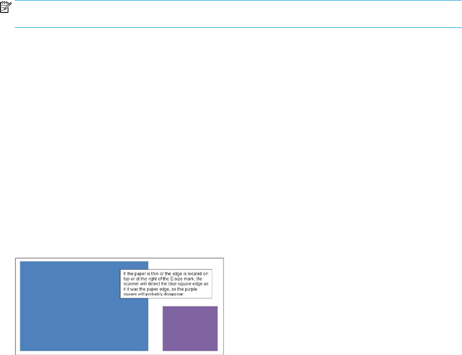
openly. Its purpose is to serve as an informational document for those who come into direct contact with
customers (Sales Force, Marketing Centers, and Technical Support) in order that they can VERBALLY
acknowledge the limitations, explain them, and provide the best possible workaround. The limitations described
here will only aect some users some of the time.
NOTE: For a complete up to date list of printing related Product limitations; please check the T920/T1500
Product Limitations document.
Scanner
Part of the image is lost when scanning thin or semi-transparent paper
Limitation type
Permanent
Symptoms aecting the customer
Clipping on an image when scanning thin or transparent media; the following two reasons explain why:
●The scanner reads content located inside the E-size marks, any image part outside will not be read. If the
paper edge is located outside those marks, it will not be detected either.
●If the paper is too thin, the scanner may not locate the paper edge easily.
In both situations, the scanner can confuse a black line inside the image with the paper edge. If the image prole
is not regular, parts of the image can be lost. Example:
Communication to the customer
There are some workarounds available to minimize this issue:
1. Make sure that the paper edge is located at the left of the E-size mark.
2. Change the job orientation; it could work better for the image type you want to scan.
3. If the paper is too thin, place a piece of white paper below the original when scanning.
4. Use the Scan full width option.
Context
The algorithm to detect the paper edge has improved compared to the T2300, but it still might fail depending on
the image and paper type.
Scan to LAN cannot be congured successfully in IPv6 or IPSec networks
Limitation type
Permanent
ENWW Print-quality problems 99
Symptoms aecting the customer
The issue happens when trying to setup a folder for scanning, and the customer network uses pure IPv6
protocol, or has IPSec protocol congured.
The Embedded Web Server shows an error message when trying to setup the folder saying that the computer
specied as a server cannot be found. It is not possible to set up, and use scan to folder in this environment.
Communication to the customer
In order to use scan to folder at least a mixed IPv4/IPv6 network is required. In case of IPSec, the scan to folder
will never work if the network is using IPSec policies. We recommend in this case using the Scan to USB option.
Context
Same problem happens in the T2300.
Firmware
Sending multiple images using PCL3GUi driver in Mac with Nesting ON might lead to printer system error 79:04
Limitation Type
Temporary
Symptoms aecting the customer
When sending two or more images to the printer using the PCL3GUi driver from Mac, if the printer has nesting
activated and the images contain white areas, the printer is not able to process correctly, and shows system
error 79:04. Details of the system error are:
●SE: 79:04
●File: vpmBe.c
●Line 2024
Communication to the customer
As a temporary workaround, in case of system error, switch nesting o to print these les. A new driver is being
developed that solves this problem.
Context
This problem is specic to this driver version, other printers or drivers do not show it.
Driver
When printing a multi-page le, time to start printing might be long
Limitation type
Temporary
Symptoms aecting the customer
After installing the Windows driver, the Page Order setting is set by default to First page on top. By doing this,
the printer has to process all the pages before starting to print, in order to start printing with the last page, and
leave the rst page on top of the stacker, so taking longer to process and begin.
100 Chapter 2 Troubleshooting ENWW
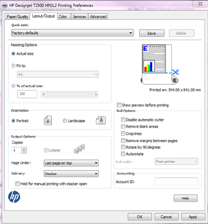
This will be changed in future driver releases, but customers that already installed the driver with the rst
version of the DVD need to change the setting manually to improve performance.
Communication to the customer
To improve the processing time, change the setting to Last page on top.
Context
This problem does not occur in the T920/T1500 because the driver default is already set to Last page on top.
Connectivity
Printer cannot access the Internet after changing the proxy settings
Limitation type
Permanent
Symptoms aecting the customer
After changing the proxy settings in the printer, trying to connect to the Internet may give an error message.
Communication to the customer
In some cases it is required to restart the printer to refresh the Internet settings.
Image Quality
Printouts show dierent colors compared to the T790/T1300/T2300
Limitation type
Temporary
Symptoms aecting the customer
If a customer replaces a T2300 MFP with a T2500 MFP, they will notice a color change when printing certain
images with certain paper types, and using some setting combinations.
ENWW Print-quality problems 101

Communication to the customer
Colors are dierent in the T2500 due to dierences in the method for creating internal paper presets. If issues
are related to red colors being more orange in coated paper, a workaround is to disable the Color Calibration by
going to the Main Menu ►Image-Quality Maintenance ►Enable color calibration, and set to O.
Context
Same problem happens in the T920/T1500.
Inaccurate lines in the rst or last 10 cm of a job
Limitation type
Permanent
Symptoms aecting the customer
When scanning an original with horizontal lines, the rst or last 10 cm of the image might show some steps or
discontinuances in the horizontal lines.
Communication to the customer
A misalignment of up to 4 pixels is considered normal with this type scanner technology. The amount of
misalignment depends on the scan resolution and paper type used.
This issue is related to the distance between the original paper and the CIS sensors. When the paper enters the
scanner, it is only held by one set of rollers, so the paper is not completely at, and the focal distance between
the CIS sensors and the paper might change. Once the paper has gone completely through the rollers of the
scanner, the media becomes held by the second roller, and the issue is solved. The same instance occurs when
the media is leaving the scanner. This is the reason why you can see the issue only during the rst and last 10cm
of the image.
The issue is usually improved after calibrating, but sometimes the defect cannot be completely removed.
Context
This issue also happens in the Designjet T2300 eMFP.
If you still have a problem
If you still experience print-quality problems after applying the advice in this chapter, here are some further
things that you can do:
102 Chapter 2 Troubleshooting ENWW

●Try using a higher print-quality option. See users guide.
●Check the driver you are using to print with. If it is a non-HP driver, consult the driver vendor about the
problem. You could also try using the correct HP driver, if feasible. The latest HP drivers can be downloaded
from http://www.hp.com/go/T920/drivers, http://www.hp.com/go/T1500/drivers, http://www.hp.com/go/
T2500/drivers,.or http://www.hp.com/go/T3500/drivers.
●If you are using a non-HP RIP, its settings may be incorrect. See the documentation that came with the RIP.
●Check that your printer's rmware is up to date. See users guide.
●Check that you have the right settings in your software application.
ENWW Print-quality problems 103

Connectivity problems
●General network troubleshooting
●Printer discovery
●Connectivity Conguration page
●LEDs
●Link troubleshooting
●Link conguration methods
●Reset network parameters
●Internet connection troubleshooting
●Problems with proxy
●Security
General network troubleshooting
Some symptoms are:
●The front panel display does not show the Receiving message when an image is sent to the printer.
●Computer displays an error message when trying to print.
●Computer or printer hangs (stays idle), while communication is taking place.
●Printed output shows random or inexplicable errors (misplaced lines, partial graphics etc.).
●Printer cannot wake up when sending a job using EWS or drivers.
To solve a communication problem:
●Ensure that the correct printer is selected in the application.
●Ensure that the printer works correctly when printing from other applications.
●Remember that very large prints may take some time to receive, process and print.
●If the printer is connected to a network, check the printer connectivity status: the printer should have an IP
address and it should match the IP address specied in the printing computer. If the addresses do not
match, then congure correctly; if the issue persists, check the network conguration.
●Try another interface cable.
●When a network device automatically congures itself on an IP address from the DHCP service, the IP
address may dier from the time the device was last switched o to the time it is next switched on. This
can lead to the device being shown as "oine" when driver port settings are congured with the original IP
address. There are at least three possible ways to avoid this:
104 Chapter 2 Troubleshooting ENWW

–Increase the lease time of the DHCP server device.
–Set a xed IP address for the printer that will not be changed by DHCP.
–Congure the printer and driver to refer to the hostname instead of the numeric IP address. To set a
xed IP address for the printer:
Finally, the T790, T1500, T2500, and T3500 embedd a Jet Direct (JDI) connectivity card. For detailed information
see:
●HP Jetdirect Print Servers Administrator’s Guide.
●http://www.hp.com/go/jetdirect
To use the hostname instead of the numeric IP address:
1. Go to the front panel and press or .
2. Take a note of the IP address and the hostname (HP XXXXXX format).
3. If the computer is running Windows, go to Control Panel > Printers >, right-click the printer and select
Properties > Ports> Congure Port, and in the Printer name or IP address eld enter the hostname.
Finally, if unexpected printer behavior is experienced, one can restore most of the printer’s settings:
●Basic networking settings can be reset by pressing , then , then Connectivity > Network
connectivity > Advanced > Restore factory settings.
●Network security settings can be reset by pressing , then , then Connectivity > Network
connectivity > Gigabit Ethernet > Modify conguration > Reset Security.
Printer discovery
If unable to install the HP software provided with the printer, check that:
●All cable connections to the computer and the printer are secure.
●The network is operational and the network hub is turned on.
●All applications, including virus protection programs, spyware protection programs, and rewalls, are
closed or disabled for computers running Windows.
●The printer is installed on the same subnet as the computers that use the printer. If the installation
program cannot discover the printer, print the network conguration page, and enter the IP address
manually in the installation program.
Though it is not recommended that a static IP address is assigned to the printer, it might resolve some
installation problems (such as a conict with a personal rewall) by doing so.
Connectivity Conguration page
The Connectivity Conguration page provides comprehensive print server status. It is an important diagnostic
tool, especially if network communications are not available. For a description of messages that may appear on
the Connectivity Conguration page, see the HP Jetdirect Print Servers Administrator’s Guide for the print server
model.
ENWW Connectivity problems 105
The connectivity conguration page can be printed by pressing the setting icon in the Front Panel > Internal
Prints > Printer Usage Information > Service Information Prints > Print Connectivity conguration.
LEDs
The printer has status lights (LEDs) that indicate the link status and network activity.
●When the green light is on, the printer has successfully linked to the network.
●When the yellow light is blinking, there is network transmission activity.
Link troubleshooting
If the printer does not successfully connect to the network:
●Both LEDs will be o.
●LAN Error- Loss of Carrier will be indicated on the Connectivity Conguration page.
If a link failure is indicated, try the following:
●Check the cable connections, or try another cable.
●Manually congure the link setting to match the port conguration of the network hub or switch. Turn the
printer o, then on again, to re-initialize the setting.
●Print an Connectivity Conguration page and check link settings.
Item Description
Port Cong If the printer is properly linked, this item has one of the following values:
●10BASE-T HALF: 10 Mbps, half-duplex
●10BASE-T FULL: 10 Mbps, full-duplex
●100TX-HALF: 100 Mbps, half-duplex
●100TX-FULL: 100 Mbps, full-duplex
●1000TX FULL
If the printer is not properly linked, one of the following messages will appear:
●UNKNOWN: The printer is in an initialization state.
●DISCONNECTED: A network connection has not been detected. Check network cables. Recongure the link
settings, or restart the printer.
Auto Negotiation Indicates whether auto-negotiation for link conguration is on or o:
●ON (default):The printer will attempt to automatically congure itself onto the network at the proper speed
and communication mode.
●OFF: Manually congure the link speed and communication mode using the front panel. The settings must
match those of the network for proper operation.
106 Chapter 2 Troubleshooting ENWW

Link conguration methods
The printer supports 10, 100, or 1000 Mbps network link speeds using full-duplex or half-duplex communication
modes (a 1000T half-duplex selection is not supported). By default, it will attempt to autonegotiate its link
operation with the network. When connecting to network hubs and switches that do not support auto-
negotiation, the printer will congure itself for 10 Mbps or 100 Mbps half-duplex operation. For example, when
connected to a nonnegotiating 10 Mbps hub, the print server will automatically set itself to operate at 10 Mbps
half-duplex.
If the printer is not able to connect to the network through auto-negotiation, set the link setting by one of the
following methods:
●The front panel.
●The Embedded Web Server.
●Telnet interface, through a system command prompt.
●A TFTP (Trivial File Transfer Protocol) conguration le that is downloaded, for example, from a BootP or
DHCP server.
●Network management tools such as HP Web Jetadmin.
Reset network parameters
Network parameters (for example, the IP address) can be reset to factory default values: Front Panel > settings >
connectivity > network connectivity > advanced > restore factory settings and then turning the printer o and on
again. After restoring, print an Connectivity Conguration page to conrm that factory reset values have been
assigned.
CAUTION: A factory-installed HP Jetdirect X.509 certicate will be saved over a cold reset to factory default
values. However, a Certicate Authority (CA) certicate that has been installed by the user to validate a network
authentication server will not be saved.
Internet connection troubleshooting
If your printer has diculty in connecting to the Internet, it may start the Connectivity Wizard automatically. You
can also start the wizard manually at any time.
●From the front panel: Press , then , then Connectivity > Connectivity wizard.
●From the front panel: Press , then , then Internal prints > Service information prints > Print
connectivity cong. In this case, the results are printed out.
NOTE: The results printed out are from the last run of the Connectivity wizard, so you must already have
run the Connectivity wizard in order to get any results.
The Connectivity Wizard performs a series of tests automatically. You can also choose to perform individual
tests. From the front panel, press , then , then Connectivity > Diagnostics & troubleshooting. The
following options are available.
●All tests
●Network connectivity test: Check the printer's connection to the local area network.
●Internet connectivity test: Check the printer's connection to the Internet.
ENWW Connectivity problems 107

●HP Designjet ePrint & Share test: Check the printer's connection to HP Designjet ePrint & Share (not
T3500).
●HP ePrint Center connectivity test: Check the printer's connection to the HP ePrint Center.
●Firmware update test: Check the printer's connection to HP's rmware update servers.
●Email server test: Check the printer’s connection to the congured email server.
●Customer Involvement Program test: Check the printer’s connection to the CIP.
Alternatively, these tests can be launched from the Embedded Web Server: select Support > Connectivity
troubleshooting.
If any test fails, the printer describes the problem and recommends how to solve it.
Problems with proxy
If during the connectivity wizard process the test internet connectivity settings of step 2 fails; you need enter the
proxy address manually. For that, press Details > Modify > Enable proxy > Use proxy server, and then enter your
proxy address and port.
A proxy is a server that acts as an intermediary between computers on your local network and servers on the
internet. Before setting up the printer, please check if your network requires a web proxy.
To check this open Internet Explorer or Safari on any computer within your network, and browse to the http://
hp.com site. If you cannot connect to hp.com, your network does not have internet access and you need to
consult with your IT provider on how to congure internet access. If you can connect to hp.com, you can check
the browser settings for proxy conguration as follows:
●For Internet Explorer, go to Tools > Internet Options > Connections > Local Area Network (LAN) Settings. In
the "Proxy server" part of the window, if the "Use a proxy server" box is unchecked, you do not need a web
proxy. If it is checked, make a note of the Address and Port settings in the main window, or in the HTTP part
of the Advanced settings window.
●For Safari, go to Preferences > Advanced > Proxies > Change Settings. If the "Web Proxy (HTTP)" box is
unchecked, you do not need a web proxy. If it is checked, make a note of the Web Proxy Server name
(before the ":") and port (after the ":").
●Proxy server names are typically like "proxy.mycompany.com" and proxy port is typically 80, but details are
network dependent. If you are unable to determine whether you need a web proxy or how to congure it,
please consult with your network administrator or Internet Service Provider. When in doubt, you probably
do not need a web proxy.
If you are unable to determine whether you need a web proxy or how to congure it, please consult with your
network administrator or Internet Service Provider. When in doubt, you probably do not need a web proxy.
Security
For security troubleshooting, please refer to the “HP Designjet Security white paper”: http://www.hp.com/go/
designjet/security
108 Chapter 2 Troubleshooting ENWW

Scanning Problems
●Banding Problems
●Image quality problems
●Dust problems
●Stitching problems
Banding Problems
Bad/no gray balance calibration (CIS module to module match).
Image quality problems
Scanning originals that have folds or are crumpled on a CIS scanner is often taken to be a scanner defect, where
in reality it is a limitation of the technology being used. Due to the very short distance from sensor to surface of
the original, also called “Focal Length”, there is also a very short “Focus Depth”, meaning that if the original is
NOT in contact with the glass plate, it is very likely to be out of focus.
Dust problems
There are image quality problems not related to hardware errors, these can be due to either insucient cleaning,
bad calibration or limitations in the CIS technology.
ENWW Scanning Problems 109

Streaks running in the scan direction which seem to appear and disappear during the scan aremost likely caused
by dust. Clean the scanner and the original. The streaks are often a darker shade of color.
Streaks that run in the scan direction, that are color dependent, or a lighter shade of the color are often related
to calibration. Dust that was present in the scanner during calibration, but has been cleaned away since.
Stitching problems
Other issues can be that the scanner simply needs to be calibrated, either because the parameter block has been
erased, never been calibrated, or that the scanner has been moved around.
Stitching problem between 2 CIS modules:
110 Chapter 2 Troubleshooting ENWW

HP 727 Printhead Troubleshooting
General troubleshooting
If customers have problems installing a printhead (PH):
●Make sure that the printer has the latest rmware installed, available from: www.hp.com/go/T1500/
software.
●Download the Service plot (this helps to check for error codes and ink levels).
●Make sure the carriage properly closes.
●Make sure there is enough ink to start up the printhead (40cc for matte black (mK) and 30cc for other inks;
for a tubes purge - 60cc for each color). Ink levels can be checked in the service plot. If in doubt, use 130ml
cartridges.
●Make sure that the ink tubes are lled. Refer to How to check the printhead lling codes on page 111.
Symptoms Printer message Troubleshooting
Incomplete latch closure None 1. Upgrade last FW version.
2. Moisten tube connections with Water
or PEG (Polyethylene glycol).
PH rejected before lling the tubes Reseat printhead 1. Upgrade last FW version.
2. Replace with new printhead.
PH rejected after lling the tubes Reseat or replace printhead after
initialization or Long initialization time
1. Check which colors are still empty (if
any) run printer diagnostics to validate
Primer & ISS.
2. Upgrade last FW version.
3. Moisten tube connections with Water
or PEG (Polyethylene glycol).
4. Purge the tubes again. This requires
new printhead and cartridges (130ml
for colors and 69ml for Matte Black).
How to check the printhead error code
▲See Printhead 727 Error codes on page 82.
How to check the printhead lling codes
These SE are available in rmware MRY_02_00_05.6 and later.
1. Generate the Service plot, the SE 93.x.n:10 are not show in the Front Panel. Go to the Embedded Web
Server: Support tab ►Service support ►Printer information. This will open a new page. Select the All
pages tab. Download this page or print it to a PDF le.
2. Select the All pages tab. Download this page or print it to a PDF le.
ENWW HP 727 Printhead Troubleshooting 111

How to read the lling codes
●SE 93.0.n:10 During the tube lling, the rst check of ink pressure for color n failed. If no SE 93.2.n:10
appears, it means that the issue was xed after the customer reseated the printhead.
●SE 93.2.n:10 After reseating the printhead, the second check of ink pressure for color n failed. This means
that color n in the printhead may not be lled with ink or that the ink tube is leaking.
●SE 93.1.n:10 During the tube lling, the rst check of temperature for color n during the printhead spit test
failed. If no SE 93.3.n:10 appears, it means that the issue was xed after the customer reseated the
printhead.
●SE 93.3.n:10 During the tube lling and after reseating the printhead, the second check of temperature for
color n during the printhead spit test failed. This means that color n in the printhead is not lled with ink.
●n indicates the color at fault:
–n=0 stands for photo black
–n=1 stands for gray
–n=2 stands for matte black
–n=3 stands for cyan
–n=4 stands for magenta
–n=5 stands for yellow.
Troubleshooting specic cases
●Check section Problems during insertion on page 71 for prerequisites and specic cases:
–The carriage latch is not closed properly on page 72.
–The front panel display recommends reseating the printhead after insertion and no tubes start to ll
(tubes are empty) on page 74.
–The printhead shows error code 0x00002, 0x02000, or 0x04000, see Step 4. If the printhead shows
Reseat error code (0x00002, 0x02000, 0x04000...).
–The front panel display shows “PH replacement not complete” on page 75.
–The printer rebooted during the start-up; printhead initialization took a long time and was then
canceled on page 80.
–The printhead shows an Error Code 0x00010 or 0x00040 on page 80.
–All ink tubes are lled, but the printer requests a random printhead reseat on page 80.
–During printer installation troubleshooting, the printer asks if the printhead to be used is “New” or
“Reused” on page 81.
112 Chapter 2 Troubleshooting ENWW

Videos for replacing CSR parts and HP 727 printhead
Videos for removing and installing CSR parts and HP 727 printhead are now available from the HP Support
Advance Channel on YouTube: http://www.youtube.com/user/hpsupportadvanced.
Videos are available for the following part removal and installation via these links:
●HP 727 Printhead
●Cutter
●Front panel side Ink Cover and Service Station side Ink cover
●Starwheel rail
●Top roll cover and Bottom roll cover
●Stacker pads
●Carriage latch.
ENWW Videos for replacing CSR parts and HP 727 printhead 113

Firmware upgrades
●How to upgrade
●Embedded web server
●USB upgrade
●Firmware version deletes accounting data
How to upgrade
To obtain the latest rmware, please check http://www.hp.com/go/T790/rmware, or http://www.hp.com/go/
T1500/rmware, or http://www.hp.com/go/T2500/rmware, or www.hp.com/go/T3500/rmware
There are 3 ways of updating the rmware in the printer:
●Automatic rmware upgrade if web services are enabled
●Embedded web server. See users guide
●Using a USB key
Embedded web server
Once the le is downloaded open the EWS with any web browser and go to “Maintenance” – Upgrade Firmware”
USB upgrade
1. Upload the fmw le onto an empty USB stick.
2. Turn o the printer.
3. Plug in the USB stick.
4. Turn on the printer and follow instructions.
Firmware version deletes accounting data
Accounting data lost when upgrading rmware in HP Designjet T3500 Production Printer Series.
All accounting data in the Hard Disk is erased whenever a rmware upgrade from FW AENEAS_01_XX_XX.X to
AENEAS_02_XX_XX.X is performed.
In this situation, you are strongly advised to save a copy of this data before performing the update.
IMPORTANT: The accounting information is retained if the upgrade is performed from FW AENEAS_02_14_00.5
to AENEAS_02_52_01.4.
114 Chapter 2 Troubleshooting ENWW

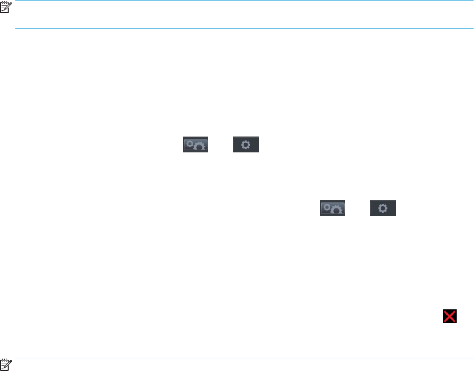
Introduction
System error codes are generally used to report internal system errors. The following pages contain a list of
system error codes with their descriptions and recommended corrective actions. Try only one recommended
action at a time, in the order in which they appear in this manual, and restart the printer after each action. If the
error code no longer appears, there is no need for any more corrective actions.
Errors of two kinds
Some system errors are continuable or advisory, which means that you can press OK on the front panel and
continue using the printer.
Other system errors are non-continuable, which means that you cannot continue using the printer. In this case,
turn the printer o and on again. If the error code reappears, then the printer requires an on-site visit in order to
resolve the problem.
Reporting a system error to HP Support
If you have an error code that you cannot resolve, then report the error to HP Support. When reporting the error,
have the following information ready.
NOTE: If you fail to provide any of this information, HP Support cannot help you properly. Make sure you take
time to gather all of the information.
●The model and serial number of the printer, which can be seen in Unit Information, in the Diagnostics
menu.
●Which rmware version the printer is using, which can be seen in Unit Information, in the Diagnostics menu.
●The complete error number, which can be seen in the Printer Information Area.
●The printer information or service plot of all pages. There are several ways of obtaining it:
–Go to the Control Panel, press , then , then Internal prints > printer usage information >
Service information prints.
–Through the EWS. To access the EWS you have 2 options. Open a web browser and type the IP
address of the printer. From the HP printer utility by clicking on the ADMIN tab and the launch the
EWS. Once you have access to the Embedded Web Server. Go to , then , then Service
Support > Printer information. Specic pages can be requested but it is recommended to request “all
pages” which contain all the printer information. Note that it can take a signicant amount of time to
generate. Once generated you may be asked to email the le to the support center helping you,
therefore you can save it from your Web browser, and later send the le, from Internet Explorer, for
example, you can send the page directly: select File > Send > Page by email.
●Which software application the customer is using.
●The internal error code, le, and line elds found on the internal error screens, available by pressing
when the system error is shown on the front panel. To get the le and line elds, you need to scroll down to
the next screen.
NOTE: The le and line elds are important to identify the source of the problem because the same internal
error code can be reported in dierent les and lines. In the File eld, supply only the lename: the part after the
last slash (/). For example, for a le /ae/…./elektra/ hal/motors/ControlledMotor/Elektra/
ControlledMotorElektra.cpp, you need to provide only the ControlledMotorElektra.cpp part to HP Support.
116 Chapter 3 System error codes ENWW

TIP: When investigating a system error, you are recommended to use the diagnostic package to further
understand the problem. To obtain the diagnostic package (which takes a few minutes), see Appendix C:
Obtaining the diagnostics package on page 177.
Diagnostic package
It is possible to view all the actions the printer performs collected in a log le. To further understand a system
error code, it is useful to have a log showing what the printer was doing at the time when the system error
occurred. To get the diagnostic package, see Appendix C: Obtaining the diagnostics package on page 177.
ENWW Introduction 117
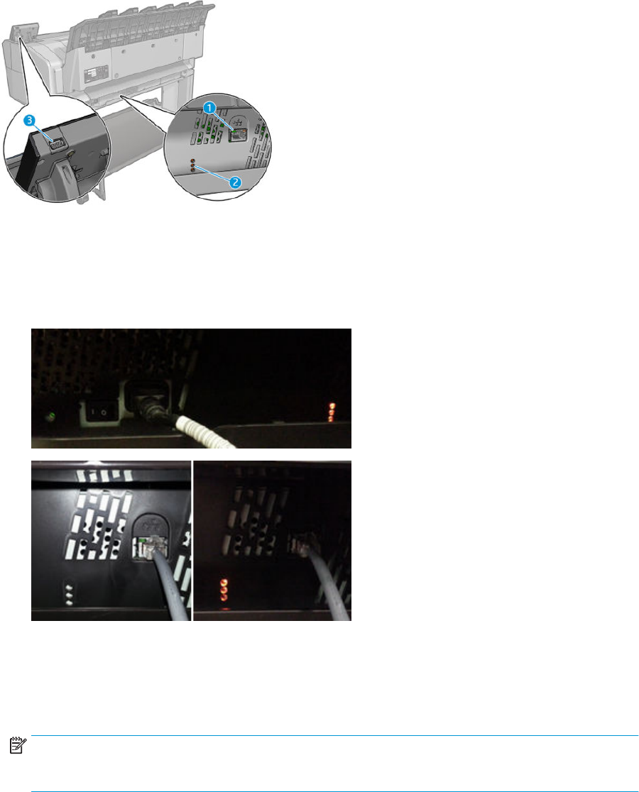
What to do if the front panel fails to initialize
The LEDs of the formatter (visible at the rear of the printer, see gure number 2 below), the power supply, and
the network interface card can help you troubleshoot a problem if the front panel is not working. All these LEDs
are located in the E-Box placed below the printer.
The call agent should ask the customer to follow these steps to troubleshoot the problem:
1. Switch the power o at the rear of the printer and disconnect the power cord. Reconnect the power cord
and switch on the printer.
2. Check that the front panel interface cable is undamaged and correctly corrected to the engine PCA.
3. Use the following table to interpret the LEDs and nd the source of the problem. Remember that you
should read these LEDs when you press the power button. Some combinations may require the
replacement of more than one component. In this case, always replace one component at a time. Check
the LEDs again to see whether the problem has disappeared. If the same LED sequence appears, replace
the next component indicated in the table.
NOTE: Once the printer has gone through the "Ready" state, the LEDs are no longer representative; in
particular you will notice that on waking from "Sleep mode" the LEDs turn to PSU-On, Upper-On, Mid-
blinking and Lower-O.
118 Chapter 3 System error codes ENWW

PSU LED Upper Mid Lower Problem and recommendations
O O O O The printer is not receiving electrical power.
1. Ensure that the printer is connected to the power outlet.
2. Ensure that the outlet delivers the expected power.
3. Replace the power supply unit.
On O O O There is a possible power failure in the formatter.
1. Reseat the power connector in the formatter.
2. Replace the formatter.
3. Replace the power supply unit.
On On O O The formatter BIOS is unable to start.
1. Update the BIOS.
2. Replace the formatter.
On Blinking O O The formatter BIOS cannot detect the hard disk drive.
1. Reseat the hard disk drive connectors.
2. Replace the hard disk drive.
3. Replace the formatter.
On On Blinking O The operating system has experienced a fatal error.
1. Proceed with a File system check.
2. Replace the hard disk drive.
On On On O There is a communication failure with the engine PCA.
1. Reseat the engine PCA.
2. Replace the engine PCA.
On On On Blinking There is a possible failure in the engine PCA.
▲Replace the engine PCA.
On On On On There is a communication failure in the front panel.
1. Ensure that the front panel cable is properly connected to the
formatter.
2. Replace the front panel.
Finally, there’s another case where the printer seems to be in sleep mode but is not able to boot. All the
formatter LEDs are o, but the PSU LED is On.
ENWW What to do if the front panel fails to initialize 119

Front
Power
(Blue)
Button PSU LED Upper Mid Lower Problem and recommendations
Flashing
(like in
sleep
mode)
On O O O There’s a short-circuit in the 32v power line. The printer seems to
be in sleep mode, but is not able to boot. All the formatter LEDs are
O.
1. Replace the engine PCA.
2. If the problem persists, replace the power supply unit.
120 Chapter 3 System error codes ENWW
System error codes in brief
Reading a system error code
System error codes explain which component or system is failing, and what action should be taken to resolve
the problem.
System error codes are displayed directly on the front panel’s home page (they can also be seen on the
Information page) and have been dened in the format XX.YZ. or XX.n:YZ.m.
●XX: Subsystem or process (2 digits)
●n or m: Subsystem or process index (optional), for example to identify the color of the ink cartridge
●Y: Who should perform the action (1 digit): 0 for user or 1 for service engineer
●Z: Action to perform (1 digit)
Subsystems
The following table explains the XX part of the system error code.
Code Component or system
01 Engine PCA
02 Carriage PCA
03 Power supply unit and E-Box fans
05 Formatter and BIOS
06 Hard disk drive
08 Front panel
11 Trailing cable
21 Service station
22 Ink supply station
24 Tube assembly (IDS)
26.n Ink cartridge (n=color)
27 Drop detector/Printhead
39 Roll switches
41 Paper-axis motor
42 Scan-axis motor
45 Rewinder
46 Pumps
47 Starwheel motor
48 PRS mechanism
52 Drop detector
54 Pinchwheel motor
ENWW System error codes in brief 121
Code Component or system
55 Line sensor
56 Drive roller analog encoder sensor
59 Component authentication
60 Printer setup
61 Printing language
63 Input/output through LAN card
71 Memory management
72 Calibration
74 Firmware update
76 Hard disk full
78 Paper settings
79 Firmware
80 Stacker overdrive motor
81 Paper advance
86 Scan axis
87 Scan-axis encoder
89 Stacker ramp motor
90 Valve motor
93 Ink Delivery System
Actions for customers
The following table explains the YZ part of the system error code.
Code Action
00 Replace
01 Reseat/Reconnect/Clean/Adjust (manually)
02 Calibrate/Adjust (using automatic process)
03 Restart the printer
04 Update rmware
05 Update software
06 Add accessory
07 Escalate
08 Send print again
09 Wrong part installed
122 Chapter 3 System error codes ENWW
Actions for qualied HP personnel
The following table explains the YZ part of the system error code.
Code Action
10 Replace
11 Reseat/Reconnect/Clean/Adjust (manually)
12 Calibrate/Adjust (using automatic process)
13 Turn o the printer
14 Update rmware
15 Update software
16 Add accessory
17 Escalate
18 Send print again
19 Wrong part installed
20 Replacement recommended but not essential
ENWW System error codes in brief 123

System error codes in full
This section describes each of the system error codes that may be encountered while using the printer and
suggests actions to solve the problem in each case.
IMPORTANT: Try only one recommended action at a time, in the order in which they appear in this manual, and
restart the printer after each action (unless the action was to restart the printer). If the error code no longer
appears, there is no need for any more corrective actions.
01.7:10 Communication errors between engine PCA and formatter
Call agent:
▲Use the power switch at the rear to turn o the printer, then disconnect the power cord. Reconnect the
power cord, and then turn on the printer.
Service engineer:
1. Clean the gold contacts from the engine PCA connector
2. Replace the formatter.
3. If the problem persists, replace the Engine PCA. See Engine PCA on page 314.
01.0:10 Problem with the engine PCA
Call agent:
▲Use the power switch at the rear to turn o the printer, then disconnect the power cord.
Reconnect the power cord, then turn on the printer.
Service engineer:
▲Replace the engine PCA. See Engine PCA on page 314.
NOTE: If the 01.0:10 is not solved after replacing the engine PCA, or after replacing it a SE 02.1:10 code
appears (carriage PCA), check the trailing cable to engine PCA connection; It's low probability, but possible,
that a wrong connection could cause the damage to the carriage PCA and / or engine PCA.
01.1:10 Error in the engine PCA
Call agent:
▲Use the power switch at the rear to turn o the printer, then disconnect the power cord.
Reconnect the power cord, then turn on the printer.
Service engineer:
▲Replace the engine PCA. See Engine PCA on page 314
NOTE: If the 01.1:10 is not solved after replacing the engine PCA, or after replacing it a SE 02.1:10 code
appears (carriage PCA), check the trailing cable to engine PCA connection; It's low probability, but possible,
that a wrong connection could cause the damage to the carriage PCA and / or engine PCA.
124 Chapter 3 System error codes ENWW

01.2:10 Problem with the backup NVM
Call agent:
▲Use the power switch at the rear to turn o the printer, then disconnect the power cord.
Reconnect the power cord, then turn on the printer.
Service engineer:
1. Check that the Encoder PCA Cable is correctly connected.
2. If the cable is correctly connected, replace the encoder PCA. See Motor Media Advance Transmission with
Encoder on page 379.
NOTE: The backup NVM is located in the Paper Path Encoder PCA. In order to replace this part, you need
to order the service kit CR357-67009 " Motor Media Advance Transmission with Encoder", then only use
the Encoder PCA part from this kit.
01.7:10 Communication errors between engine PCA and formatter
Call agent:
▲Use the power switch at the rear to turn o the printer, then disconnect the power cord.
Reconnect the power cord, then turn on the printer.
Service engineer:
1. Replace the formatter.
2. If the problem persists, replace the engine PCA. See Engine PCA on page 314.
02.1:10 Problem with the carriage PCA
Call agent:
▲Use the power switch at the rear to turn o the printer, then disconnect the power cord.
Reconnect the power cord, then turn on the printer.
Service engineer:
1. Check that the Trailing Cable is correctly connected between the Engine PCA and Carriage PCA.
2. Replace the carriage PCA. See Carriage PCA on page 327.
NOTE: If the 02.1:10 is not solved after replacing the carriage PCA or after replacing it a SE 1.0:10 or SE
01.1:10 code appears (engine PCA), check the trailing cable connection to the engine PCA.; It's low
probability, but possible, that a wrong connection could cause the damage to the carriage PCA and / or
engine PCA.
ENWW System error codes in full 125

03.2:10 Problem with the E-Box cooling fans
Call agent:
▲Use the power switch at the rear to turn o the printer, then disconnect the power cord.
Reconnect the power cord, then turn on the printer.
Service engineer:
1. Check the fans to see which is not rotating by checking for airow coming from the ebox; place a hand over
the fan holes in the ebox underneath the printer to check for air coming from both fans.
2. Remove the E-Box (see Open the E-Box on page 304) open it, and check that the cable of the non-
functional cooling fan is correctly connected. Reconnect the power cord and power on the E-Box. Check
whether the fan is now rotating.
3. Replace the fan. See E-Box fan on page 308.
4. Check the Power connection from PSU to Formatter and engine PCA.
5. Replace the PSU. See Power supply unit on page 311.
03:10 Problem with the power supply unit
Call agent:
▲Use the power switch at the rear to turn o the printer, then disconnect the power cord. Reconnect the
power cord, then turn on the printer.
Service engineer:
1. Check the cabling coming from the power supply to the Engine PCA.
2. Replace the PSU. See Power supply unit on page 311.
05.1:10 Problems with the formatter FAN
Call agent:
▲Use the power switch at the rear to turn o the printer, then disconnect the power cord.
Reconnect the power cord, then turn on the printer.
Service engineer:
▲Replace the formatter. See Formatter PCA on page 315.
05.4:10 BIOS data corrupted in formatter
Call agent:
▲Replace the formatter. See Formatter PCA on page 315.
05.5:10 BIOS should be updated (advisory)
Call agent:
▲Update the formatter BIOS.
126 Chapter 3 System error codes ENWW

05.7:10 Synchronization problems between control panel and formatter
Call agent:
1. Disconnect any device connected to the USB host in the front panel.
2. Use the power switch at the rear to turn o the printer, then disconnect the power cord.
Reconnect the power cord, then turn on the printer.
Service engineer:
1. Replace the front panel. See Front panel on page 318.
2. If after replacing the front panel, the SE continues to appear; replace the formatter PCA. See Formatter PCA
on page 315.
06:03 and 06:10 Problems with NVM in hard disk
Call agent:
▲Use the power switch at the rear to turn o the printer, then disconnect the power cord.
Reconnect the power cord, then turn on the printer.
Service engineer:
▲Replace the hard disk drive. See Hard disk drive on page 313.
06.1:10 Hard disk not detected
Call agent:
▲Use the power switch at the rear to turn o the printer, then disconnect the power cord.
Reconnect the power cord, then turn on the printer.
Service engineer:
1. Remove the E-Box (see Open the E-Box on page 304) open it, and check that the hard disk’s power and
data cables are correctly connected.
2. Replace the hard disk drive. See Hard disk drive on page 313.
3. If after replacing the hard disk in the front panel the SE continues to appear; replace the formatter PCA. See
Formatter PCA on page 315.
06.2:10 Hard disk cannot be unlocked
Call agent:
▲Use the power switch at the rear to turn o the printer, then disconnect the power cord.
Reconnect the power cord, then turn on the printer.
ENWW System error codes in full 127

Service engineer:
1. Remove the E-Box (see Open the E-Box on page 304) open it, and check that the hard disk’s power and
data cables are correctly connected.
2. Replace the hard disk drive. See Hard disk drive on page 313.
06.3:10 Hard disk is corrupted
Call agent:
▲Use the power switch at the rear to turn o the printer, then disconnect the power cord.
Reconnect the power cord, then turn on the printer.
Service engineer:
1. Remove the E-Box (see Open the E-Box on page 304) open it, and check that the hard disk’s power and
data cables are correctly connected.
2. Replace the hard disk drive. See Hard disk drive on page 313.
08:04 Communication lost between front panel and formatter
Call agent:
1. Restart the printer.
2. Update the rmware.
Service engineer:
1. Check that the front panel is correctly connected.
2. Replace the front panel. See Front panel on page 318.
3. If after replacing the front panel the SE continues to appear; replace the formatter PCA and the network
interface PCA. See Formatter PCA on page 315.
08:08 A front panel icon does not work (advisory)
Call agent:
1. Restart the printer.
2. Update the rmware.
08:10 Problems detected in the front panel Hardware
Call agent:
▲Use the power switch at the rear to turn o the printer, then disconnect the power cord. Reconnect the
power cord, then turn on the printer.
Service engineer:
1. Check that the front panel is correctly connected.
2. Replace the front panel. See Front panel on page 318.
128 Chapter 3 System error codes ENWW

08:11 Communication lost between front panel and printer
Call agent:
1. Restart the printer.
2. Update the rmware.
Service engineer:
1. Check that the front panel is correctly connected.
2. Replace the front panel. See Front panel on page 318.
3. If after replacing the front panel the SE continues to appear; replace the formatter PCA. See Formatter PCA
on page 315.
09:01 Media jam in Scanner
Call agent:
1. Turn o the product using the power key at the front, then also turn o the power switch at the rear and
disconnect the power cable.
2. There is a small lever at the rear left of the scanner. Slide the lever to the right and open the scanner cover.
3. Solve the media jam.
4. Check and clean the pressure rollers.
5. Close the scanner cover and gently push it down to lock it into place.
6. Reconnect the product’s power cable; turn on the power switch at the rear, and turn on the product using
the power key. If no paper is seen:
a. Open the scanner cover. Underneath you should see red, then green, then blue ashing lights.
b. In the center of the scanner cover, between the ashing lights, you will nd 4 small sensors labeled as R,
G, B and L. Put your ngers over the R, G and B sensors simultaneously and the scanner motor should
advance.
Service engineer:
▲If there is no response from the scanner motor, replace the Engine PCA. See Engine PCA on page 314.
Additional information
Currently, the batch scanning operation mode works as follows:
When the rst page is scanned, it is not released until the next page is fed in. If customers insert the next page
but want to correct skew removing and placing it back, the scanner rmware understands that both pages are
the same, therefore, the rst one is not released and is also rewound.
In this situation, input and output sensors are covered, and trigger System Error 09:01 or 09:03.
ENWW System error codes in full 129
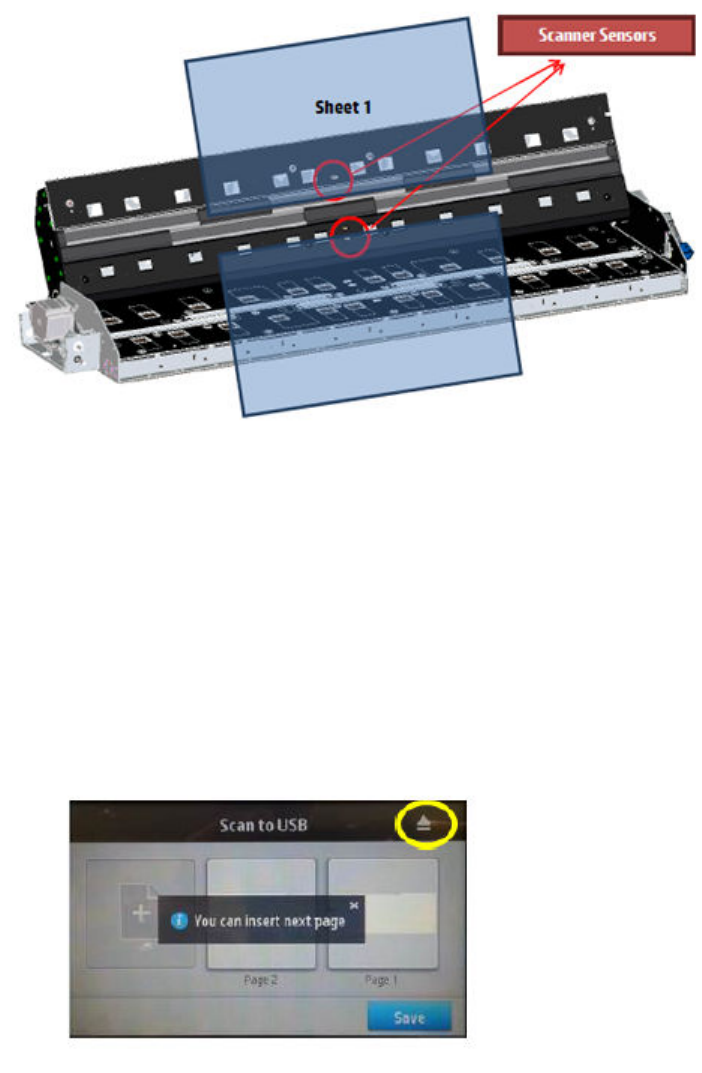
To prevent the situation, scanned pages should be released once they have been scanned, in this way the output
sensor is left free and no System Error will appear.
The rmware x to this issue will be included in the next release, scheduled December 2014.
Workaround
To avoid Scanner errors on Multi-page or multi-job scanning, explain to the user how to use the multipage or
batch scanning workow:
●The recommendation is NOT to stack scanned originals. Stacked originals may cause jams as they can hide
the stacker printing area, increasing the chance of possible conicts in workgroup environments.
●Users should press eject paper from the FP (eject symbol at top-right corner of the touch screen) each time
before scanning next page.
09:01:10 Scanner Motor is failing
Call agent:
1. Reboot the printer.
2. If system error persists, upgrade to the latest rmware.
130 Chapter 3 System error codes ENWW
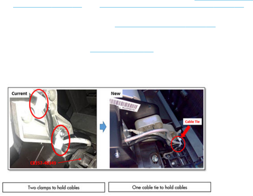
3. Open the scanner cover. Underneath you will see red, then green, then blue ashing lights.
4. In the center of the scanner cover, between the ashing lights, you will nd 4 small sensors labeled as R, G,
B and L. Put your ngers over the R, G and B sensors simultaneously and the scanner motor should
advance.
Service engineer:
1. If there is no response from the scanner motor, replace the Engine PCA, See Engine PCA on page 314. See
Open the E-Box on page 304 or See Stepper Motor Assembly (taco sensor, and belt) on page 435, see
Scanner Motor Assembly (MFP only).
2. Replace the Scanner Controller Board. See Scanner Controller Unit (SUP) on page 430.
3. Check the scanner controller board cable connections and replace the cables if required.
4. Replace the media sensors, See Media Sensor on page 357 (MFP only).
Additional troubleshooting
Ensure that the Scanner routing cable is correct.
The process of routing the new cable:
1. Unfasten the two nuts and remove the clamps.
ENWW System error codes in full 131
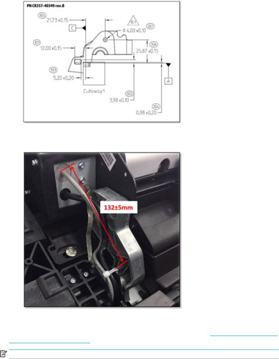
2. Replace PN CR357-40349, assembling it as shown below in rev.B.
3. Mark the grey cable at 132±5 mm. This mark is the reference to use with the Cable Tie. The minimum
distance has to be the one gotten with the scanner closed.
4. Pass the Cable Tie (1400-3401) through the hole to hold the cables exactly as shown above.
If SE09:01:10 and SE09:10:10 are still occurring, check the steps above and refer to 09:10:10 Scanner Controller
Board (SCU) is failing on page 135 troubleshooting.
NOTE: Please note that from SN CN7PF04M00 onwards this rework is already done on the manufacturing side.
132 Chapter 3 System error codes ENWW

09:02 Scanner not calibrated
▲Calibrate the Scanner.
09:02:10 CIS A Element is failing
Call agent:
1. Clean the scanner of dust and dirt and perform the Scanner Calibration.
2. If the system error persists, upgrade with latest rmware version.
Service engineer:
1. Replace CIS A Element.
2. Replace Scanner Controller Board (SCU). See Scanner Controller Unit (SUP) on page 430.
09:03 File I/O Error
Call agent:
1. Reboot the product.
2. Upgrade to the latest rmware.
3. Go to Jobs > Options > Delete all queue scan jobs.
4. Make sure the hard disk that is installed in the printer is the correct one for the product you are repairing.
5. Check and clean scanner elements.
6. Calibrate the scanner.
Service engineer:
▲In some corner cases, the issue could be related to media movement. Replace the media sensors. See
Media Sensor on page 357.
Additional information
See Additional Information in SE 09:01 Media jam in Scanner on page 129
09:03:10 CIS B Element is failing
Call agent:
1. Clean the scanner of dust and dirt and perform the Scanner Calibration.
2. If the system error persists, upgrade with latest rmware version.
Service engineer:
1. Replace CIS B Element.
2. Replace Scanner Controller Board (SCU). See Scanner Controller Unit (SUP) on page 430.
ENWW System error codes in full 133

09:04 Library failed to load.
Call agent:
1. Reboot the product.
2. Upgrade to the latest rmware.
09:04:10 CIS C Element is failing
Call agent:
1. Clean the scanner of dust and dirt and perform the Scanner Calibration.
2. If the system error persists, upgrade with latest rmware version.
Service engineer:
1. Replace CIS C Element.
2. Replace Scanner Controller Board (SCU). See Scanner Controller Unit (SUP) on page 430.
09:05:10 CIS D Element is failing
Call agent:
1. Clean the scanner of dust and dirt and perform the Scanner Calibration.
2. If the system error persists, upgrade with latest rmware version.
Service engineer:
1. Replace CIS D Element.
2. Replace Scanner Controller Board (SCU). See Scanner Controller Unit (SUP) on page 430.
09:06:10 CIS E Element is failing
Call agent:
1. Clean the scanner of dust and dirt and perform the Scanner Calibration.
2. If the system error persists, upgrade with latest rmware version.
Service engineer:
1. Replace CIS E Element.
2. Replace Scanner Controller Board (SCU). See Scanner Controller Unit (SUP) on page 430.
09:08:11 Power cable of the Scanner is failing
Service engineer:
▲Check the condition and connections of the Scanner Power cable, if necessary replace the cable.
09:09:11 USB cable of the Scanner is failing
Service engineer:
134 Chapter 3 System error codes ENWW

▲Check the condition of the Scanner USB cable and its connections, if necessary replace the cable.
09:10:04 Scanner is in SAFE MODE
Service engineer:
▲Restart the product, if the problem persists replace the SCU. See Scanner Controller Unit (SUP)
on page 430.
09:10:10 Scanner Controller Board (SCU) is failing
Call agent:
1. Turn o the product (20 sec.) using the Power key at the front, then also turn o the power switch at the
rear and disconnect the power cable.
2. Perform the Scanner Calibration.
3. If the system error persists, upgrade with latest rmware version.
4. Perform File System Check.
5. Perform the Scanner Validation.
Service engineer:
1. Check the USB cable connection.
2. Replace the Scanner SCU. See Scanner Controller Unit (SUP) on page 430.
3. Check the Scanner USB cable connection and the Power/Reset/Awake cable from the Scanner Controller
Board to the Interconnect PCA; replace if broken.
4. Replace the Interconnect PCA.
Additional troubleshooting
Please check SE 09:01:10 Scanner Motor is failing on page 130 for additional troubleshooting information.
11:10 Trailing cable does not seem to be detected
Call agent:
▲Use the power switch at the rear to turn o the printer, then disconnect the power cord.
Reconnect the power cord, then turn on the printer.
Service engineer:
1. Check that the trailing cable is correctly connected between the engine PCA and carriage PCA.
2. Check that the trailing cable connectors are not damaged, especially on the E-Box side; replace the trailing
cable if necessary.
3. Check that the power cable from the power supply unit is connected to the formatter.
4. Replace the carriage PCA. See Carriage PCA on page 327.
5. Replace the engine PCA. See Engine PCA on page 314.
ENWW System error codes in full 135

21.2:13 Failure moving service station
Call agent:
1. Use the power switch at the rear to turn o the printer, then disconnect the power cord. Check the Primer
Tubes.
Reconnect the power cord, then turn on the printer.
2. Ensure that the service station path is clear. Remove any visible obstacles (screws, plastic parts, etc.)
restricting the movement of the service station.
3. If the carriage has stopped over the service station, on the left of the printer, check that the cutter is not
activated. The cutter may be blocking the carriage over the service station, preventing the service station
from moving correctly. The cutter is on the right side of the carriage.
4. Perform the service station diagnostic test to troubleshoot the problem further.
Service engineer:
▲Replace the service station. See Service Station with Drop Detector on page 339.
21:13 Problem with the Service Station motor
Call agent:
1. Ensure that the service station path is clear. Remove any visible obstacles (screws, plastic parts, etc.)
restricting the movement of the service station.
2. If the carriage has stopped over the service station, on the left of the printer, check that the cutter is not
activated. The cutter may be blocking the carriage over the service station, preventing the service station
from moving correctly. The cutter is on the right side of the carriage.
3. Perform the service station diagnostic test to troubleshoot the problem further.
Service engineer:
1. Use the power switch at the rear to turn o the printer, then disconnect the power cord.
Reconnect the power cord, then turn on the printer.
2. Replace the service station. See Service Station with Drop Detector on page 339.
22.0:00 Service-station-side ink supply station error
Call agent:
1. Use the power switch at the rear to turn o the printer, then disconnect the power cord.
Reconnect the power cord, then turn on the printer.
2. Perform the ink delivery system diagnostic test to troubleshoot the problem further.
136 Chapter 3 System error codes ENWW

Service engineer:
1. Check that the cables between the ink supply station and the engine PCA are not damaged and are
properly connected. In case of any damage, replace the cable.
2. Replace the ink supply station on the service station side.
3. Replace the engine PCA. See Engine PCA on page 314.
22.1:00 Front-panel-side ink supply station error
Call agent:
1. Use the power switch at the rear to turn o the printer, then disconnect the power cord.
Reconnect the power cord, then turn on the printer.
2. Perform the ink delivery system diagnostic test to troubleshoot the problem further.
Service engineer:
1. Check that the cables between the ink supply station and the engine PCA are not damaged and are
properly connected. In case of any damage, replace the cable.
2. Replace the ink supply station on the front panel side.
3. Replace the engine PCA. See Engine PCA on page 314.
24:10 Error detected in ink tube system
Call agent:
▲Use the power switch at the rear to turn o the printer, then disconnect the power cord.
Reconnect the power cord, then turn on the printer.
Service engineer:
1. Perform the Ink Delivery System diagnostic test in order to check that the bongos (pushers) go up and
down to pressurize ink in the tube, and the Out of Ink sensors work properly.
2. If the diagnostic test does not nd any problem, install new cartridges,and the printhead, and try purging
the Ink Supply Tubes again.
3. If the problem persists, replace the Ink Supply Tubes. See Ink Tubes and Trailing Cable on page 354.
26:01 Ink supply error found during IDS diagnostic test (advisory)
In the front panel message you can see letters representing the names of the colors of the faulty supplies.
Call agent:
1. Reseat the faulty ink supply and repeat the ink delivery system diagnostic test.
2. Replace the faulty ink supply and repeat the ink delivery system diagnostic test.
Service engineer:
▲Replace the left ink supply station.
ENWW System error codes in full 137
27:01 Too many nozzles out detected (Advisory)
Call agent:
1. Print the “Nozzle health” diagnostic print from the service menu. If printhead shows many nozzles out,
replace the printhead.
2. If printhead doesn’t show too many nozzles out, run “drop detector calibration”.
Service engineer:
▲If printhead doesn’t have too many nozzles out and “drop detection calibration” doesn’t help, replace the
drop detector.
39.11:01 Media unloaded (Advisory)
Symptom
Plot cut partially and part of the image is kept in the unloaded roll.
This warning may happen in the following situations:
●When an end of roll 1 is detected because end of media is glued to the core.
●Paper has been unloaded before its end due to several reasons. In the cases bellow an excess of friction is
causing malfunction in the media input which ends in unexpected media unloads:
○Blue hub not completely introduced in the Media Roll core
○Black Hub is broken and shifted to the left
○Media sides are brushing the hubs for dierent conditions such as:
■Media has expanded due to climate conditions (for example, switching o Air Conditioning)
■Poor quality media: Media telescoping, core is narrower than media
Call agent:
1. Upgrade the printer to the latest rmware.
2. Ask customer if the advisory has appeared when reaching the end of the roll. In that case it is expected
behavior. Tell customer to load new media roll and continue printing.
3. Ask customer to open roll cover and feed media into the media path.
a. Check if media sides are brushing the hubs. In that case tell customer to re-position the media roll on
the spindle ensuring a margin (≈3mm) between the sides of the media and the black and blue hubs
and observe there is no brushing. If this is not the case continue troubleshooting as described below
b. Visually check that the hubs (black and blue pieces) are not broken. If they are, send a new spindle to
the customer.
4. If problem persists, send a Service Engineer with a new spindle a new rewinder motor.
Service engineer:
1. Follow all the steps from call agent section.
138 Chapter 3 System error codes ENWW

2. Measure distance of the Black hub on the left (as shown in picture below). This distance should be greater
than 4 cm. Otherwise the black hub may be broken. Send a new spindle. Meanwhile recommend the
customer to use roll 2 spindle if available.
3. If customer is using 36 inch paper roll width, measure distance on the blue hub on the right (as shown in
picture below). This distance should be greater than 4.5 cm otherwise, the blue hub is probably not
completely inserted into the roll core.
4. Clean the media path for visual inspection:
a. Disconnect and unroute the sensor from under the printer.
ENWW System error codes in full 139
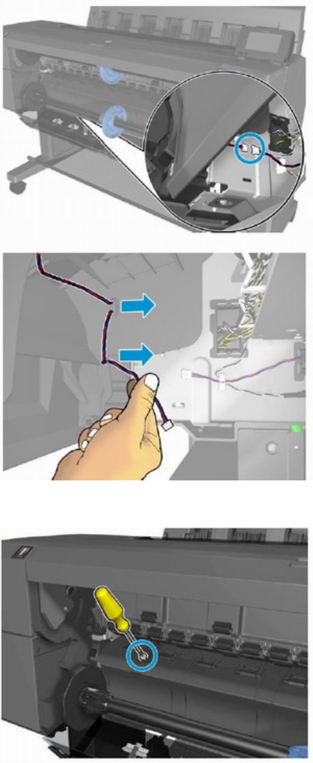
b. Remove the T-15 cosmetic screw.
5. Remove the Cleanout Assy and visually check there are no obstructions in media path such as loose parts,
plastics/foams/paper pieces.
6. If problem persists, replace spindle.
7. If problem persists, replace "rewinder motor"
140 Chapter 3 System error codes ENWW
39.12:01 Media unloaded (Advisory)
Symptom
Plot cut partially and part of the image is kept in the unloaded roll.
This warning may happen in the following situations:
●When an end of roll 2 is detected because end of media is glued to the core.
●Paper has been unloaded before its end due to several reasons. In the cases bellow an excess of friction is
causing malfunction in the media input which ends in unexpected media unloads:
○Blue hub not completely introduced in the Media Roll core
○Black Hub is broken and shifted to the left
○Media sides are brushing the hubs for dierent conditions such as:
■Media has expanded due to climate conditions (for example, switching o Air Conditioning)
■Poor quality media: Media telescoping, core is narrower than media
Call agent:
1. Upgrade the printer to the latest rmware.
2. Ask customer if the advisory has appeared when reaching the end of the roll. In that case it is expected
behavior. Tell customer to load new media roll and continue printing.
3. Ask customer to open roll cover and feed media into the media path.
a. Check if media sides are brushing the hubs. In that case tell customer to re-position the media roll on
the spindle ensuring a margin (≈3mm) between the sides of the media and the black and blue hubs
and observe there is no brushing. If this is not the case continue troubleshooting as described below
b. Visually check that the hubs (black and blue pieces) are not broken. If they are, send a new spindle to
the customer.
4. If problem persists, send a Service Engineer with a new spindle a new rewinder motor.
Service engineer:
1. Follow all the steps from call agent section.
2. Mount roll 2 in roll 1 position.
ENWW System error codes in full 141
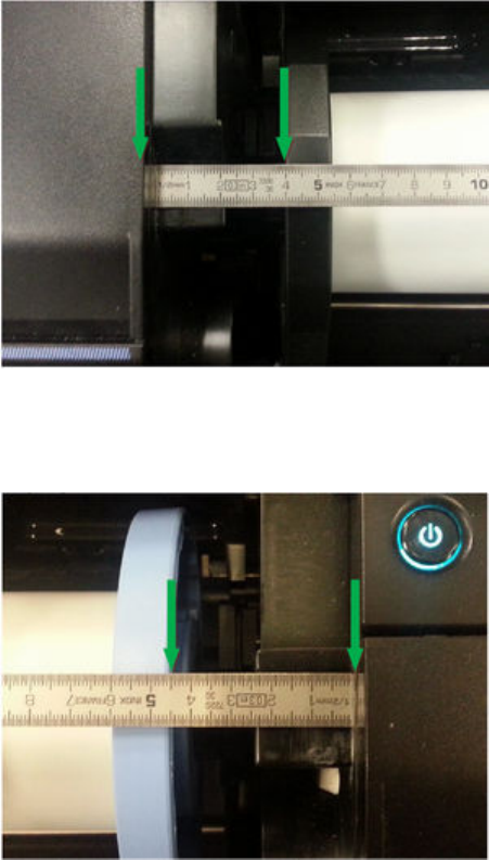
3. Measure distance of the Black hub on the left (as shown in picture below). This distance should be greater
than 4 cm. Otherwise the black hub may be broken. Send a new spindle. Meanwhile recommend the
customer to use roll 1 spindle if available.
4. If customer is using 36 inch paper roll width, measure distance on the blue hub on the right (as shown in
picture below). This distance should be greater than 4.5 cm otherwise, the blue hub is probably not
completely inserted into the roll core.
5. Clean the media path for visual inspection:
a. Disconnect and unroute the sensor from under the printer.
142 Chapter 3 System error codes ENWW

b. Remove the T-15 cosmetic screw.
6. Remove the Cleanout Assy and visually check there are no obstructions in media path such as loose parts,
plastics/foams/paper pieces.
7. If problem persists, replace spindle.
8. If problem persists, replace "rewinder motor"
ENWW System error codes in full 143

41:03 Electrical problem (fault, current limit, overheating) in paper-axis motor
Call agent:
1. Use the power switch at the rear to turn o the printer, then disconnect the power cord.
Reconnect the power cord, then turn on the printer.
2. Check for any visible obstacles restricting the movement of the paper advance roller. If there is a wrinkled
mass of paper inside the paper path, lift the pinchwheels (using the pinchwheels diagnostic test), and clear
the obstruction.
3. Perform the paper drive diagnostic test to troubleshoot the problem further.
Service engineer:
1. Check for any visible obstacles restricting the movement of the paper advance roller. If there is a wrinkled
mass of paper inside the paper path, lift the pinchwheels (using the screw that moves the pinchwheels, or
the pinchwheels diagnostic test) and clear the obstruction.
2. Check that the paper advance drive cable is undamaged and correctly corrected to the engine PCA.
3. Replace the paper advance drive.
4. Replace the engine PCA. See Engine PCA on page 314.
42:03 Electrical problem (fault, current limit, overheating) in scan-axis motor
Call agent:
1. Use the power switch at the rear to turn o the printer, then disconnect the power cord.
2. Reconnect the power cord, then turn on the printer.
3. Check for any visible obstacles restricting the movement of the carriage assembly. Remove any obstacle to
let the carriage move freely along the whole scan axis.
Service engineer:
1. Check that the scan-axis motor cable is undamaged and correctly corrected to the engine PCA.
2. Replace the scan-axis motor. See Scan Axis Motor on page 335.
3. Replace the engine PCA. See Engine PCA on page 314.
45.1:03 and 45.1:10 Error in the rewinder 1 system (upper rewinder)
Call agent:
1. Use the power switch at the rear to turn o the printer, then disconnect the power cord.
Remove the paper from roll 1.
Reconnect the power cord, then turn on the printer.
2. The rewinder will be tested automatically during boot up.
144 Chapter 3 System error codes ENWW

Service engineer:
1. Check that the rewinder 1 cable is undamaged and correctly connected to the engine PCA.
2. Replace the upper roll rewinder.
3. If the issue is not solved, replace the Engine PCA. See Engine PCA on page 314.
45.2:03 and 45.2:10 Error in the rewinder 2 system (lower rewinder)
Call agent:
1. Use the power switch at the rear to turn o the printer, then disconnect the power cord.
Remove the paper from roll 2.
Reconnect the power cord, then turn on the printer.
2. The rewinder will be tested automatically during boot up.
Service engineer:
1. Check that the rewinder 2 cable is undamaged and correctly connected to the engine PCA
2. Replace the lower roll rewinder.
3. If the issue is not solved, replace the Engine PCA. See Engine PCA on page 314.
46.1:10 Error in the upper pump of the PHA blowing system
Call agent:
▲Use the power switch at the rear to turn o the printer, then disconnect the power cord.
Reconnect the power cord, then turn on the printer.
Service engineer:
1. Check that the pump cable is undamaged and correctly corrected to the engine PCA.
2. Replace the upper pump.
46.2:10 Error in the lower pump of the PHA blowing system
Call agent:
▲Use the power switch at the rear to turn o the printer, then disconnect the power cord.
Reconnect the power cord, then turn on the printer.
Service engineer:
1. Check that the pump cable is undamaged and correctly corrected to the engine PCA.
2. Replace the lower pump.
ENWW System error codes in full 145

47:03 and 47:10 Starwheel motor error
Call agent:
1. Use the power switch at the rear to turn o the printer, then disconnect the power cord.
Reconnect the power cord, then turn on the printer.
2. Check for any visible obstacles restricting the movement of the starwheel assembly, then clear the
obstruction.
3. Perform the scan-axis starwheel diagnostic test to troubleshoot the problem further.
Service engineer:
1. Check that the starwheel assembly cable is undamaged and correctly corrected to the engine PCA.
2. Replace the starwheel motor. See Starwheel Motor on page 387.
3. Replace the engine PCA. See Engine PCA on page 314.
47.5:10 Problem at the starwheel lifter motor end of the travel sensor
Call agent:
1. Use the power switch at the rear to turn o the printer, then disconnect the power cord.
Reconnect the power cord, then turn on the printer.
2. Check for any visible obstacles restricting the movement of the starwheel assembly, then clear the
obstruction.
3. Perform the scan-axis starwheel diagnostic test to troubleshoot the problem further.
Service engineer:
1. Check that the starwheel lifter sensor cable is undamaged and correctly connected to the engine PCA.
2. Replace the starwheel lifter sensor. See Starwheel Motor on page 387.
3. Replace the engine PCA. See Engine PCA on page 314.
48:00 PRS Actuator system failure
Call agent:
1. Use the power switch at the rear to turn o the printer, then disconnect the power cord.
Reconnect the power cord, then turn on the printer.
2. Perform the scan-axis PRS diagnostic test to troubleshoot the problem further.
Service engineer:
1. Check that the PRS Actuator cable is undamaged and correctly connected to the engine PCA.
2. Replace the printhead-to-paper space solenoid.
3. Replace the engine PCA. See Engine PCA on page 314.
146 Chapter 3 System error codes ENWW

52:10 Drop detector failure
Call agent:
▲Use the power switch at the rear to turn o the printer, then disconnect the power cord.
Reconnect the power cord, then turn on the printer.
Service engineer:
1. Check that the drop detector cable is undamaged and correctly connected to the service station board.
2. Replace the drop detector. See Service Station with Drop Detector on page 339.
3. Replace the service station. See Service Station with Drop Detector on page 339.
54.4:03 Pinchwheel lifter motor error
Call agent:
1. Use the power switch at the rear to turn o the printer, then disconnect the power cord.
Reconnect the power cord, then turn on the printer.
2. Check for any visible obstacles restricting the movement of the pinchwheel assembly, then clear the
obstruction.
Service engineer:
1. Check that the pinchwheel motor assembly cable is undamaged and correctly connected to the engine
PCA.
2. Replace the pinchwheel lifter motor. See Pinch Wheel Assembly on page 376.
3. Replace the engine PCA. See Engine PCA on page 314.
55:10 Cannot access the line sensor EEPROM
Call agent:
1. Use the power switch at the rear to turn o the printer, then disconnect the power cord.
Reconnect the power cord, then turn on the printer.
2. Perform the carriage test to troubleshoot the problem further.
Service engineer:
1. Replace the line sensor. See Line Sensor on page 326.
2. Replace the carriage PCA. See Engine PCA on page 314.
ENWW System error codes in full 147

56:01 Drive roller analog encoder homing failed
Call agent:
1. Use the power switch at the rear to turn o the printer, then disconnect the power cord.
Reconnect the power cord, then turn on the printer.
2. Perform the paper path test to troubleshoot the problem further.
Service engineer:
1. Replace the encoder disk and encoder sensor.
2. Replace the engine PCA. See Engine PCA on page 314.
59.1:09 Two electrical parts have been replaced at the same time
Service engineer:
▲Replace one part at a time, and restart the printer before replacing another.
59.2:00 An unsupported or reused part has been installed
Service engineer:
▲Install only new parts recommended by HP for this printer.
59.3:10 Wrong information stored on CryptoAsic
Call agent:
▲Switch the power o at the rear of the printer, wait two minutes, then switch it back on again.
Service engineer:
▲Escalate the case to Level 3, requesting new CryptoAsic SIM licenses. Update the CryptoAsic SIM with the
delivered licenses.
59.4:10 CryptoAsic failure
Call agent:
▲Switch the power o at the rear of the printer, wait two minutes, then switch it back on again.
Service engineer:
1. Reseat the CryptoAsic SIM PCA.
2. Order an CryptoAsic SIM PCA Service Kit. Escalate to Level 3 providing printer Serial Number, Product
Number, and the serial number of the CryptoAsic SIM Service Kit. Replace the CryptoAsic SIM PCA. Write in
an empty USB the le provided by Level 3. Plug the USB in the printer and reboot. If booting fails, enable
diagnostic package with the USB and provide logs to Level 3.
3. Replace the engine PCA. See Engine PCA on page 314.
148 Chapter 3 System error codes ENWW

59.5:19 CryptoAsic type mismatch
Call agent:
▲Switch the power o at the rear of the printer, wait two minutes, then switch it back on again.
Service engineer:
1. Order an CryptoAsic SIM PCA Service Kit. Escalate to Level 3 providing printer Serial Number, Product
Number, and the serial number of the CryptoAsic SIM Service Kit. Replace the CryptoAsic SIM PCA. Write in
an empty USB the le provided by Level 3. Plug the USB in the printer and reboot. If booting fails, enable
diagnostic package with the USB and provide logs to Level 3.
2. Replace the engine PCA. See Engine PCA on page 314.
59.6:19 Printer serial number mismatch
Call agent:
▲Switch the power o at the rear of the printer, wait two minutes, then switch it back on again.
Service engineer:
1. Order an CryptoAsic SIM PCA Service Kit. Escalate to Level 3 providing printer Serial Number, Product
Number, and the serial number of the CryptoAsic SIM Service Kit. Replace the CryptoAsic SIM PCA. Write in
an empty USB the le provided by Level 3. Plug the USB in the printer and reboot. If booting fails, enable
diagnostic package with the USB and provide logs to Level 3.
2. Replace the engine PCA. See Engine PCA on page 314.
59.7:14 CryptoAsic generic error
Call agent:
▲Switch the power o at the rear of the printer, wait two minutes, then switch it back on again.
Service engineer:
▲Order an CryptoAsic SIM PCA Service Kit. Escalate to Level 3 providing printer Serial Number, Product
Number, and the serial number of the CryptoAsic SIM Service Kit. Replace the CryptoAsic SIM PCA. Write in
an empty USB the le provided by Level 3. Plug the USB in the printer and reboot. If booting fails, enable
diagnostic package with the USB and provide logs to Level 3.
60.1:11 Initialization error (cannot read RFID tag)
Call agent:
1. Switch the power o at the rear of the printer, wait two minutes, then switch it back on again.
2. Check the power cord; try connecting it to another power socket.
Service engineer:
1. Check that the RFID device is correctly connected.
2. If the error persists, get the diagnostic package (see Appendix C: Obtaining the diagnostics package
on page 177) and contact Level 3 providing print Serial Number and Product Number.
ENWW System error codes in full 149

60.2:17 Initialization error (RFID has incorrect data)
Call agent:
1. Switch the power o at the rear of the printer, wait two minutes, then switch it back on again.
2. Check the power cord; try connecting it to another power socket.
Service engineer:
1. Check that the RFID device is correctly connected.
2. If the error persists, get the diagnostic package (see Appendix C: Obtaining the diagnostics package
on page 177) and contact Level 3 providing print Serial Number and Product Number.
61:01 Incorrect or unsupported le format (advisory)
Call agent:
1. Check whether the printer supports the le format. Formats such as PS, PDF, TIFF, and JPEG are supported
by PostScript printers only.
2. Use the power switch at the rear to turn o the printer, then disconnect the power cord.
Reconnect the power cord, then turn on the printer.
3. Check the printer’s graphic language setting (see the user's guide).
4. Resend the le to the printer.
5. Update the rmware.
61:04.1 PostScript fonts seem to be missing (advisory)
Call agent:
▲Update the rmware to re-install the fonts.
61:04.2 Unknown PostScript ID sent to printer (advisory)
Call agent:
▲Update the rmware.
61:08 Incor rect paper type specied in job (advisory)
Call agent:
▲Change the paper type and resend the job.
61:08.1 Job cannot be printed because it is password-protected (advisory)
Call agent:
▲Resend the job without password protection.
150 Chapter 3 System error codes ENWW
61:08.2 Job contains format errors or incorrect settings (advisory)
Call agent:
1. Ensure that the le format sent is supported by the printer.
2. Resend the job using the Embedded Web Server.
61:09 Unexpected end of job (advisory)
Call agent:
1. Resend the job.
2. Resend the job using the Embedded Web Server.
61:10 Job timed out (advisory)
A slow computer processing complex les can pause for longer than the default printer timeout, in which case
some elements of the job may be lost.
Call agent:
1. Increase the I/O timeout using the printer's front panel (see 'Congure network settings' in the user’s
guide).
2. Resend the job from a faster computer.
3. Resend the job using the Embedded Web Server.
4. Use the “print to le” option in the driver and copy the resulting le to a USB ash drive. Print from the USB
ash drive.
63:04 Network interface error
Call agent:
1. Use the power switch at the rear to turn o the printer, then disconnect the power cord.
Reconnect the power cord, then turn on the printer.
2. Check that the network cable is correctly connected to the network interface.
3. Update the rmware.
Service engineer:
1. If the printer is blocked showing the system error persistently; check that the network interface card
(including the riser) are correctly connected.
2. If the printer is blocked showing the system error persistently; replace the network interface card.
Additional information
After waking up from sleep mode, the printer shows SE 63:04 and sometimes SE 79:04.
First of all, download the latest rmware release from hp.com. In the latest FW, there were improvements for
ePrint and Share connectivity.
ENWW System error codes in full 151

Follow the steps above to troubleshoot it. If the issue remains, follow this workaround:
▲Disabled ePrint Center:
From the front panel, press , then , then Connectivity ►HP ePrint Center Connectivity
►Disable.
The FW team are investigating this issue.
63:10 Network interface error
Call agent:
1. Use the power switch at the rear to turn o the printer, then disconnect the power cord.
Reconnect the power cord, then turn on the printer.
2. Check that the network cable is correctly connected to the network interface.
3. Update the rmware.
Service engineer:
1. Check that the network interface card (including the riser) are correctly connected.
2. Replace the network interface card.
63:20 Potential problem in the network interface (advisory)
Call agent:
1. Use the power switch at the rear to turn o the printer, then disconnect the power cord.
Reconnect the power cord, then turn on the printer.
2. Check that the network cable is correctly connected to the network interface.
3. Update the rmware.
Service engineer:
1. Check that the network interface card (including the riser) are correctly connected.
2. Replace the network interface card.
71:03 Out of memory
Call agent:
1. Use the power switch at the rear to turn o the printer, then disconnect the power cord.
Reconnect the power cord, then turn on the printer.
2. Resend the job with one or more of the following changes:
●Decrease resolution to 300 dpi.
●Select Economode print mode.
●Select the Send job as bitmap option.
152 Chapter 3 System error codes ENWW

71:08 Insucient display list
Call agent:
1. Use the power switch at the rear to turn o the printer, then disconnect the power cord.
Reconnect the power cord, then turn on the printer.
2. Resend the job with one or more of the following changes:
●Decrease resolution to 300 dpi.
●Select Economode print mode.
●Select the Send job as bitmap option.
72.02 A service calibration should be performed (advisory)
Call agent:
▲To nd out which service calibration to perform, print the calibration status. At the front panel, press ,
then , then Internal prints > Service information prints > Print calibration status. Perform whichever
calibration is needed.
74:01 Error uploading rmware update le (advisory)
Call agent:
1. Use the power switch at the rear to turn o the printer, then disconnect the power cord.
Reconnect the power cord, then turn on the printer.
2. Ensure that the connection between the computer and the printer is functioning properly.
3. Try again to upload the rmware update le.
74.1:04 Error uploading paper preset (advisory)
Call agent:
1. Use the power switch at the rear to turn o the printer, then disconnect the power cord.
Reconnect the power cord, then turn on the printer.
2. Ensure that the connection between the computer and the printer is functioning properly.
3. Try again to upload the paper preset.
4. Ensure that the version of the paper preset is compatible with the rmware version in the printer. You can
check this on the same Web page from which you downloaded the paper preset.
ENWW System error codes in full 153

74.08:04 Firmware update problem
Call agent:
1. Use the power switch at the rear to turn o the printer, then disconnect the power cord.
Reconnect the power cord, then turn on the printer.
2. Try again to update the rmware. If necessary, see Appendix B: Updating rmware in boot mode
on page 176.
3. Download the rmware le again, as the le that you have may be corrupted.
Service engineer:
▲Replace the front panel. See Front panel on page 318.
76:03 The hard disk is full
Call agent:
1. Remove any unnecessary les from the hard disk using the Embedded Web Server.
2. Run the Hard Disk Recovery Utility.
78:08 Paper does not support borderless printing (advisory)
Call agent:
▲Use a paper type that supports borderless printing.
NOTE: This should be resolved by the customer without assistance.
78.1:04 Paper settings area missing in paper settings le (advisory)
Call agent:
1. Use the power switch at the rear to turn o the printer, then disconnect the power cord.
Reconnect the power cord, then turn on the printer.
2. Update the rmware.
79:03 Generic rmware error
Call agent:
1. Use the power switch at the rear to turn o the printer, then disconnect the power cord.
Reconnect the power cord, then turn on the printer.
2. Update the rmware.
3. Information available by pressing while viewing the system error screen; or, preferably, provide the
diagnostic package. See Appendix C: Obtaining the diagnostics package on page 177.
154 Chapter 3 System error codes ENWW

79:04 Generic rmware error
Call agent:
1. Use the power switch at the rear to turn o the printer, then disconnect the power cord.
Reconnect the power cord, then turn on the printer.
2. Update the rmware.
3. See Appendix A: How to troubleshoot system error 79:04 and 79.2:04 on page 164.
4. Information available by pressing while viewing the system error screen; or, preferably, provide the
diagnostic package. See Appendix C: Obtaining the diagnostics package on page 177.
79.2:04 Generic Operating System error
Call agent:
1. Use the power switch at the rear to turn o the printer, then disconnect the power cord.
Reconnect the power cord, then turn on the printer.
2. Update the rmware.
3. See Appendix A: How to troubleshoot system error 79:04 and 79.2:04 on page 164.
4. Information available by pressing while viewing the system error screen; or, preferably, provide the
diagnostic package. See Appendix C: Obtaining the diagnostics package on page 177.
80:03 Stacker overdrive motor error
Call agent:
1. Use the power switch at the rear to turn o the printer, then disconnect the power cord.
Reconnect the power cord, then turn on the printer.
2. Test the cutter. Perform a 'Form Feed & Cut', and verify the paper can be cut. See The cutter does not cut
well on page 68.
3. Perform the stacker overdrive motor diagnostic test to troubleshoot the problem further.
Service engineer:
1. Check that the stacker overdrive motor cable is undamaged and correctly connected to the engine PCA.
2. Replace the stacker overdrive motor. See Overdrive on page 396.
3. Perform the stacker overdrive Service Calibration.
4. Check the system initializing the printer and performing a "form feed and cut" action, or printing a small
job.
81:01 Paper servo shutdown, possible paper jam
If this error is reported during printer setup, it may indicate that the printer has been dropped during
transportation, causing structural damage. Before continuing with the 81:01 troubleshooting, rst look for
structural damage. To identify the structural damage, look for the following three things:
ENWW System error codes in full 155
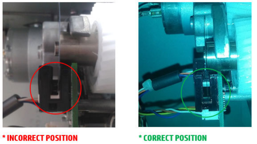
●Persistent 81:01 error codes
●Platen ngers rubbing on the roller surface, leaving black marks on the roller
●A gap in the platen beam. If there is any gap in the vertical direction between the plastic of the platen and
the metal side plate, then the chassis is damaged and the printer cannot be repaired.
If no structural damage, continue with these steps:
Call agent:
1. Check for any visible obstacles restricting the movement of the drive roller. If there is a wrinkled mass of
paper inside the paper path, lift the pinchwheels and clear the obstruction.
2. Perform the paper drive diagnostic test to troubleshoot the problem further.
Service engineer:
1. Check the connections on the engine PCA; the paper advance drive is connected to the connector labeled
Paper Motor.
2. Adjust the encoder disc and motor mount conguration using the paper advance drive installation
instructions.
3. Replace the paper advance drive.
Additional rework (Service engineer)
We have detected that some printers have bad encoder sensor PCA positioning and due to this manufacturing
issue, report SE 81:01 on the front panel.
If after reviewing the possible paper obstacles and performing the paper drive diagnostic (troubleshooting for
the call agent), the printer still shows SE 81:01, a service engineer should check the position of the encoder
sensor PCA.
As can be seen in the images above, the encoder must be positioned in the middle of the detection zone without
contacting the sensor. Wrong encoder positioning will lead the printer to SE 81:01.
156 Chapter 3 System error codes ENWW
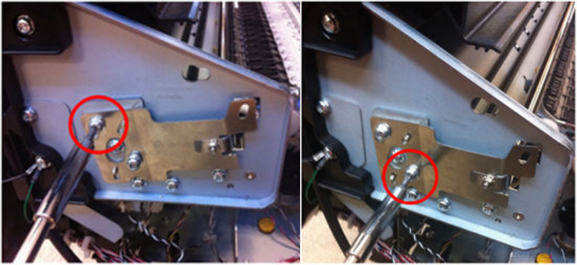
Once the issue has been detected, the service engineer should adjust the encoder correctly and the issue will be
solved.
If the encoder is correctly positioned and 81:01 is still appearing, the root cause could be another one, unrelated
to this manufacturing issue. In that case, escalate a case to GBU so that it can be thoroughly investigated.
86:01 Scan axis servo shutdown, possible paper jam
Call agent:
1. Open the window and check for any visible obstacles restricting the movement of the carriage assembly. If
there is a wrinkled mass of paper inside the paper path, lift the pinchwheels and clear the obstruction.
2. Turn o the printer and unplug the power cord. Try to move the carriage manually. Check that the cutter
disengages correctly and that the carriage is not blocked by the service station.
3. Perform the scan-axis diagnostic to obtain further information on the problem.
Service engineer:
1. Check the integrity and tension of the carriage belt. If the belt is damaged, replace it.
2. Lubricate the scan axis.
3. Perform a Encoder Strip verication and check it runs successfully.
Additional rework procedure for Service engineer:
Prior to installing Cutter X kit (CR357-67007) please manually readjust encoder strip slightly up as shown below:
1. Partially unfasten screws from Encoder Strip Spring to allow movement of it:
ENWW System error codes in full 157
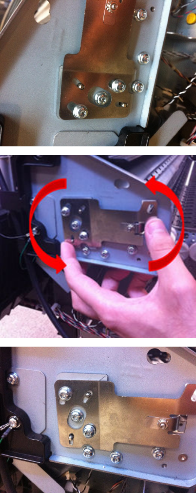
2. Slightly move Encoder Strip Spring up.
3. Tighten Encoder Strip Spring screws.
158 Chapter 3 System error codes ENWW
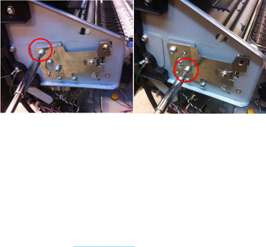
4. Launch SAX Diagnosis.
5. Launch Cutter Diagnosis.
If SE86:01 is still occurring, please readjust again.
87:01 Problem reading the scan-axis encoder (advisory)
Call agent:
1. Use the power switch at the rear to turn o the printer, then disconnect the power cord.
Reconnect the power cord, then turn on the printer.
2. Ensure that the encoder strip is clean. If it is dirty, clean it, paying special attention to the area near the
service station.
3. Replace the carriage PCA. See Engine PCA on page 314.
89:03 Stacker ramps motor error
Call agent:
1. Use the power switch at the rear to turn o the printer, then disconnect the power cord.
Remove all paper from the stacker and basket.
Reconnect the power cord, then turn on the printer.
2. Perform the stacker ramps motor diagnostic test to troubleshoot the problem further.
Service engineer:
1. Perform the Stacker Ramps Test. In the Diagnostics menu, select Stacker Ramps.
2. The product starts the Stacker Ramps PWM control test to check the subsystem. The Front Panel displays
the following messages:
a. Initializing.
b. Performing movements.
ENWW System error codes in full 159

3. Press OK to end the test and restart the product.
▲If it fails try to manually unblock the ramps. See How to manually move Stacker Ramps on page 429.
4. Check that the stacker ramps motor cable is undamaged and correctly connected to the engine PCA.
5. Replace the stacker ramps motor. See Ramps Motor on page 422.
90:03 or 90.0:03 Diverter valves motor error
Call agent:
1. Use the power switch at the rear to turn o the printer, then disconnect the power cord.
Remove all paper from the stacker and basket.
Reconnect the power cord, then turn on the printer.
2. Make sure customer has FW release MRY_03_00_xx or newer.
3. Perform the output valve test to troubleshoot the problem further.
4. Perform the output valves calibration to check system performance, and troubleshoot further.
Service engineer:
1. Check that the diverter valves motor cable is undamaged and correctly connected to the engine PCA.
2. Replace the valves motor and sensor. See Valves Motor on page 404.
3. Perform the diverter valves Service Calibration
4. If the error persists, disassemble the stacker, and perform the output valves test in order to see if the
valves are able to move without problems (ignore the result of the test). See Output Valve Test
on page 192.
5. If the valves are moving properly, replace the stacker. See Stacker on page 405.
6. Perform the diverter valves, stacker overdrive Service Calibrations.
7. Check the system, initializing the printer, and performing a "form feed and cut" action.
90.1:03 Diverter valves motor error, valves stalled in High position
Call agent:
1. Use the power switch at the rear to turn o the printer, then disconnect the power cord.
Remove all paper from the stacker and basket.
Reconnect the power cord, then turn on the printer.
2. Perform the output valve test to troubleshoot the problem further.
3. Perform the output valves calibration to check system performance, and troubleshoot further.
Service engineer:
1. Check that the diverter valves motor cable is undamaged and correctly connected to the engine PCA.
2. Perform the diverter valves Service Calibration
160 Chapter 3 System error codes ENWW

3. If the error persists, disassemble the stacker, and perform the output valves test in order to see if the
valves are able to move without problems (ignore the result of the test). See Output Valve Test
on page 192.
4. If the valves are moving properly, replace the stacker. See Stacker on page 405.
5. Perform the diverter valves, stacker overdrive Service Calibrations.
6. Check the system, initializing the printer, and performing a "form feed and cut" action.
90.2:03 Diverter valves motor error, valves stalled in Low position
Call agent:
1. Use the power switch at the rear to turn o the printer, then disconnect the power cord.
Remove all paper from the stacker and basket.
Reconnect the power cord, then turn on the printer.
2. Perform the output valve test to troubleshoot the problem further.
3. Perform the output valves calibration to check system performance, and troubleshoot further.
Service engineer:
1. Check that the diverter valves motor cable is undamaged and correctly connected to the engine PCA.
2. Replace the valves motor and sensor. See Valves Motor on page 404.
3. Perform the diverter valves Service Calibration
4. Check the system, initializing the printer, and performing a "form feed and cut" action.
93.0.n:10 Ink pressure error in rst test during in Printhead lling for color n
n indicates the failing color:
●n=0 stands for photo black
●n=1 stands for gray
●n=2 stands for matte black
●n=3 stands for cyan
●n=4 stands for magenta
●n=5 stands for yellow
Call agent:
▲If no SE 93.2.n:10 appears it means that the issue was xed after the customer reseated the printhead.
93.1.n:10 Ink pressure error in Second spitting test during in Printhead lling for color n
n indicates the failing color:
●n=0 stands for photo black
ENWW System error codes in full 161
●n=1 stands for gray
●n=2 stands for matte black
●n=3 stands for cyan
●n=4 stands for magenta
●n=5 stands for yellow
Call agent:
▲During the tube lling, the rst spitting test with the printhead failed the temperature check in color n. If no
SE 93.3.n:10 appears it means that the issue was xed after the customer reseated the printhead.
93.2.n:10 Temperature error in First test during in Printhead lling for color n
n indicates the failing color:
●n=0 stands for photo black
●n=1 stands for gray
●n=2 stands for matte black
●n=3 stands for cyan
●n=4 stands for magenta
●n=5 stands for yellow
Call agent:
1. After the customer reseated the printhead, the printer failed in the second test of ink pressure for color n.
This means that color n in the printhead might not be lled with ink, or the tubes are leaking.
2. Run primer and Ink Delivery System tests, and troubleshoot accordingly.
3. If tests run successfully:
a. Moisten tube septums with water.
b. Upgrade rmware.
c. Purge tubes again with new printhead and new supplies (60ml min per color).
93.3.n:10 Temperature error in second spitting test during in Printhead lling for color n
n indicates the failing color:
●n=0 stands for photo black
●n=1 stands for gray
●n=2 stands for matte black
●n=3 stands for cyan
●n=4 stands for magenta
●n=5 stands for yellow
162 Chapter 3 System error codes ENWW
Call agent:
During the tube lling, after the customer reseated the printhead, the second spitting test with the printhead
failed the temperature check in color n. This means that color n in the printhead is not lled with ink.
1. Depending on the colors failing the test, troubleshoot according to:
a. If colors 0-1-2 are missing, issue might be due to Service Station Side Ink Supply Station. Run Ink
delivery System test.
b. If colors 3-4-5 are missing, issue might be due to Front Panel Side Ink Supply Station. Run Ink delivery
System test.
c. If colors 0-1-3-4 are missing, issue might be with upper primer. Run primer test.
d. If colors 2-5 are missing, issue might be due to lower primer. Run primer test.
e. Any other combination of colors might point to a printhead insertion problem.Run primer and Ink
Delivery System tests and troubleshoot accordingly.
2. If tests run successfully:
a. Moisten tube septums with water.
b. Upgrade rmware.
c. Purge tubes again with new printhead and supplies (60ml min per color).
ENWW System error codes in full 163
Appendix A: How to troubleshoot system error 79:04 and 79.2:04
Introduction
The system error 79:04 is a generic rmware error (equivalent to a blue screen in Windows). It’s the system error
that the printer will display when an unknown exception occurs that cannot be identied as relating to any
specic subsystem of the printer.
Since this is a generic error, there can be multiple causes behind it. This document will cover the most probable
causes behind a system error 79:04 and will recommend the most ecient troubleshooting steps to resolve
customer issues.
It is important to mention that, although 79:04 system errors can be caused by a hardware malfunction, the vast
majority of 79:04 system errors are pure software or rmware issues. Before doing anything else, you are
recommended to try the following general-purpose solutions.
1. Update the printer’s rmware to the very latest available rmware version, even if the printer appears to be
running the latest rmware already.
2. Restore the factory settings from the front panel's Setup menu.
If these do not solve the problem, continue reading about other possible solutions below.
Possible causes
Since the 79:04 system error is a generic error, the number of possible causes behind it is large. The majority can
be grouped, however, into the following groups.
Job-related 79:04
A specic print job that is not correctly formatted for the printer or that is not correctly processed by it can trigger
a 79:04 system error.
The incorrect format or processing can come from two sources:
●Incorrect commands in the job itself. For example, a PS job with some commands that do not have the
correct PS format.
●Issues applying to the settings in the job
Symptoms
79:04 errors caused by a print job always have the same symptoms:
1. The job is received by the printer and starts to process.
2. In the middle of the processing, the printer stops and displays 79:04.
3. The printer will display the 79:04 system error again after restart. This is due to the fact that the printer will
try to reprint the job, which is pending in the queue, after restart.
4. After the second restart, the printer will start up normally
5. If the same job is sent again, it will always produce a 79:04 system error
These types of 79:04 system errors are normally caused by jobs that have been generated by 3rd party
applications (RIPs, 3rd party drivers, les exported by an application to PS, PDF, HP-GL/2, RTL, … or any
other format supported by the printer). Jobs generated by HP drivers will not normally generate 79:04
164 Chapter 3 System error codes ENWW
system errors, since the output that our drivers generate is very controlled and has been designed taking
into consideration the characteristics of our printer’s language interpreters.
There is an exception to this general rule: there are certain applications that can generate their own PS
code (Adobe PhotoShop, Adobe Illustrator, Adobe Acrobat, Corel Draw, Freehand, QuarkXpress, …). When
used with a PS driver, these applications generate the output PS themselves, instead of using the driver’s
rendering capabilities. This is known as PostScript pass-through. So, when using an HP PostScript driver
together with an application that has PS passthrough capabilities, the PS code that comes into the printer
has not been rendered by the HP driver, and, should the source le contain any PS commands that are not
correctly processed by the printer, a 79:04 system error could occur even though an HP driver is being
used.
Solutions and workarounds
When a job consistently generates a 79:04 system error, it is either because of a issue in the printer’s rmware
or because of a defect in the job itself (when it has been generated by 3rd-party software). In order to identify
the cause and nd out a solution, these issues should always be immediately escalated to the GBU through the
GCC. However, there are some workarounds and short-term solutions that can be tried in order to get the
customer up and running in the shortest possible time:
1. Send the job using a variety of dierent settings. Many times, the issue is caused by a combination of the
job contents combined with some specic setting(s).
2. If the customer is sending the le directly to the printer, try using the HP driver instead.
3. If the issue is occurring when printing through the HP PostScript driver from an application with PS
passthrough, try changing the options in the application so that it prints PS as raster (the option is typically
located in the “Advanced” options of the application’s printing dialog).
4. In some cases, there may be an unfortunate interaction between the particular job and the I/O connection
used to send that job to the printer. Try sending the same job using a print queue that uses a dierent type
of connection. For example, use a network connection instead of USB, or use the LPD network printing
protocol instead of port 9100.
Data-related 79:04
HP Designjet printers have hard disks and non-volatile memories that contain databases and les that can be
modied with user data. Some examples include:
●The printer’s queue
●The hard drive partitions that contain user jobs
●The database that stores the printer settings
●The database that stores accounting information
Some of this data is accessed by the printer at start-up, and some others are accessed as needed.
If any of this elds contains corrupt data or data with characters or values that cannot be correctly processed by
the printer, a 79:04 system error may occur.
Symptoms
There are two dierent types of symptoms for data related 79:04 system errors:
1. When the corrupt data are accessed during start-up:
ENWW Appendix A: How to troubleshoot system error 79:04 and 79.2:04 165

a. The printer will display a 79:04 during the start up process
b. Switching the printer o and on again will not solve the issue. The printer will continue displaying the
79:04 system error until the corrupt data have been cleared through a service procedure
2. When the corrupt data are accessed during normal printer operation:
a. The printer will start up normally
b. When the data are accessed (for example while printing, while navigating the queue or when
changing some settings), the printer displays a 79:04 system error
c. The printer can restart normally
d. When the data are accessed again (typically, under the same conditions as in step “b”), the 79:04
system error is displayed again
Solutions and workarounds
Data-related 79:04 errors are often resolved by means of hardware intervention. Since data are stored in
physical components (RAM, EEROM and Hard Disk), replacing these components with new ones that are empty
usually solves the problem. However, there are quicker and more eective solutions to these types of errors:
1. Clear all information that has been introduced by the user using the standard tools available in the printer.
a. Delete all jobs from the queue (from the front panel or the EWS).
b. Reset to factory defaults to clear the user’s congurations and calibrations.
c. Delete any non-standard paper preset in the printer (both the ones that have been created by the
user and the ones that have been installed as OMES proles through the EWS or the HP Utility).
2. If step 1 did not resolve the issue, you can use Service Tools to clear additional information that could be
causing the issue.
a. Start the printer in Diagnostics Boot Mode.
b. Perform an EEROM reset.
3. If step 2 did not resolve the issue, it is possible to run a recovery of the hard disk.
a. Start the printer in Diagnostics Boot Mode.
b. Perform a Hard Disk Recovery. This will erase data from the hard disk and reinstall the current
rmware. It may take up to half an hour.
4. If step 3 did not resolve the issue, you can check the hard disk's le system.
a. Start the printer in Diagnostics Boot Mode.
b. Perform a File System Check. This will x any error in the le system structure. It may take a few
minutes, or up to an hour, depending on the state of the hard disk.
IMPORTANT: It is possible that the corrupt data came to be in the printer as a consequence of some activity in
the customer’s workow. In this case, it is possible that the issue will happen again. In these cases, it is very
important to understand the sequence of events in the customer’s workow that led to the error occurring. Once
the error can be traced in the customer’s workow, escalate the issue to the GBU (through the GCC). This is done
to implement any changes in the printer’s rmware that can prevent these issues occurring again.
166 Chapter 3 System error codes ENWW

Network-related 79:04
Most HP Designjet printers have built-in networking capabilities. Network settings can be set manually, but in the
majority of cases, they are obtained automatically from the printer. These settings include many dierent elds,
such as IP address and subnet mask, available gateways, host and domain names, etc.
In some cases, there can be issues in the rmware that can cause a certain value in one of these elds to be
interpreted incorrectly, and this can lead to a 79:04 system error.
Symptoms
There is no single set of symptoms that can absolutely pinpoint a network related 79:04 system error. However,
the following guidelines can be applied:
●It can happen when the printer starts up or when accessing the Network Conguration section of the front
panel or Embedded Web Server. It can also occur apparently randomly when the printer is connected to the
network. It can also occur any time a particular network action is performed, for example when print jobs
are sent to the printer, or when connecting to the Embedded Web Server.
●In all these cases, repeating the action after restarting the printer with the LAN cable disconnected does
not cause the 79:04 error to occur.
Solutions and workarounds
In the majority of cases, these issues are due to an issue in the printer’s rmware. As soon as the conditions in
which the issue happens are understood, it should be escalated to the GBU through the GCC. However, the
following short-term solutions and workarounds can help the customer to get up and running in the shortest
possible time:
1. Disconnect the network cable in order to restart the printer and change network settings.
2. Try resetting the embedded networking settings or Jetdirect settings.
3. In the Network conguration menu in the Front Panel, disable any protocols that you are not using,
including IPv6, IPSec, SNMP and WebServices.
NOTE: Disabling SNMP or WebServices means that customers may not be able to see printer status
information; and Windows and Mac OS print-queue installers will require the user to specify the printer’s IP
address and model manually.
4. If the above steps do not work, try using a dierent type of print queue. For example, if the problems occur
when printing to a Port 9100 Socket print queue, try using the LDP protocol instead, or USB. To do this,
create a new print queue of the type required and try printing using the new queue instead.
5. If the above steps do not work and the customer is using the printer’s embedded LAN connection, try using
an accessory Jetdirect card instead. Similarly, if the customer is having problems using an EIO Jetdirect
card, try disconnecting the Jetdirect card and using the embedded networking.
In most cases, network problems that seem to occur randomly (when the printer is not being sent print jobs) are
caused by an interaction between some other devices in the customer’s network and the printer. Isolating the
printer from other devices in the network as much as possible by connecting the printer to a private network or a
dierent network subnet may help the customer continue working until the root cause of the problem is
understood and solved.
User-interaction-related 79:04
In some cases the printer may not react as expected when a certain set of conditions coincide. In these cases, if
the printer doesn’t know how to react, it may simply display a 79:04 system error and force a restart.
ENWW Appendix A: How to troubleshoot system error 79:04 and 79.2:04 167

These errors will most likely only happen in very specic corner cases that have not been identied during the
development or the qualication of the printer, so normally, they do not severely impact the customer, as they
do not aect their regular working ows.
Symptoms
●The symptoms here are as numerous as the number of possible interactions between the user and the
printer. In any case, it’s possible to identify the steps that caused the error to occur and avoid them, as the
steps will always be the same with no variance.
IMPORTANT: An major element in determining the error is what the state the printer was in at the time
the error was displayed. Actions the user has made when the printer is drying, for example, can produce an
error, whereas the same action when the printer is doing something else (or is idle) may not produce any
errors.
Solutions and workarounds
The recommended plan of action in these cases is to identify the previous steps that caused the error and:
1. Escalate the issue to the GBU through the GCC in order to have it corrected in the rmware.
2. Recommend to the customer that they try to avoid the same steps to prevent the issue
3. If the conditions that cause the error are in the customer’s regular workow, try to identify a dierent way
of achieving the same result out of the printer.
Random 79:04: Concurrence issues and memory leaks
Some 79:04 errors happen randomly when the printer is being heavily used. However, it’s impossible to nd a
single set of conditions that reproduce the problem. It just happens from time to time, without a dened pattern.
These random 79:04 can have two dierent types of root causes:
●Memory leaks: before a program is executed, it allocates the memory it will need. After the execution is
complete, the allocated memory is freed to be used by other programs. If the allocation or the release of
the memory are not properly programmed, every time the program is executed some memory will be
incorrectly labeled (either as used or as free). This is known as a memory leak. When a program with a
memory leak is executed a lot, the memory becomes progressively full (since it is not properly freed).
When the leak becomes too big, the printer is left ‘out of memory’ to execute new processes and a 79:04 is
triggered
●Concurrence issues: there are certain resources that can be accessed by multiple programs or by multiple
executions of the same program (what is known as multiple threads). Access to these resources must be
correctly controlled to prevent unexpected behavior. Issues caused by an incorrect control of these
resources are concurrence issues.
In the following you have a simple example: let’s imagine that there is a counter that controls the communication
between the Jetdirect card and the printer’s rmware. Whenever a new packet of information is sent by the
Jetdirect card to the printer, the counter increases. When the printer receives the packet and processes it
correctly, the counter decreases. Another process checks the counter from time to time to see its value and take
conclusions from it. If the counter is near 0, it means that the printer is processing correctly, and if it grows too
big, it may mean that there is a bottleneck somewhere and maybe the Jetdirect card throughput is decreased to
control its speed to the printer. However, if the access to this counter is not properly controlled, undesirable
eects may happen: in a real environment, a Jetdirect card processes thousands of information packets per
second, so this counter is updated frequently, both by the Jetdirect and the printer. If at a certain point the
Jetdirect and the printer try to access the counter at the same time and the code is not prepare to handle this, it
may happen that the Jetdirect cannot increase the counter because the printer is writing to it, and what’s worse,
168 Chapter 3 System error codes ENWW
that it does not realize this fact. If this happens a few times each second, it may happen that the counter is
decreasing faster than it’s increasing and that at a certain point it has a negative value. And then, what will the
process that is checking this counter do? Most likely, the process will not be prepared to react to a negative value
and will launch an exception that will trigger a 79:04 system error.
Symptoms
This type of 79:04 always occurs in heavy load conditions, so the symptoms will always be similar to this pattern:
●A printer that is being heavily used (printing a project or in a reprographics environment) produces 79:04
errors randomly, forcing the user to restart.
●After restarting, the printer can be used without any issues for an extended period of time, but if the
workload is consistently high, a random error will occur again.
●The error can never be associated with a specic le. The le that was being printed when the error
occurred the last time can be printed without issues after restart. And a le that has been printed without
issues several times can trigger the error in the future.
●This error is very dependant of the workow the customer has. The most common user workows have
been extensively tested both by HP and by our beta sites, so it is highly unlikely to see random 79:04
issues in these cases. These random issues tend to occur in very specic corner cases, and cannot be
reproduced unless the exact conditions of the workow are replicated. They normally happen when
sending les generated by external applications (RIPs, 3rd party drivers, etc.)
Solutions and workarounds
Random 79:04 errors are, by far, the most complex ones to diagnose and to x. The only solutions available in
these cases are:
1. Run the Hard Disk Recovery utility.
2. Identify the root cause (either in the les or in the rmware) and x it in the code, which requires the
intervention of the GBU.
3. Test any options available to modify the customer’s workow and see if any combination of them solves
the issue.
In both cases, a profound understanding of the customer’s workow is necessary. In particular, the information
that is needed is:
●Front panel settings
●Application that is being used; RIP or driver that is being used
●Application/RIP/driver settings
●Type of output les this application, RIP or driver is generating
●Some sample les that are representative of what the customer is using
●Operating system
●Method of connection to the printer
●A description of the normal ow when the issue occurs and the typical frequency of occurrence (for
instance, once every hour when sending several les non-stop, each of them with multiple copies)
You are recommended to use the Diagnostics Package to obtain this kind of information.
ENWW Appendix A: How to troubleshoot system error 79:04 and 79.2:04 169

With this information, the environment can be replicated in order to try to nd workarounds. This is also the
information that will be needed at the GBU to investigate and x the root cause of this issue once it is escalated.
Hardware-related 79:04
Hardware is, by far, the least likely cause of a 79:04 system error. Replacing hardware components does not
normally x the issue and increases the total turn around time in nding a workable solution.
In some cases, a failure in a component in the printer’s electronics may cause a 79:04 system error, since the
printer’s electronics are involved in the execution of the rmware and the processing of jobs. It needs to be
noted, however, that hardware failures in the electronics tend to produce specic system errors that point
directly to the component that is failing.
Some hardware problems that could cause the 79:04 error are:
●Defective clusters on the hard disk. If these clusters are used to execute the rmware or to process a job,
they may produce a 79:04. It needs to be noted however, that most 79:04 errors that are resolved by an
hard disk replacement are in fact, data related 79:04 errors that could have been solved more eciently
and quickly following the other steps.
●Defective memory segments. If the RAM memory has some defective segments, a 79:04 may occur when
these segments are used.
●Intermittent defects in the electronic components that are involved in the processing of a job: carriage PCA,
trailing cable, formatter, and engine PCA. This is a highly unlikely cause, since defects in these components
will produce subsystem specic errors.
Symptoms
There’s no single set of symptoms behind hardware-related 79:04 system errors. The most usual ones, however
are:
●79:04 during startup. Restarting the printer may or may not solve the problem
●79:04 while processing or printing a job. Restarting the printer and printing the same job does not always
produce the error.
Solutions and workarounds
In the following procedure perform each step as it appears in the list and only move on to the next step once you
are sure the 79:04 error has not been cleared:
1. Restart the printer in Diagnostics Boot mode and execute the service tests to validate the functionality of
all the electronics components.
●Perform the troubleshooting for “data related 79:04” system errors, refer to Appendix A: How to
troubleshoot system error 79:04 and 79.2:04 on page 164.
2. Replace the hard disk drive.
3. Replace the replace the formatter.
4. Escalate the issue before replacing any additional parts.
170 Chapter 3 System error codes ENWW

Troubleshooting based on symptoms
This section describes which troubleshooting steps to perform for a 79:04 system error based on the symptoms
of the issue. Perform each step as it appears in the list and move on to the next step only once you are sure the
79:04 error has not been cleared.
Front panel displays 79:04 at startup
1. Restart the printer twice. If the system error has been caused by a job because it is in an incorrect format,
restarting twice will clear the error (the rst time after restart, the printer will attempt to print the job again,
and this will cause the error to reoccur). If restarting the printer twice solves the issue, then it is an issue
related to the job and you should refer to the section on a Job Related SE79:04.
2. Upgrade the printer’s rmware. Even if the currently installed rmware version is the latest one, re-install
it. Since the printer cannot start normally, you will need to upgrade the rmware while restarting the
printer in Diagnostics Boot Mode. For this, a special le and a special upgrade process will be needed. For
more information, see Appendix B: Updating rmware in boot mode on page 176 .
3. Disconnect the network cable and restart the printer. If this solves the problem, then it is a network related
79:04 and you should follow the guidelines for this type of 79:04.
4. Remove all cartridges, printheads and printhead cleaners (if available). Unload the paper. Restart the
printer. If the printer can start normally, insert the consumables one by one until you isolate the one that is
causing the error. Do not insert any of the replaced consumables in another printer
5. Restart the printer in Diagnostics Boot Mode and perform the “Electronics test”. If an electronic component
is identied as faulty, replace it.
●Restart the printer in Diagnostics Boot Mode and Reset the EEROM. If the issue is solved by this, this is
a data-related 79:04 system error and you should follow the guidelines for this type of error.
6. If the unit has been used for some time and suddenly has started to show this behavior, replace the hard
disk drive.
7. If the issue is new and the issue happens since the rst startup, do not replace the hard disk drive.
8. If none of the previous steps solved the issue, escalate the issue with the following information:
●Unit information: S/N, P/N, accessories
●Conditions where the problem occurs and conditions prior to the rst occurrence of the problem
●The results of the previous 8 steps
●The System Error detailed information (this can be obtained by pressing CANCEL + Down)
●In order to obtain the diagnostic package, see Appendix C: Obtaining the diagnostics package
on page 177.
Front panel displays 79:04 during printer operation, not while sending jobs
1. Restart the printer.
2. Upgrade the printer’s rmware. Even if the currently installed rmware version is the latest one, re-install
it.
3. Reset the printer to factory defaults
4. In order to narrow the scope of the issue, try the following:
ENWW Appendix A: How to troubleshoot system error 79:04 and 79.2:04 171

a. Disable the queue.
b. Disable any unused network protocols.
c. Disable SNMP and WebServices (if they are available in the printer.
d. Disable “Sleep mode” from the Service Utilities menu.
e. Delete any paper presets that you may have uploaded or created using the printer's
spectrophotometer.
5. Restart the printer in Diagnostics Boot Mode and perform the “Electronics test”. If an electronic component
is identied as faulty, replace it.
6. Restart the printer in Diagnostics Boot Mode and Reset the EEROM. If the issue is solved by this, this is a
data-related 79:04 system error and you should follow the guidelines for this type of error.
7. Format the hard disk drive. To do so, you will need to start the printer normally, enter the Service Utilities
menu and then the Secure Disk Erase option. Set the Erase method to “Fast Erase” and then perform the
disk erase process. This will take 45–75 minutes and will erase all user information from the disk, resolving
any issue caused by corrupt data. After the erase process, a rmware update will be required. If this solves
the issue, this is a data-related 79:04 system error and you should follow the guidelines for this type of
error.
8. Try to identify the combination of settings or actions that led to the system error and try to reach the same
result with a dierent combination. Escalate the issue to x the original problem.
9. If none of the previous steps could solve the issue, escalate it with the following information:
●Unit information: S/N, P/N, accessories
●Conditions where the problem occurs and conditions prior to the rst occurrence of the problem
●The result of the previous 8 steps
●The printer information pages (either printed and faxed or obtained through the Embedded Web
Server)
●The System Error detailed information (it can be obtained by pressing CANCEL + Down)
●In order to obtain the diagnostic package, see Appendix C: Obtaining the diagnostics package
on page 177.
Front panel displays 79:04 while printing a single job
The error happens after a single job is sent. It’s easy to identify which job that has produced the error, since every
time that this same job is sent, the error is replicated.
1. Restart the printer twice (after the rst restart, the printer will show the 79:04 system error again, since the
printer will attempt to reprint the last job in the queue, which is the one that caused the issue)
2. If you are using an HP driver, update the driver to the latest version
3. Upgrade the printer’s rmware. Even if the currently installed rmware version is the latest one, re-install
it. Send the job using dierent print settings. The following ones can be helpful:
a. Try sending the job without selecting a paper prole in the driver
b. Try changing the Image Quality settings
172 Chapter 3 System error codes ENWW

c. If you are using the HP-GL/2 driver, try the option “Send job as bitmap”
d. If you are using the PS driver, try using the HP-GL/2 driver instead
e. If you are using the PS driver from an Adobe application (or any other application that can handle PS),
try changing the application’s print settings so that the PS is generated as Raster.
4. Try the following front panel settings:
a. Change the Print Language option from “Automatic” (which is the default setting) to the language
that is being printed (PS, HP-GL/2, …)
b. Queue = OFF
c. Start Printing = After processing
d. For PS SKUs, try changing the encoding setting (“Automatic” by default) to Binary or ASCII
5. If you are using a 3rd-party application that does not print through the HP driver, try modifying the printing
workow by:
a. Using an HP driver
b. Changing the settings in the application’s printing dialog
6. If you are using an accessory Jetdirect card, try using the internal network connector or USB (if available).
7. Escalate the issue, providing the following information:
●Unit information: S/N, P/N, accessories
●Conditions where the problem occurs and conditions prior to the rst occurrence of the problem.
●The result of the previous 7 steps
●The printer information pages (either printed and faxed or obtained through the Embedded Web
Server)
●The system error detailed information (it can be obtained by pressing CANCEL + Down)
●Information on the workow:
–Operating system
–Application
–Driver
–Settings in the driver and the application
–Settings in the printer
–Connection method and settings
The original le along with the information on how to reproduce the issue
A print to le that can reproduce the issue
●In order to obtain the diagnostic package, see Appendix C: Obtaining the diagnostics package
on page 177.
ENWW Appendix A: How to troubleshoot system error 79:04 and 79.2:04 173
Random 79:04 during continuous printing
The error does not happen with a single job. It happens randomly during continuous printing, normally while the
printer is managing a heavy load (printing a project or in a reprographics environment).
This type of error is caused either by memory leaks or by concurrence issues in the printer’s rmware. They
normally happen in unusual environments in which these memory leaks or concurrence issues that have not
been detected during qualication have occurred. These issues cause the printer to crash at a completely
random moment during printing, and are not associated to a specic job.
Because of this, troubleshooting these issues is normally quite complex.
1. Restart the printer twice (after the rst restart, the printer will show the 79:04 system error again, since the
printer will attempt to reprint the last job in the queue. If the issue continues occurring randomly, continue
troubleshooting
2. If you are using an HP driver, update the driver to the latest version
3. Upgrade the printer’s rmware. Even if the currently installed rmware version is the latest one, re-install
it.
4. Try restoring the factory default settings from the printer's front panel.
5. Try the following changes in the workow:
a. Change the Print Language option in the Front Panel from “Automatic” (which is the default setting) to
the language that is being printed (PS, HP-GL/2, …)
b. Queue = OFF
c. Start Printing = After processing
d. For PS SKUs, try changing the encoding setting (“Automatic” by default) to Binary or ASCII
e. If you are using the HP-GL/2 driver, try sending the job as a bitmap
6. If you are using a 3rd-party application that does not print through the HP driver, try modifying the printing
workow by:
a. Using an HP driver
b. Changing the settings in the application’s printing dialog
7. Escalate the issue with the following information:
●Unit information: S/N, P/N, accessories
●The printer information pages (either printed and faxed or obtained through the Embedded Web
Server
●The system error detailed information (it can be obtained by pressing CANCEL + Down)
●Information on the workow:
–Operating system
–Application
–Driver
–Settings in the driver and the application
174 Chapter 3 System error codes ENWW

–Settings in the printer
–Connection method and settings
●Exact information on how to replicate the environment that reproduces the issue, including some
example les that can be sent to the printer to replicate a heavy load environment. These les will
need to be:
–Original application les, if the issue happens printing from an application through our driver
–Print to les if the issue happens printing from a 3rd-party application
●Information on the approximate frequency of the occurrence of the issue
●In order to obtain the diagnostic package, see Appendix C: Obtaining the diagnostics package
on page 177.
ENWW Appendix A: How to troubleshoot system error 79:04 and 79.2:04 175
Appendix B: Updating rmware in boot mode
If the printer is displaying a 79:04 system error during start up and will not start normally, then services like the
Embedded Web Server will not work.
If it is not possible to perform a rmware upgrade using the normal procedures (for instance, if there is a System
Error and the Embedded Web Server is unavailable), it is possible to perform an emergency rmware upgrade
using a USB ash drive. Follow these steps:
1. Copy a valid FMW rmware le onto a USB ash drive. This le is provided in HP Designjet Online. Remove
all other contents from the ash drive.
2. Turn o the product.
3. Connect the USB ash drive to the USB host port in the front panel.
4. Turn on the product, and follow the front panel instructions.
176 Chapter 3 System error codes ENWW

Appendix C: Obtaining the diagnostics package
Printers keep an internal log of their own actions. When a system error occurs, the diagnostic package may help
to nd the cause and the solution. By default, whenever it restarts, the printer deletes the current log and starts
a new one, in order to avoid using a lot of hard disk space.
There are three types of diagnostic package:
●Diagnostic package (reduced level)
●Extended diagnostic package (medium level)
●Extended diagnostic package from USB (verbose level)
There are two ways of retrieving the information:
●From the front panel with a USB ash drive (all levels)
●From the Embedded Web Server (reduced or medium level)
NOTE: If the extended diagnostic package is available, it will be visible from the Embedded Web Server.
When the information has been obtained, it should be attached to the customer case.
NOTE: The extended diagnostic package enabled from USB is always preferred as it includes extra level
logging.
NOTE: Once the case is solved, the extended diagnostic package must be disabled in order to preserve disk
space.
Front panel USB method
This method works only with a standard USB ash drive (without a ash drive, use the Embedded Web Server
method). The Front Panel USB method has the advantage of working with very minimal printer functionality: just
the printer OS and the USB connection. It can work without connectivity and the front panel. The level of logging
is more detailed than the extended package that can be enabled from EWS. It is recommended to use the USB
method whenever possible.
1. Take a standard USB ash drive, formatted as FAT32.
2. Create an empty le in the USB ash drive (right-click, New > Text Document) and name it
pdipu_enable<action code>.log. You can also nd these les attached to this document.
Empty le to load in the USB Actions
pdipu_enable_elog.log
pdipu_enable_scanner_elog.log
Enable verbose logging. Printer needs to restart to take eect.
The le with “scanner” allows to enable logs for the scanning
subsystem in T2500 and T3500.
pdipu_enable_loggz.log Extract the logs to the USB. After downloading check the size. If
it’s 0KB try downloading with another USB key.
pdipu_enable_loggz_dlog.log
pdipu_enable_scanner_dlog.log
Disable the verbose logging. It is important to run this after the
case is solved to prevent the disk getting full from logs. The le
with “scanner” works for the T2500 and T3500 scanning
subsystem.
3. The recommended ow to get an extended diagnostic package through USB is:
ENWW Appendix C: Obtaining the diagnostics package 177
a. Create an empty le called “pdipu_enable_elog_loggz.log” and copy it in a USB ash drive.
b. Plug in the USB and switch on the printer. You will hear the message “Traces are now enabled. You
must reboot the printer”. Unplug the USB and reboot the printer.
c. After reboot, reproduce the issue.
d. Plug again the USB. You will hear the message “Generating diagnostic package, please wait” “You can
now detach the USB pen drive”
e. The extended diagnostic package has been saved in the USB. Copy it into your computer.
f. To disable the logs, erase the information stored previously into the USB, create an empty le caller
“pdipu_enable_dlog.log” and plug it into the printer.
4. The printer gives audio messaging detailing the progress. The audio messages available are:
a. “Generating diagnostic package, please wait.”
b. “Diagnostic package successfully complete”
c. “Error. Diagnostic package failed”
d. “You can now detach the USB pen drive”
e. “Traces are now enabled. You must reboot the printer”
f. “Generating package without printer.log”
g. “Encrypting package”
Embedded Web Server method
▲Access the Embedded Web Server by typing the IP address of the printer in a Web browser. In the Support
tab, click Service support to display the following page.
If the problem persists and is dicult to debug, try the extended diagnostics package. To enable the
extended diagnostics package, click Enable the extended diagnostics package. The printer needs to be
restarted after enabling or disabling the extended diagnostics package.
At any time after enabling the extended diagnostics package, you can download the package and the
printer logs by clicking Download the extended diagnostics package.
When you have nishing using the extended diagnostics package, remember to disable it; otherwise it
could aect printer performance or cause undesirable side-eects.
178 Chapter 3 System error codes ENWW


Introduction
This chapter explains how to use the product's diagnostic tests and utilities, and what to do in the event of any
failure.
NOTE: If possible, always perform a diagnostic test on a component that you are about to replace, to make
sure that is the component that has failed. If the test on that component passes, there is no need to replace it.
Initialization Self Test
Initialization sequences
Whenever the product is switched on, it automatically performs a series of internal self-tests and mechanical
initialization sequences. If any part fails, a system error will appear and you should consult System error codes
on page 115.
Auto-Diagnostics Test
In the event of a paper or scan-axis jam triggering a system error 86:01, a message will appear on the Front
Panel.
After restarting, the product will exercise several electromechanical subsystems involved in Paper or Scan Axis
movement. If necessary, you may be asked to move the carriage manually or check whether the main roller is
moving. You may also be asked to launch an Auto-Diagnostics Test.
●In the event of a paper jam, if another paper jam occurs during the rst 15 paper advance movements after
the product restarts, the product will ask you to launch the Paper Axis Auto-Diagnostics.
●In the event of a scan-axis jam, if another scan-axis jam occurs during the rst 50 carriage movements
after the product restarts, the product will ask you to launch the Scan Axis Auto-Diagnostics.
A nal result will be shown with all the collected data.
Phone Support
NOTE: In certain circumstances, a Call Agent can try to troubleshoot the product by requesting the customer to
perform a Service Test over the phone. Using this process, it can be determined whether the product requires
any on-site maintenance.
Remember that the key combination for the customer to enter the Service Tests and Utilities is the same as the
one that the engineer will use.
180 Chapter 4 Diagnostics, Service Utilities and Calibrations ENWW

Diagnostic Tests and Utilities
The following is a list of all diagnostic test and utilities available in the product. For instructions on entering the
Diagnostics menu, see Entering the Diagnostics Menu when booting the printer on page 183.
+ Scan Axis Test on page 183
Star-wheel lifter
PRS
Scan axis
Cutter
Paper Drive Test on page 186
Electronics Module Test on page 187
Carriage Assembly Test on page 188
Sensors Test on page 191
Stacker Empty Sensor Test on page 191
Output Valve Test on page 192
Output Valve Calibration on page 192
Pinches Lifter Test on page 194
Stacker Ramps Test on page 194
Stacker Overdrive Test on page 195
Stacker Jam Sensor Test on page 196
Stacker Capacity Sensor Test on page 196
+ Ink Delivery System (IDS) Test on page 196
Ink Delivery System
Check ink supplies
Check leakage
+ Service Station Test on page 199
Service station
Primers
Enable I/O Interfaces Utility on page 200
Unit Information Utility on page 200
EEROM Reset Utility on page 200
Front Panel Lock Reset on page 201
Hard Disk Recovery on page 201
File System Check on page 201
Enable Special Margin on page 201
Set margin on page 201
Enable HP-GL/2 palette options on page 202
ENWW Diagnostic Tests and Utilities 181

Content thresholds on page 202
Stacker ramps test on page 202
Set I/O factory defaults on page 203
Entering the User Diagnostic Menu
1. Go to the printer’s Main Menu.
2. Go to the Diagnostics Menu.
3. Type the code “1714.”
4. Go to Diagnostic Tests.
5. Allow the printer to reboot.
Printer will remain in “User Diagnostics Menu” until it is setup to go back to Printer mode.
To go back to Printer mode:
1. From “User Diagnostics Menu” go to “Reboot in printer mode.”
2. Allow the printer to reboot.
The “User Diagnostics Menu” has a limited set of Diagnostics and allows one to perform only the following
actions:
●Scan Axis Test on page 183
●Paper Drive Test on page 186
●Electronics Module Test on page 187
●Sensors Test on page 191
●Stacker Jam Sensor Test on page 196
●Stacker Capacity Sensor Test on page 196
●Stacker Empty Sensor Test on page 191
●Output Valve Test on page 192
●Pinches Lifter Test on page 194
●Stacker ramps test on page 202
●Stacker Overdrive Test on page 195
●Ink Delivery System (IDS) Test on page 196
●Service station on page 199
●Enable I/O Interfaces Utility on page 200
●Unit Information Utility on page 200
182 Chapter 4 Diagnostics, Service Utilities and Calibrations ENWW

Entering the Diagnostics Menu when booting the printer
1. Make sure the product is switched o with the Power key on the side of the Touch Screen Panel, and not
with the power switch on the back of the product.
2. Press and release the Power key to switch on the product.
3. Wait for the Home button to come on.
4. Press the Home button; the button acknowledges by ashing.
5. All LED come on. Press and release them, one after another:
●The Cancel icon
●The Home icon
●The Help icon
NOTE: Do not push the icons all at the same time, push each one in the order shown above and release
each icon before pressing on the next icon.
6. The 6 buttons on the Front Panel will then blink twice; then wait until the product completes the
initialization sequence and shows the Diagnostics menu.
7. In the Diagnostics menu scroll up and down sliding the nger vertically on the Front Panel and press on the
desired option.
NOTE: The Diagnostic Tests and Utilities work in a special mode that does not require the full initialization of
the product. Therefore, whenever you have nished a test, you must power o the product and power on again
before trying to print or before executing another test.
NOTE: In some cases a quick press of a button may not be recognized by the product. When pressing a button,
be sure to press it deliberately for about 1 second.
NOTE: If the product hangs up during a test, switch the product o and restart from step 1.
Scan Axis Test
The complete Scan Axis test consists of individual tests for the dierent components related to the Scan Axis.
The subsystems included in this assembly are:
●Star Wheel Lifter
●Automatic PRS Adjustment.
●Scan Axis Servosystem
●Cutter
You must perform the Scan-Axis Test after:
●System Error Code 42:XZ.
●System Error Code 47:XZ.
●System Error Code 73:XZ.
ENWW Diagnostic Tests and Utilities 183

●System Error Code 87:XZ.
●System Error Codes related to Scan-Axis shutdown or Carriage jam.
Diagnostic tests also need to be performed after removing or replacing certain product components. If you have
removed or replaced product components, check the user guide to see which tests and calibrations you need to
perform.
CAUTION: ALL THE COVER SENSORS ARE DISABLED WHEN IN THE SERVICE TESTS MENU. IF THE CARRIAGE IS
MOVING IT WILL NOT STOP IF THE SCANNER IS OPEN, SO BE VERY CAREFUL NOT TO PUT YOUR HANDS INSIDE.
NOTE: IF POSSIBLE, ALWAYS PERFORM THIS TEST BEFORE REPLACING ANY COMPONENT OF THE SCAN-AXIS.
Star Wheel Lifter test
The Star Wheel Lifter subassembly is designed to move the Star Wheel support to the up and down positions.
This is used to load roll or sheet paper and avoid damage to the Star Wheel caused by paper jams etc.
Perform the Scan Axis - Star Wheel Lifter test as follows:
NOTE: Perform this test with the Printheads and the Tubes System installed in order to get values that can be
compared correctly.
1. In the Diagnostics menu, select Scan Axis .
2. The Front Panel will display a screen, select Star Wheel Lifter.
If there is a failure at any point during the tests, the Front Panel will display the relevant System Error Code.
To troubleshoot any displayed error codes, see System error codes on page 115.
3. The product then starts the Star wheel lifter PWM control test to check the subsystem. As the test executes
the Front Panel displays the following messages:
●Initializing
●Checking movement
●Testing…
4. The Front Panel displays the test results and prompts you to continue by ending the test and restarting the
product.
PRS Test
The PRS subsystem is designed to move the carriage assembly between two predetermined vertical positions
with respect to the plane of the print platen. This allows dierent papers of dierent thicknesses to be used
without losing print quality.
Perform the Scan Axis - PRS test as follows.
NOTE: Perform this test with the Printheads and the Tubes System installed in order to get values that can be
compared correctly.
1. In the Diagnostics menu, scroll to Scan Axis and press on this menu option.
2. The Front Panel will display a screen, select PRS.
184 Chapter 4 Diagnostics, Service Utilities and Calibrations ENWW

3. In the Scan Axis submenu, scroll to PRS and press OK to start the test
The product will start the Scan Axis subsystem Common Initialization and PRS test initialization. If there is a
failure at any point during the tests, the Front Panel will display the relevant system error code. To
troubleshoot any displayed error codes, see System error codes on page 115.
4. The product then starts the PRS test to check the subsystem. As the test executes, the Front Panel displays
the following messages:
●Initializing
●Checking movement
5. Once the test has completed, the Front Panel prompts you to conrm that the PRS moved.
6. If the PRS moved, press OK to accept the results. If the PRS did not move, press Cancel to reject the results
and exit the test.
7. Press OK to end the test and restart the product.
Scan Axis Test
The Scan Axis subsystem is designed to move the carriage assembly between two predetermined horizontal
positions with respect to the plane of the print platen. This allows papers of dierent widths to be used without
losing print quality.
Perform the Scan Axis - Scan Axis test as follows:
NOTE: Perform this test with the Printheads and the Tubes System installed in order to get values that can be
compared correctly.
1. In the Diagnostics menu, select Scan Axis.
2. The Front Panel will display a screen, select Scan Axis.
3. The product checks the Scan Axis motor. The Front Panel displays the following messages:
●Initializing
●Checking motors
4. Depending on the results of the tests, you may be asked to perform the following operations.
a. Open the main window.
b. Manually move the carriage to another position. The carriage should not oer resistance to manual
movement. Do not force any product part while moving the carriage. The Front Panel will show a text
describing the action and an animation as an example of the requested operation. Press OK when you
have nished moving the carriage.
c. Close the main window.
5. Afterwards, the test will automatically continue checking for possible Scan Axis errors. The carriage will
move automatically along the Scan Axis several times, taking a few minutes. As the test executes, the
Front Panel displays the following messages:
ENWW Diagnostic Tests and Utilities 185

●Checking paper jam
●Checking movement
●Checking life counters status
6. If the Scan Axis passes the test, the Front Panel displays a message, otherwise it displays an error code.
Press OK to continue.
Cutter test
The Cutter is designed to cut roll paper after printing to the dened sheet size. Before executing this test you
should run the Scan Axis, Media Drive and Carriage tests to ensure that each of these subsystems is operating
correctly.
Perform the Scan Axis - Cutter test as follows.
1. In the Diagnostics menu, select Scan Axis.
2. The Front Panel will display a screen, select Cutter.
3. A screen is displayed, check that the paper is unloaded and all the covers are closed, and select OK.
If there is a failure at any point during the tests, the Front Panel will display the relevant system error code.
To troubleshoot the displayed error code, see System error codes on page 115.
4. A is displayed. With the Media Lever lowered, feed a roll of paper (not a sheet) into the paper path until it
reaches the product roller. Then press OK to continue.
If you have not fed enough paper into the product, the diagnostic will show a message saying that the
paper was not detected and the test will fail and the product will reboot. In this case, try again, taking care
to feed more paper. If the problem continues, check that the sensors are working correctly. If necessary,
perform the Sensors Test (see Sensors Test on page 191).
5. The product then starts an actual test cut of the paper. As the test executes the Front Panel displays the
following messages:
●Advancing paper
●Preparing cutter
●Cutting paper
●Disengaging cutter
6. Once the test has completed the Front Panel displays the test result and prompts you to conrm that the
cutter worked.
7. Press OK if the cutter worked or Cancel if the cutter did not work.
8. Press OK to end the test and restart the product.
Paper Drive Test
The Paper Drive test diagnoses failures of components of the Paper Axis.
You must perform the Paper Drive Test after:
186 Chapter 4 Diagnostics, Service Utilities and Calibrations ENWW

●System Error Code 81:XZ.
●System Error Code 41:XZ.
●System Error Code 73:XZ.
Diagnostic tests also need to be performed after removing or replacing certain product components. If you have
removed or replaced product components, check the user guide to see which tests and calibrations you need to
perform.
CAUTION: ALL THE COVER SENSORS ARE DISABLED WHEN IN THE SERVICE TESTS MENU. IF THE CARRIAGE IS
MOVING IT WILL NOT STOP IF THE SCANNER IS OPEN, SO BE VERY CAREFUL NOT TO PUT YOUR HANDS INSIDE.
NOTE: IF POSSIBLE ALWAYS PERFORM THIS TEST BEFORE REPLACING ANY COMPONENT OF THE MEDIA-AXIS.
Perform the Paper Drive test as follows:
NOTE: Perform this test with the Printheads and the Tubes System installed in order to get values that can be
compared correctly.
1. In the Diagnostics menu, select Paper Drive.
2. The Front Panel displays a screen, select OK to continue with the process. Unload paper if loaded, and
select OK again.
3. The Front Panel then displays the Analog Encoder calibration results.
The GAIN for channels A and B should be lower than 5.
4. If the results are correct, press OK to accept the results. If the results are not correct, press Cancel to reject
the results and fail the test.
5. If you accept the results, the Front Panel will continue with the tests. It will ask you to press OK to continue
with the process. When prompted, unload paper if any is loaded.
6. The Front Panel then displays the test results.
●The rst PWM avg result (forward move) should be between 7700 and 10560 and the second Pwm
avg (backward move) between 7600 and 10450.
●The rst Speed error result should be no more than 78.65 and the second no more than 112.5.
●The rst PWM StDev result should be no more than 162.5 and the second no more than 187.5.
●The rst PWM max result should be no more than 12250 and the second no more than 12125.
7. If the results are correct, press OK to accept the results. If the results are not correct, press Cancel to reject
the results and FAIL the test.
8. If you accept the results, the Front Panel shows a screen, press OK to nish.
Electronics Module Test
This diagnostic test gives information about the electronics. Several modules can be tested, and the user is
asked whether he want’s to test each specic module.
ENWW Diagnostic Tests and Utilities 187
1. In the Diagnostics menu, select Electronics Module.
2. Engine Board Module: The Front Panel then prompts you to test the Engine Board, press OK to run the test,
CANCEL to skip it. It checks the presence of the required devices in the Engine Board. If the board is OK, 4
Hannibal devices should be listed ( from Hannibal1 to Hannibal4).
3. Power Supply Module: This test checks the correct function of the E-Box Fans.
4. The Front Panel then prompts you to test the Power Supply, press OK to run the test, CANCEL to skip it.
5. If the fans are working properly, the test displays: PSU fan status; OK
6. Formatter Module: The purpose of this test is to diagnose a failure in the operation of the Formatter. The
Front Panel then prompts you to test the Formatter, press OK to run the test, CANCEL to skip it.
The information shown in the Front Panel is:
●The memory size
●Type and size of the partitions on the Hard Disk
●Size and percentage used of the data and boot partitions on the Hard Disk
Carriage Assembly Test
The Carriage Assembly test diagnoses failures of any components of the Carriage. This test should be run in any
of the following circumstances.
●Before replacing the Carriage Assembly.
●After removing or replacing certain product components. If you have removed or replaced product
components, check the user guide to see which tests and calibrations you need to perform.
●If printhead alignment fails repeatedly.
●If, when loading paper, the search for the edge of the paper fails repeatedly.
●If no printheads are detected (check more than one).
●If the system error message 02.1:10 appears.
If an error is detected during the test, the Front Panel will display an error code and message. The test will not
continue after that point.
1. To execute the Carriage Assembly diagnostic, select the “Carriage Assembly” option in the diagnostic menu
and press OK.
2. The diagnostic starts testing the subsystem. After a time a message appears: Initializing, Getting
information, or Checking voltages; this indicates that the diagnostic test is in progress.
188 Chapter 4 Diagnostics, Service Utilities and Calibrations ENWW
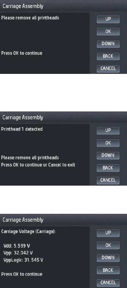
3. A message appears asking to remove the printheads. Open the printer window, open the carriage latch,
remove the printheads from the carriage. Close the carriage cover, printer window, and press the OK
button.
If the printheads were not correctly removed after pressing the OK button, a message appears asking to
remove them. To do so, repeat the previous steps. If the printheads were correctly removed (it is clear
there are no printheads installed in the carriage), and the message still appears, press the Cancel (X) key;
the test will nish, and the appropriate error code will appear.
4. Once all the printheads are removed, some additional parameters are checked and their values and/or
ranges are displayed in the front panel:
ENWW Diagnostic Tests and Utilities 189
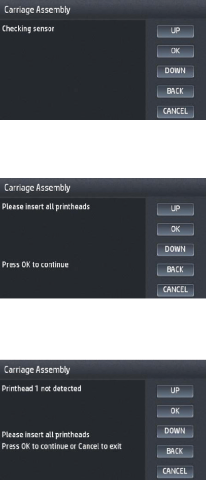
5. The diagnostic test will check the carriage LEDs and sensors. This can take some minutes. The following
message appears in the front panel:
6. After the line sensor has been checked, you’re asked to insert the printheads again. To do so, open the
printer window, open the carriage cover, and insert the printheads into the carriage. Then, close the
carriage cover, printer window, and then press OK.
If the printheads were not correctly installed after pressing the OK button, a message appears asking to
install them. To do so, repeat the previous steps. If on checking, the printheads were correctly installed (it is
clear there are printheads installed in the carriage), and the message still appears, press the Cancel (X) key;
the test will nish, and the appropriate error code will appear.
190 Chapter 4 Diagnostics, Service Utilities and Calibrations ENWW

7. After installing all printheads, more checks take place, if everything was is correct, the following message
appears:
If an error has been found in any of the steps of this diagnostic (parameter values are out of the allowed
range; printhead improperly detected or not detected, sensor errors, etc.) the diagnostic test will
automatically detect it and stop the test (checks will stop), and the error description will be shown in the
front panel. The error description will contain the System Error code (for determining the recovery action)
and the specic error cause, if known.
Sensors Test
The Sensors test diagnoses failures of any sensors of the product. Always run this test before replacing any of
the following sensors:
●Window Position sensor
●Upper or lower roll cover sensor
●Stacker arm sensor
Diagnostic tests also need to be performed after removing or replacing certain product components. If you have
removed or replaced product components, check the user guide to see which tests and calibrations you need to
perform.
1. In the Diagnostics menu, scroll to Sensors and press on this menu option, press OK to start the test.
2. The Window Position sensor test starts and the Front Panel prompts you to open the Window cover.
Open the Window cover, and press OK to continue.
NOTE: Make sure that no object is interfering with the sensor.
3. The Front Panel prompts you to close the Window cover, and the sensor, on detecting the cover closing.
Close the Scanner and press OK to continue.
4. Follow the same procedure for the Roll 1, Roll 2, and the Stacker Cover.
5. When the tests are complete, the Front Panel displays a nal message. Press OK to shutdown.
Stacker Empty Sensor Test
The stacker empty sensor test diagnoses failures of the stacker empty sensor. This test checks the connectivity
and the proper operation of the sensor.
1. In the diagnostic menu select Stacker empty sensor. The printer will take a while to verify the sensor
connectivity. If the sensor is not connected, on the Front Panel the following code appears; 53.6:10, and
ENWW Diagnostic Tests and Utilities 191

the message “Stacker empty sensor connectivity failure”. Press OK to continue and return to the diagnostic
menu.
2. If the sensor is connected, the test asks to place a paper to cover the stacker sensor, do so, then press OK
to continue, or Cancel to exit.
3. After putting the paper and pressing OK, the test will ask you to remove it and select between OK or Cancel.
4. If during the two steps described above the test detects a non proper operation, the Front Panel displays
the following error code; 53.6:10, and the message “Stacker empty sensor fails to detect paper”. In this
case make sure that there are not objects covering the sensor and repeat the test.
Output Valve Test
Perform the Output Valve test as follows:
NOTE: Perform this test with the printheads and the tubes system installed in order to get values that can be
correctly compared.
1. In the Diagnostics menu, select Output Valve.
2. The product starts the Output Valve PWM control test to check the subsystem. As the test executes the
Front Panel displays the following messages:
●Initializing
●Performing movements
If there is a failure at any point during the test, the Front Panel displays the relevant System Error Code. To
troubleshoot any displayed error codes, see System Error Codes.
3. Press OK to end the test and restart the product.
Output Valve Calibration
The purpose of this Service Calibration is to calibrate the valve that directs the print to the stacker or basket.
This valve also detects output jams to the basket by performing several movements to see if there’s any paper
obstruction.
It has to be done when:
●Reinstalling or replacing the complete stacker.
●When reinstalling or replacing the diverter - cutter platen assy.
●When replacing the output valve motor.
Follow these steps:
1. Prior to calibration; remove all the prints from the stacker and basket, and also any paper loaded in the
printer.
192 Chapter 4 Diagnostics, Service Utilities and Calibrations ENWW
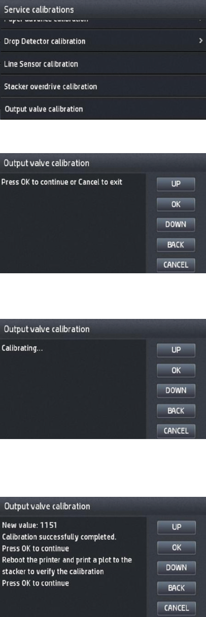
2. To select this calibration, go to 'output valve calibration':
3. The screen will show the 'calibrating status' during some minutes, while the output valve is performing
some movements.
4. At the end of the process, you will have the result of the calibration. The screen will show also a
recommendation to verify the calibration (print a plot to stacker). Typical values for the calibration range
from 1015 to 1225.
ENWW Diagnostic Tests and Utilities 193

5. By pressing OK in the next screen, the printer will shut down automatically.
6. Power – on the printer, and print (for example a Drawing Demo print) to the stacker, to verify the success of
the calibration.
Pinches Lifter Test
Perform the Pinches Lifter test as follows:
NOTE: Perform this test with the printheads and the tubes system installed in order to get values that can be
correctly compared.
1. In the Diagnostics menu, select Pinches Lifter.
2. The product starts the Pinches Lifter PWM control test to check the subsystem. As the test executes the
Front Panel displays the following messages:
●Initializing
●Performing movements
If there is a failure at any point during the test, the Front Panel displays the relevant System Error Code. To
troubleshoot any displayed error codes, see System Error Codes.
3. Press OK to end the test and restart the product.
Stacker Ramps Test
Perform the Stacker Ramps test as follows:
NOTE: Perform this test with the printheads and the tubes system installed in order to get values that can be
correctly compared.
NOTE: The diagnostic has two options:
●Stacker ramps without wheels
●Stacker ramps with wheels
Please check if the ramps in the stacker have wheels at the top and select the test accordingly.
194 Chapter 4 Diagnostics, Service Utilities and Calibrations ENWW

1. In the Diagnostics menu, select Stacker Ramps.
2. The product starts the Stacker Ramps PWM control test to check the subsystem. As the test executes the
Front Panel displays the following messages:
●Initializing
●Performing movements
If there is a failure at any point during the test, the Front Panel displays the relevant System Error Code. To
troubleshoot any displayed error codes, see System Error Codes.
3. Press OK to end the test and restart the product.
Stacker Overdrive Test
Perform the Stacker Overdrive test as follows:
NOTE: Perform this test with the printheads and the tubes system installed in order to get values that can be
correctly compared.
1. In the Diagnostics menu, select Stacker Overdrive.
2. The product starts the Stacker Overdrive PWM control test to check the subsystem. As the test executes
the Front Panel displays the following messages:
●Initializing
●Performing movements
ENWW Diagnostic Tests and Utilities 195

If there is a failure at any point during the test, the Front Panel displays the relevant System Error Code. To
troubleshoot any displayed error codes, see System Error Codes.
3. Press OK to end the test and restart the product.
Stacker Jam Sensor Test
This test diagnoses Stacker Jam Sensor failure. Always run this test before replacing the sensor.
Perform the Stacker Jam Sensor test as follows:
1. In the Diagnostics menu, scroll to Stacker Jam Sensor, select it, and press OK to start the test, or Cancel to
exit.
2. The sensor test starts, and the Front Panel prompts you to lift the rst wheel holder containing the jam
sensor.
Lift the wheel holder, and press OK to continue.
NOTE: Make sure that no object is interfering with the sensor.
3. The Front Panel prompts you to lower the rst wheel holder.
Lower the wheel holder, and press OK to continue.
4. When the test is complete, the Front Panel displays a nal message. Press OK to shutdown.
Stacker Capacity Sensor Test
This test diagnoses Stacker Capacity sensor failure. Always run this test before replacing the sensor.
Perform the Stacker Capacity sensor test as follows:
1. In the Diagnostics menu, scroll to Stacker Capacity Sensor, select it, and press OK to start the test, or
Cancel to exit.
2. The sensor test starts, and the Front Panel prompts you to lift the rst wheel holder containing the
capacity sensor.
Lift the wheel holder, and press OK to continue.
NOTE: Make sure that no object is interfering with the sensor.
3. The Front Panel prompts you to lower the rst wheel holder.
Lower the wheel holder, and press OK to continue.
4. When the test is complete, the Front Panel displays a nal message. Press OK to shutdown.
Ink Delivery System (IDS) Test
The complete Ink Delivery System test consists of three individual tests for the dierent components related to
this subsystem. These three tests and their associated functions are:
●Ink Delivery System
196 Chapter 4 Diagnostics, Service Utilities and Calibrations ENWW
–Check the Ink Supply Station subsystem.
–Show tubes usage (as a percentage of expected life).
–Test communication with Ink Supplies.
●Check Ink Supplies
–Test communication with Ink Supplies.
–Show ink levels.
–Check that Ink Supplies are ready for purging: the remaining ink is enough for the setup process and
the ink supply is not faulty.
●Check Leakage
–Check the Ink Supply Station subsystem.
–Check for ink supplies or tubes leakage.
Diagnostic tests also need to be performed after removing or replacing certain product components. If you have
removed or replaced product components, check this Service Manual to see which tests and calibrations you
need to perform.
Ink Delivery System
If there is a failure at any point during the tests, the Front Panel will display the relevant System Error Code.
1. In the Diagnostics menu, scroll to IDS and press on this menu option.
2. The Front Panel shows the IDS submenu.
3. In the IDS submenu, scroll to Ink Delivery System and press OK to start the test.
4. The Ink Delivery System test starts and the Front Panel prompts you to remove all the Ink Supplies.
5. Remove all the Ink Cartridges.
6. Press OK to continue.
7. The Front Panel then prompts you push down Piston 0.
8. Press and hold down Piston 0, which is located at the furthest left Ink Cartridge position.
9. Press OK.
10. The Front Panel then prompts you to release Piston 0.
11. Release Piston 0.
12. Press OK to continue.
13. Repeat the steps above for each piston.
14. The Front Panel then displays the tubes usage, expressed in percentage of the expected subsystem life.
15. Press OK to continue.
16. The Front Panel prompts you to insert all the Ink Cartridges.
ENWW Diagnostic Tests and Utilities 197

17. Install all the Ink Cartridges.
18. Press OK to continue.
19. The Front Panel then displays Acumen Supplies test results.
20. Press OK to end the test and return to the Diagnostics menu.
Check Ink Supplies
If there is a failure at any point during the tests, the Front Panel will display the relevant System Error Code. To
troubleshoot any displayed error codes, see System error codes on page 115.
1. In the Diagnostics menu, scroll to IDS and press on this menu option.
2. The Front Panel shows the IDS submenu.
3. In the IDS submenu, scroll to Check Ink Supplies and press OK to start the test.
4. The Front Panel prompts you to insert all the ink cartridges.
5. The Front Panel shows the ink levels of all the cartridges. A list of the “colors not valid” for purge are shown
below. If all of the cartridges are valid for purging, the “Colors not valid” item will not be shown on the Front
Panel.
6. Press OK to exit.
7. The Front Panel then displays the test results.
8. Press OK to end the test and return to the Diagnostics menu.
Check Leakage
If there is a failure at any point during the tests, the Front Panel will display the relevant System Error Code.
1. In the Diagnostics menu, scroll to IDS and press on this menu option.
2. In the IDS submenu, scroll to Check Leakage and press OK to start the test.
3. The Ink Delivery System test starts and the Front Panel prompts you to remove all the Ink Cartridges.
4. Remove all the Ink Cartridges and press OK to continue.
5. The Front Panel prompts you to push down all the pistons.
6. Use your ngers to push all of the pistons down, and press OK to continue.
7. If the Ink Supply Station is working properly, the Front Panel prompts you to insert all the Ink Cartridges.
8. Install all the Ink Cartridges and press OK to continue.
9. The leakage check starts and the Front Panel displays the remaining time until the leakage check is
nished.
10. The Front Panel then displays Check Leakage test results.
11. Press OK to end the test and return to the Diagnostics menu.
198 Chapter 4 Diagnostics, Service Utilities and Calibrations ENWW

Service Station Test
The complete Service Station test consists of individual tests for the dierent components related to this
subsystem.
These tests are:
●Service Station
●Primer Motor
Diagnostic tests also need to be performed after removing or replacing certain product components. If you have
removed or replaced product components, check Diagnostics, Service Utilities and Calibrations on page 179 to
see which tests and calibrations you need to perform.
Service station
1. In the Diagnostics menu, scroll to Service Station and press on this menu option.
2. The Front Panel will show the Service Station submenu.
3. In the Service Station submenu, scroll to Service Station and press OK to start the test.
4. The Front Panel then prompts you to check the status of the product.
5. Check that:
●The Scanner is closed.
●All Printheads are inserted.
●Valid Cartridges are inserted.
6. Press OK to continue.
7. The product performs a series of movements numbered from 1 to 10. It takes about a minute to perform
all movements.
8. The Front Panel then asks if you want to cap the printheads.
9. Press OK to cap the Service Station or Cancel to skip this test.
10. The Front Panel prompts you to shut down the product to complete the test.
11. Press OK to shut down the product.
TIP: If a system error message is displayed during the procedure, follow the procedure described in the System
Errors section. A system error 21 indicates that the service station is not working properly.
Primer motor
1. In the Diagnostics menu, scroll to Service Station and press on this menu option.
2. The Front Panel will show the Service Station submenu.
3. In the Service Station submenu, scroll to Primer Motor and press OK to start the test.
4. The Front Panel then prompts you to check the status of the product.
5. Check that:
ENWW Diagnostic Tests and Utilities 199
●The Cover is closed.
●The Printhead is inserted.
●Valid Cartridges are inserted.
6. Press OK to continue.
7. The Front Panel asks you to open the window cover.
8. Open the window cover.
9. The Front Panel then prompts you to check the pressure in the upper tube. You need to put your hand
inside and check with your nger that the air comes out of the tube.
10. If the tubes are working properly press OK to continue.
11. Repeat two last steps for bottom tube.
12. The Front Panel asks you to close the window cover.
13. Close the window cover.
14. The product performs a series of movements numbered from 1 to 5. It takes about two minutes to
perform all movements.
15. The Front Panel prompts you to shut down the product to complete the test.
16. Press OK to shut down the product.
Enable I/O Interfaces Utility
This utility is used to enable/disable the LAN connection.
1. In the Diagnostics menu, scroll to Enable I/O Interfaces and press on this menu option.
2. The Front Panel prompts you to enable the connectivity. Press OK to conrm or, UP or Down to change the
option YES or NO.
3. The connectivity is enabled if YES option is conrmed. Press OK to restart.
Unit Information Utility
1. The Unit Information test retrieves the Firmware Version, Serial Number and Part Number of the product.
2. In the Diagnostics menu, scroll to Unit Information and press on this menu option.
3. The Unit Information test starts and the Front Panel displays the following message:
●Initializing
●Getting information
4. The Front Panel displays the rmware level, serial number of the product and the part number.
5. Press OK to continue and return to the menu.
EEROM Reset Utility
The EEROM Reset test resets the product to the factory defaults and delete any user information/les.
200 Chapter 4 Diagnostics, Service Utilities and Calibrations ENWW
1. In the Diagnostics menu, scroll to EEROM and press on this menu option.
2. The EEROM Reset test starts and the Front Panel asks whether you want to continue.
3. Press OK to continue the test or Cancel to cancel it.
4. The EEROM Reset test continues and the Front Panel displays the following message:
●Initializing
●Setting default conguration
5. The Front Panel prompts you to shut down the product to complete the test.
6. Press OK to shut down the product.
Front Panel Lock Reset
This utility enables the Front Panel to be unlocked when it has been locked by mistake and cannot be remotely
unlocked from Web JetAdmin.
1. In the Diagnostics menu, scroll to Front Panel lock reset and press on this menu option.
2. The Front Panel prompts you to unlock Front Panel access. Press OK to unlock access or Cancel to exit.
3. The Front Panel lock is reset. Press OK to end the utility and return to the main menu.
Hard Disk Recovery
The purpose of this Service Utility is to restore the rmware and erase data from the Hard Disk.
In this insecure mode, all pointers to the information are erased. The information itself is not erased, and
remains on the hard disk until the disk space it occupies is needed for new print jobs.
File System Check
The File System Check checks the le system on the hard disk and automatically corrects any problems that it
nds. This option is also available from the Service Menu.
1. In the Diagnostics menu, select File System Check and press on this menu option.
2. The Front Panel asks you if you want to proceed with the File System Check.
3. Press OK to proceed or Back/Cancel to exit.
If you press OK, the product restarts and the File System Check is performed.
Enable Special Margin
This utility allows you to reduce the paper margins on the left and right side of the page down to 2mm.
Set margin
The aim of this feature is to provide the capability of setting any of the margins to a value between 2mm -
50mm.
ENWW Diagnostic Tests and Utilities 201
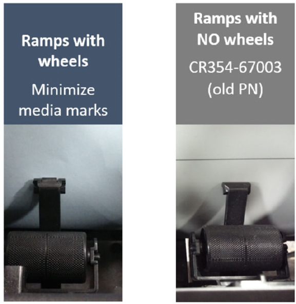
Enable HP-GL/2 palette options
This option was available on legacy T series printers.
It allows the user to be able to congure HP-GL/2 palette options, selecting color/width for the dierent pens.
Content thresholds
This menu allows you to change the default threshold values of HP Designjet Partner Link Pay-Per-Use usage
categories.
●Color value is the maximum % of color pixels in a Mono Lines Category.
●LDI value is the minimum % of non-white pixels with respect to the total pixels on a page to be considered
as the Low Density Image category.
●HDI value is the minimum % of non-white pixels with respect to the total pixels on a page to be considered
as the High Density Image category.
The default values are Color—1%, LDI—10% and HDI—50%. Don’t change these values unless you are sure
about what are you doing.
Please refer to the HP Designjet Partner Link Pay-Per-Use user manual for deeper information about printing
usage categories.
Stacker ramps test
202 Chapter 4 Diagnostics, Service Utilities and Calibrations ENWW

Set I/O factory defaults
This option is the same as the option available in the User Menu (which sets network card default settings: Setup
-> Connectivity -> Network Connectivity -> Advanced -> Restore Factory Settings), however this can reset
additional internal areas of the NVM in case it has been corrupted.
Service Utilities
The following is a list of all internal Service Utilities available in the product. To access them, see Entering the
Service Utilities Menu on page 204.
Turn Drive Roller on page 205
Purge Tubes on page 205
Mark Printhead as Filled on page 206
+ Reset Life Counters on page 206
+ Reset Maintenance Kit usage
Reset life counters PMK1
Reset life counters PMK2
+ Diagnostics Print on page 207
Image Quality Service (Best and Normal)
+ Advanced Diagnostic Print
Paper advance plot
Nozzle Health
Printhead Alignment
Force drop detection
Print reference plot (Normal, Best and Fast)
Set I/O factory defaults on page 203
+ Disk Wipe DoD 5220.22-M on page 212
Insecure mode
1-pass mode
5-pass mode
+Secure File Erase Mode on page 213
Insecure mode
1-pass mode
5-pass mode
Show/Hide Front Panel Information on page 214
File System Check on page 214
+Rewinder Adjust on page 214
Adjust rewinder 1
ENWW Service Utilities 203

Adjust rewinder 2
Disable Upper Roll Cover on page 215
Enable Upper Roll Cover on page 215
+Double Cut for Borderless Printing on page 215
Enable
Disable
Remove non Factory Papers on page 215
Scanner Validation on page 215
Adjustment scanner Y-Axis scale on page 223
Reset Access Control on page 227
Uninstall Applications on page 228
+ Accounting Mode on page 229
None
Mode 1
Test
+Content thresholds on page 202
COLOR
LDI
HDI
+Advance media stop position on page 229
ON
OFF
View startup code on page 229
Entering the Service Utilities Menu
1. From the Home Screen press the Information icon on the top left corner of the screen. For information
regarding the Front Panel keys.
2. From the product Information Area, press the Main Menu tool icon on the bottom right corner of the screen.
3. Scroll down to the lowest menu option and press on the Service menu option.
4. Enter the 4-digit 1st level access code “3174” and press OK.
5. Press on the Service utilities menu option.
6. From the Service utilities menu you can scroll up and down the available utilities. Press on the selected
menu option.
204 Chapter 4 Diagnostics, Service Utilities and Calibrations ENWW

Turn Drive Roller
The purpose of this Service Utility is to rotate the Drive Roller and the Overdrive in order to clean them.
NOTE: Remove the media from the product before proceeding with the procedure.
Perform the Turn Drive Roller utility as follows:
1. Remove Media from the paper path.
2. the Service Utilities submenu, scroll to Turn Drive Roller and press on this menu option.
3. The test begins and the Front Panel displays the following message:
●Rotation started.
4. If paper is loaded, the service utility will be cancelled. In this case, unload the paper and start again from
step 1. If no paper is loaded, the test will continue.
5. The Drive Roller begins to turn slowly and a message is displayed on the Front Panel.
6. To clean the drive roller and overdrive, see the user guide.
7. Once you have nished cleaning the Drive Roller and the Overdrive, press the Cancel key to stop the roller.
Purge Tubes
NOTE: Make sure that NEW Ink Cartridges are installed or that the ink volume remaining in the Ink cartridges is
above 60cc before starting to ll the tubes. If you do not comply, you will get a warning message and the printer
will force you to replace the cartridges.
NOTE: Before using the Purge Tubes utility, you must make sure you have a new printhead.
Perform the Purge Tubes utility as follows:
1. In the Service Utilities submenu, scroll to Purge Tubes and select it.
2. The printer reboots.
3. After a time, a cartridge replacement screen appears.
4. Insert all cartridges and press OK.
5. If any of the cartridges have insucient ink, the cartridge replacement will not allow you to leave until they
have all been purged. You have to replace cartridges that are not valid, and press OK again.
6. When the cartridge replacement process has successfully completed, a printhead replacement will be
opened.
7. The Front panel will prompt you to install a new printhead. Please follow the instructions.
8. The Front Panel prompts you to conrm that the printhead is replaced with a correctly inserted new one. If
it’s correctly inserted, press OK.
9. The product will now perform the Printhead Alignment and Front Panel will prompt you to continue with
the Printhead Alignment, select Align now and press the OK key.
10. Once the Printhead Alignment is completed, the following message will be displayed on the Front Panel.
Press the OK key to continue.
ENWW Service Utilities 205

Mark Printhead as Filled
The printer will ag the printhead as if it has gone successfully through the lling process (See HP 727 Printhead
Start-up process on page 28 for more details). Once agged, the printer will recognize the printhead as lled,
and will try to use it accordingly: print with it, run servicing routines, etc.
Mark printhead as lled in case that the HDD and NVM back ups have been replaced in the printer.
Reset Life Counters
The purpose of this Service Utility is to reset the internal life counters.
There are two submenus that allow you to:
●Reset all the counters related to a Preventive Maintenance Kit (PMK).
●Reset only the counters related to a specic replaced part.
NOTE: ALWAYS RESET THE LIFE COUNTER OF A CORRESPONDING PART AFTER REPLACING IT.
Perform the Reset Life Counters utility as follows:
1. In the Service Utilities submenu, scroll to Reset Life Counters and press this menu option.
2. Enter the 4-digit 2nd level access code “5494” and press OK.
3. Select Reset Maintenance Kit usage to reset the Life Counter for all parts included in a Preventative
Maintenance Kit (PMK).
You can choose from the following Preventive Maintenance Kits:
●Preventive Maintenance Kit 1 (PMK1).
●Preventive Maintenance Kit 2 (PMK2).
NOTE: For more information about the counters that are reset, See the user guide.
It is also advisable to check the status of the Life Counters related to the other Preventive Maintenance Kits
to avoid multiple trips to the customer.
4. Select Reset usage counters to reset the Life Counter of a single part.
●Tubes and Trailing Cable
●Scan-Axis Belt with Tensioner
●Scan Motor
●Full Bleed Foams
●Carriage
●Service Station
●Scanner Counters
If you replace a part, you should reset the Life Counters as follows:
206 Chapter 4 Diagnostics, Service Utilities and Calibrations ENWW

Replaced part Reset Life Counters
Ink supply tubes (with trailing cables) Tubes and Trailing Cable
Belt assembly Scan-Axis Belt with Tensioner
Scan-axis motor Scan-Axis Motor
Foams Full Bleed Foams
Carriage assembly Carriage
Service station Service Station
Drop detector Drop Detector Working Time
5. Once you have selected the Life Counters to reset, a message similar to the following will be displayed on
the Front Panel. Press the OK key to reset the selected Life Counters or press Cancel to exit without
resetting the Life Counters.
Diagnostics Print
This is a set of diagnostic prints used to highlight printhead reliability, or other printer problems that can aect
the Image Quality of the printer.
To print any of the Image diagnostics prints:
1. Use the same paper type that you were using when you detected the problem.
2. Check that the selected paper type is the same as the paper type loaded into the printer.
ENWW Service Utilities 207
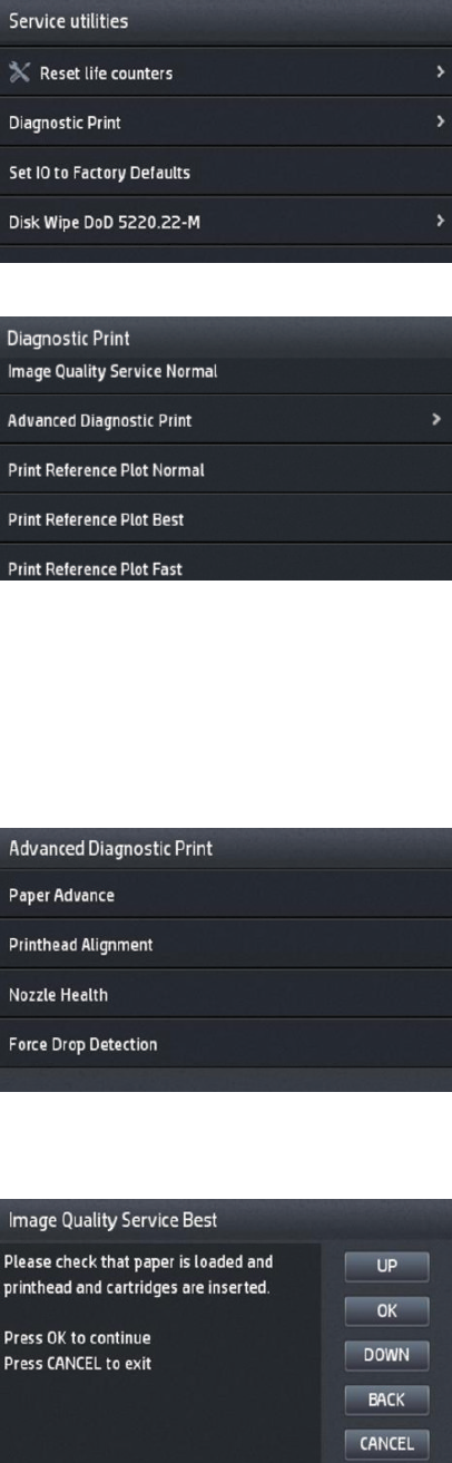
3. In the printer's front panel, select Diagnostic image.
In Diagnostic Print, you can select the Image Quality Service prints or the Diagnostic Print:
You have the option to print the Image Quality Service in Normal or Best mode.
Image Quality Service plots allow checking the print quality that the printer can deliver for every color of the
printer separately: Cyan/Magenta/Yellow/Matte Black/Black/Gray.
Besides the Image Quality Service plots, also available is the Print Reference Plot in Fast/Normal/Best. This
plots allows checking print quality using jobs that contain user images that have been already ripped.
Advance Diagnostic Print has the following Diagnostics available:
All the diagnostic Prints (except Force Drop Detection) require that the printer be ready to print (paper
loaded, printhead and supplies installed). At the beginning of each diagnostic, you will see the following
screen:
208 Chapter 4 Diagnostics, Service Utilities and Calibrations ENWW

Image Quality Service (Best and Normal)
This diagnostic helps you to check the performance of the printhead, and whether it suers from clogging, lack
of ink in any color, or other problems.
This diagnostic is quite similar to the Diagnostic Print available in the user level, except that the image quality
level (best, normal) can be chosen.
Use a level of Image Quality similar to the settings of the prints with Image Quality problems.
Use the “normal” level to troubleshoot problems in normal and fast mode, and the “best” one for prints in best
mode.
The print is divided into three parts:
●Part 1 (top): consists of rectangles of pure colors at 100% and 50%; one for each ink. This part represents
the print quality that you will get from each color in the selected level of quality (best or normal).
●Part 2 (mid) : consists of small dashes; one for each printhead nozzle. This part complements the rst, and
aims more specically to detect how many faulty nozzles each printhead has.
Please look carefully at the print. The names of the colors are shown above the rectangles and to the left of the
patterns of dashes.
Before printing this image, perform a Force Drop Detection action (available on the Advance Diagnostic Print
Menu), in order to update the status of faulty nozzles, and print the printhead nozzle health more accurately.
First look at the upper part of the print (part 1). Each colored rectangle should be a uniform color without any
horizontal lines.
Then look at the bottom part of the print (part 2). For each individual colored pattern, check that most of the
dashes are present.
If you see horizontal lines in part 1, and also missing dashes in part 2 (same color), you should clean the
printhead, selecting the relevant color group. If the rectangles look solid, do not worry about just a few missing
dashes in part 2; these are acceptable as the printer can compensate for a few clogged nozzles.
●Part 3 (bottom): consists on several bars from side to side of the print, one for each ink. The aim of this part
is to detect a high number of consecutive faulty nozzles during continuous printing (for example caused by
air ingestion or lack of ink in the printhead).
ENWW Service Utilities 209

In the case of detecting a high number of consecutive faulty nozzles in any of the color bars, you should clean
the printhead, selecting the relevant color group.
If the problem persists after recovering the printhead, consider replacing it.
Paper advance plot
The Visual Paper Advance Diagnostic prints a test plot to check that the paper advance is operating correctly.
It consists of three plots printed at the left, center, and right of the paper. These three plots are the same, and
contain several numbered columns. The following illustrations shows an example of the Visual Paper Advance
Diagnostic plot:
The most uniformly centered will be the white/lightest band; better the media advance the printer has.
This should be true for all three plots or the printer will have dierential banding (a dierence of advance
between the left and right).
When the white / light band is clearly not uniform (in the same band or comparing to the other bands), perform a
user paper advance calibration, in the Image Quality maintenance menu (see User Guide for more details).
Nozzle Health
Nozzle health print is an extended version of the Image Quality Service prints, focused exclusively on nozzle
health. It’s not intended to help to understand overall banding problems, used only for specic nozzle health
problems.
For each individual colored pattern, check that most of the dashes are present. If you see missing dashes in one
color, you should clean the printhead, selecting the relevant color group.
Printhead Alignment
The printhead alignment diagnostic print shows several groups of vertical lines, each one printed in one color
and with dierent carriage speeds (30, 40 and 60 inches per second).
210 Chapter 4 Diagnostics, Service Utilities and Calibrations ENWW
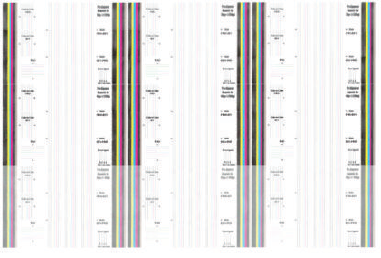
The aim of the diagnostic is to detect printhead alignment problems by looking at how straight the three groups
of thin vertical lines that go from top to the bottom are.
If the diagnostic shows severe straightness / continuity problems in any of these lines, perform a printhead
alignment.
Force drop detection
If the Nozzle Print Test plot has persistent white-point banding in only one color that cannot be xed with a
printhead recovery, you can use this option to resolve the problem by resetting the nozzle health database so
that all nozzles are assumed to be correct. Once the nozzle health database has been reset, drop detection is
forced.
The normal cause of this white-point banding in a single color is the incorrect detection of failed nozzles by the
drop detector.
Perform the test as follows:
1. Go to the Service utilities menu and select Diagnostic Print.
2. Select Advanced Diagnostic Print.
3. Select Force Drop Detection.
4. Make sure that the ink system is ready, and the covers and doors are closed, then press OK.
5. The printer performs drop detection.
6. When the process has ended, press OK to return to the menu.
Print Reference Plot
The reference plot is a sRGB HPGL2 image that can help to check some Print Quality attributes:
●Banding
●Grain
●Ink quantity
●Line quality
The image is printed to the stacker on the media type currently loaded and in "ready" state.
ENWW Service Utilities 211
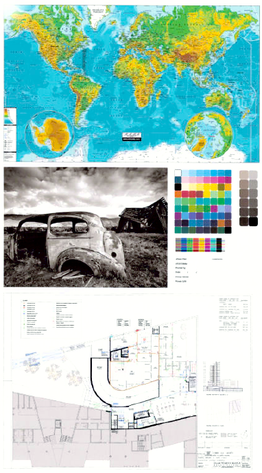
Set I/0 to factory defaults
Disk Wipe DoD 5220.22-M
The purpose of this Service Utility is to erase data from the Hard Disk securely, according to the directive DoD
5220.22-M.
The product's hard disk is used as a temporary storage area for print jobs. The Secure Disk Wipe utility can erase
user information from the hard disk to prevent unauthorized access.
Secure Disk Wipe provides three dierent levels of security:
●Unsecure Mode: All pointers to the information are erased. The information itself is not erased, and
remains on the hard disk until the disk space it occupies is needed for new print jobs. The new print
information overwrites the old information. While the information remains on the disk, it is dicult for most
people to access, but may be accessed using software designed for that purpose. This is the normal
212 Chapter 4 Diagnostics, Service Utilities and Calibrations ENWW

method in which les are erased on most computer systems; it is the fastest method but the least secure.
This is the default security level when using Secure Disk Erase.
●1 Pass Mode: All pointers to the information are erased, and the information itself is impapertely
overwritten with a xed character pattern. This method is slower than Non-Secure Fast Erase, but more
secure. It may still be possible to access fragments of the erased information by using special tools to
detect residual magnetic traces.
●5 Pass Mode: All pointers to the information are erased, and the information itself is repetitively
overwritten using an algorithm designed to eliminate any residual traces. This is the slowest method, but
the most secure. Secure Sanitizing Erase meets the US Department of Defense 5220-220M requirements
for clearing and sanitization of disk paper.
Execute the Disk Wipe DoD 5220.22-M utility as follows:
1. In the Service Utilities submenu, scroll to Disk Wipe DoD 5220.22-M and press this menu option.
2. In the Disk Wipe DoD 5220.22-M submenu, scroll to Sanity Level and press OK.
3. In the Sanity Level submenu, scroll to the required Sanity Level and press OK.
NOTE: Erasing the Hard Disk drive using either of the Secure Sanitize Levels is a very slow process, 6
hours for the 1 Pass mode and 40 hours for the 5 Pass mode.
4. When the Sanity Level has been changed, the Front Panel displays a message, or an error message if there
is some problem.
5. In the Disk Wipe DoD 5220.22-M submenu, scroll to Disk Wipe (DoD 5220.22-M) and press OK.
6. A message appears on the Front Panel, you must select whether you would like to perform a complete
erase of the Hard Disk Drive using the previously selected erase mode by pressing OK. Press Cancel to exit
the utility.
7. A message appears on the Front Panel, you must select whether you want to continue and completely
erase the Hard Disk Drive by pressing OK. Press Cancel to exit the utility.
8. The erase process starts and the Front Panel shows a setup progress bar.
9. The product reboots into the Disk Wipe mode, and continues with the disk erase until it is completed.
CAUTION: Do not try to interrupt this process. All Front Panel keys are disabled while the product erases the
Hard Disk Drive.
Secure File Erase Mode
The purpose of this Service Utility is to erase data from the printer's Hard Disk.
The product's hard disk is used as a temporary storage area for print jobs. The Secure File Erase Mode utility can
erase information from the hard disk to prevent unauthorized access.
It provides three dierent levels of security:
ENWW Service Utilities 213

●Insecure Mode: In this mode, all le pointers to the data (table indexes) are erased. The contents of the le
remain on the hard disk until the disk space they occupy is needed for other purposes, the space is then
overwritten. This is the fastest mode of operation.
●1-Pass Mode: In this mode, le pointers are erased and the disk space where the contents of the le were
stored is overwritten with a xed character pattern. This mode of is slower than Non-Secure Fast Erase, but
all data is overwritten.
●5-Pass Mode: In this mode, le pointers are erased and the disk space where the contents of the le were
stored is overwritten 5 times using an algorithm that prevents any residual data. This mode may aect
product performance.
Execute the Secure File Erase utility as follows:
1. In the Service Utilities submenu, scroll to Secure File Erase Mode and press this menu option.
2. In the Secure File Erase Mode submenu, choose the mode you want to execute (Insecure Mode, 1-Pass
Mode or 5-Pass Mode).
3. Wait for the diagnostic result and press OK.
NOTE: Erasing the les of the Hard Disk drive using either of the 1-Pass Mode or 5-Pass Mode is a very slow
process; 6 hours for the 1-Pass mode and 40 hours for the 5-Pass mode.
Show/Hide Front Panel Information
The purpose of this utility is to prevent network information from being viewed directly from the EWS or the
screen of the Front Panel.
1. In the Service Utilities submenu, scroll to and select Show/Hide Front Panel Info.
2. Use the Up and Down button to change if network information is viewable, press OK to conrm.
3. The change is complete, press OK to return to the main menu.
File System Check
The File System Check checks the le system on the hard disk and automatically corrects any problems that it
nds.
1. In the Diagnostics menu, select File System Check and press on this menu option.
2. The Front Panel asks you if you want to proceed with the File System Check.
3. Press OK to proceed or Back/Cancel to exit.
If you press OK, the product restarts and the File System Check is performed.
Rewinder Adjust
The Rewinder Adjust utility clears the calibration parameters associated with a Rewinder motor when it has to be
replaced.
The changes made by this utility take eect only after the product has been restarted. Therefore, you are
recommended to proceed in the following order.
1. Use the Rewinder Adjust utility to reset the calibration parameters.
214 Chapter 4 Diagnostics, Service Utilities and Calibrations ENWW
a. In the Service Utilities submenu, scroll to Rewinder Adjust and press on this menu option.
b. Enter the 4-digit 2nd level access code “5494” and press OK.
c. Select the Rewinder for roll 1 or roll 2 and press OK.
d. Conrm your selection by pressing OK.
e. The product resets the calibration parameters and checks that the default values have been correctly
saved inside the NVM memory. If the check fails, a 79:04 error is generated, and the procedure is
interrupted. Otherwise, the product conrms success.
2. Turn o the product.
3. Replace the Rewinder motor.
Disable Upper Roll Cover
Disables the functionality that makes the printer unload the roll every time the roll cover is opened.
Enable Upper Roll Cover
This utility re-enables the upper roll cover without restarting the product.
1. In the Service Utilities submenu, scroll to, and select Enable upper roll cover.
2. Close the roll cover when requested by the Front Panel.
3. Wait until you see the a message.
4. Press OK.
Double Cut for Borderless Printing
This utility disables the double cut that the printer makes in order to print borderless images on photo media.
Remove non Factory Papers
This utility removes the paper proles that were installed by the user. It does not remove any original paper
prole shipped with the printer.
Use this utility when a paper prole installed by the user could be the cause of the problem.
1. In the Service Utilities submenu, scroll and select Remove non factory papers.
2. Press OK to conrm the removal.
Scanner Validation
By executing this validation, the product will perform the following scanner tests:
●ScanDump
●Focus
●Skew
●Dead/hot pixels
ENWW Service Utilities 215
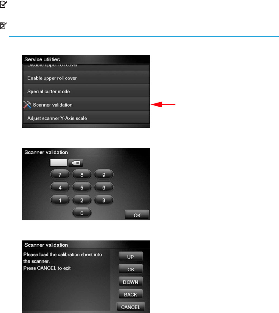
●Alignment/Stitching
●Chromatic aberration
●Streak
●Gray matching
●Signal noise
NOTE: Before running the scanner validation check that the calibration sheet is free from dust, spots or stripes.
Check that the calibration sheet is not dirty, wrinkled, scratched or folded.
NOTE: Before running the scanner validation open the scanner to check that the glass plate is free of dirt, dust
and scratches. Clean the glass plate if necessary before proceeding.
1. In the Service Utilities submenu, scroll down and select the Scanner validation option.
2. Enter the 4-digit 2nd level access code “5494” and press OK.
3. The Touch Control Panel will then prompt you to load the calibration sheet.
216 Chapter 4 Diagnostics, Service Utilities and Calibrations ENWW
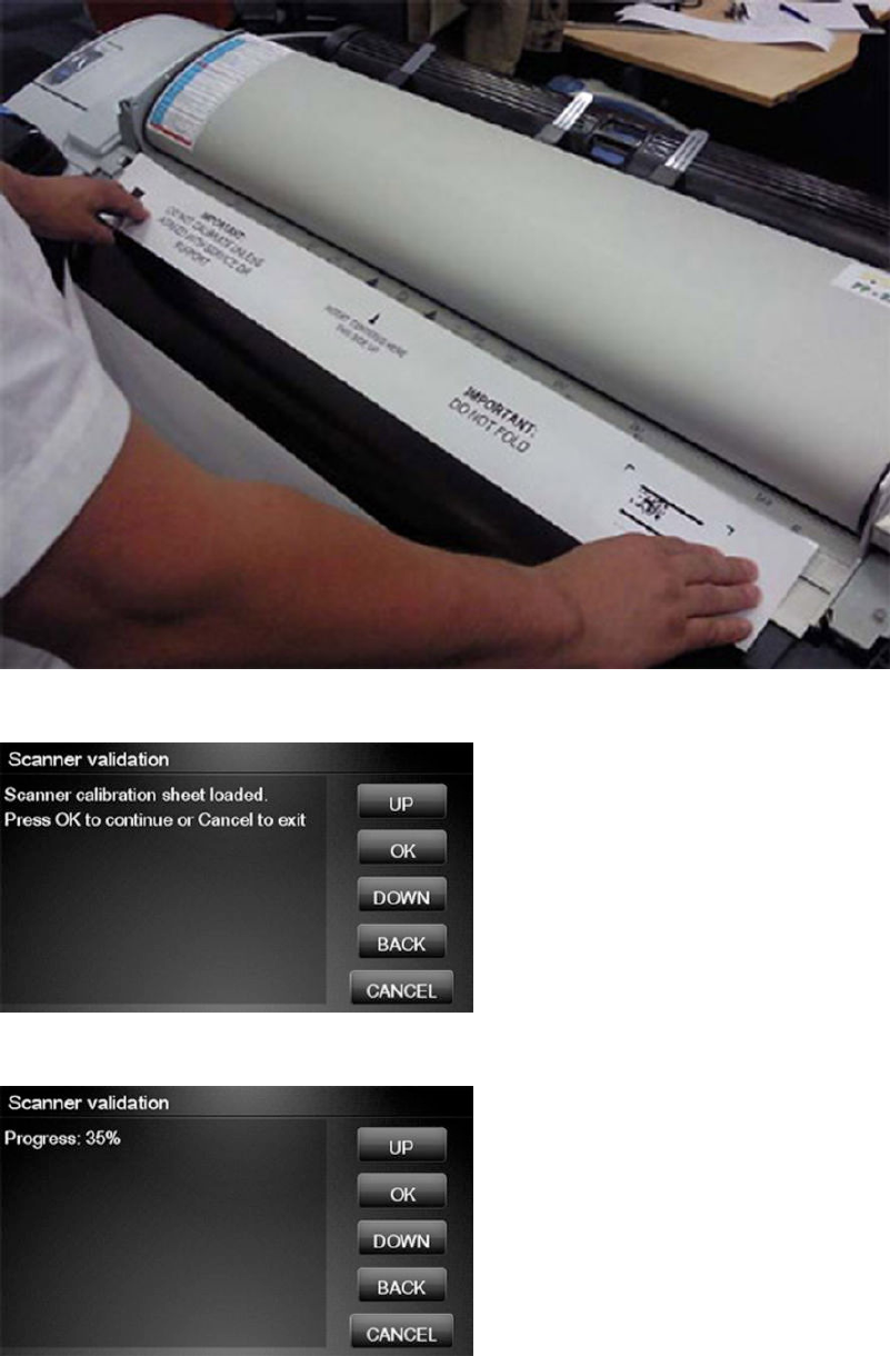
4. Hold the calibration sheet from both sides and place it facing the arrow in the centre of the sheet in front of
the Page icon present on the input tray of the scanner. Push the sheet with both hands on both sides at the
same time to load the sheet with no skew. Press OK to continue with the test.
5. Press OK to continue with the test.
6. The Touch Control Panel will then display a percentage with the progress of the validation.
ENWW Service Utilities 217
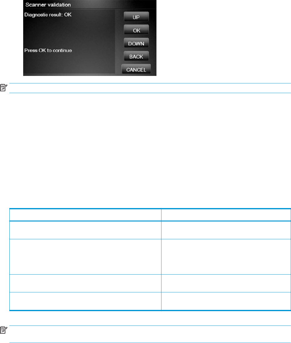
7. Wait until the scanner validation test has completed. The Touch Control Panel will then show the test
results. Press OK to continue
NOTE: If scanner validation result is FAIL then:
●Check that the calibration sheet is in good condition according to previous note. Replace with a new one if
necessary.
●Check that the 5 glass plates are in good condition. Replace with new ones if necessary.
●Inspect that the 5 glass plates are correctly installed, and that they are clean.
●Perform a scanner calibration and repeat the validation.
●If the scanner validation result is FAIL with error CWS_RC_VAL_DEADPIXEL_FOUND, replace the individual
CIS module accordingly.
After the validation, a set of les is saved in the CWS_validation folder. SCANdump and log les will be written
every time a validation is being executed. TIFF les will only be written if a test fails. If the validation is performed
again the les are overwritten. The following les are written:
File name CWS_validation folder
SCANdump_Xxx.con SCANdump les can be opned with SCANview. (part of
SCANtest)
scanTRUSTresult.log Results le, contains the following:
●Measured values and limits
●Error codes (if any)
scanTRUST.log The Log le. Primarily contains information that can help
troubleshoot where an error has occurred.
*.tif Scanned images of failed tests. These are mainly for
escalation to division for troubleshooting purposes.
NOTE: The Diagnostic package (reduced level) will contain only all LOG and CON les. Extended diagnostic
package (full level) will contain all les.
SCANdump
SCANdump is an archive le that can be viewed with SCANview (SCANtest). The SCANdump le consists of the
following:
218 Chapter 4 Diagnostics, Service Utilities and Calibrations ENWW
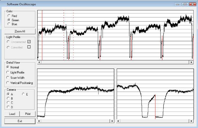
●Four light proles (see below for an explanation on Light Proles).
–RGB: Unadjusted.
–RGB: Adjusted.
–Grey: Unadjusted.
–Grey: Adjusted.
●A statistic le and documentation about how to use the system.
Light Proles
The light proles are a snapshot of what the image sensor sees at the time the SCANdump was made. The light
proles will in some degree be aected by of wear and tear, cleanness, and also the condition of the calibration
sheet that was used to calibrate the unit. There are two types of light prole, adjusted and unadjusted.
The Unadjusted light prole is a raw picture of the light source. All imperfections of the sensors and the light
guide (in one, the CIS elements), are visible. Only the general light level has been manipulated.
The Adjusted light prole is corrected according to the calibration sheet, in other words, the calibration sheet has
been used as a reference to correct the imperfection of the CIS elements.
ENWW Service Utilities 219
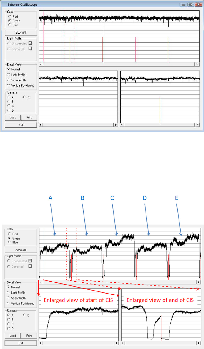
Since we do the basic calibration in two modes, one for the color channels and one for Gray, two sets of proles
are included in the SCANdump le.
General view of the light prole
This is the overview screen of the proles of the CIS elements, here shown as A, B; C; D; E. Each arc represents a
CIS element. The lower half of the screen can be used to amplify the prole of a selected CIS element, for a
closer look.
Reading the Uncorrected Light Prole
A uncorrected light prole should be within the Min/Max shown here. Since the Light source is located at the end
of the CIS element it is normal that the light prole’s level is higher here and that the level drops a little towards
the center of the CIS.
220 Chapter 4 Diagnostics, Service Utilities and Calibrations ENWW
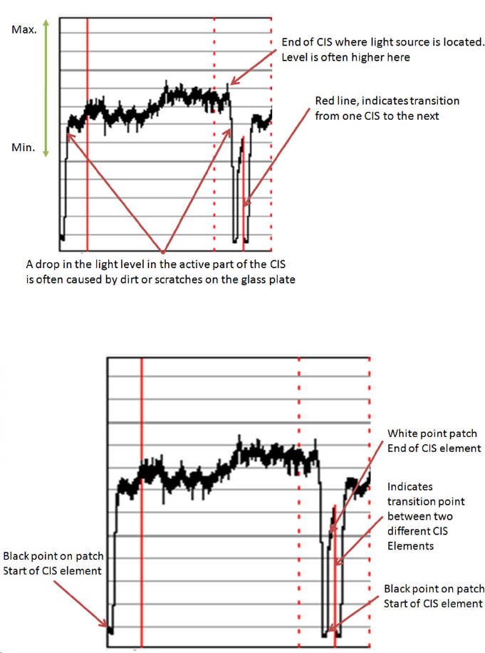
A white patch is located at each end of the CIS element. The one at the start of the CIS is a bit smaller than the
one at the end, it makes a black point, unlike the end which makes a Black and a White point.
Reading the Corrected Light Prole
A corrected light prole should be within the Min/Max shown here.
ENWW Service Utilities 221
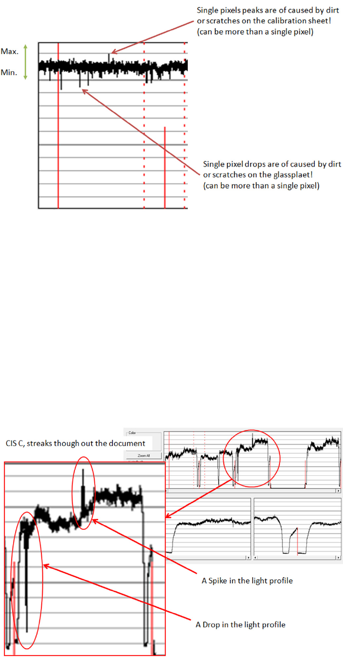
Peaks will show up in a scan as a lighter color and not necessarily in all colors, it depends on which color
channels are being aected by the dirt/ scratch.
Drops will be seen as a dark line in the scan and again not necessarily in all colors, it depends on which color
channels are being aected by the dirt/ scratch.
If the peak or the drop is within 1-2 div (lines) it is usually not noticeable in the scan and is just general noise. The
dirt or the scratch can be from one pixel to several!
Statistics File
This le contains useful information about the usage of the system, along with rmware version and last
calibration date.
Troubleshooting image quality using the light proles
A drop in the light prole is often caused by dirt/dust on the glass plate A spike is related to the calibration, either
dirt or dust on the glass plate during the calibration or a dirty calibration sheet.
222 Chapter 4 Diagnostics, Service Utilities and Calibrations ENWW
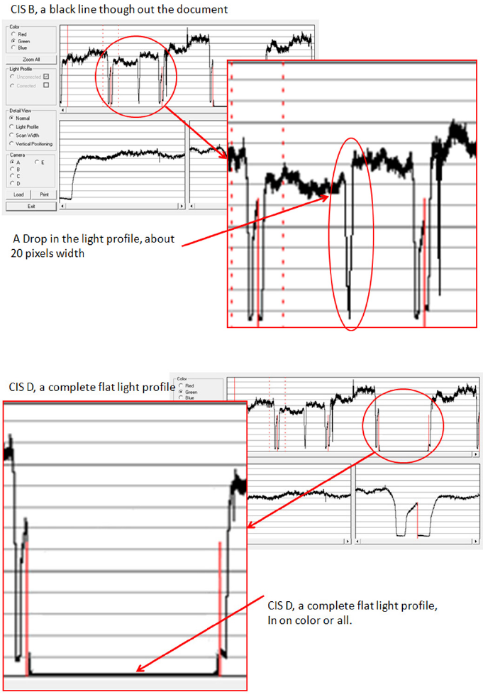
A light prole with an about 20 pixel drop can be a contaminated lens in the CIS module.
A light prole with an about 20 pixel drop can be a contaminated lens in the CIS module.
A completely at light prole in one color or all colors can either be one specic LED or the entire CIS module that
is faulty.
Adjustment scanner Y-Axis scale
The scanner may produce a vertical distortion in scanned images. It is important in CAD plots to maintain the
aspect ratio of the originals. The purpose of this utility is to correct this vertical distortion. This sections describes
how to calculate and set the Y-Axis adjustment scale.
ENWW Service Utilities 223
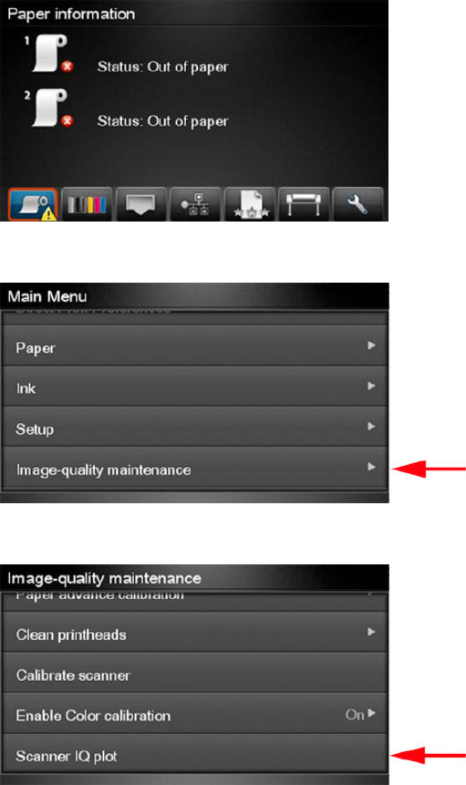
Use the following procedure to print the Scanner IQ plot.
1. From the Home Screen press the Information icon on the top left corner of the screen. For information
regarding the Touch Control Panel keys.
2. From the product Information Area, press the Main Menu/tool icon on the bottom right corner of the
screen.
3. From the Main Menu, scroll down and select the Image-quality maintenance option.
4. From the Image-quality maintenance menu, scroll down and select the Scanner IQ plot to print.
5. The next procedure describes how to copy the Scanner IQ plot:
224 Chapter 4 Diagnostics, Service Utilities and Calibrations ENWW
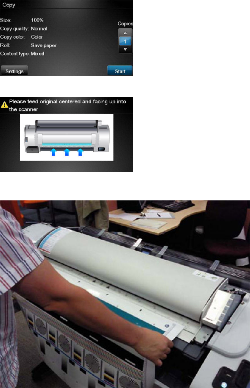
6. From the Home Screen press the Copy icon on the left side of the screen
7. Press Start.
8. The Control Panel prompts you to feed the original. Load the Scanner IQ plot that you printed previously in
the Scanner input tray. Wait then for the product to scan and print the image.
ENWW Service Utilities 225
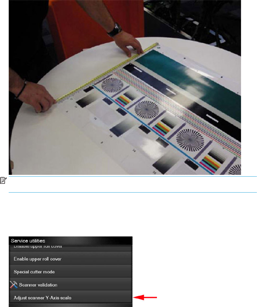
9. Follow the next steps to calculate the Y-Axis adjustment scale: Measure the total length of the two vertical
rules at both sides of the copied plot (we call it M1 and M2).
NOTE: If M1 is quite dierent from M2 (more than 1mm or 1/16th inch) then refer to incorrect paper
advance, skew during scanning, or horizontal wrinkles in the Image-quality troubleshooting.
10. If M1 and M2 are similar (within 1mm or 1/16th inch) then consider M1 = M2 = M and calculate P as: Y-Axis
adjustment scale = -100 × ( M – T ) / T Where T is the total length of the vertical rules (T = 22 inches or 570
mm). Follow the next steps to set the Y-Axis adjustment scale:
11. In the Service Utilities submenu, scroll to the Adjustment scanner Y-Axis scale and press on this option.
226 Chapter 4 Diagnostics, Service Utilities and Calibrations ENWW
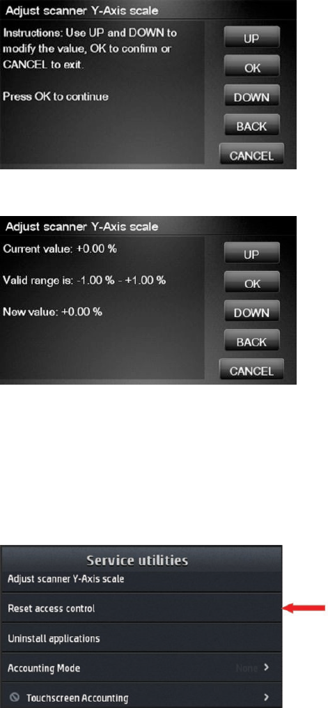
12. Press OK to continue.
13. Press UP and DOWN to pre-set the new value of Y-Axis adjustment scale and press OK.
14. Repeat the process from step 6 onwards until M is equal to T.
Reset Access Control
The purpose of this Service Utility is to reset the Embedded Web Server access control to default; both the admin
username and password, and other users passwords are set to “ ”.
1. In the Service Utilities submenu, scroll to Reset access control and select it.
ENWW Service Utilities 227
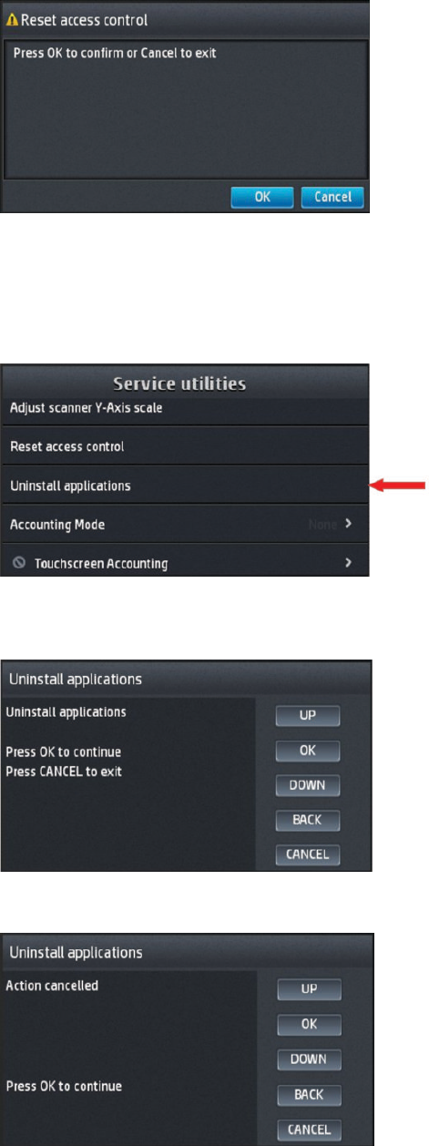
2. Press OK to conrm and continue with the reset or Cancel to exit.
Uninstall Applications
With this Utility all the applications that currently are installed in the printer will be removed.
1. In the Service Utilities submenu, scroll to Uninstall applications and select it.
2. A message similar to the following will be displayed in the Front Panel. Press the OK button to remove the
installed applications, or press Back or Cancel to exit.
3. If Cancel was selected, the screen below is displayed; press OK to exit to the Service Menu.
228 Chapter 4 Diagnostics, Service Utilities and Calibrations ENWW
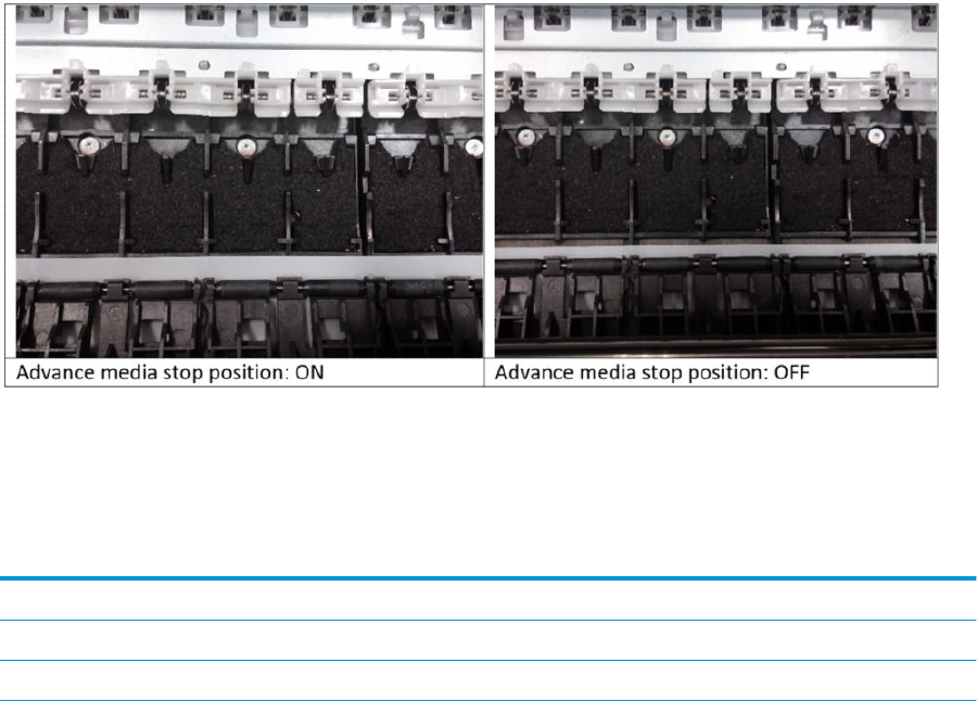
Accounting Mode
Used to enable the Abacus accounting tool (available in the US only).
Content thresholds
This menu allows you to change the default threshold values of HP Designjet Partner Link Pay-Per-Use usage
categories.
●The Color value is the maximum % of color pixels in a Mono Lines Category.
●The LDI values are the minimum % of non-white pixels with respect the total pixels in a page to be
considered to be in the Low Density Image category.
●The HDI values are the minimum % of non-white pixels with respect the total pixels in a page to be
considered to be in the High Density Image category.
The default values are Color:1%, LDI:10% and HDI:50%. Don’t change these values unless you are sure about
what are you are doing.
Please refer to the HP Designjet Partner Link Pay-Per-Use user manual for deeper information about printing
usage categories.
Advance media stop position
This utility allows to make the paper stop further from the pinch rollers. This helps to prevent the leading edge of
the page to crash against the rips of the platen generating marks on the top of the print.
View startup code
This option provides a hexanumeric code that allows you to verify the status of printhead installation according
the following table:
Table 4-1 PHA status decoding table
Ox
0000 Current PHA status
0000 PHA status after servicing
ENWW Service Utilities 229

Table 4-1 PHA status decoding table (continued)
0000
First temperature check deltas
Pk
00 G
00 Mk
00 C
00 M
00 Y
00 First optotrip check results
00 Second optotrip check results
00 Third optotrip check results
00 Fourth optotrip check results
00 Fifth optotrip check results
00 Sixth optotrip check results
00 Seventh optotrip check results
00 Eighth optotrip check results
00 Ninth optotrip check results
00 Tenth optotrip check results
00 Eleventh optotrip check results
00 Twelfth optotrip check results
PH status (current, EE and after servicing)
See Printhead 727 Error codes on page 82.
Temperature check result
There are a total of four distinct cases for Printhead temperature:
0x00 0x01–0xFD 0xFE 0xFF
The delta* is less than or equal
to 0 degrees
You must convert the value to
decimals and divide by 5 to
obtain the delta* temperature
The delta* is higher than 50
degrees
The Printhead detected that the
temperature is too high
*Delta: the dierence between the temperature before and after spitting. A high delta indicates that there might
not be enough ink in the Printhead.
Optotrip check
Every bit of an optotrip check represents a color slot:
230 Chapter 4 Diagnostics, Service Utilities and Calibrations ENWW

b 0 0 0 0 0 0 0 0
- - Pk G Mk C M Y
The bit is set to 0 if the NOA of that color does not open or to 1 otherwise. If the test is not run the bits are not
agged and remain 0.
Es: 3F all colors open, 00 no colors open (or test not run).
ENWW Service Utilities 231

Service Calibrations
The product has several calibration procedures that must be performed under certain conditions.
NOTE: REMEMBER THAT CERTAIN CALIBRATIONS ARE REQUIRED EVEN IF AN ASSEMBLY HAS BEEN
DISASSEMBLED TO GAIN ACCESS TO ANOTHER ASSEMBLY OR COMPONENT.
The following is a list of all internal service calibrations available in the product. For instructions to enter the
service calibrations menu, see Entering the Service Calibrations Menu on page 232.
+ Paper Advance Calibration on page 232
Print
Scan
+ Drop Detector Calibration on page 235
Calibrate drop detector
Reset calibration ag
Line Sensor Calibration on page 236
Stacker overdrive calibration on page 238
NOTE: If all the Calibrations need to be performed (for example, when both the Formatter and the Engine PCA
have been replaced), you must perform them in the above order.
Entering the Service Calibrations Menu
1. From the Home Screen press the Information icon on the top left corner of the screen. For information
regarding the Front Panel keys, see The front panel on page 35.
2. From the product Information Area, press the Main Menu tool icon on the bottom right corner of the screen.
3. Scroll down to the lowest menu option and press on the Service menu option.
4. Enter the 4-digit 1st level access code “3174” and press OK.
5. Press on the Service calibrations menu option.
6. From the Service calibrations menu you can scroll up and down the available utilities. Press on the selected
menu option.
NOTE: In some cases a quick press of a button may not be recognized by the product. When pressing a button,
be sure to press it rmly.
Paper Advance Calibration
The purpose of this Service Calibration is to calibrate the nominal advance of the paper. This calibration is
necessary to control the exact movement of the paper in order to avoid print quality problems like banding.
If you need to perform a Paper Advance Calibration to solve a print quality problem, it is recommended that you
rst try the Paper Advance Calibration from the user's menu, which will calibrate the product to a specic paper
type.
232 Chapter 4 Diagnostics, Service Utilities and Calibrations ENWW

NOTE: You can perform Paper Advance Calibration on a sheet or roll, but the paper type should always be HP
Universal Instant-dry Photo Gloss. You are recommended to order the Paper Advance Calibration Kit (36 in
model: CR357-67079), which contains two sheets of HP Universal Instant-dry Photo Gloss paper. You can also
perform this calibration by using cutsheets created from a roll, with a minimum width of 23 inches and a
minimum length of 18 inches.
Perform the Service Accuracy Calibration whenever:
●Banding is detected in prints.
Service calibrations also need to be performed after removing or replacing certain product components. If you
have removed or replaced product components, check the user guide to see which tests and calibrations you
need to perform.
The Paper Advance Calibration is split into two parts and should always be done in this order:
1. Print Calibration Pattern - The product rst calibrates the Analog Encoder and then prints the Paper
Advance Calibration pattern.
2. Scan Calibration Pattern - The product scans the Paper Advance Calibration pattern in order to calibrate the
nominal advance of the paper.
NOTE: Only scan the Calibration Pattern in the product that was used to actually print it. Using the
Calibration in a dierent product could cause it to experience paper advance problems. After scanning the
Calibration Pattern, it should be discarded.
Perform the Paper Advance Calibration as follows.
1. Unload paper from the product.
2. In the Service Calibrations submenu, scroll to Paper advance calibration and press OK.
3. In the Paper Advance Calibration submenu, scroll to Print Calibration Pattern and press OK.
4. When the following message appears on the Front Panel, you must select whether you would like to
continue with the calibration by pressing the OK key. Press Cancel to exit the calibration.
5. If paper is detected, the product will prompt you to remove it. If paper is not detected, the calibration will
continue.
6. The product will start to calibrate the Analog Encoder and the following message will be displayed on the
Front Panel.
If the Calibration is not done or if the values are out of the limits, a warning message will appear on the
Front Panel. In this case, try the following:
●Check that the product has the latest rmware version. If not, update the rmware to the latest
version.
●Retry the Paper Advance Calibration.
7. Once the Analog Encoder has been calibrated correctly, the Front Panel prompts you to select the type of
paper you will use. Use the Arrow keys to choose roll or sheet paper. Press the OK key to start loading the
paper.
8. The Front Panel prompts you to load the paper. Make sure you load the paper that corresponds to your
paper type selection.
ENWW Service Calibrations 233

9. The Front Panel prompts you to select the paper category you will use for the calibration. Scroll to your
paper category and select it to continue the paper load process.
10. The Front Panel prompts you to select the specic type of paper you will use for the calibration. Scroll
through the menu and select your paper type.
11. The Front Panel displays the following screen, press ok.
12. Once the paper is loaded into the product, a message will appear on the Front Panel.
13. Press OK to continue.
14. The product advances and reels in about a meter of paper. The Front Panel displays the following
messages:
●Advancing Paper
●Printing Pattern
15. The product will start to print the Paper Advance Calibration Pattern. This could take several minutes during
which a message will be displayed on the Front Panel.
16. When the Calibration Pattern has been printed successfully, the Front Panel reminds you to leave it to dry
for a while.
17. When the Calibration Pattern is dry, the Front Panel will prompt you to continue. Press OK.
18. Return to the Paper Advance Calibration submenu, scroll to Scan Calibration Pattern and press OK
19. When the following message appears on the Front Panel, you must select whether you would like to
continue with the calibration by pressing the OK key. Press Back or Cancel to exit the calibration.
20. A message will appear advising you that you will need to load the Calibration Pattern into the product. Make
sure that you rotate the printed pattern 90° clockwise and reload it printed-side down, so that the black
arrows go into the product rst. Press the OK key to continue.
NOTE: Only scan the Calibration Pattern in the product that was used to actually print it. Using the
Calibration in a dierent product could cause it to experience paper advance problems.
After scanning the Calibration Pattern, it should be discarded. When loading the Calibration Pattern, use the
Cutter blade on the Print Platen to align the edge of the sheet. If you follow this advice, you will prevent the
cutter from cutting a section of the Calibration Pattern, which could cause the Calibration to FAIL.
21. The Front Panel prompts you to select the paper category you used for the calibration. Select the same
paper that you used to perform the Paper Advance Calibration print. Use the Arrow keys to scroll to your
paper category and press the OK key to continue the paper load process.
22. The Front Panel prompts you to select the specic type of paper you used for the calibration. Use the Arrow
keys to scroll through the menu and the OK key to select your paper type.
23. Load the calibration pattern into the product and the Front Panel displays the normal sheet loading
procedure.
234 Chapter 4 Diagnostics, Service Utilities and Calibrations ENWW

24. When the Calibration Pattern is successfully loaded the Front Panel displays the following screen, press OK
to start the scan.
25. The Front Panel displays the following screen. The product will scan the Calibration Pattern which could
take several minutes. Once the calibration is completed successfully, a message will be displayed on the
Front Panel. Press the OK key to continue.
If the Paper Advance Calibration fails for any reason, a warning message will appear on the Front Panel. In
this case, try the following:
●Check that the Calibration Pattern was not incorrectly cut (trimming the actual pattern) during the
paper load process. If this is the case, perform the Paper Advance Calibration again from step 1.
●Perform a Line Sensor Calibration. See Line Sensor Calibration on page 236.
●Replace the Line Sensor. See the user guide.
●If the problem continues, replace the Media Advance Driver. See the user guide.
Drop Detector Calibration
The purpose of this Service Calibration is to calibrate the Drop Detector (located in the Service Station) in relation
to the Carriage Assembly. There are two menu options to calibrate the Drop Detector:
●Calibrate Drop Detector
●Reset Calibration Flag
Always perform the Reset Calibration Flag calibration BEFORE calibrating the drop detector.
Service calibrations also need to be performed after removing or replacing certain product components. If you
have removed or replaced product components, check the user guide to see which tests and calibrations you
need to perform.
Reset Calibration Flag
Run this option before replacing the drop detector (service station), so that the product will not try to perform a
drop detection until the new drop detector has been calibrated.
1. In the Service Calibrations submenu, select Drop Detector calibration and press OK.
2. In the Drop Detector Calibration menu, scroll to Reset Calibration Flag and press OK.
3. When the following message appears on the Front Panel, you must select whether you would like to
continue with the calibration by pressing the OK key. Press Cancel to exit the calibration.
4. The product resets the calibration ag. Press OK to return to the menu.
5. Shut down the product and replace the drop detector.
6. Start the product and calibrate the drop detector.
Calibrate Drop Detector
1. In the Service Calibrations submenu, scroll to Drop Detector calibration and press OK.
2. In the Drop Detector Calibration submenu, scroll to Calibrate Drop Detector and press OK.
ENWW Service Calibrations 235

3. A message is displayed on the Front Panel, select the OK button.
4. The product will start to calibrate the Drop Detector, which takes about 30 seconds.
5. Once the Drop Detector has been calibrated, the results will be displayed on the Front Panel. Press OK to
nish the calibration.
The oset is the displacement from the nominal carriage position for doing the drop detection. width refers
to values captured by the drop detector sensor. The oset should be within the valid range, and the window
width should be at least the minimum shown. If the values are correct, press OK to accept them. If not, the
drop detector is not correctly installed, either because the service station has not been correctly installed in
the scan axis or because the drop detector is not correctly installed or not working properly. Press Cancel
to reject the values.
CAUTION: Do not accept these values if they are not within the right range, as the product will not work
properly.
6. Press OK to end the calibration.
Line Sensor Calibration
The purpose of this Service Calibration is to calibrate the intensity of the line sensor in the Carriage PCA. An
incorrect calibration can result in edge-detection failures during paper loading and incorrect reading of prints
that are used for alignment or calibration.
Perform the Line Sensor Calibration in the following cases.
●If the edge detect procedure fails during paper loading.
●If the Carriage is disassembled or replaced.
●If the Line Sensor is disassembled or replaced.
●If banding is detected in prints.
●If misalignment between colors is detected.
●If the cutter platen has been disassembled or replaced.
This Service Calibration only performs the Cutter Line Oset Calibration if the line sensor has been calibrated
previously.
Service calibrations also need to be performed after removing or replacing certain product components. If you
have removed or replaced product components, check the Service Calibration Guide to Removal and Installation
to see which tests and calibrations you need to perform.
The full calibration process
1. If possible, load a roll of Glossy or Bond and Coated type (HP Bond, HP Brightwhite, Plain, HP Coated, HP
Heavyweight Coated, HP Superheavyweight Coated or photo matte) with a width of at least 24 inches into
the product before starting the calibration.
2. In the Service Calibrations submenu, scroll to, and select Line Sensor calibration.
3. When a message appears on the Front Panel, press the OK key to continue or the Cancel key to exit the
calibration. If the product detects no paper, see The manual paper loading process on page 237.
4. The Front Panel displays a message while the calibration is in progress.
236 Chapter 4 Diagnostics, Service Utilities and Calibrations ENWW

5. The product calibrates the intensity of the LEDs and displays the results on the Front Panel. Press OK to
continue or press Cancel to exit the calibration.
If the values are not within the range specied, an error appears on the Front Panel. In this case, repeat the
calibration from the beginning. If necessary, replace the Line Sensor.
6. The next step is to calibrate the Line Sensor position. The product prints a line of black dots and then scans
it.
7. Once the Line Sensor position has been calibrated, the results are displayed on the Front Panel. Press OK to
continue or Cancel to exit.
8. If the calibration fails or the values are out of range, try the following solutions:
●Reseat the line sensor.
●Repeat the calibration again from the beginning.
●Replace the Line Sensor.
At this point the calibration nishes and continues with the step 13.
9. The next step in this is the cutter line oset calibration. This calibration moves the media and cuts it. The
Front Panel shows several numbers and a message communicating if the calibration has passed or failed.
10. The product now tries to align the printheads. When a message appears on the Front Panel, press to
continue or Cancel to exit.
11. If printhead alignment cannot be completed, try the following.
●Enter the Front Panel menu and retry printhead alignment from there. If the alignment completes
successfully, then perform color calibration.
●If the alignment fails again, check the alignment pattern to see whether any of the printheads are
printing incorrectly. If necessary, perform a printhead recovery through the Front Panel and retry
printhead alignment.
12. If the printhead alignment ends successfully, you have completed the full Line Sensor calibration process.
13. Now the Front Panel shows a summary of the line sensor and cutter line oset calibration results.
The manual paper loading process
1. If the product detects no paper, a message is displayed. If you think you can load paper normally, press
Cancel and resume the full calibration process (see The full calibration process on page 236) Otherwise,
press OK to proceed with manual loading.
NOTE: The manual loading process performs only a partial calibration, after which you should try again to
load roll paper and perform the full calibration.
2. The Front Panel prompts you to load the paper manually.
3. Feed a sheet of paper manually into the product (the product will not try to move it) until it fully covers the
right-hand size of the print platen. It must cover the line sensor so that the product detects it. An A4 or US
Letter paper size is sucient.
ENWW Service Calibrations 237
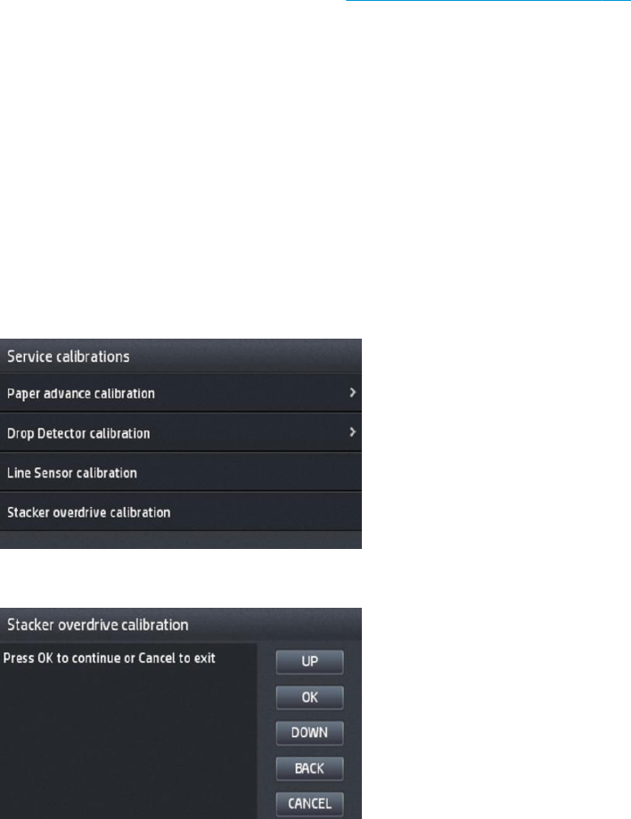
4. When you have loaded the paper, press OK. The product starts the calibration process, and displays the
results on the Front Panel if successful. Press OK to continue.
If the calibration fails, start again from the beginning. If necessary, try replacing the Line Sensor.
5. The Front Panel asks you to unload the paper. It then reminds you to reload roll paper in the normal way
and perform the full Line Sensor calibration (see The full calibration process on page 236).
Stacker overdrive calibration
The purpose of this Service Calibration is to calibrate the stacker overdrive friction against the printer.
It has to be done when:
●Reinstalling or replacing the complete stacker.
●When replacing the stacker overdrive motor with transmission part.
Follow these steps:
1. Prior to calibration, remove all the prints in the stacker and any paper loaded in the printer.
2. To select this calibration, go to 'stacker overdrive calibration':
3. After selecting it, press OK to start calibration.
238 Chapter 4 Diagnostics, Service Utilities and Calibrations ENWW
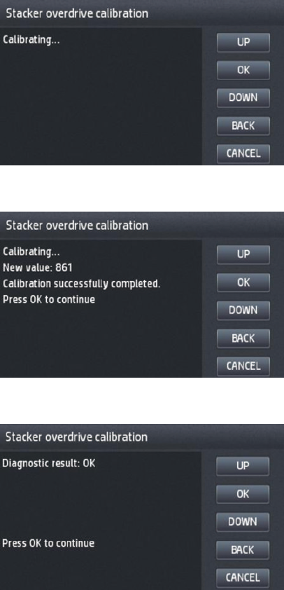
4. The screen will show 'calibrating status' during some minutes while the stacker overdrive is moving at
dierent speeds.
5. At the end of the process, the result of the calibration is shown.
6. Press OK to nish the calibration.
ENWW Service Calibrations 239

5 Parts and diagrams
●Introduction
●Printer support
●Center and Roll covers
●Rear covers
●Cover Front Panel Side
●Cover SVS Side
●Center Assemblies
●Front Panel Side Assemblies
●SVS Side Assemblies
●Scan Axis Assemblies
●Paper Path Assemblies (Front)
●Paper Path Assemblies (Center)
●Stacker Parts (Rear)
●Stacker Parts (Front)
●Carriage Assembly
●Electrical Parts
●Miscellaneous Parts
●CIS Unit Construction
●Scanner Control Unit
Introduction
The list of parts in this chapter include the notation CSR for parts that can be replaced by the customer. All other
parts must be replaced by an engineer. See Customer Self Repair parts on page 277.
For information on the preventive maintenance kits, see Preventive Maintenance Kits on page 472.
Unless otherwise indicated, service parts are compatible with all SKUs. Any limitations are indicated in the tables
below:
240 Chapter 5 Parts and diagrams ENWW
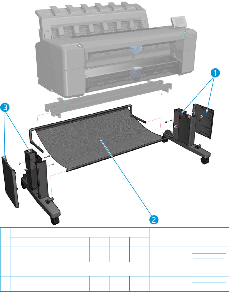
Printer support
Part number
Description Cross-referenceT920 T930 T1500 T1530 T2500 T2530 T3500
1 CR357-6
7064
N/A CR357-6
7064
N/A CR357-6
7064
N/A CR357-6
7064
Leg FP Side Assy W/
Cover
Customer Self Repair
Flyers on page 473
2 CR357-67066 Basket Assy Customer Self Repair
Flyers on page 473
3 CR357-6
7065
N/A CR357-6
7065
N/A CR357-6
7065
N/A CR357-6
7065
Leg SVS side Assy W/
C
Customer Self Repair
Flyers on page 473
ENWW Printer support 241
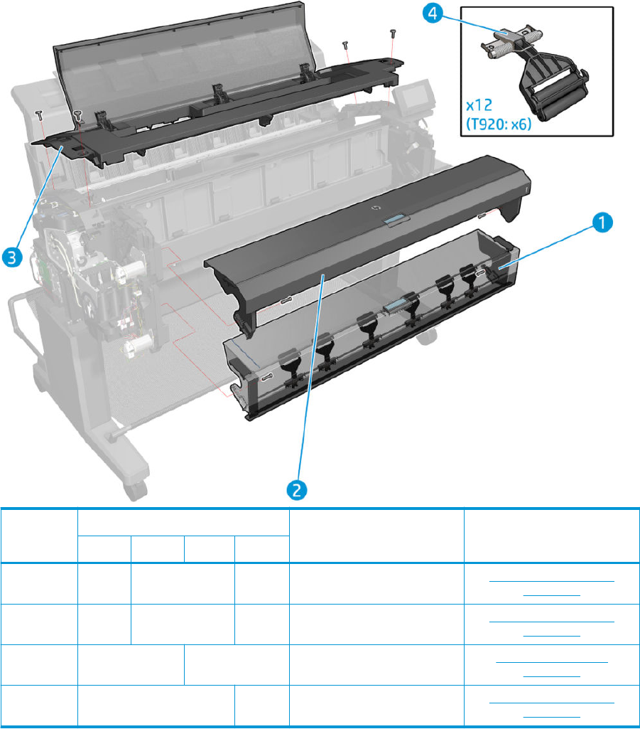
Center and Roll covers
Part number
Description Cross-referenceT9x0 T15x0 T25x0 T3500
1 N/A CR357-67036 B9E24-6
7003
Bottom Roll Cover Assy Customer Self Repair Flyers
on page 473
2 CR355-6
7001
CR357-67039 B9E24-6
7002
Top Roll Cover Assy Customer Self Repair Flyers
on page 473
3 CR357-67054 N/A Center Cover Assy Center cover (T920 only)
on page 285
4 CR357-67067 B9E24-6
7022
ARS Arm Assy Customer Self Repair Flyers
on page 473
242 Chapter 5 Parts and diagrams ENWW
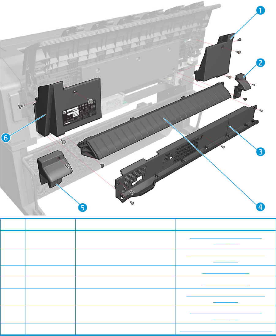
Rear covers
Part number Description Cross-reference
1 CR357-67061 Cover Fixed Tray SVS side Fixed tray cover (service station side)
on page 292
2 CR357-67063 Cover Sidewall SVS side Arch sidewall cover (service station side)
on page 294
3 CR357-67055 Rear Cover (T920, T1500 and T2500 only) Rear cover on page 295
N/A L2Y21-67007 Rear Cover (T930, T1530 only) Rear cover on page 295
4 CR357-67014 Output Platen Arch sidewall cover (service station side)
on page 294
5 CR357-67062 Cover Sidewall FP side Arch sidewall cover (front panel side)
on page 293
6 CR357-67060 Cover Fixed Tray FP side Fixed tray cover (Front Panel side) on page 291
ENWW Rear covers 243
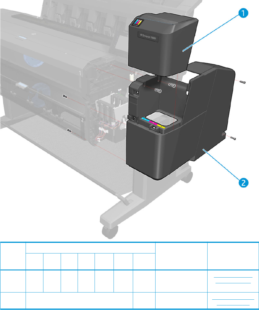
Cover Front Panel Side
Part number
Description Cross-referenceT920 T930
T150
0
T153
0 T2500 T2530 T3500
1 CR357
-6705
8
L2Y21
-6700
2
CR35
7-670
58
L2Y21
-6700
2
CR357-
67058
L2Y21-
67002
B9E24-6
7013
Ink Door FP side Customer Self Repair
Flyers on page 473
2 CR357-67059 B9E24-6
7011
Cover Main FP side Main cover (front panel
side) on page 281
244 Chapter 5 Parts and diagrams ENWW
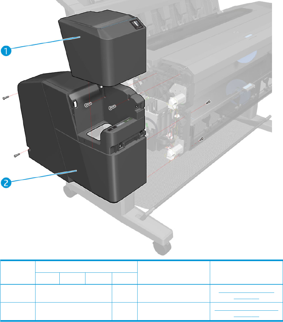
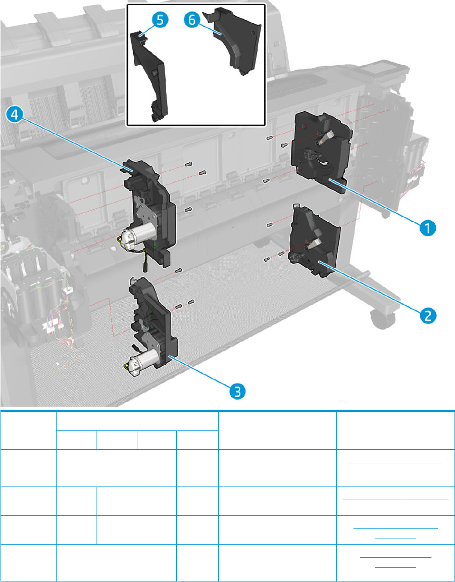
Center Assemblies
Part number
Description Cross-referenceT9x0 T15x0 T25x0 T3500
1 CR357-67038 B9E24-67
005
Top Tip Support Assy Top Tip Support on page 363
2 N/A CR357-67035 B9E24-67
010
Bottom Tip Support Bottom Tip Support on page 364
3 N/A CR357-67034 B9E24-67
009
Bottom Rewinder Support Bottom Rewinder Support
on page 359
4 CR357-67037 B9E24-67
004
Top Rewinder Support A Top Rewinder Support
on page 361
246 Chapter 5 Parts and diagrams ENWW

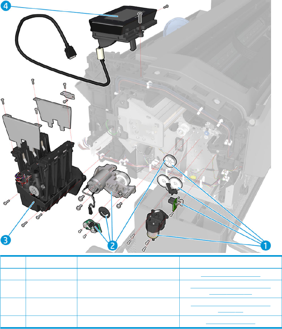
Front Panel Side Assemblies
Part number Description Cross-reference
1 CR357-67010 Starwheel Motor Starwheel Motor on page 387
2 CR357-67009 Motor Media Advance Transmission with
Encoder
Motor Media Advance Transmission with
Encoder on page 379
3 CR357-67028 ISS FP side ISS (Ink Supply Station) Front Panel Side
on page 346
4 CR357-67052 Front Panel Assy Front panel on page 318
248 Chapter 5 Parts and diagrams ENWW
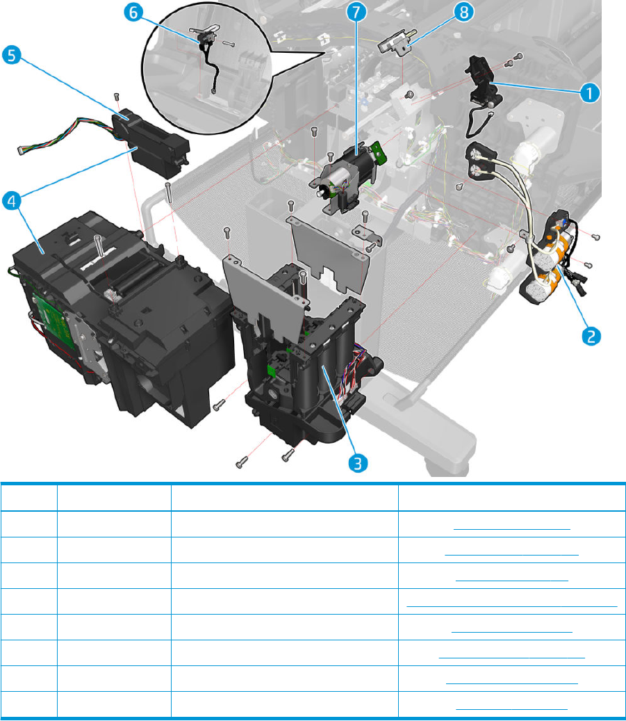
SVS Side Assemblies
Part number Description Cross-reference
1 CR357-67003 PRS Actuator PRS Actuator on page 330
2 CR357-67024 Primer Assy Primer Assembly on page 343
3 CR357-67029 ISS SVS side ISS SVS Side on page 350
4 CR357-67025 SVS W/ DD Service Station with Drop Detector on page 339
5 CR357-67026 Drop Detector Drop Detector on page 338
6 CR357-67080 microswitch (sensor) Stacker Arm Sensor on page 424
7 CR357-67005 Auto Pinch Lifter Assy Auto Pinch Lifter on page 370
8 Q6675-60043 Rail Oiler Rail Oiler Kit on page 329
ENWW SVS Side Assemblies 249
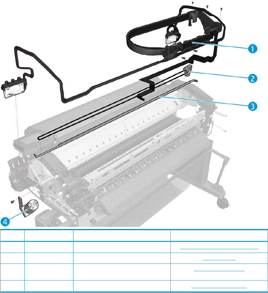
Scan Axis Assemblies
Part number Description Cross-reference
1 CR357-67027 Ink Tubes and Trailing Cable Ink Tubes and Trailing Cable on page 354
2 CR357-67021 Belt with Tensioner Belt on page 332
3 CR357-67022 Encoder Strip (for all machines except T15x0
Postscript printers CR357A and L2Y24A)
Encoder Strip on page 333
4 CR357-67023 Scan Axis Motor Scan Axis Motor on page 335
250 Chapter 5 Parts and diagrams ENWW
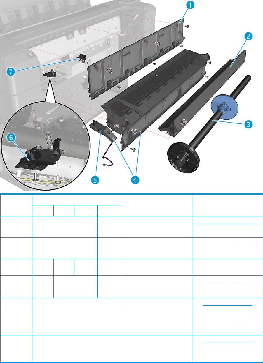
Paper Path Assemblies (Front)
Part number
Description Cross-referenceT9x0 T15x0 T25x0 T3500
1 CR357-67033 B9E24-6
7021
Vertical Media Guide A Vertical Media Guide on page 366
2 CR357-67032 B9E24-6
7008
Converger Assy Converger Assembly on page 287
3 CR357-
67093
CR357-
67093*
CR357-6
7040**
B9E24-6
7007
Spindle 36 Assy
4 CR354-
67006*
**
CR357-67030 B9E24-6
7006
Cleanout Assy Cleanout on page 288
5 CR357-67031 Media Sensor Media Sensor on page 357
6 CR357-67004 Pinch Wheel Assy Pinch Wheel Assembly
on page 376
7 CH538-67074 Center support Assy Center Support on page 368
ENWW Paper Path Assemblies (Front) 251
*For all T15x0 and printers except the T1530 Rev. B Postscript printer. For the following T25x0 printers: T2500
Rev. B Postscript printer; T2530 printer and T2530 Postscript printer.
**For the T2500 eMF and T2500 Postscript printer CR359A only. For the T2500 Rev. B Postscript Printer, T2530
eMF, and T2530 Postscript printers, use part number CR357-67093.
***For all T9x0 machines except the T930 Postscript printer CR355B.
252 Chapter 5 Parts and diagrams ENWW
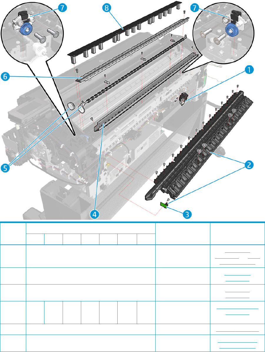
Paper Path Assemblies (Center)
Part number
Description Cross-referenceT920 T930 T1500 T1530 T2500 T2530 T3500
1 CR357-67015 Ramps and valves motor Ramps Motor
on page 422 and Valves
Motor on page 404
2 Old CR357-67013* / New L2Y24–67001** Cutter Platen Cutter Platten
on page 398
3 CR357-67006 Opto sensor OPTO Sensor
on page 417
4 CR357
-6701
6
CR357
-6709
8
CR357
-6701
6
CR357
-6709
8
CR357
-6701
6
CR357
-6709
8
CR357
-6701
6
2nd Starwheel Rail Second Starwheel Rail
on page 394
5 CR357-67011 Overdrive Overdrive on page 396
6 CR354-67004 36 Sheet Metal Starwheel Customer Self Repair
Flyers on page 473
ENWW Paper Path Assemblies (Center) 253

Part number
Description Cross-referenceT920 T930 T1500 T1530 T2500 T2530 T3500
7 CR357-67086 Starwheel Support Starwheel Support
on page 392
8 N/A CR357
-6700
2
CR357
-6700
2
CR357
-6700
2
Full Bleed Full Bleed on page 369
*For T2500 Rev. A printers only.
**Not for T2500 Rev. A printers.
254 Chapter 5 Parts and diagrams ENWW
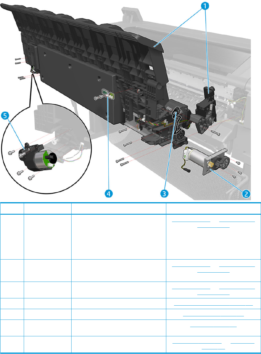
Stacker Parts (Rear)
Part number Description Cross-reference
1a CR354-67003 Stacker (Single Function CR354A, CR355A,
CR355B, CR356A, CR357A, CR357B, L2Y21A,
L2Y22A, L2Y22B, L2Y23A, L2Y24A, L2Y24B)
For T2500 MFP, part number CR359-67006
Stacker adaptor for MFP needs to be ordered
additionally
Stacker on page 405 and Stacker adaptor for
MFP on page 407
1b CR354-67003 &
CR359-67006
Stacker & T9x0/T15x0/T2500 Stacker Adaptor
for MFP (Multifunction CR358A, CR359A,
CR359B)
Stacker on page 405 and Stacker adaptor for
MFP on page 407
1c B9E24-67025 Stacker T3500 (Production eMFP B9E24A,
B9E24B)
Stacker on page 405 and Stacker adaptor for
MFP on page 407
2 CR357-67043 Stacker OVD Transmission W/ Motor OVD Transmission with Motor on page 420
3 CR357-67080 microswitch (sensor) Stacker Arm Sensor on page 424
4 CR357-67045 T920/T1500/T2500 REDI Sensor (removed
from T920/T1500 starting from SN 493xxxxx)
REDI sensor on page 419
5 CR357-67015 Ramps and valves motor Ramps Motor on page 422 and Valves Motor
on page 404
ENWW Stacker Parts (Rear) 255
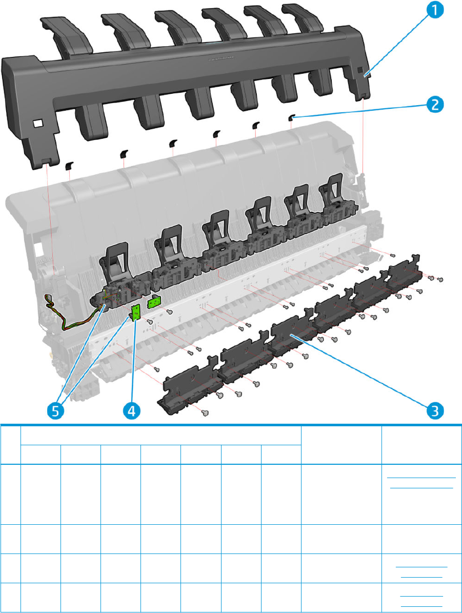
Stacker Parts (Front)
Part number
Description Cross-referenceT920 T930 T1500 T1530 T2500 T2530 T3500
1 CR357-6
7082
(CR354–
67002
old PN)
L2Y23-6
7006
CR357-6
7082
(CR354–
67002
old PN)
L2Y23-6
7006
CR357-6
7082
(CR354–
67002
old PN)
L2Y23-6
7006
L2Y23-6
7006
Stacker Arms Customer Self Repair
Flyers on page 473
2 CR357-6
7078
CR357-6
7078
CR357-6
7078
CR357-6
7078
CR357-6
7078
CR357-6
7078
CR357-6
7078
Stack Pad
3 CR357-6
7074
CR357-6
7074
CR357-6
7074
CR357-6
7074
CR357-6
7074
CR357-6
7074
CR357-6
7074
Stacker Pinches Stacker Pinches
on page 411
4 CR357-6
7006
CR357-6
7006
CR357-6
7006
CR357-6
7006
CR357-6
7006
CR357-6
7006
CR357-6
7006
Opto sensor OPTO Sensor
on page 417
256 Chapter 5 Parts and diagrams ENWW

Part number
Description Cross-referenceT920 T930 T1500 T1530 T2500 T2530 T3500
5a CR357-6
7041
CR357-6
7041
CR357-6
7041
CR357-6
7041
CR357-6
7041
CR357-6
7041
Stacker Hand O
(except T3500)
Stacker Hand O
Assy Service Kit
(CR357-67041)
on page 413
5b B9E24-6
7026
Stacker Hand O
(T3500 only)
Stacker Hand O
on page 412
Printing Graphics and High Density Images
Background
Under certain situations, when printing high density images to the stacker on light media (Coated, Plain paper),
the printer may report a jam that customers need to clear in order to continue printing. In some conditions like
high humidity, end of media roll, or paper with excessive curling, there may be an increased chance of this issue.
Conguring the printer to print graphics
In order to maximize printer productivity when printing graphic content, the following setup can be used:
1. Download the paper preset “Retail plain paper” from www.hp.com.
2. Upload the paper preset “Retail plain paper”. This media preset has been designed to optimize the Image
Quality / Speed / Cost per copy balance for indoor poster applications. It has an optimized ink usage in
Normal printing mode (so it prevents jams and reduces cost per copy). It also features a Fast mode with
better image quality than the “Bright White” paper preset, which is directed more at drawing applications.
3. Order the service kit CR357-67089 Stacker tray ller which gives a smoother stacker paper exit.
ENWW Printing Graphics and High Density Images 257

4. The printer should have the latest Stacker Arms design; make sure the printer has a Serial Number starting
with CN43 or SG43 in order to ensure so.
258 Chapter 5 Parts and diagrams ENWW
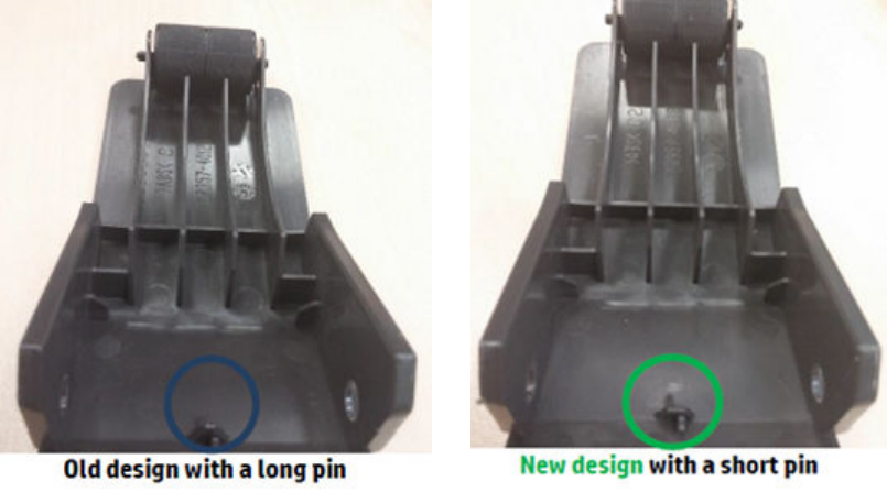
5. If the printer has the old design with the long pin, new CR357-67082 Stacker Arms can be ordered.
Other workarounds
For optimal graphics reproduction you might want to consider:
●Use Heavy Weight Coated paper. It has fewer cockles and more ink capacity, so when printing high density
graphics it performs better than plain and coated papers. Also it has better color.
●Media can be loaded as a paper with a lower ink limit to reduce ink usage and have fewer cockles, for
example: load Coated media as Plain Paper.
●In high humidity, try to maintain a drier environment.
●For Coated; 3” core rolls help to have less curling, and thus less jams.
ENWW Printing Graphics and High Density Images 259
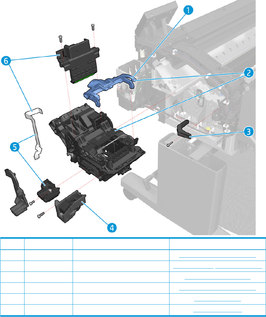
Carriage Assembly
Part number Description Cross-reference
1 CR357-67070 Carriage Latch Customer Self Repair Flyers on page 473
2 CR357-67081 Carriage W/O PCA / Line Sensor Carriage on page 322/Line Sensor on page 326
3 CR357-67068 Bump Cutter Actuator Bump Cutter Actuator on page 426
4 CR357-67007 Cutter X Customer Self Repair Flyers on page 473
5 CR357-67020 Line Sensor W/ Cable Line Sensor on page 326
6 CR357-67081 Carriage PCA w/ Line Sensor Cable Carriage PCA on page 327
260 Chapter 5 Parts and diagrams ENWW
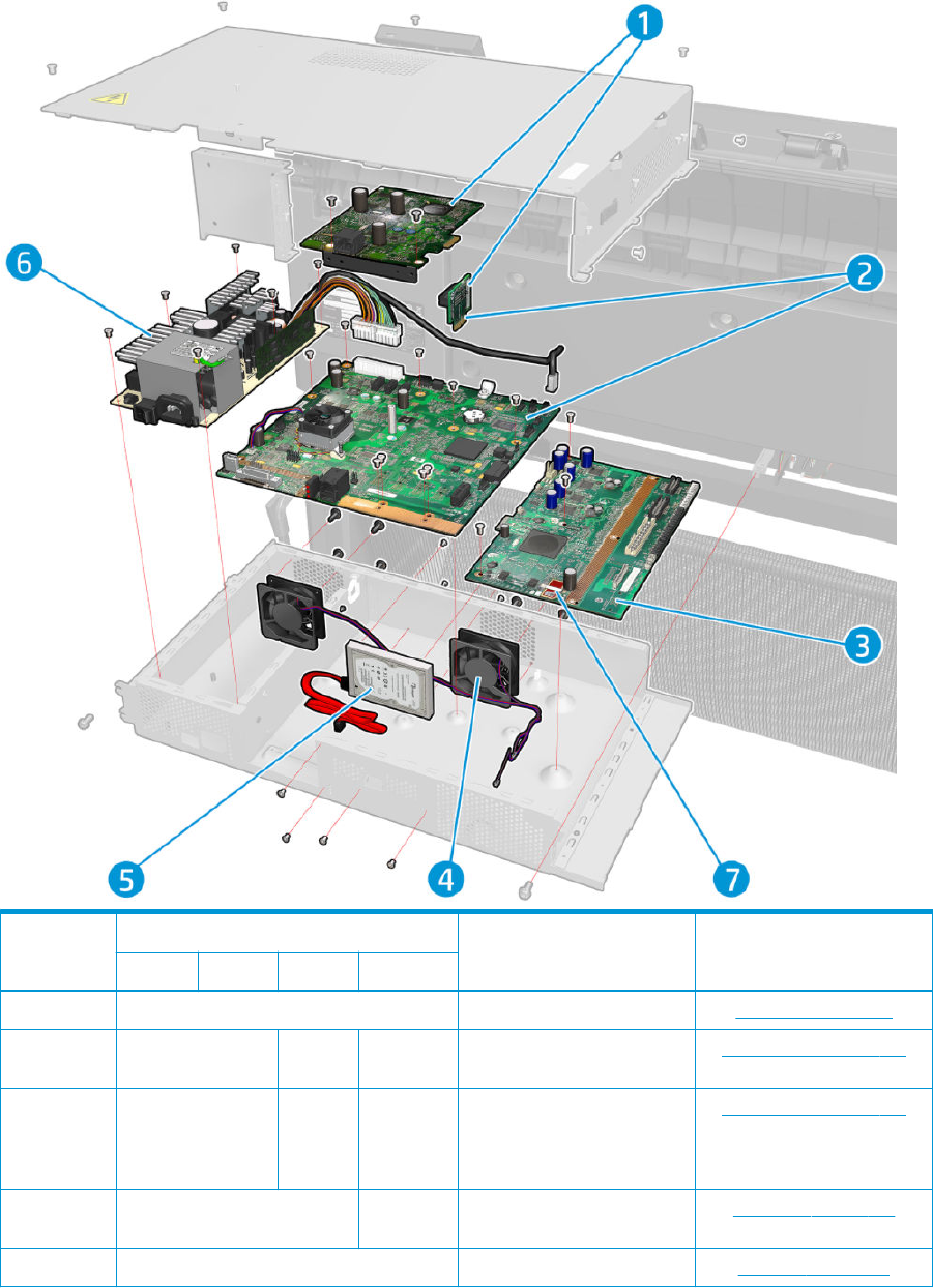
Electrical Parts
Part number
Description Cross-referenceT920 T1500 T2500 T3500
1 CR357-67050 Jester plus Riser Jester PCA on page 310
2a CR357-67051 CR359-6
7001
N/A Formatter Power W/ Riser (For
Rev.A models only)
Formatter PCA on page 315
2b CR357-67085 CR359-6
7031
B9E24-670
15
Formatter power w/ Riser and w/
HDD (for T920, T1500, T2500
only rev B models only, for
T3500 all (A and B)
Formatter PCA on page 315
3 CR357-67049 B9E24-670
17
Engine PCA Engine PCA on page 314
4 CR357-67048 E-Box Fan E-Box fan on page 308
ENWW Electrical Parts 261

Part number
Description Cross-referenceT920 T1500 T2500 T3500
5a CR357-67083 N/A HDD W/ FW (For Rev.A models
only)
Hard disk drive on page 313
5b CR357-67084 B9E24-670
18
HDD Encrypted w/ FW (for T920,
T1500, T2500 only rev B models
only, for T3500 all (A and B)
Hard disk drive on page 313
6 CR357-67046 PSU Power supply unit on page 311
7 CR357-67087 B9E24-670
23
CryptoAsic SIM
Part number
DescriptionT930 T1530 T2530
1 CR357-67050 Jester plus Riser
2a CR357-67051 CR359-67001 Formatter Power W/ Riser (For Rev.A models only)
2b L2Y22-67006 L2Y26-67003 Formatter power w/ Riser and w/ HDD (ForRev.B
models only)
3 CR357-67049 Engine PCA
4 CR357-67099 E-Box Fan
5a L2Y21-67004
(320GB)
L2Y23-67005 (500GB) HDD W/ FW (For Rev.A models only)
5b L2Y22-67004 HDD Encrypted w/ FW (For Rev.B models only)
6 CR357-67046 PSU
7 B9E24-67023 CryptoAsic SIM
262 Chapter 5 Parts and diagrams ENWW

Miscellaneous Parts
Part number Description
CR354-67005 Support Label T920 Nameplate
L2Y21-67003 Support Label T930 Nameplate
L2Y21-67006 T9XX/T15XX/T25XX Rear Beam SV
CR355-67006 Support Label T920PS Nameplate
CR355-67007 Support LBL US Gov T920PS Nameplate
L2Y22-67001 Support Label T930PS Rev A. printer Nameplate
L2Y22-67003 Support LBL US Gov T930PS Nameplate
CR356-67001 Support Label T1500 Nameplate
CR357-67076 Support Label T1500PS Nameplate
CR357-67077 Support LBL US Gov T1500PS Nameplate
CR357-67094 T9x0/Tx500 Stand
L2Y23-67004 Support LBL T1530 Nameplate
L2Y24-67002 Support Label T1530PS Rev A. printer Nameplate
L2Y24-67003 Support LBL US Gov T1530PS Nameplate
CR358-67001 Support Label T2500 Nameplate
CR359-67028 Support Label T2500PS Nameplate
CR359-67027 Support LBL US Gov T2500PS Nameplate
L2Y25-67002 Support Label T2530 Nameplate
L2Y26-67001 Support Label T2530PS Rev A. printer Nameplate
L2Y26-67002 Support LBL US Gov T2530PS Nameplate
CR359-67032 Serial Label for:
●T25x0 Rev. A printers
CQ533-60001 Europe Power Cord KIT for
●T9x0 Rev.A printers
●T15x0 Rev.A printers
●T25x0 Rev.A printers
CQ533-60002 America Power Cord KIT
CQ533-60003 Asia Power Cord KIT for:
●T9x0 Rev.A printers
●T15x0 Rev.A printers
●T25x0 Rev.A printers
CR357-67053 Product Cables for T15x0, T25x0 printers
ENWW Miscellaneous Parts 263

Part number Description
CR357-67072 PM Kit-1
CR357-67073 PM Kit-2
CR357-67075 Serial Label for:
●T920 printers
●T930 Rev. A printers
●T1500 Rev. A printers
●T1530 Rev. A printers
CR357-67079 Paper Advance Calibration
CR355-67002 1R Cables Kit for T9x0 printers
264 Chapter 5 Parts and diagrams ENWW
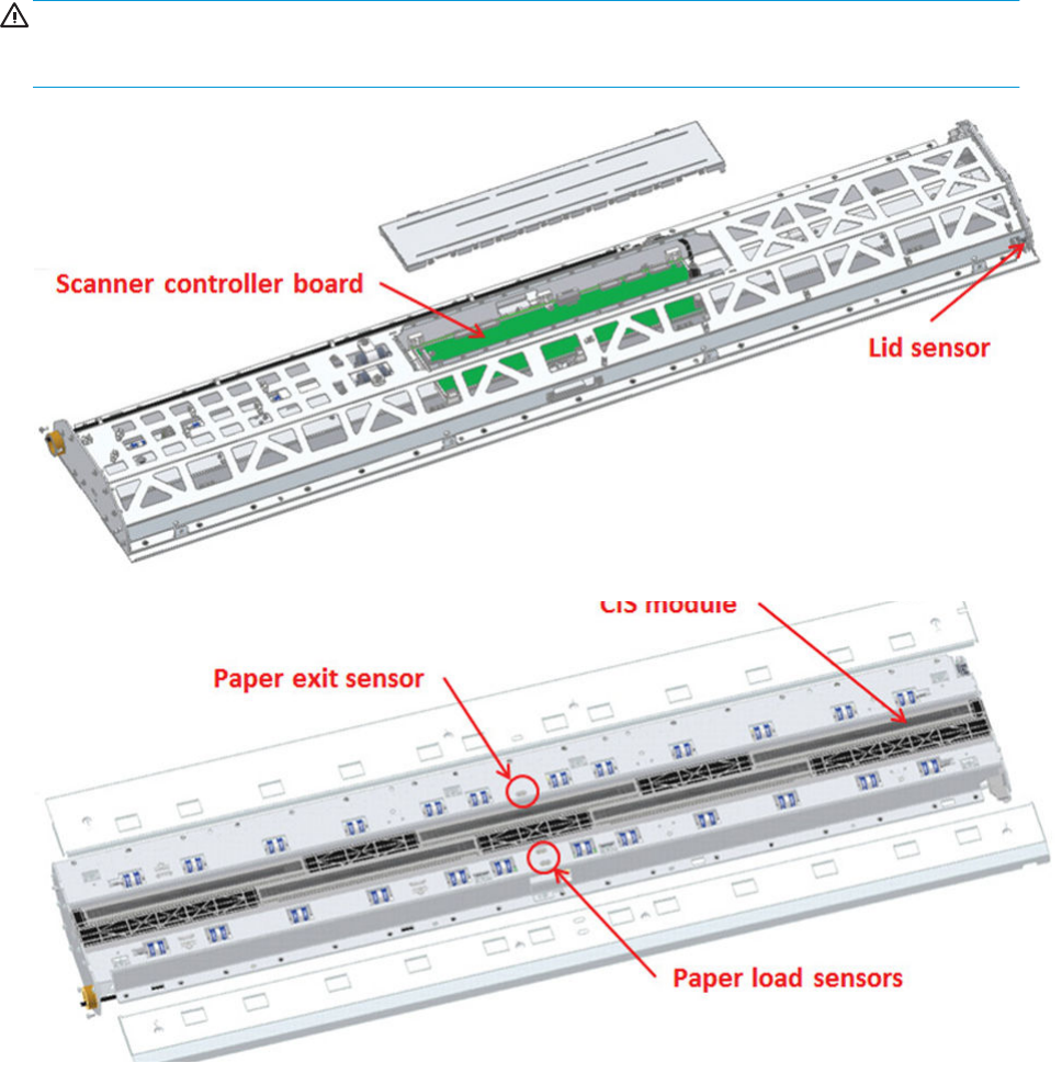
CIS Unit Construction
WARNING! The CIS unit is factory mounted and must not be Disassembled further than replacing the scanner
control unit, paper/lid sensors, glass plate and USB cable. Ignoring this warning may cause failures that can not
be corrected in the eld.
ENWW CIS Unit Construction 265
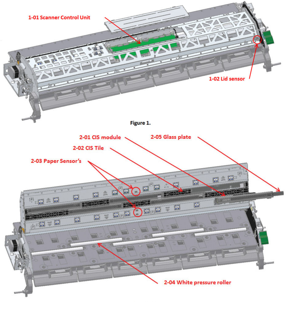
Scanner Control Unit
266 Chapter 5 Parts and diagrams ENWW
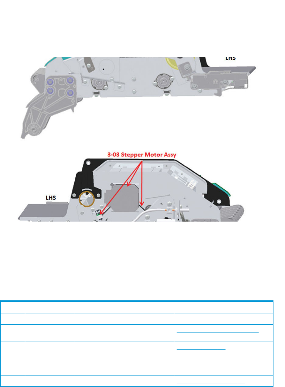
Service Parts
Part number Description Cross-reference
1-01a CR359-67023 Scanner Controller Unit (except T3500) Scanner Controller Unit (SUP) on page 430
1-01b B9E24-67020 Scanner Controller Unit (T3500 and compatible
with T2500)
Scanner Controller Unit (SUP) on page 430
2-01 CR359-67024 CIS Module Assembly CIS Modules on page 432
2-01 CR359-67033 T25x0/T3500 CIS module 5x unit CIS Modules on page 432
N/A CR359-67015 FFC Cable Set-Scanner for T25x0 printers CIS FFC Cables on page 433
2-03 CR359-67018 Paper/Lid Sensor (1 pcs.) for T25x0 printers Paper and Lid Sensors on page 438
ENWW Scanner Control Unit 267

Part number Description Cross-reference
3-03 CR359-67016 Stepper Motor Assembly (including taco sensor)
for T25x0 printers
Stepper Motor Assembly (taco sensor, and belt)
on page 435
N/A CR359-67021 Scanner USB & Power/Reset/Awake Cable for
T25x0 printers
USB & Awake / Power Cable on page 441
3-01 CR359-67019 Damper Assembly for CIS Bridge for T25x0
printers 3500
CIS Bridge Damper on page 443
2-04 CR359-67017 Pressure Rollers (X pcs.) for T25x0 printers
3500
Pressure Rollers on page 446
3-02 CR359-67012 Latch CIS for T25x0 printers CIS Scanner Latch on page 445
N/A CR359–67003 RHS Cover Front panel side scanner cover on page 447
N/A CR359-67004 Cover Service Station Side for T25x0 printers Service station side scanner cover on page 448
N/A CR359-67005 Cover Scanner Rear SV for T25x0 printers Rear scanner cover on page 449
N/A CR359-67006 Stacker adaptor for MFP Stacker adaptor for MFP on page 407
N/A CR359-67007 Scanner Bumper bracket Assy SV for T25x0
printers
Bumper bracket on page 450
N/A CR359-67008 Scanner Deectors SV for T25x0 printers Deector hinge on page 451
N/A CR359-67009 Scanner Lift Assy SV for T25x0 printers Lift assembly on page 452
N/A CR359-67010 Scanner Front Beam Bumper Assy for T25x0
printers
Scanner front beam bumper assembly
on page 453
N/A CR359-67011 Scanner Latch Hook Assy Push SV for T25x0
printers
Scanner latch hook assembly on page 454
N/A CR359-67025 Top Cover scanner (except T2500 only) Scanner front beam bumper assembly
on page 453
N/A L2Y25-67004 Top Cover scanner (T2530 only) Scanner front beam bumper assembly
on page 453
N/A B9E24-67019 Top Cover scanner (T3500 only) Top scanner cover on page 455
N/A CR359-67003 Cover scanner CP_side (RHS Cover) for T25x0
printers
N/A B9E24-67001 T3500 Batch Scanner Roller SV Batch scanning piece on page 456
268 Chapter 5 Parts and diagrams ENWW


Parts list; all models
Parts in alphabetical order Parts in removal order
Arch sidewall cover (front panel side) on page 293 Main cover (front panel side) on page 281
Arch sidewall cover (service station side) on page 294 Main cover (service station side) on page 283
Auto Pinch Lifter on page 370 Center cover (T920 only) on page 285
Belt on page 332 Converger Assembly on page 287
Bottom Rewinder Support on page 359 Cleanout on page 288
Bottom Tip Support on page 364 Output platen on page 290
Bump Cutter Actuator on page 426 Fixed tray cover (Front Panel side) on page 291
Carriage on page 322 Fixed tray cover (service station side) on page 292
Carriage PCA on page 327 Arch sidewall cover (front panel side) on page 293
Center cover (T920 only) on page 285 Arch sidewall cover (service station side) on page 294
Center Support on page 368 Rear cover on page 295
Cleanout on page 288 Window Sensor on page 296
Converger Assembly on page 287 HP 727 Printhead installation tips and tricks on page 298
Cutter Platten on page 398 Ink Service kit on page 303
Drop Detector on page 338 Open the E-Box on page 304
E-Box fan on page 308 E-Box fan on page 308
Engine PCA on page 314 Jester PCA on page 310
Fixed tray cover (Front Panel side) on page 291 Power supply unit on page 311
Fixed tray cover (service station side) on page 292 Hard disk drive on page 313
Formatter PCA on page 315 Engine PCA on page 314
Front panel on page 318 Formatter PCA on page 315
Full Bleed on page 369 Front panel on page 318
Hard disk drive on page 313 Carriage on page 322
How to manually move Stacker Ramps on page 429 Line Sensor on page 326
How to manually move Valves on page 428 Carriage PCA on page 327
How to release Service Station Caps on page 427 Rail Oiler Kit on page 329
HP 727 Printhead installation tips and tricks on page 298 PRS Actuator on page 330
Ink Service kit on page 303 Belt on page 332
Ink Tubes and Trailing Cable on page 354 Encoder Strip on page 333
ISS (Ink Supply Station) Front Panel Side on page 346 Scan Axis Motor on page 335
ISS SVS Side on page 350 Drop Detector on page 338
Jester PCA on page 310 Service Station with Drop Detector on page 339
Line Sensor on page 326 Primer Assembly on page 343
Encoder Strip on page 333 ISS (Ink Supply Station) Front Panel Side on page 346
270 Chapter 6 Removal and installation ENWW

Parts in alphabetical order Parts in removal order
Main cover (front panel side) on page 281 ISS SVS Side on page 350
Main cover (service station side) on page 283 Ink Tubes and Trailing Cable on page 354
Media Sensor on page 357 Media Sensor on page 357
Motor Media Advance Transmission with Encoder on page 379 Bottom Rewinder Support on page 359
Open the E-Box on page 304 Top Rewinder Support on page 361
OPTO Sensor on page 417 Top Tip Support on page 363
OVD Transmission with Motor on page 420 Bottom Tip Support on page 364
Output platen on page 290 Vertical Media Guide on page 366
Overdrive on page 396 Center Support on page 368
Pinch Wheel Assembly on page 376 Full Bleed on page 369
Power supply unit on page 311 Auto Pinch Lifter on page 370
Primer Assembly on page 343 Pinch Wheel Assembly on page 376
PRS Actuator on page 330 Motor Media Advance Transmission with Encoder on page 379
Rail Oiler Kit on page 329 Starwheel Motor on page 387
Ramps Motor on page 422 Starwheel Support on page 392
Rear cover on page 295 Second Starwheel Rail on page 394
REDI sensor on page 419 Overdrive on page 396
Scan Axis Motor on page 335 Cutter Platten on page 398
Second Starwheel Rail on page 394 Sensor Valves on page 401
Sensor Valves on page 401 Valves Motor on page 404
Service Station with Drop Detector on page 339 Stacker on page 405
Stacker on page 405 Stacker Pinches on page 411
Stacker Arm Sensor on page 424 Stacker Hand O on page 412
Stacker Hand O on page 412 OPTO Sensor on page 417
Stacker Pinches on page 411 REDI sensor on page 419
Starwheel Motor on page 387 OVD Transmission with Motor on page 420
Starwheel Support on page 392 Ramps Motor on page 422
Top Tip Support on page 363 Stacker Arm Sensor on page 424
Top Rewinder Support on page 361 Bump Cutter Actuator on page 426
Valves Motor on page 404 How to release Service Station Caps on page 427
Vertical Media Guide on page 366 How to manually move Valves on page 428
Window Sensor on page 296 How to manually move Stacker Ramps on page 429
ENWW Parts list; all models 271

Parts list; HP Designjet T2500 and T3500 eMultifunction Series only
NOTE: Before replacing any electrical parts such as the Scanner Control Unit, or Cameras, try calibrating the
scanner in order to get the scanner to recreate the content of the parameter block. This will solve the problem in
most cases.
Parts in alphabetical order Parts in removal order
Bumper bracket on page 450 Stacker adaptor for MFP on page 407
CIS Bridge Damper on page 443 Stacker Hand O Assy Service Kit (CR357-67041) on page 413
CIS FFC Cables on page 433 Scanner Controller Unit (SUP) on page 430
CIS Glass on page 434 CIS Tiles on page 431
CIS Modules on page 432 CIS Modules on page 432
CIS Scanner Latch on page 445 CIS FFC Cables on page 433
CIS Tiles on page 431 CIS Glass on page 434
Deector hinge on page 451 Stepper Motor Assembly (taco sensor, and belt) on page 435
Front panel side scanner cover on page 447 Stepper Motor Assembly (cable) on page 437
Lift assembly on page 452 Paper and Lid Sensors on page 438
Paper and Lid Sensors on page 438 Paper and Lid Sensor Cable on page 440
Paper and Lid Sensor Cable on page 440 USB & Awake / Power Cable on page 441
Pressure Rollers on page 446 CIS Bridge Damper on page 443
Rear scanner cover on page 449 CIS Scanner Latch on page 445
Scanner Controller Unit (SUP) on page 430 Front panel side scanner cover on page 447
Scanner front beam bumper assembly on page 453 Service station side scanner cover on page 448
Scanner latch hook assembly on page 454 Rear scanner cover on page 449
Service station side scanner cover on page 448 Bumper bracket on page 450
Stacker adaptor for MFP on page 407 Deector hinge on page 451
Stacker Hand O Assy Service Kit (CR357-67041) on page 413 Lift assembly on page 452
Stepper Motor Assembly (cable) on page 437 Scanner front beam bumper assembly on page 453
Stepper Motor Assembly (taco sensor, and belt) on page 435 Scanner latch hook assembly on page 454
Top scanner cover on page 455 Top scanner cover on page 455
272 Chapter 6 Removal and installation ENWW


Introduction
This chapter is a step-by-step guide to removal and installation of the key components of the product. It may be
useful to check o the steps as they are performed. Use the illustrations for each procedure to identify the parts
referred to in the text.
Some of the procedures have a video available which can be downloaded. When a video is available the following
graphic is shown:
Click on the graphic to download the video. These videos and others, are also available from the Service Media
Library.
●Employees and contingent workers: http://thesml.hp.com
●HP Channel partners, external call centers (requires registration): http://h20181.www2.hp.com/plm
●HP Customers: http://www.hp.com/go/sml
NOTE: Before using this chapter to remove and install a new component, always make sure that you have
performed the relevant service test. If the test passes you will not need to replace the component.
Safety Precautions
Review the instructions identied by WARNING and CAUTION symbols before servicing the product. Follow these
warnings and cautions for protection and to avoid damaging the product.
NOTE: Serious shock hazard leading to death or injury may result if you do not take the following precautions:
●Ensure that the AC power outlet (mains) has a protective earth (ground) terminal.
●Switch the product o, and disconnect it from the power source prior to performing any maintenance.
●Prevent water or other liquids from running onto electrical components or circuits, or through openings in
the module.
Electrostatic Discharge (ESD) Precautions
To prevent damage to the product's circuits from high-voltage electrostatic discharge (ESD):
1. Do not wear clothing that is subject to static build-up.
2. Do not handle integrated circuits (ICs) in carpeted areas.
3. Do not remove an IC or a printed circuit assembly (PCA) from its conductive foam pad or conductive
packaging until you are ready to install it.
4. Ground (earth) your body while disassembling and working on the product. 202 Chapter 6 Removal and
Installation ENWW.
5. After removing a cover from the product, attach an earthing (ground) lead between the PCA common and
earth ground. Touch all tools to earth ground to remove static charges before using them on the product.
6. After removing any PCA from the product, place it on a conductive foam pad or into its conductive
packaging to prevent ESD damage to any ICs on the PCA.
ENWW Introduction 275

Required Tools
All the special tools and equipment required to disassemble, service and repair the product are provided in the
Toolkit. Some tools can be ordered separately from the toolkit.
Toolkit Q6683-67001 contains the following tools:
Description/Comments HP Part Number
Alcohol Q6675-60091
Allen Key #2 Q6675-60041
Cleaning Cloth 9300-2531
Lubricant Oil Q6675-60061 (included in "Lubrication kit Q5669-60692" as well)
Oil Dispenser Q6675-60062 (included in "Lubrication kit Q5669-60692" as well)
Spring Insertion Tool Q5669-20594
Protective Plastic Gloves Q6675-60035 (included in "Lubrication kit Q5669-60692" as well)
Screwdriver 8710-2456
Tweezers Q6675-60037
T Series Cleaning Assembly C6071-60218
You will also need the following standard hand tools:
Description/Comments Size
Long Torx Screwdriver 1/4 inch drive
Torx Bit (75 mm) magnetic end 8/9/10 straight, 15/20 straight and angled
Philips Screwdriver PH1
Pliers N/A
Snips N/A
Flat-bladed Screwdriver N/A
Pipe Spanner 5.5 mm
Wrench 7.0 mm
Long Torx Screwdriver 1/4 inch drive
276 Chapter 6 Removal and installation ENWW

Customer Self Repair parts
Some product parts are designated Customer Self Repair (CSR) parts, which means that a faulty part can be
replaced by the customer. Non-CSR parts need to be replaced by an engineer.
The CSR parts are listed below:
Part number Description Flier
CR354-67004 Starwheel Yes
CR357-67007 Cutter Yes
CR354-67002 Stacker Arm Yes
CR357-67057 Ink cover, service-station side (except T3500) Yes
B9E24-67014 Ink cover, service-station side (T3500 only) Yes
CR357-67058 Ink cover, front-panel side (except T3500) Yes
B9E24-67013 Ink cover, front-panel side (T3500 only) Yes
CR357-67064 Leg, front-panel side Yes
CR357-67065 Leg, service-station side Yes
CR357-67036 Bottom roll cover (except T3500) Yes
B9E24-67003 Bottom roll cover (T3500 only) Yes
CR355-67001 /
CR357-67039
Top roll cover (except T3500) Yes
B9E24-67002 Top roll cover (T3500 only) Yes
CR357-67070 Carriage latch Yes
CR357-67066 Basket Yes
CR357-67067 Pinch arm top roll (except T3500) Yes
B9E24-67022 Pinch arm top roll (T3500 only) Yes
CR359-67014 CIS Tiles Kit for T25x0 printers No
CR359-67020 Glass Plate Assembly for T25x0 printers Yes
CN727-69006 Calibration Sheet for T25x0 printers No
For further information
●CSR Corporate Standards: http://standards.corp.hp.com/smc/hpstd/AHP0001501.htm
●CSR Web site: http://www.hp.com/go/csrparts/
●Part Surfer: http://partsurfer.hp.com/search.aspx
●HP Parts Page: http://partpage.corp.hp.com/default.asp
ENWW Customer Self Repair parts 277

Service Calibration Guide to Removal and Installation
Using the Service Calibration Guide
When you remove most product components, you will need to perform a particular set of Service Calibrations
and Diagnostic tests to ensure proper product performance.
The Service Calibration Table explains which service calibrations and diagnostic tests need to be performed
whenever you remove and install particular product components.
The calibrations and tests must be performed in the order in which they are listed.
NOTE: Even if you do not replace the removed component with a new component, you still need to perform the
calibrations indicated in the table.
Diagnostics and Calibration Table
Component Diagnostic Tests Calibrations Service Utilities
Auto Pinch Lifter Pinches lifter — —
Belt Scan Axis / Scan Axis — After replacement, reset "scan axis
belt"usage counters
Bump Cutter
Actuator
Scan Axis / Cutter. — —
Carriage
Assembly
Carriage Assembly, Scan Axis /Scan
Axis, Scan Axis / Cutter
Line Sensor Calibration After replacement, reset "carriage"
usage counters
Carriage PCA Carriage Assembly Line Sensor Calibration —
Center support Paper Drive Paper Advance Calibration —
Cutter Scan Axis / Cutter — —
Cutter platen -
Output Valves
Output Valve, Scan Axis / Cutter Output Valve Calibration, Line Sensor
Calibration
—
Drop Detector — Before replacement, run Drop
Detector Calibration / Reset
Calibration Flag. After replacement,
run Drop Detector Calibration /
Calibrate Drop Detector
After replacement, reset "drop
detector working time" usage
counters
Encoder Strip Scan Axis / Scan Axis — —
Formatter PCA,
Hard Disk Drive,
Engine PCA,
Jester PCA, Front
Panel, Power
Supply Unit, PSU
Fan
Electronics Module — —
Full Bleed Foams — — After replacement, reset "full bleed
foams" usage counters
Ink Supply
Station Front
Panel Side
Ink Delivery System — —
Ink Supply
Station SVS side
Ink Delivery System — —
278 Chapter 6 Removal and installation ENWW

Component Diagnostic Tests Calibrations Service Utilities
Ink Tubes and
Trailing Cable
Scan Axis / Scan Axis, Ink Delivery
System
— After replacement, reset "tubes and
trailing cable" usage counters
Line Sensor Carriage Assembly Line Sensor Calibration —
Motor Media
Advance
Transmission
with Encoder
Paper Drive Paper Advance Calibration —
Overdrive Paper Drive — —
Pinch Rollers Paper Drive — —
Preventative
Maintenance #1
Carriage Assembly, Scan Axis / Scan
Axis, Scan Axis / Cutter
Line Sensor Calibration After replacement, reset "Life PMK1"
counters
Preventative
Maintenance #2
Service Station, Carriage Assembly Before replacement, run Drop
Detector Calibration / Reset
Calibration Flag. After replacement,
run Drop Detector Calibration /
Calibrate Drop Detector. Line Sensor
Calibration
After replacement, reset "Life PMK2"
counters
Primers Service Station / Primer motor — —
PRS Actuator Scan Axis / PRS — —
Rail Oiler Scan Axis / Scan Axis — —
Scan Axis motor Scan Axis / Scan Axis — After replacement, reset "scan
motor" usage counters
Stacker (w/o
Arms assy)
Stacker Overdrive, Stacker Ramps Stacker Overdrive Calibration, Output
Valve Calibration
—
Stacker Arm
sensor
(microswitch)
Sensors — —
Stacker capacity
sensor (opto)
Stacker capacity sensor — —
Stacker jam
sensor (opto)
Stacker jam sensor — —
Stacker OVD
Transmission W/
Motor
Stacker Overdrive Stacker Overdrive Calibration —
Stacker Ramps
Motor
Stacker Ramps — —
Stacker REDI
Sensor
Stacker Empty Sensor — —
Stacker Valves
motor
Output Valve Output Valve Calibration, Line Sensor
Calibration
—
Stacker Valves
sensor
Output Valve Output Valve Calibration, Line Sensor
Calibration
—
Starwheel lifter
mech
Scan Axis / Starwheel Lifter – —
ENWW Service Calibration Guide to Removal and Installation 279

Component Diagnostic Tests Calibrations Service Utilities
Starwheel
supports
Scan Axis / Starwheel Lifter — —
SVS W/ Drop
Detector
Service Station Before replacement, run Drop
Detector Calibration / Reset
Calibration Flag. After replacement,
run Drop Detector Calibration /
Calibrate Drop Detector
After replacement, reset ""SVS""
usage counters. After replacement,
reset ""drop detector working time""
usage counters
Top or Bottom
Rewinder
Rewinder — —
Upper or Lower
Roll Cover
Sensor
(microswitch)
Sensors — —
Window Position
Sensor
(microswitch)
Sensors — —
280 Chapter 6 Removal and installation ENWW

Main cover (front panel side)
Removal
1. Remove 2 T-15 screws.
2. Remove 2 T-15 screws.
3. Open the ink cartridge cover.
ENWW Main cover (front panel side) 281
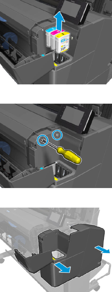
4. Remove the ink cartridges.
5. Remove 2 T-15 screws.
6. Remove the cover.
282 Chapter 6 Removal and installation ENWW
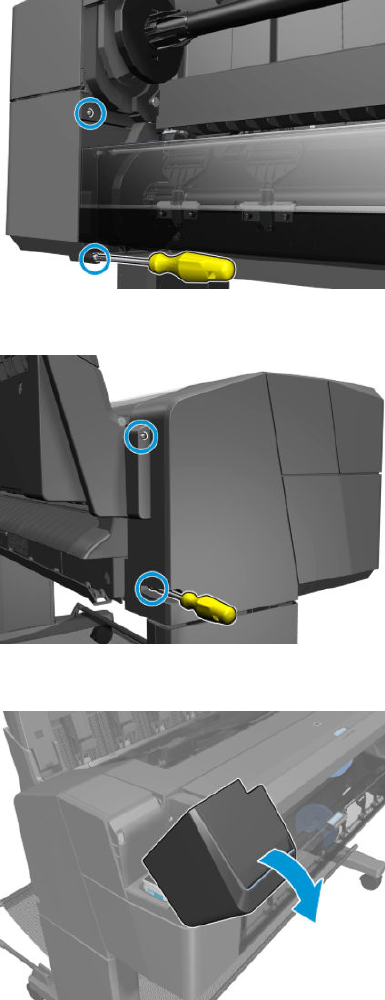
Main cover (service station side)
Removal
1. Remove 2 T-15 screws.
2. Remove 2 T-15 screws.
3. Open the ink cartridge cover.
ENWW Main cover (service station side) 283
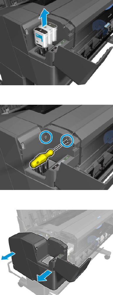
4. Remove the ink cartridges.
5. Remove 2 T-15 screws.
6. Remove the cover.
284 Chapter 6 Removal and installation ENWW
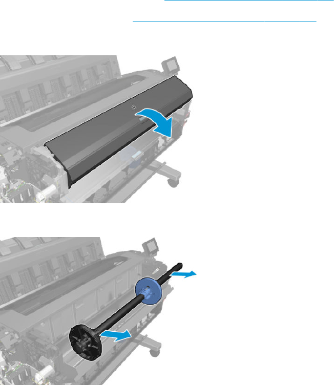
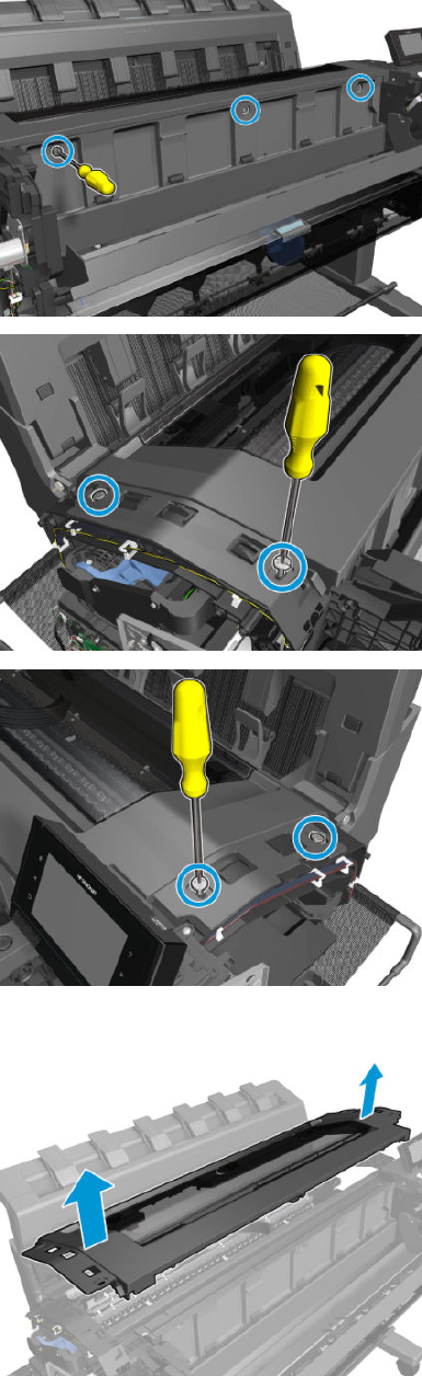
5. Remove the 7 T-15 screws.
6. Lift up the center cover, and remove It from the printer.
286 Chapter 6 Removal and installation ENWW
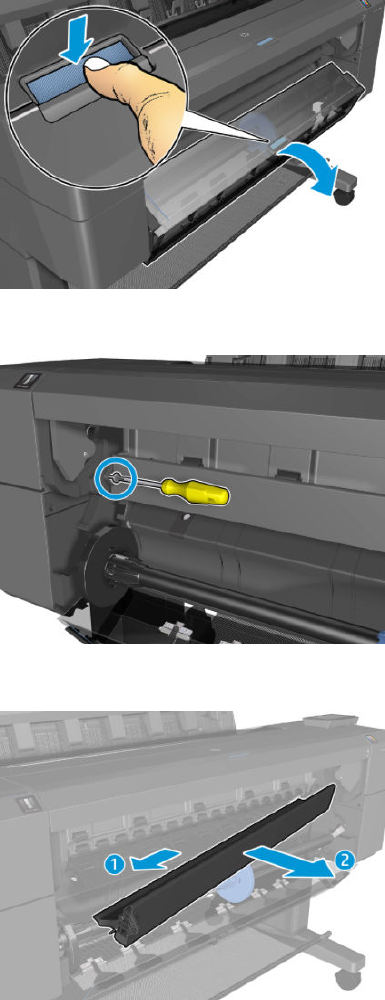
Converger Assembly
Removal
1. Remove the top spindle and close the top cover.
2. Open the bottom roll cover.
3. Remove the T-15 screw.
4. Remove the converger.
ENWW Converger Assembly 287
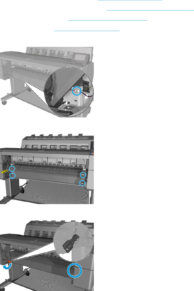
Cleanout
Removal
1. (T3500 only) Remove the bottom tip support. See Bottom Tip Support on page 364.
2. (T3500 only) Remove the control panel side cover. See Main cover (service station side) on page 283.
3. Remove the bottom roll cover. See Customer Self Repair Flyers on page 473.
4. Remove the converger. See Converger Assembly on page 287.
5. Disconnect the media sensor cable underneath the printer.
6. Remove 4 T-15 cosmetic screws.
7. Rotate the 2 supports outward.
288 Chapter 6 Removal and installation ENWW
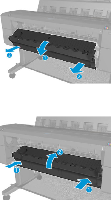
8. Remove the cleanout.
Installation
▲Insert at an angle, and when in, rotate upwards.
ENWW Cleanout 289
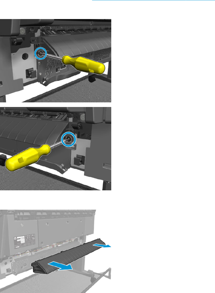
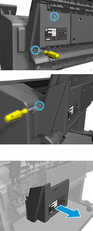
Fixed tray cover (Front Panel side)
Removal
1. Remove 3 cosmetic T-15 screws.
2. Remove the xed tray cover from the front panel side.
ENWW Fixed tray cover (Front Panel side) 291
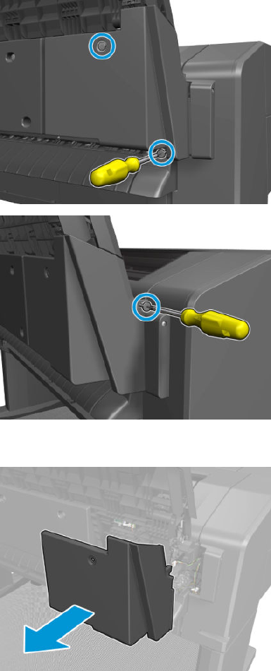
Fixed tray cover (service station side)
Removal
1. Remove 3 cosmetic T-15 screws.
2. Remove the xed tray cover from the service station side.
292 Chapter 6 Removal and installation ENWW
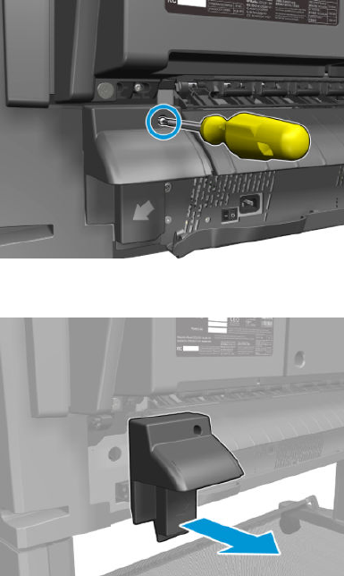
Arch sidewall cover (front panel side)
Removal
1. Remove the T-15 screw.
2. Remove the arch sidewall cover from the front panel side.
ENWW Arch sidewall cover (front panel side) 293
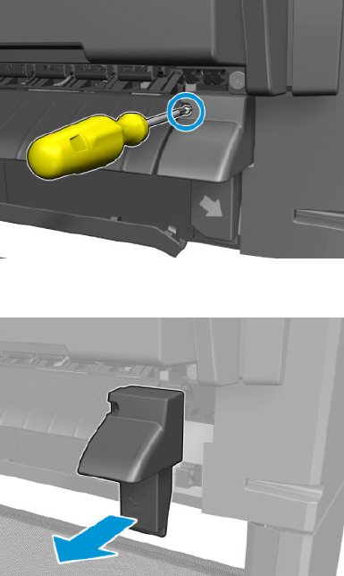
Arch sidewall cover (service station side)
Removal
1. Remove the T-15 screw.
2. Remove the arch sidewall cover from the service station side.
294 Chapter 6 Removal and installation ENWW
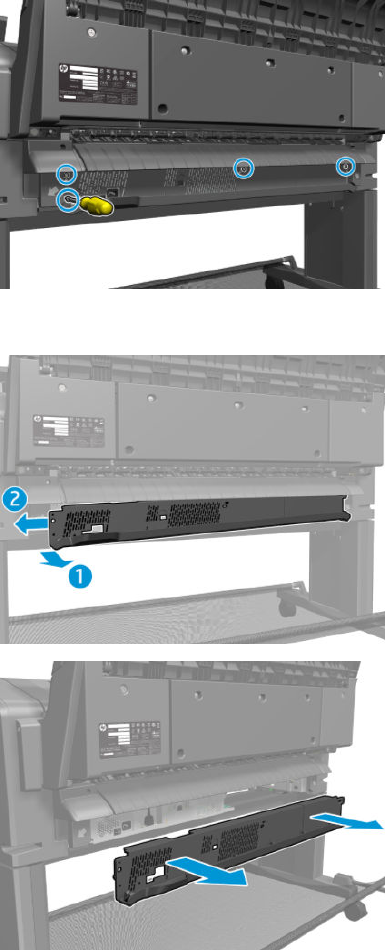
Rear cover
Removal
1. Remove 4 T-15 screws.
2. Remove the rear cover.
ENWW Rear cover 295
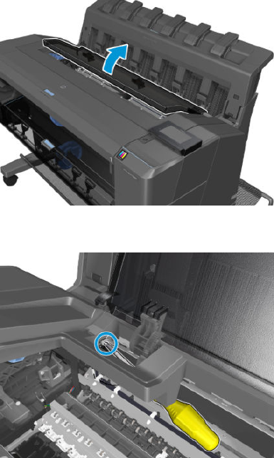
Window Sensor
Removal
1. Open the window.
2. Remove the T-8 screw.
296 Chapter 6 Removal and installation ENWW

3. Unroute and disconnect the cable.
ENWW Window Sensor 297

HP 727 Printhead installation tips and tricks
The new printers come with a whole new set of innovations, such as an output stacker tray, a new printhead, and
new network capabilities. In order to ensure the implications of these new designs and dierent installation
processes are well understood, HP has developed this document to assist in the installation process.
First checks
NOTE: Don’t forget to install the latest rmware!
Over the last few months new rmware versions have been generated improving product stability and adding
new features.
TIP: Download the latest rmware from www.hp.com/go/T1500/software to a USB. When booting the printer
for the rst time, the printer will request to select the Front Panel Language. After the selection and before
installing the inks, plug the USB with the latest Firmware to upgrade the printer.
NOTE: The rmware is the same for all printers.
Also, if the printer has a rmware previous to the release MRYMFP_02_00_02.5 you will be requested to install
this one rst. So it’s useful to have two USBs: one with the newest version and one with the
MRYMFP_02_00_02.5.2.
How to install the HP 727 printhead successfully
The HP 727 printhead requires a new installation process.
You can get familiar with it following the instructions on the printer Front Panel when installing it. Also, watch the
video Installing a printhead on the HP Designjet T920, T1500 and T2500 on YouTube http://www.youtube.com/
watch?v=XaqEA81qgAw.
Make sure tube connectors are moistened:
1.
298 Chapter 6 Removal and installation ENWW
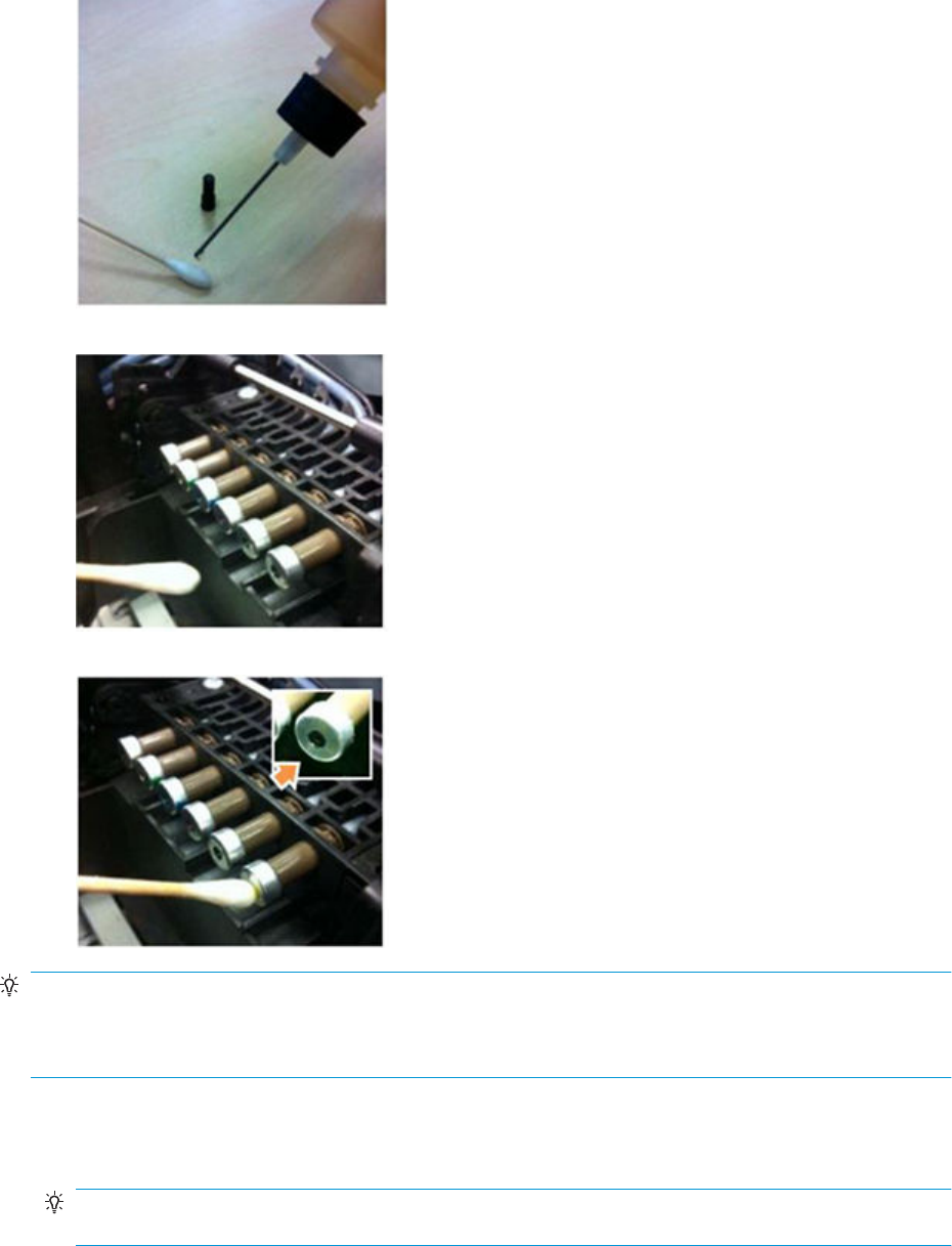
2.
3.
4.
TIP: If the carriage latch is particularly sti or hard to close, or if the blue latch is not staying completely at
with the printhead inserted, please moisten the tube connectors with a Q-Tip/cotton bud that is wet with water
or PEG (Polyethylene glycol) as shown above. After doing it, re-insert the printhead and check again that the blue
latch is completely at.
While closing the printhead, pay special attention to the following steps:
1. The Carriage
TIP: In order to close the carriage, the blue lever must fully engage with the metal bar before you push it
down.
ENWW HP 727 Printhead installation tips and tricks 299
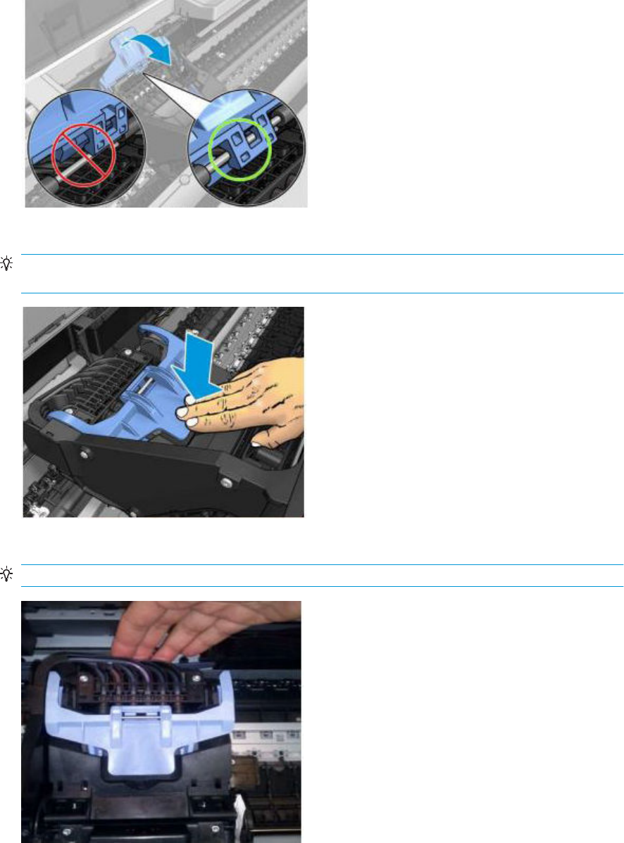
2. The Latch
TIP: Once closed down the latch should remain at over the printhead. This ensures that the Printhead is
properly inserted in the tubes.
3. The Rear
TIP: Once closed, you can still push against the rear side of the carriage to ensure it is properly closed.
300 Chapter 6 Removal and installation ENWW
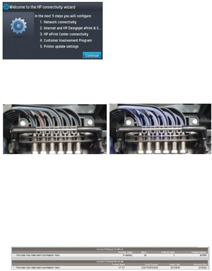
After the installation don’t forget to…
●Before nishing installing the printer, it’s recommended to enable the Automatic Firmware Upgrade in
order to help customers to have the printer up-to-date easily. Follow the steps provided at Connectivity
►Connectivity Wizard.
●Check that the ink tubes are completely lled. This can be done by launching a printhead replacement. This
will move the carriage to the center of the printer and allow visual access. Once the tubes are visually
veried, the printhead replacement can be canceled.
Filled tubes are darker, and yellow tube looks reddish: Empty tubes have a bluish shade:
Resolving issues
When having any problem you can contact HP Service for further assistance. To get the most eective help, the
following information can be helpful:
●When did you have the problem? Was there a printhead message before lling the tubes or after?
●When there is a printhead reseat/replace message, are all the tubes lled or only some? Which ones?
●What is the printhead Error Code?
–This information is available at the Embedded Web Server: Support ►Service support ►Printer
information. This will open a new page. Select the All pages tab. Download this page or print it to a
PDF le.
If you happen to have an issue during the Printhead & Ink initialization, you will need to cancel the
process in order to get straight to the network setup.
ENWW HP 727 Printhead installation tips and tricks 301

At the end of the network setup you will be able to access the Embedded Web Server by typing the
printer IP Address in your Web Browser.
What should I do if the printhead is rejected?
1. The printhead is rejected before lling the tubes.
If the printer persistently gives a Printhead Reseat message before lling the tubes with ink, the most
common solution is to replace the printhead for a new one. HP Limited Warranty covers the printhead for a
period of 1 year from date of installation or 4000 ml of HP ink have been cycled through it, whichever
occurs rst.
2. The printhead is rejected after lling the tubes and tubes:
a. In order to discard any Hardware issue, it is recommended to run the diagnostics for Service Station
►Primer and Ink Delivery System diagnostics available in the Service Menu.
b. Once any Hardware issue is discarded, the most common solution is to launch a new Tubes Purge
again with new set of ink and a new printhead.
TIP: If any tube or printhead channel is still empty, remove all the cartridges before doing any troubleshooting.
Otherwise, the empty tube can mislead the printer and cause to detect it as faulty or empty. Contact HP and a
Service Engineer will lead you through testing the printer subsystems and conrm that only a new tube purge is
required.
HP is committed to improve the installation experience of these products and has:
●Evaluated printhead shipping methods, developing a new packaging strategy both for printhead and
printer.
●Created new rmware versions to address common installation problems.
●Developed a video and this ‘tips and tricks’ document to clarify the installation steps, highlighting
dierences versus previous products.
302 Chapter 6 Removal and installation ENWW
Ink Service kit
As of March 2014 the service kit CR357-67088 Ink Kit is available.
The kit includes a set of 69cc ink cartridges for all HP 727 inks: matte black, gray, photo black, cyan, magenta,
and yellow.
The kit should be used when troubleshooting printhead issues, as it allows the following:
●Install a new printhead.
●Run a tube purge.
ENWW Ink Service kit 303

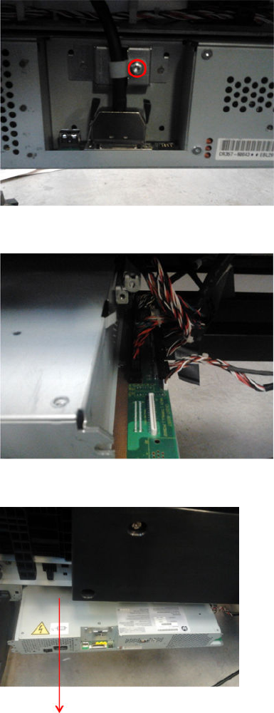
4. Remove the front panel cable and the T-10 screw. For the T2500 and T3500, you will also need to
disconnect the USB cable.
5. Move forwards 15 cm and then disconnect the cables.
6. Remove the E-Box from the printer.
ENWW Open the E-Box 305
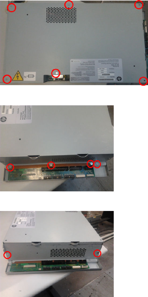
7. Remove six T-8 screws.
8. Remove four T-8 screws.
9. Remove two T-8 screws.
306 Chapter 6 Removal and installation ENWW
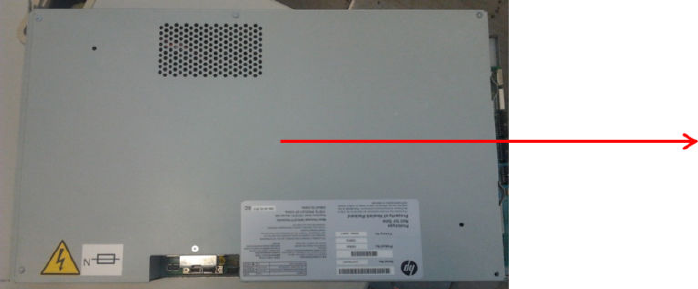
10. Slide out the E-Box cover.
ENWW Open the E-Box 307
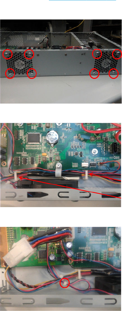
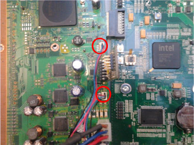
5. Disconnect the cables.
6. Remove the E-Box fans.
ENWW E-Box fan 309
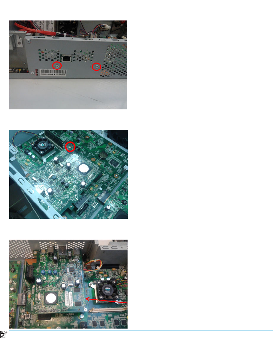
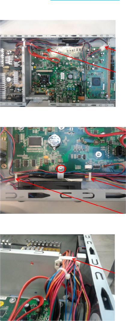
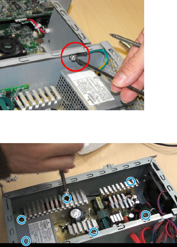
5. Remove grounding cable T-25 screw.
6. Remove the power supply unit.
312 Chapter 6 Removal and installation ENWW
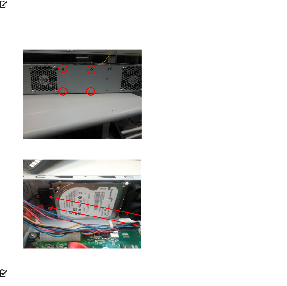
Hard disk drive
Removal
NOTE: If you try to insert a previously used hard disk drive, the product displays a System Error, and will not
start successfully.
1. Open the E-Box. See Open the E-Box on page 304.
2. Remove 4 PH1 screws.
3. Disconnect the cable.
4. Remove the hard disk drive.
NOTE: Remember that after installing a new Hard Disk Drive all previous custom paper presets and printer
applications may need to be reinstalled.
ENWW Hard disk drive 313
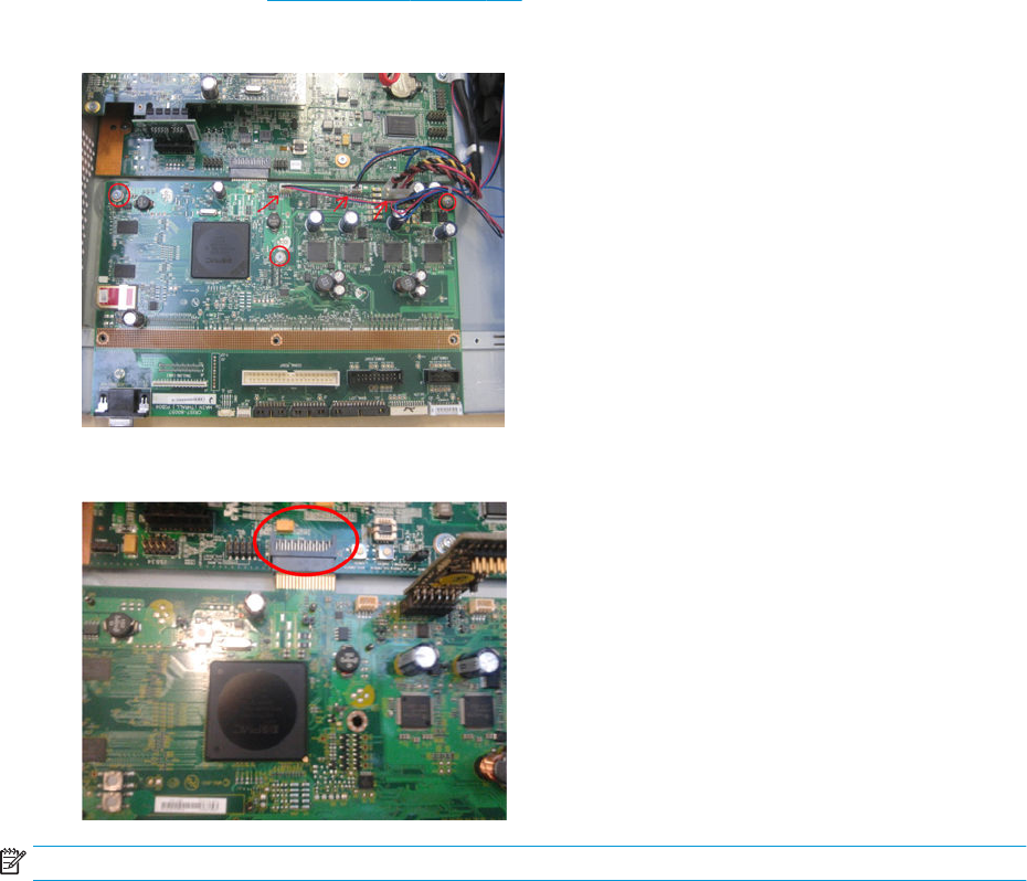
Engine PCA
Removal
1. Open the E-Box. See Open the E-Box on page 304.
2. Disconnect cables and remove three T-8 screws.
3. Slide out and remove the engine PCA (which is connected to the formatter PCA).
NOTE: The red PCA, Cryptoasic sim, must be installed in the new engine PCA.
314 Chapter 6 Removal and installation ENWW
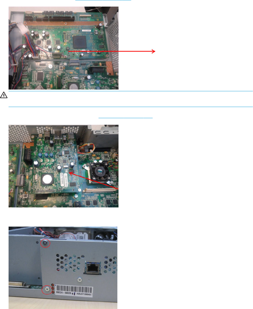
Formatter PCA
Removal
1. Use the power switch at the rear to turn o the printer, then disconnect the power cord.
2. Remove the engine PCA. See Engine PCA on page 314.
WARNING! If the engine PCA is not removed before the formatter, the bridge connections may be
damaged.
3. Remove the Jester and Riser PCAs. See Jester PCA on page 310.
4. Remove the two screws shown.
ENWW Formatter PCA 315

5. Disconnect the cables and remove the clamp.
6. Remove four T-8 screws and the L-shaped metal sheet.
316 Chapter 6 Removal and installation ENWW
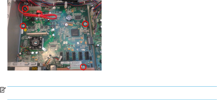
7. Remove four T-8 screws.
8. Remove the formatter PCA.
NOTE: For T920, T1500, T2500 revB SKU, and T3500 all SKUs (A and B), remember to replace the
formatter together with the Hard Disk Drive.
ENWW Formatter PCA 317
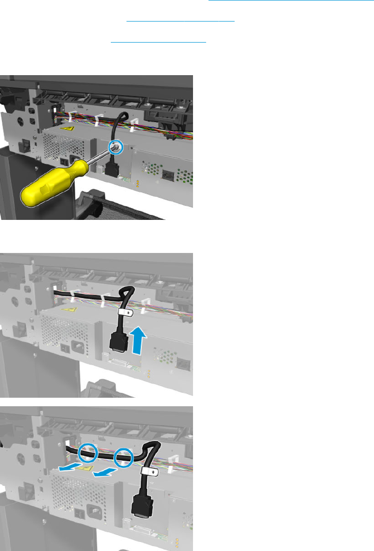
Front panel
Removal
1. Remove the main cover on the front panel side. See Main cover (front panel side) on page 281.
2. Remove the output platen. See Output platen on page 290.
3. Remove the rear cover. See Rear cover on page 295.
4. Remove the T-20 screw from the clamp.
5. Disconnect and unclip the front panel cable.
318 Chapter 6 Removal and installation ENWW
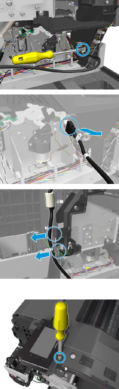
6. Remove the screw, pull the cable through the hole, and unclip it.
7. Remove the front panel screw.
ENWW Front panel 319
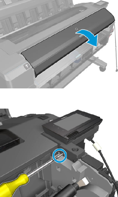
8. Open the top roll cover.
9. Remove the hidden screw.
320 Chapter 6 Removal and installation ENWW
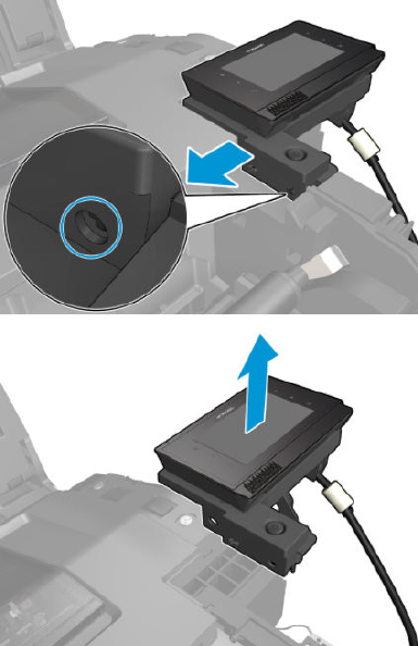
10. Remove the front panel.
ENWW Front panel 321
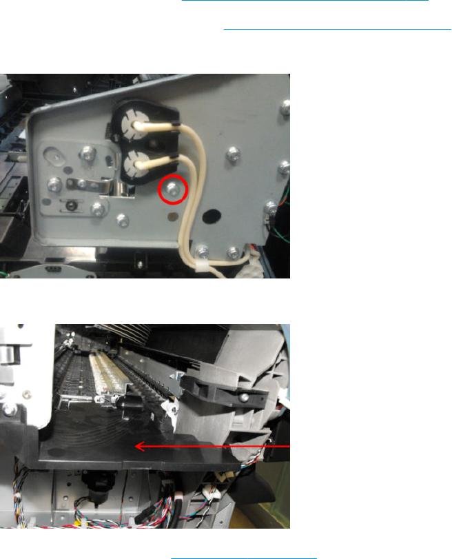
Carriage
Removal
1. Remove the top cover and Window.
2. Remove the SVS main cover. See Main cover (service station side) on page 283.
3. Remove the Front Panel main cover. See Main cover (front panel side) on page 281.
4. Loosen the T-20 screw belt tensioner.
5. Remove the starwheel lifter cover and actuator.
6. Remove the encoder strip. See Encoder Strip on page 333.
322 Chapter 6 Removal and installation ENWW
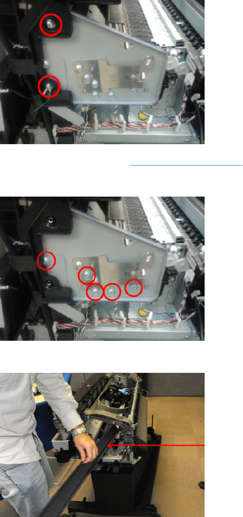
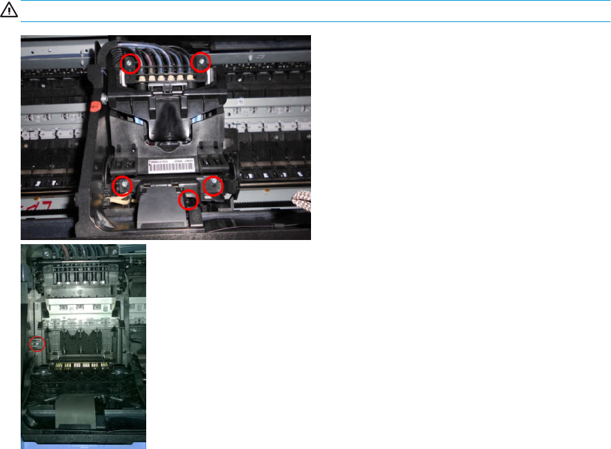
11. Remove 6 screws and the printheads.
WARNING! When unplugging the trailing cable, be careful not to damage the corners of the cable end.
324 Chapter 6 Removal and installation ENWW
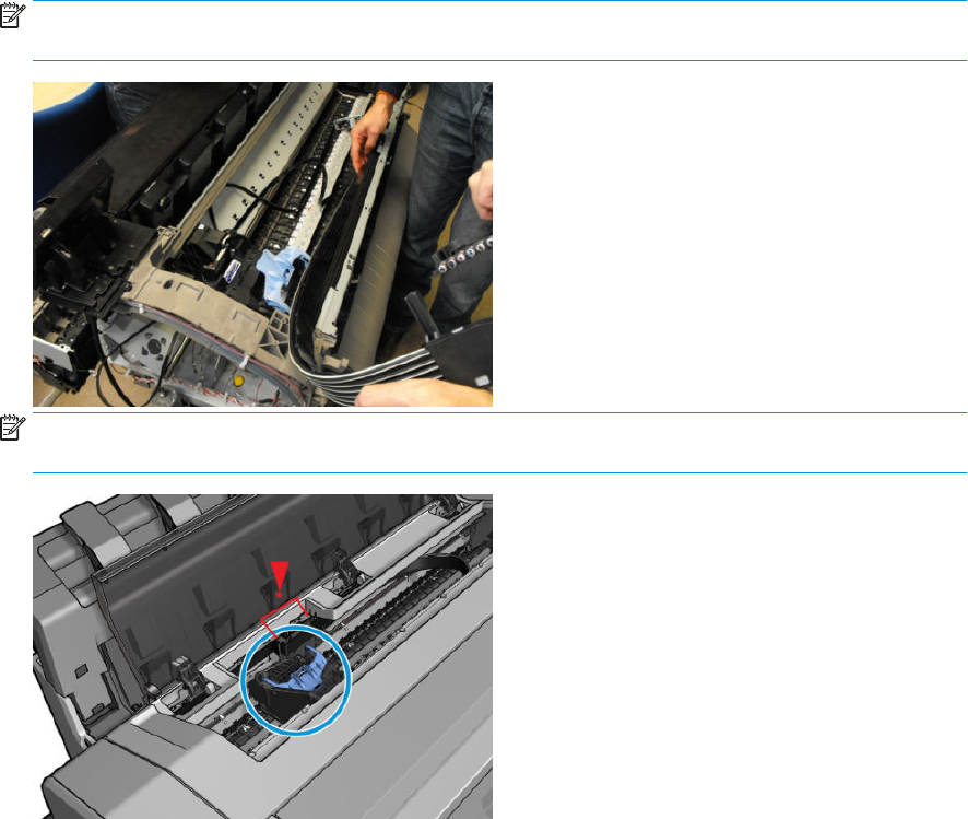
12. Remove the carriage.
To install de carriage, put the tubes into position rst.
NOTE: When installing the crane, check that the needles support is properly attached with the levers on
the sides. The levers help to move the needles down inside the printhead when the carriage latch is closed.
NOTE: After installing the carriage, when closing the latch, make sure the carriage is placed in the
printhead replacement position so the carriage doesn't interfere with the rear guide.
ENWW Carriage 325
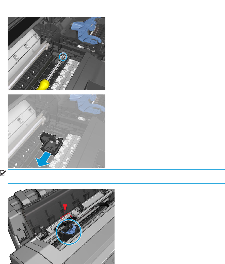
Line Sensor
Removal
1. Open the window.
2. Move the carriage to create a good position for manipulating the carriage.
3. Remove the carriage PCA. See Carriage PCA on page 327.
4. Remove the screw and the Line Sensor.
NOTE: After installing the carriage, when closing the latch, make sure the carriage is placed in the
printhead replacement position so the carriage doesn't interfere with the rear guide.
326 Chapter 6 Removal and installation ENWW
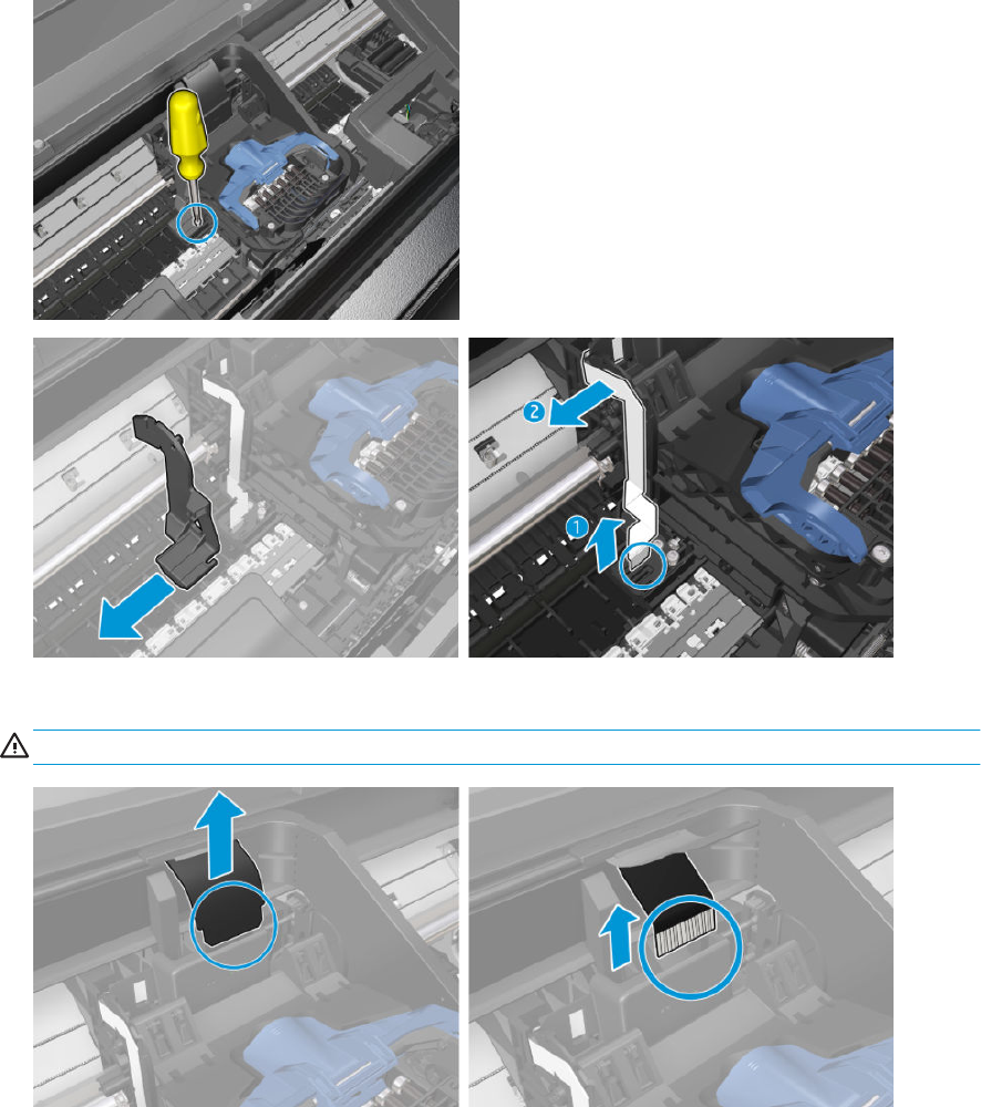
Carriage PCA
Removal
1. Open the window and initiate printhead replacement in order to move the carriage to the middle of the
printer.
2. Remove the T-15 screw and disconnect the Line Sensor cable.
3. Unclip the mylar, and disconnect trailing cable.
WARNING! When unplugging the trailing cable, be careful not to damage the corners of the cable end.
ENWW Carriage PCA 327
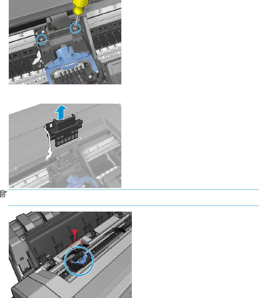
4. Remove the 2 T–15 screws.
5. Remove the carriage PCA.
NOTE: After installing the carriage, when closing the latch, make sure the carriage is placed in the
printhead replacement position so the carriage doesn't interfere with the rear guide.
328 Chapter 6 Removal and installation ENWW
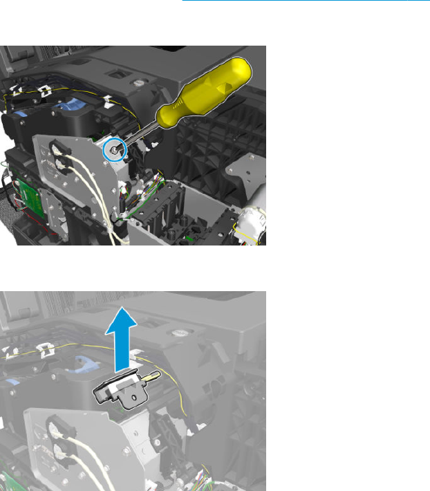
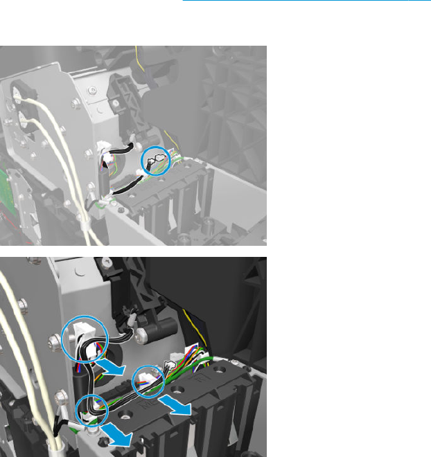
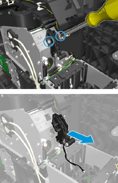
3. Remove the 2 T-20 screws, and the PRS actuator.
ENWW PRS Actuator 331
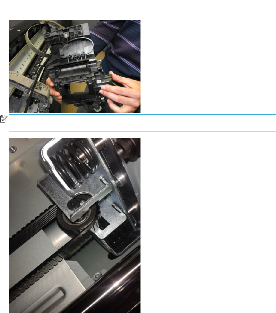
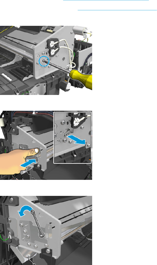
Encoder Strip
Removal
1. Remove the SVS main cover. See Main cover (service station side) on page 283.
2. Remove the Front Panel main cover. See Main cover (front panel side) on page 281.
3. Remove the T-10 screw.
4. Press the bracket to release the encoder strip tension.
5. Remove the 5.5 mm nut.
ENWW Encoder Strip 333
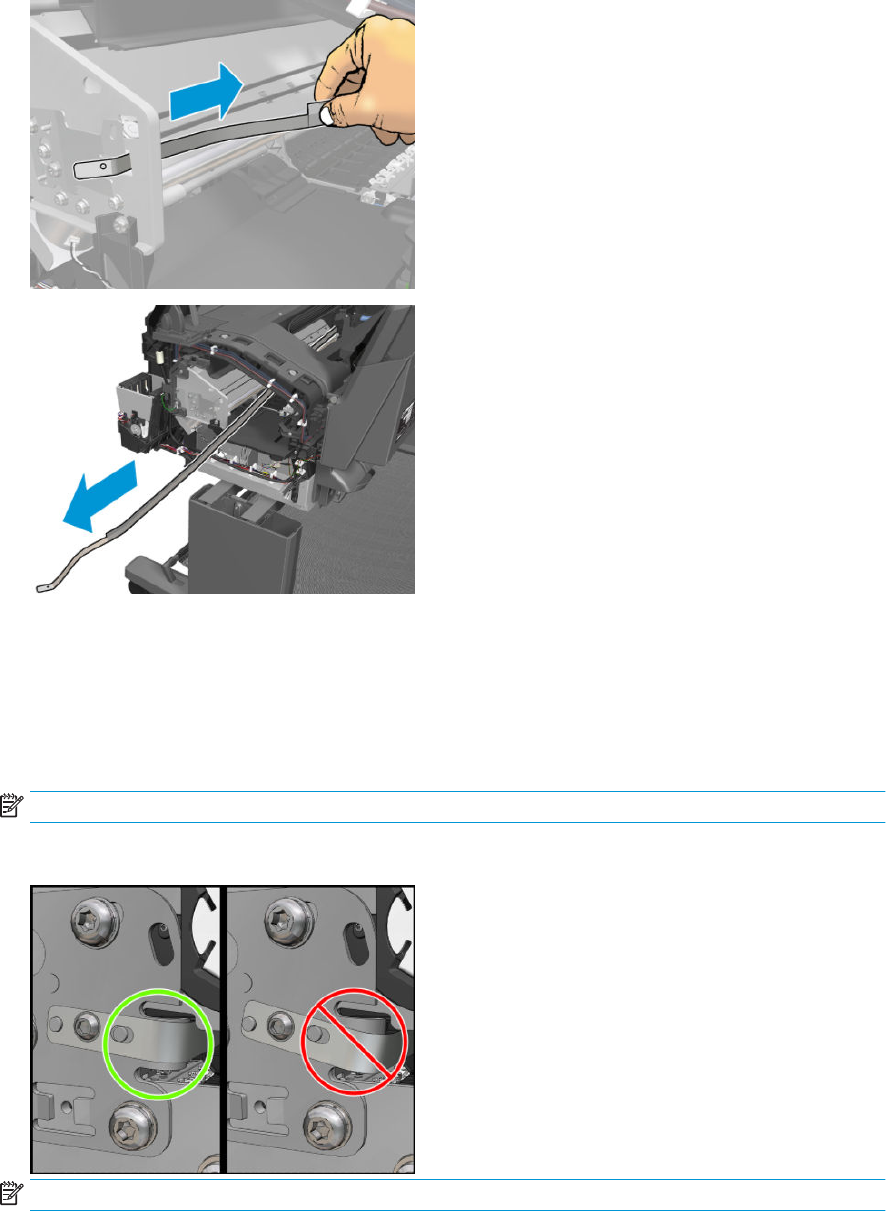
6. Remove the Encoder Strip.
Installation
1. Position the encoder strip.
2. Press the spring to allow the encoder to t into the nut.
3. Tighten the nut manually.
NOTE: Do not tighten with a tool, the force would be too much and the encoder could slide down.
4. Tighten the T10 screw while hand holding the encoder to prevent it from sliding.
NOTE: Run feed and cut.
334 Chapter 6 Removal and installation ENWW
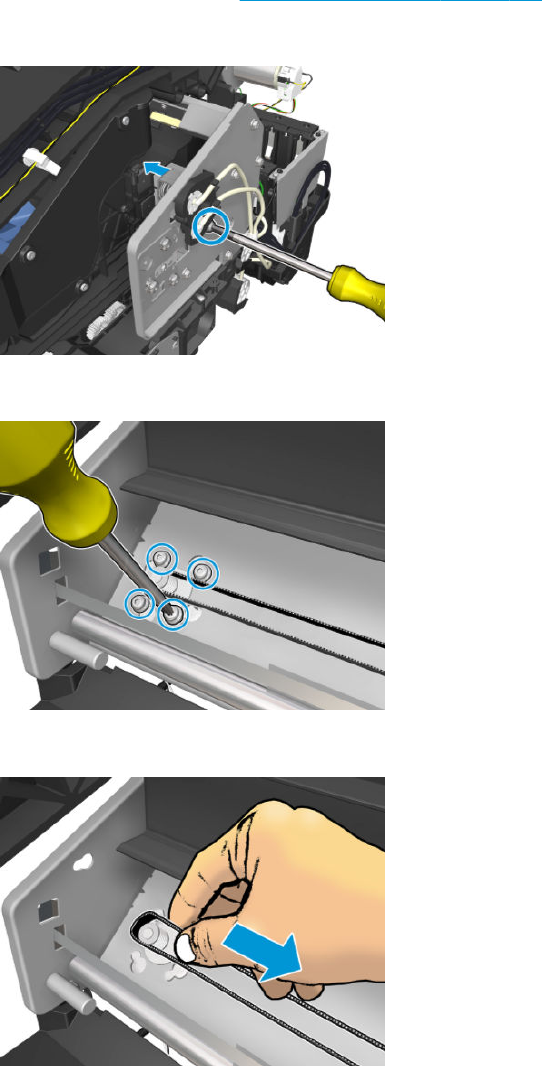
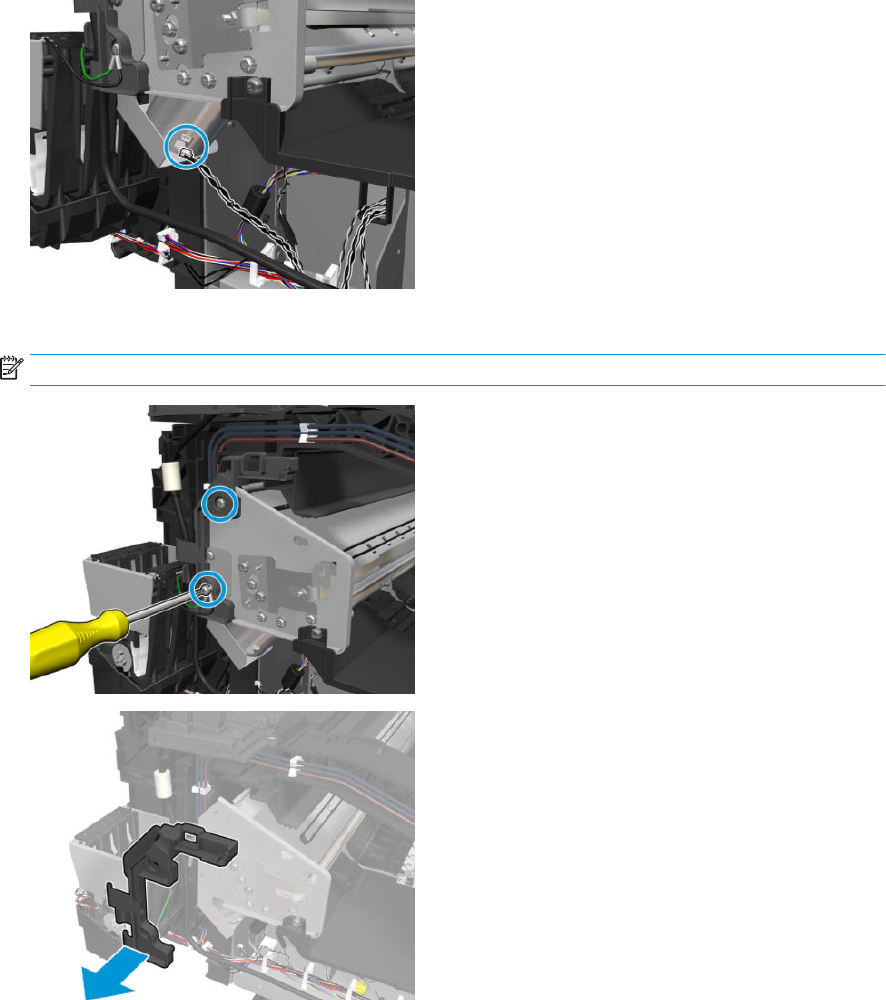
5. Disconnect the cable.
6. Remove the 2 screws in order to remove the piece.
NOTE: Hold the Scan Axis Motor in place when removing the screws.
336 Chapter 6 Removal and installation ENWW
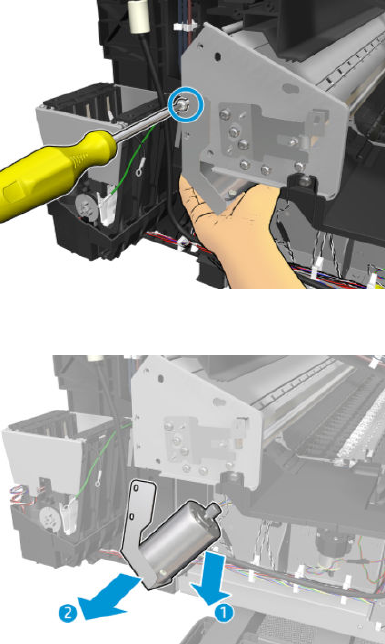
7. Remove the screw in order to remove the metallic piece.
8. Remove the Scan Axis Motor.
ENWW Scan Axis Motor 337
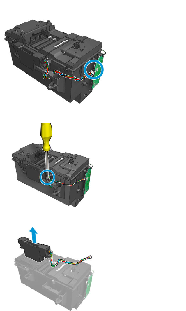

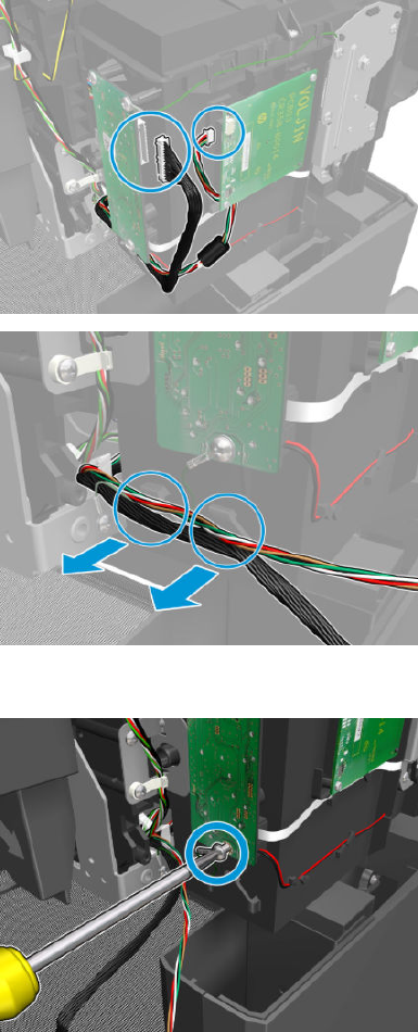
3. Disconnect and unroute the cables.
4. Remove the grounding screw.
340 Chapter 6 Removal and installation ENWW
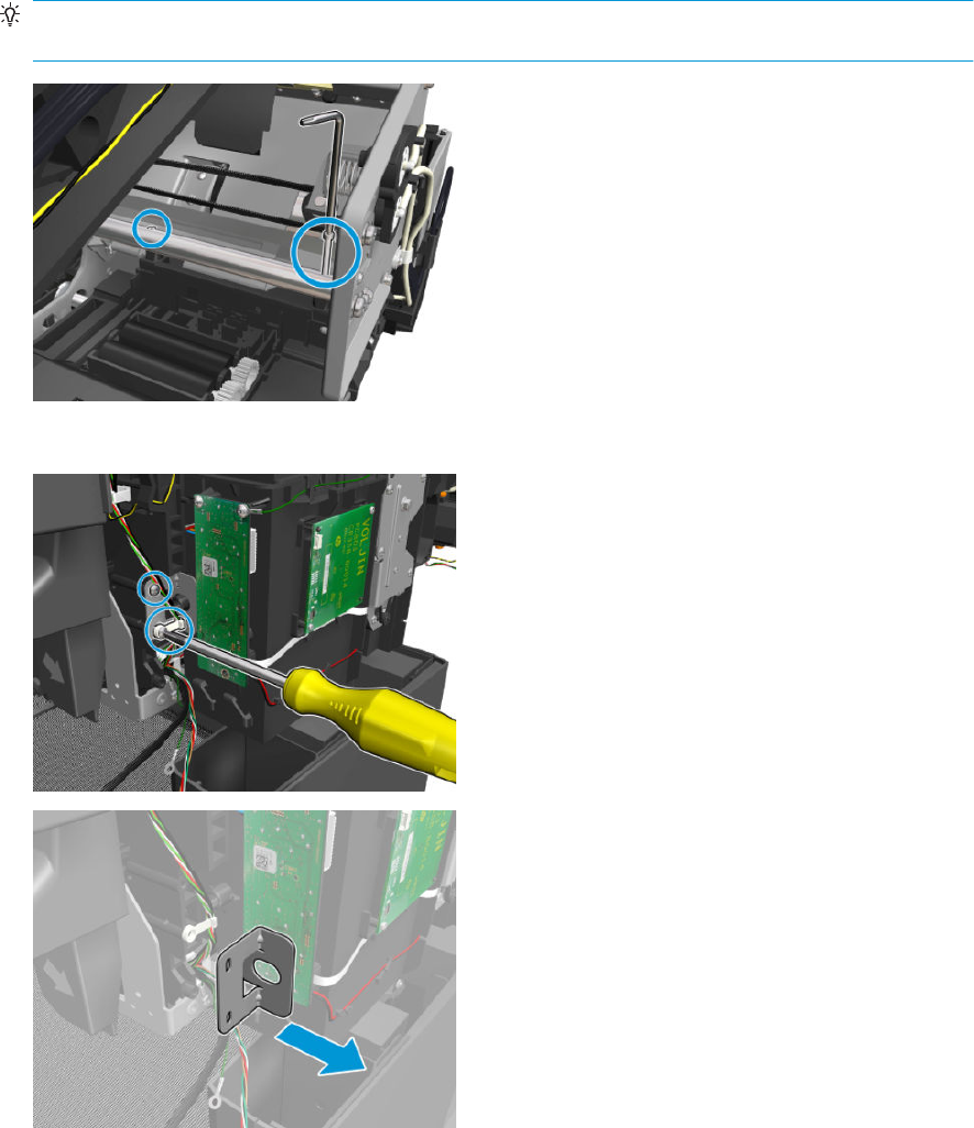
5. Remove the 2 allen screws from the Slider Rod.
TIP: Cover the service station with a A4/E size sheet of paper to prevent it from getting dirty and to
protect against screws falling into the ink container.
6. Remove the 2 T-15 screws and the left bracket.
ENWW Service Station with Drop Detector 341

7. Remove the Service Station.
342 Chapter 6 Removal and installation ENWW
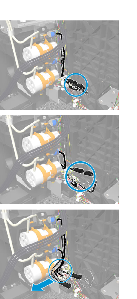
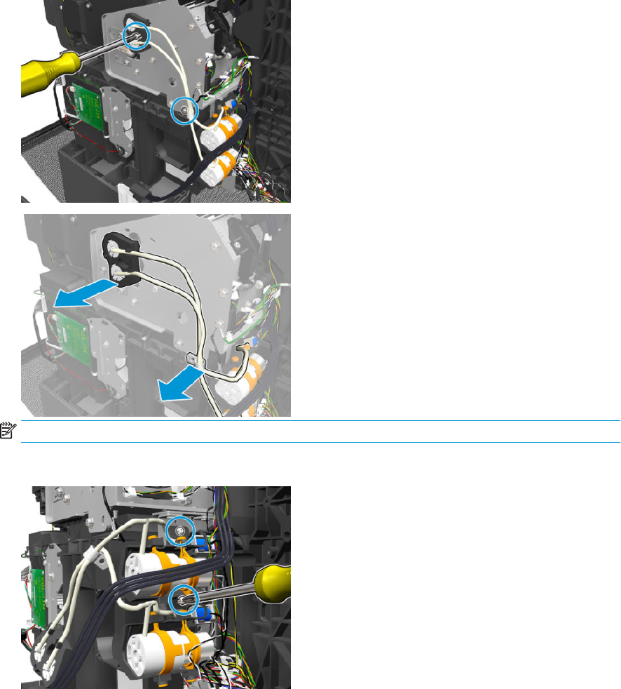
3. Remove the T-20 screw, the T-10 screw, the tubes, and the plastic pieces.
NOTE: On the rst primer tubes holder make sure the holes are aligned with the holes of the carriage.
4. Remove a T-20 screw from each primer.
344 Chapter 6 Removal and installation ENWW
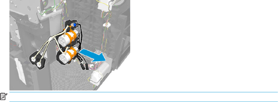
5. Remove the primer.
NOTE: The primer service kit includes the valves, the plastic, and the tubes.
ENWW Primer Assembly 345
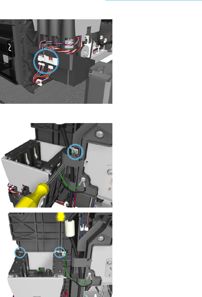
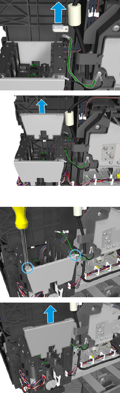
4. Remove the bracket and side plate.
5. Remove 2 screws and the side plate.
ENWW ISS (Ink Supply Station) Front Panel Side 347
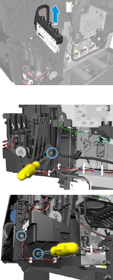
6. Remove the uid inter-connector.
7. Remove 3 T-10 screws.
348 Chapter 6 Removal and installation ENWW

8. Remove the ISS Front Panel Side.
ENWW ISS (Ink Supply Station) Front Panel Side 349
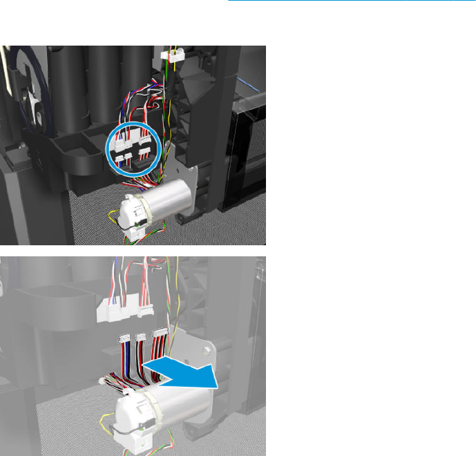
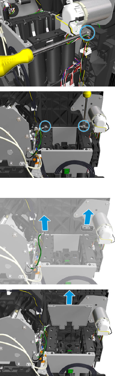
3. Remove 3 T-10 screws.
4. Remove the bracket and side plate.
ENWW ISS SVS Side 351
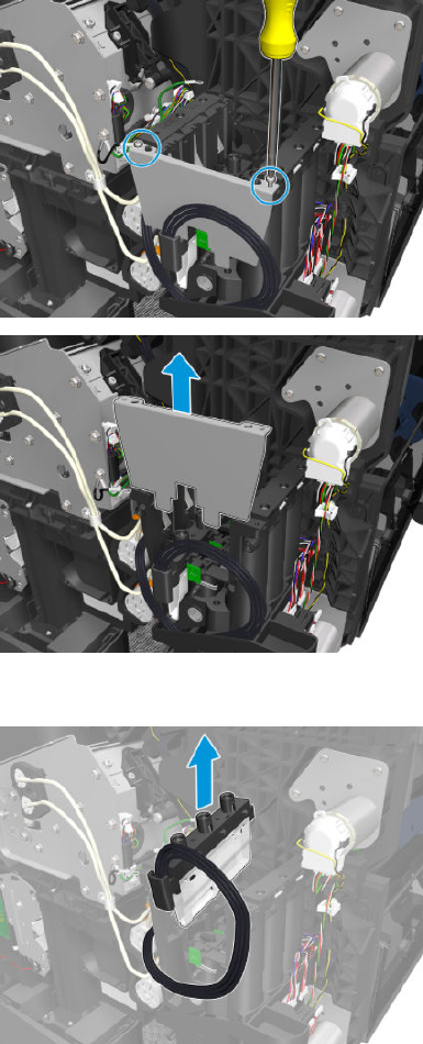
5. Remove 2 screws and the side plate.
6. Remove the uid inter-connector.
352 Chapter 6 Removal and installation ENWW
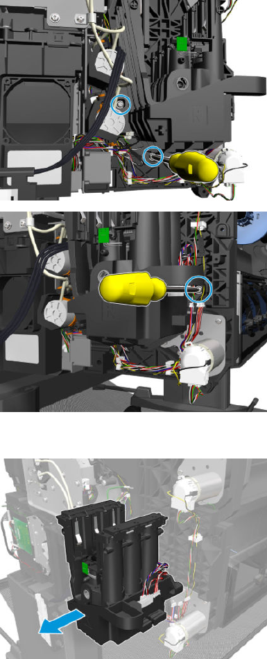
7. Remove 3 T-10 screws.
8. Remove the ISS SVS side.
ENWW ISS SVS Side 353
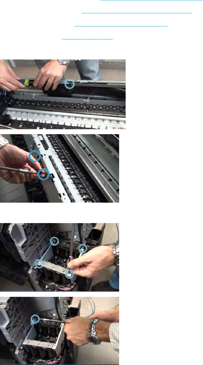
Ink Tubes and Trailing Cable
Removal
1. Remove the Front Panel main cover. See Main cover (front panel side) on page 281.
2. Remove the SVS main cover. See Main cover (service station side) on page 283.
3. Remove the center cover. See Center cover (T920 only) on page 285.
4. Remove the stacker. See Stacker on page 405.
5. Remove the rear beam.
6. Remove the ISSWALL (removing 2 T-10 screws).
354 Chapter 6 Removal and installation ENWW

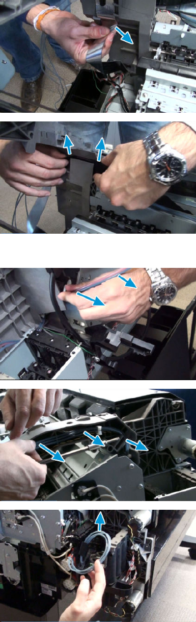
12. Unroute the trailing cable.
13. Unroute the end tubes.
356 Chapter 6 Removal and installation ENWW
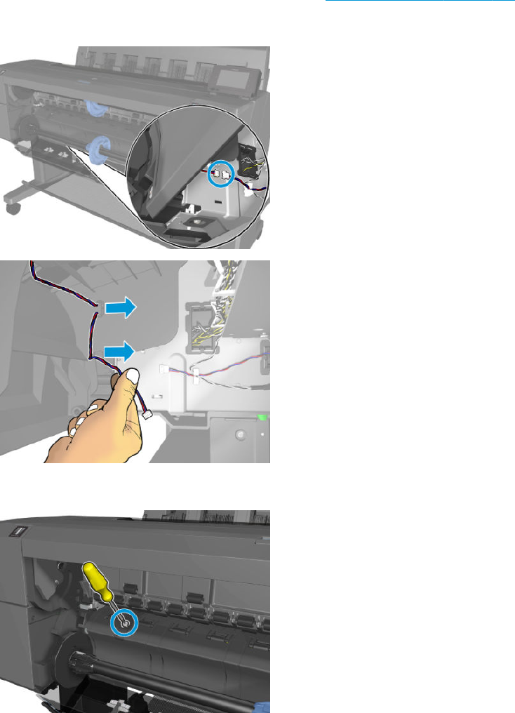
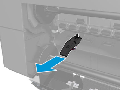
4. Remove the media sensor.
358 Chapter 6 Removal and installation ENWW

Bottom Rewinder Support
Removal
1. Remove the SVS side main cover. See Main cover (service station side) on page 283.
2. Remove the bottom roll cover. See Customer Self Repair Flyers on page 473.
3. Remove the converger. See Converger Assembly on page 287.
4. Disconnect, and unroute the cables.
5. T3500 only: Remove 1 T-15 screw.
ENWW Bottom Rewinder Support 359
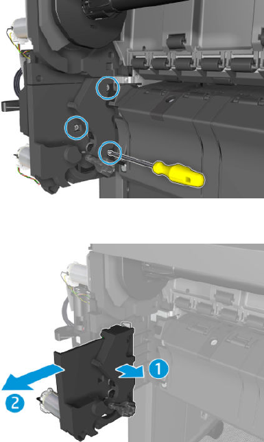
6. Remove 3 T-15 screws and the rewinder.
7. Remove the bottom rewinder support.
360 Chapter 6 Removal and installation ENWW

Top Rewinder Support
Removal
1. Remove the SVS side main cover. See Main cover (service station side) on page 283.
2. Remove the top roll cover. See Customer Self Repair Flyers on page 473.
3. Remove the converger. See Converger Assembly on page 287.
4. Disconnect, and unroute the cable.
5. Remove 3 T-15 screws and the rewinder.
ENWW Top Rewinder Support 361
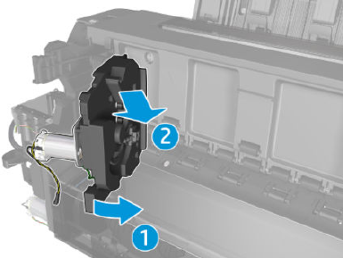
6. Remove the top rewinder support.
362 Chapter 6 Removal and installation ENWW

Top Tip Support
Removal
1. Remove the top roll cover. See Customer Self Repair Flyers on page 473.
2. Remove the converger. See Converger Assembly on page 287.
3. Remove the front panel side cover. See Main cover (front panel side) on page 281.
4. Disconnect, and unroute the cable.
5. Remove 3 T-15 screws.
6. Remove the tip top support.
ENWW Top Tip Support 363
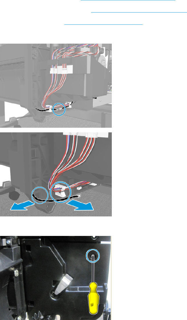
Bottom Tip Support
Removal
1. Remove the bottom roll cover. See Customer Self Repair Flyers on page 473.
2. Remove the front panel side cover. See Main cover (front panel side) on page 281.
3. Remove the converger. See Converger Assembly on page 287.
4. Disconnect, and unroute the cable.
5. T3500 only: Remove 1 T-15 screw.
364 Chapter 6 Removal and installation ENWW

6. Remove 3 T-15 screws.
7. Remove the bottom tip support.
ENWW Bottom Tip Support 365
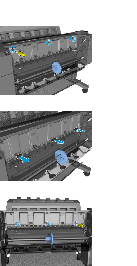
Vertical Media Guide
Removal
1. Remove the top roll cover. See Customer Self Repair Flyers on page 473.
2. Remove the converger. See Converger Assembly on page 287.
3. Remove 3 T-15 cosmetic screws.
4. T920, T1500 and T2500 only: Remove the wheels.
5. Remove the 3 T-15 screws underneath.
366 Chapter 6 Removal and installation ENWW
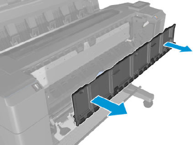
6. Remove the vertical media guide.
ENWW Vertical Media Guide 367
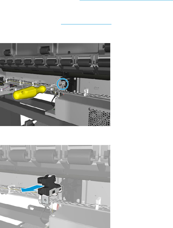
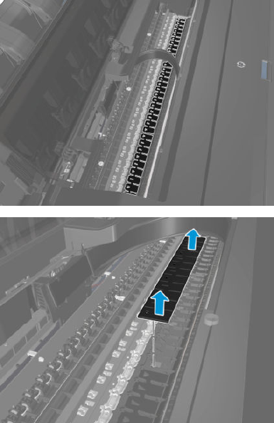
Full Bleed
Removal
1. Open the window.
2. Remove the full bleed foams.
ENWW Full Bleed 369
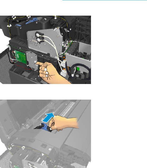
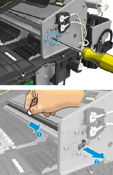
4. Release the Encoder Strip.
ENWW Auto Pinch Lifter 371
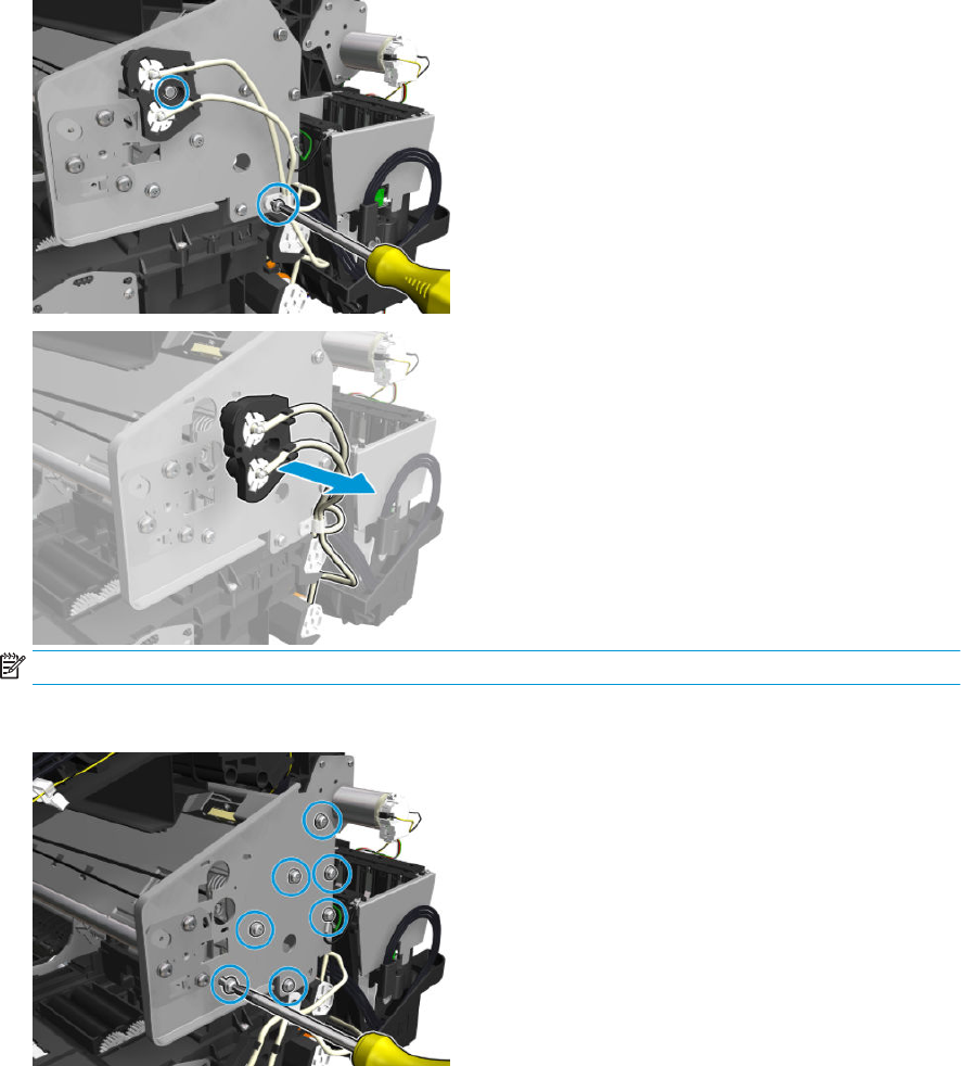
5. Remove 2 screws, and remove the primer tubes.
NOTE: On the rst primer tubes holder make sure the holes are aligned with the holes of the carriage.
6. Remove 7 screws (1 is the tensioner).
372 Chapter 6 Removal and installation ENWW
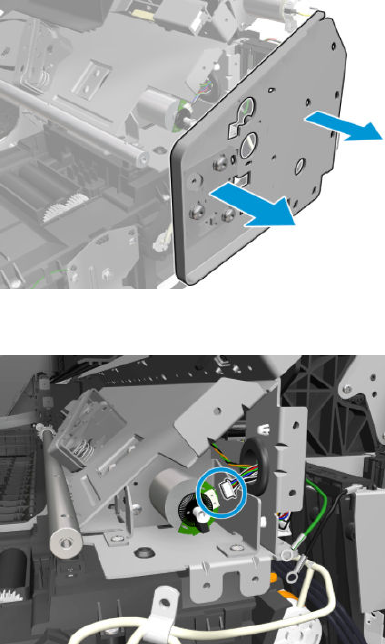
7. Remove the bracket.
8. Disconnect the cable.
ENWW Auto Pinch Lifter 373
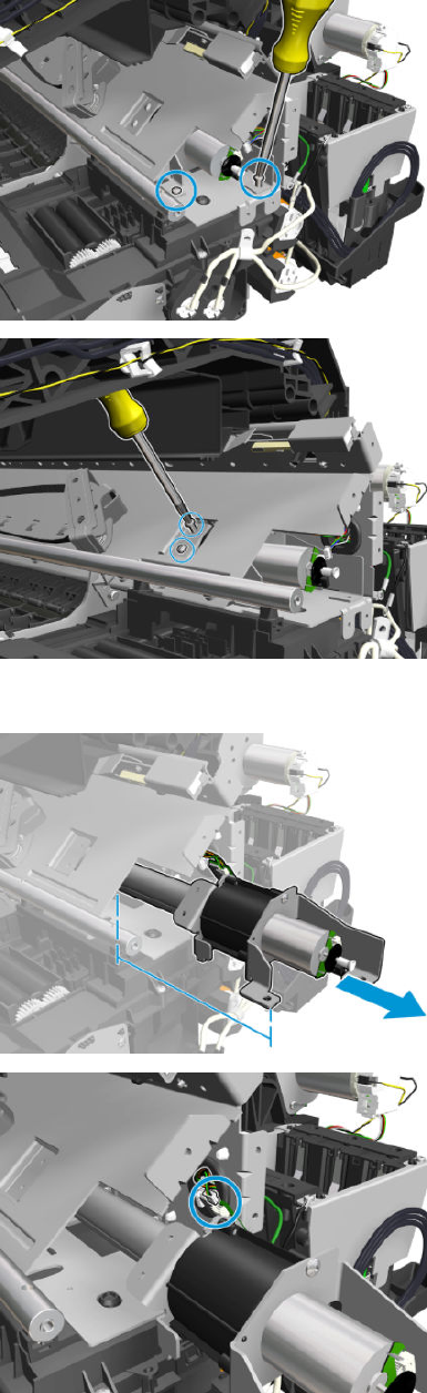
9. Remove 4 screws.
10. Slide out the auto pinch lifter, and disconnect the sensor.
374 Chapter 6 Removal and installation ENWW
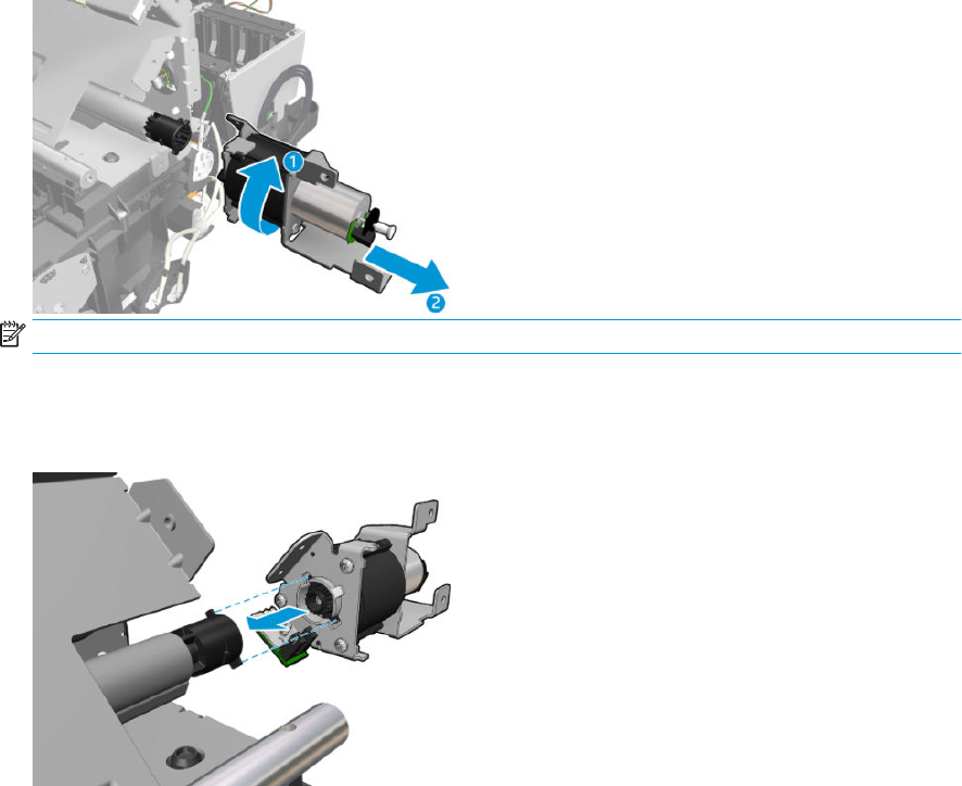
11. Rotate, unlock, and remove the auto pinch lifter.
NOTE: The cam does not need to be removed.
Installation
▲Slide into place and follow the removal procedure in reverse.
ENWW Auto Pinch Lifter 375
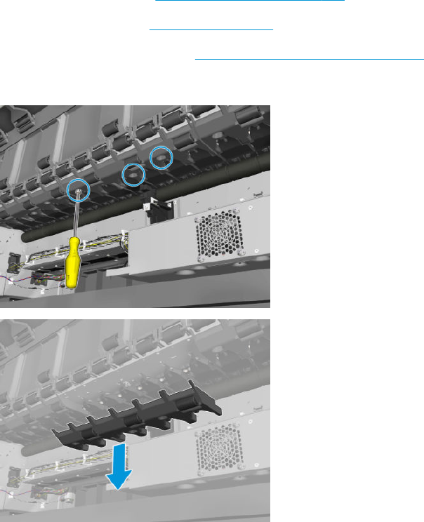
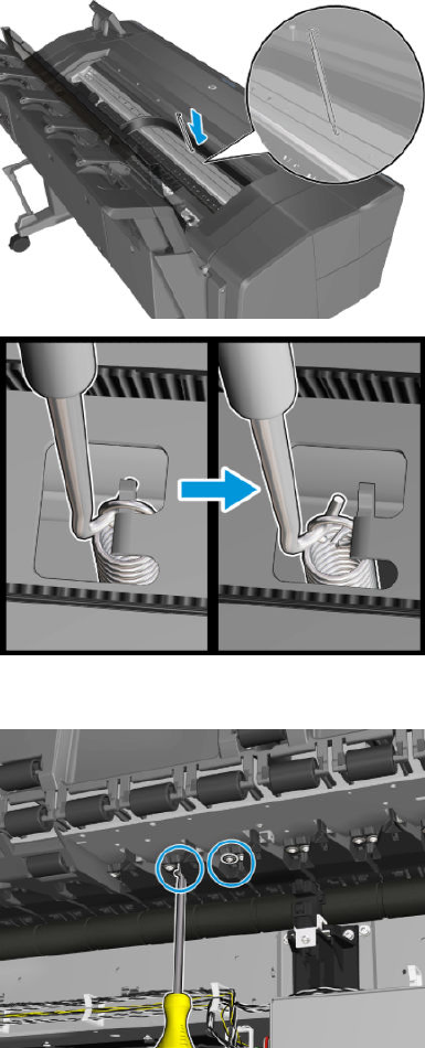
5. Remove the spring using the tool.
6. Remove 2 T-10 screws.
ENWW Pinch Wheel Assembly 377

7. Remove the pinch wheel.
378 Chapter 6 Removal and installation ENWW
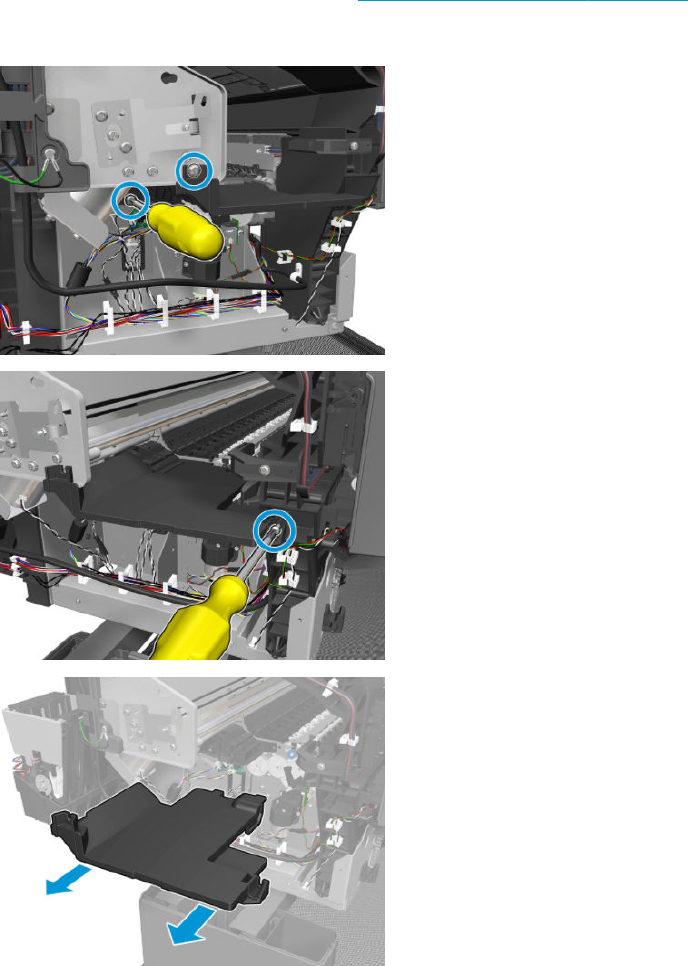
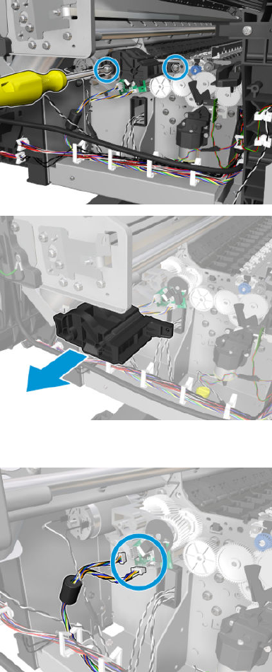
3. Remove the 2 T-7 screws, and then the encoder PCA.
4. Disconnect the cable.
380 Chapter 6 Removal and installation ENWW

5. Remove the 2 screws and remove the connectors.
6. Disconnect the cable, and remove the 3 screws.
ENWW Motor Media Advance Transmission with Encoder 381
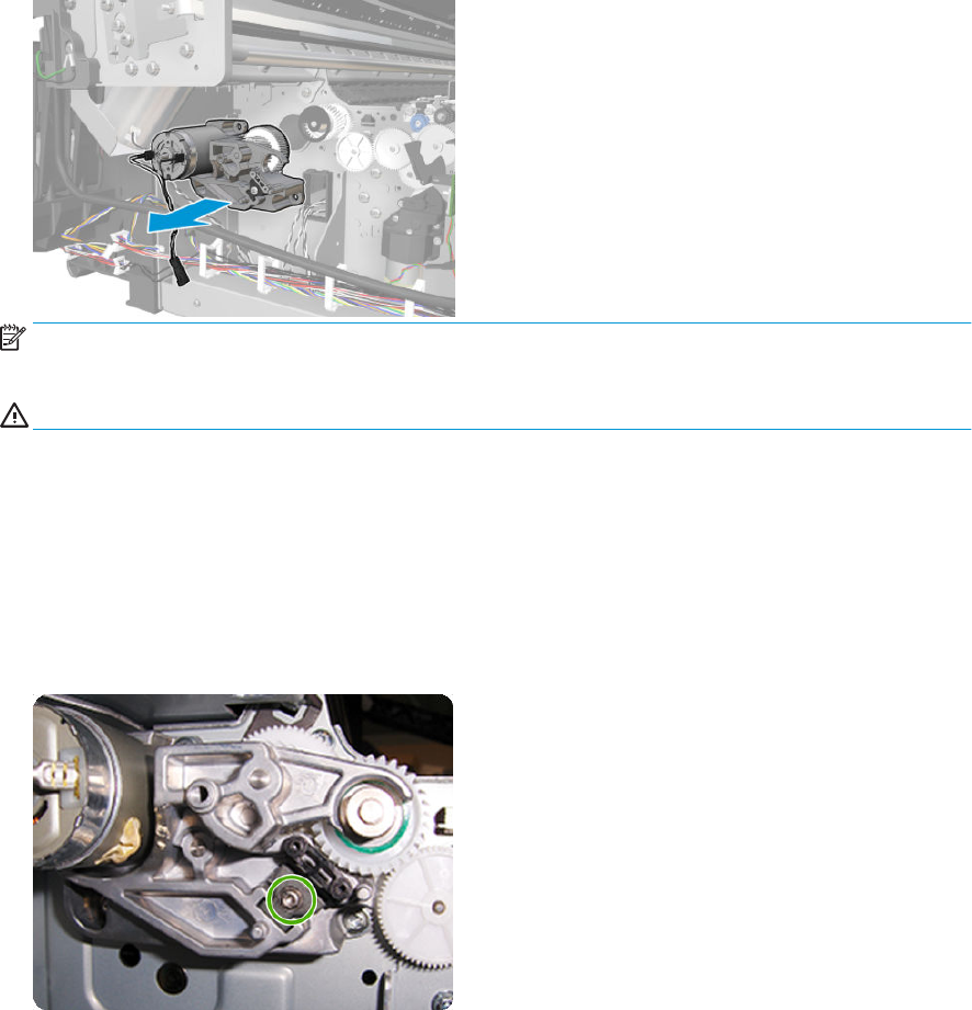
7. Remove the paper axis motor.
NOTE: Never install a used Encoder PCA. This can cause serious problems, and may make the product
unusable.
WARNING! Be careful not to damage the Encoder PCA.
Installation with encoder sensor adjustment
Use the following procedure to install and adjust a new Media Advance Drive. This is the normal procedure that
should be followed in most cases. You will need Media Advance Drive Adjustment Tool from the Tool Kit.
1. Carefully position the Media Advance Drive in the product.
2. Be careful not to touch the encoder sensor adjustment screw; not even when replacing the encoder disc
and sensor.
382 Chapter 6 Removal and installation ENWW
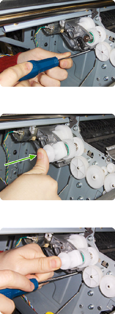
3. Insert the three T-15 attachment screws, but do not fully tighten them.
4. Position the Media Advance Drive Adjustment Tool on the end Media Advance Roller shaft, push it rmly
onto the shaft and maintain a constant pressure to ensure it is ush to the Media Advance Drive.
5. While maintaining pressure on the Media Advance Drive Adjustment Tool, fully tighten the three T-15
attachment screws in the order shown.
6. Remove the Media Advance Drive Adjustment Tool.
Installation with encoder sensor adjustment
Use the following procedure to install and adjust a new Media Advance Drive, and to adjust the encoder sensor.
This procedure is recommended only when the motor mount has to be replaced or the encoder sensor has to be
readjusted. You will need Media Advance Drive Adjustment Tool from the Tool Kit.
1. Carefully position the Media Advance Drive in the product.
ENWW Motor Media Advance Transmission with Encoder 383
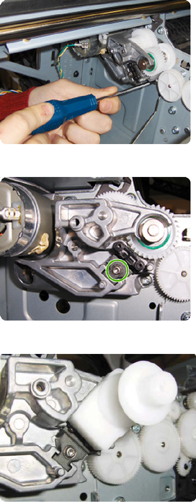
2. Insert the three T-15 attachment screws, but do not fully tighten them.
3. Loosen the encoder sensor adjustment screw.
4. Add the Encoder Sensor Tool to the Media Drive Adjustment Tool.
384 Chapter 6 Removal and installation ENWW
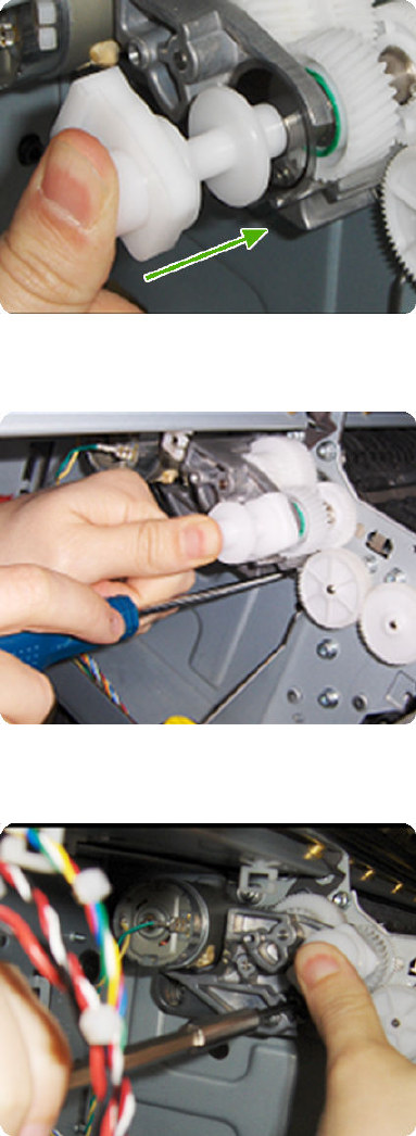
5. Position the Media Advance Drive Adjustment Tool on the end Media Advance Roller shaft, push it rmly
onto the shaft and maintain a constant pressure to ensure it is ush to the Media Advance Drive.
6. While maintaining pressure on the Media Advance Drive Adjustment Tool, fully tighten the three T-15
attachment screws in the order shown.
7. While maintaining pressure on the Media Advance Drive Adjustment Tool, fully tighten the encoder sensor
adjustment screw.
8. Remove the Media Advance Drive Adjustment Tool.
Encoder disk assembly
1. Remove the paper that protects the glue of a new encoder.
ENWW Motor Media Advance Transmission with Encoder 385
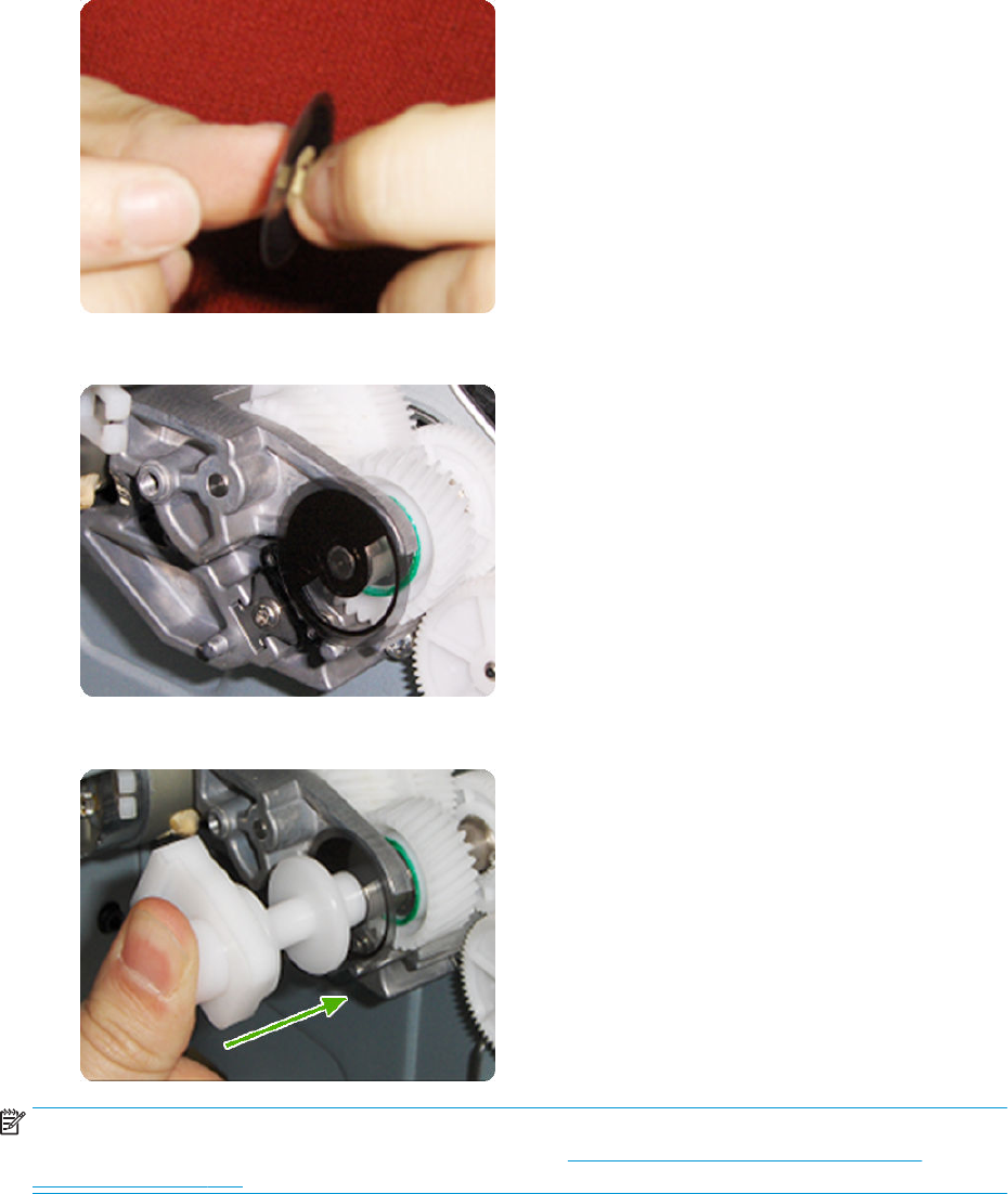
2. Pre-assemble the encoder on the roller without using pressure.
3. Press the encoder using the Media Advance Drive Adjustment Tool (reversed) so that it sticks to the roller.
NOTE: When you nish installing or replacing these components, you must perform the necessary Service
Calibrations. To nd which calibrations you must perform, see Service Calibration Guide to Removal and
Installation on page 278.
386 Chapter 6 Removal and installation ENWW
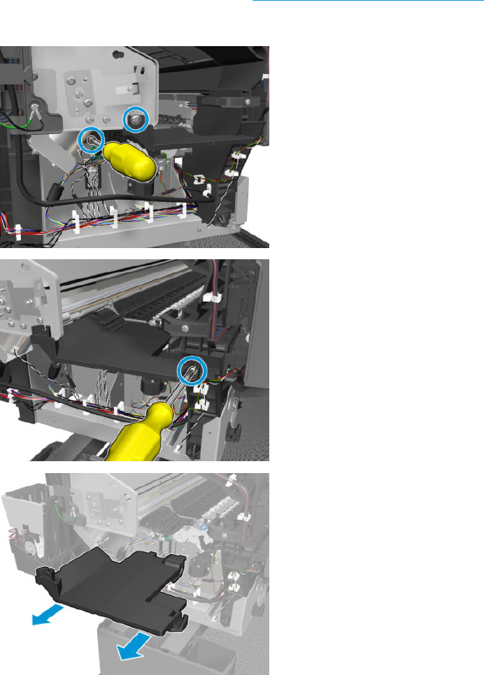
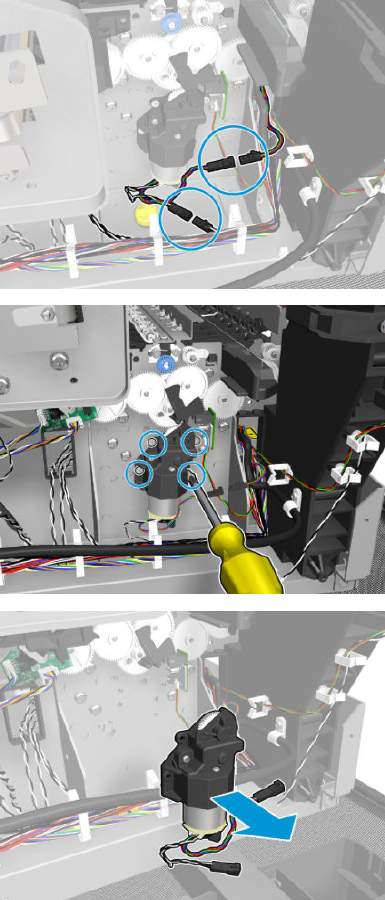
3. Disconnect the cable, remove 4 T-10 screws, and the Starwheel Motor.
388 Chapter 6 Removal and installation ENWW
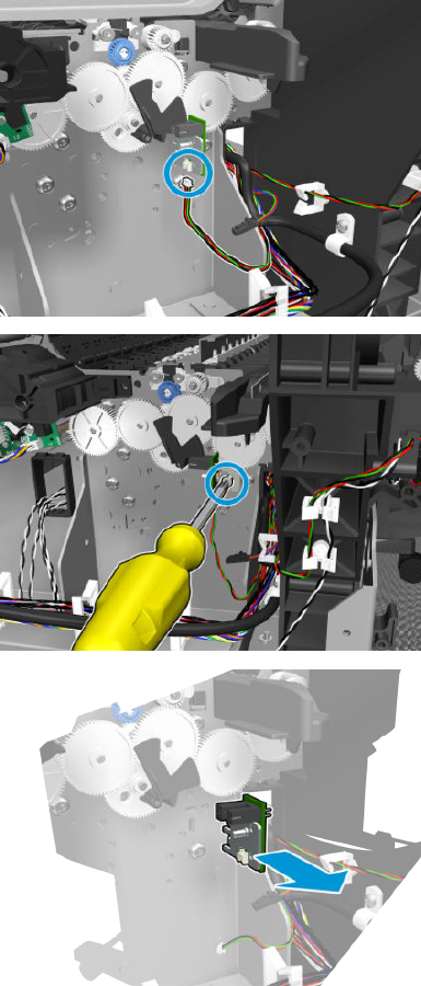
4. Disconnect the cable, remove the screw and the OPTO PCA.
ENWW Starwheel Motor 389
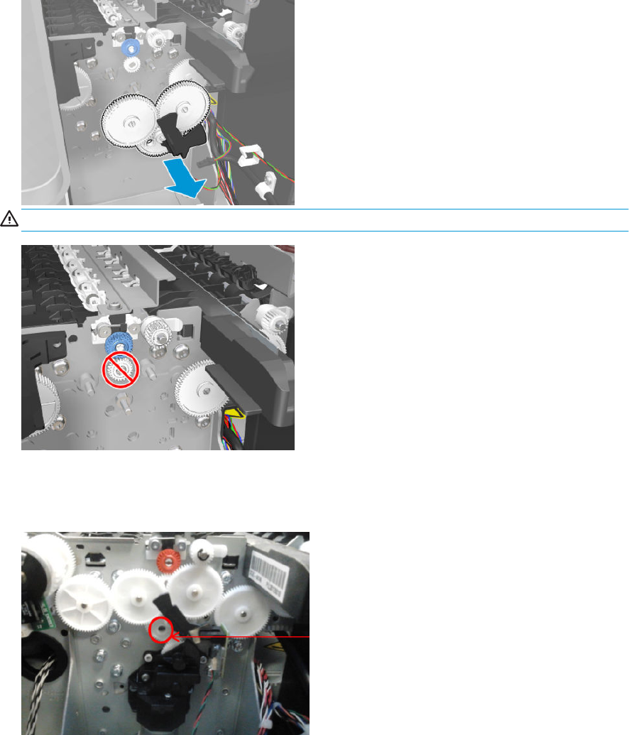
5. Remove the 3 gears.
WARNING! Do not remove the following gear.
Installation
1. To install the gears, they have to t into the hole.
390 Chapter 6 Removal and installation ENWW
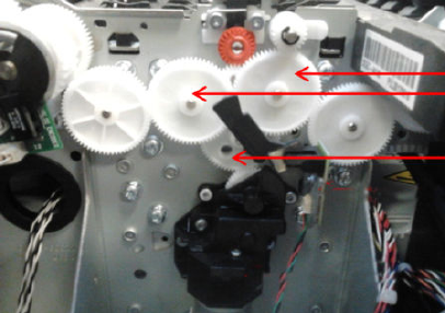
2. Install the new gears that came with the kit reversing the removal process.
ENWW Starwheel Motor 391
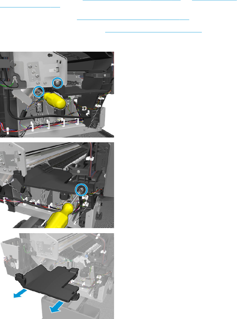
Starwheel Support
Removal
1. Remove the main front covers See Main cover (front panel side) on page 281 and Main cover (service
station side) on page 283.
2. Remove the service station. See Service Station with Drop Detector on page 339.
3. Remove the metal starwheel assembly. See Customer Self Repair Flyers on page 473.
4. Remove the 3T-10 screws, and the starwheel lifter cover.
392 Chapter 6 Removal and installation ENWW

5. Remove 2 screws
6. Remove the plunger.
NOTE: This assembly is on both sides.
ENWW Starwheel Support 393
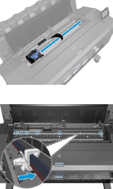
Second Starwheel Rail
Removal
1. Open the window.
2. Move the carriage to the front panel side.
3. Detach and unroute the ink tubes.
394 Chapter 6 Removal and installation ENWW
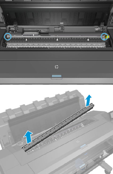
4. Remove 2 T-20 screws, and the second starwheel rail.
ENWW Second Starwheel Rail 395
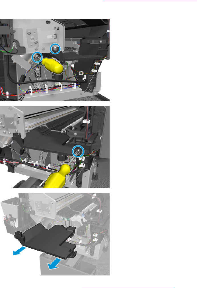
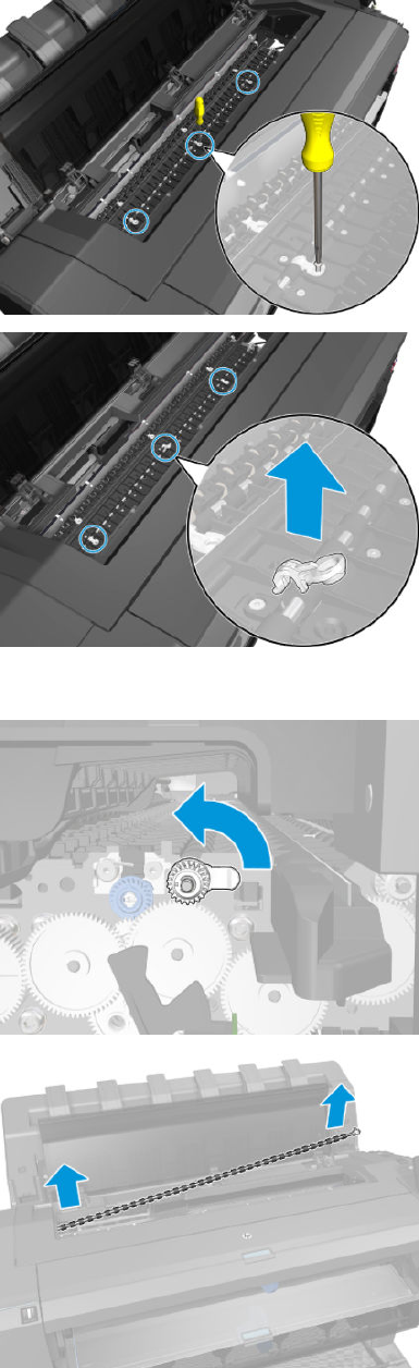
4. Remove the holders.
5. Lift up the ap at both sides and remove the overdrive.
ENWW Overdrive 397

Cutter Platten
Removal
1. Remove the starwheel rail. See Customer Self Repair Flyers on page 473.
2. Remove the overdrive. See Overdrive on page 396.
3. Remove the output platen. See Output platen on page 290.
4. Remove the stacker. See Stacker on page 405.
5. Remove the 2nd starwheel rail. See Second Starwheel Rail on page 394.
6. Remove the 3 holders from the 2nd overdrive.
7. Move the aps from the 2nd overdrive.
398 Chapter 6 Removal and installation ENWW

8. Remove the 2nd overdrive.
9. Remove 13 T-10 screws.
10. Remove 4 T-10 screws.
ENWW Cutter Platten 399
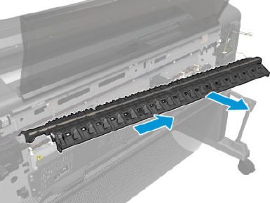
11. Remove the platten.
400 Chapter 6 Removal and installation ENWW
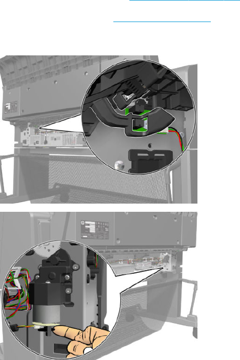
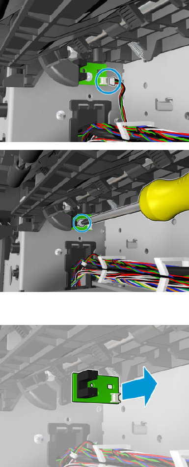
4. Disconnect the cable, and remove the T-10 screw.
5. Remove the sensor valves.
Installation
▲When reinstalling the sensor valves, move the valves into the down position with the motor encoder in
order to check sensor positioning.
402 Chapter 6 Removal and installation ENWW
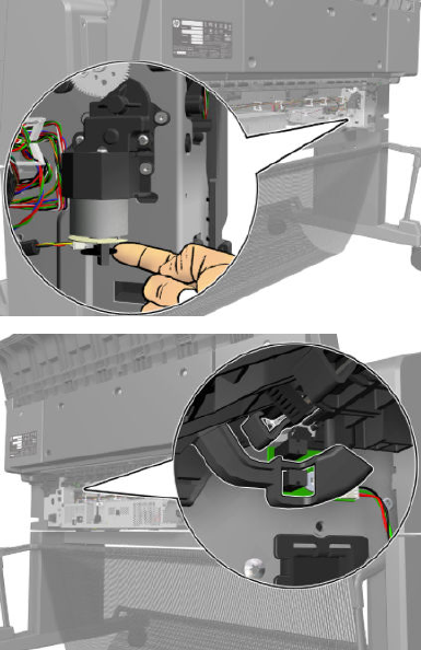
ENWW Sensor Valves 403

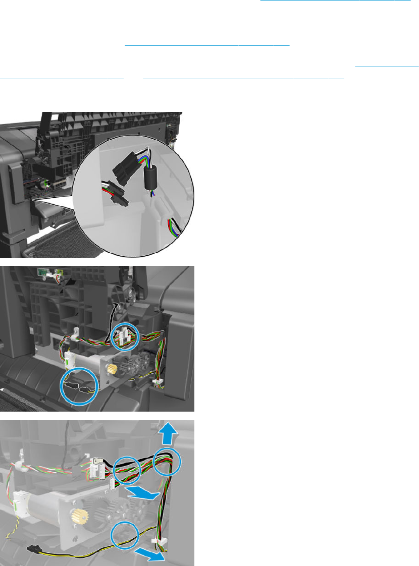
Stacker
T2500 only: adaption kit CR359-67006 must be installed before installing the stacker. This kit is sometimes
referred to as the Stacker MFP SV, or the Stacker adaptor for MFP. See Stacker adaptor for MFP on page 407.
Removal
1. Remove the stacker arms. See Customer Self Repair Flyers on page 473.
2. Remove xed tray cover from the front panel side and from the service station side. See Fixed tray cover
(Front Panel side) on page 291 and Fixed tray cover (service station side) on page 292.
3. Disconnect the cables.
ENWW Stacker 405
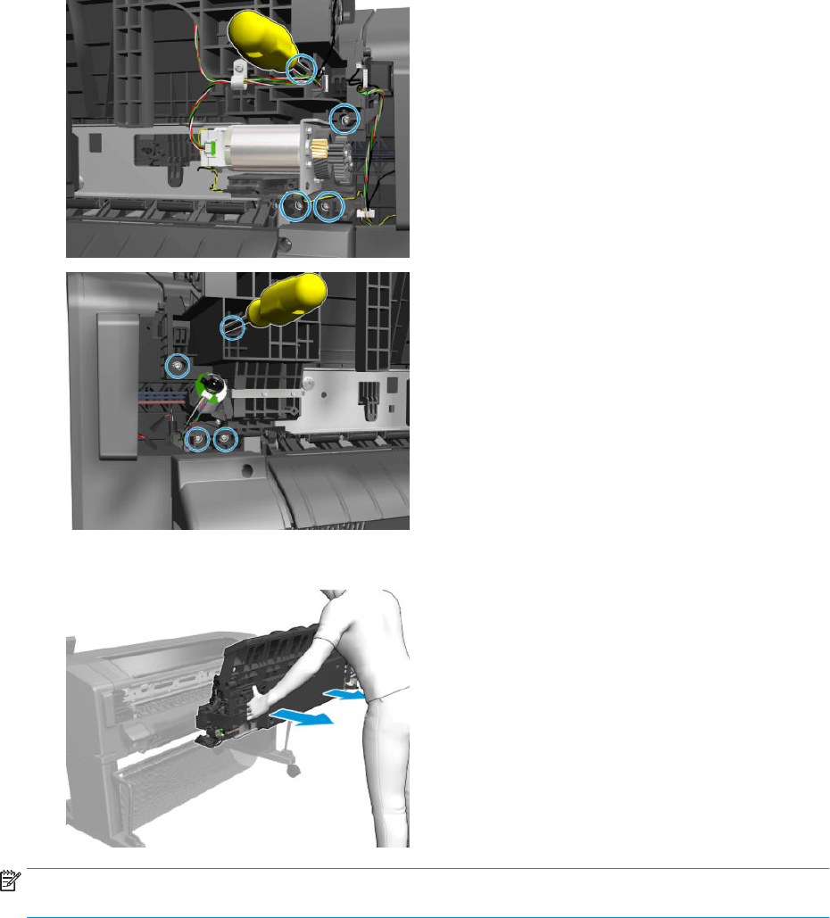
4. Remove 4 T-15 screws from both sides.
5. Remove the stacker, pulling the handles on the back.
NOTE: For installation make sure that the valves are down and the ramps are hidden, otherwise it can cause
improper assembly, and show SE90:03 or SE89:03.
406 Chapter 6 Removal and installation ENWW
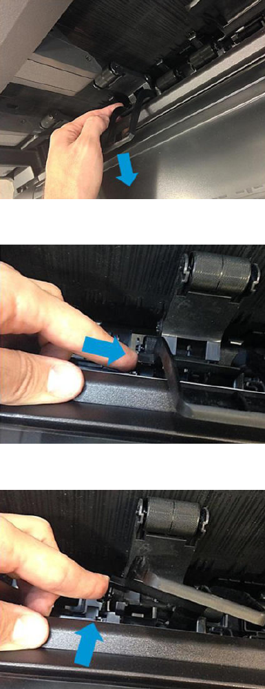
Stacker adaptor for MFP
T2500 only: installing adaption kit CR359-67006.
Removal of the old stacker wheel lifters
1. Pull the stacker wheel lifter towards you.
2. Push the stacker wheel lifter’s left leg to unclip it. Be sure not unclip the second wheel holder.
3. Slide the leg towards the foldable tray.
ENWW Stacker adaptor for MFP 407
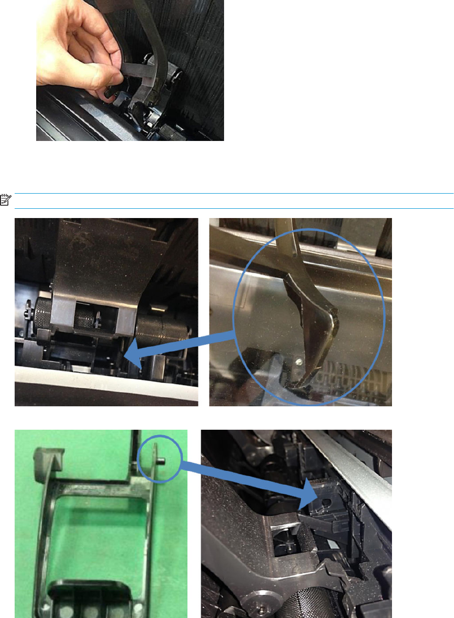
4. When the left leg is unclipped, the right leg will come out too. Remove each stacker wheel lifter.
Before assembling the MFP stacker wheel lifters, check the following reference images for guidance:
The hook of the stacker wheel lifter for MFP should be inserted into the hole shown by the blue arrow.
NOTE: This is easier to do when the stacker ramps are down.
The right pin of the stacker wheel lifter for MFP must slide into the groove shown by the blue arrow.
408 Chapter 6 Removal and installation ENWW
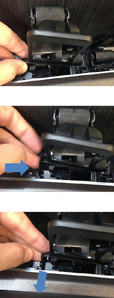
Assembling the MFP stacker wheel lifters
1. Insert the right leg in the hole and align the right pin as explained previously.
2. Push the stacker wheel lifter’s left leg to align the left pin with the left groove.
3. While pushing, slide the leg towards you. It clicks into place.
ENWW Stacker adaptor for MFP 409

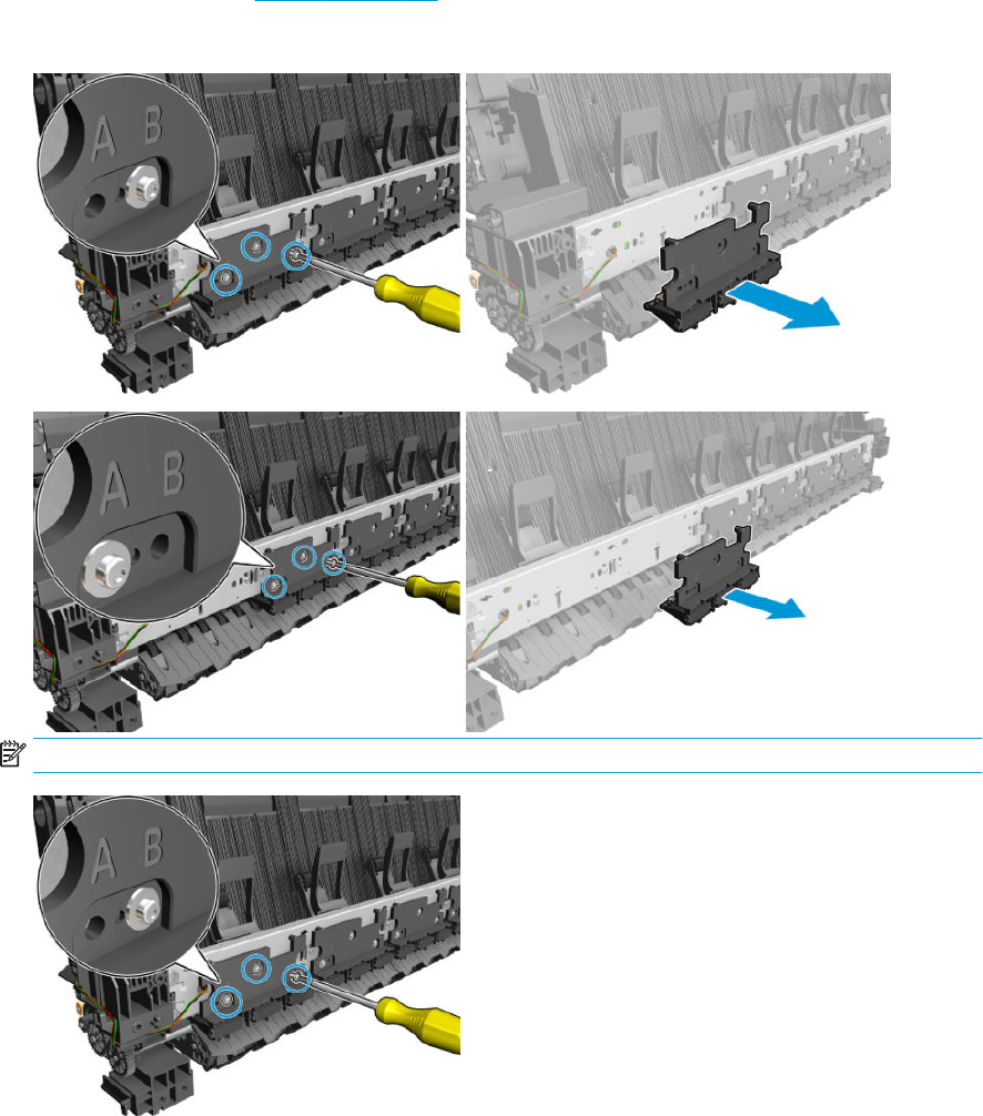
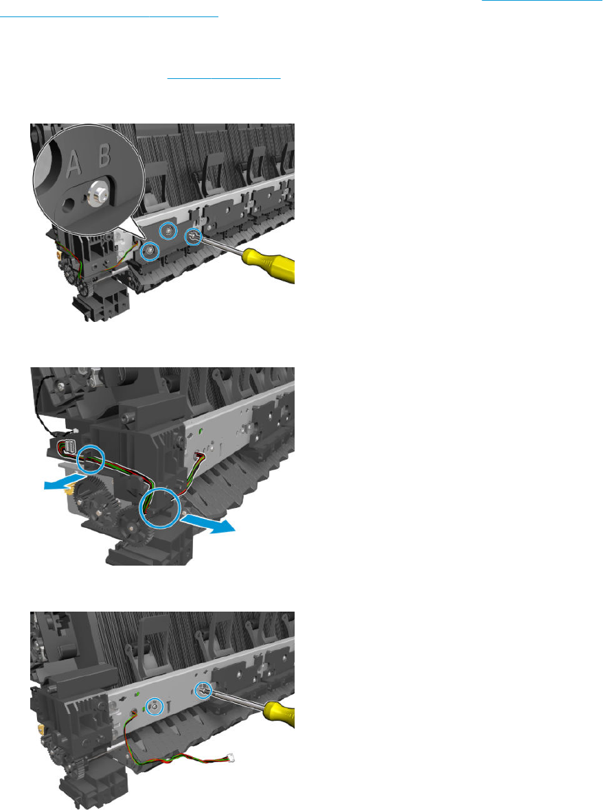
Stacker Hand O
T2500 only: In order to change the stacker hand of, you need rst install service kit. See Stacker Hand O Assy
Service Kit (CR357-67041) on page 413.
Removal
1. Remove the stacker. See Stacker on page 405.
2. Remove 3 T10 screws and the 1st pinch (B).
3. Unroute the cable.
4. Remove 2 T10 screws.
412 Chapter 6 Removal and installation ENWW
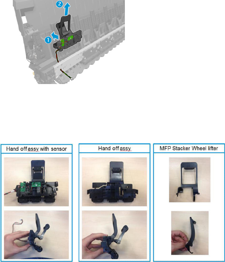
5. Remove the stacker hand o.
Stacker Hand O Assy Service Kit (CR357-67041)
T2500 only: the Stacker Hand O Assy (CR375-67041) includes parts needed to repair the MFP and single
function printer. Follow the steps below to assemble the part depending on the product.
Each service kit CR357-67041 (both for Single Function and MFP) includes:
Hand o assemblies come with single function stacker wheel lifters.
To install them in an MFP, rst you need to replace the 6 stacker wheel lifters with the MFP stacker wheel lifters
included in the same package.
Then, install the hand o assemblies following the service manual procedure.
Remove single function stacker wheel lifters
1. Rotate the stacker wheel lifter as shown by the arrow below to remove it.
ENWW Stacker Hand O Assy Service Kit (CR357-67041) 413
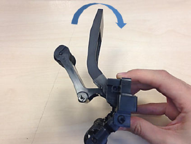
414 Chapter 6 Removal and installation ENWW
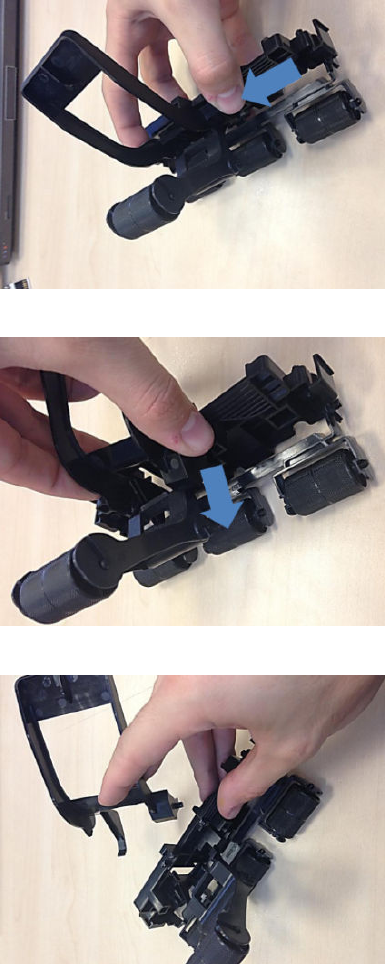
2. Press the right leg of the stacker wheel lifter to unclip it.
While pressing, slide the leg in the direction shown by the arrow.
The stacker wheel lifter is now removed from the Hand-o assembly.
Assemble multi-function printer stacker wheel lifters
1. Insert the hook through the hole shown below.
ENWW Stacker Hand O Assy Service Kit (CR357-67041) 415
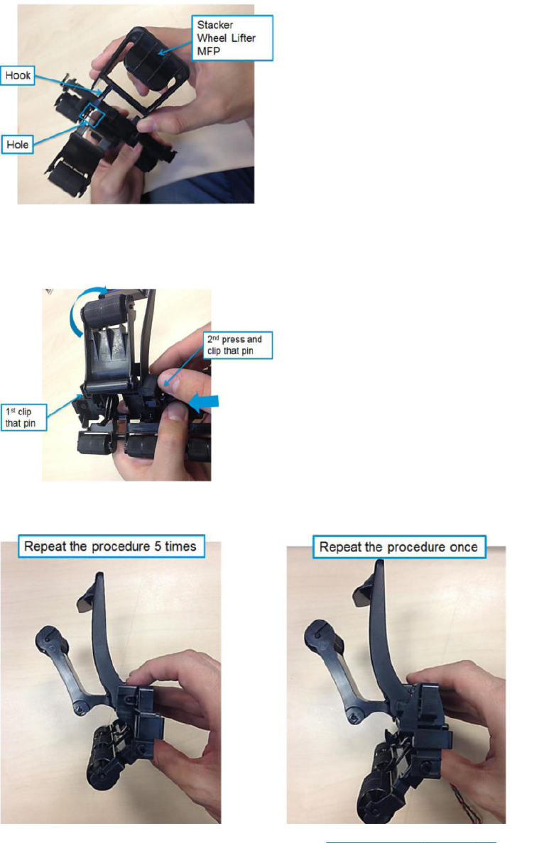
2. Rotate the second wheel holder in order to insert the right and left pin.
3. Clip the hook side pin into place, then press in the other leg to clip in the other pin.
4. Repeat all steps for each hand-o assembly, and for the hand-o assembly with sensor.
You can now proceed to change the stacker hand o. See Stacker Hand O on page 412.
416 Chapter 6 Removal and installation ENWW
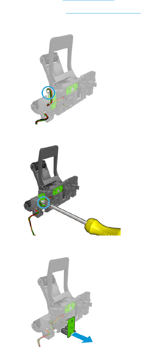
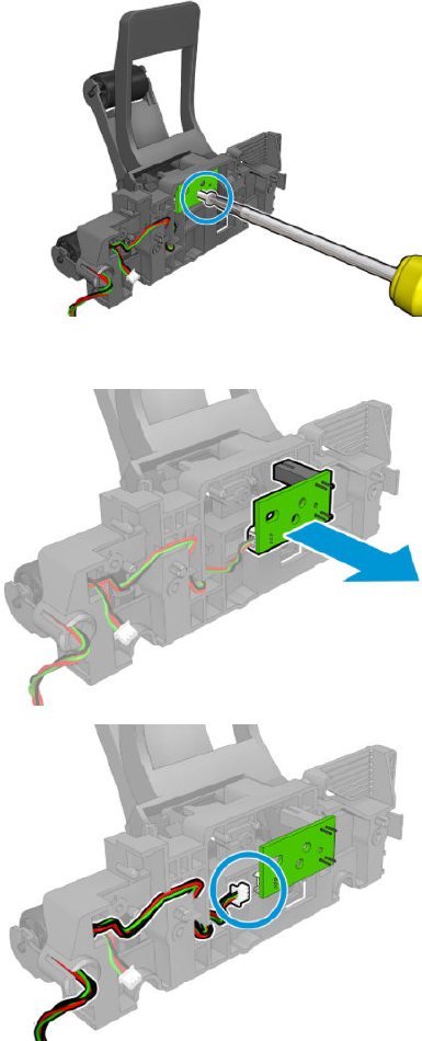
6. Remove the screw.
7. Remove the PCA and disconnect.
418 Chapter 6 Removal and installation ENWW
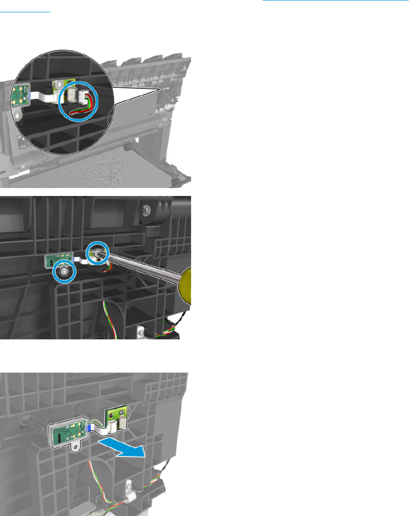
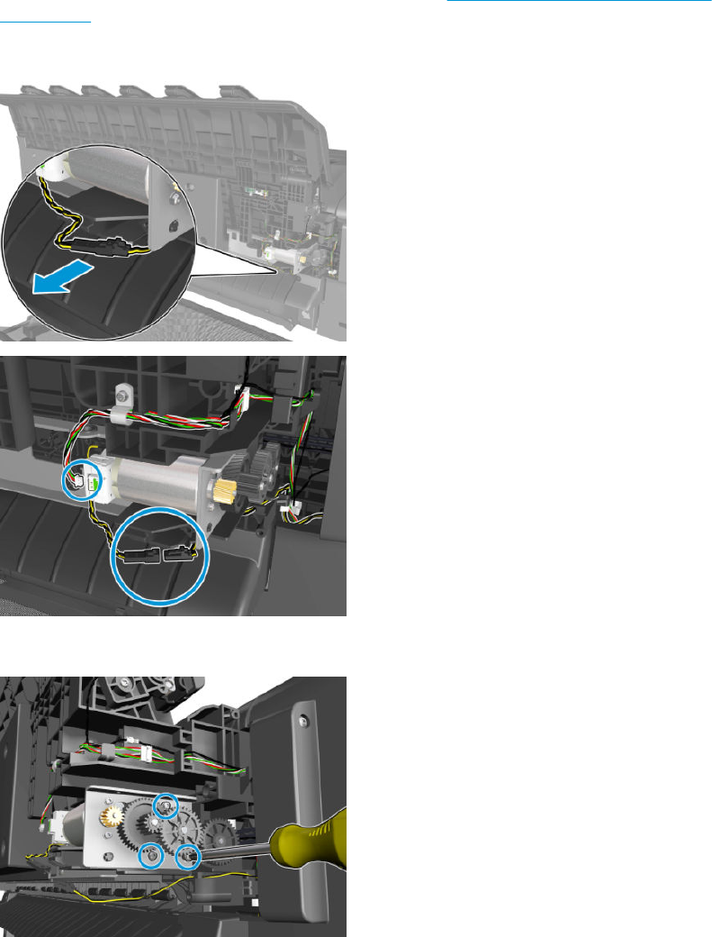
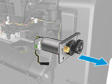
4. Remove the overdrive.
ENWW OVD Transmission with Motor 421
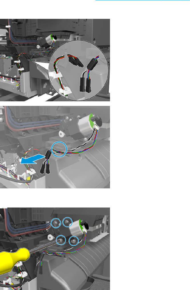
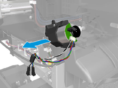
4. Remove the ramps motor.
ENWW Ramps Motor 423

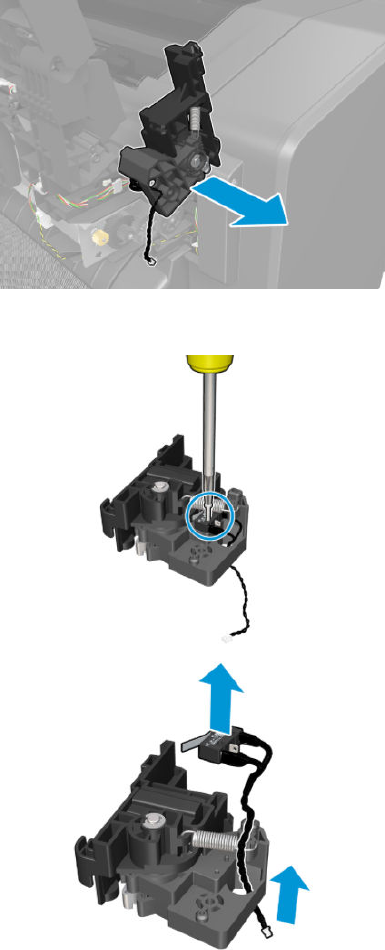
5. Remove the module.
6. Remove the screw and microswitch (sensor).
ENWW Stacker Arm Sensor 425
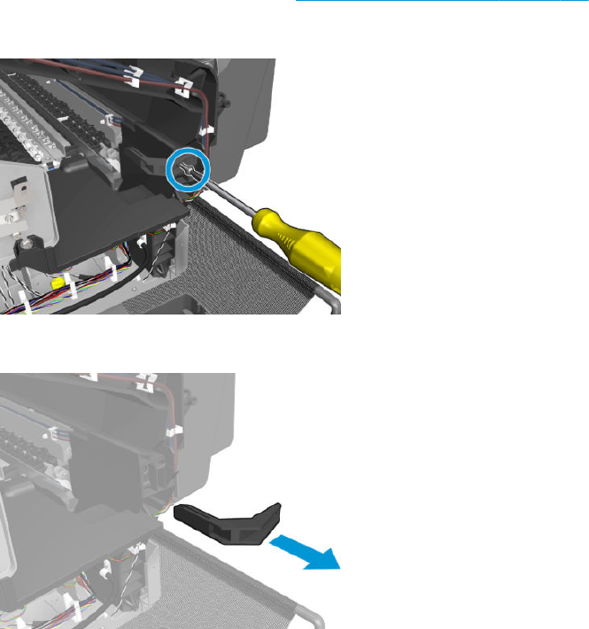
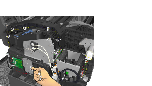

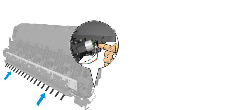
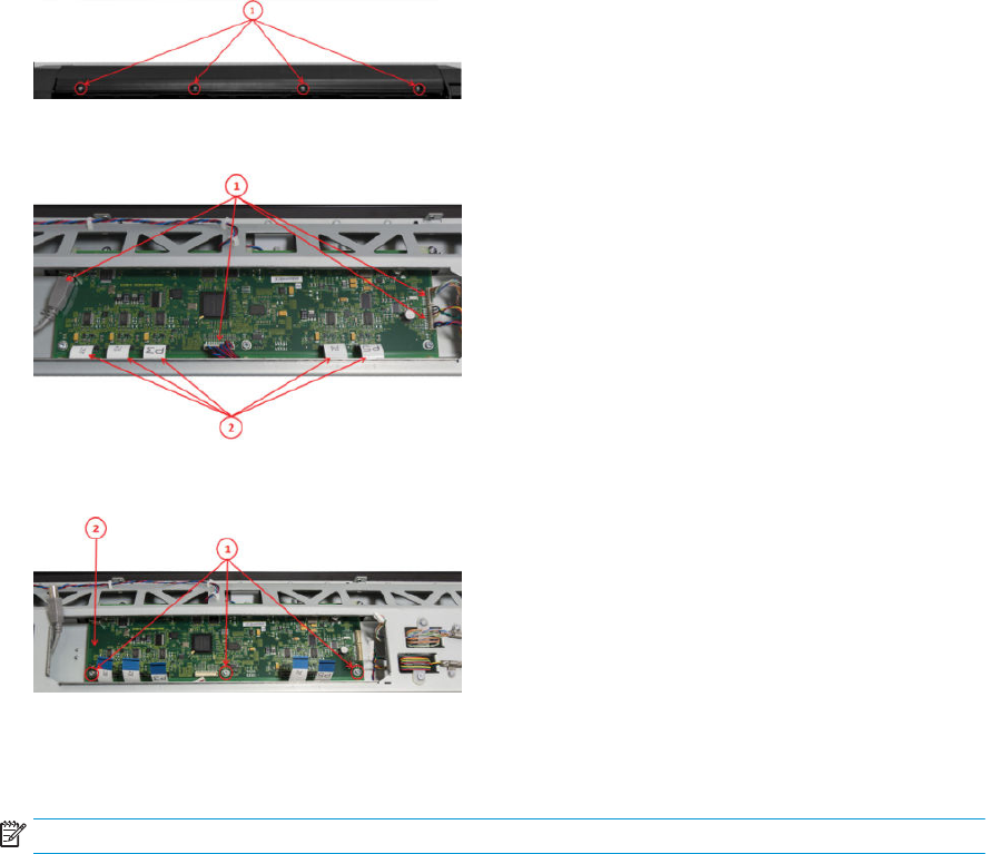
Scanner Controller Unit (SUP)
Removal
1. Turn the scanner o, disconnect the power cord, and tilt open the CIS bridge.
2. Remove the screws marked S1 (Torx 10), and open the CIS unit.
3. Disconnect the cables, release the ribbon cables lock (A), and pull out cable.
4. Remove the Screws (Torx 10), and remove the Scanner Controller Board.
Replacement
▲To replace reverse the removal steps.
NOTE: The new Scanner Controller Board needs to be calibrated.
430 Chapter 6 Removal and installation ENWW
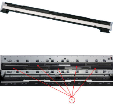
CIS Tiles
Removal
1. Remove the screws (Torx 10), and remove the idle roller cover sheet.
2. Remove the CIS tiles, and mark them for repositioning if necessary.
Replacement
1. If only the CIS tiles are being replaced; reverse the removal steps.
2. Re-calibrate the scanner.
ENWW CIS Tiles 431
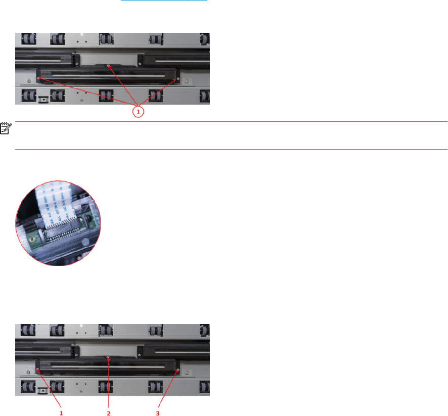
CIS Modules
Removal
1. Remove the CIS Tiles. See CIS Tiles on page 431.
2. Remove the screws marked S1 (Torx 10), and open the CIS unit.
NOTE: In order to remove the lower CIS modules the upper must be removed (there is no need to
disconnect).
3. Carefully disconnect by pulling.
Replacement
1. Replace the CIS module and tighten the screws in order 1 to 3.
2. Re-calibrate the scanner.
432 Chapter 6 Removal and installation ENWW
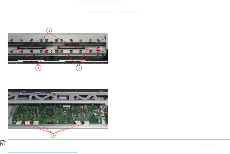
CIS FFC Cables
Removal
1. Remove the aected CIS Tiles. See CIS Tiles on page 431.
2. Remove the aected CIS Modules. See CIS Modules on page 432.
3. Replace the CIS module and tighten in order 1 to 3.
4. Unplug only the FFC cables that need to be replaced.
NOTE: For some of the cables it may be helpful to remove the Scanner Controller board. See Scanner
Controller Unit (SUP) on page 430.
ENWW CIS FFC Cables 433
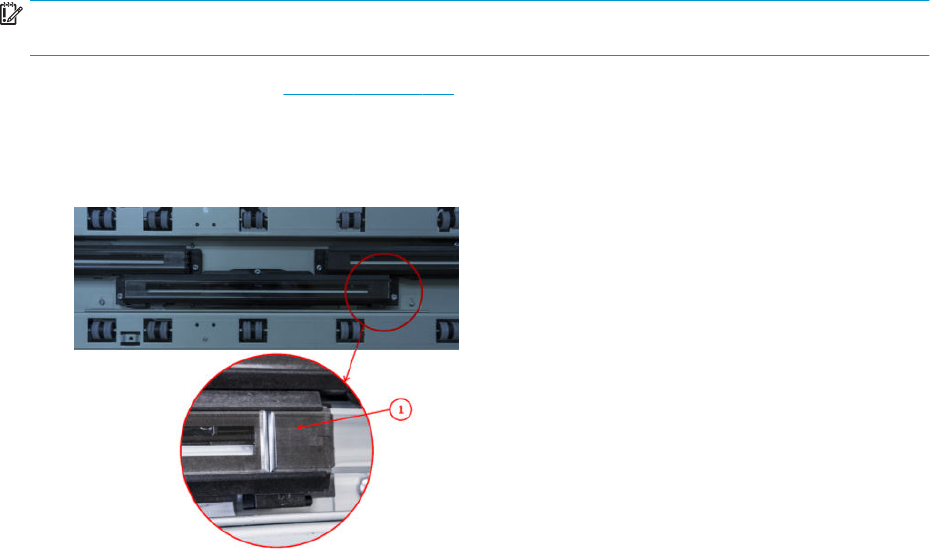
CIS Glass
Removal
IMPORTANT: Only replace glass when in a “clean” environment, and be careful not to touch the underside of
glass.
▲Remove the CIS Tiles. See CIS Tiles on page 431.
Replacement
1. Replace by carefully inserting the new glass, pushing the old one out.
2. Re-calibrate the scanner.
434 Chapter 6 Removal and installation ENWW
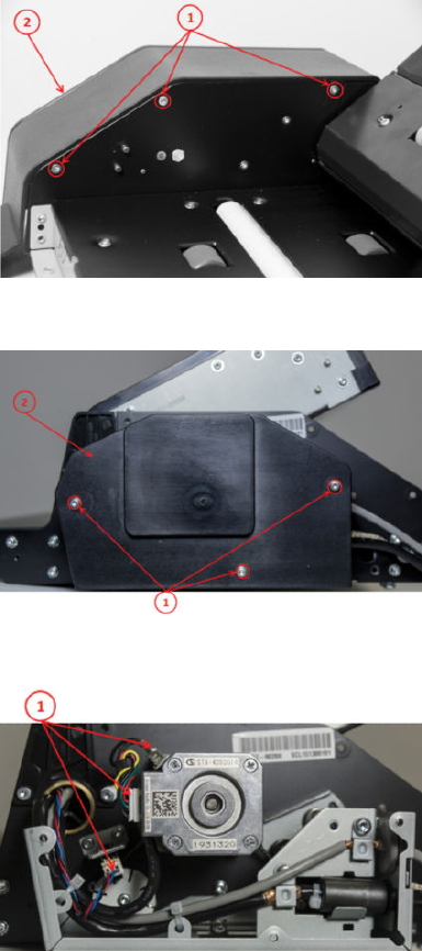
Stepper Motor Assembly (taco sensor, and belt)
Removal
1. Turn the scanner o, disconnect the power cord, and tilt open the CIS bridge.
2. Remove the screws (1) and then the scanner RHS cover (2).
3. Remove the screws (1), and then the motor cover (2).
4. Disconnect the Sensor Motor cables.
ENWW Stepper Motor Assembly (taco sensor, and belt) 435
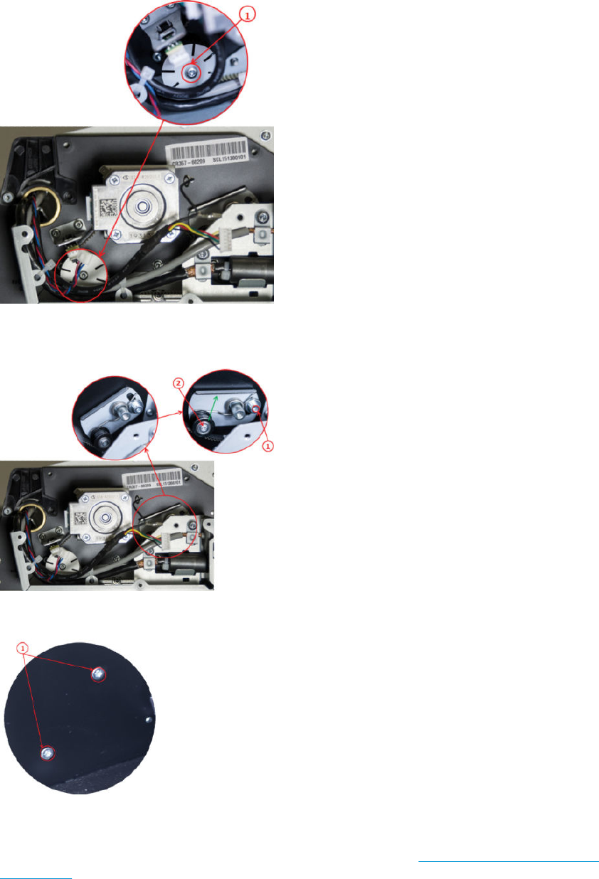
5. Loosen the screw (don’t remove it), and remove the Taco Wheel.
6. Release belt tension by loosening the screw (don’t remove it), and push the tension wheel upwards and
tighten the screw.
7. Remove the motor screws.
Replacement
▲Replace by reversing the removal steps. If the Cable is being replaced see Stepper Motor Assembly (cable)
on page 437.
436 Chapter 6 Removal and installation ENWW
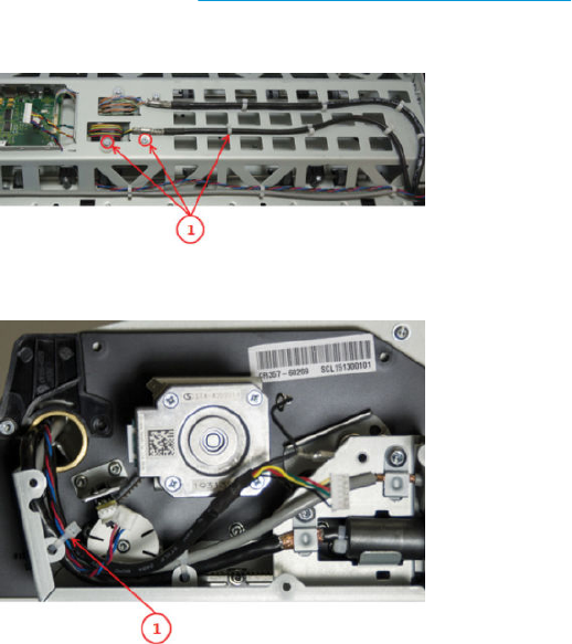
Stepper Motor Assembly (cable)
Removal
1. Open the CIS unit. See Scanner Controller Unit (SUP) on page 430.
2. Remove the screws, and unclip the cable.
3. Cut the cable tie, and push the cable into the CIS unit.
Replacement
▲Replace the cable by reversing the removal steps.
ENWW Stepper Motor Assembly (cable) 437
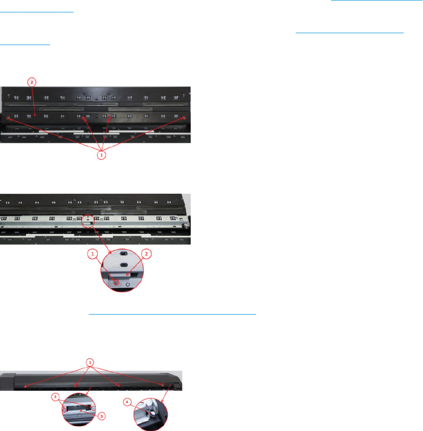
Paper and Lid Sensors
Removal
1. Turn the scanner o, disconnect the power cord, and tilt open the CIS bridge.
2. If replacing the Exit Sensor or the Lid Sensor, you will need to open the CIS unit. See Scanner Controller Unit
(SUP) on page 430.
3. If the sensor cable needs replacing, the Paper & Lid Sensor is aected. See Paper and Lid Sensor Cable
on page 440.
4. Remove the screws, and the roller cover.
5. Remove the screw (1), and the sensor bracket (2).
6. Open the CIS unit. See Scanner Controller Unit (SUP) on page 430.
7. Remove the screws and the CIS unit cover (1). Remove the screws (2), the sensor bracket (3), and
disconnect the Lid Sensor (4).
438 Chapter 6 Removal and installation ENWW
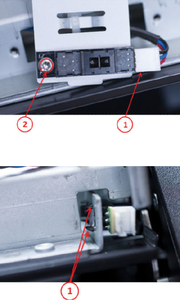
8. Disconnect the cable (1), remove the screw and Exit Sensor (2).
9. Squeeze lock pins, and remove the Lid Sensor.
Replacement
▲Replace by reversing the removal steps.
ENWW Paper and Lid Sensors 439
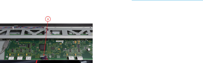
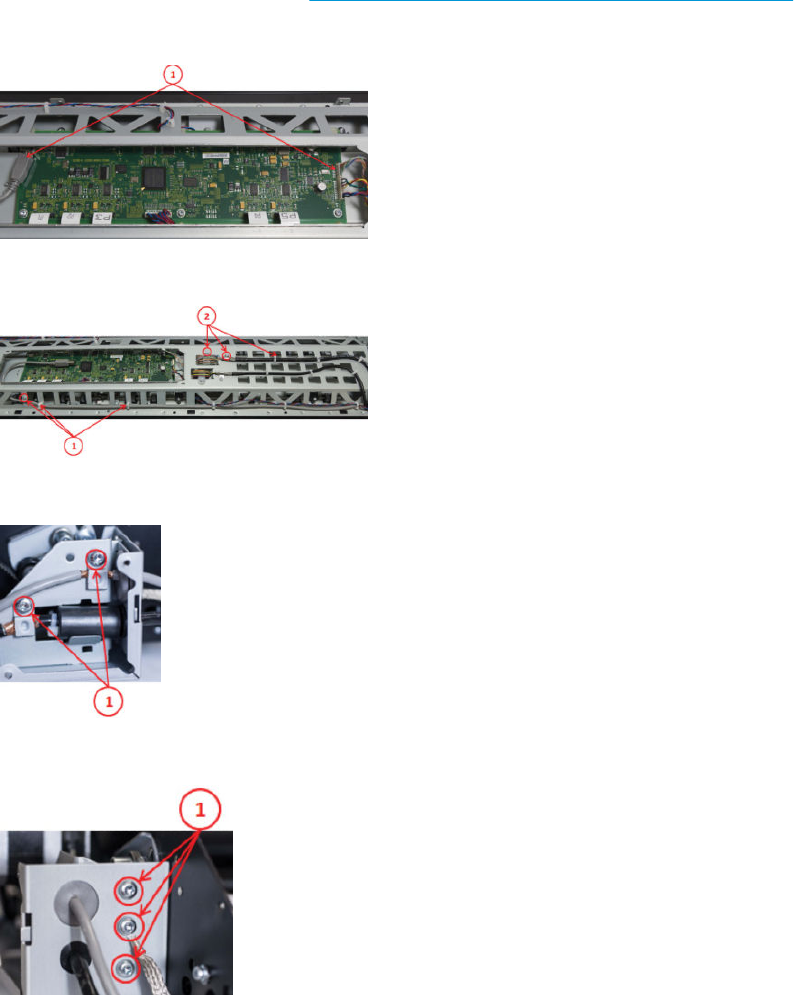
USB & Awake / Power Cable
Removal
1. Turn the scanner o, disconnect the power cord, and tilt open the CIS bridge.
2. Remove the RHS and Motor Cover. See Stepper Motor Assembly (taco sensor, and belt) on page 435.
3. Disconnect the USB & Awake / power cable (1). Unclip the cable throughout the CIS unit.
4. Unclip the USB Cable and pull it gently out of the CIS bridge (1). Remove the screws and unclip the cable (2).
5. Remove the screws.
6. Remove the screws.
ENWW USB & Awake / Power Cable 441
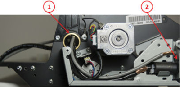
7. Carefully pull Cables into motor compartment (1 & 2).
Replacement
▲Replace by reversing the removal steps.
442 Chapter 6 Removal and installation ENWW
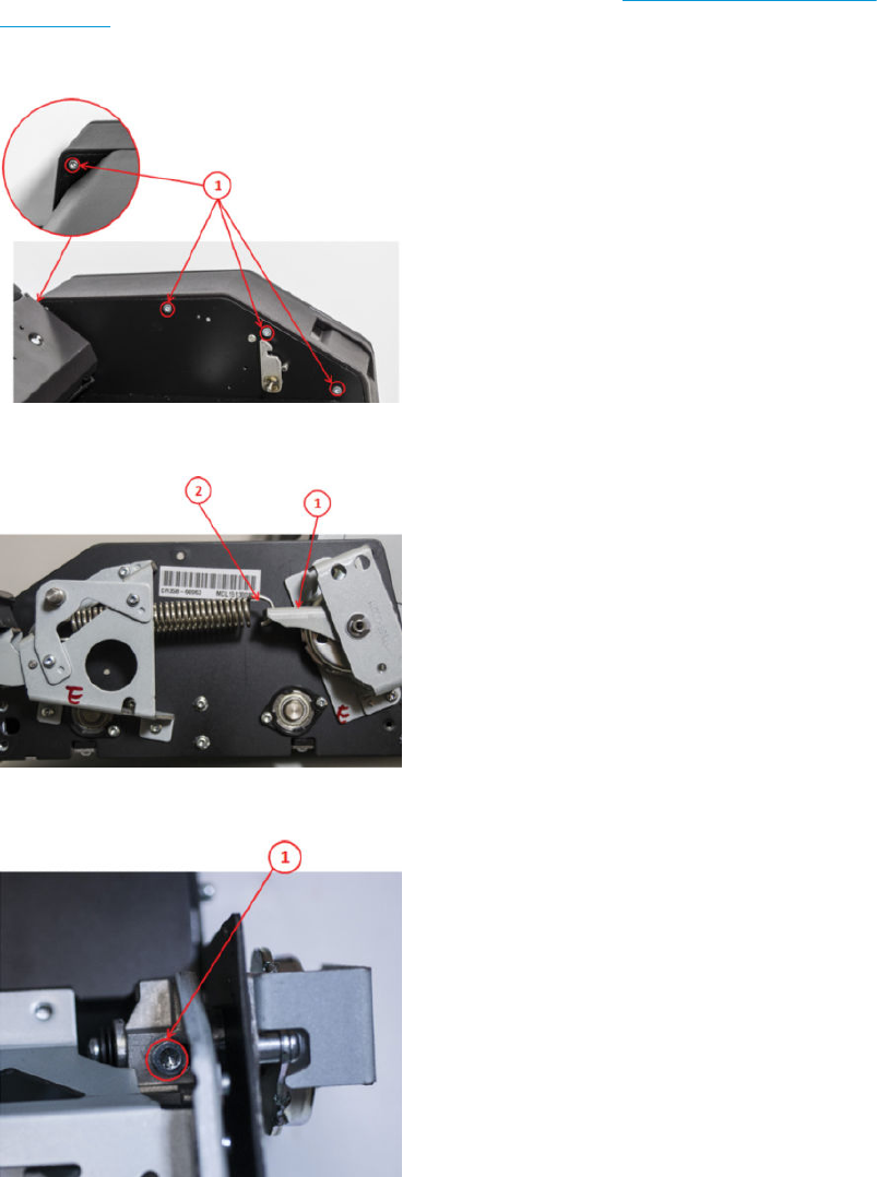
CIS Bridge Damper
Removal
1. Turn the scanner o, disconnect the power cord. Open the CIS Unit. See Scanner Controller Unit (SUP)
on page 430.
2. Remove the screws and LHS cover.
3. Tilt open the CIS bridge to decrease the spring tension (1), and unhook the spring (2).
4. Remove the screw and carefully free the CIS bridge.
ENWW CIS Bridge Damper 443
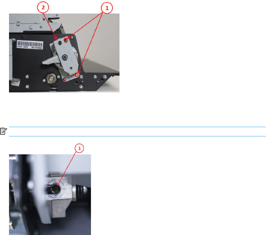
5. Tilt open the CIS bridge to decrease the spring tension (1), and remove CIS damper (2).
Replacement
▲Replace by reversing the removal steps.
NOTE: When replacing, be sure to align the holes and hold, when securing the screws (1).
444 Chapter 6 Removal and installation ENWW
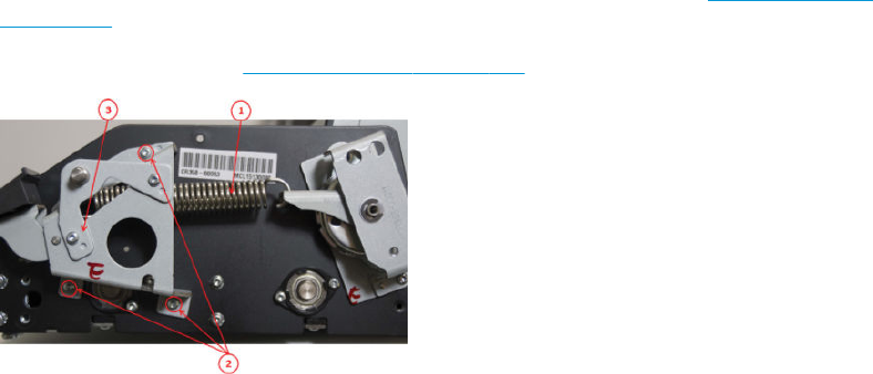
CIS Scanner Latch
Removal
1. Turn the scanner o, disconnect the power cord, and remove the LHS cover. See CIS Bridge Damper
on page 443.
2. Remove the spring (1). See CIS Bridge Damper on page 443. Remove the screws (2), and bracket (3).
Replacement
▲Replace the damper by reversing the removal steps.
ENWW CIS Scanner Latch 445
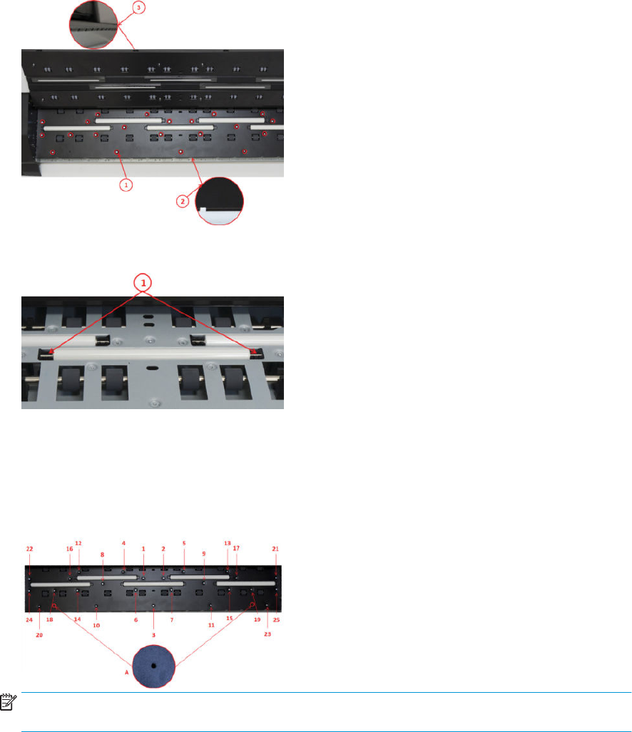
Pressure Rollers
Removal
1. Turn the scanner o, disconnect the power cord, and tilt open the CIS Bridge.
2. Remove the screws (Torx 10), and pull the Roller Cover sheet out through the back.
3. Gently pull the Pressure Roller out, and replace (repeat for all 5).
Replacement
1. After replacing the rollers, reverse the removal steps. Don’t forget to calibrate the scanner.
2. Insert all screws without tightening. Align the 2 holes (A). When all screws are inserted, tighten in order 1 to
25.
NOTE: If the white rollers were replaced due to stitching and/or alignment errors, the scanner needs to be
re-calibrated.
446 Chapter 6 Removal and installation ENWW
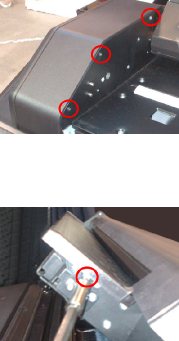
Front panel side scanner cover
Removal
1. Open the scanner cover.
2. Remove the 3 screws (Torx 10).
3. Close the scanner cover.
4. Open the scanner.
5. Remove 1 screw (Torx 10).
6. Remove the cover.
ENWW Front panel side scanner cover 447
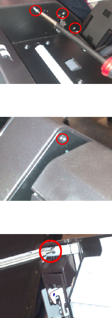
Service station side scanner cover
Removal
1. Open the scanner cover.
2. Remove the 3 screws (Torx 10).
3. Close the scanner cover.
4. Remove 1 screw (Torx 10).
5. Open the scanner.
6. Remove 1 screw (Torx 15).
7. Remove the cover.
448 Chapter 6 Removal and installation ENWW
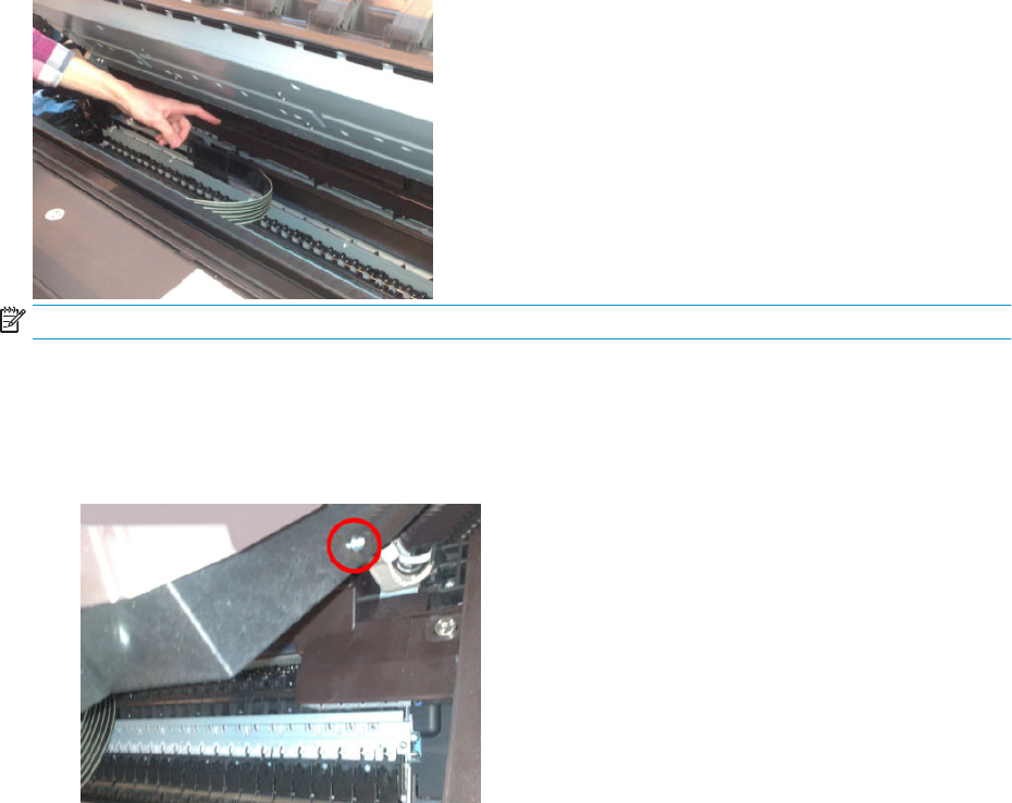
Rear scanner cover
NOTE: An angle screwdriver is needed, if not, you will have to remove scanner covers (FP and SVS side).
Removal
1. Open the scanner.
2. Remove 2 screws, 1 on each side (Torx 15).
3. Remove the rear cover.
ENWW Rear scanner cover 449
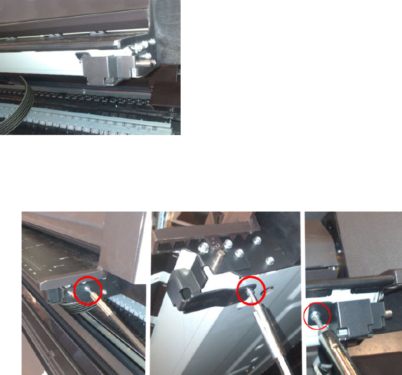
Bumper bracket
Removal
1. Open the scanner.
2. Remove 3 screws (Torx 10).
450 Chapter 6 Removal and installation ENWW
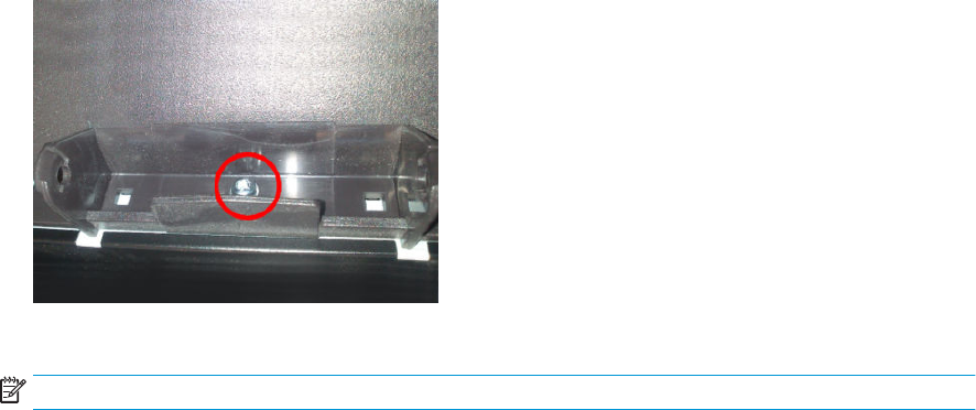
Deector hinge
Removal
1. Remove the deectors.
2. Remove the stacker arm cover.
3. Using a short screwdriver, remove 1 screw (Torx 20) from the hinge.
4. Remove the hinge.
NOTE: Deector hinges are not symmetrical, make sure you install the proper one.
ENWW Deector hinge 451
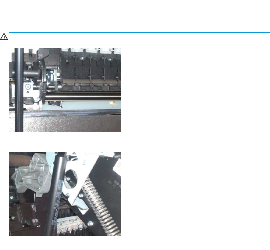
Lift assembly
Removal
1. Remove service station side scanner cover. See Service station side scanner cover on page 448.
2. Open the scanner.
3. Remove 1 screw (Torx15).
WARNING! Hold the scanner to avoid it falling. It is heavy.
4. Remove the circlip.
5. Remove the lift assembly. See Lift assembly on page 452.
452 Chapter 6 Removal and installation ENWW
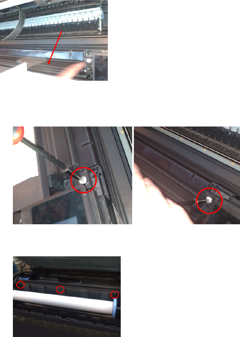
Scanner front beam bumper assembly
Removal
1. Open the scanner.
2. Remove 2 screws (Torx 15).
3. Open the upper roll cover.
4. Remove 3 screws (Torx 15).
5. Unhook the 2 hooks, and remove the bumper.
ENWW Scanner front beam bumper assembly 453
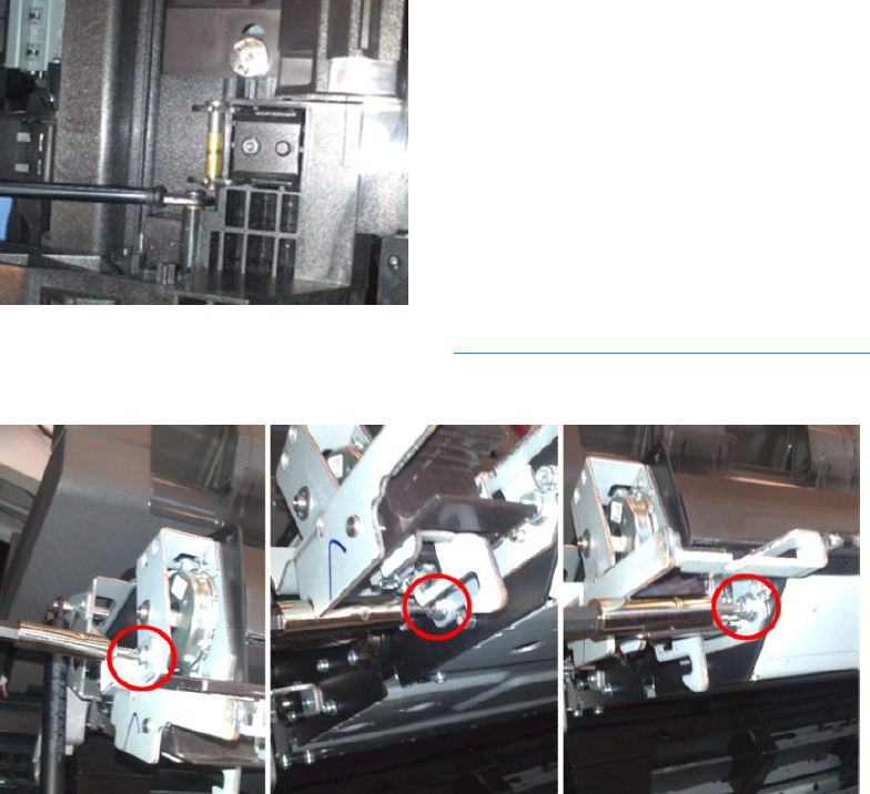
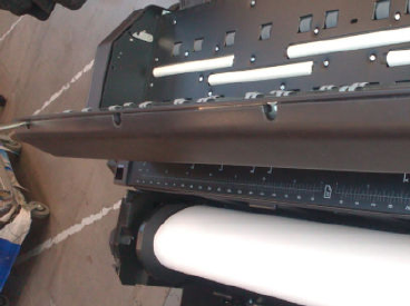
Top scanner cover
Removal
1. Open the scanner.
2. Remove 4 screws (Torx 15).
3. Close the scanner.
4. Remove the piece.
ENWW Top scanner cover 455
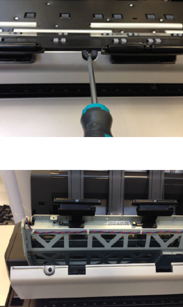
Batch scanning piece
Removal
1. Open the scanner cover.
2. Remove the 4 screws (Torx 15).
3. Open the scanner cover lid.
4. Replace the broken batch scanning piece.
456 Chapter 6 Removal and installation ENWW

Card Reader Accessory
API Technologies Corp provides Netgard Card Reader devices compatible with the HP Designjet T2500 ePrinter
series.
Setup and conguration
Setup requirements:
●MRY_02_00_03.4 rmware or later installed in the printer.
●The printer is connected to a router/switch that interfaces with.
●The Card Reader is connected to the router/switch.
●A WebApp developed by API is installed in the MFP.
What is provided?
●Outgoing printer information is blocked, stopping the ability to submit scans to the net unless the user
identies himself with an ID Card in the Card Reader.
●The Scan and Copy Icons are removed from the Front Panel.
●The scanned jobs are removed from the queue.
Support
HP is not supporting the Card Reader. This is supported by the Card Vendor.
In case of network problems, try these troubleshooting steps:
●Unplug the printer from the secured network and try directly connecting it to a PC or an open unsecured
network, then try to reproduce the issue.
●Uninstall the WebApp and try to reproduce the issue.
ENWW Card Reader Accessory 457


Preventive Maintenance
Cleaning the Product
To maintain the product in good operating condition, keep it free of accumulated dust, ink, and other
contamination. Cleaning intervals are determined by the product environment and by the types of product
supplies used.
General Cleaning
Proper general cleaning should include the following:
NOTE: To prevent electric shock, make sure that the product is switched OFF and unplugged before any
cleaning is performed. Do not let any water get inside the product.
1. Blow away dust accumulation with compressed air if available.
2. Clean the outer surface of the product with a damp sponge or cloth. Use a mild soap and water solution if
necessary. Do not use abrasive cleaners.
3. Wipe the product dry with a soft lint-free cloth.
Cleaning the Drive Roller
NOTE: If ink is spilled on the Overdrive, remove the ink. Due to the ink's reectance, ink on the Overdrive can
disrupt the product's edge-sensing function. To remove any ink from the Overdrive, perform the following
procedure: Prevent water or other liquids from running onto electrical components or circuits, or through
openings in the Electronics Module.
1. Perform the Turn Drive Roller Utility. See Turn Drive Roller.
2. Open the Window.
3. Apply any common household cleaning solution (water based only) to a soft, lint-free rag and apply it to
the Drive Roller and Overdrive surface while it is rotating. Make sure that you thoroughly clean the Drive
Roller and Overdrive surface.
4. Press Enter when you have completed the cleaning procedure.
5. Allow the Drive Roller to dry before loading paper in to the product.
Cleaning the Encoder Strip
1. Make sure that the product is not printing and that the Carriage Assembly is located at the front panel side
of the product. Turn o the printer.
ENWW Preventive Maintenance 459
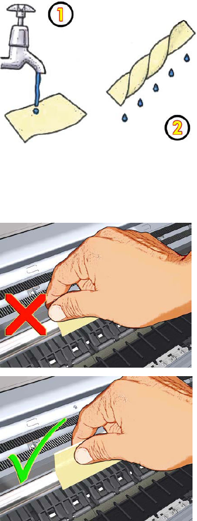
2. Using tap water and a small cloth that will not leave bers in the product, dampen the cloth and remove
any excess water so that the cloth is damp but not wet.
3. Open the Window.
4. Hold the cloth in an inverted “U” shape around the Encoder Strip and carefully wipe until no ink residue
appears on the cloth. Be very careful not to scratch the Encoder Strip with your ngernail or any other
object. Make sure that you are holding the cloth correctly.
5. Open the window and move the Carriage Assembly further to the left, allowing you to access the front
panel side.
6. Turn the product back on.
460 Chapter 7 Maintenance ENWW
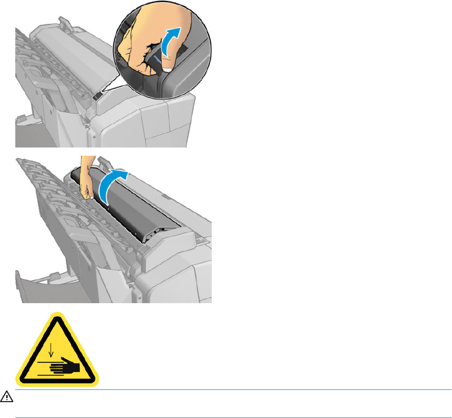
Clean the scanner’s glass plate
You are recommended to clean the scanner's glass plate periodically, depending on how often you use the
scanner.
1. Turn o the printer using the Power key at the front, then also turn o the power switch at the rear and
disconnect the power cable.
2. There is a small lever at the rear left of the scanner. Slide the lever up and open the scanner cover.
WARNING! Do not lift the scanner while the scanner cover is open. Your ngers or hand may be trapped or
crushed.
ENWW Preventive Maintenance 461
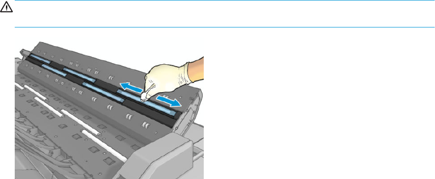
3. Gently wipe the glass plate and the surrounding area with a lint-free cloth dampened with water and then
wrung dry. A suitable cloth is provided with the printer.
CAUTION: Do not use abrasives, acetone, benzene or uids that contain these chemicals. Do not spray
liquids directly onto the scanner glass plate or anywhere else in the scanner.
Do not worry about tiny droplets of water left on the glass: they will evaporate.
4. Optionally, for more thorough cleaning:
●Remove the glass plate and clean it on both sides.
462 Chapter 7 Maintenance ENWW
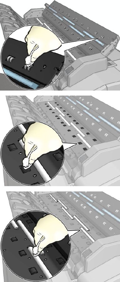
●Clean the pressure rollers and the feed rollers.
ENWW Preventive Maintenance 463
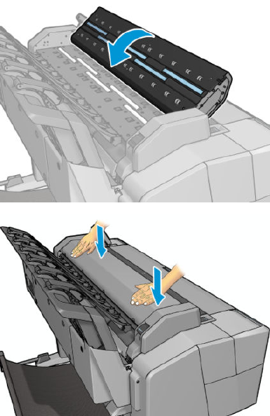
5. Close the scanner cover and gently push it down to lock it into place.
6. Clean the area immediately in front of the scanner, where the scanned sheet rests before scanning.
7. Reconnect the printer's power cable, turn on the power switch at the rear, and turn on the printer using the
Power key.
Carriage Assembly Lubrication
To ensure correct operation of the product you must lubricate the Carriage Assembly whenever any of the
following are encountered if:
●The Front Panel displays "Maintenance #1 required".
●There is excessive noise when moving the Carriage Assembly.
●A shut down of the carriage PWM error message appears.
●There are IQ (vertical banding problems). You should also lubricate the Carriage Assembly whenever you
change any of the following service parts:
●The Carriage Rear Bushing.
●The Carriage Assembly.
●The Carriage Rail Oiler.
To lubricate the Carriage Assembly you will require the Lubrication Kit (Q5669-60692). Use the following
procedure to lubricate the Carriage Assembly:
464 Chapter 7 Maintenance ENWW

1. Use the IPA alcohol (Q6675-60070) and the cleaning cloth to clean the Carriage Rail and the Carriage Slider
Rod. Do not use IPA alcohol in California or other areas that restrict the volatile organic compound (VOC)
content of cleaning solvents. A regulatory compliant alternate should be used.
2. Use an Oil Dispenser (Q6675-60062) to lubricate the Carriage Rail and the Carriage Slider Rod.
3. Replace the Carriage Rail Oiler with the new one contained in the kit and add 2 or 3 drops of oil to the foam
of the Carriage Rail Oiler.
4. Use an Oil Dispenser (Q6675-60062) to lubricate the Carriage Rear Bushing.
Moisture on the Product
Users should use the product in an environment between 20% and 80% relative humidity. To recover from
moisture condensation, turn the product O, and, using the main roller as a reference, wait until the product is
completely dry before using it again.
Noisy Carriage Bushing
To prevent noisy movement of the carriage, remove aluminum or dust particles from the bushing at the back of
the carriage, and from the slider path along which the bushing moves. Lubricate the slider path using the
Lubrication Kit (Q5669-60692).
Noisy Service Station
To prevent or to remove squeaking noise coming from Service Station side of the printer, please follow next
steps:
NOTE: This noise does not aect to the functionality of the printer.
Troubleshooting:
●The squeaking noise is related with friction in the gears of transmission plate of the Service Station
●Make sure that the printer has the latest rmware installed, available from: www.hp.com/go/T1500/
software
●Get a new lubrication kit: CR357-67090 Mercury Grease Kit 3cc Syringe
Each Mercury Grease Kit 3cc Syringe (CR357-67090) contains:
●Nitrile Gloves x 1 pair
●Lubricant 6040-1451 in 3cc syringe set
●2” x 2” Lint Free Cotton
ENWW Preventive Maintenance 465
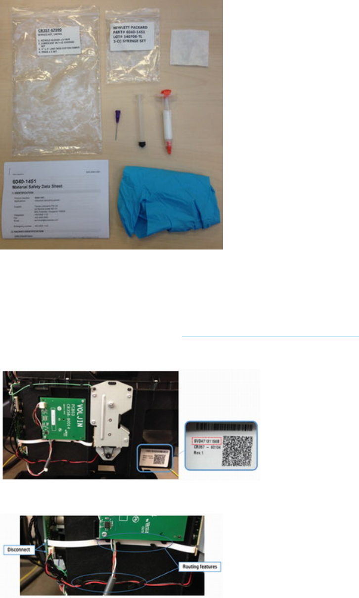
●MSDS
Application instructions
1. Power o the printer.
2. Record printer Serial Number (CNxxxxxxx).
3. Remove Main Cover (service station side). See Main cover (service station side) on page 283.
4. Record Service Station Serial Number. See image below.
5. Disconnect and take out from route location the encoder cable and motor cable.
466 Chapter 7 Maintenance ENWW
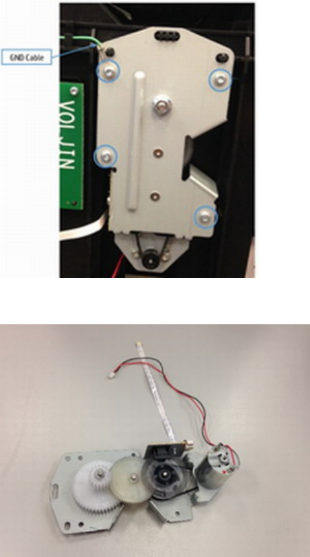
6. Loosen the 4 screws and the grounding cable.
7. Place the transmission plate on a table.
ENWW Preventive Maintenance 467
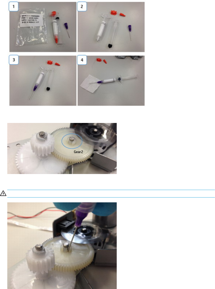
8. Open the bag 6040-1451. Mount the syringe.
9. Grease must be applied in both slots that are in the Gear 2.
10. Place the tip of the needle in the slot and inject grease until it covers the slot. Repeat this step in both slots.
CAUTION: Be careful to not stain with grease the encoder.
468 Chapter 7 Maintenance ENWW
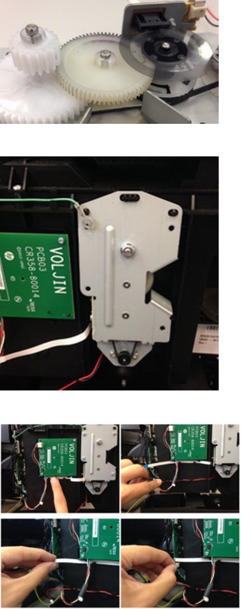
11. Clean the remaining grease with the lint free cotton. After cleaning it should look like in the image below.
12. Reassemble the Transmission Plate in the Service Station. First screw the Grounding Cable.
13. Route the cables carefully and reconnect them again.
ENWW Preventive Maintenance 469
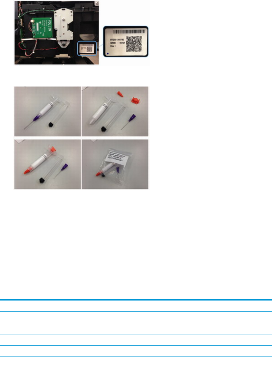
14. Mark with a dot at the left bottom of the Service Station label to have a visual check of the reworked units.
15. Disassemble the syringe and save it for the next time.
Belt Swelling
To prevent new belts from swelling incorrectly, keep them in their bags with desiccant until you need to install
them.
Level of Product Usage
Normal product use means 3,000,000 Carriage Cycles (which corresponds to approximately 32,000 A0 prints on
average). Under normal usage conditions, it will be approximately 5 years before the product needs
maintenance. If the product is used more than the normal usage conditions, then it will need maintenance
service much more frequently.
One of the EEROM counters is assigned to counting the number of carriage cycles.
Service Part LIFE_VALUE Maintenance Advice
Belt Cycles 3,000,000 PMKIT1
Bushings Life 3,000,000 PMKIT1
Trailing Cable Cycles 3,000,000 PMKIT1
Scan Axis Cycles 3,000,000 PMKIT1
Scan Axis Distance Covered 4,500,000 PMKIT1
470 Chapter 7 Maintenance ENWW

Service Part LIFE_VALUE Maintenance Advice
Tubes Cycles 3,000,000 PMKIT1
Service Station Volume 750,000,000 PMKIT2
When these components of the product exceed this amount, the Front Panel displays the following message:
"Maintenance #1 required"
"Maintenance #2 required"
Once one of the maintenance advised messages is displayed, the relevant preventive maintenance kit must be
used to replace the most worn parts of the product. See Removal and Installation when replacing the necessary
parts.
ENWW Preventive Maintenance 471

Preventive Maintenance Kits
There is no preventive maintenance kit for the cutter, which is expected to last for the life of the product.
Preventive Maintenance Kit #1 (CR357-67072)
●Scan Axis Motor
●Belt
●Carriage
●Cutter
●Carriage PCA
●Encoder Strip
●Ink Tubes and Trailing Cable
NOTE: The Lubrication Kit is not included in the Preventive Maintenance Kit.
Preventive Maintenance Kit #2 (CR357-67073)
●Service station
●Line Sensor
472 Chapter 7 Maintenance ENWW

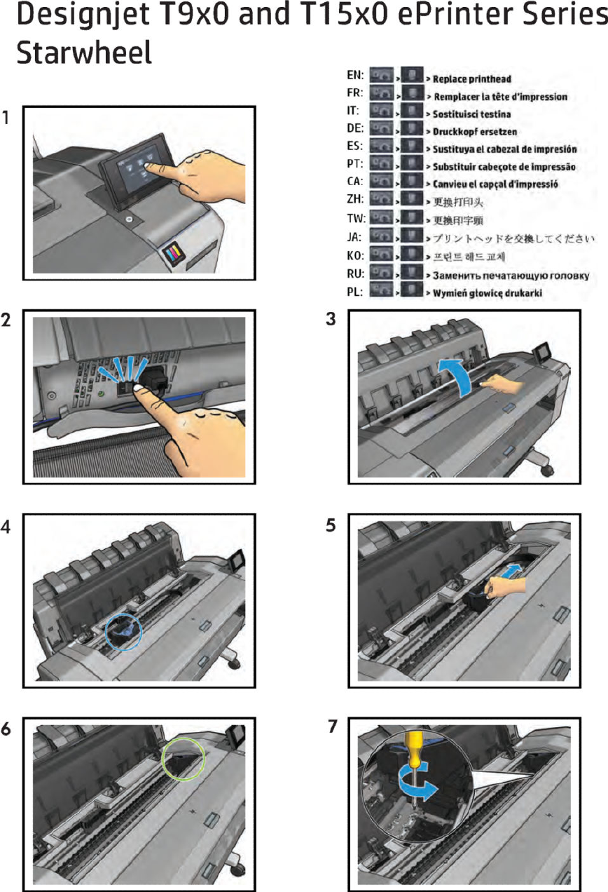
Starwheel
474 Chapter 8 Customer Self Repair Flyers ENWW
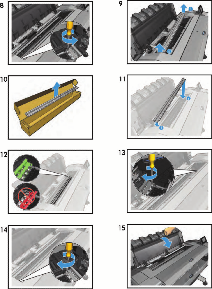
ENWW Starwheel 475
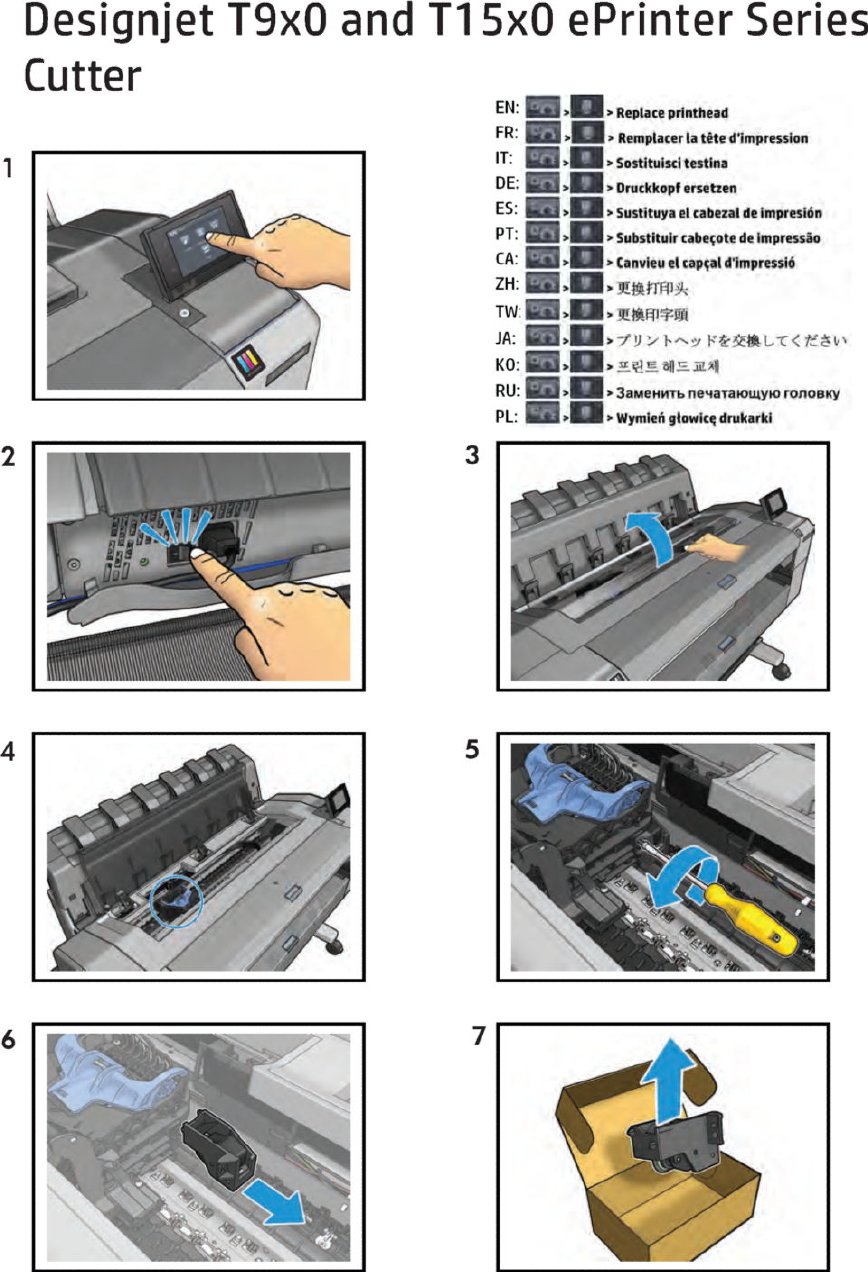
Cutter
476 Chapter 8 Customer Self Repair Flyers ENWW
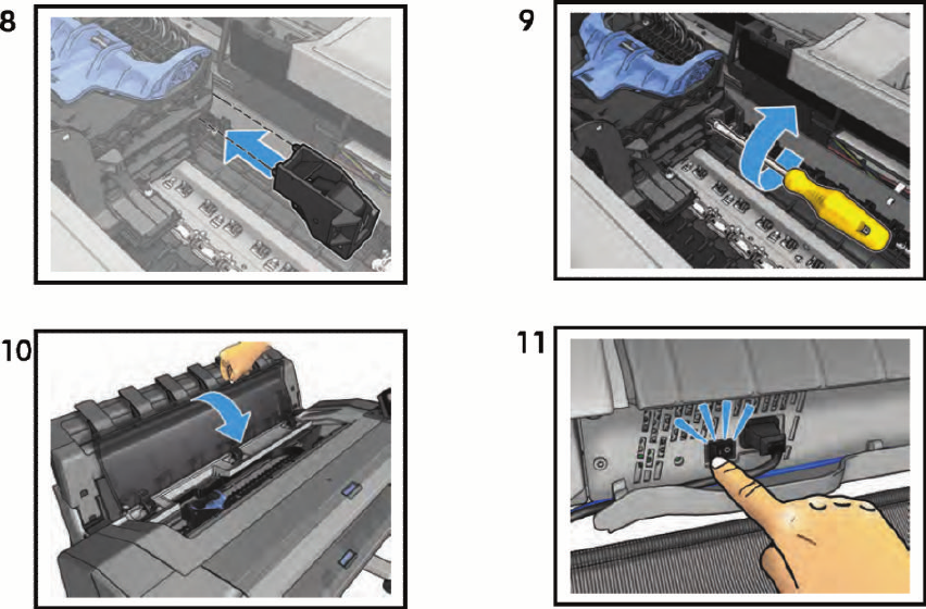
ENWW Cutter 477
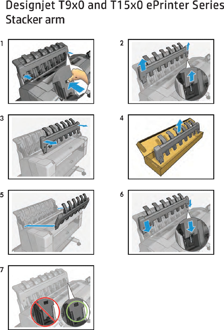
Stacker arm
478 Chapter 8 Customer Self Repair Flyers ENWW
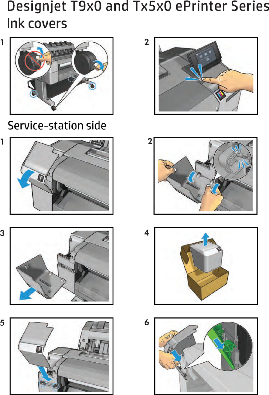
Ink covers
ENWW Ink covers 479
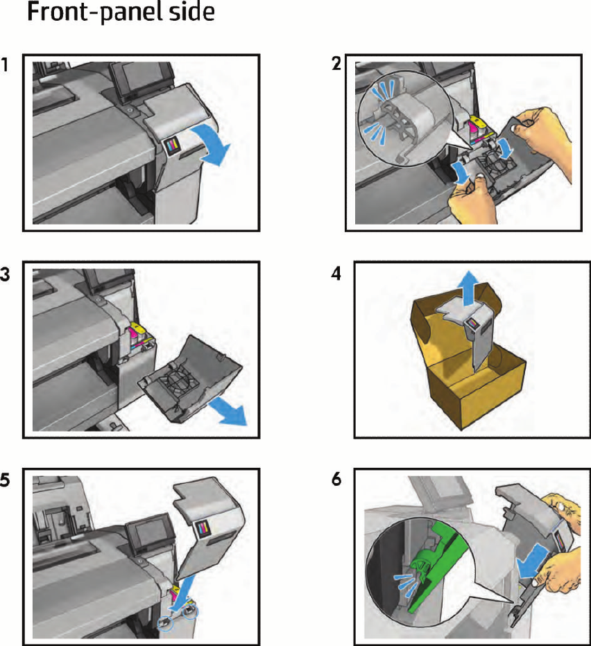
480 Chapter 8 Customer Self Repair Flyers ENWW
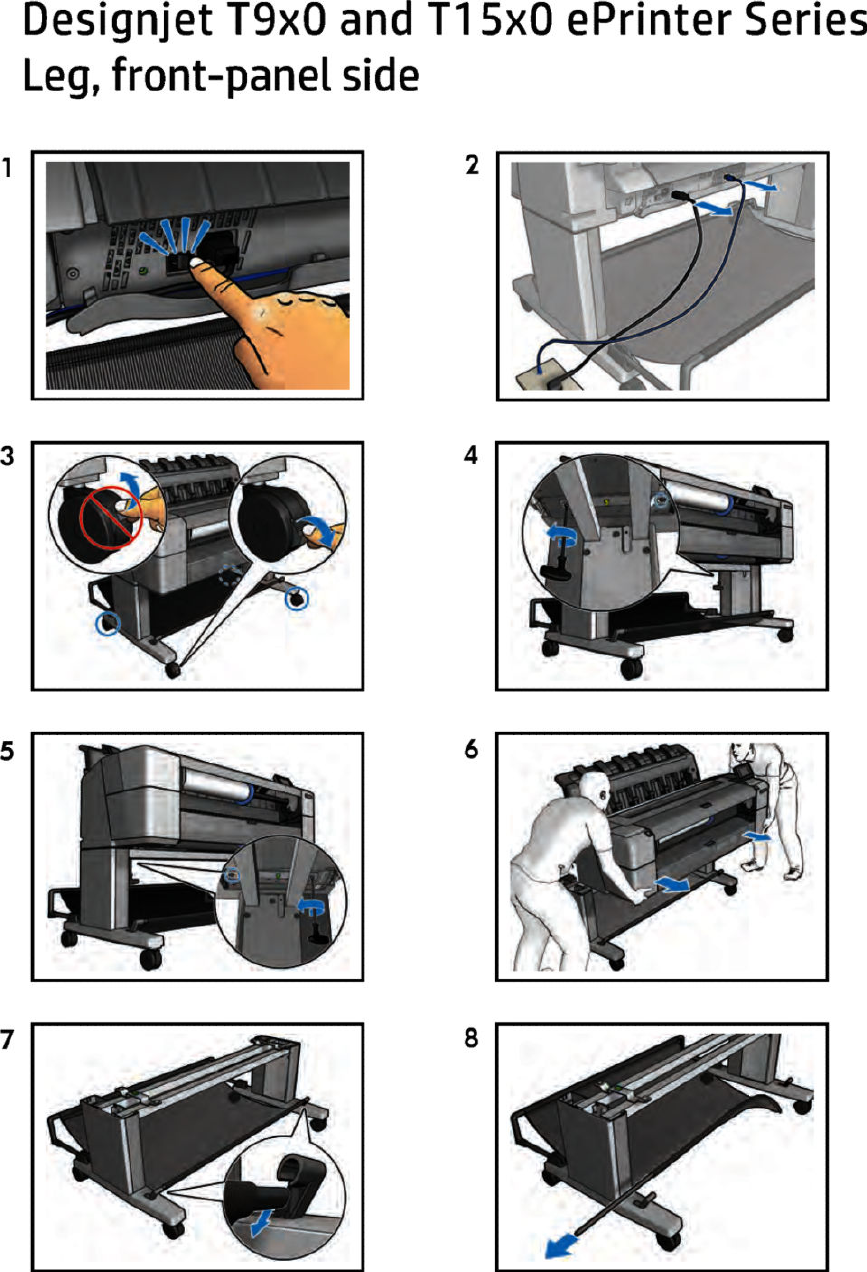
Leg, front-panel side
ENWW Leg, front-panel side 481
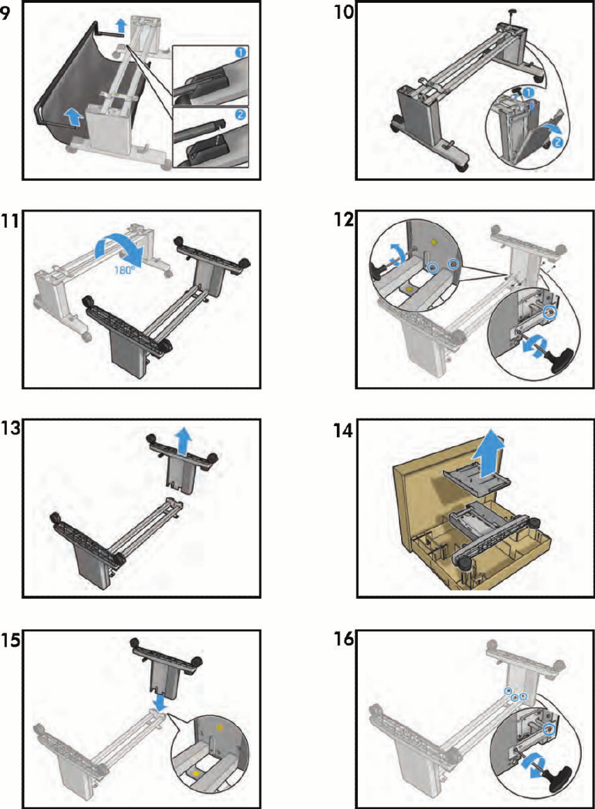
482 Chapter 8 Customer Self Repair Flyers ENWW

ENWW Leg, front-panel side 483

Leg, service-station side
484 Chapter 8 Customer Self Repair Flyers ENWW
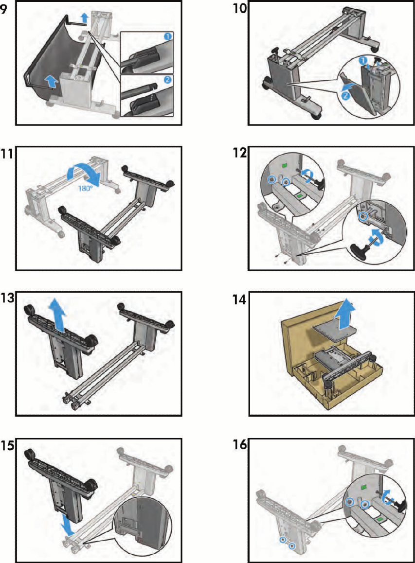
ENWW Leg, service-station side 485
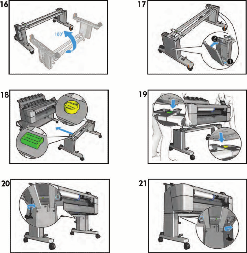
486 Chapter 8 Customer Self Repair Flyers ENWW
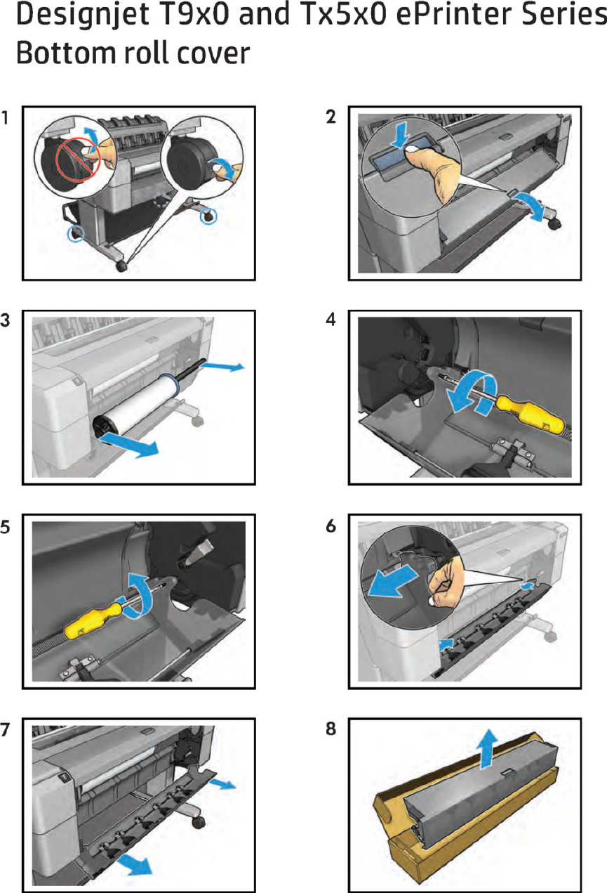
Bottom roll cover
ENWW Bottom roll cover 487
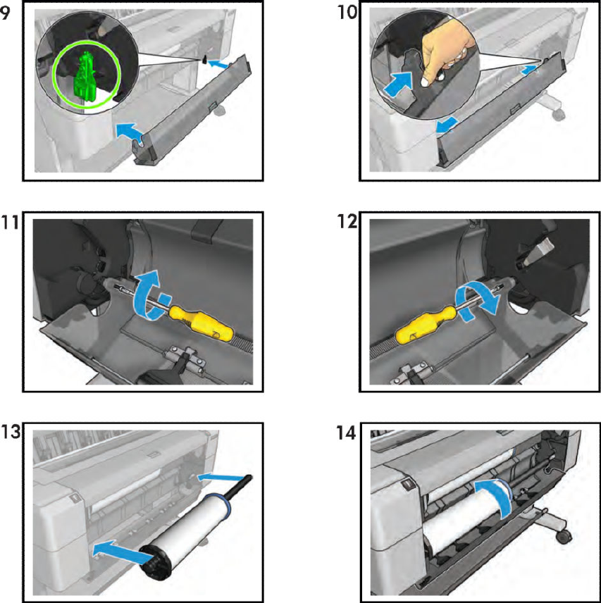
488 Chapter 8 Customer Self Repair Flyers ENWW
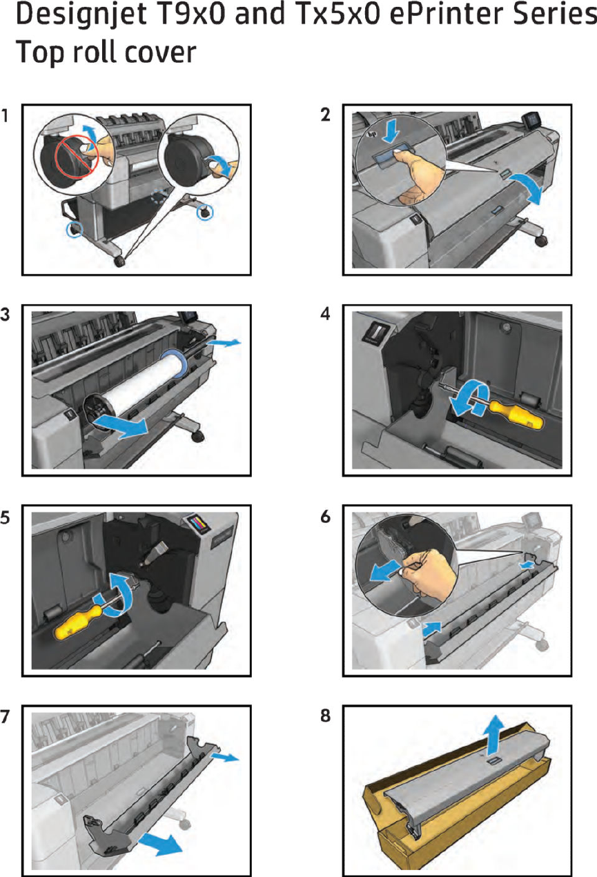
Top roll cover
ENWW Top roll cover 489
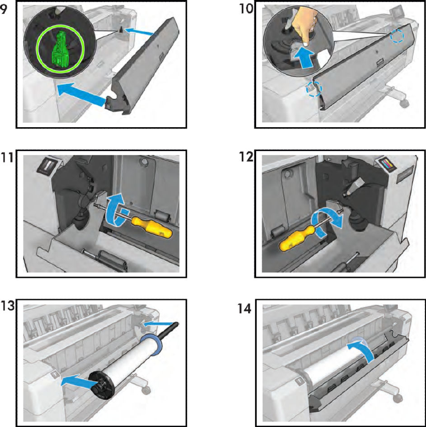
490 Chapter 8 Customer Self Repair Flyers ENWW
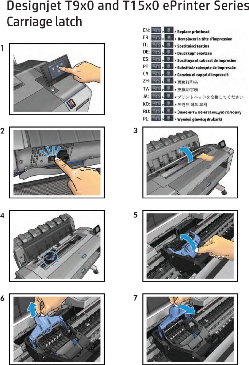
Carriage latch
ENWW Carriage latch 491
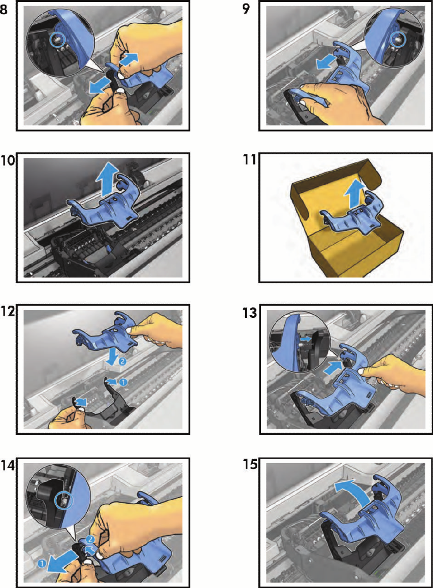
492 Chapter 8 Customer Self Repair Flyers ENWW
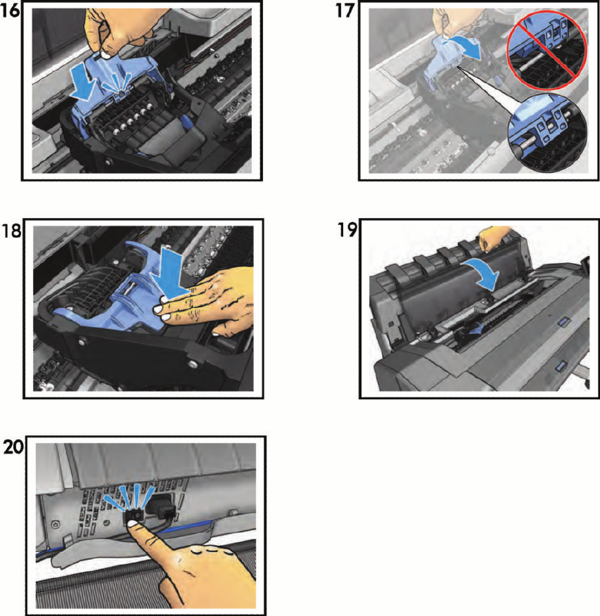
ENWW Carriage latch 493
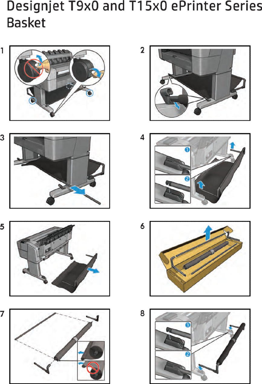
Basket
494 Chapter 8 Customer Self Repair Flyers ENWW
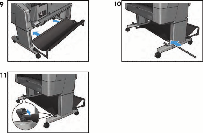
ENWW Basket 495
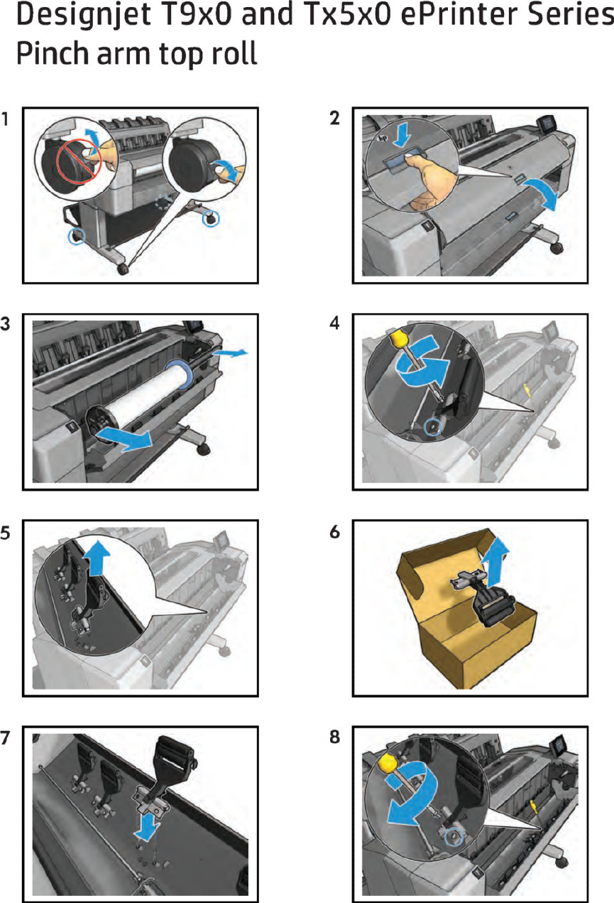
Pinch arm top roll
496 Chapter 8 Customer Self Repair Flyers ENWW
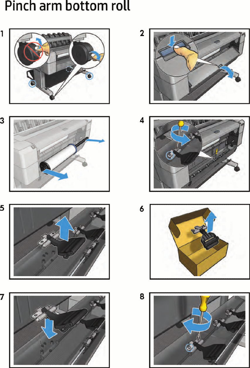
Pinch arm bottom roll
ENWW Pinch arm bottom roll 497
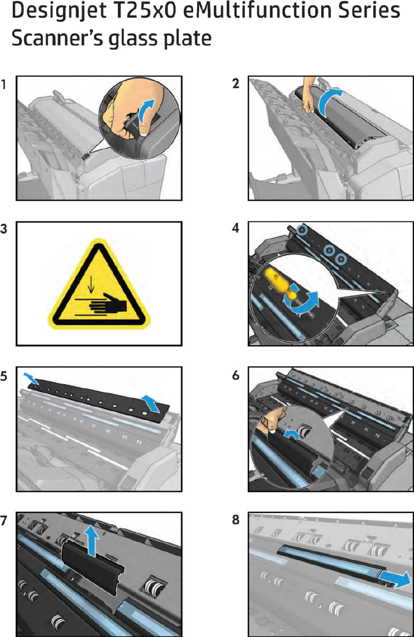
Scanner’s glass plate
498 Chapter 8 Customer Self Repair Flyers ENWW
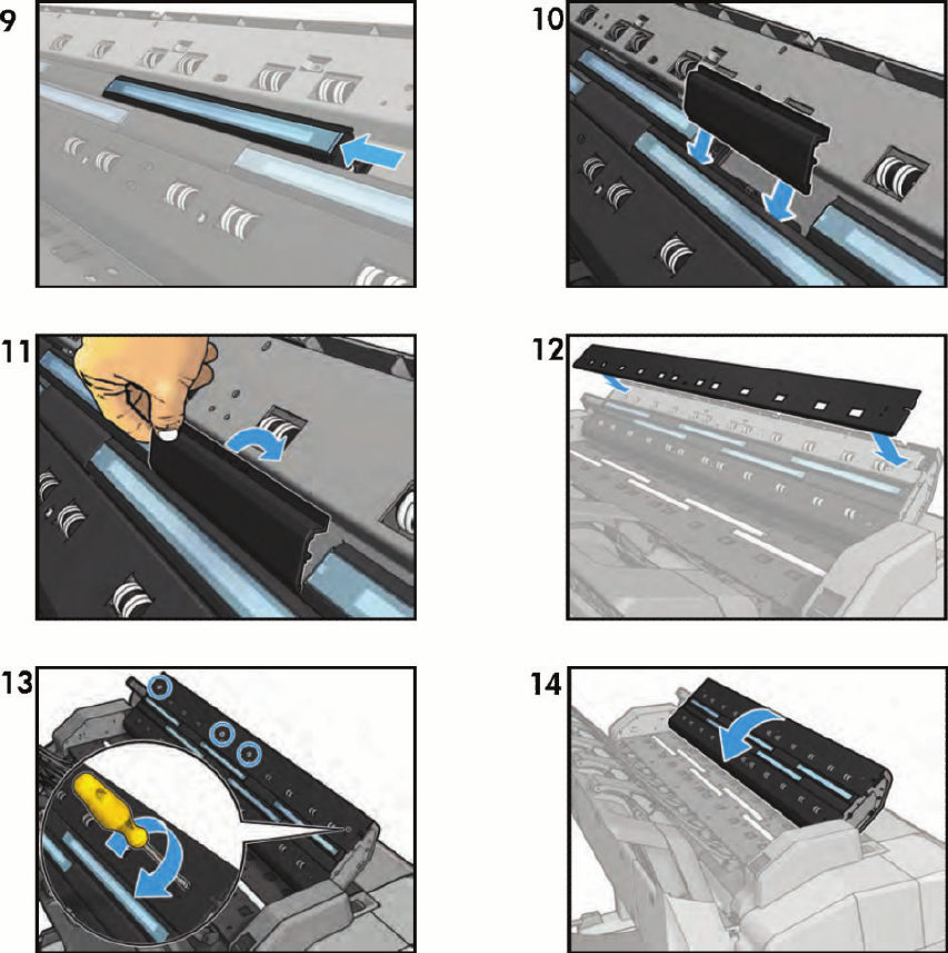
ENWW Scanner’s glass plate 499
