HP2011 HM Hinge Operated Safety Interlock Switch Instruction Sheet Manual En 201507 C369I E 01
2016-05-24
: Pdf Hp2011-Hm Manual En 201507 C369I-E-01 HP2011-HM_Manual_en_201507_C369I-E-01 Omron
Open the PDF directly: View PDF ![]() .
.
Page Count: 3
Correct use
Safety switch series HP2008-HM and HP2011-HM
(hinge switch with hollow shaft) are used in control
systems that perform safety functions, e.g. for
safety guards or as position encoders.
Before safety switches are used, a risk assessment
must be performed on the machine in accordance
with
EN 954-1, Safety of machinery. Safety related
parts of control systems. General principles for
design, Annex B
EN 1050, Safety of machinery. Principles for risk
assessment.
Correct use includes compliance with the relevant
requirements for installation and operation, in
particular
EN 954-1, Safety of machinery. Safety related
parts of control systems. General principles for
design
EN 1088, Safety of machinery. Interlocking
devices associated with guards. Principles for
design and selection
EN 60 204-1, Safety of machinery. Electrical
equipment of machines. General requirements.
Safety precautions
Safety switches perform a personal protection
function. Incorrect installation or tampering can
lead to severe injuries to personnel.
Safety switches must not be bypassed
(bridging of contacts), turned away, removed
or otherwise rendered ineffective.
General
The letters on the rating plate represent the product's
year of manufacture.
Function
The safety switch signals that the safety guard is
closed.
The switch does not perform guard locking!
Mounting
Mounting must be performed only by authorized
personnel.
Safety switches must be arranged such that they
are adequately secured against movement.
To meet these requirements:
The fixings must be reliable and must also require
the use of a tool to undo them.
Mount the safety switch positively
For safety-related applications (fixed positioning),
mount switch with M5x30 screws.
To ensure correct operation:
Axially align safety switch hollow shaft and hinged
actuator on the safety guard.
Positively connect hollow shaft to the moving part
of the safety guard (e.g. door).
Protection against environmental effects
A lasting and correct safety function requires that
the actuating head must be protected against the
penetration of foreign bodies such as dust, sand,
blasting shot, etc.
Cover the actuating head and the rating plate du-
ring painting work!
Only use solvent-free cleaning agents to clean the
safety switch!
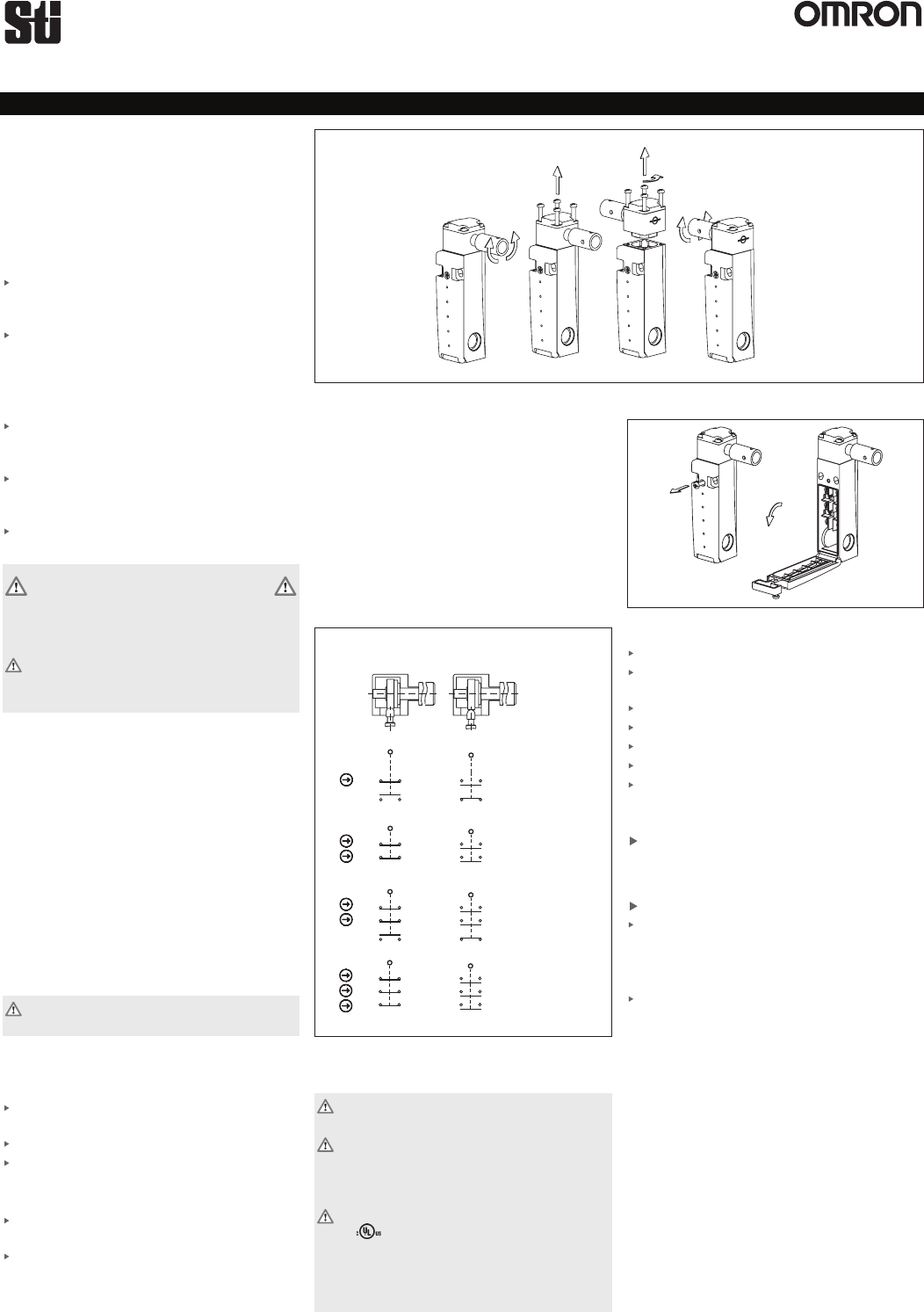
Switching elements and switching functions
Fig. 2: Switching elements and switching functions
Electrical connection
Electrical connection must be performed only
by authorized personnel.
When choosing the insulation material and wire
for the connections, pay attention to the over-
temperature in the housing (depending on the
operating conditions)!
For use and applications as per the requirements
of , a class 2 power supply or a class 2
transformer according to UL1310 or UL1585
must be used. As an alternative, a low voltage
power supply according to UL508 table 32.1
can be used.
Fig. 3: Opening the safety switch
Break out the required entry opening.
Fit cable gland M16 x 1.5, or NPT Adapter with
appropriate degree of protection.
Conductor cross-section 0.34 mm2 ... 1.5 mm².
For pin assignment see Figure 2.
Tighten the screws with a torque of 0.5 Nm.
Check that the cable entry is sealed.
Close the cover and screw in position.
Setup
Mechanical function test
Actuate hinged actuator and check the switching
function.
Electrical function test
Close the safety guard.
Start the machine.
Check whether the machine stops when the safety
guard is opened.
Switch off the machine.
Open the safety guard.
The machine must not start when the safety
guard is open (hinge switch actuated)!
Fig. 1: Changing the actuating direction
Torque=0,6Nm
A
ActuatedNot
actuated
13
21
31
11
21
31
31
21
13
21
14
22
32
12
22
32
32
22
14
22
31
21
13
31
21
11
21
31
21
13
32
22
14
32
22
12
22
32
22
14
HP-2011-021
HP2011-030
HP2008-11
HP2008-02
The safety switch HP2008-HM and HP2011-HM
comply with the regulations of EN 60947-5-1, Annex
K and comply with the requirements of the
employers’ liability insurance associations for
machines, installations and personnel protection.
HP2008-HM & HP2011-HM
Safety,
Technology
& Innovation
Operating Instructions for HP2008-HM and HP2011-HM Series Safety Switches
Rev. 1.08
Technical data
Parameters Value
Housing material Reinforced
thermoplastic
Degree of protection IP67
according to IEC 60529
Mech. operating cycles > 4x10 6
Ambient temperature -20...+80°C
Degree of contamination
(external, according 3 (industrial)
to EN 60947-1)
Installation position Any
Actuating force at 20 °C 0,1 Nm
Actuation frequency, max. 5000 / h
Switching principle Slow-action contact element
Contact material Silver alloy
gold flashed
Connection type Screw terminals
Conductor cross-section 0.34 mm2... 1.5 mm2
Rated impulse Uimp = 2.5 kV
withstand voltage
Rated Ui= 250 V
insulation voltage
Switching voltage min. 12 V
at 10 mA
Utilization category to EN 60947-5-1
V032A451-CA
V42A431-CD
Switching current, min., 1 mA
at 24 V
Short circuit protection
(control circuit fuse) 4 A gG
according to IEC 60269-1
Conventional thermal current I th 4 A
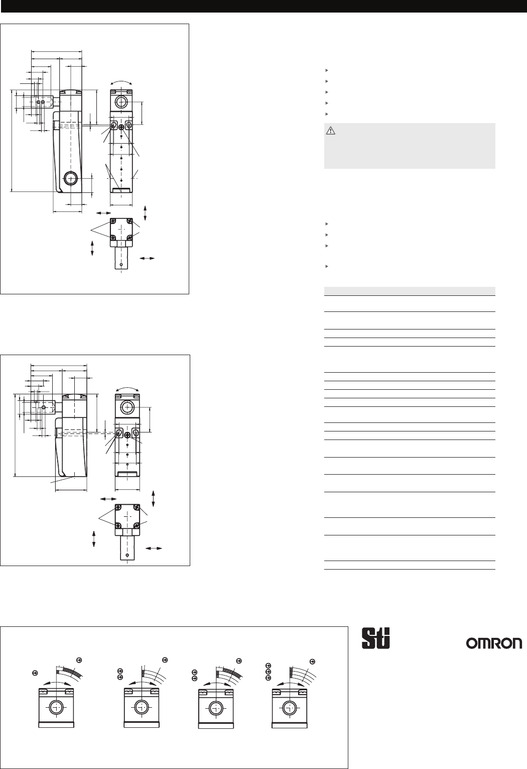
Fig. 8: Travel diagrams HP2008 and HP2011 Series Switches
Fig. 7: Dimension drawing for HP2008-HM
Fig. 6: Dimension drawing for HP2011-HM
Service and inspection
No servicing is required, but regular inspection
of the following is necessary to ensure trouble-free
long-term operation:
correct switching function
secure mounting of components
dirt and wear
sealing of cable entry
loose cable connections.
If damage or wear is found, the complete switch
must be replaced.
Replacement of individual parts or assemblies is
not permitted!
Safety switches must be completely replaced after 4
million operating cycles.
Exclusion of liability under the following
conditions:
if the unit is not used for its intended purpose
non-compliance with safety regulations
installation and electrical connection not
performed by authorized personnel.
failure to perform functional checks.
25
18
16,5
17
5
,
5
2
∅4,2
M16x1,5
M16x1,5
Torque=0,6Nm
*
∅5
5
,
1
0
4
(57)
8
13
22
3,2
3,2
M3
5
∅2
,
0
1
25
32
12,5
6
1
12,5
5
,
5
1
1
∅4
1
32
A
B
C
D
Torque=0,6Nm
Torque=0,6Nm
*fixed positioning
for safety-related
applications (M5)
5
,
1
25
18
16,5
17
,
5
25
∅4,2
Torque=0,6Nm
*
∅5
12,5
5
3,2
3,2
8
13
22
32
M3
∅2
,
0
1
25
0
4
5
,
5
8
∅4
1
32
(57)
M16x1,5
A
B
C
D
Torque=0,6Nm
Torque=0,6Nm
*fixed positioning
for safety-related
applications (M5)
HP2008-11
21-22
13-14
0°
10°
4°
25°
HP2008-02
31-32
21-22
0°
4°
25°
HP2011-021
31-32
21-22
13-14
0°
10°
4°
25°
HP2011-030
0°
11-12
21-22
31-32
25°
4°
HP2008-HM & HP2011-HM
Operating Instructions for HP2008-HM and HP2011-HM Series Safety Switches
OMRON SCIENTIFIC TECHNOLOGIES, INC.
6550 Dumbarton Circle, Fremont CA 94555-3605 USA
Tel: 1/510/608-3400
Fax: 1/510/744-1442
E-mail: sales@sti.com
www.sti.com
UK Sales Office
Tel: +44 (0) 1395-273-209
Fax: +44 (0) 1395-276-183
European Tech Support
Tel: +49 (0) 52 58 93 87 76
Fax: +49 (0) 52 58 93 56 90
©2007 Omron Scientific Technologies, Inc. All rights reserved.
Subject to technical modifications.
Drawing number 097122-02-09/07
Safety,
Technology
& Innovation

OMRON CANADA, INC. • HEAD OFFICE
Toronto, ON, Canada • 416.286.6465 • 866.986.6766 • www.omron247.com
OMRON ELECTRONICS DE MEXICO • HEAD OFFICE
México DF • 52.
55.59.01.43.00
• 01-800-226-6766 • mela@omron.com
OMRON ELECTRONICS DE MEXICO • SALES OFFICE
Apodaca, N.L. • 52.81.11.56.99.20 • 01-800-226-6766 • mela@omron.com
OMRON ELETRÔNICA DO BRASIL LTDA • HEAD OFFICE
São Paulo, SP, Brasil • 55.11.2101.6300 • www.omron.com.br
OMRON ARGENTINA • SALES OFFICE
Cono Sur • 54.11.4783.5300
OMRON CHILE • SALES OFFICE
Santiago • 56.9.9917.3920
OTHER OMRON LATIN AMERICA SALES
54.11.4783.5300
Authorized Distributor:
C369I-E-01 07/15
Note: Specifications are subject to change. © 2015 Omron Electronics LLC Printed in U.S.A.
Printed on recycled paper.
Automation Control Systems
• Machine Automation Controllers (MAC) • Programmable Controllers (PLC)
• Operator interfaces (HMI) • Distributed I/O • Software
Drives & Motion Controls
• Servo & AC Drives • Motion Controllers & Encoders
Temperature & Process Controllers
• Single and Multi-loop Controllers
Sensors & Vision
• Proximity Sensors • Photoelectric Sensors • Fiber-Optic Sensors
• Amplified Photomicrosensors • Measurement Sensors
• Ultrasonic Sensors • Vision Sensors
Industrial Components
• RFID/Code Readers • Relays • Pushbuttons & Indicators
• Limit and Basic Switches • Timers • Counters • Metering Devices
• Power Supplies
Safety
• Laser Scanners • Safety Mats • Edges and Bumpers • Programmable Safety
Controllers • Light Curtains • Safety Relays • Safety Interlock Switches
OMRON AUTOMATION AND SAFETY • THE AMERICAS HEADQUARTERS • Chicago, IL USA • 847.843.7900 • 800.556.6766 • www.omron247.com
OMRON EUROPE B.V. •
Wegalaan 67-69, NL-2132 JD, Hoofddorp, The Netherlands.
•
+31 (0) 23 568 13 00
•
www.industrial.omron.eu
