LC 3 Instructions
User Manual: Pdf
Open the PDF directly: View PDF ![]() .
.
Page Count: 16

LC-3 Instructions Page 1 of 16
LC-3 Instruction Summary
15 14 13 12 11 10 9 8 7 6 5 4 3 2 1 0
ADD
*
0001 DR SR1 0 0 0 SR2
ADD
*
0001 DR SR1 1 imm5
AND
*
0101 DR SR1 0 0 0 SR2
AND
*
0101 DR SR1 1 imm5
BR 0000 n z p PCoffset9
JMP 1100 0 0 0 BaseR 0 0 0 0 0 0
JSR 0100 1 PCoffset11
JSRR 0100 0 0 0 BaseR 0 0 0 0 0 0
LD
*
0010 DR PCoffset9
LDI
*
1010 DR PCoffset9
LDR
*
0110 DR BaseR offset6
LEA
*
1110 DR PCoffset9
NOT
*
1001 DR SR 1 1 1 1 1 1
RET 1100 0 0 0 1 1 1 0 0 0 0 0 0
RTI 1000 0 0 0 0 0 0 0 0 0 0 0 0
ST 0011 SR PCoffset9
STI 1011 SR PCoffset9
STR 0111 SR BaseR offset6
TRAP 1111 0 0 0 0 trapvect8
x20 = GetC
x21 = Out
x22 = PutS
x23 = In
x25 = Halt
Note: * indicates instructions that modify the condition codes (CC).

LC-3 Instructions Page 2 of 16
Instruction Assembler Format Example Operation
Addition
ADD
ADD dr, sr1, sr2
ADD dr, sr1, imm5
ADD R2, R3, R4
ADD R2, R3, #7
R2
←
R3 + R4
R2 ← R3 + 7
Logical AND
AND
AND dr, sr1, sr2
AND dr, sr1, imm5
AND R2, R3, R4
AND R2, R3, #7
R2
←
R3 AND R4
R2 ← R3 AND 7
Conditional Branch BR label
BRn label
BRz label
BRp label
BRnz label
BRnp label
BRzp label
BRnzp label
BRnz loop
BRnzp loop
Unconditional branch
Branch if the CC is negative or
zero.
Unconditional branch
Jump
JMP
JMP baseR
JMP foo Jump to foo.
PC ← baseR
Jump to Subroutine
JSR / JSRR
JSR PCoffset11
JSRR baseR
JSR Sort
JSRR R2
R7
←
PC+1
Jump to Sort
R7 ← PC+1
Jump to address in R2
Load Direct
LD
LD dr, label LD R4, count R4
←
mem[count]
Load Indirect
LDI
LDI dr, label LDI R4, pointer R4
←
mem[mem[pointer]]
Load Base + Offset
LDR
LDR dr, baseR, offset6 LDR R4, R2, #10 R4
←
contents of mem[R2+#10]
Load Effective
Address
LEA
LEA dr, label LEA R4, foo R4
←
address of foo
Complement
NOT
NOT dr, sr NOT R4, R2 R4
←
NOT(R2)
Return from
Subroutine
RET
RET RET PC
←
R7
Return from Interrupt
RTI
RTI RTI NZP, PC
←
top two values
popped off stack
Store Direct
ST
ST sr, label ST R4, count mem[count]
←
R4
Store Indirect
STI
STI SR, label STI R4, pointer mem[mem[pointer]] ← R4

LC-3 Instructions Page 3 of 16
Store Base + Offset
STR
STR sr, baseR, offset6 STR R4, R2, #10 mem[R2+#10] ← R4
Operating System Call
TRAP
TRAP x20
TRAP x21
TRAP x22
TRAP x23
TRAP x25
GETC
OUT
PUTS
IN
HALT
Get a character from keyboard.
The character is not echoed
onto the screen. Its ASCII code
is copied into R0. The high
eight bits of R0 are cleared.
Write a character in R0[7:0] to
the screen
Write a string pointed to by R0
to the screen.
Print a prompt on the screen and
read a single character from
the keyboard. The character is
echoed onto the screen, and its
ASCII code is copied into R0.
The high eight bits of R0 are
cleared.
Halt execution
General purpose registers:
The LC-3 has eight 16-bit general purpose registers R0 to R7.
Special memory locations:
xF3FC CRT status register (CRTSR). The ready bit (bit 15) indicates if the video device is ready to
receive another character to print on the screen.
xF3FF CRT data register (CRTDR). A character written in the low byte of this register will be displayed
on the screen.
xF400 Keyboard status register (KBSR). The ready bit (bit 15) indicates if the keyboard has received a
new character.
xF401 Keyboard data register (KBDR). Bits [7:0] contain the last character typed on the keyboard.
xF402 Machine control register (MCR). Bit [15] is the clock enable bit. When cleared, instruction
processing stops.
Notations:
baseR – base register
dr – destination register
imm5 – a five-bit immediate value
mem[address] – denotes the contents of memory at the given address
PCoffset9 – a 9-bit immediate value used in an offset relative to the incremented PC
offset6 – a 6-bit immediate value used in a Base+Offset instruction
sr – source register
CC – condition code register (N,Z,P)
LC-3 Instructions Page 4 of 16
1. Operate instructions
ADD
15 14 13 12 11 10 9 8 7 6 5 4 3 2 1 0
0 0 0 1 DR SR1 0 0 0 SR2
0 0 0 1 DR SR1 1 imm5
if (bit[5] == 0)
DR = SR1 + SR2
else
DR = SR1 + sign-extend(imm5)
set cc(DR)
Example:
ADD R2, R3, R4 ; R2 ← R3 + R4
ADD R2, R3, #7 ; R2 ← R3 + 7
AND
15 14 13 12 11 10 9 8 7 6 5 4 3 2 1 0
0 1 0 1 DR SR1 0 0 0 SR2
0 1 0 1 DR SR1 1 imm5
if (bit[5] == 0)
DR = SR1 AND SR2
else
DR = SR1 AND sign-extend(imm5)
set cc(DR)
NOT
15 14 13 12 11 10 9 8 7 6 5 4 3 2 1 0
1 0 0 1 DR SR 1 1 1 1 1 1
There is no OR instruction. However, using DeMorgan’s law A OR B is:
A OR B = (A' AND B' )'

LC-3 Instructions Page 5 of 16
2. Data movement instructions
Load and Store
Format
15 14 13 12 11 10 9 8 7 6 5 4 3 2 1 0
opcode DR or SR operand specifier
The load and store instructions are for copying data between a register and a memory location. The
load instruction copies data from a memory location to a register, whereas, the store instruction copies
data from a register to a memory location.
There are four different versions of the load and store instructions. They differ in how the address of
the memory location to be accessed is calculated. This is referred to as the different addressing modes of
the instruction.
Addressing Modes
Address modes specify how the memory address is calculated.
LC-3 Instructions Page 6 of 16
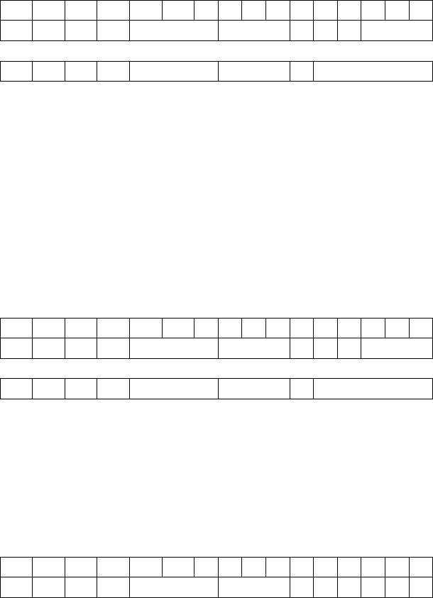
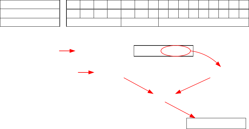
PC-Relative Addressing Mode
LD (0010) and ST (0011) specify the PC-relative addressing mode. It loads (LD) or stores (ST) the value
that is found in the memory address that is formed by sign-extending bits [8:0] to 16 bits and adding this
value to the incremented PC. The content in memory at this address is loaded into DR for the LD
instruction. For the ST instruction, the content of the SR is stored into the memory at this computed
address.
memory address 15 14 13 12 11 10 9 8 7 6 5 4 3 2 1 0
x4018 0 0 1 0 1 0 1 1 1 0 1 0 1 1 1 1
LD DR or SR PCoffset9
The PC is x4018. The incremented PC, i.e. PC+1, is x4019. The 9-bit offset in the instruction x1AF is
sign-extended to 16 bits giving FFAF. The incremented PC (x4019) is added to the sign-extended offset
(xFFAF) giving x3FC8. For the LD instruction, the value in memory location x3FC8 is loaded into
register R5. For the ST instruction, the value in R5 is stored into memory location x3FC8.
1010 1010 1010 1010
0010 101 1101011110100 0000 0001 1000
Memory Address Memory Content
0011 1111 1100 1000 1010 1010 1010 1010
R5
LD
ST
1111 1111 1010 1111PC+1 0100 0000 0001 1001
PC sign extend to 16 bits
+
0011 1111 1100 1000
Memory Address Memory Content
Example
LD R5, offset ; R5 ← mem[PC+1+SEXT(offset)]
ST R5, offset ; mem[PC+1+SEXT(offset)] ← R5
LC-3 Instructions Page 7 of 16
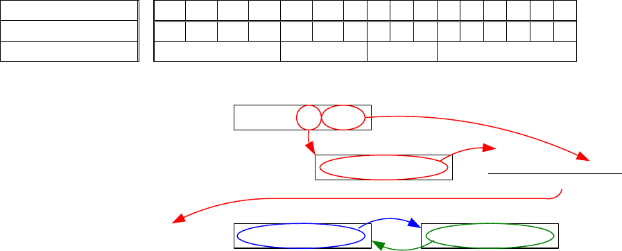
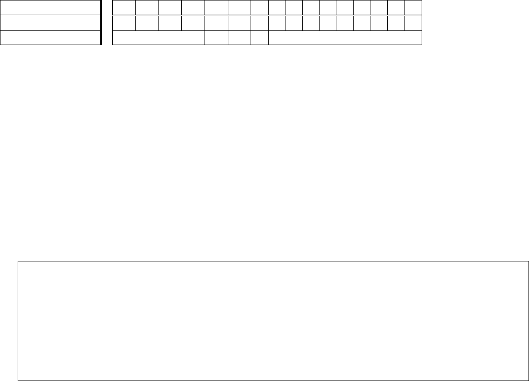
Base+Offset Addressing Mode
LDR (0110) and STR (0111) specify the base+offset addressing mode. The address of the operand is
obtained by adding the sign-extended 6-bit offset to the content of the specified base register. The result is
the effective address of the memory location to be accessed.
memory address 15 14 13 12 11 10 9 8 7 6 5 4 3 2 1 0
x4018 0 1 1 0 1 0 1 1 1 1 0 1 1 1 0 1
LDR DR or SR BaseR Offset6
1111 0000 1111 00001111 0000 1111 0000
0110 101 111 0111010100 0000 0001 1000
Memory Address Memory Content
0010 0011 0110 0010
0010 0011 0100 0101
R7
LDR
STR
0010 0011 0100 0101
+ 0000 0000 0001 1101
0010 0011 0110 0010
R5
Example
LDR R5, R7, offset ;R5 ← mem[R7 + SEXT(offset)]
STR R5, R7, offset ;mem[R7 + SEXT(offset)] ← R5
LC-3 Instructions Page 8 of 16
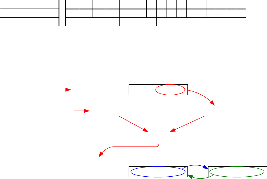
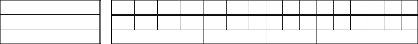
Indirect Addressing Mode
LDI (1010) and ST I(1011) specify the indirect addressing mode. An address is first formed like the LD
and ST instructions. However, the contents from this memory location form the address of the operand to
be loaded or stored.
memory address 15 14 13 12 11 10 9 8 7 6 5 4 3 2 1 0
x4018 1 0 1 0 1 0 1 1 1 0 1 0 1 1 1 1
LDI DR or SR PCoffset9
0011 1101 1001 1001
1010 101 1101011110100 0000 0001 1000
Memory Address Memory Content
0011 1111 1100 1000
1111 1111 1010 1111PC+1 0100 0000 0001 1001
PC sign extend to 16 bits
+
0011 1111 1100 1000
Memory Address Memory Content
1010 1010 1010 10100011 1101 1001 1001 1010 1010 1010 1010
R5
LDI
STI
Memory Address Memory Content
Example
LDI R5, offset ; R5 ← mem[mem[PC+1+SEXT(offset)]]
STI R5, offset ; mem[mem[PC+1+SEXT(offset)]] ← R5
LC-3 Instructions Page 9 of 16
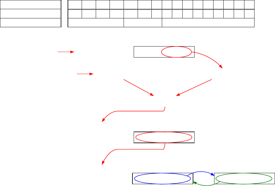
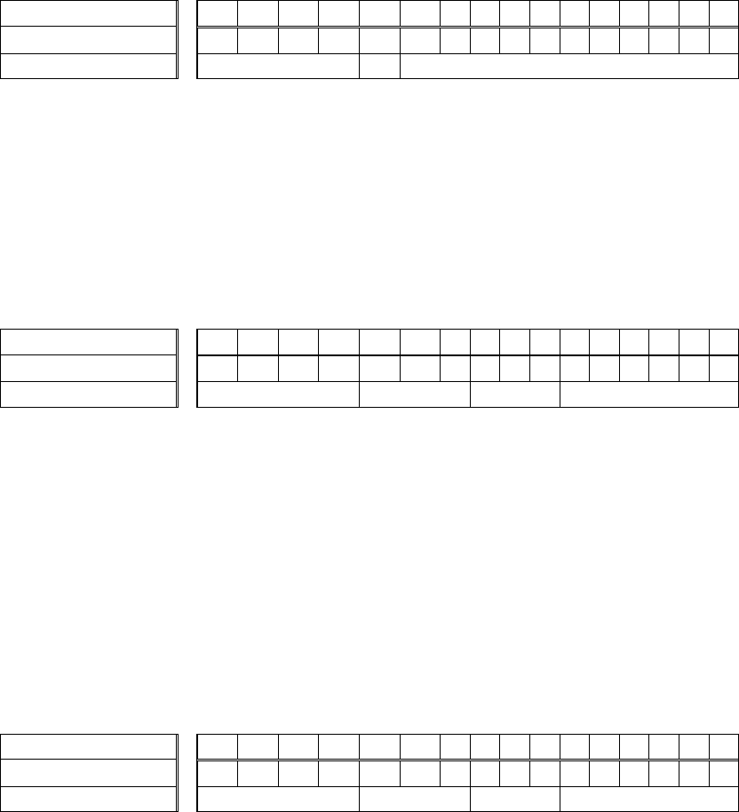
Immediate Addressing Mode
The LEA (1110) instruction loads the immediate value formed by adding the incremented PC to the sign-
extended 9-bit offset.
memory address 15 14 13 12 11 10 9 8 7 6 5 4 3 2 1 0
x4018 1 1 1 0 1 0 1 1 1 0 1 0 1 1 1 1
LEA DR PCoffset9
0010 101 1101011110100 0000 0001 1000
Memory Address Memory Content
0011 1111 1100 1000
R5
1111 1111 1010 1111PC+1 0100 0000 0001 1001
PC sign extend to 16 bits
+
0011 1111 1100 1000
Example
LEA R5, offset ; R5 ← PC+1+SEXT(offset)
LC-3 Instructions Page 10 of 16
3. Control Instructions
Branch
The conditional branch BR (0000) instruction format is
memory address 15 14 13 12 11 10 9 8 7 6 5 4 3 2 1 0
x4C18 0 0 0 0 0 1 1 1 1 1 1 1 1 1 0 1
BR N Z P PCoffset9
When a condition bit [11:9] (N, Z, P) is set, that corresponding condition code is checked. If that
corresponding condition is set (i.e. true), then the PC is loaded with the value formed by adding the
incremented PC to the sign-extended 9-bit offset [8:0].
All instructions that write values into registers set the three condition code registers (i.e., the single-bit
registers N, Z, P) depending on whether the value written is negative, zero, or positive. These instructions
are ADD, AND, NOT, LD, LDI, LDR, and LEA.
BR Label BRnz Label
BRn Label BRnp Label
BRz Label BRzp Label
BRp Label BRnzp Label (unconditional jump)
; loop 10 times
3000 AND R0,R0,#0
ADD R0,R0,#10
; beginning of loop
NOP
ADD R0,R0,#-1 ; decrement by 1
BRp #-3 ; loop back if positive
LC-3 Instructions Page 11 of 16
JMP
The unconditional jump JMP (1100) instruction format is
memory address 15 14 13 12 11 10 9 8 7 6 5 4 3 2 1 0
x4018 1 1 0 0 0 0 0 1 1 1 0 0 0 0 0 0
JMP BaseR
Unconditionally jumps to the location specified by the contents of the base register.
Loads the PC with the value in the BaseR.
LC-3 Instructions Page 12 of 16
JSR (Jump Subroutine)
The Jump Subroutine instruction is used to implement function calls.
The JSR (0100) instruction format is
memory address 15 14 13 12 11 10 9 8 7 6 5 4 3 2 1 0
x4018 0 1 0 0 1 0 0 1 1 1 0 1 1 1 0 1
JSR PCoffset11
Bit 11 for the JSR instruction is a 1.
Save the incremented PC in R7; This is used to return from subroutine
Loads the PC with the value formed by adding the incremented PC to the sign-extended 11-bit offset
[10:0].
JSRR (Jump Subroutine Register)
The JSRR (0100) instruction format is
memory address 15 14 13 12 11 10 9 8 7 6 5 4 3 2 1 0
x4018 0 1 0 0 0 0 0 1 1 1 0 0 0 0 0 0
JSRR BaseR
Bit 11 for the JSRR instruction is a 0.
Save the incremented PC in R7; This is used to return from subroutine
Loads the PC with the contents of the base register.
RET (Return)
The Return instruction is used to return from a function to the caller.
It simply copies R7 to the PC.
It is the same as JMP R7
memory address 15 14 13 12 11 10 9 8 7 6 5 4 3 2 1 0
x4018 1 1 0 0 0 0 0 1 1 1 0 0 0 0 0 0
JMP BaseR

LC-3 Instructions Page 13 of 16
Trap
The Trap (1111) instruction invokes a system routine. When the OS is finished performing the service
call, the program counter is set to the address of the instruction following the TRAP instruction and the
program continues.
15 14 13 12 11 10 9 8 7 6 5 4 3 2 1 0
1 1 1 1 0 0 0 0 0 0 1 0 0 0 1 1
TRAP trap vector
R7 ← PC;
PC ← mem[ZEXT(trapvector8)
Trap Number Assembler Name Description
x20 GETC Read a single character from the keyboard. The
character is not echoed onto the console. Its ASCII
code is copied into R0. The high eight bits of R0 are
cleared.
x21 OUT Write a character in R0[7:0] to the console.
x22 PUTS Write a string pointed to by R0 to the console.
x23 IN Print a prompt on the screen and read a single
character from the keyboard. The character is echoed
onto the console, and its ASCII code is copied into
R0. The high eight bits of R0 are cleared.
x25 HALT Halt execution and print a message on the console.

LC-3 Instructions Page 14 of 16
Compiler Directives
• Commands to tell the assembler what to do. These are not LC3 commands.
• All directives start with a period (.).
Directive Description Example
.ORIG Where to start placing code in memory .ORIG $3000
.FILL Allocate one memory location and initialize it
with a value.
.FILL x30
.BLKW Allocate a block of memory (array). .BLKW #5
.STRINGZ Allocate and initialize memory with a null
terminated string.
.STRINGZ “Hello World”
.END Tells assembler the end of your source listing .END
Examples
.ORIG $3000
Thirty .FILL x30 ; allocate a memory location, initialize it to x30, and label it
Array .BLKW 20 #0 ; allocate 20 locations and initialize them all to zero.
; the starting location is labeled “Array”
Hi .STRINGZ “Hello World” ; allocate and initialize memory with the string “Hello World”
.END

LC-3 Instructions Page 15 of 16
Examples
; Print Hello World on the console
.ORIG x3000
LEA R0, Hi
PUTS
HALT
Hi .STRINGZ "Hello World"
.END
; Output the numbers from 0 to 9 to the console
.ORIG x3000
LD R3,Thirty ; R3 = x30
AND R1,R1,#0 ; R1 = 0
Loop ADD R0,R1,#-10 ; subtract 10 to test for the ending condition
BRz Stop
ADD R0,R1,R3 ; convert R1 to ASCII
OUT
ADD R1,R1,#1
BR Loop
Stop HALT
Thirty .FILL x30
.END
Exercises
Write LC-3 assembly programs for the following:
1) Output the numbers from 0 to 9 with one number per line. Hint: Use carriage return (CR).
2) Use .FILL to put two numbers in the range 0 to 4 in memory. Write a program to calculate and
output the sum of these two numbers on the console.
3) Use .FILL to put a two-digit decimal number in memory. Print out this number on the console.
4) Output the numbers from 0 to 19.
5) Same as 2) but the two numbers are in the range 0 to 9.
6) Use .FILL to put ten numbers in memory. Write a program to print out the largest of these ten
numbers.

LC-3 Instructions Page 16 of 16
; input two one-digit numbers and print out the sum.
; Correct only if the sum is less than 10
.ORIG x3000
LD R3,nThirty ; load constant x-30
LEA R0,Prompt ; print prompt to enter number
PUTS
GETC ; get first number
OUT ; echo it
ADD R0,R0,R3 ; convert ASCII to value
ADD R1,R0,#0 ; save first number in R1
LD R0,CR ; print Return
OUT
LEA R0,Prompt ; print prompt to enter number
PUTS
GETC ; get second number
OUT ; echo it
ADD R0,R0,R3 ; convert ASCII to value
ADD R2,R0,#0 ; save second number in R2
ADD R2,R1,R2 ; add R2 <- R1+R2
LD R0,CR ; print Return
OUT
LEA R0,Sum
PUTS
JSR Convert ; call function to convert number to ASCII
OUT
HALT ; end of main program
;;;;;;;;;;;;;;;;;;;;;;;;;;;;;;;;;;;;;;;;;;;
; subroutine to convert number in R2 to ASCII
; need to add x30
Convert
LD R0,Thirty
ADD R0,R2,R0 ;
RET
;;;;;;;;;;;;;;;;;;;;;;;;;;;;;;;;;;;;;;;;;;;
; start of constants
nThirty.FILL x-30
Thirty .FILL x30
CR .FILL x0D
Prompt .STRINGZ "Enter a number? "
Sum .STRINGZ "The sum is "
.END
