T800/TA087/M087 02 001 M087
T800/TA087/M087-02-001 M087-02-001
T800/TA087/M087-02-001 M087-02-001
T800/TA087/M087-02-001 M087-02-001
User Manual: Pdf T800/TA087/M087-02-001
Open the PDF directly: View PDF ![]() .
.
Page Count: 31
- TA087-02-0000 Speaker and Channel Change
- 1 Introduction
- 2 Specifications
- 3 Circuit Description
- 4 PCB Information
- 5 Cable and Connector Specifications
- 6 Installation
- 7 Operation
- 8 Programming
- 9 Fault Finding
- 10 IC Data Sheets
M087-02-001
Copyright TEL 27/07/00
M087-02-001, Issue 001 July 2000
TA087-02-0000 Speaker and
Channel Change Switch
Service Manual

M087-02-001
27/07/00 Copyright TEL
About This Manual
Scope This manual contains general, technical and servicing information
about the TA087-02-0000.
Errors If you find an error in this manual, or have a suggestion on how it
might be improved, please do not hesitate to contact the Technical
Writer, Custom Solutions Development, Tait Radio System’s Division,
Tait Electronics Ltd, P.O. Box 1645, Christchurch, New Zealand.
Technical Information
Any enquiries regarding this manual or the equipment it describes should be addressed in the first
instance to Custom Solutions Development, Tait Radio Systems Division, Tait Electronics Ltd,
P.O. Box 1645, Christchurch, New Zealand.
Updating Equipment and Manuals
In the interests of improving performance, reliability or servicing, Tait Electronics Ltd reserve
the right to update their equipment and/or manuals without prior notice.
Copyright
All information contained in this manual is the property of Tait Electronics Ltd. All rights are
reserved. This manual may not, in whole or part, be copied, photocopied, reproduced, translated
stored or reduced to any electronic medium or machine readable form without prior written per-
mission from Tait Electronics Ltd.
Ordering Tait Service Manuals
Service Manuals should be ordered from your nearest Tait Branch or approved Dealer. When
ordering, quote the Tait product code and, where applicable, the version.
Date Of Issue
M087-02-001 Speaker and Channel Switch
Issue 001 published July 2000

M087-02-001
Introduction
1
Copyright TEL 27/07/00
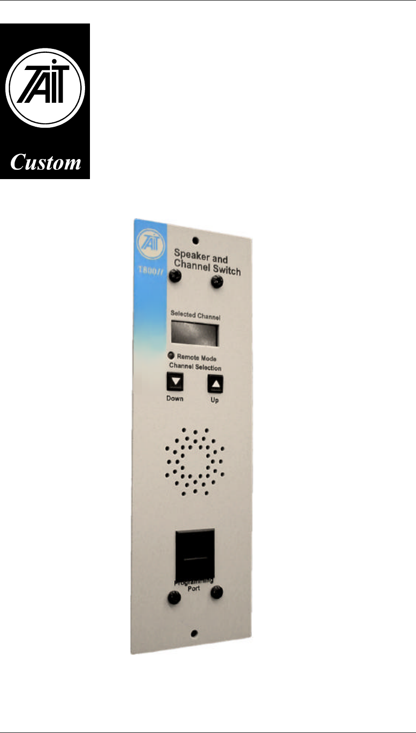
1 Introduction
The TA0087-02-000 Speaker and Channel Switch is a channel change module for T800
Series II Base Stations. It replaces the TA087-01, which was designed to suit the T800
Series I Base Stations. The module requires the T800-08 programmable lead for
programming.
The TA0087-02-000 module has the following features:
■Mounts in a standard T800 Series II rack
■Replaces the standard speaker and programming module
■Provides up to 256 programmable channel data entries - 99 for BCD coded
entries
■Provides a simple channel change interface with auto-repeating UP/DOWN
keys
■Provides opto coupled connection for remote control buttons
■Provides a clear 3 digit 7 segment LED display
■Provides an output connector for changing channels for other modules
■Provides a remote connector for selecting an index value of channel data
blocks
■Provides an indication LED for REMOTE mode (See Sec 3.4.2)
■Provides auto revert from local mode
■Contains a unique serial number
■Provides an optional RS232C port for serial channel data output
■Provides a database and programming software
■Provides easy integration to T800 programming software
■Provides Binary or BCD mode, selectable during programming
■Provides programmable input logic: positive or negative

2
Specifications
M087-02-001
27/07/00 Copyright TEL
2 Specifications
Supply 10.8 - 16V
Micro controller 68HC705C8
Dimensions 183 x 59 x 24mm
Weight 250gm
Environment temperature range: -30 to +60C
humidity: 95%
Modes local or remote
No. of channels Binary : 256
BCD : 99
External up down inputs opto coupled with current limitation
Display 3 digit 7 segment display
Programming T800 ping-pong protocol
Optional RS232 via 9 way D-socket

M087-02-001
Circuit Description
3
Copyright TEL 27/07/00
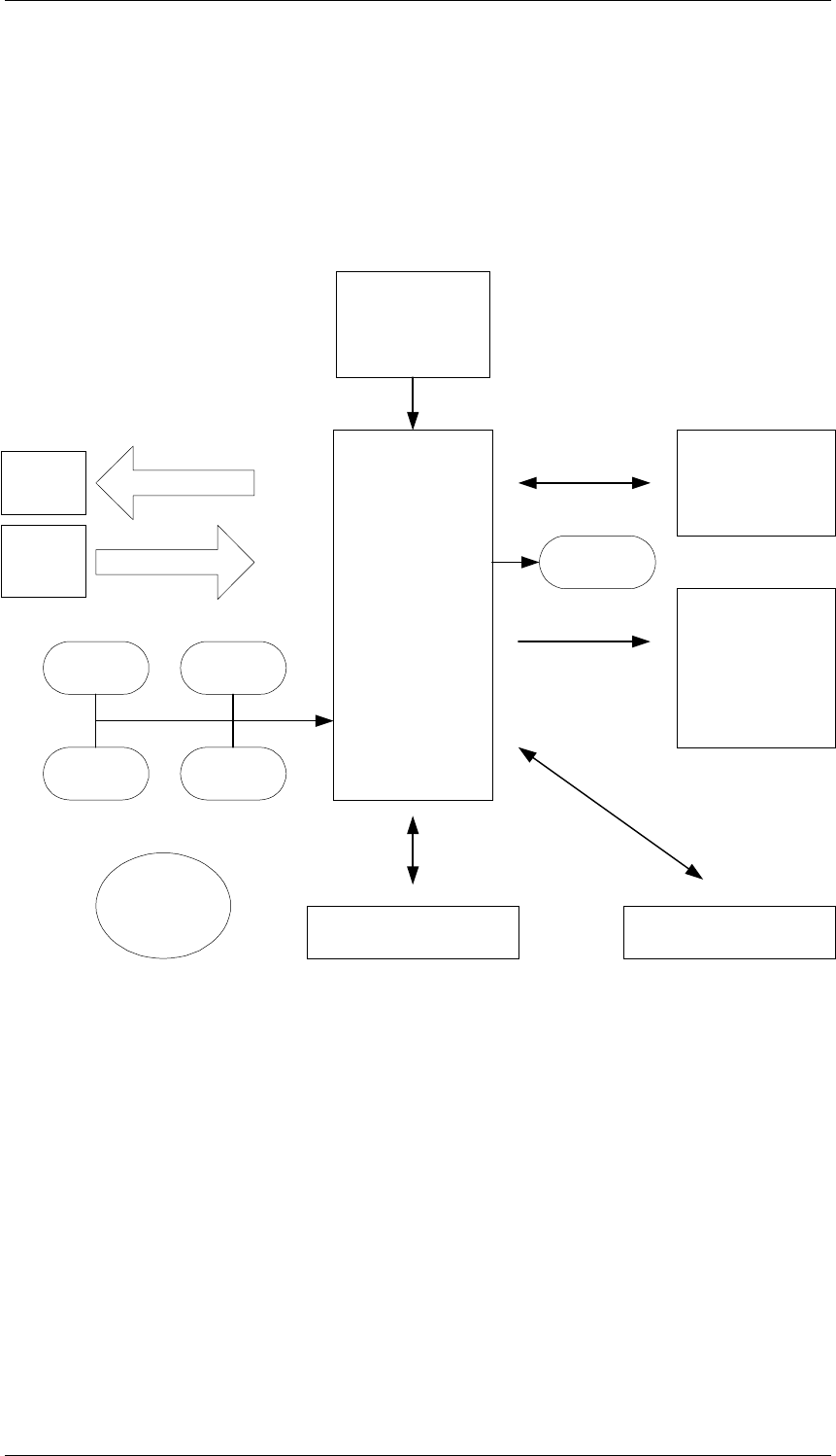
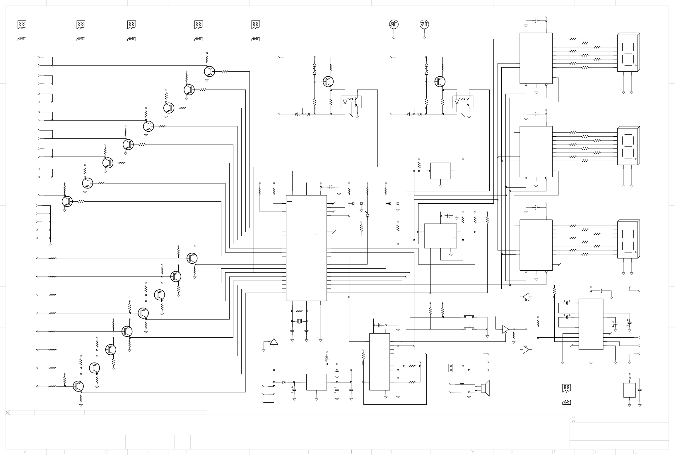
3 Circuit Description
A 68HC705C8 microprocessor provides the required reading and writing of all I/O
lines.
8 Logic outputs are generated from Port A of the micro to select the T800 module
channels. The signals are available on D Range SK1. A loom to interface to the T800 rack
panel comes as standard with the TA087-02-0000.
In remote mode, the processor reads the external inputs via Port B. Inputs can be active
high or active low, depending the programming of the TA087-02-0000. A 9 way D-range
socket provides easy access. The input ports are protected against positive and negative
over voltage.
The serial I/O ports of the processor are used to communicate with the EEprom and to
write to the output registers for the 7 segment displays.
Programming Circuit
Programming takes place via the T800-08 programming cable. This cable limits the
RS232 voltages to 5V. The processor in the TA087-02-0000 keeps IC10 (4053 analog
switch) in Inhibit mode. An incoming data packet - 9600 baud, 1 stop and start bit - will
generate an interrupt on pin 2 (IRQ) of the microprocessor. The processor will respond
by changing the inhibit line on IC10 to +5V.
The same line puts an inhibit on the RS232 output into the micro. Control inputs A and
B of IC10 are set high. This prevents R70 and R71 loading R62. Control input C, toggled
by the incoming serial data packet, switches output Z between 0 and +5V via Z0 and Z1.
The resulting signal constitutes the “ping” or RXD to the microprocessor. When the
message is finished the serial comms line goes high impedance. The PC is now waiting
for a response.
If the data packet contains the correct coding for the unit its processor responds with
“pong” by toggling control lines A and B of IC10. The resulting signal at X and Y of IC10
forms the TXD signal.
At the end of the exchange the microprocessor reverts the inhibit line on IC 10 to high
re-establishing communications between the microprocessor and the RS232 chip.
PC
RS232C
PORT
CPU
UART
PORT
TXD
RXD
TXD
RXD
4
Circuit Description
M087-02-001
27/07/00 Copyright TEL
Up-down channel control
The up down buttons on the front panel are directly connected to two ports on the
microprocessor. The opto couplers are connected in parallel with these two buttons and
will go low when a current of at least 7mA flows through the input diode. Operation of
the opto coupler is typically between +12V and a switch to Gnd.
Low voltage protection
A Low Voltage detector has been included in the unit to ensure proper shut down of the
microprocessor to protect the database in the EEprom. When the +5V supply drops
below 4.75V the output of IC9 switches to Gnd, providing reset to the micro and to the
shift registers of the LED displays.
CPU
68HC705C8A
Output Channel data 4K bits
EEPROM
Input Channel data
PingPong Circuit Optional RS232C circuit
Power and Reset
Shift Registers
and
3 Digit
7 SEG LED
CH_UP
KEY CH_DN
KEY
OPTO_UP
KEY OPTO_DN
KEY
SPEAKER
Output
Connector
Remote
Connector REMOTE_LED

M087-02-001
PCB Information
5
Copyright TEL 27/07/00
4 PCB Information
SMD Parts
Ref IPN Description
C1 015-26100-08 CAP 100N 10% 50V X7R
C2 015-26100-08 CAP 100N 10% 50V X7R
C5 015-26100-08 CAP 100N 10% 50V X7R
C6 015-26100-08 CAP 100N 10% 50V X7R
C7 015-26100-08 CAP 100N 10% 50V X7R
C8 015-26100-08 CAP 100N 10% 50V X7R
C10 015-26100-08 CAP 100N 10% 50V X7R
*C11 015-26100-08 CAP 100N 10% 50V X7R
C20 016-08470-01 CAP 47U ELEC 16V 6.6*7.3MM SMD
C21 015-22390-01 CAP 39P 5% NPO 50V
C22 015-22390-01 CAP 39P 5% NPO 50V
C23 016-08470-01 CAP 47U ELEC 16V 6.6*7.3MM SMD
C25 015-26100-08 CAP 100N 10% 50V X7R
D1 001-10000-56 DIODE BAW56 DUAL SWITCH COMMON
ANODE
D2 001-10000-99 DIODE BAV99 DUAL SW (PIN 3 IS
ANODE/CATH)
D3 001-10000-56 DIODE BAW56 DUAL SWITCH COMMON
ANODE
D4 001-10000-99 DIODE BAV99 DUAL SW (PIN 3 IS
ANODE/CATH)
D13 001-10000-99 DIODE BAV99 DUAL SW (PIN 3 IS
ANODE/CATH)
D16 001-10011-74 DIODE MRA4004T3 PWR RECTIFIER
400V 1A CASE
IC1 240-04020-42 SKT SMD FOR A PLCC44 CHIP CARRIER
IC2 002-12504-05 IC X250405C-700 512 BYTE SERIAL EEP-
ROM
IC5 002-74905-95 IC 74HC595S 8-BIT SHIFT REG
IC6 002-74905-95 IC 74HC595S 8-BIT SHIFT REG
IC7 002-74905-95 IC 74HC595S 8-BIT SHIFT REG
IC8 002-74912-50 IC 74HC125T QUAD 3-STATE NONIN-
VERT BUFFER
IC9 002-10340-64 IC MC34064D-5 LOW VOLTAGE INDICA-
TOR
IC10 002-10040-53 IC 4053BD 2CH MUX/DEMUX
IC12 002-10020-59 IC MOC8101 OPTO COUPLER 250VAC
IC13 002-10020-59 IC MOC8101 OPTO COUPLER 250VAC
LK1 SOLDER-LINK SOLDER LINK
LK2 SOLDER-LINK SOLDER LINK
Q10 000-10008-48 TRANSISTOR BCW60/BC848 NPN AF
Q11 000-10008-48 TRANSISTOR BCW60/BC848 NPN AF
Q12 000-10008-48 TRANSISTOR BCW60/BC848 NPN AF
Q13 000-10008-48 TRANSISTOR BCW60/BC848 NPN AF
Q14 000-10008-48 TRANSISTOR BCW60/BC848 NPN AF
Q15 000-10008-48 TRANSISTOR BCW60/BC848 NPN AF
Q16 000-10008-48 TRANSISTOR BCW60/BC848 NPN AF
Q17 000-10008-48 TRANSISTOR BCW60/BC848 NPN AF
Q20 000-10003-00 TRANSISTOR BSR30 PNP
Q21 000-10003-00 TRANSISTOR BSR30 PNP
Q22 000-10085-71 TRANSISTOR BC857BW PNP
Q23 000-10085-71 TRANSISTOR BC857BW PNP
Q24 000-10085-71 TRANSISTOR BC857BW PNP
Q25 000-10085-71 TRANSISTOR BC857BW PNP
Q26 000-10085-71 TRANSISTOR BC857BW PNP
Q27 000-10085-71 TRANSISTOR BC857BW PNP
Q28 000-10085-71 TRANSISTOR BC857BW PNP
Q29 000-10085-71 TRANSISTOR BC857BW PNP
REG5V 002-10078-00 IC 78M05CDT 5V POS V REG
R9 036-16100-10 RES 100K 1%
R10 036-16100-10 RES 100K 1%
R11 036-16100-10 RES 100K 1%
R12 036-16100-10 RES 100K 1%
R13 036-16100-10 RES 100K 1%
R14 036-16100-10 RES 100K 1%
R15 036-16100-10 RES 100K 1%
R16 036-16100-10 RES 100K 1%
R17 036-16100-10 RES 100K 1%
R20 036-16100-10 RES 100K 1%
R21 036-15330-10 RES 33K 1%
R22 036-16100-10 RES 100K 1%
R23 036-15470-10 RES 47K 1%
R24 036-15330-10 RES 33K 1%
R25 036-16100-10 RES 100K 1%
R26 036-15470-10 RES 47K 1%
R27 036-15330-10 RES 33K 1%
R30 036-16100-10 RES 100K 1%
R31 036-15470-10 RES 47K 1%
R32 036-15330-10 RES 33K 1%
R33 036-16100-10 RES 100K 1%
R34 036-15470-10 RES 47K 1%
R35 036-15330-10 RES 33K 1%
R36 036-16100-10 RES 100K 1%
Ref IPN Description

6
PCB Information
M087-02-001
27/07/00 Copyright TEL
R37 036-15470-10 RES 47K 1%
R40 036-15330-10 RES 33K 1%
R41 036-16100-10 RES 100K 1%
R42 036-15470-10 RES 47K 1%
R43 036-15330-10 RES 33K 1%
R44 036-16100-10 RES 100K 1%
R45 036-15470-10 RES 47K 1%
R46 036-15330-10 RES 33K 1%
R47 036-15470-10 RES 47K 1%
R50 036-16100-10 RES 100K 1%
R52 036-16100-10 RES 100K 1%
R53 036-17100-10 RES 1M0 1%
R54 036-15100-10 RES 10K 1%
R55 036-13100-10 RES 100E 1%
R56 036-13470-00 RES 470 5%
R57 036-16100-10 RES 100K 1%
R61 036-16100-10 RES 100K 1%
R62 036-14470-10 RES 4K7 1%
R63 036-16100-10 RES 100K 1%
R64 036-16100-10 RES 100K 1%
R65 036-13560-10 RES 560 1%
R66 036-16100-10 RES 100K 1%
R70 036-14470-10 RES 4K7 1%
R71 036-14470-10 RES 4K7 1%
R73 036-15100-10 RES 10K 1%
R74 036-15100-10 RES 10K 1%
R75 036-13100-10 RES 100E 1%
R76 036-13470-00 RES 470 5%
R77 036-15100-10 RES 10K 1%
R81 036-16100-10 RES 100K 1%
R82 036-16100-10 RES 100K 1%
R83 036-16100-10 RES 100K 1%
R84 036-15100-10 RES 10K 1%
R85 036-15100-10 RES 10K 1%
R86 036-13560-10 RES 560 1%
R87 036-13560-10 RES 560 1%
R90 036-13560-10 RES 560 1%
R91 036-13560-10 RES 560 1%
R92 036-13560-10 RES 560 1%
R93 036-13560-10 RES 560 1%
R94 036-13560-10 RES 560 1%
R95 036-13560-10 RES 560 1%
R96 036-13560-10 RES 560 1%
R97 036-13560-10 RES 560 1%
R100 036-13560-10 RES 560 1%
R101 036-13560-10 RES 560 1%
R102 036-13560-10 RES 560 1%
R103 036-13560-10 RES 560 1%
R104 036-13560-10 RES 560 1%
Ref IPN Description
R105 036-13560-10 RES 560 1%
R106 036-13560-10 RES 560 1%
R107 036-13560-10 RES 560 1%
R110 036-13560-10 RES 560 1%
R111 036-13560-10 RES 560 1%
R112 036-13560-10 RES 560 1%
R113 036-13560-10 RES 560 1%
R114 036-13560-10 RES 560 1%
R115 036-13560-10 RES 560 1%
R116 036-15100-10 RES 10K 1%
R117 036-15100-10 RES 10K 1%
R118 036-15100-10 RES 10K 1%
R119 036-15100-10 RES 10K 1%
R120 036-15100-10 RES 10K 1%
R121 036-15100-10 RES 10K 1%
R122 036-15100-10 RES 10K 1%
R123 036-15100-10 RES 10K 1%
X1 274-10014-00 XTAL FILTER 4mHz
Ref IPN Description

M087-02-001
PCB Information
7
Copyright TEL 27/07/00
Non-SMD Parts
Ref IPN Description
DOWN 232-00010-23 PUSH BUTTON SWITCH MOMENTARY
IC1 002-20068-07 IC MC68HC705C8FN 1-TIME PROG
MICRO (MECH PART)
LED1 008-00020-10 LED HLMP-7503 7 SEGMENT DISPLAY
COMMON CATHODE
LED2 008-00020-10 LED HLMP-7503 7 SEGMENT DISPLAY
COMMON CATHODE
LED3 008-00020-10 LED HLMP-7503 7 SEGMENT DISPLAY
COMMON CATHODE
PL3 240-04023-00 RJ11 SOCKET BULK HEAD
REMOTE 008-00010-11 LED HLMP-1385 3mm RED DIFFUSE HI
EFFICIENCY 10MCD
SK1 240-04020-54 SKT 16WAY 2X8 AMP MICRO MATCH
TOP ENTRY
SK1A 240-02020-15 SKT 15WAY DRANGE TOP ENTRY
ATDB50015FA55T1G
SK2 240-02020-28 SKT 9WAY DRANGE TOP ENT HAS MTG
HARDWARE
SK3 240-04020-53 SKT 6WAY 2X3 AMP MICRO MATCH TOP
ENTRY
SK4 240-02020-28 SKT 9WAY DRANGE TOP ENT HAS MTG
HARDWARE
SPEAKER 240-00020-72 HEADER PLUG 2WAY AMP ULTREX TOP
ENTRY
SPK1 252-00010-55 SPEAKER 40MM 16E
UP 232-00010-23 PUSH BUTTON SWITCH MOMENTARY

M087-02-001
PCB Information
8
Copyright TEL 27/07/00
Mechanical Parts
IPN Description
319-30051-00 SPACER
240-00020-53 PLIUG 6W 2X3 FLAT CABLE
205-00010-13 FLAT CABLE
220-01587-01 PCB RJ11 B/HD RACK DUAL SER II
232-00010-23 SWITCH KEYBD SPST NONLATCH
201-00030-04 WIRE T/C 7/0.2MM PVC YELLOW
201-00030-10 WIRE T/C 7/0.2MM PVC BLACK
240-04020-76 SKT RECEP CRIMP 4 ULTREX HOUS
369-01039-00 ADHESIVE RING 40MM (ORCA SPKR)
240-04020-72 SKT HOUSING 2W CORD MTG ULTREX
232-02021-00 KEYTOP A4M2326 BLACK UP/DOWN
312-01041-00 LENS A3M2286 LED DISPLAY WINDO
316-06522-01 PNL FRT TA087-01 SII SCRND CMP
316-06666-00 PNL FRT SUB-CHASSIS PCB 8mm
349-00020-55 SCRW M3*8 P/P T/T BLCKZNC CHRM
352-00010-08 NUT M3 COLD FORM HEX ST BZ
232-00020-23 KEYBASE 6MM SQ 4 232-00010-23
219-02661-00 CABLE FOR TA087-XX TO SII RACK
219-02698-00 T800-15-XXXX SPKR/PROGRAM LEAD

M087-02-001
PCB Information
9
Copyright TEL 27/07/00
Grid References
Device PCB Circuit
C1 2:B5 1-J5
C2 2:C4 1-L4
C5 1:D10 1-P9
C6 1:C11 1-P7
C7 1:B11 1-P4
C8 1:B7 1-R0
C10 2:B4 1-K2
*C11 1:A5 1-Q2
C20 2:A9 1-H0
C21 2:B4 1-H1
C22 2:B5 1-H1
C23 2:D9 1-J0
C25 2:B9 1-J0
*C36 1:B4 1-P2
*C37 1:B4 1-P2
*C43 1:B4 1-R2
*C44 1:B4 1-R2
D1 1:A3 1-H7
D1 1:A3 1-H7
D2 1:A3 1-H8
D2 1:A3 1-H8
D3 1:A2 1-K7
D3 1:A2 1-L7
D4 1:A3 1-L8
D4 1:A3 1-L8
D13 2:B4 1-H1
D13 2:B4 1-J0
D16 2:A8 1-G0
DOWN 1:B8 1-M1
IC1 2:C6 1-G2
IC2 2:C4 1-L3
IC5 2:D11 1-N8
IC6 2:B11 1-N5
IC7 2:A11 1-N3
IC8 1:B6 1-N1
IC8 1:B6 1-R0
IC8 1:B6 1-N2
IC8 1:B6 1-N1
IC8 1:B6 1-G1
IC9 1:B11 1-L5
IC10 2:B4 1-K0
*IC11 1:A4 1-Q1
IC12 2:A4 1-J7
IC13 2:A3 1-M7
LED1 1:C10 1-R8
LED2 1:B10 1-R6
LED3 1:B10 1-R3
LK1 2:A7 1-J5
LK2 2:D7 1-K5
PL3 2: 1-P0
Q10 2:A7 1-E8
Q11 2:B7 1-E7
Q12 2:B7 1-D7
Q13 2:B7 1-D6
Q14 2:C7 1-C6
Q15 2:C7 1-C6
Q16 2:C7 1-B5
Q17 2:D7 1-B5
Q20 1:A3 1-J8
Q21 1:A3 1-L8
Q22 1:D4 1-E3
Q23 1:D4 1-E3
Q24 1:D4 1-D2
Q25 1:D2 1-D2
Q26 1:D3 1-D1
Q27 1:D3 1-C1
Q28 1:D3 1-C1
Q29 1:D3 1-B0
R9 1:B11 1-L6
R10 1:C5 1-B3
R11 1:D5 1-B3
R12 1:D5 1-B2
R13 1:D5 1-B2
R14 1:D5 1-B1
R15 1:D5 1-B1
R16 1:D5 1-B1
R17 1:D5 1-B0
R20 2:B9 1-E8
R21 1:D4 1-E3
R22 2:B9 1-E8
R23 2:B7 1-F8
R24 1:D4 1-D3
R25 2:B9 1-D7
R26 2:B7 1-E7
R27 1:D4 1-D2
R30 2:C9 1-D7
R31 2:B7 1-E7
R32 1:D2 1-D2
Device PCB Circuit

10
PCB Information
M087-02-001
27/07/00 Copyright TEL
R33 2:C9 1-C6
R34 2:B7 1-D6
R35 1:D3 1-C2
R36 2:C9 1-C6
R37 2:C7 1-D6
R40 1:D3 1-C1
R41 2:C9 1-B5
R42 2:C7 1-C6
R43 1:D3 1-B1
R44 2:C9 1-B5
R45 2:C7 1-C5
R46 1:D3 1-B0
R47 2:D7 1-B5
R50 1:B6 1-G5
R52 2:B6 1-G5
R53 2:B5 1-H2
R54 2:A4 1-H7
R55 1:A3 1-J8
R56 2:A3 1-J7
R57 1:D7 1-K5
R61 2:B6 1-J5
R62 2:B4 1-J1
R63 1:B5 1-J4
R64 1:B7 1-N1
R65 2:B9 1-J5
R66 2:C4 1-K4
R70 2:B5 1-L1
R71 2:B5 1-L0
R73 2:A3 1-L7
R74 2:B9 1-L2
R75 1:A2 1-L8
R76 2:A3 1-L7
R77 2:C9 1-L2
R81 2:C4 1-M4
R82 2:C4 1-M4
R83 2:C4 1-M4
R84 1:B5 1-P2
R85 1:B5 1-P2
R86 2:C11 1-P9
R87 2:D10 1-P8
R90 2:D10 1-P8
R91 2:C11 1-P6
R92 2:C11 1-P6
R93 2:B11 1-P6
R94 2:B11 1-P4
R95 2:A10 1-P4
R96 2:A10 1-P3
R97 2:D10 1-Q9
R100 2:D10 1-Q8
R101 2:D10 1-Q8
R102 2:C11 1-Q6
R103 2:B11 1-Q6
Device PCB Circuit
R104 2:B11 1-Q6
R105 2:B10 1-Q4
R106 2:A10 1-Q4
R107 2:A10 1-Q3
R110 2:D10 1-Q8
R111 2:D10 1-Q8
R112 2:C11 1-Q6
R113 2:B11 1-Q6
R114 2:A10 1-Q4
R115 2:A10 1-Q4
R116 1:C4 1-E3
R117 1:C4 1-E2
R118 1:C4 1-D2
R119 1:C2 1-D2
R120 1:C3 1-D1
R121 1:C3 1-C1
R122 1:C3 1-C0
R123 1:C3 1-B0
REG5V 2:A9 1-H0
REMOTE 1:B9 1-J4
SK1 2:C9 1-A9
SK1A 2:B8 1-B9
SK2 2:D6 1-D9
SK3 2:C4 1-E9
SK4 2:A6 1-G9
SPEAKER 2:B2 1-L1
SPK1 2: 1-M0
UP 1:C8 1-M2
X1 2:A4 1-H2
Device PCB Circuit
M087-02-001
PCB Information
11
Copyright TEL 27/07/00
ABCD 1
2
3
4
5
6
7
8
9
10
11
BBADMARK
C1
C10
C2
C20
C21
C22
C23
C25
D13
D16
IC1
IC10
IC12
IC13
IC2
IC5
IC6
IC7
LK1
LK2
Q10Q11Q12Q13Q14Q15Q16Q17
R100
R101
R102
R103
R104
R105
R106
R107
R110
R111
R112
R113
R114
R115
R20R22
R23
R25
R26
R30
R31
R33
R34
R36
R37
R41
R42
R44
R45R47
R52
R53
R54
R56
R61
R62
R65
R66
R70R71
R73
R74
R76
R77
R81 R82 R83
R86
R87
R90
R91 R92 R93 R94
R95
R96R97
REG5V
SK1
SK1A
SK2
SK3
SK4
SPEAKER
X1
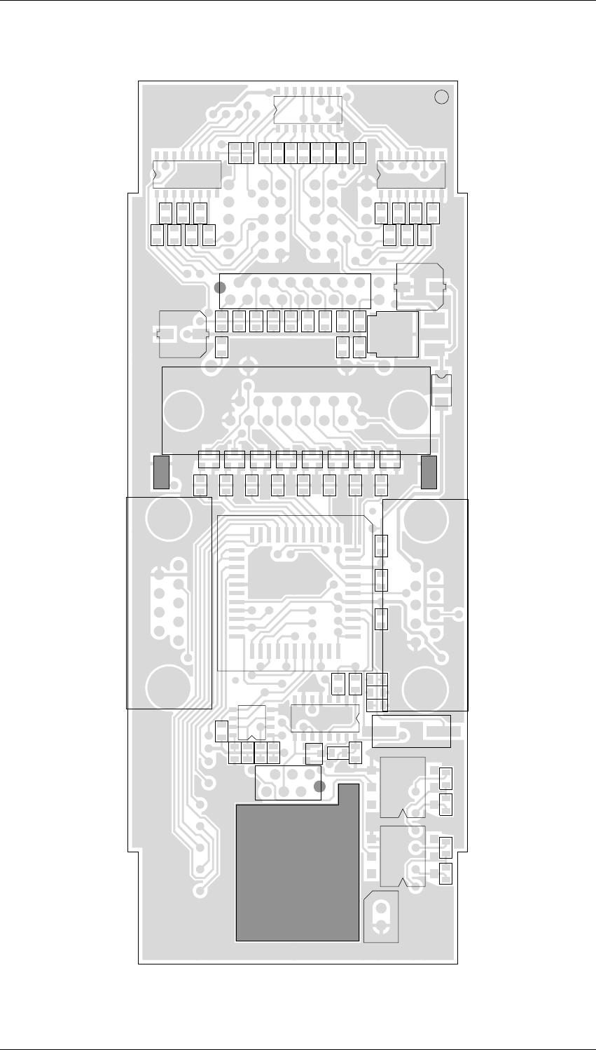
TA087-02-0000 PCB IPN 227-08701-02 Bottom Side
12
PCB Information
M087-02-001
27/07/00 Copyright TEL
ABCD
1
2
3
4
5
6
7
8
9
10
11
*C11
*C36
*C37
*C43
*C44
*IC11
C5
C6
C7
C8
D1
D2
D3
D4
DOWN
IC8
IC9
LED1LED2LED3
Q20
Q21
Q22
Q23
Q24
Q25
Q26
Q27
Q28
Q29
R10
R11
R116
R117
R118
R119
R12
R120
R121
R122
R123
R13
R14
R15R16
R17
R21
R24
R27
R32
R35
R40
R43
R46
R50
R55
R57
R63
R64
R75
R84
R85
R9
REMOTE
TBADMARK
UP
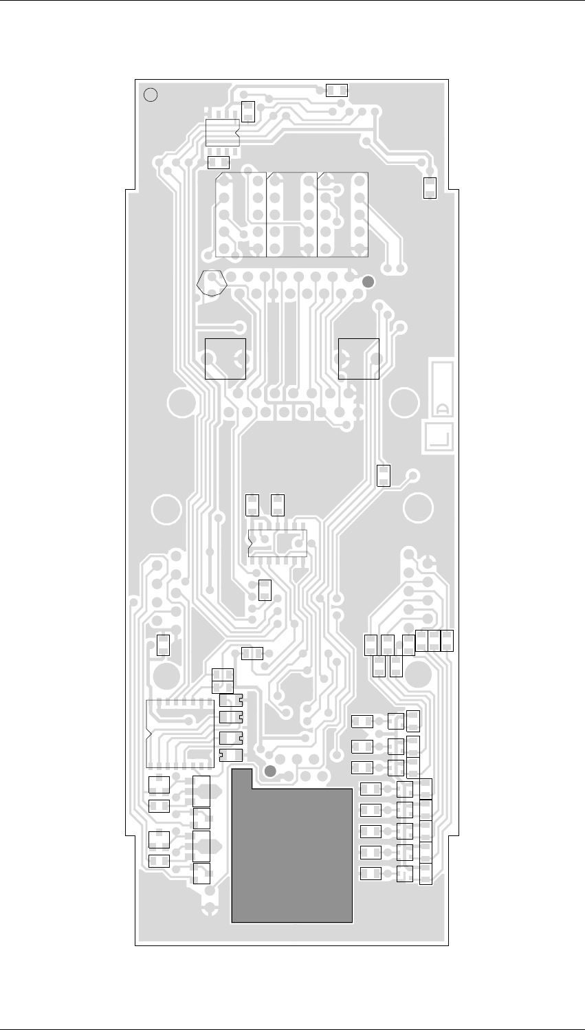
TA087-02-0000 PCB IPN 227-08701-02 Top Side
0
1
2
3
4
5
6
7
8
9
0
1
2
3
4
5
6
7
8
9
ABCDEFGHJ KLMNPQR
REV/ISS AMENDMENTS DATEAPVDD.O.CHKDDRAWN
NO.SHEETS:FILE NAME:
TAIT ELECTRONICS
IPN:
FILE DATE:
ISSUE: ID:.
2.SC.
PROJECT: DESIGNER:
1
1
TA087-02-0000
SPEAKER & CHANNEL SWITCH BOARD
a008712a
227-08701-02
11-May-00
A
TA087-01 C.P.
P1 PROTOTYPE M.HALL P.V.D.M. D.ELDER S.CRAGG 09/05/94
1A SECOND PROTOTYPE M.HALL C.PARK M.HALL JACKSON 07/04/00
QTY: IPN:1.0 002-20068-07 IC MC68HC705C8FN 1-TIME PROG MICRO (MECH PART)
C1
100N
C21
39P
C22
39P
C20
47U
C23
47U
C25
100N
C2
100N
C5
100N
C6
100N
C7
100N
IC1
68HC705C8FN
IRQ
2
TCAP
41
PA7
5
PA6
6
PA5
7
PA4
8
PA3
9
PA2
10
PA1
11
PA0
12
PB7
21
PB6
20
PB5
19
PB4
17
PB3
16
PB2
15
PB1
14
PB0
13
OSC1
43
OSC2
42
GND
22
RESET
1
VPP
4
VCC
44
NC 3
NC 18
NC 23
NC 40
PD7 39
TCMP38
SS/PD5 37
SCK/PD4 36
MOSI/PD3 35
MISO/PD2 34
TDO/PD1 33
RDI/PD0 32
PC7 24
PC6 25
PC5 26
PC4 27
PC3 28
PC2 29
PC1 30
PC0 31
SHIFT
REG
IC5
74HC595
DI
14
CK
11
LE
12
RST
10
GND
8
OE
13
VCC
16
Q0 15
Q1 1
Q2 2
Q3 3
Q4 4
Q5 5
Q6 6
Q7 7
SQH9
SHIFT
REG
IC6
74HC595
DI
14
CK
11
LE
12
RST
10
GND
8
OE
13
VCC
16
Q0 15
Q1 1
Q2 2
Q3 3
Q4 4
Q5 5
Q6 6
Q7 7
SQH9
SHIFT
REG
IC7
74HC595
DI
14
CK
11
LE
12
RST
10
GND
8
OE
13
VCC
16
Q0 15
Q1 1
Q2 2
Q3 3
Q4 4
Q5 5
Q6 6
Q7 7
SQH9
LVI
IC9
MC34064D
IN 2
GND
4
RES
1
A
B
C
D
E
F
G
A
B
C
D
E
F
G
DP
LED1
HDSP-7503
10
9
8
5
4
2
3
7
16
A
B
C
D
E
F
G
A
B
C
D
E
F
G
DP
LED2
HDSP-7503
10
9
8
5
4
2
3
7
16
A
B
C
D
E
F
G
A
B
C
D
E
F
G
DP
LED3
HDSP-7503
10
9
8
5
4
2
3
7
16
R63
100K
R10
100K
R11
100K
R12
100K
R13
100K
R14
100K
R15
100K
R16
100K
R17
100K
R21
33K
R24
33K
R65
560E
R27
33K
R32
33K
R35
33K
R40
33K
R43
33K
R46
33K
R57
100K
R86
560E
R97
560E
R110
560E
R87
560E
R100
560E
R111
560E
R90
560E
R101
560E
R91
560E
R102
560E
R50
100K
R112
560E
R92
560E
R103
560E
R113
560E
R93
560E
R104
560E
R94
560E
R105
560E
R114
560E
R95
560E
R77
10K
R106
560E
R115
560E
R96
560E
R107
560E
R53
1M
R70
4K7
R71
4K7
R52
100K
R61
100K
R74
10K
R9
100K
R62
4K7
SK1
2X8 WAY TOP ENTRY SKT
SK3
SKT 6WAY TOP ENT
SPK1
16OHM
+
-
UP
PUSH BUTTON
DOWN
PUSH BUTTON
BBADMARK
BADMARK
TBADMARK
BADMARK
IC10
4053BD
INH 6
A11
B10
C9
X0 12
X1 13
Y0 2
Y1 1
Z0 5
Z1 3
GND
8
VREF
7
+V
16
Z
4
X
14
Y
15
LK1 LK2
IC8
74HC125
9
10 8
IC8
74HC125
546
IC8
74HC125
2
1
3
IC8
74HC125
12
13
11
*IC11
MAX232
C1+
1
C1-
3
C2+
4
C2-
5
T2IN
10
T1IN
11
R1OUT
12
R2OUT
9
GND
15
+V
16
5/10V+ 2
5/10V- 6
T2OUT 7
T1OUT 14
R1IN 13
R2IN 8
*C11
100N
C10
100N
R85
10K
R84
10K
TANT
*C44
1U0
TANT
*C43
1U0
TANT
*C36
1U0
TANT
*C37
1U0
2
E PROM
IC2
X250405C
SI
5
SCK
6
CS
1
HOLD
7
GND
4
VCC
8
SO 2
WP 3
R81
100K
R82
100K
R83
100K
R66
100K
IC8
74HC125
V-
7
V+
14
C8
100N
D2
BAV99
2
3D2
BAV99
3
1
R54
10K
Q20
BSR30
R56
470
R55
100E
D1
BAW56
31 D1
BAW56
32
IC12
250VAC
462
51
D4
BAV99
2
3D4
BAV99
3
1
R73
10K
Q21
BSR30
R76
470
R75
100E
D3
BAW56
31 D3
BAW56
32
IC13
250VAC
462
51
R64
100K
21
SPEAKER
2 WAY PLUG
X1
4M
REMOTE
RED HI DIFF
21
VREG
REG5V
78M05CDT
VIN
1
GND
2
VOUT
3
D13
BAV99
2
3
D13
BAV99
3
1
D16
400V
PL3
6 EDGE CONN PINS
Q10
BC848
Q11
BC848
Q12
BC848
Q13
BC848
Q14
BC848
Q15
BC848
Q16
BC848
R20
100K
R23
47K
R22
100K
R26
47K
R25
100K
R31
47K
R30
100K
R34
47K
R33
100K
R37
47K
R36
100K
R42
47K
R41
100K
R45
47K
Q17
BC848
R44
100K
R47
47K
Q22
BC857W
R116
10K
R117
10K
Q23
BC857W
Q24
BC857W
R118
10K
Q25
BC857W
R119
10K
Q26
BC857W
R120
10K
Q27
BC857W
R121
10K
Q28
BC857W
R122
10K
Q29
BC857W
R123
10K
SK1A
15 WAY DRANGE SKT
SK2
SKT 9 WAY DRANGE TOP ENT
SK4
SKT 9 WAY DRANGE TOP ENT
SK2
GND 9
SK2
IP1 1
SK2
IP2 2
SK2
IP3 3
SK2
IP4 4
SK2
IP5 5
SK2
IP6 6
SK2
IP7 7
SK2
IP8 8
SK1
+13V8 15
SK1
GND 11
SK1
GND 2
SK1
SPKR+ 7
SK1
SPKR+ 9
SK1A GND
9
SK3 GND
2
SK3 SPKR+
3
SK3 SERIAL-COM
4
SK1A +13V8
15
SK4 RS232-RXD
3
SK4
OPTO-KEY-DOWN-
8
SK4
OPTO-KEY-DOWN+
7
SK4
OPTO-KEY-UP+
4
SK4
OPTO-KEY-UP-
6
SK4 RS232-TXD
2
+5V
+13V8
+5V +5V
+5V
+5V
+5V
+5V
+5V
+5V
+5V
+5V
+5V
+5V
+5V
+5V
+5V+5V
+5V
+5V
+5V
+5V +5V
+5V
+5V
+5V +5V
+5V
+5V
+5V +5V +5V +5V
+5V
+5V
+13V8
+5V
+5V
+5V
SK1A
GND 1
SK4
GND 5
SK1A
+13V8 8
SK4
+13V8 1
SK1
CH-SELECT-1 12
SK1
CH-SELECT-2 10
SK1
CH-SELECT-3 8
SK1
CH-SELECT-4 6
SK1
CH-SELECT-5 4
SK1
CH-SELECT-6 3
SK1
CH-SELECT-7 5
+5V
+5V
+5V
+5V
+5V
+5V
+5V
SK1
CH-SELECT-8 1
+5V
SK1A
3
SK1A
2
SK1A
10
SK1A
11
SK1A
12
SK1A
13
SK1A
14
+5V
+5V
+5V
+5V
+5V
+5V
+5V
+5V
+5V
SOCKET RJ11 BULKHEAD
RESET
KEY-UP KEY-DOWN
SERIAL-COM
M087-02-001
Cable and Connector Specifications
15
Copyright TEL 27/07/00
5 Cable and Connector Specifications
Programming and speaker connector
The programming connector uses the 6 pin RJ11 connector (PL3).
Channel output connector
The channel output connector uses two connectors, one 16 pin micromatch connector
(SK1) and one 15 pin D-range connector (SK1A).
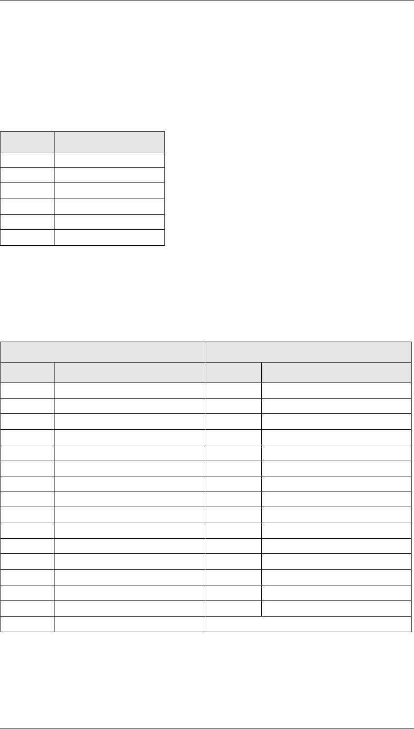
Pin No. Description
1N/C
2N/C
3 SERIAL_COMM
4 SPEAKER_+IVE
5 GND
6N/C
16 pin micromatch (SK1) 15 pin D-range (SK1A)
Pin No. Description Pin No. Description
1 CH-SELECT-8 1 GND
2 GND 2 CH-SELECT-6
3 CH-SELECT-6 3 CH-SELECT-7
4 CH-SELECT-5 4 N/C
5 CH-SELECT-7 5 N/C
6 CH-SELECT-4 6 N/C
7 SPEAKER_+IVE 7 N/C
8 CH-SELECT-3 8 +13V
9 SPEAKER_+IVE 9 GND
10 CH-SELECT-2 10 CH-SELECT-5
11 GND 11 CH-SELECT-4
12 CH-SELECT-1 12 CH-SELECT-3
13 GND 13 CH-SELECT-2
14 N/C 14 CH-SELECT-1
15 +13V 15 +13V
16 N/C

16
Cable and Connector Specifications
M087-02-001
27/07/00 Copyright TEL
Channel input connector
The channel input connector uses a 9 pin D-range connector (SK2).
Opto-coupled remote control and Optional serial
channel data output connector
This connector uses the 9 pin D Range connector (SK4) - optional in later models.
Pin No. Description
1IP1
2IP2
3IP3
4IP4
5IP5
6IP6
7IP7
8IP8
9 GND
Pin No. Description
1 +13V
2 RS232-TXD
3 RS232-RXD
4 OPTO_KEY_UP+
5 GND
6 OPTO_KEY_UP-
7 OPTO_KEY_DOWN+
8 OPTO_KEYDOWN-
9N/C

M087-02-001
Installation
17
Copyright TEL 27/07/00
6Installation
1. Mount the module in the rack in the allocated slot and connect it to the rack via
the 219-02661-00 cable supplied. The cable plugs into the BACKPLANE PCB at the
rear of the rack.
2. Set the 8 pin DIP switches located on the BACKPLANE PCB to OFF
3. Ensure that the receiver and transmitter modules are programmed to the correct
frequencies with PGM800Win.
4. To program the Channel Change module use the standard T800 Series II
programming cable to connect to a PC. Run PGM S/W: TA2213A914 under
Windows. Refer to the Programming section, if more detailed information is
required.
5. If the module needs to be set up for external channel selection and monitoring,
refer to Operation section.

18
Operation
M087-02-001
27/07/00 Copyright TEL
7 Operation
The TA087-02-0000 module operates either in Local Mode or in Remote Mode. The
mode in which the module powers up is determined by the module programing.
If no channel data have been programmed into the module, the display will blink "E"
and the keys will not operate.
If a channel label exceeds 999, the display will show "- - -".
If the channel label is set to “BLANK”, the display will show "_ _ _".
Local Mode
If Local Mode is set in the programming software, the module will power up in Local
Mode.
In Local Mode, channel selection takes place via the up and down buttons. When either
button is pressed the displays starts blinking with the new channel selected and remains
blinking for 3 seconds after release of the button. When the blinking times out, the
actual channel information is downloaded to the outputs of the module.
Following the highest channel, the display shows "- - -" for 3 seconds and then wraps
around to the first channel, and visa versa.
When Remote Mode was programmed the module will revert to Local Mode when
either Up or Down button is pressed.
To change from Local Mode to Remote Mode
Manual
Select "- - -" with the up down buttons and release the button. After 3 seconds the
module will change to REMOTE Mode.
Automatic
When the Remote Revert Time is set to 0 during programming, the module will not
automatically revert to Remote mode. If the Remote Revert Time is set to any other
non-zero value, the module will revert to Remote Mode. The time window is between 0
and 255 minutes. This feature avoids the situation whereby the technician forgets to
revert the module to Remote, rendering the base station inoperable.

M087-02-001
Operation
19
Copyright TEL 27/07/00
Remote Mode
A red LED on the front panel of the module indicates the Remote Mode
To Select Remote Mode
Automatically
At Power up if the Remote Mode was set during programming
From Local Mode when the Remote Revert Time was set to a non zero value during
programming
Manually
From Local mode, select "- - -" with the up and down buttons and release the buttons.
After 3 seconds the module will change to Remote Mode.
Inputs in Remote Mode
The module accepts 8 binary / BCD inputs in the Remote mode with standard or
polarity reversed logic levels. The inputs are available on a 9 way D Range Socket PL2.
pin 1: Ch Select 0
pin 2: Ch Select 1
. . . . . . . . . . . . . . . . . . . . . . .
pin 8: Ch Select 7
pin 9: Gnd
Logic 1 = high (5V or higher) or open collector. The module provides 10k pull up to +5V.
Logic 0 is 0V
For Binary input with standard logic
CH 0 00000000
CH 1 00000001
. . . . . . . . . . . . . . . . . . . . . . . . . . .
CH 127 01111111
For BCD input with standard logic
CH 0 0000 0000
CH 1 0000 0001
. . . . . . . . . . . . . . . . . . . . . . . . . . .
CH 127 1001 1001
If the value of the remote inputs is higher than the highest channel programmed in the
module, the display will display the programmed default label and outputs the
programmed default channel.

20
Operation
M087-02-001
27/07/00 Copyright TEL
Outputs in Remote Mode
Channel select outputs to the radio follow the T800 format
The optionally available RS232 output to read the channel label of the current channel,
is at present only available in hardware. Specification of the communication protocol is
yet to be specified.
Speaker
The speaker in the TA0087-02-0000 is automatically connected to the Back Plane of the
T800 rack. For reasons of convenience the speaker signals are also available on the
programming connector at the back of the of the TA087-2-0000 module via a 6 way
micromatch connector, or at the front via the RJ11 connector.
M087-02-001
Programming
21
Copyright TEL 27/07/00
8 Programming
Requirements
■IBM compatible PC with 800x600 screen resolution running Windows95 or
better
■T800 Programming lead
■PGM087: TA2213A914
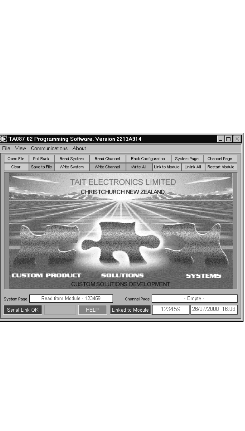
1. 1. Run TA2213A914.EXE.
The Home Page looks as follows:
Com Port select
Select "Communications" on the Menu Bar, select "Comport" and select "Com1 or
Com2".
Printing
Select "File" and "Print" on the Menu Bar and
22
Programming
M087-02-001
27/07/00 Copyright TEL
Poll Rack
Click on " Poll Rack " to show the equipment in the rack. The list is display only.
Click on " Exit " to return to the Home Page
Read System
This button will bring up a selection screen, displaying the TA0087 modules only.
Select the TA0087 module you want the address by clicking on its serial number. The
click on " OK ".
The program will now link to the module. The LED display of the TA0087 module will
show " -L- ". The programming software will display a green field " linked" to the
module selected.
Following a successful read the System Page will be displayed
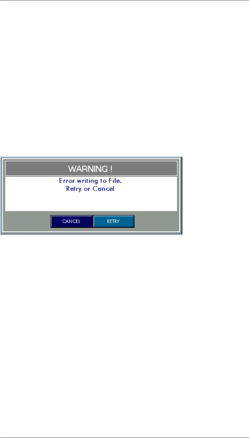
In the event an error is made with changes the following warning message will be
displayed
M087-02-001
Programming
23
Copyright TEL 27/07/00
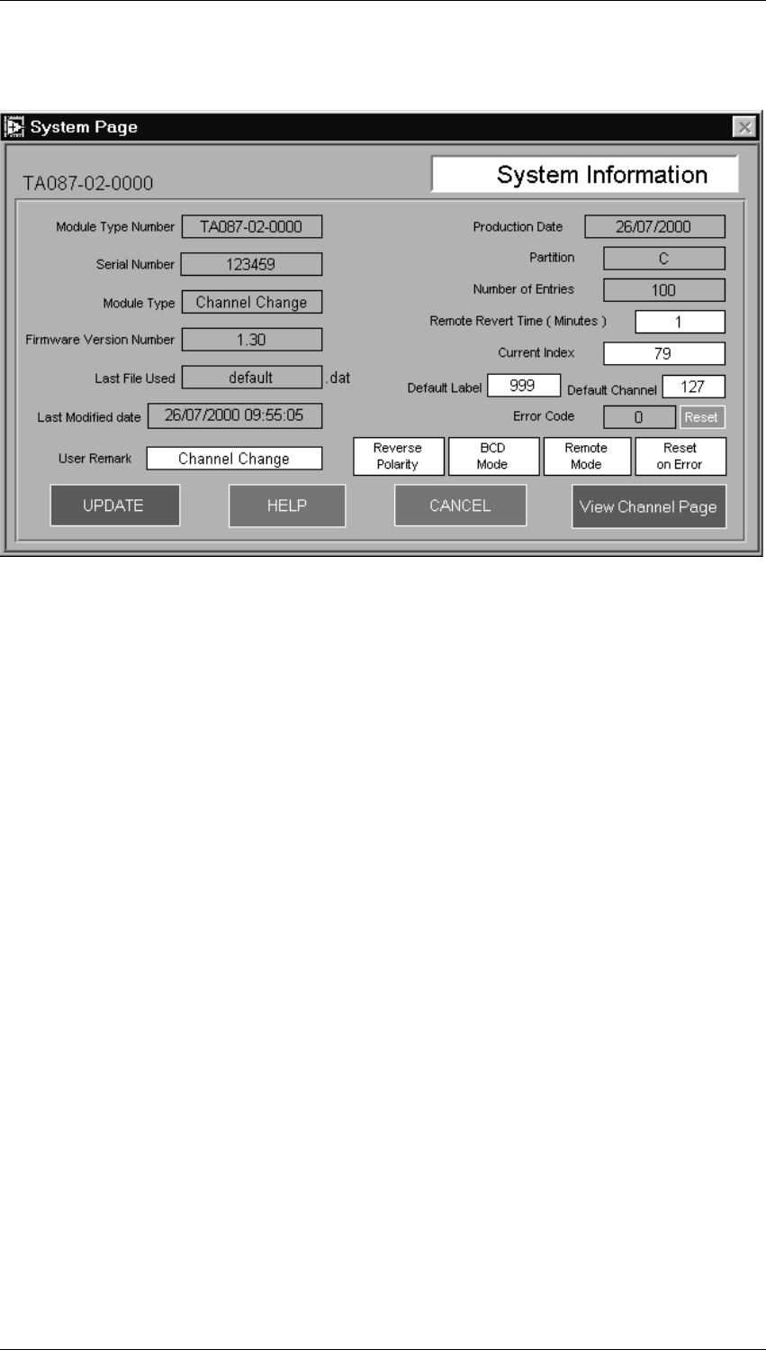
System Page
User modifiable fields are white, others are grey
Remote Revert Time
Enter any value between 0 and 255. The number entered gives in minutes the time the
module takes to revert to Remote Mode after the module was put in Local Mode.
When 0 is entered the module will not revert to Remote Mode.
Current Index
This field determines the channel the TA0087 will point to upon power up in Local
Mode. The number relates to the first column of channel data information. Click on
" View Channel Data " for a quick glance.
Rerverse Polarity
BCD Mode
Local Mode or Remote Mode
Selection of the mode by this button determines the operating mode upon power up.

24
Programming
M087-02-001
27/07/00 Copyright TEL
Reset on Error
The software of the TA0087 module checks for processing errors and records the nature
of the error. If the Reset on Error flag is set to " No Reset on Error ", the module will stop
operating, display " Exx ". The module will exit this mode either by a power cycle or by
the reset directive from the programming software. Refer to " Restart Module " on the
home page.
If the Reset on Error is chosen, the module will store the error code and reset its processor.
Will it still work?
The following fields will be automatically updated
" Last File used "
" Last Modified Date "
" Number of Entries "
Update
When changes to the System Page are complete, click on the " Update " button. The
software holds the information but does not write to the TA0087 module.
Exit
Click on " Exit " to return to the Home Page without saving any changes made.
View Channel Data
This button brings up the Channel Data Page, provided it has been opened before by the
" Read Channel Data " on the Home Page.
M087-02-001
Programming
25
Copyright TEL 27/07/00
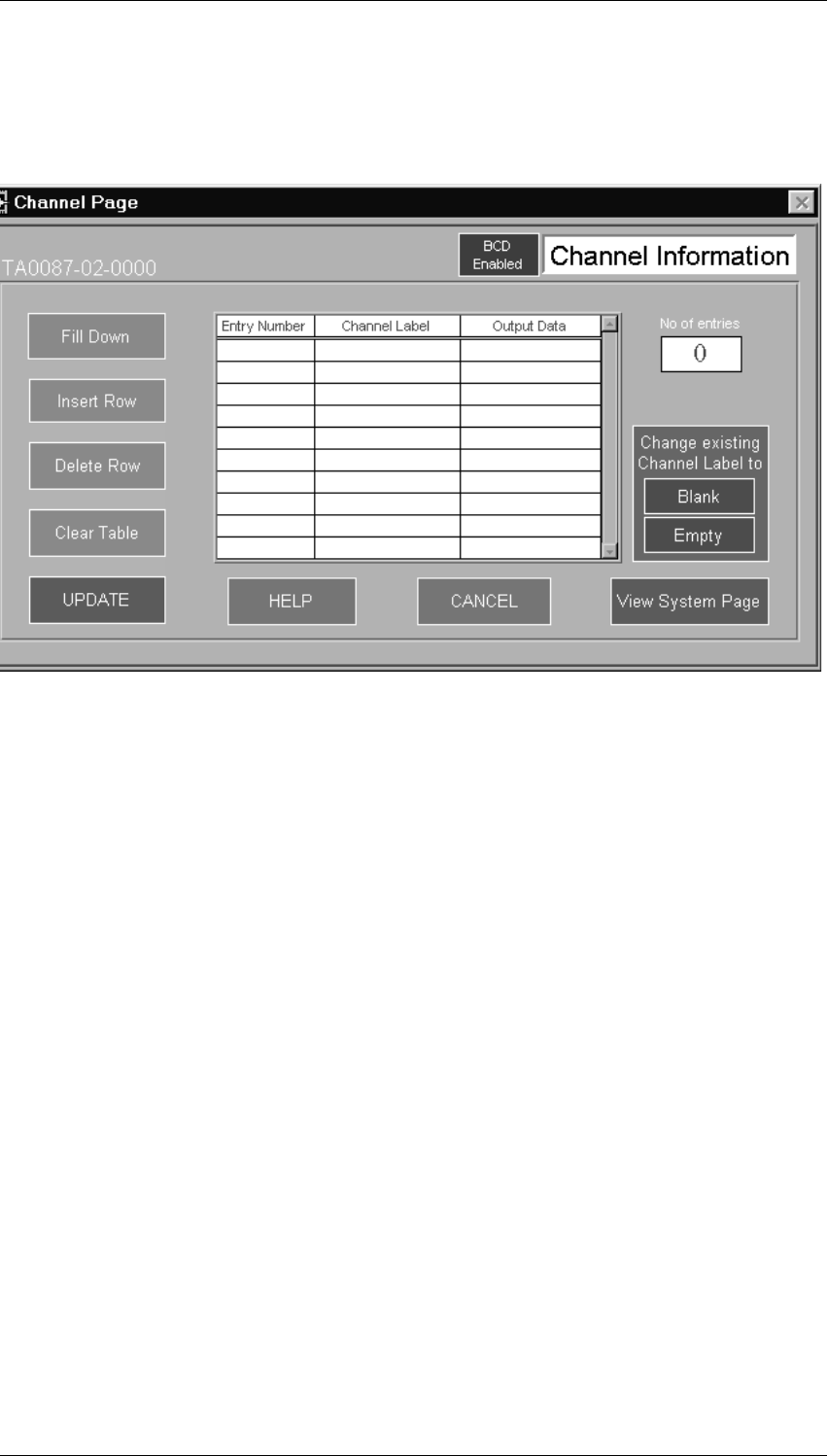
Channel Data Page
Click on the " Read Channel Data/All " button on the Home Page. The display will look
as follows
It will take about 20 seconds to read and display a channel information page with 64 for
entries.
The first column on the page shows a numeric listing of all channels entered, which is
automatically updated when changes are made. The number in this list is used on the
System Page for the " Current Index "
The second column requires input from the operator to show the channel labels. The
column accepts any number between 0 and 999. Alphanumeric characters will not be
accepted.
Multiple entries are allowed. The program will display a warning message at the first
multiple entry. If the message is ignored, no further warnings for multiple entries will
pop up. Otherwise the warning message will keep coming.
In the third column the operator has to enter the actual channel number to input to the
RF modules. Any value between 0 and 127 will be accepted. There will be no multiple
entry warnings for this column.
Channel Labels
Add a row
To add a channel to the list places the cursor below the last entry in any column. Use
SHIFT-ARROW to move to the other columns and enter data as required. The first
column will automatically adjust.

26
Programming
M087-02-001
27/07/00 Copyright TEL
Insert a row
Place the cursor in the field below the line to be inserted and click on " Insert Line ".
Edit the new Line as above.
Delete a row
Place the cursor in any field of the line to be deleted and click on " Dell Line ". The first
column will update itself automatically. Make sure that the " Current Index " is still
correct.
Clear Table
Clears all three columns
Update
As with the System page the program stores the changes but does not write to the
module as yet. The program returns to the Home Page for further instructions.
Exit
Click on " Exit " to return to the Home Page without saving any changes made.
View System Data
This button brings up the System Data Page. Note that this display is view only.

M087-02-001
Programming
27
Copyright TEL 27/07/00
Home Page
Program the module
Click on the " Write System ", " Write Channel " or " Write All " to reprogram the
module as required.
" Write System " updates the System Page only.
" Write Channel " updates the Channel Data plus the " Number of Entries " and the "
Last programmed date and time " of the System Page.
Following completion of a write the display will show " Write OK " or " Write Fail ".
When fail, try again. Otherwise refer to the service manual for trouble shooting.
Link/Unlink
Click on "Link " to display a list of TA0087 modules one can link to. Click on the serial
number to link to a module.
Click on Unlink for the opposite
Restart
This button reboots the CPU in the TA0087.
New / Clear
Resets all variables in the program to allow you to start from scratch starting with the
System Page.
Open File
Standard Windows feature

28
Programming
M087-02-001
27/07/00 Copyright TEL
Save to File
Standard Windows feature
The remaining " Display ... " buttons display as described and cannot be modified by the
operator.

M087-02-001 Fault Finding 29
Copyright TEL 27/07/00
9Fault Finding
Supply problems
The unit derives its power from the T800 rack plane PCB.
Check for 13.8V and +5V at in and output of the regulator IC at C20 and C23.
1. Without +13.8V at C20 check cable and T800 rack plane PCB.
If no +5V, check VREG for levated temperature. A short on the board will cause
the regualtor to heat up. A faulty regulator will be cold. Replace regulator as
required.
2. 5V regulator voltage low: Disconnect all cables - except the power cable. Check for
components heated up. Use your judgement to either replace the component or
check it's output for overloaded conditions. Also check for dry joints on inputs.
No channel selection
The unit does not respond to neither local nor remote inputs.
1. Check database by reading the unit. If OK skip 2 and 3
2. Check reset input of microprocessor. Make sure input level is +5V. If not check
power supply and follow up with procedure for 5V reg.
3. Check oscillator running at 4MHz. Replace Xtal first followed by micro if still not
succesfull.
4. Check IRQ input should be +5V. If not work your way back through IC8 and IC 10
to the serial com input. Make sure that the inhibit input at IC10-6 is 0V.
5. Check logic levels for up and down signals on the processor IC1 pin26 & pin 27. If
low check opto-couplers.
No Display
1. Check the programming of the unit
2. Check for presence of Data, Clock Latch Enable on IC5, 6 and 7, while toggling
the up down buttons.
3. No RS232 response
RS232 is not yet supported in software

30
IC Data Sheets
M087-02-001
27/07/00 Copyright TEL
10 IC Data Sheets
