Instruction Manual
User Manual: Pdf
Open the PDF directly: View PDF ![]() .
.
Page Count: 123 [warning: Documents this large are best viewed by clicking the View PDF Link!]


PAGE 1 OF 3
SPELLMAN HIGH VOLTAGE ELECTRONICS CORPORATION
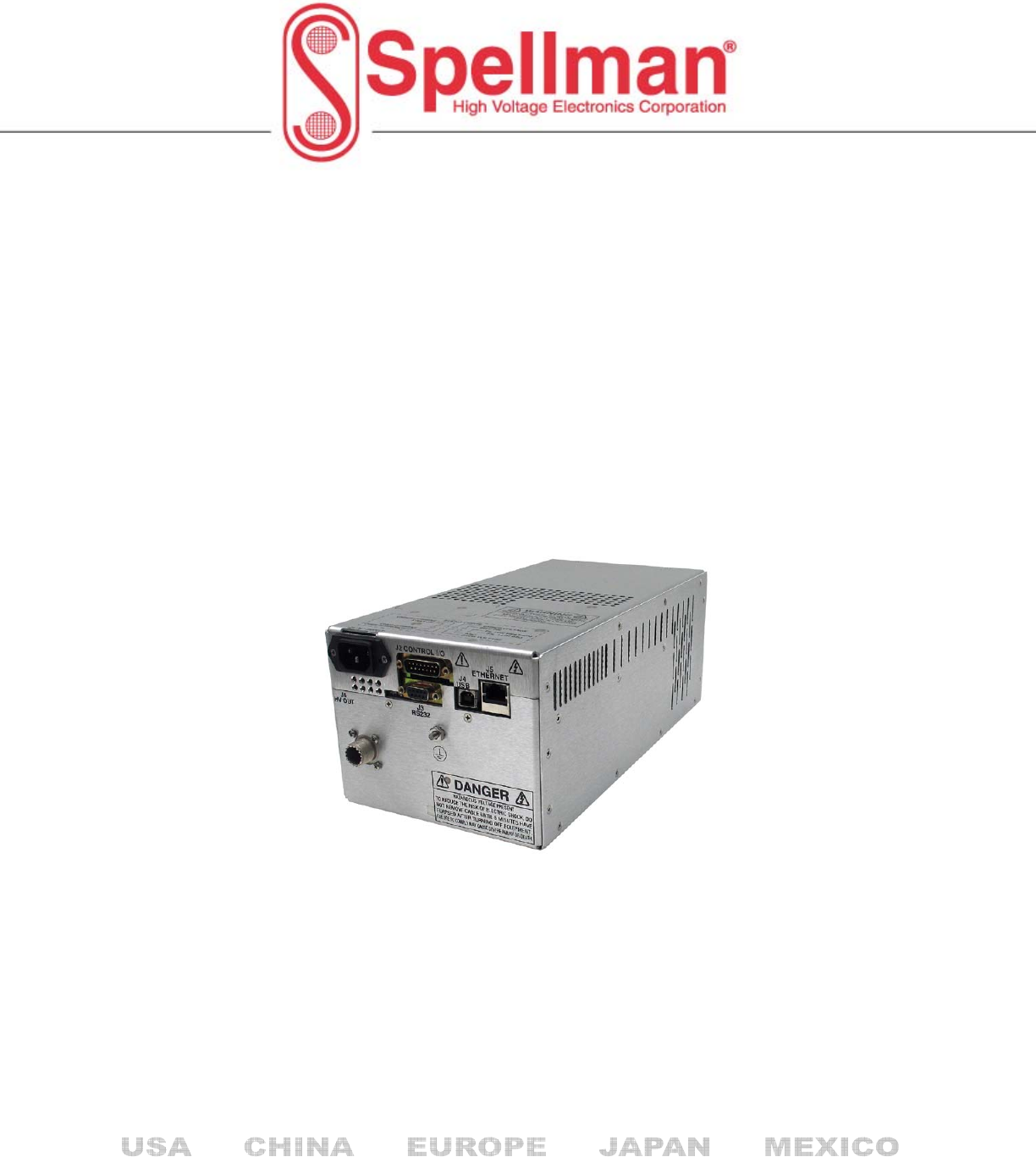
300W-1200W HIGH
VOLTAGE MODULE
Spellman’s SLM Series of high voltage modules are
designed for OEM applications up to 70kV at 1200 watts.
Its universal input, small package size and choice of three
standard digital interfaces simplifies integrating the SLM
into your system design. Models are available in either
positive or negative polarity. The SLM is fully arc and
short protected. Excellent regulation specifications are
provided along with outstanding stability performance.
TYPICAL APPLICATIONS
Capacitor Charging
HiPot Testing
CRT Testing
Electrostatics
E Beam Systems
CW Lasers
FIRMWARE CONFIGURATIONS
STANDARD BASED FEATURES
AOL Adjustable Overload Trip
AT Arc Trip
NAD No Arc Detect
NSS No Slow Start
PSS Programmable Slow Start
RFR Remote Fault Reset
RMI Remote Mode Indicators
ROV Remote Overvoltage Adjust
SPECIFICATIONS
Input Voltage:
Power factor corrected input, ≥0.98
90-264Vac, 47-63 Hertz, for 300 watt units
180-264Vac, 47-63 Hertz for 600 and 1200 watt units
Output Voltage:
11 models—1kV to 70kV
Output Polarity:
Negative or positive, specify at time of order
Local Indicators:
Arc, HV On, Temp Error, OVP, I Mode
Power On, OC, Reg Error
Power:
3 power ranges available—300, 600 and 1200 watts.
Other power levels available on special order.
Voltage Regulation:
≤0.01% of rated output voltage over specified
input voltage range
≤0.01% of rated output voltage for a full load change
Current Regulation:
≤0.01% of rated output current over specified
input voltage range
≤0.01% of rated output current for a ±100µA
for a full voltage change
Ripple:
≤0.2% rms of maximum rated voltage,
measured with a 10 foot long HV cable
Stability:
≤50ppm/hr after a 2 hour warm up
Temperature Coefficient:
≤100ppm per degree C
Environmental:
Temperature Range:
Operating: 0˚C to 40˚C
Storage: -40˚C to 85˚C
Humidity:
20% to 85% RH, non-condensing.
Control Interface
Local Interface:
Potentiometers are provided to adjust voltage and current.
Remote Interface: USB, Ethernet and RS232 are standard,
implemented with 12 bits of resolution.
All digital monitors have an accuracy specification of 2%.
Control Software: A VB GUI will be provided for
RS-232/USB, the Ethernet interface will have an embedded
applet for control.
HV Control Enable/Interlock:
A dry contact, hardware based interlock is provided for
remote mode. In local mode this I/O is the enable.
Monitor Signals:
Voltage and current monitor signals are scaled 0-10Vdc
equals 0-100% of full scale, accuracy is 1%.
Cooling:
Forced air
Dimensions:
300/600 watts:
4.75˝ H X 6˝ W X 12˝ D (120.65mm x 152.4mm x 304.8mm)
1200 watts:
4.75˝ H X 12˝ W X 12˝ D (120.65mm x 304.8mm x 304.8mm)
Weight:
300/600 watts: 14 pounds (6.35kg)
1200 watts: 26 pounds (11.8kg)
•COMPACT & LIGHTWEIGHT
•MODELS FROM 1KV-70KV, 300W, 600W AND 1200W
•UNIVERSAL INPUT, POWER FACTOR CORRECTED
•LOW COST MODULAR DESIGN
•STANDARD DIGITAL INTERFACES: USB,
ETHERNET AND RS-232
SLM
1200W
300W-600W
www.spellmanhv.com/manuals/SLM
Corporate Headquarters
Hauppauge, New York USA
+1-631-630-3000 FAX: +1-631-435-1620
e-mail: sales@spellmanhv.com
www.spellmanhv.com 128035-001 REV. K
Spellman High Voltage is an ISO 9001:2008 and ISO 14001:2004 registered company
For locations worldwide
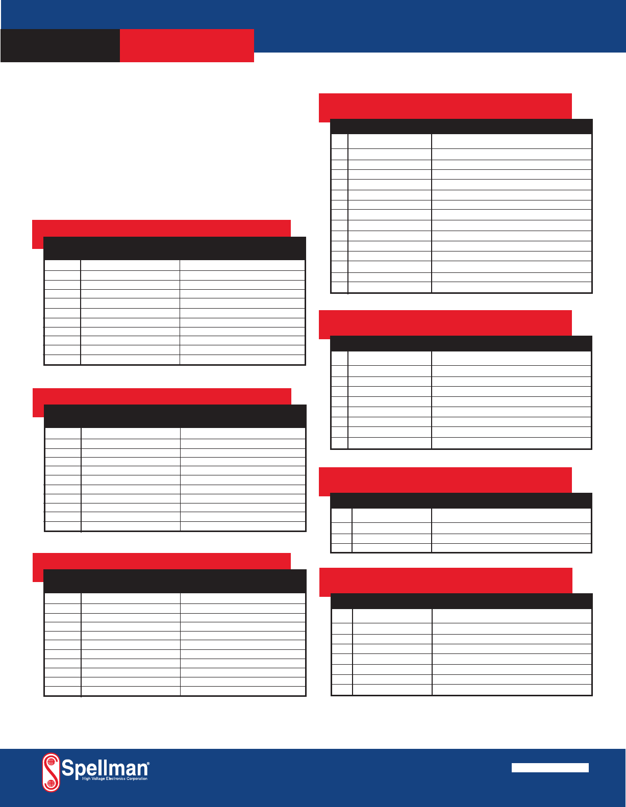
ETHERNET DIGITAL INTERFACE—
J5 8 PIN RJ45 CONNECTOR
PIN SIGNAL SIGNAL PARAMETERS
1 TX+ Transmit Data +
2 TX- Transmit Data -
3 RX+ Receive Data +
4 NC No Connection
5 NC No Connection
6 RX- Receive Data -
7 NC No Connection
8 NC No Connection
PAGE 2 OF 3
SLM SELECTION TABLE- 300W
300 Watt
kV mA Model
1 300 SLM1*300
3 100 SLM3*300
5 60 SLM5*300
10 30 SLM10*300
15 20 SLM15*300
20 15 SLM20*300
30 10 SLM30*300
40 7.5 SLM40*300
50 6 SLM50*300
60 5 SLM60*300
70 4.28 SLM70*300
RS-232 DIGITAL INTERFACE—
J3 9 PIN FEMALE D CONNECTOR
PIN SIGNAL SIGNAL PARAMETERS
1 NC No Connection
2 TX out Transmit Data
3 RX in Receive Data
4 NC No Connection
5 SGND Ground
6 NC No Connection
7 NC No Connection
8 NC No Connection
9 NC No Connection
*Specify “P” for positive polarity or “N” for negative polarity
USB DIGITAL INTERFACE—
J4 4 PIN USB “B” CONNECTOR
PIN SIGNAL SIGNAL PARAMETERS
1 VBUS +5 Vdc
2 D- Data -
3 D+ Data +
4 GND Ground
SLM ANALOG INTERFACE—
J2 15 PIN MALE D CONNECTOR
PIN SIGNAL SIGNAL PARAMETERS
1 Power Supply Fault Open Collector, 35V @ 10mA Maximum
2 Current Program In 0 to 10V=0 to 100% Rated Output, Zin=10MΩ
3 Voltage Program In 0 to 10V=0 to 100% Rated Output, Zin=10MΩ
4 NC No Connection
5 Local Voltage Prog. Multi-turn front panel potentiometer
6 NC No Connection
7 Local Current Prog. Multi-turn front panel potentiometer
8 Voltage Monitor 0 to 10V=0 to 100% Rated Output, Zout =4.99k, 1%
9 Signal Ground Ground
10 Current Monitor 0 to 10V=0 to 100% Rated Output, Zout =4.99k, 1%
11 HV Enable Input Connect to Pin 12 to HV Enable Supply
12 HV Enable Output +15V @ Open, ≤15mA @ Closed
13 NC No Connection
14 HV On Output Signal Open Collector, 35V @10mA Maximum
15 Spare No Connection
SPELLMAN HIGH VOLTAGE ELECTRONICS CORPORATION
300W-1200W HIGH
VOLTAGE MODULE
SLM
SLM SELECTION TABLE- 600W
600 Watt
kV mA Model
1 600 SLM1*600
3 200 SLM3*600
5 120 SLM5*600
10 60 SLM10*600
15 40 SLM15*600
20 30 SLM20*600
30 20 SLM30*600
40 15 SLM40*600
50 12 SLM50*600
60 10 SLM60*600
70 8.56 SLM70*600
*Specify “P” for positive polarity or “N” for negative polarity
SLM SELECTION TABLE- 1200W
1200 Watt
kV mA Model
1 1200 SLM1*1200
3 400 SLM3*1200
5 240 SLM5*1200
10 120 SLM10*1200
15 80 SLM15*1200
20 60 SLM20*1200
30 40 SLM30*1200
40 30 SLM40*1200
50 24 SLM50*1200
60 20 SLM60*1200
70 17.14 SLM70*1200
*Specify “P” for positive polarity or “N” for negative polarity
Input Line Connector:
IEC320 cord set with integrated EMI filter
Output Cable:
A detachable 10’ (3.3m) long shielded HV cable is provided
Regulatory Approvals:
Compliant to 204/108/EC, the EMC Directive and 2006/95/EC,
the Low Voltage Directive. UL/CUL recognized, File 227588;
300W and 600W only.
Corporate Headquarters
Hauppauge, New York USA
+1-631-630-3000 FAX: +1-631-435-1620
e-mail: sales@spellmanhv.com
www.spellmanhv.com 128035-001 REV. K
Spellman High Voltage is an ISO 9001:2008 and ISO 14001:2004 registered company
For locations worldwide
PAGE 3 OF 3
SPELLMAN HIGH VOLTAGE ELECTRONICS CORPORATION
300W-1200W HIGH
VOLTAGE MODULE
SLM
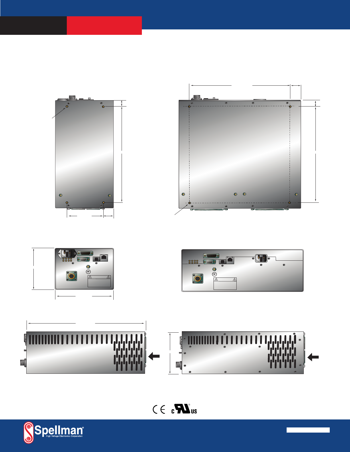
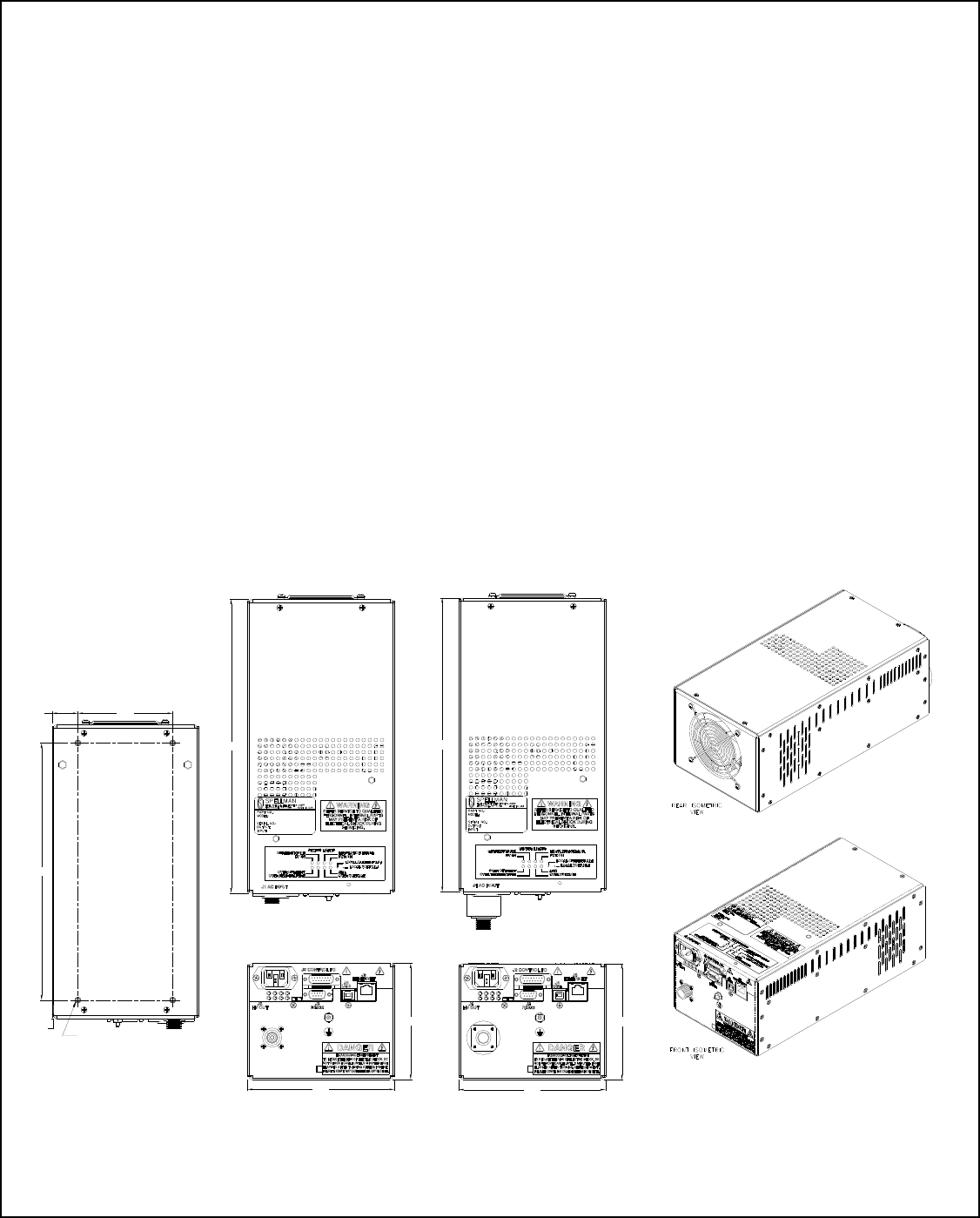
DIMENSIONS: in.[mm]
FRONT VIEW
BOTTOM VIEW
12.00 [304]
4.75 [120]
10.50 [266]
0.75 [19]
10-32 BLIND
PEMS
4 PLCS
6.00 [152]
1.06 [27]
3.88 [99]
DANGER
HIGH
VOLTAGE
SIDE VIEW
J2 CONTROL I/O
FILAMENT
J4
USB
J5
ETHERNET
J3
RS 232
FRONT VIEW
BOTTOM VIEW
4.75 [120]
10.50 [266]
0.75 [19]
1.06 [27]
9.875 [250.36]
SIDE VIEW
10-32 BLIND
PEMS
4 PLCS
DANGER
HIGH
VOLTAGE
J2 CONTROL I/O
FILAMENT
J4
USB
J5
ETHERNET
J3
RS 232
AIR
FLOW
AIR
FLOW
1200 Watt
300/600 Watt
Corporate Headquarters
Hauppauge, New York USA
+1-631-630-3000 FAX: +1-631-435-1620
e-mail: sales@spellmanhv.com
www.spellmanhv.com 128035-001 REV. K
Spellman High Voltage is an ISO 9001:2008 and ISO 14001:2004 registered company
For locations worldwide
PAGE 2 OF 2
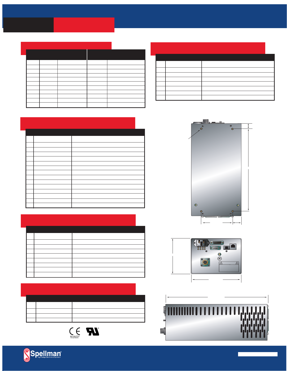
DIMENSIONS: in.[mm]
SLM SELECTION TABLE- 300W, 600W
300 Watt 600 Watt
kV mA Model mA Model
1 300 SLM1*300 600 SLM1*600
3 100 SLM3*300 200 SLM3*600
5 60 SLM5*300 120 SLM5*600
10 30 SLM10*300 60 SLM10*600
15 20 SLM15*300 40 SLM15*600
20 15 SLM20*300 30 SLM20*600
30 10 SLM30*300 20 SLM30*600
40 7.5 SLM40*300 15 SLM40*600
50 6 SLM50*300 12 SLM50*600
60 5 SLM60*300 10 SLM60*600
70 4.28 SLM70*300 8.56 SLM70*600
RS-232 DIGITAL INTERFACE—
J3 9 PIN MALE D CONNECTOR
PIN SIGNAL SIGNAL PARAMETERS
1 NC No Connection
2 TX out Transmit Data
3 RX in Receive Data
4 NC No Connection
5 SGND Ground
6 NC No Connection
7 NC No Connection
8 NC No Connection
9 NC No Connection
*Specify “P” for positive polarity or “N” for negative polarity
ETHERNET DIGITAL INTERFACE—
J5 8 PIN RJ45 CONNECTOR
PIN SIGNAL SIGNAL PARAMETERS
1 TX+ Transmit Data +
2 TX- Transmit Data -
3 RX+ Receive Data +
4 NC No Connection
5 NC No Connection
6 RX- Receive Data -
7 NC No Connection
8 NC No Connection
USB DIGITAL INTERFACE—
J4 4 PIN USB “B” CONNECTOR
PIN SIGNAL SIGNAL PARAMETERS
1 VBUS +5 Vdc
2 D- Data -
3 D+ Data +
4 GND Ground
FRONT VIEW
BOTTOM VIEW
12.00 [304]
4.75 [120]
10.50 [266]
0.75 [19]
10-32 BLIND
PEMS
4 PLCS
6.00 [152]
1.06 [27]
3.88 [99]
DANGER
HIGH
VOLTAGE
SIDE VIEW
J2 CONTROL I/O
FILAMENT
J4
USB
J5
ETHERNET
J3
RS 232
SLM ANALOG INTERFACE—
J2 15 PIN MALE D CONNECTOR
PIN SIGNAL SIGNAL PARAMETERS
1 Power Supply Fault Open Collector, 50V @ 10mA Maximum
2 Current Program In 0 to 10V=0 to 100% Rated Output, Zin=10MΩ
3 Voltage Program In 0 to 10V=0 to 100% Rated Output, Zin=10MΩ
4 NC No Connection
5 Local Voltage Prog. Multi-turn front panel potentiometer
6 NC No Connection
7 Local Current Prog. Multi-turn front panel potentiometer
8 Voltage Monitor 0 to 10V=0 to 100% Rated Output, Zout =4.99k, 1%
9 Signal Ground Ground
10 Current Monitor 0 to 10V=0 to 100% Rated Output, Zout =4.99k, 1%
11 HV Enable Input Connect to Pin 12 to HV Enable Supply
12 HV Enable Output +15V @ Open, ≤15mA @ Closed
13 NC No Connection
14 HV On Output Signal Open Collector, 50V @10mA Maximum
15 Spare No Connection
SPELLMAN HIGH VOLTAGE ELECTRONICS CORPORATION
300W/600W HIGH
VOLTAGE MODULE
SLM
USA +1-631-630-3000 FAX: +1-631-435-1620
UK +44 (0)1798 877000 FAX: +44 (0)1798 872479
JAPAN +81 (0)48-447-6500 FAX: +81 (0)48-447-6501
CHINA +86 (0)512-67630010 FAX: +86 (0)512-67630030
e-mail: sales@spellmanhv.com
www.spellmanhv.com 128035-001 REV.C
Spellman High Voltage is an ISO 9001:2000 and ISO 14001:2004 registered company
E227588

IMPORTANT SAFETY PRECAUTIONS
SAFETY
THIS POWER SUPPLY GENERATES VOLTAGES THAT ARE DANGEROUS AND MAY BE FATAL.
OBSERVE EXTREME CAUTION WHEN WORKING WITH THIS EQUIPMENT.
High voltage power supplies must always be grounded.
Do not touch connections unless the equipment is off and the
Capacitance of both the load and power supply is discharged.
Allow five minutes for discharge of internal capacitance of the power supply.
Do not ground yourself or work under wet or damp conditions.
SERVICING SAFETY
.
Maintenance may require removing the instrument cover with the power on.
Servicing should be done by qualified personnel aware of the electrical hazards.
WARNING note in the text call attention to hazards in operation of these units
that could lead to possible injury or death.
CAUTION notes in the text indicate procedures to be followed to avoid possible
damage to equipment.
Copyright © 2000, Spellman High Voltage Electronics Corporation. All Rights Reserved.
This information contained in this publication is derived in part from proprietary and patent data. This information has
been prepared for the express purpose of assisting operating and maintenance personnel in the efficient use of the
model described herein, and publication of this information does not convey any right to reproduce it or to use it for
any purpose other than in connection with installation, operation, and maintenance of the equipment described.
118004-001 REV. B

WICHTIGE SICHERHEITSHINWEISE
SICHERHEIT
DIESES HOCHSPANNUNGSNETZTEIL ERZEUGT LEBENSGEFÄHRLICHE HOCHSPANNUNG.
SEIN SIE SEHR VORSICHTIG BEI DER ARBEIT MIT DIESEM GERÄT.
Das Hochspannungsnetzteil muß immer geerdet sein.
Berühren Sie die Stecker des Netzteiles nur, wenn das Gerät ausgeschaltet ist und die elektrischen
Kapazitäten des Netzteiles und der angeschlossenen Last entladen sind.
Die internen Kapazitäten des Hochspannungsnetzteiles benötigen ca. 5 Minuten, um sich zu entladen.
Erden Sie sich nicht, und arbeiten Sie nicht in feuchter oder nasser Umgebung.
Notwendige Reparaturen können es erforderlich machen, den Gehäusedeckel während des Betriebes zu
entfernen.
Reparaturen dürfen nur von qualifiziertem, eingewiesenem Personal ausgeführt werden.
“WARNING” im folgenden Text weist auf gefährliche Operationen hin, die zu Verletzungen oder zum Tod
führen können.
“CAUTION” im folgenden Text weist auf Prozeduren hin, die genauestens befolgt werden müssen, um
eventuelle Beschädigungen des Gerätes zu vermeiden.
SERVICESICHERHEIT
118004-001 REV. B

PRECAUTIONS IMPORTANTES POUR VOTRE SECURITE
CONSIGNES DE SÉCURITÉ
CETTE ALIMENTATION GÉNÈRE DES TENSIONS QUI SONT DANGEUREUSES ET PEUVENT ÊTRE FATALES.
SOYEZ EXTRÊMENT VIGILANTS LORSQUE VOUS UTILISEZ CET ÉQUIPEMENT.
Les alimentations haute tension doivent toujours être mises à la masse.
Ne touchez pas les connectiques sans que l’équipement soit éteint et que la capacité à la fois de la charge et de
l’alimentation soient déchargées.
Prévoyez 5 minutes pour la décharge de la capacité interne de l’alimentation.
Ne vous mettez pas à la masse, ou ne travaillez pas sous conditions mouillées ou humides.
La maintenance peut nécessiter l’enlèvement du couvercle lorsque l’alimentation est encore allumée.
Les réparations doivent être effectuées par une personne qualifiée et connaissant les risques électriques.
Dans le manuel, les notes marquées « WARNING » attire l’attention sur les risques lors de la manipulation de ces
équipements, qui peuvent entrainer de possibles blessures voire la mort.
Dans le manuel, les notes marquées « CAUTION » indiquent les procédures qui doivent être suivies afin d’éviter
d’éventuels dommages sur l’équipement.
CONSIGNES DE SÉCURITÉ EN CAS DE REPARATION
118004-001 REV. B

IMPORTANTI PRECAUZIONI DI SICUREZZA
SICUREZZA
QUESTO ALIMENTATORE GENERA TENSIONI CHE SONO PERICOLOSE E
POTREBBERO ESSERE MORTALI.
PONI ESTREMA CAUTELA QUANDO OPERI CON QUESO APPARECCHIO.
Gli alimentatori ad alta tensione devono sempre essere collegati ad un impianto di terra.
Non toccare le connessioni a meno che l’apparecchio sia stato spento e la capacità interna
del carico e dell’alimentatore stesso siano scariche.
Attendere cinque minuti per permettere la scarica della capacità interna dell’alimentatore
ad alta tensione.
Non mettere a terra il proprio corpo oppure operare in ambienti bagnati o saturi d’umidità.
SICUREZZA NELLA MANUTENZIONE.
Manutenzione potrebbe essere richiesta, rimuovendo la copertura con apparecchio
acceso.
La manutenzione deve essere svolta da personale qualificato, coscio dei rischi elettrici.
Attenzione alle AVVERTENZE contenute nel manuale, che richiamano all’attenzione ai
rischi quando si opera con tali unità e che potrebbero causare possibili ferite o morte.
Le note di CAUTELA contenute nel manuale, indicano le procedure da seguire per evitare
possibili danni all’apparecchio.
118004-001 REV. B

SLM MANUAL i 118073-001 Rev C
Table of Contents
PAGE
1. INTRODUCTION
1.1 Description of the SLM Series.............................................................................1
1.2 SLM Specifications..............................................................................................1
1.3 Standard Features.................................................................................................2
1.4 System Status and Fault Diagnostic Display .......................................................3
1.5 Interpreting the Model Number ...........................................................................4
2. INSPECTION & INSTALLATION
2.1 Initial Inspection ..................................................................................................5
2.2 Mechanical Installation........................................................................................5
3. OPERATING INSTRUCTIONS
3.1 Operation .............................................................................................................7
3.2 Standard Features.................................................................................................8
4. PRINCIPLES OF OPERATION
4.1 AC to DC Rectifier and Associated Circuits .......................................................13
4.2 High Frequency Inverter......................................................................................13
4.3 High Voltage Circuits ..........................................................................................13
4.4 Control Circuits....................................................................................................14
4.5 Options.................................................................................................................14
5. OPTIONS
5.7 Custom Designed Models....................................................................................15
6. MAINTENANCE
6.1 Periodic Servicing................................................................................................16
6.2 Performance Test .................................................................................................16
6.3 High Voltage Dividers .........................................................................................16
7. FACTORY SERVICE
7.1 Warranty Repairs .................................................................................................17
7.2 Factory Service Procedures .................................................................................17
7.3 Ordering Options and Modifications ...................................................................17
7.4 Shipping Instructions ...........................................................................................17
APPENDIX
A. Specification Controls (Custom Models Only)
SLM MANUAL 1 118073-001 Rev C
Chapter 1
INTRODUCTION
1.1 Description of the SLM Series
he SLM Series of high voltage generator modules are
designed for OEM applications up to 70kV and up to
1200watts. Its universal input, small package size and
choice of three standard digital interfaces simplifies
integrating the SLM into your system. DSP based control
circuitry provides excellent regulation, along with
outstanding stability performance. User programmable
firmware option makes the operation of the SLM flexible.
The dramatically reduced size of the SLM module,
compared to traditional high voltage modules, is obtained
by a state of the art off-line resonant converter. The
resonant converter utilizes a unique control scheme,
which allows constant frequency operation while
maintaining high efficiency. The high efficiency is
obtained by zero current switching (ZCS) resonant
control. High operating frequency, typically 50 kHz,
allows for low ripple and excellent dynamic response
capabilities.
The DC output voltage and current are controllable over
the full range of operation. Monitoring and control
signals are provided for simple, yet flexible control of the
power supply. The SLM series operates from 90 -
265Vac, at 50/60 Hz single phase for the 300Watt models
and 180–264Vac, at 50/60 Hz single phase for the
600Watt and 1200Watt models. The input is power
factor corrected and the SLM series operates at full power
continuous. The ambient temperature must be kept below
the maximum rating as specified in 1.2. The standard
warranty applies to the modules. Consult factory about
the warranty for custom SLM modules.
1.2 SLM Specifications
Input Voltage:
90-264Vac 47-63Hz, for 300watt models
180-264Vac 47-63Hz, for 600watt models
180-264Vac 47-63Hz, for 1200watt models
Power Factor:
FL: ≥ 0.99
Output Voltage:
22 models: 1kv to 70kv
Voltage Regulation:
≤ 0.01% of rated output voltage over specified input
voltage range
≤ 0.01% of rated output voltage for a full load
change
Current Regulation:
≤ 0.01% of rated output current over specified input
voltage range
≤ 0.01% of rated output current for a ±100μA for a
full voltage change
Ripple: ≤ 0.2% rms of maximum rated voltage,
measured with a 10 foot long HV cable
Polarity: Positive or Negative polarity with respect
to ground. (Specify at time of ordering).
Stability: ≤ 50ppm/hr after a 2 hour warm up
Temperature Coefficient: ≤ 100ppm / C.
Temperature:
Operating: 0C to 40C
Storage: -40C to +85
Humidity: 20% to 85% RH, non-condensing.
Control Interface
Local Interface: Voltage and current are externally
programmable over the entire range from zero to
maximum rating via 0-10VDC input.
+10Vdc Reference: A +10Vdc reference is provided
for local programming via two potentiometers to be
used to adjust voltage and current.
Remote Interface: USB, Ethernet and RS232 are
standard, implemented with 12 bits of resolution.
All digital monitors have an accuracy specification of
2%.
Control Software: A VB GUI will be provided for
RS-232/USB, the Ethernet interface will have an
embedded applet for control.
Monitor Signals:
Voltage and current monitor signals are scaled 0-
10Vdc equals 0-100% of full scale. Accuracy is 1%.
T

SLM MANUAL 2 118073-001 Rev C
HV Control Enable/Interlock:
A dry contact, hardware based interlock is provided
for remote mode. In local mode this I/O is the enable.
IMPORTANT
This control signal in not a safety
interlock and should not be used for
protection from high voltage generation
for safety purposes.
Cooling:
Forced air
Dimensions:
4.75˝ H X 6˝ W X 12˝ D (120.65mm x 152.4mm x
304.8mm)
Weight:
14 pounds (5.44kg)
Input Line Connector:
IEC320 cord set with integrated EMI filter
Output Cable:
A detachable 10’ (3.3m) long shielded HV cable is
provided
1.3 Standard Features
The SLM series incorporates several standard features
designed to optimize user operation.
Standard Firmware Configurable
Features:
Slow Start:
Provides a gradual increase in high voltage output until
the maximum set point is reached. This ramp time can be
configured in the firmware from 0.1 seconds to 60
seconds, and is stored internally in the SLM memory. The
factory default setting is 5 seconds.
Adjustable Overload Trip: AOL
The overload trip protection feature shuts down the high
voltage output when the current exceeds the limit set by
the current control. The DSP inhibits the generation of
high voltage and reverts the unit to HV OFF mode,
illuminating the OVER CURRENT indicator. This can
be enabled in the firmware and is stored internally in the
SLM memory. When AOL is disabled the default
overcurrent trip point is 110% of full-scaled output. The
factory default setting for AOL is disabled.
Remote Overvoltage Adjust: ROV
The overvoltage trip protection feature shuts down the
high voltage output when the voltage exceeds the limit
configured in the firmware. The DSP inhibits the
generation of high voltage and reverts the unit to HV OFF
mode, illuminating the OVER VOLTAGE indicator.
This can be enabled in the firmware and is adjustable
from 0% to 110% of full-scaled output voltage. The select
values are stored internally in the SLM memory. When
ROV is disabled the default overvoltage trip point is
110% of full-scaled output. The factory default setting for
ROV is disabled.
ARC Trip: AT
The SLM provides firmware configurable arc detection.
The user can set the arc detection parameters to custom fit
their requirements. The follow parameters are
programmable in the firmware and are stored internally in
the SLM memory:
Arc Count:
This sets how many arc’s are require within the selected
time period to cause an arc shutdown. It is programmable
from 1 arc to 20 arc. The factory default setting is 8 arc.
Time Period:
This sets the time period that the selected arc count must
occur within to cause an arc shutdown .It is
programmable from 1 second to 60 seconds. The factory
default setting is 20 seconds.
Quench Time:
This sets the length of time that the high voltage is
shutdown to quench the arc after an arc occurs. It is
programmable from 100ms to 500ms. The factory default
setting is 500ms.
Re-Ramp:
After an arc occurs, the kV output will slow start at the
programmed ramp time. If Re-ramp is disabled then there
will be no ramping after an arc. The factory default
setting is enabled.
The SLM will not accept Arc Count and Time Period
setting that exceed 1 arc per second.
No Arc Detect: NAD
When No Arc Detect mode (NAD) is enabled, the HVPS
has no arc shutdown protection. The HVPS is designed to
handle an arc rate of 1 arc per second. Exceeding 1 arc
per second could cause damage to the HVPS.
HVPS failure caused by excessive arc will not be
covered under the warranty. The factory default
setting for NAD is disabled.

SLM MANUAL 3 118073-001 Rev C
Watchdog Timer
If there is no communication between the HVPS and the
host computer for more than 10 seconds the HV output
will shutdown and the Watchdog Timer fault will be sent
via the digital communication when and if
communication is resumed. This can be enabled via the
digital communication and is defaulted to disable upon
power up.
Standard Input Features:
Power Factor and Universal Input: The input voltage
of the SLM can operate within the range from 90Vac to
265Vac for the 300Watt model and at 180–264Vac, for
the 600Watt model. The power factor is actively
corrected across this entire range and is better than 0.99 at
full load.
Internal EMI Filter and Fuse Protection: An internal
EMI filter and fuse provide protection against line voltage
surges and power supply faults.
Remote Operating Features
Remote Control: USB, Ethernet and RS232 are standard.
A provided G.U.I allow user to control the unit via RS232
and USB interfaces. An imbedded Applet web browser
allow user to control the unit via Ethernet. Refer to SLM
digital protocol spec for details.
Remote Monitor: Allows remote monitoring of the
Output voltage, current, HV On clock counter, and user
configurable firmware features via the USB, Ethernet or
RS232.
Remote Programming: Allows remote programming of
the output voltage, current and user configurable firmware
features via the USB, Ethernet or RS232.
HV Enable/Interlock: In local mode, allows remote
ON/OFF control of the high voltage. In remote mode, the
hardware based dry contact closure must be closed in
order to enable the high voltage via the USB, Ethernet or
RS232.
1.4 System Status and Fault
Diagnostic Display
If a fault occurs, the power supply will revert to the
Shutdown mode indicated by extinguishing of HV ON
LED and via RS-232 as HV OFF. To reset a fault in local
mode the enable must be reset. To reset a fault in remote
mode a HV ON or a RESET FAULTS command must be
sent via the RS-232, USB or Ethernet.
OVER CURRENT FAULT: Indicates the over
current protection circuitry has caused the high
voltage to turn off. This fault will occur if the output
current exceeds 110% of full scale. If AOL is enable
this fault will occur when the current exceeds the
current program set point. This fault is indicated by
illumination of over current LED status on the front
panel and via RS-232, USB or Ethernet as Over
Current.
OVERVOLTAGE: Indicates the over voltage
protection circuitry has caused the high voltage to
turn off. This fault will occur if the output voltage
exceeds 110% of full scale. If ROV is enable this
fault will occur when the voltage exceeds the
programmed ROV setpoint. This fault is indicated by
over voltage LED status on the front panel and via
the RS-232, USB or Ethernet as Over Voltage.
ARC FAULT: Indicates that the programmed arc
count was exceeded within programmed time period.
This fault is indicated by steady state illumination of
Arc Fault LED status on front panel and via RS-232,
USB or Ethernet as Arc Fault. The LED will pulse
for each arc, but will be a steady state ON if a
shutdown occurs.
REGULATION ERROR: Indicates a failure in the
voltage, current or power regulation circuitry. This
fault usually occurs when there is a lack of output
power to maintain regulation. This fault is indicated
by illumination of the Regulation Error LED status
on front panel and via RS-232, USB or Ethernet as
Under Current.
OVER TEMPERATURE: Indicates either a failure
in the cooling system that would cause the internal
heat sink temperature to exceed the operating range
or the ambient temperature to exceed 40 degrees C,
resulting in shutdown of HV. This fault is indicated
by Over Temperature LED status on the front panel
and via RS-232, USB or Ethernet as Over
Temperature.
PS Fault Indication: PS Faults an open collector
output with a 1k ohm impedance on J2-1, indicates
that a faults has occurred. High = no faults
HV On Indication: HV On Signal is an open
collector output with a 1k ohm impedance on J2-14,
indicates that HV is enabled. High = HV OFF
HV On LED: When the high voltage status is “On”
state it is indicated by HV ON LED status on the
front panel.
SLM MANUAL 4 118073-001 Rev C
Power On LED: When the input power is applied to
the unit it is indicated by PWR ON LED status on the
front panel.
I MODE: Indicates the output current regulator
circuit is maintaining current regulation. This is
indicated by I Mode LED status on the front panel
and via RS-232, USB or Ethernet as I Mode.
1.5 Interpreting the Model Number:
The model number of the power supply describes its
capabilities. After the series name is:
(1) The maximum voltage in kilovolts.
(2) The polarity of the output – positive (P), or
negative (N).
(3) The maximum output in watts.
(4) Custom “X” number representing details listed
in a separate specification control drawing.
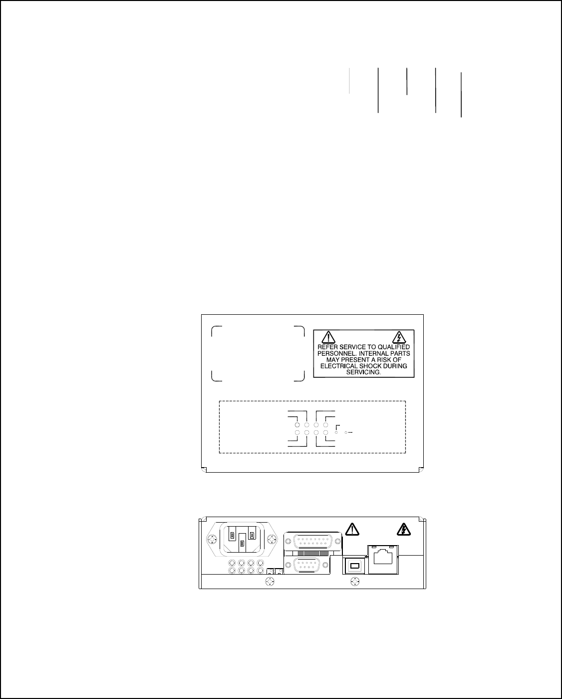
J2 CONTROL I/O
ETHERNET
J4
USB
J5
J3
RS232
J6
HV OUT
TOP COVER
FRONT PANEL
WARNING
OVER VOLTAGE
ARC
REGULATION ERROR
LOCAL CURRENT ADJ
LOCAL VOLT ADJ
STATUS LIGHTS
PWR ON
J1 AC INPUT
OVER TEMPERATURE
OVER CURRENT
CURRENT MODE
HV 0N
Figure 1.1 LED Legend and Connector Assignment
(shown 300W and 600W)
SLM 70 P 600/X(#)
Serie
Nam
Voltag
Maximu
Polarity
"X" Number
Custo
Powe
Maximu
SLM MANUAL 5 118073-001 Rev C
Chapter 2 INSPECTION AND
INSTALLATION
nitial inspection and preliminary checkout procedures
are recommended. For safe operation, please follow
the step-by-step procedures described in Chapter 3,
Operating Instructions.
2.1 Initial Inspection
Inspect the package exterior for evidence of damage due
to handling in transit. Notify the carrier and Spellman
immediately if damage is evident. Do not destroy or
remove any of the packing material used in a damaged
shipment. After unpacking, inspect the panel and chassis
for visible damage.
Fill out and mail the Warranty Registration card
accompanying the unit. Standard SLM high voltage
power supplies and components are covered by warranty.
Custom and special order models (with an X suffix in the
model number) are also covered by warranty.
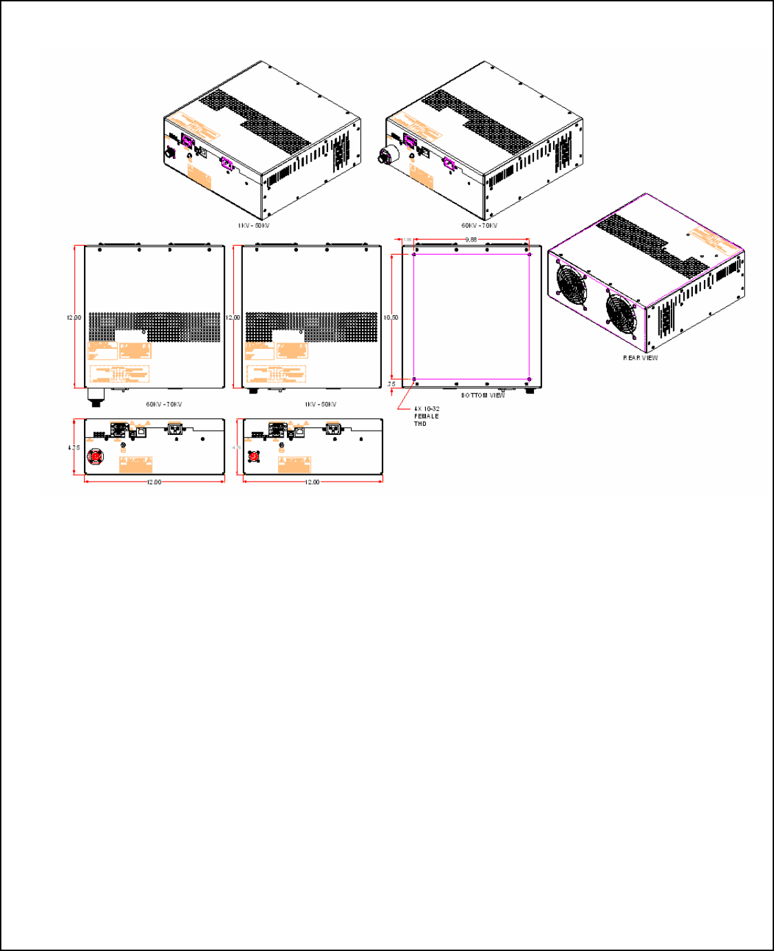
2.2 Mechanical Installation
The SLM series module power supplies are
designed for installation into existing or newly
developed OEM equipment. The power supply
can also easily fit into bench top applications or
test set requirements. Standard unit dimensions
are shown in Figure 2.1
For custom mounting requirements or specific
package size requirements consult Spellman’s
Sales Department. Spellman has many package
designs available, or can design a specific
enclosure for your requirements.
BOTTOM VIEW
1KV - 50KV 60KV - 70KV
1.06 3.88
.75
10.50
4X 10-32 FEMALE THD
12.00 12.00
6.00 6.00
4.75 4.75
Figure 2.1 Unit Dimensions (300W and 600W)
I
SLM MANUAL 6 118073-001 Rev C
Figure 2.2 Unit Dimensions (1200W)

SLM MANUAL 7 118073-001 Rev C
Chapter 3
OPERATING INSTRUCTIONS
3.1 Operation
WARNING
THIS EQUIPMENT GENERATES
DANGEROUS VOLTAGES THAT MAY BE
FATAL. PROPER GROUNDING OF ALL HIGH
VOLTAGE EQUIPMENT IS ESSENTIAL.
IMPORTANT:
Before connecting the power supply to the
AC line, follow this step-by-step procedure.
Do not connect the power supply to the AC
line until Step F is reached.
Failure to follow these procedures may void
the warranty.
A) Insure that the high voltage cable is properly
installed and terminated to the load. Insure that all
circuits connected to the high voltage output are safely
interlocked against accidental contact. Insure external
load is discharged.
B) Check the input voltage rating on the serial
nameplate of the supply and make certain that this is the
rating of the available power source
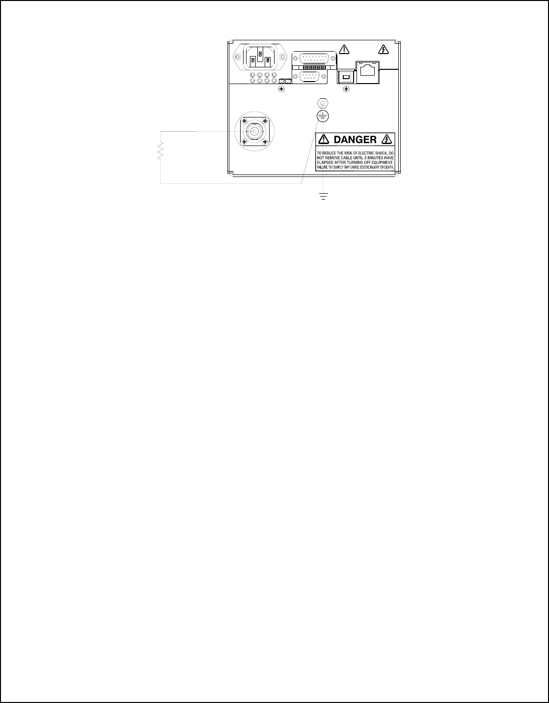
C) PROPER GROUNDING TECHNIQUE: The
chassis of high voltage power supplies must be grounded,
preferably to a water system ground using copper pipe or
other earth ground. A ground stud is provided on the front
panel. See Figure 3.1 for a typical operating setup. The
return line from the load should be connected to the
power supply chassis. Using a separate external ground
at the load is not recommended. An IEC 320 connector is
provided for connection to the line voltage source. A
standard line cord is also provided.
D) Hook-up: Connect control and monitoring
connections as described in this manual.
E) For initial turn-on, program the voltage and
current for zero output. Connect the enable/disable signal
to disable.
F) The input power cable may now be connected to
the AC power line.
G) Enable the power supply via the enable/disable
hardware based, dry contact closure.
H) Slowly program the output voltage and current
to desired level. Monitor the output voltage and current
via the monitoring test points. Note equipment operation
is normal, i.e. load is behaving as predicted.
I) To turn high voltage off, use the enable/disable
signal. If equipment is to be kept off for extended
periods, disconnect power supply from line voltage
source.
WARNING
AFTER TURNOFF, DO NOT HANDLE THE LOAD
UNTIL THE CAPACITANCE HAS BEEN
DISCHARGED!
LOAD CAPACITANCE MAY BE DISCHARGED BY
SHORTING TO GROUND.
WARNING
THE VOLTAGE MONITOR ON THE POWER
SUPPLY FRONT PANEL DOES NOT READ THE
OUTPUT VOLTAGE WHEN THE POWER IS
TURNED OFF, EVEN IF A CHARGE STILL
EXISTS ON THE LOAD.
CAUTION
ALWAYS OPERATE THE UNIT WITH THE COVER
ON. DO NOT ATTEMPT TO ACCESS OR REPAIR
ANY INTERNAL CIRCUITS. DANGEROUS AND
LETHAL VOLTAGES ARE GENERATED INSIDE
THE MODULE.
SLM MANUAL 8 118073-001 Rev C
J2 CONTROL I/O
ETHERNET
J4
USB
J5
OUTPUT
LOAD
OUTPUT RETURN
J3J6
HV OUT
HAZARDOUS VOLTAGE PRESENT
Figure 3.1 Proper Grounding Technique
3.2 Standard Features
A note on remote interface circuitry and remote signal
grounding: whenever possible, electrical isolation should
be provided when interfacing with any high voltage
power supply. For enable/disable signal connections, an
isolated relay or optocoupler should be used. For PS
Fault indication an optocoupler should be used. If
possible, analog programming and monitoring signals
should be isolated via analog isolation amplifiers.
Spellman application engineers are available to assist in
interface circuitry design. All interface cables should be
properly shielded. All power supply signals should be
referenced to the power supplies signal ground or power
supply chassis ground
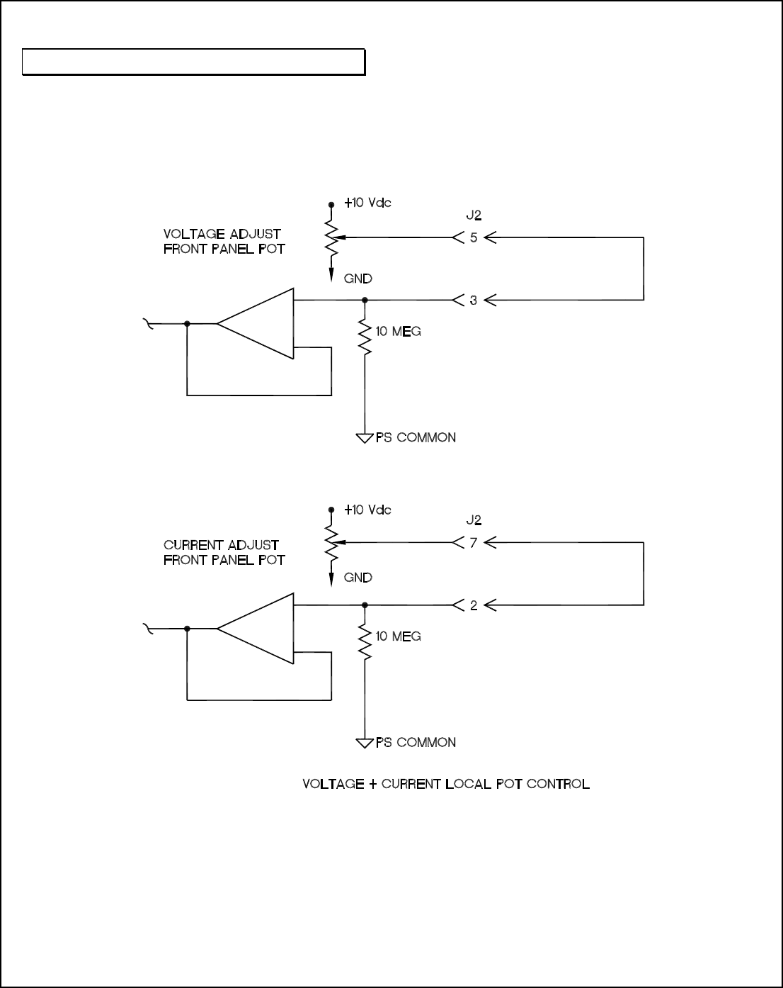
Local Programming potentiometers: The voltage and
current controls on the front panel can be used as follows:
For local current control, jump J2-2 to J2-7. For local
voltage control, jump J2-3 to J2-5. See Figure 3.2.
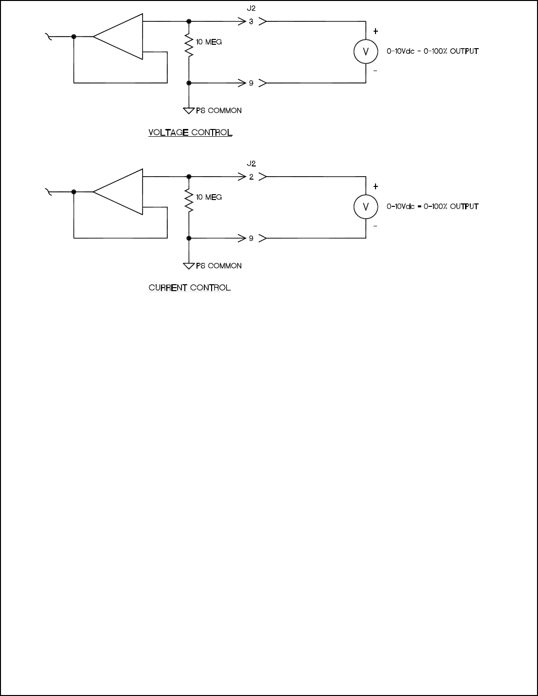
LOCAL PROGRAMMING: Allows local adjustment
of the output voltage and current level via an external
voltage source. 0-10Vdc signal is supplied to pin 3 of the
J2 for voltage programming and 0-10 Vdc signal is
supplied to Pin 2 J2 for current programming.
Programming signals should be referenced to Pin 9 of J2,
signal ground. By adjusting the voltage source from 0
volts (zero output) to 10 Vdc (full rated output) the
desired output can be selected. See Figure 3.3 for wiring
diagram and specifications.
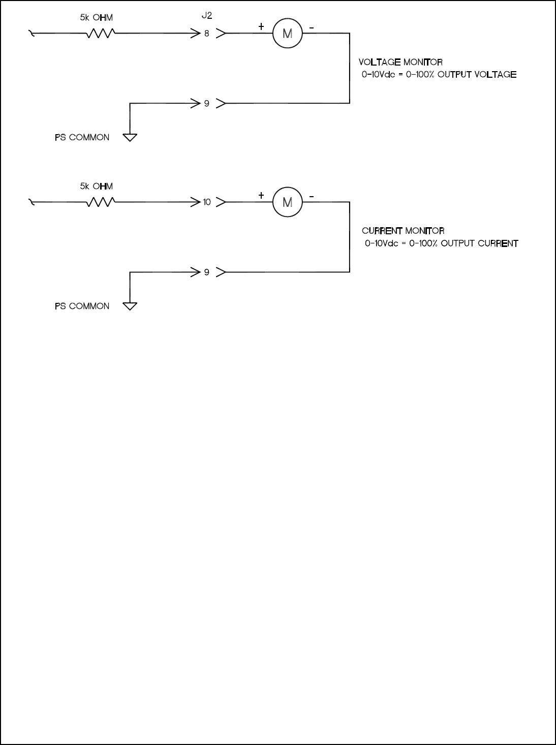
Local Monitoring: Monitor outputs are made available
for monitoring the voltage and current output. The
monitor outputs are always positive regardless of the
output polarity, where zero 0 to 10 Vdc equals 0-100% of
output. See Figure 3.4 for monitoring wiring and see data
sheet for pin outs.
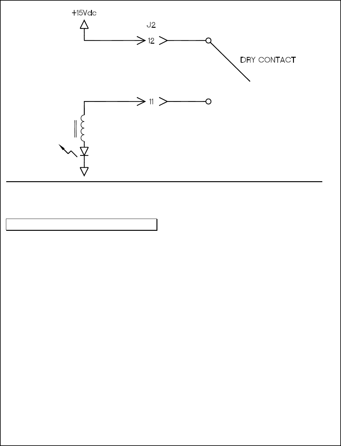
HV Enable/Interlock: In Local Mode allows ON/OFF
control of the high voltage. The hardware based dry
contact closure must be closed in to enable the high
voltage. In Remote Mode this I/O acts as an Interlock.
The hardware based dry contact closure must be closed in
order to enable the high voltage via the USB, Ethernet or
RS232. This can be done by connecting pins 11 and 12
on J2. See Figure 3.5.
REMOTE PROGRAMMING:
After establishing communication with the UUT as per
the SLM Digital Protocol spec. Switch the UUT to Remote
Mode by sending a Program Local/Remote Mode
command (this is done automatically upon opening of the
Spellman GUI/APPLET).If the unit is in Local Mode and
enabled prior to switching it to Remote Mode, the UUT
will shutdown and a P.S Fault indictor will occur when it
is switch to Remote Mode. A clear command can be sent
to clear this fault.
Remote Control: USB, Ethernet and RS232 are standard
Refer to SLM Digital Protocol spec for Details.
Remote Monitor: Allows remote monitoring of the
Output voltage and current via the USB, Ethernet or
RS232.
Remote Programming: Allows remote programming of
the Output voltage and current via the USB, Ethernet or
RS232.
SLM MANUAL 9 118073-001 Rev C
WARNING
It is extremely dangerous to use this
circuit to inhibit high voltage generation
for the purpose of servicing or
approaching any area of load considered
unsafe during normal use.
Figure 3.2 Local Programming Via Internal Front Panel Pot Voltage Source.
SLM MANUAL 10 118073-001 Rev C
Figure 3.3 Local Programming via External Voltage Source
SLM MANUAL 11 118073-001 Rev C
Figure 3.4 Remote Monitoring
SLM MANUAL 12 118073-001 Rev C
RELAY
Figure 3.5 Enable/Interlock Logic Control
WARNING
It is extremely dangerous to use this
circuit to inhibit high voltage generation
for the purpose of servicing or
approaching any area of load considered
unsafe during normal use.

SLM MANUAL 13 118073-001 Rev C
Chapter 4
PRINCIPLES OF OPERATION
he SLM Series of high voltage power supplies
utilizes sophisticated power conversion technology.
Advanced analog and power conversion techniques
are used in the SLM series. The intention of the
Principles of Operation is to introduce the basic function
blocks that comprise the SLM power supply. For details
on a specific circuit, consult Spellman’s Engineering
Department.
The SLM power supply is basically an AC to DC power
converter. Within the power supply, conversions of AC
to DC then to high frequency AC, then to high voltage
DC take place.
Typical SLM power supplies comprise a few basic
building blocks. These are: 1) AC to DC rectifier, 2)
Power Factor correction boost circuitry 3) High frequency
quasi-resonant inverter, 4) High voltage transformer and
rectifier circuits, and 5) Control and monitoring circuits.
The following is a brief description of each building
block.
4.1 Power Factor and Associated
Circuits
The SLM series can operate from 90 - 265Vac, for the
300Watt model and 180 –264Vac for the 600 and
1200Watt models. The input voltage is connected via a
typical IEC 320 type input connector. An internal EMI
filter and fuse housing is an integral part of the SLM
module. The input circuits actively correct the power
factor.
The input line voltage is applied to a current limit device
to reduce the initial inrush current. The input line voltage
is converted to a 400Vdc voltage via an active PFC
Converter.
WARNING
The energy levels used and generated by the
power supply can be lethal! Do not attempt to
operate the power supply unless the user has a
sufficient knowledge of the dangers and hazards
of working with high voltage. Do not attempt to
approach or touch any internal or external
circuits or components that are connected or
have been connected to the power supply. Be
certain to discharge any stored energy that may
be present before and after the power supply is
used. Consult IEEE recommended practices for
safety in high voltage testing #510-1983.
4.2 High Frequency Inverter
The SLM is a resonant converter operating in a zero
current switching, series resonant, parallel loaded
topology. MOSFET transistors switch the 400 Vdc
voltage to the resonant tank circuit. Typical operating
frequency is in the range of 35-65 KHz depending on
model. Control of the resonant circuit output is done by
the low voltage control circuits, and are isolated by an
isolated pulse transformer. The output of the resonant
circuit is applied to the primary of the high voltage
transformer.
4.3 High Voltage Circuits
The high voltage transformer is a step-up type. The
secondary of the high voltage transformer is connected to
the high voltage output circuit. The output circuit will
vary depending upon the rated output voltage and a full
wave Cockroft-Walton multiplier is used. A feedback
signal is generated by the high voltage resistor divider.
This feedback signal is sent to control circuits to provide
voltage regulation and monitoring. A current sense
resistor is connected at the low voltage end of the output
circuit. The circuit sense signal is sent to the control
circuits to provide current regulation and monitoring.
The high voltage output is connected to the output
limiting resistors. These resistors limit the peak surge
current in the event an arc or discharge occurs. The
limiting resistor output is connected to the output
connector provided.
WARNING
THE HVPS IS DESIGNED TO HANDLE AN
ARC RATE OF 1 ARC PER SECOND,
EXCEEDING 1 ARC PER SECOND COULD
CAUSE DAMAGE TO THE HVPS. HVPS
FAILURE CAUSED BY EXCESSIVE ARC
WILL NOT BE COVERED UNDER THE
WARRANTY.
T

SLM MANUAL 14 118073-001 Rev C
4.4 Control Circuits
Control circuits are used for regulation, monitoring,
pulse-width, control, slow-start and inhibit control.
Feedback signals are calibrated and buffered via general
purpose OP-AMPS. Pulse width control is accomplished
by a typical PWM type control I.C. Logic enable/disable
is provided by a logic gate I.C. Regulators generate ±
15Vdc and 10Vdc. DSP based control circuitry provides
excellent regulation, along with outstanding stability
performance
WARNING
LINE VOLTAGE IS PRESENT
WHENEVER THE POWER SUPPLY IS
CONNECTED TO EXTERNAL LINE
VOLTAGES. BE SURE TO DISCONNECT
THE LINE CORD BEFORE OPENING THE
UNIT. ALLOW 5 MINUTES FOR
INTERNAL CAPACITANCE TO
DISCHARGE BEFORE REMOVING ANY
COVER.
4.5 Options
Due to the variations of models and options provided in
the SLM series, details of actual circuits used may differ
slightly from above descriptions. Consult Spellman’s
Engineering Department for questions regarding the
principles of operations for the SLM series.

SLM MANUAL 15 118073-001 Rev C
Chapter 5
5.1 Custom Designed Models X (#)
Units built to customer specifications are assigned an X
number be the factory. If this unit is an X model,
specification control sheet is added at the end of this
instruction manual.
SLM MANUAL 16 118073-001 Rev C
Chapter 6
MAINTENANCE
his section describes periodic servicing and
performance testing procedures.
THIS POWER SUPPLY GENERATES VOLTAGES
THAT ARE DANGEROUS AND MAY BE FATAL.
OBSERVE EXTREME CAUTION WHEN
WORKING WITH HIGH VOLTAGE.
6.1 Periodic Servicing
Approximately once a year (more often in high dust
environments), disconnect the power to the unit. Use
compressed air to blow dust out of the inside of the unit.
Avoid touching or handling the high voltage assembly.
6.2 Performance Test
HIGH VOLTAGE IS DANGEROUS.
ONLY QUALIFIED PERSONNEL SHOULD
PERFORM THESE TESTS.
High voltage test procedures are described in Bulletin
STP-783, Standard Test Procedures for High Voltage
Power Supplies. Copies can be obtained from the
Spellman Customer Service Department. Test equipment,
including an oscilloscope, a high impedance voltmeter,
and a high voltage divider such as the Spellman HVD-
100 is needed for performance tests. All test components
must be rated for operating voltage.
6.3 High Voltage Dividers
High voltage dividers for precise measurements of output
voltage with an accuracy up to 0.1% are available from
Spellman. The HVD-100 is used for voltages up to
100KV. The Spellman divider is designed for use with
differential voltmeters or high impedance digital
voltmeters. The high input impedance is ideal for
measuring high voltage low current sources, which would
be overloaded by traditional lower impedance dividers.
T
WARNING
WARNING

SLM MANUAL 17 118073-001 REV C
Chapter 7
FACTORY SERVICE
7.1 Warranty Repairs
During the Warranty period, Spellman will repair all units
free of charge. The Warranty is void if the unit is worked
on by other than Spellman personnel. See the Warranty
in the rear of this manual for more information. Follow
the return procedures described in Section 7.2. The
customer shall pay for shipping to and from Spellman.
THE SLM HVPS IS DESIGNED TO HANDLE AN
ARC RATE OF 1 ARC PER SECOND. EXCEEDING
1 ARC PER SECOND COULD CAUSE DAMAGE
TO THE HVPS. HVPS FAILURE CAUSED BY
EXCESSIVE ARC WILL NOT BE COVERED
UNDER THE WARRANTY.
7.2 Factory Service Procedures
Spellman has a well-equipped factory repair department.
If a unit is returned to the factory for calibration or repair,
a detailed description of the specific problem should be
attached.
For all units returned for repair, please obtain an
authorization to ship from the Customer Service
Department, either by phone or mail prior to shipping.
When you call, please state the model and serial numbers,
which are on the plate on the rear of the power supply,
and the purchase order number for the repair. A Return
Material Authorization Code Number (RMA Number) is
needed for all returns. This RMA Number should be
marked clearly on the outside of the shipping container.
Packages received without an RMA Number will be
returned to the customer. The Customer shall pay for
shipping to and from Spellman.
A preliminary estimate for repairs will be given by phone
by Customer Service. A purchase order for this amount is
requested upon issuance of the RMA Number. A more
detailed estimate will be made when the power supply is
received at the Spellman Repair Center. In the event that
repair work is extensive, Spellman will call to seek
additional authorization from your company before
completing the repairs.
7.3 Ordering Options and
Modifications
Many of the options listed in Chapter 5 can be retrofitted
into Spellman power supplies by our factory. For prices
and arrangements, contact our Sales Department.
7.4 Shipping Instructions
All power supplies returned to Spellman must be sent
shipping prepaid. Pack the units carefully and securely in
a suitable container, preferably in the original container, if
available. The power supply should be surrounded by at
least four inches of shock absorbing material. Please
return all associated materials, i.e. high voltage output
cables, interconnection cables, etc., so that we can
examine and test the entire system.
All correspondence and phone calls should be directed to:
Spellman High Voltage Electronics Corp.
475 Wireless Boulevard
Hauppauge, New York 11788
TEL: (631) 630-3000 FAX: (631) 435-1620
E-Mail: sales@Spellmanhv.com
http://www.spellmanhv.com

101520-007 REV D
SPELLMAN HIGH VOLTAGE ELECTRONICS
WARRANTY
Spellman High Voltage Electronics (“Spellman”) warrants that all power supplies it manufactures will be
free from defects in materials and factory workmanship, and agrees to repair or replace, without charge, any
power supply that under normal use, operating conditions and maintenance reveals during the warranty
period a defect in materials or factory workmanship. The warranty period is twelve (12) months from the
date of shipment of the power supply. With respect to standard SL power supplies (not customized) the
warranty period is thirty-six (36) months from the date of shipment of the power supply.
This warranty does not apply to any power supply that has been:
• Disassembled, altered, tampered, repaired or worked on by persons unauthorized by Spellman;
• subjected to misuse, negligent handling, or accident not caused by the power supply;
• installed, connected, adjusted, or used other than in accordance with the original intended application and/or
instructions furnished by Spellman.
THE FOREGOING WARRANTY IS IN LIEU OF ALL OTHER WARRANTIES, EXPRESS OR IMPLIED, INCLUDING
THOSE OF MERCHANTABILITY OR FITNESS FOR A PARTICULAR PURPOSE.
The buyer’s sole remedy for a claimed breach of this warranty, and Spellman’s sole liability is limited, at
Spellman’s discretion, to a refund of the purchase price or the repair or replacement of the power supply at
Spellman’s cost. The buyer will be responsible for shipping charges to and from Spellman’s plant. The
buyer will not be entitled to make claim for, or recover, any anticipatory profits, or incidental, special or
consequential damages resulting from, or in any way relating to, an alleged breach of this warranty.
No modification, amendment, supplement, addition, or other variation of this warranty will be binding unless
it is set forth in a written instrument signed by an authorized officer of Spellman.
Factory Service Procedures
For an authorization to ship contact Spellman’s Customer Service Department. Please state the model and
serial numbers, which are on the plate on the rear panel of the power supply and the reason for return. A
Return Material Authorization Code Number (RMA number) is needed from Spellman for all returns. The
RMA number should be marked clearly on the outside of the shipping container. Packages received without
an RMA Number may delay return of the product. The buyer shall pay shipping costs to and from Spellman.
Customer Service will provide the Standard Cost for out-of-warranty repairs. A purchase order for this
amount is requested upon issuance of the RMA Number (in-warranty returns must also be accompanied by
a “zero-value” purchase order). A more detailed estimate may be made when the power supply is received
at Spellman. In the event that the cost of the actual repair exceeds the estimate, Spellman will contact the
customer to authorize the repair.
Factory Service Warranty
Spellman will warrant for three (3) months or balance of product warranty, whichever is longer, the repaired
assembly/part/unit. If the same problem shall occur within this warranty period Spellman shall undertake all
the work to rectify the problem with no charge and/or cost to the buyer. Should the cause of the problem be
proven to have a source different from the one that has caused the previous problem and/or negligence of
the buyer, Spellman will be entitled to be paid for the repair.
Spellman Worldwide Service Centers
For a complete listing of Spellman’s Global Service facilities please go to:
http://www.spellmanhv.com/customerservice/service.asp
SLM Digital Interface
Manual
Ethernet
Serial – RS-232
Universal Serial Bus - USB
Copyright © 2007, Spellman High Voltage Electronics Corporation. All Rights Reserved.
This information contained in this publication is derived in part from proprietary and patent data. This information has
been prepared for the express purpose of assisting operating and maintenance personnel in the efficient use of the
model described herein, and publication of this information does not convey any right to reproduce it or to use it for
any purpose other than in connection with installation, operation, and maintenance of the equipment described.
475 Wireless Boulevard • Hauppauge, New York 11788, USA • www.spellmanhv.com • T:+1 631.630.3000 • F:+1 631.435.1620
118080-001 REV A
Table Of Contents
1.0 Scope ....................................................................................................................... 3
2.0 Functional Description ........................................................................................... 3
3.0 Getting Started - Interface Wiring and Pin-outs ................................................... 3
3.1 RS232 Interface .................................................................................................................... 3
3.2 Ethernet Interface.................................................................................................................. 5
3.3 Universal Serial Bus Interface..............................................................................................6
3.4 RS-232 Cabling..................................................................................................................... 6
3.5 Ethernet Cabling ................................................................................................................... 6
3.6 USB Cabling......................................................................................................................... 8
4.0 Getting Started - Software.................................................................................... 10
4.1 RS-232 ................................................................................................................................ 10
4.2 Ethernet............................................................................................................................... 12
4.3 USB..................................................................................................................................... 29
5.0 Ethernet Commands ............................................................................................. 37
5.1 TCP/IP Format.................................................................................................................... 37
5.2 Command Arguments ......................................................................................................... 38
5.3 Command Overview........................................................................................................... 38
5.4 Response Overview ............................................................................................................ 40
5.5 Command Structure ............................................................................................................ 41
6.0 Serial Commands – RS-232 / USB ....................................................................... 67
6.1 Serial Interface Protocol ..................................................................................................... 67
6.2 Command Arguments ......................................................................................................... 67
6.3 Checksums.......................................................................................................................... 67
6.4 Command Overview........................................................................................................... 69
6.5 Response Overview ............................................................................................................ 70
6.6 Command Structure ............................................................................................................ 72
6.7 Spellman Test Commands .................................................................................................. 95
6.8 Serial Command Handling.................................................................................................. 95
118080-001 REV A Page 2 of 95
WARNING
THIS EQUIPMENT GENERATES DANGEROUS VOLTAGES THAT MAY BE FATAL.
PROPER GROUNDING OF ALL HIGH VOLTAGE EQUIPMENT IS ESSENTIAL.SEE SLM
OWNERS MANUAL FOR PROPER GROUNDING TECHNIQUE AND SAFETY
PRECAUTIONS BEFORE APPLING AC INPUT POWER TO THE SLM UNIT.
TO PREVENT DAMAGE TO THE HOST COMPUTER ,THE COMPUTER SHOULD BE
GROUNDED TO THE UNIT.
1.0 SCOPE
This document applies to the communications interfaces on the SLM, assembly
460067.
2.0 FUNCTIONAL DESCRIPTION
The SLM provides 3 different types of digital communications interfaces:
• RS-232 on J3
• Ethernet (10/100-Base-T) on J5
• Universal Serial Bus on J4.
3.0 GETTING STARTED - INTERFACE WIRING AND PIN-OUTS
3.1 RS232 INTERFACE
The RS232C interface has the following attributes:
• 115K bits per second
• No Parity
• 8 Data Bits
• 1 Stop Bit
• No handshaking
• DB-9 connector as shown
118080-001 REV A Page 3 of 95

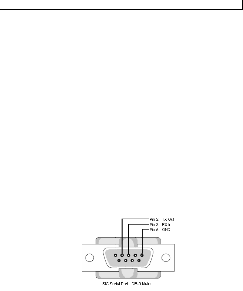
Figure 1 – J3, RS-232 DB-9M pinout (front view)
PIN DESCRIPTION
1 -
2 Tx Out
3 Rx In
4 -
5 Ground
6 -
7 -
8 -
9 -
118080-001 REV A Page 4 of 95
3.2 ETHERNET INTERFACE
The Ethernet interface has the following attributes:
• 10/100-Base-T
• IP address can be set by the system integrator
• Network Mask can be set by the system integrator
• TCP Port Number can be set by the system integrator
• RJ-45 connector
• Network attachment via Crossover and Standard Ethernet cables.
• Supported Operating Systems: Windows 98 2ED, Windows 2000
(SP2), Windows NT (SP6), Windows XP Professional
LED 2 LED 1
8 7 6 5 4 3 2 1
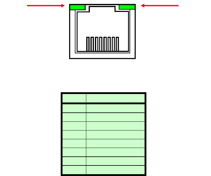
Figure 2 – J5, Ethernet RJ45 Jack (front view)
PIN DESCRIPTION
1 TX+
2 TX-
3 RX+
4 -
5 -
6 RX-
7 -
8 -
The Ethernet RJ-45 has two LED indicators, as shown in Figure 2. The left
LED, LED1 indicates that the network processor has a valid network link.
The right LED, LED2 indicates network activity.
118080-001 REV A Page 5 of 95
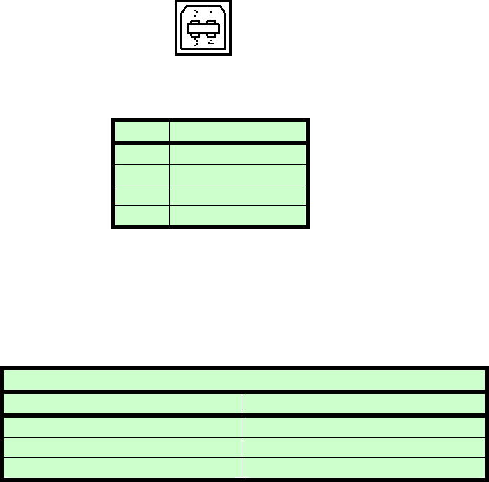
3.3 USB – UNIVERSAL SERIAL BUS INTERFACE
The USB interface has the following attributes:
• Compliant with USB 1.1 and USB 2.0 specifications
• Type B male connector
• Included driver can be communicated with via standard Windows
serial communications methods
Figure 3 – J4, USB Type B (front view)
PIN DESCRIPTION
1 Vbus +5V
2 D-
3 D+
4 Ground
3.4 RS-232 CABLING
A standard shielded RS-232 cable is used to connect the SLM serial port
to the serial port on a standard personal computer. Please refer to the
following chart.
PC to SLM Board Cable Details
PC Connector (DB-9 Female) SLM Connector (DB-9 Male)
Pin 2: RX In Pin 2: TX Out
Pin 3: TX Out Pin 3: RX In
Pin 5: Ground Pin 5: Ground
3.5 ETHERNET CABLING
Shielded Category 5 (CAT5) Ethernet patch cables are used to connect
the SLM to the host computer. There are two ways to connect to the SLM
board via Ethernet: the first is to directly cable between the host and the
SLM board, and the second is through the use of a switch, hub, or
network.
118080-001 REV A Page 6 of 95
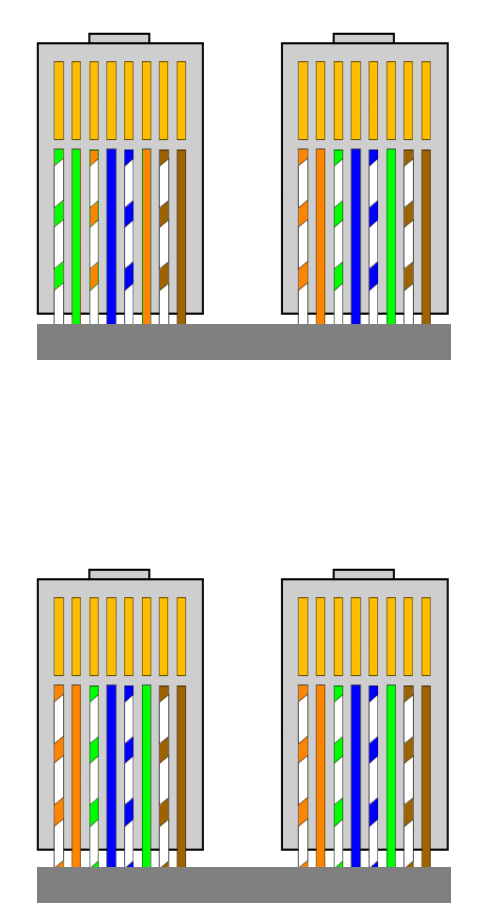
A direct connection requires a non-standard cable where the wires are not
run straight through. Please refer to the two cable ends shown below in
figure 4.
Figure 4 – Crossover Cable for Direct Connection
A standard connection through a hub, switch, or network uses a standard
CAT5 patch cable. Please refer to the two cable ends shown below in
figure 5.
Figure 5 – Standard Straight Through Cable – Standard CAT5 Patch
1
1
1
1
118080-001 REV A Page 7 of 95
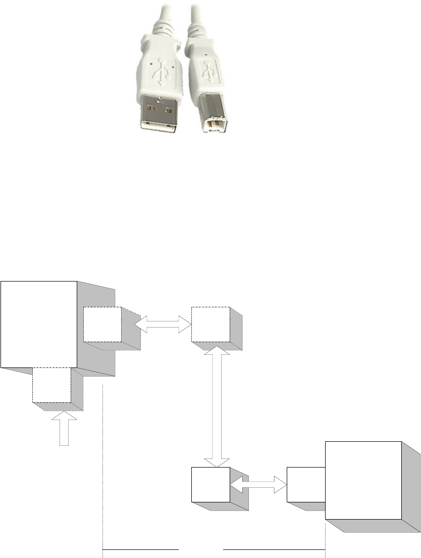
3.6 USB CABLING
A high-quality double-shielded USB 2.0 Type A to B (host to slave) cable
should be used in all applications. This type of cable is a standard PC to
peripheral cable that utilizes full-size connectors.
Figure 6 – USB A-to-B cable
3.6.1 HIGH EMI ENVIRONMENTS
If the SLM USB interface is being used in a high-EMI environment, ferrites
should be added to the USB cable. Figure 7 illustrates the possible
combinations of ferrites that can be used to achieve acceptable operation
under these conditions.
POW ER SUPPLY
WITH
USB
FERRITE
BEAD
(cable)
FERRITE
BEAD
(cable)
PC
WITH
USB
FERRITE
CORE
(cable)
FERRITE
CORE
(cable)
USB CABLE
FERRITE
CORE
(cable)
24 V DC
Figure 7 – Block Diagram of USB Cable Utilizing Ferrites
118080-001 REV A Page 8 of 95
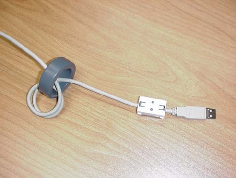
Ferrite beads should be attached to the USB cable next to the connectors
– both sides should be installed. In extreme cases ferrite cores may be
added where the cable is looped 3 or 4 times around the core as shown in
figure 8. Cores of 1.5 to 2 inches should be used at both ends of the
cable.
Figure 8 - Example of a USB Cable Using Ferrites
Please refer to the USB Interface Setup section, for an explanation of how
USB works and why EMI may present a problem for this communications
interface.
118080-001 REV A Page 9 of 95
4.0 GETTING STARTED – SOFTWARE
The following sections detail how to create software to interface to the SLM
communications interfaces.
4.1 RS-232
The RS-232 interface makes use of a standard ‘command/response’
communications protocol. See section 6.0 for the syntax of the serial
interface protocol. The programmer should also review section 4.3 for
programming considerations for the USB interface as the code is nearly
identical for the RS-232 interface.
All software that addresses the RS-232 interface must adhere to the
following parameters:
• A default Baud rate of 115.2K bps
• No Parity
• 8 Data Bits
• 1 Stop Bit
• No handshaking
The Baud rate can be changed to 115.2K ,57.6k,38.4k,19.2k or 9600 bps
and stored in the unit.
4.1.1 Enabling Communications Objects in Visual Basic for RS-232
Communications in Microsoft Visual Basic 6.0 are directed to a control
that abstracts the port. In the case of serial and USB we need
Microsoft Comm Control 6.0. To enable this in your VB 6 project, go to:
Project -> Components
Then in the list make sure that Microsoft Comm Control 6.0 has a
check next to it. The Comm Control Object should then appear in your
toolbox. It will have an icon of a telephone and will be named:
MSComm. This can be dragged and dropped into your application.
You will then need to set the object’s properties.
4.1.2 Configuring Communications in Visual Basic for RS-232
In order to configure the MSComm Object, first you must initialize it
in the Object properties:
Settings 115200,n,8,1
Handshaking 0 – comNone
The application can be set to either default to a specific COM Port
or the End User can be allowed to choose one for the particular PC.
118080-001 REV A Page 10 of 95
For the “Default” scenario, include the following commands in the
Form_Load() routine:
MSComm1.CommPort = portNumber
MSComm1.PortOpen = True
For the “Choice” scenario, place the above two commands in a
selectable menu item.
118080-001 REV A Page 11 of 95
4.2 ETHERNET
The SLM contains an embedded diagnostic web server that can be
accessed through any standard web browser by browsing to the SLM’s IP
address. For example:
http://192.168.1.4
The Ethernet interface communicates using the following protocols:
• TCP/IP
• HTTP
• TFTP
• FTP
4.2.1 Diagnostic Web Server
The diagnostic web server can control and monitor an SLM equipped
power supply from a web browser. It displays operating status of the
Power Supply and allows the unit to be configured in real time. The
application consists of three web pages; a page displaying contact
information, a license agreement, and a monitoring and control applet that
is at the heart of this application. The Web Server application for the SLM
is presented as an example in the following pages.
4.2.2 Web Pages
4.2.2.1 Web Page 1: Contact Information Page
Figure 9 displays a picture of the SLM and information on how to
contact Spellman High Voltage Electronics Corporation. By clicking
on the picture of the SLM or on the button labeled “Click Here to
Monitor and Control” one can move on to the next screen, the
license agreement.
118080-001 REV A Page 12 of 95
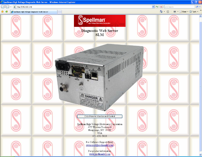
Figure 9 - Web Page 1- Contact Information
118080-001 REV A Page 13 of 95
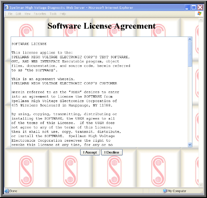
4.2.2.2 Web Page 2: License Agreement Page
Figure 10 displays the license agreement. Here the user can either
agree or disagree with the Spellman license agreement. Click on “I
Accept” to continue on to the applet.
Figure 10 - Web Page 2 – License Agreement
118080-001 REV A Page 14 of 95
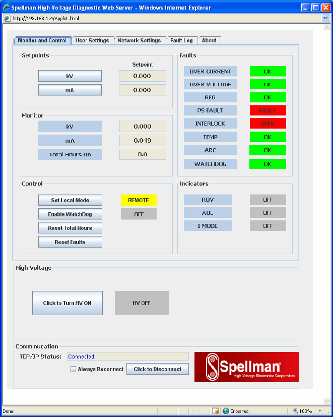
4.2.2.3 Web Page 3 - Monitor and Control Applet
4.2.2.3.1 Requirements
The Monitor and Control Applet is a java “applet” (“small java
application” specifically written to be embedded in a web
page and invoked from a browser) that requires an Internet
browser with an installed JVM (Java Virtual Machine). The
password for the applet is: shvapplet. We have tested
under Internet Explorer 5 and 6, Microsoft JVM 5 and Sun
JVM versions 1.6 and higher.
4.2.2.3.2 Description of Monitor and Control Applet
Figure 11 displays an example of an embedded monitor and
control application.
Figure 11 - Control and Monitor Applet
118080-001 REV A Page 15 of 95
View the screen as a “left” and a “right” with the right half
containing status read from the SLM and the left half
containing the values that are programmable by the user.
For any programmable setting you click on the button to the
left of the setting, which brings up the program set point
screen. For example, click on the button labeled, ‘V’ to set
the output voltage set point. Refer to figure 12.
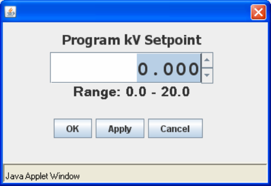
4.2.2.4 Program Set Point Screen
.
Figure 12 - Program Configurable Values Screen
The field is the scaled value or real world value. Enter the desired
set point level within the shown range.
The user can then click Apply to send the set point to the SLM and
remain in the set point screen, or click OK to send the set point and
close the set point entry window. The user may also click on
Cancel to close the window without sending any changes.
To reset the Total hour On meter to zero via the Applet a password
is required.The password is “SHV_Reset”
4.2.2.5 Java Warning Messages
You may notice a message at the bottom of all dialog windows that
are displayed from the SLM Control and Monitor Applet. The
wording may vary slightly depending on the JVM version but on
some the message is “Java Applet Window”. This message informs
the user that the dialog window was generated by an applet. The
design philosophy for the JVM was for secure computing, so the
origins of new windows are supposed to be as obvious as possible.
118080-001 REV A Page 16 of 95
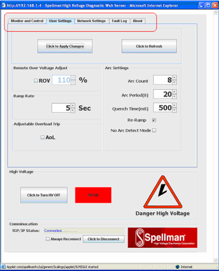
4.2.2.6 “Tabs” on Applet
The user can view and set operating parameters of the applet or
network configurations of the SLM or view firmware version
information by changing tabs.
4.2.2.7 User Settings
Figure 13 – User Setting
The User Settings tab allows the user to set firmware configurable
options, as shown above. After making changes to the options,
click on the “Click to Apply Changes” button.
118080-001 REV A Page 17 of 95
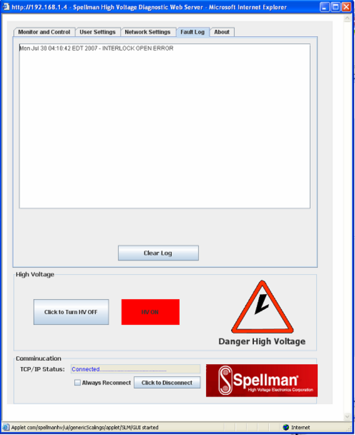
4.2.2.8 Fault log
Figure 14 – Fault log
Fault log displays faults with their date and time.
118080-001 REV A Page 18 of 95
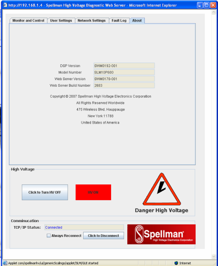
4.2.2.9 About
Displays version information and model number.
Figure 15 – About
118080-001 REV A Page 19 of 95

4.2.2.10 Turning the SLM HVOn/Off and Connection Status
Please refer to Figure 11, the Monitor and Control Applet.
Setting Name Range Values
Local/Remote Local mode/Remote mode
HV On/Off
Interlock Open/Closed
Fault Status OK/Fault
Connection Status Connected/No Data Received/Disconnected
Unlike the controls we previously discussed at the top of the screen
which required a separate dialog screen to enter values, these are
controlled by a button. For example, an On/Off button controls the
HV. When HV is on, the Control is labeled “Click to Turn HV Off”.
When HV is off, the control is labeled “Click to Turn HV On”.
Thereby handling the two distinct states.
Notice that at the very bottom of the screen is a text field that
displays the current connection status, which as mentioned above
is one of three values. “Connected” is displayed when there exists a
valid TCP/IP session connecting the SLM and the Applet and data
is being received by the applet from the SLM. The next state is “No
Data Received” which is when there is still a valid connection but no
responses have been received from the SLM for 2 seconds. Lastly,
the text field displays “Disconnected” when the TCP/IP session has
been disconnected. To operate the UUT using the Computer
interface the UUT must be set to Remote Mode by Clicking “Click to
Set Remote, the SLM Applet automatically sets the unit to Remote
mode upon connecting.
When the Applet is first started and anytime the “Click To Connect”
button is clicked there is a 5 second delay as the Applet starts up
the threads necessary for communication between it and the SLM.
4.2.3 Direct Connection between the SLM and a Computer
A direct Ethernet connection between the SLM and the computer
requires an RJ45 crossover cable. The end connectors will look
identical to a “normal” RJ45 connector but the colors of some of the
wires in the connectors will be “reversed”. Hold up the two ends of
the RJ45 cable and look at the color of the wires from left to right.
They should differ on the two connectors.
118080-001 REV A Page 20 of 95

When direct connecting the SLM to a computer using a crossover
cable over Ethernet they are essentially participating in a private
network. As such you need to pick two valid IP addresses, one for
each device.
The table below illustrates that not all IP addresses are actually
valid IP addresses. For example, IP addresses beginning with 127
are not valid.
Class Address Range
A 1.0.0.0-126.255.255.255
B 128.0.0.0-191.255.255.255
C 192.0.0.0-223.255.255.255
4.2.3.1 Configuring the Computer for Direct Ethernet
Connection
As mentioned above both the IP Address and Subnet Mask need to
be configured. In our environment computers normally are assigned
IP addresses dynamically, using DHCP. We need to change this
and assign the IP Address statically to the one we have selected.
Here are the steps on Windows XP. On the desktop right click on
“My Network Places” and select properties at the bottom of the
menu.
Figure 16 – Right Click on Desktop
118080-001 REV A Page 21 of 95
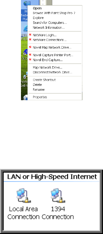
Figure 17 – Select Properties
After selecting properties you are brought up to the screen below
(Figure 18). You must RIGHT CLICK and select Properties on
Local Area Connection, and not double click which will display a
window similar to figure 19.
Figure 18 – Here you must Right Click and Select Properties
118080-001 REV A Page 22 of 95
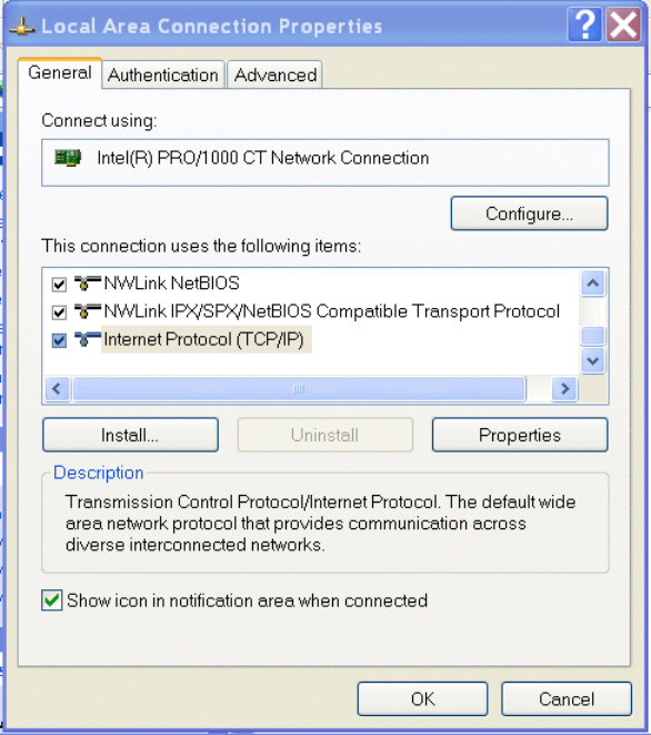
Figure 19 – Local Area Connection Properties
Now you must select “Internet Protocol (TCP/IP)” and click on the
Properties button to be brought to figure 20. Lastly you must
disable any firewall software you have running. If you are running a
proxy server for Internet access, you must also disable the proxy
client. Disabling this also requires a reboot.
118080-001 REV A Page 23 of 95
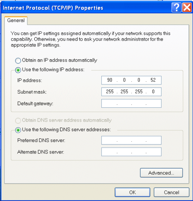
Figure 20 – TCP/IP Properties
4.2.3.2 Testing a Direct Connection
You can use the program “Ping” to test a network connection
between the computer and the SLM. “Ping” is a command line tool
so we will need to bring up a command prompt. Under Windows
NT, 2000 and XP the name of this command is “CMD”. Under
Windows 98 the name of this command is “Command”.
To do this, click on Start->Run->Cmd
Then on the command line type
Ping <IP Address>
For example
Ping 192.168.1.4
If the SLM is found at the specified IP address, the Ping command
will respond with a report that is similar to:
Pinging 192.168.1.4 with 32 bytes of data:
118080-001 REV A Page 24 of 95
Reply from 192.168.1.4: bytes=32 time<1ms TTL=64
Reply from 192.168.1.4: bytes=32 time<1ms TTL=64
Reply from 192.168.1.4: bytes=32 time<1ms TTL=64
Reply from 192.168.1.4: bytes=32 time<1ms TTL=64
Ping statistics for 192.168.1.4:
Packets: Sent = 4, Received = 4, Lost = 0 (0% loss),
Approximate round trip times in milli-seconds:
Minimum = 0ms, Maximum = 0ms, Average = 0ms
4.2.4 Configuring the SLM For a Local Area Network (LAN)
If you have chosen to place the SLM onto your local area network
you will need:
• A CAT5 network patch cable to physically connect the SLM
to the LAN
• A static IP address to assign to the SLM.
Remember that even if the IP address you have selected is in
general a valid IP address it needs to be valid for your LAN (local
area network). Otherwise the device will not be accessible from an
Internet browser or Ping.
4.2.4.1 Configuring the Network Settings from the
Monitor and Configure Applet
The network settings are configurable from the Network Settings
tab, refer to figure 21.
118080-001 REV A Page 25 of 95
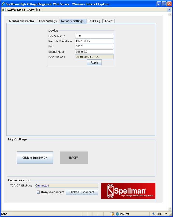
Figure 21 - Configure Network Settings
The settings that can be changed are the:
• Device Name
• IP Address
• TCP Port
• Subnet Mask
Once the Apply button is clicked on the network settings screen,
the network component of the SLM is configured, rebooted and the
applet is disconnected from the SLM. You must type the NEW IP
address into a web browser to bring up a new instance of the applet
to monitor and control the SLM after reconfiguring it. This may also
118080-001 REV A Page 26 of 95
require reconfiguring the host computer with the correct host IP
address, subnet mask, and TCP port.
The device name does not affect the operation of the SLM; it is
simply a way for the user to differentiate multiple units on the same
network.
Depending on the type of network you are attaching the SLM to,
you may need to configure the host PC’s IP address and subnet
mask as shown in section 4.2.3.1. You can also test a network
connection to the SLM by following the instructions listed in section
4.2.3.2 .
4.2.5 Enabling Communications Objects in Visual Basic for Ethernet
Communications
For Ethernet communications, we need Microsoft Winsock Control 6.0 and
SP5. To enable this in your VB 6 project, go to:
Project -> Components
Once selected in your toolbox, you will have an icon of two computers
linked together and will be named: Winsock. This can be dragged and
dropped into your application. Then set the object’s properties.
4.2.6 Configuring Communications in Visual Basic for Ethernet
In order to configure the Winsock Object, you must make the following
initialization in the object’s properties:
Protocol 0 – sckTCPProtocol
Then, in the application code, include the following commands:
tcpClient.RemoteHost = host
tcpClient.RemotePort = portNumber
tcpClient.Connect
For further information regarding the use of the above commands, please
refer to your Visual Studio Help File.
4.2.6.1 Data Output Example
MSComm1 is both the serial and USB port. TcpClient is the
Ethernet port.
118080-001 REV A Page 27 of 95
If (portType = "ethernet") Then
tcpClient.SendData (str)
Else
MSComm1.InBufferCount = 0
On Error GoTo done
MSComm1.Output = str
done:
tmrOpenClose.Enabled = True
End If
4.2.6.2 Data Input Example
If (portType = "ethernet") Then
Do
DoEvents
.............................................................................................................................
..................................................................................................ttcpClient.GetData temp$
str = str + temp$
Loop Until InStr(str, Chr(3)) Or Timer - t1 > 1
On Error Resume Next
Else
Do
DoEvents
If MSComm1.InBufferCount > 0 Then
str = str & MSComm1.Input
End If
Loop Until InStr(str, Chr(3)) Or Timer - t1 > 1
If InStr(str, Chr(3)) > 0 Then
tmrOpenClose.Enabled = False
End If
End If
118080-001 REV A Page 28 of 95
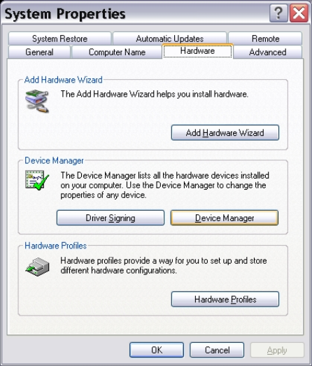
4.3 USB
The USB interface makes use of a standard ‘command/response’
communications protocol. See section 6.0 for the syntax of the serial
interface protocol.
The USB interface is accessed through a Windows USB Human Interface
driver (HID).
4.3.1 USB Driver Installation
The HID driver is a Windows driver installed with the operating system. To
determine if the driver had been acquired open the System properties
window selecting the Control Panel System Properties.
Figure 22 – System Properties
Then select Device Manager and expand the Human Interface Devices.
View the properties of the USB Human Interface Device icon and verify
that Spellman USB HID appears in the Location section.
118080-001 REV A Page 29 of 95
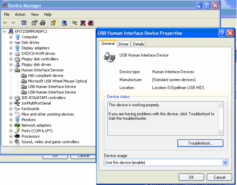
Figure 23 – Device Manager showing USB HID
4.3.2 USB and EMI
The USB protocol utilizes a heartbeat signal from each client device back
to the host (PC). If the heartbeat is interrupted due to radiated or
conducted transient noise, it is possible that the host may lose connection
with the client. This can cause problems with data transfers over the USB
cable.
The DXM when used in combination with the HID Windows driver makes it
possible for the host to renumerate the client connection and reestablish
communications. This is providing the control application implements a
method of timeout and retry.
NOTE: If an EMI disruption occurrs the DXM will continue to renumerate
until a connection with the GUI is re-established.
118080-001 REV A Page 30 of 95
4.3.3 Enabling Communications Objects in Visual Basic for USB
The dynamic link library USB_dll.dll will be provided which needs to be
added to the project. The library has three functions that can be called
from the VB code.
The three functions are:
• FindTheHid – finds the connection with the correct VID, PID and Serial
Number
• WriteReport(str) – Writes a string to the connected HID interface
• ReadReport() – Returns a string from the connected HID interface
4.3.4 Configuring Communications in Visual Basic for USB
To use the USB_dll.dll in VB the following statements are needed.
Dim usb As usbDll
Dim MyDeviceDetected As Boolean
Set usb = New usbDll
Using this statement determines whether a connection is present.
MyDeviceDetected = usb.FindTheHid
If MyDeviceDetected is true then the connection is present.
4.3.5 Software Considerations for USB Reconnection
The following Visual Basic code snippets are presented as a guideline for
implementation with revision C and higher assemblies.
4.3.5.1 Recognize partial, corrupt, or absent data
1: temp2$ = inputInputString
2: If temp2$ <> "" Then
3: btn_UPDATEDATA.Value = False
4: CommStatusFlag = True
5: CommaPos = InStr(Start, temp2$, Comma, vbTextCompare)
6: ' Channel 0
7: On Error GoTo endhere
8: AmbTemp = Mid(temp2$, Start, (CommaPos - Start))
Please note that even though we have guarded against no data, in
line 2, we still need to guard against bad data, in this case no
comma, on line 8. If there is no comma, we wind up passing a
negative value to Mid, which is an error, that we should trap for.
118080-001 REV A Page 31 of 95
4.3.5.2 Retrieve data only if it exists
1: Do
2: DoEvents
3: If MSComm1.InBufferCount > 0 Then
4: str = str & MSComm1.Input
5: End If
6: Loop Until InStr(str, Chr(3)) Or Timer - t1 > 1
7: 'str = str & MSComm1.Input
8: If InStr(str, Chr(3)) > 0 Then
9: tmrOpenClose.Enabled = False
10: End If
Notice that in line 3 we check for the existence of data before we
extract data from the USB port. Normally, if there is no data, line 4
would append an empty string. However, during a noise event,
retrieving data without first checking the existence of data could
hang.
4.3.5.3 Example Output Routine
Notice that on line 13 we register an error handler in case the port
is invalid because we have closed it in another routine. Notice that
on line 16 we start a timer. When we output data on the port we
start a timer to keep track of incoming data. If we get no incoming
data it means that communications have been interrupted.
1: Private Sub outputOutputString(outputString As String)
2: Dim str As String
3: str = ProcessOutputString(outputString)
4: StatusBar1.Panels(4).Text = "TX: " & str
5: 'StatusBar1.Panels(3).Text = "RX: Waiting"
6: If (portType = "ethernet") Then
7: tcpClient.SendData (str)
8: ElseIf (portType = "USB") Then
9: usb.WriteReport (str)
10: Else
11: MSComm1.InBufferCount = 0
12:
13: On Error GoTo done
14: MSComm1.Output = str
15: done:
16: tmrOpenClose.Enabled = True
17: End If
18: End Sub
118080-001 REV A Page 32 of 95
4.3.5.4 Example Input Routine
Notice on line 26 we check for data first before extracting data from
the input. Then if we have actual data we turn off the timer.
Otherwise the timer routine toggles the port open/close.
1: Private Function inputInputString() As String
2: Dim str As String
3: Dim t1 As Single
4: Dim temp$
5: Dim stra As String
6: Dim stri(300) As String
7: t1 = Timer
8:
9: If (portType = "ethernet") Then
10: Do
11: DoEvents
12: tcpClient.GetData temp$
13: str = str + temp$
14: Loop Until InStr(str, Chr(3)) Or Timer - t1 > 1
15: On Error Resume Next
16: ElseIf (portType = "USB") Then
17: Do
18: DoEvents
19: stra = usb.ReadReport
20: str = str & stra
21: 'str = str & ReadReport
22: Loop Until InStr(str, Asc(3)) Or Timer - t1 > 0.09
23: Else
24: Do
25: DoEvents
26: If MSComm1.InBufferCount > 0 Then
27: str = str & MSComm1.Input
28: End If
29: Loop Until InStr(str, Chr(3)) Or Timer - t1 > 1
30:
31: If InStr(str, Chr(3)) > 0 Then
32: tmrOpenClose.Enabled = False
33: End If
34:
35: frm_EXTRAS.txt_MSCOMMBUFF.Text = str
36: tmr_COMMWDT.Enabled = True
37: On Error Resume Next
118080-001 REV A Page 33 of 95
38: End If
39: StatusBar1.Panels(3).Text = "RX: " & str
40: inputInputString = str
41: tmr_RCVTIMER.Enabled = True
42: End Function
4.3.5.5 Example Timer Routine: Toggle Port State
This is the timer routine in which the open/closed state of the port is
toggled. If communications are interrupted, the USB device will re-
register itself with the OS (vendor term: renumeration). Once this
happens, re-opening the port will enable communications. Until the
re-registration happens, open operations will fail. Notice line 5
where we register an error handler.
1:Private Sub tmrOpenClose_Timer()
2: If MSComm1.PortOpen = True Then
3:
4: MSComm1.PortOpen = False
5: On Error GoTo done
6: MSComm1.PortOpen = True
7: done:
8: tmrOpenClose.Enabled = False
9: End If
10:
11: End Sub
4.3.5.6 Example Timer Routine: Port Reconnection
This is another timer routine whose purpose is to turn the port on if
it is off. Notice that in line 8 an error handler is called because if the
device has not re-registered itself with the OS, an error will be
raised.
1: Private Sub tmr_COMMWDT_Timer()
2:
3: tmr_COMMWDT.Enabled = False
4:
5: If CommStatusFlag = True Then
6:
7: If MSComm1.PortOpen = False Then
8: On Error GoTo done
9: MSComm1.PortOpen = True
10: done:
11: End If
12:
13: ElseIf CommStatusFlag = False Then
14:
118080-001 REV A Page 34 of 95
15: If MSComm1.PortOpen = False Then
16:
17: MSComm1.PortOpen = True
18: Else
19: MSComm1.PortOpen = False
20: End If
21:
22: End If
4.3.5.7 Data Parsing Example
Here we have an example of a code that parses incoming data.
Notice that it makes use of our generic input and output routines.
The important consideration is to gracefully handle corrupted input
data after a noise event. In this case we may get data, so a test
against empty string returns false, but we may not get commas in
the correct place. Notice that we register an error handler on line 26
so that the mid function, which would raise an error when given a
negative number, is handled.
1: Private Sub btn_EMI_Click()
2: Dim temp2$
3: Dim Response1$
4: Dim Response2$
5: Dim number$
6: Dim Comma
7: Dim CommaPos
8: Dim Start
9: Dim ODATA$
10:
11: Comma = ","
12: Start = 5
13:
14: If tmr_RCVTIMER.Enabled = True Then
tmr_RCVTIMER.Enabled = False
15: If tmr_NETRCVTMR.Enabled = True Then
tmr_NETRCVTMR.Enabled = False
16:
17: If AutoUpdate = True Then
18: tmr_UPDATE.Enabled = False
19: End If
20:
21: number$ = "15,"
22: outputOutputString (number$)
23:
24: temp2$ = inputInputString
25: CommaPos = InStr(Start, temp2$, Comma, vbTextCompare)
118080-001 REV A Page 35 of 95
26: On Error GoTo endhere
27: Response1$ = Mid(temp2$, Start, (CommaPos - Start))
28:
29: 'With a 5v reference:
30: ODATA$ = Format(str(Response1$ * 0.0004884), "0.##0")
31:
32: txt_DACB.Text = ODATA$ + " mA"
33: frm_RAWDATA.txt_RAWDACB.Text = str(Response1$)
34: txt_DACB.BackColor = vbWhite
35: CommStatusFlag = True
36: endhere:
37:
38: If portType = "ethernet" Then
39: tmr_NETRCVTMR.Enabled = True
40: Else
41: tmr_RCVTIMER.Enabled = True
42: End If
43:
44: If AutoUpdate = True Then tmr_UPDATE.Enabled = True
46: End Sub
118080-001 REV A Page 36 of 95

5.0 ETHERNET COMMANDS
5.1 TCP/IP FORMAT
Each Ethernet command will consist of a TCP/IP header followed by the required
data bytes. Figure 27 summarizes the TCP/IP header configuration. Please note
that this functionality is provided by the software implementation of the Open
Systems Interconnection (OSI) TCP/IP protocol stack, specifically the upper 4
layers.
Byte
0 Protocol
Version Header
Length
Type Of
Service Total Length
4 Packet ID
Flags Fragmentation Offset
8 Time To Live
Protocol Header checksum
12 Source Address
16 Destination Address
20 Source Port
Destination Port
24 Sequence Number
28 Acknowledgement Number
32 Data
Offset Reserved Code Bits
Window
36 Checksum
Urgent Pointer
40 Data Byte 1
Data Byte 2 Data Byte 3 Data Byte N
Figure 24: Network TCP/IP datagram header
118080-001 REV A Page 37 of 95

The format of Data Bytes 1 through N are as follows:
<STX><CMD><,>ARG><,><ETX>
Where:
<STX> = 1 ASCII 0x02 Start of Text character
<CMD> = 2 ASCII characters representing the command ID
<,> = 1 ASCII 0x2C character
<ARG> = Command Argument
<,> = 1 ASCII 0x2C character
<ETX> = 1 ASCII 0x03 End of Text character
5.2 COMMAND ARGUMENTS
The format of the numbers is a variable length string. To represent the number
42, the string ‘42’, ‘042’, or ‘0042’ can be used. This being the case, commands
and responses that carry data are variable in length.
5.3 COMMAND OVERVIEW
Data Byte section of the TCP/IP Datagram
Command Name <CMD> <ARG> RANGE
Program RS-232
unit baud rate 07 1 ASCII 1 - 5
Program User
Configs 09 9 ASCII See
Description
Program kV 10 1-4 ASCII 0-4095
Program mA 11 1-4 ASCII 0-4095
Request kV
Setpoint 14 None -
Request mA
Setpoint 15 None -
Request Analog
Monitor Readbacks 19 None -
Request HV On
Hours Counter 21 None -
Request Status 22 None -
Request Software
Version 23 None -
Request Hardware
Version 24 None -
Request Web
Server Version 25 None -
Request Model
Number 26 None -
118080-001 REV A Page 38 of 95

Request User
Configs 27 None
Request unit
Scaling 28 None
Reset HV On
Hours Counter 30 None -
Reset Faults 31 None -
Request Network
Settings 50 None -
Program Network
Settings 51 6 ASCII See
Description
Read Interlock
Status 55 1 ASCII 0 or 1
Request kV
monitor 60 None -
Request mA
monitor 61 None -
Request –15V
LVPS 65 None -
Watchdog Tickle 88 None -
Watchdog enable 89 1 ASCII 0 or 1
Turn HV on/off 98 1 ASCII 0 or 1
Program
Local/Remote
Mode
99 1 ASCII 0 or 1
118080-001 REV A Page 39 of 95

5.4 RESPONSE OVERVIEW
The command responses will follow the same network TCP/IP header format as
outlined above in section 5.1. This list is comprised of Commands with complex
responses only. Commands using a simple response will use the <$> character
(ASCII 0x24) as a “Success” response or a single character error code. These
will be seven ASCII characters in length.
Response Name <CMD> Response
Request kV
Setpoint 14 7-10
ASCII
Request mA
Setpoint 15 7-10
ASCII
Request Analog
Monitor
Readbacks
19 11-22
ASCII
Request Total
Hours High
Voltage On
21 13 ASCII
Request Status 22 12 ASCII
Request DSP
Software Version 23 17 ASCII
Request Hardware
Version 24 9 ASCII
Request Web
Server Version 25 17 ASCII
Request Model
number 26 11 ASCII
Request User
Configs 27 8-16 ASCII
Request unit
Scaling 28 23-31
ASCII
Request Network
Settings 50 48-104
ASCII
Read Interlock
Status 55 7 ASCII
Request kV
monitor 60 7-10
ASCII
Request mA
monitor 61 7-10
ASCII
Request –15V
LVPS 65 7-10
ASCII
Request Faults 68 19 ASCII
118080-001 REV A Page 40 of 95

5.5 COMMAND STRUCTURE
5.5.1 Program kV
Description:
The host requests that the firmware change the setpoint of kV.
Direction:
Host to supply
Syntax:
<STX><10><,><ARG><,><ETX>
Where:
<ARG> = 0 - 4095 in ASCII format
Example:
<STX>10,4095,<ETX>
Response:
<STX><10><,><$><,><ETX>
<STX><10><,><ARG><,><ETX>
where <ARG> = error code
Error Codes TBD, 1 = out of range
118080-001 REV A Page 41 of 95

5.5.2 Program mA
Description:
The host requests that the firmware change the setpoint of mA.
Direction:
Host to supply
Syntax:
<STX><11><,><ARG><,><ETX>
Where:
<ARG> = 0 - 4095 in ASCII format
Example:
<STX>11,4095,<ETX>
Response:
<STX><11><,><$><,><ETX>
<STX><11><,><ARG><,><ETX>
where <ARG> = error code
Error Codes TBD, 1 = out of range
118080-001 REV A Page 42 of 95

5.5.3 Request Total Hours High Voltage On
Description:
The host requests that the firmware sends the present value of the Total
Hours High Voltage On.
Direction:
Host to supply
Syntax:
<STX><21><,><ETX>
Example:
<STX>21,<ETX>
Response:
<STX><21><,><ARG1>< ARG2>< ARG3><ARG4><ARG5>
<.><ARG6><,><ETX>
Where:
<.> = ASCII 0x2E
ARGx =0-9 in ASCII format
Example:
<STX>21,99999.9,<ETX>
118080-001 REV A Page 43 of 95

5.5.4 Request Status
Description:
The host requests that the firmware sends the power supply status.
Direction:
Host to supply
Syntax:
<STX><22><,><ETX>
Example:
<STX>22,<ETX>
Response:
<STX><22><,><ARG1><,><ARG2><,><ARG3><,><ARG4><,><ARG5><,
><ARG6><,><ARG7><,><ARG8><,<ETX>
Where:
<ARG1> 1 = HvOn, 0 = HvOff
<ARG2> 1 = Interlock 1 Open, 0 = Interlock 1 Closed
<ARG3> 1 = Fault Condition, 0 = No Fault
<ARG4> 1 = Remote Mode, 0 = Local Mode
<ARG5> 1 = I Mode on, 0 = = I Mode off
<ARG6> 1 = ROV Enabled, 0 = ROV Disabled
<ARG7> 1 = AOL Enabled, 0 = AOL Disabled
<ARG8> 1 = Watchdog Enabled, 0 = Watchdog Disabled
Example:
<STX>22,1,1,0,0,0,0,0,0,<ETX>
118080-001 REV A Page 44 of 95

5.5.5 Request DSP Software Part Number/Version
Description:
The host requests that the firmware sends the DSP firmware version.
Direction:
Host to supply
Syntax:
<STX><23><,><ETX>
Example:
<STX>23,<STX>
Response:
<STX><23><,>< ARG><,><ETX>
Where:
<ARG> consists of eleven ASCII characters representing the current
firmware part number/version. The format is SWM9999-999
Example:
<STX>23,SWM9999-999,<ETX>
118080-001 REV A Page 45 of 95

5.5.6 Request Hardware Version
Description:
The host requests that the firmware sends the hardware version.
Direction:
Host to supply
Syntax:
<STX><24><,><ETX>
Example:
<STX>24,<ETX>
Response:
<STX><24><,>< ARG><,><ETX>
Where:
<ARG> consists of 3 ASCII characters representing the hardware version.
The format is ANN, where A is an alpha character and N is a numeric
character
Example:
<STX>24,A01,<ETX>
118080-001 REV A Page 46 of 95

5.5.7 Request Webserver Software Part Number/Version
Description:
The host requests that the firmware sends the Web Server firmware part
number/version.
Direction:
Host to supply
Syntax:
<STX><25><,><ETX>
Example:
<STX>25,<ETX>
Response:
<STX><25><,><ARG><,><ETX>
Where:
<ARG> consists of eleven ASCII characters representing the current
firmware part number/version. The format is SWM9999-999
Example:
<STX>25,SWM9999-999,<ETX>
118080-001 REV A Page 47 of 95

5.5.8 Request Model Number
Description:
The host requests that the firmware sends the unit model number
Direction:
Host to supply
Syntax:
<STX><26><,><ETX>
Example:
<STX>26,<ETX>
Response:
<STX><26><,><ARG><,><ETX>
Where:
<ARG> consists of five ASCII characters representing the model number.
The format is SLMNNANNN or XNNNN, where N is a numeric character
and where A is a letter character.
Example:
<STX>25,SLM70P600,<ETX> or <STX>25,X9999,<ETX>
118080-001 REV A Page 48 of 95

5.5.9 Reset Run Hours
Description:
The host requests that the firmware resets the run hour counter.
Direction:
Host to supply
Syntax:
<STX><30><,><ETX>
Example:
<STX>30,<ETX>
Response:
<STX><30><,><$><,><ETX>
118080-001 REV A Page 49 of 95

5.5.10 Reset Faults
Description:
The host requests that the firmware resets all Fault messages and
indicators.
Direction:
Host to supply
Syntax:
<STX><31><,><ETX>
Example:
<STX>31,<ETX>
Response:
<STX><31><,><$><,><ETX>
118080-001 REV A Page 50 of 95
5.5.11 Request Network Settings
Description:
The host requests that the firmware transmits the network settings
Application:
ARG 1 ARG2 ARG3 ARG4 ARG5
Function Device
Name Remote
Address Remote
Port Subnet
Mask MAC
Address
Direction:
Host to supply
Syntax:
<STX><50><,><ETX>
Example:
<STX>50,<ETX>
Response:
<STX><50><,><ARG1><,><ARG2><,><ARG3><,><ARG4><,>
<ARG5><,><,><ETX>
Arguments:
Device Name is limited to 20 characters or less. Remote address is a ip
address in dotted notation. Remote port is a decimal number. Subnet
Mask and Default Gateway are also dotted notation and MAC address is
in MAC Address notation.
ARG1: Device Name 1 character minimum, up to 20 maximum
ARG2: IP Address <nnn><.><nnn><.><nnn><.><nnn>, where
<nnn> represents a number from 0 to 255.
ARG3: Remote Port 5001 or from 49152 to 65535.
ARG4: Subnet Mask <xxx><.><xxx><.><xxx><.><xxx>, where
<xxx> represents a number from 0 to 255.
ARG5: MACAddress <zzz><:><zzz><:><zzz><:><zzz><:><zzz>
<:><zzz> , where <zzz> represents a number
from 0 to 255.
Example:
<STX>50,Spellman2.0,32.78.110.37,1026,255.0.0.0,0:100:33:1:32:84,<E
TX>
118080-001 REV A Page 51 of 95

5.5.12 Program Network Settings
Description:
The host requests that the firmware programs the network settings and
then reboots.
Application:
ARG 1 ARG2 ARG3 ARG4 ARG5
Function Device
Name Remote
Address Remote
Port Subnet
Mask MAC
Address
Direction:
Host to supply
Syntax:
<STX><51><,><ARG1><,><ARG2><,><ARG3><,><ARG4><,>
<ARG5><,><ARG6><,><ETX>
Arguments:
Device Name is limited to 20 characters or less. Remote address is a ip
address in dotted notation. Remote port is a decimal number. Subnet
Mask and Default Gateway are also dotted notation and MAC address is
in MAC Address notation.
ARG1: Device Name 1 character minimum, up to 20 maximum
ARG2: IP Address <nnn><.><nnn><.><nnn><.><nnn>, where
<nnn> represents a number from 0 to 255.
ARG3: Remote Port 5001 or from 49152 to 65535.
ARG4: Subnet Mask <xxx><.><xxx><.><xxx><.><xxx>, where
<xxx> represents a number from 0 to 255.
ARG5: MACAddress <zzz><:><zzz><:><zzz><:><zzz><:><zzz>
<:><zzz> , where <zzz> represents a number
from 0 to 255.
Example:
<STX>51,Spellman2.0,32.78.110.37,1026,255.0.0.0,0:100:33:1:32:84,<E
TX>
Response:
None, as Embedded server reboots with new settings.
118080-001 REV A Page 52 of 95

5.5.13 Read Interlock Status
Description:
The host requests that the firmware read the status of the interlock
channel.
Direction:
Host to supply
Syntax:
<STX><55><,><ETX>
Response:
<STX><55><,><ARG1><,><ETX>
Where ARG1 is Interlocks 1. A 1 indicates that the Interlock is energized
Example:
<STX>55,1,<ETX>
118080-001 REV A Page 53 of 95

5.5.14 Request kV Monitor
Description:
The host requests that the firmware report kV monitor.
Direction:
Host to supply
Syntax:
<STX><60><,><ETX>
Response:
<STX><60><,><ARG><,><ETX>
Where:
<ARG>=0-4095 in ASCII format representing unscaled value.
Example:
<STX>60,4095,<ETX>
118080-001 REV A Page 54 of 95

5.5.15 Request mA Monitor
Description:
The host requests that the firmware report mA monitor.
Direction:
Host to supply
Syntax:
<STX><61><,><ETX>
Response:
<STX><61><,><ARG><,><ETX>
Where:
<ARG>=0-4095 in ASCII format representing unscaled value.
Example:
<STX>61,4095,<ETX>
118080-001 REV A Page 55 of 95

5.5.16 Request –15V LVPS
Description:
The host requests that the firmware report –15V LVPS.
Direction:
Host to supply
Syntax:
<STX><65><,><ETX>
Response:
<STX><65><,><ARG><,><ETX>
Where:
<ARG>=0-4095 in ASCII format representing unscaled value.
Example:
<STX>65,4095,<ETX>
118080-001 REV A Page 56 of 95

5.5.17 Request Faults
Description:
The host requests that the firmware report Faults.
Direction:
Host to supply
Syntax:
<STX><68><,><ETX>
Response:
<STX><68><,><ARG1><,><ARG2><,><ARG3><,><ARG4><,><ARG5><,
><ARG6><,><ARG7><,><ETX>
Where:
<ARGx> 1 = Fault, 0 = No Fault in ASCII format
ARG1 = ARC
ARG2 = Over Temperature
ARG3 = Over Voltage
ARG4 = Under Voltage
ARG5 = Over Current
ARG6 = Under Current
ARG7 = Watchdog
Example:
<STX>68,0,0,0,0,1,0,0,<ETX>
118080-001 REV A Page 57 of 95

5.5.18 Turn HV on/off
Description:
The host requests that the firmware turn high voltage on or high voltage
off.
Direction:
Host to supply
Syntax:
<STX><98><,><ARG><,><ETX>
Where:
<ARG> 1 = HV on, 0 = HV off in ASCII format
Example:
<STX>98,1,<ETX>
Response:
<STX><98><,><$><,><ETX>
<STX><98><,><ARG><,><ETX>
where <ARG> = error code
Error Codes TBD,
1 = out of range
118080-001 REV A Page 58 of 95

5.5.19 Program Local/Remote Mode
Description:
The host requests that the firmware to switch between Local and Remote
Mode.
Direction:
Host to supply
Syntax:
<STX><99><,><ARG><,><ETX>
Where:
<ARG> 1 = Remote, 0 = Local in ASCII format
Example:
<STX>99,1,<ETX>
Response:
<STX><99><,><$><,><ETX>
<STX><99><,><ARG><,><ETX>
where <ARG> = error code
Error Codes TBD,
1 = out of range
118080-001 REV A Page 59 of 95

5.5.20 Program RS-232 Baud rate
Description:
The host requests that the firmware change the Baud rate for RS-232.
Direction:
Host to supply
Syntax:
<STX><07><,><ARG><,><ETX>
Where:
<ARG> 1 = 9.6k in ASCII format
<ARG> 2 = 19.2k in ASCII format
<ARG> 3 = 38.4k in ASCII format
<ARG> 4 = 57.6k in ASCII format
<ARG> 5 = 15.2k in ASCII format
Example:
<STX>07,1,<ETX>
Response:
<STX><07><,><$><,><ETX>
<STX><07><,><ARG><,><ETX>
where <ARG> = error code
Error Codes TBD,
1 = out of range
118080-001 REV A Page 60 of 95

5.5.22 Program User Configs
Description:
The host requests that the firmware program the user configs.
Direction:
Host to supply
Syntax:
<STX><09><,><ARG1><,><ARG2><,><ARG3><,><ARG4><,><ARG5><,
><ARG6><,><ARG7><,><ARG8><,><ARG9><,><ETX>
Where:
<ARG1> = 1 = ROV enabled, 0 = ROV disabled in ASCII format.
<ARG2> = 0-110 in ASCII format representing the overvoltage
percentage.
<ARG3> = 1-600 in ASCII format representing the ramp rate in seconds
from .1 to 60sec.
<ARG4> = 1 = AOL enabled, 0 = AOL disabled in ASCII format.value.
<ARG5> = 0-20 in ASCII format representing the arc count.
<ARG6> = 0-60 in ASCII format representing the arc period in seconds.
<ARG7> = 0-500 in ASCII format representing the arc quench time in milli-
seconds.
<ARG8> = 1 = ARC re-ramp enabled, 0 = ARC re-ramp disabled in
ASCII format.
<ARG9> = 1 = No Arc detect, 0 = Arc detect in ASCII format.
Example:
<STX>09,1,50,100,0,10,30,250,1,0,<ETX>
Response:
<STX><09><,><$><,><ETX>
<STX><09><,><ARG><,><ETX>
where <ARG> = error code
Error Codes
1 in ASCII format = Invalid Arc Rate warning message:
An invalid arc rate(Time period/Arc Count) of more than 1 arc per second has
been entered,these values along with the other variables in the command string
have been disregarded by the HVPS.
2 in ASCII format = NAD Enabled warning message:
The Not Arc Detect mode has been enabled. In this mode the HVPS has no Arc
shutdown protection. The HVPS is designed to handle 1 arc per second.
Exceeding 1 arc per second could cause damage to the HVPS.HVPS failure
caused by excessive arcing will not be covered under the warranty.
118080-001 REV A Page 61 of 95

5.5.23 Request unit Scaling
Description:
The host requests that the firmware report the unit scaling.
Direction:
Host to supply
Syntax:
<STX><28><,><ETX>
Example:
<STX>28,<ETX>
Response:
<STX><28><,>< ARG1><,>< ARG2><,><ETX>
Where:
<ARG1> =0-65535 in ASCII format representing the voltage full-scale
value.
<ARG2> =0-65535 in ASCII format representing the current full-scale
value.
Example:
<STX>28, 7000, 856<ETX>
Voltage full scale = 70.00kV
Current full scale = 8.56mA
118080-001 REV A Page 62 of 95

5.5.24 Request User Configs
Description:
The host requests that the firmware report the User Configs.
Direction:
Host to supply
Syntax:
<STX><27><,><ETX>
Example:
<STX>27,<ETX>
Response:
<STX><27><,><ARG1><,><ARG2><,><ARG3><,><ARG4><,><ARG5><,
><ARG6><,><ARG7><,><ARG8><,><ARG9><,><ETX>
Where:
<ARG1> = 1 = ROV enabled, 0 = ROV disabled in ASCII format.
<ARG2> = 0-110 in ASCII format representing the overvoltage
percentage.
<ARG3> = 1-600 in ASCII format representing the ramp rate in seconds
from .1 to 60sec.
<ARG4> = 1 = AOL enabled, 0 = AOL disabled in ASCII format.value.
<ARG5> = 0-20 in ASCII format representing the arc count.
<ARG6> = 0-60 in ASCII format representing the arc period in seconds.
<ARG7> = 0-500 in ASCII format representing the arc quench time in milli-
seconds.
<ARG8> = 1 = ARC re-ramp enabled, 0 = ARC re-ramp disabled in
ASCII format.
<ARG9> = 1 = No Arc detect, 0 = Arc detect in ASCII format.
Example:
<STX>27,1,50,100,0,10,30,250,1,0,<ETX>
118080-001 REV A Page 63 of 95

5.5.25 Watchdog Enable
Description:
The host requests that the firmware enable the Communication Watchdog.
Direction:
Host to supply
Syntax:
<STX><89><,><ARG><,><ETX>
Where:
<ARG> 1 = enable, 0 = disable in ASCII format
Example:
<STX>89,1,<ETX>
Response:
<STX><89><,><$><,><ETX>
<STX><89><,><ARG><,><ETX>
where <ARG> = error code
118080-001 REV A Page 64 of 95

5.5.26 Watchdog Tickle
Description:
The host requests that the firmware resets the Watchdog timer.
Direction:
Host to supply
Syntax:
<STX><88><,><ETX>
Response:
<STX><88><,><$><,><ETX>
<STX><88><,><ARG><,><ETX>
where <ARG> = error code
118080-001 REV A Page 65 of 95

5.5.27 Request Analog Monitor Readbacks
Description:
The host requests that the firmware transmit the present values of Analog
Monitor Readbacks.
Direction:
Host to supply
Syntax:
<STX><19><,><ETX>
Example:
<STX><19>,<ETX>
Response:
<STX><19><,><ARG1><,><ARG2><,><ARG3><,><ETX>
Where:
ARG1 = kV monitor = 0 – 4095
ARG2 = mA monitor = 0 – 4095
ARG3 = unused = 0– 4095
Example:
<STX><19>,4095,4095,4095,<ETX>
118080-001 REV A Page 66 of 95
6.0 SERIAL COMMANDS – RS-232 / USB
6.1 SERIAL INTERFACE PROTOCOL
Serial communications will use the following protocol:
<STX><CMD><,>ARG><,><CSUM><ETX>
Where:
<STX> = 1 ASCII 0x02 Start of Text character
<CMD> = 2 ASCII characters representing the command ID
<,> = 1 ASCII 0x2C character
<ARG> = Command Argument
<,> = 1 ASCII 0x2C character
<CSUM> = Checksum (see section 6.3 for details)
<ETX> = 1 ASCII 0x03 End of Text character
6.2 COMMAND ARGUMENTS
The format of the numbers is a variable length string. To represent the number
42, the string ‘42’, ‘042’, or ‘0042’ can be used. This being the case, commands
and responses that carry data are variable in length.
6.3 CHECKSUMS
The checksum is computed as follows:
• Add the <CMD>, <,>, and <ARG> bytes into a 16 bit (or larger) word.
The bytes are added as unsigned integers.
• Take the 2’s compliment (negate it).
• Truncate the result down to the eight least significant bits.
• Clear the most significant bit (bit 7) of the resultant byte, (bitwise AND with
0x7F).
• Set the next most significant bit (bit 6) of the resultant byte (bitwise OR
with 0x40).
Using this method, the checksum is always a number between 0x40 and 0x7F.
The checksum can never be confused with the <STX> or <ETX> control
characters, since these have non-overlapping ASCII values.
If the DSP detects a checksum error, the received message is ignored – no
acknowledge or data is sent back to the host. A timeout will act as an implied
NACK.
118080-001 REV A Page 67 of 95
The following is sample code, written in Visual Basic, for the generation of
checksums:
Public Function ProcessOutputString(outputString As String) As String
Dim i As Integer
Dim CSb1 As Integer
Dim CSb2 As Integer
Dim CSb3 As Integer
Dim CSb$
Dim X
X = 0
For i = 1 To (Len(outputString)) 'Starting with the CMD character
X = X + Asc(Mid(outputString, i, 1)) 'adds ascii values together
Next i
CSb1 = 256 - X
CSb2 = 127 And (CSb1) 'Twos Complement
CSb3 = 64 Or (CSb2) 'OR 0x40
CSb$ = Chr(Val("&H" & (Hex(CSb3))))
ProcessOutputString = Chr(2) & outputString & CSb$ & Chr(3)
End Function
118080-001 REV A Page 68 of 95

6.4 COMMAND OVERVIEW
Data Byte section of the TCP/IP Datagram
Command Name <CMD> <ARG> RANGE
Program RS-232
unit baud rate 07 1 ASCII 1 - 5
Program User
Configs 09 9 ASCII See
Description
Program kV 10 1-4 ASCII 0-4095
Program mA 11 1-4 ASCII 0-4095
Request kV
Setpoint 14 None -
Request mA
Setpoint 15 None -
Request Analog
Monitor
Readbacks
19 None -
Request HV On
Hours Counter 21 None -
Request Status 22 None -
Request Software
Version 23 None -
Request Hardware
Version 24 None -
Request Web
Server Version 25 None -
Request Model
Number 26 None -
Reset HV On
Hours Counter 30 None -
Reset Faults 31 None -
Read Interlock
Status 55 None -
Request kV
monitor 60 None -
Request mA
monitor 61 None -
Request –15V
LVPS 65 None -
Wathdog Tickle 88 None -
Wathdog enable 89 1 ASCII 0 or 1
Turn HV on/off 98 1 ASCII 0 or 1
118080-001 REV A Page 69 of 95

Program
Local/Remote
Mode
99 1 ASCII 0 or 1
6.5 RESPONSE OVERVIEW
The command responses will follow the same format as outlined above in
section 6.1. This list is comprised of Commands with complex responses
only. Commands using a simple response will use the <$> character
(ASCII 0x24) as a “Success” response or a single character error code.
These responses will be eight ASCII characters in length.
Response Name <CMD> Response
Request kV
Setpoint 14 8-11 ASCII
Request mA
Setpoint 15 8-11 ASCII
Request Analog
Monitor
Readbacks
19 12-23
ASCII
Request Total
Hours High
Voltage On
21 14 ASCII
Request Status 22 13 ASCII
Request DSP
Software Version 23 18 ASCII
Request Hardware
Version 24 10 ASCII
Request Web
Server Version 25 18 ASCII
Request Model
number 26 12 ASCII
Request User
Configs 27 9-17 ASCII
Request unit
Scaling 28 24-32
ASCII
Read Interlock
Status 55 8 ASCII
Request kV
monitor 60 8-11
ASCII
Request mA
monitor 61 8-11
ASCII
Request –15V
LVPS 65 8-11
ASCII
118080-001 REV A Page 70 of 95

Request Faults 68 20 ASCII
118080-001 REV A Page 71 of 95

6.6 COMMAND STRUCTURE
6.6.1 Program kV
Description:
The host requests that the firmware change the setpoint of kV.
Direction:
Host to supply
Syntax:
<STX><10><,><ARG><,><CSUM><ETX>
Where:
<ARG> = 0 - 4095 in ASCII format
Example:
<STX>10,4095,<CSUM><ETX>
Response:
<STX><10><,><$><,><CSUM><ETX>
<STX><10><,><ARG><,><CSUM><ETX>
where <ARG> = error code
Error Codes TBD, 1=out of range
118080-001 REV A Page 72 of 95

6.6.2 Program mA
Description:
The host requests that the firmware change the setpoint of mA.
Direction:
Host to supply
Syntax:
<STX><11><,><ARG><,><CSUM><ETX>
Where:
<ARG> = 0 - 4095 in ASCII format
Example:
<STX>11,4095,<CSUM><ETX>
Response:
<STX><11><,><$><,><CSUM><ETX>
<STX><11><,><ARG><,><CSUM><ETX>
where <ARG> = error code
Error Codes TBD, 1=out of range
118080-001 REV A Page 73 of 95

6.6.3 Request Total Hours High Voltage On
Description:
The host requests that the firmware sends the present value of the Total
Hours High Voltage On.
Direction:
Host to supply
Syntax:
<STX><21><,><CSUM><ETX>
Example:
<STX>21,<CSUM><ETX>
Response:
<STX><21><,><ARG1>< ARG2>< ARG3><ARG4><ARG5>
<.><ARG6><,><CSUM><ETX>
Where:
<.> = ASCII 0x2E
ARGx = 0 - 9 in ASCII format
Example:
<STX>21,99999.9,<CSUM><ETX>
118080-001 REV A Page 74 of 95

6.6.4 Request Status
Description:
The host requests that the firmware sends the power supply status.
Direction:
Host to supply
Syntax:
<STX><22><,><CSUM><ETX>
Example:
<STX>22,<CSUM><ETX>
Response:
<STX><22><,><ARG1><,><ARG2><,><ARG3><,><ARG4><,><ARG5><,
><ARG6><,><ARG7><,><ARG8><,><CSUM><ETX>
Where:
<ARG1> 1 = HvOn, 0 = HvOff
<ARG2> 1 = Interlock 1 Open, 0 = Interlock 1 Closed
<ARG3> 1 = Fault Condition, 0 = No Fault
<ARG4> 1 = Remote Mode, 0 = Local Mode
<ARG5> 1 = I Mode on, 0 = = I Mode off
<ARG6> 1 = ROV Enabled, 0 = ROV Disabled
<ARG7> 1 = AOL Enabled, 0 = AOL Disabled
<ARG8> 1 = Watchdog Enabled, 0 = Watchdog Disabled
Example:
<STX>22,1,1,0,0,0,0,0,0,<CSUM><ETX>
118080-001 REV A Page 75 of 95

6.6.5 Request DSP Software Part Number/Version
Description:
The host requests that the firmware sends the DSP firmware version.
Direction:
Host to supply
Syntax:
<STX><23><,><CSUM><ETX>
Example:
<STX>23,<CSUM><STX>
Response:
<STX><23><,>< ARG><,><CSUM><ETX>
Where:
<ARG> consists of eleven ASCII characters representing the current
firmware part number/version. The format is SWM9999-999
Example:
<STX>23,SWM9999-999,<CSUM><ETX>
118080-001 REV A Page 76 of 95

6.6.6 Request Hardware Version
Description:
The host requests that the firmware sends the hardware version.
Direction:
Host to supply
Syntax:
<STX><24><,><CSUM><ETX>
Example:
<STX>24,<CSUM><ETX>
Response:
<STX><24><,>< ARG><,><CSUM><ETX>
Where:
<ARG> consists of 3 ASCII characters representing the hardware version.
The format is ANN, where A is an alpha character and N is a numeric
character
Example:
<STX>24,A01,<CSUM><ETX>
118080-001 REV A Page 77 of 95

6.6.7 Request Webserver Software Part Number/Version
Description:
The host requests that the firmware sends the Web Server firmware part
number/version.
Direction:
Host to supply
Syntax:
<STX><25><,><CSUM><ETX>
Example:
<STX>25,<CSUM><ETX>
Response:
<STX><25><,><ARG><,><CSUM><ETX>
Where:
<ARG> consists of eleven ASCII characters representing the current
firmware part number/version. The format is SWM9999-999
Example:
<STX>25,SWM9999-999,<CSUM><ETX>
118080-001 REV A Page 78 of 95

6.6.8 Request Model Number
Description:
The host requests that the firmware sends the unit model number
Direction:
Host to supply
Syntax:
<STX><26><,><CSUM><ETX>
Example:
<STX>26,<CSUM><ETX>
Response:
<STX><26><,><ARG><,><CSUM><ETX>
Where:
<ARG> consists of five ASCII characters representing the model number.
The format is SLMNNANNN or XNNNN, where N is a numeric character
and where A is a letter character.
Example:
<STX>25,X9999,<CSUM><ETX>
or
<STX>25,SLM70P600,<CSUM><ETX>
118080-001 REV A Page 79 of 95

6.6.9 Reset Run Hours
Description:
The host requests that the firmware resets the run hour counter.
Direction:
Host to supply
Syntax:
<STX><30><,><CSUM><ETX>
Example:
<STX>30,<CSUM><ETX>
Response:
<STX><30><,><$><,><CSUM><ETX>
118080-001 REV A Page 80 of 95

6.6.10 Reset Faults
Description:
The host requests that the firmware resets all Fault messages and
indicators.
Direction:
Host to supply
Syntax:
<STX><31><,><CSUM><ETX>
Example:
<STX>31,<CSUM><ETX>
Response:
<STX><31><,><$><,><CSUM><ETX>
118080-001 REV A Page 81 of 95

6.6.11 Read Interlock Status
Description:
The host requests that the firmware read the status of the interlock
channel.
Direction:
Host to supply
Syntax:
<STX><55><,><CSUM><ETX>
Response:
<STX><55><,><ARG1><,><CSUM><ETX>
Where ARG1 is Interlocks 1. A 1 indicates that the Interlock is energized
Example:
<STX>55,1,<CSUM><ETX>
118080-001 REV A Page 82 of 95

6.6.12 Request kV Monitor
Description:
The host requests that the firmware report kV monitor.
Direction:
Host to supply
Syntax:
<STX><60><,><CSUM><ETX>
Response:
<STX><60><,><ARG><,><CSUM><ETX>
Where:
<ARG>=0-4095 in ASCII format representing unscaled value.
Example:
<STX>60,4095,<CSUM><ETX>
118080-001 REV A Page 83 of 95

6.6.13 Request mA Monitor
Description:
The host requests that the firmware report mA monitor.
Direction:
Host to supply
Syntax:
<STX><61><,><CSUM><ETX>
Response:
<STX><61><,><ARG><,><CSUM><ETX>
Where:
<ARG>=0-4095 in ASCII format representing unscaled value.
Example:
<STX>61,4095,<CSUM><ETX>
118080-001 REV A Page 84 of 95

6.6.14 Request –15V LVPS
Description:
The host requests that the firmware report –15V LVPS.
Direction:
Host to supply
Syntax:
<STX><65><,><CSUM><ETX>
Response:
<STX><65><,><ARG><,><CSUM><ETX>
Where:
<ARG>=0-4095 in ASCII format representing unscaled value.
Example:
<STX>65,4095,<CSUM><ETX>
118080-001 REV A Page 85 of 95

6.6.15 Request Faults
Description:
The host requests that the firmware report Faults.
Direction:
Host to supply
Syntax:
<STX><68><,><CSUM><ETX>
Response:
<STX><68><,><ARG1><,><ARG2><,><ARG3><,><ARG4><,><ARG5><,
><ARG6><><,><ARG7><,><CSUM><ETX>
Where:
<ARGx> 1 = Fault, 0 = No Fault in ASCII format
ARG1 = ARC
ARG2 = Over Temperature
ARG3 = Over Voltage
ARG4 = Under Voltage
ARG5 = Over Current
ARG6 = Under Current
ARG7 = Wathdog
Example:
<STX>67,0,0,0,0,1,0,0,<CSUM><ETX>
118080-001 REV A Page 86 of 95

6.6.16 Program Local/Remote Mode
Description:
The host requests that the firmware to switch between Local and Remote
Mode.
Direction:
Host to supply
Syntax:
<STX><99><,><ARG><,><CSUM><ETX>
Where:
<ARG> 1 = Remote, 0 = Local in ASCII format
Example:
<STX>99,1,<CSUM><ETX>
Response:
<STX><99><,><$><,><CSUM><ETX>
<STX><99><,><ARG><,><CSUM><ETX>
where <ARG> = error code
Error Codes TBD,
1 = out of range
118080-001 REV A Page 87 of 95

6.6.17 Program RS-232 Baud rate
Description:
The host requests that the firmware change the Baud rate for RS-232.
Direction:
Host to supply
Syntax:
<STX><07><,><ARG><,><CSUM><ETX>
Where:
<ARG> 1 = 9.6k in ASCII format
<ARG> 2 = 19.2k in ASCII format
<ARG> 3 = 38.4k in ASCII format
<ARG> 4 = 57.6k in ASCII format
<ARG> 5 = 115.2k in ASCII format
Example:
<STX>07,1,<CSUM><ETX>
Response:
<STX><07><,><$><,><CSUM><ETX>
<STX><07><,><ARG><,><CSUM><ETX>
where <ARG> = error code
Error Codes TBD,
1 = out of range
118080-001 REV A Page 88 of 95

6.6.19 Program User Configs
Description:
The host requests that the firmware program the user configs.
Direction:
Host to supply
Syntax:
<STX><09><,><ARG1><,><ARG2><,><ARG3><,><ARG4><,><ARG5><,
><ARG6><,><ARG7><,><ARG8><,><ARG9><,><CSUM><ETX>
Where:
<ARG1> = 1 = ROV enabled, 0 = ROV disabled in ASCII format.
<ARG2> = 0-110 in ASCII format representing the overvoltage
percentage.
<ARG3> = 1-600 in ASCII format representing the ramp rate in seconds
from .1 to 60sec.
<ARG4> = 1 = AOL enabled, 0 = AOL disabled in ASCII format.value.
<ARG5> = 0-20 in ASCII format representing the arc count.
<ARG6> = 0-60 in ASCII format representing the arc period in seconds.
<ARG7> = 0-500 in ASCII format representing the arc quench time in milli-
seconds.
<ARG8> = 1 = ARC re-ramp enabled, 0 = ARC re-ramp disabled in
ASCII format.
<ARG9> = 1 = No Arc detect, 0 = Arc detect in ASCII format.
Example:
<STX>09,1,50,100,0,10,30,250,1,0, <CSUM><ETX>
Response:
<STX><09><,><$><,><CSUM><ETX>
<STX><09><,><ARG><,><CSUM><ETX>
where <ARG> = error code
Error Codes
1 in ASCII format = Invalid Arc Rate warning message:
An invalid arc rate(Time period/Arc Count) of more than 1 arc per second has
been entered, these values along with the other variables in the command string
have been disregarded by the HVPS.
2 in ASCII format = NAD Enabled warning message:
The Not Arc Detect mode has been enabled. In this mode the HVPS has
no Arc shutdown protection. The HVPS is designed to handle 1 arc per second.
Exceeding 1 arc per second could cause damage to the HVPS.HVPS failure
caused by excessive arcing will not be covered under the warranty.
118080-001 REV A Page 89 of 95

6.6.20 Request unit Scaling
Description:
The host requests that the firmware report the unit scaling.
Direction:
Host to supply
Syntax:
<STX><28><,><CSUM><ETX>
Example:
<STX>28, <CSUM><ETX>
Response:
<STX><28><,>< ARG1><,>< ARG2><,><CSUM><ETX>
Where:
<ARG1> =0-65535 in ASCII format representing the voltage full-scale
value.
<ARG2> =0-65535 in ASCII format representing the current full-scale
value.
Example:
<STX>28,7000,856<CSUM><ETX>
Voltage full scale = 70.00kV
Current full scale = 8.56mA
118080-001 REV A Page 90 of 95

6.6.21 Request User Configs
Description:
The host requests that the firmware report the User Configs.
Direction:
Host to supply
Syntax:
<STX><27><,><CSUM><ETX>
Example:
<STX>27, <CSUM><ETX>
Response:
<STX><27><,><ARG1><,><ARG2><,><ARG3><,><ARG4><,><ARG5><,
><ARG6><,><ARG7><,><ARG8><,><ARG9><,><CSUM><ETX>
Where:
<ARG1> = 1 = ROV enabled, 0 = ROV disabled in ASCII format.
<ARG2> = 0-110 in ASCII format representing the overvoltage
percentage.
<ARG3> = 1-600 in ASCII format representing the ramp rate in seconds
from .1 to 60sec.
<ARG4> = 1 = AOL enabled, 0 = AOL disabled in ASCII format.value.
<ARG5> = 0-20 in ASCII format representing the arc count.
<ARG6> = 0-60 in ASCII format representing the arc period in seconds.
<ARG7> = 0-500 in ASCII format representing the arc quench time in milli-
seconds.
<ARG8> = 1 = ARC re-ramp enabled, 0 = ARC re-ramp disabled in
ASCII format.
<ARG9> = 1 = No Arc detect, 0 = Arc detect in ASCII format.
Example:
<STX>27,1,50,100,0,10,30,250,1,0, <CSUM><ETX>
118080-001 REV A Page 91 of 95

6.6.22 Watchdog Enable
Description:
The host requests that the firmware enable the Communication Watchdog.
Direction:
Host to supply
Syntax:
<STX><89><,><ARG><,><CSUM><ETX>
Where:
<ARG> 1 = Enable, 0 = Disable in ASCII format
Example:
<STX>89,1,<CSUM><ETX>
Response:
<STX><89><,><$><,><CSUM><ETX>
<STX><89><,><ARG><,><CSUM><ETX>
where <ARG> = error code
Error Codes TBD,
1 = out of range
118080-001 REV A Page 92 of 95

6.6.23 Watchdog Tickle
Description:
The host requests that the firmware resets the Watchdog timer.
Direction:
Host to supply
Syntax:
<STX><88><,><CSUM><ETX>
Response:
<STX><88><,><$><,><CSUM><ETX>
<STX><88><,><ARG><,><CSUM><ETX>
where <ARG> = error code
Error Codes TBD,
1 = out of range
118080-001 REV A Page 93 of 95

6.6.24 Request Analog Monitor Readbacks
Description:
The host requests that the firmware transmit the present values of Analog
Monitor Readbacks.
Direction:
Host to supply
Syntax:
<STX><19><,>< CSUM><ETX>
Example:
<STX><19>,< CSUM><ETX>
Response:
<STX><19><,><ARG1><,><ARG2><,><ARG3><,>< CSUM><ETX>
Where:
ARG1 = kV monitor = 0 – 4095
ARG2 = mA monitor = 0 – 4095
ARG3 = unused = 0– 4095
Example:
<STX><19>,4095,4095,4095,< CSUM><ETX>
118080-001 REV A Page 94 of 95
6.7 SPELLMAN TEST COMMANDS
• Program Hardware Version (Hardware setup)
• Program Model number(Hardware setup)
• Set USB Mode (Program USB)
• Set USB Page Address (Program USB)
• Send USB Page Data (Program USB)
• Toggle Passthrough Mode (Diagnostics)
• Store A/D Calibration Value (Hardware setup)
• Request Miscellaneous Analog Readbacks
Contact Spellman High Voltage for details and the syntax of these
commands.
6.8 SERIAL COMMAND HANDLING
6.8.1 Command Time Out The host computer should set a serial time
out at approximately 100mS. This allows the DSP to process the incoming
message, and transmit a response. The DSP will initiate a reply to
incoming messages in approximately 1-2mS, with a worst case of 5mS.
6.8.2 Buffer Flushing
The DSP will flush the incoming serial data buffer every time an STX is
received. This provides a mechanism to clear the receive buffer of partial
or corrupt messages.
6.8.3 Handshaking
The only handshaking implemented on the host interface, is built in to the
implementation of this protocol. That is, the host must initiate all
communications. If the supply receives a program command, an
acknowledge message is sent back to the host via the “$” message. If the
host does not receive an acknowledge within the time out window, the
host should consider the message lost or the device off-line.
Similarly, if the supply receives a request command, the requested data is
sent back to the host. If the host does not receive the requested data
within the time out window, the host should consider the message lost or
the device off-line.
This essentially uses the full-duplex channel in a half-duplex
communication mode.
118080-001 REV A Page 95 of 95
