User´s Guide: BNI EIP 502 105 R015 / 508 EN Manual
User Manual: Pdf
Open the PDF directly: View PDF ![]() .
.
Page Count: 54
BNI EIP-502-105-R015
BNI EIP-508-105-R015
EtherNet/IP™ IP67 modules
User's Guide

www.balluff.com
1
Table of Contents
1 Notes 3
1.1. Structure of the guide 3
1.2. Typographical Conventions 3
Enumerations 3
Actions 3
Syntax 3
Cross-references 3
1.3. Symbols 3
1.4. Abbreviations 3
1.5. Deviating views 3
2 Safety 4
2.1. Intended Use 4
2.3. General Safety Notes 4
2.4. Resistance to Aggressive Substances 4
Dangerous Voltage 4
3 First Steps 5
3.1. Module Overview 5
3.2. Mechanical Connection 6
3.3. Electrical Connection 6
Power Supply 6
Grounding 6
Ethernet IP Interface 6
I/O Port 7
IO-Link Port 7
Port 7
4 Technical Data 8
4.1. Dimensions 8
4.2. Mechanical Data 8
4.3. Operating Conditions 8
4.4. Electrical Data 8
4.5. Ethernet 9
4.6. Function Indicators 9
Module Status 9
Port 10
5 Integration 11
5.1. Integration in Rockwell RS Logix 5000 11
5.2. Address Specifications 15
5.3. Data Configuration 15
5.4. Configuration Data 15
Module Configuration BNI EIP-502-105-XXX 16
Module Configuration BNI EIP-508-105-XXX 16
Module Configuration BNI EIP-507-005-Z040, BNI EIP-527-005-Z040 16
Module Configuration BNI EIP-508-XXX-XXXX-C06 16
IO-Link Port Configuration 17
Cycle Settings 18
Validation Settings 18
Parameter Server 19
Upload Flag on the IO-Link Device 19
6 Configuration via Explicit Messages 20
QuickConnect 20
Rockwell Automation Products that are Compatible with QuickConnect 21

Balluff Network Interface EtherNet/IP™
www.balluff.com
2
Example with Rockwell Components 22
PLC Program 23
Fault State 26
Enable/Disable Fault State 26
Fault State Action 26
IO-Link Device Parameterization 27
Read IO-Link Parameter 27
Write IO-Link Parameter 29
7 Process Data 30
7.1. Process Data Inputs 30
Standard Input Data 30
IO-Link Input Data 31
7.2. Process Data Outputs 32
Standard Output Data 32
IO-Link Output Data 32
8 Display 33
8.1. General 33
8.2. Address Specifications 33
8.3. Control and Display 33
8.4. Display Information 33
8.5. Design and Symbols 34
8.6. Startup 34
8.7. Main Menu 34
8.8. IP Setup 35
8.9. Network Config 35
8.10. Edit mode 36
8.11. Module Information 37
8.12. General Information 37
9 Web Server 38
9.1. General 38
9.2. Navigation / Info 39
9.3. Login/Logout 40
9.4. "Home" dialog 41
9.5. "Ports" dialog 43
No appropriate IODD uploaded 43
Appropriate IODD uploaded 44
9.6. "IODD" dialog 46
9.7. "Config" dialog 47
9.8. "Log" dialog 49
10 Appendix 51
10.1. Scope of Delivery 51
10.2. Order Number 51
10.3. Ordering Information 51
Notes 52
www.balluff.com
3
1 Notes
1.1. Structure of the
guide
This guide is arranged so that one chapter builds upon the other.
Chapter 2: Basic safety instructions
Chapter 3: Main steps for installing the device
………
1.2. Typographical
Conventions
The following typographical conventions are used in this manual.
Enumerations
Enumeration is shown in the form of bulleted lists.
• Entry 1,
• Entry 2
Actions
Action instructions are indicated by a preceding triangle. The result of an action is indicated
by an arrow.
Action instruction 1.
Result of action.
Action instruction 2.
Actions can also be indicated as numbers in parentheses.
(1) Step 1
(2) Step 2
Syntax
Numbers:
Decimal numbers are shown without additional information (e.g. 123),
Hexadecimal numbers are shown with the additional indicator hex (e.g., 00hex) or the prefix
"0x" (e.g., 0x00).
Cross-references
Cross-references indicate where additional information on the topic is located.
1.3. Symbols
Note
This symbol indicates general notes.
Attention!
This symbol indicates a security notice which most be observed.
1.4. Abbreviations
BNI Balluff Network Interface
I Standard input port
EIP EtherNet/IP™
EMC Electromagnetic compatibility
FE Function ground
O Standard output port
1.5. Deviating views
Product views and illustrations in this manual may differ from the actual product. They are
intended only as illustrative material.

Balluff Network Interface EtherNet/IP™
www.balluff.com
4
2 Safety
2.1. Intended Use
The BNI EIP-… is a decentralized IO-Link, input and output module for connecting to the
EtherNet/IP™ network.
2.2. Installation and
Startup
Attention!
Installation and startup are to be performed by trained technical personnel only.
Skilled specialists are people who are familiar with the work such as installation
and the operation of the product and have the necessary qualifications for these
tasks. Any damage resulting from unauthorized tampering or improper use shall
void warranty and liability claims against the manufacturer. The operator is
responsible for ensuring that the valid safety and accident prevention regulations
are observed in specific individual cases.
2.3. General Safety
Notes
Commissioning and inspection
Before commissioning, carefully read the User's Guide.
The system must not be used in applications in which the safety of persons depends on the
function of the device.
Intended use
Warranty and liability claims against the manufacturer shall be rendered void by damage
from:
• Unauthorized tampering
• Improper use
• Use, installation or handling contrary to the instructions provided in this User's
Guide.
Obligations of the owner/operator
The device is a piece of equipment in accordance with EMC Class A. This device can
produce RF noise. The owner/operator must take appropriate precautionary measures
against this for its use. The device may be used only with a power supply approved for this.
Only approved cables may be connected.
Malfunctions
In the event of defects and device malfunctions that cannot be rectified, the device must be
taken out of operation and protected against unauthorized use.
Intended use is ensured only when the housing is fully installed.
2.4. Resistance to
Aggressive
Substances
Attention!
The BNI modules always have good chemical and oil resistance. When used in
aggressive media (such as chemicals, oils, lubricants and coolants, each in a high
concentration (i.e. too little water content)), the material must first be checked for
resistance in the particular application. No defect claims may be asserted in the
event of a failure or damage to the BNI modules caused by such aggressive
media.
Dangerous
Voltage
Attention!
Before working on the device, switch off its power supply.
Note
In the interest of continuous improvement of the product,
Balluff GmbH reserves the right to change the technical data of the product and
the content of these instructions at any time without notice.
www.balluff.com
5
3 First Steps
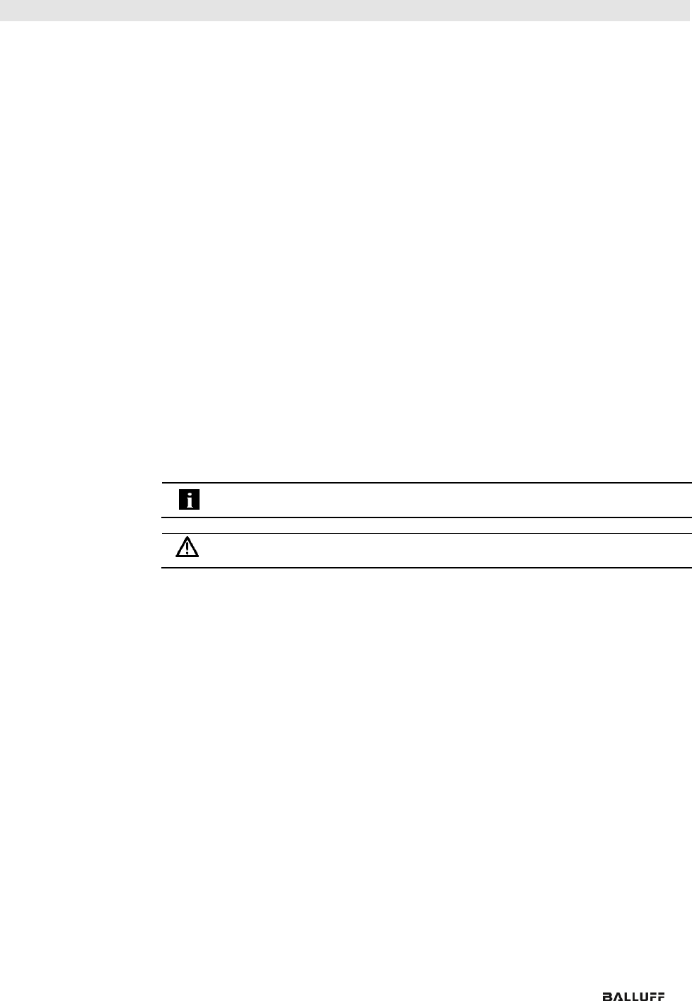
3.1. Module Overview
Figure – Overview: BNI EIP-508-105-R015
1 Mounting hole
2 EtherNet/IP™ port 2
3 Display
4 Power supply, input
5 Status LED: communication / module
6 Port 08 / 09 (IO-Link, standard I/O)
7 Pin/port LED: signal status
8 Port 10 / 11 (IO-Link, standard I/O)
9 Port 12 / 13 (IO-Link, standard I/O)
10 Port 14 / 15 (IO-Link, standard I/O)
11 Port 06 / 07 (IO-Link, standard I/O)
12 Port 04 / 05 (IO-Link, standard I/O)
13 Port 02 / 03 (IO-Link, standard I/O)
14 Port 00 / 01 (IO-Link, standard I/O)
15 Power supply, output
16 EtherNet/IP™ port 1
17 Ground connection
1
6
2
3
12
11
13
14
15
17
8
10
7
9
16
5
4
1
Balluff Network Interface EtherNet/IP™
www.balluff.com
6
3 First Steps
3.2. Mechanical
Connection
The module is secured by means of two M6 screws and two washers.
Insulation support is available separately.
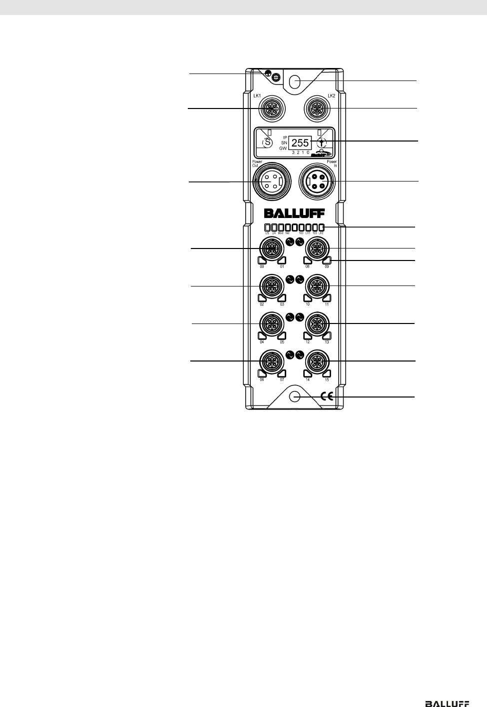
3.3. Electrical
Connection
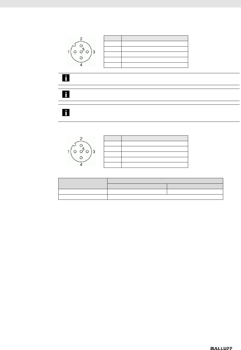
Power Supply
IN
7/8”, male
OUT
7/8” female
Pin
Function
Description
1
+24 V
Actuator supply
2
+24 V
Module / sensor supply
3
0 V
GND module / sensor and actuator supply
4
Note
Where possible, use a separate power source to supply the sensor/bus and
actuator with power.
Total current < 9 A The total current of all modules must not exceed 9 A even in
the case of series connection of the actuator supply.
Grounding
Note
The functional ground connection between housing and machine must have a
low impedance and be as short as possible.
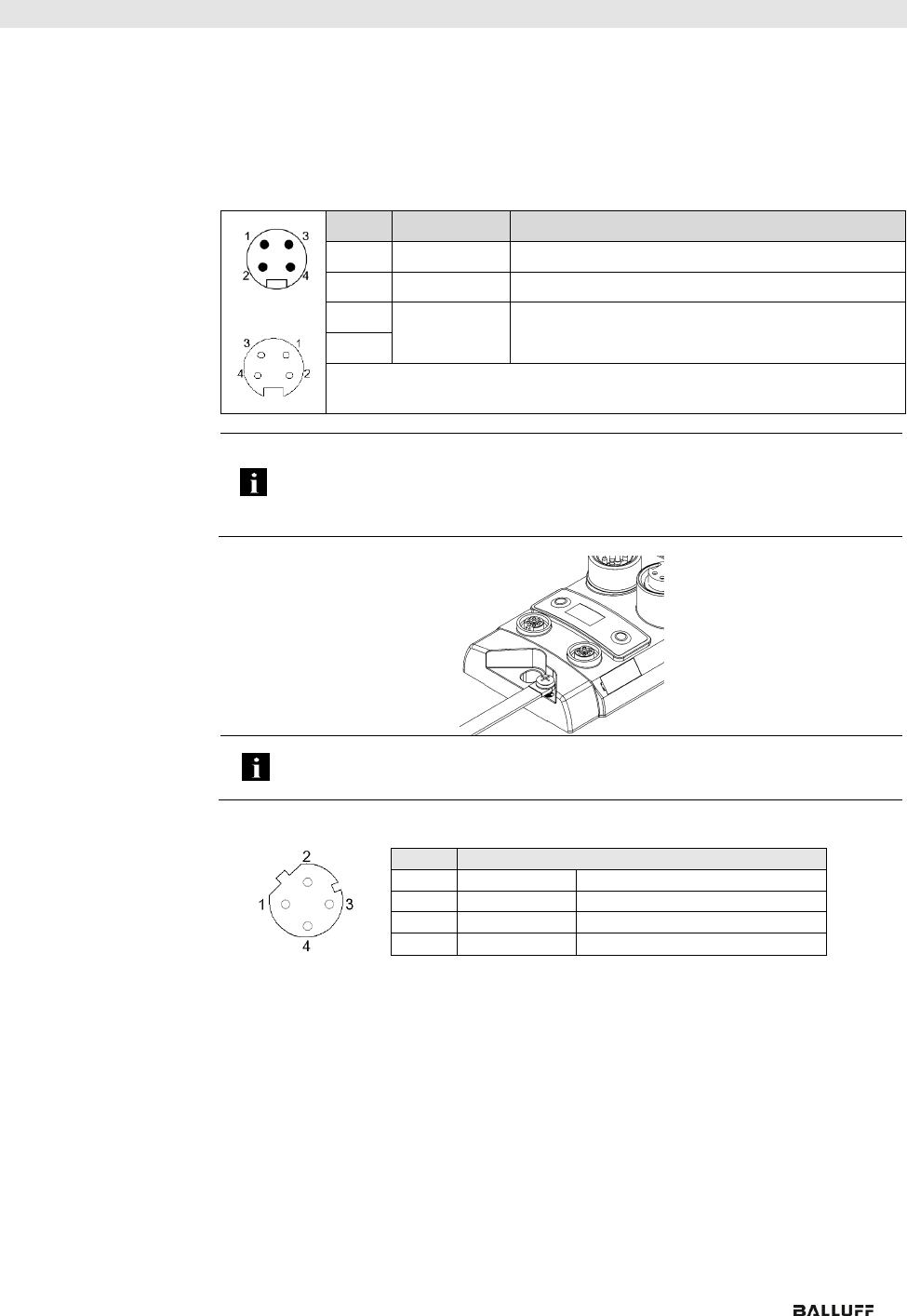
Ethernet IP
Interface
M12, D-coded, female
Pin
Function
1
Tx+
Transmit Data +
2
Rx+
Receive Data +
3
Tx-
Transmit Data -
4
Rx-
Receive Data -
www.balluff.com
7
3 First Steps
I/O Port
M12, A-coded, female
Pin
Function
1
+24 V, 200 mA
2
Input/output 2A
3
GND
4
Input/output 2A
5
FE
Note
For the digital sensor inputs, refer to guideline on inputs EN 61131-2, Type 2.
Note
The total current of the module must not exceed 9 A.
Note
Unused I/O ports must be provided with cover caps to comply with degree of
protection IP67.
IO-Link Port
M12, A-coded, female
Pin
Function
1
+24 V, 1.6 A
2
Input/output 2A
3
GND
4
IO-Link/input/output 2A
5
n.a.
Port
Port
00/01, 02/03, 08/09, 10/11
04/05, 06/07, 12/13, 14/15
BNI EIP-502-105-R015
IN / OUT
IN / OUT / IO-Link
BNI EIP-508-105-R015
IN / OUT / IO-Link
Balluff Network Interface EtherNet/IP™
www.balluff.com
8
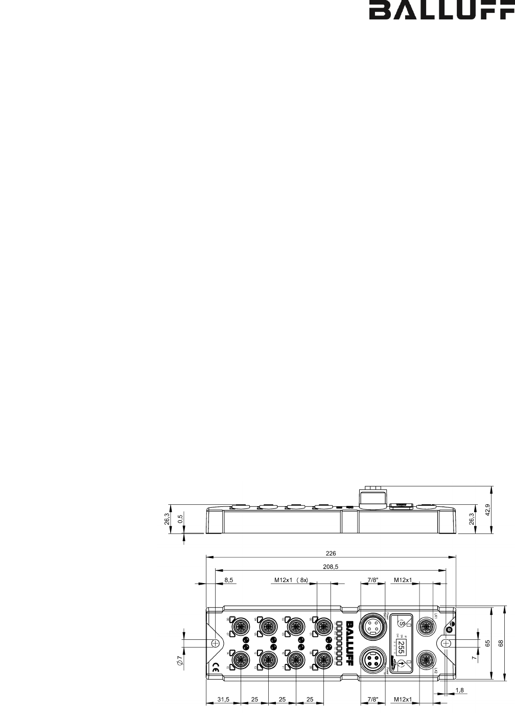
4 Technical Data
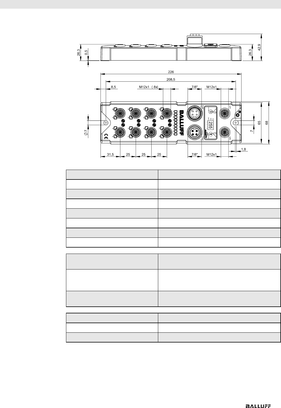
4.1. Dimensions
4.2. Mechanical Data
Housing material
Plastic housing, resistant (Fortron 6165 A6 black)
Enclosure rating per IEC 60529
IP 67 (only when plugged-in and threaded-in)
Supply voltage
7/8" 4-pin, connector / female
Input ports / output ports
M12, A-coded (8x female)
Dimensions (W x H x D in mm)
68 x 226 x 42.9
Type of mounting
Screw mounting with 2 mounting holes
Ground strap installation
M4
Weight
Approx. 670 gr.
4.3. Operating
Conditions
Operating temperature Ta
Storage temperature
-5 °C ... 70 °C
-25 °C ... 70 °C
EMC
- Immunity
- Emission
EMC Directive 2004/108/EEC
- EN 61000-6-2
- EN 61000-6-4
Shock/vibration
EN 60068-2-6, EN 60068-2-27
EN 60068-2-29, EN 60068-2-64
4.4. Electrical Data
Supply voltage
18...30.2 V DC, in accordance with EN 61131-2
Ripple
< 1%
Input current at 24 V
130 mA
www.balluff.com
9
4 Technical Data
4.5. Ethernet
Ethernet IP port
2 x 10Base/100Base Tx
Connection for Ethernet IP port
M12, D-coded, female
Cable types in accordance with
IEEE 802.3
Shielded, twisted pair min. STP CAT 5/ STP CAT 5e
Data transmission rate
10/100 Mbps
Max. cable length
100 m
Flow control
Half-duplex/full-duplex (IEEE 802.33x pause)
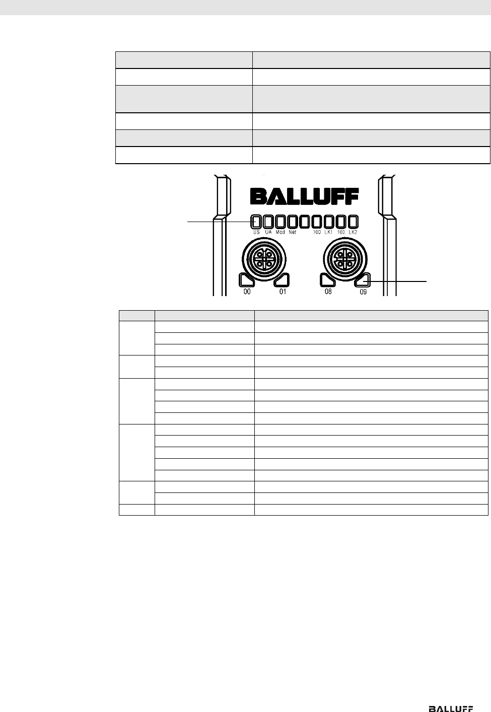
4.6. Function
Indicators
Module Status
LED
Display
Description
UA
Green
Output power OK
Red, flashing
Low output power (< 18V)
Red
No output power (< 11V)
US
Green
Input power OK
Red, flashing
Low input power (< 18V)
Mod
Green, flashing
Incorrect or no configuration of the module
Green
Module is working
Red, flashing
Fixed bus clock is not possible
Red-green, flashing
Initial sequence
Netw
ork
Off
Module has no IP address
Green, flashing
Module has IP, but no connection established
Green
Connection established
Red, flashing
Connection timeout
Red-green, flashing
Initial sequence
100
Off
Bus clock: 10 Mbps
Yellow
Bus clock: 100 Mbps
LNK
Green
Data transfer
Status LEDs
Port LEDs

Balluff Network Interface EtherNet/IP™
www.balluff.com
10
4 Technical Data
Port
Each port has two bicolored LEDs for displaying the I/O statuses.
Display
Status
Description
I/O port
Off
I/O status
The status of the input or output pins is 0
Yellow
I/O status
The status of the input or output pins is 1
Red,
flashing
Short-circuit
Short-circuit between pin 1 and 3
Red
Short-circuit
Short-circuit at dedicated pin
IO-Link port
Green
IO-Link
IO-Link communication active
Green,
flashing
IO-Link
No IO-Link communication
Green,
rapidly
flashing
IO-Link
IO-Link pre-operate during data storage
Red
Short-circuit
Short-circuit at pin 4
Red,
flashing
quickly
IO-Link
Validation failed /
Data storage failed /
Wrong device for data storage
www.balluff.com
11
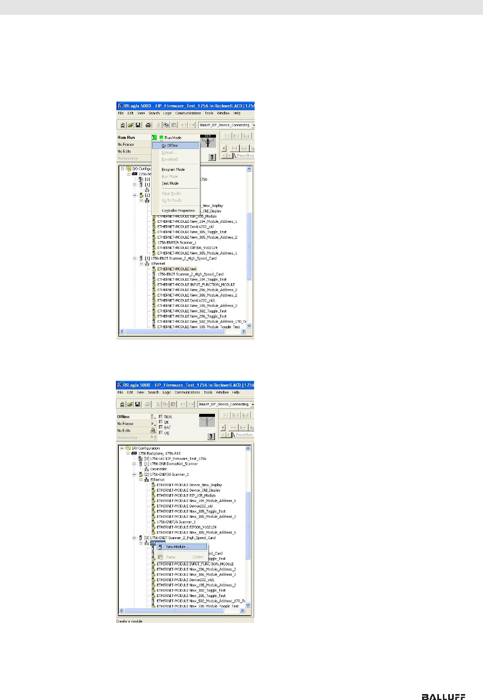
5 Integration
5.1. Integration in
Rockwell RS
Logix 5000
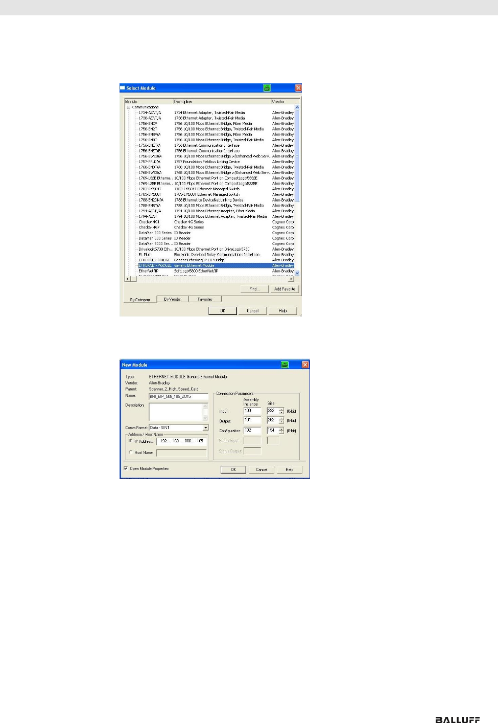
Here you see an example of how the module can be integrated into a Rockwell RS Logix
5000:
First go offline
Right-click Ethernet (on the correct scanner card)
Select a new module
Balluff Network Interface EtherNet/IP™
www.balluff.com
12
5 Integration
Then select the general Ethernet module as the ETHERNET module in the communication
path
Now enter a user-defined tag name to select the general format Data-SINT, to enter the IP
address of the module and to enter the correct connection parameters.
www.balluff.com
13
5 Integration
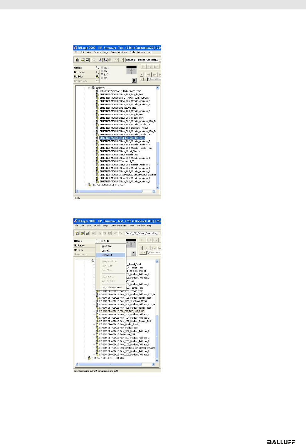
The new module and corresponding controller tags are generated automatically.
Then download the configuration
Balluff Network Interface EtherNet/IP™
www.balluff.com
14
5 Integration
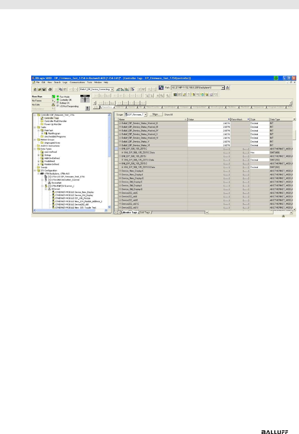
When the download is done, you can observe and control the tags using the Controller Tags option. Make
sure you select the correct tag name, which you configured beforehand.
The input, output and configuration data for this is described on the following pages.
You can use these tags for the programming, too.

www.balluff.com
15
5 Integration
5.2. Address
Specifications
These settings are factory-set.
IP-Adresse: 192.168.1.1
Subnetmaske: 255.255.255.0
Gatewayadresse: 192.168.1.1
5.3. Data
Configuration
Please enter the following values in the control system. They describe the data sizes of the
input, output and configuration data.
Instanc ID
Data length
502
508
507
527
508-C06
Input
100
200
392
196
196
128
Output
101
134
262
130
128
86
CONFIG
102
98
194
98
98
0
5.4. Configuration
Data
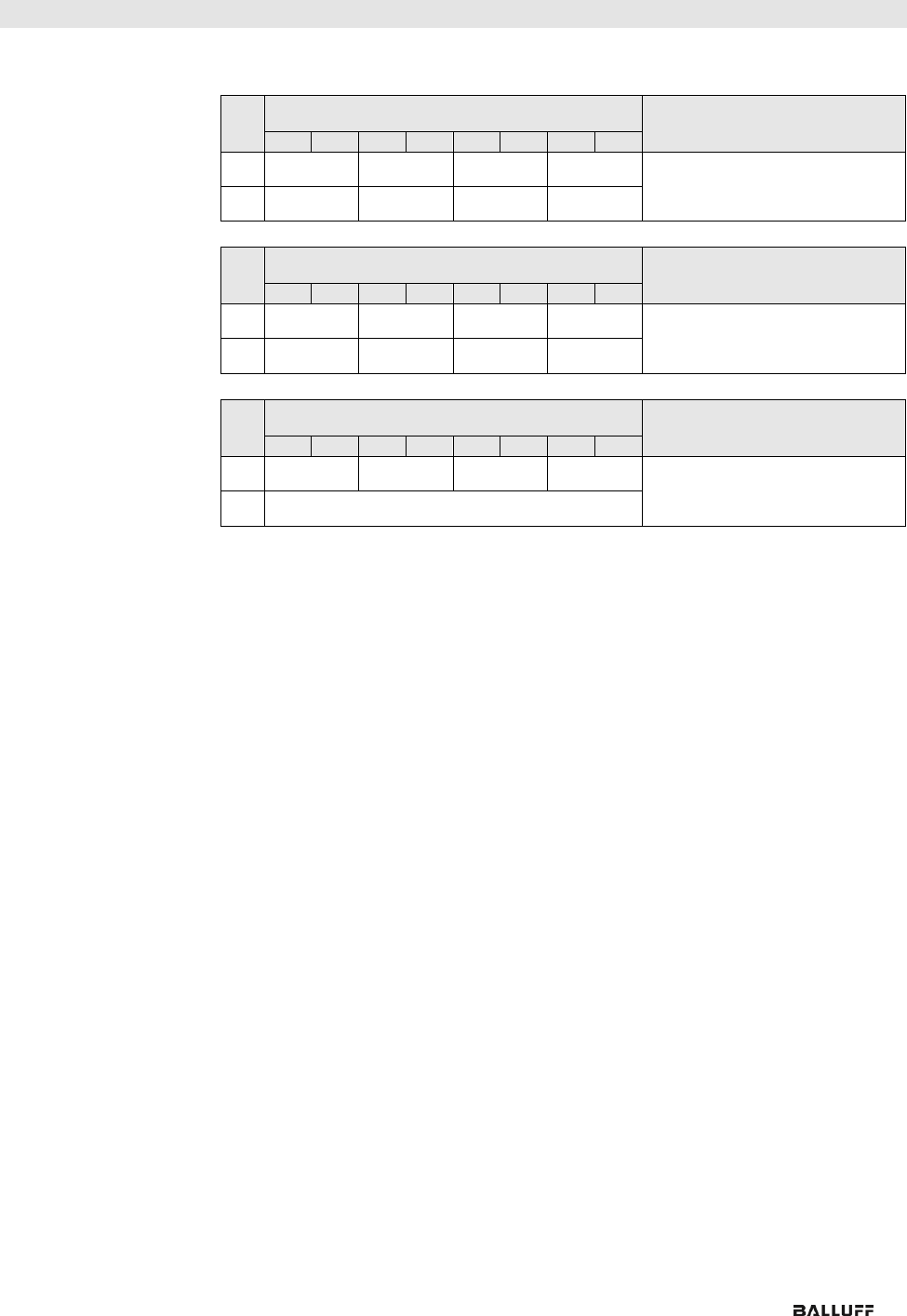
The following tables show an allocation of the configuration data sequence. The standard
values specified below describe a configuration with the IO-Link function at Pin 4 and
standard I/O functions at Pin 2 and 4 of each port. The input and output functions of the
configured standard I/O ports are set via the process data.
BNI EIP-502-105-XXXX, BNI EIP-507-005-Z040, BNI EIP-527-005-Z040
Byte
Slot
Module part
Description
0…1
1
Module
General configuration for the entire module
2…25
2
IO-Link port 0
Configuration of IO-Link port 0
26…49
3
IO-Link port 1
Configuration of IO-Link port 1
50…73
4
IO-Link port 2
Configuration of IO-Link port 2
74…97
5
IO-Link port 3
Configuration of IO-Link port 3
BNI EIP-508-105-XXXX
Byte
Slot
Module part
Description
0…1
1
Module
General configuration for the entire module
2…25
2
IO-Link port 0
Configuration of IO-Link port 0
26…49
3
IO-Link port 1
Configuration of IO-Link port 1
50…73
4
IO-Link port 2
Configuration of IO-Link port 2
74…97
5
IO-Link port 3
Configuration of IO-Link port 3
98…121
6
IO-Link port 4
Configuration of IO-Link port 4
122…145
7
IO-Link port 5
Configuration of IO-Link port 5
146…169
8
IO-Link port 6
Configuration of IO-Link port 6
170…193
9
IO-Link port 7
Configuration of IO-Link port 7
Note
The BNI EIP-508-XXX-XXXX-C06 has no configuration data. These are fixed
and can not be changed.
Balluff Network Interface EtherNet/IP™
www.balluff.com
16
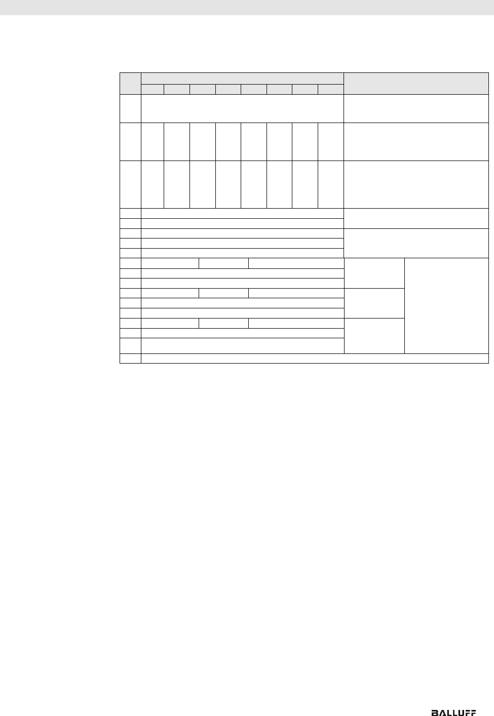
5 Integration
Module
Configuration
BNI EIP-502-105-
XXX
Byte
Bit
Description
7
6
5
4
3
2
1
0
0
P3
P2
-
-
Port function
0x00: Standard I/O
0x01: IO-Link
1
P7
P6
-
-
Module
Configuration
BNI EIP-508-105-
XXX
Byte
Bit
Description
7
6
5
4
3
2
1
0
0
P3
P2
P1
P0
Port function
0x00: Standard I/O
0x01: IO-Link
1
P7
P6
P5
P4
Module
Configuration
BNI EIP-507-005-
Z040, BNI EIP-
527-005-Z040
Byte
Bit
Description
7
6
5
4
3
2
1
0
0
P3
P2
P1
P0
Port function
0x00: Standard I/O
0x01: IO-Link
1
Reserved
Module
Configuration BNI
EIP-508-XXX-
XXXX-C06
The IO-Link ports are always activated.

www.balluff.com
17
5 Integration
IO-Link Port
Configuration
Byte
Bit
Description
7
6
5
4
3
2
1
0
2
Basic
Time
Cycle time
3
Validation type
Validation type
0 No validation
1 compatible (VID + DID)
2 Identical (VID + DID + SerNum)
4
Vendor ID 1
Vendor ID
5
Vendor ID 2
6
Device ID 1
Device ID
7
Device ID 2
8
Device ID 3
9
Serial number 1
Serial number
…
…
24
Serial number 16
25
Parameter server
Parameter server
0x8X Enable
0x0X Disable
0x40 Delete
0xX1 Enable upload
0xX2 Disable download
…
The data of the other IO-Link ports is structured identically and described in the following.
For the BNI EIP-508-xxx-xxxx-C06 these data are not adjustable.

Balluff Network Interface EtherNet/IP™
www.balluff.com
18
Cycle Settings
This parameter can be used to influence the IO-Link communication speed. Calculated
using the multiplier and the time base, the IO-Link cycle time can be increased.
The time base is described in Table B3. The multiplier is entered in decimal form from
0…63.
Bit
Description
7
6
5
4
3
2
1
0
Time
base
Multiplier
Bit 0 to 5: Multiplier
These bits contain a 6-bit multiplier for the
calculation of MasterCycleTime or MinCycle
Time. Permissible values for the multiplier
are
0 to 63.
Bit 6 to 7: Time Base
These bits specify the time base for the
calculation of MasterCycleTime or
MinCycleTime.
Possible values of MasterCycleTime and MiniCycleTime
Time base
encoding
Time base
value
Calculation
Cycle time
00
0.1 ms
Multiplier x time base
0.4 ms to 6.3 ms
01
0.4 ms
6.4 ms + multiplier x time base
6.4 ms to 31.6 ms
10
1.6 ms
32.0 ms + multiplier x time base
32.0 ms to 132.8 ms
11
Reserved
Reserved
Reserved
NOTE: The value 0.4 results from the minimum possible transmission time according to
A.3.7.
Validation
Settings
No validation: validation deactivated, every device will be accepted.
Compatibility: manufacturer ID and device ID are compared to the IO-Link device data.
Identity: manufacturer ID and device ID and serial number are compared to the
IO-Link device data. The IO-Link communication is only started if there is a match.

www.balluff.com
19
5 Integration
Parameter Server
Enable: data management functions enabled, parameter data and identification data of the
IO-Link device are stored permanently.
Disable: data management functions disabled, stored parameter data and identification
data of the IO-Link device remain stored.
Deleted: data management functions disabled, stored parameter data and identification
data of the IO-Link device are deleted.
Enable upload:
If only the upload is enabled, the master always starts an upload of the parameter data. In
this case, the upload is independent of the upload flag of the IO-Link device. If no data is
stored in the Master Port, an upload likewise takes place. (e.g. after deleting the data or
before the first data upload)
Enable download:
If only the download is enabled, the master always starts a download of the parameter data.
In this case, the download is likewise independent of the upload flag of the IO-Link device.
If no data is stored in the Master Port, however, an upload takes place first. (e.g. after
deleting the data or before the first data upload)
Enable upload and download:
If the upload and download are enabled, different parameter sets are distinguished
depending on the upload flag of the IO-Link device.
If no parameter data is stored in the IO-Link master port, an initial upload takes place. (e.g.
after deleting the data or before the first data upload)
If the upload flag is set on the IO-Link device, an upload of the parameter data always takes
place.
If no upload flag is set and parameter data has already been stored, a download of the
parameter data always takes place.
Note
After the upload of the parameter data, the vendor ID and device ID of the
connected IO-Link device are also still saved until the data records are deleted.
When the connected IO-Link device is started, a validation takes place. Thus, only
an IO-Link device of the same type can be used for the data management.
If an IO-Link device of a different type is to be used, the contents of the parameter
server must be deleted.
The data storage is supported only by IO-Link devices with IO-Link Revision 1.1.
Upload Flag on
the IO-Link
Device
The upload flag is needed to overwrite already saved data in the parameter server with new
parameter data of the same IO-Link device.
To enable the upload flag of an IO-Link device,
the data value 0x05 must be entered in the index 0x02, subindex 0.
(For information about configuration via IO-Link, refer to the "Web Server" chapter under
"Device Properties" or the "Configuration via Explicit Messages" chapter
under "IO-Link Device Parameterization")

Balluff Network Interface EtherNet/IP™
www.balluff.com
20
6 Configuration via Explicit Messages
QuickConnect
The QuickConnect function makes it faster to boot up and integrate the BNI EIP-50x-105-
X015 modules.
Enabling QuickConnect automatically takes over all necessary port properties on the module:
Static IP address
Ports at 100 Mbps full-duplex
Auto-negotiation disabled
Auto MDI-X disabled
Prepared for linear topology
You can configure QuickConnect via the following
class instance attribute of the explicit messages:
Class
Instance
Attribute
Value
245 (0xF5)
1 (0x01)
12 (0x0C)
0: disabled (default)
1: enabled
Note
For QuickConnect to be enabled, ACD (Address Conflict Detection) must also be
enabled. This is switched on by default.
The ACD can be reviewed and changed using the following class instance attributes of the
explicit messages:
Class
Instance
Attribute
Value
245 (0xF5)
1 (0x01)
10 (0x0A)
0: disabled
1: enabled(default)

www.balluff.com
21
6 Configuration via Explicit Messages
Rockwell
Automation
Products that
are Compatible
with
QuickConnect
Source:
Allen-Bradley Ethernet/IP QuickConnect Application Technique
Page 13
Balluff Network Interface EtherNet/IP™
www.balluff.com
22
6 Configuration via Explicit Messages
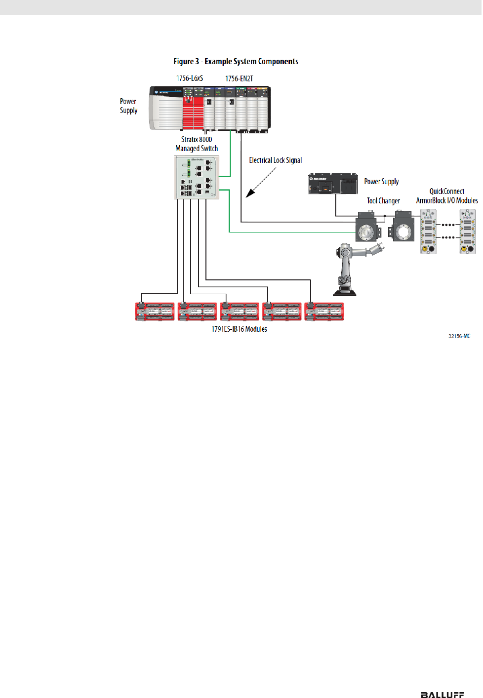
Example with
Rockwell
Components
Source:
Allen-Bradley Ethernet/IP QuickConnect Application Technique, Page 12
Please also note the following:
Direct connection between PLC and QuickConnect slave with crossover cable
Slave-to-slave connection using patch cable
For setting up the topology, only the linear topology with a maximum of 20 modules
on the tool side is permitted.
If needed, only one managed switch may be used between the PLC and Ethernet/IP
slave.
To trigger the QuickConnect sequence, an electrical lock signal is required that
reads in the supply voltage of the QuickConnect slaves via the controller.
www.balluff.com
23
6 Configuration via Explicit Messages
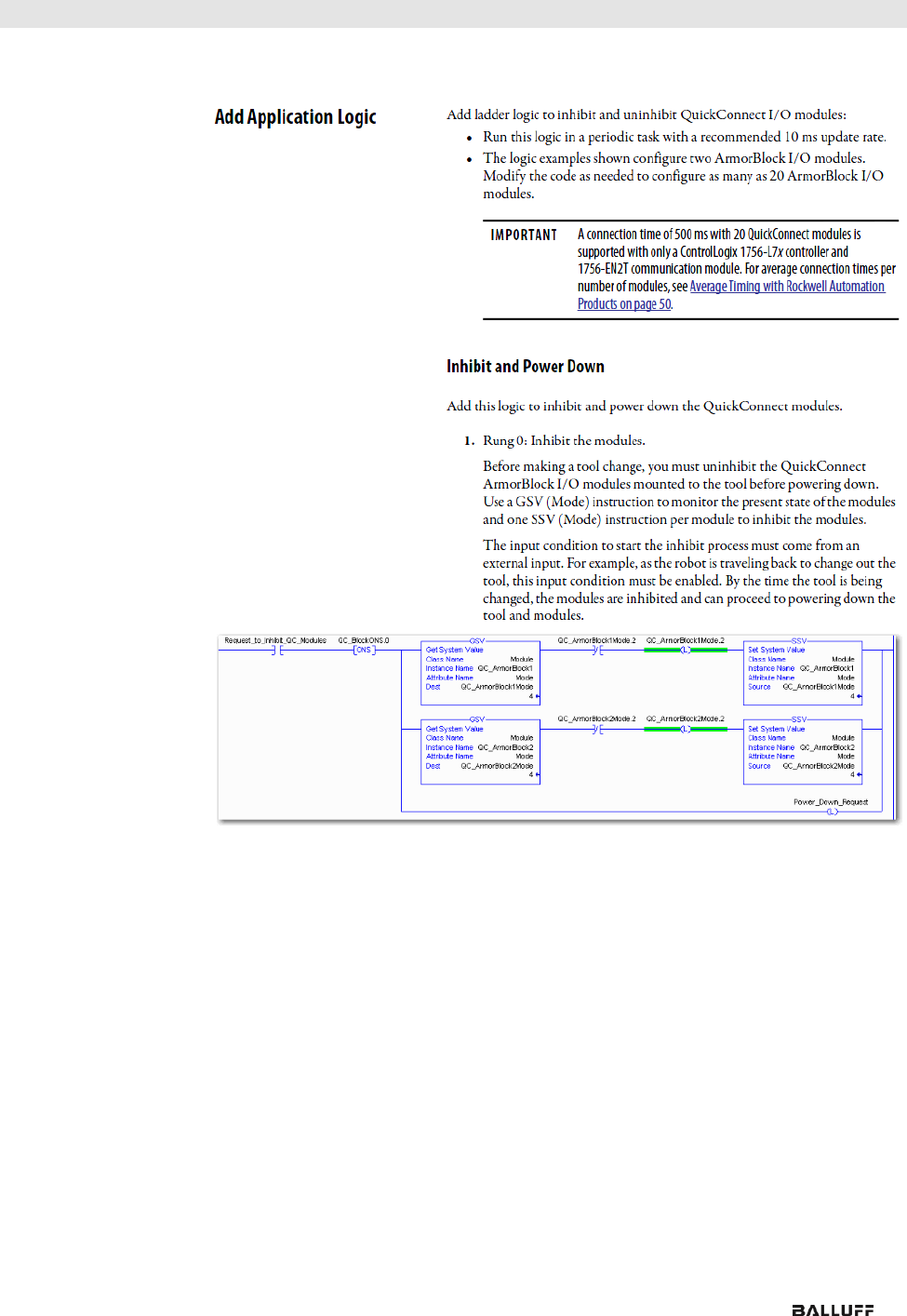
PLC Program
Source:
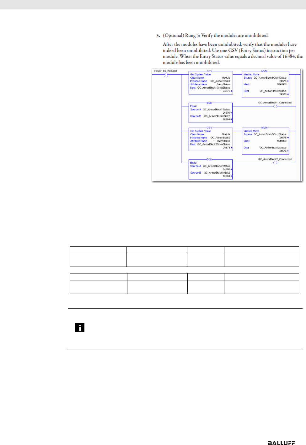
Allen-Bradley Ethernet/IP QuickConnect Application Technique, Page 29
Balluff Network Interface EtherNet/IP™
www.balluff.com
24
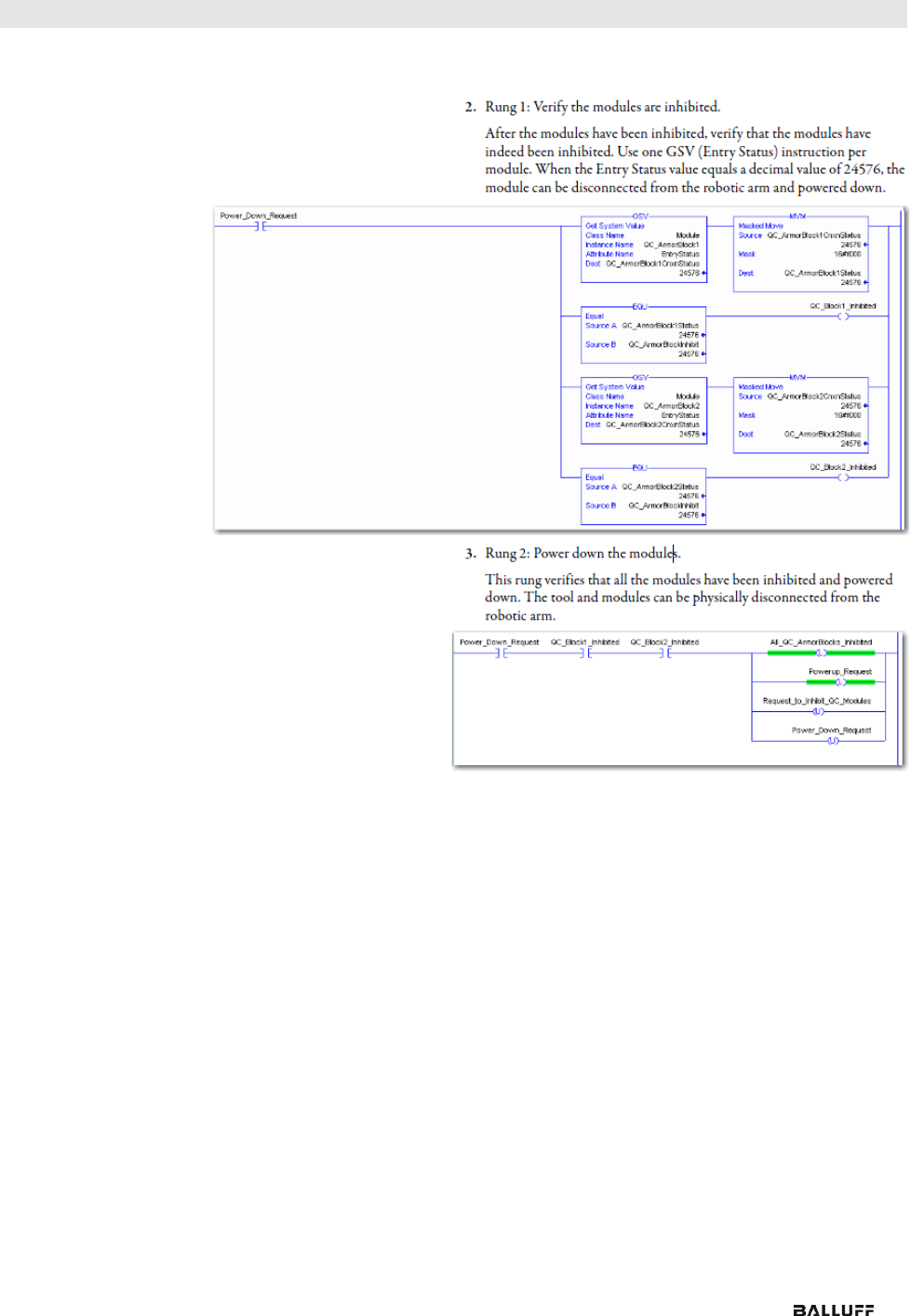
6 Configuration via Explicit Messages
Source:
Allen-Bradley Ethernet/IP QuickConnect Application Technique, Page 30
www.balluff.com
25
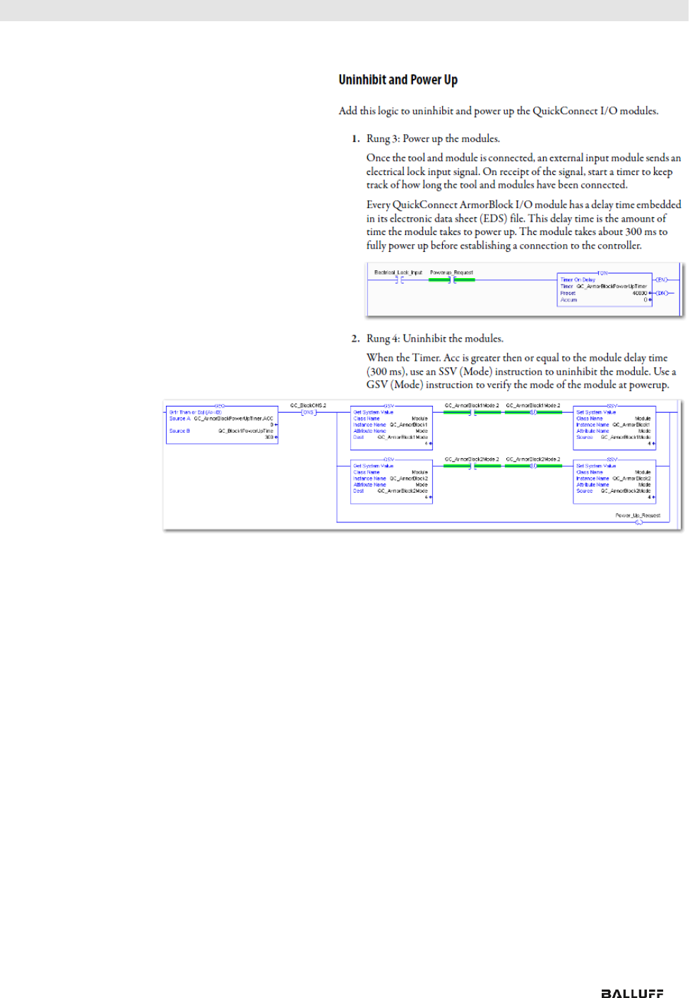
6 Configuration via Explicit Messages
Source:
Allen-Bradley Ethernet/IP QuickConnect Application Technique, Page 31
Balluff Network Interface EtherNet/IP™
www.balluff.com
26
6 Configuration via Explicit Messages
Source:
Allen-Bradley Ethernet/IP QuickConnect Application Technique, Page 32
Fault State
A safe state that the port is to take on in the case of a loss of bus communication can be
predefined for each output on the port pins.
The fault state settings can be configured using the following class instance attributes of the
explicit messages.
Enable/Disable
Fault State
Class
Instance
Attribute
Value
9 (0x09)
1 – m
6
0: Fault state disabled
1: Fault state enabled
Fault State
Action
Class
Instance
Attribute
Value
9 (0x09)
1 – m
5
0: Output on
1: Hold last state
m: Number of outputs
Note
The fault state settings are stored only temporarily in the module. They are deleted
after a power reset.
To ensure a long-term fault state configuration, the configuration has to be
programmed via the PLC so that the settings are transferred to the module again
when the system is restarted.
www.balluff.com
27
6 Configuration via Explicit Messages
IO-Link Device
Para-
meterization
There are two options for configuring an IO-Link device connected to the IO-Link port.
Configuration via the web server
refer to the "Web Server" chapter under "Device Properties"
Configuration via explicit messages
The following example describes how Rockwell RSLogix 5000 devices can be used to
configure an IO-Link device via explicit messages.
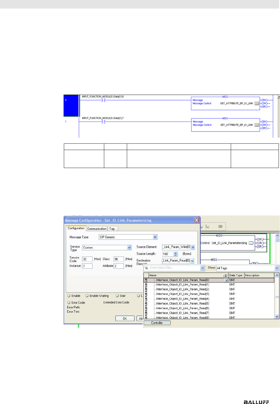
For this purpose, the "MSG" components in the PLC program are used.
Read IO-Link
Parameter
Service Code
Class
Instance
Attribute
0x32
0x96
1 - n
0x03
(Read Parameter)
n: Number of ports
Source Length must correspond to at least the read parameters, but a larger value can also
be entered. (In this example, 100 bytes)
As the Source Element (Write) and as the Destination Element (Read),
create one SINT[100] array each and select the first line[0].
Balluff Network Interface EtherNet/IP™
www.balluff.com
28
6 Configuration via Explicit Messages
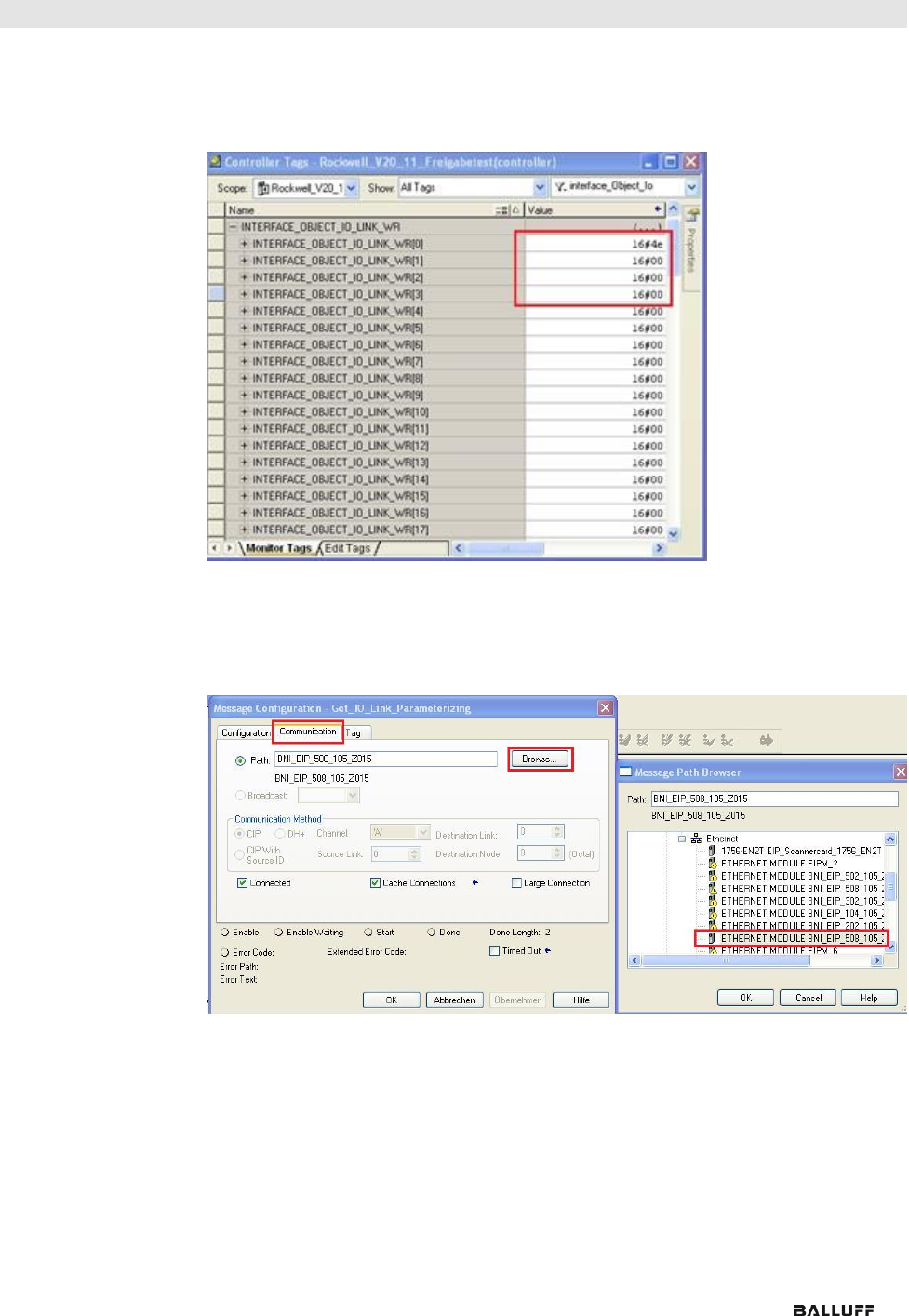
In the Source Element Array (Write), enter which index is to be read.
In this example, this is index 0x4E.
Destination Array (Read) shows the read-out value.
In case of a configuration error, the error code is likewise displayed there.
In the "Communication" window, you have to select the Ethernet module
on which the configuration is to take place.
www.balluff.com
29
6 Configuration via Explicit Messages
Write IO-Link
Parameter
Service Code
Class
Instance
Attribute
0x32
0x96
1 - n
0x02
(Write
Parameter)
n: Number of the ports
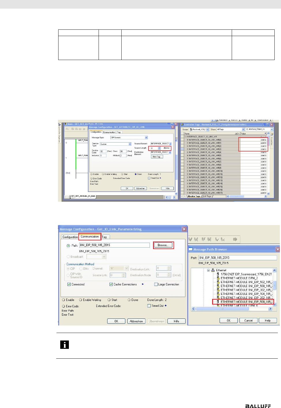
Source Element and Destination Element are to be selected so they are identical to the
previous example, "Read IO-Link parameter".
The Source Length must be exactly the same length as the parameter data to be written.
In this example, index 0x4E, subindex 0,
value 0x02 is written in Source Element Array (Write).
In case of a configuration error, an error code appears in Destination Element Array (Read).
In the "Communication" window, you likewise have to select the Ethernet module
on which the configuration is to take place.
Note
The explicit messages functions are implemented in accordance with the
Volume 1: Common Industrial Protocol Specification and
Volume 2: Ethernet/IP Adaption of CIP.

Balluff Network Interface EtherNet/IP™
www.balluff.com
30
7 Process Data
7.1. Process Data
Inputs
The input data size is 200 bytes. Take a look at the tables below for the allocation of the
process data inputs.
BNI EIP-502-105-R015
Byte
Module part
Description
0…7
Standard I/O ports
Process data inputs at the standard inputs
8…55
IO-Link port 1
Process data inputs at IO-Link port 1
56…103
IO-Link port 2
Process data inputs at IO-Link port 2
104…151
IO-Link port 3
Process data inputs at IO-Link port 3
152…199
IO-Link port 4
Process data inputs at IO-Link port 4
BNI EIP-508-105-R015
Byte
Module part
Description
0…7
Standard I/O ports
Process data inputs at the standard inputs
8…55
IO-Link Port 0
Process data inputs at IO-Link port 0
56…103
IO-Link port 1
Process data inputs at IO-Link port 1
104…151
IO-Link port 2
Process data inputs at IO-Link port 2
152…199
IO-Link port 3
Process data inputs at IO-Link port 3
200…247
IO-Link port 4
Process data inputs at IO-Link port 4
248…295
IO-Link port 5
Process data inputs at IO-Link port 5
296…343
IO-Link port 6
Process data inputs at IO-Link port 6
344…391
IO-Link port 7
Process data inputs at IO-Link port 7
Standard Input
Data
BNI EIP-502-105-R015 and BNI EIP-508-105-R015
Byte
Bit
Description
7
6
5
4
3
2
1
0
0
I32
I34
I22
I24
I12
I14
I02
I04
Input data
I04
Input at port 0, pin 4
The result is 0 only if the port is
configured as an IO-Link port.
1
I72
I74
I62
I64
I52
I54
I42
I44
2
S3
S2
S1
S0
Short-circuit status
Short-circuit between pin 1 and 3
at the registered port
3
S7
S6
S5
S4
4
O32
O34
O22
O24
O12
O14
O02
O04
Overload status
O04
Overload at port 0, pin 4
Only if the port is configured as an
output.
5
O72
O74
O62
O64
O52
O54
O42
O44
6
0
0
0
0
0
NA
PS
PA
Status of the power supply
NV: No actuator power supply
PS: Power supply for sensor
PA: Power supply for actuator
7
0
0
0
0
0
0
0
0
Reserved
www.balluff.com
31
7 Process Data
IO-Link Input Data
BNI EIP-502-105-R015 and BNI EIP-508-105-R015
Byte
Bit
Description
7
6
5
4
3
2
1
0
8
…
39
IO-Link port 0 input data
40
0
0
0
0
0
0
DC
IOL
IO-Link status
IOL: Port in IO-Link mode
DC: Device connected
0: Reserved
41
SC
0
0
0
0
PDI
DF
VF
IO-Link error
VF: Validation failed
SC: IO-Link short-circuit
DF: Data storage validation failed
PDI: Process data invalid
42
Vendor ID 1
Vendor ID
43
Vendor ID 2
44
Device ID 1
Device ID
45
Device ID 2
46
Device ID 3
47
Mode
Type
0
Event 1
Mode:
0: Reserved
1: Event single shot
2: Event disappears
3: Event appears
Type:
0: Reserved
1: Notification
2: Warning
3: Error
48
Event code high
49
Event code low
50
Mode
Type
0
Event 2
51
Event code high
52
Event code low
53
Mode
Type
0
Event 3
54
Event code high
55
Event code low
…
The data of the other IO-Link ports are structured identically and described in the following.
Balluff Network Interface EtherNet/IP™
www.balluff.com
32
7 Process Data
7.2. Process Data
Outputs
The output data size is 134 bytes. Take a look at the tables below for the allocation of the
process data outputs.
BNI EIP-502-105-R015
Byte
Module part
Description
0…5
Standard I/O ports
Process data outputs at the standard inputs
6…37
IO-Link port 1
Process data outputs at IO-Link port 1
38…69
IO-Link port 2
Process data outputs at IO-Link port 2
70…101
IO-Link port 3
Process data outputs at IO-Link port 3
102…133
IO-Link port 4
Process data outputs at IO-Link port 4
BNI EIP-508-105-R015
Byte
Module part
Description
0…5
Standard I/O ports
Process data outputs at the standard inputs
6…37
IO-Link Port 0
Process data output at IO-Link port 0
38…69
IO-Link port 1
Process data output at IO-Link port 1
70…101
IO-Link port 2
Process data output at IO-Link port 2
102…133
IO-Link port 3
Process data output at IO-Link port 3
134…165
IO-Link port 4
Process data output at IO-Link port 4
166…197
IO-Link port 5
Process data output at IO-Link port 5
198…229
IO-Link port 6
Process data output at IO-Link port 6
230…261
IO-Link port 7
Process data output at IO-Link port 7
Standard Output
Data
Byte
Bit
Description
7
6
5
4
3
2
1
0
0
O32
O34
O22
O24
O12
O14
O02
O04
Output data
O04
Output at port 0, pin 4
To use this function at an IO-
Link port, the port has to be
configured as an output.
1
O72
O74
O62
O64
O52
O54
O42
O44
2
R32
R34
R22
R24
R12
R14
R02
R04
Restart
Restart of the output after a
short-circuit is detected
3
R72
R74
R62
R64
R52
R54
R42
R44
4
0
0
0
0
0
0
0
0
Reserved
5
0
0
0
0
0
DL
GO
RO
Display control system
DL: Display disabled / PLC
lock
GO: Green display LED
illuminates
RO: Red display LED
illuminates
IO-Link Output
Data
Byte
Bit
Description
7
6
5
4
3
2
1
0
6…37
IO-Link port 0 output data
…
The data of the other IO-Link ports are structured identically and described in the
following.
www.balluff.com
33
8 Display
8.1. General
With the implemented display, the address is output directly to the devices BNI EIP…
The following address types are possible:
• IP address
• Subnet mask
• Gateway address
Each address is composed of 4 octets.
The display also shows information about the hardware and firmware update.
The display has a locking function that can be enabled from the control panel. If the lock is
set, no more editing can be done (see bit layout, Chapter 6.2 Standard output data).
8.2. Address
Specifications
IP address: 192.168.1.1
Subnet mask: 255.255.255.0
Gateway address: 192.168.1.1
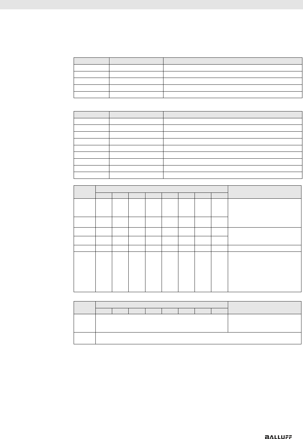
8.3. Control and
Display
1 Display
2 Arrow key
3 Octet cursor
4 Address type cursor
5 "Set" key
6 LED
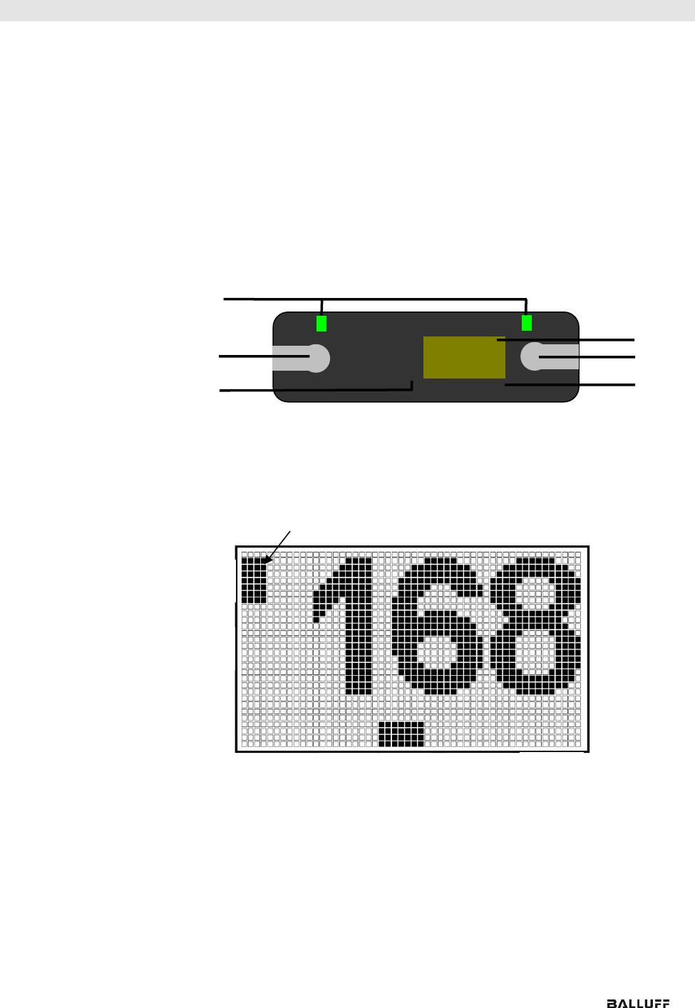
8.4. Display
Information
IP: IP address
SN: Subnet address
GW: Gateway address
3: First octet
2: Second octet
1: Third octet
0: Fourth octet
S
↑
IP
SN
GW
3 2 1 0
1
2
3
4
5
6
2
3
1
0
Cursor for selecting the address type
Cursor for selecting the address type
Cursor for selecting the octet
IP
SN
IP
GW
Balluff Network Interface EtherNet/IP™
www.balluff.com
34
8 Display
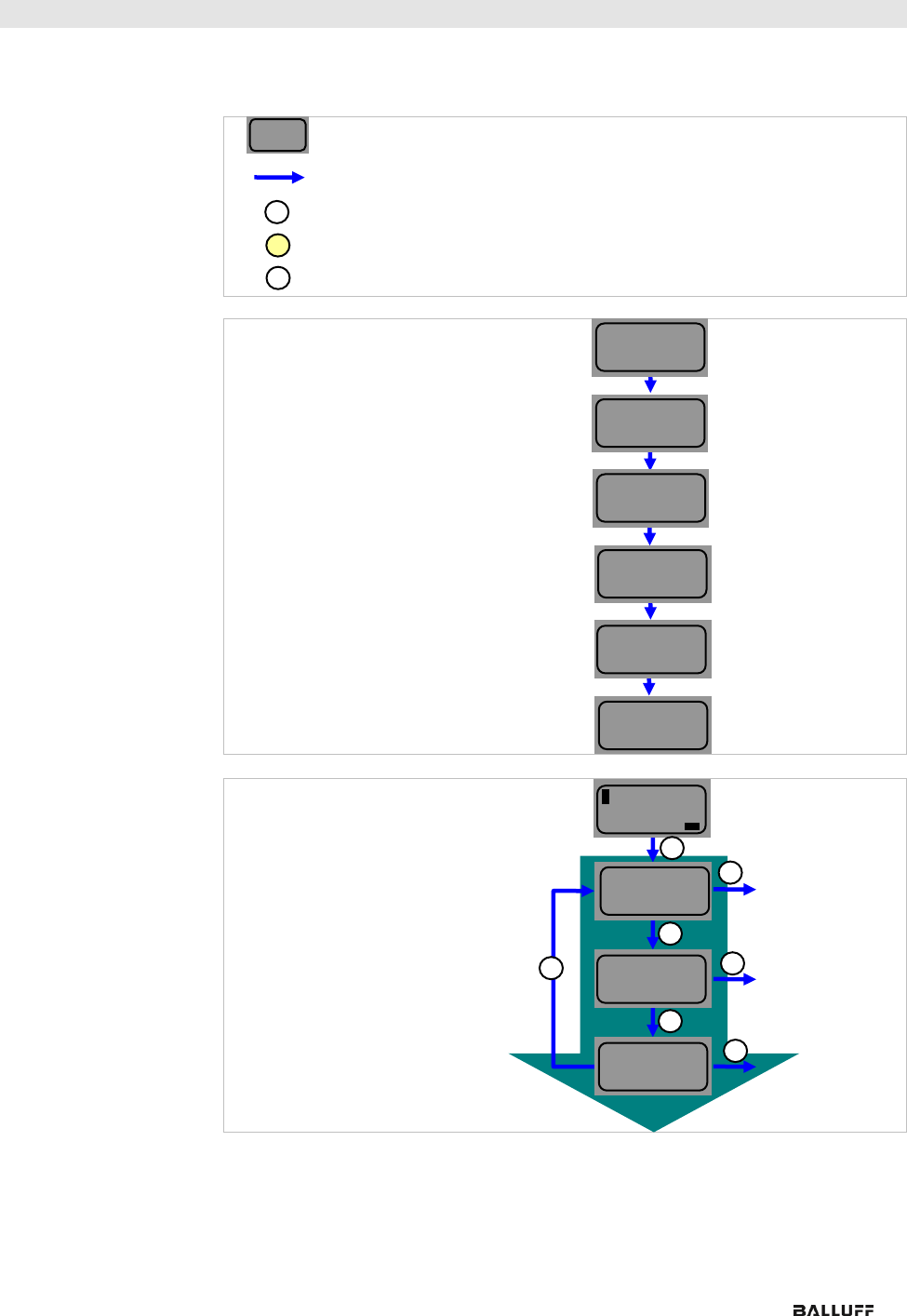
8.5. Design and
Symbols
In the following flow charts, some symbols are used to describe the display functionality:
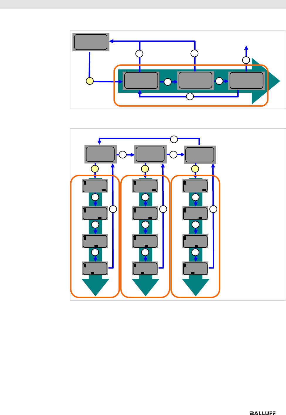
8.6. Startup
8.7. Main Menu
• Press the Set key briefly to scroll through the main menu.
• Press the arrow key to open the menu.
Current status
Switch
S
Condition: Briefly press the Set key
S
Condition: Press and hold the Set key (at least 3 seconds)
Condition: Briefly press the arrow key
IP
192 . 168 .
015 . 005
VERSION
H W : 1 . 0
S W : 1 . 0
Subnet
255 . 255 .
255 . 000
Gateway
000 . 000 .
000 . 000
Hardware and firmware update
Current IP
Current subnet mask
e
Current gateway address
BNI
EIP-508-
105-R015
Module name
B A L L U F F
BALLUFF
Network
Config
Standard view
4th octet of the IP address
Menu: Network Config
Menu: IP Setup
Menu: Module Information
007
…
…
S
S
S
S
…
IP
SETUP
MODULE
INFO
www.balluff.com
35
8 Display
8.8. IP Setup
• Press and hold the Set key to call up the editing mode.
• The preferred value is configured by briefly pressing the arrow key.
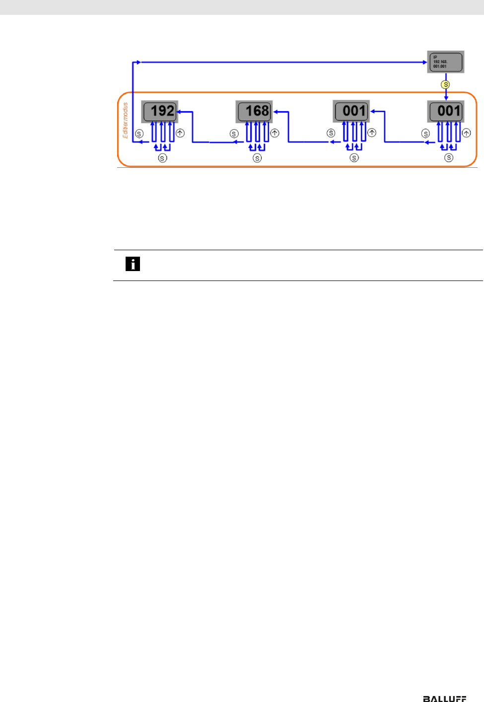
8.9. Network Config
• Press and hold the Set key to call up the editing mode.
• The preferred value is configured by briefly pressing the arrow key.
• Press and hold the arrow key to call up the fast program mode.
• Briefly pressing the Set key saves the entered value and scrolls to the next octet.
The 4th octet represents the beginning of the editing process.
• The completely entered address is saved by briefly pressing the Set key when
editing the first octet. The entered value appears right afterwards in the IP overview
display.
• Manual changes to IP, subnet or gateway lead to an automatic change of the IP
setup to "static".
STATIC
DHCP
X FACTORY SETTING
STATIC
X DHCP
FACTORY SETTING
X STATIC
DHCP
FACTORY SETTING
S
S
S
S
Editing mode
X STATIC
DHCP
FACTORY SETTING
IP editing mode
IP
192.168.
015.005
Subnet
255.255.
255.000
Gateway
000.000.
000.000
Editing mode
Programming mode
005
015
168
192
S
S
S
S
S
Editing mode
Programming mode
000
255
255
255
S
S
S
S
S
Editing mode
Programming mode
000
000
000
000
S
S
S
S
S
Balluff Network Interface EtherNet/IP™
www.balluff.com
36
8 Display
8.10. Edit mode
• In the Network Configuration menu, select IP / Subnet or Gateway Address.
• Press the set button long to switch to edit mode.
• Press the arrow key briefly to change the number.
• Press the Set button briefly to move to the next position.
• After the last digit, press the set button briefly to move to the next octet of the address
or to accept the new number after the last octet.
Note
The module has to be restarted to work with the new configuration.
www.balluff.com
37
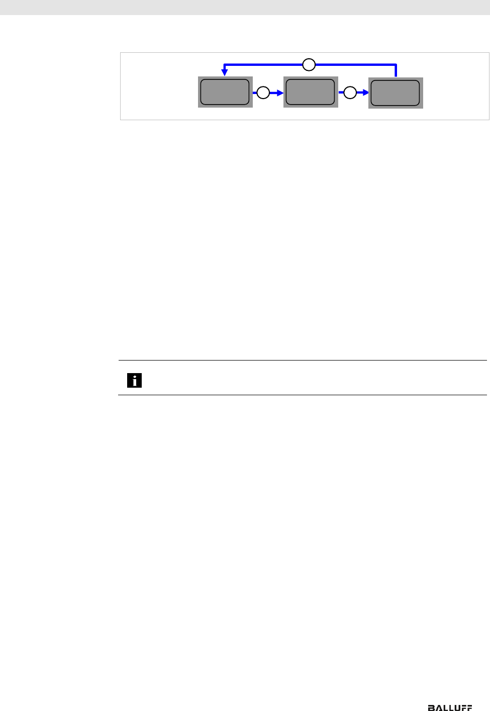
8 Display
8.11. Module
Information
• Briefly pressing the arrow key allows scrolling through the "Module information"
menu.
• The product name, module updates and Mac-ID are displayed as information.
8.12. General
Information
• Press and hold the arrow key to scroll quickly in editing mode.
• If no key is pressed for 10 seconds, the view reverts to the standard display (4th
octet of the IP address). Changes that have not been saved will be lost.
• Differences between the new configuration and the configuration with which the
module works are indicated by an unequal sign. In this case, the screen switches
to the standard display after 5 seconds.
• The display flashes in editing mode. The display flickers in fast scroll mode.
• If the module receives a single ping, the word "Ping" appears on the display for a
couple of seconds. Then the previous display returns. You can exit ping mode
sooner by briefly pressing the Set key.
• If the module receives two or more pings, the word "Ping" appears on the display.
You can exit the display only by briefly pressing the Set key. Then the display
before the ping returns.
• The LED function of the display LEDs can be set in a user-specific manner by
setting several bits in the process data outputs. (see bit layout, standard output
data)
• The plc lock function can also be used by setting a bit in the process data outputs.
(see bit layout, standard output data)
Note
You cannot select editing mode in the display if the plc lock is set in the process
data inputs by a bit (see bit layout, standard output data)
BNI
EIP-508-
105-R015
Version
SW: x.x
HW: x.x
MAC ID
XX : XX : XX :
XX : XX : XX
Balluff Network Interface EtherNet/IP™
www.balluff.com
38
9 Web Server
9.1. General
The BNI fieldbus module contains an integrated web server for retrieving detailed device
information and for configuring the device.
To use the web interface you must first ensure that the module has been correctly integrated
into your network. In addition the IP subnet of the BNI module must be accessible from the
PC on which the browser is running. Please use Internet Explorer 10 or newer as the browser;
older versions may result in display problems.
For open a connection with the web server, enter the IP address of the module in the address
line of the browser. The homepage then appears with the essential device information.
www.balluff.com
39
9 Web Server
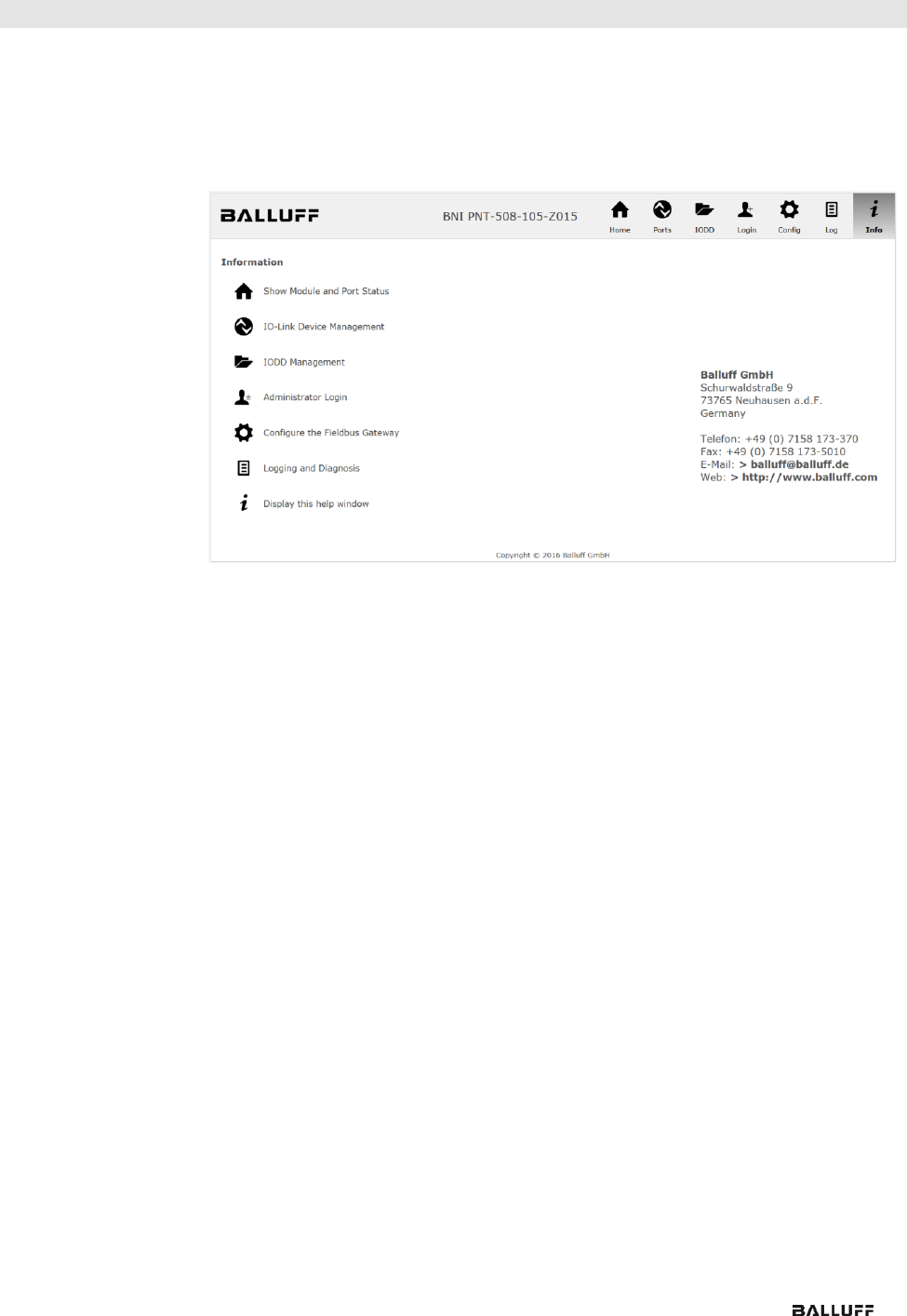
9.2. Navigation / Info
The navigation bar is located in the upper area of the window, which allows you to switch
between the various dialogs of the web interface. To do this click on the corresponding icon.
When the "Info" tab is selected the following overview appears:
The "BALLUFF" logo at upper right links to the international Balluff homepage.
Balluff Network Interface EtherNet/IP™
www.balluff.com
40
9 Web Server
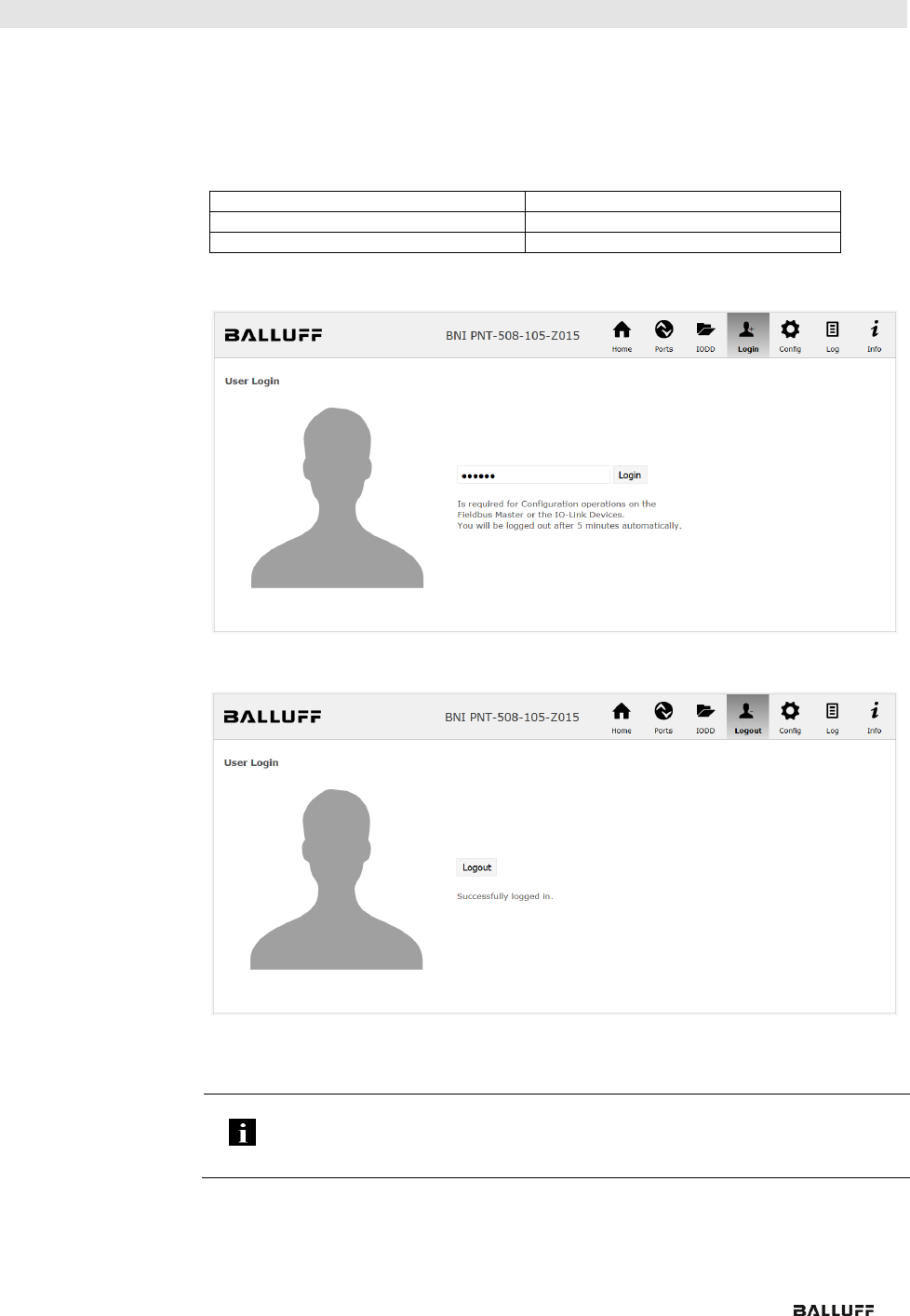
9.3. Login/Logout
To make configuration settings on the fieldbus module using the web interface, you must first
log in. Functionalities which cannot be used without logging in are indicated by the grayed out
buttons.
The default password is:
BNI PNT-XXX-XXX-XXXX
"BNIPNT“
BNI EIP-XXX-XXX-XXXX
"BNIEIP“
BNI ECT-XXX-XXX-XXXX
"BNIECT“
The password cannot be changed!
After successfully logging in the dialogs are shown as follows:
Use the "Logout" button to log out again. After 5 minutes of no interaction with the Webserver
the user is automatically logged out.
Note
For security reasons the fieldbus module shows only one login at a time with
configuration access. Reading (without logging in) is however possible from multiple
PCs at the same time on the fieldbus module.
www.balluff.com
41
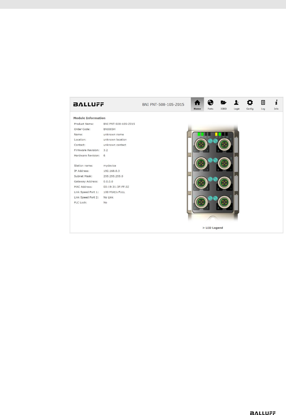
9 Web Server
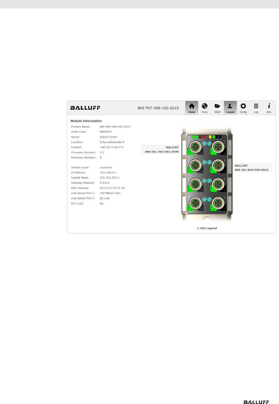
9.4. "Home" dialog
Under "Home" you are given the essential information about the fieldbus itself and its network
activity. You are also shown whether the configuration block was enabled by the controller
(PLC).
Information is also shown about the current process data and the status of the module via
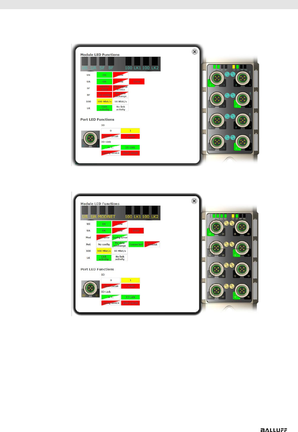
the corresponding LEDs. After selecting "LED Legend" a Help dialog appears which explains
the meaning of the LEDs.
If an IO-Link device is connected to one of the configured IO-Link terminals, some of the
device data will be displayed in addition to the module data in the form of a link. After selecting
one of these links the corresponding device dialog is opened.
Balluff Network Interface EtherNet/IP™
www.balluff.com
42
9 Web Server
PNT:
EIP:
www.balluff.com
43
9 Web Server
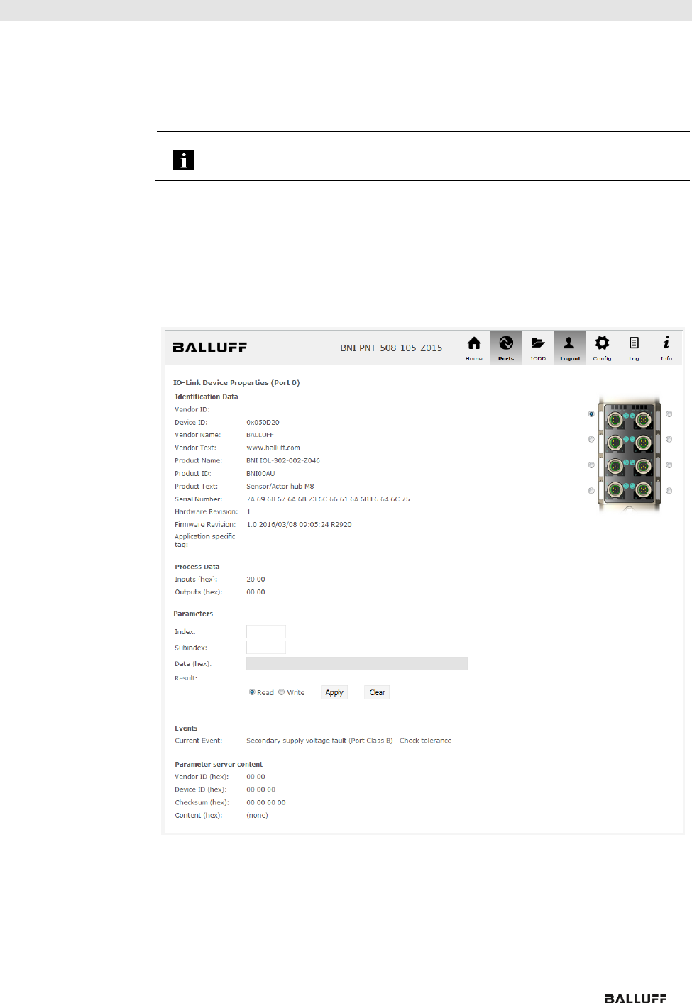
9.5. "Ports" dialog
The "Ports" dialog displays information and process data for the connected IO-Link devices.
Select the desired IO-Link Port in the image of the fieldbus module on the right side to see the
device data.
Note
The IO-Link device data are only displayed if the port is also
configured as an IO-Link port!
No appropriate
IODD uploaded
It is possible to read and write the configuration parameters of the IO-Link device via the
"Parameters" option. The parameter indexes and subindexes of the IO-Link device are
described in the corresponding separate user's guide (and follow the IO-Link conventions).
Under "Events" you can see whether a diagnostic event from the IO-Link device exists.
Under "Parameter Server Content" you can view the content of the parameter server if
parameter data is stored on the parameter server.
"Ports" dialog with direct parameter access
Balluff Network Interface EtherNet/IP™
www.balluff.com
44
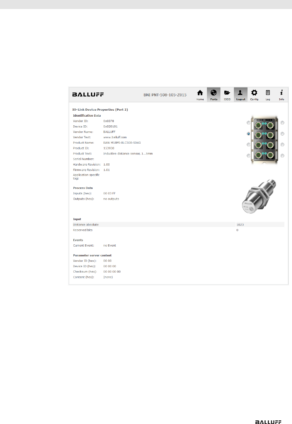
9 Web Server
Appropriate IODD
uploaded
If an IODD appropriate to the IO-Link device connected to the currently selected port has
been uploaded (see "Dialog "IODD"), the normal dialog for "Process Data" and "Parameters"
is not displayed, but rather an expanded dialog.
Information from the IODD of the device is used so that the data can be better understood.
Thus in the following screenshot not only are the input data of the distance sensor displayed
as a hex number, but also interpreted and labeled under "Input".
Since the sensor has no parameters, none are displayed.
Dialog "Ports“: IODD interpretation and device image
www.balluff.com
45
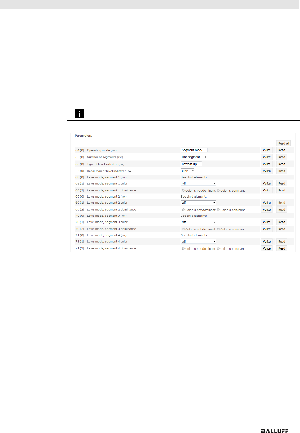
9 Web Server
If the IODD of the IO-Link device on the currently selected port has parameters, these are
shown in table format (see following screenshot). In this example the parameters for the Balluff
Smart Light are shown.
The Smart Light is a signal light which can be used in three different modes. These modes can
be set using an IO-Link parameter. The parameter values and associated texts are stored in
the IODD.
This means "Operation Mode" can be read out and displayed ("Read" and "Read All" buttons)
or written to the device ("Write" button).
If subindexes have no buttons they cannot be individually processed but rather only the entire
index at once.
Note
Each changed value must be individually written by clicking on the "Write" button!
"Ports" dialog: Parameter list of an IO-Link device with uploaded IODD
Balluff Network Interface EtherNet/IP™
www.balluff.com
46
9 Web Server
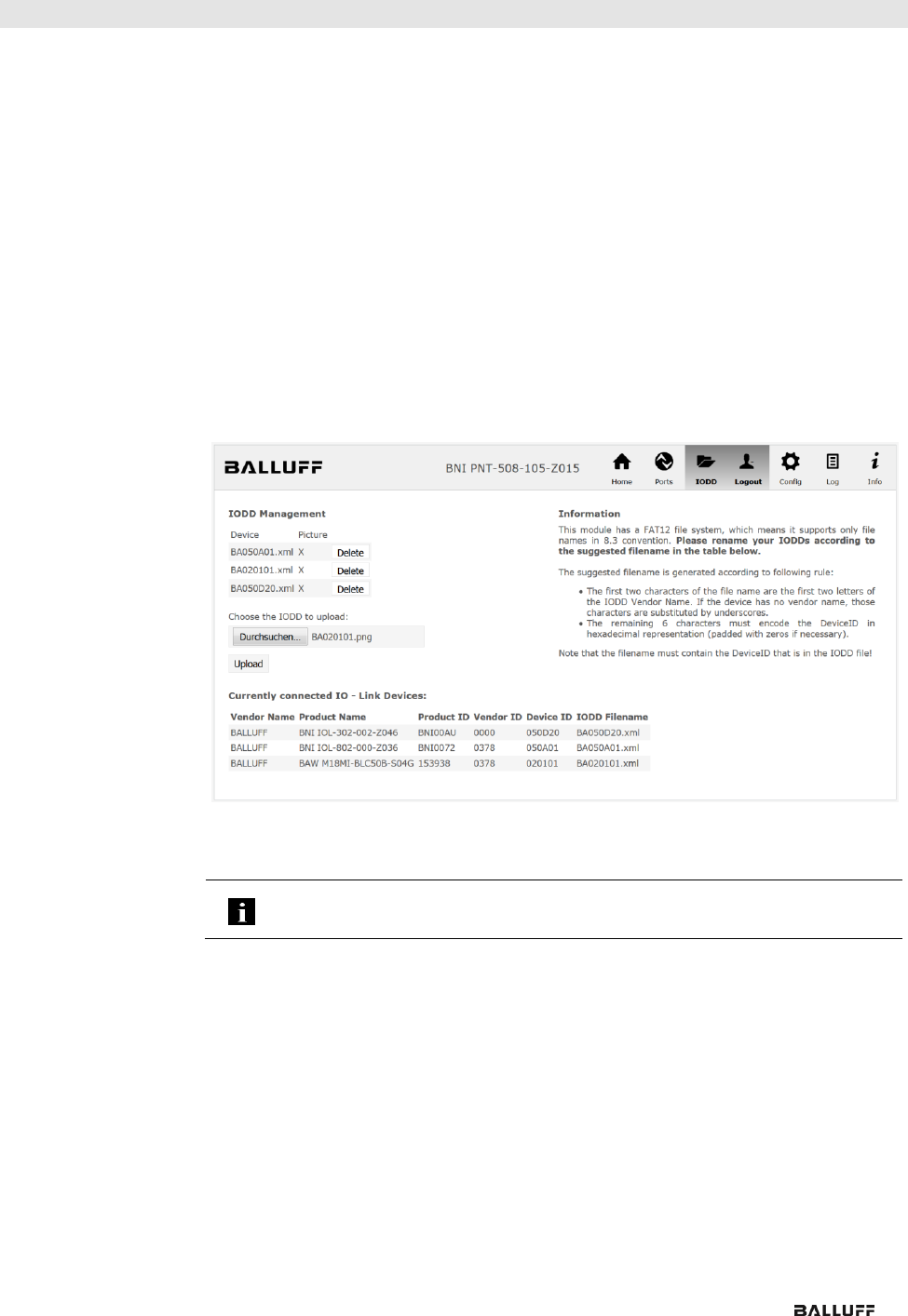
9.6. "IODD" dialog
Using this dialog you can transfer IODDs (device description files for IO-Link devices) and the
associated device images to the fieldbus module, so that a detailed representation of the
connected IO-Link devices in the "Ports" dialog is possible.
When IO-Link devices are connected and IO-Link ports are activated, the dialog shows a table
with information about the IO-Link devices.
The fieldbus module file system supports only device names in "8+3" format, i.e. with a
restricted name length. Since IODD files are generally published with a long file name, these
must be renamed and given a shorter naming scheme on the PC before uploading to the
fieldbus module.
For this a help setting is provided in the dialog, with the associated required IODD file name
for the currently connected IO-Link devices shown in the bottom section of the list (column
IODD Filename).
Image files without IODD can also be uploaded; the images are still displayed in the "Ports"
dialog.
Using the "Delete" button you can delete IODDs and device images from the fieldbus when
needed.
Note
Before selecting the IODD it must be renamed on the PC to the file name which is
shown in the table in the "IODD Filename" column!
www.balluff.com
47
9 Web Server
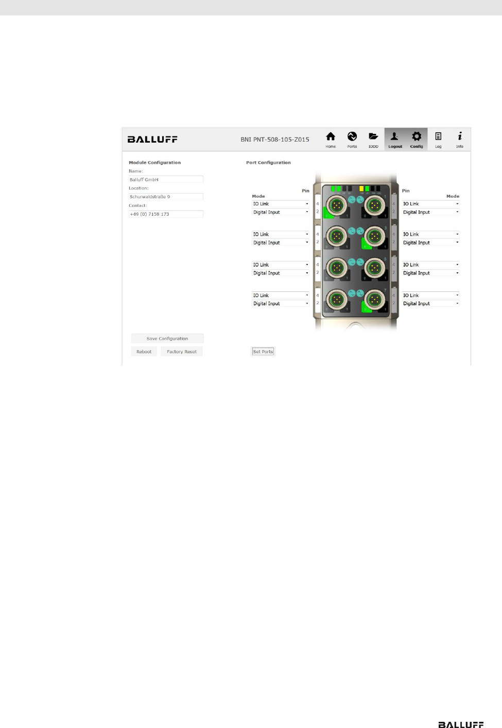
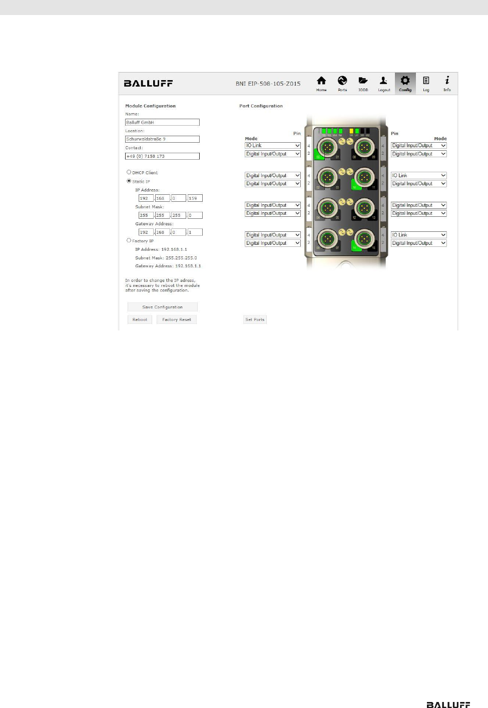
9.7. "Config" dialog
The configuration page enables configuration of the module. You can change both the
module information texts and the port configuration.
The "Set Ports" action is not permanently stored in the device and is lost after the next reboot
or reset.
PNT / ECT:
Balluff Network Interface EtherNet/IP™
www.balluff.com
48
9 Web Server
EIP:
The parameter set “Module Configuration” on the left side is used by clicking "Save
Configuration" and permanently stored in the device.
The "Reboot" button reboots the device as if the power to the module had been turned off
and on again.
Clicking on "Factory Reset" deletes the configuration and log files saved in the device and
then performs a reboot, so that the device is restored to the default factory configuration as
on delivery.
www.balluff.com
49
9 Web Server
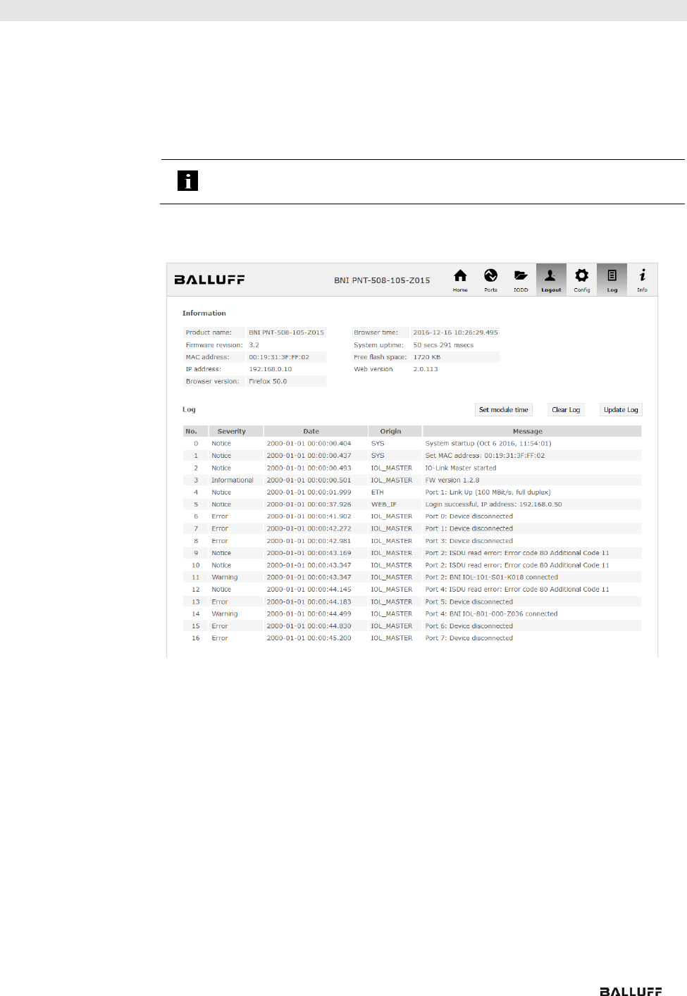
9.8. "Log" dialog
This dialog provides general service information about the device as well as a logging
function.
The upper table (see screenshot below) contains important information for all service
inquiries.
Note
If you have a detailed question about a specific situation, send us a screenshot of
this Website or print the site as a PDF.
Logging shows events which have occurred in chronological order. This provides a tool for
detailed troubleshooting in equipment.

Balluff Network Interface EtherNet/IP™
www.balluff.com
50
9 Web Server
Events are classified using the "Severity“ column:
Internal Error (Emergency, Alert, Critical)
The fieldbus module has detected a fault in itself (hardware or software) which should
not occur during normal operation. If this happens, the module must be serviced or
replaced.
External Error (Error, Warning)
The fieldbus module has detected what may be a non-permissible event which is
affecting the module from the outside. The system may require troubleshooting.
Event (Informational, Notice)
The fieldbus module has detected an important normal operating event and reports it. These
may include for example configuration actions over the web interface and other configuration
interfaces which are also recorded.
Clicking on "Set Module Time” sends the current browser time to the fieldbus module but
does not permanently store it. After a reset, reboot or loss of power the time begins to run
again from the year 2000.
Clicking on "Update Log” refreshes the display, and "Clear Log” deletes all entries. The log
entries are stored in a ring buffer.

www.balluff.com
51
10 Appendix
10.1. Scope of
Delivery
The BNI EIP comprises the following elements:
• IO-Link block
• 4x M12 dummy plugs
• Ground strap
• M4x6 screw
• 20 informational signs
10.2. Order Number
BNI EIP-50x-105-R015
Balluff Network Interface
Ethernet IP
Functions
502 = IP 67 IO-Link master module, 4 IO-Link ports
508 = IP 67 IO-Link master module, 8 IO-Link ports
Versions
105 = display version, 2-port switch
Mechanical version
R015 = plastic housing, resistant (Fortron 6165 A6 black)
Data transmission: 2 x M12x1 internal thread
Power supply: 7/8" external thread, 7/8" internal thread
Sensor connections: 8 x M12x1 internal thread
10.3. Ordering
Information
Product order code
Order code
BNI EIP-502-105-R015
BNI008Z
BNI EIP-508-105-R015
BNI008M

www.balluff.com
52
Notes

www.balluff.com
53
www.balluff.com
Balluff GmbH
Schurwaldstrasse 9
D-73765 Neuhausen a.d.F.
Germany
Phone +49 7158 173-0
Fax +49 7158 5010
balluff@balluff.de
No. 922508-726 E 04.124053 Edition D17 Replaces Edition B17 Subject to modification
