Manual LPS304
Manual_LPS304
Manual_LPS304
User Manual: Pdf
Open the PDF directly: View PDF ![]() .
.
Page Count: 17
LPS Series
Linear Power Supplies
OPERATION MANUAL
/METER INTERNATIONAL CORP.
6 Floor, No. 59, Tsao-Dih
Woei,
Wan Shun Liao, Shen Keng Hsiang,
Taipei Hsien, Taiwan, R.O.C.
Tel: 886-2-662-5093
~
5
l
886-2-662-5194
~
6
Fax: 886-2-662-5097

CONTENTS
ONE: GENERAL
INFORMATION
1.1
Introduction
1.2 Safety considerations
1.3
Accessories
1.4 Output Isolation
1.5 Specifications
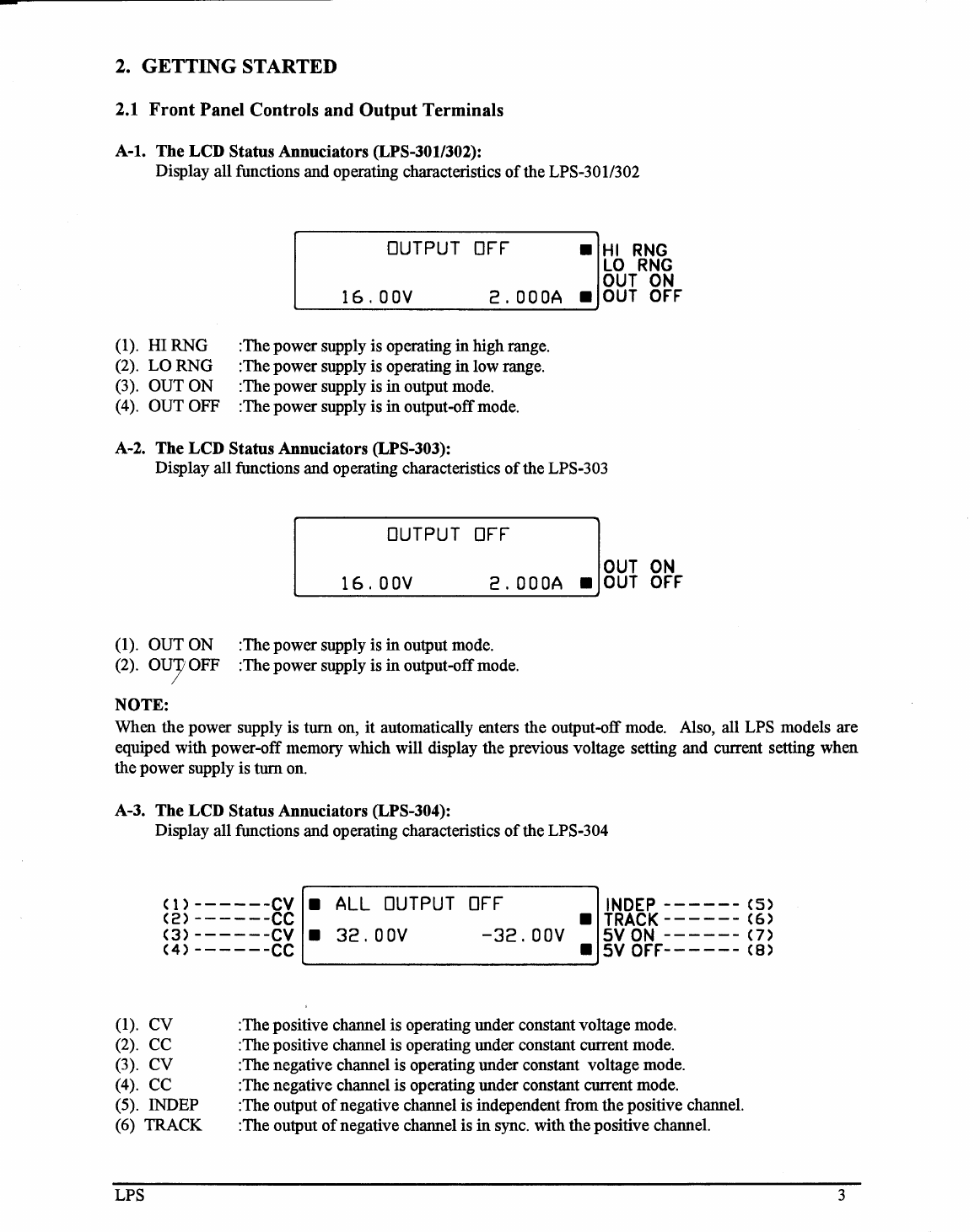
Two: GETTING STARTED
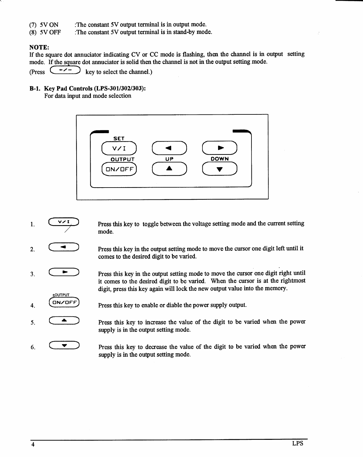
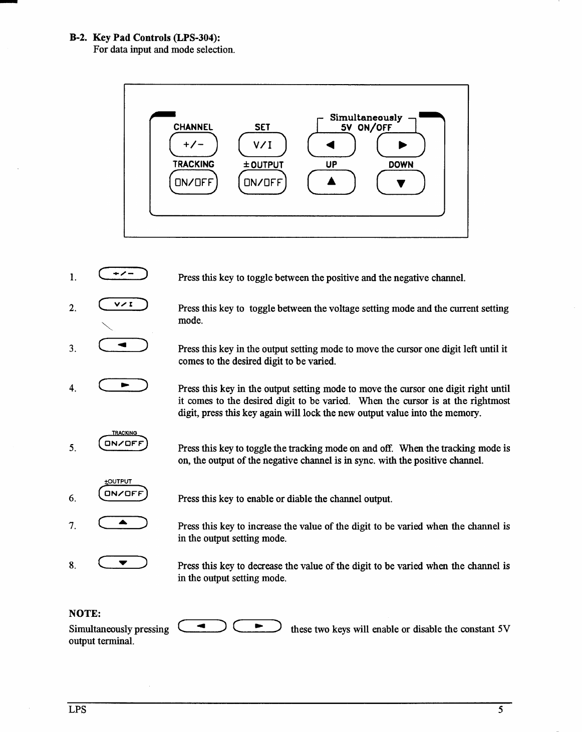
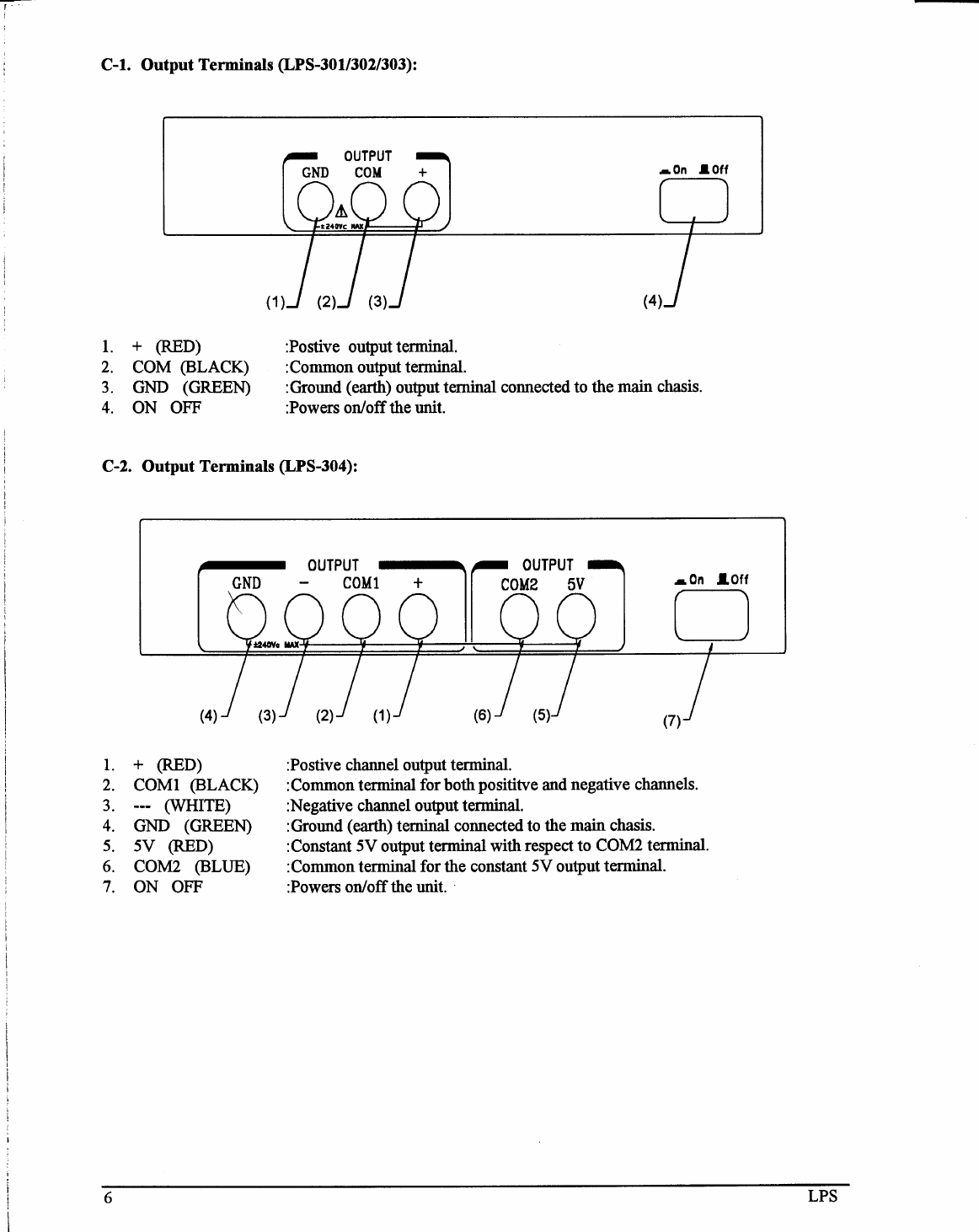
2.1 Fromt Panel Controls And Output Terminals
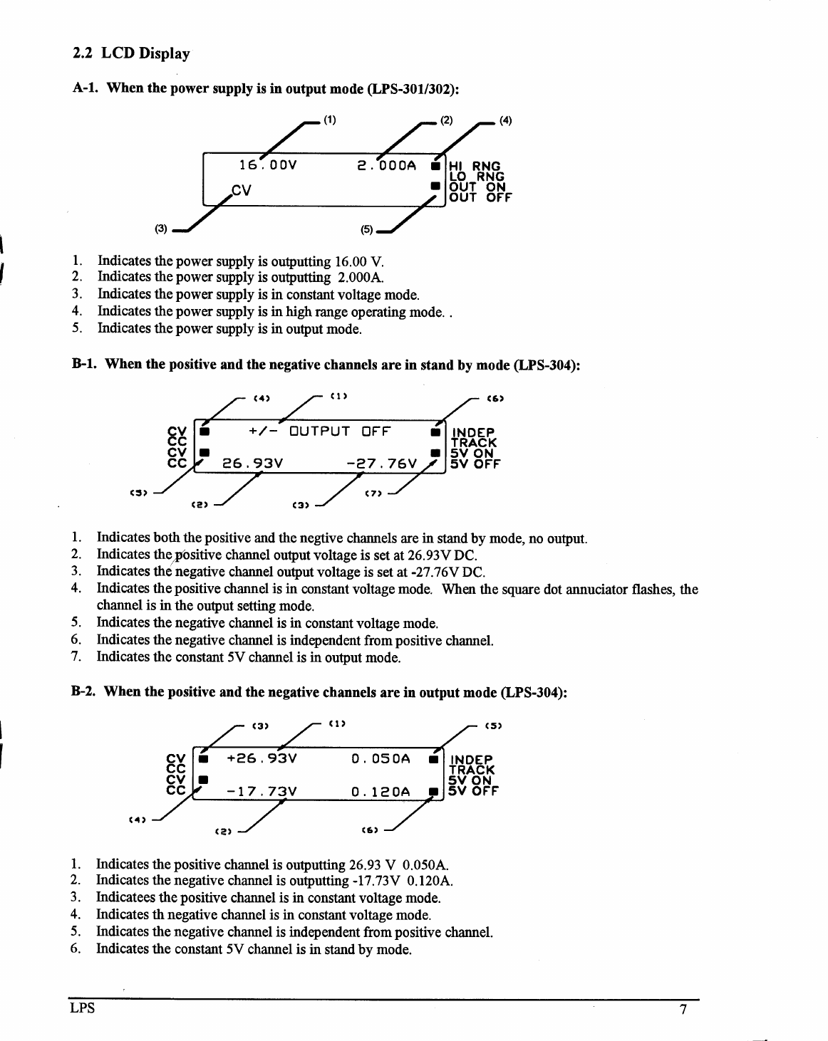
2.2 LCD Display
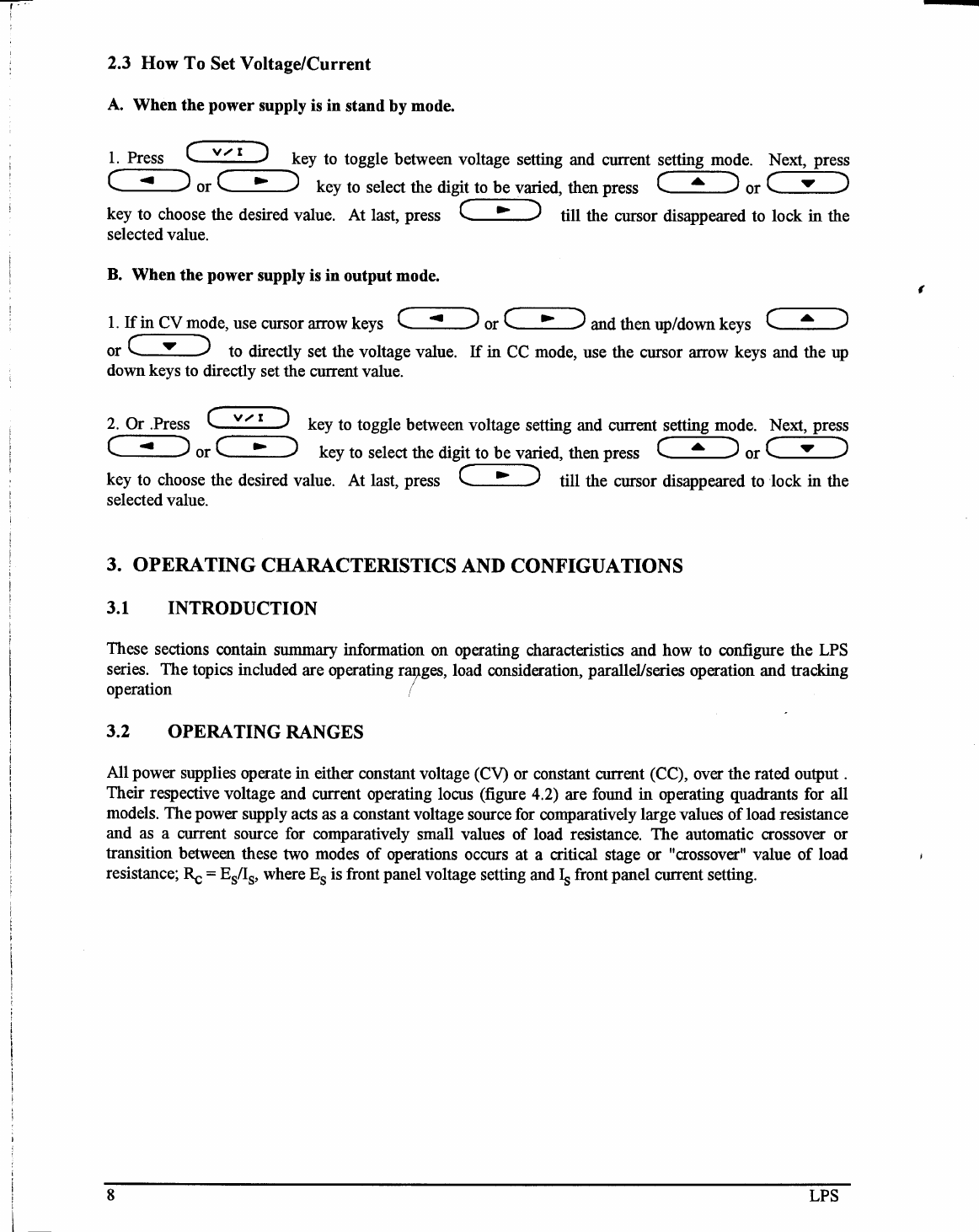
2.3 How To Set Voltage/Current
THREE: OPERATING CHARACTERISTICS AND CONFIGUATIONS
3.1 Introduction
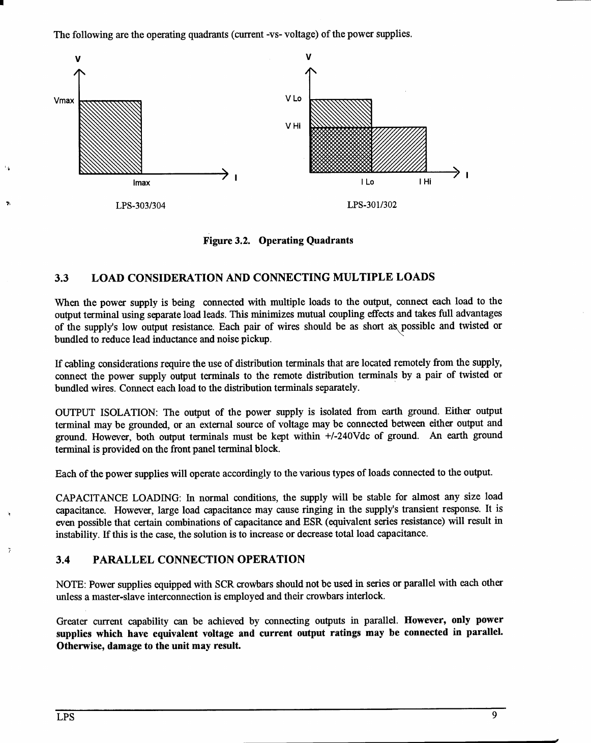
3.2 Operating Ranges
3.3 Load Consideration Connecting Multiple Loads
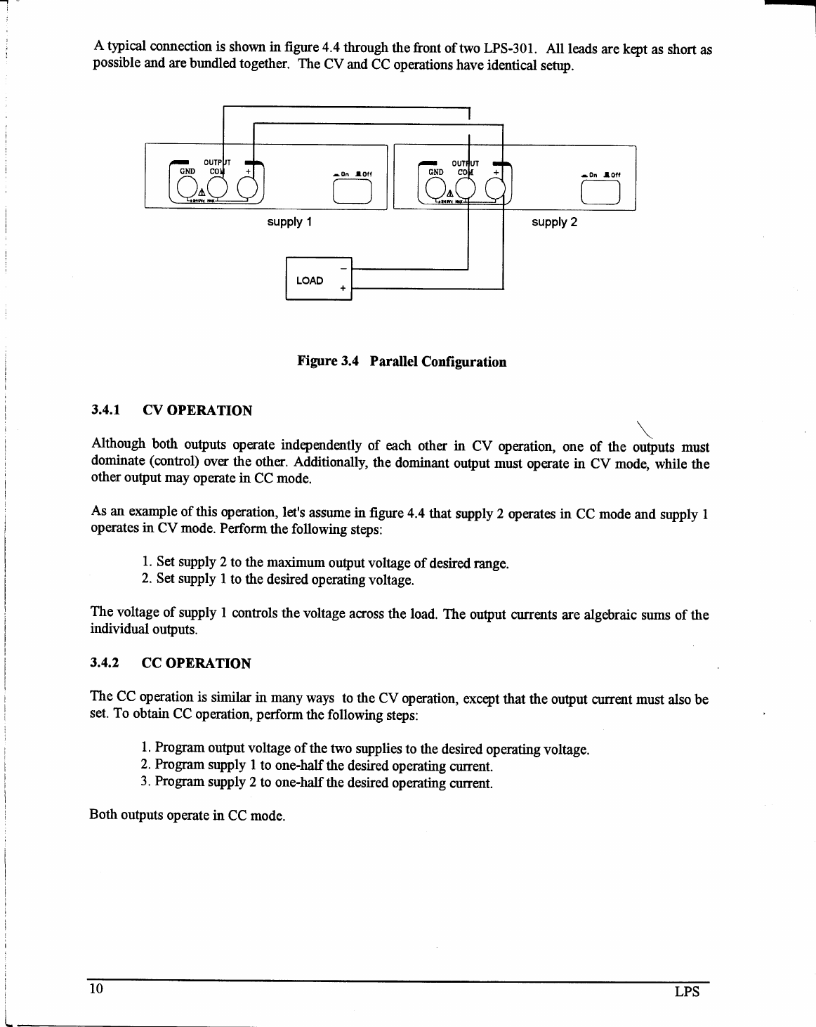
3.4 Parallel Connection Operation
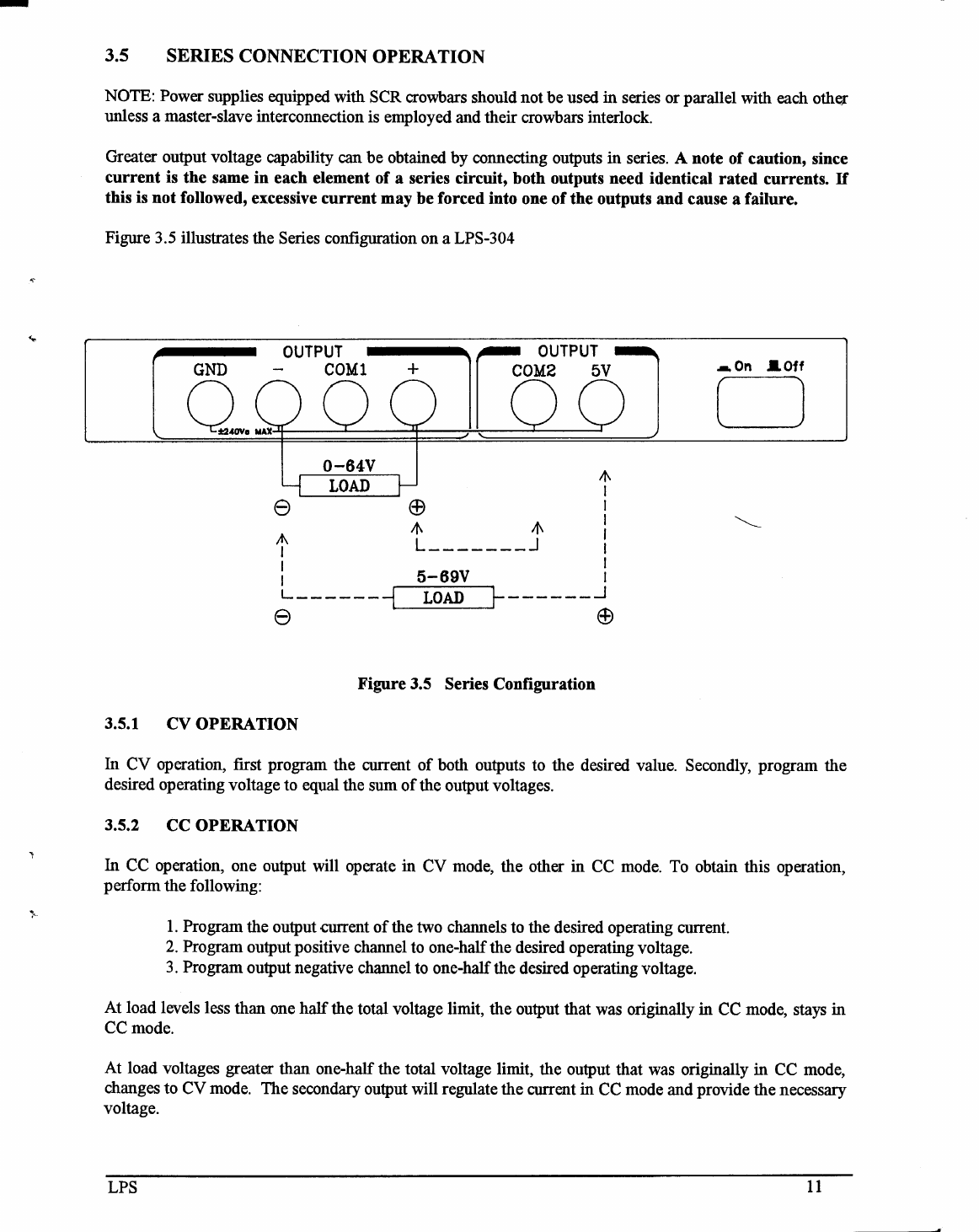
3.5 Series Connection Operation
3.6 Tracking Operation (LPS-304)
3.7 Range Operation (LPS-30
l/302)
FOUR: USER MAINTENANCE/SERVICE
4.1 Fuse Replacement
4.2 In Case Of Difficulties
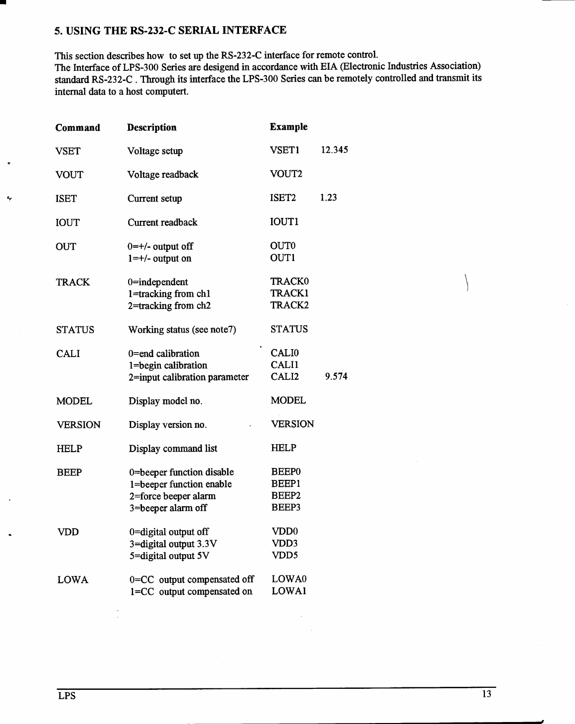
FIVE:
USING THE RS-232-C SERIAL INTERFACE

1. GENERAL INFORMATION
1.1 Introduction
This section contains a general description of your power supply as well as its performance specifications.
Information about options and accessories are also provided.
1.2 Safety Considerations
DO NOT EXCEED INPUT RATINGS
This instrument must be connected to a properly grounded receptacle to minimize electric shock hazard.
Operation
at line voltages or frequencies in excess of those stated on the data plate may cause leakage
currents in excess of 5.0mA peak.
SAFETY SYMBOLS
WARNING
The WARNING sign denotes a hazard. It calls attention to a procedure, practice,
or the like, which, if not correctly performed or adhered to, could result in
personal injury.
Do not proceed beyond a WARNING sign until the indicated
conditions are fully understood and met
CAUTION
A
The CAUTION sign denotes a hazard. It calls attention to a procedure, practice,
or the like, which, if not correctly performed or adhered to, could result in
damage to or destruction of part or all of the product.. Do not proceed beyond a
CAUTION sign until the indicated conditions are fully understood and met
1.3 Accessories
Power cable
Operation manual
Fuse
1.4 Output Isolation
The output of the power supply is isolated from earth ground. Either output terminal may be grounded or
the output may floated up to +/- 240 Vdc (including output voltage) from chassis ground
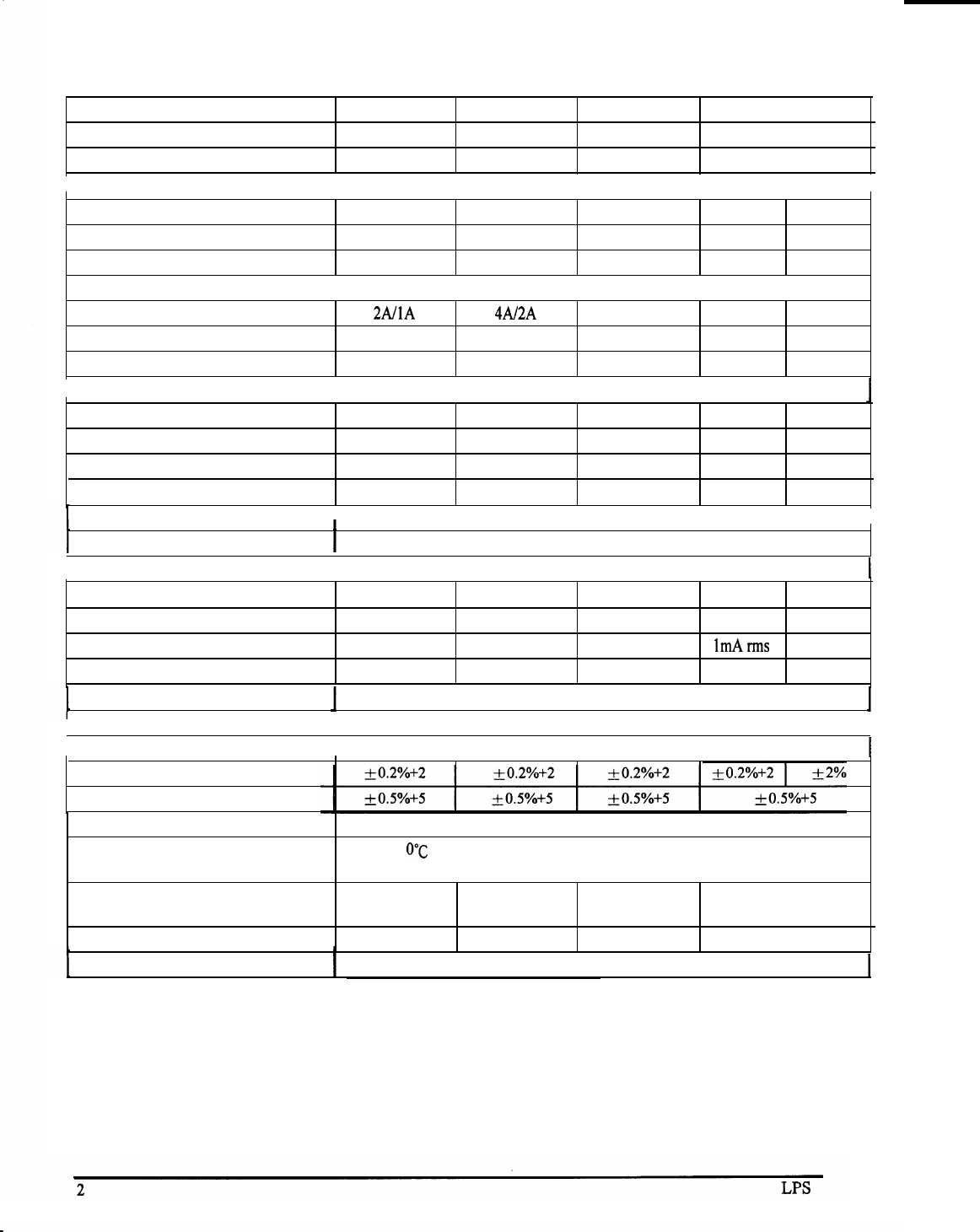
1.5 Specifications
Model
MAX. OUTPUT POWER
OUTPUTS
LPS301
30W
Single
LPS-302
60W
Single
LPS-303
90W
Single
LPS-304
70W
Triple
t
OUTPUT VOLTAGE
I
Output Voltage
Peak Output Voltage
Setting Resolution
30V/15V 30V/15V 3ov +/-30V
5V
32V/16V 32V/16V +/-32V
10mV 10mV 10mV 10mV
OUTPUT CURRENT
Output Current
Peak Output Current
Setting Resolution
2A/1A
4A/2A 2.5A 1A 2A
2.4A/l.2A
4.4A/2.2A 3A 1.2A
1mA 1mA
ImA
1mA
4
CONSTANT VOLTAGE CHARACTERISTICS
(at rated output)
Line Regulation (0% AC)
Load Regulation (100% load change)
Ripple/Noise rms (1 0Hz to 20MHz)
Ripple/Noise peak (1 0Hz to 20MHz)
1mV
2mV
1mV rms
1 0mV p-p
1mV
2mV
1mV
rms
10mV p-p
Transient Response 30ms
1mV
2mV
1mV rms
1 0mV p-p
,
I
1mV
5mV
2mV
1 0mV
1mV rms 2mV rms
10mV p-p 1 0mV p-p
Temperature Coefficient 1 00ppm/“c
CONSTANT CURRENT CHARACTERISTICS
(at rated output)
Line Regulation (0% AC) 2mA 2mA 2mA 2mA
Load Regulation (100% load change)
5mA
5mA 5mA 5mA
Ripple/Noise rms (1 0Hz to 20MHz) 1mA rms 1mA
rms
1mA rms
1
Ripple/Noise peak (1 0Hz to 20MHz)
5mA
P-P
5mA
P-P 5mA p-p
5mA
P-P
I
Temperature Coefficient 200ppm/C
OTHER
I
Display
I
16 character x 2 line backlit LCD
Voltage Accuracy
*
Current Accuracy
*
Common Mode Voltage
Temperature Range
40Vdc
Operating:
O’C
to 40°C , less than 80% RH; Storage: -45°C to 75°C , less than
80% RH
Dimensions
(WxHxL)
Weight
8.7”x 3.4”x
11.8”
10 lbs
8.7”x 3.4”x
11.8”
12 lbs
8.7”x 3.4”x
11.8”
12 lbs
8.7”x 3.4”x 11.8”
12 lbs
Cooling Forced Air
*For output less than 5% of rated output, add 5 digits to the accuracy specification
RS232 Interface: (optional)
1. RS232C DCE interface: 9
pin
D-SUB connector
2. Port configuration: asynchronous
2400 baud, 8 data bits, 1 stop bits, no parity

NOTE:
1. All RS232 command are case-nonsensitivity ASCII codes.
2. Use async framing 8 data bits, no parity bit
, l
stop bit.
3. Bit rate=2400bps
4. Every command string is terminated by CR or LF or BOTH (carriage return)
5. There is one command allowable in a command string
6. A command string enter before “OK” prompt will be reject
&
no function
7. STATUS opratin explanation:
After a LPS accept A “STAUS” command, it will display a decimal number in ASCII
Convert this decimal number to binary form. each bit indicate a action/status:
bit
0:
bit
1:
bit
3,2:
bit
4:
bit
5:
bit
6:
bit
7:
bit
bit
8:
9:
bit
10:
channel 1o=cv l=CC
channel 2o=cv l=CC
0O: independent
10: tracking
to channel 1
11
: tracking
to channel
2
0 : digital output off
1: digital output on
0: digtal output 5V
l:digital output 3.3V
O: output off
1: output on
0=nothing
1
=digital
output overload
O=fanoff
1=fan
on
O=beeper function disbale
l=beeper function enable
0=CC output compensated off
l=CC output compensated on

Calibration For LPS
301-304
Equipment needed for calibration: DMM, such as Fluke model 46 or HP 3479A
----
Step 1:
Simultaneously press
(
-v-/-1-
;and
i
v
i
keys to enter
.
\
-s-w
/
\
----
/
calibration mode.
Setp
2:
Measure the DC voltage from the positive channel output terminals
(+
and
COMl)
with DMM, and then use the arrow keys to enter the
measured value as the
+V
Lo,
Sept
3:
Repeat step 2. Enter the measured value as +V Hi.
Sept 4:
Measure the DC current from positive channel output terminals with
the DMM and enter the measured current value as
+I
Lo.
Sept 5:
Repeat step 4. Enter the measured value as +I Hi.
(For
LPS-304
Only)
Sept 6:
Measure the DC voltage from negative channel output terminals
(-
a;
COMl)
with the DMM, and enter the measured value as -V Lo.
Sept 7:
Repeat step
6.
Enter the measured value-
as -V
Hi.-------
---
Sept 8:
Measure the DC current from negative channel output terminals with
the DMM and enter the measured current value as -1 Lo.
Sept 9: Repeat step.
8.
Enter the measured value as -1 Hi. Calibration is
completed.'
NOTE: If Error #0002 appear on the LCD after inputting
ca1ibration
parameter
please make sure all the calibration parameters are correct-and the
re-enter them again.
