[MNC 300] FCC Ver
[Mnc-300] Fcc Ver [MNC-300]_FCC_ver [MNC-300]_FCC_ver CertsReports 550413 ProductFiles assets.mhint
2016-04-12
: Pdf [Mnc-300] Fcc Ver [MNC-300]_FCC_ver CertsReports 550406 ProductFiles
Open the PDF directly: View PDF ![]() .
.
Page Count: 27
Certification No. : LR500110806C
Verification
With The 47 CFR, Part2 and Part15
Of FCC Requirement
Hereby certifies that
Type of Product: Dome Network Camera
(Class A digital devices)
Model No.: MNC-300
Manufactures and address
MicroWeb Co., Ltd.
909 Kranz Techno Bldg., 5442-1 Sangdaewon-dong, Jungwon-gu,
Seongnam-si, Gyeonggi-do, 462-729 Korea.
This document is the proof that above product, system, and also relates OEM models are complying with FCC
requirement. We, LTA Co., Ltd is the accredited EMC laboratory for NVLAP(US), RRL(KOREA).
We certify that the above products had performed test on our laboratory and it was confirmed to comply with
FCC requirement. These products might be marketed at the US accordance to DoC of FCC Rule based on the
standard 47CFR Part 2 and 15. The test was performed accordance to the procedures from ANSI C63.4-2003.
Test data and results are issue on the EMC test report No. as follows.
Reference Endorsed Test Report No. is LR500110806C
Date: June 13, 2008
NVLAP LAB Code.: 200723-0
Dong –Min JUNG, Technical Manager
LTA Co., Ltd.
Certification No. : LR500110806C
Copyright © 2008, LTA CO., LTD. Page 1 of 26
TEST REPORT
Test Report No. : LR500110806C
Issue Date : June 13, 2008
Applied Standard : FCC Part 15, Subpart B
Trade Name : MicroWeb Co., Ltd
Category : Dome Network Camera
(Class A digital devices)
Model Name : MNC-300
Serial Number : Identification
This test result only responds to the tested sample. It is not allowed to copy this report even partly
without the allowance of the test laboratory. This report must not be used by the applicant to claim
product endorsement by NVLAP or any agency of the U.S. Government.
This laboratory is accredited by Radio Research Laboratory
and National Voluntary Laboratory Accreditation Program.
The tests reported herein have been performed in accordance with
its terms of accreditation.

Certification No. : LR500110806C
Copyright © 2008, LTA CO., LTD. Page 2 of 26
TABLE OF CONTENTS
★★★★★★★★★★★★
Text Page
Contents ---------------------------------------------------------------------------------------------------------- 2
LTA Certification ----------------------------------------------------------------------------------------------- 3
General Information ----------------------------------------------------------------------------------------------- 6
Brief Information --------------------------------------------------------------------------------------------------- 7
Test site description -------------------------------------------------------------------------------------------------- 10
Test Procedure ------------------------------------------------------------------------------------------------------ 11
List of test equipment used for the test ----------------------------------------------------------------------- 13
Radiated disturbance measurement --------------------------------------------------------------------------- 14
Result & Graph
Conducted disturbance measurement ------------------------------------------------------------------------- 15
Result & Graph
Conclusions --------------------------------------------------------------------------------------------------------- 17
Photograph of the measurements ------------------------------------------------------------------------------- 18
Photograph of the EUT ------------------------------------------------------------------------------------------ 20
★★★★★★★★★★★★

Certification No. : LR500110806C
Copyright © 2008, LTA CO., LTD. Page 3 of 26
LTA Certification
Client / Factory
Company name : MicroWeb Co., Ltd.
Address : 909 Kranz Techno Bldg., 5442-1 Sangdaewon-dong, Jungwon-gu,
Seongnam-si, Gyeonggi-do, 462-729 Korea.
Telephone / Facsimile : +82-31-735-7200 / +82-31-735-7600
Equipment Under Test (EUT)
Trade name : MicroWeb Co., Ltd.
Category : Dome Network Camera
(Class A digital devices)
Brand : Webview
Model name : MNC-300
Additional Model name : -
Serial number : Identification
Date of receipt : May 19, 2008
EUT condition : Pre-production, not damaged
Interface port : LAN, MIC, IR, POWER, BNC
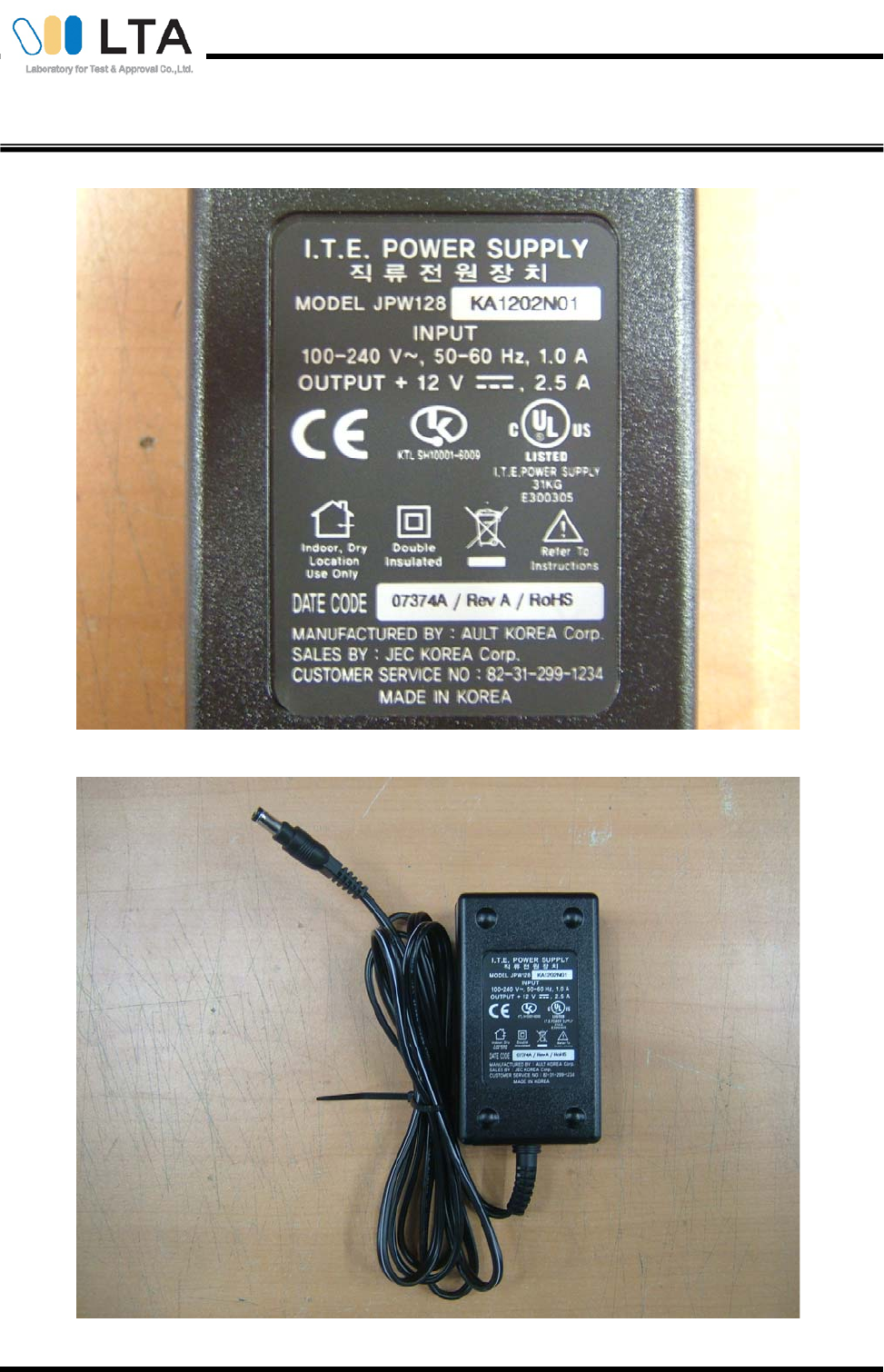
Power Source : INPUT : 100-240v, 50-60Hz, 1.0A
OUTPUT : 12V, 2.5A
Test memory Size : -
Operating mode : Web camera + Ping mode
Crystal/Oscillator(s) : Main : 14.318180 MHz, 28.750BMHz, 2.048BMHz, 10AMHz, 25MHz
Sub : 28.375MHz, 27 MHz
*** To be continued next page***
Certification No. : LR500110806C
Copyright © 2008, LTA CO., LTD. Page 4 of 26
LTA Certification-cont.-
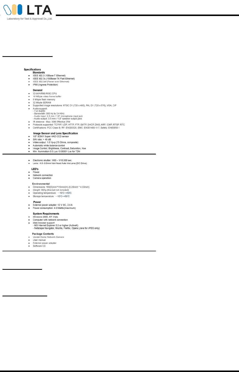
Model Specification
Test Performed
Test started & completed : May 19 ~ 23, 2008
Location : LTA Co., Ltd.
Test Specification
Purpose of the test : Compliance test to the following standard
Applied standard : FCC Part 15, Subpart B
Classification : Class A
Deviations from Standard
Test Method : N/A
*** To be continued next page ***
Certification No. : LR500110806C
Copyright © 2008, LTA CO., LTD. Page 5 of 26
LTA Certification-cont.-
Test Results
Measurement Results* Test method
Radiated disturbance Complies ANSI C 63.4:2003
Conducted disturbance Complies ANSI C 63.4:2003
* : The compliance statement is based on nominal value only.
Modification performed by the lab.;
- N.A
Laboratory’s Certificate
Report number : LR500110806C
Issue date : June 13, 2008
This test report is issued under the authority of: The test was supervised by:
Dong –Min JUNG, Technical Manager Bok – Soo KIM, Test Engineer
The results in this report apply only to the sample(s) tested.
It is not allowed to copy this report even partly without the allowance of the test laboratory.
Certification No. : LR500110806C
Copyright © 2008, LTA CO., LTD. Page 6 of 26
General information’s
Purpose
This document is based on the Electromagnetic Interference (EMI) tests performed on the “MNC-300”. The
measurements were performed according to the measurement procedure described in ANSI C 63.4:2003. The
tests were carried out in order to confirm whether the electromagnetic emissions from the EUT( Equipment Under
Test), are within the class A limits defined in FCC Part 15, Subpart B- “Section 15.107- Conducted limits” and
“Section 15.109-Radiated emission limits”.
Test Performed
Company name : LTA Co., Ltd.
Address : 243, Jubug-ri,Yangji-Myeon,Youngin-Si, Kyunggi-Do, Korea. 449-822
Telephone : +82-31-323-6008
Facsimile +82-31-323-6010
Measurement uncertainty
Radiated disturbance (30 – 1000MHz) : +4.52 [dB] ,-4.43 [dB] (k=2)
Conducted disturbance (0.15 – 30MHz) : +0.11 [dB] ,-0.11 [dB] (k=2)
The coverage factor k=2 yields approx. a 95% level of confidence for near-normal distribution typical of most measurement results.
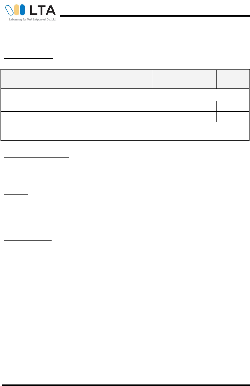
Accredited agencies
LTA Co., Ltd. Is approved to perform EMC testing by the following agencies:
Agency Country Accreditation No. Validity Reference
NVLAP U.S.A 200723-0 2008-09-30 ECT accredited Lab.
RRL KOREA KR0049 2009-06-20 EMC accredited Lab.
FCC U.S.A 610755 2011-04-22 FCC filing
VCCI JAPAN R2133, C2307 2011-06-22 VCCI registration
IC CANADA IC5799A-1 2010-05-23 IC filing
Certification No. : LR500110806C
Copyright © 2008, LTA CO., LTD. Page 7 of 26
Brief Information
1-1 Test Summary
Parameter Applied Standard Status
(note 1)
I. Emission
Radiated disturbance FCC Part 15.109 C
Conducted disturbance FCC Part 15.107 C
Note 1: C=Complies NC=Not Complies NT=Not Tested NA=Not Applicable
* The data in this test report are traceable to the national or international standards.
Frequency range to be scanned:
0.15 MHz - 30 MHz as conducted measurement
5th harmonic of the highest frequency or 40 GHz, whichever is lower
Bandwidth:
Measured by the CISPR quasi-peak function Bandwidth is 10kHz in the frequency 0.15MHz to 30MHz and 120kHz in
the frequency 30MHz to 1,000MHz.
Measured by the CISPR Peak function Bandwidth is 1MHz in the frequency 1GHz to 40GHz.
A sample calculation:
COR. F (correction factor)= Antenna factor + Cable loss- Amp.gain- Distance correction
Emission Level= meter reading + COR.F
Certification No. : LR500110806C
Copyright © 2008, LTA CO., LTD. Page 8 of 26
1-2 Operating Mode of the EUT
The tests have been conducted with the following operational mode(s) of the EUT.
Name of mode in the report Description
Web camera + Ping -
1-3 Modification
- None
1-4 List of EUT and accessory
EUT
Category Model Name Serial No. Manufacturer Remarks
Dome Network Camera MNC-300 N/A MicroWeb Co., Ltd. -
ACCESSORY
Category Model Name Serial No. Manufacturer Remarks
PC HP Compaq dx2200
Microwtower CNG6500WPK HP -
Monitor VS11353 E060T0404 VIEWSONIC -
Keyboard SK-8115 641-OEW DELL -
Mouse M056UOA FOJOONOL DELL -
Printer DESKJET 600K SG7631B1XX HP -
TV Monitor N/A N/A N/A -
Certification No. : LR500110806C
Copyright © 2008, LTA CO., LTD. Page 9 of 26
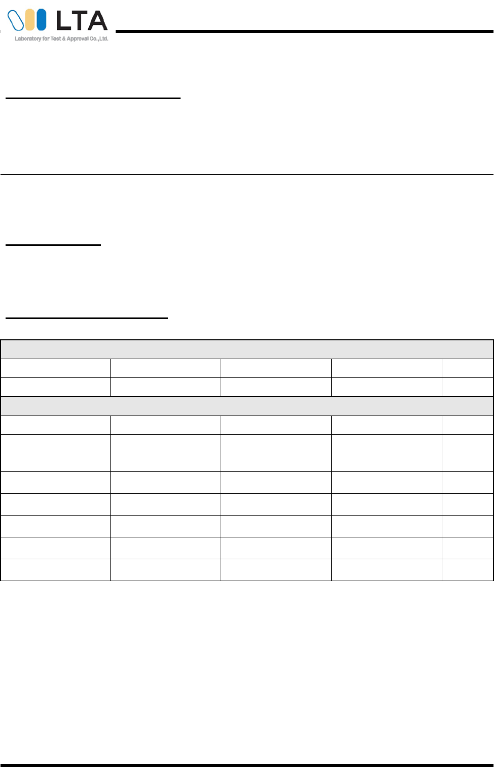
1-5 Cable List
Cable List
Remarks
Type Length
Shielding
(Cable/backshell) From to
ADAPTER 1.70 YES / NO DC ADAPTER
LAN 5.70 YES / NO LAN LAN
MIC 0.95 NO / NO MIC MIC
IR 1.45 NO / NO IR IR
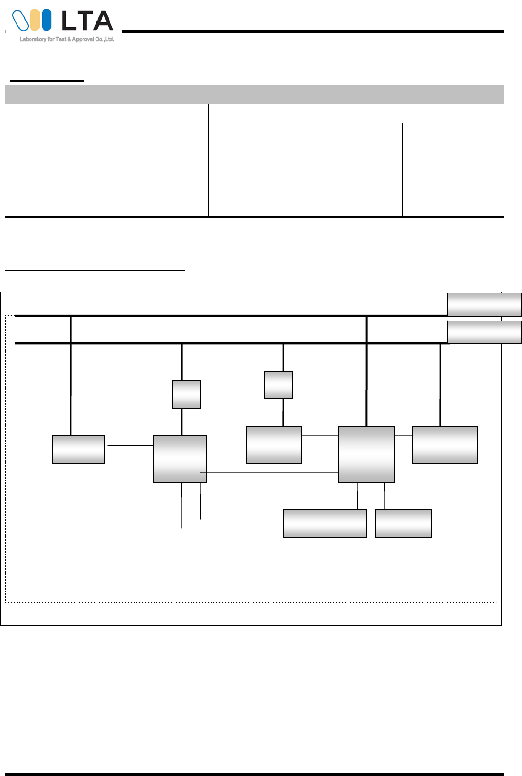
1-6 Block diagram of the EUT test
A : Adapter
Note) refer to the Test setup photograph.
Keyboard
Printer
EUT Monitor PC
Mouse
A
TV
A
3 Pin AC Line
2 Pin AC Line
Certification No. : LR500110806C
Copyright © 2008, LTA CO., LTD. Page 10 of 26
2- Test Site Description
1-Facility
All the testing facilities are periodically serviced as a daily check for equipment and cables systems, an every 6
months facility check for the facilities and a monthly check and annual calibration for testing equipment according
to ISO/IEC 17025. All the testing facilities are used as the same specifications shown below. There are descriptions
both for radiated disturbance measurement and conducted disturbance measurement conformed by ANSI C
63.4:2003.
The NSA measurement of the OATS was performed on Feb 8, 2008 according to ANSI C63.4 : 2003.
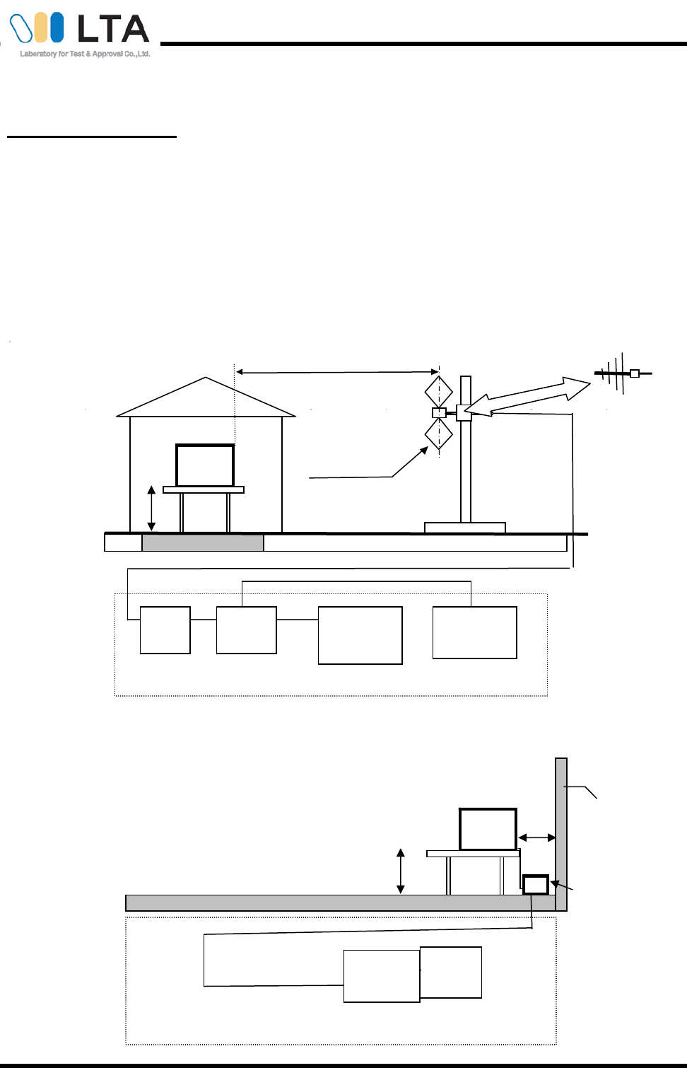
2-1 Radiated Disturbance Measurement
2-2 Conducted Disturbance Measurement
EUT
Turn Table Metal Ground Plane Size(7.2mx16m~7.2mx40m)
Antenna to ground
distance 1m to 4m
A
ntenna to EUT Distance 10m
Amplifier
Switch
Coaxial
Spectrum
Analyzer
EMI Receiver
Biconical Antenna
Log-periodic
A
ntenna
EUT Room
change the Antenna with each frequency
connections for equipment
0.8m
Horizontal ground Plane
Pulse limitor
EMI
Receiver
AMN
Bonded to
horizontal
ground plane
connections for equipment
EUT
0.8m
Vertical ground Plane
0.4m

Certification No. : LR500110806C
Copyright © 2008, LTA CO., LTD. Page 11 of 26
3- Test Procedure
3-1 Radiated Disturbance Measurements
・Test site is met the requirements of ANSI C 63.4:2003 and the distance between the EUT and the
antenna is adjusted 3m.
・The turntable can be rotated 360 degrees.
・The antenna can be adjusted between 1m and 4m in height above the ground.
・The EUT is placed on the non-conducting table with 0.8m height on the turntable.
・Measurements are carried out using a spectrum analyzer with peak detectors (100kHz bandwidth) and
an EMI receiver with quasi-peak detectors(120kHz bandwidth).
・Refer to the list of test equipment used for the test.
・TRILOG antenna are used as wideband antenna.
・The TRILOG antenna is used in the frequency range of 30MHz to 1000MHz, the Horn antenna is used in the
frequency range of 1GHz to 13GHz.
・A variable attenuator is used for verifying amplifier’s linearity.
・Rotating the turntable and adjusting the height of the antenna are carried out by control buttons on the console.
・Refer to "Brief Information"(page 5-8) about details of the EUT and configuration of the cables.
・Measurement is carried out by a LTA operator as manual operation.
–searching for some of High disturbance frequency points than the other points with the following settings;
bandwidth 100kHz, frequency range 10MHz between 30MHz and 300MHz and frequency range 50MHz
between 300MHz and 1GHz.
–searching the worst direction with the maximum level of the disturbance wave in rotating the turntable
360 degrees at each searched frequency point.
–setting the height of the antenna with the maximum level of the disturbance wave from 1m to 4m.
–reading the disturbance level by the EMI receiver with quasi-peak detectors (120kHz bandwidth)
according to ANSI C 63.4:2003.
–measuring to vertical and horizontal polarization.
–calculating the measurement result with the following formula or equation:
(Measurement result= measured value + antenna factor + antenna cable loss)

Certification No. : LR500110806C
Copyright © 2008, LTA CO., LTD. Page 12 of 26
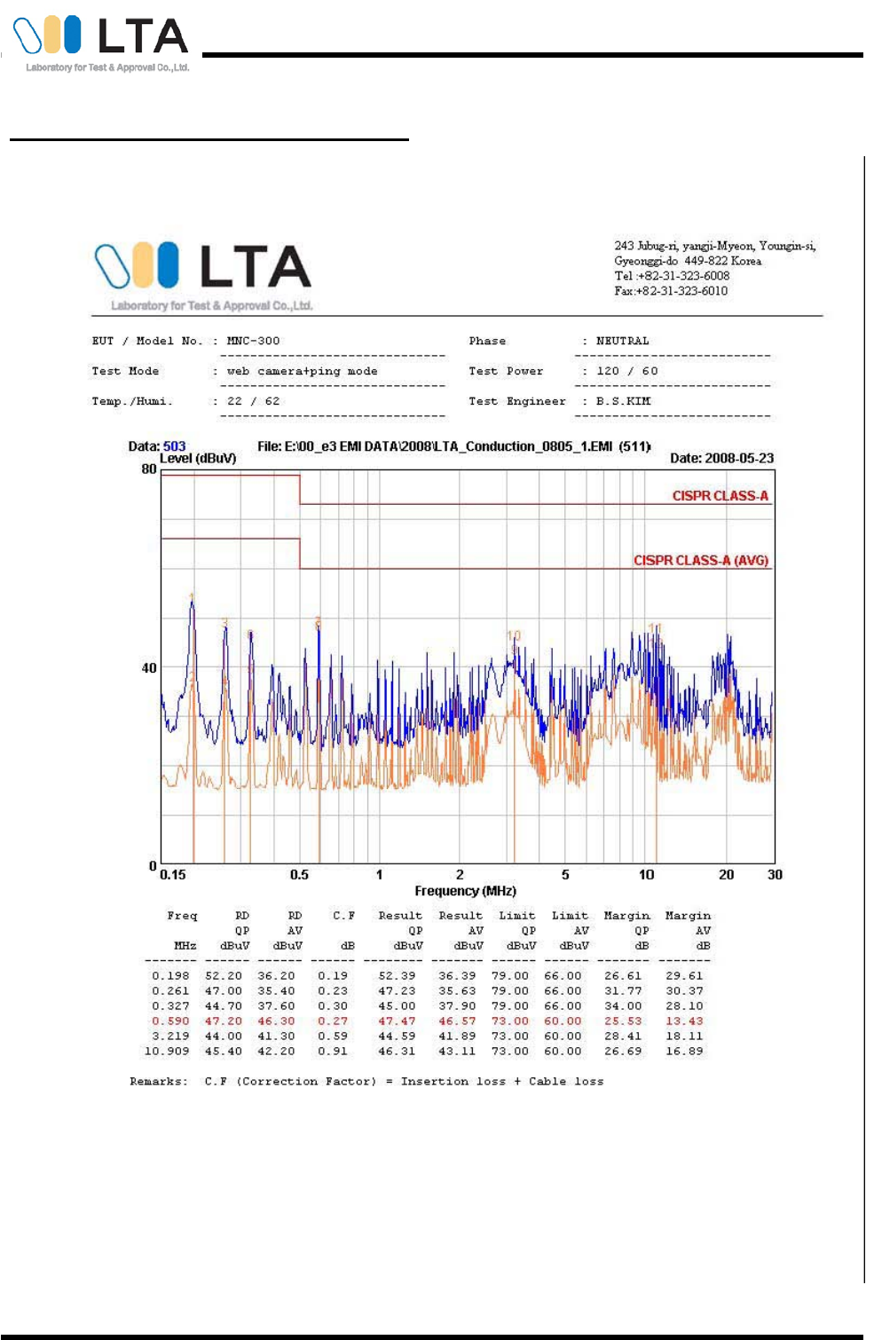
3-2 Conducted Disturbance Measurements
・The measurement is carried out on an open site with horizontal and metallic ground plane.
・An AMN(Artificial Mains Network) with a nominal impedance (50Ω/50μH) as defined
in ANSI C 63.4:2003, shall be utilized.
・The AMN is grounded on a horizontal metal ground plane.
・Measurement is carried out using an EMI receiver with quasi-peak detectors and average detector.
(Refer to the List of test equipment used for the test.)
・The shortest distance between the EUT and the AMN is 0.8m.
・The EUT is placed on the non-conducting table with 0.8m height.
・A remote switch is used for changing phases between Line (L) and Neutral (N).
・Refer to "Brief Information"(page 5-8 ) about details of the EUT and configuration of the cables.
・Measurement is carried out as manual operation.
–detecting the maximized emission level using the maxhold function after setting the spectrum
analyzer bandwidth 1MHz and the frequency range from 150kHz to 1MHz , 1MHz to 5MHz and 5MHz
to 30MHz.
–searching the maximum frequency point of the disturbance wave in each frequency range.
–reading the disturbance level of quasi-peak, average and Line (L) and Neutral (N) in 9kHz bandwidth
by the EMI receiver.
–calculating the measurement result with the following formula or equation.
(Result = Reading + Cor.F.)
(Margin = Limit- Result)
Certification No. : LR500110806C
Copyright © 2008, LTA CO., LTD. Page 13 of 26
4- List of Equipment Used For the Tests
Item Model Name Serial No. Manufacturer Interval Last Cal.
1 Spectrum Analyzer 8594E 3624A03247 HP 1 year Oct-12-07
2 Test Receiver ESHS10 828404009 R&S 1 year Aug-24-07
3 Two-Line V-Network ENV216 100408 R&S 1 year Dec-07-07
4 Two-Line V-Network ESH3-Z5 893045/017 R&S 1 year Oct-12-07
5 EMI Test Receiver ESVD 843748/001 R&S 1 year Aug-24-07
6 Spectrum Analyzer 8591E 3649A05888 HP 1 year Oct-12-07
7 RF Amplifier 8447D 2949A02670 HP 2 year Jan-25-07
8 RF Amplifier 8447D 2439A09058 HP 1 year Oct-12-07
9 TRILOG Antenna VULB9160 9160-3212 SCHWARZBECK 2 year Jul-05-06
10 RF Switch MP59B 6200414971 ANRITSU 2 year May-28-07
11 Splitter ZFM-150 15542 Mini-Circuits 1 year Apr-02-08
12 RF Amplifier 8449B 3008A02126 HP 1 year Apr-03-08
13 Horn Antenna 3115 00055005 ETS 2 year Mar-15-07
Certification No. : LR500110806C
Copyright © 2008, LTA CO., LTD. Page 14 of 26
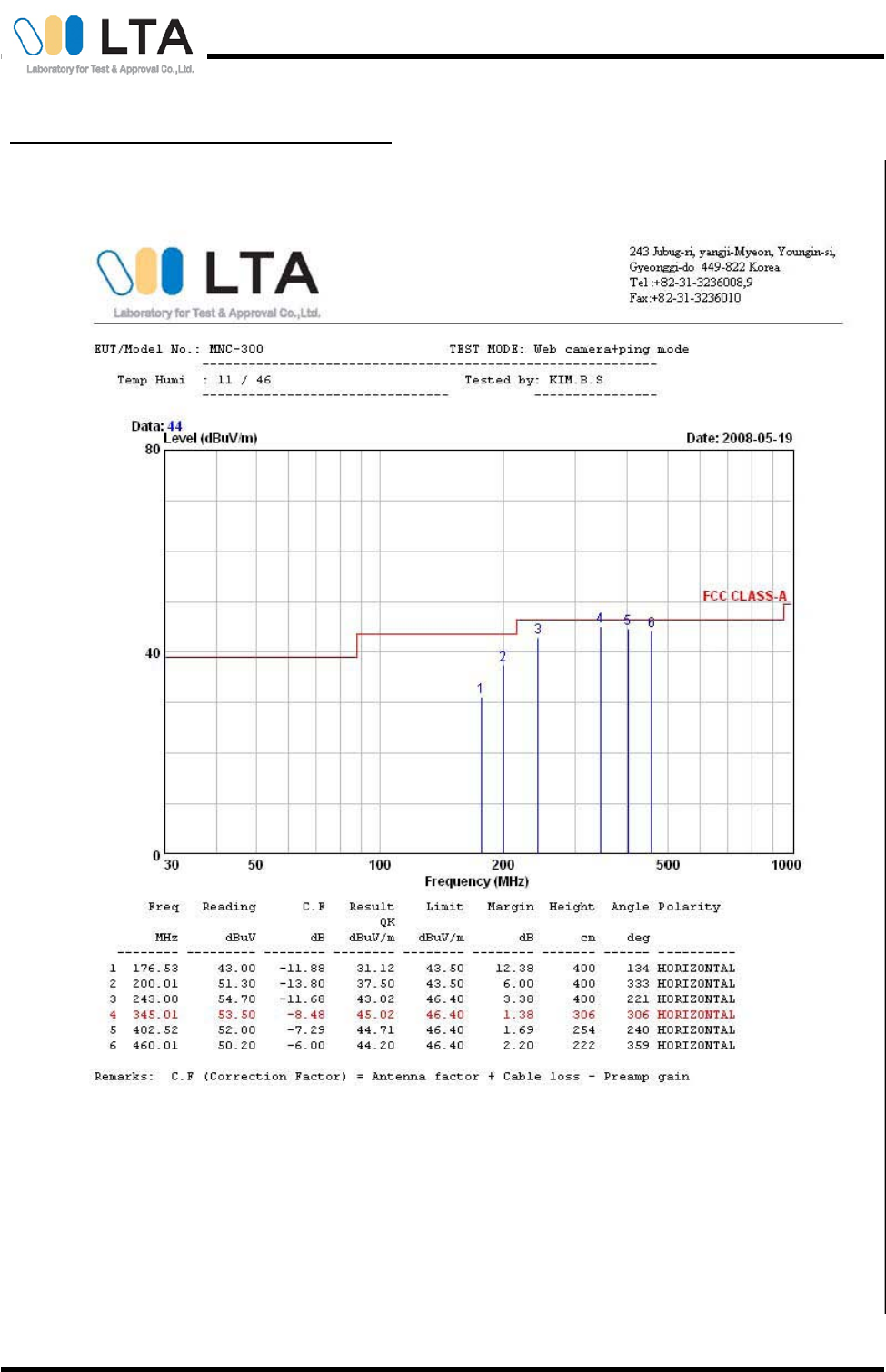
5-1 Radiated Disturbance Measurements
Certification No. : LR500110806C
Copyright © 2008, LTA CO., LTD. Page 15 of 26
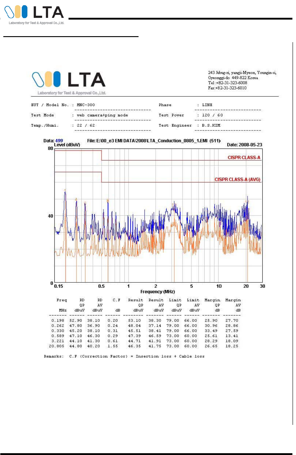
5-2 Conducted Disturbance Measurements
Certification No. : LR500110806C
Copyright © 2008, LTA CO., LTD. Page 16 of 26
5-2 Conducted Disturbance Measurements - Continue

Certification No. : LR500110806C
Copyright © 2008, LTA CO., LTD. Page 17 of 26
Conclusions
Product models " MNC-300 " meets all of the Class A requirements of the FCC Part 15, Subpart B. (Limits of radio
disturbance characteristics of ITE).
( Refer to Test Specification and Test Results in the "LTA certification", page3.)
Certification No. : LR500110806C
Copyright © 2008, LTA CO., LTD. Page 18 of 26
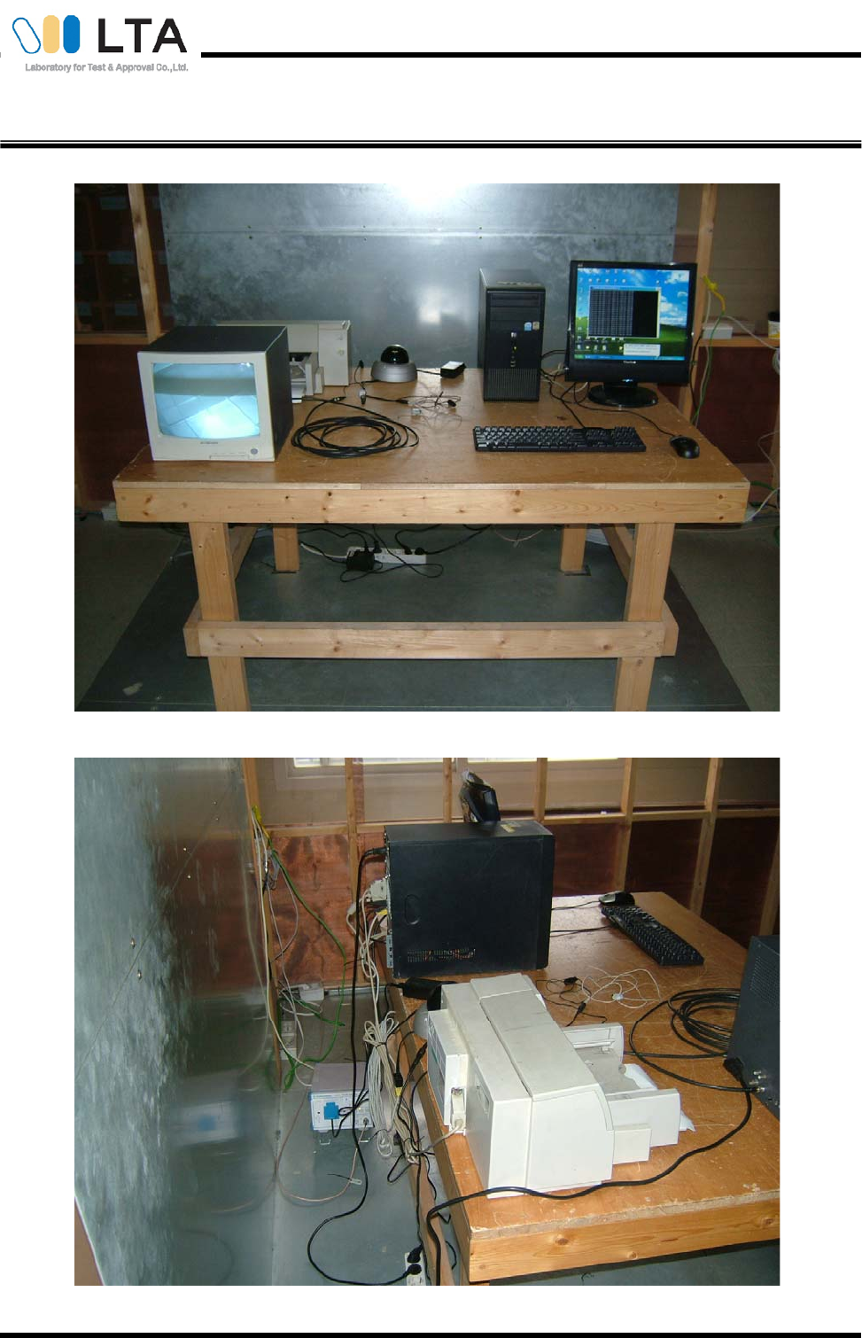
Photograph of the Radiated Disturbance Measurements
Certification No. : LR500110806C
Copyright © 2008, LTA CO., LTD. Page 19 of 26
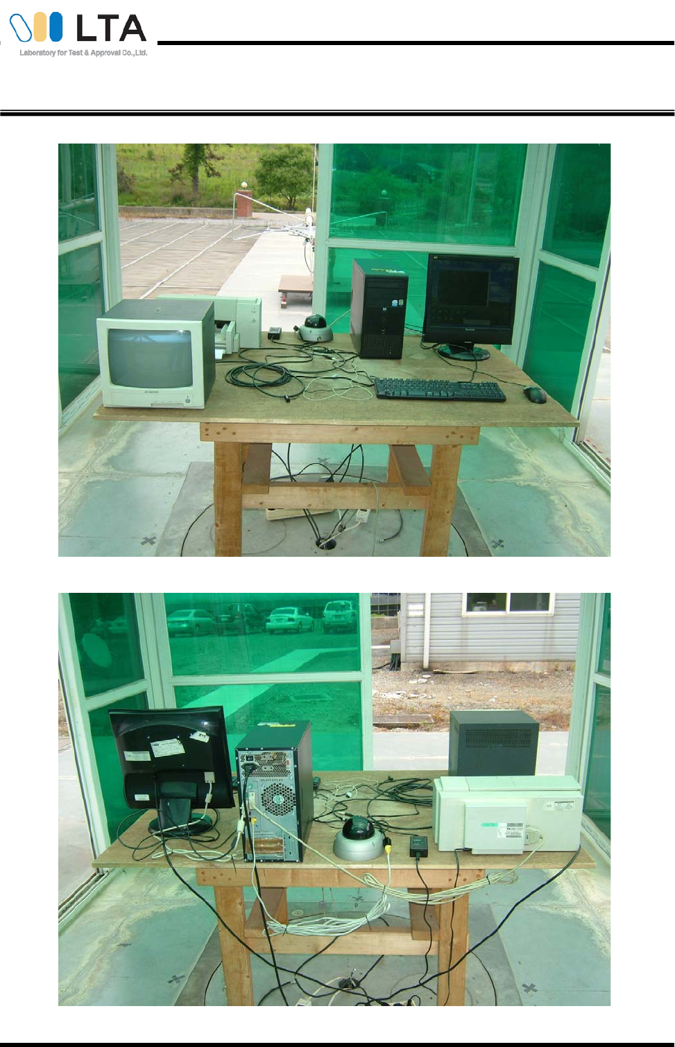
Photograph of the Conducted Disturbance Measurement
Certification No. : LR500110806C
Copyright © 2008, LTA CO., LTD. Page 20 of 26
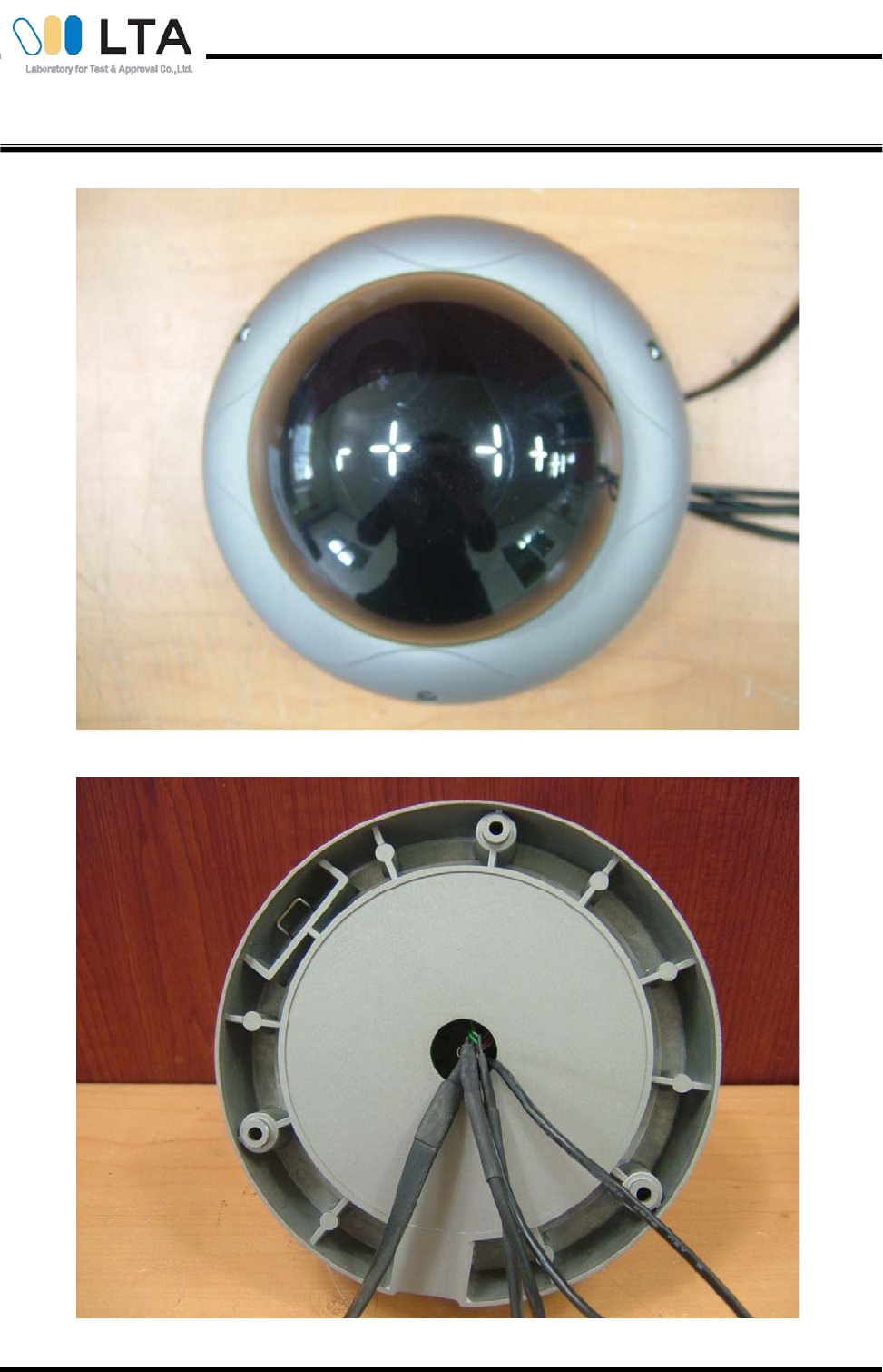
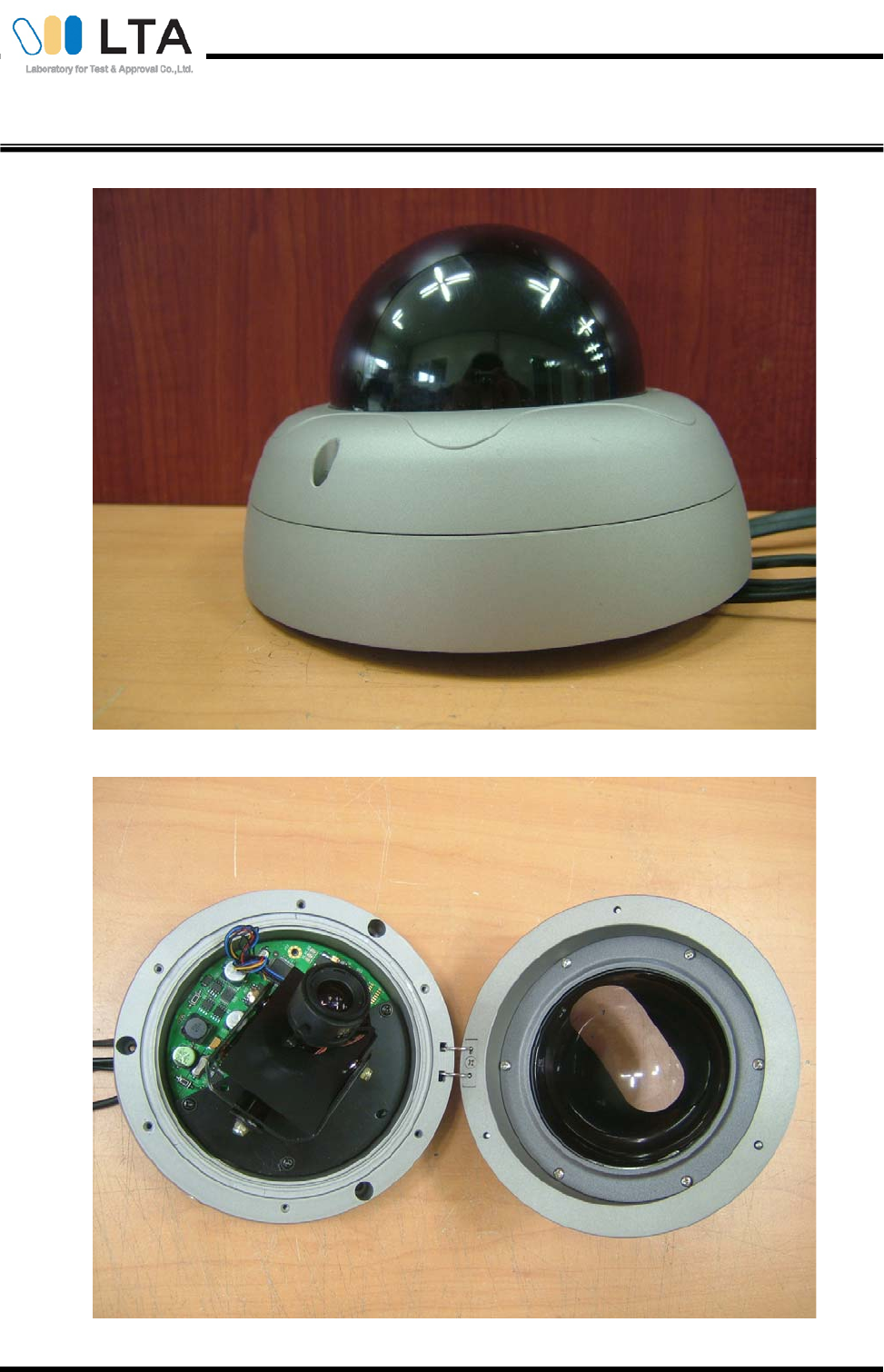
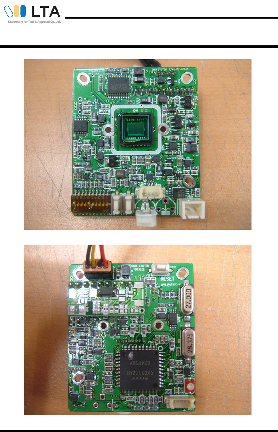
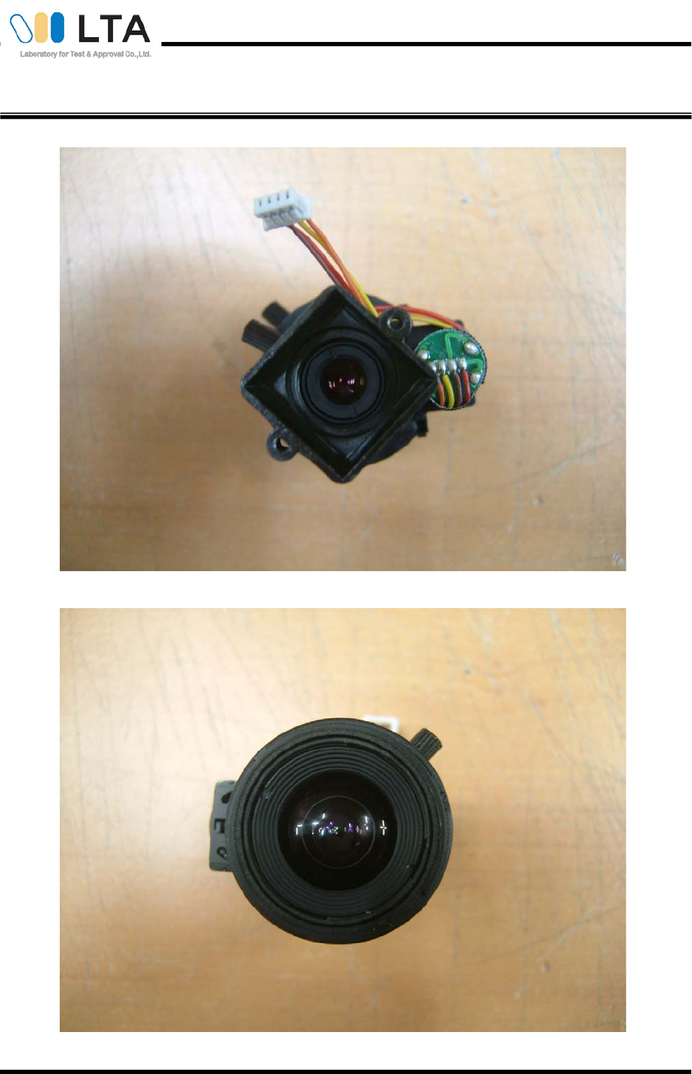
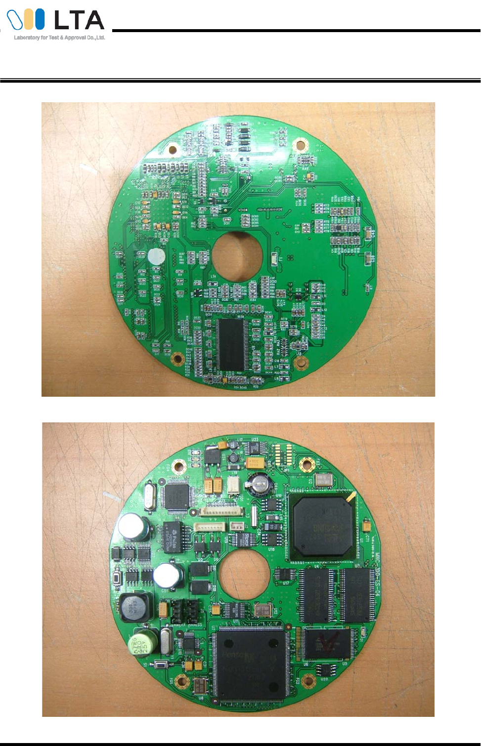
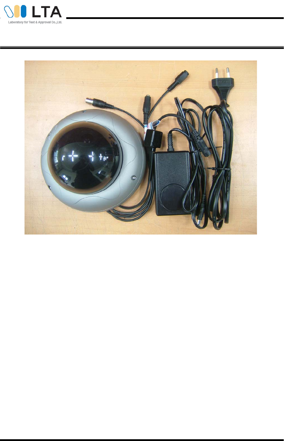
Photograph of the Equipment Under Test
Certification No. : LR500110806C
Copyright © 2008, LTA CO., LTD. Page 21 of 26
Photograph of the Equipment Under Test
Certification No. : LR500110806C
Copyright © 2008, LTA CO., LTD. Page 22 of 26
Photograph of the Equipment Under Test
Certification No. : LR500110806C
Copyright © 2008, LTA CO., LTD. Page 23 of 26
Photograph of the Equipment Under Test
Certification No. : LR500110806C
Copyright © 2008, LTA CO., LTD. Page 24 of 26
Photograph of the Equipment Under Test
Certification No. : LR500110806C
Copyright © 2008, LTA CO., LTD. Page 25 of 26
Photograph of the Equipment Under Test
Certification No. : LR500110806C
Copyright © 2008, LTA CO., LTD. Page 26 of 26
Photograph of the Equipment Under Test
