MS4600 MiniSafe Safety Light Curtains Datasheet En 201507 F266I E 01
2016-05-23
: Pdf Ms4600 Datasheet En 201507 F266I-E-01 MS4600_Datasheet_en_201507_F266I-E-01 Omron
Open the PDF directly: View PDF ![]() .
.
Page Count: 7
Rev. 6.13
Safety Light Curtains
MS4600 MS4600
For full product information, visit www.sti.com. Use the SpeedSpec Code or scan the QR Code for quick access to the specific web page.
D1
D
www.sti.com/info
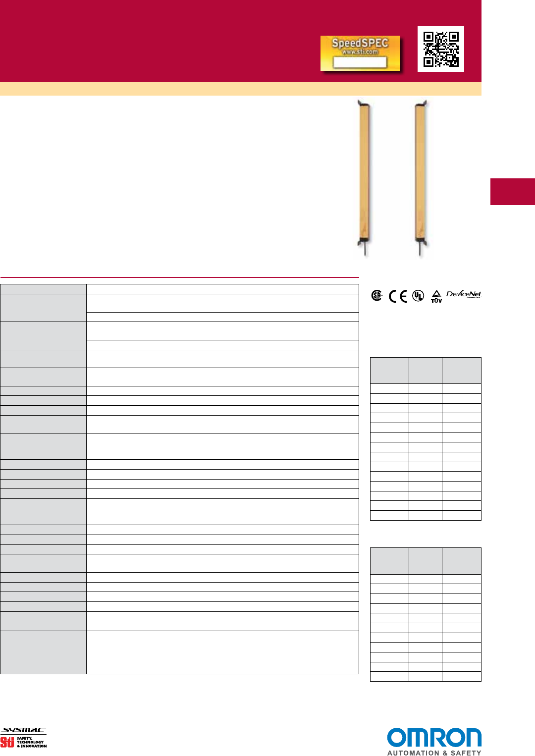
MiniSafe® Light Curtains
• Resolution:14mm(0.55in.),19mm(0.75in.)or30mm(1.18in.)resolution
• Range:7.5m(25ft.)rangeforthe14mmresolution,20m(65ft.)rangeforthe
19and30mmresolutions
• ProtectedHeights:14mmand19mmresolutionsfrom263to1393mm(10to
55in.);or30mmresolutionfrom351to2095mm(14to83in.)
• Compactsize—35x50mm(1.4x2in.)
• Nocablerequiredbetweentransmitterandreceiver
• IndividualBeamIndicators
FileNo.LR90200
R
C US
C US
Specifications for Transmitter and Receiver
Performance
ProtectedHeight: 14and19mm— 263to1393mmin86mmincrements
(10.3to54.5inchesin3.4inchincrements)
30mm— 350to2090mm(13.8to82.6in.)
OperatingRange MS46SR: 0.3to7.5m(1to25ft.)for14mmresolution
0.3to9m(1to30ft.)for19mmand30mmresolutions
MS46LR: 0.3to20m(1to65ft.)/Notavailablewith14mmresolution
Resolution: 14mm(0.55in.),19mm(0.75in.)or30mm(1.18in.).UseofExactChannelSelect
and/orFloatingBlankingmayincreasethisvalue.
ResponseTime(varies
byprotectedheight):
Seetablesatright
InputVoltage(Vin): 24VDC±20%
InputPower: 14watts(withoutloadontheoutputs)
SafetyOutputRatings: TwoPNPoutputssourcing500mAmax@Vin(seenote1).Shortcircuitprotected.
Auxiliary(Non-Safety)
OutputRatings:
OneNPNoutputsinking100mAmax@VinoronePNPoutputsourcing100mA@Vin
(seenotes1and2)
PowerSupply: 24VDC±20%.Theratingdependsonthecurrentrequirementsoftheloads
attachedtotheoutputs(seenote3).Thepowersupplymustmeettherequirements
ofIEC60204-1and61496-1.STIpartnumber42992orequivalent.
MPCEMonitoringCircuit: 50mAsteadystate@24VDC
Start/RestartInput: N.C.orN.O.momentarycontact(20mAconsumption)
EffectiveApertureAngle: ±2.5°maximum,transmitterandreceiveratoperatingrangegreaterthan3m(9.8ft.).
LightSource: GaAlAsLightEmittingDiode,850nm
Indicators Transmitter:Powerapplied(Yellow)
Receiver:MachineStop(Red),MachineRun(Green),
InterlockorAlarmIndicator(Yellow),BlankingIndicator(Amber)
Mechanical
Enclosure: Polyurethanepowder-paintedaluminum
CableLength: Optionalcablesareavailablein10,15,30and50mlengths
CableConnections
(M12):
Receiver:8-pin
Transmitter:3-pinstandard,5-pinwithMTS
Environmental
ProtectionRating: NEMA4,12;IP65
OperatingTemperature: 0to55°C(32to131°F)
RelativeHumidity: 95%maximum,non-condensing
Vibration: 5-60Hzmaximumonallthreeaxis
Shock: 10gfor0.016seconds,1,000shocksforeachaxisontwoaxis
Approvals ESPEType4(IEC61496-1/-2)
Category4/PLe(ENISO13849-1)
SIL3/SIL3CL3(IEC61508/EN62061)
UL508,UL1998,CAN/CSA-C22.2No.14,CAN/CSA-C22.2No.0.8,
CAN/CSA-C22.2No0,CAN/CSA-C22.2No205
Specicationsaresubjecttochangewithoutnotice.
Note1:VoltageavailableattheoutputsisequaltoVin-2.0VDC.
Note2:Totalcurrentrequiredbythetwosolid-stateoutputsandtheaux.outputshouldnotexceed1.1A.
Note3:Totalsystemcurrentrequirementisthesumofthetransmitter285mAandreceiver1.4Amax.(Receiver
300mA+OSSD1load+OSSD2load+Aux.outputload)
Response Times for Systems
with 14 mm and 20 mm
Resolutions
Protected
Height
(mm/in.)
No. of
Beams
Response
Time
(seconds)
263/10.4 24 <0.016
350/13.8 32 <0.017
437/17.2 40 <0.019
524/20.6 48 <0.021
611/24.1 56 <0.023
698/27.5 64 <0.025
785/30.9 72 <0.027
872/34.3 80 <0.031
959/37.7 88 <0.033
1046/41.2 96 <0.035
1133/44.6 104 <0.035
1220/48.0 112 <0.037
1306/51.4 120 <0.039
1393/54.9 128 <0.040
Response Times for Systems
with 30 mm Resolutions
Protected
Height
(mm/in.)
No. of
Beams
Response
Time
(seconds)
350/13.8 16 <0.014
524/20.6 24 <0.016
698/27.5 32 <0.017
872/34.3 40 <0.019
1046/41.2 48 <0.021
1220/48.0 56 <0.023
1393/54.9 64 <0.025
1570/61.8 72 <0.027
1741/68.6 80 <0.029
1915/75.4 88 <0.031
2090/82.3 96 <0.033
D2
D
www.sti.com/info
MS4600 Safety Light Curtains
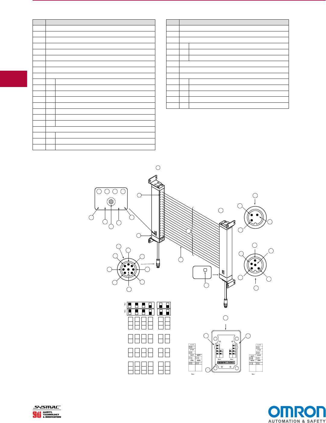
Wiring
ID Components & Indicators
1Receiver
2 IndividualBeamIndicators(oneforeachbeam)—Red
3RemovableEndCap,Accesstocongurationswitches
4 ProgramButton(mustremovesecurityscrew)
5 ChannelSelectorFloatingBlankingIndicator—Amber
6InterlockorAlarmIndicator—Yellow
7 MachineStopIndicator—Red
8 MachineRunIndicator—Green
6ReceiverConnections
I Start—GreyWire
JOSSD2—YellowWire
C OSSD1—GreenorOrangeWire
D0VDC—BrownWire
E Drain—UninsulatedWire
F+24VDC—WhiteWire
GAuxiliaryOut—BlueorVioletWire
H MPCE—PinkWire
10 InsideReceiverEndCap
A SwitchA
B SwitchB
KConnector
System Configuration
12
RECEIVER
1
2
TRANSMITTER
INDICATOR SIDE
11
14
I
9
J
N
C
G
F
E
M
D
H
L
4600 System
4600 System
3
Status
K
67
4
8
5
10
13
16
O
56
4321
ON ON
65
4321
INSIDE RCVR
ENDCAP
B
A
P
Program
Stop
Run
Interlock
FB or CS
15
MN
L
Non-MTS Transmitter
MTS Transmitter
1 2
5 6
3 4
1 2 3 4
6
5
Automatic Start
Start Interlock
Start/Restart Interlock
MPCE Inactive
MPCE Active
Exact Channel Select Inactive
Exact Channel Select Active
Floating Blanking Inactive
1 Channel Floating Blanking Active
2 Channel Floating Blacking Active
*Shown in Factory Default Settings
On On
On
Off
On
On
On
On
*
*
*
*
Off
Off
Off
Off
Off
Off
Off
Off
Receiver DIP Switch Settings
On
On
OP Mode
OP Mode
MPCE
CH Select
FB1
FB2
OP Mode
OP Mode
MPCE
CH Select
FB1
FB2
ON ON
SWA
SWB
1234 56
Switch B
Switch A
ID Components & Indicators
11 Transmitter
12 StatusIndicator—Yellow
13 TransmitterConnections(withoutMachineTestSignal)
L Drain—UninsulatedWire
M+24VDC—WhiteWire
N 0VDC—BrownWire
14 SynchronizationBeam
15 DetectionZone
16 TransmitterConnections(withMachineTestSignal)
L Drain—UninsulatedWire
M+24VDC—WhiteWire
N 0VDC—BrownWire
OMTS—BlueWire
P MTSReturn—BlackWire
D3
D
www.sti.com/info
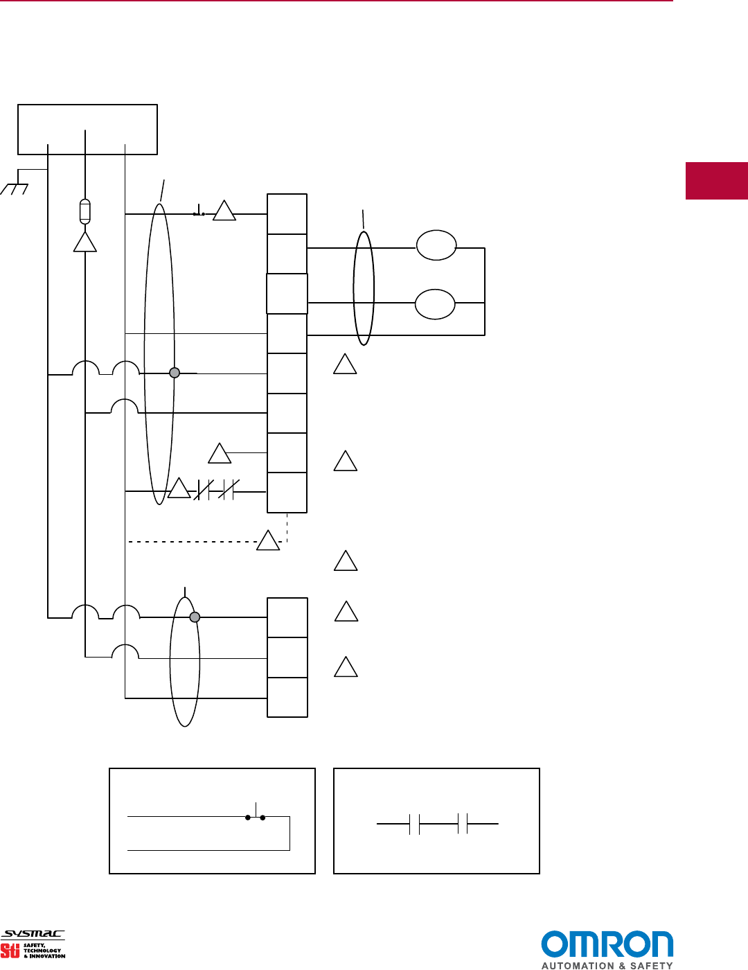
Wiring (continued)
1
EDM (External Device Monitoring) must be used
when force-guided control relays are used as the
Final Switching Devices. Connect the the Pink
wire though N/C contacts to 0 VDC.
For the purpose of bench testing prior to installation,
the user may select EDM OFF (default factory
setting). In this case the EDM line (pink wire) must
be connected to the system 0 VDC line.
Auxilary Output connect to PLC (optional)
User-supplied fuse 50 VA
If remote start is not used, connect the start line
(gray wire) to 0 VDC.
2
3
4
5
Start
OSSD 1
OSSD 2
0VDC
Shield
+24VDC
Aux.
Output
MPCE
Mon.
+24VDC
0 VDC
GRAY
DRAIN
BROWN
WHITE
4600 Receiver
Shield
4600 Transmitter
+24VDC
0VDC
DRAIN
WHITE
BROWN
START
PINK
Earth
Ground
ED2
Power Supply
2
3
4
5
ED1
ED2
ED1
Shielded Cable
Shielded Cable
Shielded Cable
1
For transmitter with MTS option
Blue
Black
ORANGE
OR
GREEN
YELLOW
VIOLET
OR
BLUE
To Machine Control Contacts
ED1 ED2
Using Solid-state Outputs
Connecting Via Two Force-Guided Relays
FGRseriesrelaysprovideforce-guidedoutputsformachinecontrol.
MS4600 Safety Light Curtains
D4
D
www.sti.com/info
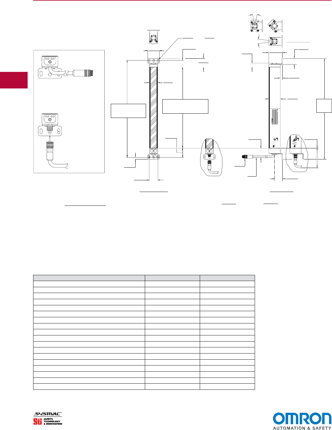
EXTENSION & CONNECTOR
WITH IN-LINE CABLE
"Q1" VERSION: ENDCAP
CONNECTOR
QUICK-DISCONNECT
"Q2" VERSION:
ENDCAP WITH
(DETECTION ZONE)
10.1
0.40
"Q2" VERSION
"Q2" VERSION
4
65.0
2.56
B = A +
16°
16°TOP VIEW
84.7
3.34
(CENTER-TO-CENTER)
"B"
Series
ini
afe
4600
ROTATION
MTG
BRKT
37.4
1.47
52.8
2.08
LG
35.0
1.38
50.0
1.97
O.D. 14.2
.58
FRONT VIEW SIDE VIEW
DIA
6.75
.265
X
11.4
.45
SLOTS (6)
40.4
1.59
34.3
1.35 C
L
L
C
DIA. 7.0
.28
9.3
.37
25.4
1.00
59.1
2.33
"C"
17.2
.68
37.8
1.49
"A"
27.2
1.07
38.1
1.50
A = DETECTION ZONE C = A + 85.4
3.36
INCHES (+\-.01)
mm (+\-.3)
DIMENSIONS:
Dimensions (mm/in.)
MS4600 Safety Light Curtains
How to Calculate Your System Dimensions:
DimensionA=DetectionZone(13.78in./350mmshown)
DimensionB=A+256/65.0±0.10/2.4
DimensionC=A+3.36/85.4
MS4600 Series/Model* A (mm) A (in)
MS46-X/R-260- 14/20 262.9 10.35
MS46-X/R-350- 14/20/30 350.0 13.78
MS46-X/R-435- 14/20 436.9 17.20
MS46-X/R-520- 14/20/30 523.8 20.62
MS46-X/R-610- 14/20 610.9 24.05
MS46-X/R-700- 14/20/30 697.7 27.47
MS46-X/R-785- 14/20 784.6 30.89
MS46-X/R-870- 14/20/30 871.7 34.32
MS46-X/R-955- 14/20 958.6 37.74
MS46-X/R-1045-14/20/30 1045.5 41.16
MS46-X/R-1130-14/20 1132.8 44.60
MS46-X/R-1215-14/20/30 1219.5 48.01
MS46-X/R-1305-14/20 1306.3 51.43
MS46-X/R-1390-14/20/30 1393.4 54.86
MS46-X/R-1570-14/30 1567.4 61.71
MS46-X/R-1745-14/30 1741.4 68.56
MS46-X/R-1920-14/30 1915.4 75.41
MS46-X/R-2095-14/30 2089.7 82.27
D5
D
www.sti.com/info
MS4600 Safety Light Curtains
1 Informationrequired.Representsthe
systemoperatingrange.Forapplications
wherethetransmitterandreceiverwillbe
mountedlessthan7.5m(25ft.)or9m(30
ft.)apart(dependingonresolution),please
selecttheSRversion.
Designator Description
MS46SR 0.3to7.5m(1to25ft.)
for14mmresolutions
0.3to9m(1to30ft.)
for20and30mmresolutions
MS46LR 0.3to20m(1to65ft.)
for20and30mmresolutions
(Notavailablefor14mm)
2 Informationrequired.Representsthe
minimumobjectresolutionofthesystem.
Designator Minimum Object Resolution
14 14mm(0.55in.)
20 19mm(0.75in.)
30 30mm(1.18in.)
3 Informationrequired.Representsthe
coverageheightofthedetectionzone.
Designator Description
260* 263mm(10.4in.)
350 351mm(13.8in.)
435* 437mm(17.2in.)
520 524mm(20.6in.)
610* 611mm(24.1in.)
700 698mm(27.5in.)
785* 785mm(30.9in.)
870 872mm(34.3in.)
955* 959mm(37.7in.)
1045 1046mm(41.2in.)
1130* 1133mm(44.6in.)
1215 1220mm(48.0in.)
1305* 1306mm(51.4in.)
1390 1393mm(54.9in.)
1570** 1567mm(61.8in.)
1745** 1741mm(68.6in.)
1920** 1915mm(75.4in.)
2095** 2090mm(82.3in.)
*Notavailablein30mmresolutions
**Onlyavailablein30mmresolutions
4 Informationrequired.Representsthe
connectortypefortransmitterandreceiver.
Designator Description
Q1 In-linecablewithquickdisconnect
(QD)connector(pigtail)
Q2 QDconnector
5 Informationrequired.Representstrans-
mitter(X)andreceiver(R)cablelength.
Cablescanbeshortenedintheeld.
Designator Description
10 10m(33ft.)
15 15m(49ft.)
30 30m(99ft.)
50 50m(164ft.)
6 Informationrequired.Representsthe
start/restartinputtype.
Designator Description
NC Normallyclosed
NO Normallyopen
7 Informationrequired.Indicatethe
Auxiliaryoutputconguration.
Designator Description
FN NPNoutputfollowsolid-state
safetyoutputs
FP PNPoutputfollowsolid-state
safetyoutputs
AN NPNoutputoperateonlyinAlarm
status
AP PNPoutputoperateonlyinAlarm
status
8 Informationoptional.Indicateoptional
MTSontransmitter.
Designator Description
M IncludeMTS
(Blank) NoMTS
9 Informationoptional.Indicateoptional
RMrelaymodule.
Designator Description
RM1 IncludeRM-1ResourceModule
RM2 IncludeRM-2ResourceModule
RM2A IncludeRM-2ACResourceModule
RM2AP IncludeRM-2AC-IPResource
Module,IP65
RM3 IncludeRM-3ResourceModule
RM4 IncludeRM-4ResourceModule
RMX IncludeRM-XResourceModule
(Blank) DonotincludeResourceModule
ToorderaMiniSafeMS4600system,simplyllintheseelds.
___-____-____-___-____X-____R-____-____-____-____
1 2 3 4 5 5 6 7 8 9
Ordering
Safety Standards and
Precautions
AllmodelsoftheMiniSafeMS4600meet
ANSI/RIAR15.06-1999(R2009)andANSI
B11.19-2010.Whenusedwithmechanical
powerpresses,OSHAindustrialsafety
standardsapplyasstatedin1910.217(c).
Forotherapplications,themachine
guardingrequirementsfoundinsection
1910.212apply.TheMiniSafeMS4600
seriesmeetsANSIcontrolreliabilityre-
quirementsforpoint-of-operationpresence
sensingdevices.
MS4600systemshavebeenECtype
examinedtotherequirementsofIEC
61496-1,-2foraType4ESPE.
TheMiniSafeMS4600shouldonlybe
usedonmachinerythatcanconsistently
andimmediatelystopanywhereinitscycle
orstroke.NeveruseaMiniSafeMS4600
onafullrevolutionclutchedpowerpress
ormachine.Ifthelightcurtaindoesnot
protectallaccesstothepointofoperation,
theunprotectedaccessmustbeguarded
byotherappropriatedevicessuchas
mechanicalguards.
Thepurchaser,installerandemployer
havetheresponsibilitytomeetalllocal,
stateandfederalgovernmentlaws,rules,
codesorregulationsrelatingtotheproper
use,installation,operationandmainte-
nanceofthiscontrolandtheguarded
machine.SeetheInstallationandOpera-
tionManualforadditionalinformation.
Allapplicationexamplesdescribedare
forillustrationpurposesonly.Actualinstal-
lationswilldifferfromthoseindicated.
D6
D
www.sti.com/info
For information on safety light
curtain accessories, see www.sti.com
For information on Resource
Modules, see www.sti.com
✎
✎
MS4600 Safety Light Curtains
Ordering (continued)
Spare Parts and Accessories
Transmitter Cables
CBL-46TX-10M TransmitterCable,10meter(32.8ft.)
CBL-46TX-15M TransmitterCable,15meter(49.2ft.)
CBL-46TX-30M TransmitterCable,30meter(98.5ft.)
MTS Version Transmitter Cables
CBL-46TXM-10M TransmitterCable,10m(32.8ft.)
CBL-46TXM-15M TransmitterCable15m(49.2ft.)
CBL-46TXM-30M TransmitterCable,30m(98.5ft.)
Receiver Cables
CBL-46RX-10M ReceiverCable,10meter(32.8ft.)
CBL-46RX-15M ReceiverCable,15meter(49.2ft.)
CBL-46RX-30M ReceiverCable,30meter(98.5ft.)
Standard (Non-MTS) Transmitter
CBL-46TXT-1M Double-ended,QuickDisconnect,1meter(3.28
ft),Transmitter
CBL-46TXT-5M Double-ended,QuickDisconnect,5meter(16.4
ft),Transmitter
CBL-46TXT-10M Double-ended,QuickDisconnect,10meter(32.8
ft),Transmitter
CBL-46TXT-15M Double-ended,QuickDisconnect,15meter(49.2
ft),Transmitter
CBL-46TXT-25M Double-ended,QuickDisconnect,25meter(82.0
ft),Transmitter
CBL-46TXT-30M Double-ended,QuickDisconnect,30meter(98.4
ft),Transmitter
MTS Double-ended Version Transmitter Cables
CBL-46TXTM-1M MTSVersionDouble-ended,QuickDisconnect,1
meter(3.28ft),Transmitter
CBL-46TXTM-5M MTSVersionDouble-ended,QuickDisconnect,5
meter(16.4ft),Transmitter
CBL-46TXTM-10M MTSVersionDouble-ended,QuickDisconnect,
10meter(32.8ft),Transmitter
CBL-46TXTM-15M MTSVersionDouble-ended,QuickDisconnect,
15meter(49.2ft),Transmitter
CBL-46TXTM-25M MTSVersionDouble-ended,QuickDisconnect,
25meter(82.0ft),Transmitter
CBL-46TXTM-30M MTSVersionDouble-ended,QuickDisconnect,
30meter(98.4ft),Transmitter
Double-ended Receiver Cable
CBL-46RXT-1M Double-ended,QuickDisconnect,1meter(3.28
ft),Receiver
CBL-46RXT-5M Double-ended,QuickDisconnect,5meter(16.4
ft),Receiver
CBL-46RXT-10M Double-ended,QuickDisconnect,10meter(32.8
ft),Receiver
CBL-46RXT-15M Double-ended,QuickDisconnect,15meter(49.2
ft),Receiver
CBL-46RXT-25M Double-ended,QuickDisconnect,25meter(82.0
ft),Receiver
CBL-46RXT-30M Double-ended,QuickDisconnect,30meter(98.4
ft),Receiver
Bulkhead Connectors
PMC-46RX ReceiverBulkheadConnector,36in.(914.4mm)
Leads
PMC-46TX TransmitterBulkheadConnector,36in.(914.4
mm)Leads
PMC-46TXM MTSVersionBulkheadConnector,36in.(914.4
mm)Leads
Resource Modules
RM-1 RM-1ResourceModule
RM-2 RM-2ResourceModule
RM-2AC RM-2ACResourceModule/PowerSupply
RM-2AC-IP RM-2ACResourceModule/PowerSupply,IP65
MetalEnclosure
RM-3 RM-3MuteModule
RM-X RM-XSafetyRelay,22.5mmDINenclosure

OMRON CANADA, INC. • HEAD OFFICE
Toronto, ON, Canada • 416.286.6465 • 866.986.6766 • www.omron247.com
OMRON ELECTRONICS DE MEXICO • HEAD OFFICE
México DF • 52.
55.59.01.43.00
• 01-800-226-6766 • mela@omron.com
OMRON ELECTRONICS DE MEXICO • SALES OFFICE
Apodaca, N.L. • 52.81.11.56.99.20 • 01-800-226-6766 • mela@omron.com
OMRON ELETRÔNICA DO BRASIL LTDA • HEAD OFFICE
São Paulo, SP, Brasil • 55.11.2101.6300 • www.omron.com.br
OMRON ARGENTINA • SALES OFFICE
Cono Sur • 54.11.4783.5300
OMRON CHILE • SALES OFFICE
Santiago • 56.9.9917.3920
OTHER OMRON LATIN AMERICA SALES
54.11.4783.5300
Authorized Distributor:
F266I-E-01 07/15
Note: Specifications are subject to change. © 2015 Omron Electronics LLC Printed in U.S.A.
Printed on recycled paper.
Automation Control Systems
• Machine Automation Controllers (MAC) • Programmable Controllers (PLC)
• Operator interfaces (HMI) • Distributed I/O • Software
Drives & Motion Controls
• Servo & AC Drives • Motion Controllers & Encoders
Temperature & Process Controllers
• Single and Multi-loop Controllers
Sensors & Vision
• Proximity Sensors • Photoelectric Sensors • Fiber-Optic Sensors
• Amplified Photomicrosensors • Measurement Sensors
• Ultrasonic Sensors • Vision Sensors
Industrial Components
• RFID/Code Readers • Relays • Pushbuttons & Indicators
• Limit and Basic Switches • Timers • Counters • Metering Devices
• Power Supplies
Safety
• Laser Scanners • Safety Mats • Edges and Bumpers • Programmable Safety
Controllers • Light Curtains • Safety Relays • Safety Interlock Switches
OMRON AUTOMATION AND SAFETY • THE AMERICAS HEADQUARTERS • Chicago, IL USA • 847.843.7900 • 800.556.6766 • www.omron247.com
OMRON EUROPE B.V. •
Wegalaan 67-69, NL-2132 JD, Hoofddorp, The Netherlands.
•
+31 (0) 23 568 13 00
•
www.industrial.omron.eu
