NOS_2_Analysis_Handbook_Ref_60459300M_Dec88_Part_2 NOS 2 Analysis Handbook Ref 60459300M Dec88 Part
NOS_2_Analysis_Handbook_Ref_60459300M_Dec88_Part_2 NOS_2_Analysis_Handbook_Ref_60459300M_Dec88_Part_2
User Manual: Pdf NOS_2_Analysis_Handbook_Ref_60459300M_Dec88_Part_2
Open the PDF directly: View PDF ![]() .
.
Page Count: 232 [warning: Documents this large are best viewed by clicking the View PDF Link!]
*PROC Directive
0ms
0$ms
Parameter Description
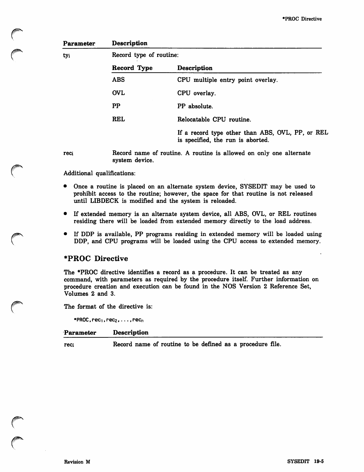
tyi Record type of routine:
Record Type Description
ABS CPU multiple entry point overlay.
OVL CPU overlay.
PP PP absolute.
REL Relocatable CPU routine.
If a record type other than ABS, OVL, PP, or REL
is specified, the run is aborted.
reci Record name of routine. A routine is allowed on only one alternate
system device.
Additional qualifications:
• Once a routine is placed on an alternate system device, SYSEDIT may be used to
prohibit access to the routine; however, the space for that routine is not released
until LIBDECK is modified and the system is reloaded.
• If extended memory is an alternate system device, all ABS, OVL, or REL routines
residing there will be loaded from extended memory directly to the load address.
• If DDP is available, PP programs residing in extended memory will be loaded using
DDP, and CPU programs will be loaded using the CPU access to extended memory.
*PROC Directive
The *PROC directive identifies a record as a procedure. It can be treated as any
command, with parameters as required by the procedure itself. Further information on
procedure creation and execution can be found in the NOS Version 2 Reference Set,
Volumes 2 and 3.
The format of the directive is:
*PROC,reci,rec2,...,recn
Parameter Description
reci Record name of routine to be defined as a procedure file.
Revision M SYSEDIT 19-5
*SC Directive
*SC Directive
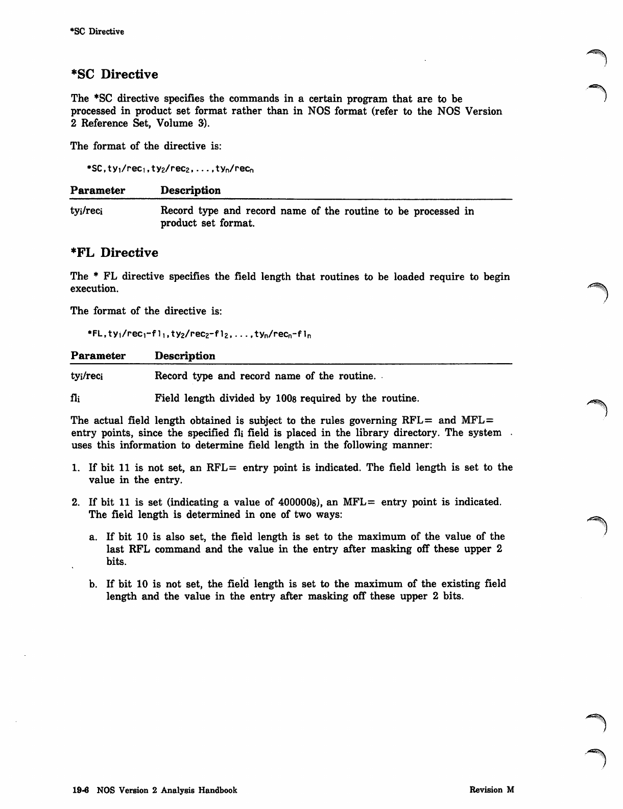
The *SC directive specifies the commands in a certain program that are to be
processed in product set format rather than in NOS format (refer to the NOS Version
2 Reference Set, Volume 3).
The format of the directive is:
*SC,tyi/reci,ty2/rec2 tyn/recn
Parameter Description
tyi/reci Record type and record name of the routine to be processed in
product set format.
*FL Directive
The * FL directive specifies the field length that routines to be loaded require to begin
execution.
The format of the directive is:
*FL,tyi/reci-f li,ty2/rec2-fl2 tyn/recn-fln
Parameter Description
tyi/reci Record type and record name of the routine.
fli Field length divided by 1008 required by the routine.
The actual field length obtained is subject to the rules governing RFL= and MFL=
entry points, since the specified fli field is placed in the library directory. The system .
uses this information to determine field length in the following manner:
1. If bit 11 is not set, an RFL= entry point is indicated. The field length is set to the
value in the entry.
2. If bit 11 is set (indicating a value of 400000s), an MFL= entry point is indicated.
The field length is determined in one of two ways:
a. If bit 10 is also set, the field length is set to the maximum of the value of the
last RFL command and the value in the entry after masking off these upper 2
bits.
b. If bit 10 is not set, the field length is set to the maximum of the existing field
length and the value in the entry after masking off these upper 2 bits.
19-6 NOS Version 2 Analysis Handbook Revision M
0$m\.
r
*/ Directive
*/ Directive
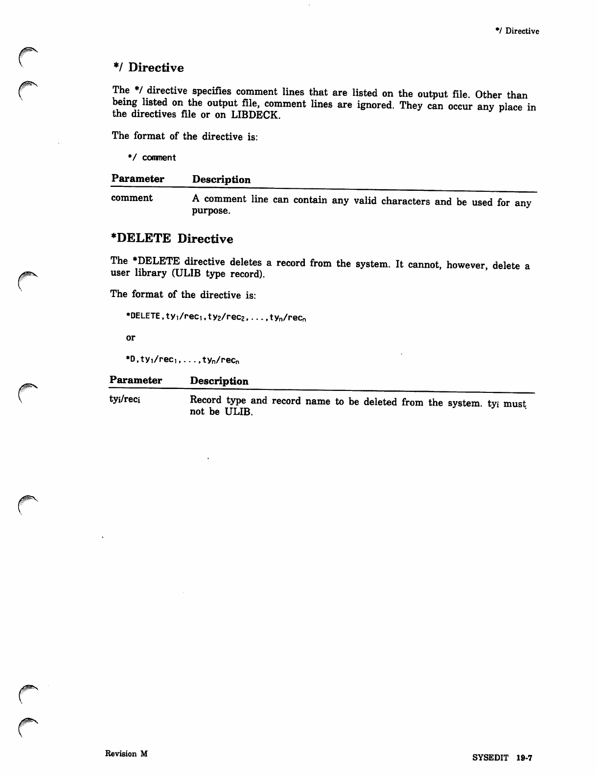
The */ directive specifies comment lines that are listed on the output file. Other than
being listed on the output file, comment lines are ignored. They can occur any place in
the directives file or on LIBDECK.
The format of the directive is:
*/ comment
Parameter Description
comment A comment line can contain any valid characters and be used for any
purpose.
♦DELETE Directive
The *DELETE directive deletes a record from the system. It cannot, however, delete a
user library (ULIB type record).
The format of the directive is:
•DELETE, ty1/reci,ty2/rec2 tyn/recn
or
*D,tyi/reci,...,tyn/recn
Parameter Description
tyi/reci Record type and record name to be deleted from the system, tvi must
not be ULIB.
Revision M SYSEDIT 19-7
*PILE Directive
*FILE Directive
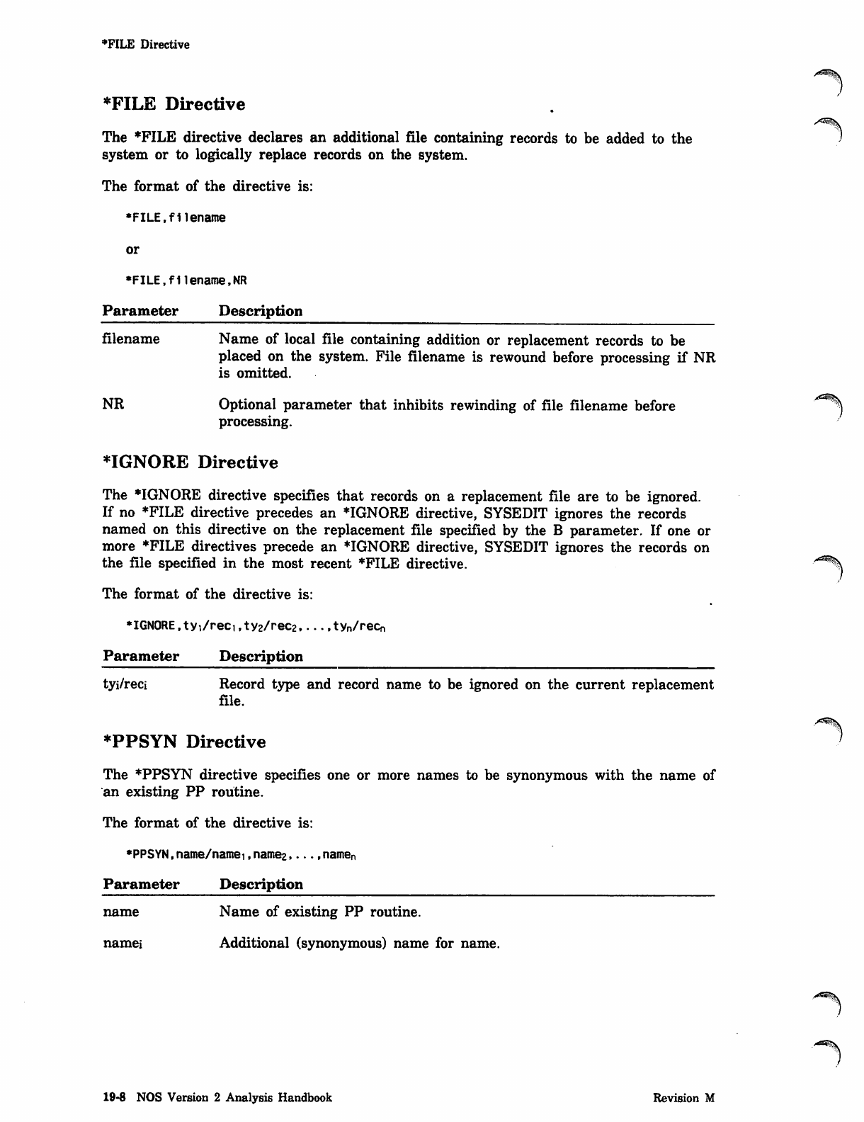
The *FILE directive declares an additional file containing records to be added to the
system or to logically replace records on the system.
The format of the directive is:
•FILE,filename
or
•FILE.fllename.NR
Parameter Description
filename Name of local file containing addition or replacement records to be
placed on the system. File filename is rewound before processing if NR
is omitted.
NR Optional parameter that inhibits rewinding of file filename before
processing.
♦IGNORE Directive
The *IGNORE directive specifies that records on a replacement file are to be ignored.
If no *FILE directive precedes an *IGNORE directive, SYSEDIT ignores the records
named on this directive on the replacement file specified by the B parameter. If one or
more *FILE directives precede an *IGNORE directive, SYSEDIT ignores the records on
the file specified in the most recent *FILE directive.
The format of the directive is:
•IGNORE,tyi/reci,ty2/rec2,.. .,tyn/recn
Parameter Description
tyi/reci Record type and record name to be ignored on the current replacement
file.
*PPSYN Directive
The *PPSYN directive specifies one or more names to be synonymous with the name of
an existing PP routine.
The format of the directive is:
•PPSYN.name/namei ,name2,... ,namen
Parameter Description
name Name of existing PP routine.
namei Additional (synonymous) name for name.
~>
■'*s*%
19-8 NOS Version 2 Analysis Handbook Revision M
Record Types
Record Types
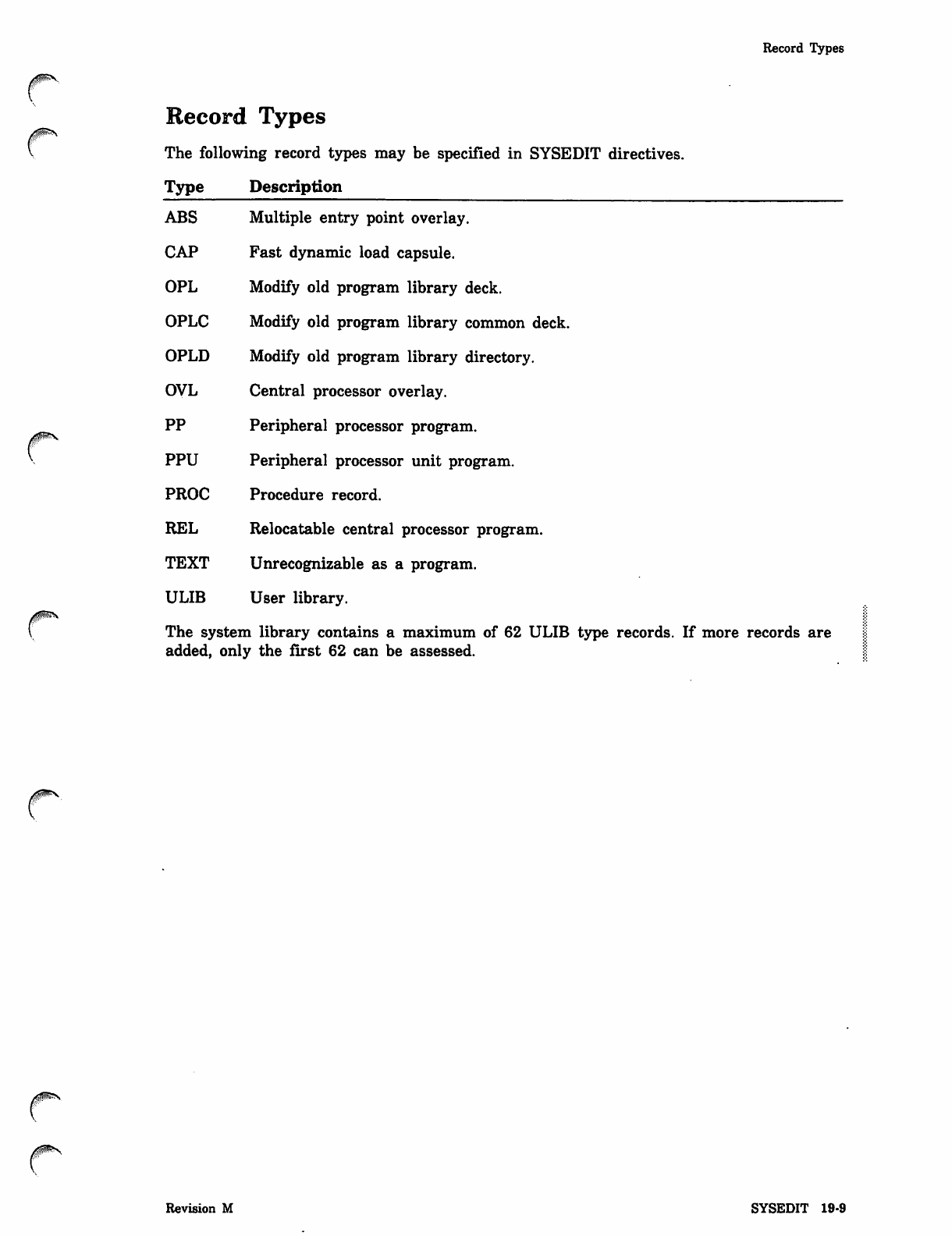
The following record types may be specified in SYSEDIT directives.
Type Description
ABS Multiple entry point overlay.
CAP Fast dynamic load capsule.
OPL Modify old program library deck.
OPLC Modify old program library common deck.
OPLD Modify old program library directory.
OVL Central processor overlay.
PP Peripheral processor program.
PPU Peripheral processor unit program.
PROC Procedure record.
REL Relocatable central processor program.
TEXT Unrecognizable as a program.
ULIB U s e r lib r a r y.
The system library contains a maximum of 62 ULIB type records. If more records are
added, only the first 62 can be assessed.
Revision M SYSEDIT 19-9

^ System File Initialization 20
f * : —
ISF 20-1
Deadstart Sequencing 20-4
#^
^

v_-
System File Initialization 20
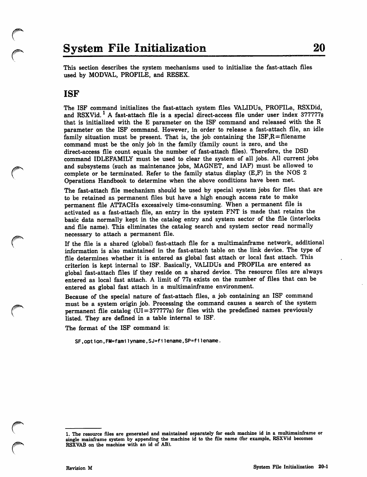
This section describes the system mechanisms used to initialize the fast-attach files
used by MODVAL, PROFILE, and RESEX.
ISF
The ISF command initializes the fast-attach system files VALIDUs, PROFILa, RSXDid,
and RSXVid.1 A fast-attach file is a special direct-access file under user index 377777s
that is initialized with the E parameter on the ISF command and released with the R
parameter on the ISF command. However, in order to release a fast-attach file, an idle
family situation must be present. That is, the job containing the ISF,R=filename
command must be the only job in the family (family count is zero, and the
direct-access file count equals the number of fast-attach files). Therefore, the DSD
command IDLEFAMILY must be used to clear the system of all jobs. All current jobs
and subsystems (such as maintenance jobs, MAGNET, and IAF) must be allowed to
complete or be terminated. Refer to the family status display (E,F) in the NOS 2
Operations Handbook to determine when the above conditions have been met.
The fast-attach file mechanism should be used by special system jobs for files that are
to be retained as permanent files but have a high enough access rate to make
permanent file ATTACHs excessively time-consuming. When a permanent file is
activated as a fast-attach file, an entry in the system FNT is made that retains the
basic data normally kept in the catalog entry and system sector of the file (interlocks
and file name). This eliminates the catalog search and system sector read normally
necessary to attach a permanent file.
If the file is a shared (global) fast-attach file for a multimainframe network, additional
information is also maintained in the fast-attach table on the link device. The type of
file determines whether it is entered as global fast attach or local fast attach. This
criterion is kept internal to ISF. Basically, VALIDUs and PROFILa are entered as
global fast-attach files if they reside on a shared device. The resource files are always
entered as local fast attach. A limit of 77s exists on the number of files that can be
entered as global fast attach in a multimainframe environment.
Because of the special nature of fast-attach files, a job containing an ISF command
must be a system origin job. Processing the command causes a search of the system
permanent file catalog (UI = 377777s) for files with the predefined names previously
listed. They are defined in a table internal to ISF.
The format of the ISF command is:
SF,opt 1on,FM=fami 1yname,SJ=fllename,SP=fllename.
1. The resource files are generated and maintained separately for each machine id in a multimainframe or
single mainframe system by appending the machine id to the file name (for example, RSXVid becomes
RSXVAB on the machine with an id of AB).
Revision M System File Initialization 20-1
ISF
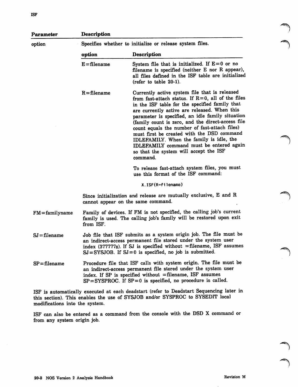
Parameter Description
option Specifies whether to initialize or release system files.
option Description
E=filename System file that is initialized. If E=0 or no
filename is specified (neither E nor R appear),
all files defined in the ISF table are initialized
(refer to table 20-1).
R=filename Currently active system file that is released
from fast-attach status. If R=0, all of the files
in the ISF table for the specified family that
are currently active are released. When this
parameter is specified, an idle family situation
(family count is zero, and the direct-access file
count equals the number of fast-attach files)
must first be created with the DSD command
IDLEFAMILY. When the family is idle, the
IDLEFAMILY command must be entered again
so that the system will accept the ISF
command.
To release fast-attach system files, you must
use this format of the ISF command:
X.ISF(R=f1lename)
Since initialization and release are mutually exclusive, E and R
cannot appear on the same command.
Family of devices. If FM is not specified, the calling job's current
family is used. The calling job's family will be restored upon exit
from ISF.
Job file that ISF submits as a system origin job. The file must be
an indirect-access permanent file stored under the system user
index (377777s). If SJ is specified without = filename, ISF assumes
SJ = SYSJOB. If SJ=0 is specified, no job is submitted.
Procedure file that ISF calls with system origin. The file must be
an indirect-access permanent file stored under the system user
index. If SP is specified without = filename, ISF assumes
SP=SYSPROC. If SP=0 is specified, no procedure is called.
ISF is automatically executed at each deadstart (refer to Deadstart Sequencing later in
this section). This enables the use of SYSJOB and/or SYSPROC to SYSEDIT local
modifications into the system.
ISF can also be entered as a command from the console with the DSD X command or
from any system origin job.
FM=familyname
SJ=filename
SP=filename
20-2 NOS Version 2 Analysis Handbook Revision M
ISF
0$ms.
r
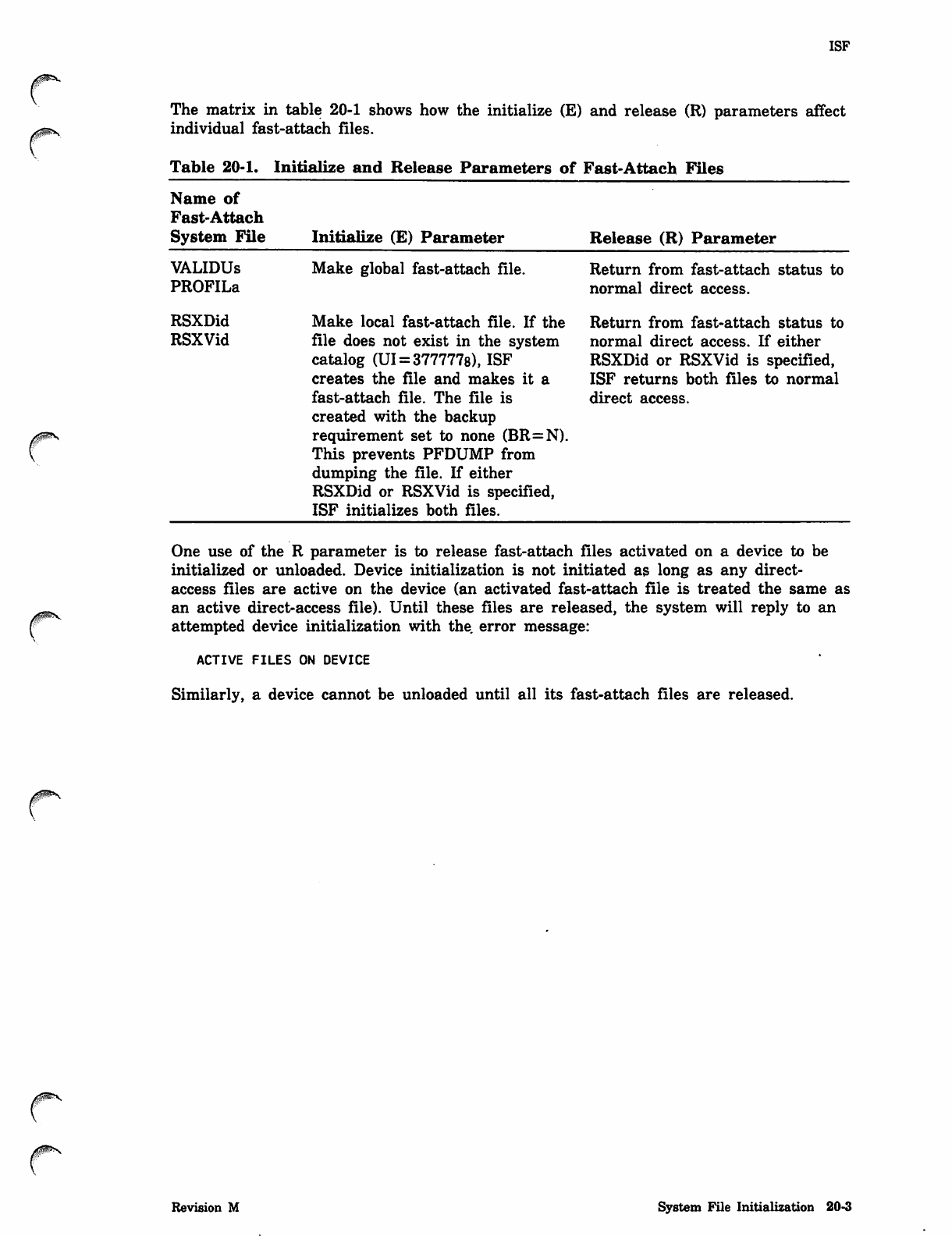
The matrix in table 20-1 shows how the initialize (E) and release (R) parameters affect
individual fast-attach files.
Table 20-1. Initialize and Release Parameters of Fast-Attach Files
Name of
Fast-Attach
System File Initialize (E) Parameter Release (R) Parameter
VALIDUs
PROFILa
RSXDid
RSXVid
Make global fast-attach file.
Make local fast-attach file. If the
file does not exist in the system
catalog (UI = 377777s), ISF
creates the file and makes it a
fast-attach file. The file is
created with the backup
requirement set to none (BR=N).
This prevents PFDUMP from
dumping the file. If either
RSXDid or RSXVid is specified,
ISF initializes both files.
Return from fast-attach status to
normal direct access.
Return from fast-attach status to
normal direct access. If either
RSXDid or RSXVid is specified,
ISF returns both files to normal
direct access.
One use of the R parameter is to release fast-attach files activated on a device to be
initialized or unloaded. Device initialization is not initiated as long as any direct-
access files are active on the device (an activated fast-attach file is treated the same as
an active direct-access file). Until these files are released, the system will reply to an
attempted device initialization with the. error message:
ACTIVE FILES ON DEVICE
Similarly, a device cannot be unloaded until all its fast-attach files are released.
0$ms
Revision M System File Initialization 20-3
/*^%l
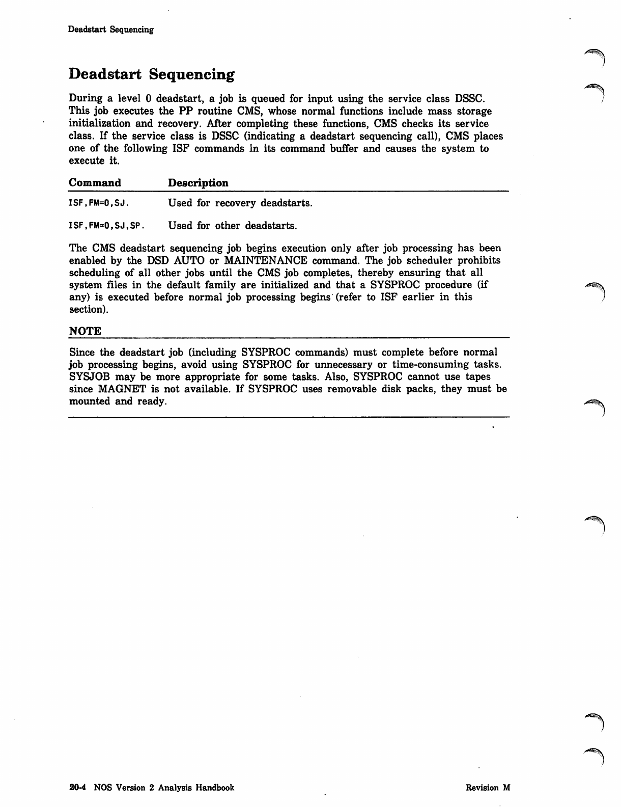
Deadstart Sequencing
Deadstart Sequencing
During a level 0 deadstart, a job is queued for input using the service class DSSC.
This job executes the PP routine CMS, whose normal functions include mass storage
initialization and recovery. After completing these functions, CMS checks its service
class. If the service class is DSSC (indicating a deadstart sequencing call), CMS places
one of the following ISF commands in its command buffer and causes the system to
execute it.
Command Description
ISF,FM=0,SJ. Used for recovery deadstarts.
ISF,FM=0,SJ,SP. Used for other deadstarts.
The CMS deadstart sequencing job begins execution only after job processing has been
enabled by the DSD AUTO or MAINTENANCE command. The job scheduler prohibits
scheduling of all other jobs until the CMS job completes, thereby ensuring that all
system files in the default family are initialized and that a SYSPROC procedure (if -m^
any) is executed before normal job processing begins (refer to ISF earlier in this
section).
NOTE
Since the deadstart job (including SYSPROC commands) must complete before normal
job processing begins, avoid using SYSPROC for unnecessary or time-consuming tasks.
SYSJOB may be more appropriate for some tasks. Also, SYSPROC cannot use tapes
since MAGNET is not available. If SYSPROC uses removable disk packs, they must be
mounted and ready.
20-4 NOS Version 2 Analysis Handbook Revision M
Tracer/Probe Utilities 21
Tracer Utility . , 21-1
TRACER Commands .', 21-4
ACPD Command 21-4
ENDCPD Command 21-5
ICPD Command 21-6
Output File Format 21-8
Summary File Format 21-19
Data Items Reported by TRACER 21-19
Fast Loop Items 21-22
Fast Loop Samples 21-22
PPs Active 21-22
Move Request Pending ....... 21-22
No PP Available 21-23
No CPP Available 21-23
EM Transfer in Progress 21-23
MTR Cycle Time 21-23
Monitor Mode — CPU0/CPU1 ., .... 21-23
Scheduler Active 21-24
Channel Reserved 21-24
Channel Active , 21-25
Channel Requested 21-26
Requests Pending .- 21-26
Buffered I/O Lists .;..... 21-26
Buffered I/O Channel Busy 21-26
CPU Usage 21-27
Subsystem CPU Usage 21-27
Medium Loop Items 251-28
Medium Loop Samples . 21-28
CPS in W Status .., 21-28
CPS in X Status 21-28
CPS in I Status , 21-28
Same Move Request 21-28
FL Available , 21-28
User EM Available 21-29
Noninteractive Jobs 21-29
Detached Jobs 21-29
Online Jobs .............. 21-29
Preinitial Job Step 21-29
Executing 21-29
Scheduler Rollout 21-29
SCP Rollin 21-29
SCP Rollout 21-29
Timed/Event Rollout 21-30
Interactive Rollout 21-30
Disabled Rollout 21-30
Suspended Rollout 21-30
Rollout File Error 21-30
EJT Entries in Use 21-30
FL at Control Points 21-30
FL at Pseudo-control Points 21-31
FL in Rollout Queue 21-31
EM Memory at Control Points 21-31
EM Memory at Pseudo-control Points ... 21-31
EM in Rollout Queue ... 21-31
Subsystem FL , ..... .. 21-31
Slow Loop Items ... .... 21-32 '^\
Slow Loop Samples ...21-32
IAF Users . ....... 21-32
IAF Pots Allocated ... .■ ...... 21-32
IAF Pots in Use ........... 21-32
Queue Files Assigned , .... 21-32
Input Files ;. 21-32
Print Files ... 21-32
Punch Files 21-32
Other Queue Files ... 21-32
QFT Entries in Use 21-33
Tape Drives in Use ... , 21-33
Tracks Available 21-33
CPPs Active 21-33
ISHARED Table Changes 21-33
ISHARED Device Updates 21-33
ISHARED Seek Time 21-33
ISHARED Updating Time 21-33
Statistical Summary -..*....,. '. 21-34
MTR Maximum Time 21-34
Direct Moves . 21-34
Worst Case MTR Cycle Time 21-34
Missed Clock Updates .,. 21-34
Extended Memory Moves .... 21-34
Central Memory Moves 21-34
Total Rollouts ...:... 21-34
Secondary Rollouts 21-34
Total Sectors Rolled ,,.... .,.. :, 21-34
Secondary Sec Rolled .— ..... 21-35
Rollouts/User Limits 21-35
Time Slices : 21-35
PP Priority Exchanges 21-35
No Comm Buffer Avail 21-35
No PCP Available ................-. .., ". 21-35
EJT Scans , 21-35
Schedulable Jobs 21-35
Jobs Preempted ...- 21-35
Jobs Scheduled 21-35
Scheduled No Constraints ....... ..... .......... 21-36
Insufficient CM Scans 21-36
Insufficient EM Scans 21-36
No Control Point Scans -,-. ... 21-36
PROBE Utility 21-37
Tracer/Probe Utilities
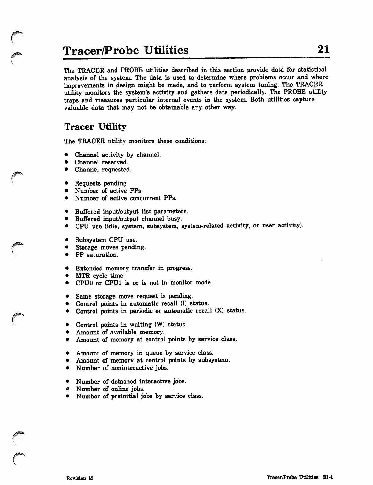
The TRACER and PROBE utilities described in this section provide data for statistical
analysis of the system. The data is used to determine where problems occur and where
improvements in design might be made, and to perform system tuning. The TRACER
utility monitors the system's activity and gathers data periodically. The PROBE utility
traps and measures particular internal events in the system. Both utilities capture
valuable data that may not be obtainable any other way.
r
Tracer Utility
The TRACER utility monitors these conditions:
Channel activity by channel.
Channel reserved.
Channel requested.
Requests pending.
Number of active PPs.
Number of active concurrent PPs.
Buffered input/output list parameters.
Buffered input/output channel busy.
CPU use (idle, system, subsystem, system-related activity, or user activity).
Subsystem CPU use.
Storage moves pending.
PP saturation.
Extended memory transfer in progress.
MTR cycle time.
CPUO or CPU1 is or is not in monitor mode.
Same storage move request is pending.
Control points in automatic recall (I) status.
Control points in periodic or automatic recall (X) status.
Control points in waiting (W) status.
Amount of available memory.
Amount of memory at control points by service class.
Amount of memory in queue by service class.
Amount of memory at control points by subsystem.
Number of noninteractive jobs.
Number of detached interactive jobs.
Number of online jobs.
Number of preinitial jobs by service class.
Revision M Tracer/Probe Utilities 21-1
Tracer Utility
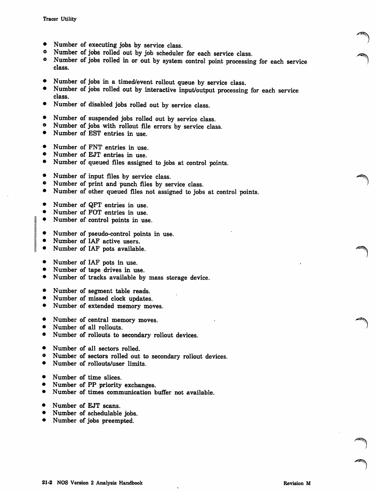
• Number of executing jobs by service class.
® N u m b e r o f j o b s r o l l e d o u t b y j o b s c h e d u l e r f o r e a c h s e r v i c e c l a s s . ^
© Number of jobs rolled in or out by system control point processing for each service 1
class.
Number of jobs in a timed/event rollout queue by service class.
Number of jobs rolled out by interactive input/output processing for each service
class.
Number of disabled jobs rolled out by service class.
Number of suspended jobs rolled out by service class.
Number of jobs with rollout file errors by service class.
Number of EST entries in use.
Number of FNT entries in use.
Number of EJT entries in use.
Number of queued files assigned to jobs at control points.
Number of input files by service class.
Number of print and punch files by service class.
Number of other queued files not assigned to jobs at control points.
Number of QFT entries in use.
Number of FOT entries in use.
Number of control points in use.
Number of pseudo-control points in use.
Number of IAF active users.
Number of IAF pots available.
Number of IAF pots in use.
Number of tape drives in use.
Number of tracks available by mass storage device.
Number of segment table reads.
Number of missed clock updates.
Number of extended memory moves.
Number of central memory moves. **%
Number of all rollouts. >
Number of rollouts to secondary rollout devices.
Number of all sectors rolled.
Number of sectors rolled out to secondary rollout devices.
Number of rollouts/user limits.
Number of time slices.
Number of PP priority exchanges.
Number of times communication buffer not available.
Number of EJT scans.
Number of schedulable jobs.
Number of jobs preempted.
21-2 NOS Version 2 Analysis Handbook Revision M
Tracer Utility
r
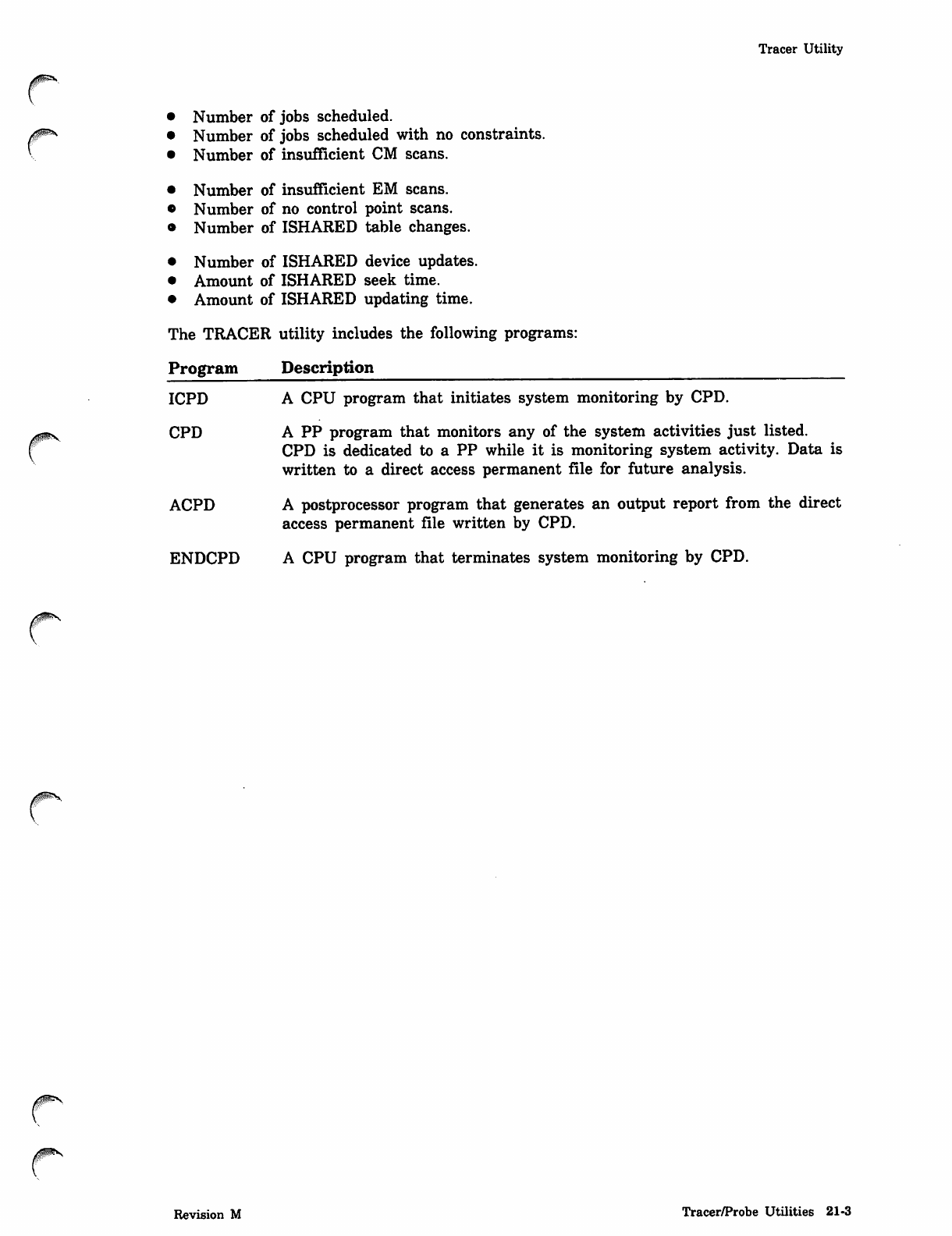
• Number of jobs scheduled.
• Number of jobs scheduled with no constraints.
• Number of insufficient CM scans.
• Number of insufficient EM scans.
• Number of no control point scans.
• Number of ISHARED table changes.
• Number of ISHARED device updates.
• Amount of ISHARED seek time.
• Amount of ISHARED updating time.
The TRACER utility includes the following programs:
Program Description
ICPD A CPU program that initiates system monitoring by CPD.
CPD A PP program that monitors any of the system activities just listed.
CPD is dedicated to a PP while it is monitoring system activity. Data is
written to a direct access permanent file for future analysis.
ACPD A postprocessor program that generates an output report from the direct
access permanent file written by CPD.
ENDCPD A CPU program that terminates system monitoring by CPD.
A0S*S,
0sms.
Revision M Tracer/Probe Utilities 21-3
TRACER Commands
TRACER Commands
TRACER commands are described next.
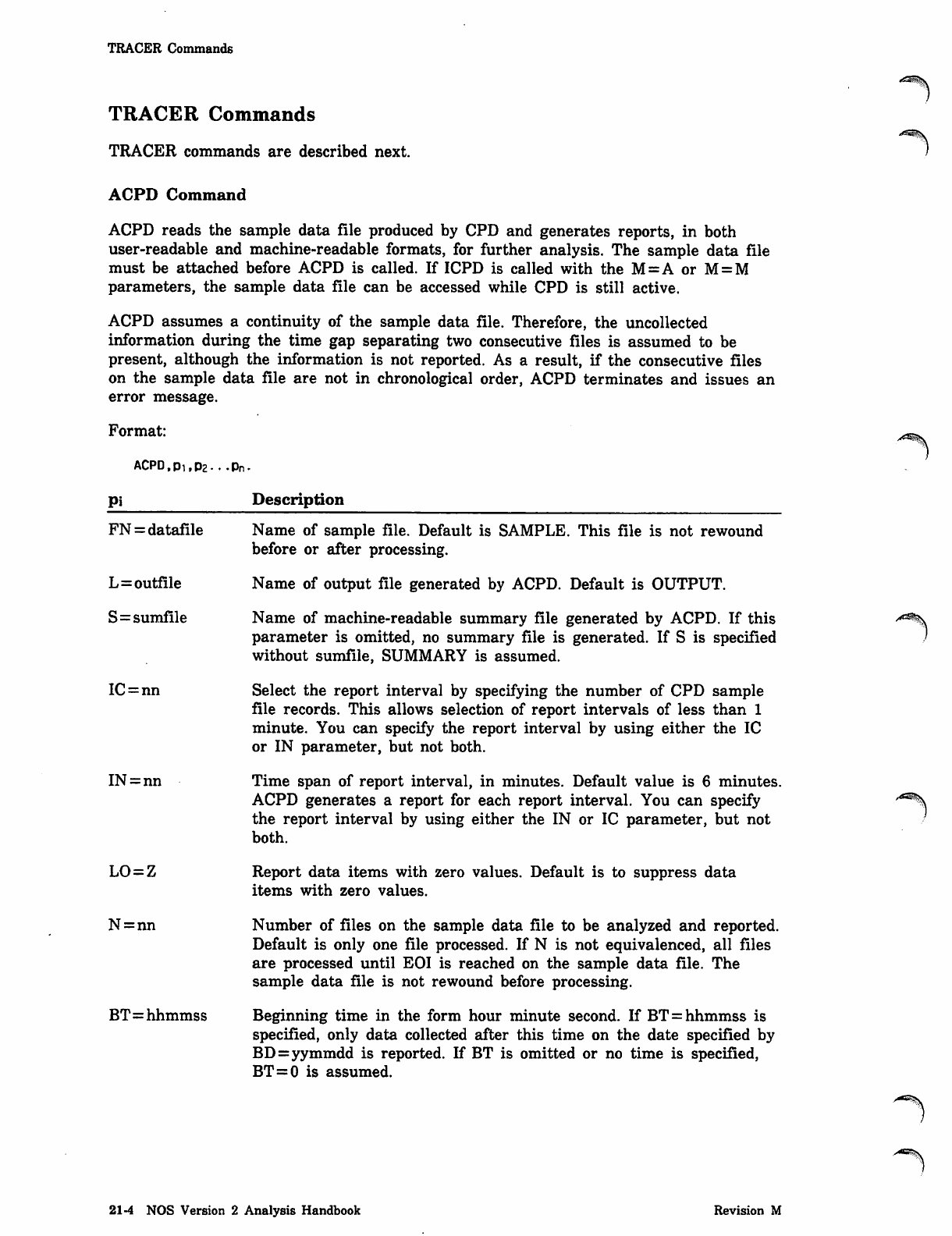
ACPD Command
ACPD reads the sample data file produced by CPD and generates reports, in both
user-readable and machine-readable formats, for further analysis. The sample data file
must be attached before ACPD is called. If ICPD is called with the M=A or M = M
parameters, the sample data file can be accessed while CPD is still active.
ACPD assumes a continuity of the sample data file. Therefore, the uncollected
information during the time gap separating two consecutive files is assumed to be
present, although the information is not reported. As a result, if the consecutive files
on the sample data file are not in chronological order, ACPD terminates and issues an
error message.
Format:
ACPD,Pi,p2...pn.
Pi Description
FN = datafile
L=outfile
S=sumfile
IC=nn
IN = nn
LO = Z
N = nn
BT=hhmmss
Name of sample file. Default is SAMPLE. This file is not rewound
before or after processing.
Name of output file generated by ACPD. Default is OUTPUT.
Name of machine-readable summary file generated by ACPD. If this
parameter is omitted, no summary file is generated. If S is specified
without sumfile, SUMMARY is assumed.
Select the report interval by specifying the number of CPD sample
file records. This allows selection of report intervals of less than 1
minute. You can specify the report interval by using either the IC
or IN parameter, but not both.
Time span of report interval, in minutes. Default value is 6 minutes.
ACPD generates a report for each report interval. You can specify
the report interval by using either the IN or IC parameter, but not
both.
Report data items with zero values. Default is to suppress data
items with zero values.
Number of files on the sample data file to be analyzed and reported.
Default is only one file processed. If N is not equivalenced, all files
are processed until EOI is reached on the sample data file. The
sample data file is not rewound before processing.
Beginning time in the form hour minute second. If BT = hhmmss is
specified, only data collected after this time on the date specified by
BD=yymmdd is reported. If BT is omitted or no time is specified,
BT=0 is assumed.
s4'ssS.
21 -4 NOS Version 2 Analysis Handbook Revision M
ENDCPD Command
Pi Description
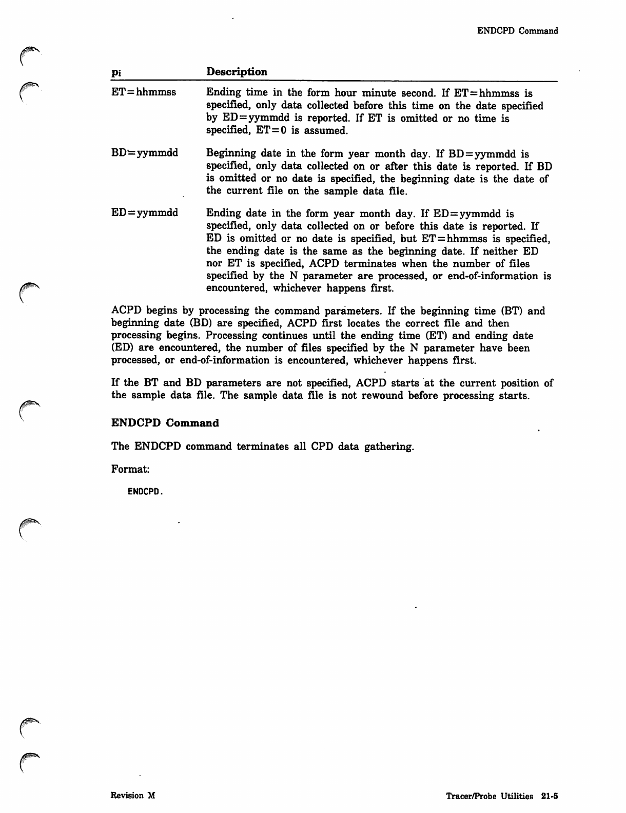
ET=hhmmss Ending time in the form hour minute second. If ET=hhmmss is
specified, only data collected before this time on the date specified
by ED=yymmdd is reported. If ET is omitted or no time is
specified, ET=0 is assumed.
BD^= yymmdd Beginning date in the form year month day. If BD=yymmdd is
specified, only data collected on or after this date is reported. If BD
is omitted or no date is specified, the beginning date is the date of
the current file on the sample data file.
ED=yymmdd Ending date in the form year month day. If ED=yymmdd is
specified, only data collected on or before this date is reported. If
ED is omitted or no date is specified, but ET=hhmmss is specified,
the ending date is the same as the beginning date. If neither ED
nor ET is specified, ACPD terminates when the number of files
specified by the N parameter are processed, or end-of-information is
encountered, whichever happens first.
ACPD begins by processing the command parameters. If the beginning time (BT) and
beginning date (BD) are specified, ACPD first locates the correct file and then
processing begins. Processing continues until the ending time (ET) and ending date
(ED) are encountered, the number of files specified by the N parameter have been
processed, or end-of-information is encountered, whichever happens first.
If the BT and BD parameters are not specified, ACPD starts at the current position of
the sample data file. The sample data file is not rewound before processing starts.
ENDCPD Command
The ENDCPD command terminates all CPD data gathering.
Format:
ENDCPD.
Revision M Tracer/Probe Utilities 21-5
ICPD Command
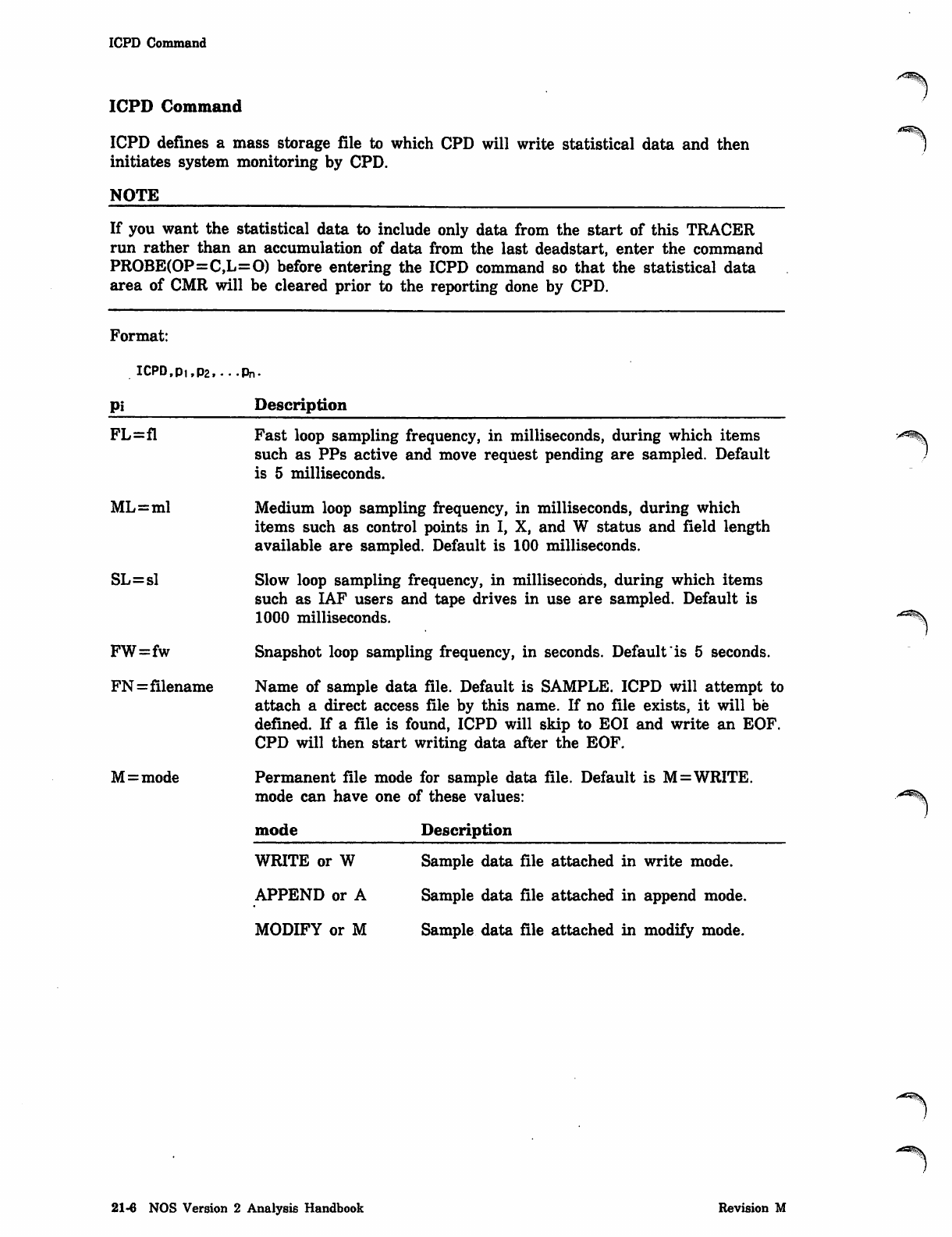
ICPD Command
ICPD defines a mass storage file to which CPD will write statistical data and then
initiates system monitoring by CPD.
NOTE
If you want the statistical data to include only data from the start of this TRACER
run rather than an accumulation of data from the last deadstart, enter the command
PROBE(OP=C,L=0) before entering the ICPD command so that the statistical data
area of CMR will be cleared prior to the reporting done by CPD.
. A ^ S
Format:
lCPD,p1,p2,...pn.
Pi Description
FL=fl
ML=ml
SL=sl
FW=fw
FN=filename
M=mode
Fast loop sampling frequency, in milliseconds, during which items
such as PPs active and move request pending are sampled. Default
is 5 milliseconds.
Medium loop sampling frequency, in milliseconds, during which
items such as control points in I, X, and W status and field length
available are sampled. Default is 100 milliseconds.
Slow loop sampling frequency, in milliseconds, during which items
such as IAF users and tape drives in use are sampled. Default is
1000 milliseconds.
Snapshot loop sampling frequency, in seconds. Default "is 5 seconds.
Name of sample data file. Default is SAMPLE. ICPD will attempt to
attach a direct access file by this name. If no file exists, it will be
defined. If a file is found, ICPD will skip to EOI and write an EOF.
CPD will then start writing data after the EOF.
Permanent file mode for sample data file. Default is M=WRITE,
mode can have one of these values:
mode Description
WRITE or W
APPEND or A
MODIFY or M
Sample data file attached in write mode.
Sample data file attached in append mode.
Sample data file attached in modify mode.
^ = ^ v
21-6 NOS Version 2 Analysis Handbook Revision M
ICPD Command
NOTE
If the sample data file is attached in write mode, the file cannot be accessed until
ENDCPD is run. If the sample data file is to be accessed while data is being collected,
append or modify mode must be specified. In this situation, the file may be attached in
read/allow modify (RM) mode. (Attaching the file in write mode rather than in modify
or append mode expends less overhead when interlocking and writing the data file.)
If a loop time is set to 0 (zero), no samples for that loop will be taken. If the data
block sample time is set to 0 (zero), the data file will be written only when the
sampling interval terminates.
All numeric data should lie within the range 0 through 4095 (0 through 7777s).
Revision M Tracer/Probe Utilities 21-7
Output File Format
Output File Format
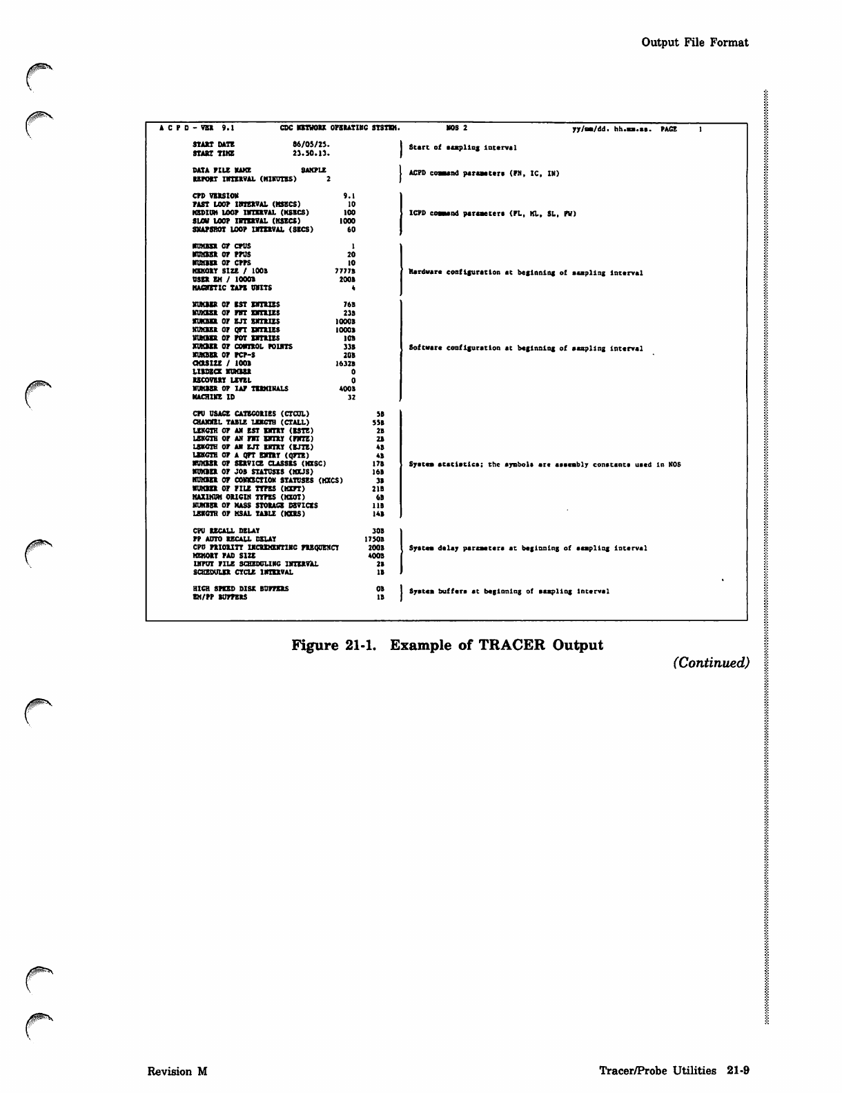
The first three pages of the output report produced by ACPD contain the header block
information. Next the data items are reported for fast, medium, and slow loop samples.
The report ends with the snapshot data items.
Figure 21-1 is an example showing the format of the output report. The example has
been simplified and condensed to reduce the amount of output. Also, supporting text
has been added to the example.
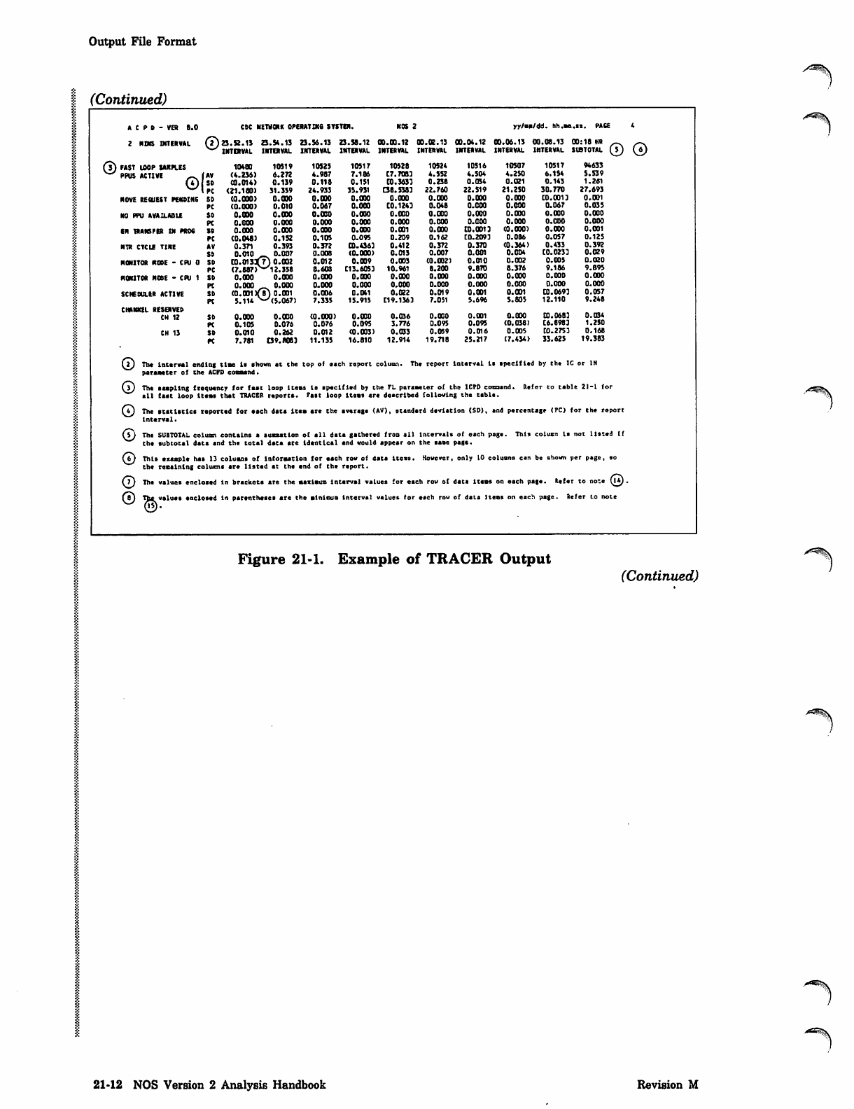
Data items monitored at successive time intervals are listed in the same row. For each
data item, the average, standard deviation, and percentage are listed in successive
rows. Up to 10 intervals can be listed per page in successive vertical columns. If the
output file contains more than 10 columns per row, the output report lists the first 10
columns for all rows of data items and then resumes listing subsequent intervals
following the snapshot data items.
The SUBTOTAL column contains the values of the data items for the time spanned by
the preceding intervals on the current page; that is, the time spanned by the preceding /"!3%
intervals is considered one interval. The TOTAL column appears after the last interval /
reported and contains the statistical values of the data items for the entire run. The
SUBTOTAL column is not listed if the subtotal data and total data are identical and
would appear on the same page. In this case, only the TOTAL column is listed. The
SUBTOTAL and TOTAL columns are not reported for the snapshot data items. The
♦MAX* and *MIN* columns appear at the end of the report and contain the maximum
and minimum interval values of the data items for the entire run. The maximum and
minimum interval values on each page are indicated by brackets and parentheses,
respectively.
The average is not reported for data items that have a weighting factor of 1, and the
percentage is not reported for data items that have a weighting factor of 100, since
this information is redundant.
21-8 NOS Version 2 Analysis Handbook Revision M
Output File Format
* c p d - v b i 9 . 1 c d c b e t h o u o p e i a t i h c s y s t e m . KOS 2 yy/as/dd. hh.ss.sa. P A C E 1
SUXn DATE 86/0S/2J. Start of eespling Interval
START TUB 23.50.13.
DATA PILE HAKE SAKPLE ACPD coaaand paraaeter* (FN, IC, IN)
EEPOET IMTXBVAL (H1KUIES) 2
CPD VEESION 9.1
PAST LOOP ItRBEVAL (KSBCS) 10
ksdioh loop nmtEVAi. (ksecs) 100 ICPD coaaend paraaeter* (PL, KL, SL, PW)
sum loop nrravAL (ksecs) iooo
SNAPSHOT LOOP URIEVAL (SECS) 60
■DMBEB OP CPUS 1
most op ppus 20
nnnn op cpps 10
KEKOET SIZE / 100B 7777B Hardware coofIguratton at beginning of aaspllng Interval
USEE EM / 1000B 200B
KAOtETlC TAPE OBITS *
N U M B E R O P E S T E H T U E S 7 6 B
K U K E S E O P P B T E R T E I E S 2 3 8
man op ejt sxibizs iooob
mnasE op qtt bcteies iooob
HUHESK OP POT ENTEIZS 10B
kukbee op cuheol poutts 33s Software configuration at beginning of aaspllng interval
XlMBBft OP PCP-S 20B
QOSXZE / 1001 1632B
ludzce xuxbsb 0
UCOVBET LEVEL 0
KIMEBB OP UP TUKIHAIS 4008
KACRXKE ID 32
CPU USACE CATBCOEIES (CTCOL) SB
(BANJUL TABLE LEKCTB (CTALL) 5SB
LEKCTH OP AM EST BKTBT (ESTE) 2B
LEKOTB OP AN PIT EWXBY <FHTE) 2B
LEKCTH OP Al EJT BRET <BJTE) 48
lekcth op a art EKTtT (qPTE) 48
mnasK op sekvice classes (mxscj 17B Spates atatlstlca: the ajntbol* ate aaaeablv conatant* uaed in KOS
mnan op job statuses acus) 16B
HUMBEE OP COWECTIOK STATUSES (HXCS) 3B
mnan or pile ttpes (mxpt) 21B
KAXIKUM OUCIH TYPES (HZOT) 6B
HMB8B OP MASS STOEACE DEVICES 11B
LENGTH OP MSAL TABLE (MOS) 14B
CPO EECALL DELAY 30B
PP ADTO EECAIL DELAY 17508
CPO PBIOUTT INCEEHENTIRC PBBqOEKCT 2008 . Spates del*7 pareaetera at beginning of aaatpllng Interval
KEKOET PAD SIZE 4008
UPUT PILE SCHEDULING IHIEEWU. 28
SCHEDULE! CYCLE IIREBVAL IB
HIGH SPEED DISE BOPPEtS
BM/PP BOPPEES
08
IB Systca buffer* at beginning of aaspllng Interval
Figure 21-1. Example of TRACER Output (Continued)
Revision M Tracer/Probe Utilities 21-9
Output File Format
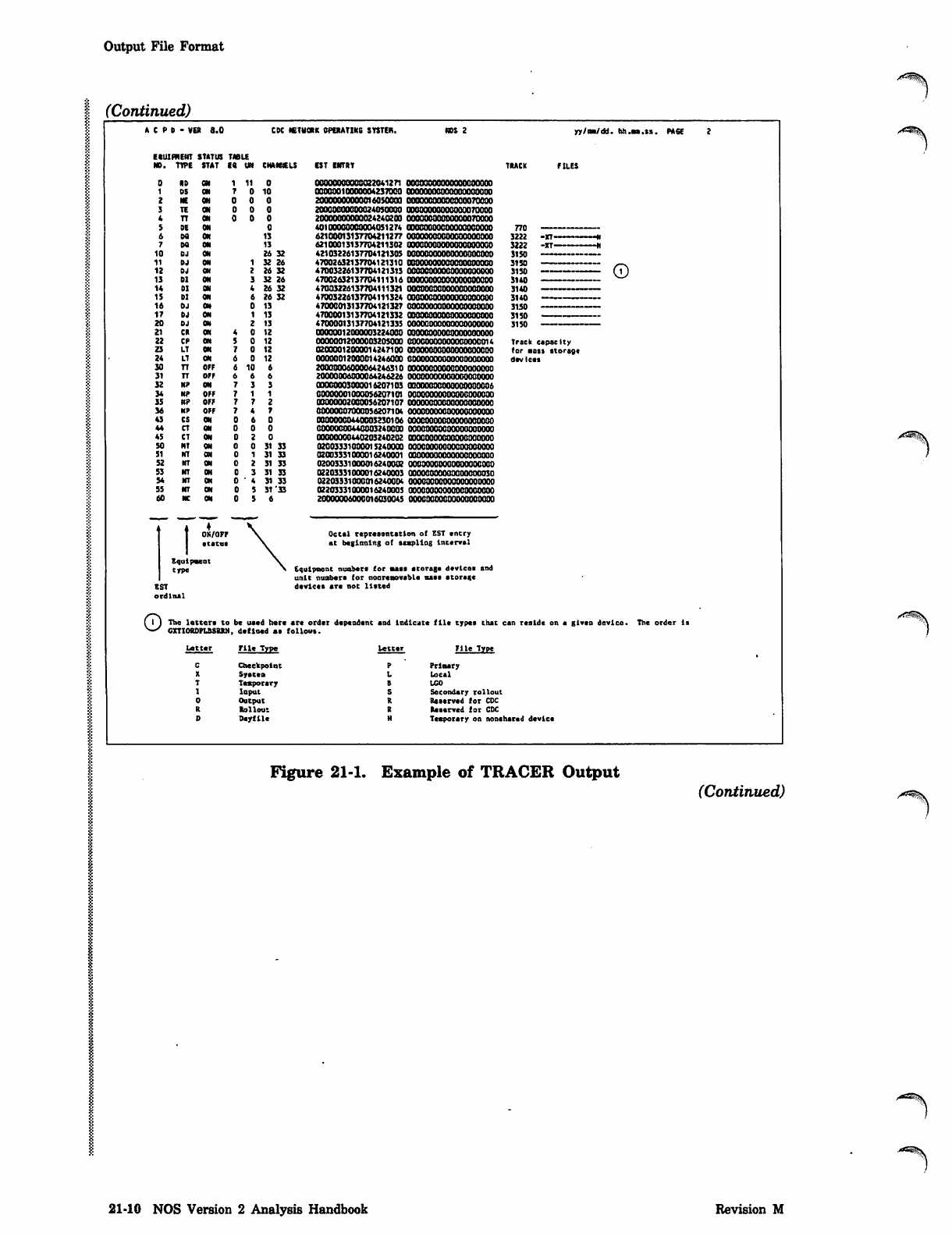
(Continued)
A C P 0 - VE* 6.0 CK mUOVt OPERATING SYSTEfl.
EttURHEHT STATUS TABU
NO. TTPE STAT 18 UN CHANNELS
ON
ON
ON
OFF
OFF
ON
OFF
OFF
OFF
ON
ON
ON
ON
1 0
0 1 0
0 0
0 0
0 0
0
13
13
26 32
1 32 26
2 26 32
3 32 26
4 26 32
6 26 32
0 13
1 13
2 13
0 12
0 12
0 12
0 12
0 6
0
0
0
31 33
31 33
31 33
31 33
31 33
31 '33
CST ENTRY
00000000000022041271
00000010000004237000
200000000000160SOOOO
20000000000024050000
200000O00O0O2424O200
40100000000004051274
62100013137704211277
62100013137704211302
42103226137704121305
47002632137704121310
47003226137704121313
47002632137704111316
47003226137704111321
47003226137704111324
47000013137704121327
47000013137704121332
47000013137704121335
00000012000003224000
00000012000003205000
02000012000014247100
00000012008014246000
20000006000064246S10
20000006000064246226
00000003000016207103
00000001000056207101
O300O00200O0S6207107
00000007000056207104
00000000440003230106
00000000440003240000
00000000440203240202
02003331000015240000
02003331000016240001
02003331000016240002
02203331000016240003
02203331000016240004
02203331000016240005
20000006000016O30O4S
00000000000000070000
0000000(1000000070000
oooooooooooooooooooo
oooooooooooooooooooo
0O0CO0OOOOO0OO0OOOG0
OOOOOOOOOOOOOOOOOOOO
OOOOOOOOOOOOOOOOOOOO
OOOOOOOOOOOOOOOOOOOO
000O00OOOO0OO0O0OO14
OOOOOOOOOOOOOOOOOOOO
OOOOOOOOOOOOOOOOOOOO
OOOOOOOOOOOOOOOOOOOO
00000000000000000006
oooooooooooooooooooo
oooooooooooooooooooo
oooooooooooooooooooo
oooooooooooooooooooo
oooooooooooooooooooo
00000000000000000030
oooooooooooooooooooo
oooooooooooooooooooo
oooooooooooooooooooo
T ♦ ♦
T O N
Equipment
trpe
0N/0F7
•tatu*
EST
ordinal
Octal representation of EST encry
at beginning of stapling interval
Equipment umbers for nas* storage devices and
unit nunbers for nonremovable u*s storsi*
devices are not listed
yy/aa/dd. hh.sa.ts. PACE
Track capacity
for s a il st o rag e
devices
oThe letter* to be used here ar* order dependent and indicate file types that can reside on a given device.
CXTIOEDPLBSBBN, defined as follows.
letter File Type
P Prlsary
L Local
8 L G O
S Secondary rollout
R R e s e r v e d f o r C D C
S Reserved for CDC
N Temporary on nonshared device
The order Is
cCheckpoint
XSystea
TTemporary
1Input
0Output
REollout
DDayfile
A^^S
Figure 21-1. Example of TRACER Output (Continued)
21-10 NOS Version 2 Analysis Handbook Revision M
Output File Format
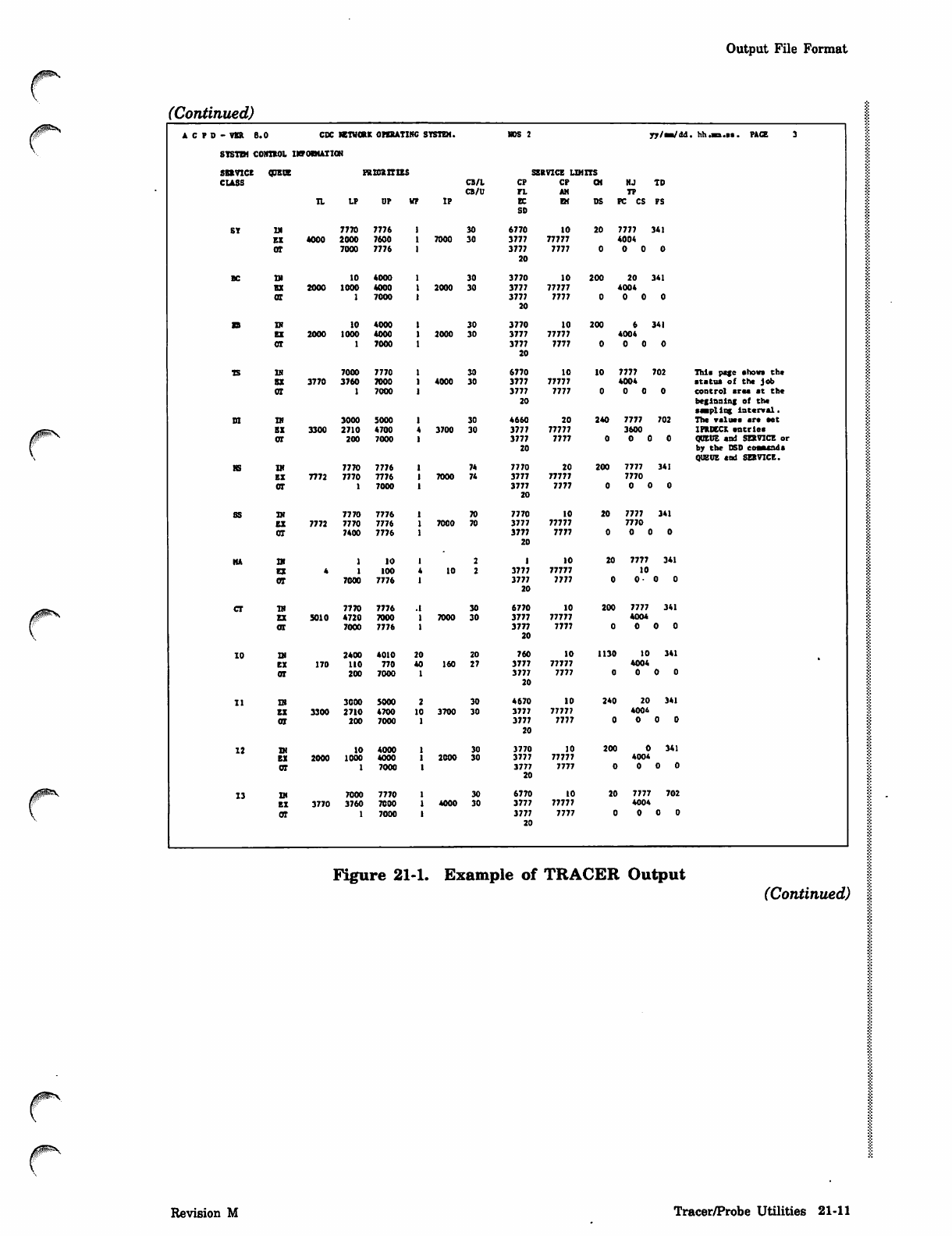
(Continued)
A C P D - VSR B CDC KTWOBX OPERATING SYSTEM. NOS 2 yv/sB/dd . hh. * B .»s . PAC E 3
SYSTBl CONTEOL IKPOWATIOH
SBEVICE ODETJE ps ids Iras SERVICE LIMITS
CLASS CB/L
CB/U
CP
PL
CP
AM
CM NJ
TP
TD
TL LP UP VF IP EC
SD
EM DS FC CS PS
SY IN 7770 7776 30 6770 10 20 7777 341
EE 4000 2000 7600 7000 30 3777 77777 4004
OT 7000 7776 3777
20
7777 0 0
BC 10 4000 30 3770 10 200 20 341
BE 2000 1000 4000 2000 30 3777 77777 4004
at 7000 3777
20
7777 0 0
EB TN 10 4000 30 3770 10 200 341
EE 2000 1000 4000 2000 30 3777 77777 4004
CT 7000 3777
20
7777 0 0
TS IH 7000 7770 30 6770 10 10 7777 702 This page ahows th*
EE 3770 3760 7000 4000 30 3777 77777 4004 status of the job
OT 7000 3777
20
7777 0 0 control area at the
beginning of the
stapling Interval.
DI IN 3000 5000 30 4660 20 240 7777 702 The value* are set
EE 3300 2710 4700 3700 30 3777 77777 3600 IFRtCCX entrle*
OT 200 7000 3777
20
7777 0 0 QUEUE and SERVICE or
by the DSD eoaaeada
QUEUE and SERVICE.
HS IN 7770 7776 74 7770 20 200 7777 341
EE 7772 7770 7776 7000 74 3777 77777 7770
OT 7000 3777
20
7777 0 0
SS IN 7770 7776 70 7770 10 20 7777 341
EE 7772 7770 7776 7000 70 3777 77777 7770
OT 7400 7776 3777
20
7777 o a
HA 10 10 20 7777 341
EX 100 10 3777 77777 10
OT 7000 7776 3777
20
7777 0- 0 0
cr TJ) 7770 7776 .1 30 6770 10 200 7777 341
EX 5010 A720 7000 7000 30 3777 77777 4004
OI 7000 7776 3777
20
7777 0 0
10 IN 2400 4010 20 20 760 10 1130 10 341
EX 170 110 770 40 160 27 3777 77777 4004
OT 200 7000 3777
20
7777 0 0
11 IB 3000 5000 30 4670 10 240 20 341
EE 3300 2710 4700 10 3700 30 3777 77777 4004
OT 200 7000 3777
20
7777 0 0
12 TJ) IO 4000 30 3770 10 200 341
EX 2000 1000 4000 2000 30 3777 77777 4004
OT 7000 3777
20
7777 0 0
13 Qi 7000 7770 30 6770 10 20 7777 702
EX 3770 3760 7000 4000 30 3777 77777 4004
OT 7000 3777
20
7777 0 0
Figure 21-1. Example of TRACER Output
(Continued)
Revision M Tracer/Probe Utilities 21-11
Output File Format
1 (Continued)
j/^%\
A C P D - V E R 8 . 0 CDC NEWONK OPERAT DCS SYSTEM. NOS 2 y y / a a / d d . h h . s a . s s . P A C E 4
2NINS INTERVAL 23.52.13 23.54.13 23.56.13 23.58.12 00.0 0 . 12 00.0 2 .13 00.04.12 00.06.13 00.08 . 1 3 00 : 1 8 I f fi _ ~ .
INTERVAL INTERVAL INTERVAL INTERVAL INTERVAL INTERVAL INTERVAL INTERVAL INTERVAL SUBTOTAL (^5J \6)
( ? ) F A S T
v ^ P P U S LOOP SAKPLES 10480 1051V 10525 10517 10528 10524 10516 10507 10517 94633
ACTIVE ,_ (AV ( 4 . 2 3 6 ) 6 . 2 7 2 4.987 7.166 C 7 . 7 0 S 3 4 . 5 5 2 4.504 4.250 6.154 5.539
OSO (0.014) 0.139 0 . 118 0.151 C O. 3 6 3 3 0. 2 3 8 0.034 0.021 0.143 1.261
PC (21.180) 31.359 24.933 35.931 (38.5383 22.760 22.519 21.250 30.770 27.693
MOVE REQUEST PENDING SD ( 0 . 0 0 0 ) 0 . 0 0 0 0.000 0.000 0 . 0 0 0 0 . 0 0 0 0.000 0.000 C0.0013 0.001
PC ( 0 . 0 0 0 ) 0 . 0 1 0 0.067 0.000 CO . 1 2 4 3 0 . 0 48 0.000 0.000 0.067 0.035
NO FPU AVAILABLE SO 0.000 0.000 0.000 0.000 0 . 0 0 0 0 . 0 0 0 0.000 0.000 0.000 0.000
PC 0.000 0.000 0.000 0.000 0 . 0 0 0 0 . 0 0 0 0.000 0.000 0.000 0.000
EN TRANSFER IN PROS so 0 . 0 0 0 0 . 0 0 0 0.000 0.000 0 . 0 0 1 0 . 0 0 0 C0.0013 CO.000) 0.000 0.001
PC (0.048) 0.152 0.105 0.095 0 . 2 0 9 0 . 1 6 2 [0.2093 0.086 0.057 0.125
NTS CYCLE TINE AV 0 . 3 7 1 0 . 3 9 3 0.372 03.436) 0.412 0.372 0.370 (0.364) 0.433 0.392
SB 0 . 0 1 0 _ 0 . 0 0 7 0.008 (0.000) 0 . 0 1 3 0 . 0 0 7 0.001 0.004 C0.0233 0.029
HMITOR R ODE - CP U 0 SO 10.01317) 0.002
(7.687>N-y12.358
0.012 0.009 0 . 0 0 3 ( 0 . 0 0 2 ) 0.010 0.002 0.005 0.020
PC 8.603 C13.6053 1 0 . 9 6 1 8 . 2 0 0 9.870 8.376 9.186 9.895
FtONITOR HOBE - CPU 1 SO 0.000 0.000 0.000 0.000 0 . 0 0 0 0 . 0 0 0 0.000 0.000 O.OOD 0.000
PC 0 . 0 0 0 _ 0 . 0 0 0 0.000 0.000 0 . 0 0 0 0 . 0 0 0 0.000 0.000 0.000 0.000
SCHEMILER ACTIVE SO (0.001 )(8) 0.001
5.114 v-/(5.067)
0.006 0.041 0 . 0 2 2 0 . 0 1 9 0.001 0.001 CO.0693 0.057
PC 7.333 15.915 C19.1363 7.091 5.696 5.605 12.110 9.246
CHANNEL RESERVED
CH 12 SD 0.000 0.000 (0.000) 0.000 0 . 0 3 6 0 . 0 0 0 0.001 0.000 CO. 0683 0.034
PC 0 . 1 0 5 0 . 0 7 6 0.076 0.095 3 . 7 7 6 0 . 0 9 5 0.095 (0.038) C6.8983 1.250
CH 13 so 0 . 0 1 0 0 . 2 6 2 0.012 (0.003) 0 . 0 3 3 0 . 0 5 9 0.016 O.OQS C0.2753 D.16S
PC 7.781 £39.«0S3 11.135 16.810 12.914 19.718 25.217 (7.434) 33.625 19.383
OT h e I n t e r v a l e n d i n g t i m e i s s h o w n a t t h e top ol each report coition. The report In t erv a l 1* sp e cifi ed by the IC or IN
paraaeter of the ACPD command.
OThe sampling frequency for fast loop Items Is specified by the TL parameter of the ICPD coeosnd. Re er to table 2 1-1 for
t i l f a s t l o o p t t * a s that TRACER reports. Fast loop Item* are described following the table.
©The statistics reported for each data Item are the average (AV), standard deviation (SD), end percentage (PC) for the report
I n t e r v a l .
©The SUBTOTAL column contains a summation of el l d ata g a ther e d fro n e ll lnt e rvi l i of etch page. This colu mn Is not listed If
the subtotal data and the total data are i d e n t i c a l and troul< appear on the esoe page.
©This example has 13 columns of Informstion for each rov of dat* ttcts. However only 10 coitions can be shown pe r psge, so
the remaining caluims *r* listed at the end of the report.
©The values enclosed in brackets are the maximum Interval values for each rov of dots items on each page. Refer to note 0*) .
©The value* enclosed
©■
In parentheses are the minimum I n t e r v a l values for etch row of date Items on each page. Kef er lo note
Figure 21-1. Example of TRACER Output (Continued)
21-12 NOS Version 2 Analysis Handbook Revision M
Output File Format
y^^S
(Continued)
0pS
_ eeeeeeeeeee—«««»««««»
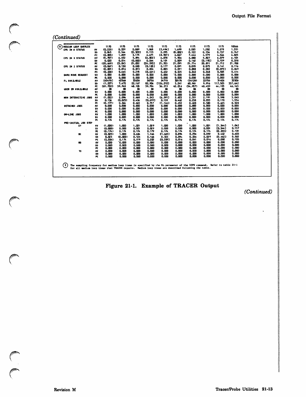
(9) HEDIUR IDOP SJUtB.ES
^^ CPS IN M STATUS 1170 .1175 1175 1173 1175 1175 1175 1173 1175 10566
AV (0.225) 0.339 0.889 1.868 C2.4943 1.699 2.085 1.282 1.27B 1.351
SD 0.043 0.144 CO.3203 0 . 113 0.293 (0.002) 0.122 0.134 0.137 0.747
PC (0.805) 1.209 3.175 6.671 C8.9073 6»067 7.446 4.579 4.566 4.825
CPS IN X STATUS AV (5.7B7) 6.452 5.894 C6.CD23 6.078 5.906 6.080 5.827 6.079 6.101
SD 0.020 0.014 (0.003) 0.044 0.101 0.009 0.162 C0.1903 0.159 0.328
PC (20.669) 23.043 21.052 Q4.2933 21.705 21.091 21.714 20.811 21.712 21.788
CPS IN 1 STATUS AV (0.067) 0.130 0.083 C0.18S3 0.177 0.091 0.09S 0.075 0.141 0.116
SD (0.031) 0.016 0.015 0.004 0.005 0.011 0.008 0.002 CO.0753 0.049
PC (0.238) 0.465 0.295 CO. 6613 0.632 0.325 0.340 0.268 0.505 0.414
SANE NOVE REfiUEST SO O.OOO 0.000 0.000 0.000 0.000 '0.000 0.000 0.000 O.OOO 0.000
PC 0.000 0.000 0.000 0.000 0.000 0.000 0.000 0.000 0.000 0.000
FL AVAILABLE AV [434703 42366 3363B 2675D 2471B 3017B (2412B) 33738 314QB 32508
SD (1.227) 7.470 22.167 82.904 C126.2103 5.241 60.961 9.916 117.505 337.642
PC C61.H03 59.740 48.185 39.794 36.213 42.016 (34.957) 48.459 44.173 46.143
USER EH AVAILWLE AV OB OS 03 03 OB oa 03 oa 03 03
SD 0.000 0.000 0.000 0.000 0.000 0.000 O.OOO 0 . 0 0 0 0 .000 0 .00 0
PC 0.000 0.000 0.000 0.000 0.000 0.000 0.000 0.000 0.000 0.000
NON INTERACTIVE JOBS AV (1.022) 2.096 2.668 4.243 C6.S913 2.603 2.351 2.191 3.598 3.O40
SD 0.136 (0.023) 0.456 CQ.6193 0.139 0.462 0.258 0.033 0.178 1.556
PC (0.177) 0.364 0.463 0.737 C1.1441 0.452 0.408 0.380 0.625 0.528
DETACHED JOOS AV 0.000 0.000 0.000 0.000 0.000 0.000 0.000 0.000 0.000 0.000
SD 0.000 0.000 0.000 0.000 0 .000 0.000 O.OOO 0.000 0.000 0.000
PC 0.000 0.000 0.000 0.000 0.000 0.000 0.000 0.000 0.000 0.000
ON-LINE JOBS AV 1.000 1.000 1.000 1.000 1.000 1.000 1.000 1.000 1.000 1.000
SD 0.000 0.000 0.000 0.000 0.000 0.000 0.000 0.000 0.000 0.000
PC 0.174 0.174 0.174 0.174 0.174 0.174 0.174 0.174 0.174 0.174
PRE-INIT1AL JOB STEP
ST AV (1.000) 1.000 1.001 1.029 1.000 1.000 1.000 1.001 C1.3441 1.042
SD (0.000) 0.000 0.001 0.029 0.000 0.000 0.000 0.001 C0.3443 0.157
PX (0.174) 0.174 0.174 0.179 0.174 0.174 0.174 0.174 CO. 233) 0.181
BC AV (0.025) 1.000 0.684 1.166 C1.6653 0.094 0.236 0.092 0.462 0.603
SD 0.025 (O.OOO) 0.125 0.166 0.335 0.0*. 0.23 6 0 . 0 2 9 CO.4623 0.582
PC (0.004) 0.174 0.11 9 0.202 C0.2893 0.016 0.041 0.016 0.080 0.105
RB AV 0.000 'O.OOO O.OOO 0.000 O.OOO 0.000 0.000 0.000 0.000 0.000
SD 0.000 0.000 0.000 0.000 0.000 0.000 0.000 0.000 0.000 0.000
PC 0.000 . 0.000 0.000 O.OOO 0.000 0.000 0.000 0.000 0.000 0.000
TS AV 0.000 0.000 0.000 0.000 0.000 0.000 0.000 0.000 0.000 0.000
SD O.OOO 0.000 0.000 0.000 0.000 0 .000 0.000 0 . 0 0 0 0.000 0.000
PC 0.000 0.000 0.000 0.000 0.000 0.000 0.000 0.000 0.000 0.000
(9J The eaapllog frequency
^"^ tor all medium loop it (or medium loop Items is specified by the HL psraaecer of the ICPD cosaand. R e f er to table 21-1
em* thee TRACER reports. Hedium loop items are described following the teble.
Figure 21-1. Example of TRACER Output (Continued)
Revision M Tracer/Probe Utilities 21-13
Output File Format
1 (Continued)
_. easaeaeeseaeasas******
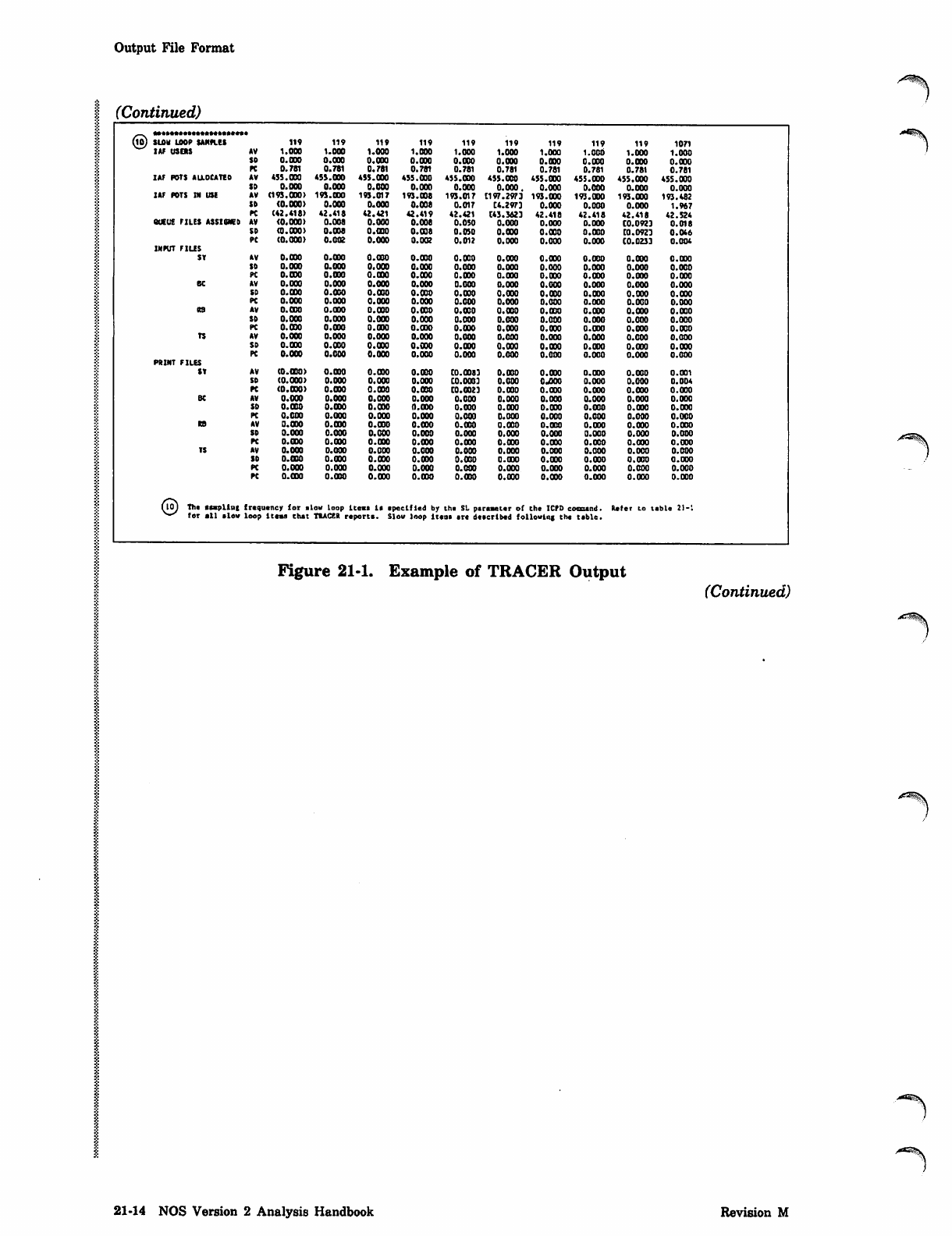
MO) SUM LOOP SANPLES
IAF USERS
119 119 119 119 119 119 119 119 119 1071
AV 1.000 1.000 1.000 1.000 1.000 1.000 i.ooo 1.000 1.000 1.000
SO 0.000 0.000 0.000 0.000 0 .000 0.030 O.OOO O.OOO 0.000 0.000
PC 0.781 0.781 0.781 0.781 0.781 0.781 0.781 0.781 0.781 0.781
IAF PDTS ALLOCATED AV 435.000 453.000 455.000 455.000 455.000 455.030 455.000 455.000 455.000 455.000
SD 0.000 0.000 0.000 0.000 0.000 0.000. 0.000 0.000 0.000 0.000
IAF PDTS IN USE AV (193.000) 193.000 193.017 193.008 193.017 Cl97.2973 193.000 193.000 193.000 193.462
SD (0.000) 0.000 0.000 0.008 0.017 C4.2973 0.000 0.000 0.000 1.967
PC (42.418) 42.418 42.421 42.419 42.421 C43.3623 42.418 42.418 42.418 42.524
QUEUE FILES ASSIGNED AV (0.000) 0.008 0.000 0.008 0.050 0.000 0.000 0.000 C0.0923 0.018
SD (0.000) 0.008 0.000 0.008 0.050 0.000 O.OOO 0.000 CO. 0923 0.046
PC (0.000) 0.002 0.000 0.002 0.012 0.000 0.000 0.000 CO.0233 0.004
INPUT FILES
SY AV 0.030 0.000 0.000 0.030 O.OOO 0.000 0.000 0.00 0 0.000 0.000
SO 0.000 0.000 0.000 O.OOO 0.000 0.000 0.000 0.000 0.0 00 0.000
PC 0.000 0.000 0.030 0.030 0.000 0.030 0.000 0.030 0.000 0.000
BC AV 0.000 0.000 0.000 0.000 0.000 0.000 0.000 0.000 0.000 0.000
SD 0.000 0.000 0.000 0.030 0.030 0.030 0.030 0.000 0.000 0.000
PC 0.000 0.000 0.000 0.000 0.000 0.000 0.000 0.000 0.000 0.000
RB AV O.OOO O.OOO 0.000 0.030 0.000 O.OOO 0.030 0.030 0.000 0.000
SD 0.000 0.000 0.000 0.000 0.000 0.000 0.000 0.000 0.000 0.000
PC 0.000 0.090 0.000 0.000 0.000 0.030 0.030 0.030 0.000 0.000
TS AV 0.000 0.000 0.000 0.000 0.000 0.000 0.000 0.000 0.000 0.000
SO 0.000 0.000 O.OOO 0.000 O.OOO 0.000 0.030 0.030 0.030 0.000
PC 0.000 O.OOO 0.000 0.000 0.000 0.000 0.000 0.000 0.000 O.OOO
PRINT FILES
ST AV (0.000) O.OOO 0.000 O.OOO C0.00J3 0.000 0.030 0.000 0.000 0.001
SO (0.000) 0.000 0.000 0.000 C0.00B3 0.000 OJQOO 0.000 0.000 0.004
PC (0.000) O.OOO 0.030 O.OOO C0.O023 0.000 0.030 0.000 0.000 0.000
BC AV 0.000 0.000 0.000 0.000 0.000 0.000 0.000 0.000 0.000 0.000
SD 0.000 0.000 0.000 O.OOO 0.000 0.030 0.000 0.000 0.030 0.000
PC 0.000 0.000 O.OOO 0.000 0.000 0.000 0.000 0.000 0.000 0.000
RS AV 0.000 0.000 0.000 0.000 0.030 0.030 0.000 0.000 0.030 0.000
SD 0.000 0.000 0.000 0.000 0.000 0.000 0.000 0.000 0.000 0.000
PC O.OOO 0.000 0.000 0.000 0.030 O.OOO 0.03 0 0.030 0.000 0.030
TS AV 0.000 0.000 0.000 0.000 0.000 0.000 0.000 0.000 0.000 0.000
SO 0.000 0.000 0.000 0.030 0.030 0.000 0.030 0.000 0.000 0.000
PC 0.000 0.000 0.000 0.000 0.000 0.000 0.000 0.000 0.000 0.000
PC O.OOO O.OOO 0.000 O.OOO O.OOO 0.000 0.000 0.000 0.000 0.000
(io) The stapling
v-^ for all slow frequency for slow loop items it specified by the SL peraaeter of the ICPD cososnd. Refer to tsble 21-'.
loop items that TRACER reports. Sl ow loop ltcos sr* described following the tsble.
Figure 21-1. Example of TRACER Output
(Continued)
21-14 NOS Version 2 Analysis Handbook Revision M
Output File Format
(Continued)
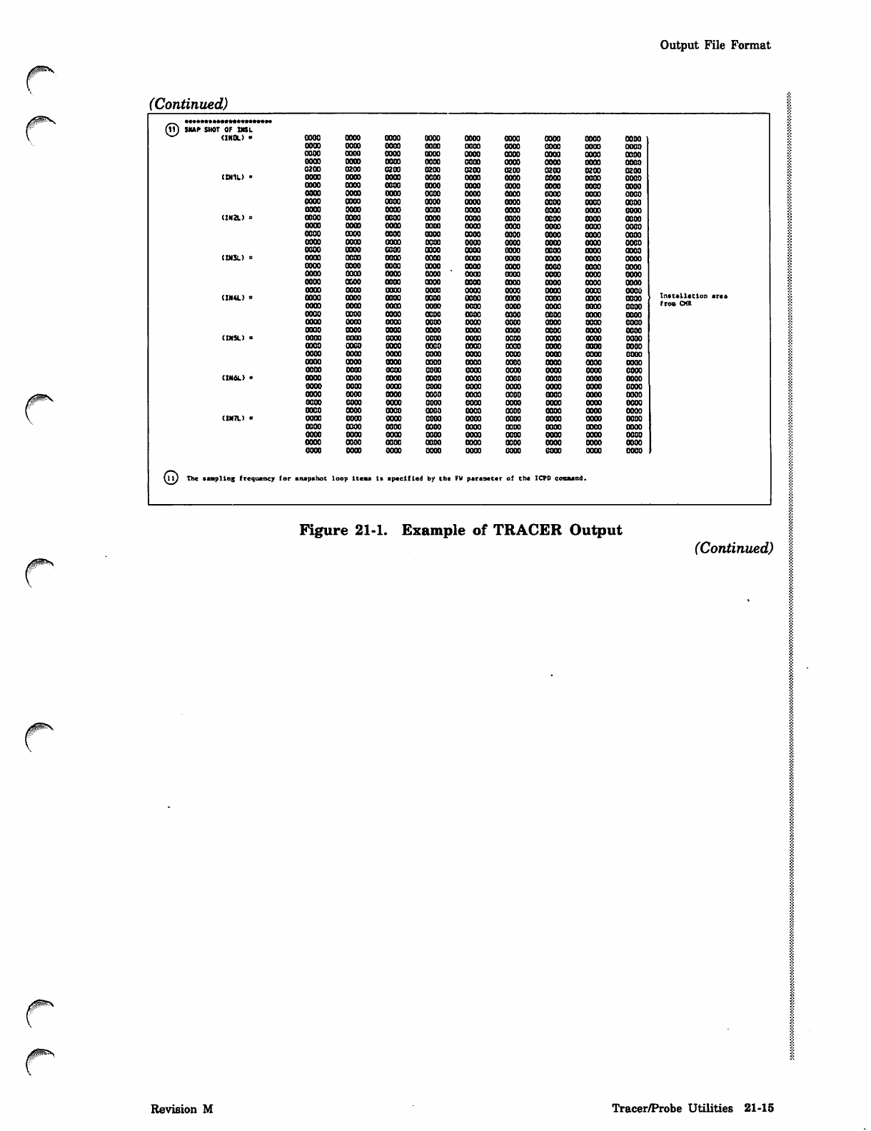
©•*•*»••••••»*»*••••»•»
SNAP SHOT OF INS L
(INOL) ■OOOO oooo oooo oooo oooo oooo oooo oooo oooo
OOOO oooo 0000 OODO oooo oooo oooo oooo oooo
OOOO oooo OOOO OOOO oooo oooo oooo oooo oooo
OOOO oooo OOOO OOOO oooo oooo oooo oooo oooo
0200 0200 0200 0200 0200 0200 0200 0200 0200
(IN1L) • oooo oooo oooo oooo oooo oooo oooo oooo oooo
oooo oooo oooo oooo oooo oooo oooo oooo oooo
oooo oooo oooo oooo oooo oooo oooo oooo oooo
oooo oooo oooo oooo oooo oooo oooo oooo oooo
oooo oooo oooo oooo oooo oooo oooo oooo oooo
(IN2L) = oooo oooo oooo oooo oooo oooo oooo oooo oooo
oooo oooo oooo oooo oooo oooo oooo oooo oooo
oooo oooo oooo oooo oooo oooo oooo oooo oooo
oooo oooo oooo oooo oooo oooo oooo oooo oooo
oooo oooo oooo oooo oooo oooo oooo oooo oooo
(IN3L) = oooo oooo oooo oooo oooo oooo oooo oooo oooo
0300 oooo oooo oooo oooo oooo oooo oooo oooo
oooo oooo oooo OOOO ' oooo oooo oooo oooo oooo
oooo oooo OOOO OOOO oooo oooo oooo oooo oooo
oooo oooo OOOO oooo oooo oooo oooo oooo oooo
(IN4L) > oooo oooo oooo oooo oooo oooo oooo oooo oooo Instslletlon ares
oooo oooo oooo oooo oooo oooo oooo oooo oooo from CMt
oooo OBOO oooo oooo oooo oooo oooo oooo oooo
oooo oooo oooo oooo oooo oooo oooo oooo oooo
oooo oooo oooo oooo oooo oooo oooo oooo oooo
(INSL) = oooo oooo oooo oooo oooo oooo oooo oooo oooo
oooo oooo oooo oooo oooo oooo oooo oooo oooo
oooo oooo oooo oooo oooo oooo oooo oooo oooo
oooo oooo oooo oooo oooo oooo oooo oooo oooo
oooo oooo oooo oooo oooo oooo oooo oooo oooo
(1H6L) * oooo oooo oooo oooo oooo oooo oooo oooo oooo
oooo oooo oooo oooo oooo oooo oooo oooo oooo
oooo oooo oooo oooo oooo oooo oooo oooo oooo
oooo oooo oooo oooo oooo oooo oooo oooo oooo
oooo oooo oooo oooo oooo oooo oooo oooo oooo
(IN7L) x oooo oooo oooo oooo oooo oooo oooo oooo oooo
oooo oooo oooo oooo oooo oooo oooo oooo oooo
oooo oooo oooo oooo oooo oooo oooo oooo oooo
oooo oooo oooo oooo oooo oooo oooo oooo oooo
oooo oooo oooo oooo oooo oooo oooo oooo oooo
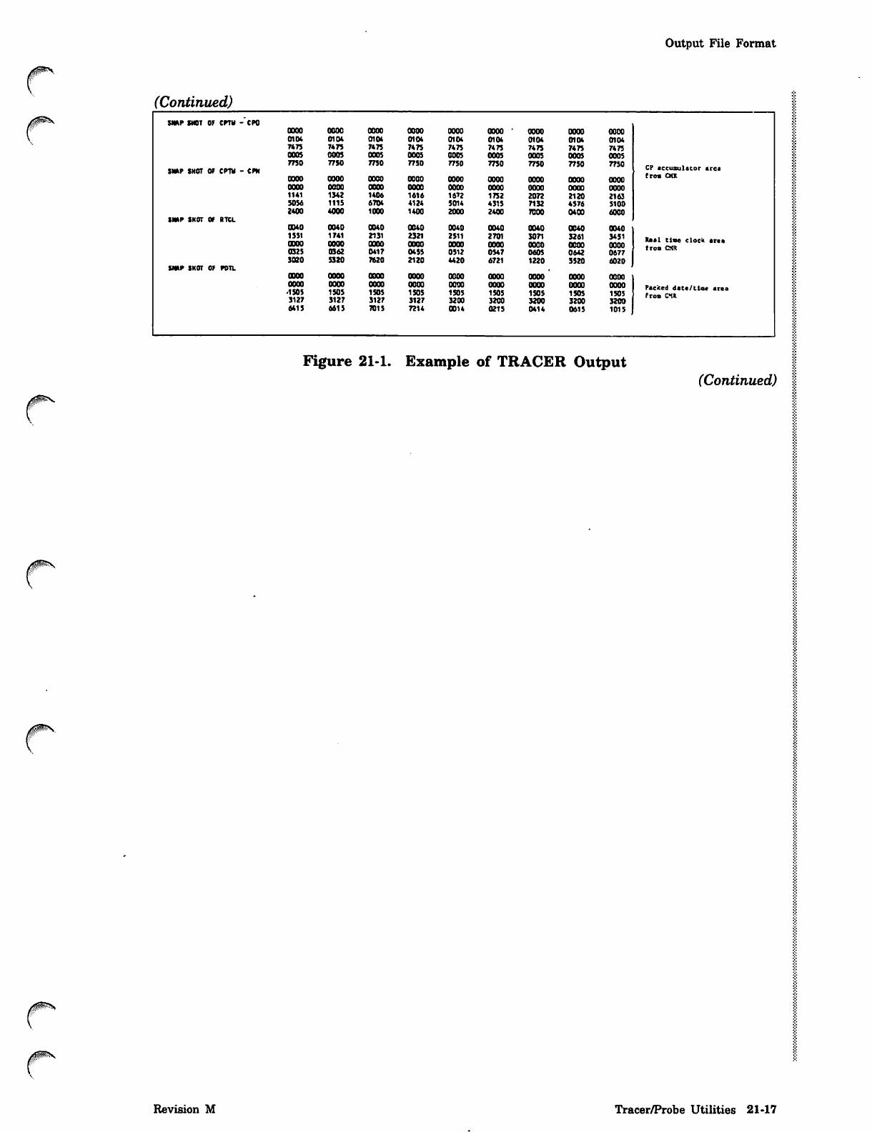
©The ssspllog frequency for snapshot loop Items Is specified by the FV persaecer of the ICPD command.
Figure 21-1. Example of TRACER Output
(Continued)
0IKS.
Revision M Tracer/Probe Utilities 21-15
Output File Format
(Continued)
/xtzm§s$\
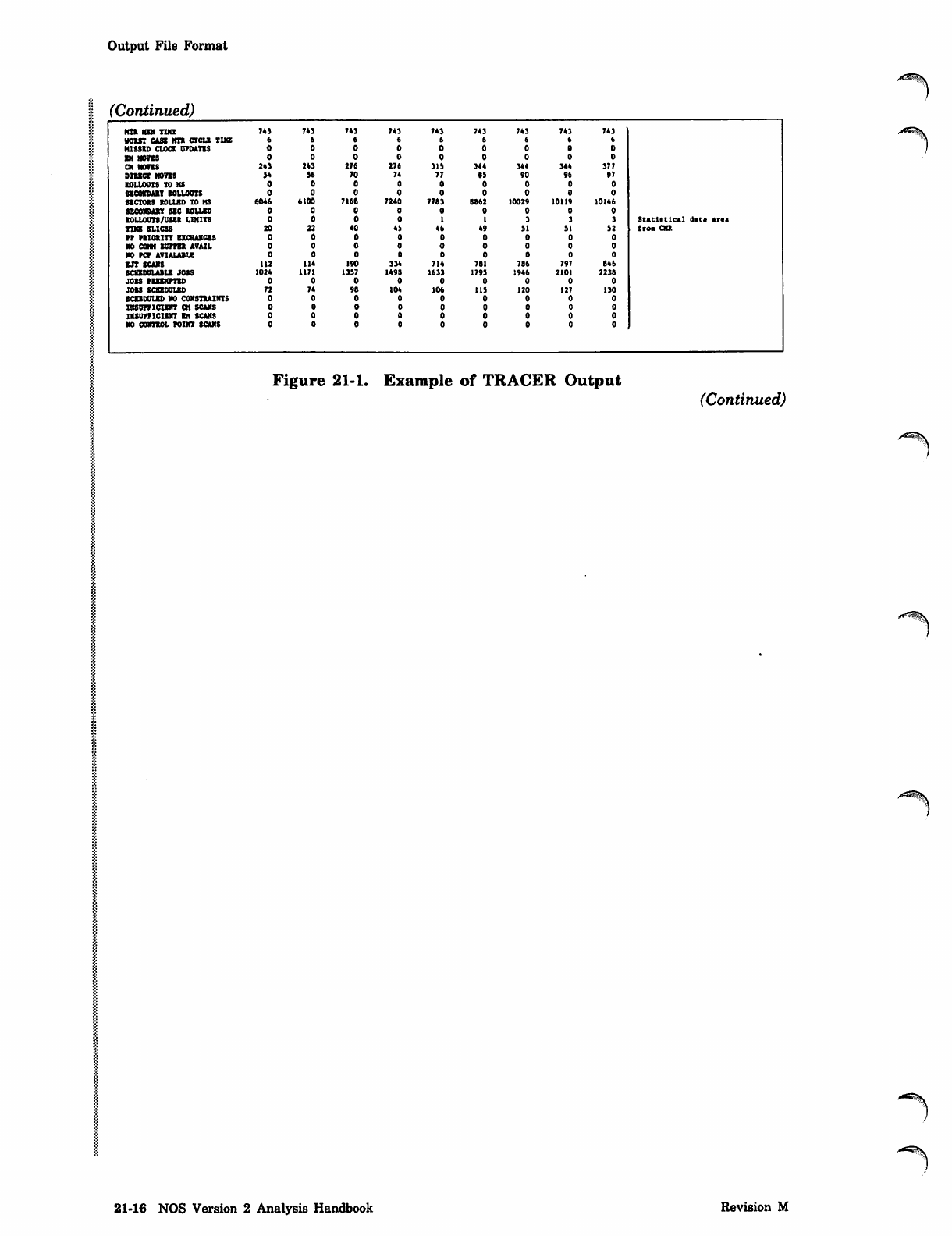
KIR HEN TUB 743 743 743 743 743 743 743 743 743
WORST CASE MTR CXCLR TIKE
MISSED CLOCK UPDATES
EN MOVES
CM MOVES 243 243 276 276 315 344 344 344 377
DIRECT MOVES 54 56 70 74 77 85 SO 96 97
ROLLOUTS TO MS
SECOVDABT ROLLOUTS
SECTORS ROLLED TD HS 6046 6100 7168 7240 7763 B862 10029 10119 10146
SECONDARY SEC ROLLED
ROLLOUTS/USER LIMITS St a t i s t i c al d st * s r « a
TIME SLICES 20 22 40 43 46 49 51 51 52 from CKR
PP PRIORITY EXCHANGES
no cam kipper avail
NO PCP AVIALABU
EJT SCANS 112 114 190 334 714 761 786 797 646
SCaSBULABLS JOSS 1024 1171 1357 149S 1633 1793 1946 2101 2236
JOBS PREEMPTED
JOBS SCEXOOUBD 72 74 98 104 106 115 120 127 130
BCEXOUIED NO CONSTRAINTS
INSUFFICIENT CH SCANS
UUOmCISRT EH SCANS
NO CONTROL POINT SCANS
Figure 21-1. Example of TRACER Output (Continued)
21-16 NOS Version 2 Analysis Handbook Revision M
Output File Format
(Continued)
SNAP SNOT OF CPTV -CPO
OOOO OOOO OOOO OOOO oooo oooo - OOOO OOOO OOOO
0104 0104 0104 0104 0104 0104 0104 0104 0104
7*75 7475 7475 7475 7475 7475 7475 7*75 7475
0005 0005 0005 0005 0005 0005 0005 0005 0005
7750 7750 7750 7750 7750 7750 7750 7750 7750
SNAP SHOT OF CPTV - CPN CP sccusulstor aret
OOOO OOOO OOOO OOOO OOOO OOOO OOOO OOOO OOOO from OCX
OOOO OOOO 0003 oooo oooo OOOO OOOO oooo OOOO
11 4 1 1342 1406 1616 1672 1752 2072 2120 2163
5056 1115 6704 4124 5014 4315 7132 4576 5100
2400 4000 1000 1400 2000 2400 7000 0400 6000
SNAP SNOT OF RTCL
0340 0040 0040 0040 0040 0040 0040 0040 0040
1551
0300
1741
OOOO
2131
OOOO
2321
OOOO
2511
OOOO
2701
OOOO
son
oooo 3261
OOOO
3451
OOOO Real time clock area
from CMR
0925 0362 0417 0455 0512 0547 0605 0642 0677
3020 5320 7620 2120 4420 6721 1220 3520 6020
SNAP SNOT OF POTL
OBOO OOOO OOOO OOOO OOOO OOOO OOOO OOOO OOOO
OOOO oooo OOOO oooo OOOO OOOO OOOO OOOO oooo Packed date/time area
-1S05 1505 1505 1505 1505 1505 1505 1505 1505 from CIR
3127 3127 3127 3127 3200 3200 3200 3200 3200
6415 6615 7015 7214 0014 0215 0414 0615 1015
Figure 21-1. Example of TRACER Output
(Continued)
r
r
r
Revision M Tracer/Probe Utilities 21-17
Output File Format
(Continued)
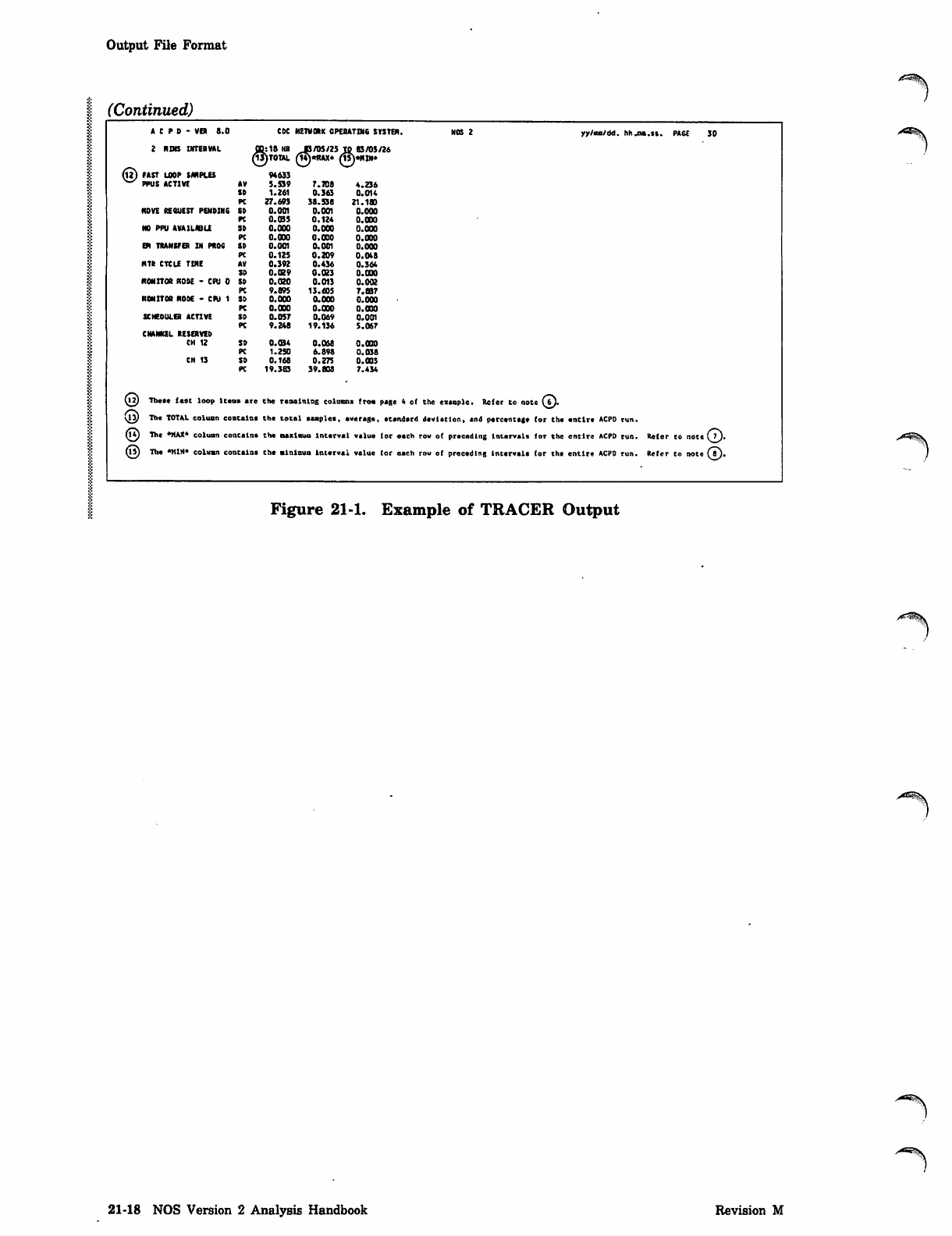
A C P D - VER 8.0 CDC N En O R K CP ER AT IN 6 SY ST EM . NO S 2 yy/ns/dd. hh.ma.st. PA6E 30
2 NOB INTERVAL 3:18 KR JB/05/25 TO 83/05/26
e
3)T0TAL T?)«1tAX* TSjeMIN*
(tt) FAST LOOP SAMPLES
^ PPUS ACTIVE 94633
AV 5.S39 7.708 4.236
SD 1.261 0.363 0.014
PC 27.693 38.538 21.180
HOVE REQUEST PENDIN6 SD 0.001 0.001 0.000
PC O.CBS 0.124 O.OOO
NO PPU AVAILABLE SD 0.000 0.000 O.OOO
PC 0.000 0.030 0.030
GN TRANSFER IN PROC SD 0.001 0.001 0.000
PC 0. 12s 0 . 2 0 9 0.048
HTR CTCLE TIME AV 0.392 0.436 0.364
SD 0.029 0.023 0.030
MONITOR NODE - CPU 0 SD 0.020 0.013 0.002
PC 9.095 13.605 7.S37
MONITOR NODE - CPU 1 SD 0.003 0.000 0.000
PC 0.000 0.000 0.000
SCHEDULER ACTIVE SD 0.057 0.069 0.001
PC 9.248 19.136 5.067
CHANNEL RESERVED
CH 12 SD 0.034 0.068 0.030
PC 1.250 6.898 0.038
CH 13 SD 0.168 0.275 0.003
PC 19.383 39.808 7.434
O2) These fast loop Items are the regaining columns from page 4 of the eutopic. Refer to note (bj.
\ly The TOTAL column contains the total samples, average, etandsrd devistlon, end percentage for the entire ACPD run.
Q£) The *MAX* column contains the Bsxlnuo lntsrval value for each row of preceding intervals for the entire ACPD run. Refer to note CO-
n?) The •KIN* column contains the minlaum Interval value (or oaeh row of preceding Intervals for the entire ACPD run. Refer to note (fl).
Figure 21-1. Example of TRACER Output
21-18 NOS Version 2 Analysis Handbook Revision M
Summary File Format
0ms
Summary FUe Format
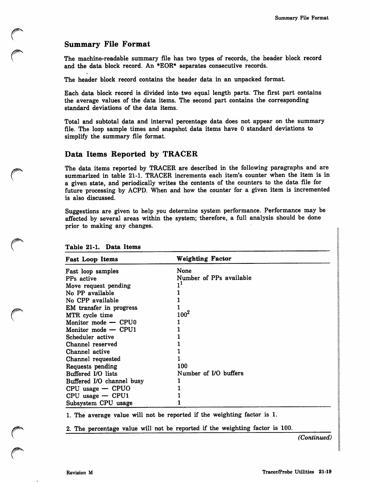
The machine-readable summary file has two types of records, the header block record
and the data block record. An *EOR* separates consecutive records.
The header block record contains the header data in an unpacked format.
Each data block record is divided into two equal length parts. The first part contains
the average values of the data items. The second part contains the corresponding
standard deviations of the data items.
Total and subtotal data and interval percentage data does not appear on the summary
file. The loop sample times and snapshot data items have 0 standard deviations to
simplify the summary file format.
Data Items Reported by TRACER
The data items reported by TRACER are described in the following paragraphs and are
summarized in table 21-1. TRACER increments each item's counter when the item is in
a given state, and periodically writes the contents of the counters to the data file for
future processing by ACPD. When and how the counter for a given item is incremented
is also discussed.
Suggestions are given to help you determine system performance. Performance may be
affected by several areas within the system; therefore, a full analysis should be done
prior to making any changes.
Table 21-1. Data Items
Fast Loop Items
Fast loop samples
PPs active
Move request pending
No PP available
No CPP available
EM transfer in progress
MTR cycle time
Monitor mode — CPUO
Monitor mode — CPU1
Scheduler active
Channel reserved
Channel active
Channel requested
Requests pending
Buffered I/O lists
Buffered I/O channel busy
CPU usage — CPUO
CPU usage — CPU1
Subsystem CPU usage
Weighting Factor
None
Number of PPs available
l
00'
00
Number of I/O buffers
1. The average value will not be reported if the weighting factor is 1.
2. The percentage value will not be reported if the weighting factor is 100.
(Continued)
Revision M Tracer/Probe Utilities 21-19
Data Items Reported by TRACER
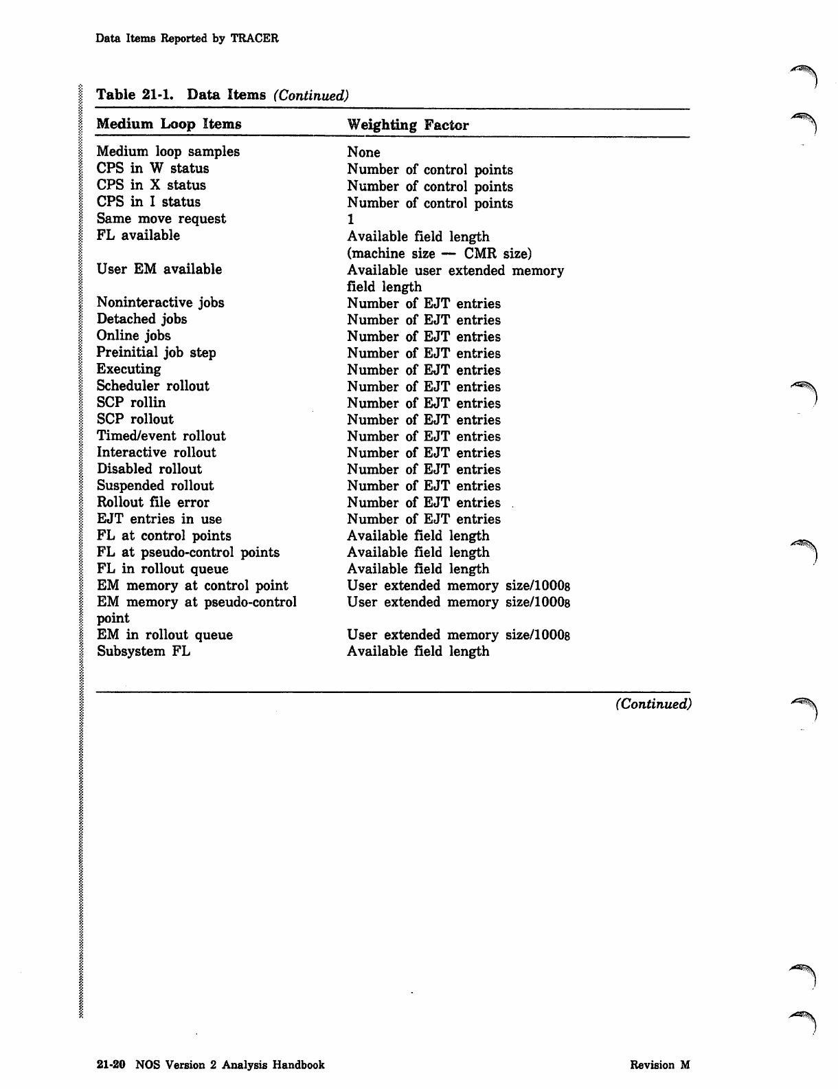
Table 21-1. Data Items (Continued)
Medium Loop Items
Medium loop samples
CPS in W status
CPS in X status
CPS in I status
Same move request
FL available
User EM available
Noninteractive jobs
Detached jobs
Online jobs
Preinitial job step
Executing
Scheduler rollout
SCP rollin
SCP rollout
Timed/event rollout
Interactive rollout
Disabled rollout
Suspended rollout
Rollout file error
EJT entries in use
FL at control points
FL at pseudo-control points
FL in rollout queue
EM memory at control point
EM memory at pseudo-control
point
EM in rollout queue
Subsystem FL
Weighting Factor
None
Number of control points
Number of control points
Number of control points
1
Available field length
(machine size — CMR size)
Available user extended memory
field length
Number of EJT entries
Number of EJT entries
Number of EJT entries
Number of EJT entries
Number of EJT entries
Number of EJT entries
Number of EJT entries
Number of EJT entries
Number of EJT entries
Number of EJT entries
Number of EJT entries
Number of EJT entries
Number of EJT entries
Number of EJT entries
Available field length
Available field length
Available field length
User extended memory size/10008
User extended memory size/10008
User extended memory size/10008
Available field length
(Continued)
21-20 NOS Version 2 Analysis Handbook Revision M
Data Items Reported by TRACER
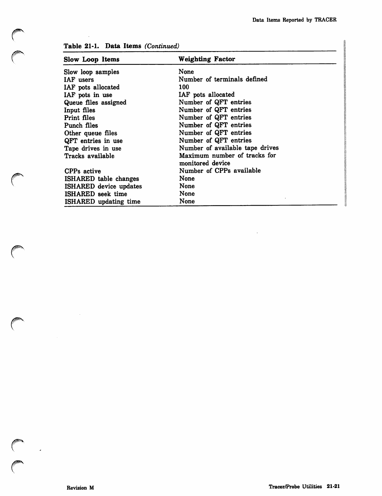
Table 21-1. Data Items (Continued)
Slow Loop Items
Slow loop samples
IAF users
IAF pots allocated
IAF pots in use
Queue files assigned
Input files
Print files
Punch files
Other queue files
QFT entries in use
Tape drives in use
Tracks available
CPPs active
ISHARED table changes
ISHARED device updates
ISHARED seek time
ISHARED updating time
Weighting Factor
None
Number of terminals defined
100
IAF pots allocated
Number of QFT entries
Number of QFT entries
Number of QFT entries
Number of QFT entries
Number of QFT entries
Number of QFT entries
Number of available tape drives
Maximum number of tracks for
monitored device
Number of CPPs available
None
None
None
None
Revision M Tracer/Probe Utilities 21-21
Fast Loop Items
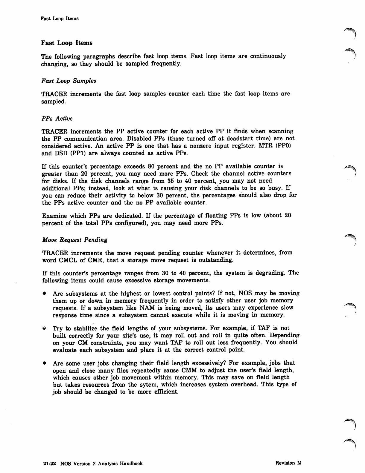
Fast Loop Items
The following paragraphs describe fast loop items. Fast loop items are continuously
changing, so they should be sampled frequently.
Fast Loop Samples
TRACER increments the fast loop samples counter each time the fast loop items are
sampled.
PPs Active
TRACER increments the PP active counter for each active PP it finds when scanning
the PP communication area. Disabled PPs (those turned off at deadstart time) are not
considered active. An active PP is one that has a nonzero input register. MTR (PPO)
and DSD (PPI) are always counted as active PPs.
If this counter's percentage exceeds 80 percent and the no PP available counter is
greater than 20 percent, you may need more PPs. Check the channel active counters
for disks. If the disk channels range from 35 to 40 percent, you may not need
additional PPs; instead, look at what is causing your disk channels to be so busy. If
you can reduce their activity to below 30 percent, the percentages should also drop for
the PPs active counter and the no PP available counter.
Examine which PPs are dedicated. If the percentage of floating PPs is low (about 20
percent of the total PPs configured), you may need more PPs.
Move Request Pending ^^)
TRACER increments the move request pending counter whenever it determines, from
word CMCL of CMR, that a storage move request is outstanding.
If this counter's percentage ranges from 30 to 40 percent, the system is degrading. The
following items could cause excessive storage movements.
• Are subsystems at the highest or lowest control points? If not, NOS may be moving
them up or down in memory frequently in order to satisfy other user job memory
requests. If a subsystem like NAM is being moved, its users may experience slow
response time since a subsystem cannot execute while it is moving in memory.
• Try to stabilize the field lengths of your subsystems. For example, if TAF is not
built correctly for your site's use, it may roll out and roll in quite often. Depending
on your CM constraints, you may want TAF to roll out less frequently. You should
evaluate each subsystem and place it at the correct control point.
• Are some user jobs changing their field length excessively? For example, jobs that
open and close many files repeatedly cause CMM to adjust the user's field length,
which causes other job movement within memory. This may save on field length
but takes resources from the sytem, which increases system overhead. This type of
job should be changed to be more efficient.
21-22 NOS Version 2 Analysis Handbook Revision M
yims
0m*,
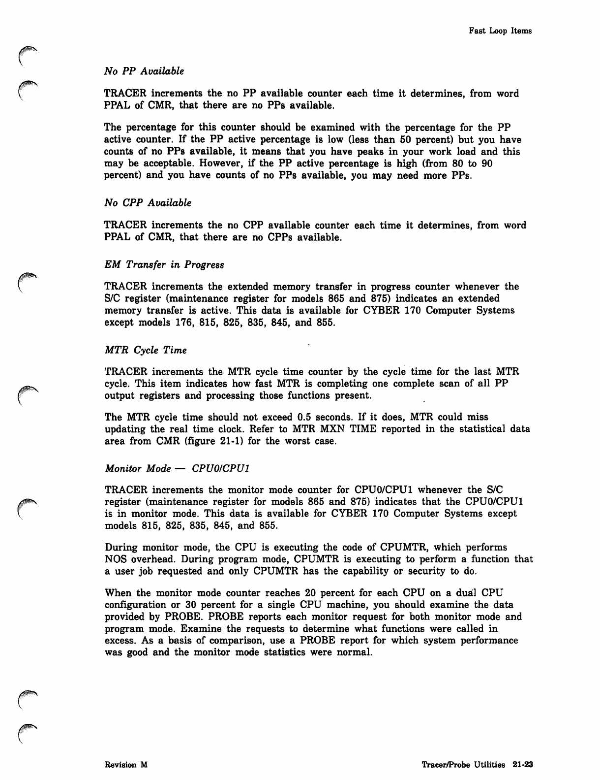
Fast Loop Items
No PP Available
TRACER increments the no PP available counter each time it determines, from word
PPAL of CMR, that there are no PPs available.
The percentage for this counter should be examined with the percentage for the PP
active counter. If the PP active percentage is low (less than 50 percent) but you have
counts of no PPs available, it means that you have peaks in your work load and this
may be acceptable. However, if the PP active percentage is high (from 80 to 90
percent) and you have counts of no PPs available, you may need more PPs.
No CPP Available
TRACER increments the no CPP available counter each time it determines, from word
PPAL of CMR, that there are no CPPs available.
EM Transfer in Progress
TRACER increments the extended memory transfer in progress counter whenever the
S/C register (maintenance register for models 865 and 875) indicates an extended
memory transfer is active. This data is available for CYBER 170 Computer Systems
except models 176, 815, 825, 835, 845, and 855.
MTR Cycle Time
TRACER increments the MTR cycle time counter by the cycle time for the last MTR
cycle. This item indicates how fast MTR is completing one complete scan of all PP
output registers and processing those functions present.
The MTR cycle time should not exceed 0.5 seconds. If it does, MTR could miss
updating the real time clock. Refer to MTR MXN TIME reported in the statistical data
area from CMR (figure 21-1) for the worst case.
Monitor Mode — CPU0ICPU1
TRACER increments the monitor mode counter for CPU0/CPU1 whenever the S/C
register (maintenance register for models 865 and 875) indicates that the CPU0/CPU1
is in monitor mode. This data is available for CYBER 170 Computer Systems except
models 815, 825, 835, 845, and 855.
During monitor mode, the CPU is executing the code of CPUMTR, which performs
NOS overhead. During program mode, CPUMTR is executing to perform a function that
a user job requested and only CPUMTR has the capability or security to do.
When the monitor mode counter reaches 20 percent for each CPU on a dual CPU
configuration or 30 percent for a single CPU machine, you should examine the data
provided by PROBE. PROBE reports each monitor request for both monitor mode and
program mode. Examine the requests to determine what functions were called in
excess. As a basis of comparison, use a PROBE report for which system performance
was good and the monitor mode statistics were normal.
Revision M Tracer/Probe Utilities 21-23
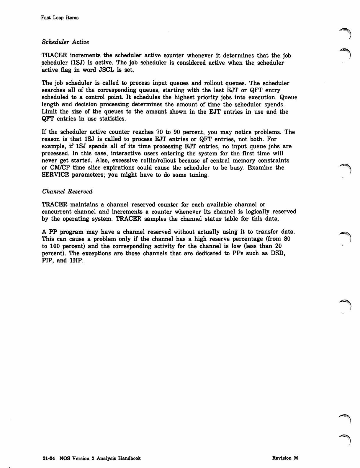
Fast Loop Items
Scheduler Active
TRACER increments the scheduler active counter whenever it determines that the job
scheduler (1SJ) is active. The job scheduler is considered active when the scheduler
active flag in word JSCL is set.
The job scheduler is called to process input queues and rollout queues. The scheduler
searches all of the corresponding queues, starting with the last EJT or QFT entry
scheduled to a control point. It schedules the highest priority jobs into execution. Queue
length and decision processing determines the amount of time the scheduler spends.
Limit the size of the queues to the amount shown in the EJT entries in use and the
QFT entries in use statistics.
If the scheduler active counter reaches 70 to 90 percent, you may notice problems. The
reason is that 1SJ is called to process EJT entries or QFT entries, not both. For
example, if 1SJ spends all of its time processing EJT entries, no input queue jobs are
processed. In this case, interactive users entering the system for the first time will
never get started. Also, excessive rollin/rollout because of central memory constraints
or CM/CP time slice expirations could cause the scheduler to be busy. Examine the
SERVICE parameters; you might have to do some tuning.
Channel Reserved
TRACER maintains a channel reserved counter for each available channel or
concurrent channel and increments a counter whenever its channel is logically reserved
by the operating system. TRACER samples the channel status table for this data.
A PP program may have a channel reserved without actually using it to transfer data.
This can cause a problem only if the channel has a high reserve percentage (from 80
to 100 percent) and the corresponding activity for the channel is low (less than 20
percent). The exceptions are those channels that are dedicated to PPs such as DSD,
PIP, and 1HP.
y*^fe\
21-24 NOS Version 2 Analysis Handbook Revision M
00&?\
Fast Loop Items
Channel Active
TRACER maintains a channel active counter for each available channel and increments
a counter whenever it detects that the channel is not inactive, as determined by an
UM PP instruction.
System performance is affected most by disk channel activity. A percentage of from 10
to 30 percent is considered normal. When this percentage reaches 35 to 40 percent,
your system may experience performance degradation. High channel activity could be
caused by the following factors. If you can scale down these problems, you may
decrease channel activity and improve system performance; otherwise, you may need
more disk controllers.
• Do all the disk channels show similar activity levels? If not, examine the attributes
you have described for each disk unit. For example, what units contain permanent
files, rollout files, a copy of the system, and temporary files? You may have to
redistribute the work load by changing attributes. Determine which files are busy
and the devices on which they reside using the PFCAT utility. You may find that
altering device masks and/or moving files will lower the channel activity. You are
looking for an even percentage of work performed by each of the disk channels.
The system selects file residency based on several factors. If the file is a permanent
file, the system uses the device masks you have set for your family. If it is a
temporary file or rollout file, the system looks at the attributes set for each device
and selects the best candidate based on the following.
- First, the system looks at the number of tracks available on each potential
device. If any of the devices have fewer tracks available than the low space
threshold set by the THRESHOLD command, those devices will no longer be
candidates for selection unless all of the other potential devices are also below
their threshold levels.
- Second, the system picks (from the remaining candidates) the device with the
least activity.
® Are there an excessive number of rollouts? User jobs may be reaching the CM or
CP time slice limits. Check your SERVICE parameters and examine the number of
time slices reported in the statistical data area from CMR. The system may be
rolling jobs in and out of the control points if your SERVICE limits are too small.
By adjusting the limits, you should improve system performance.
© Are large user jobs or subsystems rolling in or out? This can be determined by
watching the DSD rollout status display (R). One large job can cause problems if it
uses too many resources. Redesigning or rescheduling the job may help.
• Examine the PROBE utility output. PROBE reports the PP programs that were
loaded (program name, residency, and number of loads). Any program that is
loading more than once per second, should be made central memory resident. If you
are short of central memory, place these programs in extended memory.
Revision M Tracer/Probe Utilities 21-25
Fast Loop Items
Channel Requested
TRACER maintains a channel requested counter for each available channel or
concurrent channel and increments a counter whenever there is an outstanding request
for that channel. TRACER uses the channel status table to determine the channel
requested status.
This counter tells you how often PP programs have requested a channel but were
unable to reserve it because another PP program had it reserved. A normal count is
from 20 to 50 percent. The exceptions are those channels that are dedicated to PPs
such as DSD, PIP, and 1HP.
This can be used for debugging purposes when developong your own PP programs that
require channels. Be sure that you follow the rules governing channel dialog.
Requests Pending
TRACER maintains a request pending counter for each mass storage device available
and increments a counter by the number of outstanding requests on that device when
the sampling occurs. The MST provides this information.
Ensure that the number of requests pending is evenly distributed between all units. If
not, you may have to redistribute files (permanent, system, temporary, and rollout
files) for the devices to obtain a more even distribution. Adding more disk units to a
configuration will also aid in reducing the number of requests outstanding.
Buffered IIO Lists
TRACER maintains a counter for each type of buffered I/O buffer list (Empty, Data
Written, Read, Write). The number of buffers assigned to each list is incremented
based on the buffered I/O data tables.
An average of 25 percent of the buffers on the Empty and Data Written lists is
normal. The Write list should contain from 2 to 3 percent of the buffers, but a higher
percentage is acceptable. The Read list is normal at from 65 to 75 percent. If there
seems to be a shortage of Empty and Data Written buffers, you can add more extended
memory for I/O buffer space.
Buffered IIO Channel Busy
TRACER maintains a PP driver busy counter for each buffered I/O channel and
increments a counter whenever a data transfer associated with that channel is in
progress. For 885-4x disks, the data transfer occurs through the low-speed port to ESM
rather than the channel; only control and status information transfers over the channel.
TRACER uses the buffered I/O channel control table to determine the PP driver busy
status.
The normal percentage is from 15 to 20 percent for a model 760 with two channels.
This percentage may be higher for machines with slower CPUs.
/£*3SS^y
j^Sfe.
21-26 NOS Version 2 Analysis Handbook Revision M
00ms.
JffitW$*s,
Fast Loop Items
CPU Usage
TRACER maintains a set of CPU usage counters for each CPU. There is a counter for
each type of CPU use.
Counter CPU Use
IDLE CPU is not currently being used.
SYSTEM CPU is being used by CPUMTR.
SUB-SYS CPU is being used by a subsystem.
SYS ORG CPU is being used by a system origin job (subsystems are not
considered system origin).
USER CPU is being used by a user program.
Each time the CPU status is sampled (in words CPAL and CPAL+1 in CMR),
TRACER increments one of the CPU usage counters. It determines which counter to
update by investigating the control point area to which the CPU is assigned.
Tune your system to get the most CPU usage for your users. Following are suggestions
on how to do this.
• If you run a mixture of jobs, such as interactive and batch jobs, set the limit of
executing batch jobs to a number that minimally impacts interactive users with
respect to central memory and control points. You may have to assign batch jobs a
higher queue priority so they essentially will be locked into the control points.
Since interactive jobs tend to use the CPU for short durations, the batch jobs will
be there using up whatever CPU time is left from the interactive jobs.
• On machines with big memories, it is usually advantageous to assign most of the
memory to the users instead of using UEM as a rollout device. This helps in two
ways: 1) rolling jobs to disk usually takes less CPU overhead than rolling jobs to
UEM; 2) with more memory for the users, NOS performs less storage moves.
However, if you are rolling jobs to 895 disks and your system is CPU-saturated,
you may want to rollout jobs to UEM and use the ENABLE.DDP ROLLOUT PATH
entry in the IPRDECK. This will make rollout processing slower but should reduce
system CPU usage.
• If you run site-developed subsystems, examine the possibility of performing more of
the work as disk activity rather than manipulating the data in central memory.
Subsystem CPU Usage
Subsystem CPU usage is a further breakdown of subsystems of the SUB-SYS CPU
usage data. TRACER maintains a CPU usage counter for every subsystem. Whenever
the SUB-SYS CPU usage counter is incremented, TRACER also increments the
appropriate subsystem CPU usage counter.
Revision M Tracer/Probe Utilities 21-27
Medium Loop Items
Medium Loop Items
The following paragraphs describe medium loop items. j
Medium Loop Samples
TRACER increments the medium loop samples counter each time the medium loop
items are sampled.
CPS in W Status
TRACER increments the control points in waiting (W) status counter whenever a
control point is found in W status (determined by STSW word of control point area).
TRACER scans all control points during each medium loop cycle.
CPS in X Status
TRACER increments the control points in periodic or automatic recall (X) status
counter whenever it finds a control point in X status (determined by STSW word of
control point area). TRACER scans all control points during each medium loop cycle.
CPS in I Status
TRACER increments the control points in automatic recall (I) status counter whenever
a control point is found in I status (determined by STSW word of control point area).
TRACER scans all control points during each medium loop cycle.
Same Move Request
TRACER increments the same move request counter every time the move request
pending for the current medium loop cycle is the same as the previous medium loop
cycle. Word CMCL of CMR is used to determine this status.
Use this counter to determine if NOS is having trouble moving jobs ih central memory.
A value of from 5 to 10 percent is not unreasonable. A higher percentage indicates
that you probably are short of memory. Examine the FL available counter.
FL Available
TRACER increments the FL available counter by the amount of available FL during
the current medium loop cycle. Word ACML of CMR determines the available FL.
Compare this counter with the average FL in the rollout queue (FL in the rollout
queue divided by the average number of jobs in the queue). On a busy system, the
average amount of FL available should be less than that required for the average job
in the rollout queue. You may need to consider any jobs that are in the rollout queue
but are not schedulable, such as NAM supervisory applications (CS, NS, and NVF). On
a system that is not heavily used, the FL available counter is of little value since
there should always be memory available.
A ^ ^ S
21-28 NOS Version 2 Analysis Handbook Revision M
0ps
0$m\
Medium Loop Items
User EM Available
TRACER increments the user extended memory available counter by the amount of
available user extended memory FL during the current medium loop cycle. Word AECL
of CMR determines the available user extended memory FL.
Compare this number to the amount of extended memory at control points and rollout
queues to determine if you have enough user extended memory.
Noninteractive Jobs
TRACER maintains a count of noninteractive jobs by monitoring the number of EJT
entries with a connection status of NICS.
Detached Jobs
TRACER maintains a count of detached interactive jobs by monitoring the number of
EJT entries with a connection status of DTCS.
Online Jobs
TRACER maintains a count of online jobs by monitoring the number of EJT entries
with a connection status of OLCS.
Preinitial Job Step
TRACER maintains a count of preinitial jobs for each service class by monitoring the
number of EJT entries with a job status of PRJS. A job is in this state after it has
been assigned to an EJT entry but before it has been assigned to a control point for
the first time.
Executing
TRACER maintains a count of executing jobs for each service class by monitoring the
number of EJT entries with a job status of EXJS.
Scheduler Rollout
TRACER maintains a count of jobs rolled out by the job scheduler for each service
class by monitoring the number of EJT entries with a job status of ROJS.
SCP Rollin
TRACER maintains a count of jobs rolled in by system control point processing for
each service class by monitoring the number of EJT entries with a job status of SIJS.
SCP Rollout
TRACER maintains a count of jobs rolled out by system control point processing for
each service class by monitoring the number of EJT entries with a job status of SOJS.
Revision M Tracer/Probe Utilities 21-29
Medium Loop Items
TimedlEvent Rollout
TRACER maintains a count of jobs in a timed/event rollout queue for each service
class by monitoring the number of EJT entries with a job status of TOJS.
Interactive Rollout
TRACER maintains a count of jobs rolled out by interactive input/output processing for
each service class by monitoring the number of EJT entries with a job status of IOJS.
Disabled Rollout
TRACER maintains a count of disabled jobs rolled out for each service class by
monitoring the number of EJT entries with a job status of DOJS.
Suspended Rollout
TRACER maintains a count of suspended jobs rolled out for each service class by /*^\
monitoring the number of EJT entries with a job status of SUJS.
Rollout File Error
TRACER maintains a count of jobs with rollout file errors for each service class by
monitoring the number of EJT entries with a job status of ERJS.
EJT Entries in Use
TRACER-maintains a count of the number of EJT entries in use for all jobs during the
specified time interval. Each EJT entry is four central memory words long. If you are
short of memory, you can gain some memory by decreasing the number of EJT entries.
FL at Control Points
TRACER maintains an FL at control point counter for each service class. When an
active control point is found, the service class is determined and the appropriate
counter is incremented by the amount of FL assigned to that control point (determined ^^
by FLSW of control point area). TRACER scans all control points during the medium J
loop cycle.
Use this count to determine which service class of jobs is using the most memory. For
example, if you have poor interactive job response and notice that the batch service
class is using the most memory, it may help to restrict batch jobs to a smaller central
memory time slice using the CM parameter of the SERVICE entry in the IPRDECK.
21-30 NOS Version 2 Analysis Handbook Revision M
Medium Loop Items
0^s.
r
FL at Pseudo-control Points
TRACER maintains an FL at pseudo-control point counter for each service class. When
an active pseudo-control point is found, the service class is determined and the
appropriate counter is incremented by the amount of FL assigned to that pseudo-control
point (determined by FLSW of pseudo-control point area). TRACER scans all
pseudo-control points during the medium loop cycle.
FL in Rollout Queue
TRACER maintains an FL in rollout queue counter for each service class. When a
rollout file is found in the queue, and it is not assigned to a control point, the amount
of FL it will require (determined from the EJT) when it is rolled into a control point
is added to the appropriate counter. TRACER scans all EJT entries during the medium
loop cycle.
Use this count in conjunction with the FL available counter to determine if you have a
central memory shortage.
EM Memory at Control Points
TRACER maintains an extended memory at control point counter for each service class.
When an active control point is found, the service class is determined and the
appropriate counter is incremented by the amount of extended memory assigned to that
control point (determined by ECSW of control point area). TRACER scans all control
points during the medium loop cycle.
Use this count in conjunction with the user EM available counter and the EM in
rollout queue counter to determine if you have an extended memory shortage.
EM Memory at Pseudo-control Points
Use this count in conjunction with the user EM available counter and the EM in
rollout queue counter to determine if you have an extended memory shortage.
EM in Rollout Queue
TRACER maintains an extended memory in rollout queue counter for each service
class. When a rollout file is found in the queue, and it is not assigned to a control
point, the amount of extended memory FL it will require when rolled in (determined
from the EJT) is added to the appropriate counter. TRACER scans all EJT entries
during the medium loop cycle.
Use this count in conjunction with the user EM available counter and the EM memory
at CP counter to determine if you have an extended memory shortage.
Subsystem FL
TRACER maintains a subsystem FL counter for every possible subsystem. When a
subsystem is found at a control point, the amount of FL assigned to that subsystem is
added to the appropriate counter. TRACER scans all control points during the medium
loop cycle.
Revision M Tracer/Probe Utilities 21-31
Slow Loop Items
Slow Loop Items
The following paragraphs describe slow loop items.
Slow Loop Samples
TRACER increments the slow loop samples counter each time the slow loop items are
sampled.
IAF Users
TRACER increments the IAF users counter by the number of users connected to IAF
during the slow loop cycle. IAF must be active for this data to be collected. Word
VANL of IAF FL determines the number of users.
IAF Pots Allocated
TRACER increments the pots allocated counter by the number of pots that are
currently available for use, whether they are being used or not. Word VPAL of IAF FL
determines the number of pots allocated.
IAF Pots in Use
TRACER increments the pots in use counter by the number of pots currently assigned
to a connection. Word VPUL of IAF FL determines the number of pots in use.
Queue Files Assigned
TRACER maintains a count of the number of queued files assigned to control points by
monitoring QFT entries.
Input Files
TRACER maintains a count of the number of input files for each service class by
monitoring QFT entries.
Print Files
TRACER maintains a count of the number of print files for each service class by
monitoring QFT entries.
Punch Files
TRACER maintains a count of the number of punch files for each service class by
monitoring QFT entries.
Other Queue Files
TRACER maintains a count of the number of other queued files not assigned to control
points for each service class by monitoring QFT entries. This includes any queued file
that is not an input, print, or punch file.
21-32 NOS Version 2 Analysis Handbook Revision M
Slow Loop Items
QFT Entries in Use
TRACER maintains a count of the number of QFT entries in use for all jobs during
the specified time interval. Each QFT entry is four central memory words long. If you
are short of memory, you can gain some memory by decreasing the number of QFT
entries.
Tape Drives in Use
TRACER maintains two tape drives in use counters; one for 7-track and one for 9-track
drives. A tape drive is considered to be in use if an EST entry indicates it is logically
turned on, and it is assigned to a job. TRACER increments the appropriate counter for
each drive found in use.
Tracks Available
TRACER maintains a tracks available counter for each mass storage equipment and
adds the number of available tracks (tracks not currently assigned to a file) for a
device to the appropriate counter for each mass storage device found in the EST.
TRACER obtains this information from TDGL of the MST.
CPPs Active
TRACER increments the CPP active counter for each active CPP it finds when
scanning the PP communication area. Disabled CPPs (those turned off at deadstart
time) are not considered active. An active CPP is one that has a nonzero input
register.
ISHARED Table Changes
TRACER maintains a count of the number of monitor function calls that force a table
update in an ISHARED environment.
ISHARED Device Updates
TRACER maintains a count of the number of times the device-resident tables are
updated in an ISHARED environment.
ISHARED Seek Time
TRACER monitors the ISHARED seek time by recording the total time spent reading
the first sector during a table update sequence.
ISHARED Updating Time
TRACER monitors the ISHARED updating time by recording the total time spent
updating tables and the maximum time and minimum time to update the tables for
both single and simultaneous operations.
Revision M Tracer/Probe Utilities 21-33
Statistical Summary
Statistical Summary
The following paragraphs describe various statistics collected by TRACER.
MTR Maximum Time
TRACER reports the maximum time, in microseconds, that MTR waits for a CPU
exchange to occur after being initiated by a monitor exchange jump (MXN).
Direct Moves
Tracer reports the number of direct storage moves of central memory.
Worst Case MTR Cycle Time
TRACER reports the maximum time, in milliseconds, that it takes MTR to make a
complete cycle; processing all PP output register requests and performing its other
system functions. y*=5^
Missed Clock Updates
TRACER reports the number of times MTR was not able to update the clock.
Extended Memory Moves
TRACER reports the number of storage moves of extended memory performed by
CPUMTR.
Central Memory Moves
TRACER reports the number of storage moves of central memory performed by
CPUMTR.
Total Rollouts
TRACER reports the total number of jobs rolled out by the job rollout routine (1RO).
Secondary Rollouts
TRACER reports the number of jobs rolled out to secondary rollout devices by the job
rollout routine (1RO).
Total Sectors Rolled
TRACER reports the total number of sectors of mass storage used by the job rollout
routine (1RO) for rollouts.
21-34 NOS Version 2 Analysis Handbook Revision M
Statistical Summary
Secondary Sec Rolled
TRACER reports the number of sectors of mass storage used by the job rollout routine
(1RO) for rollouts to secondary rollout devices.
RolloutslUser Limits
TRACER reports the number of jobs rolled out due to a time limit or SRU limit
detected by the job scheduler (1SJ).
Time Slices
TRACER reports the number of jobs whose scheduling is set to the lower bound for its
service class due to an expired CPU or CM time slice.
PP Priority Exchanges
/^^ TRACER reports the number of priority exchange requests issued by PPs and CPPs. A
- priority exchange is issued after three unsuccessful attempts to perform a monitor
exchange jump (MXN).
No Comm Buffer Avail
TRACER reports the number of times CPUMTR could not use a communications buffer
because all buffers were full.
No PCP Available
TRACER reports the number of times a pseudo-control point was not available.
EJT Scans
TRACER reports the number of times the job scheduler (1SJ) scans the executing job
table (EJT) to schedule a job to a control point.
Schedulable Jobs
TRACER reports the total number of schedulable jobs. This is determined by adding
the number of schedulable jobs in EJT on each EJT scan.
Jobs Preempted
TRACER reports the number of jobs rolled out so the job scheduler (1SJ) could
schedule a higher priority job.
Jobs Scheduled
TRACER reports the number of jobs scheduled to a control point.
/^^V.
/JP^V^
Revision M Tracer/Probe Utilities 21-35
Statistical Summary
Scheduled No Constraints
TRACER reports the number of jobs scheduled with no service class, central memory,
or extended memory constraints imposed.
Insufficient CM Scans
TRACER reports the number of EJT scans for which a schedulable job was found, but
could not be scheduled due to insufficient central memory.
Insufficient EM Scans
TRACER reports the number of EJT scans for which a schedulable job was found, but
could not be scheduled due to insufficient extended memory.
No Control Point Scans
TRACER reports the number of EJT scans for which a schedulable job was found, but
could not be scheduled because all control points were busy.
-*&s
21-36 NOS Version 2 Analysis Handbook Revision M
ym*s
PROBE Utility
PROBE Utility
The PROBE utility measures the following:
• Number of times a PP or CPP routine was loaded.
• Number of CIO RA+1 requests by function number.
• Number of PP requests to CPUMTR by function number.
• Number of MTR requests to CPUMTR by function number.
• Statistical data accumulated in CMR includes items such as number of sectors
rolled, number of rollouts, and number of pseudo-rollouts.
• Input/output statistics for 885-42 and 895 Disk Storage Subsystems showing the
number of sectors transferred and control buffer tables transferred.
PROBE data gathering is selectable at deadstart time by an IPRDECK entry. SYSEDIT
resets the PROBE data tables to zeros.
The PROBE utility generates a report from the data collected by the system. PROBE
analyzes data either from system tables or from a binary file containing data from a
previous PROBE run. An IPRDECK entry ENABLE,PROBE must be specified at
deadstart time to allow the system to collect the data. (Refer to section 3, Deadstart
Decks, for more information.)
Format:
PROBE,pi,p2.
Pi
.Pn
Description
B=readfile Binary file to be read. Default is STATS.
L=outfile Report file. Default is OUTPUT.
L=0 No report is to be generated.
LO=opt Sort option for PP program load information. Default is F.
opt Description
A Sort data in alphabetic order.
F Sort data by frequency of loads.
R Sort data by location and frequency of loads.
Revision M Tracer/Probe Utilities 21-37
PROBE Utility
Pi
OP=opt
P = writefile
P=0
R
NOTE
Description
Processing option. Default is P.
opt Description
C Perform R option functions and clear system tables after they
are read.
P Generate report from binary file specified by the B parameter.
This binary file has been created by a previous PROBE run
with OP=C or OP=R specified.
R Read system tables, and write binary file and report file as
specified.
Binary file to be written. Default is STATS.
No binary file is to be written.
Rewind binary files before and after operation. Default is no rewind.
The file names must be unique. If you specify OP=C or OP=R, then you may not
specify P=0.
Figure 21-2 is an example of the PROBE output file format.
When looking at the PP program load information reported on the PROBE output,
check to see if it meets these suggested performance requirements:
• PP programs called at least once every second should be central memory resident.
• PP programs called at least once every 2 seconds are good candidates for alternate
residency using extended memory.
• PP programs called every 3 seconds or less should be disk resident.
You can change a PP program's residency using the SYSEDIT command (refer to
section 19, SYSEDIT).
21-38 NOS Version 2 Analysis Handbook Revision M
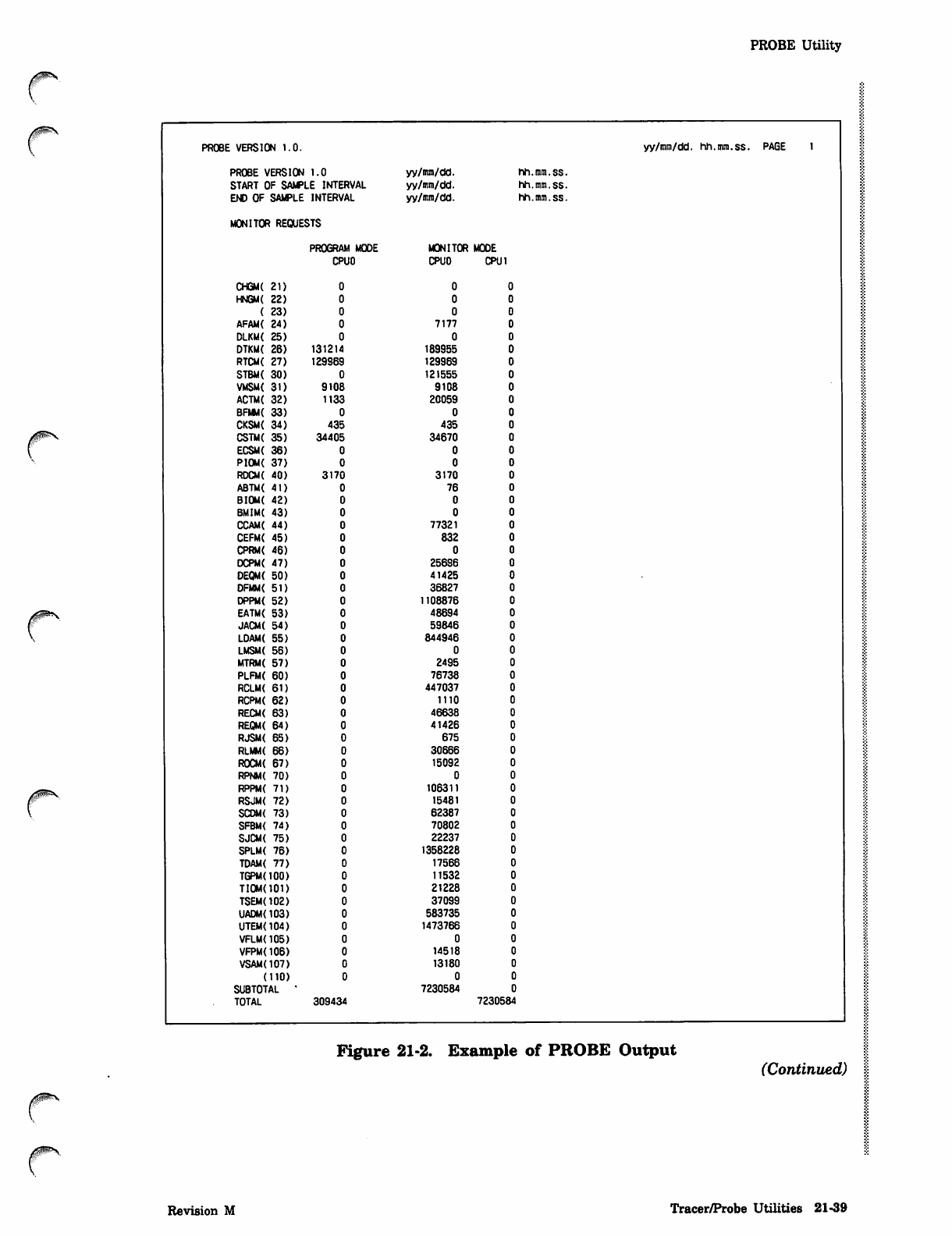
PROBE Utility
r
0*^S
PROBE VERSION 1.0. yy/mm/dd. hh.mm.ss. PAGE 1
PROBE VERSION 1.0 yy/mm/dd. hh.mm.ss.
START OF SAMPLE INTERVAL yy/mm/dd. hh.mm.ss.
END OF SAMPLE INTERVAL yy/mm/dd. hh.mm.ss.
MONITOR REQUESTS
PROGRAM MODE MONITOR MODE
CPUO C P U O C PU 1
CHGM( 21)
HNGM( 22)
( 23)
AFAM( 24) 7177
DLKM{ 25)
DTKM{ 26) 131214 189955
RTCM( 27) 129S69 129969
STBM( 30) 121555
VMSM( 31) 9108 9108
ACTM( 32) 1133 20059
BFMM( 33)
CKSM( 34) 435 435
CSTM( 35) 34405 34670
ECSM( 36)
PIOM{ 37)
RDCM{ 40) 3170 3170
ABTM< 41) 76
BIOM( 42)
BMIM( 43)
CCAM( 44) 77321
CEFM( 45) 832
CPRM( 46)
DCPM( 47) 25696
DEQM( 50) 41425
OFMM{ 51) 36827
DPPM( 52) 1108876
EATM( 53) 48694
JACM( 54) 59846
LDAM( 55) 844946
LMSM( 56)
MTRM( 57) 2495
PLFM( 60) 76738
RCLM( 61) 447037
RCPM( 62) 1110
RECM( 63) 46638
REQM{ 64) 41426
RJSM{ 65) 675
RLMM( 66) 30666
ROCM( 67) 15092
0
106311
15481
62387
70802
22237
1358228
17566
11532
21228
37099
583735
1473766
0
14518
13180
0
7230584
309434 7230584
r
Figure 21-2. Example of PROBE Output (Continued)
Revision M Tracer/Probe Utilities 21-39
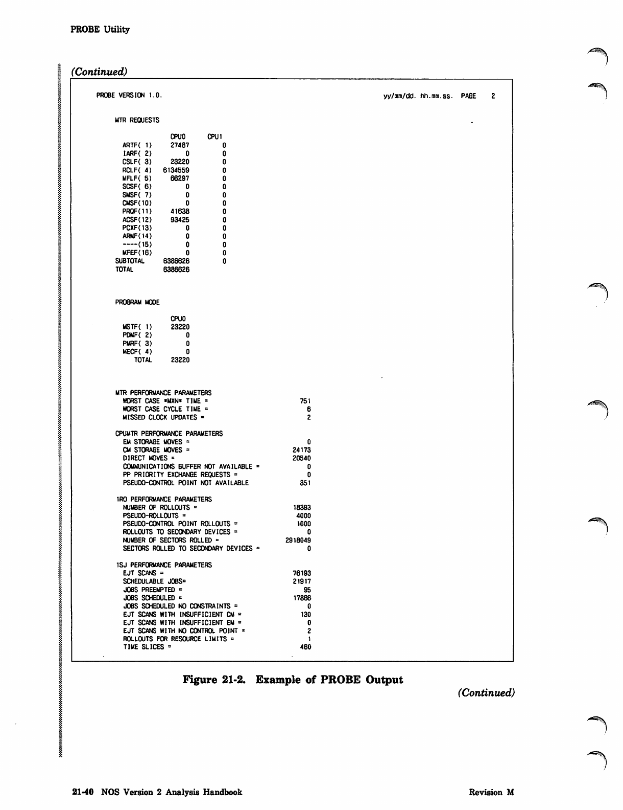
PROBE Utility
(Continued)
PROBE VERSION 1.0. yy/mm/dd. hh.mm.ss. PAGE 2
MTR REQUESTS
CPU O CPU 1
ARTF{ 1) 27487
I A R F { 2 ) 0
CSLF< 3) 23220
RCLF{ 4) 6134559
MFLF( 5) 66297
S C S F ( 6 ) 0
S M S F < 7 ) 0
CMSF<10) 0
PRQF(11) 41638
ACSF(12) 9 3 425
PCXF(13) 0
ARMF(14) 0
( 1 5 ) 0
MFEF(16) 0
SUBTOTAL 6386626
TOTAL 6386626
PROGRAM MODE
CPUO
MST F{ 1) 2 3220
P D M F ( 2 ) 0
P M R F { 3 ) 0
M E C F ( 4 ) 0
TOTAL 23220
MTR PERFORMANCE PARAMETERS
WORST CASE «MXN» TIME = 751
WORST CASE CYCLE TIME =
MISSED CLOCK UPDATES *
CPUMTR PERFORMANCE PARAMETERS
EM STORAGE MOVES =
CM STORAGE MOVES = 24173
DIRECT MOVES = 20540
COMMUNICATIONS BUFFER NOT AVAILABLE =
PP PRIORITY EXCHANGE REQUESTS =
PSEUDO-CONTROL POINT NOT AVAILABLE 351
1RO PERFORMANCE PARAMETERS
NUMBER OF ROLLOUTS = 18393
PSEUDO-ROLLOUTS * 4000
PSEUDO-CONTROL POINT ROLLOUTS = 1000
ROLLOUTS TO SECONDARY DEVICES =
NUMBER OF SECTORS ROLLED « 2918049
SECTORS ROLLED TO SECONDARY DEVICES =
1SJ PERFORMANCE PARAMETERS
EJT SCANS = 76193
SCHEDULABLE JOBS* 21917
JOBS PREEMPTED = 95
JOBS SCHEDULED = 17866
JOBS SCHEDULED NO CONSTRAINTS =
EJT SCANS WITH INSUFFICIENT CM = 130
EJT SCANS WITH INSUFFICIENT EM =
EJT SCANS WITH NO CONTROL POINT =
ROLLOUTS FOR RESOURCE LIMITS =
TIME SLICES = 460
Figure 21-2. Example of PROBE Output
(Continued)
^\
21-40 NOS Version 2 Analysis Handbook Revision M
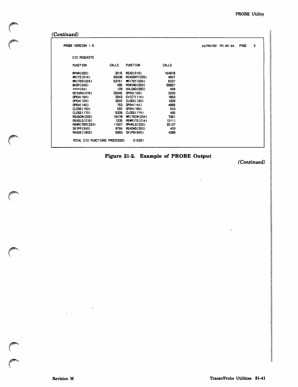
PROBE Utility
(Continued)
PROBE VERSION 1.0. yy/mm/tid. hh.mm.ss. PAGE 3
CIO REQUESTS
FUNCTION CALLS FUNCTION CALLS
RPHR(OOO) 3015 READ(OIO) 154978
WRITE(014) 83438 READSKP(020) 4907
WRITER(024) 53751 WRITEF(034) 5237
BKSP(040) 465 REWIND(050) 55857
««*(54) 128 UNLOAD(060) 459
RETURNC070) 30345 OPENOOO) 2200
OPEN(104) 2643 EVICT(114) 1653
OPEN<120) 2602 CLOSE(130) 1356
OPEN(140) 753 0PENO44) 4885
CLOSE(150) 582 0PEN(160) 543
CL0SE(170) 5339 CLOSEt174) 465
READCW(200) 15476 WRITECW(204) 7361
READLS(210) 1235 REWRITE(214) 13111
REWRITER(224) 11907 RPHRLS(230) 25137
SKIPF(240) 9784 READNS(250) 400
READEI(600) 5893 SKIPB(640) 4386
TOTAL CIO FUNCTIONS PROCESSED 510291
Figure 21-2. Example of PROBE Output (Continued)
Revision M Tracer/Probe Utilities 21-41
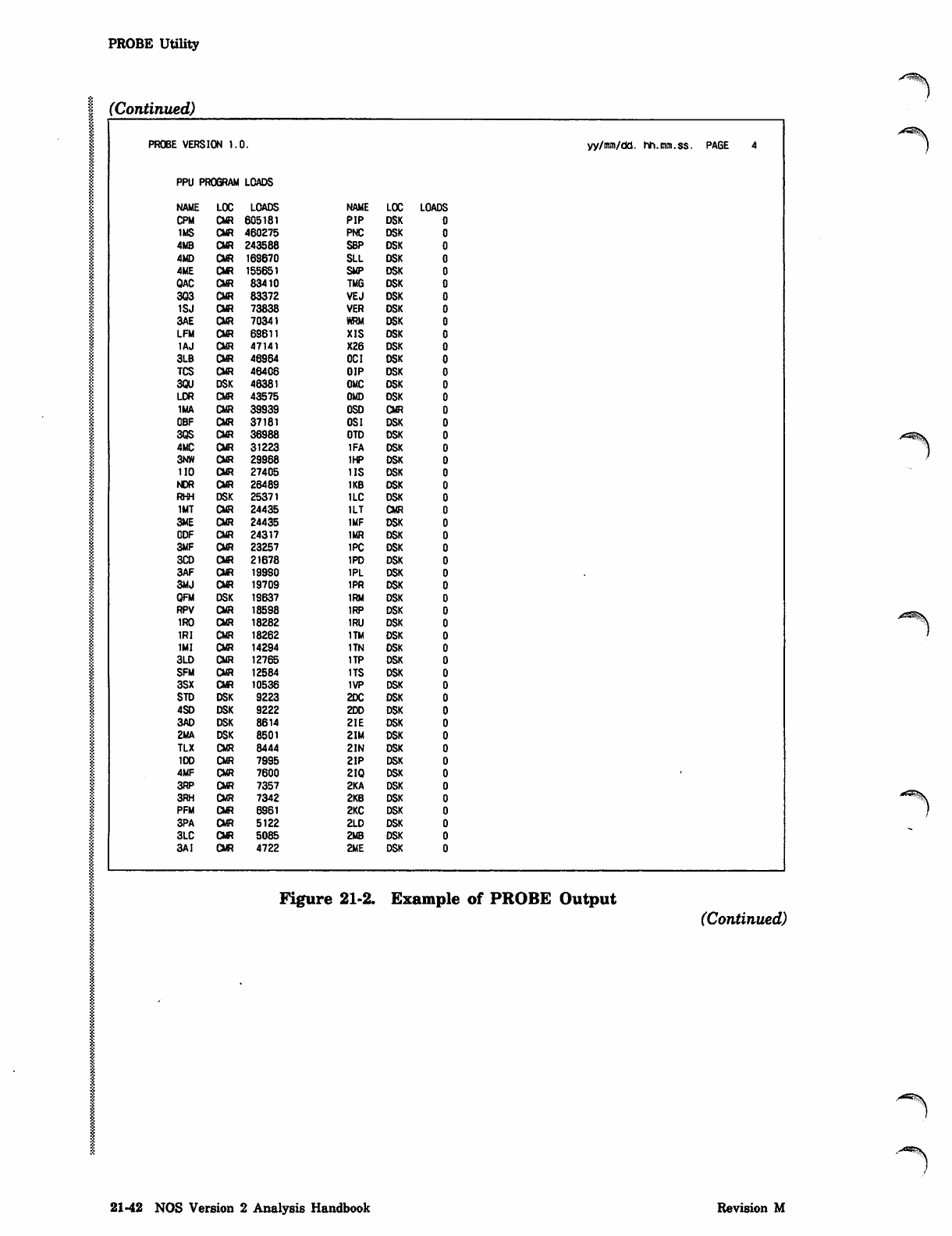
PROBE Utility
(Continued)
.-*m$S
PROBE VERSION 1.0.
PPU PROGRAM LOADS
NAME LOC LOADS NAME LOC LOADS
CPM CMR 605181 PIP DSK
IMS CMR 460275 PNC DSK
4MB CMR 243588 SBP DSK
4MD CMR 169670 SLL DSK
4ME CMR 155651 SMP DSK
QAC CMR 83410 TMG DSK
303 CMR 83372 VEJ DSK
1SJ CMR 73838 VER DSK
3AE CMR 70341 WRM DSK
LFM CMR 69611 XIS DSK
IAJ CMR 47141 X26 DSK
3LB CMR 46964 OCI DSK
TCS CMR 46406 OIP DSK
3QU DSK 46381 OMC DSK
LDR CMR 43575 OMD DSK
1MA CMR 39939 OSD CMR
OBF CMR 37181 OS I DSK
3QS CMR 36988 OTD DSK
4MC CMR 31223 1FA DSK
3NW CMR 29968 1HP DSK
110 CMR 27405 IIS DSK
NDR CMR 26489 1KB DSK
RHH DSK 25371 1LC DSK
IMT CMR 24435 1LT CMR
3ME CMR 24435 IMF DSK
CDF CMR 24317 1MR DSK
3MF CMR 23257 1PC DSK
3CD CMR 21678 IPD DSK
3AF CMR 19990 1PL DSK
3MJ CMR 19709 1PR DSK
QFM DSK 19637 1RM DSK
RPV CMR 18598 1RP DSK
1RO CMR 18282 1RU DSK
1RI CMR 18262 1TM DSK
1MI CMR 14294 1TN DSK
3LD CMR 12765 1TP DSK
SFM CMR 12584 1TS DSK
3SX CMR 10536 1VP DSK
STD DSK 9223 2DC DSK
4SD DSK 9222 2DD DSK
3AD DSK 8614 2IE DSK
2MA DSK 8501 2IM DSK
TLX CMR 8444 2IN DSK
1DD CMR 7995 2IP DSK
4MF CMR 7600 2IQ DSK
3RP CMR 7357 2KA DSK
3RH CMR 7342 2KB DSK
PFM CMR 6861 2KC DSK
3PA CMR 5122 2LD DSK
3LC CMR 5085 2MB DSK
3AI CMR 4722 2ME DSK
yy/mm/dd. hh.mm.ss. PAGE 4
y^^S
Figure 21-2. Example of PROBE Output (Continued)
.•"^**S\
21-42 NOS Version 2 Analysis Handbook Revision M
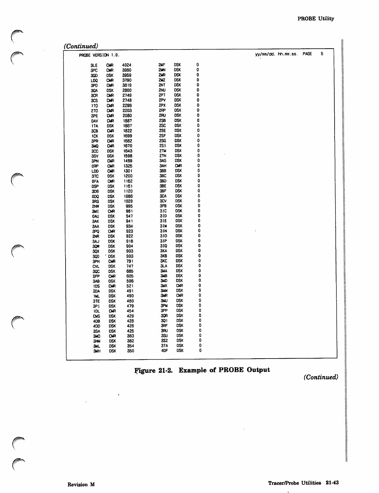
PROBE Utility
(Continued)
jH^OO!?*^
PROBE VERSION 1.0.
3LE CMR 4024 2MF DSK
3PC CMR 3960 2MN DSK
3QD DSK 3959 2MR DSK
LDQ CMR 3790 2MZ DSK
3PD CMR 3619 2NT DSK
3QA DSK 2800 2NU DSK
3CR CMR 2749 2PT DSK
3CS CMR 2748 2PV DSK
1TO CMR 2296 2PX DSK
2T0 CMR 2203 2RP DSK
3PE CMR 2080 2RU DSK
OAV CMR 1887 2SB DSK
1TA DSK 1867 2SC DSK
3CB CMR 1822 2SE DSK
1CK DSK 1699 2SF DSK
3PR CMR 1682 2SG DSK
3MQ CMR 1670 2SI DSK
3CC DSK 1643 2TM DSK
3SV DSK 1598 2TN DSK
3PN CMR 1489 3AG DSK
ORP CMR 1325 3AH CMR
LDD CMR 1301 3BB DSK
3TC DSK 1200 3BC DSK
OFA CMR 1162 3BD DSK
DSP DSK 1161 3BE DSK
3DB DSK 1120 3BF DSK
ODQ DSK 1086 3CA DSK
3RG DSK 1029 3CV DSK
2NW DSK 995 3FB DSK
3MI CMR 981 3IC DSK
OAU DSK 947 3ID DSK
3AK DSK 941 3IE DSK
3AA DSK 934 3IM DSK
3PQ CMR 923 3IN DSK
2NR DSK 922 310 DSK
3AJ DSK 918 3IP DSK
3QW DSK 904 3IQ DSK
3QX DSK 903 3KA DSK
3Q0 ' DSK 903 3KB DSK
3PH CMR 791 3KC DSK
CVL DSK 747 3LA DSK
3QC DSK 685 3MA DSK
SFP CMR 605 3MB DSK
3AB DSK 596 3MD DSK
IDS CMR 521 3MK CMR
3DA DSK 491 3MM DSK
1ML DSK 490 3MR CMR
3TE DSK 480 3MU DSK
3P1 DSK 479 3PM DSK
1DL CMR 454 3PP DSK
CMS DSK 429 3QR DSK
4DB DSK 426 3Q1 DSK
400 DSK 426 3RF DSK
3SA DSK 425 3RU DSK
3M0 CMR 383 3SU DSK
3NM DSK 382 3SZ DSK
3ML DSK 354 3TA DSK
3MH DSK 350 4DF DSK
yy/mm/dd. hh.mm.ss. PAGE
Figure 21-2. Example of PROBE Output (Continued)
/0ms
Revision M Tracer/Probe Utilities 21-43
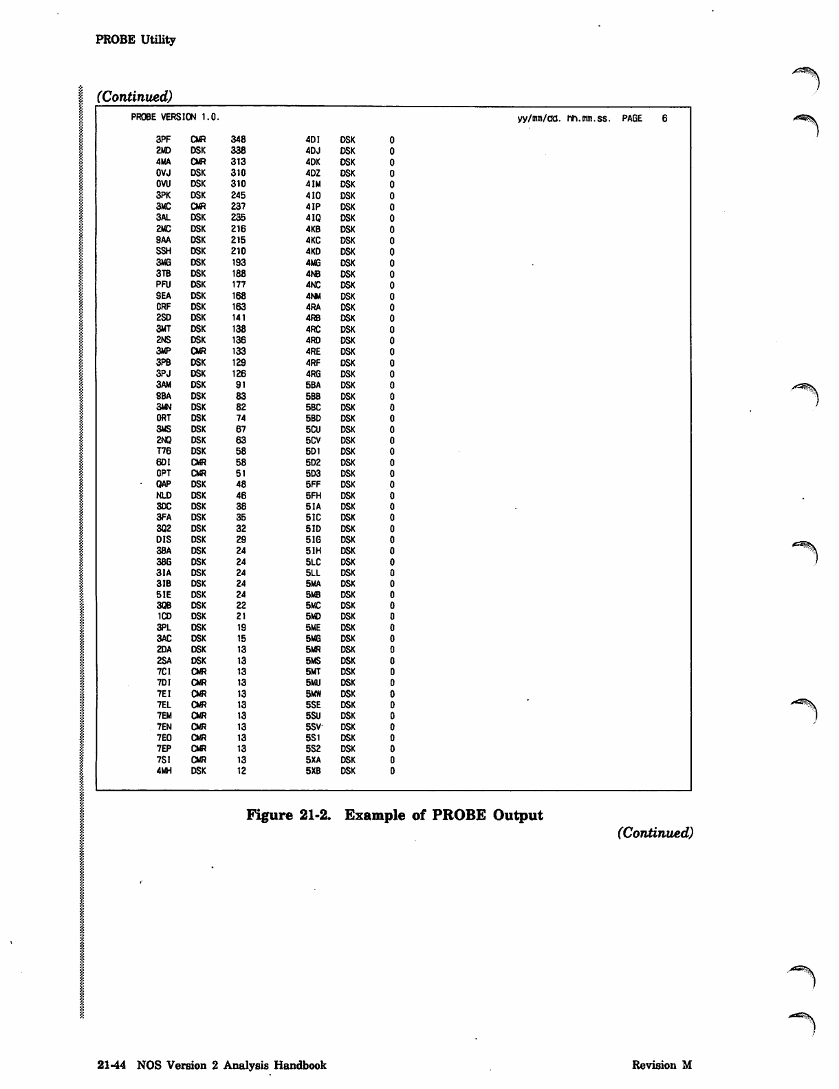
PROBE Utility
I (Continued)
PROBE VERSION 1.0. yy/mm/dd. hh.mm.ss. PAGE 6
3PF CMR 348 4DI DSK
2MD DSK 338 4DJ DSK
4MA CMR 313 4DK DSK
OVJ DSK 310 4DZ DSK
OVU DSK 310 4IM DSK
3PK DSK 245 410 DSK
3MC CMR 237 4 IP DSK
3AL DSK 235 4IQ DSK
2MC DSK 216 4KB DSK
9AA DSK 215 4KC DSK
SSH DSK 210 4KD DSK
3MG DSK 193 4MG DSK
3TB DSK 188 4NB DSK
PFU DSK 177 4NC DSK
SEA DSK 168 4NM DSK
ORF DSK 163 4RA DSK
2SD DSK 141 4RB DSK
3MT DSK 138 4RC DSK
2NS DSK 136 4RD DSK
3MP CMR 133 4RE DSK
3PB DSK 129 4RF DSK
3PJ DSK 126 4RG DSK
3AM DSK 91 5BA DSK
SBA DSK 83 5BB DSK
3MN DSK 82 SBC DSK
ORT DSK 74 5BD DSK
3MS DSK 67 5CU DSK
2NQ DSK 63 5CV DSK
T76 DSK 58 5D1 DSK
6DI CMR 58 5D2 DSK
OPT CMR 51 5D3 DSK
• QAP DSK 48 5FF DSK
NLD DSK 46 5FH DSK
30C DSK 36 5IA DSK
3FA DSK 35 51C DSK
3Q2 DSK 32 5 ID DSK
DIS DSK 29 5IG DSK
3BA DSK 24 5IH DSK
3BG DSK 24 5LC DSK
3IA DSK 24 5LL DSK
3IB DSK 24 5MA DSK
51E DSK 24 5MB DSK
3QB DSK 22 5MC DSK
1CD DSK 21 5MD DSK
3PL DSK 19 5ME DSK
3AC DSK 15 5MG DSK
2DA DSK 13 5MR DSK
2SA DSK 13 5MS DSK
7CI CMR 13 5MT DSK
7DI CMR 13 5MU DSK
7EI CMR 13 5MW DSK
7EL CMR 13 5SE DSK
7EM CMR 13 5SU DSK
7EN CMR 13 5SV DSK
7E0 CMR 13 5S1 DSK
7EP CMR 13 5S2 DSK
7SI CMR 13 5XA DSK
4MH DSK t2 5XB DSK
Figure 21-2. Example of PROBE Output
(Continued)
A^%.
21-44 NOS Version 2 Analysis Handbook Revision M
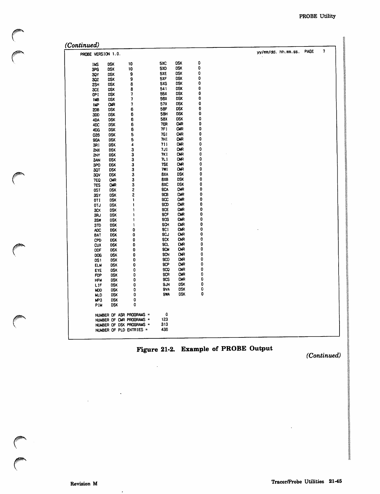
PROBE Utility
(Continued)
PROBE VERSION 1.0. yy/mm/dd. hh.mm.ss. PAGE
r
IMS DSK 10
3PG DSK 10
3QY DSK
3QZ DSK
2SH DSK
3CE DSK
OP I DSK
1MB DSK
IMP CMR
2DB DSK
3DD DSK
4DA DSK
4DC DSK
4DG DSK
026 DSK
SGA DSK
3R1 DSK
2NX DSK
2NY DSK
3AN DSK
3P0 DSK
3QT DSK
3QV DSK
7EQ CMR
7ES CMR
OST DSK
3SY DSK
OTI DSK
OTJ DSK
3CK DSK
3RJ DSK
3SW DSK
3TD DSK
ADC DSK
BAT DSK
CPD DSK
CUX DSK
DDF DSK
DOG DSK
DS1 DSK
ELM DSK
EYE DSK
FDP DSK
HFM DSK
LIF DSK
MDD DSK
MLD DSK
MP3 DSK
PIM DSK
NUMBER OF ASR PROGRAMS
NUMBER OF CMR PROGRAMS
NUMBER OF DSK PROGRAMS
NUMBER OF PLD ENTRIES =
5XC DSK
5XD DSK
5XE DSK
5XF DSK
5XG DSK
541 DSK
55X DSK
56X DSK
57X DSK
58F DSK
58H DSK
58X DSK
7ER CMR
7F1 CMR
7GI CMR
7HI CMR
711 CMR
7JI CMR
7KI CMR
7L1 CMR
7SE CMR
7WI CMR
8XA DSK
8XB DSK
8XC DSK
9CA CMR
9CB OR
9CC CM?
SCO CMR
9CE CMR
9CF CMR
9CG CMR
9CH CMR
9CI CMR
9CJ CMR
9CK CMR
9CL cm
9CM CMR
9CN CMR
9C0 CMR
9CP CMR
9CQ CMR
9CR CMR
9CS CMR
9JN DSK
9VA DSK
9WA DSK
0
123
313
436
Figure 21-2. Example of PROBE Output (Continued)
Revision M Tracer/Probe Utilities 21-45
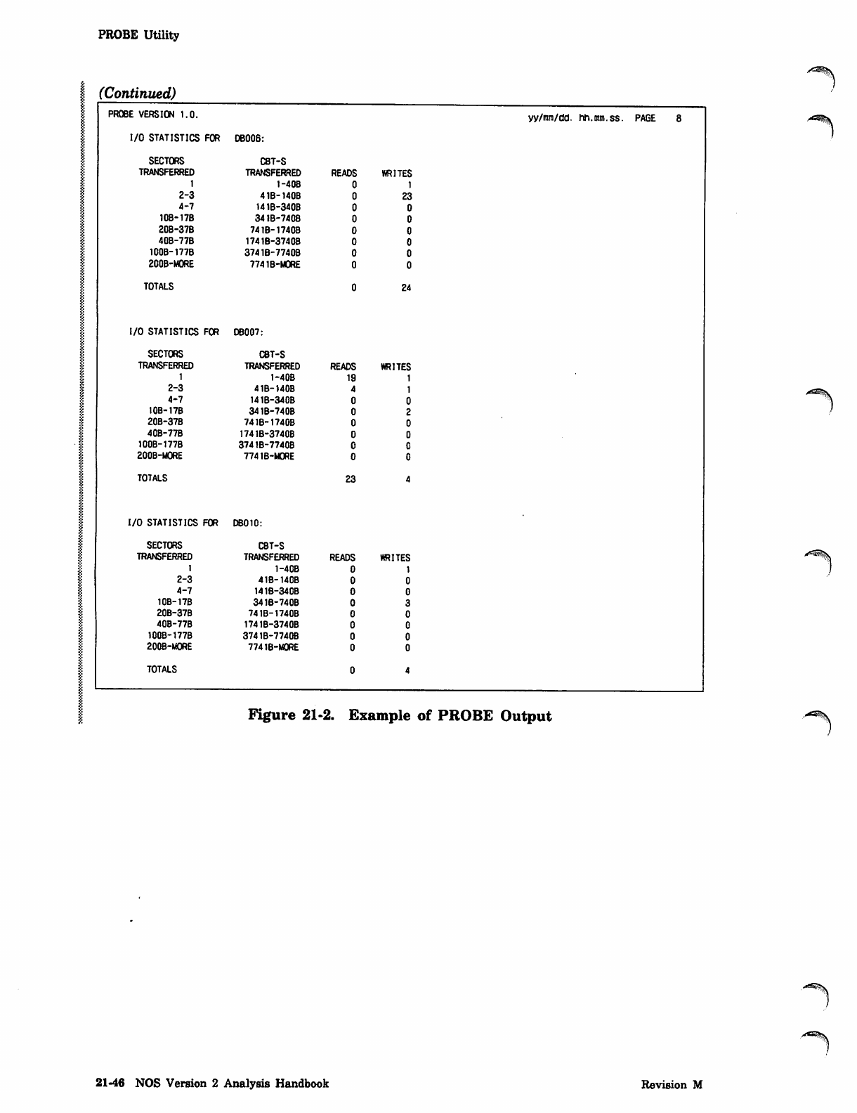
PROBE Utility
(Continued)
PROBE VERSION 1.0.
I/O STATISTICS FOR DB006:
SECTORS CBT-S
TRANSFERRED TRANSFERRED READS WRITES
1I-40B
2-3 41B-140B 23
4-7 141B-340B
10B-17B 341B-740B
20B-37B 741B-1740B
40B-77B 1741B-3740B
100B-177B 3741B-7740B
200B-MORE 7741B-M0RE
TOTALS
I/O STATISTICS FOR DB007:
TOTALS
I/O STATISTICS FOR DB010:
TOTALS
23
24
SECTORS CBT-S
TRANSFERRED TRANSFERRED READS WRITES
11-40B 19
2-3 41B-140B
4-7 141B-340B
10B-17B 341B-740B
20B-37B 741B-1740B
4CB-77B 1741B-3740B
100B-177B 3741B-7740B
200B-MORE 774 IB-MORE
SECTORS CBT-S
TRANSFERRED TRANSFERRED READS WRITES
11-40B
2-3 41B-140B
4-7 141B-340B
10B-17B 341B-740B
20B-37B 741B-1740B
40B-77B 1741B-3740B
100B-177B 3741B-7740B
200B-MORE 774 IB-MORE
yy/i™/dd. hh.mm.ss. PAGE 8
Figure 21-2. Example of PROBE Output
21-46 NOS Version 2 Analysis Handbook Revision M

f*
Appendixes
Character Sets ,t A-l
Glossary , jj.l
Scope 2 Station Facility C-l
Status/Control Register Simulator D-l
680 Programmable Format Control E-l
633/536, 537, and 585 Printer Electronic Vertical Format Unit (EVFU) F-l
881/883 Pack Reformatting Utility .G-l
NOS/VE Address Formats H-l
Management Of Storage Media Defects 1-1
Display Disk File (DDF) Utility J-l
PACKER Utility K-l
J^S

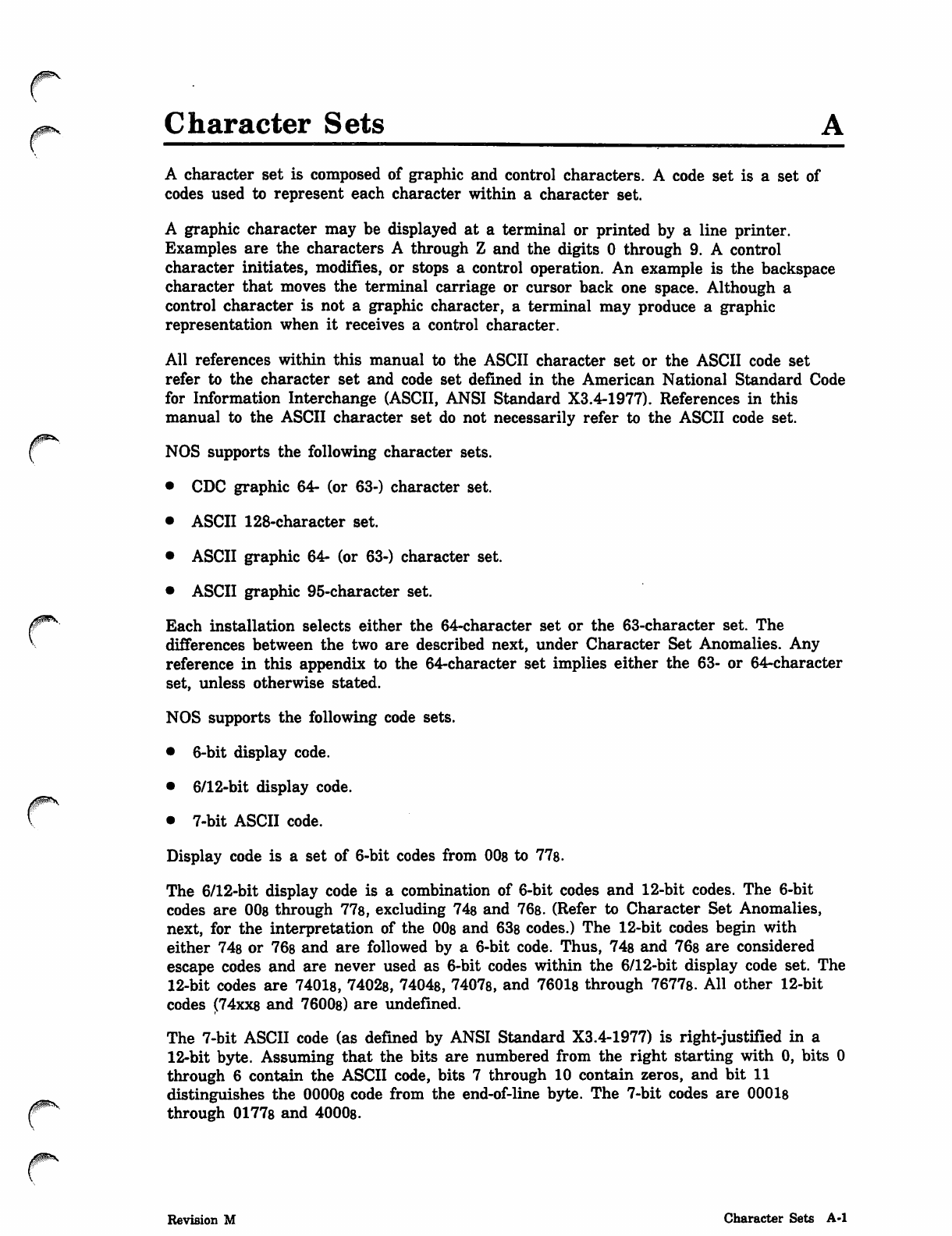
Character Sets
yfHflstfT^Y
r
A character set is composed of graphic and control characters. A code set is a set of
codes used to represent each character within a character set.
A graphic character may be displayed at a terminal or printed by a line printer.
Examples are the characters A through Z and the digits 0 through 9. A control
character initiates, modifies, or stops a control operation. An example is the backspace
character that moves the terminal carriage or cursor back one space. Although a
control character is not a graphic character, a terminal may produce a graphic
representation when it receives a control character.
All references within this manual to the ASCII character set or the ASCII code set
refer to the character set and code set defined in the American National Standard Code
for Information Interchange (ASCII, ANSI Standard X3.4-1977). References in this
manual to the ASCII character set do not necessarily refer to the ASCII code set.
NOS supports the following character sets.
• CDC graphic 64- (or 63-) character set.
• ASCII 128-character set.
• ASCII graphic 64- (or 63-) character set.
• ASCII graphic 95-character set.
Each installation selects either the 64-character set or the 63-character set. The
differences between the two are described next, under Character Set Anomalies. Any
reference in this appendix to the 64-character set implies either the 63- or 64-character
set, unless otherwise stated.
NOS supports the following code sets.
• 6-bit display code.
• 6/12-bit display code.
• 7-bit ASCII code.
Display code is a set of 6-bit codes from 00s to 778.
The 6/12-bit display code is a combination of 6-bit codes and 12-bit codes. The 6-bit
codes are 00s through 77s, excluding 74s and 76s. (Refer to Character Set Anomalies,
next, for the interpretation of the 008 and 63s codes.) The 12-bit codes begin with
either 74s or 76s and are followed by a 6-bit code. Thus, 74s and 76s are considered
escape codes and are never used as 6-bit codes within the 6/12-bit display code set. The
12-bit codes are 74018, 74028, 74048, 74078, and 76018 through 7677s. All other 12-bit
codes (74xx8 and 7600s) are undefined.
The 7-bit ASCII code (as defined by ANSI Standard X3.4-1977) is right-justified in a
12-bit byte. Assuming that the bits are numbered from the right starting with 0, bits 0
through 6 contain the ASCII code, bits 7 through 10 contain zeros, and bit 11
distinguishes the 00008 code from the end-of-line byte. The 7-bit codes are 00018
through 01778 and 4000s.
Revision M Character Sets A-l
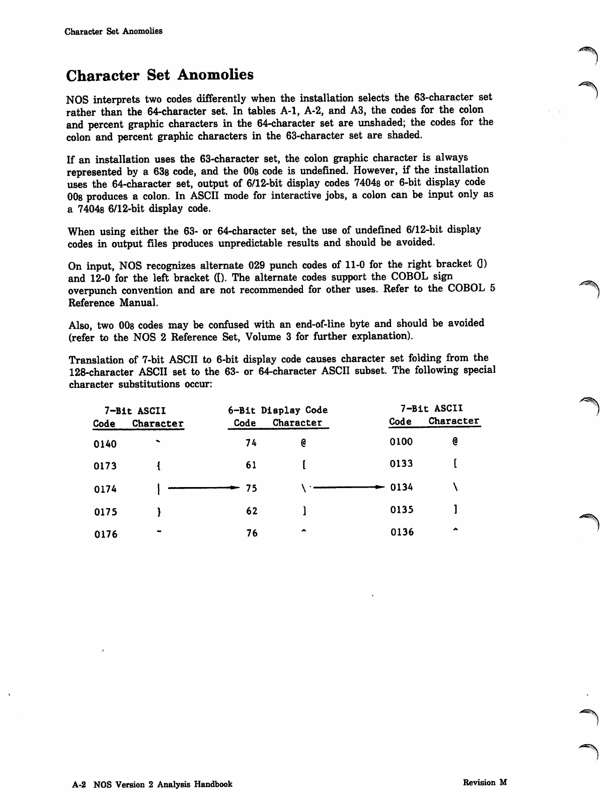
Character Set Anomolies
Character Set Anomolies
NOS interprets two codes differently when the installation selects the 63-character set
rather than the 64-character set. In tables A-l, A-2, and A3, the codes for the colon
and percent graphic characters in the 64-character set are unshaded; the codes for the
colon and percent graphic characters in the 63-character set are shaded.
If an installation uses the 63-character set, the colon graphic character is always
represented by a 63s code, and the 00s code is undefined. However, if the installation
uses the 64-character set, output of 6/12-bit display codes 7404s or 6-bit display code
008 produces a colon. In ASCII mode for interactive jobs, a colon can be input only as
a 74048 6/12-bit display code.
When using either the 63- or 64-character set, the use of undefined 6/12-bit display
codes in output files produces unpredictable results and should be avoided.
On input, NOS recognizes alternate 029 punch codes of 11-0 for the right bracket Q)
and 12-0 for the left bracket ([). The alternate codes support the COBOL sign
overpunch convention and are not recommended for other uses. Refer to the COBOL 5
Reference Manual.
Also, two 008 codes may be confused with an end-of-line byte and should be avoided
(refer to the NOS 2 Reference Set, Volume 3 for further explanation).
Translation of 7-bit ASCII to 6-bit display code causes character set folding from the
128-character ASCII set to the 63- or 64-character ASCII subset. The following special
character substitutions occur:
7-Bit
Code
: ASCII
Character
6-Bit
Code
74
Display Code
Character
@
7-Bit
Code
; ASCII
Character
0140 0100
0173 61 0133
0174 "^ \j l ->**
0175 62 0135
0176 76 0136
A^S
A-2 NOS Version 2 Analysis Handbook Revision M
0ms
Character Set Tables
Character Set Tables
This appendix includes character set tables for interactive jobs, batch jobs, and jobs
involving magnetic tapes. Table A-l is for interactive jobs, and table A-2 is for batch
jobs. Table A-3 is a conversion table used to cross-reference 7-bit ASCII codes and
6/12-bit display codes and to convert ASCII codes from octal to hexadecimal.
Tables A-4, A-5, and A-6 list the magnetic tape codes and their display code
equivalents.
The character set tables are designed so that you can find the character represented by
a code (such as in a dump) or find the code that represents a character. To find the
character represented by a code, look up the code in the column listing the appropriate
code set and then find the character on that line in the column listing the appropriate
character set. To find the code that represents a character, you first look up the
character and then find the code on the same line in the appropriate column.
Interactive Jobs
Table A-l shows the character sets and code sets available to you at an ASCII code
terminal. When in NORMAL mode (specified by the NORMAL command), NOS displays
the ASCII graphic 64-character set and interprets all input and output as display code.
When in ASCII mode (specified by the ASCII command), NOS displays the ASCII
128-character set and interprets all input and output as 6/12-bit display code.
To determine the octal or hexadecimal ASCII code for a character, refer to table A-3.
(Certain terminal definition commands require specification of an ASCII code.)
On output, the US code is reserved for network use and defined as an end-of-line. Use
of this character, except in transparent mode, causes incorrect formatting and possible
loss of output characters.
Batch Jobs
Table A-2 lists the CDC graphic 64-character set, the ASCII graphic 64-character set,
and the ASCII graphic 95-character sets. It also lists the code sets and card punch
codes (026 and 029) that represent the characters.
The 64-character sets use display code as their code set; the 95-character set uses 7-bit
ASCII code. The 95-character set is composed of all the characters in the ASCII
128-character set that can be printed at a line printer (refer to Jobs Using Line
Printers, next). Only 7-bit ASCII code files can be printed using the ASCII graphic
95-character set. To print a 6/12-bit display code file (usually created by an interactive
job in ASCII mode), you must convert the file to 7-bit ASCII code. To do this, you
enter the FCOPY command (refer to the NOS 2 Reference Set, Volume 3). The
95-character set is represented by 7-bit ASCII codes 0040s through 01768.
Revision M Character Sets A-3
Character Set Tables
Jobs Using Line Printers
The batch character set printed depends on the print train used on the line printer to
which the file is sent (refer to the ROUTE command in the NOS 2 Reference Set,
Volume 3). The following are the print trains corresponding to each of the batch
character sets.
Character Set
CDC graphic 64-character set
ASCII graphic 64-character set
ASCII graphic 95-character set
Print Train
PSU Printer
Print Band
596-1
596-5 530-1
596-6 530-2
The characters of the default 596-1 print train are listed in the table A-2 column
labeled CDC Graphic (64 Character); the 596-5 print train characters are listed in the
table A-2 column labeled ASCII Graphic (64 Character); and the 596-6 print train
characters are listed in the table A-2 column labeled ASCII Graphic (95 Character).
If a transmission error occurs when printing a line, the system prints the line again.
The CDC graphic print train prints a concatenation symbol ( r* ) in the first printable
column of the repeated listing of the line. The ASCII print trains print an underline
(_) instead of the concatenation symbol.
If an unprintable character exists in a line (that is, a 7-bit ASCII code outside the
range 0040s through 0176s), the number sign (#) appears in the first printable column
of a print line, and a space replaces the unprintable character.
To route and correctly print a 6/12-bit display code file on a line printer with the
ASCII graphic 95-character set, you must convert the 6/12-bit display code file to a
7-bit ASCII code file with the FCOPY command (refer to the NOS 2 Reference Set,
Volume 3). The resulting 7-bit ASCII file can be routed to a line printer (refer to the
ROUTE command in the NOS 2 Reference Set, Volume 3) but cannot be output at an
interactive terminal.
A-4 NOS Version 2 Analysis Handbook Revision M
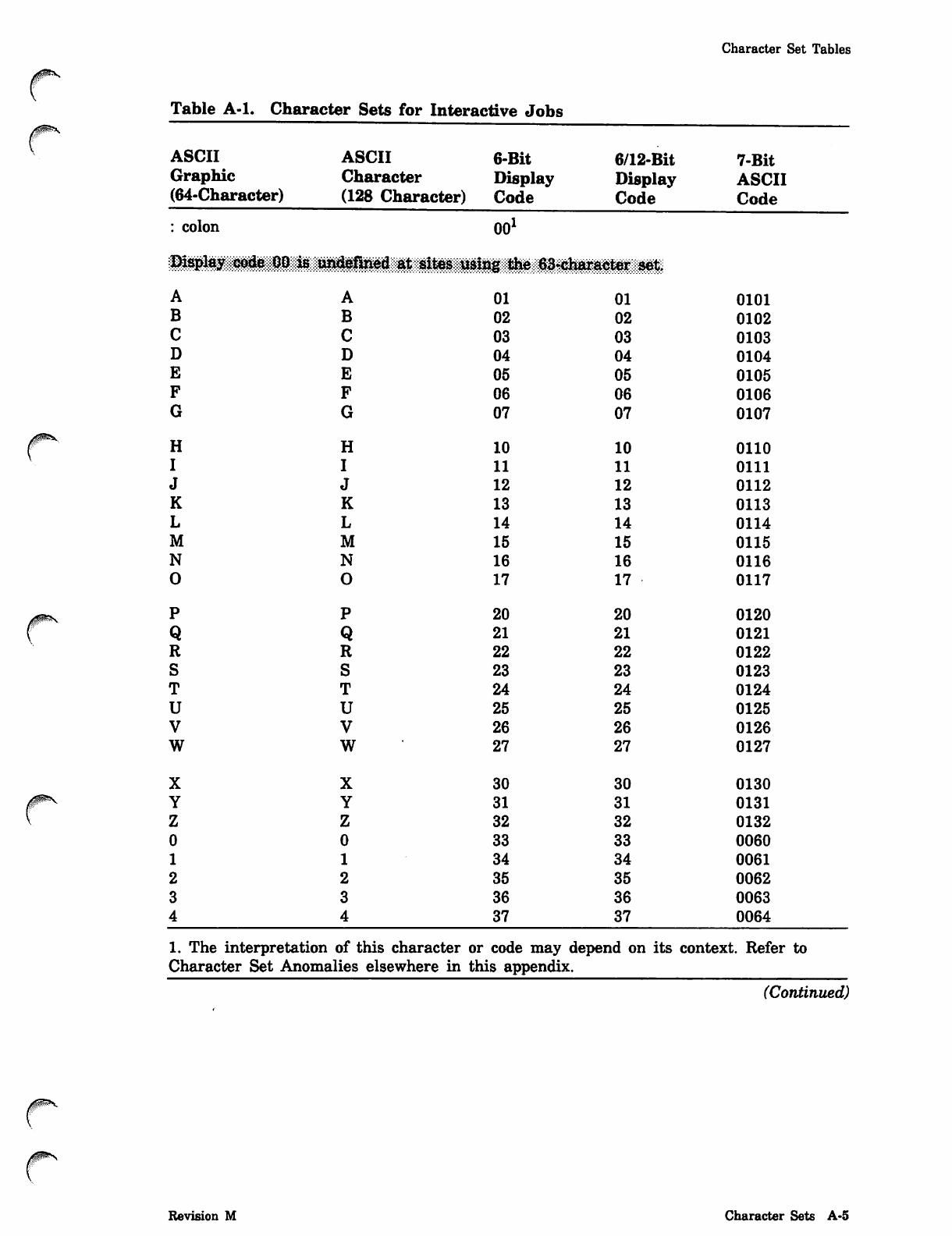
Character Set Tables
Table A-l. Character Sets for Interactive Jobs
yams
ASCII
Graphic
(64-Character)
ASCII
Character
(128 Character)
6-Bit
Display
Code
6/12-Bit
Display
Code
7-Bit
ASCII
Code
colon 00
Display code 80 is undefined at sites using the 63*charaoter set.
A
B
C
D
E
F
G
H
I
J
K
L
M
N
0
P
Q
R
S
T
U
V
W
A
B
C
D
E
F
G
H
I
J
K
L
M
N
O
P
Q
R
S
T
U
V
w
01
02
03
04
05
06
07
10
11
12
13
14
15
16
17
20
21
22
23
24
25
26
27
01
02
03
04
05
06
07
10
11
12
13
14
15
16
17
20
21
22
23
24
25
26
27
0101
0102
0103
0104
0105
0106
0107
0110
0111
0112
0113
0114
0115
0116
0117
0120
0121
0122
0123
0124
0125
0126
0127
0ms
30
31
32
33
34
35
36
37
30
31
32
33
34
35
36
37
0130
0131
0132
0060
0061
0062
0063
0064
1. The interpretation of this character or code may depend on its context. Refer to
Character Set Anomalies elsewhere in this appendix.
(Continued)
Revision M Character Sets A-5
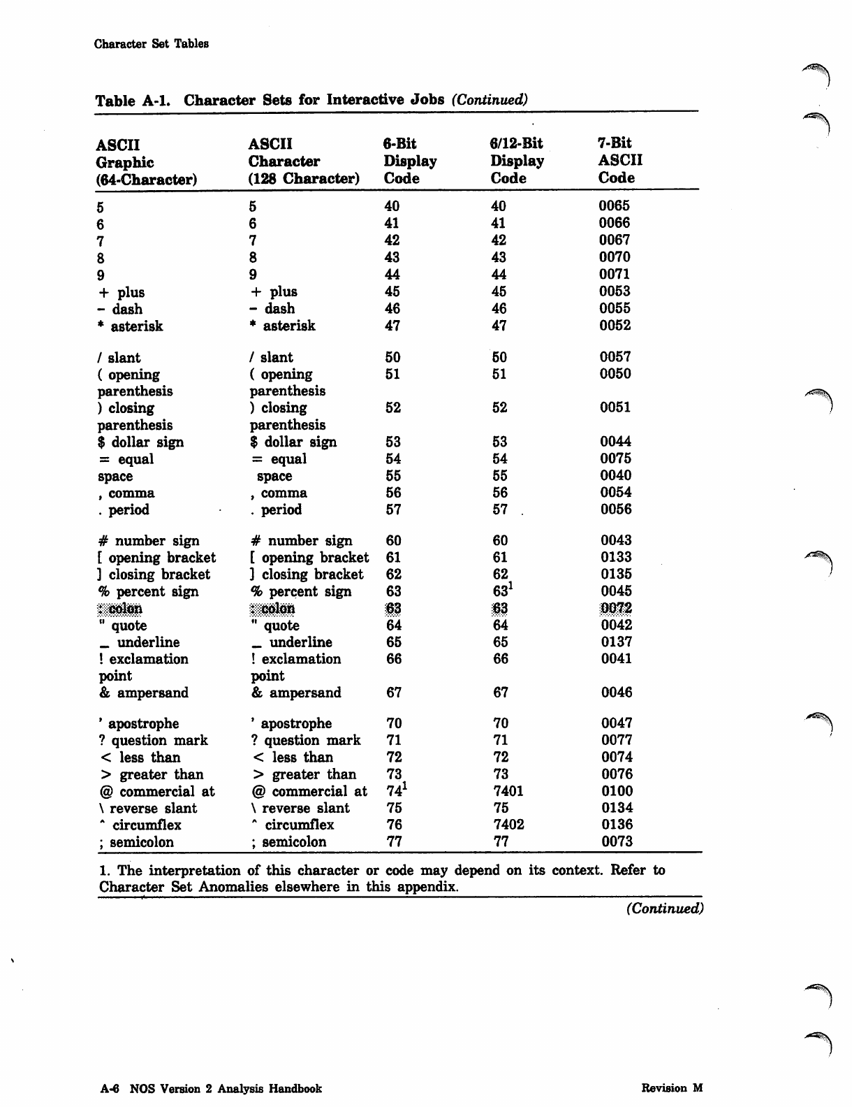
Character Set Tables
Table A-l. Character Sets for Interactive Jobs (Continued)
ASCII ASCII 6-Bit 6/12-Bit 7-Bit
Graphic Character Display Display ASCII
(64-Character) (128 Character) Code Code Code
5540 40 0065
6641 41 0066
7742 42 0067
8843 43 0070
9944 44 0071
+ plus + plus 45 45 0053
- dash - dash 46 46 0055
* asterisk * asterisk 47 47 0052
/ slant / slant 50 50 0057
( opening ( opening 51 51 0050
parenthesis parenthesis
) closing ) closing 52 52 0051
parenthesis parenthesis
$ dollar sign $ dollar sign 53 53 0044
= equal = equal 54 54 0075
space space 55 55 0040
, comma , comma 56 56 0054
. period . period 57 57 . 0056
# number sign # number sign 60 60 0043
[ opening bracket [ opening bracket 61 61 0133
] closing bracket ] closing bracket 62 62 0135
% percent sign % percent sign 63 631 0045
iiiiii iiiiii 63 63 mm
" quote " quote 64 64 0042
_ underline _ underline 65 65 0137
! exclamation ! exclamation 66 66 0041
point point
& ampersand & ampersand 67 67 0046
' apostrophe ' apostrophe 70 70 0047
? question mark ? question mark 71 71 0077
< less than < less than 72 72 0074
> greater than > greater than 73 73 0076
@ commercial at @ commercial at 741 7401 0100
\ reverse slant \ reverse slant 75 75 0134
A circumflex A circumflex 76 7402 0136
; semicolon ; semicolon 77 77 0073
1. The interpretation of this character or code may depend on its context. Refer to
Character Set Anomalies elsewhere in this appendix.
(Continued)
■^^fev
A-6 NOS Version 2 Analysis Handbook Revision M
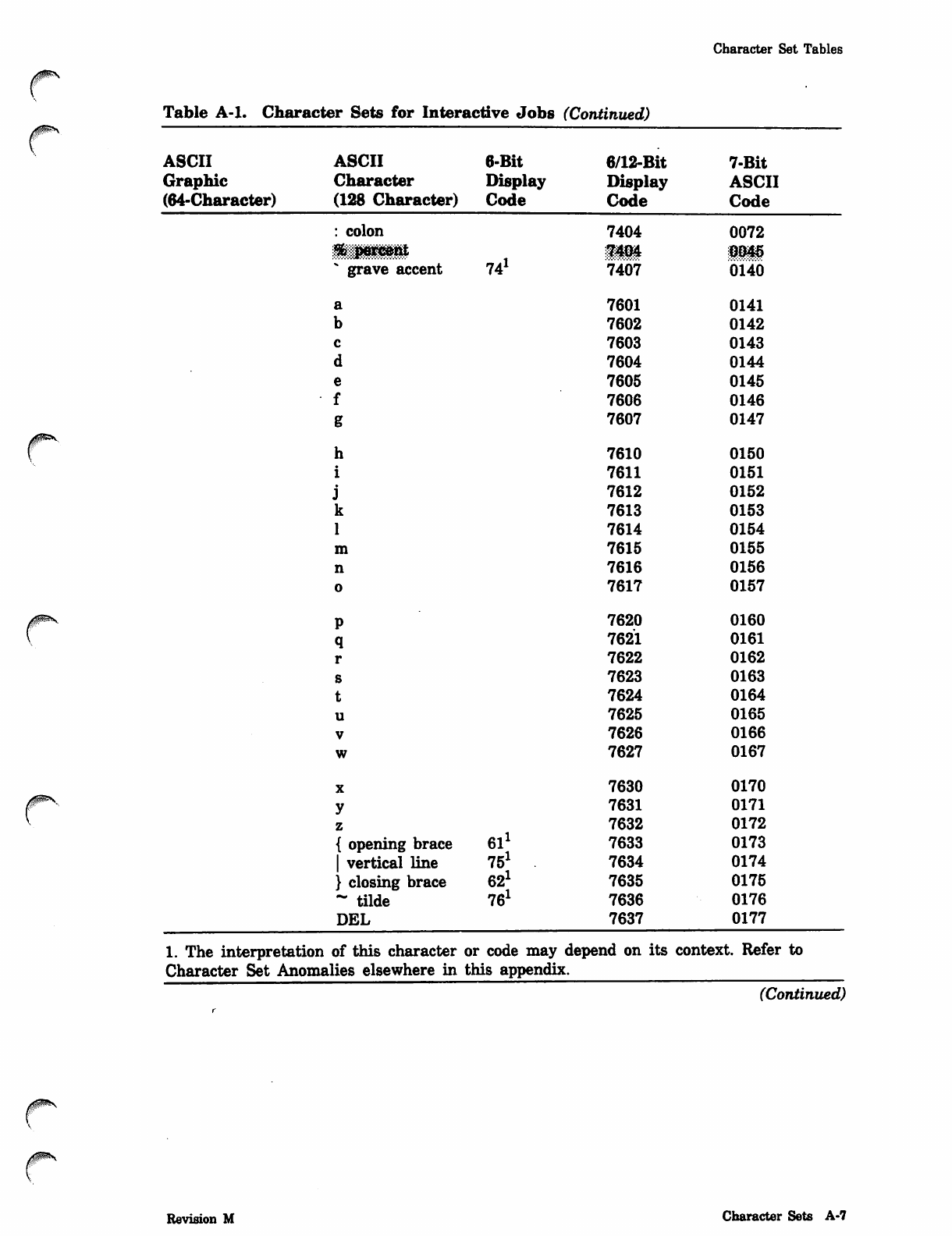
Character Set Tables
0nm*\
Table A-l. Character Sets for Interactive Jobs (Continued)
ASCII
Graphic
(64-Character)
ASCII 6-Bit 6/12-Bit 7-Bit
Character Display Display ASCII
(128 Character) Code Code Code
: colon
* grave accent 741
h
i
jk
1
m
n
o
P
q
r
s
t
u
V
w
X
y
z
{ opening brace 61
| vertical line 75
} closing brace 62
~ tilde 761
DEL
7404
7404
7407
7601
7602
7603
7604
7605
7606
7607
7610
7611
7612
7613
7614
7615
7616
7617
7620
7621
7622
7623
7624
7625
7626
7627
7630
7631
7632
7633
7634
7635
7636
7637
0072
0045
0140
0141
0142
0143
0144
0145
0146
0147
0150
0151
0152
0153
0154
0155
0156
0157
0160
0161
0162
0163
0164
0165
0166
0167
0170
0171
0172
0173
0174
0175
0176
0177
1. The interpretation of this character or code may depend on its context. Refer to
Character Set Anomalies elsewhere in this appendix.
(Continued)
Revision M Character Sets A-7
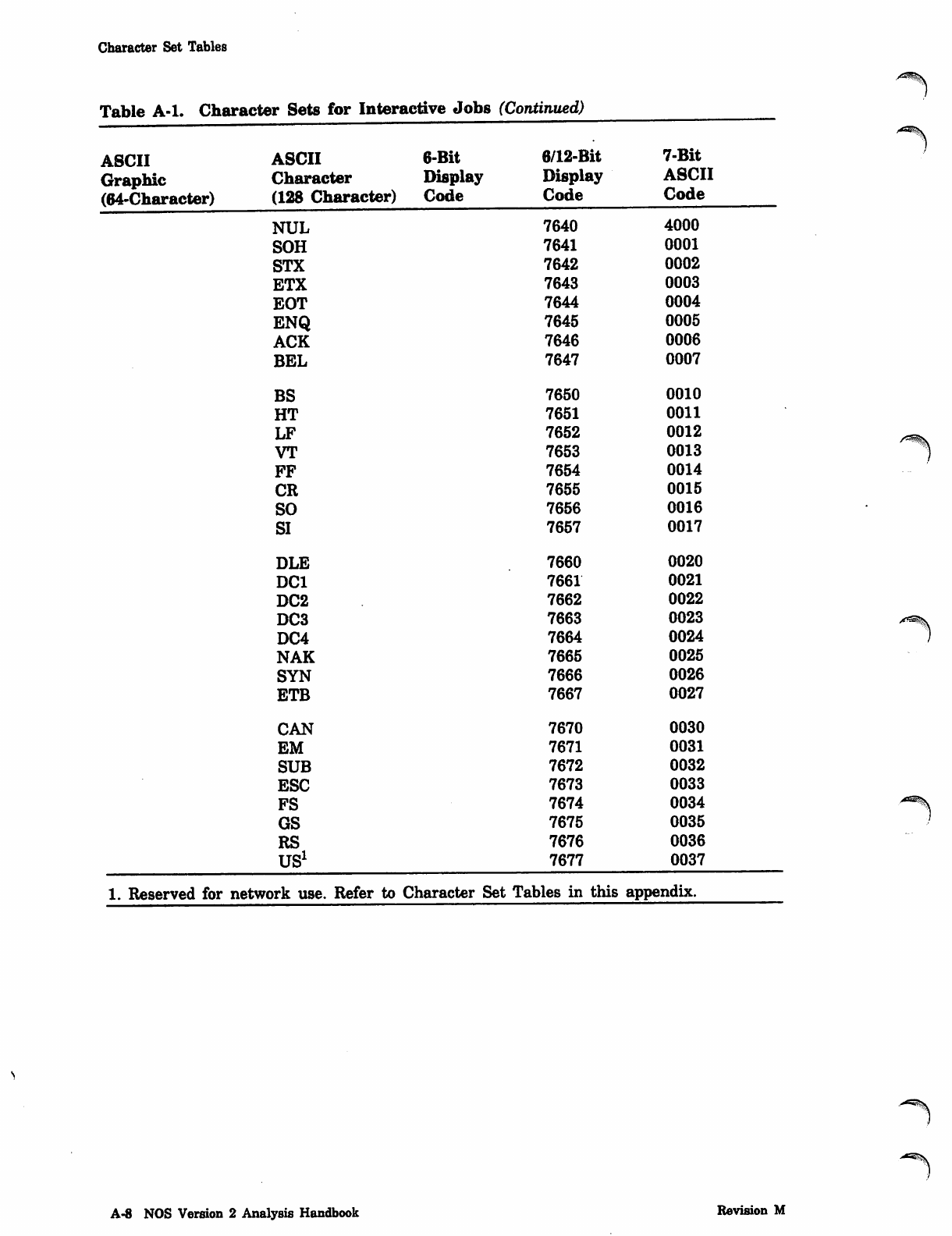
Character Set Tables
Table A-l. Character Sets for Interactive Jobs (Continued)
ASCII ASCII 6-Bit 6/12-Bit 7-Bit
Graphic Character Display Display ASCII
(64-Character) (128 Character) Code Code Code
NUL 7640 4000
SOH 7641 0001
STX 7642 0002
ETX 7643 0003
EOT 7644 0004
ENQ 7645 0005
ACK 7646 0006
BEL 7647 0007
BS 7650 0010
HT 7651 0011
LF 7652 0012
VT 7653 0013
FF 7654 0014
CR 7655 0015
SO 7656 0016
SI 7657 0017
DLE 7660 0020
DC1 7661 0021
DC2 7662 0022
DC3 7663 0023
DC4 7664 0024
NAK 7665 0025
SYN 7666 0026
ETB 7667 0027
CAN 7670 0030
EM 7671 0031
SUB 7672 0032
ESC 7673 0033
FS 7674 0034
GS 7675 0035
RS 7676 0036
US1 7677 0037
1. Reserved for network use. Refer to Character Set Tables in this appendix.
A-8 NOS Version 2 Analysis Handbook Revision M
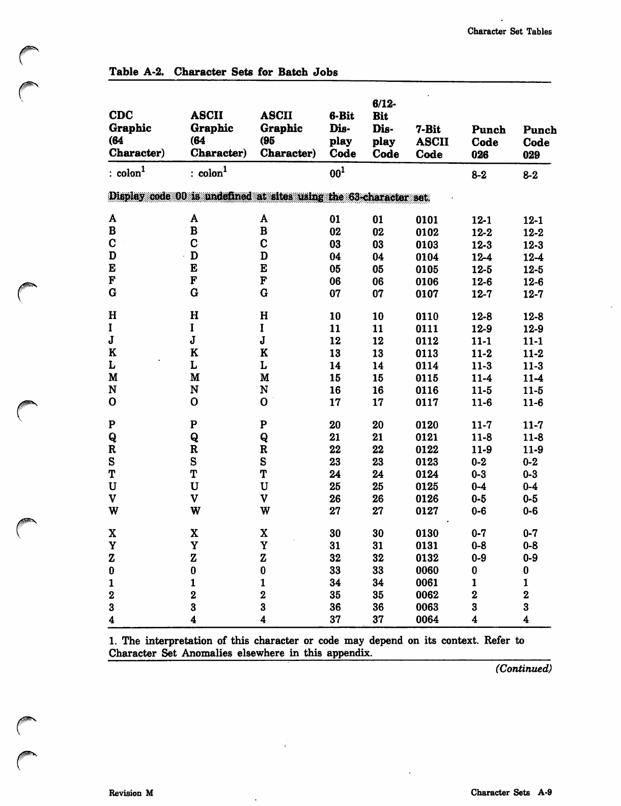
Character Set Tables
y ^ s
Table A-2. Character Sets for Batch Jobs
6/12-
CDC ASCII ASCII 6-Bit Bit
Graphic Graphic Graphic Dis Dis 7-Bit Punch Punch
(64 (64 (95 play play ASCII Code Code
Character) Character) Character) Code Code Code 026 029
: colon1 : colon1 OO1 8-2 8-2
Display c^ at sites using the 63«character set
AAA01 01 0101 12-1 12-1
B B B 02 02 0102 12-2 12-2
C C C 03 03 0103 12-3 12-3
D D D04 04 0104 12-4 12-4
E E E05 05 0105 12-5 12-5
F F F06 06 0106 12-6 12-6
G GG07 07 0107 12-7 12-7
H H H 10 10 0110 12-8 12-8
I I I 11 11 0111 12-9 12-9
J J J12 12 0112 11-1 11-1
K K K13 13 0113 11-2 11-2
L L L 14 14 0114 11-3 11-3
M MM15 15 0115 11-4 11-4
N N N 16 16 0116 11-5 11-5
0 0 0 17 17 0117 11-6 11-6
P PP20 20 0120 11-7 11-7
Q QQ21 21 0121 11-8 11-8
R RR22 22 0122 11-9 11-9
S SS23 23 0123 0-2 0-2
T T T 24 24 0124 0-3 0-3
U UU25 25 0125 0-4 0-4
V VV26 26 0126 0-5 0-5
W W w27 27 0127 0-6 0-6
X X X 30 30 0130 0-7 0-7
Y Y Y 31 31 0131 0-8 0-8
Z Z z32 32 0132 0-9 0-9
00 0 33 33 0060
1 1 1 34 34 0061
2 2 2 35 35 0062
3 3 336 36 0063
4 4 4 37 37 0064
1. The interpretation of this character or code may depend on its context. Refer to
Character Set Anomalies elsewhere in this appendix.
(Continued)
yim-s
Revision M Character Sets A-9
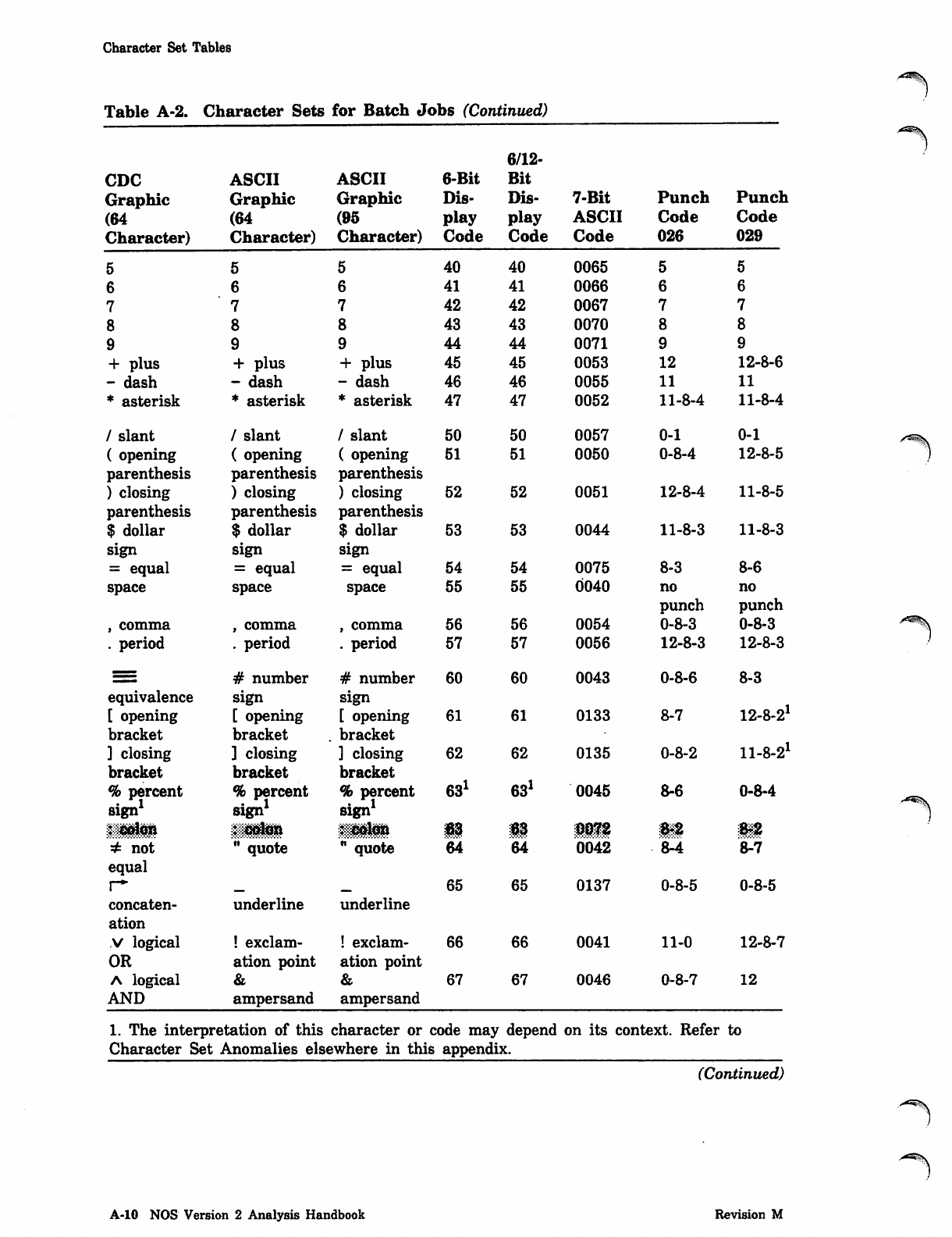
Character Set Tables
Table A-2. Character Sets for Batch Jobs (Continued)
6/12-
CDC ASCII ASCII 6-Bit Bit
Graphic Graphic Graphic Dis Dis 7-Bit Punch Punch
(64 (64 (95 play play ASCII Code Code
Character) Character) Character) Code Code Code 026 029
5 5 540 40 0065
6 6 641 41 0066
7 7 7 42 42 0067
88843 43 0070
9 9944 44 0071
+ plus + plus + plus 45 45 0053 12 12-8-6
- dash - dash - dash 46 46 0055 11 11
* asterisk * asterisk * asterisk 47 47 0052 11-8-4 11-8-4
/ slant / slant / slant 50 50 0057 0-1 0-1
( opening ( opening ( opening 51 51 0050 0-8-4 12-8-5
parenthesis parenthesis parenthesis
) closing ) closing ) closing 52 52 0051 12-8-4 11-8-5
parenthesis parenthesis parenthesis
$ dollar $ dollar $ dollar 53 53 0044 11-8-3 11-8-3
sign sign sign
= equal = equal = equal 54 54 0075 8-3 8-6
space space space 55 55 0040 no
punch
no
punch
, comma , comma , comma 56 56 0054 0-8-3 0-8-3
. period . period . period 57 57 0056 12-8-3 12-8-3
=# number # number 60 60 0043 0-8-6 8-3
equivalence sign sign
[ opening [ opening [ opening 61 61 0133 8-7 12-8-21
bracket bracket . bracket
] closing ] closing ] closing 62 62 0135 0-8-2 11-8-21
bracket bracket bracket
% percent % percent
sign1
% percent 631 631 0045 8-6 0-8-4
sign1 sign1
§§$$§!$& iUHl ^muf 63 63 0072 ms. 8-2
^ n ot " quote " quote 64 64 0042 . £4 fcV7
equal
r* mtam 65 65 0137 0-8-5 0-8-5
concaten underline underline
ation
v logical ! exclam ! exclam 66 66 0041 11-0 12-8-7
OR ation point ation point
a logical 67 67 0046 0-8-7 12
AND ampersand ampersand
1. The interpretation of this character or code may depend on its context. Refer to
Character Set Anomalies elsewhere in this appendix.
(Continued)
A^-^S.
•/^^\
A-10 NOS Version 2 Analysis Handbook Revision M
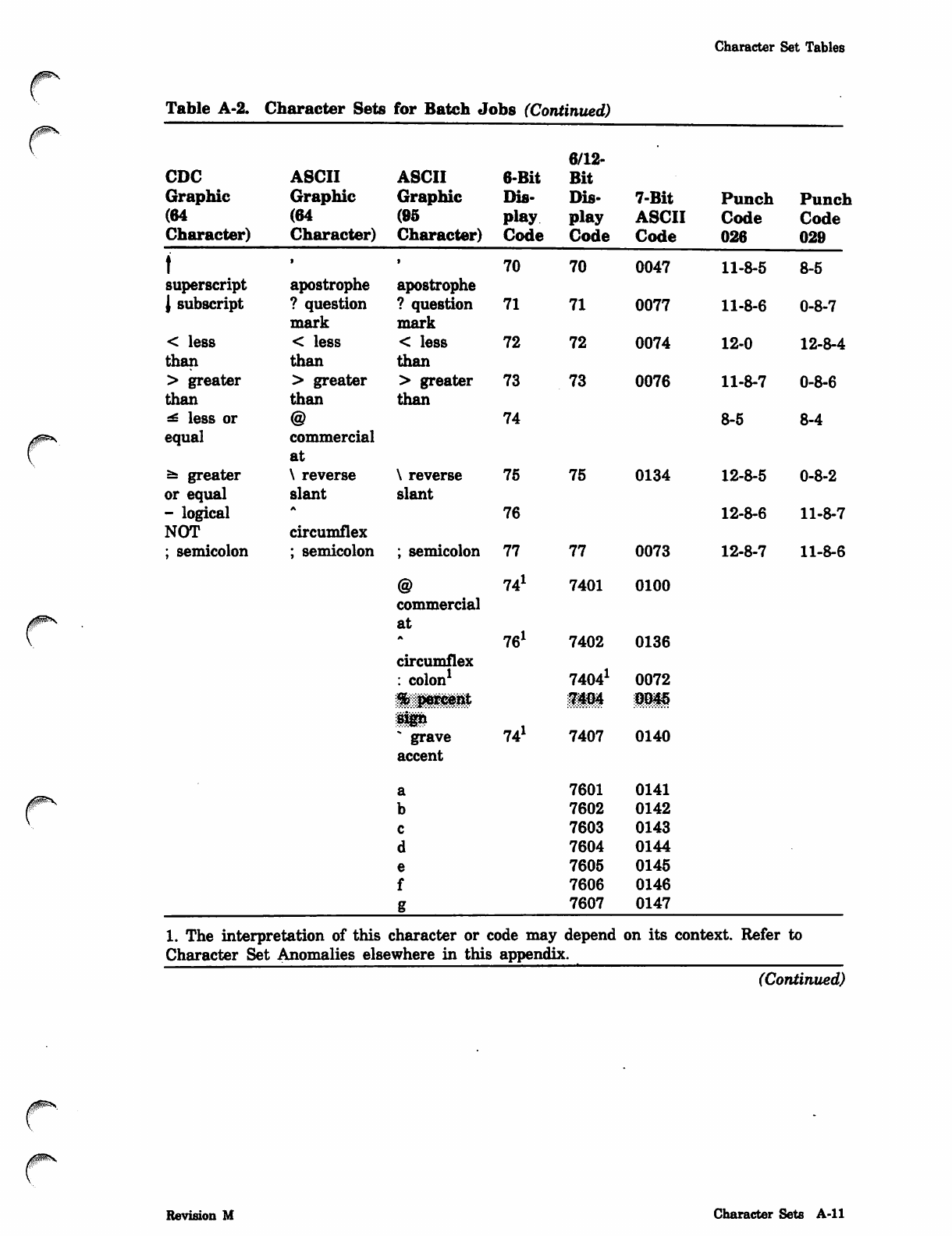
Character Set Tables
Table A-2. Character Sets for Batch Jobs (Continued)
CDC ASCII ASCII 6-Bit
Graphic Graphic Graphic Dis-
(64 (64 (95 play
Character) Character) Character) Code
t
superscript
J subscript
< less
than
> greater
than
^ less or
equal
Ss greater
or equal
- logical
NOT
; semicolon
6/12-
Bit
Dis- 7-Bit
play ASCII
Code Code
apostrophe
? question
mark
< less
than
> greater
than
@
commercial
at
\ reverse
slant
A
circumflex
; semicolon
apostrophe
? question
mark
< less
than
> greater
than
\ reverse
slant
; semicolon
@
commercial
at
A
circumflex
: colon1
70
71
72
73
74
75
76
77
741
761
70 0047
71 0077
72 0074
73 0076
75 0134
77 0073
7401 0100
7402 0136
74041 0072
grave
accent
a
b
c
d
e
f
74J
iHi iii
7407 0140
7601 0141
7602 0142
7603 0143
7604 0144
7605 0145
7606 0146
7607 0147
Punch Punch
Code Code
026 029
11-8-5
11-8-6
12-0
11-8-7
8-5
8-5
0-8-7
12-8-4
0-8-6
8-4
12-8-5 0-8-2
12-8-6 11-8-7
12-8-7 11-8-6
1. The interpretation of this character or code may depend on its context. Refer to
Character Set Anomalies elsewhere in this appendix.
(Continued)
Revision M Character Sets A-ll
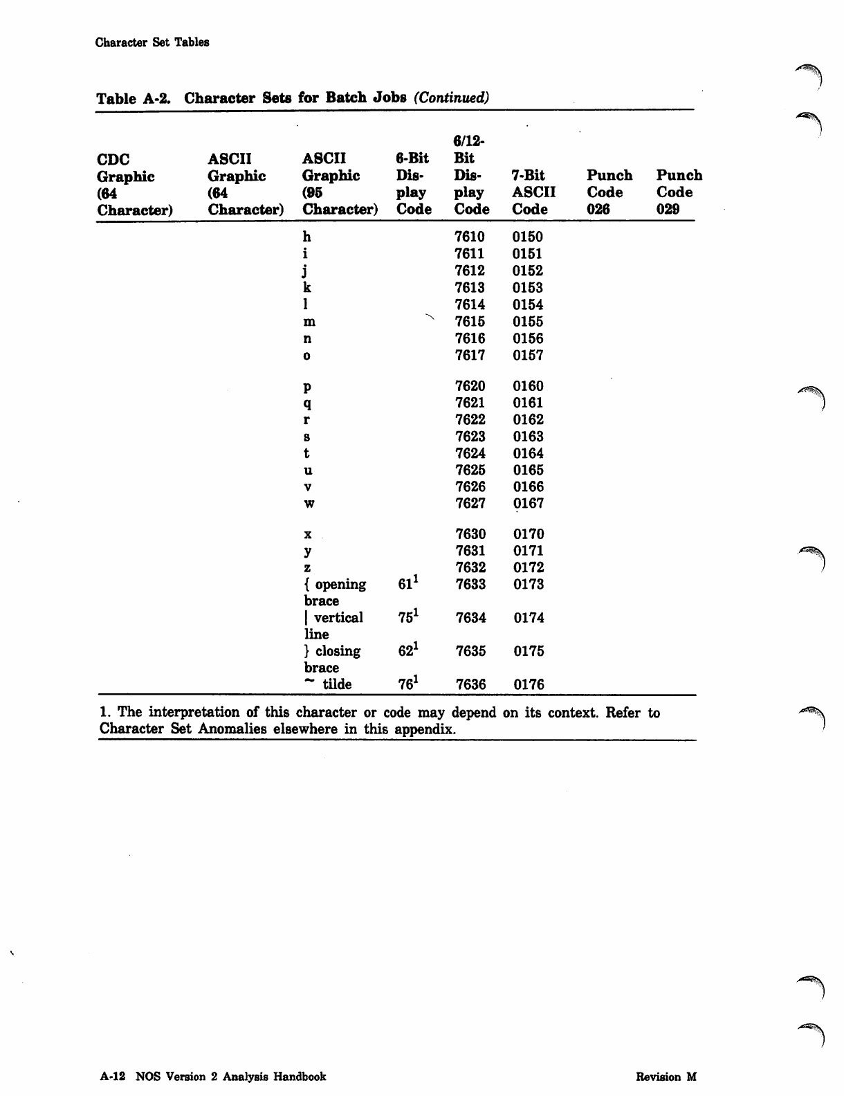
Character Set Tables
Table A-2. Character Sets for Batch Jobs (Continued)
6/12-
CDC ASCII ASCII 6-Bit Bit
Graphic Graphic Graphic Dis- Dis- 7-Bit Punch Punch
(64 (64 (95 play play ASCII Code Code
Character) Character) Character) Code Code Code 026 029
h
i
j
k
1
m
n
o
7610
7611
7612
7613
7614
7615
7616
7617
0150
0151
0152
0153
0154
0155
0156
0157
P
q
r
s
t
u
V
w
7620
7621
7622
7623
7624
7625
7626
7627
0160
0161
0162
0163
0164
0165
0166
0167
y
z
{ opening
brace
| vertical
line
} closing
brace
- tilde
61J
75J
62J
76J
7630
7631
7632
7633
7634
7635
7636
0170
0171
0172
0173
0174
0175
0176
1. The interpretation of this character or code may depend on its context. Refer to
Character Set Anomalies elsewhere in this appendix.
y^^^V
A-12 NOS Version 2 Analysis Handbook Revision M
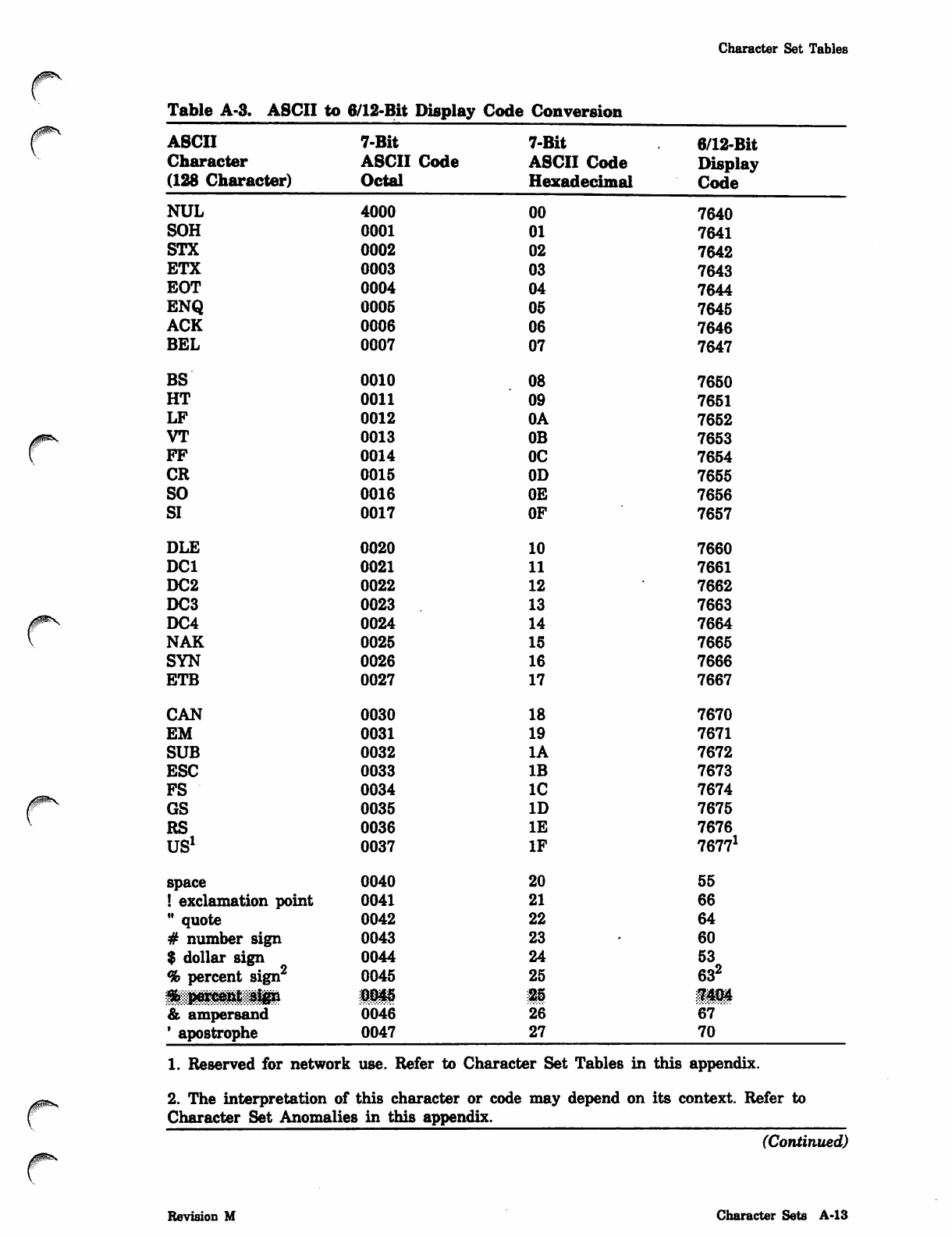
Character Set Tables
Table A-3. ASCII to 6/12-Bit Display Code Conversion
ASCII 7-Bit 7-Bit 6/12-Bit
Character ASCII Code ASCII Code Display
(128 Character) Octal Hexadecimal Code
NUL 4000 00 7640
SOH 0001 01 7641
STX 0002 02 7642
ETX 0003 03 7643
EOT 0004 04 7644
ENQ 0005 05 7645
ACK 0006 06 7646
BEL 0007 07 7647
BS 0010 08 7650
HT 0011 09 7651
LF 0012 0A 7652
VT 0013 0B 7653
FF 0014 OC 7654
CR 0015 0D 7655
SO 0016 0E 7656
SI 0017 OF 7657
DLE 0020 10 7660
DC1 0021 11 7661
DC2 0022 12 7662
DC3 0023 13 7663
DC4 0024 14 7664
NAK 0025 15 7665
SYN 0026 16 7666
ETB 0027 17 7667
CAN 0030 18 7670
EM 0031 19 7671
SUB 0032 IA 7672
ESC 0033 IB 7673
FS 0034 IC 7674
GS 0035 ID 7675
RS 0036 IE 7676
US1 0037 IF 76771
space 0040 20 55
! exclamation point 0041 21 66
" quote 0042 22 64
# number sign 0043 23 60
$ dollar sign 0044 24 53
% percent sign2 0045 25 632
^;:;::pedW^tl||gn 0045 25 7404
& ampersand 0046 26 67
' apostrophe 0047 27 70
1. Reserved for network use. Refer to Character Set Tables in this appendix.
/~^ 2. The interpretation of this character or code may depend on its context. Refer to
f Character Set Anomalies in this appendix.
(Continued)
Revision M Character Sets A-13
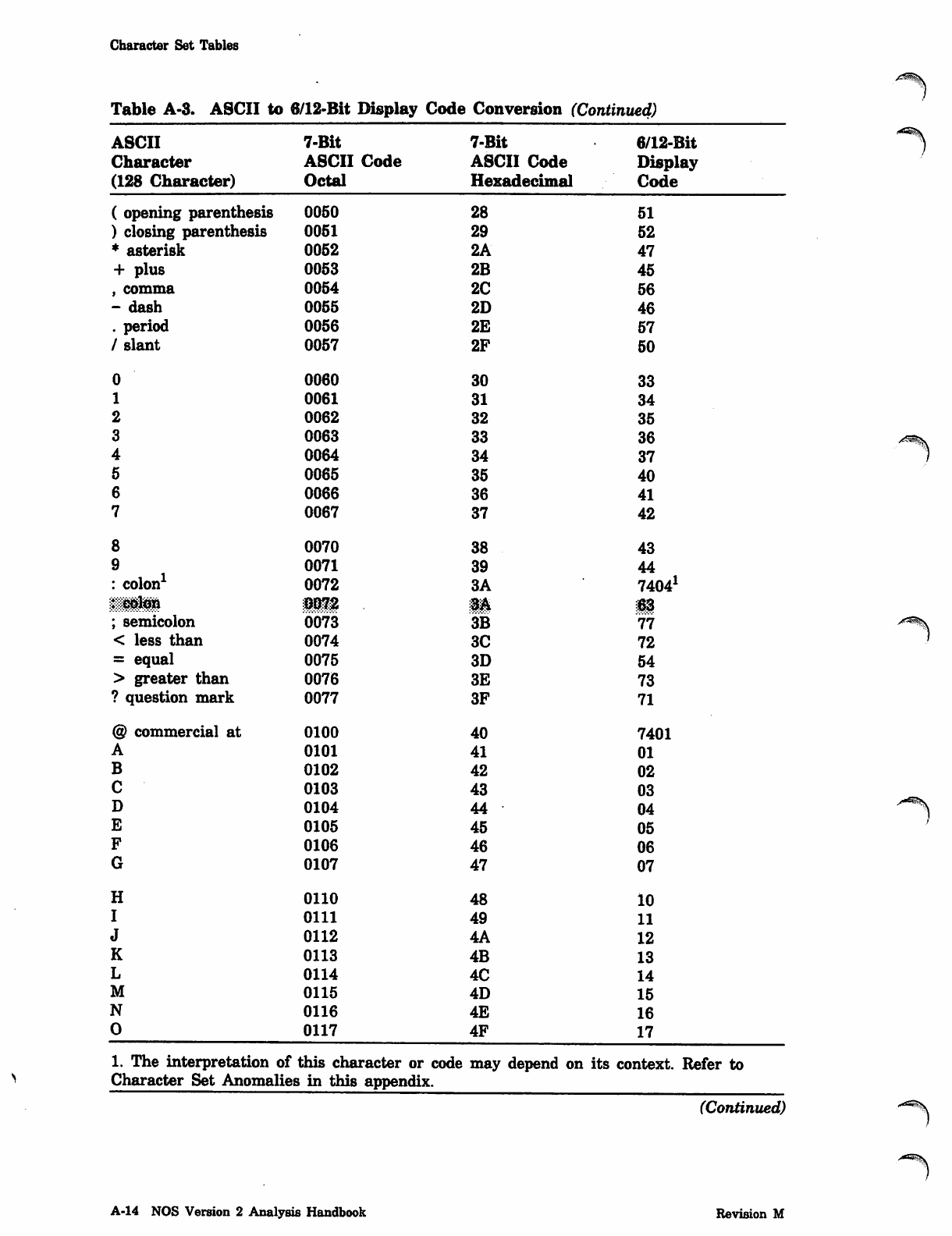
Character Set Tables
Table A-3. ASCII to 6/12-Bit Display Code Conversion (Continued)
ASCII 7-Bit 7-Bit 6/12-Bit
Character ASCII Code ASCII Code Display
(128 Character) Octal Hexadecimal Code
( opening parenthesis 0050 28 51
) closing parenthesis 0051 29 52
* asterisk 0052 2A 47
+ plus 0053 2B 45
, comma 0054 2C 56
- dash 0055 2D 46
. period 0056 2E 57
/ slant 0057 2F 50
00060 30 33
10061 31 34
20062 32 35
30063 33 36
40064 34 37
50065 35 40
60066 36 41
70067 37 42
80070 38 43
90071 39 44
: colon1 0072 3A 74041
liMl 0072 3A 63
; semicolon 0073 3B 77
< less than 0074 3C 72
= equal 0075 3D 54
> greater than 0076 3E 73
? question mark 0077 3F 71
@ commercial at 0100 40 7401
A0101 41 01
B0102 42 02
C0103 43 03
D0104 44 04
E0105 45 05
F0106 46 06
G0107 47 07
H0110 48 10
I0111 49 11
J0112 4A 12
K0113 4B 13
L0114 4C 14
M0115 4D 15
N0116 4E 16
00117 4F 17
1. The interpretation of this character or codei may depend on its context. Refer to
Character Set Anomalies in this appendix.
(Continued)
A-14 NOS Version 2 Analysis Handbook Revision M
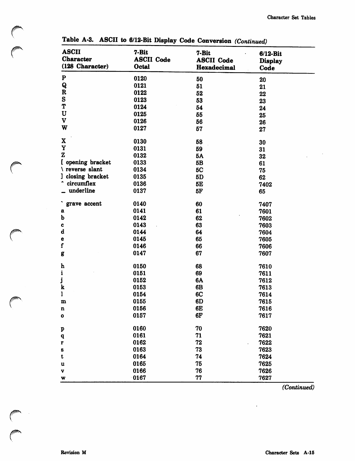
Character Set Tables
Table A-3. ASCII to 6/12-Bit Display Code Conversion (Continued)
ASCII
Character
(128 Character)
7-Bit
ASCII Code
Octal
P
Q
R
S
T
U
V
W
X
Y
Z
[ opening bracket
\ reverse slant
] closing bracket
* circumflex
_ underline
grave accent
h
i
j
k
1
m
n
o
P
q
r
s
t
u
V
w
0120
0121
0122
0123
0124
0125
0126
0127
0130
0131
0132
0133
0134
0135
0136
0137
0140
0141
0142
0143
0144
0145
0146
0147
0150
0151
0152
0153
0154
0155
0156
0157
0160
0161
0162
0163
0164
0165
0166
0167
7-Bit
ASCII Code
Hexadecimal
50
51
52
53
54
55
56
57
58
59
5A
5B
5C
5D
5E
5F
60
61
62
63
64
65
66
67
68
69
6A
6B
6C
6D
6E
6F
70
71
72
73
74
75
76
77
6/12-Bit
Display
Code
20
21
22
23
24
25
26
27
30
31
32
61
75
62
7402
65
7407
7601
7602
7603
7604
7605
7606
7607
7610
7611
7612
7613
7614
7615
7616
7617
7620
7621
7622
7623
7624
7625
7626
7627
(Continued)
0$&s
Revision M Character Sets A-l 5
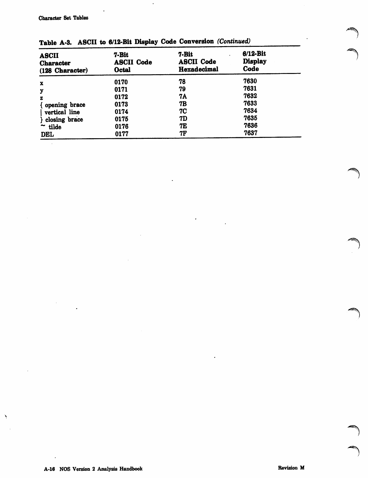
Character Set Tables
Table A-3. ASCII to 6/12-Bit Display Code Conversion (Continued)
ASCII 7-Bit 7-Bit 6/12-Bit
Character ASCII Code ASCII Code Display
(128 Character) Octal Hexadecimal Code
X0170 78 7630
y0171 79 7631
z0172 7A 7632
{ opening brace 0173 7B 7633
| vertical line 0174 7C 7634
} closing brace 0175 7D 7635
- tilde 0176 7E 7636
DEL 0177 7F 7637
-^
A-16 NOS Version 2 Analysis Handbook Revision M
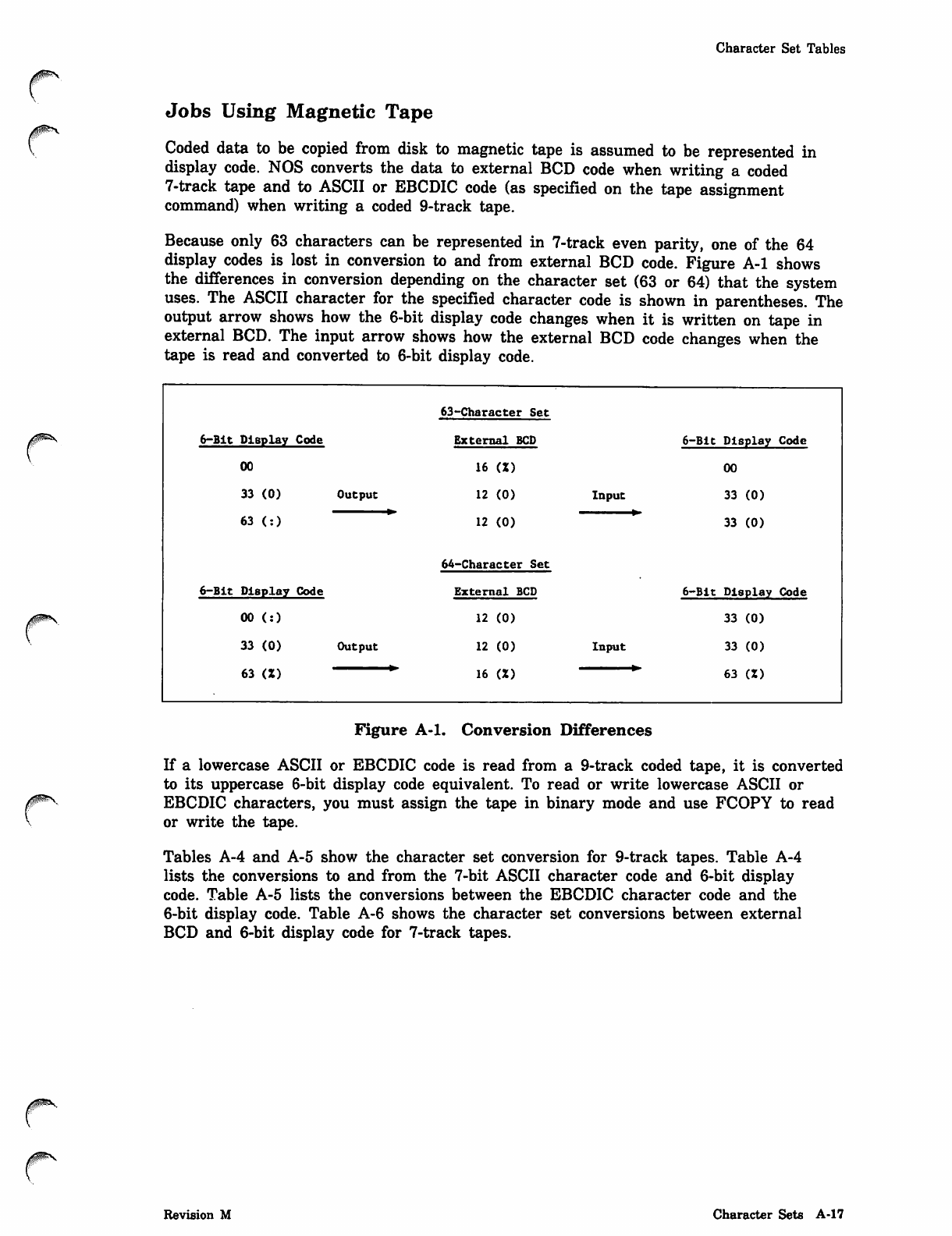
Character Set Tables
Jobs Using Magnetic Tape
Coded data to be copied from disk to magnetic tape is assumed to be represented in
display code. NOS converts the data to external BCD code when writing a coded
7-track tape and to ASCII or EBCDIC code (as specified on the tape assignment
command) when writing a coded 9-track tape.
Because only 63 characters can be represented in 7-track even parity, one of the 64
display codes is lost in conversion to and from external BCD code. Figure A-l shows
the differences in conversion depending on the character set (63 or 64) that the system
uses. The ASCII character for the specified character code is shown in parentheses. The
output arrow shows how the 6-bit display code changes when it is written on tape in
external BCD. The input arrow shows how the external BCD code changes when the
tape is read and converted to 6-bit display code.
/0&S
63-Character Set
6-Bit Display Code External BCD 6-Bit Display Code
00 16 (Z) 00
33 (0) Output 12 (0) Input 33 (0)
63 (:) 12 (0)
64-Character Set
33 (0)
6-Bit Display Code External BCD 6-Bit Display Code
00 (:) 12 (0) 33 (0)
3 3 ( 0 ) O u t p u t 12 (0)
16 (Z)
Input 33 (0)
63 (Z)6 3 ( Z ) ~ ' " " *
Figure A-l. Conversion Differences
If a lowercase ASCII or EBCDIC code is read from a 9-track coded tape, it is converted
to its uppercase 6-bit display code equivalent. To read or write lowercase ASCII or
EBCDIC characters, you must assign the tape in binary mode and use FCOPY to read
or write the tape.
Tables A-4 and A-5 show the character set conversion for 9-track tapes. Table A-4
lists the conversions to and from the 7-bit ASCII character code and 6-bit display
code. Table A-5 lists the conversions between the EBCDIC character code and the
6-bit display code. Table A-6 shows the character set conversions between external
BCD and 6-bit display code for 7-track tapes.
Revision M Character Sets A-17
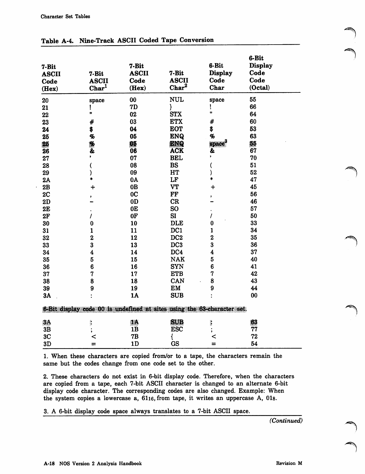
Character Set Tables
Table A-4. Nine-Track A,SCII Coded Tape Conversion
6-Bit
7-Bit 7-Bit 6-Bit Display
ASCII 7-Bit ASCII 7-Bit Display Code
Code ASCII Code ASCII Code Code
(Hex) Char1 (Hex) Char2 Char (Octal)
20 space 00 NUL space 55
21 7D 66
22 ii 02 STX ti 64
23 03 ETX 60
24 04 EOT 53
25 05 ENQ 63
126 05 ;EMQ Bpace3 55
26 06 ACK 67
27 07 BEL 70
28 08 BS 51
29 09 HT 52
2A OA LF 47
2B OB VT 45
2C OC FF 56
2D 0D CR 46
2E 0E SO 57
2F OF SI 50
30 10 DLE 33
31 11 DC1 34
32 12 DC2 35
33 13 DC3 36
34 14 DC4 37
35 15 NAK 40
36 16 SYN 41
37 17 ETB 42
38 18 CAN 43
39 19 EM 44
3A IA SUB 00
iililiij^^ -iii^i^l^^barac^r^sftt
m:J SUB :4
:t 63
3B IB ESC 77
3C 7B 72
3D ID GS 54
/f=^^.
1. When these characters are copied from/or to a tape, the characters remain the
same but the codes change from one code set to the other.
2. These characters do not exist in 6-bit display code. Therefore, when the characters
are copied from a tape, each 7-bit ASCII character is changed to an alternate 6-bit
display code character. The corresponding codes are also changed. Example: When
the system copies a lowercase a, 61i6, from tape, it writes an uppercase A, 01s.
3. A 6-bit display code space always translates to a 7-bit ASCII space.
(Continued)
A-18 NOS Version 2 Analysis Handbook Revision M
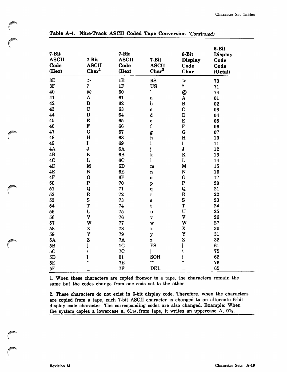
Character Set Tables
r
r
Table A-4. Nine-Track ASCII Coded Tape Conversion (Continued)
6-Bit
7-Bit 7-Bit 6-Bit Display
ASCII 7-Bit ASCII 7-Bit Display Code
Code ASCII Code ASCII Code Code
(Hex) Char1 (Hex) Char2 Char (Octal)
3E IE RS 73
3F IF US 71
40 60 74
41 61 01
42 62 02
43 63 03
44 64 04
45 65 05
46 66 06
47 67 07
48 68 10
49 69 11
4A 6A 12
4B 6B 13
4C 6C 14
4D 6D 15
4E 6E 16
4F 6F 17
50 70 20
51 71 21
52 72 22
53 73 23
54 74 24
55 75 25
56 76 26
57 77 27
58 78 30
59 79 31
5A 7A 32
5B IC FS 61
5C 7C 75
5D 01 SOH 62
5E 7E "• 76
5F 7F DEL 65
1. When these characters are copied from/or to a tape, the characters remain the
same but the codes change from one code set to the other.
2. These characters do not exist in 6-bit display code. Therefore, when the characters
are copied from a tape, each 7-bit ASCII character is changed to an alternate 6-bit
display code character. The corresponding codes are also changed. Example: When
the system copies a lowercase a, 61i6, from tape, it writes an uppercase A, 01s.
/gP>\
Revision M Character Sets A-19
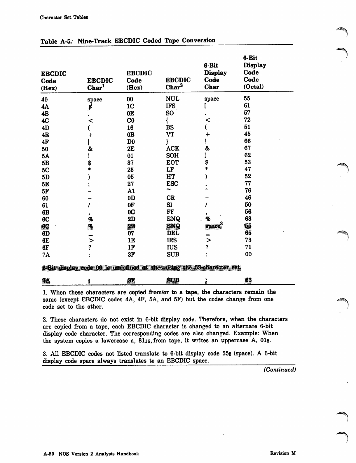
Character Set Tables
Table A-5. Nine-Track EBCDIC Coded Tape Conversion
6-Bit
6-Bit Display
EBCDIC EBCDIC Display Code
Code EBCDIC Code EBCDIC Code Code
(Hex) Char1 (Hex) Char2 Char (Octal)
40 space 00 NUL space 55
4 A t IC IFS 61
4B 0E SO 57
4 C < CO 72
4 D ( 16 BS 51
4 E + 0B VT 45
4 F | DO 66
5 0 & 2E ACK 67
5 A ! 01 SOH 62
5 B $ 37 EOT 53
5 C * 25 LF 47
5 D ) 05 HT 52
5 E ; 27 ESC 77
5F Al 76
60 0D CR 46
6 1 / OF SI 50
6B 0C FF 56
6 C % 2D ENQ . % 63
m m 2D mm ■$$-W$ 55
6D 07 DEL 65
6 E > IE IRS 73
6 F ? IF IUS 71
7A 3F SUB 00
^Bit disp^y code GO is undafi**ed at sites £8*$$ the 63-eharacter mt
i-sisi? s mm. :♦S3
/ * ^ \
1. When these characters are copied from/or to a tape, the characters remain the
same (except EBCDIC codes 4A, 4F, 5A, and 5F) but the codes change from one
code set to the other.
2. These characters do not exist in 6-bit display code. Therefore, when the characters
are copied from a tape, each EBCDIC character is changed to an alternate 6-bit
display code character. The corresponding codes are also changed. Example: When
the system copies a lowercase a, 8116, from tape, it writes an uppercase A, 018.
3. All EBCDIC codes not listed translate to 6-bit display code 55s (space). A 6-bit
display code space always translates to an EBCDIC space.
(Continued)
A-20 NOS Version 2 Analysis Handbook Revision M
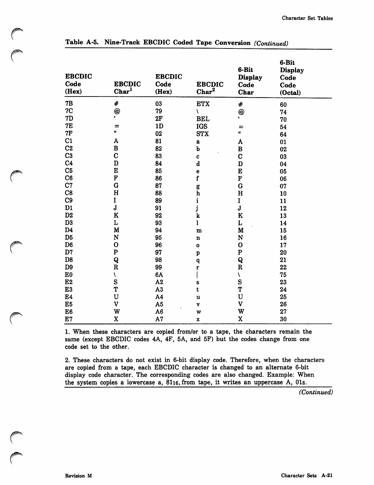
Character Set Tables
r
Table A-5. Nine-Track EBCDIC Coded Tape Conversion (Continued)
6-Bit
6-Bit Display
EBCDIC EBCDIC Display Code
Code EBCDIC Code EBCDIC Code Code
(Hex) Char1 (Hex) Char2 Char (Octal)
7B 03 ETX 60
7C 79 74
7D 2F BEL 70
7E ID IGS 54
7F it 02 STX •i 64
Cl 81 01
C2 82 02
C3 83 03
C4 84 04
C5 85 05
C6 86 06
C7 87 07
C8 88 10
C9 89 11
DI 91 12
D2 92 13
D3 93 14
D4 94 15
D5 95 16
D6 96 17
D7 97 20
D8 98 21
D9 99 22
EO 6A 75
E2 A2 23
E3 A3 24
E4 A4 25
E5 A5 26
E6 A6 27
E7 A7 30
1. When these characters are copied from/or to a tape, the characters remain the
same (except EBCDIC codes 4A, 4F, 5A, and 5F) but the codes change from one
code set to the other.
2. These characters do not exist in 6-bit display code. Therefore, when the characters
are copied from a tape, each EBCDIC character is changed to an alternate 6-bit
display code character. The corresponding codes are also changed. Example: When
the system copies a lowercase a, 81i6,from tape, it writes an uppercase A, 01s.
(Continued)
Revision M Character Sets A-21
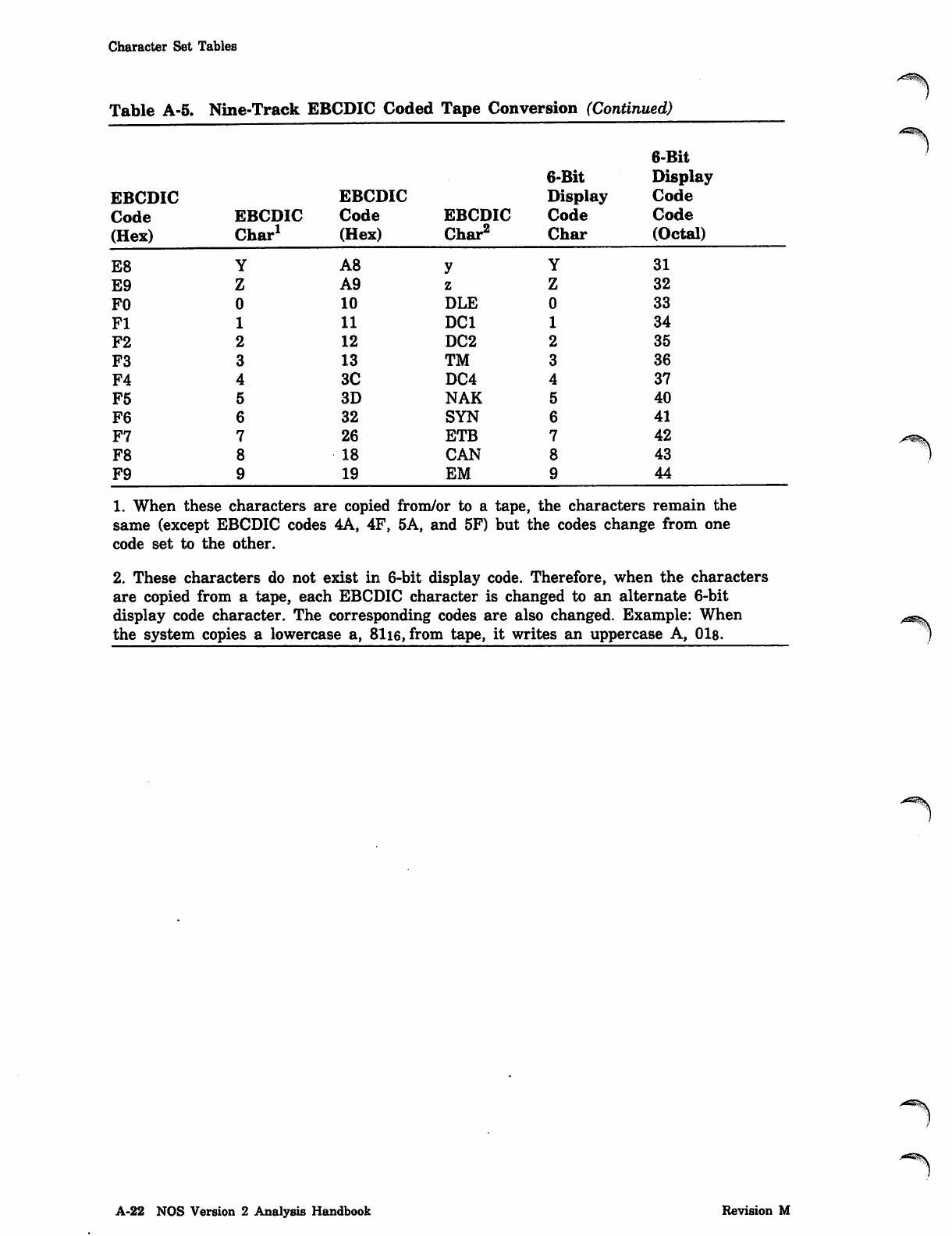
Character Set Tables
Table A-5. Nine-Track EBCDIC Coded Tape Conversion (Continued)
6-Bit
6-Bit Display
EBCDIC EBCDIC Display Code
Code EBCDIC Code EBCDIC Code Code
(Hex) Char1 (Hex) Char2 Char (Octal)
E8 A8 31
E9 A9 32
FO 10 DLE 33
Fl 11 DC1 34
F2 12 DC2 35
F3 13 TM 36
F4 3C DC4 37
F5 3D NAK 40
F6 32 SYN 41
F7 26 ETB 42
F8 18 CAN 43
F9 19 EM 44
1. When these characters are copied from/or to a tape, the characters remain the
same (except EBCDIC codes 4A, 4F, 5A, and 5F) but the codes change from one
code set to the other.
2. These characters do not exist in 6-bit display code. Therefore, when the characters
are copied from a tape, each EBCDIC character is changed to an alternate 6-bit
display code character. The corresponding codes are also changed. Example: When
the system copies a lowercase a, 81i6, from tape, it writes an uppercase A, 01s.
A-22 NOS Version 2 Analysis Handbook Revision M
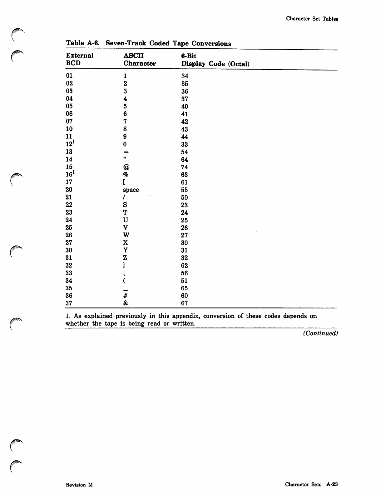
Character Set Tables
/#^\
Table A-6. Seven-Track Coded Tape Conversions
External ASCII 6-Bit
BCD Character Display Code (Octal)
01 34
02 35
03 36
04 37
05 40
06 41
07 42
10 43
11 44
121 33
13 54
14 64
15 74
161 63
17 61
20 space 55
21 50
22 23
23 24
24 25
25 26
26 27
27 30
30 31
31 32
32 62
33 56
34 51
35 «M> 65
36 60
37 67
1. As explained previously in this appendix, conversion of these codes depends on
whether the tape is being read or written.
(Continued)
Revision M Character Sets A-23
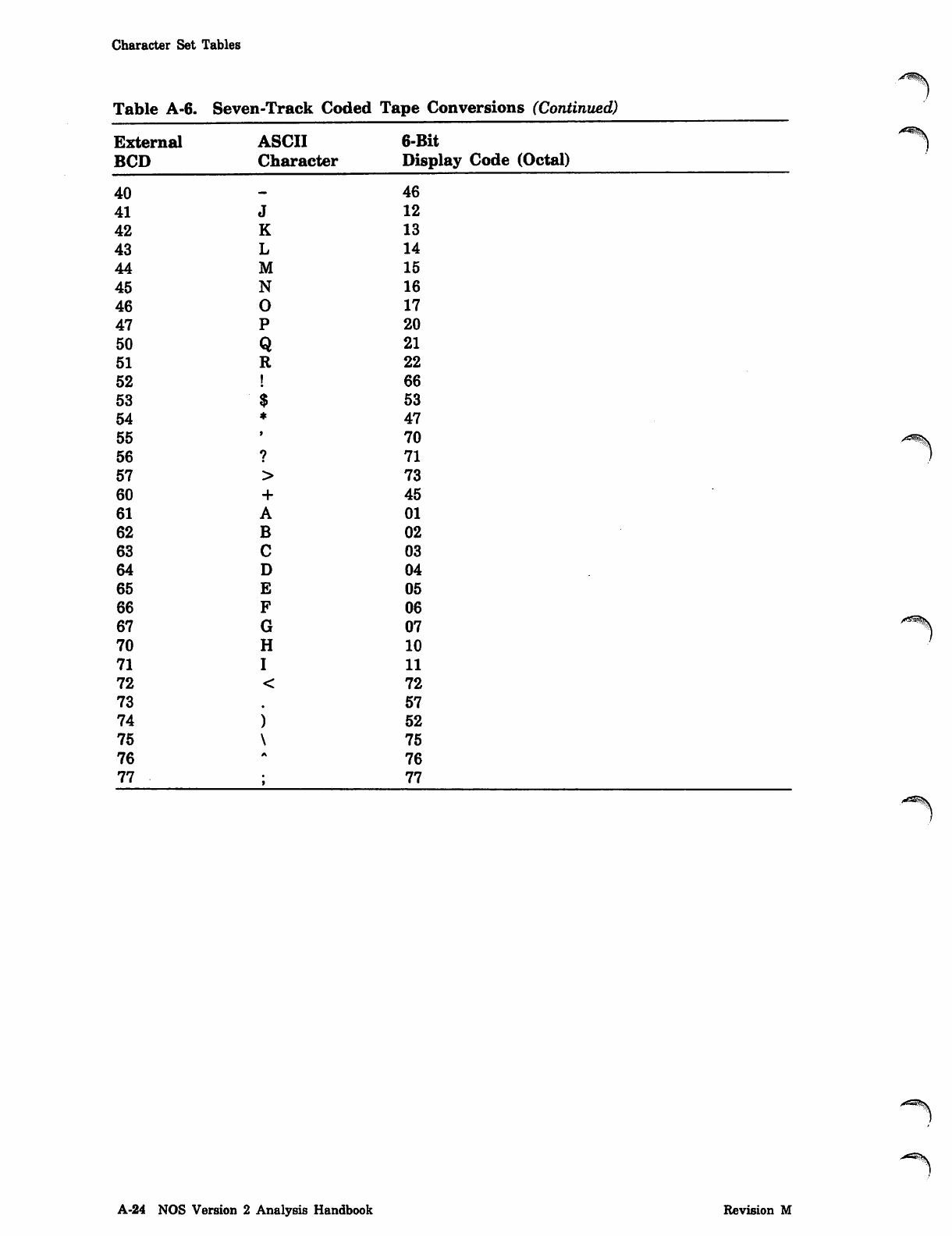
Character Set Tables
Table A-6. Seven-Track Coded Tape Conversions (Continued)
External ASCII 6-Bit
BCD Character Display Code (Octal)
40 46
41 12
42 13
43 14
44 15
45 16
46 17
47 20
50 21
51 22
52 66
53 53
54 47
55 70
56 71
57 73
60 45
61 01
62 02
63 03
64 04
65 05
66 06
67 07
70 10
71 11
72 72
73 57
74 52
75 75
76 76
77 77
A-24 NOS Version 2 Analysis Handbook Revision M
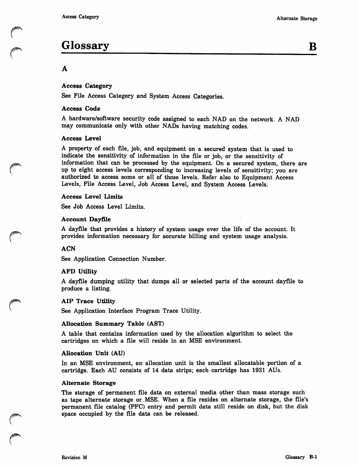
y fi fl ^ ^ L
Access Category Alternate Storage
Glossary B
Access Category
See File Access Category and System Access Categories.
Access Code
A hardware/software security code assigned to each NAD on the network. A NAD
may communicate only with other NADs having matching codes.
Access Level
A property of each file, job, and equipment on a secured system that is used to
indicate the sensitivity of information in the file or job, or the sensitivity of
information that can be processed by the equipment. On a secured system, there are
up to eight access levels corresponding to increasing levels of sensitivity; you are
authorized to access some or all of those levels. Refer also to Equipment Access
Levels, File Access Level, Job Access Level, and System Access Levels.
Access Level Limits
See Job Access Level Limits.
Account Dayfile
A dayfile that provides a history of system usage over the life of the account. It
provides information necessary for accurate billing and system usage analysis.
ACN
See Application Connection Number.
AFD Utility
A dayfile dumping utility that dumps all or selected parts of the account dayfile to
produce a listing.
AIP Trace Utility
See Application Interface Program Trace Utility.
Allocation Summary Table (AST)
A table that contains information used by the allocation algorithm to select the
cartridges on which a file will reside in an MSE environment.
Allocation Unit (AU)
In an MSE environment, an allocation unit is the smallest allocatable portion of a
cartridge. Each AU consists of 14 data strips; each cartridge has 1931 AUs.
Alternate Storage
The storage of permanent file data on external media other than mass storage such
as tape alternate storage or MSE. When a file resides on alternate storage, the file's
permanent file catalog (PFC) entry and permit data still reside on disk, but the disk
space occupied by the file data can be released.
Revision M Glossary B-l
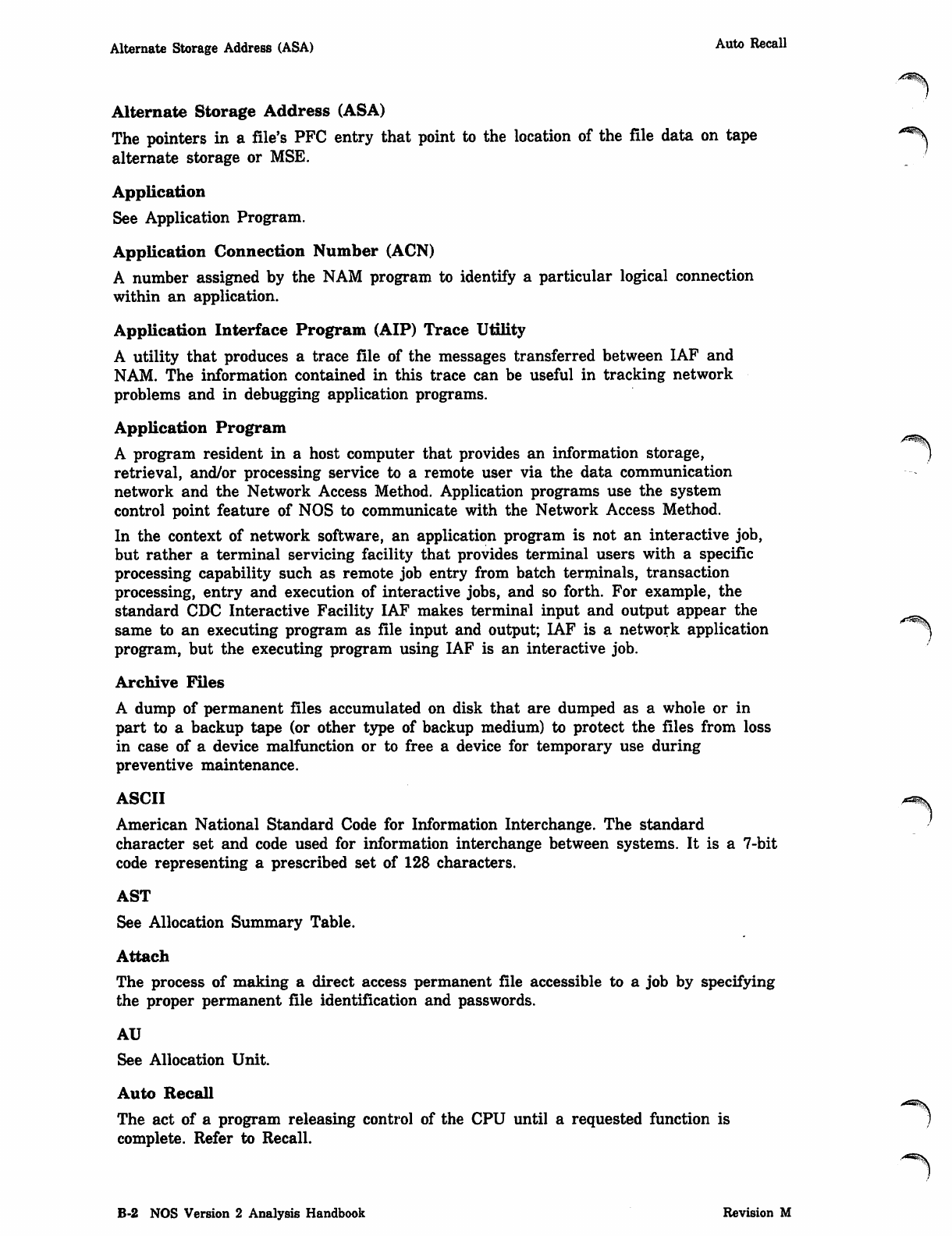
Alternate Storage Address (ASA) Auto Recall
Alternate Storage Address (ASA)
The pointers in a file's PFC entry that point to the location of the file data on tape "^
alternate storage or MSE.
Application
See Application Program.
Application Connection Number (ACN)
A number assigned by the NAM program to identify a particular logical connection
within an application.
Application Interface Program (AIP) Trace Utility
A utility that produces a trace file of the messages transferred between IAF and
NAM. The information contained in this trace can be useful in tracking network
problems and in debugging application programs.
Application Program
A program resident in a host computer that provides an information storage,
retrieval, and/or processing service to a remote user via the data communication
network and the Network Access Method. Application programs use the system
control point feature of NOS to communicate with the Network Access Method.
In the context of network software, an application program is not an interactive job,
but rather a terminal servicing facility that provides terminal users with a specific
processing capability such as remote job entry from batch terminals, transaction
processing, entry and execution of interactive jobs, and so forth. For example, the
standard CDC Interactive Facility IAF makes terminal input and output appear the ^_^^
same to an executing program as file input and output; IAF is a network application ^
program, but the executing program using IAF is an interactive job.
Archive Files
A dump of permanent files accumulated on disk that are dumped as a whole or in
part to a backup tape (or other type of backup medium) to protect the files from loss
in case of a device malfunction or to free a device for temporary use during
preventive maintenance.
ASCII
American National Standard Code for Information Interchange. The standard
character set and code used for information interchange between systems. It is a 7-bit
code representing a prescribed set of 128 characters.
AST
See Allocation Summary Table.
Attach
The process of making a direct access permanent file accessible to a job by specifying
the proper permanent file identification and passwords.
AU
See Allocation Unit.
Auto Recall
The act of a program releasing control of the CPU until a requested function is )
complete. Refer to Recall.
B-2 NOS Version 2 Analysis Handbook Revision M
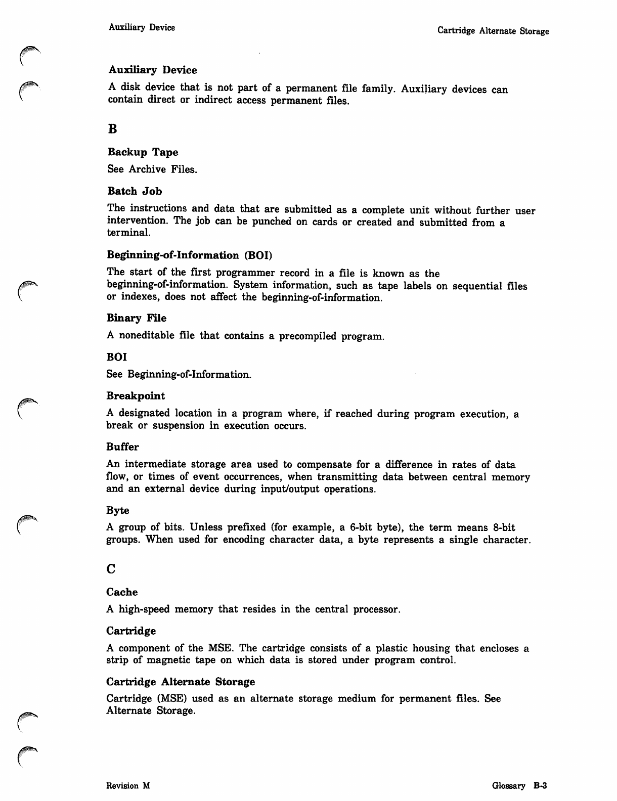
Auxiliary Device Cartridge Alternate Storage
Auxiliary Device
A disk device that is not part of a permanent file family. Auxiliary devices can
contain direct or indirect access permanent files.
B
Backup Tape
See Archive Files.
Batch Job
The instructions and data that are submitted as a complete unit without further user
intervention. The job can be punched on cards or created and submitted from a
terminal.
Beginning-of-information (BOI)
The start of the first programmer record in a file is known as the
r beginning-of-information. System information, such as tape labels on sequential files
or indexes, does not affect the beginning-of-information.
Binary File
A noneditable file that contains a precompiled program.
BOI
See Beginning-of-information.
Breakpoint
A designated location in a program where, if reached during program execution, a
break or suspension in execution occurs.
Buffer
An intermediate storage area used to compensate for a difference in rates of data
flow, or times of event occurrences, when transmitting data between central memory
and an external device during input/output operations.
Byte
A group of bits. Unless prefixed (for example, a 6-bit byte), the term means 8-bit
groups. When used for encoding character data, a byte represents a single character.
c
Cache
A high-speed memory that resides in the central processor.
Cartridge
A component of the MSE. The cartridge consists of a plastic housing that encloses a
strip of magnetic tape on which data is stored under program control.
0*ms
Cartridge Alternate Storage
Cartridge (MSE) used as an alternate storage medium for permanent files. See
Alternate Storage.
Revision M Glossary B-3
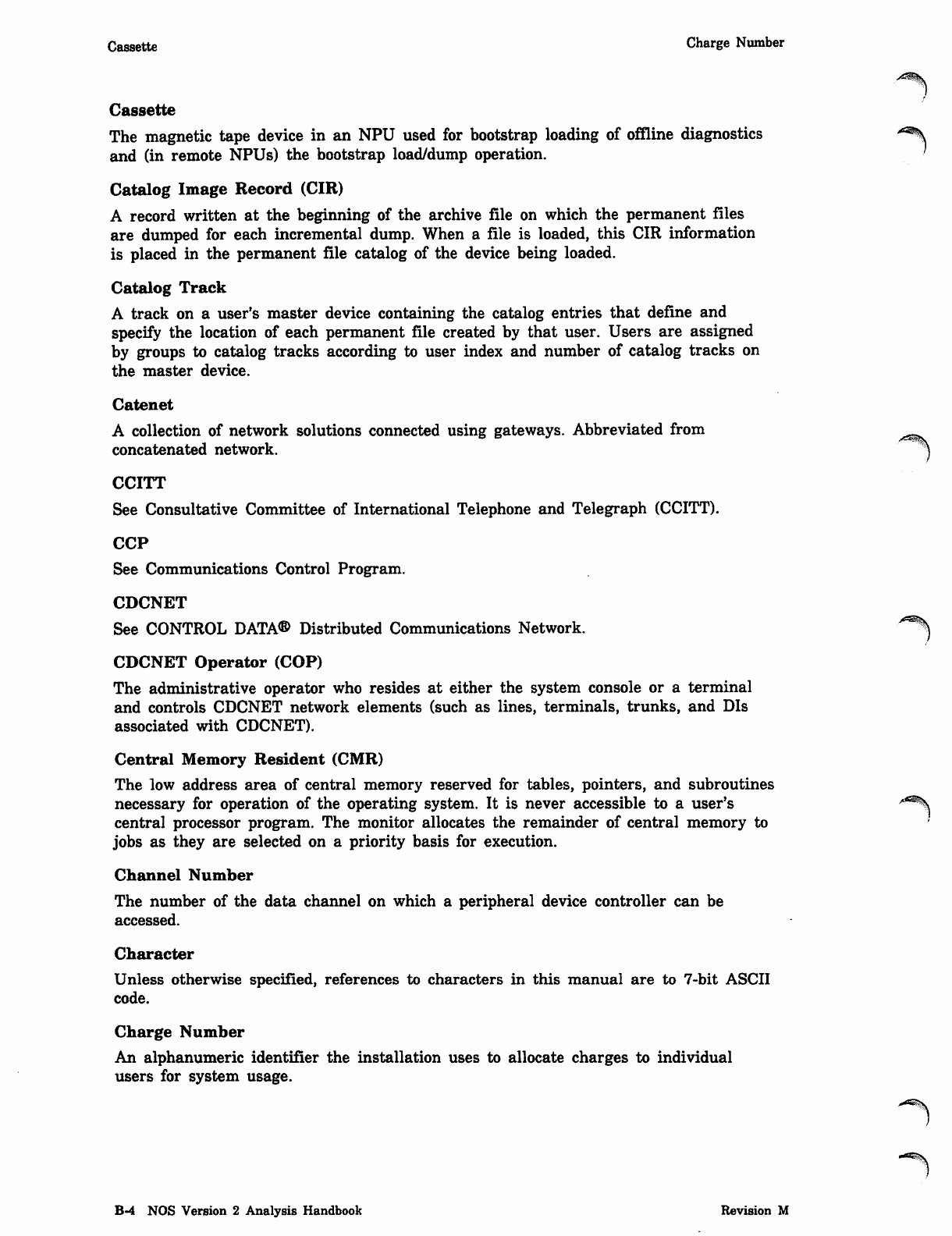
Cassette Charge Number
Cassette
The magnetic tape device in an NPU used for bootstrap loading of offline diagnostics
and (in remote NPUs) the bootstrap load/dump operation.
Catalog Image Record (CIR)
A record written at the beginning of the archive file on which the permanent files
are dumped for each incremental dump. When a file is loaded, this CIR information
is placed in the permanent file catalog of the device being loaded.
Catalog Track
A track on a user's master device containing the catalog entries that define and
specify the location of each permanent file created by that user. Users are assigned
by groups to catalog tracks according to user index and number of catalog tracks on
the master device.
Catenet
A collection of network solutions connected using gateways. Abbreviated from ^^
concatenated network. /^^\
CCITT
See Consultative Committee of International Telephone and Telegraph (CCITT).
CCP
See Communications Control Program.
CDCNET
See CONTROL DATA® Distributed Communications Network.
CDCNET Operator (COP)
The administrative operator who resides at either the system console or a terminal
and controls CDCNET network elements (such as lines, terminals, trunks, and DIs
associated with CDCNET).
Central Memory Resident (CMR)
The low address area of central memory reserved for tables, pointers, and subroutines
necessary for operation of the operating system. It is never accessible to a user's /*s\
central processor program. The monitor allocates the remainder of central memory to
jobs as they are selected on a priority basis for execution.
Channel Number
The number of the data channel on which a peripheral device controller can be
accessed.
Character
Unless otherwise specified, references to characters in this manual are to 7-bit ASCII
code.
Charge Number
An alphanumeric identifier the installation uses to allocate charges to individual
users for system usage.
B-4 NOS Version 2 Analysis Handbook Revision M
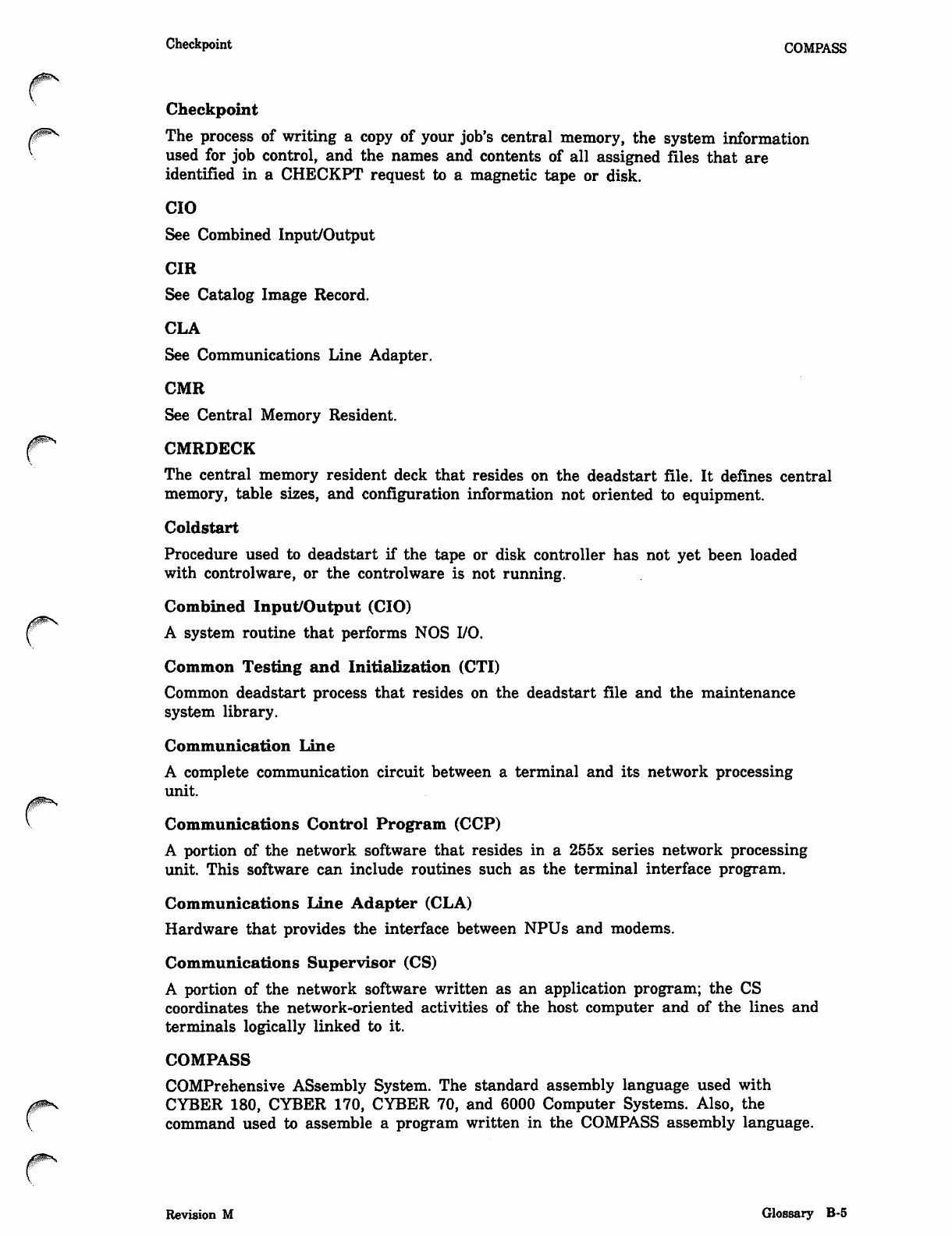
A ^ S
0 ^ s
Checkpoint COMPASS
Checkpoint
The process of writing a copy of your job's central memory, the system information
used for job control, and the names and contents of all assigned files that are
identified in a CHECKPT request to a magnetic tape or disk.
CIO
See Combined Input/Output
CIR
See Catalog Image Record.
CLA
See Communications Line Adapter.
CMR
See Central Memory Resident.
CMRDECK
The central memory resident deck that resides on the deadstart file. It defines central
memory, table sizes, and configuration information not oriented to equipment.
Coldstart
Procedure used to deadstart if the tape or disk controller has not yet been loaded
with controlware, or the controlware is not running.
Combined Input/Output (CIO)
A system routine that performs NOS I/O.
Common Testing and Initialization (CTI)
Common deadstart process that resides on the deadstart file and the maintenance
system library.
Communication Line
A complete communication circuit between a terminal and its network processing
unit.
Communications Control Program (CCP)
A portion of the network software that resides in a 255x series network processing
unit. This software can include routines such as the terminal interface program.
Communications Line Adapter (CLA)
Hardware that provides the interface between NPUs and modems.
Communications Supervisor (CS)
A portion of the network software written as an application program; the CS
coordinates the network-oriented activities of the host computer and of the lines and
terminals logically linked to it.
COMPASS
COMPrehensive ASsembly System. The standard assembly language used with
CYBER 180, CYBER 170, CYBER 70, and 6000 Computer Systems. Also, the
command used to assemble a program written in the COMPASS assembly language.
Revision M Glossary B-5
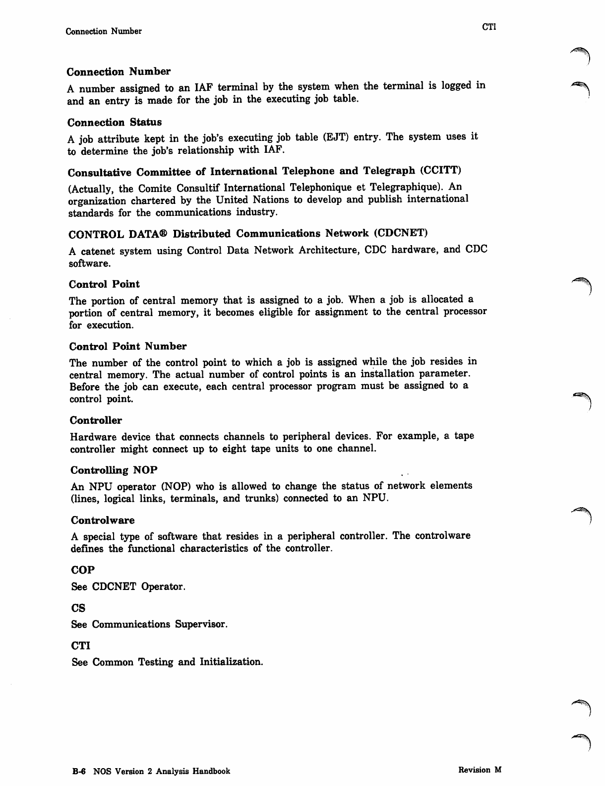
CTI
Connection Number
Connection Number
A number assigned to an IAF terminal by the system when the terminal is logged in
and an entry is made for the job in the executing job table.
Connection Status
A job attribute kept in the job's executing job table (EJT) entry. The system uses it
to determine the job's relationship with IAF.
Consultative Committee of International Telephone and Telegraph (CCITT)
(Actually, the Comite Consultif International Telephonique et Telegraphique). An
organization chartered by the United Nations to develop and publish international
standards for the communications industry.
CONTROL DATA® Distributed Communications Network (CDCNET)
A catenet system using Control Data Network Architecture, CDC hardware, and CDC
software.
Control Point
The portion of central memory that is assigned to a job. When a job is allocated a
portion of central memory, it becomes eligible for assignment to the central processor
for execution.
Control Point Number
The number of the control point to which a job is assigned while the job resides in
central memory. The actual number of control points is an installation parameter.
Before the job can execute, each central processor program must be assigned to a
control point.
Controller
Hardware device that connects channels to peripheral devices. For example, a tape
controller might connect up to eight tape units to one channel.
Controlling NOP
An NPU operator (NOP) who is allowed to change the status of network elements
(lines, logical links, terminals, and trunks) connected to an NPU.
Controlware
A special type of software that resides in a peripheral controller. The controlware
defines the functional characteristics of the controller.
COP
See CDCNET Operator.
CS
See Communications Supervisor.
CTI
See Common Testing and Initialization.
s^s.
B-6 NOS Version 2 Analysis Handbook Revision M
0$$S
DAT Detached Job
D
DAT
See Device Access Table.
Data Channel
One of the 9 to 24 channels (12-bit) by which information passes between the
peripheral processors and peripheral devices. Refer to Channel Number.
Data Recording Drive (DRD)
A component of the 7991 Storage Module. The DRD reads data from and writes data
to the cartridges.
Dayfile
A chronological file created during job execution that forms a permanent accounting
and job history record. Dayfile messages are generated by operator action or when
some commands are processed. A copy of the dayfile is printed with the output for
each job. The user must explicitly request it in an interactive job.
DDP
The distributive data path.
Deadstart
The process of initializing the system by loading the operating system library
programs and any of the product set from magnetic tape or disk. Deadstart recovery
is reinitialization after system failure.
Deadstart Sequencing
The execution of a selected set of commands before normal system job scheduling is
enabled.
Debug Log File Processor (DLFP)
A processor that analyzes trace files produced by the application interface program
trace utility.
Destage Dump Tapes
Tapes that contain files that were destaged from disk using the PFDUMP utility with
the DT parameter specified.
Destaging
The process of creating an alternate storage copy of a file on tape alternate storage
or MSE. Files are destaged to tape alternate storage when the site executes PFDUMP
with the DT parameter specified. Files are destaged to MSE when the site executes
SSMOVE with the appropriate parameters specified.
Detached Job
An interactive service class job removed from control of the Interactive Subsystem. It
may or may not continue to execute, depending on the presence of commands in the
command buffer or an active job step. Control is regained by recovering the EJT
entry for the job.
Revision M Glossary B-7
Device Access Table (DAT) Disabled Job
Device Access Table (DAT)
A table that contains the logical description (family name/pack name and device
number) of each disk device (shared or nonshared) that is accessible by any machine
in a linked shared device multimainframe complex.
Device Index Table (DIT)
A table that is used to determine device usage in an independent shared device
multimainframe complex.
Device Interface (DI)
CDCNET hardware for open system interconnection. The device interface houses
processor boards in configurations that permit a network of various other data
processing equipment.
Device Mask
An 8-bit quantity that identifies the group of users who have the particular device as
their master device; that is, it identifies the device that contains their file catalogs,
all their indirect access files, and possibly some or all of their direct access files.
DFD Utility
A dayfile dumping utility that dumps all or selected parts of the system dayfile to
produce a listing.
DFLIST Utility
A utility that generates a printer listing of all permanent files created by the
DFTERM utility.
DFTERM Utility
A utility that terminates an active or inactive dayfile and retains it as a direct
access permanent file for later use.
DI
See Device Interface.
Diagnostic Operator (DOP)
An NPU operator who resides at a terminal and has permission only to check status
and test the network.
Direct Access File
A NOS permanent file that can be attached to the your job. All changes to this file
are made on the file itself rather than a temporary copy of the file (compare with
Indirect Access File).
DIS (Job Display)
A system peripheral processor program similar to the system display (DSD) that
provides communication between a job in central memory and the operator at the
console, and permits the operator to control execution of the program through the
console keyboard.
Disabled Job
An interactive service class job temporarily rolled out due to user break processing or
encountering the end of its command stream. The job scheduler ignores disabled jobs.
/*a*%
B-8 NOS Version 2 Analysis Handbook Revision M
0ms
r
Display Code EJT
Display Code
A 6-bit character code set that represents alphanumeric and special characters.
Disposition Code
A 2-character mnemonic indicating the destination queue and format for processing a
file named on a ROUTE function.
DIT
See Device Index Table.
DLFP
See Debug Log File Processor.
DMPNAD
See Dump NAD Memory.
DOP
See Diagnostic Operator.
Downline
The direction of output flow, from host to terminal.
DRD
See Data Recording Drive.
DSD (System Display)
The operating system program that provides communication between the operator and
the system by accepting control information typed on the console keyboard and by
displaying information pertinent to all jobs known to the system. DSD is permanently
assigned to peripheral processor 1.
DSDI Utility
A deadstart dump interpreter utility that is called by a batch command to convert
selected portions of the binary information on an express deadstart dump file into
reports to be listed.
Dump NAD Memory (DMPNAD)
A utility that reads the NAD memory and formats the data into an output file.
E
ECS .
See Extended Core Storage.
EDD FUe
See Express Deadstart Dump File.
EDD Utility
See Express Deadstart Dump Utility.
EJT
See Executing Job Table.
Revision M Glossary B-9
EJT Ordinal Equipment Access Levels
EJT Ordinal
An index into the executing job table (EJT). It uniquely identifies an EJT entry. The ^^\
acceptable range is from 0001 to 4095.
ELD Utility
A dayfile dumping utility that dumps all or selected parts of the error log dayfile to
produce a listing.
End-of-Chain Flag (EOC)
In an MSE environment, EOC is a flag in the 7990 catalog that identifies the last
volume in a chain of allocated AUs.
End-of-File (EOF)
A boundary within a sequential file, but not necessarily the end of a file that can be
referenced by name. The actual end of a named file is defined by EOI. For labeled
tape, EOF and EOI (denoted by the EOFl label) are the same. For multifile tape
files, EOF and EOI do not correspond. In the product set manuals, an end-of-file is ^^
also referred to as an end-of-partition. *^i
End-of-Information (EOI)
The end of data on a file. Information appearing after this point is not considered
part of file data. In card decks, a card with a 6/7/8/9 multiple punch in column 1. On
mass storage devices, the position of the last written data. On labeled tape, it is the
EOFl label. CYBER Record Manager defines end-of-information in terms of file
residency and organization.
End-of-Record (EOR)
An indicator that marks the end of a logical record. Also referred to as end-of-section.
Entry Point
A location within a program or procedure that can be referenced from other
programs. Each entry point has a unique name with which it is associated.
EOC
See End-of-Chain Flag.
EOF
See End-of-File.
EOI
See End-of-Information.
EOR
See End-of-Record.
EQPDECK
The equipment description deck used during deadstart to define the system equipment
configuration.
Equipment Access Levels
A range of access levels specified for each equipment on a secured system. In order
for a file to be stored or output on a given equipment, the file's access level must be
within the equipment access levels for that equipment.
B-10 NOS Version 2 Analysis Handbook Revision M
0$$*s
Equipment Number Extended Core Storage (ECS)
Equipment Number
A number from 0 to 7 that identifies the setting on a peripheral device controller.
Equipment Status Table (EST)
A central memory resident table listing all the defined equipments, parameters
affecting their operation, and the status of the equipments.
ESM
See Extended Semiconductor Memory.
EST
See Equipment Status Table.
EST Ordinal
The number designating the position of an entry within the equipment status table
(EST) established at each installation. Devices are identified in operator commands by
EST ordinals. The EST ordinal is sometimes referred to as equipment number.
Ethernet
A baseband local area network protocol developed by the XEROX, Intel, and Digital
Equipment Corporations. CDCNET is an Ethernet-compatible network.
Exchange Package
A table that contains information used during job execution. It is printed as part of
the output when a job aborts.
Executing Job Table (EJT)
A central memory resident table that contains a 4-word entry for all executing jobs
including interactive service class jobs. It is used to control jobs that are executing at
a control point and jobs that are rolled out. Every executing job in the system has an
EJT entry.
Execution
An input job is in execution after it is selected by the operating system and assigned
to a control point. A job remains in execution until terminated, but it can be
temporarily swapped or rolled out by the operating system.
Express Deadstart Dump (EDD) File
A file that is generated on magnetic tape by the express deadstart dump utility. This
file contains a dump of memory, executing exchange packages, hardware registers,
and controller memory.
Express Deadstart Dump (EDD) Utility
A utility that may be run at deadstart time after a system malfunction has occurred.
It generates the express deadstart dump file on magnetic tape.
Extended Core Storage (ECS)
A type of extended memory that is an option available for 6000 Computer Systems,
CYBER 70 Computer Systems, CYBER 170 Computer Systems (except model 176),
and CYBER 180 Computer Systems. The maximum size of ECS is two million words.
See Extended Memory.
Revision M Glossary B-ll
Extended Memory (EM) FET
Extended Memory (EM)
An additional portion of memory that is available as an option. This memory can be *«%
used for program and data storage, but not for program execution. Special hardware J
instructions exist for transferring data between central memory and extended
memory. Extended memory consists of either extended core storage (ECS), extended
semiconductor memory (ESM), large central memory extended (LCME), or unified
extended memory (UEM).
Extended Memory File Space
The portion of extended memory that is defined as a mass storage device.
Extended Memory I/O Buffers
The portion of extended memory that is used for buffering I/O data to and from
disks. Disks requiring I/O buffers are: 819, 885-42, 887, 895, and 9853.
Extended Semiconductor Memory (ESM)
A type of extended memory that is an option available for 6000 Computer Systems, ^^
CYBER 70 Computer Systems, CYBER 170 Computer Systems (except model 176), ^
and CYBER 180 Computer Systems. The maximum size of ESM is 16 million words.
See Extended Memory.
Facility Interface Program (FIP)
A program consisting of routines and buffers that are loaded into each application
program's field length. This program is the interface between the application program
and RHF.
Family Device
A mass storage permanent file device associated with a specific system. A family may
consist of from 1 to 63 logical devices. Normally, a system runs with one family of
permanent file devices available. However, additional families may be introduced
during normal operation. This enables users associated with the additional families to
access their permanent files via the alternate family.
Family Name
Name of the permanent file storage device or set of devices on which all of a user's
permanent files are stored. When a user requests a permanent file, the system looks
for it on this family (group) of devices. Usually a system has only one family of
permanent file devices, but it is possible to have alternate families in the system. At
login, the user may have to specify which family he/she is using. A user gets a
family name from his/her employer, instructor, or computer center personnel.
Family Ordinal Table (FOT)
A table that maintains the relationship between family ordinals and family names.
FCT
See File and Cartridge Table.
FET
See File Environment Table.
B-12 NOS Version 2 Analysis Handbook Revision M
Field Length FIp
Field Length
The area in central memory allocated to a particular job; the only part of central
memory that a job can directly access. Also the number of central memory words
required to process a job.
File
A collection of information referred to by a file name (from 1 to 7 alphanumeric
characters). You can create a file at the terminal or retrieve a file from permanent
file storage for use during a terminal session.
File Access Category
A property of a permanent file used by the creator of the file on a secured system to
restrict access of the file to a particular group of users. A secured system supports up
to 32 access categories, and a user is authorized to use some, all, or none of those
categories. Refer also to System Access Categories.
File Access Level
A property of each file on a secured system used to indicate the sensitivity of
information contained on the file. A file is assigned the current job access level by
default when it is created or stored; the file creator may specify any access level for
that file that is within the set of access levels valid for the job, the system, the file
creator, and (for interactive jobs) the communication line to the host mainframe. If a
user accesses a file on a secured system, that user must be validated for the access
level of the file. Refer also to Access Level, Job Access Level, and Job Access Level
Limits.
File and Cartridge Table (FCT)
Table that has an entry for each cubicle assigned to the subfamily from a given SM.
File Category
Each permanent file is assigned a category of private, semiprivate, or public.
File Count
A maximum number of permanent files allowed each user.
File Environment Table (FET)
A table within a program's field length through which the program communicates
with operating system input/output routines. One FET exists for each file in use by
the program.
File Name Table (FNT)
A system-managed table that contains the local file name, the file type, and other job
control information. All active files in the system have an FNT entry.
File Status Table (FST)
A system-managed table that contains information pertaining to the file's location in
mass storage and other job control information. Each active file in the system has an
FST entry. See also File Name Table.
FIP
See Facility Interface Program.
Revision M Glossary B-13
First Level Peripheral Processor (FLPP) H0P
First Level Peripheral Processor (FLPP)
The processor that is connected directly to the CYBER 170 Model 176 mainframe and ^
operates synchronously with the mainframe.
FLPP
See First Level Peripheral Processor.
FNT
See File Name Table.
Forms Code
An attribute of output files and output devices. The user can specify special forms
required for output, and then mount the special forms and use the FORM command
to let the system process his/her output.
FOT
See Family Ordinal Table.
FST
See File Status Table.
Function Processor
A system CPU or PP program that the user can call by placing a request in location
RA+1. Function processors perform input/output, local and permanent file
manipulations, and so on.
H
Hardware Initialization and Verification Software (HIVS)
The software package that assists CTI during deadstart and provides deadstart
confidence-level testing (HVS).
Hardware Verification Sequence (HVS)
HVS is a member of HIVS. It tests the ability of memory to hold patterns of data
and execute instructions. The user can choose to test central memory, extended ^g-
memory, PP memory, and central processor memory. j
Head-of-Chain Flag (HOC)
In an MSE environment, HOC is a flag in the 7990 catalog that identifies the first
volume in a chain of allocated AUs.
Header
A word or set of words at the beginning of a block, record, file, or buffer that
contains control information for that unit of data.
HIVS
See Hardware Initialization and Verification Software.
HOC
See Head-of-Chain Flag.
HOP
See Host Operator.
B-14 NOS Version 2 Analysis Handbook Revision M
Host Interactive Transfer Facility (ITF)
Host
The computer that controls a network, executes the application programs, and
processes network messages.
Host Operator (HOP)
The administrative operator who resides at the system console, initiates NAM, and
controls NPUs and network related host elements.
HVS
See Hardware Verification Sequence.
I
IAF
See Interactive Facility.
Inactive Queued File Table (IQFT)
A table of file entries that has been removed from the queued file table. An IQFT
file is on each mass storage device on which one or more inactive queued files reside.
Incremental Dump
An incremental dump copies those permanent files modified after a specified date.
Each incremental dump writes a catalog image record at the beginning of the archive
file on which the permanent files are dumped.
Incremental Load
An incremental load builds up an accumulation of the most recently modified versions
of the files extracted from the archive files for loading. A series of archive files is
read in reverse order of creation. The CIR is read and checked against the archive
files. If a file matches an entry on the CIR, that file is a candidate for loading.
Indirect Access File
A NOS permanent file that you access by making a temporary copy of the file (GET
or OLD command). You create or alter it by saving or substituting the contents of an
existing temporary file (REPLACE or SAVE command).
Input File
The system-defined file that contains the entire job the user submits for processing. It
is also known as the job file.
Input/Output Unit (IOU)
A collection of all PPs, PP channels, and related hardware for models 865 and 875
and CYBER 180-class machines.
Interactive Facility (IAF)
An application that provides a terminal operator with interactive processing
capability. The Interactive Facility makes terminal input/output and file input/output
appear the same to an executing program.
Interactive Transfer Facility (ITF)
f^ A network application that allows the user to connect an interactive terminal to a
remote CYBER 200 computer system linked to a host mainframe by a loosely coupled
network.
Revision M Glossary B-15
IOU LCN
IOU
See Input/Output Unit. ^
IQFT
See Inactive Queued File Table.
ITF
See Interactive Transfer Facility.
Job Access Level
On a secured system, each job has an access level. This is the default access level
that is assigned to files that are created or stored in the job. A job's initial access
level is the lower access level limit for the job. The job's access level is automatically
raised to the access level of any file from which information is read. The user can
also change the job access level. Refer also to Job Access Level Limits. s*ms
Job Access Level Limits
An upper limit and a lower limit that determine the range of access levels that are
valid for a particular job on a secured system. All files used in a given job must
have an access level within the job's access level limits.
Job Sequence Name (JSN)
The unique, system-defined name assigned to every executing job or queued file. The
JSN is a string of four alphabetic characters.
Job Status
A job attribute kept in the job's executing job table (EJT) entry. It is used by the
system to determine if a job is rolled in or rolled out. If the job is rolled out, job
status indicates why it was rolled out.
JSN
See Job Sequence Name.
LAN
See Local Area Network.
Large Central Memory Extended (LCME)
A type of extended memory that is an option available for model 176. Refer to
Extended Memory.
LCF
See Local Configuration File.
LCME
See Large Central Memory Extended.
LCN
See Loosely Coupled Network.
B-16 NOS Version 2 Analysis Handbook Revision M
A^ms
LDLIST Utility ^ NAD
LDLIST Utility
A utility that generates a printer listing of queued files present on a dump tape
produced by the QDUMP utility.
LFG
See Load File Generator.
LID
See Logical Identifier.
LISTPPM Utility
A PIP dump analyzer program that converts all available PIP dump binary records
on th PIP memory dump file into a report to be listed in byte format.
Load File Generator (LFG)
A utility program that reformats communications control program files for subsequent
use by the network supervisor of NAM to load network processing units.
Load Point
Metallic strip marking the beginning of the recordable portion of a magnetic tape.
Data, including labels, is written after the load point. A rewind positions a single file
volume to the load point.
Load Sequence
A sequence of load operations that encompasses all of the loader's processing from the
time that nothing is loaded until the time execution begins. It includes initialization,
specification of specified loader requests, and completion of load.
Local Area Network (LAN)
A privately owned network that interconnects data processing equipment to provide
high-speed communications. It allows users and services to exchange messages and
share resources.
Local Batch Job
A batch job submitted at the central computer site through a card reader or terminal.
Local Configuration File (LCF)
A file in the host computer system containing information on the logical makeup of
the communication elements of the host. The file contains a list of the application
programs available for execution in the host computer, and the users that can access
it. This is a NOS direct access permanent file.
Local File
Any file that is currently associated with a job. Local files include all temporary files
and attached direct access files.
Local File Name
The file name assigned to a file while it is local (assigned) to a job. The name is
contained in the local file name table.
Local NAD
A 380-170 NAD connected to the host mainframe using a channel and configured in
the EST.
Revision M Glossary B-17
Local NPU MAP
Local NPU
An NPU that is connected to the host via a coupler. A local NPU always contains a
host interface program for processing block protocol transfers across the host/local
NPU interface.
Logical Identifier (LID)
A 3-character alphanumeric string used to identify a particular mainframe. LIDs are
identified by the user's site.
Loosely Coupled Network (LCN)
A network of physically connected computer systems. The LCN environment allows
jobs, data files, and messages to be transmitted from one computer system to another.
M
Machine Identification (MID)
The identifier that associates a specific machine with its access to a shared device.
Machine Recovery Table (MRT)
A table that provides the information needed to recover the mass storage space and
interlocks of a machine that shares a mass storage device.
Machine Recovery Utility (MREC)
A utility that clears interlocks held by the machine to be deadstarted that have not
been cleared by CPUMTR. It also recovers mass storage space on a shared device
that is currently not accessible because of a machine interruption.
Macro
A sequence of source statements that is saved and then assembled whenever needed
through a macro call.
Mainframe Device Interface (MDI)
A device interface that is configured to connect a CYBER mainframe to Ethernet.
Mainframe to Terminal Interface (MTI)
A terminal interface that is configured to connect a CYBER mainframe to a terminal
for support of terminal-to-network communications.
MAINLOG Utility
A dayfile dumping utility that dumps all or selected parts of the binary maintenance
log to produce an output file in binary format.
Maintenance Logging Transfer Utility (MLTF)
A utility that controls logging NAD error logs into the binary maintenance log.
Maintenance Register
A hardware register used in error detection, logging, and recovery procedures.
Maintenance registers are used on models 865 and 875 instead of status/control
registers. Refer to Status/Control (S/C) Register.
MAP
The Matrix Algorithm Processor.
B-18 NOS Version 2 Analysis Handbook Revision M
A<5$s
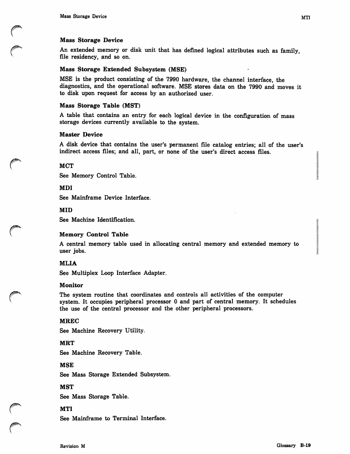
Mass Storage Device MTI
Mass Storage Device
^** An extended memory or disk unit that has defined logical attributes such as family,
file residency, and so on.
Mass Storage Extended Subsystem (MSE)
MSE is the product consisting of the 7990 hardware, the channel interface, the
diagnostics, and the operational software. MSE stores data on the 7990 and moves it
to disk upon request for access by an authorized user.
Mass Storage Table (MST)
A table that contains an entry for each logical device in the configuration of mass
storage devices currently available to the system.
Master Device
A disk device that contains the user's permanent file catalog entries; all of the user's
indirect access files; and all, part, or none of the user's direct access files.
MCT
See Memory Control Table.
MDI
See Mainframe Device Interface.
MID
See Machine Identification.
Memory Control Table
A central memory table used in allocating central memory and extended memory to
user jobs.
MLIA
See Multiplex Loop Interface Adapter.
Monitor
The system routine that coordinates and controls all activities of the computer
system. It occupies peripheral processor 0 and part of central memory. It schedules
the use of the central processor and the other peripheral processors.
MREC
See Machine Recovery Utility.
MRT
See Machine Recovery Table.
MSE
See Mass Storage Extended Subsystem.
MST
See Mass Storage Table.
MTI
See Mainframe to Terminal Interface.
Revision M Glossary B-19
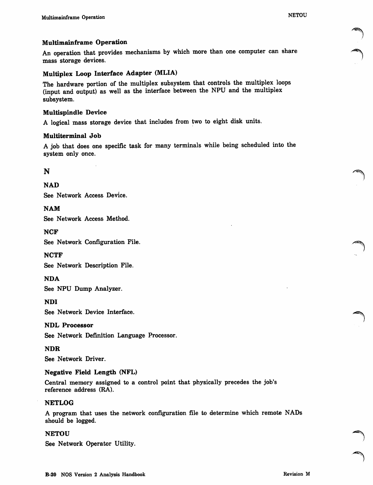
Multimainframe Operation NETOU
Multimainframe Operation
An operation that provides mechanisms by which more than one computer can share a^\
mass storage devices.
Multiplex Loop Interface Adapter (MLIA)
The hardware portion of the multiplex subsystem that controls the multiplex loops
(input and output) as well as the interface between the NPU and the multiplex
subsystem.
Multispindle Device
A logical mass storage device that includes from two to eight disk units.
Multiterminal Job
A job that does one specific task for many terminals while being scheduled into the
system only once.
N s * % .
NAD
See Network Access Device.
NAM
See Network Access Method.
NCF
See Network Configuration File. r*%.
NCTF
See Network Description File.
NDA
See NPU Dump Analyzer.
NDI
See Network Device Interface.
NDL Processor
See Network Definition Language Processor.
NDR
See Network Driver.
Negative Field Length (NFL)
Central memory assigned to a control point that physically precedes the job's
reference address (RA).
NETLOG
A program that uses the network configuration file to determine which remote NADs
should be logged.
NETOU
See Network Operator Utility.
B-20 NOS Version 2 Analysis Handbook Revision M
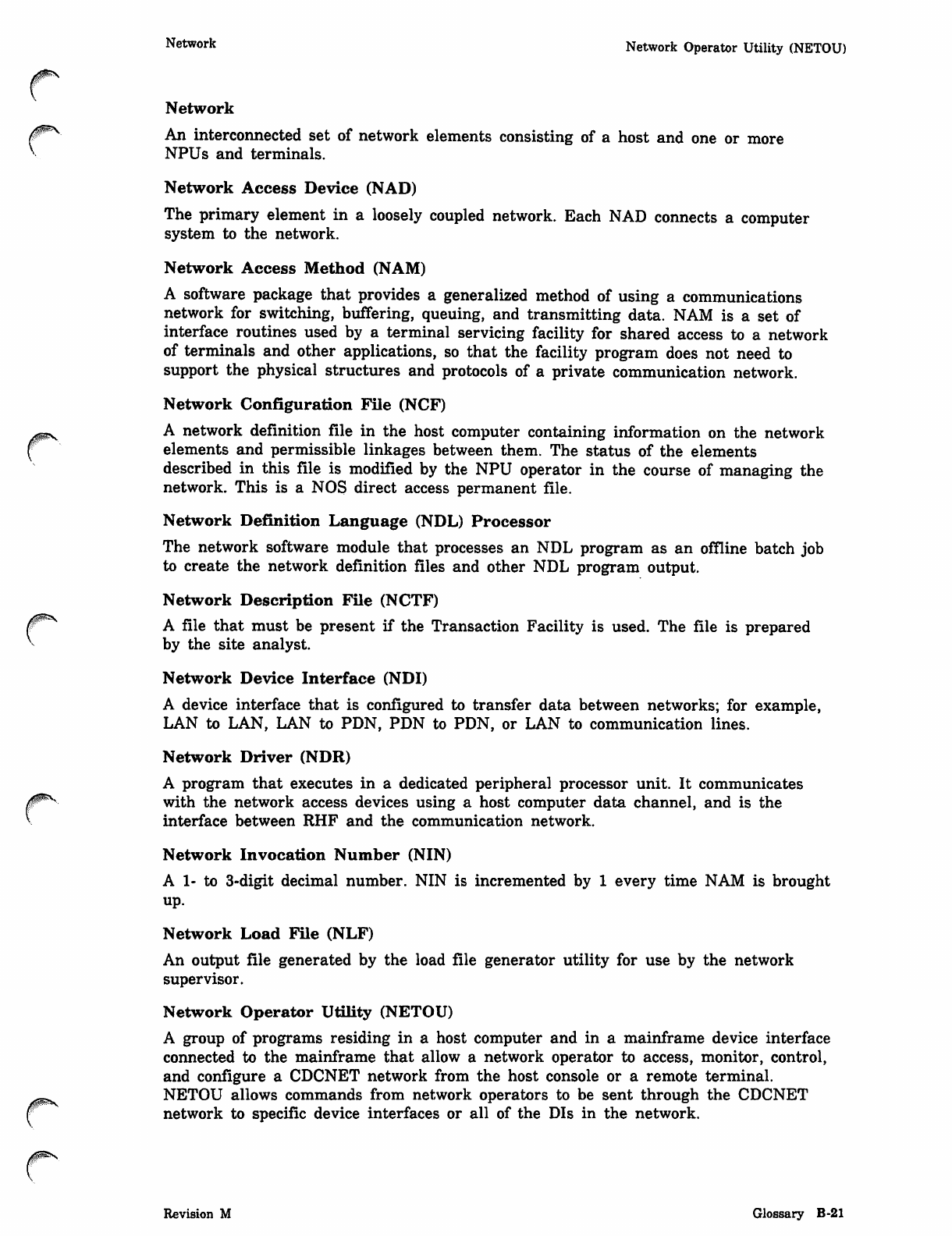
0^S,
Network Network Operator Utility (NETOU)
Network
An interconnected set of network elements consisting of a host and one or more
NPUs and terminals.
Network Access Device (NAD)
The primary element in a loosely coupled network. Each NAD connects a computer
system to the network.
Network Access Method (NAM)
A software package that provides a generalized method of using a communications
network for switching, buffering, queuing, and transmitting data. NAM is a set of
interface routines used by a terminal servicing facility for shared access to a network
of terminals and other applications, so that the facility program does not need to
support the physical structures and protocols of a private communication network.
Network Configuration File (NCF)
A network definition file in the host computer containing information on the network
elements and permissible linkages between them. The status of the elements
described in this file is modified by the NPU operator in the course of managing the
network. This is a NOS direct access permanent file.
Network Definition Language (NDL) Processor
The network software module that processes an NDL program as an offline batch job
to create the network definition files and other NDL program output.
Network Description File (NCTF)
A file that must be present if the Transaction Facility is used. The file is prepared
by the site analyst.
Network Device Interface (NDI)
A device interface that is configured to transfer data between networks; for example,
LAN to LAN, LAN to PDN, PDN to PDN, or LAN to communication lines.
Network Driver (NDR)
A program that executes in a dedicated peripheral processor unit. It communicates
with the network access devices using a host computer data channel, and is the
interface between RHF and the communication network.
Network Invocation Number (NIN)
A 1- to 3-digit decimal number. NIN is incremented by 1 every time NAM is brought
up.
Network Load File (NLF)
An output file generated by the load file generator utility for use by the network
supervisor.
Network Operator Utility (NETOU)
A group of programs residing in a host computer and in a mainframe device interface
connected to the mainframe that allow a network operator to access, monitor, control,
and configure a CDCNET network from the host console or a remote terminal.
NETOU allows commands from network operators to be sent through the CDCNET
network to specific device interfaces or all of the DIs in the network.
Revision M Glossary B-21
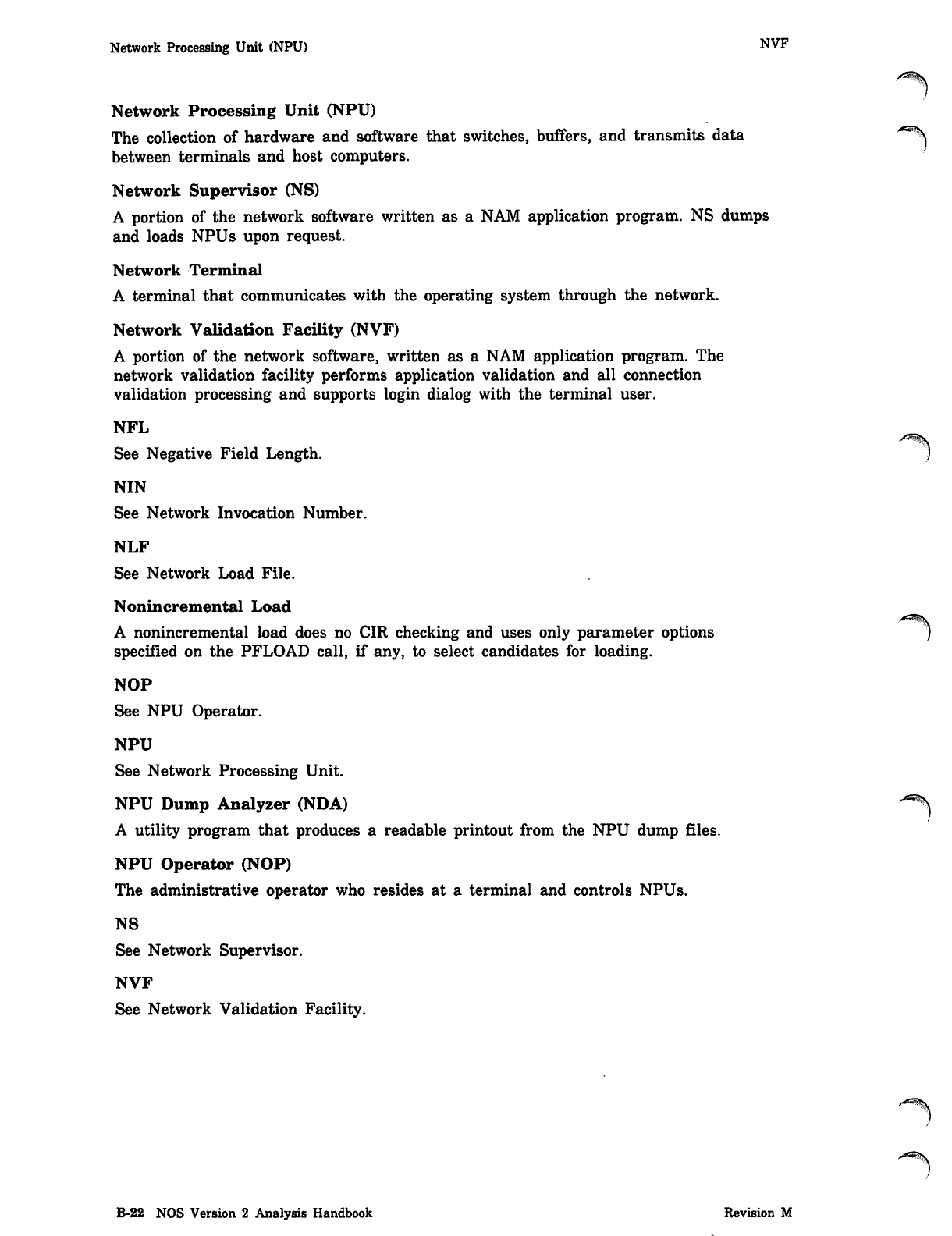
Network Processing Unit (NPU) NVF
Network Processing Unit (NPU)
The collection of hardware and software that switches, buffers, and transmits data /<5\
between terminals and host computers.
Network Supervisor (NS)
A portion of the network software written as a NAM application program. NS dumps
and loads NPUs upon request.
Network Terminal
A terminal that communicates with the operating system through the network.
Network Validation Facility (NVF)
A portion of the network software, written as a NAM application program. The
network validation facility performs application validation and all connection
validation processing and supports login dialog with the terminal user.
NFL
See Negative Field Length. )
NIN
See Network Invocation Number.
NLF
See Network Load File.
Nonincremental Load
A nonincremental load does no CIR checking and uses only parameter options
specified on the PFLOAD call, if any, to select candidates for loading.
NOP
See NPU Operator.
NPU
See Network Processing Unit.
NPU Dump Analyzer (NDA)
A utility program that produces a readable printout from the NPU dump files.
NPU Operator (NOP)
The administrative operator who resides at a terminal and controls NPUs.
NS
See Network Supervisor.
NVF
See Network Validation Facility.
/^^i\
B-22 NOS Version 2 Analysis Handbook Revision M
Object Code PDN
o
Object Code
The machine language version of a program that has been translated (compiled) from
source code written in a higher-level language.
Operating System
The set of system programs that controls the execution of computer programs and
provides scheduling, error detection, input/output control, accounting, compilation,
storage assignment, and other related services.
Origin Type
A job attribute that indicates how a job entered the system. The four origin types are
interactive origin, batch origin, remote batch origin, and system origin.
Output File
rThe system-defined file that contains the output from job processing. It is also known
as the print or punch file.
PACKER Utility
A utility that provides the capability to manage the holes within the indirect access
permanent file chain on a permanent file device.
Paging (Screen)
The process of filling a CRT display with data and holding additional data for
subsequent displays. Changing the page display is an operator-controlled function if
the page-wait option is selected.
Parity
In writing data, an extra bit is either set or cleared in each byte so that every byte
has either an odd number of set bits (odd parity) or an even number of set bits (even
parity). Parity is checked on a read for error detection and possible recovery.
Partial Dump
A partial dump copies permanent files according to any specified options, except those
defining a full or incremental dump.
Password
A name or word the user enters during login to provide extra security for his/her
user name. A unique password ensures that no one else can log into the system with
someone else's user name and access that user's files. A user's password is given to
him/her by that user's employer, instructor, or computer center personnel.
PCP
See Pseudo-control Point.
PDN
See Public Data Network.
Revision M Glossary B-23
Peripheral Interface Package (PIP) Permission Mode
Peripheral Interface Package (PIP)
The interface package between the PPU of the CYBER computer and the network
application.
Peripheral Processor (PP)
The hardware unit within the host computer that performs physical input and output
through the computer's data channels.
Peripheral Processor Unit (PPU)
First level peripheral processor. A PPU is contained in the mainframe in a
multimainframe environment and operates synchronously with the mainframe.
Sometimes referred to as FLPP.
Permanent File
A mass storage file that is cataloged by the system so that its location and
identification are always known to the system. Permanent files cannot be destroyed
accidentally during normal system operation. They are protected by the system from
unauthorized access according to privacy controls specified when they are created.
Permanent File Catalog Entry (PFC)
A 16-word entry that the system maintains and uses to determine the file name,
owner, identification, disk pointers, alternate storage pointers, and other attributes of
a permanent file.
Permanent File Family
The permanent files that reside on the family devices of a specific system.
Permanent File Manager (PFM)
PFM identifies the master device and catalog track information when a user submits
a job.
Permanent File Supervisor (PFS)
The PFS processes parameters in utility commands and loads the correct processing
overlays.
Permanent File Transfer Facility (PTF)
PTF is an application program initiator started by the user using an MFLINK
command. It is responsible for initiating and completing (with the help of its
servicing application, PTFS on another host) a permanent file transfer.
Permanent File Transfer Facility Servicer (PTFS)
PTFS is an application program servicer started by RHF or NAM when requested by
a PTF on another host. The PTFS application assists the PTF application in
completing the file transfer by performing those permanent file functions requested by
the user and then transferring the file between PTF and PTFS.
Permanent File Utility (PFU)
A utility that manages the catalogs, permits, data allocation on a device, and the
data transfer between the device and the overlay.
Permission Mode
A mode of operation that a user is allowed for a particular permanent file, such as
write, modify, append, read, and so forth.
B-24 NOS Version 2 Analysis Handbook Revision M
^^%v
PFATC Utility PICB
PFATC Utility
f A utility that produces a cataloged directory of file information derived from an
archive file previously created by the PFDUMP utility.
PFC
See Permanent File Catalog.
PFCAT Utility
A utility that produces a cataloged directory of file information derived from catalog
tracks on a master device.
PFCOPY Utility
A utility that extracts files from an archive file and copies them to one or more files
at a control point.
PFDUMP Utility
A utility that dumps permanent files to an archive file. Dumps can be reloaded by
the PFLOAD utility and can be accessed by the PFATC and PFCOPY utilities for
cataloging and copying.
PFLOAD Utility
A utility that loads archived files produced by the PFDUMP utility back into the
permanent file system. The load can reestablish the permanent file system exactly as
it was at the time of the dump, or can load only a desired subset of files on the
archive file.
PFM
See Permanent File Manager.
PFREL Utility
A utility that releases disk space for permanent files that have copies on alternate
storage.
PFS
See Permanent File Supervisor.
PFU
See Permanent File Utility.
Physical Identifier (PID)
The unique 3-character identifier of a specific host.
Physical Record Unit (PRU)
The amount of information transmitted by a single physical operation of a specified
device. For mass storage files, a PRU is 64 central memory words (640 characters);
for magnetic tape files, the size of the PRU depends upon the tape format. A PRU
that is not full of user data is called a short PRU; a PRU that has a level
terminator but no user data is called a zero-length PRU.
PICB
See Program Initiation Control Block.
Revision M Glossary B-25
/<^K
PID Program Initiation Control Block (PICB)
PID
See Physical Identifier.
PIP
See Peripheral Interface Package.
PP
See Peripheral Processor.
PPS
The Peripheral Processor Subsystem.
PPU
See Peripheral Processor Unit.
Preserved File
A mass storage file that is recovered on all levels of system deadstart. Preserved files y13^
include permanent files, queued files, and system dayfiles. '
Primary File
A temporary file created with the OLD, NEW, LIB, (interactive jobs only), or
PRIMARY command. The primary file is assumed to be the file on which most
system operations are performed unless another file is specified. There can be only
one primary file associated with your job.
Primary VSN
The volume serial number (VSN) of a single reel destage dump tape or the VSN of
the first reel of a multireel set of destage dump tapes. The VSN must be two
alphanumeric characters followed by a four-digit decimal number; the number must
be in the range 0000 through 4095.
Privileged Analyst
A user with AW=CPAM validation (refer to the NOS Version 2 Administration
Handbook for information on MODVAL validation). Such a user can read system
status information (such as the system dayfile, account file, and error log) using a
nonsystem-origin job if PRIVILEGED ANALYST MODE is enabled (via IPRDECK or ^
DSD command). Note that PRIVILEGED ANALYST MODE cannot be enabled on a
secured system.
PROBE Utility
A utility that traps and measures particular interval events in the system. PROBE
generates a report from the data collected by the system.
Procedure
A user-defined set of instructions that can be referenced by name. The instructions
consist of procedure directives and system commands.
Program Initiation Control Block (PICB)
A sequence of commands that initiates NPU load and dump operations for a specific
NPU variant. Several PICBs may exist on the network load file. Each PICB is a
separate record with a unique NPU variant name as its record name.
B-26 NOS Version 2 Analysis Handbook Revision M
0ms
Programmable Format Control PTFS
Programmable Format Control
Spacing and format control for 580 line printers provided by the use of software and
a microprocessor instead of a carriage control format tape.
Project Number
An alphanumeric identifier that may be required at a user's installation for
accounting and billing to a specific project. If it is required, the project number is
entered during the login procedure. It is given to the user by personnel at his/her
installation.
Protocol
A set of conventions or rules that must be used to achieve complete communication
between entities in a network. A protocol can be a set of predefined coding sequences
such as the control byte envelopes added to or removed from data exchanged with a
terminal; a set of data addressing and division methods, such as the block mechanism
used between an application program and NAM; or a set of procedures used to
control communication, such as the supervisory message sequences used between an
application program and NAM.
PRU
See Physical Record Unit.
Pseudo A Register
A software register used by DSD to function channels and to manipulate peripheral
hardware devices from the operator's console.
Pseudo-control Point (PCP)
The portion of central memory that is assigned to a job that has been pseudo-rolled.
Pseudo-control points are the same as control points except that a job at a
pseudo-control point cannot have any activity (such as PP assignment or CPU
assignment).
Pseudo-control Point Number
The number of the pseudo-control point to which a job is assigned while the job
resides in central memory. The actual number of pseudo-control points is an
installation parameter.
Pseudo-rollout
The removal of jobs from a control point to a pseudo-control point so that the control
point and central memory can be assigned to another job. A job is rolled out to a
pseudo-control point when its control point is needed by a higher priority job.
Pseudo-rollin
The return of jobs from a pseudo-control point to a control point.
PTF
See Permanent File Transfer Facility.
PTFS
See Permanent File Transfer Facility Servicer.
Revision M Glossary B-27
Public Auxiliary Device "
Public Auxiliary Device
An auxiliary device that is available for access by all validated users knowing the ^
correct pack name. Additional validation is required to create or replace files on an
auxiliary device.
Public Data Network (PDN)
A commercial packet-switching network that supports the interface described in the
CCITT protocol X.25.
Q
QALTER Utility
A utility that displays, lists, and/or alters routing and other information about active
queued files. It selects files for processing according to specified criteria. QALTER can
also purge selected files from the system.
QDUMP Utility
A utility that dumps selected queued files from a single device, a family of devices,
or all devices on the system. These queued files can be dumped either to a tape or
disk. QDUMP also provides a listing of all files dumped with information about each
file processed.
QFSP
See Queue File Supervisor Program.
QFT
See Queued File Table.
QFTLIST Utility
A utility that displays and/or lists routing and other information about active queued
files. Its operation is similar to that of QALTER, except file alteration or purging is
not allowed.
QLIST Utility
A utility that lists inactive queued files, which may include all inactive queued files
in the system or a selected subset based on options specified when the utility is
called.
QLOAD Utility
A utility that processes the dump files generated by QDUMP or other utilities using
the same format. QLOAD can selectively load the queued files from these dump files.
QLOAD can also list the contents of a dump file without loading any files.
QMOVE Utility
A utility that moves queued files from one disk device to another. It also produces a
listing of all files moved with information about each file processed.
QREC Utility
A utility that deactivates or activates selected queued files and purges selected
inactive queued files.
QTF
See Queue File Transfer Facility.
B-28 NOS Version 2 Analysis Handbook Revision M
/<S^v
0ms,
QTFS Recall
QTFS
See Queue File Transfer Facility Servicer.
Queue File Supervisor Program (QFSP)
A program that provides control for the queue file utilities.
Queue File Transfer Facility (QTF)
QTF is an application program initiator that periodically scans the I/O queues
searching for files to transfer. When it finds a file to transfer, it initiates and
completes the queue file transfer with the help of its servicing application, QTFS, on
another host.
Queue File Transfer Facility Servicer (QTFS)
QTFS is an application program servicer started by RHF or NAM when requested by
a QTF on another host. The QTFS application assists the QTF application in
completing the transfer by receiving the queue file and placing it in the I/O queue.
Queue Priority
An attribute associated with input and output files. If all other factors are equal,
queue priority is used to select the best file for processing.
Queued File
An input, print, plot, or punch file that has an entry in the QFT, is not assigned to
an EJT entry, and is waiting to be selected for processing.
Queued File Table (QFT)
A central memory resident table that contains a 4-word entry for all active input and
output queue files.
R
Random Access
An access method by which any record in a file can be accessed at any time. Random
access applies only to mass storage files with an organization other than sequential.
Refer to Sequential Access.
RCFGEN
See RHF Configuration File Generation.
RCL
See Resident Central Library.
RDF
See Release Data File.
Recall
The state of a program when it has released control of the central processor until a
fixed time has elapsed (periodic recall) or until a requested function is completed
(auto recall). Recall is a system action request as well as an optional parameter of
some file action requests.
Revision M Glossary B-29
Record Rollout
Record
A unit of information. In CYBER Record Manager and its language processors, a
record is a unit of information produced by a single read or write request.
Eight different record types exist within CRM. The user defines the structure and
characteristics of records within a file by declaring a record format.
Regulation Level
A number that indicates to NAM the existence of a logical link and indicates what
types of information exchange are possible on that logical link.
Release Data File (RDF)
A file created by PFDUMP that identifies those 7990-resident files that are pointed to
by PFC entries at the time of the dump.
Remote Batch Job
A job submitted from a remote batch terminal.
Remote Host Facility (RHF)
A central processor program that executes at a system control point. It performs data
buffering and switching, and is the intermediary between application programs and
the network.
Remote NAD
Any 380 NAD accessible to a local NAD using a loosely coupled network trunk.
Remote NPU
A network processing unit linked to a host computer through other network
processing units.
Removable Device
A disk storage device that can be physically detached from the disk drive.
Resident Central Library (RCL)
An area in central memory resident that central library routines specified by the
*CM directive reside.
Resident Peripheral Library (RPL)
An area in central memory resident that peripheral library routines specified by the
*CM directive reside.
RHF
See Remote Host Facility.
RHF Configuration File Generation (RCFGEN)
A utility that reads configuration definition statements to create a permanent file
that RHF uses for the network description and access.
Rollout
The removal of jobs from central memory to mass storage before execution is
complete, so the control point and central memory can be assigned to another job. A
job is rolled out when it is waiting for an external event, when its control point
and/or central memory is needed by a higher priority job, or when it exceeds its
central memory time slice.
B-30 NOS Version 2 Analysis Handbook Revision M
<*^*\
0ms
0ms
*°nout File Secondary Mask
Rollout File
A file containing a job (and system information) that has been temporarily removed
from the main processing area of the system.
RPL
See Resident Peripheral Library.
SC
See Service Class.
S/C Register
See Status/Control Register.
Scheduling Priority
An attribute associated with an executing job available for job scheduling. Scheduling
priority is used to select the best executing service class job for processing.
SCOPE 2 Station Facility (SSF)
A NOS subsystem that allows a NOS user to submit jobs (including batch jobs that
require interactive I/O) to a linked SCOPE 2 system. The submitted job uses standard
SCOPE 2 commands to access NOS files stored on the originating NOS system.
SCP
See Subcontrol Point.
Screen Management Facility (SMF)
A subsystem that alters the performance characteristics of the Full Screen Editor
(FSE). The absence or presence of SMF is not detectable by the FSE user.
Performance can be optimized by disabling SMF for small mainframes and interactive
work loads, and by enabling SMF for large configurations and heavy work loads.
SCRSIM
See Status/Control Register Simulator.
SDF
See System Deadstart File.
SECDED
See Single Error Correction Double Error Detection.
Secondary Mask
An 8-bit quantity used to identify groups of users who can place direct access files on
a particular device.
Revision M Glossary B-31
Secondary VSN SM MaP
Secondary VSN
The VSN of a single reel destage dump tape or the VSN of the first reel of a '^
multireel set of destage dump tapes having a sequence number (the last four
characters of the VSN) in the range 5000 through 9095. The existence of a secondary
VSN assumes the existence of a primary VSN having the same two-character prefix
and a sequence number of 5000 less. The primary and secondary VSN tapes or
multireel sets of tapes are assumed to contain identical data although the individual
reels of multireel sets cannot be assumed identical.
Secured System
A system in which a mandatory security mechanism has been enabled during
deadstart. A secured system protects information by enforcing restrictions based on
access levels and access categories, and restricts many sensitive system functions to
security administrators.
Security Administrator
A secured system prevents users and operators from performing certain functions that
could result in the unauthorized disclosure or modification of information. These
functions can only be performed by someone who is designated a security
administrator. A security administrator is always authorized to access the highest
level of information stored on the system. This person performs functions in the areas
of installation, user validation, system operation, and system maintenance.
Security Unlock Status
This status of the system console applies only to a secured system and must be set
by a security administrator. The console must be in security unlock status in order
for the security administrator to perform certain functions that are restricted on a
secured system.
Sequential Access
A method in which only the record located at the current file position can be
accessed. Refer to Random Access.
Sequential (SQ) File
A file in which records are accessed in the order in which they occur. Any file can
be accessed sequentially.
Service Class (SC)
An attribute associated with a queued file or executing job. The service class
determines how the system services the job.
SFS
See Special File Supervisor.
Single Error Correction Double Error Detection (SECDED)
A hardware technique that detects and corrects single bit errors in memory. Double
bit errors are detected by not corrected.
SM
See Storage Module.
S M M a p ^ %
See Storage Module Map.
B-32 NOS Version 2 Analysis Handbook Revision M
SMF SSMOVE Utility
SMF
(^^ See Screen Management Facility.
Source Code
Code input to the computer for later translation into executable machine language
instructions (object code).
Special File Supervisor (SFS)
A program that provides routines, table management, data manipulation, and I/O
processing for special system jobs.
SQ File
See Sequential File.
SRU
See System Resource Unit.
SSALTER Utility
A utility that displays the current 7990 hardware configuration and allows an analyst
to change the status of certain elements in the 7990 configuration.
SSBLD Utility
A utility that processes statements consisting of 7990 component-oriented mnemonics
that define the logical mapping within the 7990 configuration, SSBLD generates a
direct-access permanent file which SSEXEC uses as its unit device table.
^ SSDEBUG Utility
A utility that allows an analyst to update appropriate entries in the SM maps and/or
7990 catalogs and thereby resolve inconsistencies reported by the SSVAL utility.
SSDEBUG can also be used to copy data from selected 7990 files or cartridges to
disk.
SSDEF Utility
A utility that creates the system files (SM maps and 7990 catalogs) that are
necessary for MSE processing.
SSEXEC Program
The main processing program that controls MSE activities, such as destaging files
from disk to the 7990, purging unneeded 7990 files, labeling or relabeling cartridges,
updating SM maps, and updating 7990 catalogs.
SSF
See SCOPE 2 Station Facility.
SSLABEL Utility
A utility that manages cartridge assignment and cubicle allocation in a storage
module.
SSMOVE Utility
A utility that manages disk and 7990 residence. SSMOVE determines which files to
leave on disk, which files to release from disk and move to 7990, and which files
should reside both on disk and on 7990.
Revision M Glossary B-33
SSSLV Program Storage Module (SM) Map
SSSLV Program
A program that runs on each slave mainframe and communicates with the SSEXEC *^\
program to retrieve files from the 7990 in response to ATTACH requests by jobs
running on the slave mainframes.
SSUSE Utility
A utility that reads data in the 7990 catalogs and SM maps and produces reports on
the availability of space on 7990 cartridges and the allocation of cubicle space within
an SM.
SSVAL Utility
A utility that either performs release processing or reports on problems with the
current MSE system files.
Staging
The process of restoring file data to disk residence from a copy on alternate storage.
Staging is initiated when a user executes an APPEND, ATTACH, GET, or OLD
command for a file that is not currently disk resident.
Status
Information relating to the current state of a device, line, and so forth. Service
messages are the principal carriers of status information. Statistics are a special
subclass of status.
Status/Control Register Simulator (SCRSIM)
A program that enables the user to set status/control register bits in order to aid in
the testing of error logging and error recovery procedures. '^^j
Status/Control (S/C) Register
A hardware register used in error detection, logging, and recovery procedures. This
register is present on all CYBER 170 Computer Systems. For models 865 and 875,
the S/C register is replaced by a maintenance register. Refer to Maintenance
Register.
Step Mode
A protected or debugging mode for the operating system monitor. The keyboard 'eS!s\
spacebar must be pressed to process each PP request. '
Stimulator
A collection of central memory and peripheral processor programs that enters a
hypothetical work load into the system to analyze the effects of such a load on
response time and system reliability.
Storage Module (SM)
An MSE hardware unit that houses up to 312 usable data cartridges, a cartridge
accessor unit that picks cartridges from and puts cartridges in their cubicles, and one
or two data recording drives.
Storage Module (SM) Map
A direct access permanent file that contains information indicating the cartridges that
reside in the SM.
B-34 NOS Version 2 Analysis Handbook Revision M
0ms
Subcontrol Point (SCP) Tape Alternate Storage
Subcontrol Point (SCP)
A division of a central memory control point. You can set up a control point to
contain two or more programs; one of the programs is the executive, and monitors
the other programs executing at the subcontrol points.
Subfamily
Each permanent file family consists of eight subfamilies, subfamily 0 through
subfamily 7. The lower 3 bits of the user index identify the subfamily to which a
user belongs.
Suspended Job
An interactive job placed in a inactive state. Processing is stopped immediately and
recovery information is copied to the rollout file. Processing is resumed as if no
interruption took place, if the job's EJT entry is recovered.
System Access Categories
On a secured system, a set of access categories are set during level 0 deadstart. This
set may consist of some, all, or none of the 32 possible access categories. While the
system is running in security mode, you may only use access categories that are
within the set of system access categories.
System Access Levels
On a secured system, a range of access levels is set during level 0 deadstart. This
range may contain some or all of the eight possible access levels. While the system is
rurining, users may only use access levels that are within the range of system access
levels.
System Deadstart File (SDF)
A file that is a copy of the deadstart tape that resides on a disk storage deadstart
device. When the system is deadstarted from disk, this file is read to generate copies
of the running system.
System Library (SYSTEM)
The collection of tables and object language programs that reside in central memory
or on mass storage and are necessary for running the operating system and its
product set.
System Origin Job
A job entered at the system console.
System Resource Unit (SRU)
A unit of measurement of system usage. The number of SRUs includes the central
processor time, memory usage, and input/ output resources used for a given job.
TAF
See Transaction Facility.
Tape Alternate Storage
Magnetic tape used as an alternate storage medium for permanent files. See
Alternate Storage.
Revision M Glossary B-35
TCU UEM
TCU
See Trunk Control Unit. '^)
TDI
See Terminal Device Interface.
Temporary File
A file associated with a job that is not a permanent file. Temporary files no longer
exist when the user logs off the system or releases the files.
Terminal Device Interface (TDI)
A device interface that is configured to support terminal-to-network communications.
Timed/Event Rollout
A condition in which an executing job has been temporarily removed from central
memory but will be rolled back into central memory when a specified event (such as
a file is no longer busy) or a specified time period has elapsed. A-ms
TRACER Utility
A utility that monitors the system's activity and gathers data periodically for
statistical analysis of the system.
Track Link
An address of the next track that is a logical continuation of a file.
Track Reservation Table (TRT)
A table that describes the physical layout of data on a device and is the key to
allocating information on the device.
Transaction Facility (TAF)
An application program that provides the transaction terminal with access to a data
base. A terminal using TAF can enter, retrieve, and modify information in the data
base.
TRT
See Track Reservation Table.
Trunk
The communication line connecting two network processing units.
Trunk Control Unit (TCU)
The hardware part of a network access device (NAD) that interfaces with a network
trunk.
u
UDT
See Unit Device Table.
UEM
See Unified Extended Memory. )
B-36 NOS Version 2 Analysis Handbook Revision M
/sj<eS*\.
Unified Extended Memory (UEM) User Name
Unified Extended Memory (UEM)
A type of extended memory that is available as an option for CYBER 180-class
machines and models 865 and 875. UEM differs from other types of extended memory
in that it is a portion of central memory and not a separate memory unit. See
Extended Memory.
Unit Device Table (UDT)
A table that defines the logical mapping of the components within a 7990
configuration.
Unit Number
The setting of a hardware device. The unit number is used when more than one
hardware unit can be connected to a controller.
Unsecured System
A system in which the multilevel security mechanism has not been enabled during
deadstart. The restrictions based on access levels and access categories are not
enforced on an unsecured system.
Upline
The direction of input flow from terminal to host.
User Break 1 Sequence
The character or sequence of characters that causes an executing program to be
interrupted (also called the interruption sequence).
User Break 2 Sequence
The character or sequence of characters that causes an executing program to be
terminated (also called the termination sequence).
User Index
A unique 17-bit identifier that is associated with each user name. The user index is
used by the permanent file manager to identify the device and catalog track for the
user's permanent files.
User Job Name (UJN)
A 1- to 7-character alphanumeric name you specify to replace the system defined JSN
for a queued file or executing job.
User Name
A name given to the user by his/her employer, instructor, or computer center
personnel. A user name has certain resources and privileges assigned to it. When
logging in to the system, a user specifies his/her user name as identification, so that
it knows that this person is an authorized user and what resources this user is
entitled to use. A user name also represents a specific catalog in the permanent file
system. All files a user makes permanent are associated with that user's name and
this catalog.
Revision M Glossary B-37
Validation File ?990 Catal°g
V
Validation File
A file that contains validation information for all users (user names, passwords,
resources allowed, and so on).
Volume Serial Number (VSN)
A from 1- to 6-character identifier that identifies the volume of magnetic tape to the
system.
VSN
See Volume Serial Number.
w
Word
A group of bits (or 6-bit characters) between boundaries imposed by the computer "*%
system. A word is 60 bits in length. The bits are numbered 59 through 0 starting
from the left. A word is also composed of five 12-bit bytes, numbered 0 through 4
from the left.
Write Mode
A mode that allows a user to write, modify, append, read, execute, or purge the file
(modify permission applies only to direct access files).
Zero-Length PRU
A PRU that contains system information but no user data. Under NOS, a zero-length
PRU defines EOF.
7990
A hardware product that is a large capacity mass storage device. The 7990 is a
cost-effective extension to the disk file storage system and an alternative to
conventional magnetic tape storage.
7990 Catalog
A disk-resident direct access permanent file that contains information describing
which AUs of each cartridge assigned to a particular subfamily are allocated to 7990
files and which AUs are available for allocation.
B-38 NOS Version 2 Analysis Handbook Revision M
/ f ^ v Scope 2 Station Facility
The SCOPE 2 Station Facility (SSF) is a NOS software subsystem that allows a NOS
user to submit jobs and transfer files to a linked SCOPE 2 system residing in a 7000
Computer Systems mainframe. With SSF, a NOS user can route jobs to a linked
SCOPE 2 system for processing. While processing the job, the SCOPE 2 system can
access permanent files and tape files at the NOS host.
SSF provides these services:
Provides NOS users with local batch capabilities at a linked SCOPE 2 system.
Optionally serves as the system operator station for SCOPE 2.
Provides the NOS user with remote batch capabilities, through RBF, at a linked
SCOPE 2 system.
Allows simultaneous transfer of multiple files.
Optionally furnishes the deadstart file for SCOPE 2.
Provides a means of obtaining absolute SCOPE 2 dumps.
Allows a job executing on a SCOPE 2 system to use SCOPE 2 commands (GETPF,
SAVEPF, and PURGE) to access permanent files at a linked NOS system.
Allows a job executing on a SCOPE 2 system to access magnetic tape files at a
linked NOS system.
0jim\
Equipment Configuration
To establish a NOS-SCOPE 2 link using the SSF Subsystem, the NOS and SCOPE 2
mainframes must be attached to a loosely coupled network (LCN) by a 6683 and 7683
Satellite Coupler, respectively. An equipment status table (EST) device type entry of
CC describes the coupler link. The EST table appears on the E,A display.
Revision M Scope 2 Station Facility C-l
SSF File Transfers
SSF File Transfers
SSF file transfers between NOS and SCOPE 2 are of two types:
• Staged file transfers.
• Spooled file transfers.
Staged file transfers process one file at a time and handle all tape file and permanent
file transfers. Spooled file transfers handle multiple I/O file transfers. Normally,
operator intervention is not required for either type of transfer.
SSF initiates a special type of job, called a spunoff task (SPOT) job, to perform file
transfers. Staged file SPOT jobs differ from spooled file SPOT jobs as described in
this appendix. The primary functions of any SPOT job are performing user validation
and queuing tasks required to send a file across the link. All SPOT jobs are executed
on the NOS system.
Installation parameters or operator commands can be used to limit the number of file 'sS%.
transfer activities that can be active concurrently. Independent limits can be set on )
the following activities:
• Purging NOS files.
• Reading tape files from NOS to SCOPE 2.
• Writing tape files from SCOPE 2 to NOS.
• Reading permanent files from NOS to SCOPE 2.
• Writing permanent files from SCOPE 2 to NOS.
• Reading input files from NOS terminals to SCOPE 2.
• Writing output files from SCOPE 2 to NOS terminals.
The operator commands used to set limits are described in section 8, K-Display
Utilities.
C-2 NOS Version 2 Analysis Handbook Revision M
/jffi^Sy
Staged File Transfers
Staged File Transfers
Staged file transfers are essentially the same for both tape and permanent file
transfers. In response to an SSF query, SCOPE 2 indicates to SSF that an executing
SCOPE 2 job requires access to a NOS file. The SCOPE 2 request can specify either a
NOS to SCOPE 2 file transfer, also called a prestaging transfer; or a SCOPE 2 to NOS
(poststaging) transfer. In either case, SSF normally responds by creating a SPOT job to
perform the file transfer. The SPOT job name is of the form xyyy, where x is the last
character of the PID of the SCOPE 2 mainframe, and yyy is the JCB ordinal of the
SCOPE 2 job. SSF places the newly created SPOT job into the NOS input queue, and
the job executes on NOS in the same manner as any other job.
During execution, the job checks that the user has the appropriate file access
permission. If so, the SPOT job initiates the file transfer.
For staged file transfers, each SPOT job terminates upon completion, and the job's
dayfile (containing all processing and error messages) is sent to SCOPE 2 to be
included in the dayfile of the job that requested the file transfer. SSF initiates a new
SPOT job for each staged file transfer request it receives.
SSF periodically queries SCOPE 2 about file staging activities that should be dropped.
For example, the SCOPE 2 system operator may have dropped a job for which
staging was active. If any file staging activities are to be dropped, SSF requests
information to identify the staging activity and then drops the associated SPOT job.
No operator intervention is required.
Spooled File Transfers
Spooled file transfers use a single SPOT job to perform all input/output file transfers
between SSF and SCOPE 2. As soon as communications are established between SSF
and SCOPE 2, SSF creates a SPOT job to handle input/output file transfers. The job is
called xSTA, where x is the PID of the SCOPE 2 mainframe. This SPOT job can be
swapped out during periods of low activity, but the job is not terminated until the
SSF-SCOPE 2 link is dropped.
An input file transfer begins when the spooling SPOT job selects a file from the NOS
input queue that is destined for the SCOPE 2 system. The SPOT job queries SCOPE
2 for a system file table (SFT) entry for the input file to be transferred. When an
entry is assigned, the spooling SPOT job transfers the input file to SCOPE 2. Upon
completion of the transfer, the SPOT job requests that the input file be removed from
the NOS input queue.
For each output file transferred from SCOPE 2, the spooling SPOT job transfers the
output file from the SCOPE 2 output queue to a local NOS file. When the transfer is
complete, the SPOT job routes the local file to the NOS output queue (with the
appropriate disposition code, forms code, or terminal ID). The spooling SPOT job then
requests the removal of the output file from the SCOPE 2 output queue.
Revision M Scope 2 Station Facility C-3
Error Logout
Error Logout
A loss of communications between SSF and SCOPE 2 results in an error logout
condition. Error logout occurs as a result of a STOP command entered by the system
operator, or a software or hardware error. When SSF detects an interruption in
communications, it logs out of the SCOPE 2 system after:
• All partially transmitted files are rewound on the sending end of the link and are
deleted at the receiving end.
• All SPOT jobs are dropped.
No files are lost as a result of the communications break. After logging out of the
SCOPE 2 system, SSF periodically queries SCOPE 2 to determine if the link has been
restored.
C-4 NOS Version 2 Analysis Handbook Revision M
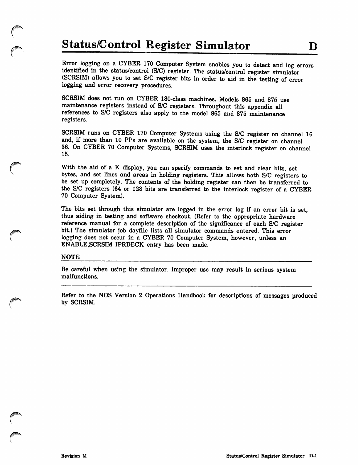
Status/Control Register Simulator
Error logging on a CYBER 170 Computer System enables you to detect and log errors
identified in the status/control (S/C) register. The status/control register simulator
(SCRSIM) allows you to set S/C register bits in order to aid in the testing of error
logging and error recovery procedures.
SCRSIM does not run on CYBER 180-class machines. Models 865 and 875 use
maintenance registers instead of S/C registers. Throughout this appendix all
references to S/C registers also apply to the model 865 and 875 maintenance
registers.
SCRSIM runs on CYBER 170 Computer Systems using the S/C register on channel 16
and, if more than 10 PPs are available on the system, the S/C register on channel
36. On CYBER 70 Computer Systems, SCRSIM uses the interlock register on channel
15.
With the aid of a K display, you can specify commands to set and clear bits, set
bytes, and set lines and areas in holding registers. This allows both S/C registers to
be set up completely. The contents of the holding register can then be transferred to
the S/C registers (64 or 128 bits are transferred to the interlock register of a CYBER
70 Computer System).
The bits set through this simulator are logged in the error log if an error bit is set,
thus aiding in testing and software checkout. (Refer to the appropriate hardware
reference manual for a complete description of the significance of each S/C register
bit.) The simulator job dayfile lists all simulator commands entered. This error
logging does not occur in a CYBER 70 Computer System, however, unless an
ENABLE,SCRSIM IPRDECK entry has been made.
NOTE
Be careful when using the simulator. Improper use may result in serious system
malfunctions.
Refer to the NOS Version 2 Operations Handbook for descriptions of messages produced
by SCRSIM.
Revision M Status/Control Register Simulator D-l
Using the Simulator
Using the Simulator
Error logging is always enabled on a CYBER 170 Computer System except models 815,
825, 835, 845, and 855. Error logging is enabled on a CYBER 70 Computer System
only if the ENABLE,SCRSIM IPRDECK entry is present.
Console Operation
The simulator is called from the console by entering:
x.SCRSIM.
The simulator K display (refer to figure D-l) appears on the left screen after entering:
KJsn.
Entry Description
j s n T h e j o b s e q u e n c e n a m e o f S C R S I M n o t e d o n t h e B , 0 d i s p l a y . ^ \
This K display shows the contents of the temporary holding registers, as well as a
central memory buffer. The buffer contains:
© A history of all error status bits since the last level 0 deadstart. If an error status
bit has been set in the S/C register, it remains set in the buffer, even though it
may have been cleared in the actual S/C register. This history may be useful in
diagnosing system malfunctions.
• All other bits in the buffer reflect actual values in the S/C register at the time the
last error bit was set. Each time an error bit is set, the entire buffer is updated.
Unless the simulator is running on a CYBER 170 Computer System with more than 10
PPs, the message
CHANNEL 36 NOT AVAILABLE
also appears. This indicates that no channel 36 S/C register is present on the machine,
and thus, no simulation need be done for it.
By entering
KK.
the simulator commands K display (refer to figure D-2) appears on the right screen.
This display gives a brief description of the commands available.
Commands can be entered on the K display by entering:
K.command.
Entry Description
command One of the commands shown in figure D-2.
D-2 NOS Version 2 Analysis Handbook Revision M
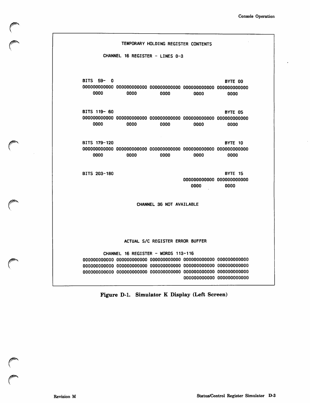
Console Operation
yf^mS!^ TEMPORARY HOLDING REGISTER CONTENTS
CHANNEL 16 REGISTER - LINES 0-3
BITS 59- 0 BYTE 00
OOOOOOOOOOOO OOOOOOOOOOOO OOOOOOOOOOOO OOOOOOOOOOOO oooooooooooo
OOOO OOOO oooo oooo oooo
BITS 119- 60 BYTE 05
OOOOOOOOOOOO oooooooooooo oooooooooooo oooooooooooo oooooooooooo
oooo oooo oooo oooo oooo
BITS 179-120 BYTE 10
oooooooooooo oooooooooooo oooooooooooo oooooooooooo oooooooooooo
oooo oooo oooo oooo oooo
BITS 203-180 BYTE 15
oooooooooooo oooooooooooo
oooo oooo
CHANNEL 36 NOT AVAILABLE
ACTUAL S/C REGISTER ERROR BUFFER
CHANNEL 16 REGISTER - WORDS 113-116
oooooooooooo oooooooooooo oooooooooooo oooooooooooo oooooooooooo
oooooooooooo oooooooooooo oooooooooooo oooooooooooo oooooooooooo
oooooooooooo oooooooooooo oooooooooooo oooooooooooo oooooooooooo
oooooooooooo oooooooooooo
Figure D-l. Simulator K Display (Left Screen)
Revision M Status/Control Register Simulator D-3
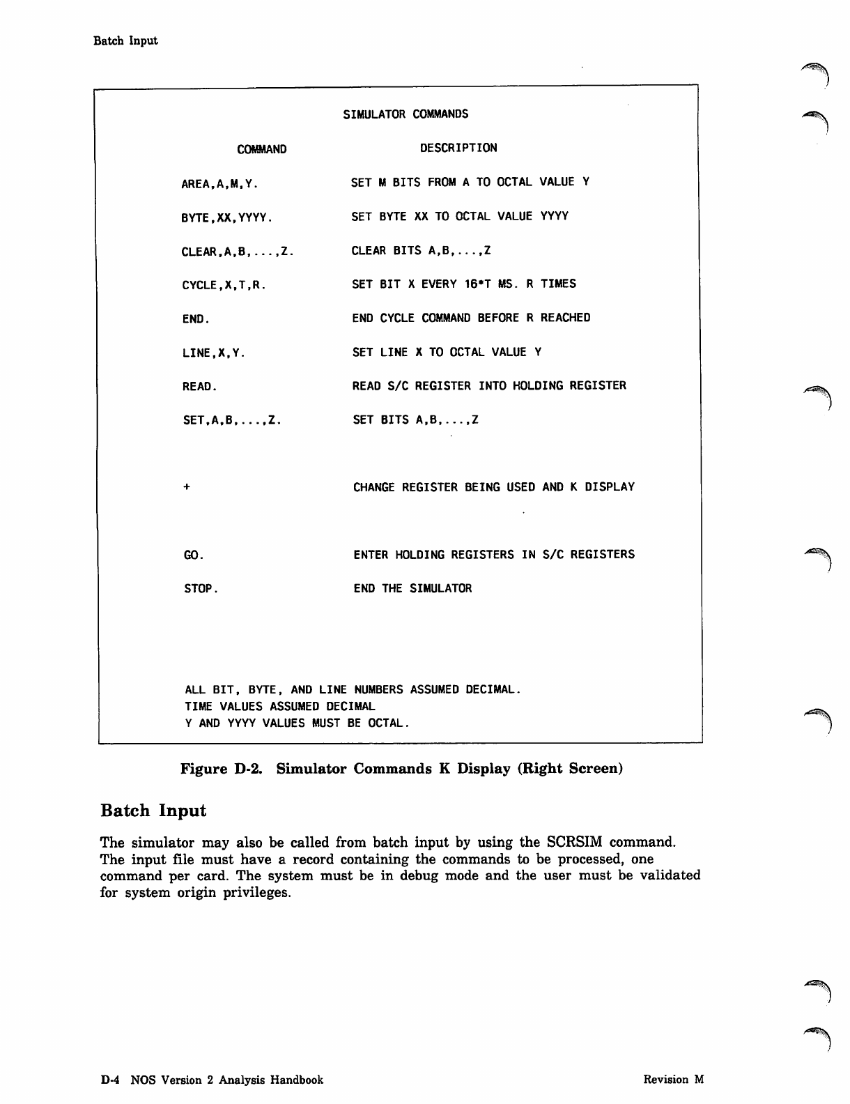
Batch Input
COMMAND
AREA.A.M.Y.
BYTE,XX,YYYY.
CLEAR,A,B Z.
CYCLE,X,T,R.
END.
LINE.X.Y.
READ.
SET.A.B Z.
GO.
STOP.
SIMULATOR COMMANDS
DESCRIPTION
SET M BITS FROM A TO OCTAL VALUE Y
SET BYTE XX TO OCTAL VALUE YYYY
CLEAR BITS A,B,...,Z
SET BIT X EVERY 16*T MS. R TIMES
END CYCLE COMMAND BEFORE R REACHED
SET LINE X TO OCTAL VALUE Y
READ S/C REGISTER INTO HOLDING REGISTER
SET BITS A,B Z
CHANGE REGISTER BEING USED AND K DISPLAY
ENTER HOLDING REGISTERS IN S/C REGISTERS
END THE SIMULATOR
ALL BIT, BYTE, AND LINE NUMBERS ASSUMED DECIMAL.
TIME VALUES ASSUMED DECIMAL
Y AND YYYY VALUES MUST BE OCTAL.
Figure D-2. Simulator Commands K Display (Right Screen)
Batch Input
The simulator may also be called from batch input by using the SCRSIM command.
The input file must have a record containing the commands to be processed, one
command per card. The system must be in debug mode and the user must be validated
for system origin privileges.
^S^v
D-4 NOS Version 2 Analysis Handbook Revision M
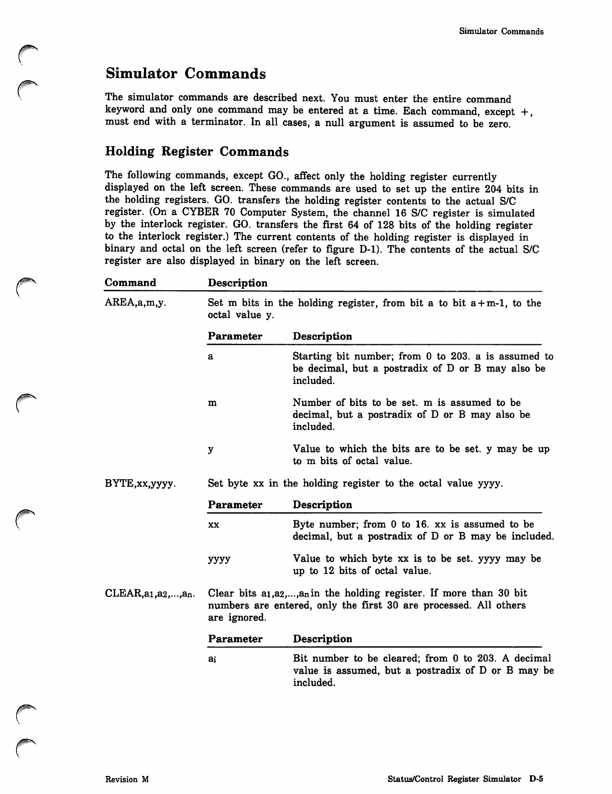
0ms
Simulator Commands
Simulator Commands
The simulator commands are described next. You must enter the entire command
keyword and only one command may be entered at a time. Each command, except +,
must end with a terminator. In all cases, a null argument is assumed to be zero.
Holding Register Commands
The following commands, except GO., affect only the holding register currently
displayed on the left screen. These commands are used to set up the entire 204 bits in
the holding registers. GO. transfers the holding register contents to the actual S/C
register. (On a CYBER 70 Computer System, the channel 16 S/C register is simulated
by the interlock register. GO. transfers the first 64 of 128 bits of the holding register
to the interlock register.) The current contents of the holding register is displayed in
binary and octal on the left screen (refer to figure D-l). The contents of the actual S/C
register are also displayed in binary on the left screen.
Command Description
AREA,a,m,y. Set m bits in the holding register, from bit a to bit a + m-1, to the
octal value y.
Parameter Description
Starting bit number; from 0 to 203. a is assumed to
be decimal, but a postradix of D or B may also be
included.
m Number of bits to be set. m is assumed to be
decimal, but a postradix of D or B may also be
included.
Value to which the bits are to be set. y may be up
to m bits of octal value.
BYTE,xx,yyyy. Set byte xx in the holding register to the octal value yyyy.
Parameter Description
xx
yyyy
Byte number; from 0 to 16. xx is assumed to be
decimal, but a postradix of D or B may be included.
Value to which byte xx is to be set. yyyy may be
up to 12 bits of octal value.
CLEAR,ai,a2,...,an. Clear bits ai,a2,...,anin the holding register. If more than 30 bit
numbers are entered, only the first 30 are processed. All others
are ignored.
Parameter
ai
Description
Bit number to be cleared; from 0 to 203. A decimal
value is assumed, but a postradix of D or B may be
included.
Revision M Status/Control Register Simulator D-5
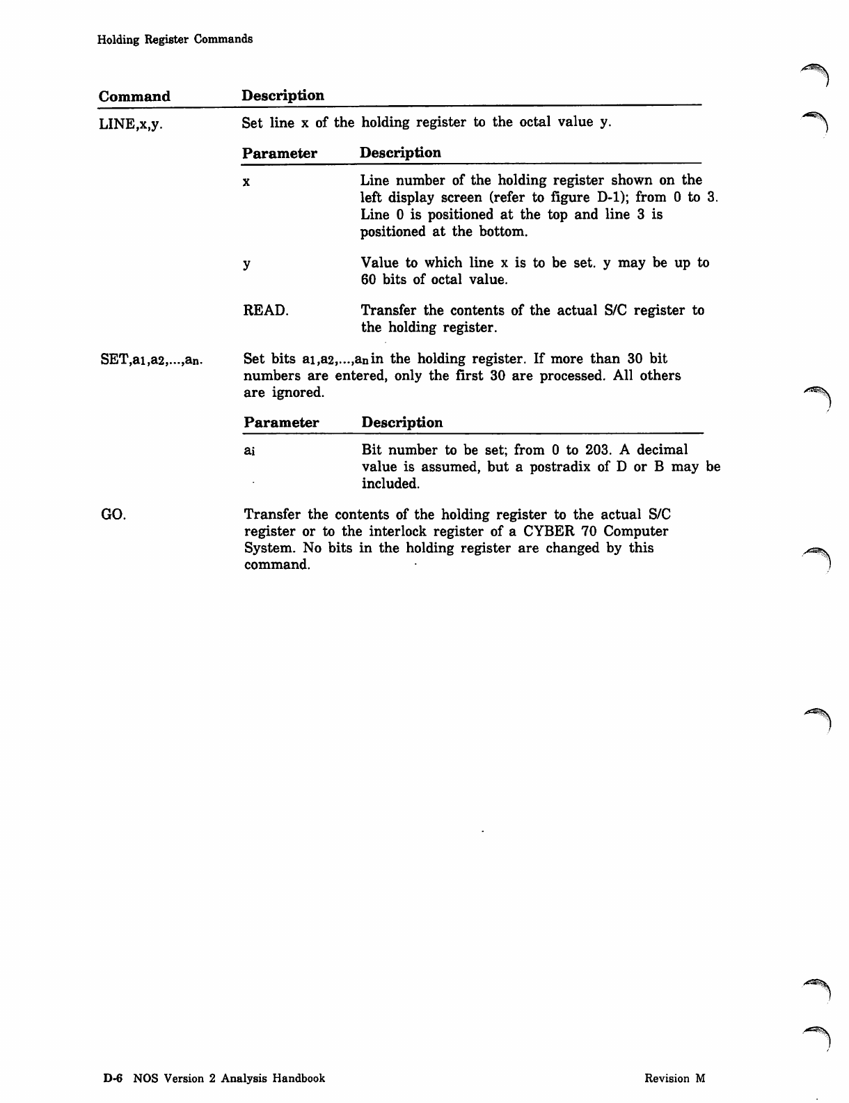
Holding Register Commands
Command
LINE,x,y.
Description
Set line x of the holding register to the octal value y.
Parameter Description
Line number of the holding register shown on the
left display screen (refer to figure D-l); from 0 to 3.
Line 0 is positioned at the top and line 3 is
positioned at the bottom.
Value to which line x is to be set. y may be up to
60 bits of octal value.
SET,ai,a2,...,an.
READ. Transfer the contents of the actual S/C register to
the holding register.
Set bits ai,a2,...,anin the holding register. If more than 30 bit
numbers are entered, only the first 30 are processed. All others
are ignored.
Parameter Description
ai Bit number to be set; from 0 to 203. A decimal
value is assumed, but a postradix of D or B may be
included.
GO. Transfer the contents of the holding register to the actual S/C
register or to the interlock register of a CYBER 70 Computer
System. No bits in the holding register are changed by this
command.
D-6 NOS Version 2 Analysis Handbook Revision M
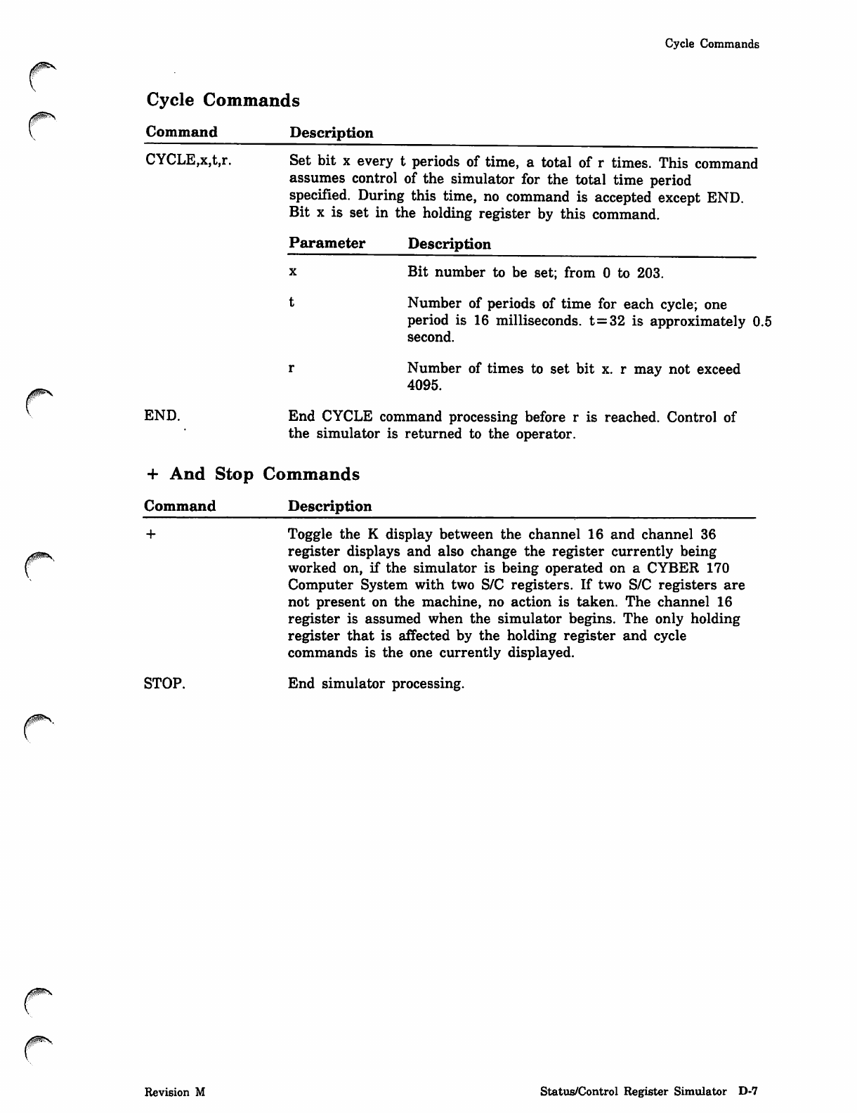
Cycle Commands
Cycle Commands
Command Description
CYCLE,x,t,r.
END.
Set bit x every t periods of time, a total of r times. This command
assumes control of the simulator for the total time period
specified. During this time, no command is accepted except END.
Bit x is set in the holding register by this command.
Parameter Description
x B i t n u m b e r t o b e s e t ; f r o m 0 t o 2 0 3 .
t Number of periods of time for each cycle; one
period is 16 milliseconds. t=32 is approximately 0.5
second.
r Number of times to set bit x. r may not exceed
4095.
End CYCLE command processing before r is reached. Control of
the simulator is returned to the operator.
+ And Stop Commands
Command Description
+
j0P**S
STOP.
Toggle the K display between the channel 16 and channel 36
register displays and also change the register currently being
worked on, if the simulator is being operated on a CYBER 170
Computer System with two S/C registers. If two S/C registers are
not present on the machine, no action is taken. The channel 16
register is assumed when the simulator begins. The only holding
register that is affected by the holding register and cycle
commands is the one currently displayed.
End simulator processing.
0$ms
Revision M Status/Control Register Simulator D-7

0^.
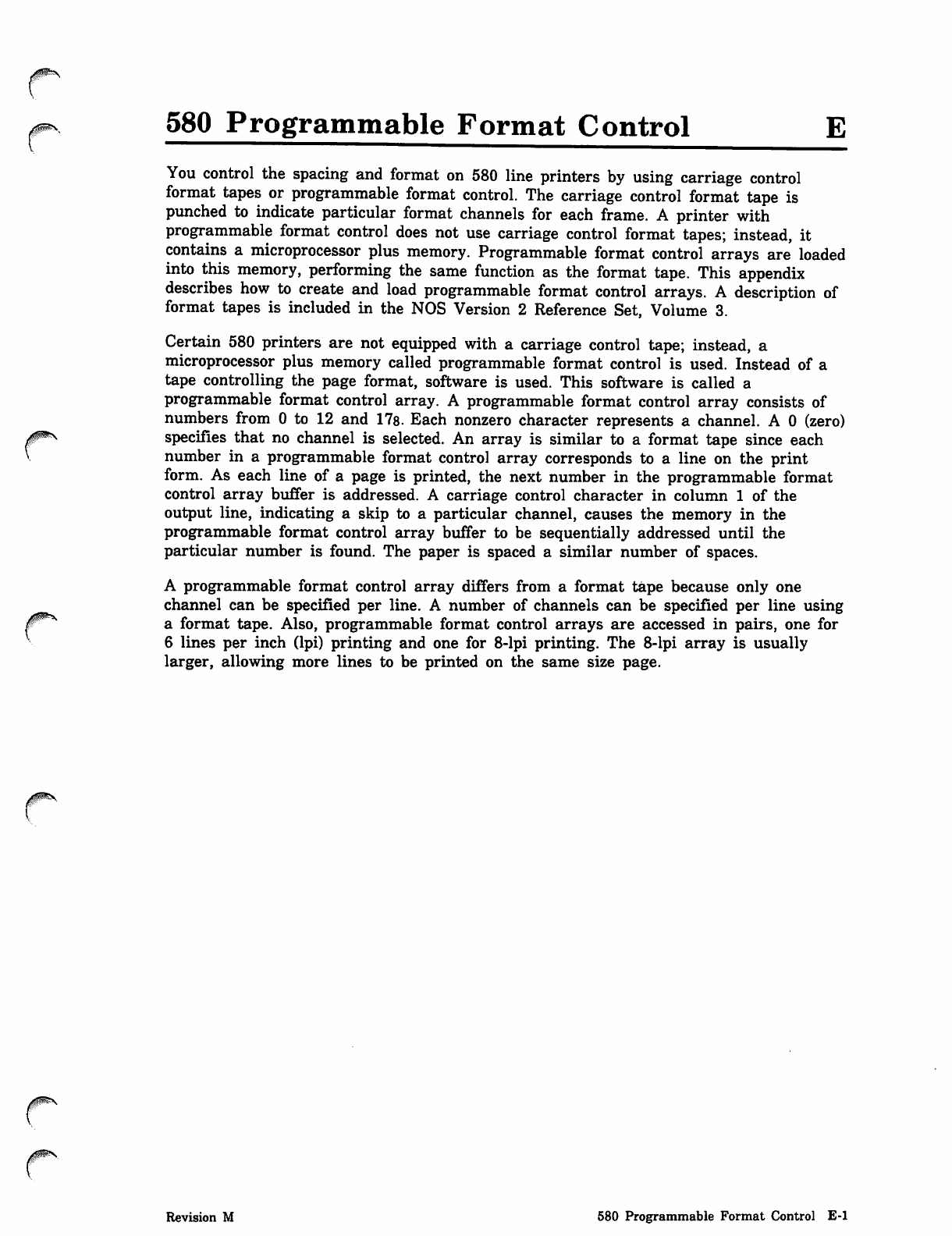
0$m\
580 Programmable Format Control E
You control the spacing and format on 580 line printers by using carriage control
format tapes or programmable format control. The carriage control format tape is
punched to indicate particular format channels for each frame. A printer with
programmable format control does not use carriage control format tapes; instead, it
contains a microprocessor plus memory. Programmable format control arrays are loaded
into this memory, performing the same function as the format tape. This appendix
describes how to create and load programmable format control arrays. A description of
format tapes is included in the NOS Version 2 Reference Set, Volume 3.
Certain 580 printers are not equipped with a carriage control tape; instead, a
microprocessor plus memory called programmable format control is used. Instead of a
tape controlling the page format, software is used. This software is called a
programmable format control array. A programmable format control array consists of
numbers from 0 to 12 and 17s. Each nonzero character represents a channel. A 0 (zero)
specifies that no channel is selected. An array is similar to a format tape since each
number in a programmable format control array corresponds to a line on the print
form. As each line of a page is printed, the next number in the programmable format
control array buffer is addressed. A carriage control character in column 1 of the
output line, indicating a skip to a particular channel, causes the memory in the
programmable format control array buffer to be sequentially addressed until the
particular number is found. The paper is spaced a similar number of spaces.
A programmable format control array differs from a format tape because only one
channel can be specified per line. A number of channels can be specified per line using
a format tape. Also, programmable format control arrays are accessed in pairs, one for
6 lines per inch dpi) printing and one for 8-lpi printing. The 8-lpi array is usually
larger, allowing more lines to be printed on the same size page.
Revision M 580 Programmable Format Control E-l
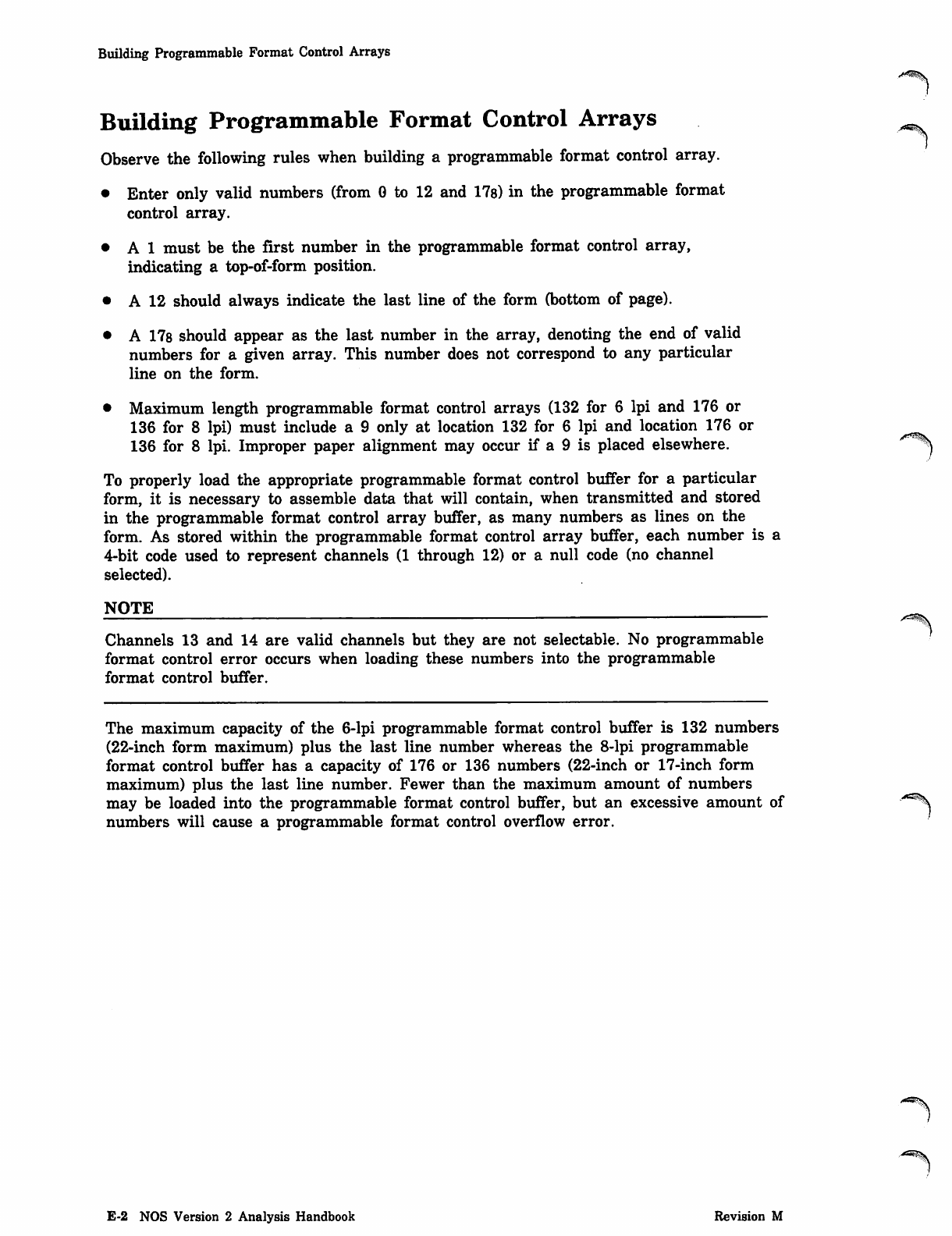
Building Programmable Format Control Arrays
Building Programmable Format Control Arrays
Observe the following rules when building a programmable format control array.
• Enter only valid numbers (from 0 to 12 and 17s) in the programmable format
control array.
• A 1 must be the first number in the programmable format control array,
indicating a top-of-form position.
• A 12 should always indicate the last line of the form (bottom of page).
• A 178 should appear as the last number in the array, denoting the end of valid
numbers for a given array. This number does not correspond to any particular
line on the form.
• Maximum length programmable format control arrays (132 for 6 lpi and 176 or
136 for 8 lpi) must include a 9 only at location 132 for 6 lpi and location 176 or
136 for 8 lpi. Improper paper alignment may occur if a 9 is placed elsewhere.
To properly load the appropriate programmable format control buffer for a particular
form, it is necessary to assemble data that will contain, when transmitted and stored
in the programmable format control array buffer, as many numbers as lines on the
form. As stored within the programmable format control array buffer, each number is a
4-bit code used to represent channels (1 through 12) or a null code (no channel
selected).
NOTE
Channels 13 and 14 are valid channels but they are not selectable. No programmable
format control error occurs when loading these numbers into the programmable
format control buffer.
The maximum capacity of the 6-lpi programmable format control buffer is 132 numbers
(22-inch form maximum) plus the last line number whereas the 8-lpi programmable
format control buffer has a capacity of 176 or 136 numbers (22-inch or 17-inch form
maximum) plus the last line number. Fewer than the maximum amount of numbers
may be loaded into the programmable format control buffer, but an excessive amount of ye^
numbers will cause a programmable format control overflow error.
E-2 NOS Version 2 Analysis Handbook Revision M
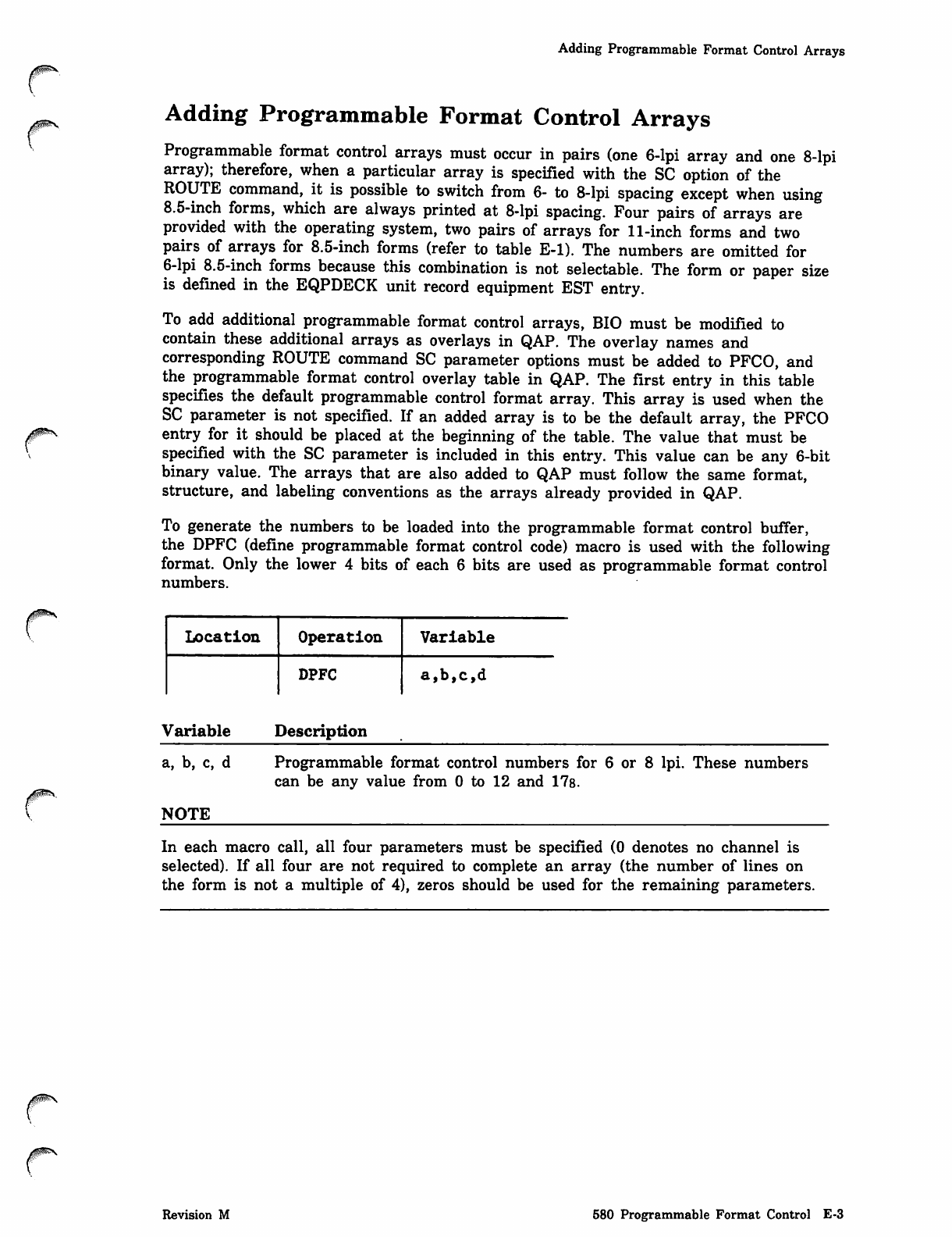
Adding Programmable Format Control Arrays
/Jpfcr^V
r
Adding Programmable Format Control Arrays
Programmable format control arrays must occur in pairs (one 6-lpi array and one 8-lpi
array); therefore, when a particular array is specified with the SC option of the
ROUTE command, it is possible to switch from 6- to 8-lpi spacing except when using
8.5-inch forms, which are always printed at 8-lpi spacing. Four pairs of arrays are
provided with the operating system, two pairs of arrays for 11-inch forms and two
pairs of arrays for 8.5-inch forms (refer to table E-l). The numbers are omitted for
6-lpi 8.5-inch forms because this combination is not selectable. The form or paper size
is defined in the EQPDECK unit record equipment EST entry.
To add additional programmable format control arrays, BIO must be modified to
contain these additional arrays as overlays in QAP. The overlay names and
corresponding ROUTE command SC parameter options must be added to PFCO, and
the programmable format control overlay table in QAP. The first entry in this table
specifies the default programmable control format array. This array is used when the
SC parameter is not specified. If an added array is to be the default array, the PFCO
entry for it should be placed at the beginning of the table. The value that must be
specified with the SC parameter is included in this entry. This value can be any 6-bit
binary value. The arrays that are also added to QAP must follow the same format,
structure, and labeling conventions as the arrays already provided in QAP.
To generate the numbers to be loaded into the programmable format control buffer,
the DPFC (define programmable format control code) macro is used with the following
format. Only the lower 4 bits of each 6 bits are used as programmable format control
numbers.
Location Operation Variable
DPFC a,b,c,d
Variable Description
a, b, c, d
NOTE
Programmable format control numbers for 6 or 8 lpi. These numbers
can be any value from 0 to 12 and 17s.
In each macro call, all four parameters must be specified (0 denotes no channel is
selected). If all four are not required to complete an array (the number of lines on
the form is not a multiple of 4), zeros should be used for the remaining parameters.
Revision M 580 Programmable Format Control E-3
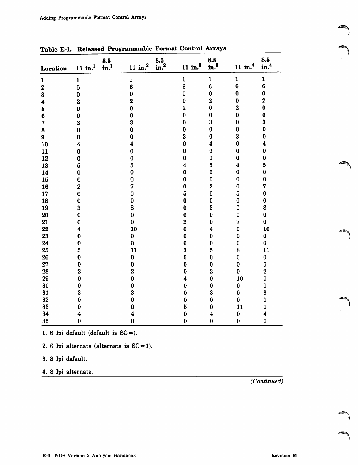
Adding Programmable Format Control Arrays
Table E-l. Released Programmable Format Control Arrays
8.5 8.5 8.5 8.5
Location 11 in.1
1
in.1 11 in.2 in.2 11 in.3 in. 11 in.4 in 4
in.
11 1 1 1 1
2 6 66 6 6 6
3 0 0 0 0 0 0
4 2 2 0 2 0 2
5 0 0 202 0
6 0 0 0 0 0 0
7330 3 0 3
8000 0 0 0
9 0 0 3 0 3 0
10
11
12
13
14
15
16
17
18
19
20
21
22 10 10
23
24
25 11 11
26
27
28
29 10
30
31
32
33 11
34
35
1. 6 lpi default (default is SC=).
2. 6 lpi alternate (alternate is SC = 1).
3. 8 lpi default.
4. 8 lpi alternate.
/*CIS$\
(Continued)
>as^\
E-4 NOS Version 2 Analysis Handbook Revision M
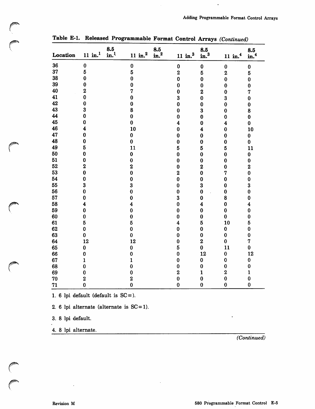
Adding Programmable Format Control Arrays
Table E-l. Released Programmable Format Control Arrays (Continued)
8.5
Location 11 in.1 in.1
36
37
38
39
40
41
42
43
44
45
46
47
48
49
50
51
52
53
54
55
56
57
58
59
60
61
62
63
64 12
65
66
67
68
69
70
71
8.5
11 in.2 in.2
0
5
0
0
7
0
0
8
0
0
10
0
0
11
0
0
2
0
0
3
0
0
4
0
0
5
0
0
12
0
0
1
0
0
2
0
8.5
11 in.3 in.3
1. 6 lpi default (default is SC = ).
2. 6 lpi alternate (alternate is SC = 1).
3. 8 lpi default.
4. 8 lpi alternate.
8.5
11 in.4 in.4
0 0 0 0
2525
0000
0000
0 2 0 7
3030
0000
0308
0000
4 0 4 0
0 4 0 10
00 0 0
0 0 0 0
5 5 5 11
0 0 0 0
0 0 0 0
0 2 0 2
2 0 7 0
0 0 0 0
0 3 0 3
0 0 0 0
3 0 8 0
0 4 0 4
0 0 0 0
0 0 0 0
4 5 10
0 0 0
0 0 0
0 2 0
5 0 11
012 12
0 0 0 0
0 0 0 0
2121
0000
0 0 0 0
(Continued)
/§SSN
Revision M 580 Programmable Format Control E-5
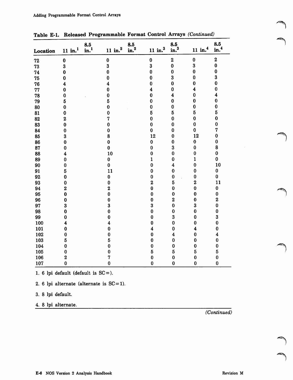
Adding Programmable Format Control Arrays
Table E-l. Released Programmable Format Control Arrays (Continued)
Location
8.5
11 in.1 in.1
72
73
74
75
76
77
78
79
80
81
82
83
84
85
86
87
88
89
90
91
92
93
94
95
96
97
98
99
100
101
102
103
104
105
106
107
11 in.2
8.5
in.
8.5
11 in.3 in.3
1. 6 lpi default (default is SC=).
2. 6 lpi alternate (alternate is SC = 1).
3. 8 lpi default.
4. 8 lpi alternate.
8.5
11 in.4 in.4
0 0 2 0 2
3 3 030
0 0 000
0 0 3 0 3
4 0 0 0 0
04040
00 4 0 4
5 0 0 0 0
0 000 0
0 555 5
7 0 0 0 0
00 0 0 0
0 0 0 0 7
812 12
0 0 0 0
0 0 3 0
10
0
010
11
0
011
2 0 0 0 0
0 0 0 0 0
0 0 2 0 2
33 0 3 0
0 0 0 0 0
0 0 3 0 3
400 0 0
0 4 0 4 0
00 4 0 4
5 0 0 0 0
0 0 0 0 0
0 5 5 5 5
7 0 0 0 0
0 0 0 0 0
•"^^JV
(Continued)
E-6 NOS Version 2 Analysis Handbook Revision M
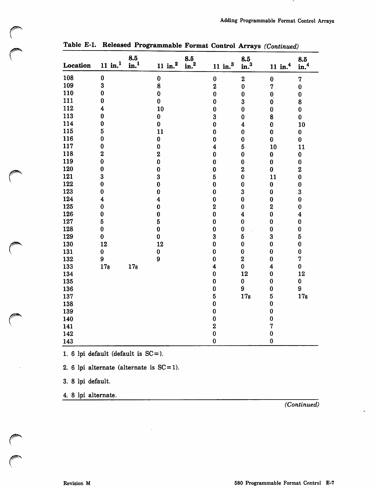
Adding Programmable Format Control Arrays
Table E-l. Released Programmable Format Control Arrays (Continued)
8.5 8.5 8.5 8.5
Location 11 in. in. 11 in.2 in.s5 1 1 i n . 3 in.3 11 in.4 in.4
108
109
110
111
112 10
113
114 10
115 11
116
117 10 11
118
119
120
121 11
122
123
124
125
126
127
128
129
130 12 12
131
132
133 178 178
134 12 12
135
136
137 178 178
138
139
140
141
142
143
1. 6 lpi default (default is SC = ).
2. 6 lpi alternate (alternate is SC = 1).
3. 8 lpi default.
4. 8 lpi alternate.
(Continued)
Revision M 580 Programmable Format Control E-7
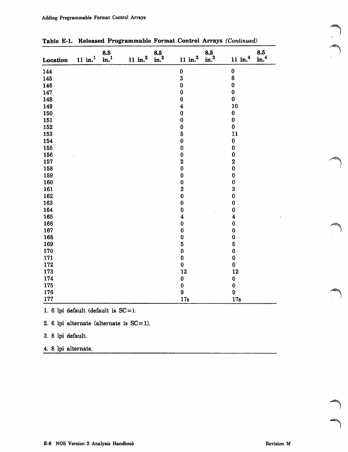
Adding Programmable Format Control Arrays
Table E-l. Released Programmable Format Control Arrays (Continued)
8.5 8.5 8.5 8.5
Location 11 in.1 i« i
in. 11 inu1 in 2
in. 11 in.3 in.3 11 in.4 * 4
in.
144
145
146
147
148
149 10
150
151
152
153 11
154
155
156
157
158
159
160
161
162
163
164
165
166
167
168
169
170
171
172
173 12 12
174
175
176
177 178 178
1. 6 lpi default (default is SC:= ).
2. 6 lpi alternate (alternate is SC = 1).
3. 8 lpi default.
4. 8 lpi alternate.
^-*»»iV
E-8 NOS Version 2 Analysis Handbook Revision M
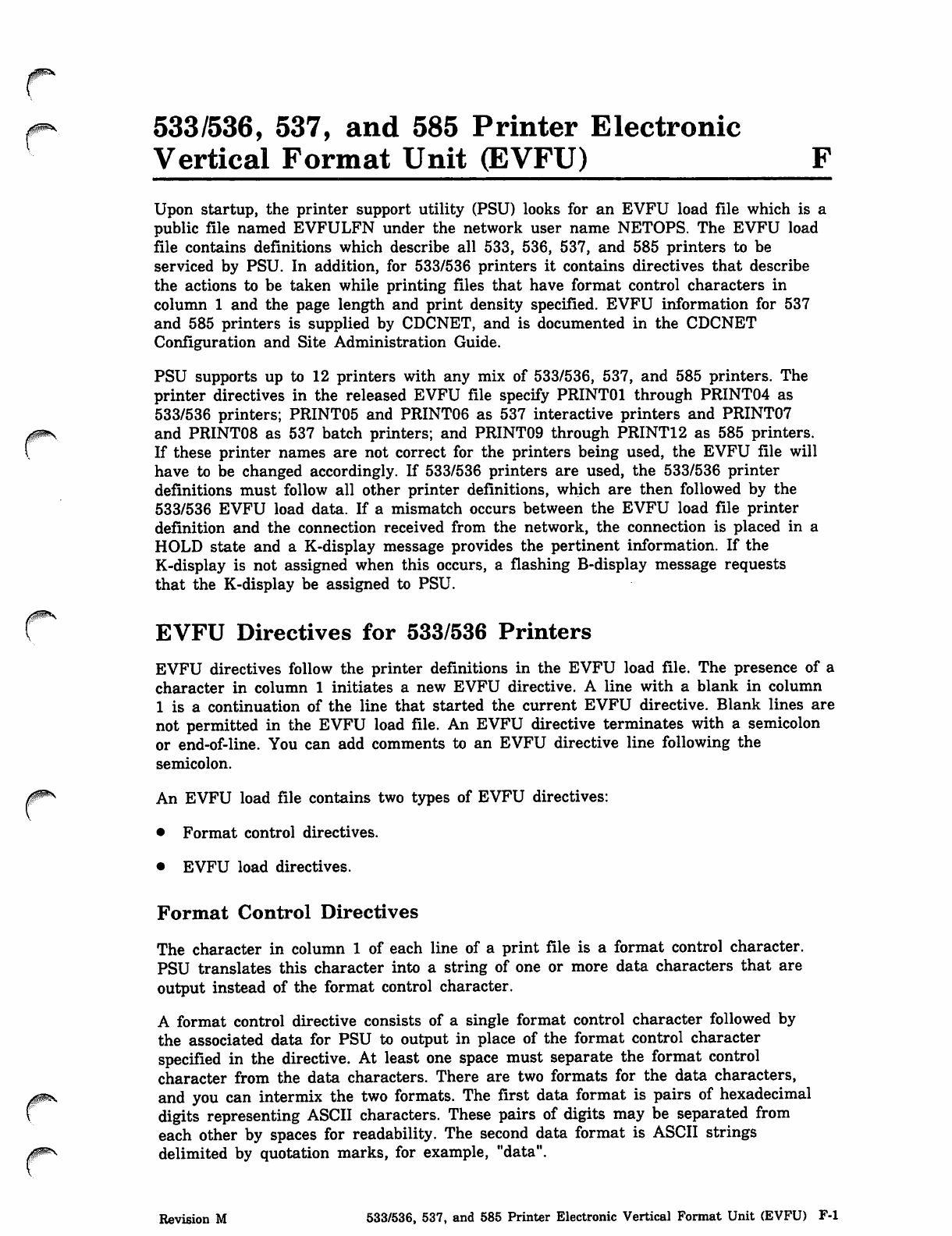
m*- 533/536, 537, and 585 Printer Electronic
Vertical Format Unit (EVFU) F
Upon startup, the printer support utility (PSU) looks for an EVFU load file which is a
public file named EVFULFN under the network user name NETOPS. The EVFU load
file contains definitions which describe all 533, 536, 537, and 585 printers to be
serviced by PSU. In addition, for 533/536 printers it contains directives that describe
the actions to be taken while printing files that have format control characters in
column 1 and the page length and print density specified. EVFU information for 537
and 585 printers is supplied by CDCNET, and is documented in the CDCNET
Configuration and Site Administration Guide.
PSU supports up to 12 printers with any mix of 533/536, 537, and 585 printers. The
printer directives in the released EVFU file specify PRINT01 through PRINT04 as
533/536 printers; PRINT05 and PRINT06 as 537 interactive printers and PRINT07
rand PRINT08 as 537 batch printers; and PRINT09 through PRINT12 as 585 printers.
If these printer names are not correct for the printers being used, the EVFU file will
have to be changed accordingly. If 533/536 printers are used, the 533/536 printer
definitions must follow all other printer definitions, which are then followed by the
533/536 EVFU load data. If a mismatch occurs between the EVFU load file printer
definition and the connection received from the network, the connection is placed in a
HOLD state and a K-display message provides the pertinent information. If the
K-display is not assigned when this occurs, a flashing B-display message requests
that the K-display be assigned to PSU.
rEVFU Directives for 533/536 Printers
EVFU directives follow the printer definitions in the EVFU load file. The presence of a
character in column 1 initiates a new EVFU directive. A line with a blank in column
1 is a continuation of the line that started the current EVFU directive. Blank lines are
not permitted in the EVFU load file. An EVFU directive terminates with a semicolon
or end-of-line. You can add comments to an EVFU directive line following the
semicolon.
An EVFU load file contains two types of EVFU directives:
• Format control directives.
• EVFU load directives.
Format Control Directives
The character in column 1 of each line of a print file is a format control character.
PSU translates this character into a string of one or more data characters that are
output instead of the format control character.
A format control directive consists of a single format control character followed by
the associated data for PSU to output in place of the format control character
specified in the directive. At least one space must separate the format control
character from the data characters. There are two formats for the data characters,
and you can intermix the two formats. The first data format is pairs of hexadecimal
digits representing ASCII characters. These pairs of digits may be separated from
each other by spaces for readability. The second data format is ASCII strings
delimited by quotation marks, for example, "data".
Revision M 533/536, 537, and 585 Printer Electronic Vertical Format Unit (EVFU) F-l
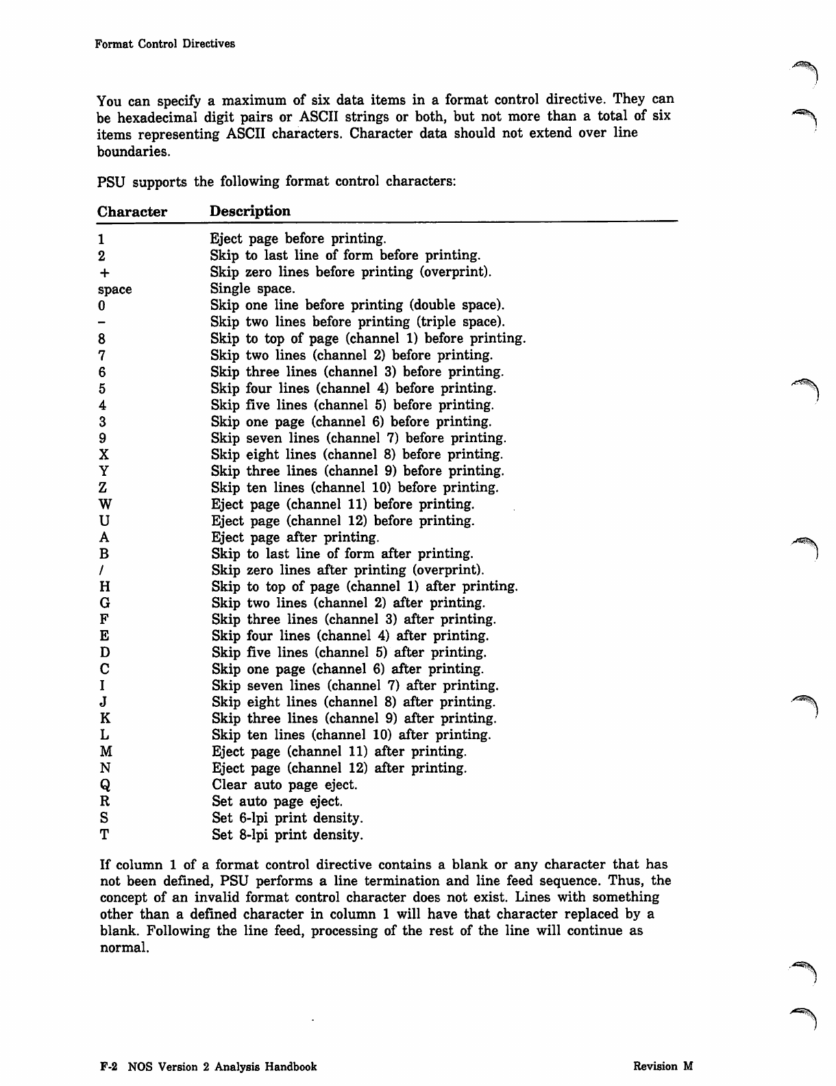
Format Control Directives
You can specify a maximum of six data items in a format control directive. They can
be hexadecimal digit pairs or ASCII strings or both, but not more than a total of six
items representing ASCII characters. Character data should not extend over line
boundaries.
PSU supports the following format control characters:
Character
1
2
+
space
0
8
7
6
5
4
3
9
X
Y
Z
w
u
A
B
/
H
G
F
E
D
C
I
J
K
L
M
N
Q
R
S
T
Description
Eject page before printing.
Skip to last line of form before printing.
Skip zero lines before printing (overprint).
Single space.
Skip one line before printing (double space).
Skip two lines before printing (triple space).
Skip to top of page (channel 1) before printing.
Skip two lines (channel 2) before printing.
Skip three lines (channel 3) before printing.
Skip four lines (channel 4) before printing.
Skip five lines (channel 5) before printing.
Skip one page (channel 6) before printing.
Skip seven lines (channel 7) before printing.
Skip eight lines (channel 8) before printing.
Skip three lines (channel 9) before printing.
Skip ten lines (channel 10) before printing.
Eject page (channel 11) before printing.
Eject page (channel 12) before printing.
Eject page after printing.
Skip to last line of form after printing.
Skip zero lines after printing (overprint).
Skip to top of page (channel 1) after printing.
Skip two lines (channel 2) after printing.
Skip three lines (channel 3) after printing.
Skip four lines (channel 4) after printing.
Skip five lines (channel 5) after printing.
Skip one page (channel 6) after printing.
Skip seven lines (channel 7) after printing.
Skip eight lines (channel 8) after printing.
Skip three lines (channel 9) after printing.
Skip ten lines (channel 10) after printing.
Eject page (channel 11) after printing.
Eject page (channel 12) after printing.
Clear auto page eject.
Set auto page eject.
Set 6-lpi print density.
Set 8-lpi print density.
A?*£%S
If column 1 of a format control directive contains a blank or any character that has
not been defined, PSU performs a line termination and line feed sequence. Thus, the
concept of an invalid format control character does not exist. Lines with something
other than a defined character in column 1 will have that character replaced by a
blank. Following the line feed, processing of the rest of the line will continue as
normal.
■**\
F-2 NOS Version 2 Analysis Handbook Revision M
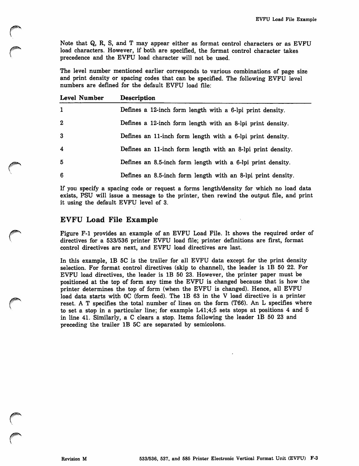
0ims
0^s
EVFU Load File Example
Note that Q, R, S, and T may appear either as format control characters or as EVFU
load characters. However, if both are specified, the format control character takes
precedence and the EVFU load character will not be used.
The level number mentioned earlier corresponds to various combinations of page size
and print density or spacing codes that can be specified. The following EVFU level
numbers are defined for the default EVFU load file:
Level Number Description
1 Defi ne s a 12 -in ch fo rm len gt h w it h a 6- l pi pr in t d e ns it y.
2 Defines a 12-inch form length with an 8-lpi print density.
3 D efi nes an 11-i nc h f o rm le n gt h w i th a 6 -l p i p ri nt den sit y.
4 Defines an 11-inch form length with an 8-lpi print density.
5 Defines an 8.5-inch form length with a 6-lpi print density.
6 Defines an 8.5-inch form length with an 8-lpi print density.
If you specify a spacing code or request a forms length/density for which no load data
exists, PSU will issue a message to the printer, then rewind the output file, and print
it using the default EVFU level of 3.
EVFU Load File Example
Figure F-l provides an example of an EVFU Load File. It shows the required order of
directives for a 533/536 printer EVFU load file; printer definitions are first, format
control directives are next, and EVFU load directives are last.
In this example, IB 5C is the trailer for all EVFU data except for the print density
selection. For format control directives (skip to channel), the leader is IB 50 22. For
EVFU load directives, the leader is IB 50 23. However, the printer paper must be
positioned at the top of form any time the EVFU is changed because that is how the
printer determines the top of form (when the EVFU is changed). Hence, all EVFU
load data starts with OC (form feed). The IB 63 in the V load directive is a printer
reset. A T specifies the total number of lines on the form (T66). An L specifies where
to set a stop in a particular line; for example L41;4;5 sets stops at positions 4 and 5
in line 41. Similarly, a C clears a stop. Items following the leader IB 50 23 and
preceding the trailer IB 5C are separated by semicolons.
Revision M 533/536, 537, and 585 Printer Electronic Vertical Format Unit (EVFU) F-3
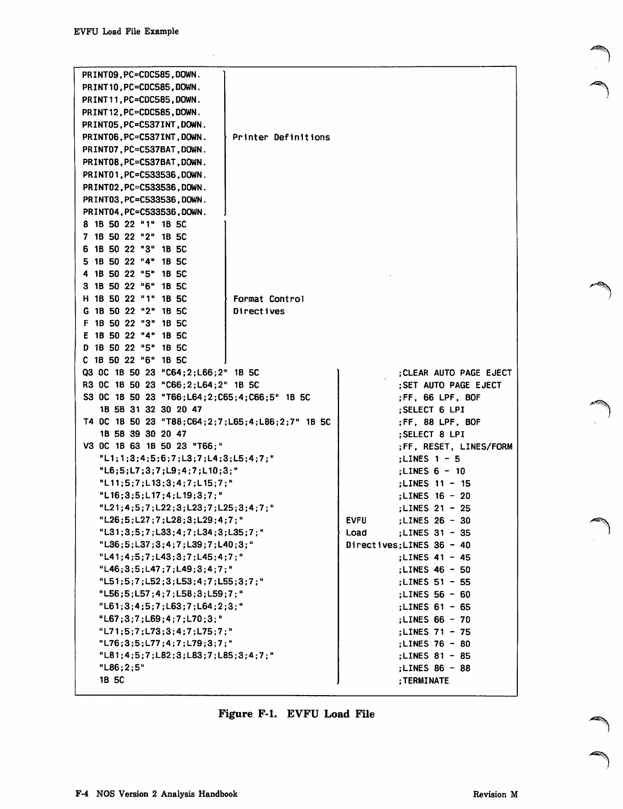
EVFU Load File Example
PRINT09,PC=CDC585,DOWN.
PRINT10,PC=CDC585,DOWN.
PRINT11,PC=CDC585,DOWN.
PRINT12,PC=CDC585,DOWN.
PRINT05,PC=C537INT,DOWN.
PRINT06,PC=C537INT,DOWN. Printer Definitions
PRINT07,PC=C537BAT,DOWN.
PRINT08,PC=C537BAT,DOWN.
PRINT01,PC=C533536,DOWN.
PRINT02,PC=C533536,DOWN.
PRINT03,PC=C533536,DOWN.
PRINT04,PC=C533536,DOWN.
8 1B 50 22 "1" 1B 5C
7 1B 50 22 "2" 1B 5C
6 1B 50 22 "3" 1B 5C
5 1B 50 22 "4" 1B 5C
4 IB 50 22 "5" 1B 5C
3 1B 50 22 °6H 1B 5C
H IB 50 22 "1" 1B 5C Format Control
G 1B 50 22 "2" 1B 5C D i r e c t i v e s
F 1B 50 22 "3" IB 5C
E 1B 50 22 "4° 1B 5C
D 1B 50 22 "5" 1B 5C
C 1B 50 22 "6" 1B 5C
Q 3 O C 1 B 5 0 2 3 " C 6 4 ; 2 ; L 6 6 ; 2 " 1 B 5 C 1 CLEAR AUTO PAGE EJECT
R3 OC 1B 50 23 "C66;2;L64;2" 1B 5C SET AUTO PAGE EJECT
S3 OC 1B 50 23 "T66;L64;2;C65;4;C66;5" 1B 5C FF, 66 LPF, BOF
IB 5B 31 32 30 20 47 SELECT 6 LPI
T4 OC 1B 50 23 MT88;C64;2;7;L65;4;L86;2;7" 1B 5C FF, 88 LPF, BOF
1B 5B 39 30 20 47 SELECT 8 LPI
V3 OC 1B 63 1B 50 23 "T66;" FF, RESET, LINES/FORM
"L1;1;3;4;5;6;7;L3;7;L4;3;L5;4;7;" LINES 1 - 5
"L6;5;L7;3;7;L9;4;7;L10;3;" LINES 6-10
"L11 5;7;L13;3;4;7;L15;7;" LINES 11-15
"L16 3;5;L17;4;L19;3;7;" LINES 16 - 20
"L21 4;5;7;L22;3;L23;7;L25;3;4;7;" LINES 21 - 25
"L26 5;L27;7;L28;3;L29;4;7;" EVFU LINES 26 - 30
"L31 3;5;7;L33;4;7;L34;3;L35;7;" Load LINES 31 - 35
"L36 5;L37;3;4;7;L39;7;L40;3;" Directives LINES 36 - 40
UL41 4;5;7;L43;3;7;L45;4;7;,, LINES 41 - 45
"L46 3;5;L47;7;L49;3;4;7;" LINES 46 - 50
"L51 5;7;L52;3;L53;4;7;L55;3;7;U LINES 51 - 55
"L56 5;L57;4;7;L58;3;L59;7;" LINES 56 - 60
"L61 3;4;5;7;L63;7;L64;2;3;" LINES 61 - 65
"L67 3; 7 ;L69 ; 4;7 ; L70 ; 3;" LINES 66 - 70
"L71 5;7;L73;3;4;7;L75;7;" LINES 71 - 75
"L76 3;5;L77;4;7;L79;3;7;U LINES 76 - 80
"L81 4;5;7;L82;3;L83;7;L85;3;4;7;" LINES 81-85
"L86 2;5" LINES 86 - 88
1 B 5 C J TERMINATE
Figure F-l. EVFU Load File
F-4 NOS Version 2 Analysis Handbook Revision M
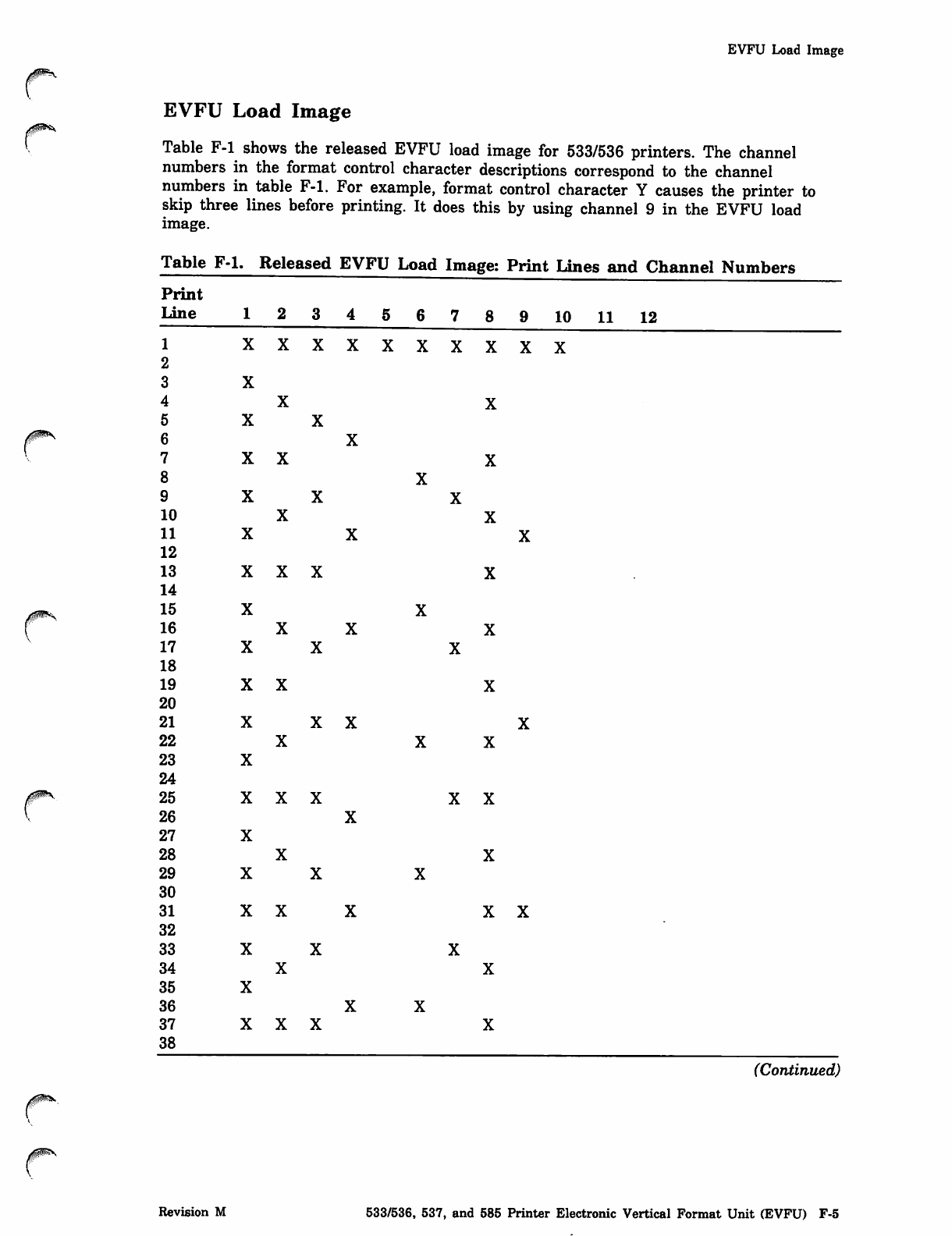
EVFU Load Image
EVFU Load Image
Table F-l shows the released EVFU load image for 533/536 printers. The channel
numbers in the format control character descriptions correspond to the channel
numbers in table F-l. For example, format control character Y causes the printer to
skip three lines before printing. It does this by using channel 9 in the EVFU load
image.
Table F-l. Released EVFU Load Image: Print Lines and Channel Numbers
Print
Line 123456789 10 11 12
1 xxxxxxxxxx
2
3 X
4 X X
5 X X
6 X
7 X X X
8 X
9 X X X
1 0 X X
1 1 X X X
12
1 3 X X X X
14
1 5 X X
1 6 X X X
1 7 X X X
18
1 9 X X X
20
2 1 X X X X
2 2 X X X
2 3 X
24
2 5 X X X X X
2 6 X
2 7 X
2 8 X X
2 9 X X X
30
3 1 X X X X X
32
3 3 X X X
3 4 X X
3 5 X
3 6 X X
3 7 X X X X
38
(Continued)
Revision M 533/536, 537, and 585 Printer Electronic Vertical Format Unit (EVFU) F-5
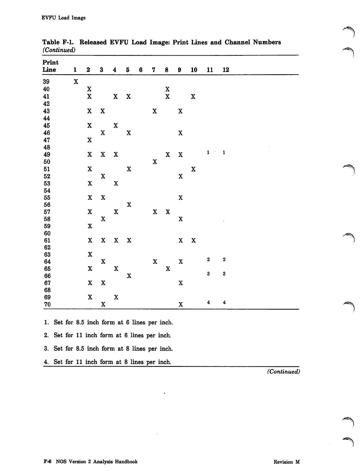
EVFU Load Image
Table F-l. Released EVFU Load Image: Print Lines and Channel Numbers
(Continued)
Print
Line 123456789 10 11 12
39
40
41
42
43
44
45
46
47
48
49
50
51
52
53
54
55
56
57
58
59
60
61
62
63
64
65
66
67
68
69
70
1. Set for 8.5 inch form at 6 lines per inch.
2. Set for 11 inch form at 6 lines per inch.
3. Set for 8.5 inch form at 8 lines per inch.
4. Set for 11 inch form at 8 lines per inch.
(Continued)
F-6 NOS Version 2 Analysis Handbook Revision M
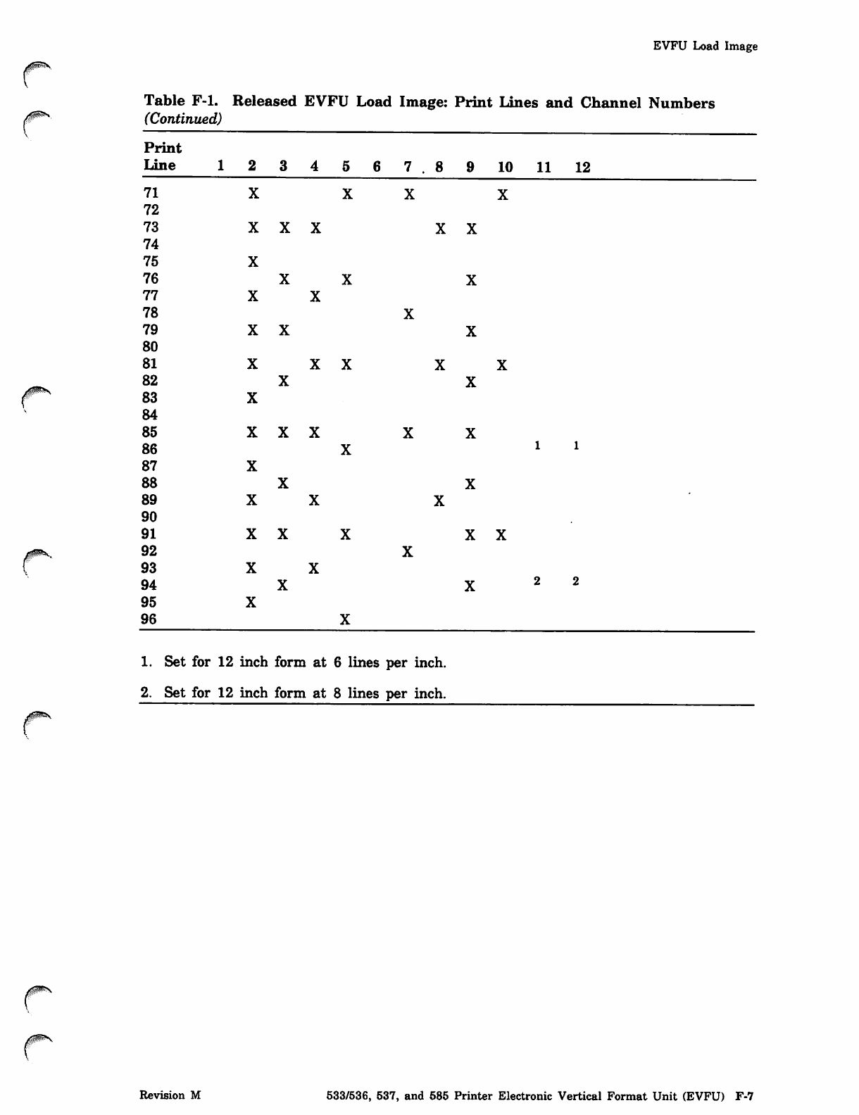
EVFU Load Image
0SrS,
Table F-l. Released EVFU Load Image: Print Lines and Channel Numbers
/SiiS*», (Continued)
V
Print
L i n e 1 7 . 1 0 1 1 1 2
71
72
73
74
75
76
77
78
79
80
81
82
^ms 83
y. 84
85
86 l l
87
88
89
90
91
/ffNsftrt^ 92
{93
94 2 2
95
96
1. Set for 12 inch form at 6 lines per inch.
2. Set for 12 inch form at 8 lines per inch.
Revision M 533/536, 537, and 585 Printer Electronic Vertical Format Unit (EVFU) F-7

00&S
881/883 Pack Reformatting Utility G
Each 881 disk pack used in the 844 disk contains factory-recorded flawing information
on cylinder 6328 (410), track 0, sectors 0, 1, and 2. Each 883 pack contains this
information on cylinder 14668 (822), track 0, sectors 0, 1, and 2. The following
information is included on the cylinders.
•
•
•
Cylinder 6328 (or 1466s for 883 packs), track 0, sector 0 contains the
factory-recorded manufacturing data. This data consists of the pack serial number
and the manufacturing date.
Cylinder 6328 (or 1466s), track 0, sector 1 contains the factory map. This map
contains a list of all factory-detected flaws, both correctable and uncorrectable.
Cylinder 6328 (or 1466s), track 0, sector 2 contains the utility map. This map
originally contains all factory-detected uncorrectable flaws. This map is updated by
the reformatting utility.
FORMAT is a CPU program that operates in conjunction with FDP, a PP program, to
maintain and reformat 881/883 disk packs. It is used to perform the following
functions.
• Factory-recorded manufacturing data, factory-recorded flaw data, and utility flaw
data can be retrieved from a factory-formatted disk pack.
• Sector and track flaws can be set or cleared on a factory-formatted disk pack.
• Address fields of a previously factory-formatted disk pack can be restored. (This
function is used only in the event that addresses on the pack are lost.)
In order to function, FORMAT requires that the factory-recorded data [sectors 0 and 1
of cylinder 6328 (or 1466s)] be correct and readable. The pack cannot be processed if
this data is unreadable. If packs are available that do not contain this factory-recorded
information, consult a customer engineer to have this information placed on the packs.
Also, the correct level of controlware must be present in order for FORMAT to
function. To determine the controlware level and for procedures to install this
controlware, refer to the NOS Version 2 Installation Handbook. Since the operating
system requires that the utility map contain the physical flaw information in order for
automatic logical flawing to be performed, it is important that the utility map be
properly maintained.
The operating system automatically sets logical flaws when initializing 844
equipment. This is done by reading the utility map of the 844 units involved, and
mapping this physical flaw information into the corresponding logical track addresses.
Logical track flaw reservations are then made in the track reservation table (TRT)
for the 844 equipment being installed. For example, if the 844 equipment being
initialized consists of two physical units (such as a DI-2 configuration), the logical
flaws set in the TRT are obtained from the physical flaw information recorded in the
utility maps of both units making up the DI-2 configuration. This automatic flawing
occurs when an equipment is initialized, regardless of whether the initialization is
done during deadstart or online. Automatic flawing also occurs when an X.FLAW
request is made from the console.
Revision M 881/883 Pack Reformatting Utility G-l
FORMAT Command
The operating system allows for setting and clearing flaw information. The SLF and
CLF APRDECK entries set or clear logical track reservations in the TRT of the ^\
equipment. (Refer to section 3, Deadstart Decks, for information concerning these '
entries.) If the device is then checkpointed, this flaw information is preserved in the
TRT portion of the device label. The SLF entry can be made during deadstart, during
online initialization, or by using the FLAW utility (as described in section 8, K-Display
Utilities). In any case, the flawing done via these entries is only logical; the flaw
information remains only in the TRT and is discarded on subsequent deadstart
initialization. This information is also lost during online initializations if it was not
possible to recover the equipment. Using SLF does not cause any additional information
to be recorded in the utility map; only FORMAT is capable of updating the utility map
data. Caution should be used if attempts are made to cancel a logical flaw that was
made during automatic flawing, since the physical disk sector is still marked as flawed
and attempts to access that sector yield error conditions.
The use of the FORMAT utility for maintaining and reformatting 881/883 disk packs
is described next.
FORMAT Command
Processing maintenance operations on an 881/883 type disk pack is initiated by the
FORMAT command. This program interfaces with you as required. The format of this
command is:
FORMAT, Pi,p2,...,Pn-
Each pi is a keyword or a keyword equated to a value.
pi Description ____^___
G=m Relative unit of a multispindle device. This value is checked for
validity within the device. For example, if the device is a DI-2 and
G=2 is specified, an error results.
I=infile File on which input directives and data are written.
I Same as I=INPUT.
L=outfile Output file on which the information extracted from the disk pack
is to be written. (Refer to Output Formats later in this appendix.)
L S a m e a s L = O U T P U T .
G-2 NOS Version 2 Analysis Handbook Revision M
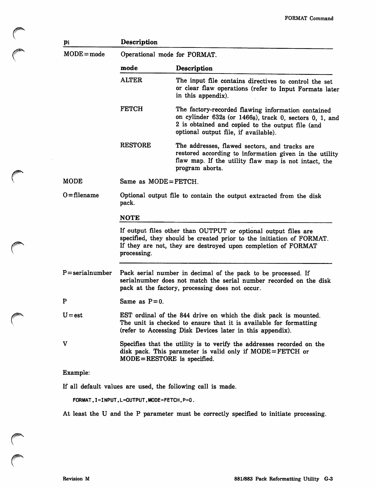
FORMAT Command
Pi
MODE
0=filename
Description
MODE=mode Operational mode for FORMAT.
mode Description
ALTER The input file contains directives to control the set
or clear flaw operations (refer to Input Formats later
in this appendix).
FETCH The factory-recorded flawing information contained
on cylinder 6328 (or 1466s), track 0, sectors 0, 1, and
2 is obtained and copied to the output file (and
optional output file, if available).
RESTORE The addresses, flawed sectors, and tracks are
restored according to information given in the utility
flaw map. If the utility flaw map is not intact, the
program aborts.
Same as MODE = FETCH.
Optional output file to contain the output extracted from the disk
pack.
NOTE
If output files other than OUTPUT or optional output files are
specified, they should be created prior to the initiation of FORMAT.
If they are not, they are destroyed upon completion of FORMAT
processing.
P = serialnumber Pack serial number in decimal of the pack to be processed. If
serialnumber does not match the serial number recorded on the disk
pack at the factory, processing does not occur.
P S a m e a s P = 0 .
U = est EST ordinal of the 844 drive on which the disk pack is mounted.
The unit is checked to ensure that it is available for formatting
(refer to Accessing Disk Devices later in this appendix).
V Specifies that the utility is to verify the addresses recorded on the
disk pack. This parameter is valid only if MODE = FETCH or
MODE=RESTORE is specified.
Example:
If all default values are used, the following call is made.
FORMAT,I=INPUT,L=0UTPUT,M0DE=FETCH,P=0.
At least the U and the P parameter must be correctly specified to initiate processing.
0ms
Revision M 881/883 Pack Reformatting Utility G-3
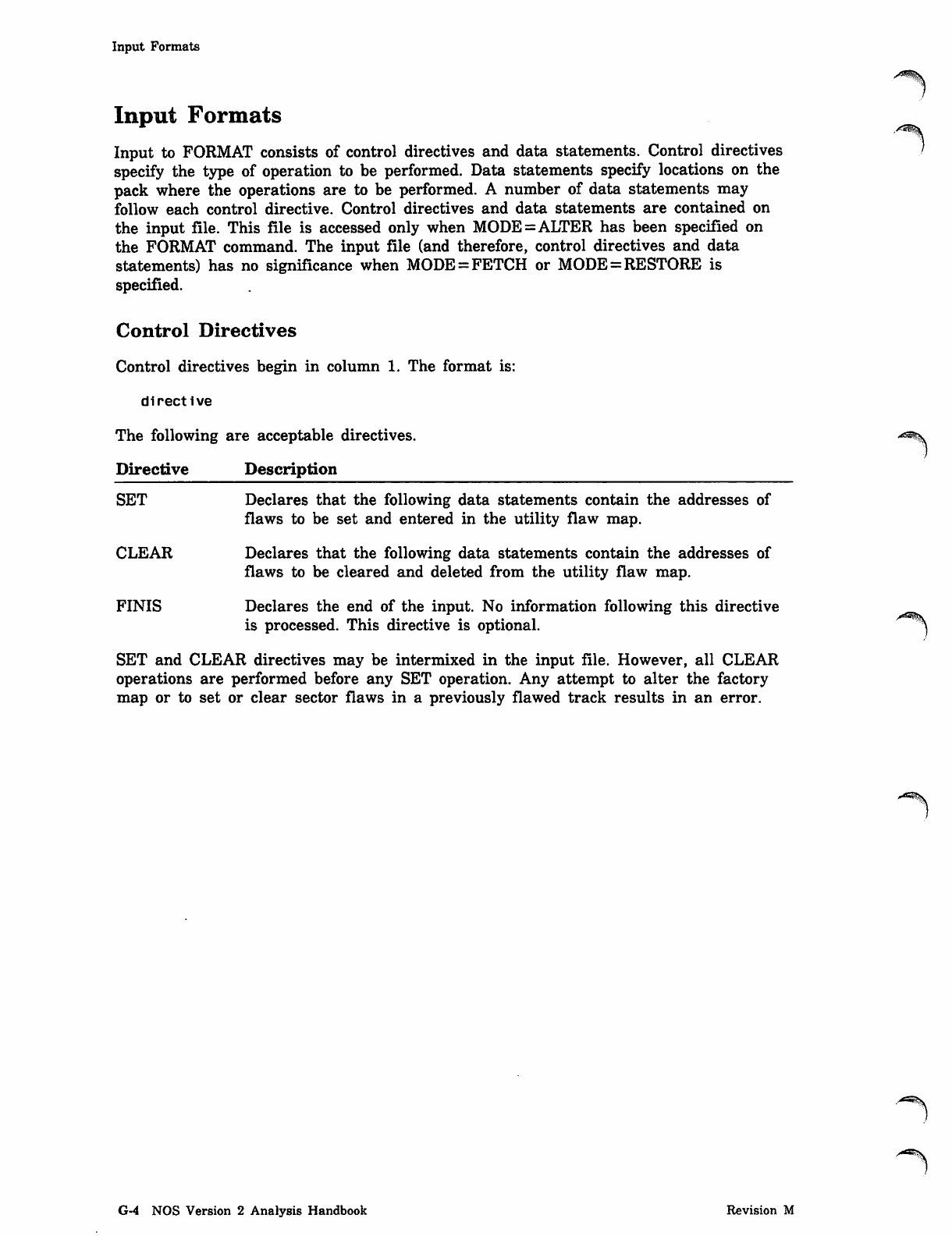
Input Formats
Input Formats
Input to FORMAT consists of control directives and data statements. Control directives
specify the type of operation to be performed. Data statements specify locations on the
pack where the operations are to be performed. A number of data statements may
follow each control directive. Control directives and data statements are contained on
the input file. This file is accessed only when MODE=ALTER has been specified on
the FORMAT command. The input file (and therefore, control directives and data
statements) has no significance when MODE = FETCH or MODE = RESTORE is
specified.
Control Directives
Control directives begin in column 1. The format is:
directive
The following are acceptable directives.
Directive Description
SET Declares that the following data statements contain the addresses of
flaws to be set and entered in the utility flaw map.
CLEAR Declares that the following data statements contain the addresses of
flaws to be cleared and deleted from the utility flaw map.
FINIS Declares the end of the input. No information following this directive
is processed. This directive is optional. ^
SET and CLEAR directives may be intermixed in the input file. However, all CLEAR
operations are performed before any SET operation. Any attempt to alter the factory
map or to set or clear sector flaws in a previously flawed track results in an error.
G-4 NOS Version 2 Analysis Handbook Revision M
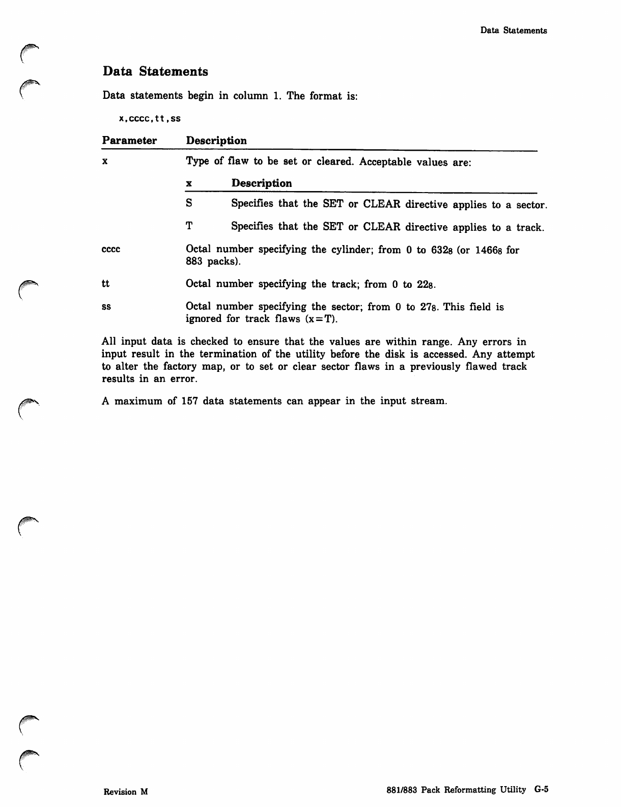
Data Statements
0ms
Data Statements
Data statements begin in column 1. The format is:
x.cccc.tt,ss
Parameter Description
x Type of flaw to be set or cleared. Acceptable values are:
x Description
S Specifies that the SET or CLEAR directive applies to a sector.
T Specifies that the SET or CLEAR directive applies to a track.
cccc Octal number specifying the cylinder; from 0 to 632s (or 1466s for
883 packs).
tt Octal number specifying the track; from 0 to 22s.
ss Octal number specifying the sector; from 0 to 27s. This field is
ignored for track flaws (x = T).
All input data is checked to ensure that the values are within range. Any errors in
input result in the termination of the utility before the disk is accessed. Any attempt
to alter the factory map, or to set or clear sector flaws in a previously flawed track
results in an error.
A maximum of 157 data statements can appear in the input stream.
Revision M 881/883 Pack Reformatting Utility G-5
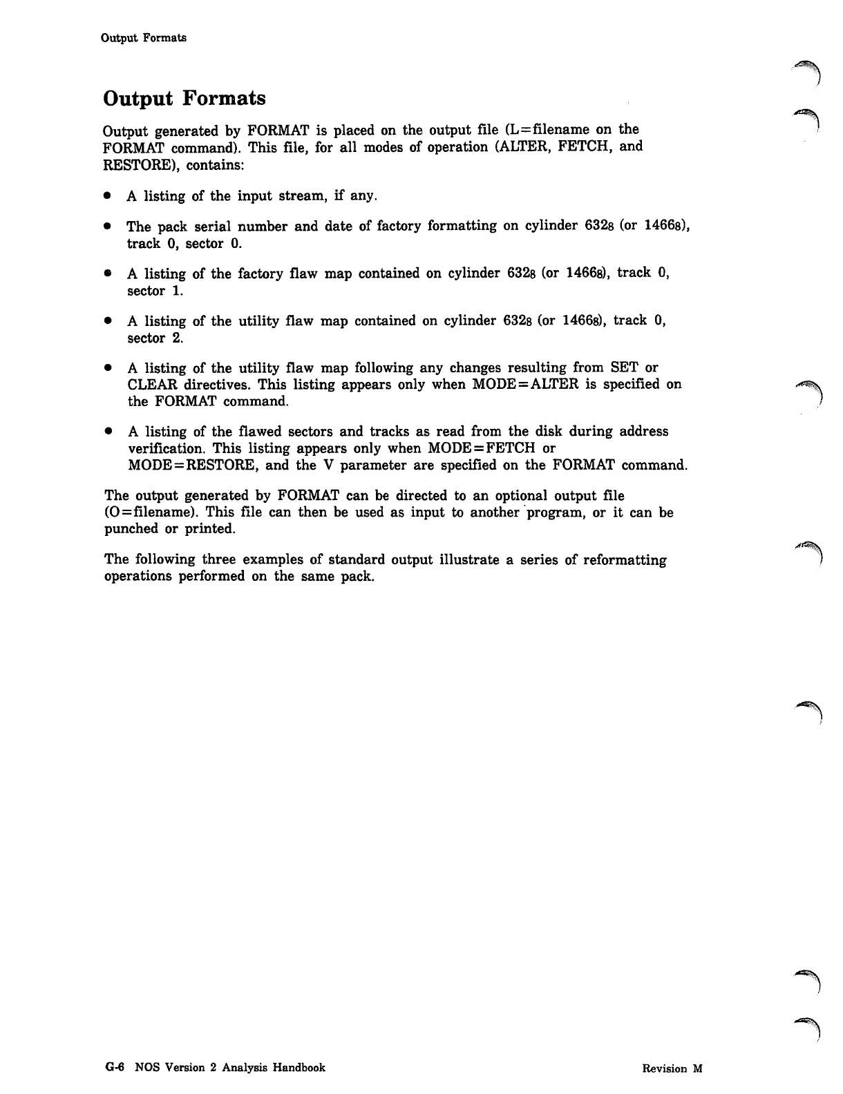
Output Formats
Output Formats
Output generated by FORMAT is placed on the output file (L=filename on the
FORMAT command). This file, for all modes of operation (ALTER, FETCH, and
RESTORE), contains:
• A listing of the input stream, if any.
• The pack serial number and date of factory formatting on cylinder 632s (or 1466s),
track 0, sector 0.
• A listing of the factory flaw map contained on cylinder 6328 (or 1466s), track 0,
sector 1.
• A listing of the utility flaw map contained on cylinder 632s (or 1466s), track 0,
sector 2.
• A listing of the utility flaw map following any changes resulting from SET or
CLEAR directives. This listing appears only when MODE=ALTER is specified on
the FORMAT command.
• A listing of the flawed sectors and tracks as read from the disk during address
verification. This listing appears only when MODE = FETCH or
MODE=RESTORE, and the V parameter are specified on the FORMAT command.
The output generated by FORMAT can be directed to an optional output file
(0=filename). This file can then be used as input to another program, or it can be
punched or printed.
The following three examples of standard output illustrate a series of reformatting
operations performed on the same pack.
-=*%
G-6 NOS Version 2 Analysis Handbook Revision M
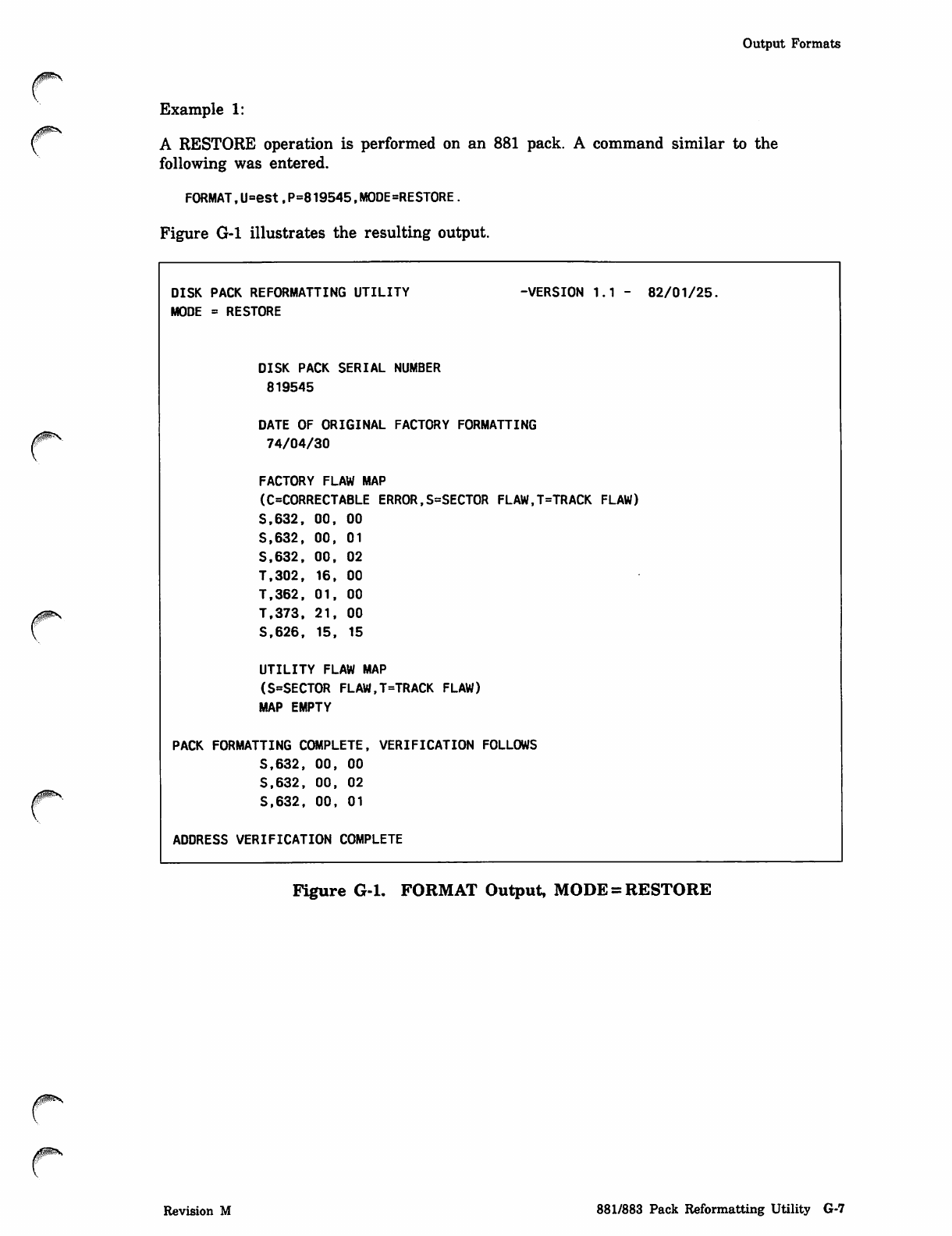
Output Formats
yjpP^V
Example 1:
A RESTORE operation is performed on an 881 pack. A command similar to the
following was entered.
FORMAT,U=est,P=819545,M0DE=REST0RE.
Figure G-l illustrates the resulting output.
DISK PACK REFORMATTING UTILITY
MODE = RESTORE
-VERSION 1.1 - 82/01/25.
DISK PACK SERIAL NUMBER
819545
DATE OF ORIGINAL FACTORY FORMATTING
74/04/30
FACTORY FLAW MAP
(C=CORRECTABLE ERROR,S=SECT0R FLAW,T=TRACK FLAW)
S.632, 00, 00
S.632, 00, 01
S.632, 00, 02
T.302, 16, 00
T.362, 01, 00
T.373, 21, 00
S.626, 15, 15
UTILITY FLAW MAP
(S=SECTOR FLAW,T=TRACK FLAW)
MAP EMPTY
PACK FORMATTING COMPLETE, VERIFICATION FOLLOWS
S.632, 00, 00
S.632, 00, 02
S.632, 00, 01
ADDRESS VERIFICATION COMPLETE
Figure G-l. FORMAT Output, MODE = RESTORE
c
Revision M 881/883 Pack Reformatting Utility G-7
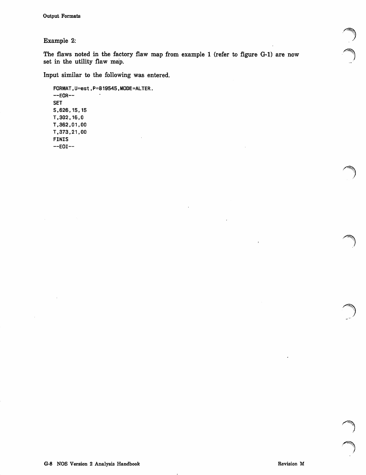
Output Formats
Example 2:
A^ms
The flaws noted in the factory flaw map from example 1 (refer to figure G-l) are now j
set in the utility flaw map.
Input similar to the following was entered.
FORMAT,U=est,P=819545.MODE=ALTER.
__ EOR—
SET
S,626,15,15
T,302 ,16,0
T,362,01,00
Tf373,21,00
FINIS
—EOI—
y^\
y^S\
G-8 NOS Version 2 Analysis Handbook Revision M
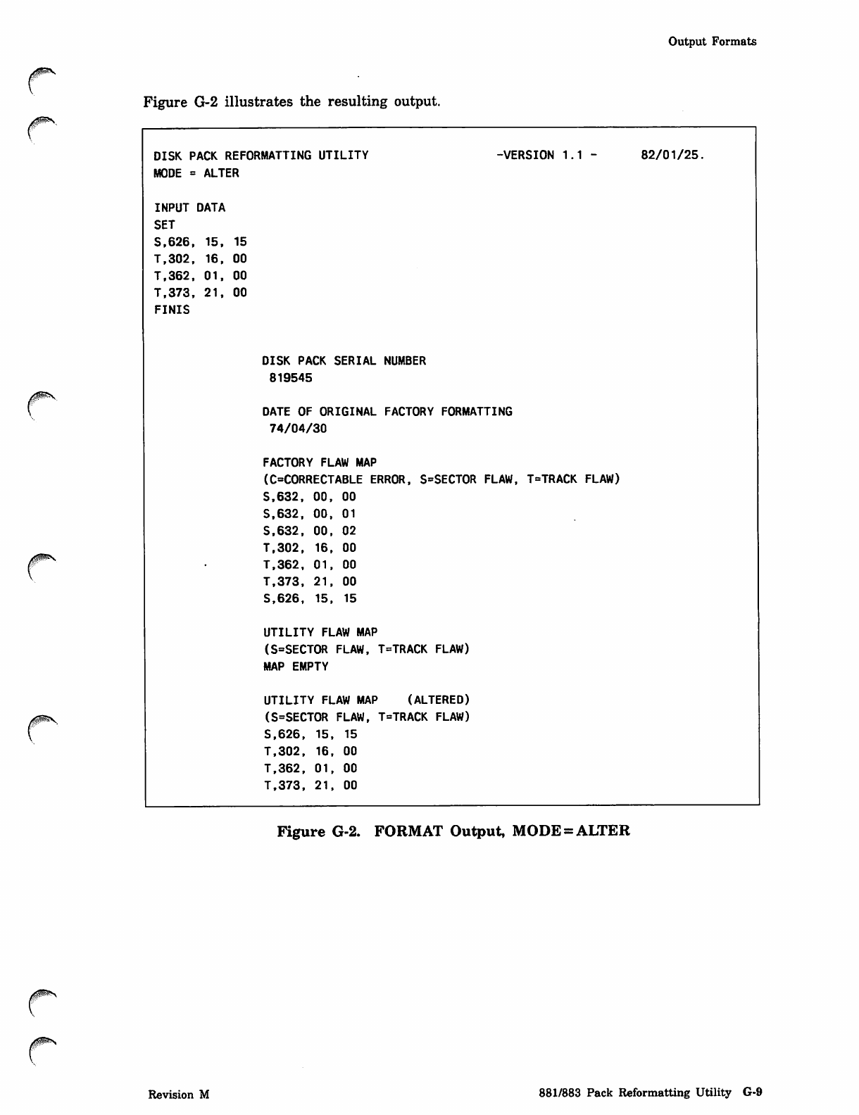
Output Formats
rFigure G-2 illustrates the resulting output.
0ms
DISK PACK REFORMATTING UTILITY
MODE = ALTER
-VERSION 1.1 - 82/01/25.
INPUT DATA
SET
S.626, 15, 15
T.302, 16, 00
T.362, 01, 00
T.373, 21, 00
FINIS
DISK PACK SERIAL NUMBER
819545
DATE OF ORIGINAL FACTORY FORMATTING
74/04/30
FACTORY FLAW MAP
(C=CORRECTABLE ERROR, S=SECTOR FLAW, T=TRACK FLAW)
S.632, 00, 00
S.632, 00, 01
S.632, 00, 02
T.302, 16, 00
T.362, 01, 00
T.373, 21, 00
S.626, 15. 15
UTILITY FLAW MAP
(S=SECTOR FLAW, T=TRACK FLAW)
MAP EMPTY
UTILITY FLAW MAP (ALTERED)
(S=SECTOR FLAW, T=TRACK FLAW)
S.626, 15. 15
T.302, 16, 00
T.362, 01, 00
T.373, 21, 00
Figure G-2. FORMAT Output, MODE = ALTER
Revision M 881/883 Pack Reformatting Utility G-9
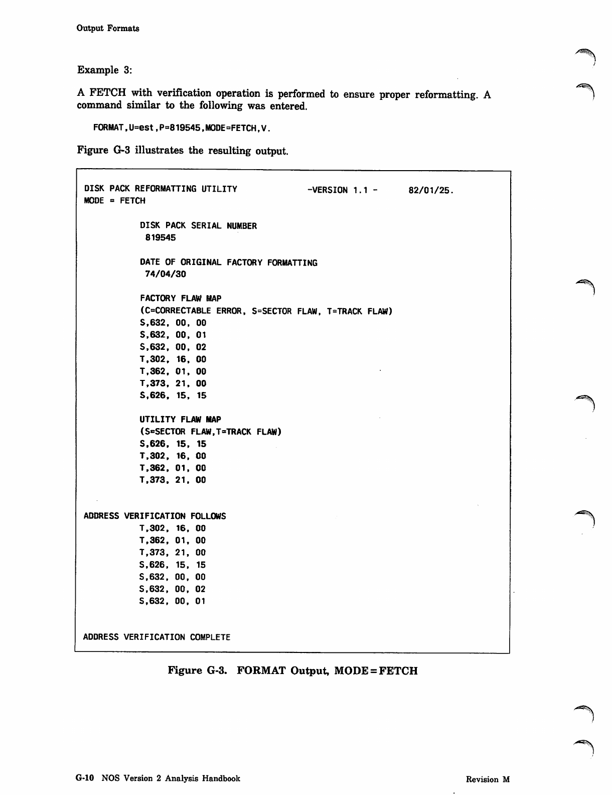
Output Formats
Example 3:
A FETCH with verification operation is performed to ensure proper reformatting. A
command similar to the following was entered.
FORMAT,U=est,P=819545,MODE=FETCH,V.
Figure G-3 illustrates the resulting output.
-VERSION 1.1 -
DISK PACK REFORMATTING UTILITY
MODE = FETCH
DISK PACK SERIAL NUMBER
819545
DATE OF ORIGINAL FACTORY FORMATTING
74/04/30
FACTORY FLAW MAP
(C=CORRECTABLE ERROR, S=SECT0R FLAW, T=TRACK FLAW)
S.632, 00. 00
S.632. 00, 01
S.632, 00. 02
T.302, 16. 00
T.362. 01, 00
T.373, 21. 00
S.626. 15. 15
UTILITY FLAW MAP
(S^SECTOR FLAW,T=TRACK FLAW)
S.626, 15, 15
T.302. 16, 00
T.362. 01. 00
T.373. 21, 00
ADDRESS VERIFICATION FOLLOWS
T.302. 16, 00
T.362, 01. 00
T.373, 21, 00
S.626, 15, 15
S.632. 00. 00
S.632. 00. 02
S.632. 00. 01
ADDRESS VERIFICATION COMPLETE
82/01/25.
'-5*\
Figure G-3. FORMAT Output, MODE = FETCH
G-10 NOS Version 2 Analysis Handbook Revision M
j0mS
Accessing Disk Devices
Accessing Disk Devices
Special procedures must be used to access the 844 drive used in the reformatting
utility. Since certain FORMAT operations (ALTER and RESTORE) can change
addresses on the pack, user access to the pack must be restricted.
FORMAT can operate on the pack as follows.
• A read operation (FETCH) obtains formatting information from the pack. The
integrity of the pack is maintained.
• Read and write operations (ALTER and RESTORE) can set and clear flaws, and
addresses can be rewritten. Users cannot place permanent files on the pack when
these operations occur. The integrity of the data on the pack is lost, so a full
initialization of the pack must occur before system usage occurs.
Access for Read Operations
Accessing the pack for read operations requires that you specify the U parameter on
the FORMAT command with the correct EST ordinal of the device containing the pack.
In this case, the device must be a single-spindle device unless you also specify the G
parameter. You must also specify the P parameter with the correct pack serial number.
In addition, FORMAT must be called from one of the following.
• A system origin job (from the console).
• A system privileged job (in this case, engineering mode must have been selected on
the system console).
Revision M 881/883 Pack Reformatting Utility G-ll
Access for Read and Write Operations
Access for Read and Write Operations
In addition to the information specified for read only operations, the following
additional steps must be taken to access a device when write operations (ALTER and
RESTORE) are to be performed.
1. The pack to be accessed should be mounted on a removable disk device.
2. One of the following conditions is required.
• The device should not be a shared device. (Refer to section 13, Multimainframe
Operations.)
• If the device is shared, a global unload should be set.
3. The device must be declared logically off. Use the OFF DSD command or the OFF
parameter in the EQPDECK EQ entry.
4. The disk status display (E,M) must show that the device is not in use.
5. One of the following conditions is required.
• The disk status display (E,M) must show that the device is unavailable for
permanent file access.
• The following conditions are required.
- The full initialize status and the format pending status must be set. Use
the DSD command, INITIALIZE,FP,est.
- The direct access file user count should be equal to zero. The family status
display (E,F) gives this information.
If all the necessary conditions are satisfied, FORMAT is able to access the pack for
reformatting purposes. FORMAT repeatedly checks to ensure that these conditions are
satisfied throughout the FORMAT operation.
At the end of the FORMAT process the disk must be initialized (INITIALIZE ,AL,est)
to copy the flaw information to the TRT and label. Otherwise, the flaw map changes
will have no effect on NOS until the next time the disk is recovered. At that time, '*s%
unreserved tracks marked as flaws in the flaw map will be flawed in the appropriate
NOS tables.
G-12 NOS Version 2 Analysis Handbook Revision M
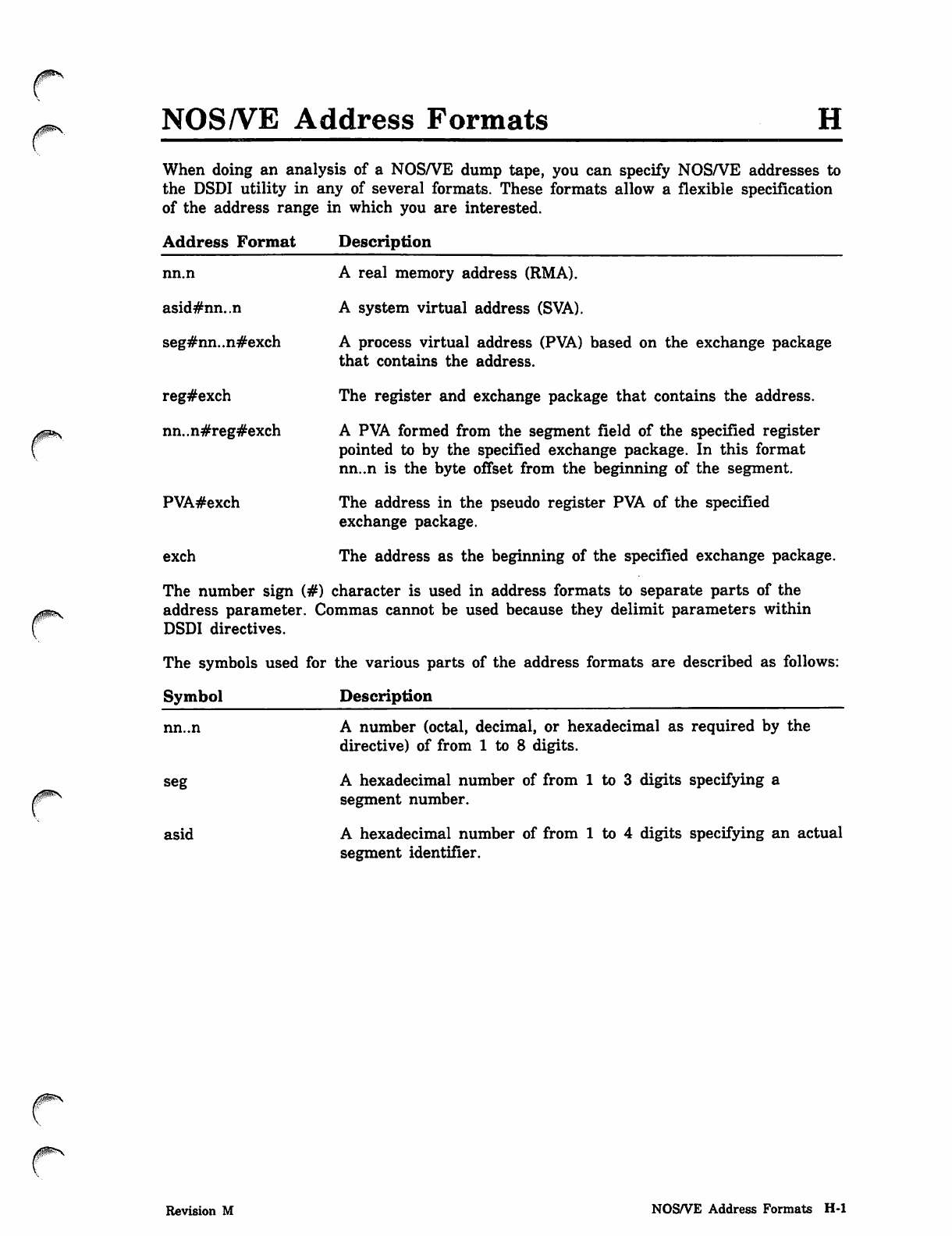
NOS/VE Address Formats
When doing an analysis of a NOS/VE dump tape, you can specify NOS/VE addresses to
the DSDI utility in any of several formats. These formats allow a flexible specification
of the address range in which you are interested.
Address Format Description
nn.n
asid#nn..n
seg#nn..n#exch
reg#exch
nn..n#reg#exch
PVA#exch
exch
A real memory address (RMA).
A system virtual address (SVA).
A process virtual address (PVA) based on the exchange package
that contains the address.
The register and exchange package that contains the address.
A PVA formed from the segment field of the specified register
pointed to by the specified exchange package. In this format
nn..n is the byte offset from the beginning of the segment.
The address in the pseudo register PVA of the specified
exchange package.
The address as the beginning of the specified exchange package.
The number sign (#) character is used in address formats to separate parts of the
address parameter. Commas cannot be used because they delimit parameters within
DSDI directives.
The symbols used for the various parts of the address formats are described as follows:
Symbol Description
nn..n
seg
asid
A number (octal, decimal, or hexadecimal as required by the
directive) of from 1 to 8 digits.
A hexadecimal number of from 1 to 3 digits specifying a
segment number.
A hexadecimal number of from 1 to 4 digits specifying an actual
segment identifier.
Revision M NOS/VE Address Formats H-l
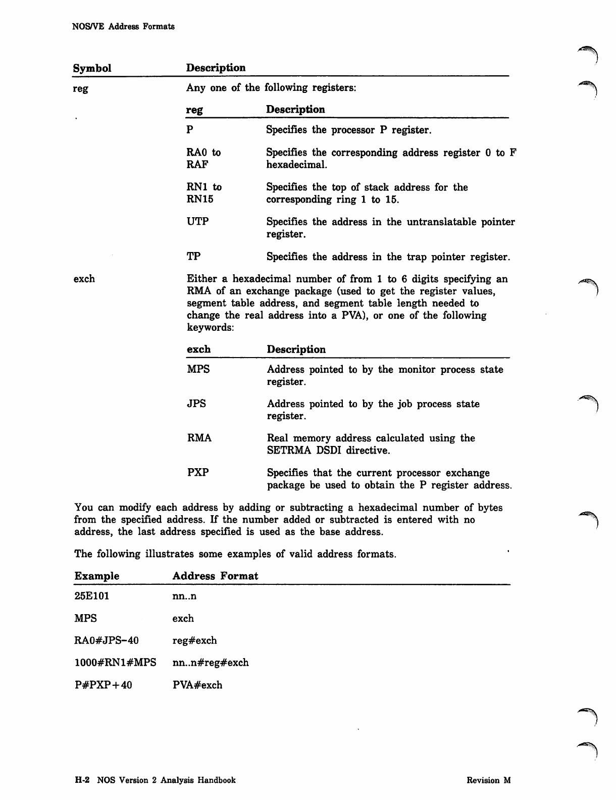
NOS/VE Address Formats
Symbol Description
reg Any one of the following registers:
reg Description
exch
P Specifies the processor P register.
RAO to Specifies the corresponding address register 0 to F
RAF hexadecimal.
RNI to Specifies the top of stack address for the
RN15 corresponding ring 1 to 15.
UTP Specifies the address in the untranslatable pointer
register.
TP Specifies the address in the trap pointer register.
Either a hexadecimal number of from 1 to 6 digits specifying an
RMA of an exchange package (used to get the register values,
segment table address, and segment table length needed to
change the real address into a PVA), or one of the following
keywords:
exch Description
MPS
JPS
RMA
PXP
Address pointed to by the monitor process state
register.
Address pointed to by the job process state
register.
Real memory address calculated using the
SETRMA DSDI directive.
Specifies that the current processor exchange
package be used to obtain the P register address.
You can modify each address by adding or subtracting a hexadecimal number of bytes
from the specified address. If the number added or subtracted is entered with no
address, the last address specified is used as the base address.
The following illustrates some examples of valid address formats.
Example Address Format
25E101 nn..n
MPS exch
RA0#JPS-40 reg#exch
1000#RN1#MPS nn..n#reg#exch
P#PXP+40 PVA#exch
.■^B^\
.--SSS
H-2 NOS Version 2 Analysis Handbook Revision M
Management Of Storage Media Defects I
This appendix describes the process of detecting failing devices that are suspected of
having storage media defects and the process of dealing with known storage media
defects.
Detecting Failing Devices
This aspect of storage media management is the process of detecting failing mass
storage devices and making informed decisions regarding the proper course of action.
The action may be to place a failing disk in idle mode, change its threshold values, or
set its device state to OFF or DOWN. These actions are discussed in the following
paragraphs.
When a mass storage device or channel begins to fail, the system directs new file
assignments away from the device and inhibits access to files on the device that are
being used by executing jobs.
The operator is alerted to the device failure through the A,OPERATOR display. Also
the E,E and E,H displays provide an overview of the mass storage devices that have
abnormal conditions present. The E,E display shows that a device error has occurred
on a particular device and the current state of that device. The E,H display shows the
current mass storage threshold values and the current count associated with each
threshold value. Refer to the NOS Version 2 Operations Handbook for additional
information about the E,E and E,H displays.
You can use the IDLE command in conjunction with the THRESHOLD command to
maintain some degree of flexibility in deciding when to repair the failing device. For
more information, refer to the IDLE and THRESHOLD commands in section 5, DSD
Commands.
NOTE
The decision to continue using a failing device should be made under the advisement of
a customer engineer. If there is a chance of data corruption due to the nature of the
failure, it may be best to leave the device OFF or DOWN until it can be repaired.
Revision M Management Of Storage Media Defects 1-1
Disk Idle Mode
Disk Idle Mode
A^S
When a disk is in idle mode, the system temporarily eliminates access to the device /
when it starts to fail. Nonsubsystem jobs accessing the device will be rolled out so that
the rest of the system and jobs not accessing the device can continue running. A
verification algorithm will be used to. attempt to isolate the problem to a particular
part of the hardware (media, drive, controller, or channel). If the cause of the problem
can be isolated to a failing channel or drive, then the system will attempt to DOWN
that particular hardware resource.
Mass Storage Thresholds
The initial threshold values for a mass storage device are determined by THRESHOLD
EQPDECK entries in the deadstart file. You can use the DSD THRESHOLD command
to change the following threshold values for any mass storage device:
• Verification failure threshold
j^m\
• Restricted activity threshold j
• Low space threshold
• Recovered error threshold
• Unrecovered error threshold
These threshold values are described under the DSD THRESHOLD command in
section 5.
When the space available on a mass storage device falls below the low space threshold,
the following message appears on the A,OPERATOR display:
LOW SPACE ON MASS STORAGE DEVICE.
1-2 NOS Version 2 Analysis Handbook Revision M
yams
Dealing With Known Media Defects
Dealing With Known Media Defects
This aspect of storage media management is the process of dealing with known media
defects on mass storage devices. This process includes keeping an accurate record of all
known defects and preventing the system from using defective areas. You should follow
these general steps when you or the system encounter a media defect:
1. Record the media defect in a logbook.
2. Use the FLAW utility to reserve (flaw) the defective area and prevent the system
from using that space.
3. Modify or create an APRDECK for the device containing the defect to include a
command to flaw the defective area.
4. Modify the EQPDECK entry for the device to include a reference to the APRDECK
entry.
This appendix describes general procedures for storage media management and the
software tools you will need to perform these procedures. Later in this appendix an
example shows the specific steps you should perform given a defined media defect
problem.
Keeping An Accurate Record of Media Defects
Your site should maintain a logbook that documents all of the known mass storage
media defects. This logbook should be kept by the system console so that an operator
can record any media defect messages displayed. The information can then be used to
reserve defective areas and thus prevent the system from using them.
Preventing The System From Using Flawed Disk Space
NOS allocates space on a mass storage device in units of logical tracks. For example,
when you write a file to disk, NOS assigns a logical track to the file and then writes
the file information to that logical track. The logical track remains assigned to the file
until you release the file. That is, as long as the logical track is assigned to your file,
it cannot be assigned to another file.
To prevent NOS from assigning a defective logical track to a file, you must reserve the
track. This is called flawing a track. However, you cannot flaw a track while it is in
use; that is, if the logical track with the defect is currently assigned to a file, you
cannot flaw the track until the file is released.
If a media defect is encountered on a logical track assigned to a type of file that will
not be released (such as, the system file, dayfiles, permanent file catalogs, and system
checkpoint files) you will have to perform special procedures to explicitly move these
files and then flaw the track. For example, you may need to dump and reload
permanent files, reinitialize a disk, or deadstart the system. For a discussion of dealing
with media defects encountered on areas assigned to these files, refer to Releasing
Special Files and Reinitializing a Device later in this appendix.
Revision M Management Of Storage Media Defects 1-3
ylRK
Media Management Tools
Media Management Tools
| You can use the following software tools to help with storage media management:
I • Error log messages for 887, 895, and 9853 disks
| • FLAW utility
| • APRDECK entries
| • EQPDECK entries
I • FORMAT utility for 881/883 disk packs
| Error Log Messages for 887, 895, and 9853 Disks
I NOS automatically detects the presence of a media defect on an 887, 895, or 9853 disk.
| NOS automatically flaws the logical track that contains the media defect when the file
| containing the logical track is released.
I When NOS encounters a media defect on an 887, 895, or 9853 disk, it issues a SEE
| A,ERROR LOG message to the operator. The operator should then use the A,ERROR
| LOG command to view the error log screen. The following message describes the media
| defect encountered:
dtest.TKnnnn,MEDIA DEFECT ENCOUNTERED
where dt is the device type, est is the EST ordinal of the device, and nnnn is the
number of the logical track containing the media defect.
The operator should copy this message to a logbook for future use. This message
indicates that NOS has detected a media defect; it does not indicate that the defective
area has been automatically flawed. When the file assigned to the logical track
containing the defect is released, NOS will then automatically flaw the track.
However, because media defects are rare (they should occur only once per device every
two years), NOS stores only one media defect; the last defect encountered. Thus, your
operator should always log the media defects encountered so that the information will
not be lost if multiple defects occur. ***%.
When NOS automatically flaws a logical track, it again issues a SEE A,ERROR LOG
message to the operator and displays this message on the error log screen:
dtest,TKnnnn,MEDIA DEFECT FLAWED
The operator should copy this message to a logbook for future use.
FLAW Utility
If a media defect occurs during normal system operation, use the FLAW utility to
reserve (flaw) the defective track. (You can also use the FLAW utility to clear any
flaws previously set.) To flaw a defective logical track, you must know the EST ordinal
of the device containing the defect and the logical track number of the defect. For
more information, refer to FLAW K Display in section 8, K-Display Utilities.
~}
1-4 NOS Version 2 Analysis Handbook Revision M
/fJRX
APRDECK Entries
APRDECK Entries
In addition to using the FLAW utility to flaw a defective area of mass storage, you
should also modify the APRDECK (auxiliary mass storage parameter deck) for the
device containing the defect.
An APRDECK is a text record on the deadstart file that is used when the device is
initialized. APRDECK entries identify areas of mass storage that are unusable (flawed)
and prevent the system from accessing them. The system uses the information in the
APRDECK entries to build the track reservation table (TRT) that resides in central
memory resident (CMR) and also in the mass storage device label for each device.
By making APRDECK entries, you cause the system to flaw the media defects without
your intervention during the next deadstart initialization of the device. For more
information, refer to APRDECK in section 3, Deadstart Decks.
EQPDECK Entries
An EQPDECK (equipment deck) is a text record on the deadstart file that declares all
the devices that comprise your computer system. Each device is defined to the system
with an EQPDECK entry. An optional parameter on the EQPDECK entry declares an
APRDECK for the device. When you create an APRDECK entry for a device, modify
the EQPDECK entry for the device to include the reference to the APRDECK entry.
For more information, refer to EQPDECK in section 3, Deadstart Decks.
FORMAT Utility for 881/883 Disk Packs
When you use the FLAW utility or an APRDECK entry to flaw an area of an 881 or
883 disk pack, this flawing is only logical. That is, the flaw information is kept in the
TRT and is discarded on subsequent deadstart initializations of the device. This
information is also lost during online initializations if it was not possible to recover the
equipment.
For 881 and 883 disk packs, which contain factory-recorded utility maps, you have the
option of storing flaw information on the utility map on the disk. To modify or add
information to the utility map, use the FORMAT utility. For more information, refer to
appendix G.
Revision M Management Of Storage Media Defects 1-5
Media Defect Example
Media Defect Example
Suppose a job encounters a media defect on a local file. The file is located on an 895
disk device with EST ordinal 15 and the bad track is 5010. Use the following
procedure to record the media defect and flaw the defective area.
1. When the system displays the message SEE *A,OPERATOR* use the A.OPERATOR
command to view the operator screen. This message is displayed:
13 SEE A,ERROR LOG.
2. To view the error log, enter this command:
A,ERROR LOG.
The following message is displayed on the error log screen:
EQ015.TK5010.MEDIA DEFECT ENCOUNTERED.
3. Record the information in the media defect logbook.
4. Enter this command to tell the system you are taking care of the problem:
LOG,13.
5. When the job using the local file releases the file, the following message is
displayed on the error log screen:
EQ015.TK5010.MEDIA DEFECT FLAWED.
6. Record the information in the media defect logbook.
7. Suppose there is no APRDECK for the device with EST ordinal 15. Add the
AP=nn parameter to the EQPDECK entry for device 15. Here is an example of
what the EQPDECK entry should look like:
EQO15=type,ST=0N,CH=ch,AP»00.
This entry assigns the first APRDECK to device 15.
8. Create the APRDECK for device 15:
APRD00.
SLF=5010.
9. Use the LIBEDIT command to place the APRDECK entry and the updated
EQPDECK entry on the deadstart file. (Remember that the number of the
APRDECK record is determined by its position in relation to the APRINST record
and not by the number on the record name; it is a good idea to name the records
according to their position.)
A-m*
1-6 NOS Version 2 Analysis Handbook Revision M
Releasing Special Files
Releasing Special Files
Because a media defect cannot be flawed automatically by the system until the file
assigned to the defective track is released, you may have to release certain file types:
File Description
Direct access file When a flaw is detected on a track assigned to a direct access
file, purge the file so that the system can perform automatic
track flawing for the bad track.
Dayfile Job dayfiles are released at job termination; system dayfiles are
released when they are initialized or if you perform a DFTERM
and then purge the files created by DFTERM.
System file The system file is released at deadstart. Thus, at deadstart a
defective track assigned to the system file will be flawed
automatically.
Reinitializing A Device
Some track chains are not released unless the device is reinitialized:
• Indirect access file chain.
• Disk deadstart file.
• Catalog track chain.
If a storage media defect is encountered in one of these files, perform the following
steps:
1. Create or update an APRDECK for the device.
2. Modify the EQPDECK entry for the device to include the APRDECK reference.
3. Dump the files on the device to tape.
4. Reinitialize the device.
5. Reload the files to the device.
Revision M Management Of Storage Media Defects 1-7

y^mitt
Display Disk File (DDF) Utility J
The Display Disk File (DDF) utility provides the capability to read, display, change,
and print the contents of physical disk sectors. It is intended to be used by analysts as
an aid when working on system problems that involve data stored on mass storage
devices.
CAUTION
Changing disk table contents should be done carefully and only by analysts who
understand the effects of the changes. Unless extreme care is exercised, use of DDF
can lead to system hangs or loss of permanent files.
Bringing Up DDF
The DSD display for the DDF utility is brought up on the system console by entering
the following command:
x.DDF.
NOTE
Since DDF allows access to all disk space without regard for security access levels and
categories, use of DDF in a secured system requires that the system be in
SECURITY-UNLOCK state (refer to Secured System Control Commands in section 5,
DSD Commands).
Revision M Display Disk File (DDF) Utility J-l
DDF Display Left Screen
DDF Display Left Screen
The left screen displays the following disk and control point information:
Disk EST ordinal and equipment type.
Current disk track and sector address.
Central memory address and byte number of the TRT link byte for the current
track. The link byte is intensified if it is not consistent with the sector linkage
bytes.
TRT reservation, interlock, and preserved file status for the current track.
Family name, pack name, control point number, and JSN of the associated job.
Track numbers for the first track of the permit chain and the first track of the
indirect access file data chain for the specified family/pack.
First and second control point messages, if issued. The second control point message )
is usually a disk error and is intensified.
Contents of DDF scratch areas, labeled A through F (refer to the DDF STORE
command).
The recovery track pointer and track recovery word, when pack recovery is in
progress.
Various status and errors may be displayed at the bottom of the screen.
J-2 NOS Version 2 Analysis Handbook Revision M
DDF Display Right Screen
DDF Display Right Screen
The right screen displays the contents of the specified disk sector. The byte numbers
displayed in parenthesis after the central memory address are the actual byte numbers
for the physical disk sector. The byte numbers are used in the memory changing
commands.
You can change the right screen format with the right blank key on the CC545 console
or the tab key on the CC634B console.
The following right screen displays are available:
• Five Bytes Per Line. The contents of the sector are displayed in 5 bytes per line.
The CC545 console displays one half sector per page and uses the / to toggle
between the first and second half of the sector. The CC598B and CC634B consoles
display one quarter of a sector per page and uses the / to increment the addresses.
• Ten Bytes Per Line. The contents of the sector are displayed in 108 bytes per line
with byte numbers. The CC545 console displays the entire sector on one page. The
CC598B and CC634B consoles display one half sector per page and uses the / to
toggle between the first and second half of the sector.
• Text Mode. The contents of the sector are displayed in text mode. The CC545
console displays the entire sector on one page. The CC598B and CC634B consoles
display one half sector per page and uses the / to toggle between the first and
second half of the sector.
• Interpreted mode. The data is formatted in one of three ways depending on the
linkage bytes:
- System Sector. The file name table (FNT) word and file status table (FST) word
of the file are displayed along with the date and time when the sector was last
updated. If the file type is PMFT, the copy of the permanent file catalog entry
(PFC) contained in the system sector is also displayed.
- PFC Entry or Data Sector. The contents of one permanent file catalog entry (20s
words) are displayed. Some fields such as dates are decoded. The / is used to
advance to the next PFC entry in the sector.
- End of Information Sector. This display shows a short format of the system
sector display.
• Legal Commands. This display shows a list of the DDF commands.
Revision M Display Disk File (DDF) Utility J-3
Keyboard Input
/*^\
Keyboard Input
You can use the following keys to interact with the DDF display.
Key Action Initiated
+ Read the next sector. If positioned at EOI or the end of the
track, the current sector is reread.
Read the previous sector. If positioned at the beginning of the
track, the current sector is reread.
Advance to the track specified in the control bytes and set the
sector to 0. If the control bytes do not contain a track link,
the current sector is reread.
, Advance to the next track in the TRT chain. The sector
number is not changed. If currently at the last track in the
chain, the current sector is reread.
= Read the next sector, continuing past EOI. If positioned at the
end of an EOI track, the current sector is reread.
CR or NEXT
Space bar
8
9
Right blank,
or Tab
BKSP, <—
Back Space
or
Left blank, kf
Esc
or
Initiate processing of an entered command. This key also sets
REPEAT ENTRY if a complete command has not yet been
entered.
Read the current sector into the buffer. The current sector is
the sector to which the current EST ordinal, track, and sector
values point.
Toggle between DSD and DDF.
Increment the track number by one and read the sector.
Decrement the track number by one and read the sector.
Change the right screen displays on the CC545 console. This
function is done by the Tab key on the CC598B console and
the i*\ (tab) key on the CC634B console.
Toggle or increment the sector displays on the right screen.
Delete the previous character typed on the CC545 console.
This function is done by the Back Space key on the CC598B
console and by the back arrow < (backspace) key on the
CC634B console.
Delete the current line being entered on the CC545 console.
This function is done by the Esc key on the CC598B console
and thekt (back tab) key on the CC634B console.
J-4 NOS Version 2 Analysis Handbook Revision M
Console Messages
r
Console Messages
The following messages may appear at the control point.
Message Description
WAITING FOR MEMORY
READING EQxxx TPxxxx CTxxxx
DDF is waiting for central memory to store
the display and command processors.
This message shows the status of checkout
during a pack recovery operation.
The following messages may appear above the command line at the bottom of the left
screen.
Message Description
FORMAT ERROR.
INCORRECT ENTRY.
INCORRECT EQUIPMENT.
INCORRECT PARAMETER.
REPEAT ENTRY.
SYSTEM BUSY.
BYTE xxxx.
LENGTH = nnnn.
Some commands read several sectors. If
one of these commands, processing stops
A format error has been detected during
translation of the entry.
The command is not valid.
EST is not mass storage, nor is it a null
equipment.
The parameter in the entry is invalid or too
long.
The entry will not be cleared after execution.
DDF is waiting for the system to process a
request.
The data specified is in byte number xxxx.
The SKIPEI command has skipped nnnn octal
sectors.
a disk error is encountered while processing
and an error code appears on the left screen.
Revision M Display Disk File (DDF) Utility J-5
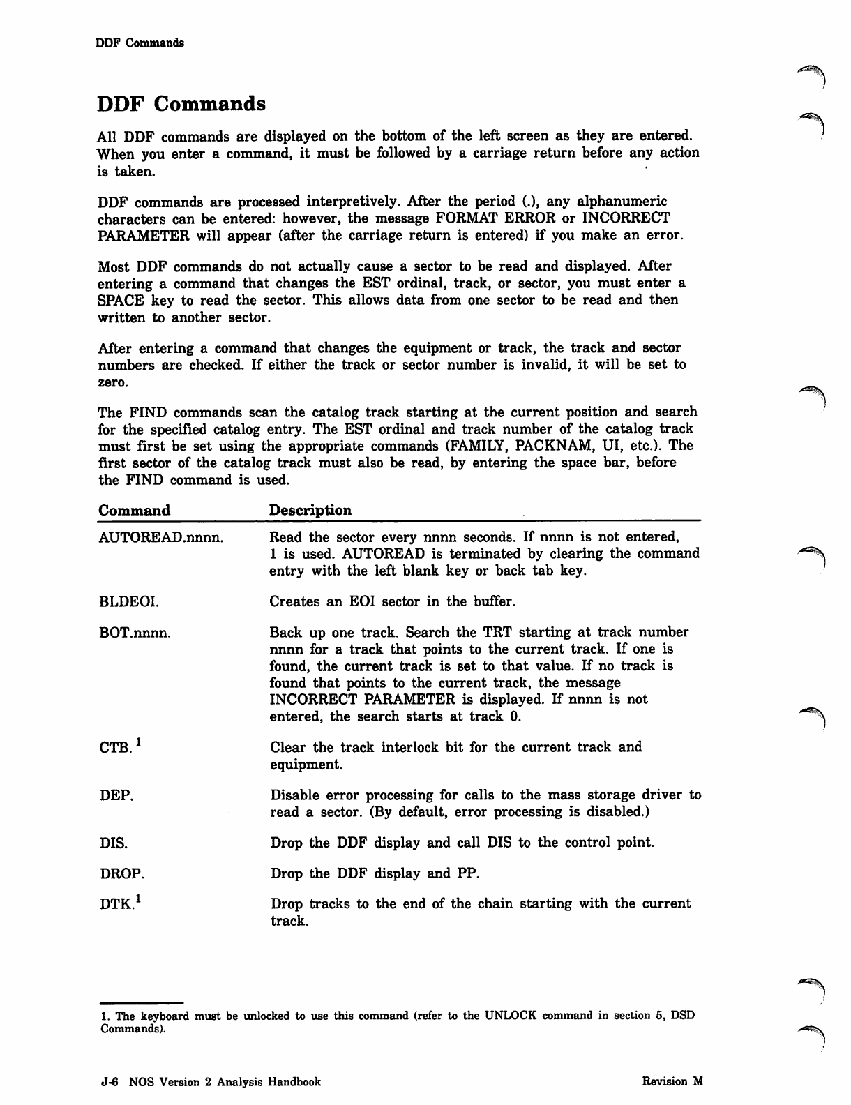
DDF Commands
DDF Commands
All DDF commands are displayed on the bottom of the left screen as they are entered.
When you enter a command, it must be followed by a carriage return before any action
is taken.
DDF commands are processed interpretively. After the period (.), any alphanumeric
characters can be entered: however, the message FORMAT ERROR or INCORRECT
PARAMETER will appear (after the carriage return is entered) if you make an error.
Most DDF commands do not actually cause a sector to be read and displayed. After
entering a command that changes the EST ordinal, track, or sector, you must enter a
SPACE key to read the sector. This allows data from one sector to be read and then
written to another sector.
After entering a command that changes the equipment or track, the track and sector
numbers are checked. If either the track or sector number is invalid, it will be set to
zero.
The FIND commands scan the catalog track starting at the current position and search
for the specified catalog entry. The EST ordinal and track number of the catalog track
must first be set using the appropriate commands (FAMILY, PACKNAM, UI, etc.). The
first sector of the catalog track must also be read, by entering the space bar, before
the FIND command is used.
Command Description
AUTOREAD.nnnn.
BLDEOI.
BOT.nnnn.
CTB.1
DEP.
DIS.
DROP.
DTK
Read the sector every nnnn seconds. If nnnn is not entered,
1 is used. AUTOREAD is terminated by clearing the command
entry with the left blank key or back tab key.
Creates an EOI sector in the buffer.
Back up one track. Search the TRT starting at track number
nnnn for a track that points to the current track. If one is
found, the current track is set to that value. If no track is
found that points to the current track, the message
INCORRECT PARAMETER is displayed. If nnnn is not
entered, the search starts at track 0.
Clear the track interlock bit for the current track and
equipment.
Disable error processing for calls to the mass storage driver to
read a sector. (By default, error processing is disabled.)
Drop the DDF display and call DIS to the control point.
Drop the DDF display and PP.
Drop tracks to the end of the chain starting with the current
track.
/ ^ ^ .
1. The keyboard must be unlocked to use this command (refer to the UNLOCK command in section 5, DSD
Commands).
•*^®S\
J-41 NOS Version 2 Analysis Handbook Revision M
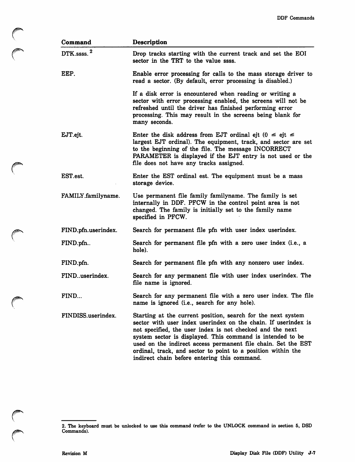
DDF Commands
Command Description
DTK.ssss.2
EEP.
EJT.ejt.
EST.est.
FAMILY.familyname.
FIND.pfn.userindex.
FIND.pfn..
FIND.pfn.
FIND..userindex.
FIND...
FINDISS.userindex.
Drop tracks starting with the current track and set the EOI
sector in the TRT to the value ssss.
Enable error processing for calls to the mass storage driver to
read a sector. (By default, error processing is disabled.)
If a disk error is encountered when reading or writing a
sector with error processing enabled, the screens will not be
refreshed until the driver has finished performing error
processing. This may result in the screens being blank for
many seconds.
Enter the disk address from EJT ordinal ejt (0 ^ ejt ^
largest EJT ordinal). The equipment, track, and sector are set
to the beginning of the file. The message INCORRECT
PARAMETER is displayed if the EJT entry is not used or the
file does not have any tracks assigned.
Enter the EST ordinal est. The equipment must be a mass
storage device.
Use permanent file family familyname. The family is set
internally in DDF. PFCW in the control point area is not
changed. The family is initially set to the family name
specified in PFCW.
Search for permanent file pfn with user index userindex.
Search for permanent file pfn with a zero user index (i.e., a
hole).
Search for permanent file pfn with any nonzero user index.
Search for any permanent file with user index userindex. The
file name is ignored.
Search for any permanent file with a zero user index. The file
name is ignored (i.e., search for any hole).
Starting at the current position, search for the next system
sector with user index userindex on the chain. If userindex is
not specified, the user index is not checked and the next
system sector is displayed. This command is intended to be
used on the indirect access permanent file chain. Set the EST
ordinal, track, and sector to point to a position within the
indirect chain before entering this command.
2. The keyboard must be unlocked to use this command (refer to the UNLOCK command in section 5, DSD
Commands).
Revision M Display Disk File (DDF) Utility J-7
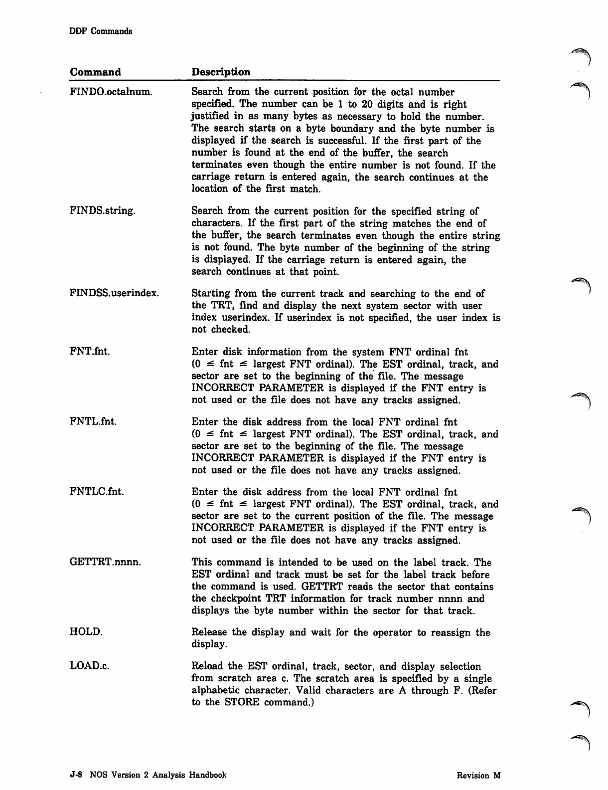
DDF Commands
Command
FINDO.octalnum.
FINDS.string.
FINDSS.userindex.
FNT.fnt.
FNTL.fnt.
FNTLCfnt.
GETTRT.nnnn.
HOLD.
LOAD.c.
Description
Search from the current position for the octal number
specified. The number can be 1 to 20 digits and is right
justified in as many bytes as necessary to hold the number.
The search starts on a byte boundary and the byte number is
displayed if the search is successful. If the first part of the
number is found at the end of the buffer, the search
terminates even though the entire number is not found. If the
carriage return is entered again, the search continues at the
location of the first match.
Search from the current position for the specified string of
characters. If the first part of the string matches the end of
the buffer, the search terminates even though the entire string
is not found. The byte number of the beginning of the string
is displayed. If the carriage return is entered again, the
search continues at that point.
Starting from the current track and searching to the end of
the TRT, find and display the next system sector with user
index userindex. If userindex is not specified, the user index is
not checked.
Enter disk information from the system FNT ordinal fnt
(0 ^ fnt ^ largest FNT ordinal). The EST ordinal, track, and
sector are set to the beginning of the file. The message
INCORRECT PARAMETER is displayed if the FNT entry is
not used or the file does not have any tracks assigned.
Enter the disk address from the local FNT ordinal fnt
(0 ^ fnt ^ largest FNT ordinal). The EST ordinal, track, and
sector are set to the beginning of the file. The message
INCORRECT PARAMETER is displayed if the FNT entry is
not used or the file does not have any tracks assigned.
Enter the disk address from the local FNT ordinal fnt
(0 ^ fnt ^ largest FNT ordinal). The EST ordinal, track, and
sector are set to the current position of the file. The message
INCORRECT PARAMETER is displayed if the FNT entry is
not used or the file does not have any tracks assigned.
This command is intended to be used on the label track. The
EST ordinal and track must be set for the label track before
the command is used. GETTRT reads the sector that contains
the checkpoint TRT information for track number nnnn and
displays the byte number within the sector for that track.
Release the display and wait for the operator to reassign the
display.
Reload the EST ordinal, track, sector, and display selection
from scratch area c. The scratch area is specified by a single
alphabetic character. Valid characters are A through F. (Refer
to the STORE command.)
J-8 NOS Version 2 Analysis Handbook Revision M
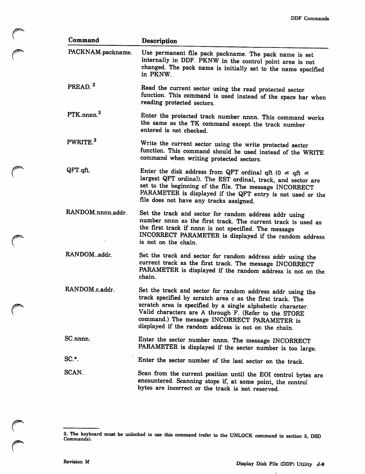
DDF Commands
Command Description
PACKNAM.packname.
PREAD.3
PTK.nnnn.3
PWRITE.3
QFT.qft.
RANDOM.nnnn.addr.
/$Rv
RANDOM..addr.
RANDOM.c.addr.
SC.nnnn.
SC*.
SCAN.
Use permanent file pack packname. The pack name is set
internally in DDF. PKNW in the control point area is not
changed. The pack name is initially set to the name specified
in PKNW.
Read the current sector using the read protected sector
function. This command is used instead of the space bar when
reading protected sectors.
Enter the protected track number nnnn. This command works
the same as the TK command except the track number
entered is not checked.
Write the current sector using the write protected sector
function. This command should be used instead of the WRITE
command when writing protected sectors.
Enter the disk address from QFT ordinal qft (0 ^ qft ^
largest QFT ordinal). The EST ordinal, track, and sector are
set to the beginning of the file. The message INCORRECT
PARAMETER is displayed if the QFT entry is not used or the
file does not have any tracks assigned.
Set the track and sector for random address addr using
number nnnn as the first track. The current track is used as
the first track if nnnn is not specified. The message
INCORRECT PARAMETER is displayed if the random address
is not on the chain.
Set the track and sector for random address addr using the
current track as the first track. The message INCORRECT
PARAMETER is displayed if the random address is not on the
chain.
Set the track and sector for random address addr using the
track specified by scratch area c as the first track. The
scratch area is specified by a single alphabetic character.
Valid characters are A through F. (Refer to the STORE
command.) The message INCORRECT PARAMETER is
displayed if the random address is not on the chain.
Enter the sector number nnnn. The message INCORRECT
PARAMETER is displayed if the sector number is too large.
Enter the sector number of the last sector on the track.
Scan from the current position until the EOI control bytes are
encountered. Scanning stops if, at some point, the control
bytes are incorrect or the track is not reserved.
3. The keyboard must be unlocked to use this command (refer to the UNLOCK command in section 5 DSD
Commands). '
Revision M Display Disk File (DDF) Utility J-9
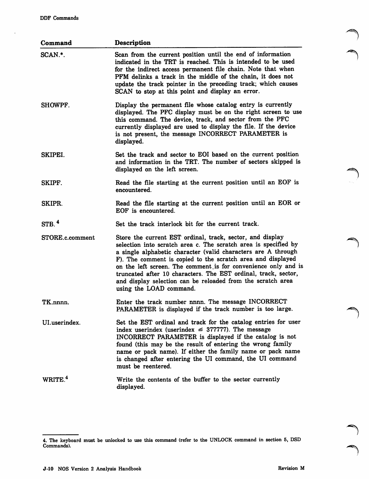
DDF Commands
Command Description
SCAN.
SHOWPF.
SKIPEI.
SKIPF.
SKIPR.
STB.4
STORE.c.comment
TK.nnnn.
Ul.userindex.
WRITE.
Scan from the current position until the end of information
indicated in the TRT is reached. This is intended to be used
for the indirect access permanent file chain. Note that when
PFM delinks a track in the middle of the chain, it does not
update the track pointer in the preceding track; which causes
SCAN to stop at this point and display an error.
Display the permanent file whose catalog entry is currently
displayed. The PFC display must be on the right screen to use
this command. The device, track, and sector from the PFC
currently displayed are used to display the file. If the device
is not present, the message INCORRECT PARAMETER is
displayed.
Set the track and sector to EOI based on the current position
and information in the TRT. The number of sectors skipped is
displayed on the left screen.
Read the file starting at the current position until an EOF is
encountered.
Read the file starting at the current position until an EOR or
EOF is encountered.
Set the track interlock bit for the current track.
Store the current EST ordinal, track, sector, and display
selection into scratch area c. The scratch area is specified by
a single alphabetic character (valid characters are A through
F). The comment is copied to the scratch area and displayed
on the left screen. The comment.is for convenience only and is
truncated after 10 characters. The EST ordinal, track, sector,
and display selection can be reloaded from the scratch area
using the LOAD command.
Enter the track number nnnn. The message INCORRECT
PARAMETER is displayed if the track number is too large.
Set the EST ordinal and track for the catalog entries for user
index userindex (userindex ^ 377777). The message
INCORRECT PARAMETER is displayed if the catalog is not
found (this may be the result of entering the wrong family
name or pack name). If either the family name or pack name
is changed after entering the UI command, the UI command
must be reentered.
Write the contents of the buffer to the sector currently
displayed.
.-^i§\
4. The keyboard must be unlocked to use this command (refer to the UNLOCK command in section 5, DSD
Commands).
/-^\
J-10 NOS Version 2 Analysis Handbook Revision M
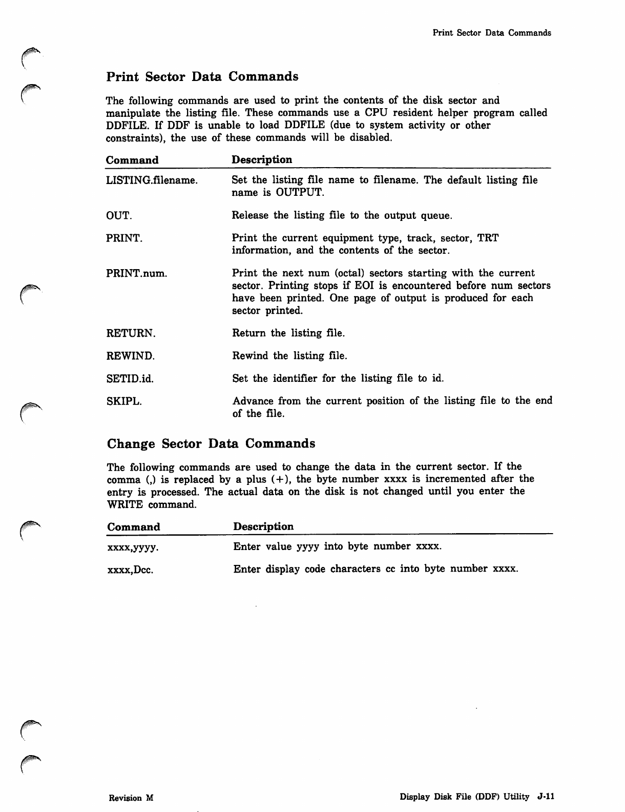
Print Sector Data Commands
Print Sector Data Commands
The following commands are used to print the contents of the disk sector and
manipulate the listing file. These commands use a CPU resident helper program called
DDFILE. If DDF is unable to load DDFILE (due to system activity or other
constraints), the use of these commands will be disabled.
Command
LISTING.filename.
OUT.
PRINT.
PRINT.num.
RETURN.
REWIND.
SETID.id.
SKIPL.
Description
Set the listing file name to filename. The default listing file
name is OUTPUT.
Release the listing file to the output queue.
Print the current equipment type, track, sector, TRT
information, and the contents of the sector.
Print the next num (octal) sectors starting with the current
sector. Printing stops if EOI is encountered before num sectors
have been printed. One page of output is produced for each
sector printed.
Return the listing file.
Rewind the listing file.
Set the identifier for the listing file to id.
Advance from the current position of the listing file to the end
of the file.
Change Sector Data Commands
The following commands are used to change the data in the current sector. If the
comma (,) is replaced by a plus (+), the byte number xxxx is incremented after the
entry is processed. The actual data on the disk is not changed until you enter the
WRITE command.
/$SS$fcS Command
xxxx.yyyy.
xxxx,Dcc.
Description
Enter value yyyy into byte number xxxx.
Enter display code characters cc into byte number xxxx.
Revision M Display Disk File (DDF) Utility J-ll
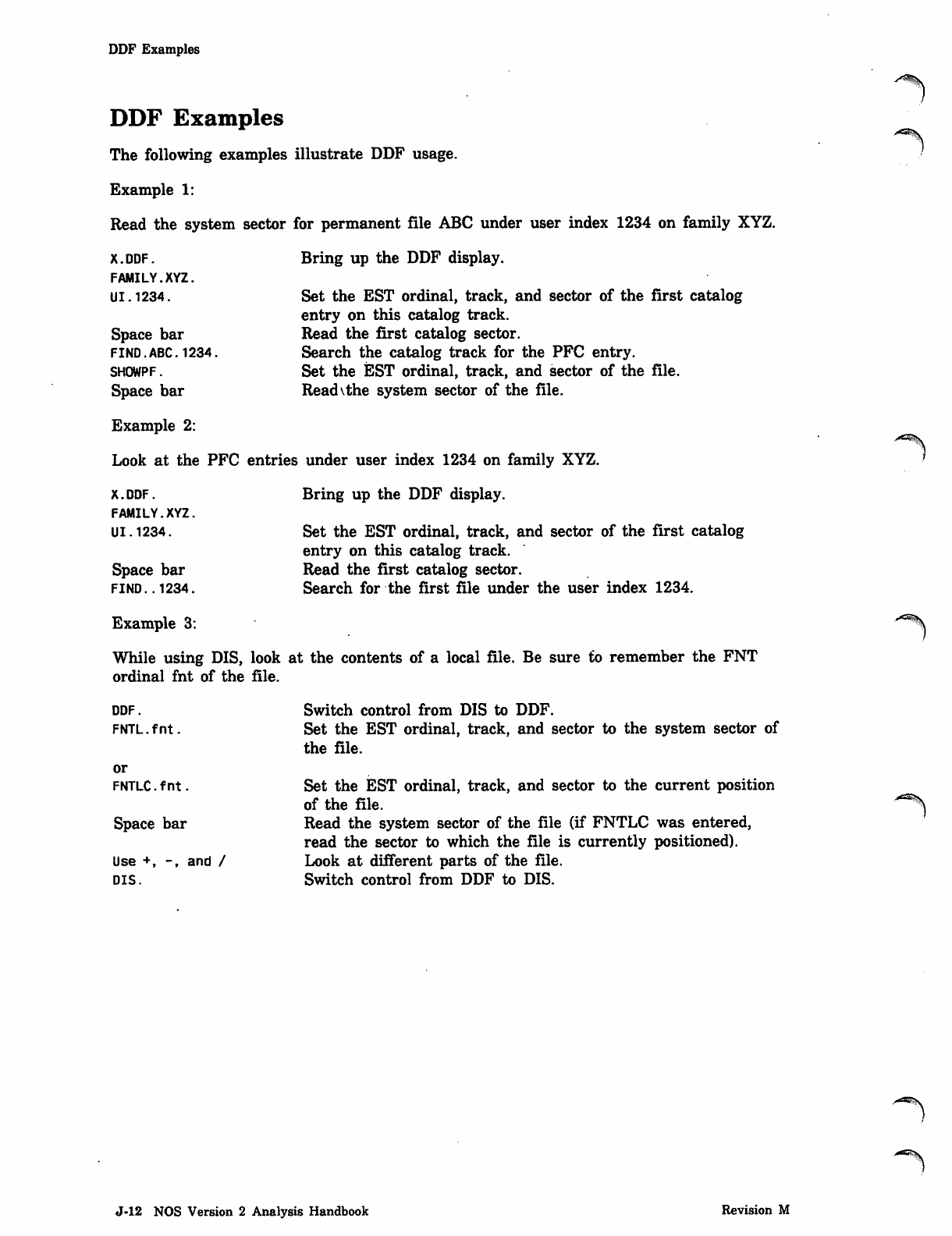
DDF Examples
DDF Examples
The following examples illustrate DDF usage.
Example 1:
Read the system sector for permanent file ABC under user index 1234 on family XYZ.
x.DDF. Bring up the DDF display.
FAMILY.XYZ.
U1.1234. Set the EST ordinal, track, and sector of the first catalog
entry on this catalog track.
Space bar Read the first catalog sector.
FIND.ABC. 1234. Search the catalog track for the PFC entry.
SHOWPF. Set the EST ordinal, track, and sector of the file.
Space bar Readvthe system sector of the file.
Example 2:
Look at the PFC entries under user index 1234 on family XYZ.
x.DDF. Bring up the DDF display.
FAMILY.XYZ.
U1.1234. Set the EST ordinal, track, and sector of the first catalog
entry on this catalog track.
Space bar Read the first catalog sector.
FIND.. 1234. Search for the first file under the user index 1234.
Example 3: *^
While using DIS, look at the contents of a local file. Be sure to remember the FNT
ordinal fnt of the file.
Switch control from DIS to DDF.
Set the EST ordinal, track, and sector to the system sector of
the file.
Set the EST ordinal, track, and sector to the current position
o f t h e fi l e . ^
Read the system sector of the file (if FNTLC was entered,
read the sector to which the file is currently positioned).
Look at different parts of the file.
Switch control from DDF to DIS.
DDF.
FNTL.fnt.
or
FNTLC. f n t .
Space bar
Use +, -, and /
DIS.
J-12 NOS Version 2 Analysis Handbook Revision M
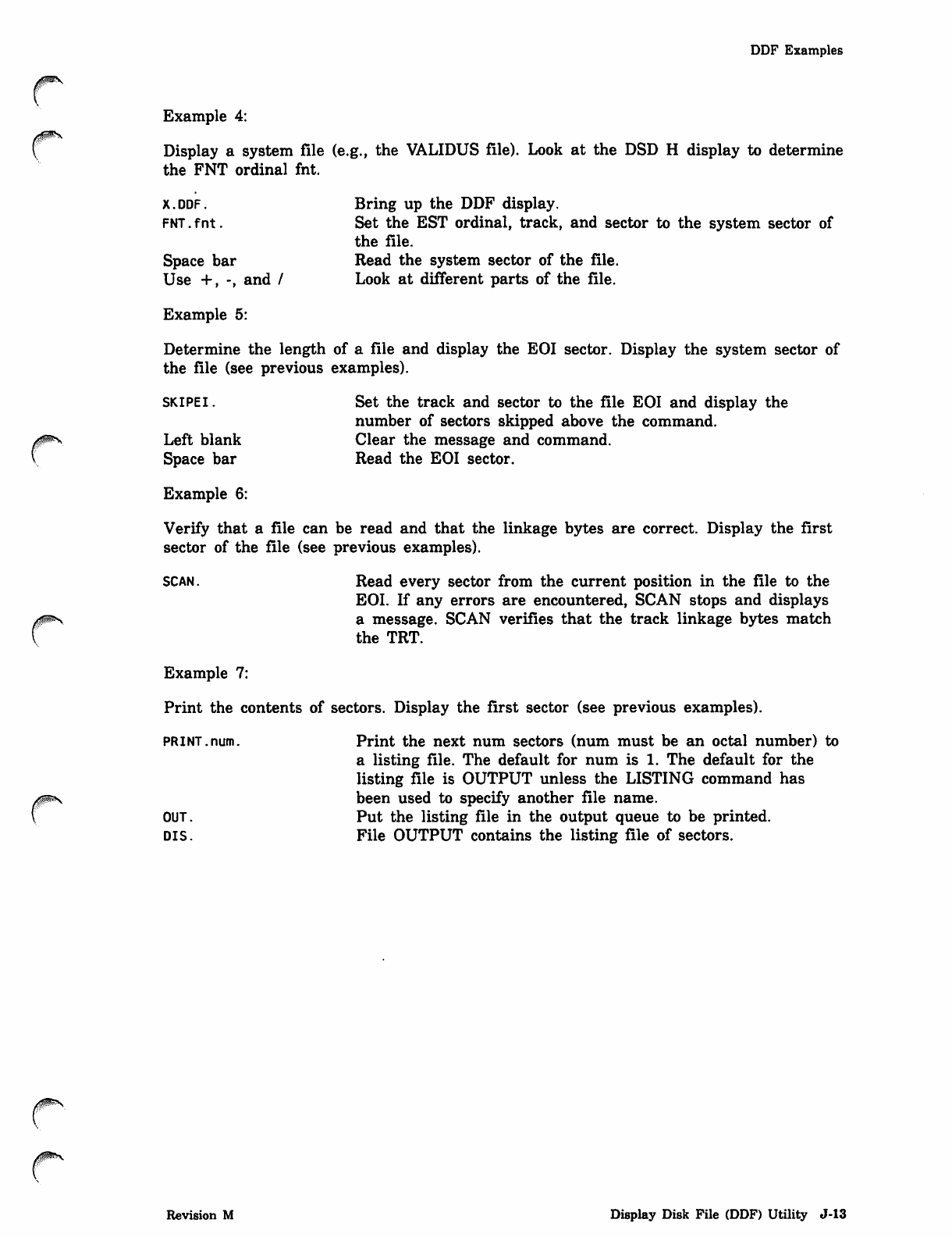
DDF Examples
Example 4:
Display a system file (e.g., the VALIDUS file). Look at the DSD H display to determine
the FNT ordinal fnt.
x.DDF. Bring up the DDF display.
FNT.fnt. Set the EST ordinal, track, and sector to the system sector of
the file.
Space bar Read the system sector of the file.
Use +, -, and / Look at different parts of the file.
Example 5:
Determine the length of a file and display the EOI sector. Display the system sector of
the file (see previous examples).
SKIPEI. Set the track and sector to the file EOI and display the
number of sectors skipped above the command.
Left blank Clear the message and command.
S p a c e b a r R e a d t h e E O I s e c t o r .
Example 6:
Verify that a file can be read and that the linkage bytes are correct. Display the first
sector of the file (see previous examples).
SCAN. Read every sector from the current position in the file to the
EOI. If any errors are encountered, SCAN stops and displays
a message. SCAN verifies that the track linkage bytes match
the TRT.
Example 7:
Print the contents of sectors. Display the first sector (see previous examples).
PR I NT. num. Print the next num sectors (num must be an octal number) to
a listing file. The default for num is 1. The default for the
listing file is OUTPUT unless the LISTING command has
been used to specify another file name.
OU T. P u t t he li s ti ng file in th e o u tp u t q ue u e to be pri nte d.
DIS. File OUTPUT contains the listing file of sectors.
Revision M Display Disk File (DDF) Utility J-13
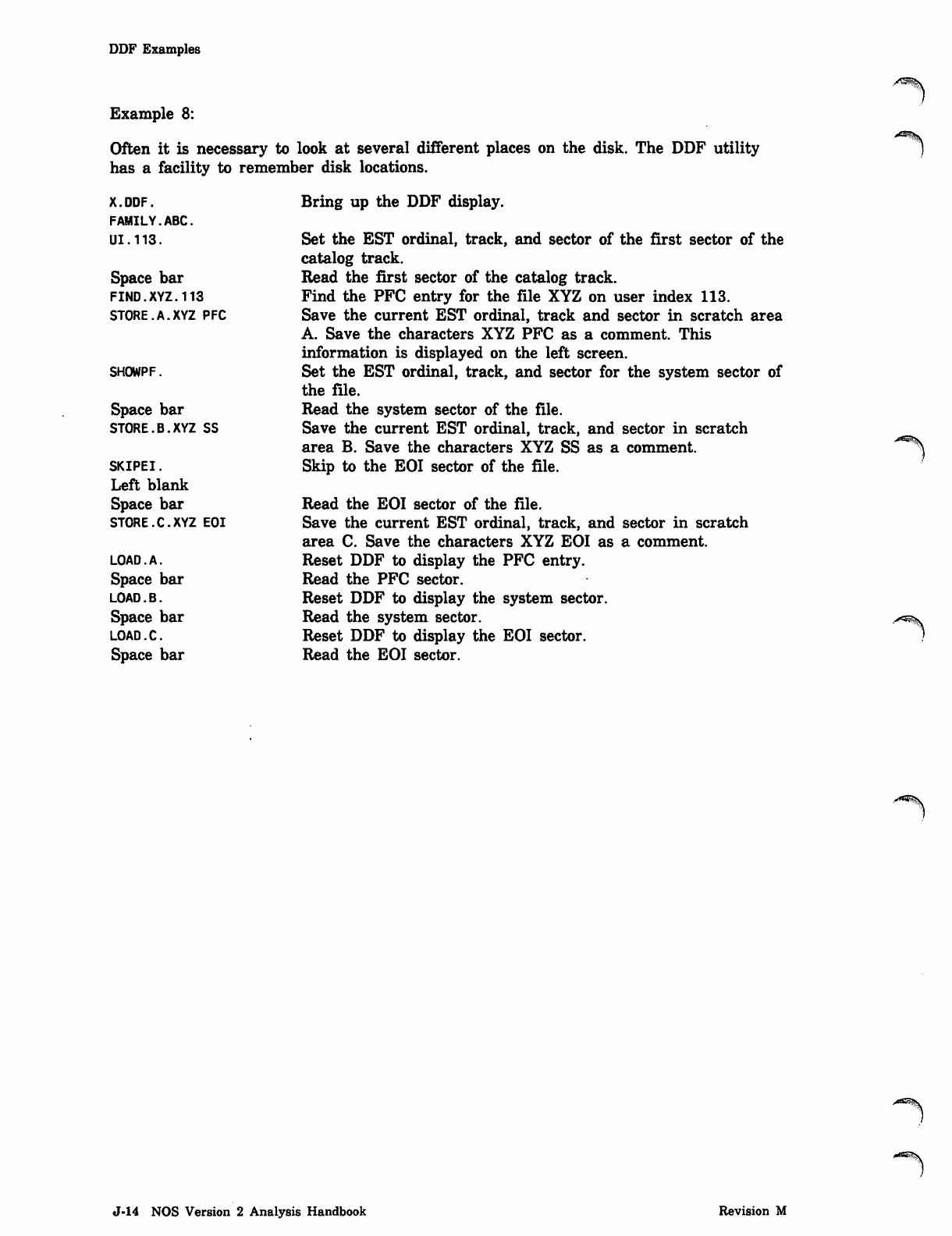
DDF Examples
X.DDF.
FAMILY.ABC.
UI.113.
Space bar
FIND.XYZ.113
STORE.A.XYZ PFC
Example 8:
Often it is necessary to look at several different places on the disk. The DDF utility
has a facility to remember disk locations.
Bring up the DDF display.
Set the EST ordinal, track, and sector of the first sector of the
catalog track.
Read the first sector of the catalog track.
Find the PFC entry for the file XYZ on user index 113.
Save the current EST ordinal, track and sector in scratch area
A. Save the characters XYZ PFC as a comment. This
information is displayed on the left screen.
Set the EST ordinal, track, and sector for the system sector of
the file.
Read the system sector of the file.
Save the current EST ordinal, track, and sector in scratch
area B. Save the characters XYZ SS as a comment.
Skip to the EOI sector of the file.
Read the EOI sector of the file.
Save the current EST ordinal, track, and sector in scratch
area C. Save the characters XYZ EOI as a comment.
Reset DDF to display the PFC entry.
Read the PFC sector.
Reset DDF to display the system sector.
Read the system sector.
Reset DDF to display the EOI sector.
Read the EOI sector.
SHOWPF.
Space bar
STORE.B.XYZ SS
SKIPEI.
Left blank
Space bar
STORE.C.XYZ EOI
LOAD.A.
Space bar
LOAD.B.
Space bar
LOAD.C.
Space bar
J-14 NOS Version 2 Analysis Handbook Revision M
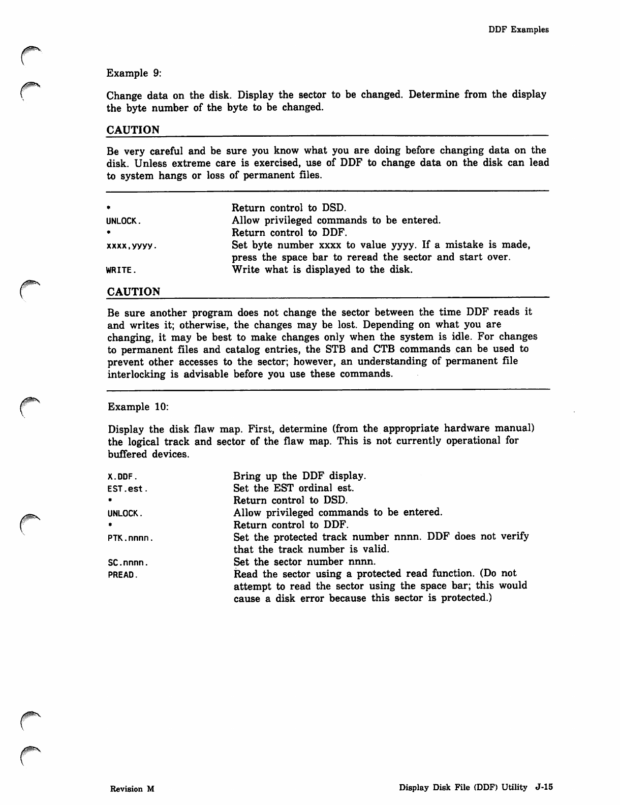
/ffl^^V
DDF Examples
Example 9:
Change data on the disk. Display the sector to be changed. Determine from the display
the byte number of the byte to be changed.
CAUTION
Be very careful and be sure you know what you are doing before changing data on the
disk. Unless extreme care is exercised, use of DDF to change data on the disk can lead
to system hangs or loss of permanent files.
UNLOCK,
xxxx,yyyy.
WRITE.
CAUTION
Return control to DSD.
Allow privileged commands to be entered.
Return control to DDF.
Set byte number xxxx to value yyyy. If a mistake is made,
press the space bar to reread the sector and start over.
Write what is displayed to the disk.
Be sure another program does not change the sector between the time DDF reads it
and writes it; otherwise, the changes may be lost. Depending on what you are
changing, it may be best to make changes only when the system is idle. For changes
to permanent files and catalog entries, the STB and CTB commands can be used to
prevent other accesses to the sector; however, an understanding of permanent file
interlocking is advisable before you use these commands.
Example 10:
Display the disk flaw map. First, determine (from the appropriate hardware manual)
the logical track and sector of the flaw map. This is not currently operational for
buffered devices.
X.DDF.
EST.est.
UNLOCK.
PTK.nnnn
SC.nnnn.
PREAD.
Bring up the DDF display.
Set the EST ordinal est.
Return control to DSD.
Allow privileged commands to be entered.
Return control to DDF.
Set the protected track number nnnn. DDF does not verify
that the track number is valid.
Set the sector number nnnn.
Read the sector using a protected read function. (Do not
attempt to read the sector using the space bar; this would
cause a disk error because this sector is protected.)
Revision M Display Disk File (DDF) Utility J-15
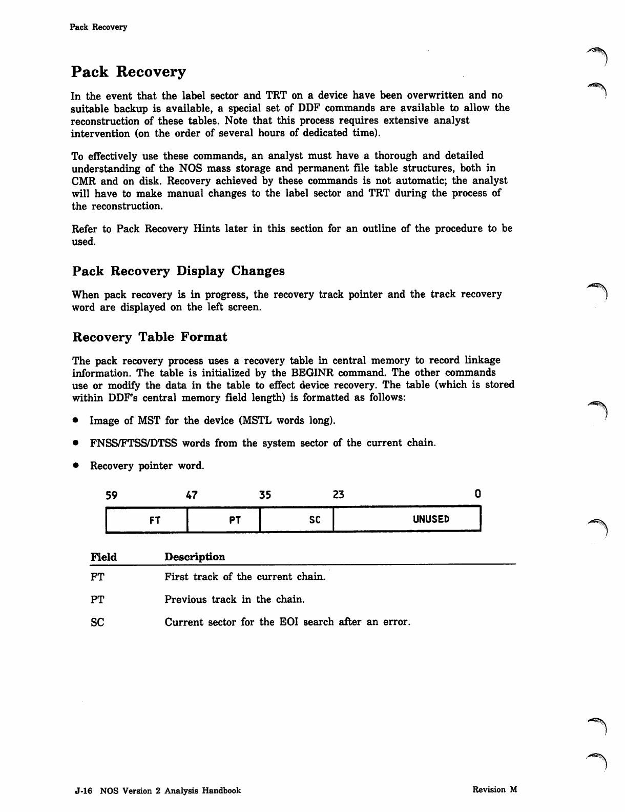
Pack Recovery
Pack Recovery
In the event that the label sector and TRT on a device have been overwritten and no
suitable backup is available, a special set of DDF commands are available to allow the
reconstruction of these tables. Note that this process requires extensive analyst
intervention (on the order of several hours of dedicated time).
To effectively use these commands, an analyst must have a thorough and detailed
understanding of the NOS mass storage and permanent file table structures, both in
CMR and on disk. Recovery achieved by these commands is not automatic; the analyst
will have to make manual changes to the label sector and TRT during the process of
the reconstruction.
Refer to Pack Recovery Hints later in this section for an outline of the procedure to be
used.
Pack Recovery Display Changes
When pack recovery is in progress, the recovery track pointer and the track recovery j
word are displayed on the left screen.
Recovery Table Format
The pack recovery process uses a recovery table in central memory to record linkage
information. The table is initialized by the BEGINR command. The other commands
use or modify the data in the table to effect device recovery. The table (which is stored
within DDF's central memory field length) is formatted as follows:
• Image of MST for the device (MSTL words long).
• FNSS/FTSS/DTSS words from the system sector of the current chain.
• Recovery pointer word.
59 vr 35 23
FT PT SC UNUSED
FieId Description
./*-fev
FT First track of the current chain.
PT Previous track in the chain.
SC Current sector for the EOI search after an error.
<"**5!\
J-16 NOS Version 2 Analysis Handbook Revision M
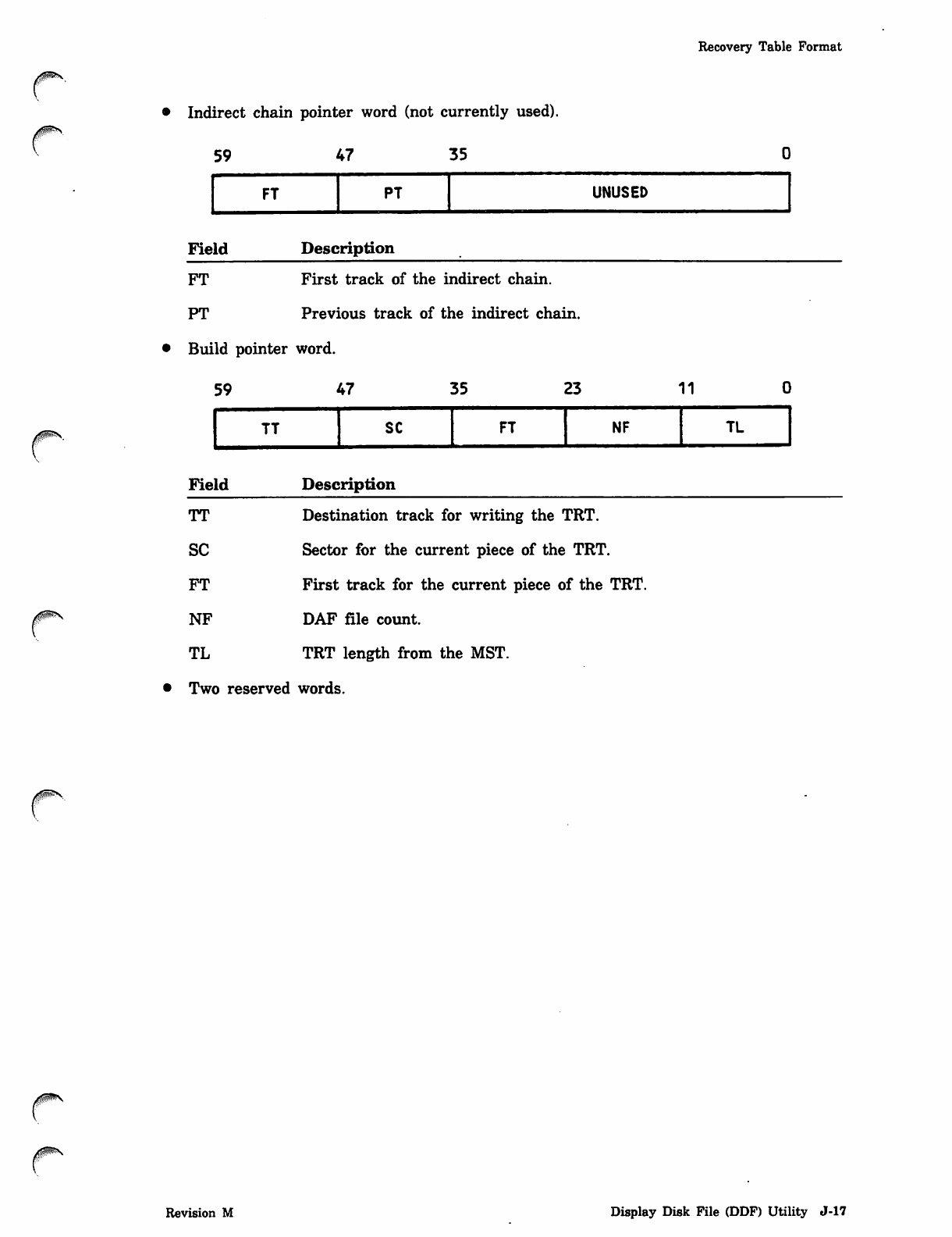
Recovery Table Format
Indirect chain pointer word (not currently used).
5 9 4 7 3 5
FT PT UNUSED
Field Description
FT First track of the indirect chain.
PT Previous track of the indirect chain.
• Build pointer word.
5 9 4 7 3 5 2 3 11
TT SC FT NF TL
Field Description
TT
SC
FT
NF
TL
Destination track for writing the TRT.
Sector for the current piece of the TRT.
First track for the current piece of the TRT.
DAF file count.
TRT length from the MST.
Two reserved words.
Revision M Display Disk File (DDF) Utility J-17
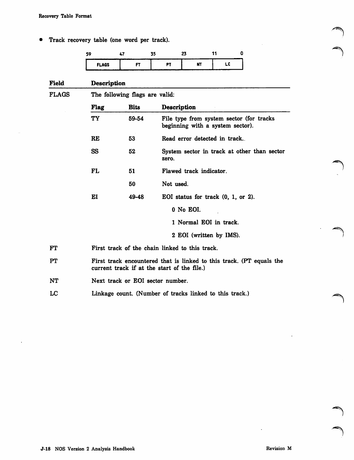
Recovery Table Format
Track recovery table (one word per track).
Field
FLAGS
FT
PT
NT
LC
59 47 35 23 11
FLAGS FT PT NT LC
Description
The following flags are valid:
Flag Bits Description
TY 59-54
RE 53
SS 52
FL 51
50
EI 49-48
File type from system sector (for tracks
beginning with a system sector).
Read error detected in track..
System sector in track at other than sector
zero.
Flawed track indicator.
Not used.
EOI status for track (0, 1, or 2).
0 No EOI.
1 Normal EOI in track.
2 EOI (written by IMS).
First track of the chain linked to this track.
First track encountered that is linked to this track. (PT equals the
current track if at the start of the file.)
Next track or EOI sector number.
Linkage count. (Number of tracks linked to this track.) /<«S^V
J-18 NOS Version 2 Analysis Handbook Revision M
Pack Recovery Commands
Pack Recovery Commands
The BEGINR command must be entered as the first command of a pack recovery
sequence; until the BEGINR command is entered, none of the other pack recovery
commands will be accepted. All of these commands require that the keyboard be
unlocked.
Command Description
BEGINR.
0ms
BLDSL.
BLDSTRT.
BLDSTRT.nnnn.
Begin track recovery for the current selected equipment. The
equipment to be recovered must be removable and unloaded.
The MST in CMR for the selected equipment is used to
initialize the MST for the label track built by the recovery
commands. Be sure the equipment mnemonic in the E,M
display matches that of the pack to be recovered. (The
correct mnemonic can be set with the DSD INITIALIZE
command.)
The first use of this command initializes the recovery
process by:
• Setting the recovery track pointer to zero.
• Reserving and clearing the central memory (CM)
recovery table.
• Setting up the MST skeleton in the recovery table.
• Enabling the use of the other recovery commands.
If the BEGINR command is used again, recovery restarts for
the current equipment.
Build a label sector image in the data buffer from data in
the CM recovery table. Once the other recovery commands
have completed, memory change commands can be used to
fill in any missing data. The buffer can then be written to
disk using the WRITE command.
Build the next sector of the TRT data for the label track.
The track and sector are set for the WRITE command. If
any linkage errors are detected, the message ERROR IN
TRACK STATUS is issued. After the last sector is built, the
pointers are reset to the first sector again. You must
manually generate the EOI sector for the label track using
the BLDEOI command.
Build sector number nnnn of the TRT data for the label
track (nnnn ^ 1).
Revision M Display Disk File (DDF) Utility J-19
Pack Recovery Commands
Command Description
NEXTAT.
NEXTSS.
RECOVER.RECOVER.c.
SETRW.b.nnnn.
SETTP.nnnn.
Locate the next available track on the current equipment
and read the first sector of that track. The search begins at
the displayed recovery track pointer +1. By resetting the
track pointer to track zero and using this command,
unreserved tracks can be found and checked for being part
of the catalog track chain or the indirect access file chain.
Locate the next track in the recovery table that begins with
a system sector. The search begins at the displayed recovery
track pointer +1.
Scan the entire device, saving linkage information in the
track recovery table. The first sector of each track is read
until a system sector is found. For non-SYFT system sectors
and for SYFT files other than DATA, read each sector
(following the sector linkage) until either an EOI sector, a
multiple linkage, an embedded system sector, or a read
error is encountered. For SYFT files LABEL, DATA, and
PERMIT, set the ALGL track pointer in the MST skeleton.
If the scan stops for any reason, it can be restarted by
entering either the RECOVER or RECOVER.c command
(where c is any character). Entering RECOVER.c resumes
the linkage chain scanning from the sector after the one in
which the scan stopped. Entering RECOVER causes DDF to
go back to the last track on which a system sector was
found, advance the track by one, and resume scanning the
first sector of each track looking for another system sector.
Once the RECOVER command has been used to scan the
entire device (which may take several hours) the other
commands can be used to resolve any linkage conflicts or
other loose ends that remain.
NOTE
DDF releases the display to DSD while executing the
RECOVER command to improve performance (minimize lost
revolutions). The display is automatically rerequested when
the scan stops for any reason.
Change byte b of the current track recovery word to number
nnnn. This is the method used to resolve linkage conflicts
before using the BLDSL and BLDSTRT commands.
Set the recovery track pointer for the RECOVER, NEXTAT,
NEXTSS, and SETRW commands to track number nnnn.
J-20 NOS Version 2 Analysis Handbook Revision M
Pack Recovery Hints
0ms
0ms
Pack Recovery Hints
The general process for recovering a pack is as follows:
Example Explanation
BEGINR.
RECOVER. Repeat as many times as required.
SETRW. Repeat as necessary to correct linkage conflicts and oversights.
BLDSL.
WRITE.
BLDSTRT. Repeat until TRT is complete.
WRITE. Repeat until TRT is complete.
S C . n n n n . S e t E O I s e c t o r a d d r e s s .
BLDEOI.
WRITE.
There are, however, several manual operations required in addition to the process
outlined above.
• Several fields in the MST image in the label sector must be entered manually after
the BLDSL command and before the WRITE command. These include:
- Family/pack name.
- Device number.
- Device masks.
- Number of catalog tracks.
• The catalog tracks are not automatically recovered. The NEXTAT command can be
used to search for the catalog tracks after the device has been completely scanned
by the RECOVER command. In general, the catalog tracks are allocated on a device
immediately prior to the first track of the indirect chain. (The first track of the
indirect chain can be found by checking byte 0 of ALGL in the MST, built by the
BLDSL command.) Once the catalog tracks are found, the track linkage information
for these tracks must be set in the track recovery words by using the SETRW
command.
The label track must be linked to the first catalog track, which is linked to the
second original catalog track, which is linked to the third original catalog track,
and so forth. All overflow catalog tracks are linked after the last of the original
catalog tracks.
There can be one or more overflow catalog tracks for each of the original catalog
tracks. These overflow tracks are linked from their corresponding catalog track via
the sector linkage in the last sector of that track. This means that the sector
linkage does not correspond to the TRT linkage for these tracks.
Revision M Display Disk File (DDF) Utility J-21
Pack Recovery Hints
y*^|\
The indirect chain is not automatically recovered. Tracks in the indirect chain can
be located using the NEXTAT command and the RECOVER.c or FINDISS ^^
commands. Tracks for which bit 52 is set in the recovery word (which indicates )
that a system sector was found in a sector other than sector zero on this track) are
probably part of the indirect chain. Examining the sector linkage of the last sector
of each track that has been identified as containing indirect access file data can be
used to establish the ordering of these tracks. Note that if the last sector of an
indirect chain track is a system sector, byte NSSS contains the pointer to the next
track. Alternatively, the PFCs on the catalog tracks can be examined to determine
the tracks that are on the indirect chain and the ordering of these tracks.
Instances in which multiple tracks are linked to a single track in the track
recovery table must be resolved in order to correctly build the TRT. Note that the
BLDSTRT command will inform you of these conflicts. You must inspect the
contents of the various tracks and make an empirical judgment as to the correct
linkage.
The SETRW and SETTP commands must be used to eliminate the conflicting
linkage. If a track is to be left unreserved, its track recovery word should be
zeroed.
Flawed tracks may be indicated by setting the flawed track indicator (FL flag) in
the track recovery word for that track.
A ^ S
^ms
J-22 NOS Version 2 Analysis Handbook Revision M
Jp^*-
y$m\
PACKER Utility K
The PACKER utility enables you to manage holes within the indirect access permanent
file chain (IAPF chain) on a permanent file device. This chain is the set of tracks that
contains all the indirect access permanent files on a permanent file device. Space
within the chain is allocated to individual files.
Holes are the spaces created within the IAPF chain when indirect access permanent
files are deleted. These spaces may be reused later for other indirect access permanent
files; however, over time these spaces tend to become fragmented into smaller and
smaller pieces. Eventually, a large amount of space may be in small, unusable holes.
The PACKER utility reorganizes the IAPF chain so that more of the holes are
available for storage. It combines adjacent holes, moves files to allow holes to be
combined, and releases entire tracks when possible. These actions make more tracks
available on the device (relieving a TRACK LIMIT condition, if one exists) as well as
making the remaining holes larger and thus more usable.
Operational Overview
A single call to the PACKER utility only processes a single permanent file device, but
you can process multiple devices at the same time by calling a different copy of
PACKER for each device.
NOTE
While PACKER is processing a device, no other files are allowed to access that device.
PACKER begins processing a device by reading all the permanent file catalog entries
(PFC entries) on the specified device and building a set of tables that allows it to
operate on the IAPF chain in sequential order. PACKER then scans the IAPF chain
from the beginning, searching for holes.
Lost Space Processing
If PACKER encounters any lost space during its scan, it attempts to reclaim the space
for future use. Lost space is a condition where space exists on the IAPF chain that is
not pointed to by a permanent file catalog (PFC) entry. Without a PFC entry, the
permanent file manager (PFM) is unaware of the space. Lost space is usually the
result of a previous PACKER run being interrupted by a system failure.
If the lost space is preceded by or followed by a hole, PACKER merges the lost space
with one of the holes. If the lost space is preceded by a file and not followed by a hole,
PACKER creates a new PFC entry for it, transforming it into a normal IAPF hole. If
the lost space is smaller than the absolute minimum IAPF hole size of three PRUs, it
cannot be reclaimed and is left as lost space.
Revision M PACKER Utility K-l
Hole Processing
Hole Processing
When PACKER encounters a hole during its scan, a sequence of events begins. Unless
the collection hole is already open, the newly found hole is turned into the collection
hole. The collection hole is the focal point of the major operations of combining holes
and moving files. The PFC pointing to the collection hole is changed into a purged
direct access permanent file (DAPF) PFC. This PFC is changed back into an IAPF PFC
pointing to the hole when the collection hole is changed back into a normal hole; until
that occurs, the collection hole is lost space.
PACKER uses this procedure to provide for system failures during PACKER operation.
If such a failure occurs, the system is unaware of the changes PACKER is making, all
files are intact, and the lost space is recovered the next time PACKER is run.
The following sequence is repeated until the collection hole is closed.
1. Any holes following the collection hole have their PFCs changed into purged DAPF
PFCs and their space is added to the collection hole. This combining of contiguous
holes is continued until PACKER encounters a file.
2. When a file is encountered, PACKER checks to see if the collection hole is big
enough for tracks to be delinked from it. If so, it delinks and returns the tracks to
the system. This premove delinking limits the amount of data (files) that are moved
by limiting the size of the collection hole.
3. The utility looks for the largest file that fits into the collection hole by starting
from the end of the IAPF chain and scanning toward the current position. If it
finds such a file, PACKER copies the file to the beginning of the collection hole,
updates its PFC to point to the new position, and updates the collection hole's
starting address and length. (This is called the fill-move technique.)
If the collection hole is completely filled, PACKER considers it closed and begins
scanning again. If the move is successful, PACKER repeats it until no further files
can be moved using the fill-move technique.
4. The file adjacent to the collection hole (which was excluded from the fill-move
search) is then examined to see if it can be slid across the collection hole. This file
must completely fit within the collection hole, for the file would be destroyed if the
file was copied on top of itself and the system failed during the copy.
PACKER examines the sizes of all the files until the next hole to ensure that they
fit in the collection hole (if any do not fit, the effect of the moves would only be to
move the position of the hole, which in itself is of no benefit).
If all the files fit, PACKER copies them, one by one, across the collection hole, and
updates the address of the collection hole. (This is called the slide-move technique.)
PACKER combines the newly adjacent hole with the collection hole and resumes
scanning. If all the files between the collection hole and the next hole do not fit
into the collection hole, PACKER closes the collection hole and scans for the next
hole.
5. PACKER terminates the scan when it encounters the end of the IAPF chain. If the
collection hole is open, PACKER drops it off the end of the IAPF chain by adjusting
the EOI.
K-2 NOS Version 2 Analysis Handbook Revision M
Dayfile Statistics
Dayfile Statistics
At termination, PACKER issues the following set of statistical dayfile messages. These
messages document the original state of the device, changes made by PACKER, final
state of the device, and resources used by PACKER.
ONSET FILES NNNNNN, SSSSSS PRUS
ONSET HOLES NNNNNN, SSSSSS PRUS
FILL MOVES NNNNNN, SSSSSS PRUS
SLIDE MOVES NNNNNN, SSSSSS PRUS
FILES MOVED NNNNNN, SSSSSS PRUS
LOST SPACE NNNNNN, SSSSSS PRUS
HOLES LEFT NNNNNN, SSSSSS PRUS
HOLES FREED NNNNNN, SSSSSS PRUS
TRACKS FREED NNNNNN, SSSSSS PRUS
FLAW SPACE NNNNNN, SSSSSS PRUS
SRUS 23456.890 UNTS.
CPU SECONDS 23456.890 SECS.
MAXIMUM CM FL 234567890 SCM.
MANAGED TABLE MOVES 234567890 UNTS.
/0ms
Revision M PACKER Utility K-3
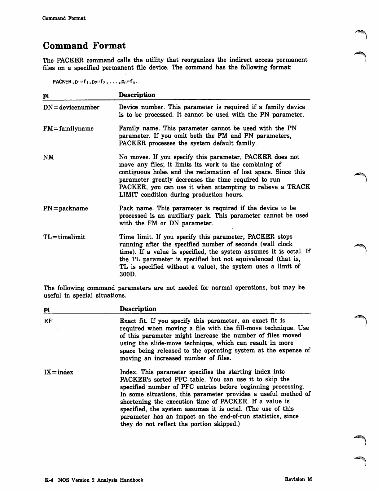
Command Format
Command Format
The PACKER command calls the utility that reorganizes the indirect access permanent
files on a specified permanent file device. The command has the following format:
PACKER,Pi=f1,p2=f2. • • • .Pn=f*rv
Pi Description
DN=devicenumber
FM=familyname
NM
Device number. This parameter is required if a family device
is to be processed. It cannot be used with the PN parameter.
Family name. This parameter cannot be used with the PN
parameter. If you omit both the FM and PN parameters,
PACKER processes the system default family.
No moves. If you specify this parameter, PACKER does not
move any files; it limits its work to the combining of
contiguous holes and the reclamation of lost space. Since this
parameter greatly decreases the time required to run
PACKER, you can use it when attempting to relieve a TRACK
LIMIT condition during production hours.
Pack name. This parameter is required if the device to be
processed is an auxiliary pack. This parameter cannot be used
with the FM or DN parameter.
Time limit. If you specify this parameter, PACKER stops
running after the specified number of seconds (wall clock
time). If a value is specified, the system assumes it is octal. If
the TL parameter is specified but not equivalenced (that is,
TL is specified without a value), the system uses a limit of
300D.
The following command parameters are not needed for normal operations, but may be
useful in special situations.
PN=packname
TL=timelimit
Pi Description
EF
IX=index
Exact fit. If you specify this parameter, an exact fit is
required when moving a file with the fill-move technique. Use
of this parameter might increase the number of files moved
using the slide-move technique, which can result in more
space being released to the operating system at the expense of
moving an increased number of files.
Index. This parameter specifies the starting index into
PACKER'S sorted PFC table. You can use it to skip the
specified number of PFC entries before beginning processing.
In some situations, this parameter provides a useful method of
shortening the execution time of PACKER. If a value is
specified, the system assumes it is octal. (The use of this
parameter has an impact on the end-of-run statistics, since
they do not reflect the portion skipped.)
K-4 NOS Version 2 Analysis Handbook Revision M
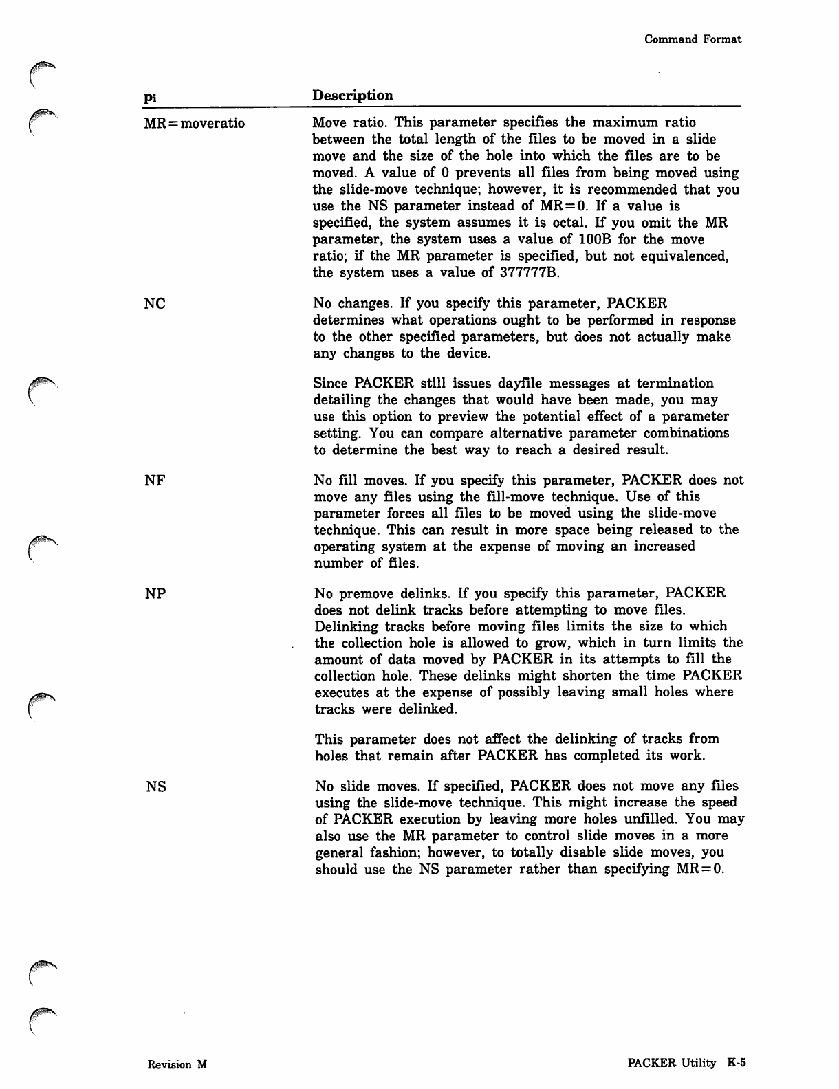
Command Format
pi Description
0m^**
f MR=moveratio Move ratio. This parameter specifies the maximum ratio
between the total length of the files to be moved in a slide
move and the size of the hole into which the files are to be
moved. A value of 0 prevents all files from being moved using
the slide-move technique; however, it is recommended that you
use the NS parameter instead of MR=0. If a value is
specified, the system assumes it is octal. If you omit the MR
parameter, the system uses a value of 100B for the move
ratio; if the MR parameter is specified, but not equivalenced,
the system uses a value of 377777B.
NC No changes. If you specify this parameter, PACKER
determines what operations ought to be performed in response
to the other specified parameters, but does not actually make
any changes to the device.
Since PACKER still issues dayfile messages at termination
detailing the changes that would have been made, you may
use this option to preview the potential effect of a parameter
setting. You can compare alternative parameter combinations
to determine the best way to reach a desired result.
NF No fill moves. If you specify this parameter, PACKER does not
move any files using the fill-move technique. Use of this
parameter forces all files to be moved using the slide-move
technique. This can result in more space being released to the
operating system at the expense of moving an increased
number of files.
NP No premove delinks. If you specify this parameter, PACKER
does not delink tracks before attempting to move files.
Delinking tracks before moving files limits the size to which
the collection hole is allowed to grow, which in turn limits the
amount of data moved by PACKER in its attempts to fill the
collection hole. These delinks might shorten the time PACKER
executes at the expense of possibly leaving small holes where
tracks were delinked.
This parameter does not affect the delinking of tracks from
holes that remain after PACKER has completed its work.
NS No slide moves. If specified, PACKER does not move any files
using the slide-move technique. This might increase the speed
of PACKER execution by leaving more holes unfilled. You may
also use the MR parameter to control slide moves in a more
general fashion; however, to totally disable slide moves, you
should use the NS parameter rather than specifying MR=0.
0ims
Revision M PACKER Utility K-5
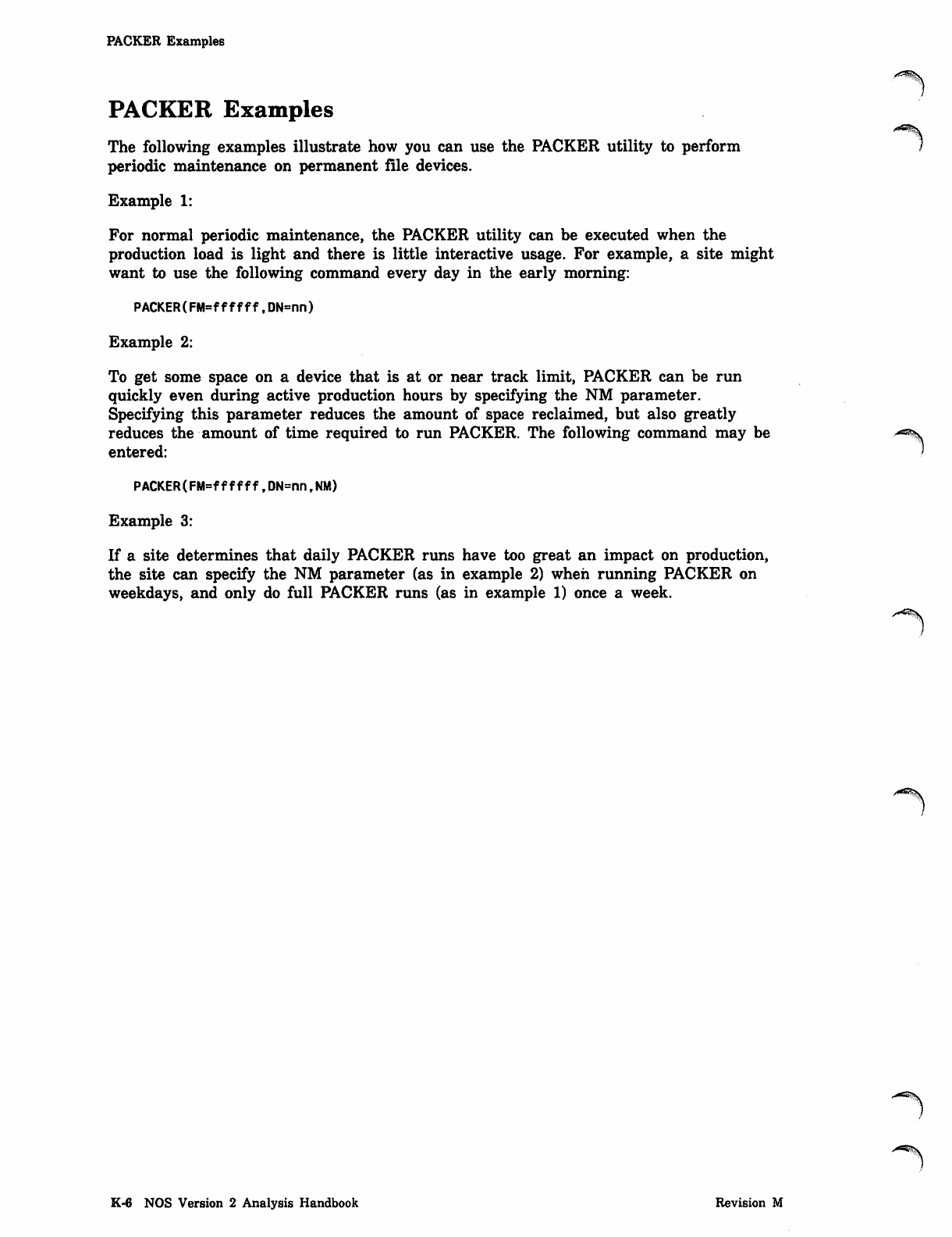
PACKER Examples
PACKER Examples
The following examples illustrate how you can use the PACKER utility to perform
periodic maintenance on permanent file devices.
Example 1:
For normal periodic maintenance, the PACKER utility can be executed when the
production load is light and there is little interactive usage. For example, a site might
want to use the following command every day in the early morning:
PACKER(FM=ffffff,DN=nn)
Example 2:
To get some space on a device that is at or near track limit, PACKER can be run
quickly even during active production hours by specifying the NM parameter.
Specifying this parameter reduces the amount of space reclaimed, but also greatly
reduces the amount of time required to run PACKER. The following command may be
entered:
PAC KER (FM = ffffff, D N=n n,N M)
Example 3:
If a site determines that daily PACKER runs have too great an impact on production,
the site can specify the NM parameter (as in example 2) when running PACKER on
weekdays, and only do full PACKER runs (as in example 1) once a week.
-^s.
K-6 NOS Version 2 Analysis Handbook Revision M


**%■
-K
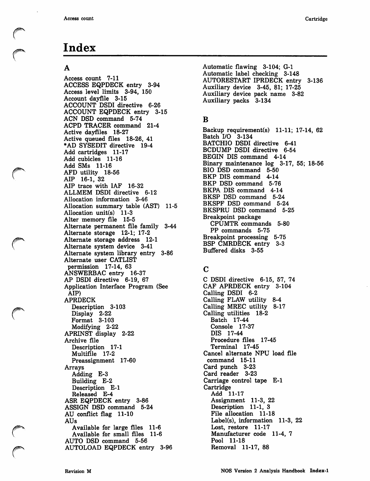
Access count Cartridge
Index
0>^$S
r
Access count 7-11
ACCESS EQPDECK entry 3-94
Access level limits 3-94, 150
Account dayfile 3-15
ACCOUNT DSDI directive 6-26
ACCOUNT EQPDECK entry 3-15
ACN DSD command 5-74
ACPD TRACER command 21-4
Active dayfiles 18-27
Active queued files 18-26, 41
*AD SYSEDIT directive 19-4
Add cartridges 11-17
Add cubicles 11-16
Add SMs 11-16
AFD utility 18-56
AIP 16-1, 32
AIP trace with IAF 16-32
ALLMEM DSDI directive 6-12
Allocation information 3-46
Allocation summary table (AST) 11-5
Allocation unit(s) 11-3
Alter memory file 15-5
Alternate permanent file family 3-44
Alternate storage 12-1; 17-2
Alternate storage address 12-1
Alternate system device 3-41
Alternate system library entry 3-86
Alternate user CATLIST
permission 17-14, 63
ANSWERBAC entry 16-37
AP DSDI directive 6-19, 67
Application Interface Program (See
AIP)
APRDECK
Description 3-103
Display 2-22
Format 3-103
Modifying 2-22
APRINST display 2-22
Archive file
Description 17-1
Multifile 17-2
Preassignment 17-60
Arrays
Adding E-3
Building E-2
Description E-l
Released E-4
ASR EQPDECK entry 3-86
ASSIGN DSD command 5-24
AU conflict flag 11-10
AUs
Available for large files 11-6
Available for small files 11-6
AUTO DSD command 5-56
AUTOLOAD EQPDECK entry 3-96
Automatic flawing 3-104; G-l
Automatic label checking 3-148
AUTORESTART IPRDECK entry 3-136
Auxiliary device 3-45, 81; 17-25
Auxiliary device pack name 3-82
Auxiliary packs 3-134
B
Backup requirement(s) 11-11; 17-14, 62
Batch I/O 3-134
BATCHIO DSDI directive 6-41
BCDUMP DSDI directive 6-54
BEGIN DIS command 4-14
Binary maintenance log 3-17, 55; 18-56
BIO DSD command 5-50
BKP DIS command 4-14
BKP DSD command 5-76
BKPA DIS command 4-14
BKSP DSD command 5-24
BKSPF DSD command 5-24
BKSPRU DSD command 5-25
Breakpoint package
CPUMTR commands 5-80
PP commands 5-75
Breakpoint processing 5-75
BSP CMRDECK entry 3-3
Buffered disks 3-55
C DSDI directive 6-15, 57, 74
CAF APRDECK entry 3-104
Calling DSDI 6-2
Calling FLAW utility 8-4
Calling MREC utility 8-17
Calling utilities 18-2
Batch 17-44
Console 17-37
DIS 17-44
Procedure files 17-45
Terminal 17-45
Cancel alternate NPU load file
command 15-11
Card punch 3-23
Card reader 3-23
Carriage control tape E-l
Cartridge
Add 11-17
Assignment 11-3, 22
Description 11-1, 3
File allocation 11-18
Label(s), information 11-3, 22
Lost, restore 11-17
Manufacturer code 11-4, 7
Pool 11-18
Removal 11-17, 88
Revision M NOS Version 2 Analysis Handbook Index-1
Cartridge accessor unit Configuring shared mass storage devices
Restoration 11-87
Serial number 11-69
Cartridge accessor unit 11-1
Cartridge alternate storage
address 17-18, 63
Cartridge alternate storage flags 17-15,
63
Cartridge alternate storage type 17-18,
63
CARTRIDGE PF STAGING IPRDECK
entry 3-136
Catalog archive file (See PFATC)
Catalog entry 17-11
Catalog image record (See CIR)
Catalog information 3-46
Catalog permanent file (See PFCAT)
Catalog track
Chain 17-10
Description 17-9
Entry 17-11
CBT DSDI directive 6-22
CCP files 16-9
CCT DSDI directive 6-22
CC545
Display differences J-3
Keys 4-10, 13, 15; J-4
CC598B
Display differences 5-2; J-3
Keys 4-10, 13, 15; J-4
CC634B
Display differences 5-2; J-3
Keys 4-10, 13, 15; J-4
CDCfiff DSD command 5-50
CDCNET
COP 15-4, 62
Device interface EST entry 3-34
MDI 15-2
NDI 15-2
Network 15-1
TDI 15-4
CDCNET Operator (See COP)
CEF DIS command 4-14
Central memory 3-2
Clearing 3-124
Descriptions 3-3
Reservation 3-7
Resident 3-3
Table of sizes 3-12
Time slice 3-153
Central processor multiplier
(CPM) 3-119
CFO DSD command 5-9
CFO NAM command 15-5
CFR DSD command 5-75
Chain control field 11-10
Change flag, SM map 11-61
Change NPU load file command 15-12
Changing system attributes 9-16, 17
Channel 15-2
Channel control commands 15-74
Character set(s)
Anomalies A-2
Description A-l
Mode A-121
Charge number 17-19, 63
Check mass storage (CMS) routine 3-98
CHECK POINT SYSTEM DSD
command 5-56
Checkpoint, multimainframe 13-9, 16
CIR
Catalog 17-78
Description 17-79
PF utility option 17-55
Circular buffer data structure 16-15
CKP DSD command 5-4
CLASS DSD command 5-10
CLASS IPRDECK entry 3-137
Clear all flaw reservations 3-104
Clear logical flaws 3-105
Clear physical disk area flaws 3-104
Clear physical extended memory
track 3-104
Clear tape unit assignment 3-104
Clear unit reservations 3-96
Clearing permanent file error
flags 11-77
CLF APRDECK entry 3-105
CLT CMRDECK entry 3-4
Cluster control blocks (CCB) 16-17
CM DSDI directive 6-12
*CM SYSEDIT directive 19-3
CMRDECK
Description 3-2
Display 2-3
Entries 3-3
Listing 3-2
Modifying 2-3; 3-1
CMRINST
Description 3-2
Display 2-3
Code conversion parameters 10-13
COLLECT command 16-6
Collection hole K-2
COMLIB IPRDECK entry 3-118
COMMENT DSD command 5-9
Comments 16-14
Common library table 3-4, 118
Common test and initialization
software 7-1
Communications Control Program (See
CCP) 16-9
Communications supervisor (See CS)
Concurrent channel 6-38
Down 5-25
Dump 6-38
PP Dump 6-51
Up 5-47
Concurrent PP 6-46, 51
Configuration information 3-2
Configuring shared mass storage
devices 13-6, 13
r ^ S
Index-2 NOS Version 2 Analysis Handbook Revision M

Connection slot array Debug mode
y^S.
A ^ S .
r
Connection slot array 8-42
Console equipment EST entry 3-58
Console operation under DIS 4-14
Contiguous block data structure 16-15
Continuation AU flag 11-10
CONTINUE DSD command 5-25
Control cartridge allocation 11-18
Control module
Controlware 1-1
EST entry 3-66
Control of jobs 3-110
Control points
Area 3-3
Number 3-8, 111
Usage 3-110
Controller, 7021 block identification 3-29
Controlware
Loading utility 1-1
Status display 2-19
Type 1-1; 3-90
Version number 3-92
Conversion mode, tape 3-129
Coupler
Description 15-2
Disable or enable 15-7
CP DSDI directive 6-28, 58, 68
CPB DSD command 5-78
CPF APRDECK entry 3-106
CPM default values 3-119
CPM IPRDECK entry 3-118
CPO DSDI directive 6-30
CPTT DSD command 5-11
CPTT IPRDECK entry 3-138
CPU job priority 3-139
CPU recall delay 3-139
CPU recall period 3-139
CPUMTR breakpoint
C Display 5-81
Commands 5-80
Precautions 5-83
CPUPFM transfer threshold 3-138
CS
Description 15-1
Information command 15-48
CSM IPRDECK entry 3-121
CT DSDI directive 6-30
Cubicle assignment 11-4
Cubicles 11-1
CYBERPLUS ring port EST entry 3-39
D
D DSDI directive 6-16, 59
Data gathering facility 3-125
Data recording controllers (DRC) 11-1
Data recording drives (DRD) 11-1
Data storage display (F) 4-6
Database control system, CYBER 3-134
DATE DSD command 5-57
Date line 3-8
Date/time entry 2-25
Dayfile
Account 3-15
Commands 5-3
Description 3-15
Dumping utilities 18-1, 56
Dumps 5-3
Error log 3-16
Logging messages 3-142
System 3-16
Termination 18-17, 58
DAYFILE DSDI directive 6-30
DAYFILE EQPDECK entry 3-16
DB DSDI directive 6-30
DBW DSDI directive 6-31
DCH DSD command 5-74
DCN DSD command 5-74
DCP DIS command 5-14
DDB DSDI directive 6-31
DDF
Bringing up J-l
Change sector data commands J-ll
. Commands J-6
Console messages J-5
Description J-l
Examples J-12
Keyboard input J-4
Left screen display J-2
Pack recovery J-l6
Print sector data commands J-ll
Right screen display J-3
DDF DIS command 4-14
DDF pack recovery
Commands J-l6
Display changes J-l6
Hints J-21
Recovery table J-l 6
DDFILE J-ll
DDP rollout path 3-140
DDP ROLLOUT PATH IPRDECK
entry 3-140
Deadstart
Displays 2-9
DSD entry 3-99
Error idle recovery 2-44
Error processing 2-36
Level 0 initial recovery 2-36
Level 1 recovery 2-35
Level 2 recovery 2-34
Level 3 recovery 2-31
Mass storage device 2-38
Preparation 2-28
Process 2-1
Deadstart decks 3-1
Deadstart dump interpreter (See DSDI)
Deadstart file 3-1
Deadstart sequencing 20-4
DEBUG DSD command 5-58
DEBUG IPRDECK entry 3-138
Debug log file processor (DLFP) 16-32
Debug mode 3-138
Revision M NOS Version 2 Analysis Handbook Ind.ex-3
Debugging commands DOWN DSD command
Debugging commands 5-84
Decision algorithm hierarchy 11-34
Default family name assignment
entry 3-87
DELAY DSD command 5-10
DELAY IPRDECK entry 3-139
Delay values, record 5-12
♦DELETE SYSEDIT directive 19-7
DEMUX command 16-52
Destage dump tape
Characteristics 12-3
Data format 12-3
Description 12-1
Destaging files 12-3
Modifying files 12-7
Organization 12-3
Recycling 12-7
Destage/release processing
Algorithms 11-33
Destaging 12-1; 17-3
Excluding 11-32
Destaging files 11-12; 12-3
Device
Auxiliary 3-45
Family 3-46
Link 3-46
Master 3-46
Private 3-45
Public 3-45
Device access table 13-2, 6
Device configuration
Independent SDM 13-13
Linked SDM 13-2
Device index table 13-10, 14
Device initialization options table 8-10
Device mask 3-81; 17-4, 5
DFD utility 18-56
DFLIST routine 18-27
DFPT IPRDECK entry 3-140
DFT CMRDECK entry 3-4
DFTERM routine 18-27
Diagnostic operator (See DOP)
DIAL DSD command 5-8
Direct access files 3-47, 153
Directory display (Z) 4-9
DIS
Commands 4-14
Console operation 4-10
DIS command 4-1
Display identifiers 4-2
Display selection commands 4-13
DSD command 5-58
Keyboard entries 4-14
Keys with special meaning 4-13
Memory displays 4-6
Memory entry commands 4-18
Messages 4-12
Operations 4-1
PP call commands 4-20
* DIS command 4-17
, DIS command 4-17
DIS DIS command 4-14
DIS displays
Data Data storage 4-6
Directory 4-8
Display (A) 4-4
Display (B) 4-4
Display (F) 4-6
Display (G) 4-7
Display (X) 4-8
Display (Z) 4-8
Displays (C, D, F, G) 4-6
Exchange package 4-8
Job dayfile 4-4
Job status 4-4
Memory 4-6
Program storage 4-7
DIS memory displays
DISABLE DSD command 5-59
Disable host element command 15-15
Disable network element
command 15-29
Disable subsystems 3-134
Disk controlware 1-2
Disk equipment EST entry 3-60
Disk file format
Full stripe 11-67
Partial stripe 11-68
Disk flaws (See Storage media defects)
Disk idle mode 1-2
Disk, removable 3-54, 87
Disk space
Detecting failing devices 1-1
Known media defects 1-3
Management 11-11, 35, 79, 86; K-l
Release 11-11; 12-5; 17-57
Disk thresholds display 2-20
DISK VALIDATION IPRDECK
entry 3-121
Display console equipment EST
entry 3-58
Display disk file utility J-l
Display disk file utility (See DDF)
Display identifiers (DIS) 4-2
Display selection commands (DIS) 4-2
Display selection commands (DSD) 5-2
DISPOSE DSDI directive 6-10
Disposition type 18-14, 18, 23
Distributive data path (DDP) 3-68
DMPCCC utility 1-4
DMPNAD utility 14-1
DOP
Commands 15-48
Control commands 15-62
Network control 15-43
Responsibilities 15-4, 43
SEND command 15-54
Status message formats 15-45
Unsolicited status reports 15-48
DOP (See Diagnostic operator)
DOWN channel entry 3-80
DOWN DSD command 5-25
'/<S%y
■^^%.
■^ms
Index-4 NOS Version 2 Analysis Handbook Revision M
DOWN EQPDECK entry Error processing
00$S.
0ms,
DOWN EQPDECK entry 3-80
DP DSDI directive 6-31
DPFC macro E-3
DROP DIS command 4-14
DROP DSD command 5-5
DS equipment EST entry 3-22
DSD commands
Categories 5-1
Description 5-1
DSD IPRDECK entry 3-122
DSDI
Buffer controller directive 6-54
Command 6-3
CRM dump directives 6-26
Description 6-1
Directive format 6-7
Dump hardware registers 6-46
Dump memory 6-12
Dump subsystem 6-41
Dump tape request 6-5
Examples 6-63
Features 6-1
File manipulation and control 6-1
Input directives 6-6
Interactive use 6-55
List control directives 6-8
PP memory dump 6-19
Terminal output directives 6-57
*. DSDI directive 6-9
DSDI (See Deadstart dump interpreter)
Dual-state, NOS-NOS/VE 10-7
Dump
Dayfiles 5-3
Full 11-82; 17-74
Incremental 11-83; 17-73
NOS/VE addresses H-l
Partial 17-74
Secured system 17-73
Tape management 11-35, 83
Dump NAD memory
Description 14-1
Local NAD dumping 14-2
Remote NAD dumping 14-2
E
E DSDI directive 6-16
EC DSDI directive 6-13
EI IPRDECK entry 3-123
EICB DSDI directive 6-31
EJ DSDI directive 6-8
EJOFF DSDI directive 6-8
EJON DSDI directive 6-8
EJT CMRDECK entry 3-4
EJT DSDI directive 6-31
ELD utility 18-56
Electronic vertial format (See EVFU)
Elements of network 15-2
ELS DIS command 4-14
Enable application command 15-16
ENABLE DSD command 5-59
Enable network element command 15-33
Enable subsystems 3-134
ENAi DIS command 4-14
ENBi DIS command 4-14
END DSD command 5-27
End-of-chain (EOC) 11-3
ENDCPD TRACER command 21-6
ENEM DIS command 4-14
ENFL DIS command 4-14
ENFLE DIS command 4-15
Engineering mode 3-141
ENGR IPRDECK entry 3-141
ENP DIS command 4-15
ENPR DIS command 4-15
ENPR DSD command 5-5
ENQP DSD command 5-5
ENS DIS command 4-15
ENTER DIS command 4-15
Entering flaws for a device 3-103
ENTL DIS command 4-15
Environment interface loading 3-123
ENXi DIS command 4-15
EPB DSDI directive 6-32
EQ EQPDECK entry 3-60, 66, 68
EQP CMRDECK entry 3-4
EQPDECK
Description 3-13
Display 2-4
Entries 2-5; 3-13
Entries during deadstart 3-96
Keywords 3-19
Listing 3-13
Modifying 2-4; 3-13
Range of EST ordinals 3-60
Restrictions 3-14
Selection 3-4
EQPINST
Description 2-4; 3-13
Display 2-4
Equipment assignments
Clearing 3-18
Entries 3-19
Mass storage 3-40
Nonmass storage 3-21
Equipment configuration example 10-4
Equipment status display 10-9
ERR DIS command 4-15
ERRLOG DSDI directive 6-32
ERRLOG EQPDECK entry 3-16
Error code 17-13
Error flag 17-12
Error idle recovery 2-44
Error log 3-16
Error messages, 887, 895, and 9853
disks 1-4
Error processing
Deadstart from disk 2-37
Deadstart from tape 2-36
Error idle recovery 2-44
Recovery functions 2-37
Revision M NOS Version 2 Analysis Handbook Index-5
ESM FORM DSD command
ESM
EST entry 3-68
Extended memory 3-56
Link device 3-46
EST DSDI directive 6-32
EST entry
CDCNET device interface 3-34
Control module 3-66
CYBERPLUS ring port 3-39
Disk equipment 3-60
Magnetic tape equipment 3-27
MAP equipment 3-37
MSE 3-30
Network access device 3-35
Network processing unit 3-32
Nonstandard equipment 3-21
Pseudoequipments 3-22
Stimulator equipment 3-31
System display console 3-58
Two-port multiplexer 3-36
Unit record equipment 3-23
6683 satellite coupler 3-38
EST ordinal ranges 3-60
EVFU
Directives for 533/536 printers F-l
Format control characters F-2
Format control directives F-l
Load file example F-3
Load image F-5
Excessive write parity error flag 11-8
Exchange package display (X) 4-8
Executing job table 3-4
Expander addressing map 3-49
Expiration date 17-62
Express deadstart dump (See DSDI) 6-1
Extended memory
Clearing 3-124
EST entry 3-68
Examples 3-72
Field length 3-153
Flag registers 5-75
Link device 3-46
Logical configuration 3-57
Overview 3-56
Physical 3-56
Reserve for buffers 3-92
Simultaneous usage 3-59
UEM size 3-59
User 3-92, 158
Extended semiconductor memory (See
ESM)
EXTENDED STACK PURGING
IPRDECK entry 3-100
External characteristics code 18-19
Factory-recorded flawing
information G-l
Family, adding a new 3-83
FAMILY command 17-25
Family device 3-46, 81
FAMILY EQPDECK entry 3-87
Family name to ordinal relationship 3-5
Family ordinal table 3-4; 18-7
Family reconfiguration 17-82
Fast-attach files 20-1
Fast-attach table 20-1
FCN DSD command 5-74
FCT ordinal 11-4, 8
Field length 3-154
File and cartridge table (FCT) 11-5
File category 17-12, 61
File dumping 11-82
File length field 11-10
File name and volume serial
number 3-22
File name table 3-5
File reloading 11-85
File residence 17-63
File security access
Categories 17-19
Entry 17-18, 62
Lower limit 17-51
Upper limit 17-58
File staging 3-136, 158
♦FILE SYSEDIT directive 19-8
File type to move or dump 18-24
File 1 registers 16-14, 16
Files
Direct access 3-47, 153
Indirect access 3-47, 155
Fix cartridge labels 11-18
Fixed-length data structure 16-15
♦FL SYSEDIT directive 19-6
Flaw data, disk pack G-l
Flaw entries
CLF 8-5
CPF 8-5
SLF 8-5
SPF 8-5
FLAW K display 8-3
FLAW utility 8-3
Flawed area 8-3
Flawed AU flag 11-10
Flawing information for disks and
EM 8-7
Flawing mass storage 3-105
FLEXIBLE PARTITIONS DSD
option 3-60
FLEXIBLE PARTITIONS IPRDECK
entry 3-141
FMFREG DSDI directive 6-46
FNT CMRDECK entry 3-5
FNT DSDI directive 6-32, 75
FORM DSD command 5-75
>s^\
Index-6 NOS Version 2 Analysis Handbook Revision M
Format control IPD CMRDECK entry
/^S
Format control E-l; F-l
FORMAT utility 3-141; G-l
Forms code 3-20; 18-16
FOT CMRDECK entry 3-4
FOT DSDI directive 6-32
FOTD L display 9-2
Free/busy flag 11-10
Free cartridge files 11-18
Free cartridge flag 11-8
Frozen chain flag 11-10
Full dump 17-74, 82
G
GENPFD
Command 12-9
File selection processing 12-13
Input directives 12-10
Limitations 12-13
GETLOG utility 18-56
Glossary B-l
GO DIS command 4-15
GO DSD command 5-9
GRENADE EQPDECK entry 3-77
Group 11-12
Group-encoded tapes 3-23
H
Hardware diagnostic information 3-14
HARDWARE FAULTS INJECTION
IPRDECK entry 3-123
Hardware verification 3-98
Hash table 6-33
HAT DSDI directive 6-33
Head-of-chain (HOC) 11-3
Highest priority 3-122
HOLD DIS command 4-15
HOP
Control commands 15-59
HOP Commands 15-2
Network control 15-9
Responsibilities 15-4
Status message formats 15-9
Unsolicited status reports 15-10
Host operator (See HOP)
I
6-15I DSDI directive
IAF
Control point assignment 3-134
DSDI directive 6-42
Number of network terminals 3-125
IAF stimulator
Description 16-1, 36
Dynamic login 16-42
EST entry 3-31
Examples 16-54
IPRDECK entry 3-134
Mixed mode parameters 16-46
Multiple sessions 16-50
Output evaluation 16-56
Parameter output 16-50
Postprocessing 16-52
Procedure file example 16-54
Session file 16-37, 45
STIMULA 16-37
Task definitions 16-43
Think time 16-43
IAFEX command 16-33
IAFffff DSD command 5-50
IAFTM procedure file 16-32
IAFTR procedure file 16-33
IAN DSD command 5-74
ICPD TRACER command 21-4
ID DSD command 5-27
IDLE DSD command 5-28, 52, 64
Idle host element command 15-16
IDLEFAMILY DSD command 5-29
♦IGNORE SYSEDIT directive 19-8
Inactive dayfiles 18-27
Inactive queued files 18-26, 41
INB CMRDECK entry 3-6
Incremental dump 17-73, 83
Incremental load 17-80
Independent SDM operation
Checkpoint 13-16
CMRDECK 13-10
Deadstart 13-10
Description 13-10, 13
EQPDECK 13-10
MSE 13-16
Recovery 13-15
Unload 13-15
Independent shared device entry 3-89
Index, user 17-4
Indirect access files 3-47, 155
Indirect access permanent file chain K-l
Inhibit allocation flag 11-8
INIT parameter record 15-7
INIT startup procedure 16-3
Initial DSD commands 3-122
Initialization entry 3-96
Initialize and flaw tracks procedure 8-9
INITIALIZE DSD command 5-30
INITIALIZE EQPDECK entry 3-96
INITIALIZE K display 8-8
Initializing fast-attach files 20-3
Initiating job processing 2-26
Initiating NAM 15-1, 4
INSTALL command 7-1
Installation block size 3-6
Instruction-stack purging 3-123
Interactive facility (See IAF)
Interactive job control commands 5-8
Interactive stimulator 3-25
IOUCR DSDI directive 6-46
IOUMR DSDI directive 6-46
IPD CMRDECK entry 3-6
Revision M NOS Version 2 Analysis Handbook Index-7
IPRDECK Link field
IPRDECK
Deadstart entries 3-133
Deadstart only entries 3-118
Description 3-107
Display 2-23
Entries 3-107
Listing 3-107
Modifying 2-23; 3-107
Selection 3-4
Subsystem entries 3-133
IPRINST
Description 3-107
Display 2-23
ISF command 20-1
ISHARE EQPDECK entry 3-89
JC DSDI directive 6-32
Job
Maximum extended memory
length 3-127
Maximum field length 3-127
Maximum number 3-126
Job communication commands 5-9
Job control 3-108
Commands 5-4
Information 3-108
Parameter example 3-112
Job dayfile display (A) 4-3
Job flow commands 5-10
Job processing
Control commands 5-9
Initiating 2-26
Job queue type 3-146
Job scheduler interval 3-139
Job scheduling 3-108
Job status display (B) 4-4
Jobs
Batch A-3
Interactive A-3
Using line printers A-4
Using magnetic tapes A-17
K
K-display utilities
FLAW 8-3
INITIALIZE 8-8
MREC 8-16
MSE 8-25
NAM 8-27
Overview 8-1
QTF 8-41
RBF 8-72
REDEFINE 8-61
RHF 8-75
SSF 8-85
TAF 8-89
K DSD command 5-64
KEYPM IPRDECK entry 3-124
Keypunch mode 3-124
Keys, special DIS meaning 4-10
Keywords, table 3-19
KILL DSD command 5-6
L-display utilities
FOTD 9-2
LIDOU 9-3
QDSPLAY 9-6
SCTD 9-10
SDSPLAY 9-12
SUBSYST 9-20
L DSD command 5-64
Label checking 3-148
Label track 17-22
Large central memory extended (See
LCME)
LBC EQPDECK entry 3-90
LC DSDI directive 6-33
LCFFILE file 16-34
LCME
EST entry 3-68
Extended memory 3-56
LCN examples 10-20
LCN sample 8-77; 10-20
LDC DSD command 5-74
LDIS DSDI directive 6-34
LDLIST routine 18-36
LDT CMRDECK entry 3-6
Level 0 initial deadstart 2-36
Level 1 recovery deadstart 2-35
Level 2 recovery deadstart 2-34
Level 3 recovery deadstart 2-31
Levels of recovery deadstart 2-29
LIB CMRDECK entry 3-6
LIBDECK
♦AD entry 3-41
Entries 3-159
Selection 3-6
LID configuration file creation 10-1
LID configuration files 10-1
LID/RHF configuration files 10-1
LID table
Building or rebuilding 10-6
Listing 10-7
Specifying size
LIDOU L display
Changing LIDs
HELP display
LID display 9-3
LIDT DSDI directive
LIDVEid file 10-7
Line 15-2
Line control blocks (LCB) 16-17
Line printer 3-23
Link device 3-46
Link field 11-10
,A^$S
3-4; 10-6
10-7
9-3
6-34
y^S5\
Index-fr NOSyVetsioa 2rAnaJ3fg*s>Kiandboofc.* .Revision M
A0$S
Linkage byte
Linkage byte 17-22
Linkage error flag 11-8
Linkage format 17-24
Linkage statements
Node/path 11-71
SM/CU 11-73
Linked SDM operation
Checkpoint 13-9
CMRDECK entry 13-3
Configuration 13-3
Deadstart 13-3
Description 13-2
EQPDECK entry 13-3
MSE 13-9
Recovery 13-8
Unload 13-8
List option 18-18
Listing NAD dumps 14-3
LISTLID command 10-7
LISTPPM command 16-31
Load buffer controllers entry 3-90
LOAD DSD command 5-32
Load File Generator
Description 16-1, 9
Input directives 16-10
Network load file 16-11
Summary listing 16-11
Load partition 16-11
LOADBC utility 1-1
Command 1-1
Dumping controlware 1-3
Loading microcode 3-125
Loading the system 2-24
Local configuration file (LCF) 16-34
LOCK DSD command 5-64
LOCK IPRDECK entry 3-142
LOGGING IPRDECK entry 3-142
Logical flaws 3-105
Logical identifier (LID) 10-1; 18-7
Logical link 15-2
Logical mapping 11-71
Lost cartridge flag 11-8
Low-speed port (LSP) 3-68
Lower bound CPU priority 3-152
Lowest priority 3-147
LPVA DSDI directive 6-47
M
M DIS command 4-15
Machine recovery program (See MREC)
Machine recovery table 13-10
Macromemory words 16-14, 16
MAG
EST entry 3-27
IPRDECK entry 3-134
MAGffff DSD command 5-50
MAGNET command 12-8
MAGNET DSDI directive 6-44
Magnetic tape subsystem (See MAG)
MEMORY CLEARING IPRDECK entry
Mainframe device interface (See MDI)
Mainframe examples 3-72
Mainframe terminal interface (See
MTI)
MAINLOG DSDI directive 6-34
MAINLOG EQPDECK entry 3-17
MAINLOG utility 18-56
MAINTENANCE DSD command 5-65
Maintenance host facility (MHF) 14-3
Maintenance mode 3-69
Management of storage media
defects 1-1
MAP
EST entry 3-37
IPRDECK entry 3-134
MAP III or IV 3-109
MAP III or IV equipment EST
entry 3-37
MAPffff DSD command 5-52
Mask
Device 17-4, 5
Secondary 17-7
Track 17-10
Mass storage
Allocation of job files 3-78
Clear logical flaws 3-105
Concepts 3-41; 17-3
Configuration example 3-44
Device functions 3-42
Device recovery table 2-38
Device types 3-61
Display 2-13, 16
Equipment assignments 3-41
Hardware validation 3-121
Number of devices 3-61
Set logical flaws 3-85
Validation 3-143
Mass storage ext. subsystem (See MSE)
Mass storage table 17-9
Description 17-68
Mass storage thresholds 1-2
Master device 3-46
Catalog tracks 17-10
Definition 17-4
User index relationship 17-3
Master file name 15-6; 16-2
Master mainframe 11-12; 13-2
Master mode, MSE executive 3-143
MASTER MSE IPRDECK entry 3-143
Matrix algorithm processor (See MAP)
MCH DSD command 5-74
MCS IPRDECK entry 3-134
MCSffff DSD command 5-52
MCT CMR dump directive 6-34
MCT DSDI command 6-34
MCT DSDI directive 6-34
MDI 3-34; 15-2
MEMMR DSDI directive 6-47
Memory clearing 3-124
MEMORY CLEARING IPRDECK
entry 3-124
Revision M NOS Version 2 Analysis Handbook Index-9
Memory control NCF
Memory control 3-91
Memory displays (DIS) 4-6
Memory entry commands (DIS) 4-6
Memory entry commands (DSD) 5-18
Memory padding value 3-139
Message control system (See MCS) 3-134
Messages, DIS 4-11
MICRO IPRDECK entry 3-125
MID CMRDECK entry 3-6
MINCM CMRDECK entry 3-7
MINIT parameter record 15-7
MINIT startup procedure 16-3
Mode of access 17-12
Modifications
APRDECK 2-22; 3-103
CMRDECK 2-3; 3-2
EQPDECK 2-4; 3-13
IPRDECK 2-23; 3-107
MOUNT DSD command 5-33
MPP DSDI directive 6-20
MREC
Commands 8-20
K display 8-17, 22
Parameters 8-21
Procedures 8-20
Unit and controller reservations 8-23
Usage 13-4, 12
MRECOV parameter record 15-7
MRECOV startup procedure 16-3
♦MS SYSEDIT directive 19-3
MS VALIDATION IPRDECK entry 3-143
MSAL DSD command 5-34
MSAL EQPDECK entry 3-78
MSE
Commands 8-25
EST entry 3-30
Introduction 11-1
IPRDECK entry 3-134
K display 8-25
Operational procedures 11-78
Utilities 11-2, 13
Utility terminology 11-3
MSE processing
Backup and recovery 11-82
Corrective actions 11-86
Disk space management 11-79
Error conditions 11-86
Initialization 11-78
7990 space management 11-80
MSE utilities
SSALTER 11-75
SSBLD 11-72
SSDEBUG 11-60
SSDEF 11-13
SSLABEL 11-14
SSMOVE 11-24
SSUSE 11-51
SSVAL 11-40
MSEffff DSD command 5-53
MST DSDI directive 6-35, 73
MTI 3-34; 15-2
MTR DSDI directive 6-35
MTRQUEUE DSDI directive 6-36
MULTI parameter record 15-7
MULTI startup procedure 16-3
Multimainframe configuration 13-1
Multimainframe examples 3-75
Multimainframe operation
Deadstart 13-3
Description 13-1
Mass storage 13-1
Multiplex line control blocks 16-18
Multipliers for central processor 3-119
Multispindle device 3-48
N
N DIS command 4-15
NAD
Controlware 1-2
EST entry 3-35
NAD maintenance utilities 14-1
NAM
Configuration file directives 10-23
Initialization 15-1; 16-1
IPRDECK entry 3-134
K display 8-27
Procedure file 16-2
Shutdown 15-8
Startup 15-5
Status display 8-37
NAM K display
Control characters 8-29
Fields 8-27
NAM mode 8-30
Operation 8-30
NAM mode
Commands 8-30
DB command 8-32
DE command 8-33
DU command 8-33
FL command 8-34
LB command 8-34
LE command 8-35
LR command 8-35
RS command 8-36
ST command 8-37
NAME CMRDECK entry 3-8
NAMffff DSD command 5-53
NAMIAF IPRDECK entry 3-125
NAMNOGO procedure file 16-2
NCF
APPL 10-10
CHARGE 10-14
DEBUG 10-18
Examples 10-20
File 16-34
LNAD 10-16
LNDR 10-13
NPID 10-15
PATH 10-15
^•^s
^*^\
Index-10 NOS Version 2 Analysis Handbook Revision M
NCFFILE file Origin type
0S^s
RNAD 10-15
Statements 10-11
NCFFILE file 16-34
NCP CMRDECK entry 3-8
NCTFi file 16-34
NDA
Description 16-1, 12
Dump interpretation 16-30
Input directives 16-14
NPU dump files 16-30
Output file content 16-29
Parameters 16-12
Sample NDA output file 16-19
NE equipment EST entry 3-22
NETOPS user name 16-34
Network
CDCNET 15-1
Command summary 15-59
Commands 15-1
Invocation number (NIN) 15-5; 16-2
Organization 15-1
Processing units (NPUs) 15-1
Sample 255x NPU network 15-4
Supervisor (NS) 15-1
Validation facility (NVF) 15-1
Network access device (See NAD)
Network access method (See NAM)
Network configuration file (See NCF)
Network control
DOP 15-43
HOP 15-9
NOP 15-21
Network definition language
processor 16-34
Network description file 16-1, 34
Network device interface (NDI) 15-2
Network device interface (See NDI)
Network dump collector 16-6
Network dump collector command 16-6
Network element
Channel 15-2
Coupler 15-2
Line 15-2
Logical link 15-2
NPU 15-2
Terminal 15-2
Trunk 15-2
Network file server (NETFS) 15-2
Network host products (NHP) 15-4
Network invocation number 15-4; 16-2
Network load file 16-11
Network operations 15-1
Network operator utility (NETOU) 15-1
Network processing unit EST entry 3-32
Network startup process 16-3
Network supervisor (See NS)
Network utilities 16-1
Network validation facility (NVF) 15-1
NEXTREEL DSD command 5-35
NIN (See Network invocation number)
Nine-track tape units EST entry 3-27
NLID statement 10-3
Node/path linkage statements 11-71
Nonincremental load 17-80
Nonmass storage equipment
assignments 3-21
Nonremovable device recovery 2-44
Nonremovable mass storage device 3-54
Nonstandard equipment EST entry 3-21
NOP
ALERT command 15-26
Commands 15-26
CONTROL command 15-27
Control commands 15-62
DISABLE command 15-29
ENABLE command 15-33
Network control 15-21
NPU DUMP command 15-40
NPU GO command 15-38
NPU LOAD command 15-38
Responsibilities 15-4, 21
SEND command 15-41
Status message formats 15-23
Unsolicited status reports 15-25
NOS/VE address formats H-l
NOS/VE dual state (NVE) 3-134
NOS/VE-NOS dual state 10-7
NPID statement 10-2
NPU
Alternate load file 15-11
Diagnostic test command 15-50
DUMP command 15-40
GO command 15-37
LOAD command 15-38
Load/dump command 15-11
Load file command 15-11
Load status command 15-13
Memory dump indicator 15-13
NPU Dump Analyzer (See NDA)
NS 15-1
NS control commands 15-11
NS recent HISTORY command 15-14
NVF control commands 15-15
o
OAN DSD command 5-74
ODIS DSDI directive 6-36
Off-cartridge link flag 11-10
OFF DSD command 5-36
Off status for a device 3-87
OFFSW DIS command 4-15
OFFSW DSD command 5-9
ON DSD command 5-37
ONSW DIS command 4-15
ONSW DSD command 5-9
Operation under DIS 4-1
OPSECM CMRDECK entry 3-9
OQSH DSD command 5-70
OQSH IPRDECK entry 3-144
Origin type 3-137; 5-10
Revision M NOS Version 2 Analysis Handbook Index-11
Orphan file(s) Preserved files
Orphan file(s) 11-11
OUTPUT DSDI directive 6-10
Output queue special handling
level 3-144
OVERRIDE DSD command 5-6
026 DIS command 4-16
026 keypunch mode 3-124
029 keypunch mode 3-124
P DSDI directive 6-20
PACER 3-31
Pack reformatting, 881/883
Directives G-4
Examples G-7
FORMAT G-2
Input G-4
Output G-6
Statements G-5
PACKER utility
Command K-4
Dayfile statistics K-3
Description K-l
Examples K-6
Hole processing K-2
Lost space processing K-l
Overview K-l
Packet switching network (PSN) 15-2
Page registers 16-16
Paper size for line printer 3-26
Parameter record name 15-6; 16-3
Partial dump 17-74, 84
PAUSE DSD command 5-9
PCLASS DSD command 5-13
PCLASS IPRDECK entry 3-144
PCP CMR dump directive 6-36
PCP CMRDECK entry 3-8
PCP DSDI directive 6-36
PD DSDI directive 6-8
Peripheral equipment control
commands 5-24
Peripheral interface package (PIP) 16-31
Permanent file catalog
Analysis 11-45
Description 12-1
Entry 17-11
Format 17-11
Problems 11-86
Permanent file device 17-25; K-l
Permanent file family, default 3-44
Permanent file recovery 11-86
Permanent file supervisor (PFS) 17-1
Permanent file utilities (See PF)
Permanent files
Device assignment 3-81
Maximum number 3-154
Size 3-153
Permission mode 17-61
Permit information 3-47
PF DSDI directive 6-21
PF EQPDECK entry 3-81
PF utilities
Example 17-84
List 17-2
Overview 17-1
Parameters 17-46
Summary file 17-29
Terminology 17-2
PF utility displays
K display 17-39
List 17-2
Overview 17-1
PFDUMP K display 17-41
PF VALIDATION IPRDECK entry 3-145
PFATC 17-66
PFCAT 17-66
PFCOPY 17-72
PFDUMP
Description 17-72
Example 17-84
File interlocking 17-74
MSE alternate storage 17-74
Protected Files 17-76
Tape alternate storage 17-74
PFLOAD
Description 17-77
Example 17-84
MSE alternate storage 17-83
Selection process 17-80
Tape alternate storage 17-83
PFREL 17-92
Physical flaws 3-105
Physical identifier (PIP) 10-1
PID/selection class matrix 8-42
PIP Dump Analyzer
Description 16-1, 31
LISTPPM command 16-31
PLAffff DSD command 5-53
Plato-NAM interface (PLA) IPRDECK
entry 3-134
PLD DSDI directive 6-37
PMS DSDI directive 6-21
PO DSDI directive 6-22
Pool cartridges 11-18
PP breakpoint
Commands 5-75
Precautions 5-79
V Display 5-81
PP call commands (DIS) 4-20
PP DSD command 5-76
PP DSDI directive 6-37, 60, 66
PP recall interval 3-139
PPs 3-7
♦PPSYN SYSEDIT directive 19-8
PPU CMRDECK entry 3-7
PPU CMRDECK relationship 3-10
PPU/hardware diagnostics 3-141
Preferred residence 17-13, 62
Preserved file validation 3-145
Preserved files 13-1
/*^|v
Index-12 NOS Version 2 Analysis Handbook Revision M
/^v
r
r
PRESET EQPDECK entry
PRESET EQPDECK entry 3-101
Preset independent shared device
entry 3-102
Preset link device entry 3-101
Primary VSN 12-1
Printed output
Charge per page 3-127
Density 3-128
Format control E-l; F-l
Page length 3-128
Page width 3-128
Printer
Equipment EST entry 3-23
Print train 3-24
Printer support utility (PSU) F-l
Priority of queues 3-108, 146
Private device 3-45
PRIVILEGED ANALYST MODE
IPRDECK entry 3-145
PRIVILEGED RDF IPRDECK
entry 3-146
PROBE
Command 21-37
Conditions monitored 21-37
Description 21-1
Example 21-39
PROBE DSDI directive 6-37
PROBE IPRDECK entry 3-125
♦PROC SYSEDIT directive 19-5
PROCA DSDI directive 6-48
Processing option 18-21
PROCW DSDI directive 6-48
Product set format 19-6
PROFILa 20-3
Program initiation control block 16-10
Program storage display (G) 4-7
Programmable format control 3-23
Project number 17-19, 63
PROMR DSDI directive 6-48
PROPM DSDI directive 6-49
PRORF DSDI directive 6-49, 76
PROSM DSDI directive 6-49
Protected files, PFDUMP 17-76
PROXP DSDI directive 6-50
PRSIZE DSD command 5-37
Pseudo-control points
Number 3-8, 111
Usage 3-111
Pseudoequipment EST entry 3-22
PST DSDI directive 6-37
Public data network 15-2
Public device 3-45
PUT DSDI directive 6-38
PX DSDI directive 6-22
Queued file size index
Q
Q DSDI directive 6-23, 61
QALTER routine 18-31
QDSPLAY commands 9-8
QDSPLAY L display 9-6
QDUMP routine 18-37
QF DSDI directive 6-23
QFSP 18-2
QFT CMRDECK entry 3-10
QFT DSDI directive 6-38
QFTLIST routine 18-41
QLIST routine 18-41
QLOAD routine 18-42
QMOVE routine 18-45
QOA DSDI directive 6-24, 62
QOD DSDI directive 6-24, 62
QREC routine 18-50
QTF
Configuration requirements 10-23
K-display 8-41
Procedure file 3-10; 10-25; 18-26
QTF K-display
Commands 8-47
File selection criteria 8-44
File selection process 8-41
File size index values 8-44
NAM operation 8-46
RHF operation 8-45
Selection classes 8-41
Usage 8-45
QTF K-display commands
CLASS 8-46
DISABLE 8-49
ENABLE 8-49
HELP 8-50
IDLE 8-50
INCLUDE 8-51
SCHED 8-51
ST 8-37
STATUS 8-51
Summary list 8-51
QTF K-displays
K display 8-50, 55, 57, 59
Physical identifier 8-55
QTF HELP 8-50
QTF selection class 8-57
QTF STATUS,PID 8-55
QTF STATUS,SC 8-57
QTF STATUS,TRANSFER 8-59
QTF transfer 8-55
Queue control 3-108
QUEUE DSD command 5-14
Queue file transfer facility (See QTF)
QUEUE IPRDECK entry 3-146
Queue priorities, record 5-16
Queue priority 3-108, 146
Queue type, list 5-5
Queued/dayfile utilities 18-1
Queued file size and transfer times 8-44
Queued file size index 8-43
Revision M NOS Version 2 Analysis Handbook Index-13
Queued file supervisor ROLLOUT DIS command
Queued file supervisor 18-1
Queued file utilities
Batch input 18-11
Commands 5-4; 18-7
Console input 18-11
Input files 18-10
Overview 18-1
Parameters 18-12
Preassignment 18-26
Routines 18-27
Terminal input 18-11
Queued files 3-10
QXA DSDI directive 6-25, 62
QXD DSDI directive 6-25, 62
R
RA DSDI directive 6-13
RAC DSDI directive 6-14
RBF
IPRDECK entry 3-134
K display 8-72
RBFffff DSD command 5-53
RCFGEN utility 10-8
RCL DSDI directive 6-38
RCP DIS command 4-15
RCS DIS command 4-15
RD equipment EST entry 3-22
RDF
IPRDECK entry 3-134
Port number 3-36
Privileged mode 3-145
Resident mode 3-149
RDFffff DSD command 5-53
Read AUs 11-61
READ DSDI directive 6-11
Read file 11-61
Recall delay, CPU 3-139
Recent history command 15-18
Recent HISTORY command
Description 15-52
NS command 15-14
NVF command 15-18
Reconfiguration
Commands 8-66
Equipment 8-59
Examples 8-68
Parameters 8-65
Run output 8-67
Sequence 8-62
Record types for SYSEDIT 19-9
RECOVR parameter record 15-7
RECOVR startup procedure 16-3
REDEFINE K display 8-61
Release data file 17-56
Release disk space 11-11; 17-92
RELEASE DSD command 5-70
Release frozen chain space 11-61
Releasing disk space 12-5
Releasing fast-attach files 20-3
Relinquish NOP status 15-22
Remote batch facility (See RBF)
Remote diagnostic facility (See RDF)
Remote host facility (See RHF)
Removable device
Assignment 3-54
Defined 3-87
DFPT 3-140
Error idle recovery 2-44
Removable mass storage device(s) 3-54,
148
REMOVABLE PACKS IPRDECK
entry 3-148
Remove a mass storage device 3-87
Remove cartridge entry
SM map 11-61
7990 catalog 11-61
Remove cartridges 11-17
Remove cubicles 11-16
REMOVE EQPDECK entry 3-87
Remove SMs 11-16
REPEAT DSD command 5-38
Report unsolicited status command 15-53
REPRINT DSD command 5-38
REPUNCH DSD command 5-38
RERUN DSD command 5-7
Reserve
Central memory 3-7
Central memory for NOS/VE 3-11
Extended memory for buffers 3-92
Extended memory for user 3-92
Tracks 3-104
Reset device attributes 3-102
RESET EQPDECK entry 3-102
Resident central library (RCL) 19-3
Resident peripheral library (RPL) 19-3
RESIDENT RDF IPRDECK entry 3-149
Restore lost cartridges 11-17
Restricted commands 3-142
RESTRT parameter record 15-7
RESTRT startup procedure 16-3
RETRY DSD command 5-38
REWIND DSDI directive 6-11
RHF
Application table display 8-79
Commands 8-78
Configuration file directives 10-23
Configuration files 10-9
DISABLE command 8-84
DSDI directive 6-45
ENABLE command 8-84
Initiation 8-76
IPRDECK entry 3-134
K display 8-75
Network path table display 8-81
Operator interface 8-76
Termination 8-84
RHFffff DSD command 5-54
RNS DIS command 4-15
ROLLIN DSD command 5-7
ROLLOUT DIS command 4-16
Index-14 NOS Version 2 Analysis Handbook Revision M
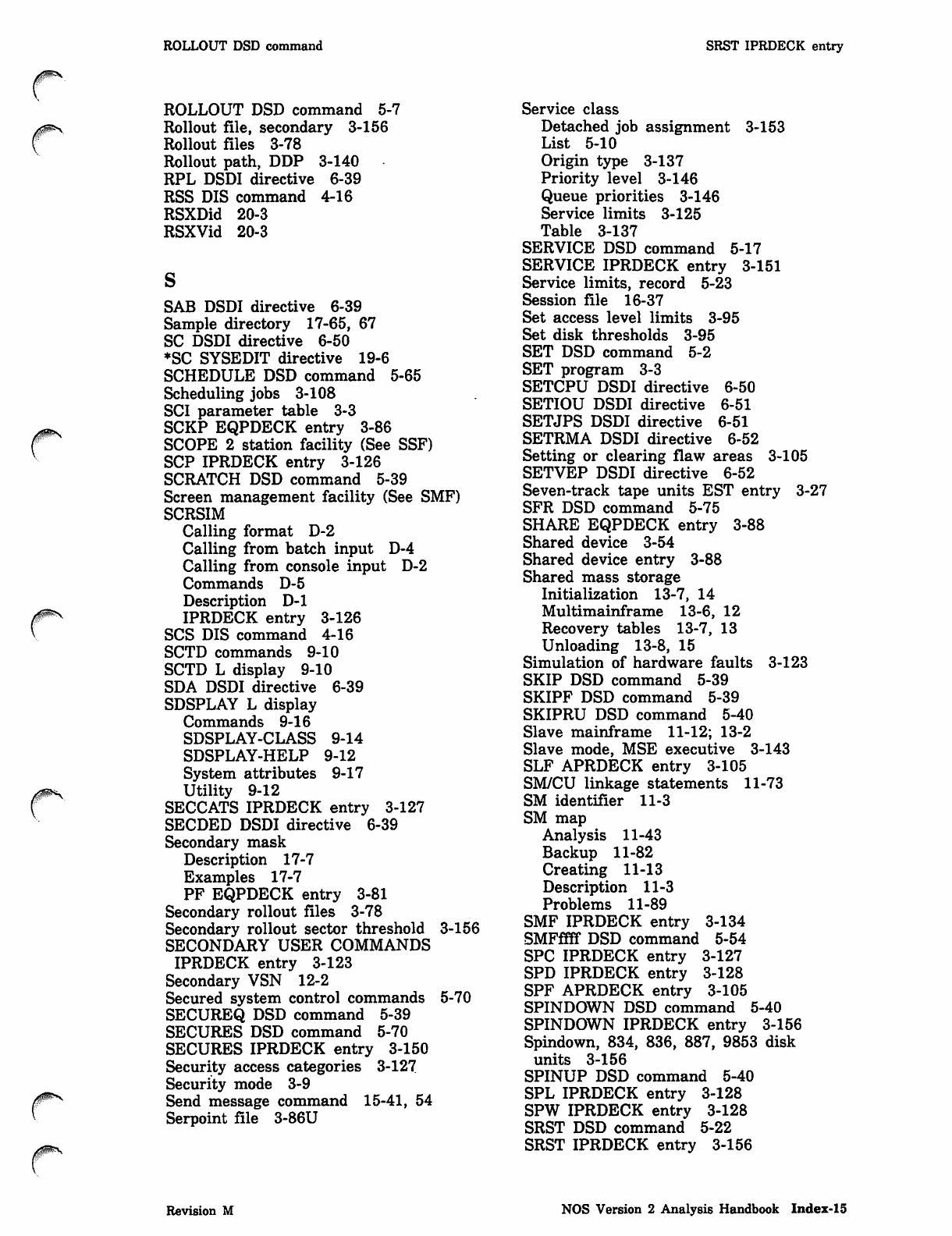
ROLLOUT DSD command SRST IPRDECK entry
yim^.
0ms
ROLLOUT DSD command 5-7
Rollout file, secondary 3-156
Rollout files 3-78
Rollout path, DDP 3-140
RPL DSDI directive 6-39
RSS DIS command 4-16
RSXDid 20-3
RSXVid 20-3
SAB DSDI directive 6-39
Sample directory 17-65, 67
SC DSDI directive 6-50
♦SC SYSEDIT directive 19-6
SCHEDULE DSD command 5-65
Scheduling jobs 3-108
SCI parameter table 3-3
SCKP EQPDECK entry 3-86
SCOPE 2 station facility (See SSF)
SCP IPRDECK entry 3-126
SCRATCH DSD command 5-39
Screen management facility (See SMF)
SCRSIM
Calling format D-2
Calling from batch input D-4
Calling from console input D-2
Commands D-5
Description D-l
IPRDECK entry 3-126
SCS DIS command 4-16
SCTD commands 9-10
SCTD L display 9-10
SDA DSDI directive 6-39
SDSPLAY L display
Commands 9-16
SDSPLAY-CLASS 9-14
SDSPLAY-HELP 9-12
System attributes 9-17
Utility 9-12
SECCATS IPRDECK entry 3-127
SECDED DSDI directive 6-39
Secondary mask
Description 17-7
Examples 17-7
PF EQPDECK entry 3-81
Secondary rollout files 3-78
Secondary rollout sector threshold 3-156
SECONDARY USER COMMANDS
IPRDECK entry 3-123
Secondary VSN 12-2
Secured system control commands 5-70
SECUREQ DSD command 5-39
SECURES DSD command 5-70
SECURES IPRDECK entry 3-150
Security access categories 3-127
Security mode 3-9
Send message command 15-41, 54
Serpoint file 3-86U
Service class
Detached job assignment 3-153
List 5-10
Origin type 3-137
Priority level 3-146
Queue priorities 3-146
Service limits 3-125
Table 3-137
SERVICE DSD command 5-17
SERVICE IPRDECK entry 3-151
Service limits, record 5-23
Session file 16-37
Set access level limits 3-95
Set disk thresholds 3-95
SET DSD command 5-2
SET program 3-3
SETCPU DSDI directive 6-50
SETIOU DSDI directive 6-51
SETJPS DSDI directive 6-51
SETRMA DSDI directive 6-52
Setting or clearing flaw areas 3-105
SETVEP DSDI directive 6-52
Seven-track tape units EST entry 3-27
SFR DSD command 5-75
SHARE EQPDECK entry 3-88
Shared device 3-54
Shared device entry 3-88
Shared mass storage
Initialization 13-7, 14
Multimainframe 13-6, 12
Recovery tables 13-7, 13
Unloading 13-8, 15
Simulation of hardware faults 3-123
SKIP DSD command 5-39
SKIPF DSD command 5-39
SKIPRU DSD command 5-40
Slave mainframe 11-12; 13-2
Slave mode, MSE executive 3-143
SLF APRDECK entry 3-105
SM/CU linkage statements 11-73
SM identifier 11-3
SM map
Analysis 11-43
Backup 11-82
Creating 11-13
Description 11-3
Problems 11-89
SMF IPRDECK entry 3-134
SMFffff DSD command 5-54
SPC IPRDECK entry 3-127
SPD IPRDECK entry 3-128
SPF APRDECK entry 3-105
SPINDOWN DSD command 5-40
SPINDOWN IPRDECK entry 3-156
Spindown, 834, 836, 887, 9853 disk
units 3-156
SPINUP DSD command 5-40
SPL IPRDECK entry 3-128
SPW IPRDECK entry 3-128
SRST DSD command 5-22
SRST IPRDECK entry 3-156
Revision M NOS Version 2 Analysis Handbook Index-15
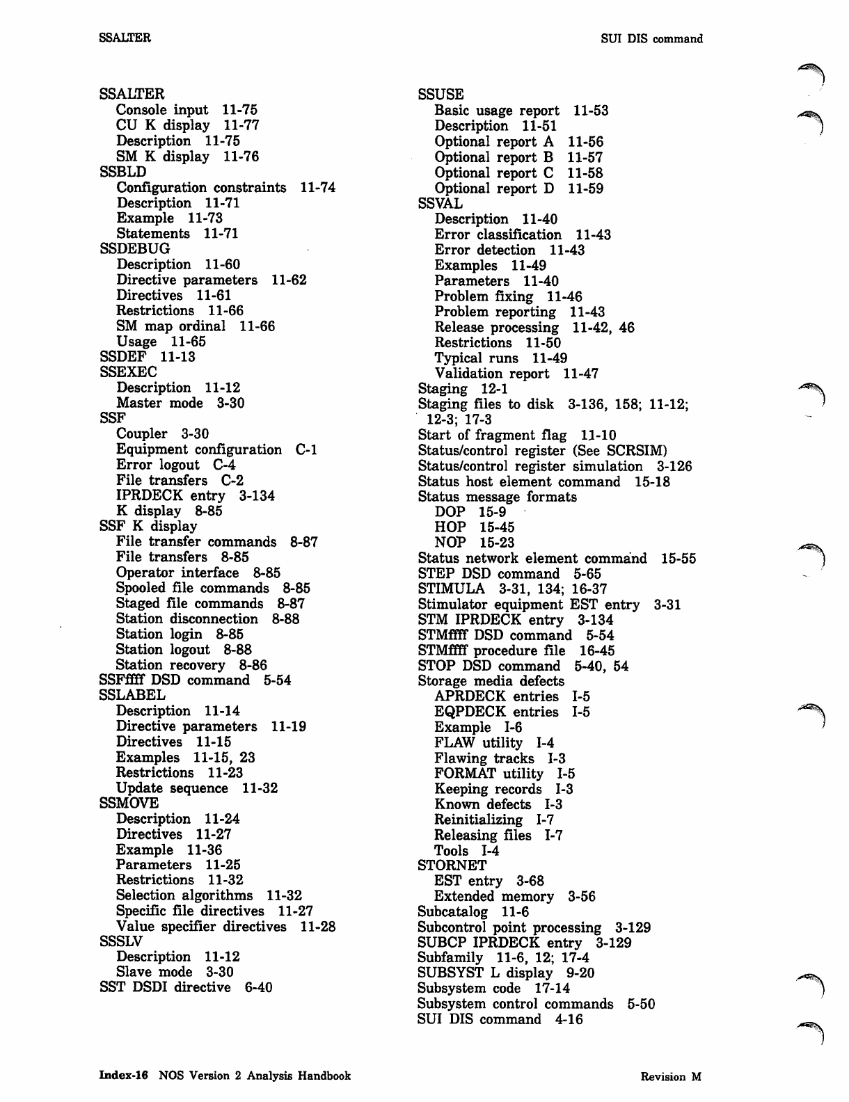
SSALTER SUI DIS command
SSALTER
Console input 11-75
CU K display 11-77
Description 11-75
SM K display 11-76
SSBLD
Configuration constraints 11-74
Description 11-71
Example 11-73
Statements 11-71
SSDEBUG
Description 11-60
Directive parameters 11-62
Directives 11-61
Restrictions 11-66
SM map ordinal 11-66
Usage 11-65
SSDEF 11-13
SSEXEC
Description 11-12
Master mode 3-30
SSF
Coupler 3-30
Equipment configuration C-l
Error logout C-4
File transfers C-2
IPRDECK entry 3-134
K display 8-85
SSF K display
File transfer commands 8-87
File transfers 8-85
Operator interface 8-85
Spooled file commands 8-85
Staged file commands 8-87
Station disconnection 8-88
Station login 8-85
Station logout 8-88
Station recovery 8-86
SSFffff DSD command 5-54
SSLABEL
Description 11-14
Directive parameters 11-19
Directives 11-15
Examples 11-15, 23
Restrictions 11 -23
Update sequence 11-32
SSMOVE
Description 11-24
Directives 11-27
Example 11-36
Parameters 11-25
Restrictions 11-32
Selection algorithms 11-32
Specific file directives 11-27
Value specifier directives 11-28
SSSLV
Description 11-12
Slave mode 3-30
SST DSDI directive 6-40
SSUSE
Basic usage report 11-53
Description 11-51
Optional report A 11-56
Optional report B 11-57
Optional report C 11-58
Optional report D 11-59
SSVAL
Description 11-40
Error classification 11-43
Error detection 11-43
Examples 11-49
Parameters 11-40
Problem fixing 11-46
Problem reporting 11-43
Release processing 11-42, 46
Restrictions 11-50
Typical runs 11-49
Validation report 11-47
Staging 12-1
Staging files to disk 3-136, 158; 11-12;
12-3; 17-3
Start of fragment flag 11-10
Status/control register (See SCRSIM)
Status/control register simulation 3-126
Status host element command 15-18
Status message formats
DOP 15-9
HOP 15-45
NOP 15-23
Status network element command 15-55
STEP DSD command 5-65
STIMULA 3-31, 134; 16-37
Stimulator equipment EST entry 3-31
STM IPRDECK entry 3-134
STMffff DSD command 5-54
STMffff procedure file 16-45
STOP DSD command 5-40, 54
Storage media defects
APRDECK entries 1-5
EQPDECK entries 1-5
Example 1-6
FLAW utility 1-4
Flawing tracks 1-3
FORMAT utility 1-5
Keeping records 1-3
Known defects 1-3
Reinitializing 1-7
Releasing files 1-7
Tools 1-4
STORNET
EST entry 3-68
Extended memory 3-56
Subcatalog 11-6
Subcontrol point processing 3-129
SUBCP IPRDECK entry 3-129
Subfamily 11-6, 12; 17-4
SUBSYST L display 9-20
Subsystem code 17-14
Subsystem control commands 5-50
SUI DIS command 4-16
Index-16 NOS Version 2 Analysis Handbook Revision M
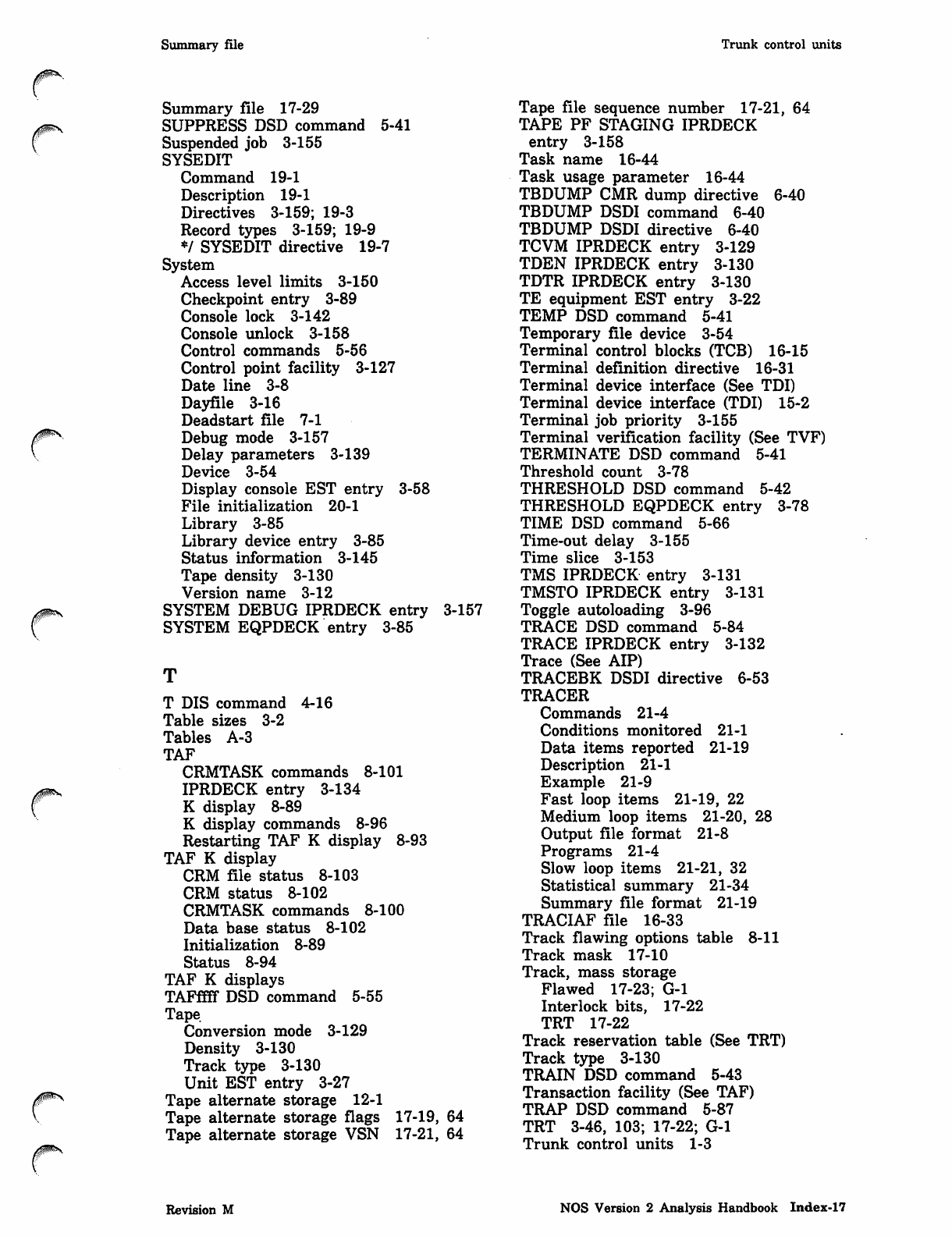
Summary file Trunk control units
Summary file 17-29
SUPPRESS DSD command 5-41
Suspended job 3-155
SYSEDIT
Command 19-1
Description 19-1
Directives 3-159; 19-3
Record types 3-159; 19-9
♦/ SYSEDIT directive 19-7
System
Access level limits 3-150
Checkpoint entry 3-89
Console lock 3-142
Console unlock 3-158
Control commands 5-56
Control point facility 3-127
Date line 3-8
Dayfile 3-16
Deadstart file 7-1
Debug mode 3-157
Delay parameters 3-139
Device 3-54
Display console EST entry 3-58
File initialization 20-1
Library 3-85
Library device entry 3-85
Status information 3-145
Tape density 3-130
Version name 3-12
SYSTEM DEBUG IPRDECK entry 3-157
SYSTEM EQPDECK entry 3-85
T DIS command 4-16
Table sizes 3-2
Tables A-3
TAF
CRMTASK commands 8-101
IPRDECK entry 3-134
K display 8-89
K display commands 8-96
Restarting TAF K display 8-93
TAF K display
CRM file status 8-103
CRM status 8-102
CRMTASK commands 8-100
Data base status 8-102
Initialization 8-89
Status 8-94
TAF K displays
TAFffff DSD command 5-55
Tape.
Conversion mode 3-129
Density 3-130
Track type 3-130
Unit EST entry 3-27
Tape alternate storage 12-1
Tape alternate storage flags 17-19, 64
Tape alternate storage VSN 17-21, 64
Tape file sequence number 17-21, 64
TAPE PF STAGING IPRDECK
entry 3-158
Task name 16-44
Task usage parameter 16-44
TBDUMP CMR dump directive 6-40
TBDUMP DSDI command 6-40
TBDUMP DSDI directive 6-40
TCVM IPRDECK entry 3-129
TDEN IPRDECK entry 3-130
TDTR IPRDECK entry 3-130
TE equipment EST entry 3-22
TEMP DSD command 5-41
Temporary file device 3-54
Terminal control blocks (TCB) 16-15
Terminal definition directive 16-31
Terminal device interface (See TDI)
Terminal device interface (TDI) 15-2
Terminal job priority 3-155
Terminal verification facility (See TVF)
TERMINATE DSD command 5-41
Threshold count 3-78
THRESHOLD DSD command 5-42
THRESHOLD EQPDECK entry 3-78
TIME DSD command 5-66
Time-out delay 3-155
Time slice 3-153
TMS IPRDECK entry 3-131
TMSTO IPRDECK entry 3-131
Toggle autoloading 3-96
TRACE DSD command 5-84
TRACE IPRDECK entry 3-132
Trace (See AIP)
TRACEBK DSDI directive 6-53
TRACER
Commands 21-4
Conditions monitored 21-1
Data items reported 21-19
Description 21-1
Example 21-9
Fast loop items 21-19, 22
Medium loop items 21-20, 28
Output file format 21-8
Programs 21-4
Slow loop items 21-21, 32
Statistical summary 21-34
Summary file format 21-19
TRACIAF file 16-33
Track flawing options table 8-11
Track mask 17-10
Track, mass storage
Flawed 17-23; G-l
Interlock bits, 17-22
TRT 17-22
Track reservation table (See TRT)
Track type 3-130
TRAIN DSD command 5-43
Transaction facility (See TAF)
TRAP DSD command 5-87
TRT 3-46, 103; 17-22; G-l
Trunk control units 1-3
Revision M NOS Version 2 Analysis Handbook Index-17
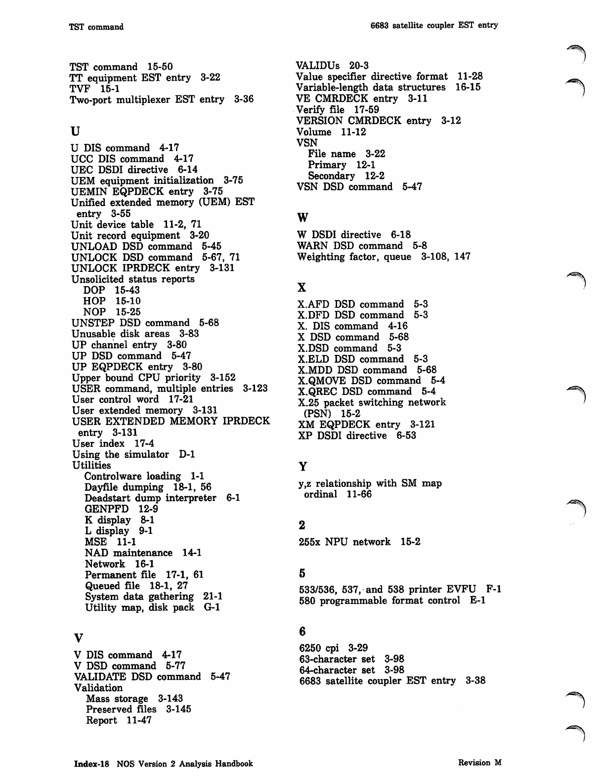
TST command 6683 satellite coupler EST entry
TST command 15-50
TT equipment EST entry 3-22
TVF 15-1
Two-port multiplexer EST entry
u
3-36
U DIS command 4-17
UCC DIS command 4-17
UEC DSDI directive 6-14
UEM equipment initialization 3-75
UEMIN EQPDECK entry 3-75
Unified extended memory (UEM) EST
entry 3-55
Unit device table 11-2, 71
Unit record equipment 3-20
UNLOAD DSD command 5-45
UNLOCK DSD command 5-67, 71
UNLOCK IPRDECK entry 3-131
Unsolicited status reports
DOP 15-43
HOP 15-10
NOP 15-25
UNSTEP DSD command 5-68
Unusable disk areas 3-83
UP channel entry 3-80
UP DSD command 5-47
UP EQPDECK entry 3-80
Upper bound CPU priority 3-152
USER command, multiple entries 3-123
User control word 17-21
User extended memory 3-131
USER EXTENDED MEMORY IPRDECK
entry 3-131
User index 17-4
Using the simulator D-l
Utilities
Controlware loading 1-1
Dayfile dumping 18-1, 56
Deadstart dump interpreter 6-1
GENPFD 12-9
K display 8-1
L display 9-1
MSE 11-1
NAD maintenance 14-1
Network 16-1
Permanent file 17-1, 61
Queued file 18-1, 27
System data gathering 21-1
Utility map, disk pack G-l
VALIDUs 20-3
Value specifier directive format 11-28
Variable-length data structures 16-15
VE CMRDECK entry 3-11
Verify file 17-59
VERSION CMRDECK entry 3-12
Volume 11-12
VSN
File name 3-22
Primary 12-1
Secondary 12-2
VSN DSD command 5-47
w
W DSDI directive 6-18
WARN DSD command 5-8
Weighting factor, queue 3-108, 147
X
5-3
5-3
5-3
5-68
X.AFD DSD command
X.DFD DSD command
X. DIS command 4-16
X DSD command 5-68
X.DSD command 5-3
X.ELD DSD command
X.MDD DSD command
X.QMOVE DSD command 5-4
X.QREC DSD command 5-4
X.25 packet switching network
(PSN) 15-2
XM EQPDECK entry 3-121
XP DSDI directive 6-53
y,z relationship with SM map
ordinal 11-66
255x NPU network 15-2
533/536, 537, and 538 printer EVFU F-l
580 programmable format control E-l
V
V DIS command 4-17
V DSD command 5-77
VALIDATE DSD command
Validation
Mass storage 3-143
Preserved files 3-145
Report 11-47
5-47
6250 cpi 3-29
63-character set 3-98
64-character set 3-98
6683 satellite coupler EST entry 3-38
Index-18 NOS Version 2 Analysis Handbook Revision M
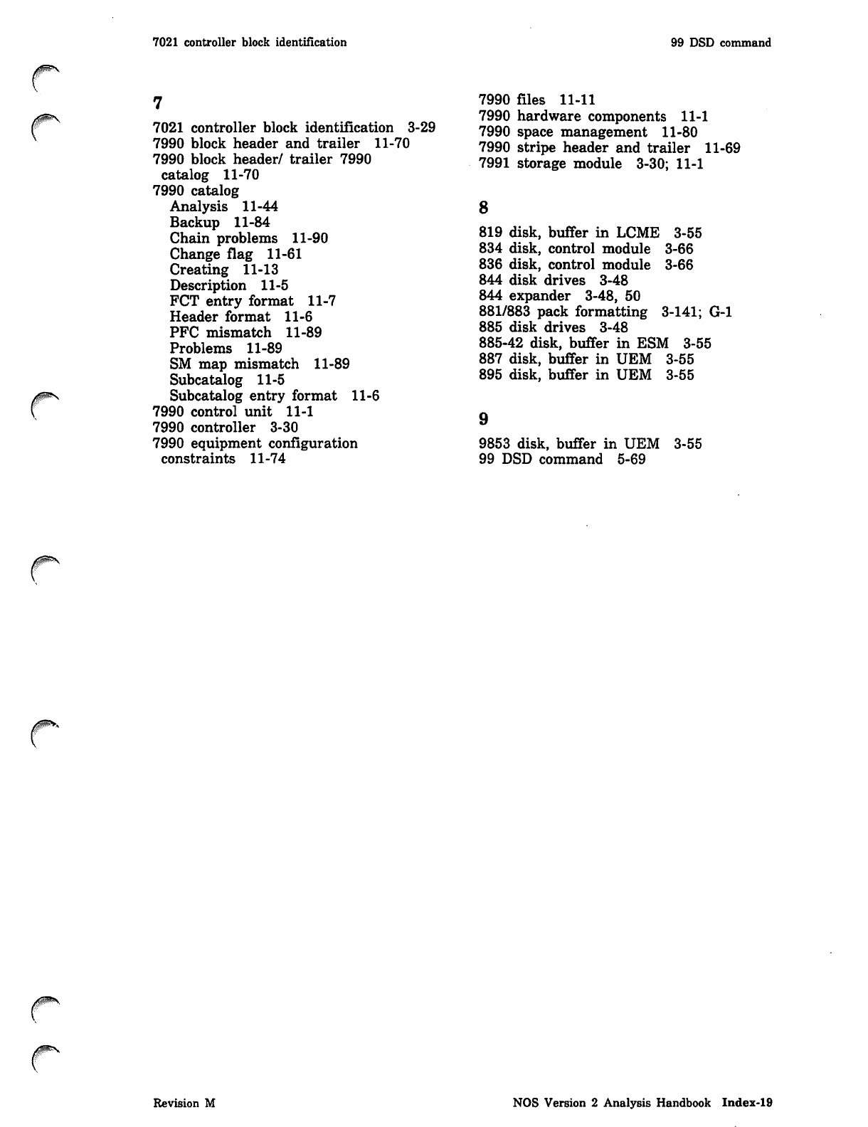
7021 controller block identification
^p*v
7021 controller block identification 3-29
7990 block header and trailer 11-70
7990 block header/ trailer 7990
catalog 11-70
7990 catalog
Analysis 11-44
Backup 11-84
Chain problems 11-90
Change flag 11-61
Creating 11-13
Description 11-5
FCT entry format 11-7
Header format 11-6
PFC mismatch 11-89
Problems 11-89
SM map mismatch 11-89
Subcatalog 11-5
Subcatalog entry format 11-6
7990 control unit 11-1
7990 controller 3-30
7990 equipment configuration
constraints 11-74
99 DSD command
7990 files 11-11
7990 hardware components 11-1
7990 space management 11-80
7990 stripe header and trailer 11-69
7991 storage module 3-30; 11-1
8
819 disk, buffer in LCME 3-55
834 disk, control module 3-66
836 disk, control module 3-66
844 disk drives 3-48
844 expander 3-48, 50
881/883 pack formatting 3-141; G-l
885 disk drives 3-48
885-42 disk, buffer in ESM 3-55
887 disk, buffer in UEM 3-55
895 disk, buffer in UEM 3-55
9853 disk, buffer in UEM
99 DSD command 5-69 3-55
Revision M NOS Version 2 Analysis Handbook Index-19

f*%
Comments (continued from other side)
0m*
Please fold on dotted line;
seal edges with tape only. FOLD
rFOLD FOLD
NO POSTAGE
NECESSARY
IF MAILED
IN THE
UNITED STATES
BUSINESS REPLY MAIL
First-Class Mail Permit No. 8241 Minneapolis, MN
POSTAGE WILL BE PAID BY ADDRESSEE
CONTROL DATA
Technical Publications
ARH219
4201 N. Lexington Avenue
Arden Hills, MN 55126-9983
l.l.l..l,l„..ll,.l,l,ll,.l,l„l,l„l„l„,ll,„i.ll
NOS Version 2 Analysis Handbook 60459300 M
We would like your comments on this manual to help us improve it. Please take a few minutes to fill out
this form.
Who are you? How do you use this manual?
D Manager □ As an overview
D Systems analyst or programmer □ To learn the product or system
D Applications programmer □ For comprehensive reference
D Operator □ For quick look-up
D O t h e r □ Other
What programming languages do you use?
How do you like this manual? Answer the questions that apply.
Does it tell you what you need to know about the topic?
Is the technical information accurate?
Is it easy to understand?
Is the order of topics logical?
Can you easily find what you want?
Are there enough examples?
Are the examples helpful? (D Too simple? D Too complex?)
Do the illustrations help you?
Is the manual easy to read (print size, page layout, and so on)?
Do you use this manual frequently?
Comments? If applicable, note page and paragraph. Use other side if needed.
Yes Somewhat No
D D D
D□a
D D D
D D a
D□ □
□D□
D D D
D□ □
D D D
D D D
Check here if you want a reply: □
Name Uompany
Address Date
Phone '
Please send program listing and output if applicable to your comment.
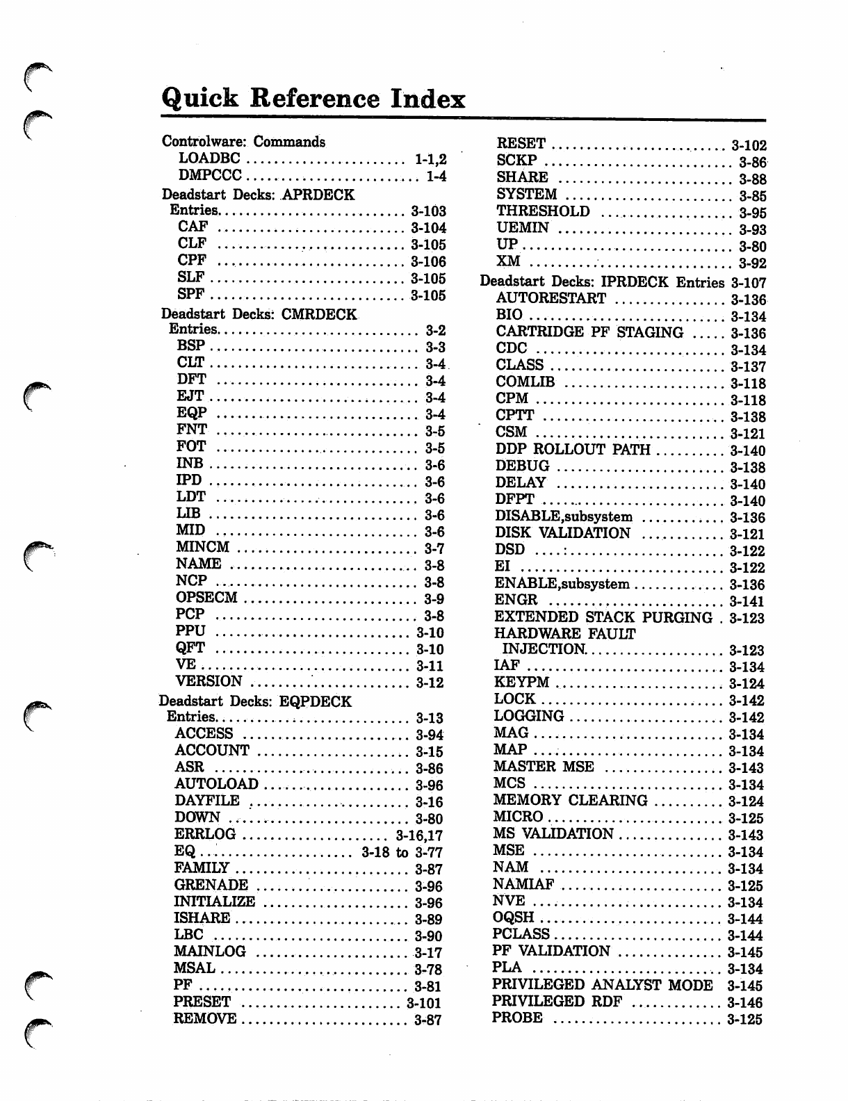
{^
#^
#^'
Quick Reference Index
Controlware: Commands
LOADBC 1-1,2
DMPCCC 1-4
Deadstart Decks: APRDECK
Entries. 3-103
CAF 3-104
CLF 3-105
CPF 3-106
SLF 3-105
SPF 3-105
Deadstart Decks: CMRDECK
Entries 3-2
B S P . 3 - 3
C L T . . . 3 - 4
DFT ...3-4
EJT 3-4
EQP 3-4
FNT 3-5
FOT 3-5
INB ..3-6
IPD 3-6
LDT •.. 3-6
LIB 3-6
MID 3-6
MINCM 3-7
NAME .. 3-8
NCP .., 3-8
OPSECM 3-9
PCP .3-8
PPU 3-10
QFT 3-10
V E . 3 - 1 1
VERSION .- .'.. 3-12
Deadstart Decks: EQPDECK
Entries..... , 3-13
ACCESS 3-94
ACCOUNT 3-15
ASR 3-86
AUTOLOAD 3-96
DAYFILE 3-16
DOWN 3-80
ERRLOG 3-16,17
EQ..: 3-18 to 3-77
FAMILY 3-87
GRENADE 3-96
INITIALIZE 3-96
ISHARE 3-89
LBC 3-90
MAINLOG 3-17
MSAL 3-78
PF 3-81
PRESET ... 3-101
REMOVE 3-87
RESET
SCKP
SHARE
SYSTEM ....
THRESHOLD
UEMIN
UP
XM
Deadstart Decks: IPRDECK Entries
AUTORESTART
BIO
CARTRIDGE PF STAGING
CDC
CLASS
COMLIB
CPM
CPTT ,.
CSM
DDP ROLLOUT PATH
DEBUG
DELAY
DFPT
DISABLE,subsystem
DISK VALIDATION
DSD ....:
EI
ENABLE,subsystem
ENGR
EXTENDED STACK PURGING .
HARDWARE FAULT
INJECTION.
IAF
KEYPM
LOCK
LOGGING
MAG....
MAP
MASTER MSE
MCS
MEMORY CLEARING
MICRO
MS VAUDATION
MSE
NAM
NAMIAF
NVE
OQSH
PCLASS
PF VALIDATION
PLA
PRIVILEGED ANALYST MODE
PRIVILEGED RDF
PROBE
3-102
. 3-86
. 3-88
. 3-85
. 3-95
. 3-93
. 3-80
. 3-92
3-107
3-136
134
136
134
137
118
118
3-138
3-121
3-140
3-138
3-140
3-140
3-136
3-121
3-122
3-122
3-136
3-141
3-123
3-123
3-134
3-124
142
142
134
134
143
3-134
3-124
3-125
3-143
3-134
3-134
3-125
3-134
3-144
3-144
3-145
3-134
3-145
3-146
3-125
QUEUE 3-146
RBF 3-134
RDF 3-134
REMOVABLE PACKS 3-148
RESIDENT RDF 3-148
RHF .. .....3-134
SCP .* 3-126
SCRSIM .. 3-126
SECCATS 3-127
SECONDARY USER
COMMANDS. 3-149
SECURES 3-150
SERVICE 3-150
SMF 3-134
SPC 3-127
SPD 3-128
SPINDOWN 3-156
SPL. 3-128
SPW 3-128
SRST 3-156
SSF ..3-134
S T M ■.. 3-134
SUBCP .. 3-129
SYSTEM DEBUG .............. 3-157
TAF 3-134
TAPE PF STAGING 3-158
TCVM , 3-129
TDEN... ...3-130
T D T R . ■ 3-130
TMS 3-131
TMSTO .. 3-131
TRACE 3-132
UNLOCK ...'.- 3-158
USER EXTENDED MEMORY .. 3-158
Deadstart Decks: LIBDECK 3-159
*AD .. 3-159
*CM ... 3-159
*FL 3-159
*MS 3-159
*PROC 3-160
*SC 3-160
*/ .. ..... .............. 3-160
DIS Commands
BEGIN... 4-14
BKP .. 4-14
BKPA 4-14
CEF 4-14
DCP 4-14
D D F . 4 - 1 4
DIS 4-14
Display Selection 4-13
DROP.... 4-14
ELS........ 4-14
ENAi . 4-14
ENBi ,.■ 4-14
ENEM 4-14
ENFL 4^14
ENFLE ....4-15
ENP 4-15
ENPR 4-15
ENS 4-15
ENTER 4-15
ENTL 4-15
ENXi 4-15
ERR 4-15
GO 4-15
HOLD 4-15
M .....4-15
Memory Entry 4-18,19
N 4 - 1 5
OFFSWs 4-16
ONSWs 4-16
026 ... 4-16
PP Call 4-20
RCP ...4-16
RCS 4-16
RNS 4-16
ROLLOUT 4-16
RSS 4-16
SCS 4-16
SET..... 4-13
SUI 4-16
T 4 - 1 6
U 4 - 1 7
UCC 4-17
V 4 - 1 7
X 4 - 1 7
*.,...... 4-17
DSD Commands
ACN 5-74
ASSIGN 5-24
A U T O . 5 - 5 6
BIO 5-50
BKP 5-76
BKSP ........,.,........; 5-24
BKSPF.... , 5-24
BKSPRU .• 5-25
C D C f f f f 5 - 5 0
CFO 5-9
CFR 5-75
CHECK POINT SYSTEM 5-56,57
CKP 5-4
CLASS 5-10
COMMENT 5-9
CONTINUE 5-25
CPB 5-80,81
CPTT .....5-11
CPUMTR breakpoint.... .. 5-80
DATE ........ -.-. 5-57
DCH 5-74
DCN 5-74
DEBUG 5-58
f**
00ms
Debugging .. 5-84
D E L A Y 5 - 1 1
DIAL ........ 5-8
DIS 5-58
DISABLE 5-50 to 5-64
DOWN 5-25,26
D R O P . . , 5 . 5
ENABLE 5-59 to 5-64
END 5-27
ENPR 5-5
ENQP 5-5
FCN 5-74
FORM . 5-27
G O 5 - 9
IAFffff 5-50,51
IAN ..5-74
ID 5-27
I D L E . . . . . . 5 - 2 8 , 2 9 , 5 2 , 6 4
IDLEFAMILY 5-29
INITIALIZE 5-30 to 5-33
K 5 - 6 4
KILL 5-6
L. 5.64
LDC 5-74
LOAD 5-32
LOCK 5-64
M A G f f f f 5 - 5 2
MAINTENANCE 5-65
M A P f f f f 5 - 5 2
MCH 5-74
M C S f f f f 5 - 5 2
Memory Entry 5-57,58
MOUNT 5-33
MSAL 5-34
M S E f f f f 5 - 5 3
NAMffff.. 5-53
NEXTREEL 5-35
OAN 5-74
OFF 5-36
OFFSW 5-9
ON 5-37
ONSW 5-9
OQSH 5-70
OVERRIDE 5-6
PAUSE 5-9
PCLASS .. 5-13
P L A f f f f 5 - 5 3
PP 5-76
PP breakpoint .... 5-75
PRIVILEGED ANALYST MODE . 5-61
PRSIZE 5-37
QUEUE 5-14
R B F f f f f 5 - 5 3
RDFffff.,... 5-53
RELEASE 5-70
REPEAT 5-38
REPRINT 5-38
REPUNCH 5-38
RERUN 5-7
RETRY 5-38
R H F f f f f 5 - 5 4
ROLLIN 5-7
ROLLOUT ...5-7
SCRATCH 5-39
SCHEDULE 5-65
SECUREQ ,... 5-39
SECURES 5-70
SERVICE 5-17
SET ....5-2
SFR 5-75
SKIP . 5-39
SKIPF 5-39
SKIPRU 5-40
S M F f f f f 5 - 5 4
SPINDOWN 5-40
SPINUP 5-40
SRST 5-22
S S F f f f f 5 - 5 4
STEP 5-65,66
STMffff .5-54
STOP 5-40,54
SUPPRESS 5-41
T A F f f f f 5 - 5 5
TEMP 5-41
TERMINATE 5-41
THRESHOLD 5-42,43
TIME 5-66
TRACE ..-. 5-84 to 5-86
TRAIN 5-43,44
TRAP 5-87,88
UNLOAD 5-45,46
UNLOCK -.. 5-67,68,71
UNSTEP 5-68
UP 5-47
V 5 - 7 7
VALIDATE 5-47
VSN 5-47 to 5-49
W A R N - . 5 - 8
X 5 - 6 8
X.AFD 5-3
X.DFD ...: 5-3
X.ELD 5-3
X.MDD 5-68
X.QMOVE 5-4
X.QREC 5-4
x y 5 - 2
99 5-69
DSDI Input Directives
ACCOUNT 6-26
ALLMEM .6-12
AP 6-19
BATCHIO 6-41
BCDUMP 6-54
BIO 6-41
C 6-15,57
CBT 6-27
CCT .6-27
CM 6-12
CP 6-28,58
CPO .6-30
CT .6-30
D 6-16,59
DAYFILE 6-30
DB 6-30
DBW 6-31
DDB 6-31
DISPOSE 6-10,56
DP 6-31
E 6 - 1 6
EC 6-13
EICB 6-31
E J . 6 - 8
EJOFF 6-8
EJON 6-8
EJT 6-31
EPB 6-32
ERRLOG 6-32
EST........ 6-32
FMFREG 6-46
FNT 6-32
FOT 6-32
H A T 6 - 3 3
I 6 - 1 7
IAF 6-42
IOUCR 6-46
IOUMR 6-46
JC 6-33
LC 6-33
LDIS... 6-34
LIDT... 6-34
LPVA 6-47
MAG... 6-44
MAGNET 6-44
MAINLOG 6-34
MCT .... .., 6-34
MEMMR 6-47
MPP 6-20
MST 6-35
MTR 6-35
MTRQUEUE ... 6-36
ODIS. ,.. 6-36
OUTPUT 6-10,56
P 6 - 2 0
PCP ...6-36
PD...... 6-8
PF 6-21
PLD 6-37
PMS 6-21
PO 6-22
PP 6-37,60
PROBE 6-37
PROCA 6-48
PROCW 6-48
PROMR 6-48
PROPM . 6-49
PRORF f>49
PROSM 6-49
PROXP ...-. 6-50
PST.... 6-37
PUT 6-38
PX 6-22
Q 6-23,61
QF 6-23
QFT 6-38
QOA 6-24,62
QOD 6-24,62
QXA 6-25,62
QXD 6-25,62
RA 6-13
RAC 6-14
RCL 6-38
READ 6-11
REWIND 6-11
RHF 6-45
RPL 6-39
S C : 6 - 5 0
SAB 6-39
SDA .., 6-39
SECDED 6-39
SETCPU 6-50
SETIOU 6-51
SETJPS 6-51
SETRMA 6-52
SETVEP 6-52
SST 6-40
TBDUMP 6-40
TRACEBK 6-53
UEC 6-14
W... 6-18
XP 6-53
* . 6 - 9
INSTALL: Command
INSTALL... 7-1
K-Display Commands
CLASS 8-47,48
CRMTASK Commands ... 8-94 to 8-97
DB. 8-32
DE 8-33
DISABLE 8-47,49
DU 8-33
ENABLE 8-47,49
FL 8-34
HELP 8-47,50
IDLE 8-47,50
INCLUDE 8-47,50
INITIALIZE 8-8
**%
^
f*
f*
K,CMS 8-9
K.DIS,CRMTASK 8-100
K,MSE 8-25
K,NAM 8-27
K,RBF 8-72
K.RERUN....,....... 8-11
K,RHF 8-78
K,SSF 8-85
K,TAF 8-89
LB .... 8-34
LE 8-35
LR ...... 8-35
MREC Commands 8-20
MSE Commands 8-25
NAM Mode Commands 8-30,31
NAM Mode Maintenance
Commands 8-32 to 8-40
QTF Commands 8-47 to 8-61
Reconfiguration Commands 8-66
REDEFINE 8-61
RHF Commands 8-78 to 8-84
RS 8-36
SCHED ,. 8-47,52
SSF Commands 8-85 to 8-86
ST 8-37
STATUS 8-47,53
TAF Commands 8-89 to 8-99
X.FLAW 8-4
X.MREC 8-16,20
L-Display Commands
FOTD 9-1,2
LDISopt 9-1
LIDOU 9-1,3
QDSPLAY 9-1,6
SCTD 9-1,10
SDSPLAY 9-1,12,16
SUBSYST 9-1,20
LID/RHF Configuration Files:
Commands
LISTLID 10-7
QTF 10-23
RCFGEN 10-9
X.CLDT '.. 10-6
LID/RHF Configuration Files: LID
Configuration Statements
NLID 10-3
NPID 10-2
LID/RHF Configuration Files: RHF
Configuration Statements
APPL 10-11,13
CHARGE 10-11,19
DEBUG 10-11,18
LNAD 10-11,16
LNDR ... 10-11,13
NPID 10-11,15
PATH 10-11,15
RNAD 10-11,18
Mass Storage Extended Subsystem
(MSE): Commands
SSALTER 11-2,75
SSBLD n-2,71
SSDEBUG H-2,60
SSDEF 11-2,13
SSLABEL 11-2,14
SSMOVE 11-2,24
SSUSE 11-2,51
SSVAL , 11-2,40
Tape Alternate Storage: Commands
MAGNET 12-8
GENPFD ,. 12-9
NAD Maintenance: Commands
DMPNAD 14-1
MHF 14-3
NETWORK OPERATIONS:
Commands
ALERT 15-26,62
CFO 15-6
CONTROL 15-27,62
DISABLE ., 15-15,29 to 31,61,62
DUMP 15-40,62
ENABLE 15-16,33 to 36,61,62
FILE 15-12,62
GO 15-37,62
HISTORY 15-52,61,62
IDLE 15-16,61
INFO 15-48,62
LOAD 15-38,39,62
NAM 15-5
NAMNOGO 15-6
NOFILE . 15-11,51
REPORT 15-53,62
SEND 15-41,54,62
STATUS 15-12,13,18 to 20,55 to
58,61,62
TST. 15-50,62
NETWORK Commands
COLLECT 16-6
DEMUX 16-52
IAFEX 16-32
LFG 16-9
LISTPPM 16-31
NAMI 16-2
NDA .. 16-12
STIMULA 16-37
PERMANENT FILE Commands
FAMILY 17-25
PFATC 17-1,66
PFCAT 17-1,66
PFCOPY 17-1,72
PFDUMP , 17-1,72
PFLOAD 17-1,77
PFREL 17-1,92
QUEUE/DAYFILE Commands
AFD 18-56
DFD 18-56
DFLIST .......... 18-1,27
DFTERM 18-1,27
ELD 18-56
GETLOG ,........ 18-56
LDLIST 18-1,31
MAINLOG 18-56
QALTER 18-1,31
QDUMP 18-1,37
QFTLIST 18-1,41
QLIST 18-1,41
QLOAD 18-1,42
QMOVE 18-1,45
QREC 18-1,50
SYSEDIT Directives
*AD .... 19-4,5
*CM 19-3
*DELETE 19-7
♦FILE 19-8
*FL 19-6
♦IGNORE 19-8
*MS 19-3
♦PPSYN 19-8
♦PROC 19-5
*SC 19-6
*/....., 19-7
System File Initialization:
Commands
ISF 20-1
TRACER/PROBE Utilities:
Commands
ACPD 21-3,4
CPD ., 21-3
ENDCPD 21-3,5
ICPD 21-3,6
PROBE 21-37
