PI CAT132E Precision Positioning And Motion Control
User Manual: Pdf Industry-Compliant, Motorized, Precision Positioning Systems
Open the PDF directly: View PDF ![]() .
.
Page Count: 298 [warning: Documents this large are best viewed by clicking the View PDF Link!]

WWW.PI.WS
AIR BEARING
REPEATABILITY
BALL SCREW
MICRO
POSITIONING
VOICE COIL
LINEAR MOTOR
ACCURACY
DIRECT DRIVE
ENGINEERED SYSTEMS
NANOPOSITIONING
PRECISION POSITIONING
AND MOTION CONTROL
HIGH DYNAMICS
PIMAG®
PIGLIDE

WWW.PI.WS
2
Precision Positioning and Motion Control
Product Finder Online – What is the easiest way for you to find the best positioning solution?
The printed catalog is a major showcase for PI and, as well as presenting the entire product
range, it also acts as a reference for all of our motion solutions. However, to take advantage
of the latest products and developments, we recommend using the product finder on the PI
website www.pi.ws.
How to use the product finder:
Select the product type specified by the axes of motion required. Selection of more criteria
expands or shortens the list of results. Select more than one filter at a time, for example, to
find positioning stages designed for higher load capacity, too.
INTRODUCTION
Markets and Applications ............................................................................................ 04
Motorized Standard Products Overview ...................................................................... 10
Technological Depth for Optimized Products .............................................................. 12
Custom Examples Picture Wall ................................................................................... 15
The PI Group – A Strong Partner for Industry and Research ....................................... 17
The PI Group Milestones ............................................................................................. 18
Expert Consulting ........................................................................................................ 20
Engineering Design Expertise and Customization ....................................................... 21
Production Capabilities ............................................................................................... 22
Vacuum Know-how ..................................................................................................... 23
From 1-off to Series: OEM Users Benefit From Maximum Flexibility ........................... 24
Global Service and After-Sales .................................................................................... 25
Preferred Solutions for High-Precision Automation Tasks .......................................... 26

MOTION | POSITIONING
3
More information, step-files and downloads are available from our website www.pi.ws.
All data subject to change without notice, ©PI 2018.
PRODUCTS
XY Stages ........................................................................................................................................................................... 138
XY Stages with Mechanical Bearings .......................................................................... 140
PIglide XY Stages with Air Bearings ............................................................................ 158
Translation Stages .............................................................................................................................................................. 28
Precision Linear Stages ................................................................................................ 30
High-Precision Linear Stages ....................................................................................... 72
PIglide Linear Air Bearing Stages ................................................................................. 112
Z Stages ....................................................................................................................... 126
Linear Actuators .................................................................................................................................................................. 200
Voice Coil Actuators .................................................................................................... 202
Screw-Drive Precision Actuators ................................................................................. 216
High-Load Screw-Drive Actuators ............................................................................... 226
Motion Control .................................................................................................................................................................... 232
Industrial motion control ............................................................................................. 234
Modular Multi-Channel Piezo Controllers .................................................................... 250
Stepper Motor Controllers ........................................................................................... 252
DC Motor Controllers .................................................................................................. 254
Voice Coil Controllers .................................................................................................. 258
Gantry Systems .................................................................................................................................................................. 260
Throughput, Precision and Reliability ......................................................................... 262
Terms and Technology Glossary ......................................................................................................................................... 290
Components & Accessories ................................................................................................................................................ 264
Air Bearings ................................................................................................................. 266
Accessories for Air Bearings and Stages ..................................................................... 280
Adapter Brackets for Multi-Axis Combinations ........................................................... 286
Rotation Stages .................................................................................................................................................................. 162
Rotation Stages ........................................................................................................... 164
Rotation Stages with Torque Motor and Air Bearing .................................................. 184
Goniometer Stages ..................................................................................................... 192
Terms and Technology
Glossary
Components &
Accessories Gantry Systems Motion Control Linear Actuators Rotation Stages XY Stages Translation Stages Introduction
WWW.PI.WS
4
Markets and Applications
SEMICONDUCTOR PRODUCTION AND INSPECTION
The automation of process steps in production and inspection is steadily on the increase. At the same time, the requirements to
accuracy required in motion and positioning are growing. Today, in many industrial areas accuracy levels are needed as they were
needed just a few years ago in research institutions. PI with its linear stages, rotation stages, and lifting stages, as well as more
complex multi-axis kinematics, offers excellent solutions for industrial applications in many growing markets and even for very
general automation tasks with challenging specifications.
The requirements to the straightness and flatness, and the precision are particu-
larly high in the production and inspection of semiconductors or circuit boards.
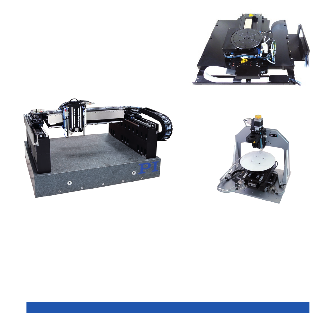
High dynamics of the motion axis are required for an optimized throughput. In this
case, a standard A-311 stage with a 200 mm × 200 mm travel range in XY carries a
customized rotation stage. All stages have air bearings to warrant the best flatness
and direct drives for precision and high dynamics positioning. In addition, it is
possible to hold a stable position
Wafer inspection system with integrated linear
motor axes for fast precision XY scanning.
Stepper motor axis for fine vertical position of
the inspection equipment
The semiconductor industry often requires very specific solutions, e.g., for wire
or ball bonders. PI's Gantry systems are an ideal basis for customized adaptations.
The strokes and the stacking height can be varied almost arbitrarily, the configura-
tion of the motors provides extremely high accelerations of up to 5 g and this
ensures the highest productivity in the application. Control features of ACS motion
controllers such as “Input Shaping” help to build a stable system which actively
suppresses possible vibrations
MOTION | POSITIONING
5
PHOTONICS PACKAGING AND OPTICAL ALIGNMENT
During production and inspection of components with optical data transmission, it is important to align fibers or fiber arrays for
optimum connection with the highest possible accuracy. Position tolerances way under 50 nm are usual and multi-channel inputs
and outputs require simultaneous alignment in several axes.
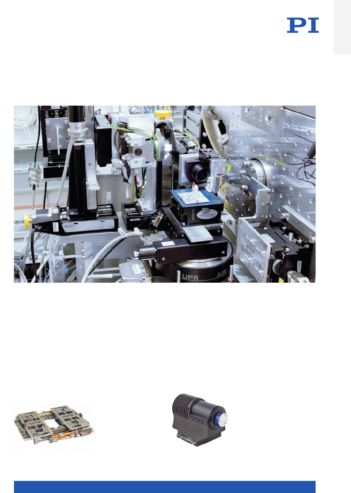
In photonics, automated alignment is the key to high throughput
and outstanding quality. The basis of this optical alignment system is
a very stiff XYZ set-up consisting of three motorized linear stages
and a P-616 NanoCube® piezo nanopositioner. The low overall height
simplifies integration in limited installation space. The motorized
drives make longer travel ranges possible and at the same time, the
NanoCube® nanopositioner ensures fast scanning motion and dynamic
compensation of drift effects. Flexure guides and all-ceramic insulated
PICMA® actuators guarantee a long lifetime. Because all drives are
equipped with position sensors, it is possible for example, to reliably
prevent collisions with expensive silicon wafers
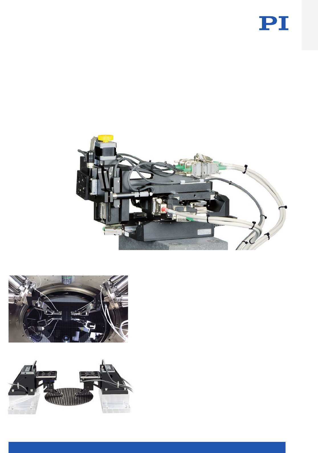
18-axis double alignment system provides fast NxM alignment
of SiP devices in wafer probers. Cascade Microtech’s pioneering
CM300xi photonics-enabled engineering wafer probe station
integrates PI’s parallel-kinematic Fast Multichannel Photonics
Alignment systems for high throughput, wafer-safe, nano-
precision optical probing of on-wafer Silicon Photonics devices.
(Image: Cascade Microtech, a FormFactor company)
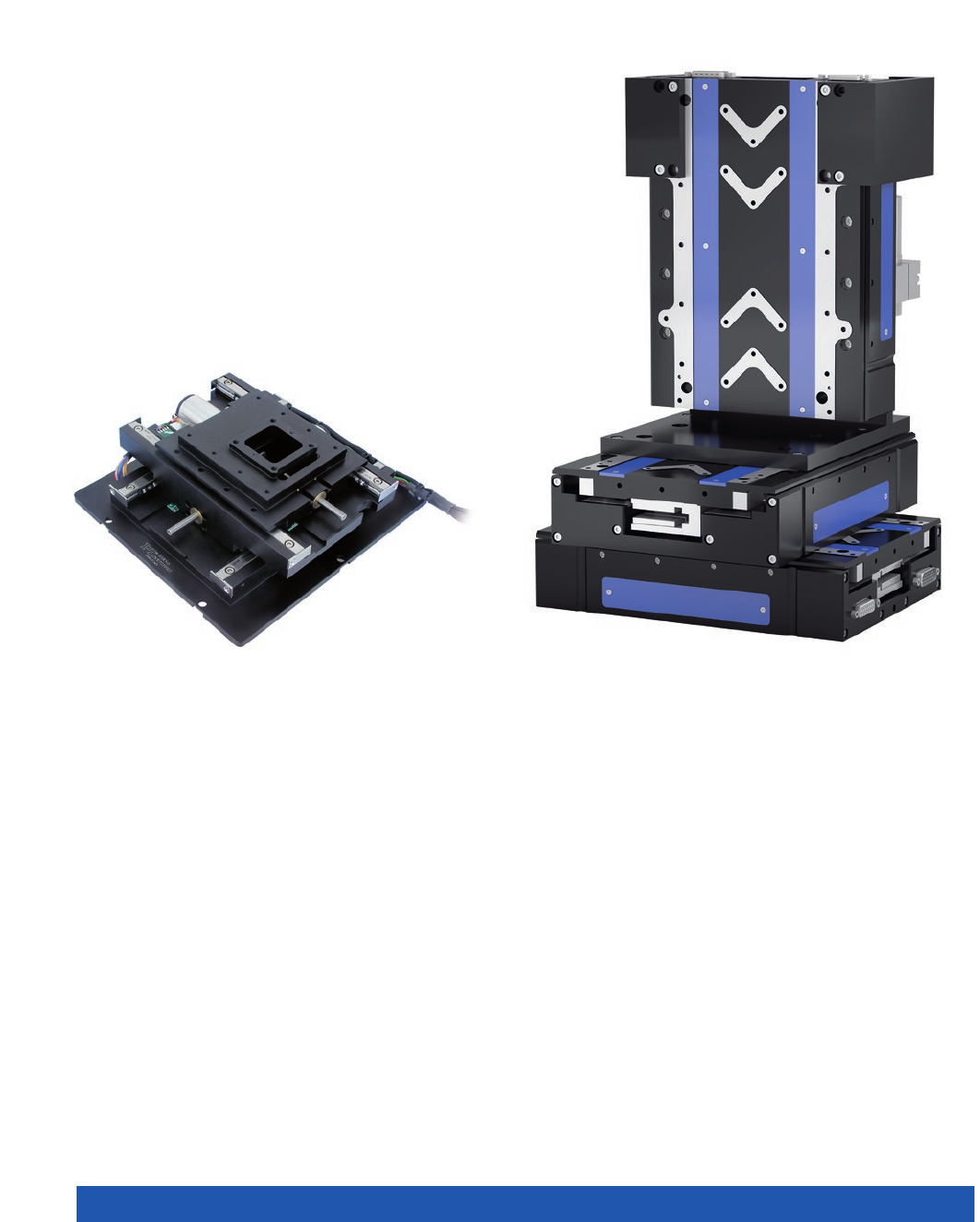
In this multi-axis system for
wafer inspection and photonics
alignment, high speed linear motor
stages are used for the long xy stroke,
while mechanical stages with stepper
motors and screw drives are used for the
other degrees of freedom that do not require
too high dynamics
Introduction
WWW.PI.WS
6
Markets and Applications
INDUSTRIAL MANUFACTURING
The field of industrial manufacturing and assembly offers the widest range of applications for the PI micropositioning stages. In
many applications the precision requirements keep growing for industrial application.
For example, digital printing becomes more and more common. The accuracy of the separate dots needs to be better than 20 µm
to be recognized as equidistant by the human eye. This requires motion technology providing an accuracy typically 10 times higher
meaning 2 µm, as well as motion with constant speed, good straightness and flatness.
Another example is force-controlled testing of a touch screen, a keyboard or electronic car keys, as well as the control of force
with which small parts are being assembled. Here, PI offers advanced solutions for those markets using its proprietary voice coil
and force sensor technologies.
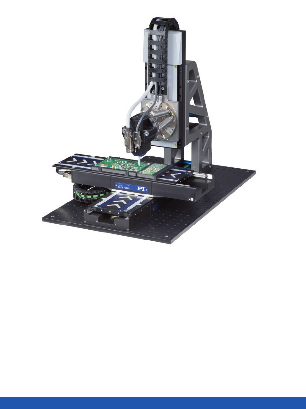
Automated testing procedures ensure
quality, e.g., in the production process
of printed circuit boards (PCBs). Thereby,
the precise control of the forces acting
on the sensitive boards as well as the fast
capturing and interpretation of measure-
ment data are extremely important
MOTION | POSITIONING
7
LASER MATERIAL PROCESSING
Laser cutting for example, often requires lowest tracking errors while following the
arbitrary path of the customer’s workpiece. This means very dynamic multi-axis motion
that is ideally realized by using linear motor solutions which combine dynamics and
accuracy. An additional vertical motion is typically realized using a ball screw stage.
For improved dynamics in the Z-direction, a linear motor axis can be equipped with a
mechanical, magnetic or pneumatic weight balance. These applications can be served
with standard linear stages with a debris protection or with fully customized solutions.
Building Highly Productive Laser Systems
ACS Motion Control, as part of the PI group, allows to supply highly sophisticated
Motion Controller and Universal Drive Modules for the control of laser processing
applications. Control of the laser power and the triggering of the laser is done by the
LCMV2 Laser Control Module. A dedicated software to create a custom specific Human
Machine Interface (HMI) is available as well. Additionally integrating a 3rd party galvo
scanner allows to decouple the high and the low frequencies of motion: The high fre-
quencies will be covered by the galvo scanner and the low frequency motions will be
executed by PI linear stages. The resulting possibilities for the overlapping motion of
the scanner and stages are practically unlimited and allow to create best-productivity
systems with high-precision motion without any stitching errors.
ACS Motion Control and PI motion systems are perfectly matched to each other. A solution from
a single-source supplier does not just offer the customer sophisticated positioning technology
and high-performance control solutions, but also faster start-up and high flexibility when imple-
menting new requirements
UDMntSPiiPlusEC
PI’s dynamic positioning systems com-
bined with ACS motion controllers
become fast, productive systems which,
with the help of lasers, can label, mark,
rip, cut, or drill
Introduction
WWW.PI.WS
8
Markets and Applications
3-axis combination of linear motor stages. The vertical axis uses
weight compensation and it can, therefore, move with high dynamics
while, at the same time, offering the best positioning accuracy
Typical 2-axis setup with clear aperture for the scanning
of larger surfaces
AUTOMATED OPTICAL INSPECTION (AOI)
The field of optical inspection widens as the requirements in
quality assurance are growing higher and higher. There are dif-
ferent ways of inspecting devices like PCB, electronic compon-
ents, and medical samples.
The easiest way is to move from point to point, stop, and take
a picture. This requires fast step-and-settle times and a high
stability when on target position. To cover large surfaces will
take a long time.
To increase productivity, it is very common to do a meander scan.
While one axis generates a motion with constant speed, the
perpendicular axis moves one step to the next line. Pictures are
taken during the constant speed motion which leads to high
requirements in straightness and flatness of those stages.
In many cases an additional Z-stage is used for autofocusing
during the scan. Those Z-stages typically carry the objective
and have to execute a high-bandwidth, very fast short-stroke
motion. Depending on the requirements in stroke, PI offers dif-
ferent solution for the vertical systems.
MOTION | POSITIONING
9
BASIC RESEARCH, SCIENTIFIC INSTRUMENTATION
Why scientists rely on PI: Creativity for Research and Development. Many scientific publications cite PI systems because they
are an important prerequisite for successful research and development projects. Customized designs for university research are
everyday business for PI, also for environmental conditions such as UHV to 10–10 hPa, radiation, or strong temperature changes
down to the cryogenic range. The spectrum reaches from completely new designs to small modifications of standard products
for a better adaptation to the application. Important fields of research are, for example, beamline instrumentation, micro systems
and nanotechnology.
The sample positioning setup inside the holography endstation uses a variety of PI’s motorized translation and rotary stages, as well as piezo
stages for ultra-fine positioning (Image: M. Osterhoff, Institute for X-Ray Physics, Georg-August-University Göttingen)
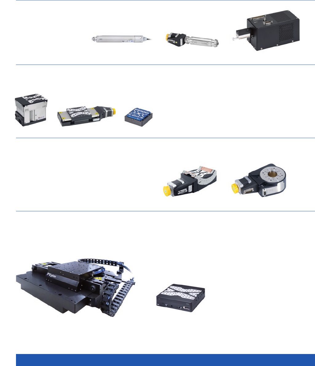
Hybrid drive, consisting of
electric motor and piezo actuator,
for optimum positioning accuracy
and minimum path deviation
Compact linear translation
stage that features two
separate moving plates on
one guiding
Introduction
WWW.PI.WS
10
Linear Actuators
n Optional force control
n Screw or voice coil drive
n Compact
Linear Stages
n Travel range up to several 100 mm
n Screw or direct drive
n Mechanical or air bearing
n Incremental or absolute encoders
n Vacuum or clean room compatible
Rotary Stages
n 360° or goniometer stages
n Worm or direct drive
n Mechanical or air bearing
n Incremental or absolute encoders
n Vacuum or clean room compatible
XY Stages
n Screw or direct drive
n Mechanical or air bearing
n Incremental or absolute encoders
n Optional aperture
Motorized Standard Products Overview
MOTION | POSITIONING
11
Stacked Systems Configured from Standard Products
n Flexible
n Fast to adapt to custom application
n Cost-efficient solution
Integrated System Solutions
n Gantries with industrial motion controllers
n Fast multi-channel photonics alignment systems
Broad Range of Standard Axes
The PI Group has many years of experience in the development and construction of highly complex motion systems with the highest
precision classes. The experience gained over the years, mainly from customized solutions, has been transferred to the standard
products. As a result, a broad spectrum of standard positioning systems has been established, which offers many options within the
individual series such as variable travel ranges, different motors, or adaptations to different ambient conditions such as a vacuum
and clean-room environments. Today, the use of PI positioning systems is very common in robust industrial environments with
high demands on lifetime and productivity.
Introduction
WWW.PI.WS
12
From Standard to Custom Products
Technological Depth for Optimized Products
Customization on all levels of integration
PI’s proprietary technological know-how and vertically integrated production are the basis for the successful development of
customized motion systems from scratch. All technologies can be adapted specifically to an application. Examples range from a
PIMag® voice coil drive for integration into an OEM system, to complex multi-axis positioning setups, to fully integrated, turn-key
system solutions.
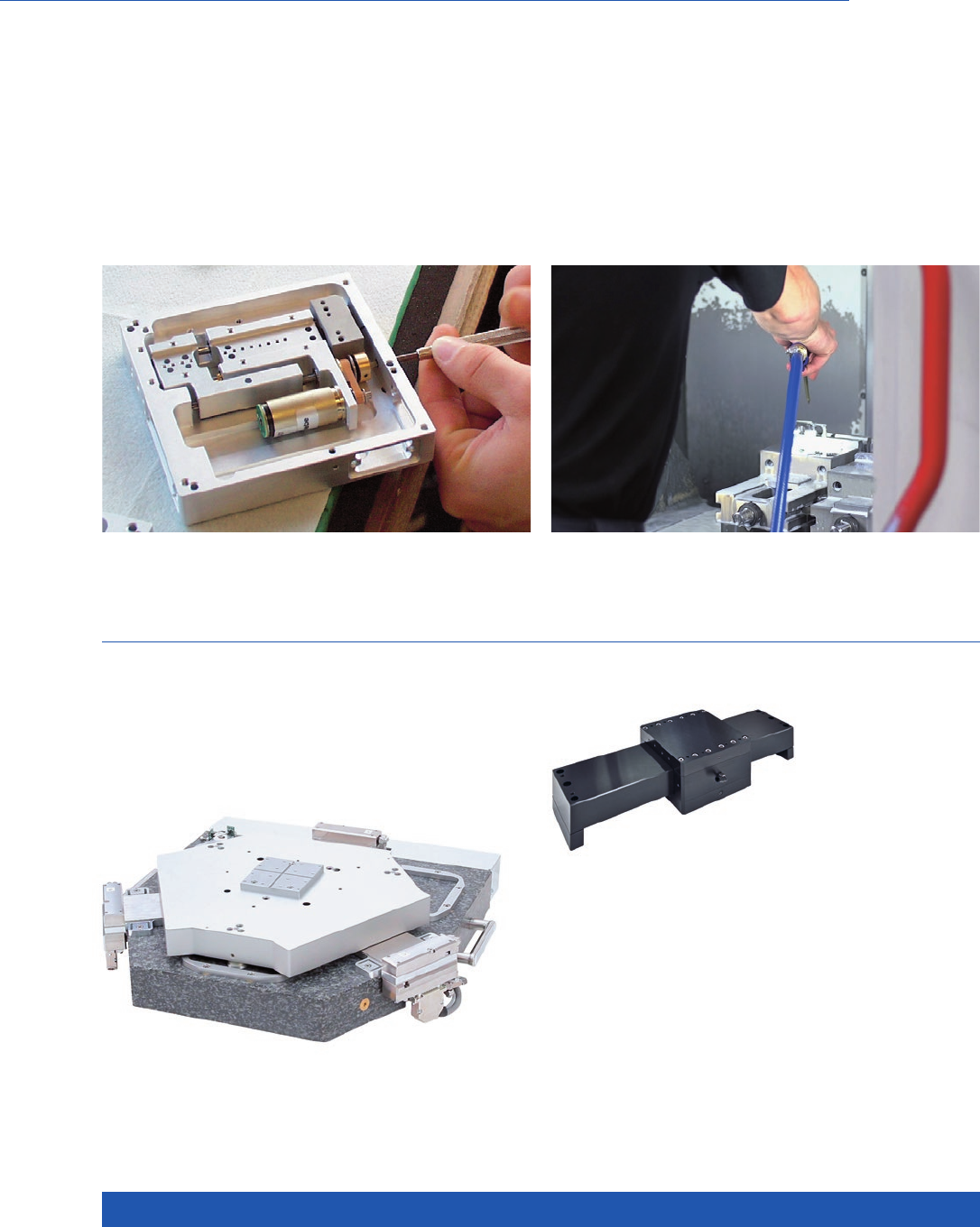
Individual assembly of a stage PI produces core components in-house for its precision positioning
systems. This applies to sensors, electronics, and motors as well as
certain milled parts with particularly low tolerances
PI’s own development of guiding technologies allows the design
of individual solutions. Linear guiding technologies such as flexures
for small displacements, air bearings for extreme requirements on
travel accuracy, or magnetic levitation for the highest demands in
up to six degrees of freedom are developed in-house. Leveraging of
long-standing piezo technology at PI Ceramic, PI is able to manufac-
ture ceramic bearings in its own facilities. For many requirements,
mechanical bearings in different precision grades from highly
qualified suppliers are used
MOTION | POSITIONING
13
Systems From a Single Source
The controller technology of ACS Motion Control ensures that even complex industrial applications can be managed by one single
source. This means that PI can offer ideal solutions from one single source to meet the demands of the most diverse industries,
which all need reliable, durable technology with increasing levels of precision.
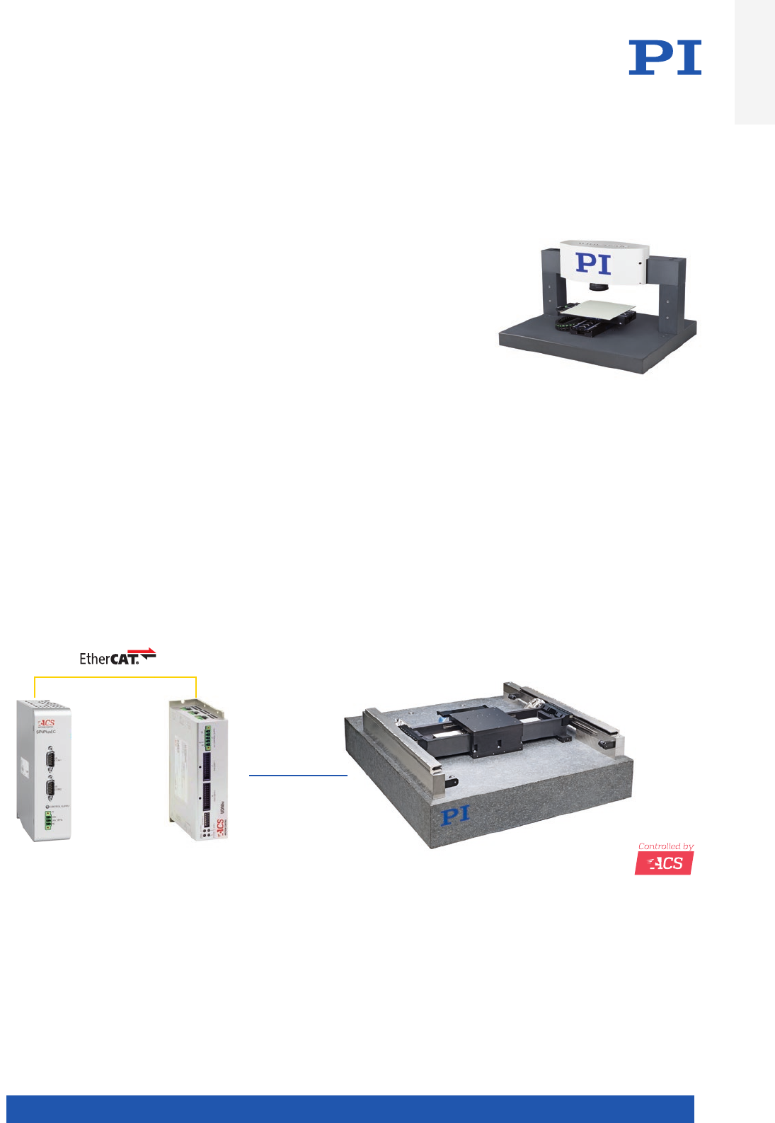
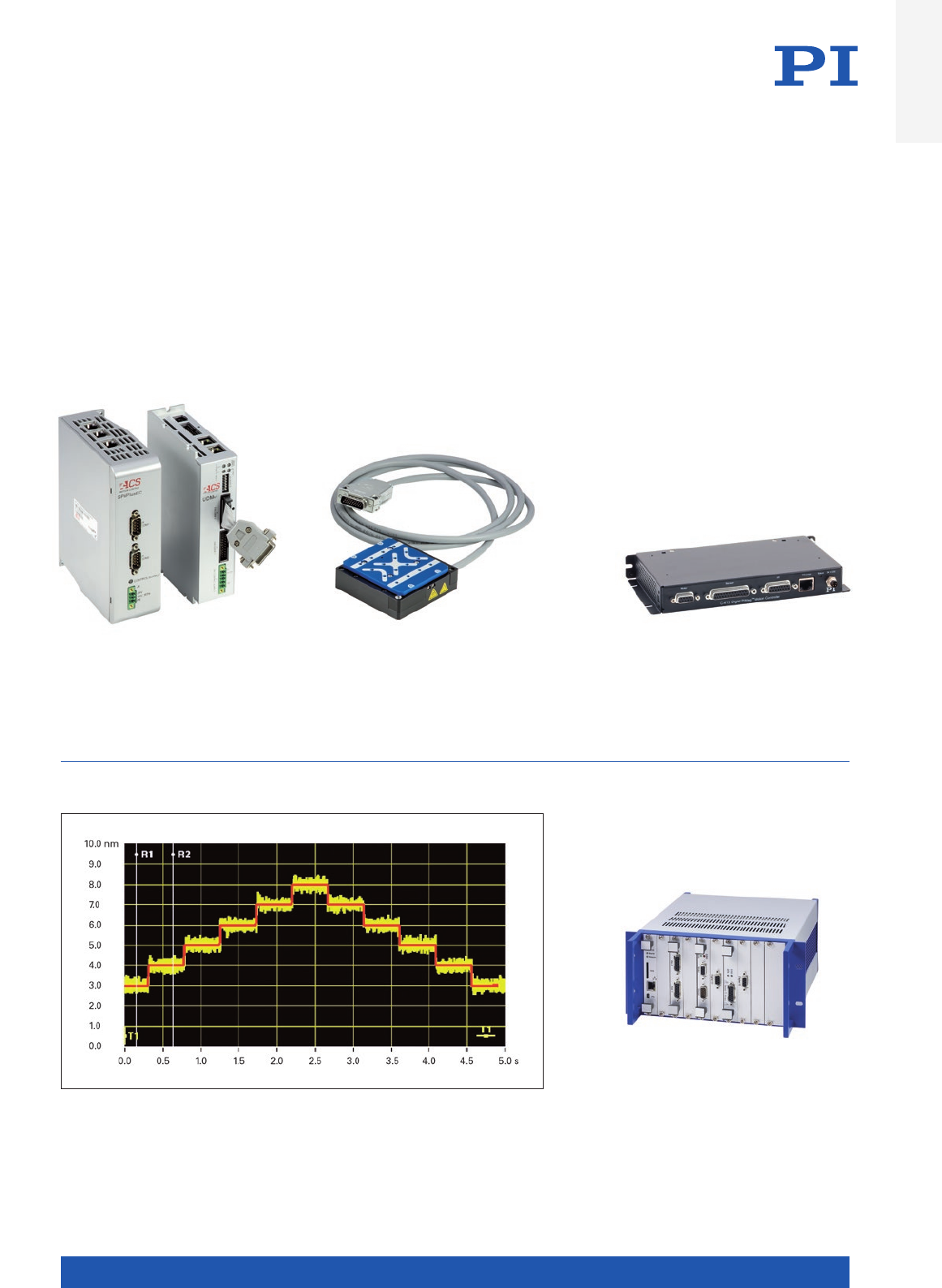
Modular multi-axis controllers from ACS for automation control are based on an internal
EtherCAT network. This modular technology allows to control stages needing a bus
voltage from 24 VDC up to 560 VDC and a peak current of 5 A up to 90 A. The ACS control
technologies are designed especially for direct drives such as voice coils and linear motors
in the best possible way enabling fast settling times, high speed stability and low jitter
OEM controllers from PI meet customers’
requirements in every aspect. They are
available for any drive technology and can
be adapted to include special functions
such as force control
Compact motion control solutions
permit the control of individual axes
with different drive technologies such
as stepper, DC or linear motors and
piezo-based drives. The modular design
allows a subsequent adaptation of
the network while using one common
control interface
Positioning stages with PIMag® linear motor and with PIOne measuring system allow
minimum incremental motion and the highest precision such as for example, the
V-551.xD linear stage. The diagram shows steps from 1 nm and the idle noise of <±0.4 nm.
In the linear motor axes, this precision can be combined with long travel ranges, high
velocities, and accelerations
Introduction
WWW.PI.WS
14
In-House Technological Expertise
All decisive technologies required for the drive or motor, the measuring system, the motion controller, and the guiding system,
are available in-house. To serve industrial applications, in-house development and the production capabilities of PIMag® magnetic
drive and PIglide air bearing technologies are essential. PI also has production capabilities for high-end mechanical parts such as
the milling of components with lowest tolerances.
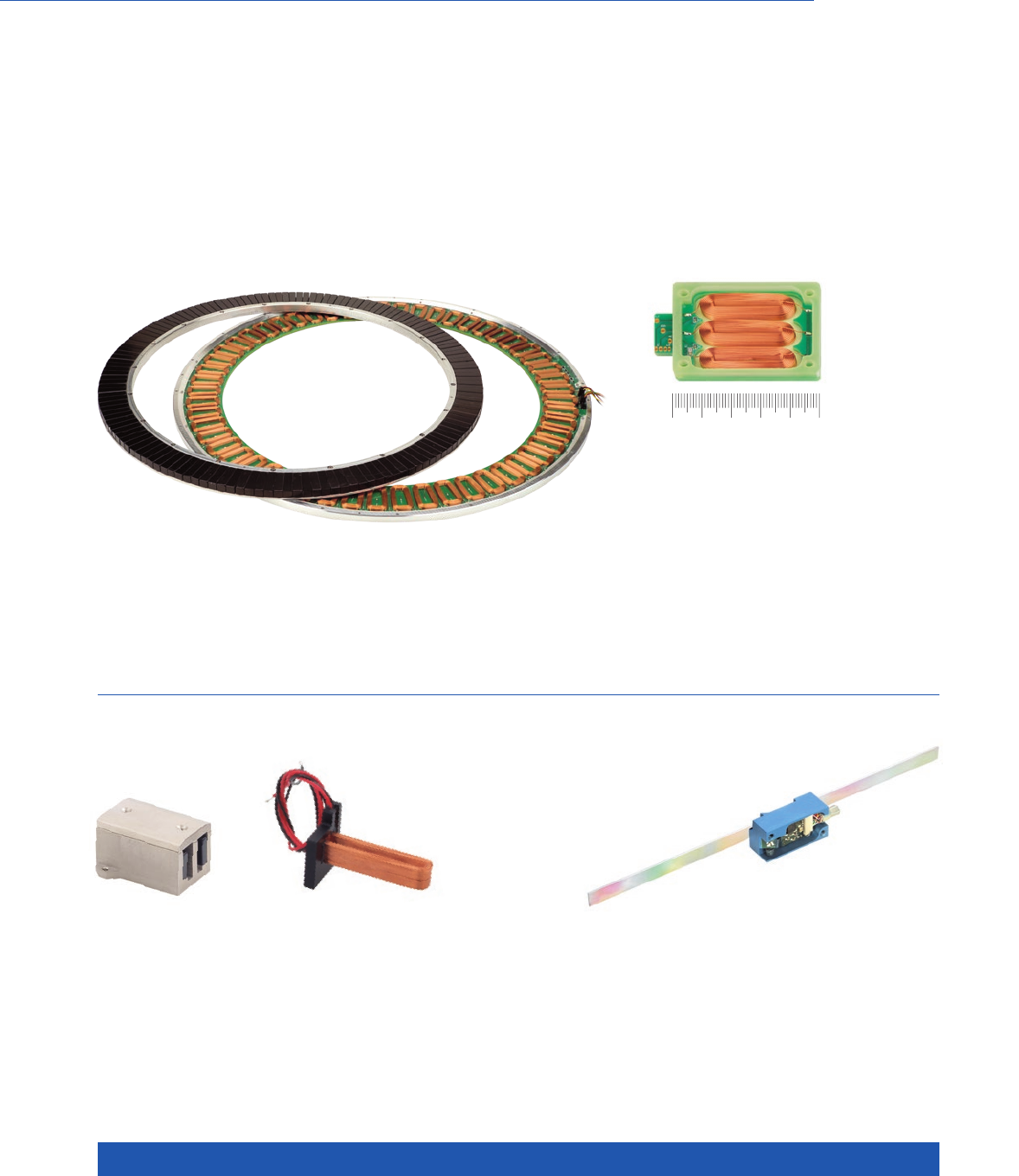
Commercially available torque motors offer very high torque but only limited
apertures. This customized PIMag® torque motor has a particularly large
aperture and it positions with high dynamics and stability while needing minimal
installation space. It can be integrated as a rotation stage on top of a PI hexapod
From Standard to Custom Products
Technological Depth for Optimized Products
PIMag® voice coil drives can be designed with a particularly compact size and
they can be directly integrated into the customers’ application. The PIMag®
technology and dedicated simulation tools allow to optimize the force-to-size
ratio for a required form factor
PIMag® linear motors with or without iron core
are the result of in-house development. In this
way, specific properties of the stages and axes
can be influenced directly. PI is in a position
to develop customized linear motor and voice
coil solutions not only for standard products
but also for customized OEM solutions, where
special features are needed. In most cases, the
form factor of such a motor will be customized
and adapted to the customers’ needs
0 10 20 30 40 50 mm
The highly precise PIOne linear encoder, one
of PI’s own measurement systems, permits a
signal period to 0.5 µm. In the controller, sine/
cosine signals are evaluated which allow for
a very high position measurement accuracy of
down to a fraction of a nanometer
MOTION | POSITIONING
15
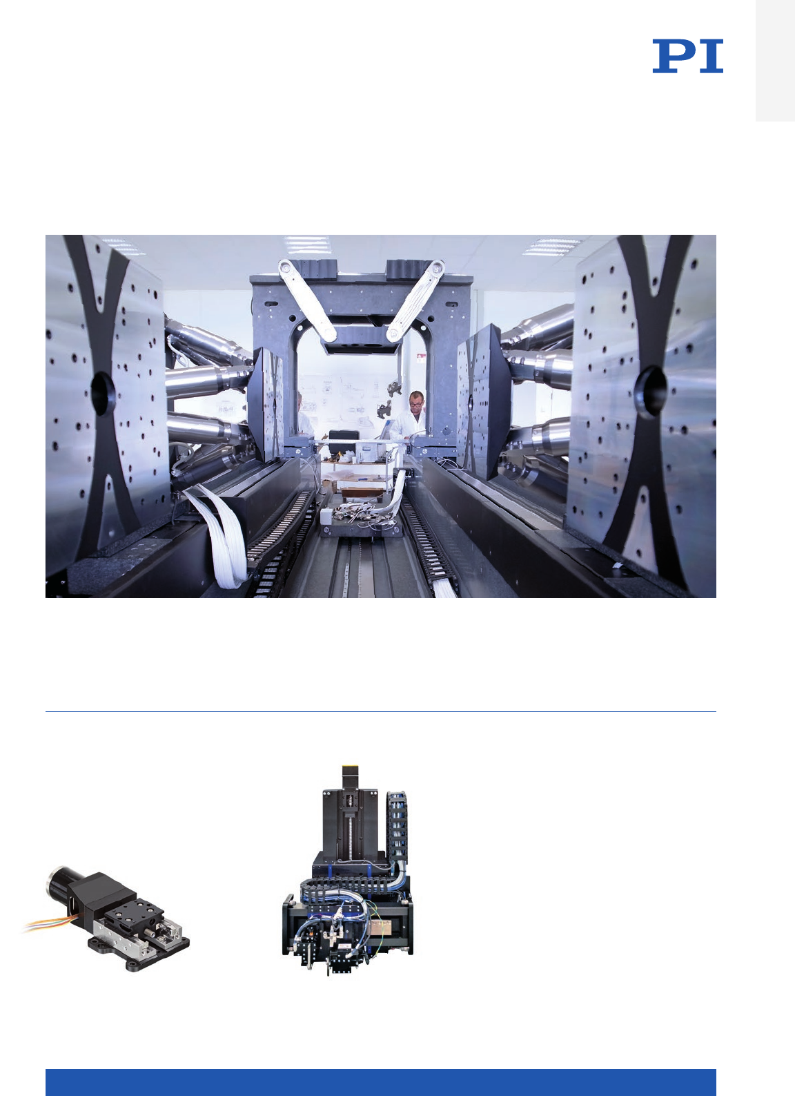
56 motors, 16 motion controllers, and 20 tons weight make the system for Microscopy and Quality Assurance (MiQA). The unique system
integrates hexapods, rotation stages, goniometers, and a custom sample stage and will be used in a beamline for X-ray microscopy and the
qualification of X-ray optics. Virtually all available PI technologies are combined here in a highly specialized solution providing the best
possible accuracy for this application, resulting in 80 nm at the tool center point over multiple stacked axes
Focusses an objective in space:
Linear stage for the “Mars 2020”
NASA mission
Coordinate measuring machines (CMM) and metrology
tools use a variety of design architectures, including
moving gantries, static gantries, cantilevered XYZ, and
many others. The most common type of CMM is com-
posed of three orthogonal axes (X, Y, and Z) operating in
a three-dimensional coordinate system. Each axis has a
position encoder that indicates the position of that axis.
The machine will read the input from the touch probe,
as directed by the operator or computer program. The
machine then utilizes the X, Y, and Z coordinates of each
of these discrete points to determine size and position
of the part being measured
Custom Examples Picture Wall
Introduction
WWW.PI.WS
16
Custom Examples Picture Wall
Complete autofocus system
with PIMag® voice coil drive. Not
only the voice coil stage is supplied
by PI but also the alignment tools and an
alignment routine to warrant highest precision
assembly of the payload
Customized parallel-kinematics stage with six degrees of freedom.
The PIMag® linear motors ensure high dynamics and precision as
required in optical alignment or fiber alignment. The solution is
based on 3 XY stages which are driven by linear motors that allow
high dynamics for the precision alignment. The SpaceFAB parallel
kinematic allows a very flat design with long strokes in x and y.
In comparison to a PI Hexapod, the footprint of the SpaceFAB is
relatively large, and the hexapod is better suited for longer vertical
strokes
The dynamics and precision of voice coil or linear motor stages is
required in vertical direction as well. For an improved position stability
PI offers various solutions for a counter balance system which can be
based on springs, magnetic solutions and pneumatic cylinders. The
picture shows a modified V-528 standard product with PIMag® direct
drive and gravity compensation for vertical applications. The compen-
sation is done by a constant force spring and is adjusted precisely to
the customers payload
MOTION | POSITIONING
17
Over the last four decades, PI (Physik Instrumente) has developed into the leading manufac-
turer of nanopositioning technology. The key element and motivation of the entrepreneurial
behavior have always remained the same: Finding the best possible solution for the customer.
PI is well known for the quality of its products and has been one of the leading players in the
global market for precision positioning technology for many years. One of the most important
building blocks for this is the team spirit within the international PI family, which is based on
mutual understanding and support that goes beyond international borders and functional
restrictions.
PI is a privately owned company with healthy growth, more than 1000 employees worldwide
and a flexible, vertically integrated organization, which enables PI to fulfill almost any request
in the field of innovative precision positioning technology. The foremost priority for PI is to
be a reliable and highly qualified partner for the customer.
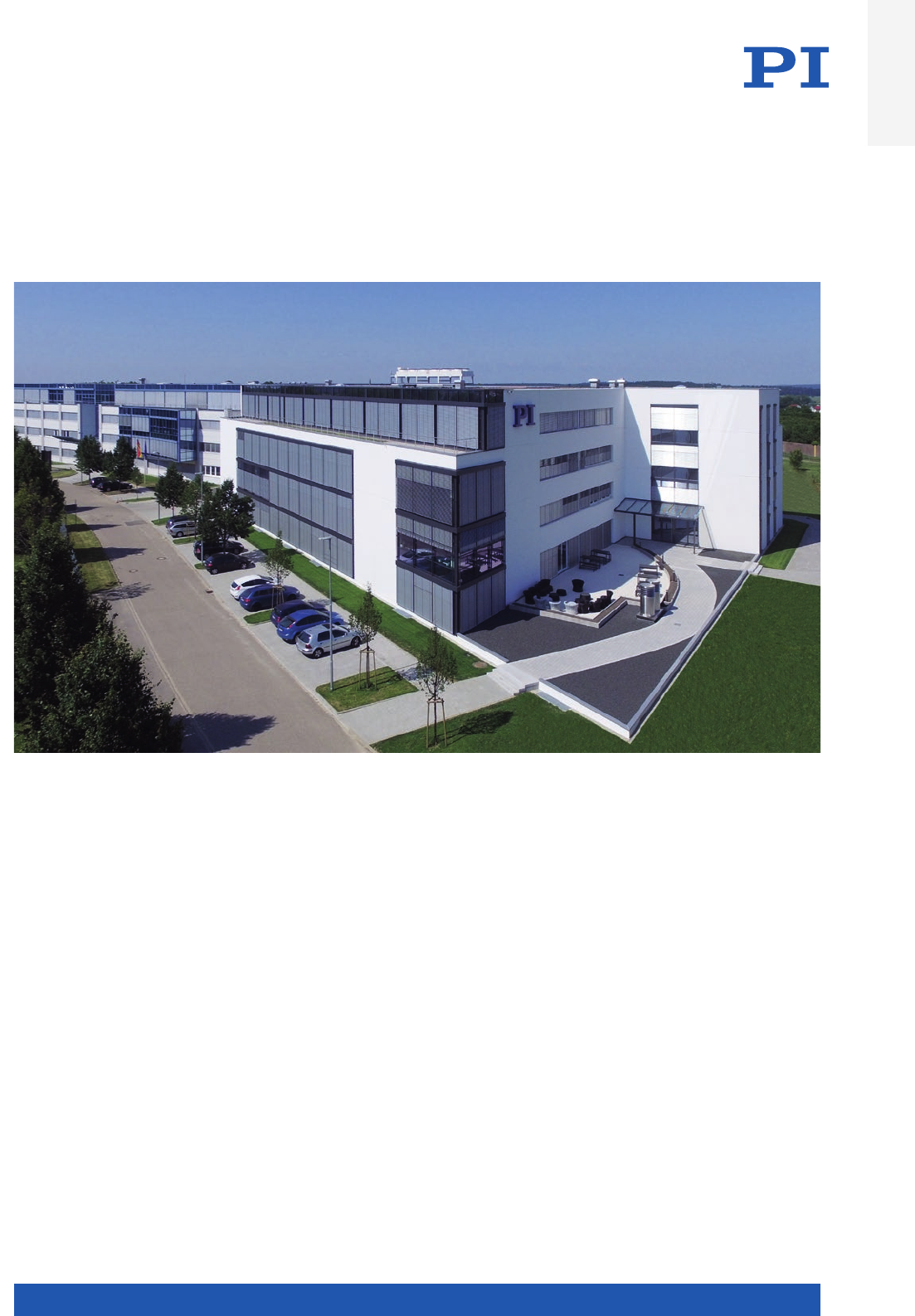
The PI headquarters in Karlsruhe, Germany, manifests the continuous growth. In front, the 2017 Technology Center
The PI Group – A Strong Partner
for Industry and Research
Introduction
WWW.PI.WS
18
Market introduction of capacitive
position sensors, implementation
in piezo-based nanopositioning
systems
New
subsidiary
in Italy
New
subsidiary
in Japan
Foundation of PI Ceramic
in Thuringia, Germany,
cornerstone for market
leadership in nano-
positioning technology
New
subsidiary
in the USA
Market introduction
of six-axis parallel-
kinematic positioning
systems (Hexapods)
Market introduction
of digital
control electronics
Market introduction
of PILine® ultrasonic
piezomotors
Market introduction
of the NEXLINE®
high-performance
piezo linear drives
Market introduction
of the magnetic
PIMag® direct drives
Acquisition
of majority shares
in miCos GmbH,
Eschbach, Germany
Founding year
of PI
New subsidiaries
in Great Britain
and France
New
subsidiary
in China
Market introduction
of the PICMA®
multilayer piezo
actuators
New subsidiaries
in Korea and
Singapore
Market introduction
of Q-Motion®
and PiezoMikes
Market introduction
of NEXACT®
piezo linear drives
Introduction
ofair bearings
Acquisition
of Nelson
Air Corp., USA
1992
1998
2001
2004
2007
1987
1970
1991
1993
2002
2011
2014
2015
1994
Acquisition of
majority shares
in ACS Motion
Control
2016
New subsidiaries
in Taiwan and the
Netherlands
Well known for the high quality of its pro-
ducts, PI (Physik Instrumente) has been
one of the leading players in the global
market for precision positioning techno-
logy for many years. PI has been develop-
ing and manufacturing standard and OEM
The PI Group Milestones
A Success Story
products with piezo or motor drives for
more than 40 years. In addition to four
locations in Germany, the PI Group is
represented internationally by fifteen
sales and service subsidiaries. All of our
customers worldwide can rely on this.
MOTION | POSITIONING
19
Market introduction of capacitive
position sensors, implementation
in piezo-based nanopositioning
systems
New
subsidiary
in Italy
New
subsidiary
in Japan
Foundation of PI Ceramic
in Thuringia, Germany,
cornerstone for market
leadership in nano-
positioning technology
New
subsidiary
in the USA
Market introduction
of six-axis parallel-
kinematic positioning
systems (Hexapods)
Market introduction
of digital
control electronics
Market introduction
of PILine® ultrasonic
piezomotors
Market introduction
of the NEXLINE®
high-performance
piezo linear drives
Market introduction
of the magnetic
PIMag® direct drives
Acquisition
of majority shares
in miCos GmbH,
Eschbach, Germany
Founding year
of PI
New subsidiaries
in Great Britain
and France
New
subsidiary
in China
Market introduction
of the PICMA®
multilayer piezo
actuators
New subsidiaries
in Korea and
Singapore
Market introduction
of Q-Motion®
and PiezoMikes
Market introduction
of NEXACT®
piezo linear drives
Introduction
ofair bearings
Acquisition
of Nelson
Air Corp., USA
1992
1998
2001
2004
2007
1987
1970
1991
1993
2002
2011
2014
2015
1994
Acquisition of
majority shares
in ACS Motion
Control
2016
New subsidiaries
in Taiwan and the
Netherlands
Introduction

WWW.PI.WS
20
Expert Consulting
The PI Group can respond precisely to what customers want: Specific require-
ments can often only be satisfied by customized solutions – solutions that can
be found by unconventional and creative thinking. Together with the customers,
PI plans and realizes individual solutions for the most varied applications and
integration levels. And that means that PI’s customers can always be sure that
they will get the best solution every time.
Customers directly benefit from:
Highly Qualified Consultancy Through Trained Specialists
Individual advice often is key to solve a complex problem. PI sales engineers
are ready to come on site with all the time necessary for a solid understanding
of the topic. Or they will gladly meet at the PI head office. All PI sales engineers
have a background in natural sciences or engineering, and have up to 20 years
of experience in optical, micro- or nanopositioning technology.
International Support
PI subsidiaries and distributors in many
countries across the world guarantee global
support – a decisive advantage, especially
for globally operating customers. PI has its
own sales and service offices in all important
markets. Moreover, the company maintains
testing devices for nanometrology on three
continents. PI Shanghai and PI USA have
additional development and manufacturing
resources that allow rapid local reaction to
custom-engineered specifications.
Time for qualified technical consultation is crucial for the success of high-tech projects
MOTION | POSITIONING
21
Unique Technological Breadth
The technological diversity of the PI Group is unrivalled all over the world.
PI develops, manufactures, and qualifies all its core technologies itself. PI is
therefore not dependent on components available on the market. That puts PI
in a position to offer its customers the most advanced products for motion and
positioning tasks – without technological restriction.
Customized Solutions
With this background, PI develops positioning solutions with innovative drive
technologies for high-tech applications worldwide. PI covers the whole motion
range from finger-tip sized nanopositioners to large-scale stages with long
travel ranges, through their plethora of differ-ent drive and guiding systems.
Core Technologies
n In-house manufacturing of piezo
components and piezo actuators
n Magnetic direct drives: linear motors
and voice coils
n Air bearings, magnetic and flexure
guides
n Comprehensive range of piezo motor
technologies
n Nanometrology sensors
n Parallel-kinematic systems for
positioning in six axes (Hexapods)
n Motion control technology
n Software
Engineering Design Expertise
and Customization
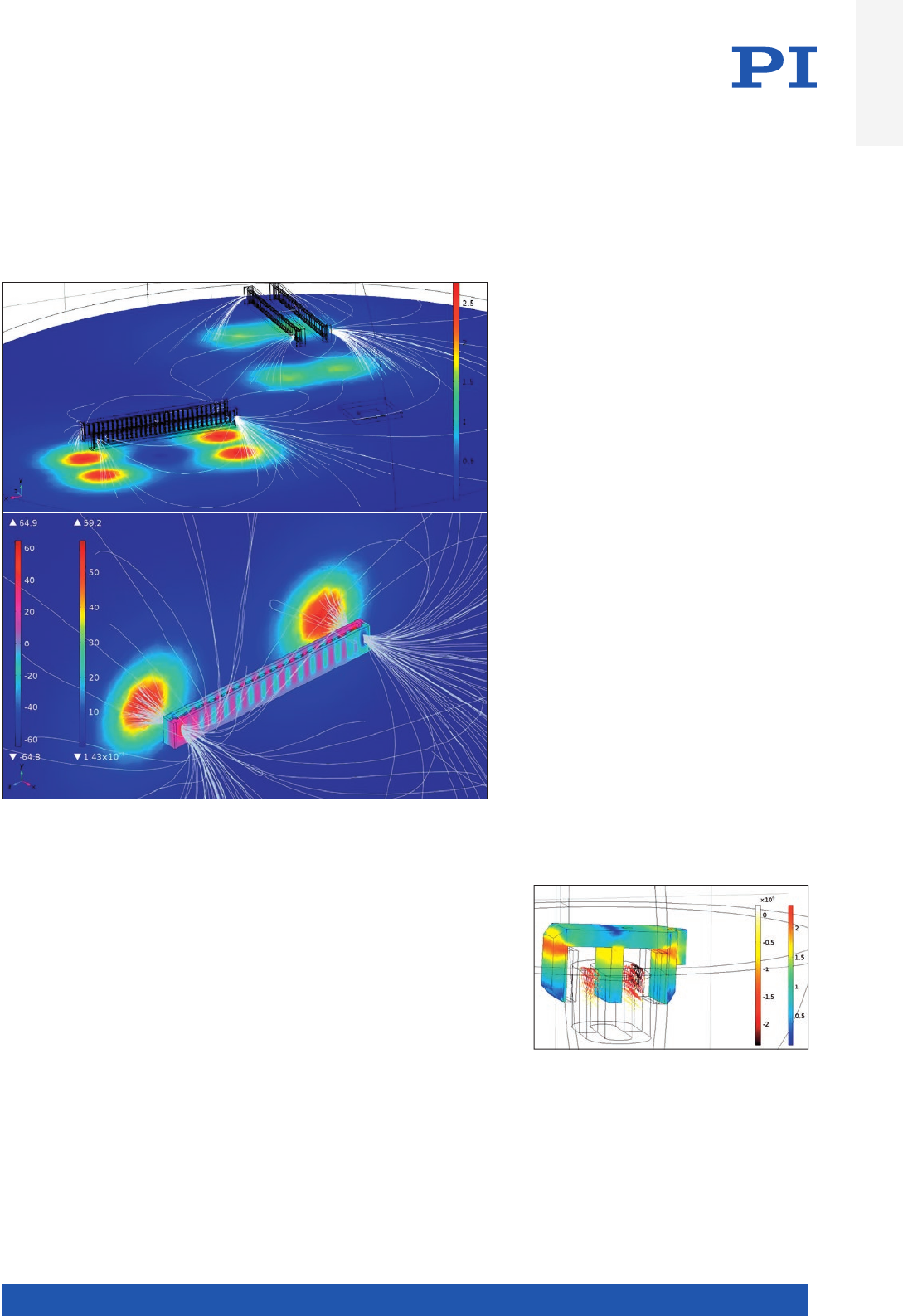
Calculation of the magnetic flux density and
currents for a novel voice coil drive allowing
multiple degrees of freedom
The development and customized design of
electromagnetic direct drives that are used for
high-resolution motion and positioning tasks
require a scientific approach to the technology.
The images show the analysis of magnetic fields
down to a magnitude of 5 µT that were used to
select the optimum position of the drive compo-
nents within an application
Introduction

WWW.PI.WS
22
Production Capabilities
A modern production management and an integrated management
system allow PI to guarantee the high quality of its products, processes,
and services. The continual improvement of organization and processes
is an integral part of the corporate culture. KAIZEN workshops and an
active innovation management are important elements for achieving
this.
The production processes for the standard range are made flexible by
the fractal production structure and it is therefore possible to manufac-
ture even large series with full process control. Active, system-based
requirements management makes it possible to dispense with compre-
hensive storage facilities.
Vertical Production Range and Production Capacity
The product spectrum ranging from the two-ton hexapod to the 10-gram
nanopositioner requires PI to have the equipment and technologies at
its disposal that allow the systems to be manufactured, assembled, and
qualified.
n 13,000 m² of overall production space
n 5,000 m² for cleanrooms
n Air-conditioned and vibration-proof measuring
conditions
n Vacuum chambers for startup and residual gas
analysis
n Measuring technology with traceable, calibrated
measuring equipment
n Monitoring of piezo actuator technology from
material composition to final inspection
n In-house manufacturing of positioning sensors
n Production hall with measuring technology for
heavy loads
n Fractal production organization
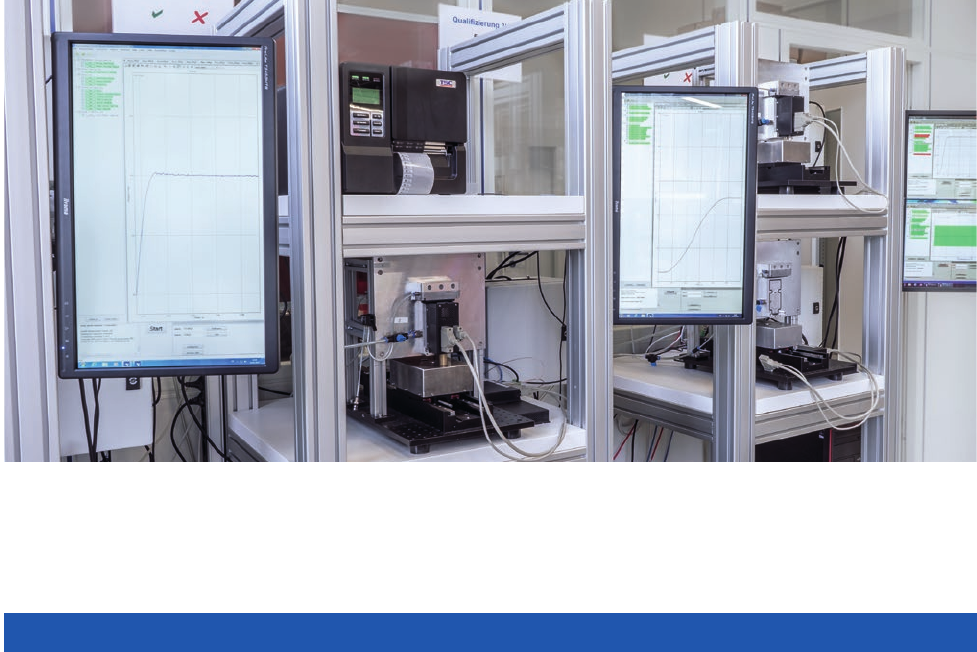
PI’s flexibility in serial production allows for fast adaptation of both processes and quantities
MOTION | POSITIONING
23
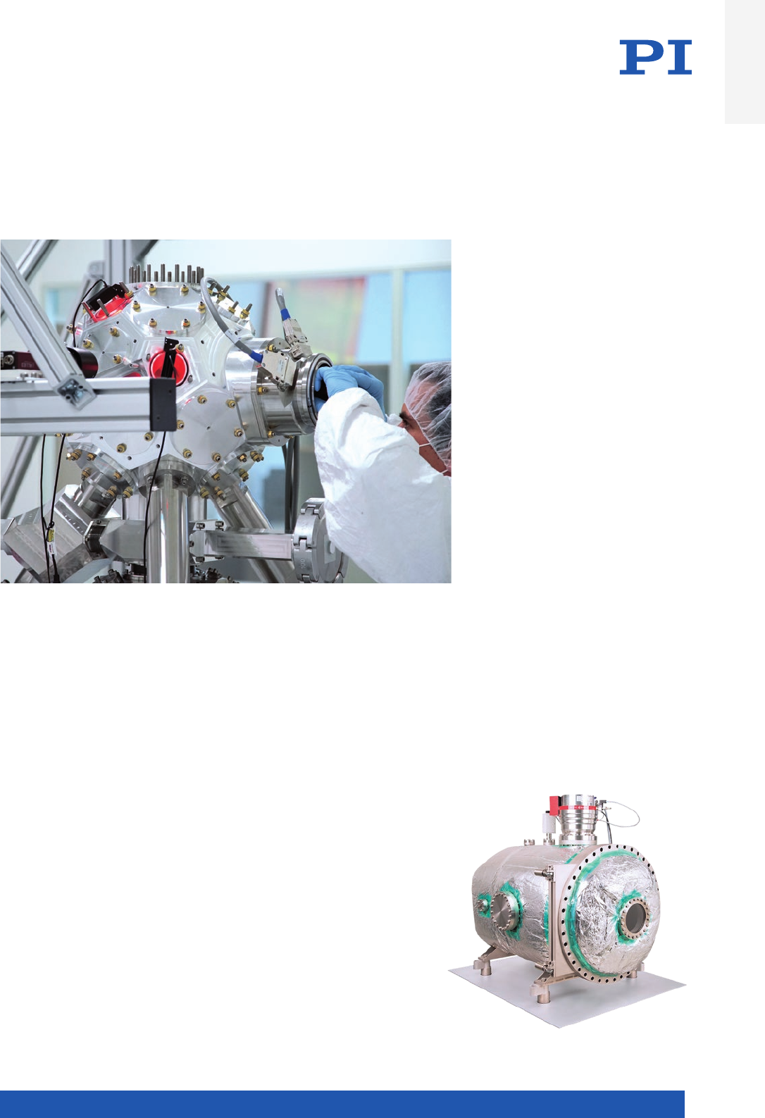
PI offers high-precision solutions for positioning in vacuum conditions to 10–10 hPa.
Positioning solutions in a vacuum follow clearly defined constraints. This applies to
the limited installation space, as well as prevention of contamination and excessive
heat input.
Selection of the optimum drive technology for the respective application and the
mechanical design must be matched exactly to the required load capacity and
velocity as well as the intended operating and planned duty cycles.
The handling regulations for vacuum positioning systems are just as important as
the design principles. Cleanrooms are available for assembling larger parts. Suitable
packaging and the corresponding instructions for the recipient are part of shipping.
Vacuum chambers are available in several sizes with vacuum levels down to 10–10 hPa,
where start-up and measurement of outgassing, but also interferometric measuring of
position accuracy under real operating conditions is possible.
At PI, several vacuum
chambers are available
in various sizes
Vacuum Know-How
Introduction
WWW.PI.WS
24
PI serves both the research and industrial markets. The complete control over the design and manufac-
turing process provides our customers with significant competitive advantages. Optimized processes
allow PI to deliver customized products in quantities up to several 100,000 units per year at low cost and
right on time. The range of OEM products offered by the PI Group varies widely, ranging from “bare”
actuators and sensors to highly integrated parallel-kinematic positioning systems. Evaluation of pre-
production run samples, test procedures, production processes and quality management are all included
in the development process.
Services
n Global account management: Close proximity to the customer thanks to international presence
n Risk assessment from design to delivery
n Depending on the task: From the drive to the turnkey system
n Copy exactly policy
n Preparation of internal and external certification
n Production of series of several 10,000 units in the shortest time
n Sustainable spare parts service
n Manufacturing and testing capacities from functional samples to mass production
From 1-off to Series:
OEM Users Benefit From Maximum Flexibility
Standardized performance control with full documentation of individual measurement charts

MOTION | POSITIONING
25
Global Service and After-Sales
On-site training is key to optimize and maximize the potential of new PI systems
Start-Up, User Training and Life Long Support
PI is dedicated to supporting its customers right from the initial consultation
through to when a customer has purchased a PI system. Beyond that, PI’s services
division is committed to ensuring that every aspect of owning a PI system is
catered for.
Global Coverage
Supported by 4 Global Service Hubs in Asia, China, Europe and USA, with field
product specialists working from these hubs, PI is able to support all technolo-
gies and customer applications via this global services team.
PI’s Standard On-Site Services
n Set up and Commissioning – On-site support to un-box, set-up and
commission the PI system
n Training Program – User training on software and programming,
through to optimization of system performance
n Maintenance Systems Health Check – Preventative maintenance to
prolong the life of the motion device
n Support – Ongoing remote and on-site support to maximize system
uptime and provide maintenance for the whole life of any system
Contracted Services
Customers subscribing to Contractual Sup-
port Services will receive commitment from
PI to achieving agreed Service Levels. These
include responding to the customer’s first
contact and providing remote technical
support, through to response times for a PI
expert to be on site, either to repair or replace
a defective unit.
Extended Warranty
Most customer applications require PI’s
systems to be operational beyond the stand-
ard warranty period. Extending the warranty
for additional year(s), is simply extending the
customers peace of mind and PI’s commit-
ment that the product will not fail due to poor
workmanship or faulty materials. Should
a customer’s system then fail due to these
conditions, PI will cover the costs to repair or
replace it.
Introduction
WWW.PI.WS
26
Application
Examples
Major
Requirements
Translation
Stages
see p. 28 ff
Z-Stages
see p. 126 ff
XY-Stages,
Gantry
Systems
see p. 138 ff,
see p. 260 ff
Rotation &
Goniometer
Stages
see p. 162 ff
Linear
Actuators
see p. 200 ff
Autofocus High dynamics
High repeatability
Compact size
High precision
L-505
L-509
L-511
MTS-65
V-522
V-524
V-528 V-900KPIC
Automated
Optical
Inspection (AOI)
Good precision
High dynamics
L-402
L-412
L-417
L-505
V-412
V-417 L-310
UPL-120 V-731
V-738
V-741
L- 611
PRS-200
UPR-100
UPR-120
Biotechnology /
Life Science
and Microscopy
High dynamics
High repeatability
Good precision
L-402
L-505
L-509
L-511
M-403
M-404
M-413
M-414
MTS-65
V-551
L-731
L-738
L-741
V-731
V-738
V-741
L- 611
PRS-200
UPR-100
UPR-120
UPR-120 Air
V-900KPIC
Digital Printing High dynamics V-412
V-417
V-508
V-522
V-524
V-528
Electronics
Manufacturing
High dynamics
Constant velocity
Position stability
L-402
L-412
L-417
V-412
V-417
V-508
V-551 A- 311
A-322
Gantry
UPR-100
UPR-120 L-220
L-239
V-273
V-275
V-277
Flatpanel
Inspection
Best straightness
and flatness
Constant velocity
High repeatability
A-110
A-121
A-123
V-412
V-417
Laser Cutting High precision
Long stroke
High dynamics
L-412
L-417
L-509
L-511
V-408
V-412
V-417
L-310
UPL-120 A-321
Gantry
L-731
L-738
L-741
V-731
V-738
V-741
L- 611
PRS-200
UPR-100
UPR-120
Laser Marking Compact size
High precision
High repeatability
HPS-170
M-110
M-122.2DD1
MTS-65
V-408
V-508
V-522
V-524
V-528
L-310
UPL-120 A-311
L-731
L-741
V-731
V-741
L- 611
M-116
PRS-200
UPR-100
UPR-120
Machine
Tooling /
Fast Tooling
High dynamics
Compact size
Constant velocity
A-131
Medical
Industry
High repeatability
Good precision
Best straightness
and flatness
A-131
L-505
M-403
M-404
M-413
M-414
V-508
V-551
L-310
UPL-120 L-731
L-738
L-741
V-731
V-738
V-741
L- 611
PRS-200
UPR-100
UPR-120
UPR-120 Air
V-900KPIC
Metrology
and Testing
Best straightness
and flatness
Constant velocity
High dynamics
A-110
A-121
A-123
HPS-170
M-406
M-511
M-521
M-531
V-508
V-522
V-524
V-528
V-551
L-310
UPL-120 L-731
L-738
L-741
V-731
V-738
V-741
A-62x
L- 611
PRS-200
UPR-100
UPR-120
UPR-120 Air
WT-85
WT-100
WT-90
WT-120
V-273
V-275
V-277
Optical
Alignment
High repeatability
High dynamics
Compact size
A-141
L-505
L-509
L-511
M-110
M-122.2DD1
M-511
M-521
M-531
L-310
UPL-120 A-62x
L- 611
M-060
M-061
M-062
M-116
PRS-200
UPR-100
UPR-120
WT-85
WT-100
WT-90
WT-120
L-220
L-239
M-227
M-228
M-229
M-230
M-232
M-235
M-238
Preferred Solutions
for High-Precision Automation Tasks
MOTION | POSITIONING
27
Application
Examples
Major
Requirements
Translation
Stages
see p. 28 ff
Z-Stages
see p. 126 ff
XY-Stages,
Gantry
Systems
see p. 138 ff,
see p. 260 ff
Rotation &
Goniometer
Stages
see p. 162 ff
Linear
Actuators
see p. 200 ff
Photonics
Probing &
Packaging
Compact size
High repeatability
High dynamics
A-110
A-121
A-123
A-141
L-505
M-403
M-404
M-413
M-414
M-511
M-521
M-531
V-408
V-522
V-524
V-528
V-551
L-306
L-310
M-501
UPL-120
L-731
L-738
L-741
V-731
V-738
V-741
L- 611
PRS-200
WT-85
WT-100
WT-90
WT-120
Precision Micro
Assembly
Most compact
size
Dynamic motion
High duty cycles
A-141
L-402
L-406
L-408
L-505
M-110
M-122.2DD1
M-406
L-310
UPL-120 L-738
V-738 DT-34
DT-80
L- 611
M-060
M-061
M-062
M-116
PRS-200
RS-40
UPR-100
UPR-120
UPR-120 Air
WT-85
WT-100
WT-90
WT-120
L-220
L-239
V-273
V-275
V-277
V-900KPIC
Sample
Inspection
Best straightness
and flatness
Force control
A-110
A-121
A-123
HPS-170
LS-180
M-511
M-521
M-531
L-310
UPL-120 Gantry A-62x
L- 611
PRS-200
UPR-100
UPR-120
UPR-120 Air
WT-85
WT-100
WT-90
WT-120
V-273
V-275
V-277
V-900KPIC
Scanning High repeatability
High dynamics
Constant velocity
Position stability
A-110
A-121
A-123
A-131
A-141
V-408
V-412
V-417
V-508
V-522
V-524
V-528
V-551
A-311
A-322
V-731
V-738
V-741
A-62x
Scientific
Instrumentation
Versatility
Networkable
solutions
Compact size
HPS-170
L-402
L-406
L-408
L-505
L-509
L-511
LS-180
M-110
M-122.2DD1
M-406
M-511
M-521
M-531
MTS-65
V-408
V-522
V-524
V-528
VT-80
L-306
L-310
M-501
UPL-120
A-311
A-322
Gantry
L-731
L-738
L-741
V-731
V-738
V-741
A-62x
DT-34
DT-80
L- 611
M-060
M-061
M-062
M-116
PRS-200
RS-40
UPR-100
UPR-120
UPR-120 Air
L-220
L-239
M-227
M-228
M-229
M-230
M-232
M-235
M-238
Semiconductor High dynamics
High precision
Position stability
Constant velocity
HPS-170
LS-180
V-522
V-524
V-528
V-551
L-306
L-310
M-501
UPL-120
A-311
A-322
Gantry
L-731
L-738
L-741
V-731
V-738
V-741
L- 611
PRS-200
UPR-100
UPR-120
UPR-120 Air
L-220
L-239
Introduction
WWW.PI.WS
28
Translation Stages

MOTION | POSITIONING
29
Precision Linear Stages ............................................................................................................................................................ 30
L-402 Miniature Linear Stage ........................................................................................ 30
M-110 / M-111 / M-112 Compact Linear Stage ............................................................... 32
L-406 Compact Linear Stage .......................................................................................... 34
L-408 Compact Linear Stage .......................................................................................... 36
V-408 PIMag® Linear Stage ............................................................................................ 38
VT-80 Linear Stage ........................................................................................................ 40
M-406 Precision Linear Stage ........................................................................................ 42
M-403 Precision Translation Stage ................................................................................ 44
M-404 Precision Translation Stage ................................................................................ 46
M-413 High-Load Precision Stage ................................................................................. 48
M-414 High-Load Precision Stage ................................................................................. 50
L-412 High-Load Linear Stage ....................................................................................... 52
V-412 PIMag® High-Load Linear Stage ........................................................................... 56
L-417 High-Load Linear Stage ....................................................................................... 60
V-417 PIMag® High-Load Linear Stage ........................................................................... 64
LS-180 Linear Stage for Heavy Loads ............................................................................ 68
High-Precision Linear Stages ................................................................................................................................................... 72
L-505 Compact Linear Stage .......................................................................................... 72
V-522 / V-524 / V-528 High-Dynamics PIMag® Linear Stage ........................................... 76
V-508 PIMag® Precision Linear Stage ............................................................................ 78
M-122.2DD1 Micro Translation Stage ............................................................................ 80
MTS-65 Miniature Linear Stage ..................................................................................... 82
M-105 / M-106 Microtranslation Stage .......................................................................... 84
L-509 Precision Linear Stage ......................................................................................... 86
L-511 High-Precision Linear Stage ................................................................................. 94
V-551 PIMag® Precision Linear Stage ............................................................................ 102
M-511 / M-521 / M-531 High-Precision Linear Stage ...................................................... 106
HPS-170 High-Precision Linear Stage for Heavy Loads ................................................. 108
PIglide Linear Air Bearing Stages ............................................................................................................................................ 112
A-141 PIglide MB Miniature Linear Stage with Air Bearings ......................................... 112
A-121 PIglide AT1 Linear Stage with Air Bearings ......................................................... 114
A-123 PIglide AT3 Linear Stage with Air Bearings ......................................................... 116
A-110 PIglide LC Linear Stage with Air Bearings ........................................................... 120
A-131 PIglide VC Voice Coil Linear Stage with Air Bearings .......................................... 124
Z Stages ................................................................................................................................................................................... 126
L-306 Compact Precision Z Stage .................................................................................. 126
L-310 Precision Z Stage ................................................................................................. 128
M-501 Precision Z Stage ................................................................................................ 132
UPL-120 Precision Z Stage ............................................................................................ 134
Translation Stages
WWW.PI.WS
30
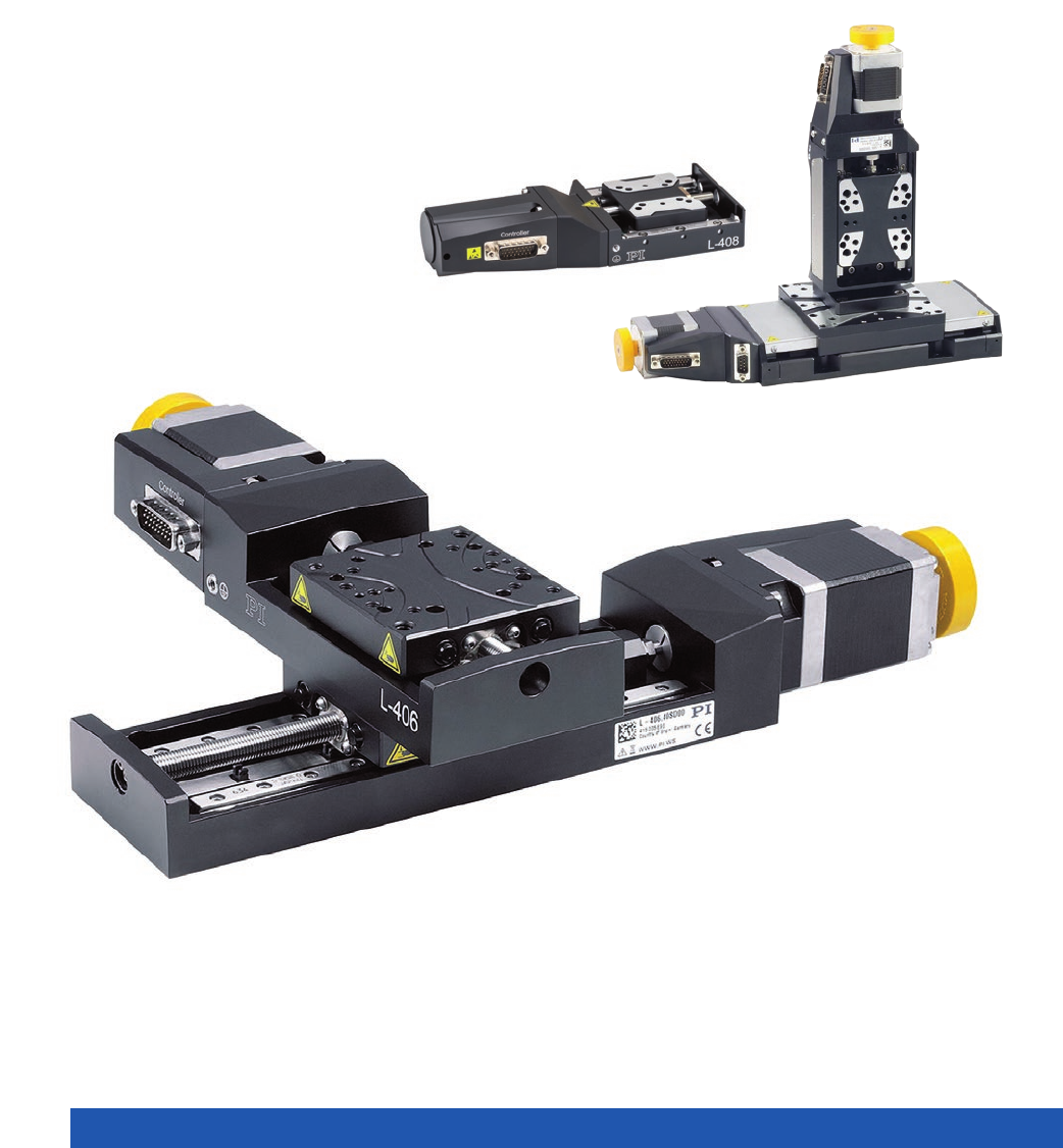
With DC or Stepper Motor
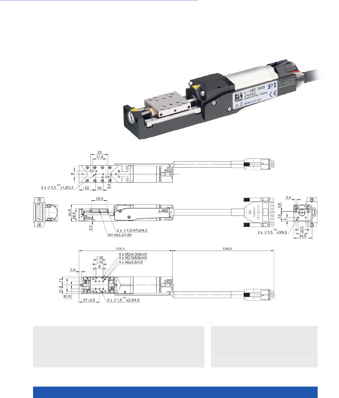
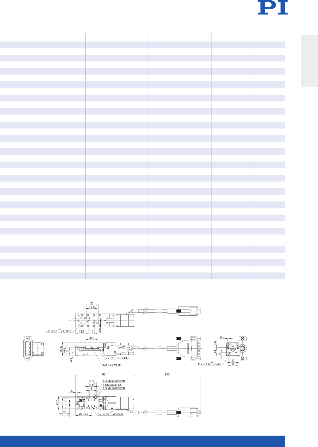
L-402 Miniature Linear Stage
n Travel range 13 mm
n Unidirectional repeatability to 0.5 µm
n Velocity to 5 mm/s
n Load capacity to 1 kg
n Integrated reference point and limit switch
n Crossed roller guides, anti-creep
n Directly mountable XY and XYZ combinations
>> Incremental Encoder
>> Vacuum-Compatible Versions
Technology Glossary ...................... page 290
Applications
n Automation
n Precision Micro Assembly
n Scientific Instrumentation
L-402.10DD, dimensions in mm
MOTION | POSITIONING
31
L-402.10SD, dimensions in mm
L-402.10DD L-402.10SD Unit Tolerance
Motion and positioning
Travel range 13 13 mm
Integrated sensor Rotary encoder –
Design resolution 0.122 2.5 (full step) µm
Sensor resolution rotary encoder 4096 – Cts./rev.
Minimum incremental motion 1 0.5 µm typ.
Unidirectional repeatability 1 0.5 µm typ.
Bidirectional repeatability ±5 ±5 µm typ.
Pitch ±175 ±175 µrad typ.
Yaw ±125 ±125 µrad typ.
Straightness ±3 ±3 µm typ.
Flatness ±3 ±3 µm typ.
Velocity 5 5 mm/s max.
Reference and limit switches Optical Optical
Mechanical properties
Drive screw Leadscrew Leadscrew
Drive screw pitch 0.5 0.5 mm
Load capacity 10 10 N max.
Push/pull force 10 10 N max.
Holding force 10 10 N max.
Permissible lateral force 5 5 N max.
Permissible torque in θX, θY
, θZ1 1 N·m max.
Drive properties
Motor type DC motor 2-phase stepper motor
Step resolution – 200 Full steps/rev.
Operating voltage, nominal 24 24 V nom.
Operating voltage, max. 48 48 V max.
Miscellaneous
Operating temperature range 5 to 40 5 to 40 °C
Material Aluminum, anodized,
stainless steel
Aluminum, anodized,
stainless steel
Mass 0.16 0.15 kg
Cable length 0.135 0.25 m ±10 mm
Connector HD Sub-D 26 (m) HD Sub-D 26 (m)
Recommended controllers C-863 (single axis) C-663.12 (single axis)
All cables required for operation with the ordered controller are included in the scope of delivery. The cable length is 3 m.
Motion controllers for >1 axis are available on www.pi.ws. Ask about custom designs!
Translation Stages
WWW.PI.WS
32
XY(Z) Combinations with a Variety of Drives and Travel Ranges
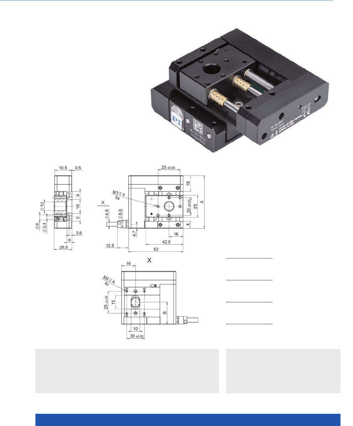
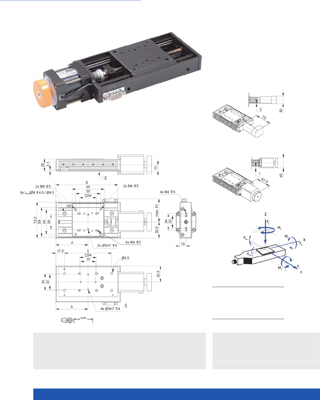
M-110 / M-111 / M-112 Compact Linear Stage
n Very compact due to folded drive
n Stepper motors and closed-loop DC motors
n Sliding thread and ball screws
n Noncontact reference and limit switches
n XY setups can be mounted directly
n Larger quantities available quickly
>> Incremental Encoder
Technology Glossary ...................... page 290
Applications
n Automation
n Precision Micro Assembly
n Scientific Instrumentation
M-11x.xxx1, dimensions in mm
A B
M-110.1DG1
M-110.2DG1
M-110.12S1
M-110.22S1
60 25
M-111.1DG1
M-111.2DG1
M-111.12S1
M-111.22S1
70 30
M-112.1DG1
M-112.2DG1
M-112.12S1
M-112.22S1
80 35

MOTION | POSITIONING
33
M-110.1DG1
M-111.1DG1
M-112.1DG1
M-110.12S1
M-111.12S1
M-112.12S1
M-110.2DG1
M-111.2DG1
M-112.2DG1
M-110.22S1
M-111.22S1
M-112.22S1
Unit Tolerance
Motion and
positioning
Travel range 5 / 15 / 25 5 / 15 / 25 5 / 15 / 25 5 / 15 / 25 mm
Integrated sensor Rotary encoder – Rotary encoder –
Sensor resolution 2048 2048 Cts./rev.
Design resolution (1) 0.0069 0.00029 0.0086 0.00036 µm
Min. incremental
motion (1)
0.05 0.02 0.2 0.2 µm typ.
Backlash 2 2 4 4 µm typ.
Unidirectional
repeatability
0.25 0.25 0.15 0.15 µm typ.
Pitch / yaw ±50 / ±150 / ±150 ±50 / ±150 / ±150 ±50 / ±150 / ±150 ±50 / ±150 / ±150 µrad
Velocity 1 / 1.5 / 1.5 1 / 1 / 1 1.5 / 2 / 2 1 / 1 / 1 mm/s max.
Mechanical
properties
Drive screw type Leadscrew Leadscrew Ball screw Ball screw
Drive screw pitch 0.4 0.4 0.5 0.5 mm
Gear ratio 256:9 256:9 256:9 256:9
Step resolution – 24 – 24 Full steps/
rev.
Load capacity 30 / 30 / 20 30 / 30 / 20 30 / 30 / 20 30 / 30 / 20 N max.
Push/pull force 10 10 10 10 N max.
Holding force 10 10 10 10 N max.
Permissible lateral
force
15 / 10 / 10 15 / 10 / 10 15 / 10 / 10 15 / 10 / 10 N max.
Drive properties
Motor type DC gear motor 2-phase
stepper motor
DC gear motor 2-phase
stepper motor
Operating voltage 0 to ±12 – 0 to ±12 – V
Motor power 0.52 / 1.75 / 1.75 1.5 0.52 / 1.75 / 1.75 1.5 W
Nominal current
per phase
160 / 320 / 320 250 160 / 320 / 320 250 mA
Reference and limit
switches
Hall effect Hall effect Hall effect Hall effect
Miscellaneous
Operating
temperature range
–20 to 65 –20 to 65 –20 to 65 –20 to 65 °C
Material Al (black
anodized)
Al (black
anodized)
Al (black
anodized)
Al (black
anodized)
Mass 0.25 / 0.27 / 0.3 0.25 / 0.27 / 0.3 0.25 / 0.27 / 0.3 0.25 / 0.27 / 0.3 kg
Cable length 0.5 0.5 0.5 0.5 m
Connection HD Sub-D 26 (m) HD Sub-D 26 (m) HD Sub-D 26 (m) HD Sub-D 26 (m)
Recommended
controllers
C-863
C-884
C-663.12 C-863
C-884
C-663.12
(1) With recommended controller.
Ask about custom designs!
Translation Stages
WWW.PI.WS
34
For Loads up to 10 kg
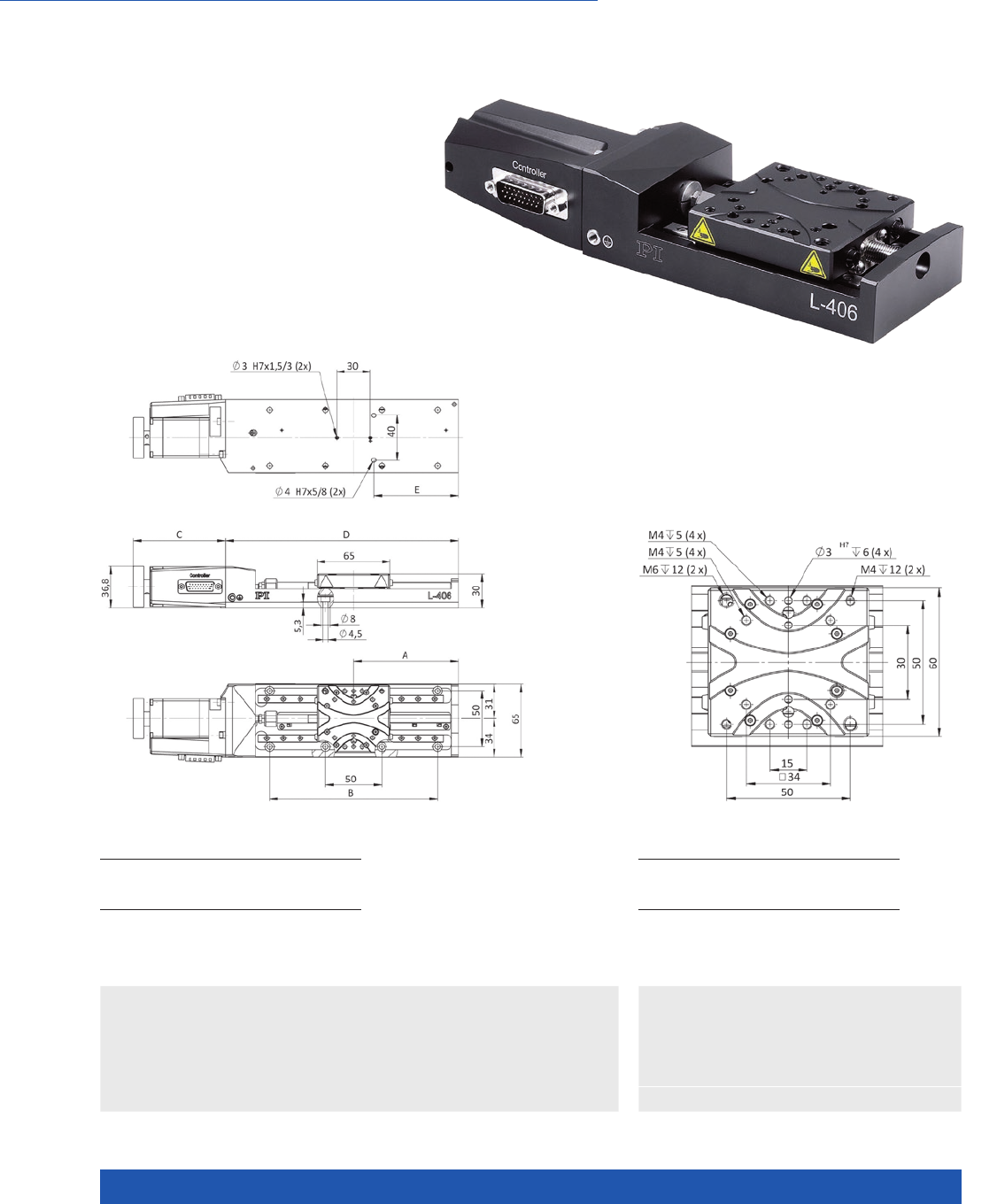
L-406 Compact Linear Stage
n Travel ranges from 26 mm to 102 mm
(1” to 4”)
n Stepper motor or DC servo motor with
and without gearhead
n Direction-sensing reference point switch
n Integrated optical limit switches
>> Incremental Encoder
>> Vacuum-Compatible Versions
Technology Glossary ...................... page 290
Applications
n Automation
n Precision Micro Assembly
n Scientific Instrumentation
A B C D E
L- 4 0 6.10SD00
L-406.20SD00
L-406.40SD00
55,5
68,5
93,5
–
100
150
82
82
82
132
158
208
62,5
75,5
75,5
L-406, dimensions in mm
A B C D E
L-406.10DG10
L-406.20DG10
L-406.40DG10
55,5
68,5
93,5
–
100
150
73,5
73,5
73,5
132
158
208
62,5
75,5
75,5
Detail drawing of the L-406 motion platform,
dimensions in mm

MOTION | POSITIONING
35
L-406.10DD10
L-406.20DD10
L-406.40DD10
L-406.10DG10
L-406.20DG10
L-406.40DG10
L-406.10SD00
L-406.20SD00
L-406.40SD00
Unit Tolerance
Linear stage with
DC motor and rotary
encoder
Linear stage with DC
gear motor and rotary
encoder
Linear stage with
stepper motor
Motion and positioning
Travel range 26 / 52 / 102 26 / 52 / 102 26 / 52 / 102 mm
Integrated sensor Rotary encoder Rotary encoder –
Sensor resolution rotary
encoder
4096 2048 – Cts./rev.
Design resolution 0.244 0.0165 5 (full step) µm
Minimum incremental
motion
0.5 0.2 0.2 µm typ.
Unidirectional
repeatability
0.5 0.5 0.5 µm typ.
Bidirectional
repeatability
±5 ±5 ±5 µm typ.
Pitch / yaw ±70 / ±90 / ±100 ±70 / ±90 / ±100 ±70 / ±90 / ±100 µrad typ.
Straightness / flatness ±2 / ±4 / ±6 ±2 / ±4 / ±6 ±2 / ±4 / ±6 µm typ.
Max. velocity 20 3 20 mm/s max.
Reference and limit
switches
Optical Optical Optical
Mechanical properties
Guide type Recirculating ball
bearing
Recirculating ball
bearing
Recirculating ball
bearing
Drive screw type Leadscrew Leadscrew Leadscrew
Drive screw pitch 1 1 1 mm
Gear ratio – 2401:81 –
Load capacity 100 100 100 N max.
Push/pull force 15 100 50 N max.
Permissible lateral force 50 50 50 N max.
Holding force 15 100 50 N max.
Permissible torque
in θX, θY
, θZ
7. 5 7. 5 7. 5 N·m max.
Drive properties
Motor type DC motor DC gear motor 2-phase stepper motor
Step resolution – – 200 Full steps/
rev.
Operating voltage,
nominal
24 24 24 V nom.
Operating voltage, max. 48 48 48 max.
Miscellaneous
Operating temperature
range
5 to 40 5 to 40 5 to 40 °C
Material Aluminum, steel Aluminum, steel Aluminum, steel
Mass 0.8 / 0.9 / 1.0 0.8 / 0.9 / 1.0 0.8 / 0.9 / 1.0 kg ±5 %
Moved mass 0.16 0.16 0.16 kg ±5 %
Connector HD Sub-D 26 (m) HD Sub-D 26 (m) HD Sub-D 26 (m)
Recommended
controllers
C-863 (single axis)
C-884 (up to 6 axes)
C-885 with
C-863.20C885
(to 40 axes)
ACS modular controller
C-863 (single axis)
C-884 (up to 6 axes)
C-885 with
C-863.20C885
(to 40 axes)
ACS modular controller
C-663.12 (single axis)
SMC Hydra
(double axis)
C-885 with
C-663.12C885
(up to 20 axes)
ACS modular controller
All cables required for operation with the ordered controller are included in the scope of delivery.
The cable length is 3 m. Cable for connecting to other controllers can be ordered as accessory.
Ask about custom designs!
Translation Stages
WWW.PI.WS
36
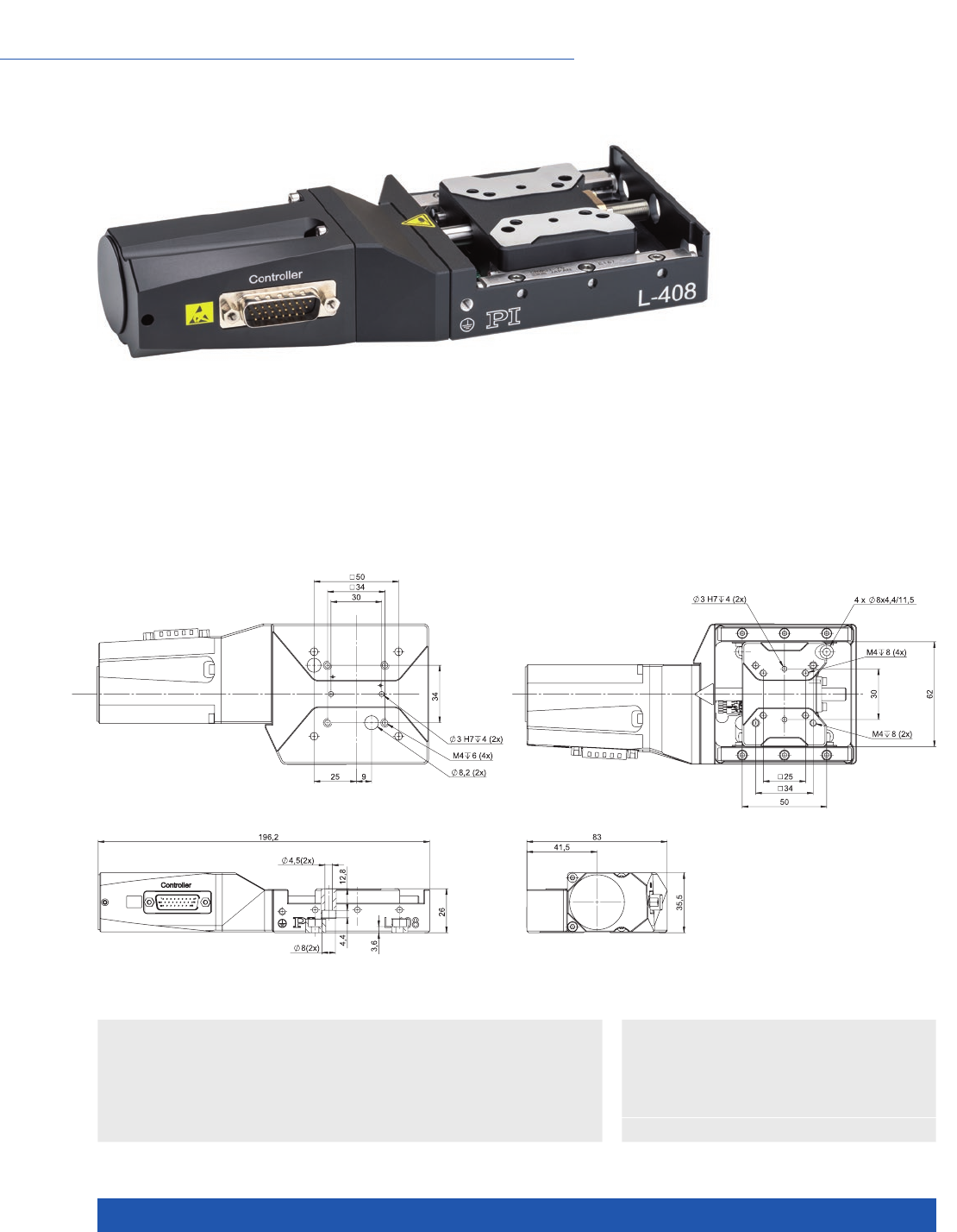
For Loads up to 200 N
L-408 Compact Linear Stage
>> Incremental Encoder
Technology Glossary ...................... page 290
Applications
n Automation
n Precision Micro Assembly
n Scientific Instrumentation
n Travel range 25 mm
n Stepper motor, DC or DC gear motor
n Precision sliding-thread spindle
n Crossed roller guides for high load capacity and precision,
anti-creep
n Integrated optical limit switches
n Optical reference point switch with direction sensing
L-408.503232 and L-408.504232, dimensions in mm

MOTION | POSITIONING
37
L-408.504232 L-408.503232 L-408.501200 Unit Tolerance
Motion and positioning
Travel range 25 25 25 mm max.
Integrated sensor Rotary encoder Rotary encoder –
Sensor resolution 2048 4096 – Cts./rev.
Design resolution 0.008 0.122 2.5 µm
Minimum incremental
motion
0.1 0.5 0.1 µm typ.
Unidirectional
repeatability
0.5 0.5 0.5 µm typ.
Bidirectional
repeatability
±5 ±5 ±5 µm typ.
Pitch / yaw ±100 ±100 ±100 µrad typ.
Straightness / flatness ±2 ±2 ±2 µm typ.
Max. velocity 1.1 10 10 mm/s max.
Reference and limit
switches
Hall effect Hall effect Hall effect
Reference point switch
repeatability
1 1 1 µm typ.
Mechanical properties
Guide type Crossed roller guide
with anti-creep system
Crossed roller guide
with anti-creep system
Crossed roller guide
with anti-creep system
Drive screw Leadscrew Leadscrew Leadscrew
Drive screw pitch 0.5 0.5 0.5 mm
Gear ratio 2401:81 – –
Push/pull force 50 50 40 N max.
Holding force 50 50 40 N max.
Load capacity 200 200 200 N max.
Permissible lateral force 100 100 100 N max.
Permissible torque in θX15 15 15 N·m max.
Permissible torque
in θY
, θZ
10 10 10 N·m max.
Drive properties
Motor type DC gear motor DC motor 2-phase stepper motor
Operating voltage,
nominal
24 24 24 V nom.
Operating voltage, max. 48 48 48 V max.
Step resolution – – 200 Full steps/
rev.
Miscellaneous
Operating temperature
range
5 to 40 5 to 40 5 to 40 °C
Material Aluminum black
anodized, steel
Aluminum black
anodized, steel
Aluminum black
anodized, steel
Mass 0.87 0.87 0.98 kg ±5 %
Moved mass 0.155 0.155 0.155 kg ±5 %
Connector HD Sub-D 26 HD Sub-D 26 HD Sub-D 26
Recommended
controllers
C-863 (single axis)
C-884 (up to 6 axes)
C-885 with
C-863.20C885
(to 40 axes)
ACS modular controller
C-863 (single axis)
C-884 (up to 6 axes)
C-885 with
C-863.20C885
(to 40 axes)
ACS modular controller
C-663.12 (single axis)
SMC Hydra
(double axis)
C-885 with
C-663.12C885
(up to 20 axes)
ACS modular controller
All cables required for operation with the ordered controller are included in the scope of delivery.
The cable length is 3 m. Cable for connecting to other controllers can be ordered as accessory.
Ask about custom designs!
Translation Stages
WWW.PI.WS
38
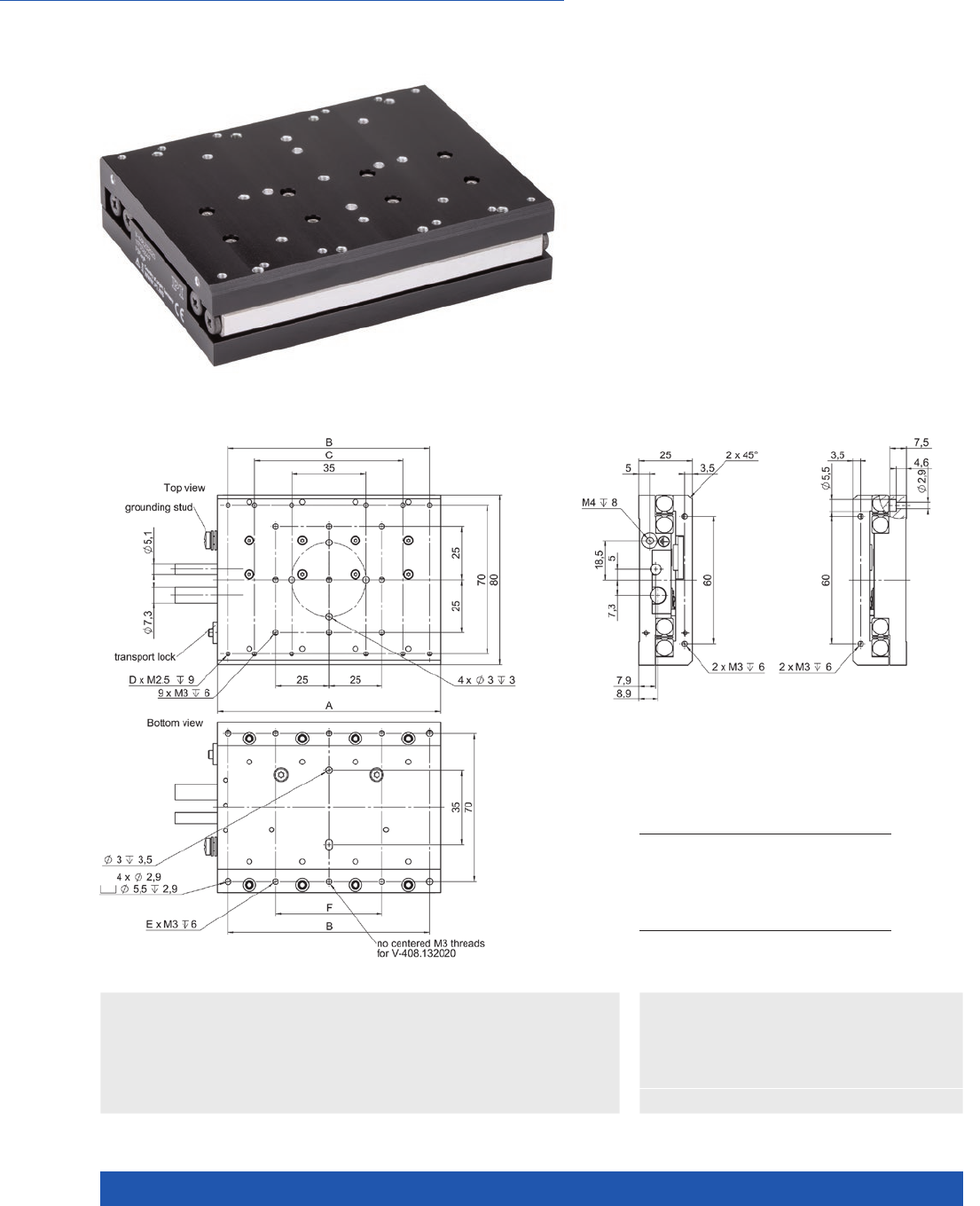
Inexpensive, with Linear Motor
V-408 PIMag® Linear Stage
>> Linear Encoder
>> PIMag® Magnetic Linear Motors
Technology Glossary ...................... page 290
Applications
n Automation
n Laser Cutting
n Laser Marking
n Photonics
n Scanning
n Scientific Instrumentation
n Iron core 3-phase linear motor
n Crossed roller bearings for high load
capacity, anti-creep
n Minimum incremental motion 20 nm
n Bidirectional repeatability ±0.1 µm
n Compact design
n Low price
V-408.132020 V-408.232020
travel range
A
B
C
D
E
F
25
80
70
n/a
8
4
25
50
105
95
70
12
6
50
V-408, dimensions in mm

MOTION | POSITIONING
39
V-408 Unit Tolerance
Motion and positioning
Travel range V-408.132020: 25
V-408.232020: 50
mm
Integrated Sensor Incremental linear encoder
Sensor signal period 80 µm
Sensor resolution 10 (1) nm typ.
Min. incremental motion 20 nm typ.
Bidirectional repeatability ±0.1 µm typ.
Pitch / Yaw ±150 µrad typ.
Straightness / flatness ±4 µm typ.
Velocity V-408.132020: 1.2
V-408.232020: 1.5
m/s max.
Mechanical properties
Load capacity in Z 80 N max.
Permissible lateral force 80 N max.
Permissible torque in θX2.3 N·m max.
Permissible torque in θY
, θZ1.3 N·m max.
Moved mass V-408.132020: 0.23
V-408.232020: 0.3
kg
Mass without cable V-408.132020: 0.5
V-408.232020: 0.65
kg
Overall mass V-408.132020: 0.79
V-408.232020: 0.94
kg
Guide type Crossed roller guide with anti-creep system
Drive properties
Drive type PIMag® Linear motor, iron core, 3-phase
Intermediate circuit voltage 48 V DC max.
Peak force 14 N typ.
Nominal force 5 N typ.
Peak current, effective 3.2 A typ.
Nominal current, effective 1.1 A typ.
Force constant, effective 4.60 N/A typ.
Resistance phase-phase 1.23 Ω typ.
Inductance phase-phase 0.97 mH typ.
Back EMF phase-phase 2.81 V·s/m max.
Pole pitch N-N 18 mm
Miscellaneous
Operating temperature range 10 to 50 °C
Humidity 20 – 90 % rel., not condensing
Material Aluminum, black anodized
Motor connector HD Sub-D 26 (m)
Sensor connection Sub-D 15 (f)
Cable length 2 m
Recommended controllers C-891 (single axis)
C-885 with C-891.10C885 (up to 20 axes)
ACS modular controller
(1) interpolated
Ask about custom designs!
Translation Stages
WWW.PI.WS
40
Basic Version for Universal Use
VT-80 Linear Stage
>> Incremental Encoder
Technology Glossary ...................... page 290
Applications
n Automation
n Scientific Instrumentation
n Travel ranges from 25 to 300 mm (1 to 12”)
n Low profile design
n Max. velocity to 20 mm/s
n Load capacity to 5 kg
n Compact XY combinations
VT-80, DC motor, dimensions in mm
VT-80, stepper motor, dimensions in mm
Direction of the axes and
torques for linear stages
A (mm) B (mm) C (mm)
25 mm
50 mm
75 mm
100 mm
150 mm
200 mm
300 mm
52.5
65
77.5
90
115
140
190
100
125
150
175
225
275
375
70
95
120
145
195
245
345
VT-80, dimensions in mm

MOTION | POSITIONING
41
623091x0 623092x0 Unit Tolerance
Linear stage with DC motor and
rotary encoder
Linear stage with stepper motor
Motion and positioning
Travel range 25 / 50 / 75 / 100 / 150 / 200 / 300 25 / 50 / 75 / 100 / 150 / 200 / 300 mm
Integrated sensor Rotary encoder, incremental –
Design resolution 0.5 5 (full step) µm
Sensor resolution 2000 – Cts./rev.
Minimum incremental motion 0.5 0.2 µm typ.
Unidirectional repeatability 0.8 0.4 µm typ.
Bidirectional repeatability ±10 ±10 µm typ.
Pitch ±100 / ±110 / ±120 / ±130 / ±150 /
±170 / ±210
±100 / ±110 / ±120 / ±130 / ±150 /
±170 / ±210
µrad typ.
Yaw ±150 ±150 µrad typ.
Straightness / flatness ±8 / ±10 / ±11 / ±12 / ±14 / ±20 /
±35
±8 / ±10 / ±11 / ±12 / ±14 / ±20 /
±35
µm
Max. velocity 20 20 mm/s
Mechanical properties
Guide type Recirculating ball bearing Recirculating ball bearing
Drive screw type Leadscrew Leadscrew
Drive screw pitch 1 1 mm
Load capacity 50 50 N max.
Push/pull force 40 40 N max.
Permissible lateral force 30 30 N max.
Holding force, power off 40 40 N max.
Permissible torque Mx in X 2.5 2.5 N·m max.
Permissible torque My in Y 5 5 N·m max.
Permissible torque Mz in Z 2.5 2.5 N·m max.
Drive properties
Motor type DC motor 2-phase stepper motor
Operating voltage 24 24 V nom.
Operating voltage 48 48 V max.
Step resolution – 200 Full steps/
rev.
Limit switches 2 × mechanical 2 × mechanical
Miscellaneous
Operating temperature range 5 to 40 5 to 40 °C
Material Aluminum, black anodized Aluminum, black anodized
Mass 0.55 / 0.65 / 0.7 / 0.75 / 0.85 /
0.95 / 1.25
0.55 / 0.65 / 0.7 / 0.75 / 0.85 /
0.95 / 1.25
kg ±5 %
Moved mass 0.13 / 0.14 / 0.14 / 0.15 / 0.15 /
0.15 / 0.15
0.16 / 0.16 / 0.17 / 0.17 / 0.17 /
0.18 / 0.18
kg ±5 %
Connector HD Sub-D 15 (m) HD Sub-D 15 (m)
Recommended controllers C-863 (single axis)
C-884 (up to 6 axes)
C-885 with C-863.20C885
(to 40 axes)
ACS modular controller
C-663.12 (single axis)
SMC Hydra (double axis)
C-885 with C-663.12C885
(up to 20 axes)
ACS modular controller
Connecting cables for motor and sensor are not in the scope of delivery and must be ordered separately.
Ask about custom designs!
Translation Stages
WWW.PI.WS
42
High Travel Accuracy and Inexpensive
M-406 Precision Linear Stage
>> ActiveDrive
>> Incremental Encoder
Technology Glossary ...................... page 290
Applications
n Metrology / Testing
n Precision Micro Assembly
n Scientific Instrumentation
n Travel ranges to 150 mm
n Crossed roller guides, anti-creep
n DC servo motor drive
n Direction-sensing reference point switch
A L
M-406.2xx
M-406.4xx
M-406.6xx
98,5
123,5
148,5
207
257
307
M-406, dimensions in mm

MOTION | POSITIONING
43
M-406.2DG
M-406.4DG
M-406.6DG
M-406.2PD
M-406.4PD
M-406.6PD
Unit Tolerance
Motion and positioning
Travel range 50 / 100 / 150 50 / 100 / 150 mm
Integrated sensor Rotary encoder Rotary encoder
Sensor resolution 2000 4000 Cts./rev.
Design resolution 0.0085 0.125 µm
Minimum incremental motion 0.1 0.25 µm
Unidirectional repeatability 0.2 0.2 µm
Backlash 2 2 µm
Crosstalk, angular error ±25 / ±50 / ±75 ±25 / ±50 / ±75 µrad
Velocity 1 15 mm/s max.
Mechanical properties
Drive screw pitch 0.5 0.5 mm
Gear ratio 29.6:1 –
Load capacity 200 200 N max.
Push/pull force 50 / 50 50 / 50 N max.
Lateral force 150 150 N max.
Drive properties
Motor type DC gear motor DC motor with PWM control
Operating voltage 0 to ±12 24 V
Motor power 3 30 W
Reference and limit switches Hall effect Hall effect
Miscellaneous
Operating temperature range –20 to 65 –20 to 65 °C
Material Aluminum, steel Aluminum, steel
Mass 2.1 / 2.4 / 2.8 2.1 / 2.4 / 2.8 kg
Connector Sub-D 15, incl. 3 m cable Sub-D 15, incl. 3 m cable
Recommended controllers C-863
C-884
C-863
C-884
Ask about custom designs!
Translation Stages
WWW.PI.WS
44
Inexpensive and Flexible Thanks to Large Number of Drives and Travel Range Variants
M-403 Precision Translation Stage
>> ActiveDrive
>> Incremental Encoder
Technology Glossary ...................... page 290
Applications
n Automation
n Biotechnology
n Medical Industry
n Photonics
n Inexpensive cost-optimized design for
precise positioning
n Travel ranges from 25 mm to 200 mm
n Resolution to 0.018 µm
n Min. incremental motion to 0.2 µm
n Preloaded precision leadscrew
n M-413 and M-414 versions for higher
load requirements
M-403 and M-404, dimensions in mm
M-403.xPD M-403.xDG
F
G
114
59,5
119,5
56
M-404.xPD M-403.xDG
F
G
114
59,5
128,5
56
M- 403.1x x
M- 404.1x x
M-403.2xx
M-404.2xx
M-403.4x
M-404.4xx
M-403.6xx
M-404.6xx
M-403.8xx
M-404.8xx
A
B
C
D
E
H
141
25
20,5
16,5 (±12,5)
10
X
166
37,5
33
29 (±25)
22,5
X
216
62,5
58
54 (±50)
47, 5
X
266
87,5
83
79 (±75)
72,5
50
316
112,5
108
104 (±100)
97, 5
75

MOTION | POSITIONING
45
M-403.1PD
M-403.2PD
M-403.4PD
M-403.6PD
M-403.8PD
M-403.1DG
M-403.2DG
M-403.4DG
M-403.6DG
M-403.8DG
Unit Tolerance
with ActiveDrive with DC gear motor
Motion and positioning
Travel range 25 / 50 / 100 / 150 / 200 25 / 50 / 100 / 150 / 200 mm
Integrated sensor Rotary encoder Rotary encoder
Sensor resolution 4000 2000 Cts./rev.
Design resolution 0.25 0.018 µm typ.
Minimum incremental motion 0.25 0.2 µm typ.
Backlash 6 10 µm typ.
Unidirectional repeatability 1 1 µm typ.
Pitch 200 200 µrad typ. over
100 mm
Yaw 200 200 µrad typ. over
100 mm
Velocity 10 (1) 2.5 mm/s max.
Reference point switch
repeatability
1 1 µm typ.
Mechanical properties
Drive screw pitch 1 1 mm
Gear ratio – 2304:81
Stiffness in motion direction 3.5 3.5 N/µm ±20 %
Load capacity (2) 200 200 N max.
Push/pull force 50 50 N max.
Lateral force 100 100 N max.
Drive properties
Drive type DC motor, ActiveDrive DC gear motor
Operating voltage 24 0 to ±12 V
Motor power 26 2.5 W nominal
Miscellaneous
Operating temperature range –20 to 65 –20 to 65 °C
Material Al (black anodized) Al (black anodized)
Mass 1.7 / 1.8 / 2.1 / 2.2 / 2.5 1.7 / 1.8 / 2.1 / 2.2 / 2.5 kg ±5 %
Connector Sub-D 15 (m), incl. 3 m cable Sub-D 15 (m), incl. 3 m cable
Recommended controllers /
drivers
C-863
C-884
C-863
C-884
(1) Recommended velocity
(2) Load capacity: Max. possible normal load capacity, centered, vertical load (linear stage horizontal).
Translation Stages
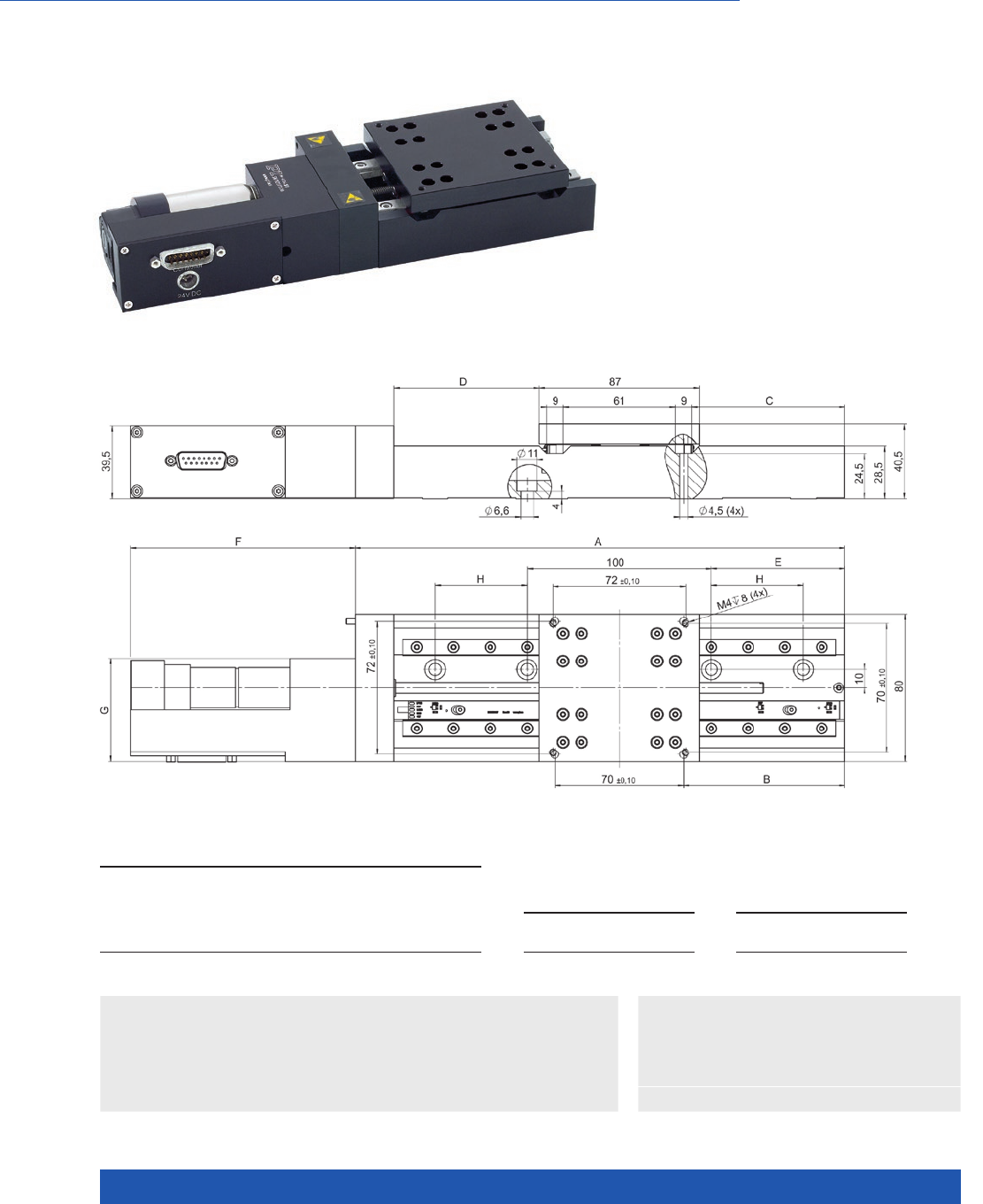
WWW.PI.WS
46
Inexpensive and Flexible Thanks to Large Number of Drives and Travel Range Variants
M-404 Precision Translation Stage
>> ActiveDrive
>> Incremental Encoder
Technology Glossary ...................... page 290
Applications
n Automation
n Biotechnology
n Medical Industry
n Photonics
n Inexpensive cost-optimized design for
precise positioning
n Travel ranges from 25 mm to 200 mm
n Resolution to 0.012 µm
n Min. incremental motion to 0.1 µm
n Ball screw for high velocities and number
of cycles
n M-413 and M-414 versions for higher load
requirements
M-403 and M-404, dimensions in mm
M-403.xPD M-403.xDG
F
G
114
59,5
119,5
56
M-404.xPD M-403.xDG
F
G
114
59,5
128,5
56
M- 403.1x x
M- 404.1x x
M-403.2xx
M-404.2xx
M-403.4x
M-404.4xx
M-403.6xx
M-404.6xx
M-403.8xx
M-404.8xx
A
B
C
D
E
H
141
25
20,5
16,5 (±12,5)
10
X
166
37,5
33
29 (±25)
22,5
X
216
62,5
58
54 (±50)
47, 5
X
266
87,5
83
79 (±75)
72,5
50
316
112,5
108
104 (±100)
97, 5
75

MOTION | POSITIONING
47
M-404.1PD
M-404.2PD
M-404.4PD
M-404.6PD
M-404.8PD
M-404.1DG
M-404.2DG
M-404.4DG
M-404.6DG
M-404.8DG
Unit Tolerance
with ActiveDrive with DC gear motor
Motion and positioning
Travel range 25 / 50 / 100 / 150 / 200 25 / 50 / 100 / 150 / 200 mm
Integrated sensor Rotary encoder Rotary encoder
Sensor resolution 4000 2000 Cts./rev.
Design resolution 0.25 0.012 µm typ.
Minimum incremental motion 0.25 0.1 µm typ.
Backlash 0.5 2 µm typ.
Unidirectional repeatability 0.5 1 µm typ.
Pitch 75 75 µrad typ. over
100 mm
Yaw 75 75 µrad typ. over
100 mm
Velocity 50 1.5 mm/s max.
Reference point switch
repeatability
1 1 µm typ.
Mechanical properties
Drive screw pitch 1 1 mm
Gear ratio – 2704:63
Motor resolution – – steps/rev.
Stiffness in motion direction 3 3 N/µm ±20 %
Load capacity (1) 200 200 N max.
Push/pull force 50 50 N max.
Lateral force 100 100 N max.
Drive properties
Drive type DC motor, ActiveDrive DC gear motor
Operating voltage 24 0 to ±12 V
Motor power 26 2.5 W nominal
Miscellaneous
Operating temperature range –20 to 65 °C –20 to 65 °C
Material Al (black anodized) Al (black anodized)
Mass 1.8 / 1.9 /2.2 / 2.3 /2.6 1.8 / 1.9 /2.2 / 2.3 /2.6 kg ±5 %
Connector Sub-D 15 (m), incl. 3 m cable Sub-D 15 (m), incl. 3 m cable
Recommended controllers /
drivers
C-863
C-884
C-863
C-884
(1) Max. possible normal load capacity, centered, vertical load (linear stage horizontal).
Translation Stages
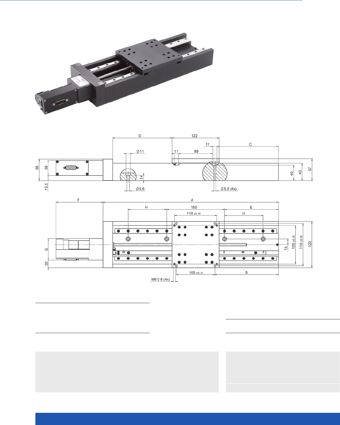
WWW.PI.WS
48
Inexpensive and Flexible Thanks to Large Number of Drives and Travel Range Variants for High Loads
M-413 High-Load Precision Stage
>> ActiveDrive
>> Incremental Encoder
Technology Glossary ...................... page 290
Applications
n Automation
n Biotechnology
n Medical Industry
n Photonics
n Very inexpensive, robust models
n Flexible modular system M-403,
M-404, M-413, M-414
n Travel ranges from 100 to 300 mm
n Resolution to 0.018 µm
n Preloaded precision leadscrew
n Min. incremental motion 0.2 µm
M-413 and M-414, dimensions in mm
M-413/414.1xx M-413/414.2xx M-413/414.3xx
A
B
C
D
E
H
255
65
59,5
54 (±50)
40
X
355
115
109,5
104 (±100)
90
X
455
165
159,5
154 (±150)
140
100
M-413/414.xPD M-413.xDG M-414.xDG
F
G
120
59,5
122
56
133
59,5

MOTION | POSITIONING
49
M-413.1PD
M-413.2PD
M-413.3PD
M-413.1DG
M-413.2DG
M-413.3DG
Unit Tolerance
with ActiveDrive with DC gear motor
Motion and positioning
Travel range 100 / 200 / 300 100 / 200 / 300 mm
Integrated sensor Rotary encoder Rotary encoder
Sensor resolution 4000 2000 Cts./rev.
Design resolution 0.25 0.018 µm typ.
Minimum incremental motion 0.25 0.2 µm typ.
Backlash 6 10 µm typ.
Unidirectional repeatability 1 1 µm typ.
Pitch / yaw (1) 300 300 µrad typ. over
100 mm
Velocity 10 (2) 2.5 mm/s max.
Reference point switch
repeatability
1 1 µm typ.
Mechanical properties
Drive screw pitch 1 1 mm
Gear ratio – 2304:81
Stiffness in motion direction 3.5 3.5 N/µm ±20 %
Load capacity 500 500 N max.
Push/pull force 50 50 N max.
Lateral force 200 200 N max.
Drive properties
Drive type DC motor, ActiveDrive DC gear motor
Operating voltage 24 0 to ±12 V
Motor power 70 3.6 W nominal
Miscellaneous
Operating temperature range –20 to 65 –20 to 65 °C
Material Al (black anodized) Al (black anodized)
Mass 4.4 / 5.4 / 6.6 4.2 / 5.2 / 6.4 kg ±5 %
Connector Sub-D 15 (m), incl. 3 m cable Sub-D 15 (m), incl. 3 m cable
Recommended controllers /
drivers
C-863
C-884
C-863
C-884
(1) This value applies to each 100 mm respectively for travel ranges greater than 100 mm.
(2) Recommended velocity
Translation Stages

WWW.PI.WS
50
Inexpensive and Flexible Thanks to Large Number of Drives and Travel Range Variants for High Loads
M-414 High-Load Precision Stage
>> ActiveDrive
>> Incremental Encoder
Technology Glossary ...................... page 290
Applications
n Automation
n Biotechnology
n Medical Industry
n Photonics
n Use of precision components
n Flexible modular system M-403, M-404,
M-413, M-414
n Travel ranges from 100 mm to 300 mm
n Resolution to 0.023 µm
n Ball screw for high velocities and number
of cycles
n Min. incremental motion 0.1 µm
M-413 and M-414, dimensions in mm
M-413/414.1xx M-413/414.2xx M-413/414.3xx
A
B
C
D
E
H
255
65
59,5
54 (±50)
40
X
355
115
109,5
104 (±100)
90
X
455
165
159,5
154 (±150)
140
100
M-413/414.xPD M-413.xDG M-414.xDG
F
G
120
59,5
122
56
133
59,5

MOTION | POSITIONING
51
M-414.1PD
M-414.2PD
M-414.3PD
M-414.1DG
M-414.2DG
M-414.3DG
Unit Tolerance
with ActiveDrive with DC gear motor
Motion and positioning
Travel range 100 / 200 / 300 100 / 200 / 300 mm
Integrated sensor Rotary encoder Rotary encoder
Sensor resolution 4000 2000 Cts./rev.
Design resolution 0.5 0.023 µm typ.
Minimum incremental motion 0.5 0.1 µm typ.
Backlash 0.5 4 µm typ.
Unidirectional repeatability 0.5 1 µm typ.
Pitch / yaw (1) 100 100 µrad typ. over
100 mm
Velocity 100 3 mm/s max.
Reference point switch
repeatability
1 1 µm typ.
Mechanical properties
Drive screw pitch 2 2 mm
Gear ratio – 42.9206
Stiffness in motion direction 8 8 N/µm ±20 %
Load capacity 500 500 N max.
Push/pull force 100 50 N max.
Lateral force 200 200 N max.
Drive properties
Drive type DC motor, ActiveDrive DC gear motor
Operating voltage 24 0 to ±12 V
Motor power 70 3.6 W nominal
Miscellaneous
Operating temperature range –20 to 65 –20 to 65 °C
Material Al (black anodized) Al (black anodized)
Mass 4.4 / 5.4 / 6.6 4.2 / 5.2 / 6.4 kg ±5 %
Connector Sub-D 15 (m), incl. 3 m cable Sub-D 15 (m), incl. 3 m cable
Recommended controllers /
drivers
C-863
C-884
C-863
C-884
(1) This value applies to each 100 mm respectively for travel ranges greater than 100 mm.
Translation Stages
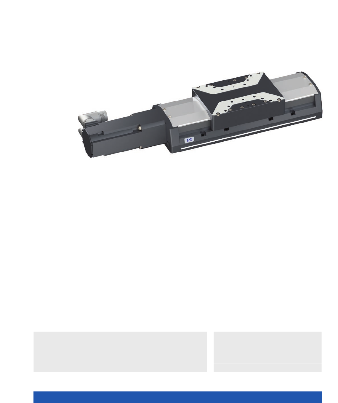
WWW.PI.WS
52
High Performance and Cost Efficiency, Drive Screw
L-412 High-Load Linear Stage
>> Absolute Encoder
>> Incremental Encoder
Technology Glossary ...................... page 290
Applications
n Automated Optical
Inspection (AOI)
n Electronics Manufacturing
n Automation
n Laser Cutting
Class leading design
When compared to current market offerings, the
new L-412 series of stages provides users with a
higher specification recirculating ball bearing that
offers higher load carrying capacity and dynamic
performance. The standard motor offers a high
resolution resulting in improved motion tracking
errors and refined move and settle performance.
Options
n Holding brake (L-412.xxxxxxB)
n Various rotary and linear encoders,
absolute and incremental
n Versions with linear encoder with
optional drag chain and connection box
(L-412.xxxxxxE1) or without drag chain
(L-412.xxxxxxE0)
n Foldback kits to reduce overall length
available on request
n Certification and calibration available
on request
Reference-class linear stage
PI has extended its product portfolio for industrial solutions with a new family
of precision linear ball-screw stages. Various versions are availablewith high-
performance synchronous servo motors, heavy-duty recirculating ball bearings,
and precision rotary and linear encoders. An optional holding brake allows use
as a vertical axis. The stage’s internal ball screw can be relubricated externally
thus removing the need to disassemble the stage. This provides a higher relia-
bility and longer lifetime when compared to stages requiring additional effort in
relubrication. It is also possible to integrate such lubrication into a customer‘s
central lubrication system. The protective side seal and the purge air connection
prevent contamination by debris entering the stage.
Synchronous servo motor
These motors have high positioning accuracy and overload capacity over a
large rotation speed range. High torque and low inertia ensure high dynamic
operation of the stage. The motor provides an adaptable cable exit, allowing the
user to be flexible with their cable positioning strategies in their machine. The
long lifetime, high performance and robustness of these servo motors produce
excellent results in applications in precision industrial automation.
n Width 116 mm
n Travel range to 610 mm
n Precision ball screw
n Incremental or absolute rotary encoder options
n Additional linear encoder options
n Precision recirculating ball bearings, load capacity to 400 N
n Covering strip on the side for protection against debris

MOTION | POSITIONING
53
L-412.03 L-412.05 L-412.09 L-412.13 Unit Tolerance
Motion
Travel range 52 102 204 305 mm
Pitch / yaw ±9 ±14 ±19 ±29 µrad max.
Straightness / flatness ±1.5 ±2.5 ±4 ±6 µm max.
Velocity, unloaded 300 300 300 300 mm/s max.
Positioning accuracy
(uncalibrated)
±5 ±6 ±8 ±10 µm max.
L-412.17 L-412.21 L-412.25 Unit Tolerance
Motion
Active axes X X X
Travel range 407 508 610 mm
Pitch / yaw ±39 ±48 ±58 µrad max.
Straightness / flatness ±8 ±9 ±10 µm max.
Velocity, unloaded 300 300 300 mm/s max.
Positioning accuracy
(uncalibrated)
±12 ±14 ±16 µm max.
L-412.xxx232
basic option
L-412.xxx244 L-412.xxx054 Unit Tolerance
Encoder options
Integrated sensor Incremental rotary
encoder
Absolute rotary
encoder, single turn
Absolute rotary
encoder, multiturn
Sensor signal A/B quadrature, RS-422 EnDat 2.1 EnDat 2.1
Sensor resolution 20000 8192 8192 Cts./rev.
Design resolution 0.25 0.6 0.6 µm
Minimum incremental
motion
122µm
Bidirectional repeata-
bility
±1 ±3 ±3 µm max.
Limit switches Hall effect, 5 V NPN Hall effect, 5 V NPN –
Sensor connection M23 M23 M23
L-412.xxx212Ex L-412.xxx211Ex L-412.xxx025Ex Unit Tolerance
Encoder options
Integrated sensor Incremental linear
encoder
Additional rotary
encoder, see basic
option
Incremental linear
encoder
Additional rotary
encoder, see basic
option
Absolute-measuring
linear encoder
Additional rotary
encoder, see basic
option
Sensor signal A/B quadrature, RS-422 Sin/cos, 1 V peak-peak,
20 µm signal period
EnDat 2.2
Design resolution 0.05 – 0.001 µm
Minimum incremental
motion
300 50 50 nm typ.
Bidirectional
repeatability
±0.5 ±0.5 ±0.5 µm max.
Limit switches Hall effect, 5 V NPN Hall effect, 5 V NPN –
Sensor connection Sub-D 15 (m) M17 M17
Translation Stages

WWW.PI.WS
54
L-412.xx9 Unit Tolerance
Drive properties
Drive type Synchronous servo motor
Intermediate circuit
voltage, effective
320 V DC max.
Peak torque 2.76 N·m typ.
Nominal torque 0.7 N·m typ.
Peak current,
effective (RMS)
10.9 A typ.
Nominal current,
effective (RMS)
2.2 A typ.
Torque constant,
effective
0.32 N·m/A typ.
Resistance phase-phase 5.22 Ω typ.
Inductance phase-phase 9.7 mH typ.
Back EMF phase-phase 20.4 V/kRPM max.
Number of pole pairs 3
Connecting cables are not in the scope of delivery and must be ordered separately.
Ask about custom designs!
L-412 Unit Tolerance
Miscellaneous
Material Aluminum, black anodized stainless steel
Overall mass L-412.03 (52 mm travel range): 6.4
L-412.05 (102 mm travel range): 6.9
L-412.09 (204 mm travel range): 7.9
L-412.13 (305 mm travel range): 8.9
L-412.17 (407 mm travel range): 9.8
L-412.21 (508 mm travel range): 10.8
L-412.25 (610 mm travel range): 11.8
kg ±5 %
Moved mass 1.4 kg ±5 %
MTBF 20000 h
Connection M23 (motor)
M23 (rotary encoder)
optional connection for linear encoder
Fitting for purge air hose with outside diameter 4 mm
Funnel-type grease nipple for spindle lubrication
Limit switch connection M8 8-pin
Recommended
controllers
ACS modular controller
L-412.xxxxxx L-412.xxxxxxB Unit Tolerance
Mechanical properties
Guide type Recirculating ball bearing Recirculating ball bearing
Drive screw type Ball screw Ball screw
Holding brake – Electromagnetic safety brake
Drive screw pitch 5 5 mm
Push/pull force,
power on
700 700 N max.
Holding force, power off – 500 N typ.
Load capacity in Z 400 400 N max.
Permissible lateral force 200 200 N max.
Permissible torque in θX20 20 N·m max.
Permissible torque in θY15 15 N·m max.
Permissible torque in θZ20 20 N·m max.
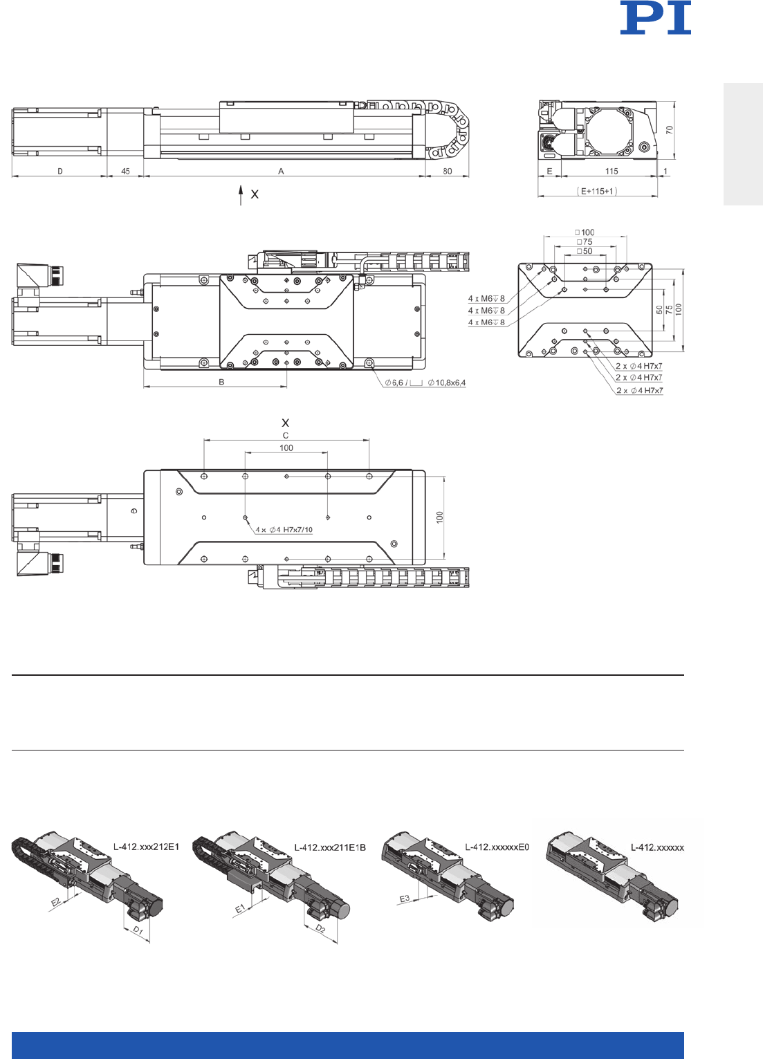
MOTION | POSITIONING
55
TRAVEL A B C D E
D1
L-412.xxxxxxxx
D2
L-412.xxxxxxxxB
E1
L-412.xxxxxxEO
E2
L-412.xxx211E1
E3
L-412.xxx212E1
L-417.03xxxx
L-417.05xxxx
L-417.09xxxx
L-417.13xxxx
L-417.17xxxx
L-417.21xxxx
L-417.25xxxx
52 (4”)
102 (4”)
204 (8”)
305 (12”)
407 (16”)
508 (20”)
610 (24”)
290
340
445
545
645
745
850
147, 5
172,5
225
275
325
375
42 7, 5
100
100, 200
100, 200, 300
100, 200, 300, 400
100, 200, 300, 400, 500
100, 200, 300, 400, 500, 600
100, 200, 300, 400, 500, 600, 700
114,5
114,5
114,5
114,5
114,5
114,5
114,5
148,5
148,5
148,5
148,5
148,5
148,5
148,5
44
44
44
44
44
44
44
28,5
28,5
28,5
28,5
28,5
28,5
28,5
28
28
28
28
28
28
28
L-412, dimensions in mm
Translation Stages
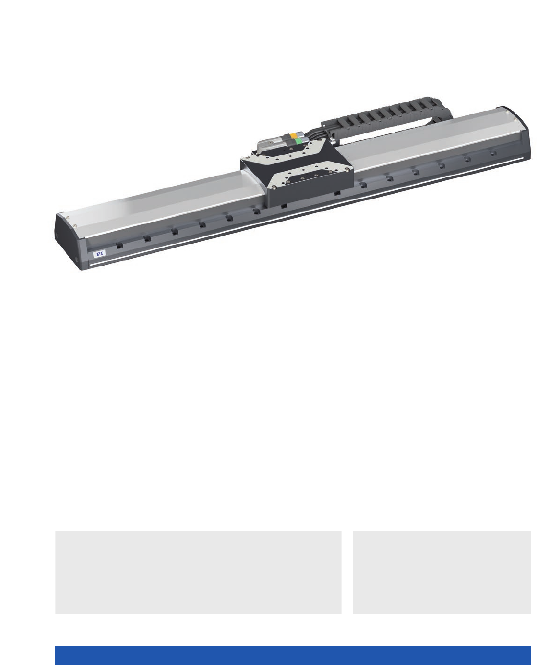
WWW.PI.WS
56
High Performance and Cost Efficiency, Linear Motor
V-412 PIMag® High-Load Linear Stage
>> Absolute Encoder
>> Linear Encoder
>> PIMag® Magnetic Linear Motors
Technology Glossary ...................... page 290
Applications
n Automated Optical
Inspection (AOI)
n Digital Printing
n Electronics Manufacturing
n Flatpanel Inspection
n Automation
n Laser Cutting
n Scanning
n Width 116 mm
n Travel range to 610 mm
n Nominal force 33 N
n Incremental or absolute linear encoder
n Precision recirculating ball bearings,
load capacity to 400 N
n Covering strip on the side for protection
against debris
Class leading design
When compared to current market offerings, the
new V-412 series of stages provides users with a
higher specification recirculating ball bearing that
offers higher load carrying capacity and dynamic
performance. The encoder options offer a high
resolution resulting in improved motion tracking
errors and refined move and settle performance.
For full flexibility the user can select either incre-
mental or absolute types. Absolute types remove
the requirement to home the stage during startup
and provide additional benefits including reduced
collision risks during operation.
Reference-class linear stage
PI has extended its product portfolio for industrial solutions with a new family
of precision linear motor stages. Various versions are available with high-per-
formance linear motors, heavy-duty recirculating ball bearings, and precision
linear encoders. The protective side seal and the purge air connection prevent
contamination by debris entering the stage.
PIMag® magnetic direct drive
3-phase magnetic direct drives do not use mechanical components in the drive-
train, they transmit the drive force to the motion platform directly and without
friction. The ironless linear motors reach high velocities and accelerations.
Ironless motors are particularly suitable for positioning tasks with the highest
demands on precision because there is no undesirable interaction with the
permanent magnets. This is in comparison to iron core linear motors which
exhibit ‘cogging’. This allows smooth running even at low velocities and no
vibration at high velocities.

MOTION | POSITIONING
57
V-412.03 V-412.05 V-412.09 V-412.13 Unit Tolerance
Motion
Travel range 52 102 204 305 mm
Pitch / yaw ±9 ±14 ±19 ±29 µrad max.
Straightness / flatness ±1.5 ±2.5 ±4 ±6 µm max.
Velocity, unloaded 2000 2000 2000 2000 mm/s max.
Positioning accuracy
(uncalibrated)
±3 ±4 ±8 ±10 µm typ.
V-412.17 V-412.21 V-412.25 Unit Tolerance
Motion
Active axes X X X
Travel range 407 508 610 mm
Pitch / yaw ±39 ±48 ±58 µrad max.
Straightness / flatness ±8 ±9 ±10 µm max.
Velocity, unloaded 2000 2000 2000 mm/s max.
Positioning accuracy
(uncalibrated)
±12 ±14 ±15 µm typ.
V-412.xxx211Ex V-412.xxx025Ex Unit Tolerance
Encoder options
Integrated sensor Incremental linear encoder Absolute-measuring linear encoder
Sensor signal Sin/cos, 1 V peak-peak,
20 µm signal period
EnDat 2.2
Design resolution 0.0003 0.001 µm
Minimum incremental
motion
510 nm typ.
Bidirectional
repeatability
±0.5 ±0.5 µm typ.
Limit switches Hall effect, 5 V NPN –
V-412.xxxxxx V-412.xxxxxxB Unit Tolerance
Mechanical properties
Guide type Recirculating ball bearing Recirculating ball bearing
Load capacity in Z 400 400 N max.
Permissible lateral force 200 200 N max.
Permissible torque in θX20 20 N·m max.
Permissible torque in θY15 15 N·m max.
Permissible torque in θZ20 20 N·m max.
Translation Stages

WWW.PI.WS
58
V-412.xx6 Unit Tolerance
Drive properties
Drive type Ironless 3-phase linear motor
Intermediate circuit
voltage, effective
300 V DC max.
Peak force 151 N typ.
Nominal force 33 N typ.
Peak current,
effective (RMS)
10.6 A typ.
Nominal current,
effective (RMS)
2.3 A typ.
Force constant, effective 14.1 N/A typ.
Motor constant 4 N/√W typ.
Electrical time constant 0.19 ms
Resistance phase-phase 8.69 Ω typ.
Inductance phase-phase 1.4 mH typ.
Back EMF phase-phase 8.1 V·s/m max.
Pole pitch N-N 30.5 mm
V-412 Unit Tolerance
Miscellaneous
Material Aluminum, black anodized
stainless steel
Overall mass V-412.03 (52 mm travel range): 5.0
V-412.05 (102 mm travel range): 5.6
V-412.09 (204 mm travel range): 6.7
V-412.13 (305 mm travel range): 7.9
V-412.17 (407 mm travel range): 9.0
V-412.21 (508 mm travel range): 10.2
V-412.25 (610 mm travel range): 11.3
kg ±5 %
Moved mass 1.7 kg ±5 %
MTBF 20000 h
Connection M17 (motor)
M17 (linear encoder)
Fitting for purge air hose with outside diameter 4 mm
Recommended
controllers
C-891 (single axis)
C-885 with C-891.10C885 (up to 20 axes)
ACS modular controller
Connecting cables are not in the scope of delivery and must be ordered separately.
Ask about custom designs!
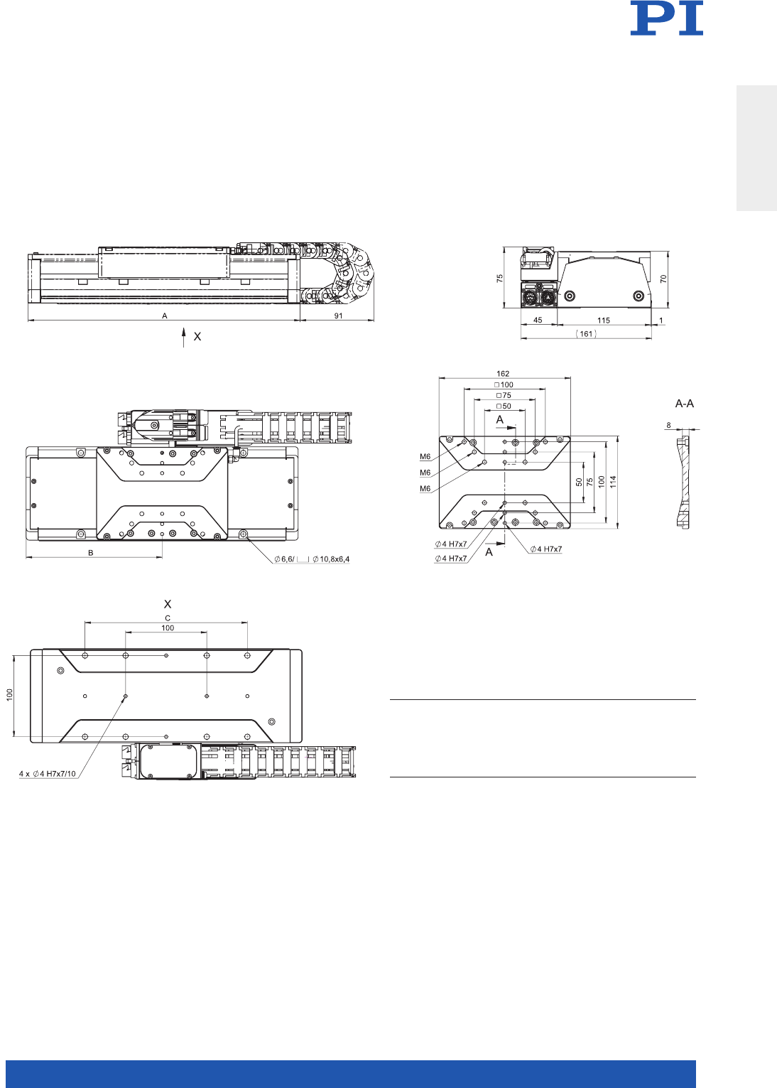
MOTION | POSITIONING
59
V-412, dimensions in mm
TRAVEL A B C
V-412.03xxxx
V-412.05xxxx
V-412.09xxxx
V-412.13xxxx
V-412.17xxxx
V-412.21xxxx
V-412.25xxxx
52 (2”)
102 (4”)
204 (8”)
305 (12”)
407 (16”)
508 (20”)
610 (24”)
285
335
440
540
640
740
845
142,5
167,5
220
270
320
370
422,5
100
100, 200
100, 200, 300
100, 200, 300, 400
100, 200, 300, 400, 500
100, 200, 300, 400, 500, 600
100, 200, 300, 400, 500, 600, 700
Translation Stages
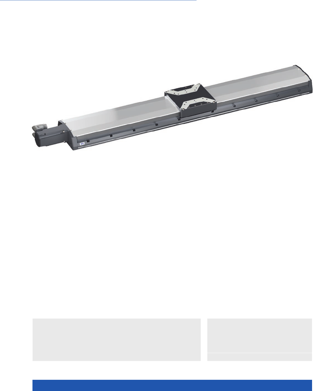
WWW.PI.WS
60
High Performance and Cost Efficiency, Drive Screw
L-417 High-Load Linear Stage
>> Absolute Encoder
>> Incremental Encoder
Technology Glossary ...................... page 290
Applications
n Automated Optical Inspection
(AOI)
n Electronics Manufacturing
n Automation
n Laser Cutting
n Width 166 mm
n Travel range to 813 mm
n Precision ball screw
n Incremental or absolute rotary encoder options
n Additional linear encoder options
n Precision recirculating ball bearings, load capacity to 450 N
n Covering strip on the side for protection against debris
Options
n Holding brake (L-417.xxxxxxB)
n Various rotary and linear encoders,
absolute and incremental
n Versions with linear encoder with
optional drag chain and connection box
(L-417.xxxxxxE1) or without drag chain
(L-417.xxxxxxE0)
n Foldback kits to reduce overall length
available on request
n Certification and calibration available
on request
Class leading design
When compared to current market offerings, the
new L-417 series of stages provides users with a
higher specification recirculating ball bearing that
offers higher load carrying capacity and dynamic
performance. The standard motor offers a high
resolution resulting in improved motion tracking
errors and refined move and settle performance.
Reference-class linear stage
PI has extended its product portfolio for industrial solutions with a new family
of precision linear ball-screw stages. Various versions are available with high-
performance synchronous servo motors, heavy-duty recirculating ball bearings,
and precision rotary and linear encoders. An optional holding brake allows use
as a vertical axis. The stage’s internal ball screw can be relubricated externally
thus removing the need to disassemble the stage. This provides a higher relia-
bility and longer lifetime when compared to stages requiring additional effort in
relubrication. It is also possible to integrate such lubrication into a customer‘s
central lubrication system. The protective side seal and the purge air connection
prevent contamination by debris entering the stage.
Synchronous servo motor
These motors have high positioning accuracy and overload capacity over a
large rotation speed range. High torque and low inertia ensure high dynamic
operation of the stage. The motor provides an adaptable cable exit, allowing the
user to be flexible with their cable positioning strategies in their machine. The
long lifetime, high performance and robustness of these servo motors produce
excellent results in applications in precision industrial automation.

MOTION | POSITIONING
61
L-417.05 L-417.09 L-417.13 L-417.17 Unit Tolerance
Motion
Travel range 102 204 305 407 mm
Pitch / yaw ±14 ±19 ±29 ±35 µrad max.
Straightness / flatness ±2.5 ±4 ±6 ±8 µm max.
Velocity, unloaded 300 300 300 300 mm/s max.
Positioning accuracy
(uncalibrated)
±6 ±8 ±10 ±12 µm max.
L-417.21 L-417.25 L-417.33 Unit Tolerance
Motion
Active axes X X X
Travel range 508 610 813 mm
Pitch / yaw ±40 ±45 ±50 µrad max.
Straightness / flatness ±9 ±10 ±12 µm max.
Velocity, unloaded 300 300 250 mm/s max.
Positioning accuracy
(uncalibrated)
±14 ±16 ±18 µm max.
L-417.xxx232
basic option
L-417.xxx244 L-417.xxx054 Unit Tolerance
Encoder options
Integrated sensor Incremental rotary
encoder
Absolute rotary
encoder, single turn
Absolute rotary
encoder, multiturn
Sensor signal A/B quadrature, RS-422 EnDat 2.1 EnDat 2.1
Sensor resolution 20000 8192 8192 Cts./rev.
Design resolution 0.25 0.6 0.6 µm
Minimum incremental
motion
122µm
Bidirectional
repeatability
±1 ±3 ±3 µm max.
Limit switches Hall effect, 5 V NPN Hall effect, 5 V NPN –
Sensor connection M23 M23 M23
L-417.xxx212Ex L-417.xxx211Ex L-417.xxx025Ex Unit Tolerance
Encoder options
Integrated sensor Incremental linear
encoder
Additional rotary
encoder, see basic
option
Incremental linear
encoder
Additional rotary
encoder, see basic
option
Absolute-measuring
linear encoder
Additional rotary
encoder, see basic
option
Sensor signal A/B quadrature, RS-422 Sin/cos, 1 V peak-peak,
20 µm signal period
EnDat 2.2
Design resolution 0.05 – 0.001 µm
Minimum incremental
motion
300 50 50 nm typ.
Bidirectional
repeatability
±0.5 ±0.5 ±0.5 µm max.
Limit switches Hall effect, 5 V NPN Hall effect, 5 V NPN –
Sensor connection Sub-D 15 (m) M17 M17
Translation Stages

WWW.PI.WS
62
L-417.xxxxxx L-417.xxxxxxB Unit Tolerance
Mechanical properties
Guide type Recirculating ball bearing Recirculating ball bearing
Drive screw type Ball screw Ball screw
Holding brake – Electromagnetic safety brake
Drive screw pitch 5 5 mm
Push/pull force,
power on
700 700 N max.
Holding force, power off – 500 N typ.
Load capacity in Z 450 450 N max.
Permissible lateral force 250 250 N max.
Permissible torque in θX40 40 N·m max.
Permissible torque in θY30 30 N·m max.
Permissible torque in θZ40 40 N·m max.
L-417.xx9 Unit Tolerance
Drive properties
Drive type Synchronous servo motor
Intermediate circuit
voltage, effective
320 V DC max.
Peak torque 2.76 N·m typ.
Nominal torque 0.7 N·m typ.
Peak current,
effective (RMS)
10.9 A typ.
Nominal current,
effective (RMS)
2.2 A typ.
Torque constant,
effective
0.32 N·m/A typ.
Resistance phase-phase 5.22 Ω typ.
Inductance phase-phase 9.7 mH typ.
Back EMF phase-phase 20.4 V/kRPM max.
Number of pole pairs 3
L-417 Unit Tolerance
Miscellaneous
Material Aluminum, black anodized
stainless steel
Overall mass L-417.05 (102 mm travel range): 9.3
L-417.09 (204 mm travel range): 10.8
L-417.13 (305 mm travel range): 12.2
L-417.17 (407 mm travel range): 13.7
L-417.21 (508 mm travel range): 15.1
L-417.25 (610 mm travel range): 16.5
L-417.33 (813 mm travel range): 19.4
kg ±5 %
Moved mass 2.4 kg ±5 %
MTBF 20000 h
Connection M23 (motor)
M23 (rotary encoder)
optional connection for linear encoder
Fitting for purge air hose with outside diameter 4 mm
Funnel-type grease nipple for spindle lubrication
Limit switch connection M8 8-pin
Recommended
controllers
ACS modular controller
Connecting cables are not in the scope of delivery and must be ordered separately.
Ask about custom designs!
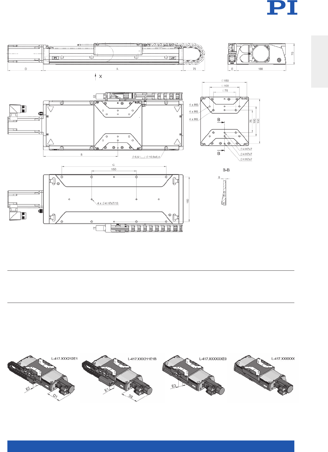
MOTION | POSITIONING
63
L-417, dimensions in mm
TRAVEL A B C D E
D1
L-417.xxxxxxxx
D2
L-417.xxxxxxxxB
E1
L-417.xxxxxxEO
E2
L- 417. x x x211E1
E3
L-417.xxx212E1
L-417.05xxxx
L-417.09xxxx
L-417.13xxxx
L-417.17xxxx
L-417.21xxxx
L-417.25xxxx
L-417.33xxxx
102 (4”)
204 (8”)
305 (12”)
407 (16”)
508 (20”)
610 (24”)
813 (32”)
356
470
570
670
775
875
1080
198
250,5
300,5
350,5
403
453
555,5
150
150, 350
150, 350
150, 350, 550
150, 350, 550
150, 350, 550, 750
150, 350, 550, 750, 950
119,5
119,5
119,5
119,5
119,5
119,5
119,5
153,5
153,5
153,5
153,5
153,5
153,5
153,5
44
44
44
44
44
44
44
28,5
28,5
28,5
28,5
28,5
28,5
28,5
28
28
28
28
28
28
28
Translation Stages
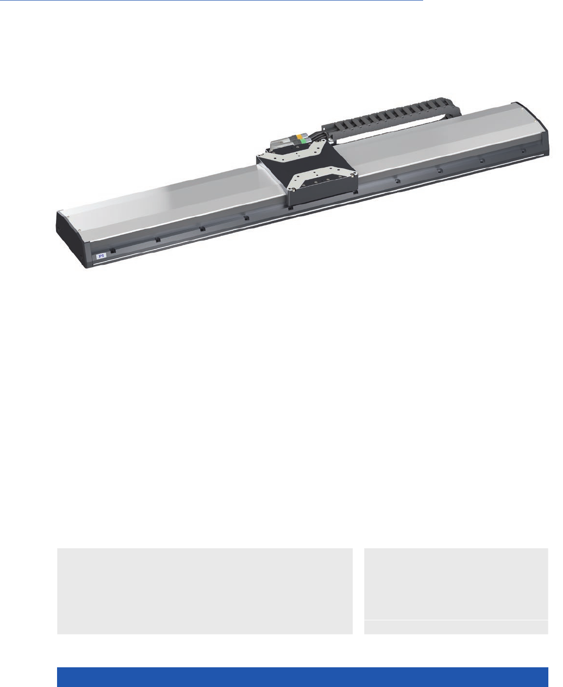
WWW.PI.WS
64
High Performance and Cost Efficiency, Linear Motor
V-417 PIMag® High-Load Linear Stage
>> Absolute Encoder
>> Linear Encoder
>> PIMag® Magnetic Linear Motors
Technology Glossary ...................... page 290
Applications
n Automated Optical
Inspection (AOI)
n Digital Printing
n Electronics Manufacturing
n Flatpanel Inspection
n Automation
n Laser Cutting
n Scanning
Class leading design
When compared to current market offerings, the
new V-417 series of stages provides users with a
higher specification recirculating ball bearing that
offers higher load carrying capacity and dynamic
performance. The encoder options offer a high
resolution resulting in improved motion tracking
errors and refined move and settle performance.
For full flexibility the user can select either incre-
mental or absolute types. Absolute types remove
the requirement to home the stage during startup
and provide additional benefits including reduced
collision risks during operation.
Reference-class linear stage
PI has extended its product portfolio for industrial solutions with a new family
of precision linear motor stages. Various versions are available with high-per-
formance linear motors, heavy-duty recirculating ball bearings, and precision
linear encoders. The protective side seal and the purge air connection prevent
contamination by debris entering the stage.
PIMag® magnetic direct drive
3-phase magnetic direct drives do not use mechanical components in the drive-
train, they transmit the drive force to the motion platform directly and without
friction. The ironless linear motors reach high velocities and accelerations.
Ironless motors are particularly suitable for positioning tasks with the highest
demands on precision because there is no undesirable interaction with the
permanent magnets. This is in comparison to iron core linear motors which
exhibit ‘cogging’. This allows smooth running even at low velocities and no
vibration at high velocities.
n Width 166 mm
n Travel range to 813 mm
n Nominal force 87 N
n Incremental or absolute linear encoder
n Precision recirculating ball bearings, load
capacity to 450 N
n Covering strip on the side for protection
against debris

MOTION | POSITIONING
65
V-417.05 V-417.09 V-417.13 V-417.17 Unit Tolerance
Motion
Travel range 102 204 305 407 mm
Pitch / yaw ±14 ±19 ±29 ±39 µrad max.
Straightness / flatness ±2.5 ±4 ±6 ±8 µm max.
Velocity, unloaded 2000 2000 2000 2000 mm/s max.
Positioning accuracy
(uncalibrated)
±4 ±8 ±10 ±12 µm typ.
V-417.21 V-417.25 V-417.33 Unit Tolerance
Motion
Active axes X X X
Travel range 508 610 813 mm
Pitch / yaw ±40 ±45 ±50 µrad max.
Straightness / flatness ±9 ±10 ±12 µm max.
Velocity, unloaded 2000 2000 2000 mm/s max.
Positioning accuracy
(uncalibrated)
±14 ±15 ±17 µm typ.
V-417.xxxxxx V-417.xxxxxxB Unit Tolerance
Mechanical properties
Guide type Recirculating ball bearing Recirculating ball bearing
Load capacity in Z 450 450 N max.
Permissible lateral force 250 250 N max.
Permissible torque in θX40 40 N·m max.
Permissible torque in θY30 30 N·m max.
Permissible torque in θZ40 40 N·m max.
V-417.xxx211Ex V-417.xxx025Ex Unit Tolerance
Encoder options
Integrated sensor Incremental linear encoder Absolute-measuring linear encoder
Sensor signal Sin/cos, 1 V peak-peak,
20 µm signal period
EnDat 2.2
Design resolution 0.0003 0.001 µm
Minimum
incremental motion
510 nm typ.
Bidirectional
repeatability
±0.5 ±0.5 µm typ.
Limit switches Hall effect, 5 V NPN –
Translation Stages

WWW.PI.WS
66
V-417 Unit Tolerance
Miscellaneous
Material Aluminum, black anodized
stainless steel
Overall mass V-417.05 (102 mm travel range): 9.3
V-417.09 (204 mm travel range): 11.2
V-417.13 (305 mm travel range): 13.0
V-417.17 (407 mm travel range): 14.8
V-417.21 (508 mm travel range): 16.6
V-417.25 (610 mm travel range): 18.4
V-417.33 (610 mm travel range): 21.1
kg ±5 %
Moved mass 2.8 kg ±5 %
MTBF 20000 h
Connection M17 (motor)
M17 (linear encoder)
Fitting for purge air hose with outside diameter 4 mm
Recommended
controllers
C-891 (single axis)
C-885 with C-891.10C885 (up to 20 axes)
ACS modular controller
Connecting cables are not in the scope of delivery and must be ordered separately.
Ask about custom designs!
V-417.xx6 Unit Tolerance
Drive properties
Drive type Ironless 3-phase linear motor
Intermediate circuit
voltage, effective
300 V DC max.
Peak force 300 N typ.
Nominal force 87 N typ.
Peak current,
effective (RMS)
15 A typ.
Nominal current,
effective (RMS)
4.4 A typ.
Force constant, effective 19.9 N/A typ.
Motor constant 8.4 N/√W typ.
Electrical time constant 0.35 ms
Resistance phase-phase 3.6 Ω typ.
Inductance phase-phase 1.2 mH typ.
Back EMF phase-phase 16 V·s/m max.
Pole pitch N-N 30 mm
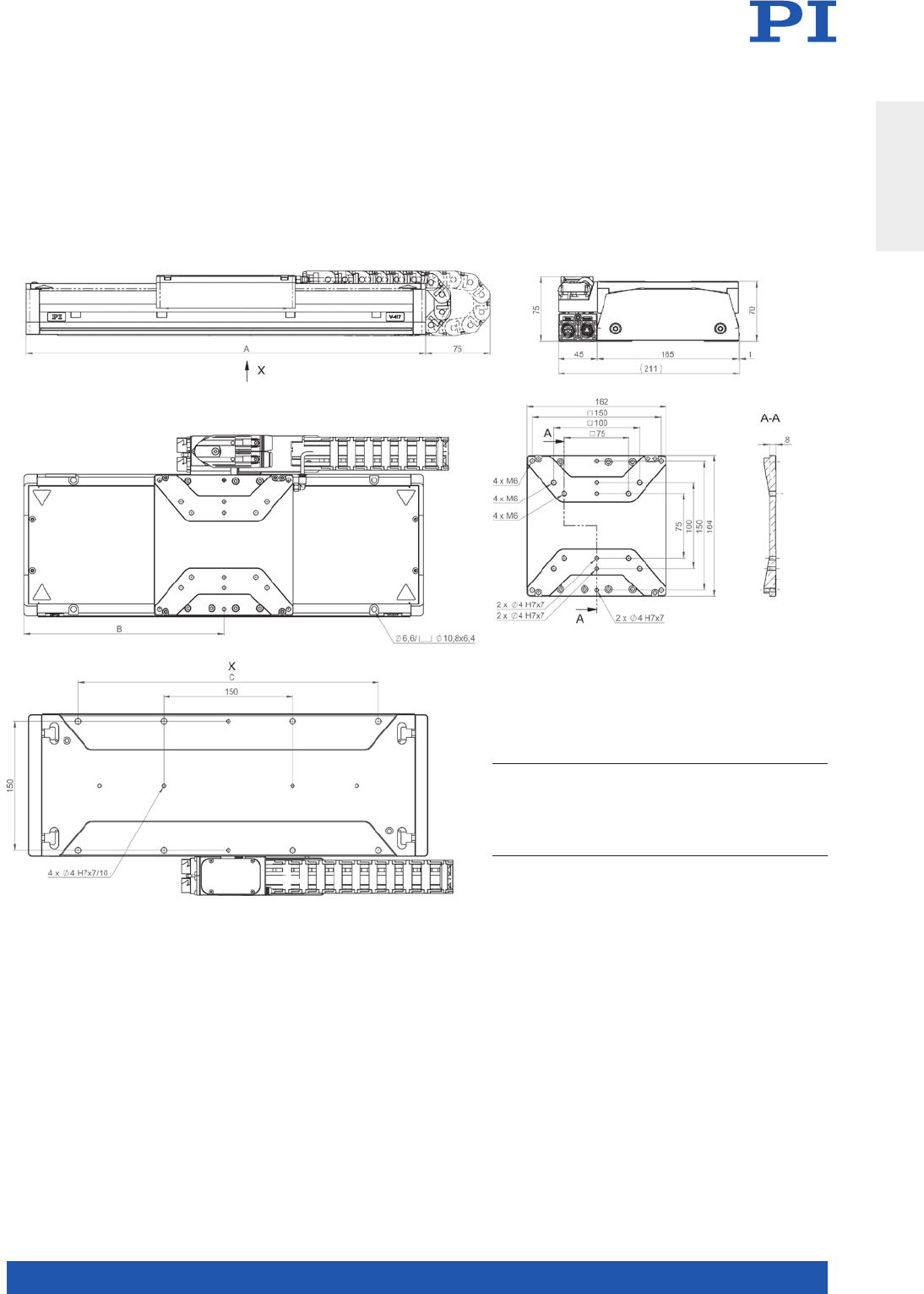
MOTION | POSITIONING
67
V-417, dimensions in mm
TRAVEL A B C
V-417.05XXXX
V-417.09XXXX
V-417.13XXXX
V-417.17XXXX
V-417.21XXXX
V-417.25XXXX
V-417.33XXXX
102 (4”)
204 (8”)
305 (12”)
407 (16”)
508 (20”)
610 (24”)
813 (32”)
360
465
565
665
770
870
1075
180
232,5
282,5
332,5
385
435
537,5
150
150, 350
150, 350
150, 350, 550
150, 350, 550
150, 350, 550, 750
150, 350, 550, 750, 950
Translation Stages
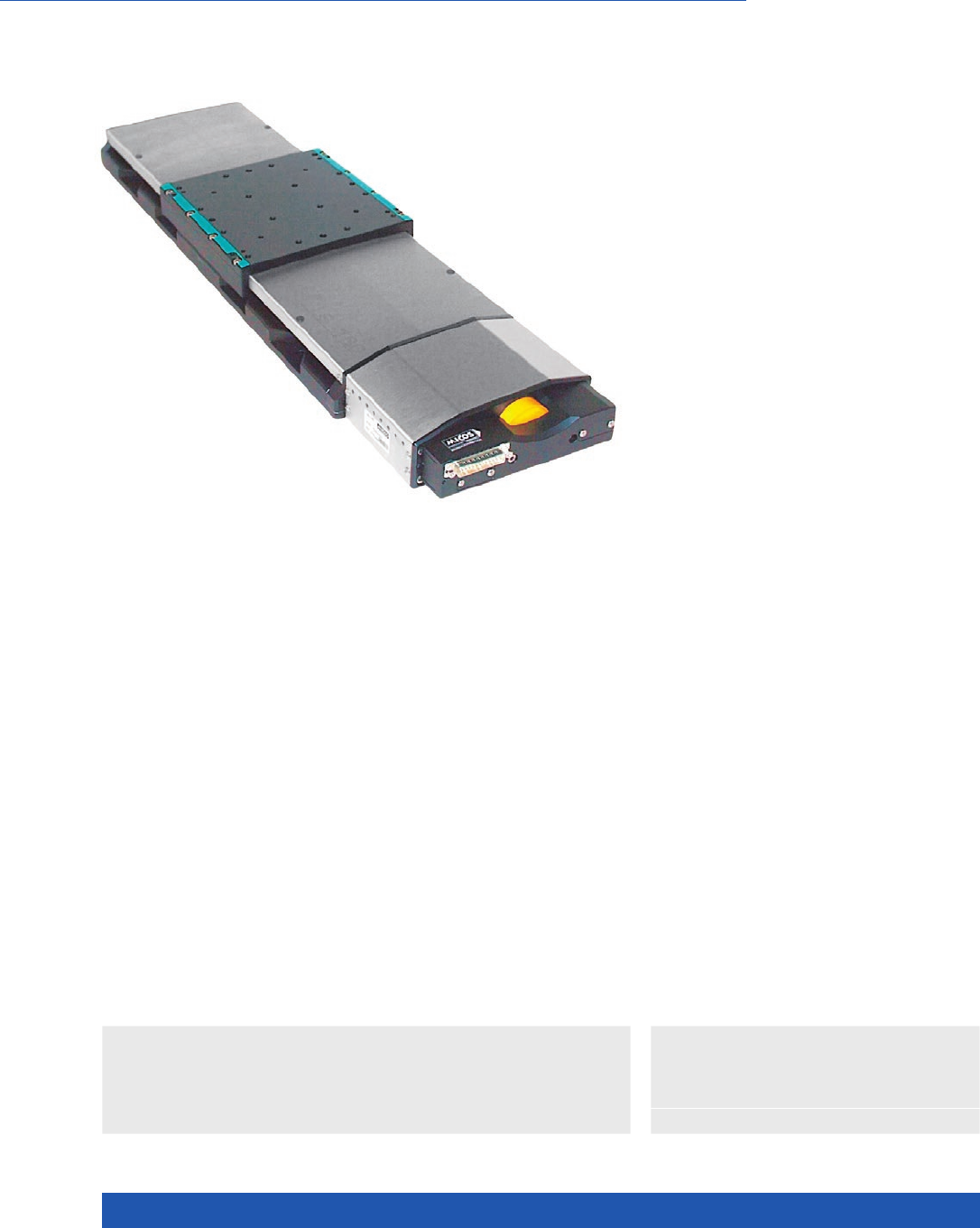
WWW.PI.WS
68
Robust Design for Industrial Use
LS-180 Linear Stage for Heavy Loads
>> Linear Encoder
Technology Glossary ...................... page 290
Applications
n Sample Inspection
n Scanning
n Scientific Instrumentation
n Semiconductor
Drive types
n Closed-loop DC servo motor with rotary
encoder on the motor shaft
n 2-phase stepper motor for high torque
even at low velocities and high resolution
Minimum incremental motion
In conjunction with the SMC Hydra controller,
versions with stepper motor and integrated linear
encoder achieve repeatable minimum incremen-
tal motion in the range of the sensor resolution.
The same configuration achieves constant low
velocities of a few sensor increments per second.
Reference-class linear stage
Recirculating ball bearings for high travel accuracy and load capacity. Precision
ball screw with 5 mm pitch. Stress-relieved aluminum base for highest stability.
Noncontact inductive limit switches.
Highly accurate position measuring with incremental linear encoder
Noncontact optical linear encoders measure the actual position directly at the
motion platform with the greatest accuracy so that nonlinearity, mechanical
play or elastic deformation have no influence on position measuring.
Recirculating ball bearings
When carefully assembled, recirculating ball bearings are distinguished by
a beneficial combination of high load capacity, lifetime, maintenance-free
operation, and guiding accuracy. The moving part of the stages is supported
by four preloaded linear ball bearing units which run on two guide rails. Each
bearing unit is made up of two independent rows of circulating ball bearings.
n Travel ranges from 155 mm to 508 mm
(6” to 20”)
n Max. velocity to 150 mm/s
n Load capacity to 1000 N
n Optional linear encoder for direct
position measurement

MOTION | POSITIONING
69
624091x0 624091x1 624092x0 624092x1-0001 Unit Tolerance
Linear stage with
DC motor and
rotary encoder
Linear stage
with DC motor,
linear and rotary
encoder
Linear stage with
stepper motor
Linear stage
with stepper
motor and linear
encoder
Motion and positioning
Travel range 155 / 205 / 305 /
508
155 / 205 / 305 /
508
155 / 205 / 305 /
508
155 / 205 / 305 /
508
mm
Integrated sensor Rotary encoder Linear and
rotary encoder
– Linear encoder
Sensor signal rotary
encoder
A/B quadrature,
RS-422
A/B quadrature,
RS-422
– –
Sensor signal linear
encoder
– A/B quadrature,
RS-422
– Sin/cos,
1 V peak-peak,
20 µm signal
period
Design resolution 0.25 0.05 25 0.005 µm
Sensor resolution
rotary encoder
20000 20000 – Counts/
rev.
Sensor resolution linear
encoder
– 0.05 – – µm
Minimum incremental
motion
0.5 0.1 0.5 0.1 µm typ.
Unidirectional
repeatability
0.5 0.1 0.5 0.1 µm typ.
Bidirectional
repeatability
±2.5 ±0.1 ±2.5 ±0.1 µm typ.
Pitch ±40 / ±50 / ±60 /
±80
±40 / ±50 / ±60 /
±80
±40 / ±50 / ±60 /
±80
±40 / ±50 / ±60 /
±80
µrad typ.
Yaw ±50 ±50 ±50 ±50 µrad typ.
Straightness ±2 / ±3 / ±4 / ±6 ±2 / ±3 / ±4 / ±6 ±2 / ±3 / ±4 / ±6 ±2 / ±3 / ±4 / ±6 µm typ.
Flatness ±2 / ±3 / ±4 / ±6 ±2 / ±3 / ±4 / ±6 ±2 / ±3 / ±4 / ±6 ±2 / ±3 / ±4 / ±6 µm typ.
Max. velocity 150 150 75 75 mm/s
Mechanical properties
Guide type Recirculating
ball bearing
Recirculating
ball bearing
Recirculating
ball bearing
Recirculating
ball bearing
Drive screw type Ball screw Ball screw Ball screw Ball screw
Drive screw pitch 5 5 5 5 mm
Load capacity 1000 1000 1000 1000 N max.
Push/pull force 800 800 800 800 N max.
Holding force, power off 20 20 50 50 N max.
Permissible lateral force 500 500 500 500 N max.
Permissible torque Mx
in θX
250 250 250 250 N·m max.
Permissible torque My
in θY
132 132 132 132 N·m max.
Permissible torque Mz
in θZ
125 125 125 125 N·m max.
Translation Stages

WWW.PI.WS
70
624091x0 624091x1 624092x0 624092x1-0001 Unit Tolerance
Drive properties
Motor type DC motor DC motor 2-phase stepper
motor
2-phase stepper
motor
Operating voltage,
nominal
24 24 48 48 V nom.
Operating voltage, max. 48 48 48 48 V max.
Peak current, effective 3.8 3.8 2 2 A typ.
Electrical time constant 6 6 ms
Resistance phase-phase 0.62 0.62 2.4 2.4 Ω typ.
Inductance phase-phase 0.13 0.13 2.87 2.87 mH typ.
Back EMF phase-phase 0.00349 0.00349 V/kRPM max.
Step resolution 200 200 Full
steps/
rev.
Limit switches Inductive Inductive Inductive Inductive
Miscellaneous
Operating temperature
range
5 to 40 5 to 40 5 to 40 0 to 55 °C
Material Aluminum, steel Aluminum, steel Aluminum, steel Aluminum, steel
Mass 7.8 / 8.4 / 9.4 /
10.6
8.5 / 9.1 / 10.3 /
11. 5
8.3 / 8.9 / 9.9 /
11. 0
9.0 / 9.6 / 10.8 /
12
kg ±5 %
Moved mass 2.2 2.2 2.2 2.2 kg ±5 %
Connection Sub-D 25 (m) Motor:
Sub-D 25 (m)
Sensor:
Sub-D 9 (m)
Sub-D 25 (m) Motor:
Sub-D 25 (m
Sensor:
Sub-D 9 (m)
Recommended
controllers
C-863
(single axis)
with C-863.AD11
line driver
C-884 (to 6 axes)
with C-863.AD11
line driver
C-885 with
C-863.20C885
(to 40 axes)
and C-863.AD11
line driver
ACS modular
controller
C-863
(single axis)
with C-863.AD11
line driver
C-884 (to 6 axes)
with C-863.AD11
line driver
C-885 with
C-863.20C885
(to 40 axes)
and C-863.AD11
line driver
ACS modular
controller
C-663.12
(single axis)
SMC Hydra
(double axis)
C-885 with
C-663.12C885
(up to 20 axes)
ACS modular
controller
C-663.12
(single axis)
SMC Hydra
(double axis)
C-885 with
C-663.12C885
(up to 20 axes)
ACS modular
controller
Ask about custom designs!
Connecting cables for motor and sensor are not in the scope of delivery and must be ordered separately.
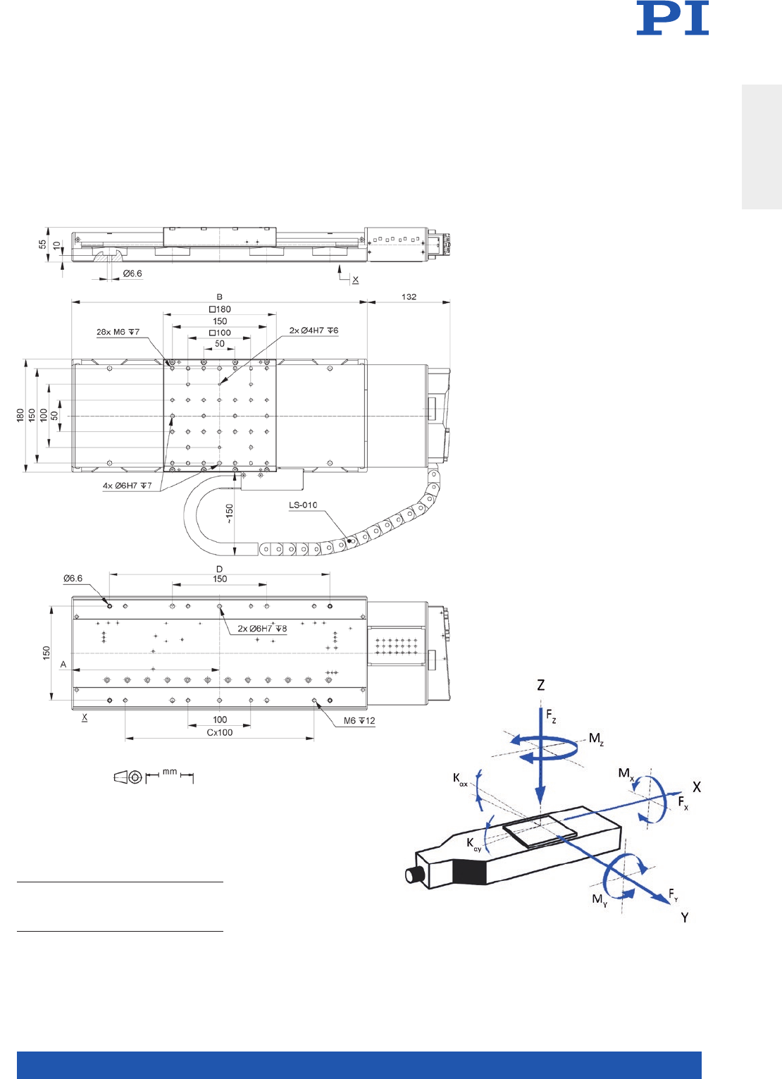
MOTION | POSITIONING
71
LS-180, dimensions in mm, LS-010: Cable for linear encoder
Travel range/mm A B C D
155
205
305
508
235
260
310
410
470
520
620
820
3
3
5
5
350
350
450
650 Direction of the axes
and torques for linear stages
Translation Stages
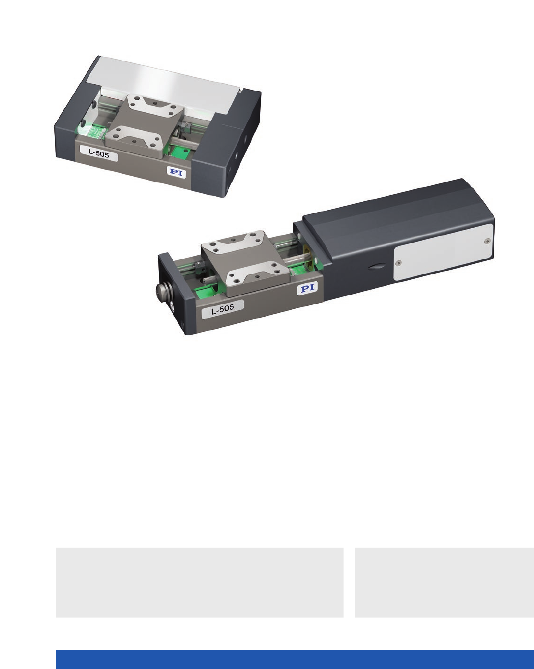
WWW.PI.WS
72
With DC or Stepper Motor
L-505 Compact Linear Stage
>> Linear Encoder
Technology Glossary ...................... page 290
Applications
n Autofocus
n Biotechnology
n Automation
n Medical Industry
n Precision Micro Assembly
Variants with DC motor are equipped with an
incremental linear encoder. This is optional in
the case of stepper motor variants.
Highly accurate position measuring with
incremental linear encoder
Noncontact optical linear encoders measure the
actual position directly at the motion platform
with the greatest accuracy so that nonlinearity,
mechanical play or elastic deformation have no
influence on position measuring.
Product overview
Compact linear stage with low-backlash fine-threaded leadscrews and ball
guides. Directly mountable XY combination. Integrated reference point and
limit switches: Hall effect.
The linear stage is available in two design variants:
n Narrow, long variant with direct fixed drive (flange motor).
n Wide, compact variant with belt drive (folded drivetrain).
These variants are marked by an “F” at the end of the item number.
Drive types
n DC motor with or without gearhead
n Stepper motor with or without gearhead
n Travel ranges 13 or 26 mm
n Stepper motor or DC servo motor with
and without gearhead
n Velocity to 15 mm/s
n Load capacity to 30 N
n Integrated reference point and limit switch

MOTION | POSITIONING
73
L-505 with DC motor L-505.013212
L-505.013212F
L-505.023212
L-505.023212F
L-505.014212F
L-505.024212F
Unit Tolerance
Linear stage with DC motor
and linear encoder
Linear stage with DC gear motor
and linear encoder
Active axes X X
Motion and positioning
Travel range 13 / 26 13 / 26 mm
Integrated sensor Incremental linear encoder Incremental linear encoder
Sensor signal linear
encoder
A/B quadrature, RS-422 A/B quadrature, RS-422
Design resolution 0.05 0.05 µm
Sensor resolution linear
encoder
0.05 0.05 µm
Minimum incremental
motion
0.1 0.5 µm typ.
Unidirectional
repeatability
0.1 0.25 µm typ.
Bidirectional
repeatability
±0.15 ±0.25 µm typ.
Pitch / yaw ±50 / ±75 ±50 / ±75 µrad typ.
Straightness / flatness ±0.5 / ±1 ±0.5 / ±1 µm typ.
Max. velocity L-505.xxxxxx: 15
L-505.xxxxxxF: 7.5
1 mm/s
Reference and limit
switches
Hall effect Hall effect
Reference point switch
repeatability
<4 <4 µm typ.
Mechanical properties
Guide type Ball guide Ball guide
Drive screw type Leadscrew Leadscrew
Drive screw pitch 0.5 0.5 mm
Load capacity 30 30 N max.
Permissible lateral force 30 30 N max.
Push/pull force 20 20 N max.
Holding force, power off 20 20 N typ.
Permissible torque Mx
in θX
L-505.01: 7
L-505.02: 9
L-505.01: 7
L-505.02: 9
N·m max.
Permissible torque My
in θY
L-505.01: 6
L-505.02: 8
L-505.01: 6
L-505.02: 8
N·m max.
Permissible torque Mz
in θZ
L-505.01: 6
L-505.02: 8
L-505.01: 6
L-505.02: 8
N·m max.
Drive properties
Motor type DC motor DC gear motor
Operating voltage,
nominal
24 12 V nom.
Operating voltage, max. 48 24 V max.
Miscellaneous
Operating temperature
range
5 to 40 5 to 40 °C
Material anodized aluminum, stainless steel anodized aluminum, stainless steel
Mass 0.4 0.4 kg ±5 %
Moved mass 0.07 0.07 kg ±5 %
Connection HD Sub-D 26 (m) HD Sub-D 26 (m)
Recommended
controllers
C-863 (single axis)
C-884 (up to 6 axes)
C-885 with C-863.20C885 (to 40 axes)
ACS modular controller
C-863 (single axis)
C-884 (up to 6 axes)
C-885 with C-863.20C885 (to 40 axes)
ACS modular controller
Translation Stages

WWW.PI.WS
74
L-505 with stepper
motor
L-505.011200
L-505.011200F
L-505.021200
L-505.021200F
L-505.011212
L-505.011212F
L-505.021212
L-505.021212F
L-505.01A200F
L-505.02A200F
L-505.01A212F
L-505.02A212F
Unit Tolerance
Linear stage with
stepper motor
Linear stage
with stepper
motor and linear
encoder
Linear stage with
stepper motor
and gearhead
Linear stage with
stepper motor,
gearhead and
linear encoder
Active axes X X
Motion and positioning
Travel range 13 / 26 13 / 26 13 / 26 13 / 26 mm
Integrated sensor – Incremental
linear encoder
– Incremental
linear encoder
Sensor signal linear
encoder
– A/B quadrature,
RS-422
– A/B quadrature,
RS-422
Design resolution 2.5 (full step) 0.005 0.732 (full step) 0.005 µm
Sensor resolution
linear encoder
– 0.005 – 0.005 µm
Minimum incremental
motion
0.1 0.05 0.2 0.05 µm typ.
Unidirectional
repeatability
0.3 0.1 0.3 0.1 µm typ.
Bidirectional
repeatability
±2.5 ±0.15 ±2.5 ±0.15 µm typ.
Pitch / yaw ±50 / ±75 ±50 / ±75 ±50 / ±75 ±50 / ±75 µrad typ.
Straightness / flatness ±0.5 / ±1 ±0.5 / ±1 ±0.5 / ±1 ±0.5 / ±1 µm typ.
Max. velocity L-505.xxxxxx: 10
L-505.xxxxxxF: 7.5
L-505.xxxxxx: 10
L-505.xxxxxxF: 7.5
0.75 0.75 mm/s
Reference and limit
switches
Hall effect Hall effect Hall effect Hall effect
Reference point switch
repeatability
<4 <4 <4 <4 µm typ.
Mechanical properties
Guide type Ball guide Ball guide Ball guide Ball guide
Drive screw type Leadscrew Leadscrew Leadscrew Leadscrew
Drive screw pitch 0.5 0.5 0.5 0.5 mm
Load capacity 30 30 30 30 N max.
Permissible lateral force 30 30 30 30 N max.
Push/pull force 20 20 20 20 N max.
Holding force, power off 20 20 20 20 N typ.
Permissible torque Mx
in θX
L-505.01: 7
L-505.02: 9
L-505.01: 7
L-505.02: 9
L-505.01: 7
L-505.02: 9
L-505.01: 7
L-505.02: 9
N·m max.
Permissible torque My
in θY
L-505.01: 6
L-505.02: 8
L-505.01: 6
L-505.02: 8
L-505.01: 6
L-505.02: 8
L-505.01: 6
L-505.02: 8
N·m max.
Permissible torque Mz
in θZ
L-505.01: 6
L-505.02: 8
L-505.01: 6
L-505.02: 8
L-505.01: 6
L-505.02: 8
L-505.01: 6
L-505.02: 8
N·m max.
Drive properties
Motor type 2-phase stepper
motor
2-phase stepper
motor
2-phase stepper
motor with gear-
head
2-phase stepper
motor with gear-
head
Operating voltage,
nominal
24 24 24 24 V nom.
Operating voltage, max. 48 48 48 48 V max.
Step resolution 200 200 24 24 Full
steps/
rev.
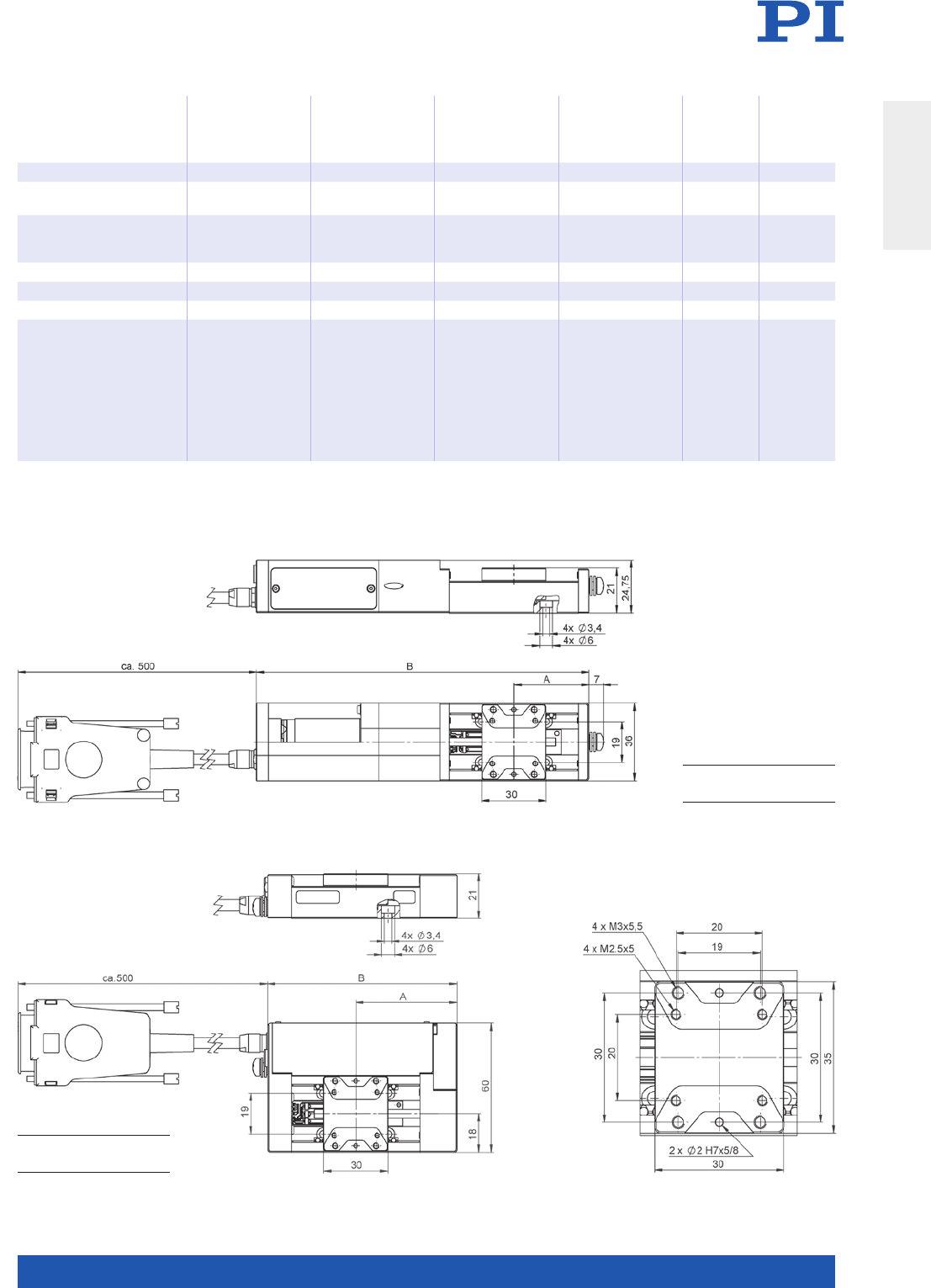
MOTION | POSITIONING
75
All cables required for operation with the ordered controller are included in the scope of delivery.
The cable length is 3 m. Cable for connecting to other controllers can be ordered as accessory.
Custom designs or different specifications on request.
L-505 with stepper motor L-505.011200
L-505.011200F
L-505.021200
L-505.021200F
L-505.011212
L-505.011212F
L-505.021212
L-505.021212F
L-505.01A200F
L-505.02A200F
L-505.01A212F
L-505.02A212F
Unit Tolerance
Miscellaneous
Operating temperature
range
5 to 40 5 to 40 5 to 40 5 to 40 °C
Material anodized
aluminum,
stainless steel
anodized
aluminum,
stainless steel
anodized
aluminum,
stainless steel
anodized
aluminum,
stainless steel
Mass 0.4 0.4 0.4 0.4 kg ±5 %
Moved mass 0.07 0.07 0.07 0.07 kg ±5 %
Connection HD Sub-D 26 (m) HD Sub-D 26 (m) HD Sub-D 26 (m) HD Sub-D 26 (m)
Recommended
controllers
C-663.12
(single axis)
SMC Hydra
(double axis)
C-885 with
C-663.12C885
(up to 20 axes)
ACS modular
controller
C-663.12
(single axis)
SMC Hydra
(double axis)
C-885 with
C-663.12C885
(up to 20 axes)
ACS modular
controller
C-663.12
(single axis)
SMC Hydra
(double axis)
C-885 with
C-663.12C885
(up to 20 axes)
ACS modular
controller
C-663.12
(single axis)
SMC Hydra
(double axis)
C-885 with
C-663.12C885
(up to 20 axes)
ACS modular
controller
Travel range A B
13 mm
26 mm
28.5
35
136
149
L-505.xxxxxxF with belt drive,
dimensions in mm
Travel range A B
13 mm
26 mm
40.5
47
75
88
L-505 motion platform,
dimensions in mm
L-505 with direct fixed drive,
dimensions in mm
Translation Stages
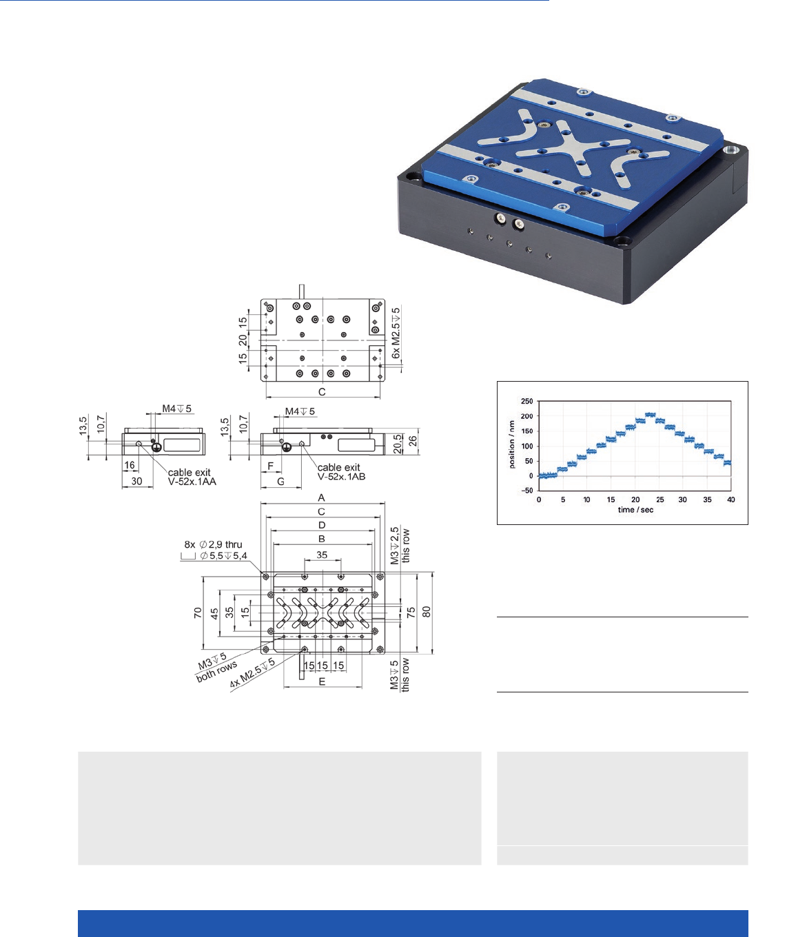
WWW.PI.WS
76
Voice Coil-Direct Drive with Direct Position Measurement
V-522 / V-524 / V-528
High-Dynamics PIMag® Linear Stage
>> Linear Encoder
>> PIMag® Voice Coil
Technology Glossary ...................... page 290
Applications
n Autofocus
n Digital Printing
n Laser Marking
n Metrology / Testing
n Photonics
n Scanning
n Scientific Instrumentation
n Semiconductor
n Fast scanning and positioning
n Travel ranges 5 mm, 10 mm, 20 mm
n Scanning frequencies of more than 10 Hz
n Max. velocity 250 mm/s
n Crossed roller bearings for the highest
precision, anti-creep
The V-522 reliably performs 20-nm repeatable steps
A B C D E F G
V- 52 2.1 A A
V-522.1A B
V- 524 .1A A
V-524.1A B
V- 52 8.1A A
V-528.1AB
80
80
90
90
120
120
65
65
75
75
95
95
70
70
80
80
110
110
70
70
70
70
100
100
–
–
–
–
75
75
–
15
–
15
–
20
–
23
–
25,5
–
39,5
V-52x, dimensions in mm

MOTION | POSITIONING
77
V-522.1AA
V-522.1AB
V-524.1AA
V-524.1AB
V-528.1AA
V-528.1AB
Unit Tolerance
Motion and positioning
Active axes X
Travel range 5 10 20 mm
Integrated Sensor Optical, incremental Optical, incremental Optical, incremental
Sensor resolution 10 10 10 nm
Min. incremental motion 20 20 20 nm typ.
Unidirectional
repeatability
20 20 20 nm
Bidirectional repeatability ±120 ±120 ±120 nm typ.
Reference point
switch repeatability
<1 <1 <1 µm
Pitch ±50 ±50 ±50 µrad max.
Yaw ±50 ±50 ±50 µrad max.
Straightness 0.5 0.5 0.5 µm max.
Flatness 0.5 0.5 0.5 µm max.
Velocity 250 250 250 mm/s max.
Mechanical properties
Load capacity in Z 100 100 100 N max.
Moved mass 131 137 150 g
Overall mass 460 500 580 g
Drive properties
Drive type voice coil voice coil voice coil
Nominal force 4 3.8 2.9 N nominal
Nominal current 1.3 1.3 1. 3 A nominal
Peak current 3 3 3 A max. (3s)
Force constant 3.4 2.9 2.3 N/A typ.
Motor constant 1.3 1.1 0.85 N/(√W) typ.
Coil resistance 7. 2 7. 2 7. 2 Ω typ.
Coil inductance 1.7 1.7 1. 7 mH typ.
Time constant 0.32 0.32 0.32 ms
Miscellaneous
Housing material Aluminum,
black anodized
Aluminum,
black anodized
Aluminum,
black anodized
Cable length 2 2 2 m ±10 mm
Cable exit V-52x.1AA:
cable exit in X
V-52x.1AB:
cable exit in Y
V-52x.1AA:
cable exit in X
V-52x.1AB:
cable exit in Y
V-52x.1AA:
cable exit in X
V-52x.1AB:
cable exit in Y
Voltage / sensor
connection
Sub-D 15 (m) Sub-D 15 (m) Sub-D 15 (m)
Lifetime 20000 20000 20000 km
Operating temperature
range
18 to 45 18 to 45 18 to 45 °C
Relative humidity
during operation
20 to 80 20 to 80 20 to 80 %
Recommended
controllers
C-413 (single axis)
ACS modular controller
C-413 (single axis)
ACS modular controller
C-413 (single axis)
ACS modular controller
Ask about custom designs!
Translation Stages
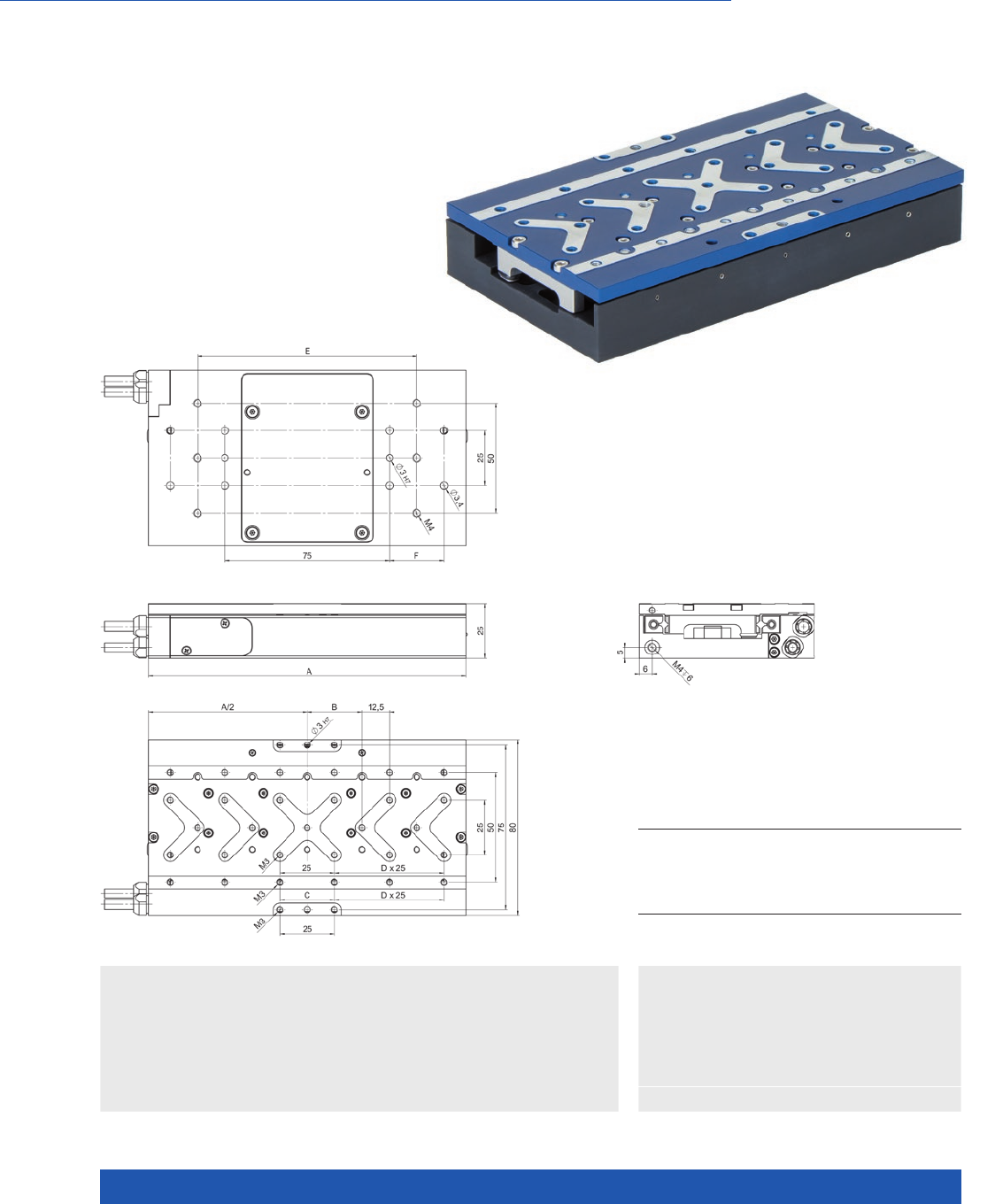
WWW.PI.WS
78
Versatile options for adapting to requirements
V-508 PIMag® Precision Linear Stage
>> Absolute Encoder
>> Linear Encoder
>> PIMag® Magnetic Linear Motors
Technology Glossary ...................... page 290
Applications
n Digital Printing
n Electronics Manufacturing
n Laser Marking
n Medical Industry
n Metrology / Testing
n Scanning
n Travel ranges 80, 170, and 250 mm
n Ironless or iron core linear motor
n Incremental or absolute linear encoder,
various resolutions
n Compact cross section: 80 mm × 25 mm
n Crossed roller bearings for high load
capacity, anti-creep
V-508, dimensions in mm
Travel 80
V-508.3xxxxx
170
V-508.6xxxxx
250
V-508.9xxxxx
A
B
C
D
E
F
145
25
25
2
100
25
235
25
25
4
100 / 200
37,5
315
12.5
–
5
100 / 200
50

MOTION | POSITIONING
79
V-508.2 V-508.6 V-508.9 Unit Tolerance
Motion and positioning
Active axes X X X
Travel range 80 170 250 mm
Pitch / yaw ±100 ±200 ±300 µrad max.
Straightness / flatness ±4 ±10 ±20 µm max.
Velocity, unloaded 1 1 1 m/s max.
Acceleration, unloaded 5 5 5 m/s² max.
Mechanical properties
Load capacity in Z 100 100 100 N max.
Moved mass 0.35 0.55 0.8 kg
Overall mass 1.1 1.6 2.1 kg
Guide type Crossed roller guide
with anti-creep system
Crossed roller guide
with anti-creep system
Crossed roller guide
with anti-creep system
V-508.x3 V-508.x5 V-508.xB Unit Tolerance
Encoder options
Integrated sensor Incremental linear
encoder
PIOne incremental
linear encoder
Absolute encoder
Sensor signal Sin/cos, 1 V peak-peak,
80 µm signal period
Sin/cos, 1 V peak-peak,
2 µm signal period
BiSS-C
Sensor resolution 10 (1) 0.2 (1) 78 nm typ.
Minimum incremental
motion
20 0.5 160 nm typ.
Bidirectional repeatability ±0.1 ±0.05 ±0.15 typ.
V-508.xx1 V-508.xx2 Unit Tolerance
Drive properties
Drive type Linear motor, ironless, 3-phase Linear motor, iron core, 3-phase
Intermediate circuit
voltage, effective
48 48 V DC
Peak force 12 14 N typ.
Nominal force 3 4 N typ.
Peak current, effective 3.2 3.2 A typ.
Nominal current,
effective
0.7 1.1 A typ.
Force constant, effective 4.28 4.81 N/A typ.
Resistance phase-phase 2.96 1.23 Ω typ.
Inductance phase-phase 0.63 0.97 mH typ.
Back EMF phase-phase 5.36 3.02 V·s/m max.
Pole pitch N-N 20 18 mm
(1) interpolated
Ask about custom designs!
V-508
Miscellaneous
Operating temperature
range
10 °C to 50 °C
Humidity 20 – 90 % rel., not condensing
Material Aluminum, black anodized
Motor connector HD Sub-D 26 (m)
Sensor connection Sub-D 15 (f)
Cable length 2 m
Recommended
controllers
C-891 (single axis)
C-885 with C-891.10C885 (up to 20 axes)
ACS modular controller
Translation Stages
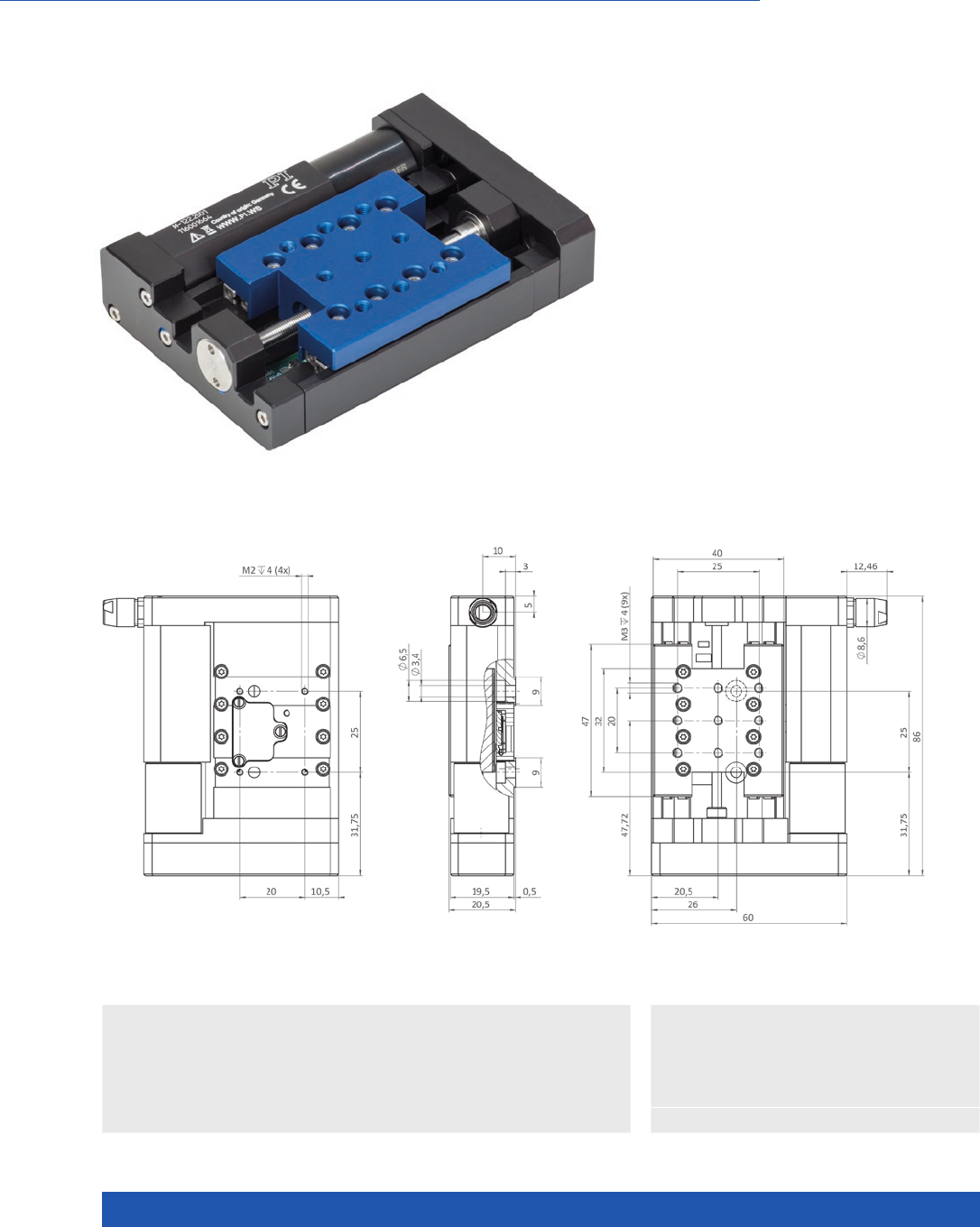
WWW.PI.WS
80
Compact Linear Stage with Direct Position Measuring
M-122.2DD1 Micro Translation Stage
>> Linear Encoder
Technology Glossary ...................... page 290
Applications
n Automation
n Laser Marking
n Optical Alignment
n Precision Micro Assembly
n Scientific Instrumentation
n Travel range 25 mm
n Integrated linear encoder option for
highest accuracy with 0.1 µm resolution
n Min. incremental motion 0.2 µm
n Max. velocity 20 mm/s
n Ball screw for high velocities and number
of cycles
M-122.2DD1, dimensions in mm
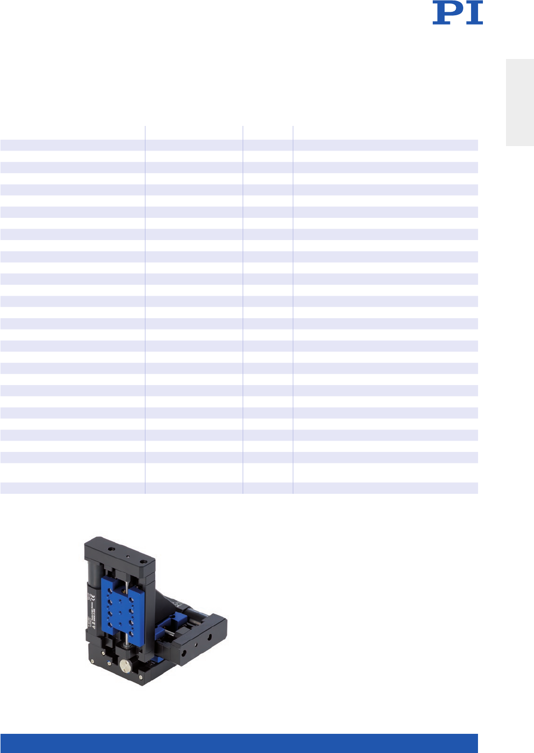
MOTION | POSITIONING
81
M-122.2DD1 Unit Tolerance
Motion and positioning
Travel range 25 mm
Integrated sensor Linear encoder
Sensor resolution 0.1 µm
Design resolution 0.1 µm typ.
Minimum incremental motion 0.2 µm typ.
Backlash 0.2 µm typ.
Unidirectional repeatability 0.15 µm typ.
Pitch ±150 µrad typ.
Yaw ±150 µrad typ.
Velocity 20 mm/s max.
Reference point switch repeatability 1 µm typ.
Mechanical properties
Drive screw Ball screw
Stiffness in motion direction 0.25 N/µm
Load capacity 50 N max.
Push/pull force 20 N max.
Lateral force 25 N max.
Drive properties
Motor type DC motor
Operating voltage 0 to ±12 V DC
Motor power 2.25 W
Drive screw pitch 0.5 mm
Reference and limit switches Hall effect
Miscellaneous
Cable length 0.5 m
Operating temperature range 10 to 50 °C
Material Aluminum, steel
Mass 0.22 kg
Recommended controllers C-863
C-884
XYZ setup consisting of three
M-122.2DD1 microtranslation stages.
Translation Stages
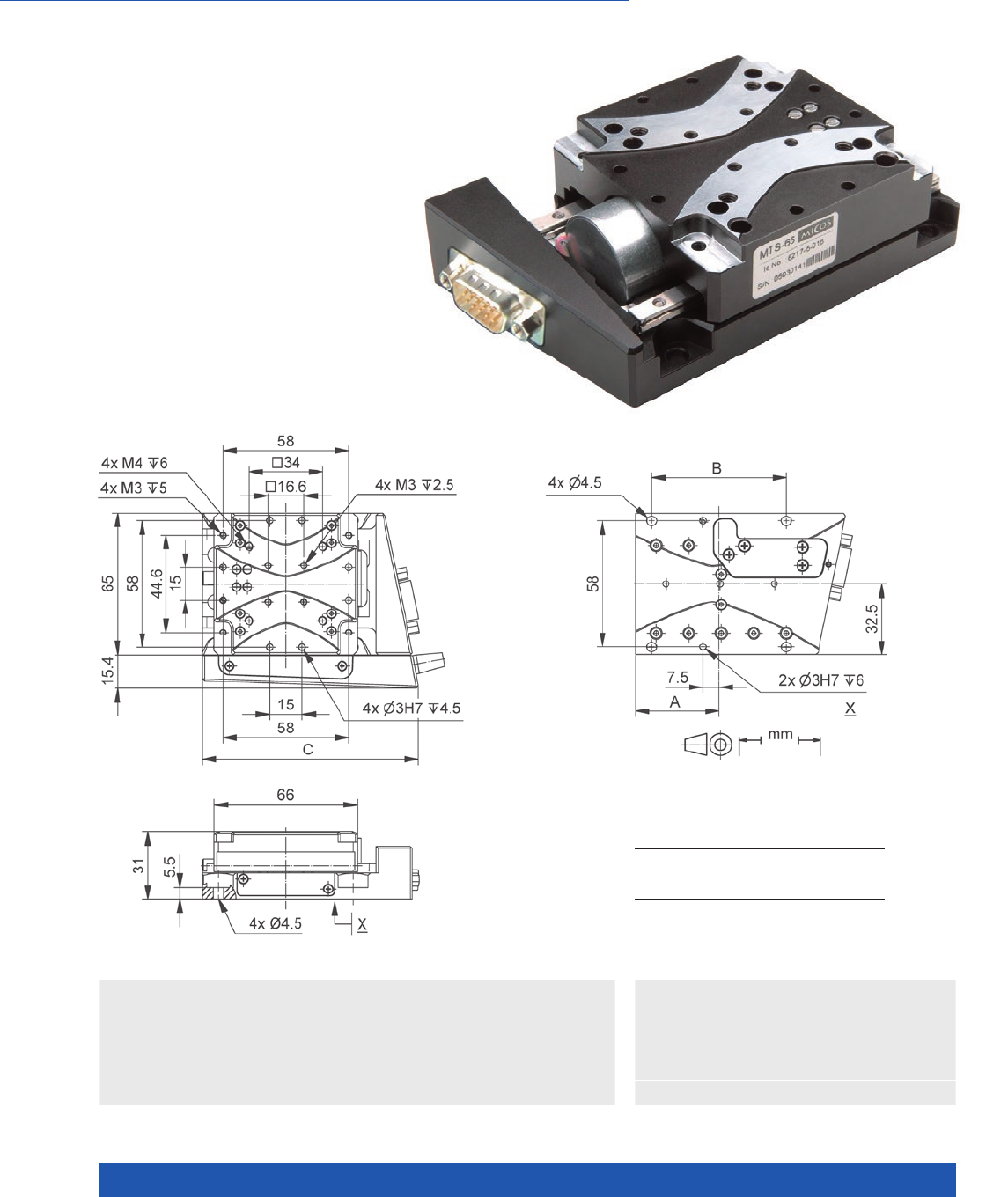
WWW.PI.WS
82
Robust Design for Industrial Use
MTS-65 Miniature Linear Stage
Technology Glossary ...................... page 290
Applications
n Autofocus
n Biotechnology
n Automation
n Laser Marking
n Scientific Instrumentation
n Travel ranges to 52 mm (2”)
n Repeatability to 0.1 µm
n Load capacity to 2 kg
Travel range/mm 13 26 52
A / mm
B / mm
C / mm
38.5
62
99.5
45
75
112.5
62
105
147.5
MTS-65, dimensions in mm
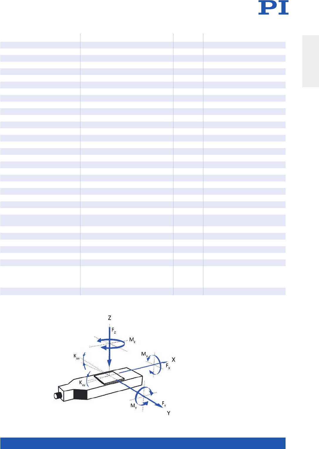
MOTION | POSITIONING
83
621792x03 Unit Tolerance
Active axes X
Motion and positioning
Travel range 13 / 26 / 52 mm
Design resolution 5 (full step) µm
Minimum incremental motion 0.1 µm typ.
Unidirectional repeatability 0.2 µm typ.
Bidirectional repeatability ±5.0 µm typ.
Straightness ±1.0 / ±2.0 / ±3.0 µm typ.
Flatness ±1.0 / ±2.0 / ±3.0 µm typ.
Pitch ±40 / ±60 / ±80 µrad typ.
Yaw ±40 µrad typ.
Max. velocity 8 mm/s max.
Mechanical properties
Drive screw type Ball screw
Drive screw pitch 1 mm
Load capacity 10 N max.
Push/pull force 3 N max.
Holding force, power off 3 N typ.
Permissible lateral force 10 N max.
Permissible torque Mx in X 0.4 N·m max.
Permissible torque My in Y 0.6 N·m max.
Permissible torque Mz in Z 0.4 N·m max.
Drive properties
Motor type 2-phase stepper motor
Operating voltage, nominal 24 V nom.
Operating voltage, max. 48 V max.
Step resolution 200 Full steps/
rev.
Limit switches Optical
Miscellaneous
Operating temperature range 5 to 40 °C
Material Aluminum, black anodized
Mass 0.4 / 0.6 / 0.8 kg ±5 %
Connector HD Sub-D 15 (m)
Recommended controllers C-663.12 (single axis)
SMC Hydra (double axis)
C-885 with C-663.12C885 (up to 20 axes)
ACS modular controller
Connecting cables for motor and sensor are not in the scope of delivery and must be ordered separately.
Ask about custom designs!
Direction of the axes
and torques for linear stages
Translation Stages
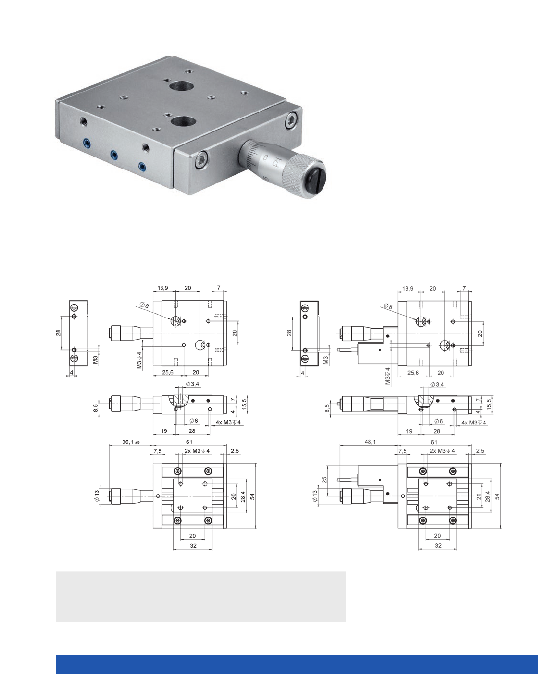
WWW.PI.WS
84
Precision Crossed Roller Guides, PiezoMike Option, XY(Z) Combinations
M-105 / M-106 Microtranslation Stage
Applications
n Manual sample manipulation
n Travel range to 18 mm
n All-stainless-steel construction
n XY and XYZ combinations
n Resolution to 0.1 µm
n Optional PiezoMike with 10 nm resolution
n Optional motor drives
The M-105 and M-106 linear stages are available
in X, XY, and XYZ configurations, and allow travel
ranges of up to 18 mm. They have crossed roller
bearings that allow a guiding accuracy of better
than 2 µm. The carriage is preloaded against the
precision micrometer screw with springs to sup-
press backlash. With the XYZ version, the Z axis
is mounted with an adapter bracket so that the
load acts in the direction of the spring preload.
M-105.10, dimensions in mm M-105.1P, dimensions in mm

MOTION | POSITIONING
85
* Versions M-105.2x, M-106.2x and M-105.3x, M-106.x0 are combinations of basic .1x. versions
** Motorized versions achieve up to 50 nm.
M-105.10* M-105.1P* M-106.10* Unit Tolerance
Travel range 18 18 5 mm
Piezo fine travel range – 30 – µm
Min. incremental
motion (piezo drive)
– 0.01 – µm
Minimum incremental
motion (micrometer
screw)**
1 1 0.1 µm
Backlash 2 2 2 µm
Straightness 2 2 2 µm
Flatness 2 2 2 µm
Load capacity 100 100 100 N max.
Push/pull force 20 / 4 20 / 4 20 / 4 N max.
Lateral force 25 25 25 N max.
Drive M-626.00 P-854.00 M-653.00
Drive screw pitch
(coarse / fine)
0.5 / – 0.5 / – 0.4 / 0.02 mm/rev.
Mass 0.32 0.38 0.33 kg
Housing material St St St
Recommended piezo
driver
– E-610, E-500 system –
Translation Stages
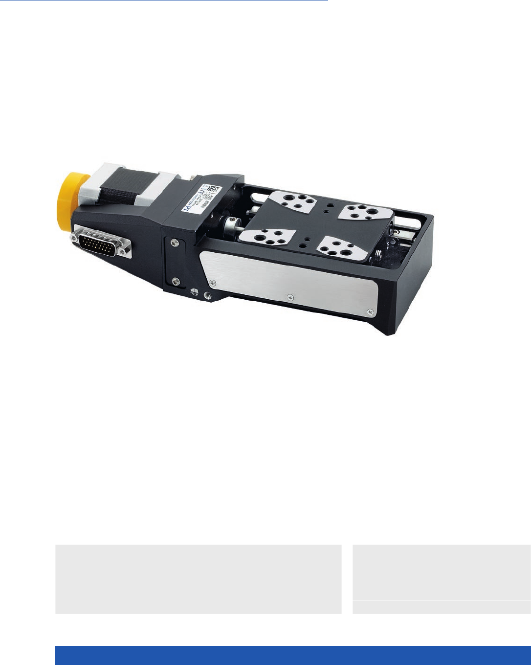
WWW.PI.WS
86
Compact Design, for Loads to 10 kg
L-509 Precision Linear Stage
>> ActiveDrive
>> Linear Encoder
>> Vacuum-Compatible Versions
Technology Glossary ...................... page 290
Applications
n Autofocus
n Biotechnology
n Automation
n Laser Cutting
n Optical Alignment
n Scientific Instrumentation
n Travel ranges from 26 to 102 mm (1” to 4”)
n Repeatability to 0.1 µm
n Optional with Direct-Measuring Linear Encoder
n ActiveDrive DC, DC, BLDC, and DC gear motors
n Stepper motors
n Direction-sensing reference point switch

MOTION | POSITIONING
87
Stages with stepper
motor and ActiveDrive
DC motor
L-509.xxADxx L-509.xxSD00 / L-509.xASD00 Unit Tolerance
Motion
Active axes X X
Travel range L-509.1xADxx: 26
L-509.2xADxx: 52
L-509.4xADxx: 102
L-509.1xSDxx: 26
L-509.2xSDxx: 52
L-509.4xSDxx: 102
mm
Pitch / yaw L-509.1xADxx: ±60
L-509.2xADxx: ±90
L-509.4xADxx: ±120
L-509.1xSDxx: ±60
L-509.2xSDxx: ±90
L-509.4xSDxx: ±120
µrad typ.
Straightness / flatness L-509.1xADxx: 2
L-509.2xADxx: 4
L-509.4xADxx: 8
L-509.1xSDxx: 2
L-509.2xSDxx: 4
L-509.4xSDxx: 8
µm typ.
Velocity 50 20 mm/s max.
L-509.xxADxx L-509.xxSD00 L-509.xASD00 Unit Tolerance
Positioning
Integrated sensor L-509.xxAD10:
Incremental rotary
encoder
L-509.xxAD00:
Incremental linear
encoder
– Incremental linear
encoder
Sensor signal A/B quadrature, TTL – Sin/cos, 1 V peak-peak,
20 µm signal period
Design resolution L-509.xxAD10: 0.061
L-509.xxAD00: 0.05
5.0 0.005 µm
Sensor resolution
rotary encoder
L-509.xxAD10: 16384 – – Cts./rev.
Sensor resolution
linear encoder
L-509.xxAD00: 0.05 – 0.005 µm
Resolution stepper
motor
– 200 200 Full
steps/
rev.
Minimum incremental
motion
L-509.xxAD10: 0.8
L-509.xxAD00: 0.2
0.1 0.02 µm typ.
Unidirectional
repeatability
L-509.xxAD10: 0.2
L-509.xxAD00: 0.1
0.3 0.1 µm typ.
Bidirectional
repeatability
L-509.xxAD10: ±0.5
L-509.14AD00: ±0.3
L-509.24AD00: ±0.2
L-509.44AD00: ±0.2
±1 ±0.2 µm typ.
Reference and limit
switches
Optical Optical Optical
L-509.xxADxx / L-509.xxSD00 / L-509.xASD00 Unit Tolerance
Mechanical properties
Drive screw type Crossed roller guide with anti-creep system
Drive screw pitch 1 mm
Guide type Recirculating ball bearings
Holding force, power off L-509.xxADxx: 20
L-509.xxSD00 / L-509.xASD00: 60
N typ.
Push/pull force Fx,
power on
60 N max.
Permissible lateral force 50 N max.
Load capacity 100 N max.
Permissible torque Mx
in θX
30 N·m max.
Permissible torque My
in θY
25 N·m max.
Permissible torque Mz
in θZ
20 N·m max.
Translation Stages

WWW.PI.WS
88
Stages with stepper
motor and ActiveDrive
DC motor
L-509.xxADxx L-509.xxSD00 / L-509.xASD00 Unit Tolerance
Drive properties
Motor type ActiveDrive DC motor (PWM) Stepper motor, 2-phase
Operating voltage,
nominal
24 24 V nom.
Operating voltage, max. 24 48 V max.
L-509.xxADxx L-509.xxSD00 L-509.xASD00 Unit Tolerance
Miscellaneous
Operating temperature
range
5 to 40 5 to 40 5 to 40 °C
Material Aluminum, steel Aluminum, steel Aluminum, steel
Mass L-509.10AD10: 1.4
L-509.20AD10: 1.5
L-509.40AD10: 1.7
L-509.14AD00: 1.4
L-509.24AD00: 1.6
L-509.44AD00: 1.8
L-509.10SD00: 1.4
L-509.20SD00: 1.5
L-509.40SD00: 1.7
L-509.1ASD00: 1.5
L-509.2ASD00: 1.6
L-509.4ASD00: 1.8
kg ±5 %
Moved mass, unloaded L-509.x0AD10: 0.22
L-509.14AD00: 0.24
L-509.24AD00: 0.24
L-509.44AD00: 0.25
0.22 L-509.1ASD00: 0.24
L-509.2ASD00: 0.24
L-509.4ASD00: 0.25
kg ±5 %
Connection 1 × Sub-D 15 (m)
(motor/sensor)
1 × HD Sub-D 26 (m)
(motor)
1 × HD Sub-D 26 (m)
(motor)
1 × Sub-D 9 (m) (sensor)
Recommended
controllers / drivers
C-863 (single axis)
C-884 (up to 6 axes)
C-885 with
C-863.20C885
(to 40 axes)
ACS modular controller
C-663.12 (single axis)
SMC Hydra
(double axis)
C-885 with
C-663.12C885
(up to 20 axes)
ACS modular controller
C-663.12 (single axis)
SMC Hydra
(double axis)
C-885 with
C-663.12C885
(up to 20 axes)
ACS modular controller
Stages with DC motor
and BLDC motor
L-509.xxDG10 L-509.xx3111 /
L-509.xx3132
L-509.xx5132 Unit Tolerance
Motion
Active axes X X X
Travel range L-509.10DG10: 26
L-509.20DG10: 52
L-509.40DG10: 102
L-509.023xxx: 26
L-509.033xxx: 52
L-509.053xxx: 102
L-509.025132: 26
L-509.035132: 52
L-509.055132: 102
mm
Pitch / yaw L-509.10DG10: ±60
L-509.20DG10: ±90
L-509.40DG10: ±120
L-509.023xxx: ±60
L-509.033xxx: ±90
L-509.053xxx: ±120
L-509.025132: ±60
L-509.035132: ±90
L-509.055132: ±120
µrad typ.
Straightness / flatness L-509.10DG10: 2
L-509.20DG10: 4
L-509.40DG10: 8
L-509.023xxx: 2
L-509.033xxx: 4
L-509.053xxx: 8
L-509.025132: 2
L-509.035132: 4
L-509.055132: 8
µm typ.
Velocity 3 50 50 mm/s max.

MOTION | POSITIONING
89
L-509.xxDG10 L-509.xx3111 L-509.xxx132 Unit Tolerance
Positioning
Integrated sensor Incremental rotary
encoder
Incremental linear
encoder
Incremental rotary
encoder
Sensor signal A/B quadrature, TTL Sin/cos, 1 V peak-peak,
20 µm signal period
A/B quadrature, TTL
Design resolution 0.008 0.005 0.05 µm
Sensor resolution
rotary encoder
4096 – 20000 Cts./rev.
Sensor resolution
linear encoder
– – µm
Minimum incremental
motion
0.1 0.1 0.5 µm typ.
Unidirectional
repeatability
0.1 0.1 0.2 µm typ.
Bidirectional repeatability ±2 ±0.2 ±0.5 µm typ.
Reference and limit
switches
Optical Optical Optical
L-509.xxDG10 L-509.xx3xxx
L-509.xx5xxx
Unit Tolerance
Mechanical properties
Drive screw type Crossed roller guide with anti-creep
system
Crossed roller guide with anti-creep
system
Drive screw pitch 1 1 mm
Gear ratio 2401:81 –
Guide type Recirculating ball bearings Recirculating ball bearings
Holding force, power off L-509.10DG10: 40
L-509.20DG10: 60
L-509.40DG10: 60
20 N typ.
Push/pull force Fx,
power on
60 60 N max.
Permissible lateral force 50 50 N max.
Load capacity 100 100 N max.
Permissible torque Mx
in θX
30 30 N·m max.
Permissible torque My
in θY
25 25 N·m max.
Permissible torque Mz
in θZ
20 20 N·m max.
L-509.xxDG10 L-509.xx3xxx L-509.xx5xxx Unit Tolerance
Drive properties
Motor type DC motor
(with gearhead)
DC motor Brushless DC motor,
3-phase
Operating voltage,
nominal
24 24 24 V nom.
Operating voltage, max. 48 48 48 V max.
Translation Stages
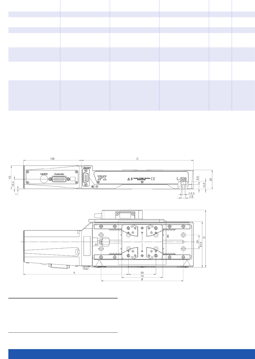
WWW.PI.WS
90
Stages with DC motor
and BLDC motor
L-509.xxDG10 L-509.xx3xxx L-509.xx5132 Unit Tolerance
Miscellaneous
Operating temperature
range
5 to 40 5 to 40 5 to 40 °C
Material Aluminum, steel Aluminum, steel Aluminum, steel
Mass L-509.10DG10: 1.4
L-509.20DG10: 1.6
L-509.40DG10: 1.9
L-509.023xxx: 1.2
L-509.033xxx: 1.3
L-509.053xxx: 1.5
L-509.025132: 1.4
L-509.035132: 1.5
L-509.055132: 1.7
kg ±5 %
Moved mass, unloaded 0.22 L-509.023111: 0.24
L-509.033111: 0.24
L-509.053111: 0.25
0.22 kg ±5 %
Connection 1 × HD Sub-D 26 (m)
(motor/sensor)
1 × HD Sub-D 26 (m)
(motor)
L-509.xx3111 additional:
1 × Sub-D 9 (m) (sensor)
1 × HD Sub-D 26 (m)
(motor/sensor)
Recommended
controllers / drivers
C-863 (single axis)
C-884 (up to 6 axes)
C-885 with
C-863.20C885
(to 40 axes)
ACS modular controller
C-863 (single axis)
C-884 (up to 6 axes)
C-885 with
C-863.20C885
(to 40 axes)
ACS modular controller
C-891 (single axis)
C-885 with
C-891.10C885
(up to 20 axes)
ACS modular controller
All cables required for operation with the ordered controller are included in the scope of delivery.
The cable length is 3 m. Cable for connecting to other controllers can be ordered as accessory.
Ask about custom designs!
L-509 versions with DC and BLDC motor, dimensions in mm
A B C D
L-509.023111
L-509.023132
L-509.025132
L-509.03 3111
L-509.033132
L-509.035132
L-509.053111
L-509.053132
L-509.055132
157.3
157.3
157.3
166.8
166.8
166.8
191.8
191.8
191.8
100
100
100
100
100
100
150
150
150
135.3
135.3
135.3
154.3
154.3
154.3
204.3
204.3
204.3
104.4
–
–
104.4
–
–
104.4
–
–
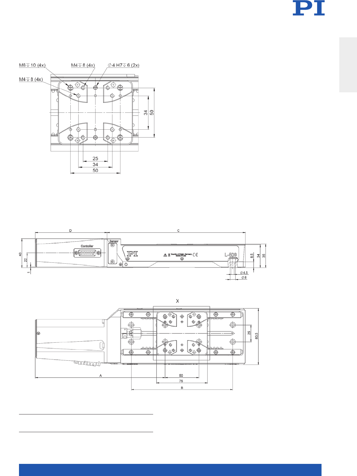
MOTION | POSITIONING
91
Detail drawing of the L-509 motion platform
Translation Stages
A B C D
L-509.10DG10
L-509.20DG10
L-509.40DG10
157.3
166.8
191.8
100
100
150
135.3
154.3
204.3
106
106
106
L-509 versions with DC gear motor, dimensions in mm
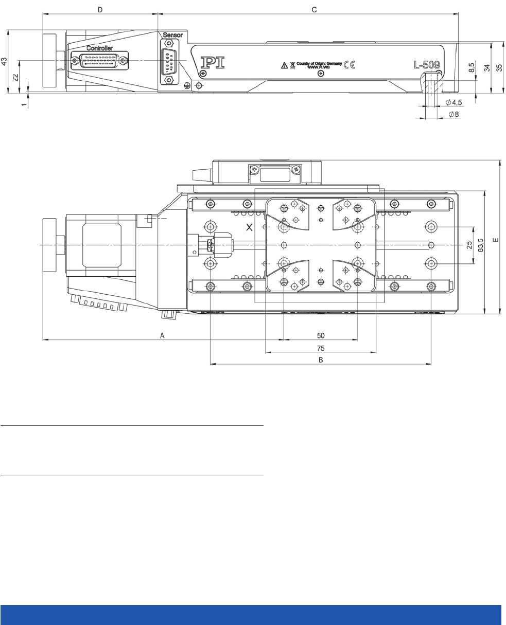
WWW.PI.WS
92
L-509 versions with stepper motor, dimensions in mm
A B C D E
L-509.10SD 0 0
L-509.1ASD 0 0
L-509.20SD00
L-509.2ASD00
L-509.40SD0 0
L-509.4ASD00
129.3
129.3
138.8
138.8
163.8
163.8
100
100
100
100
150
150
135.3
135.3
154.3
154.3
204.3
204.3
78
78
78
78
78
78
–
104.2
–
104.2
–
104.2
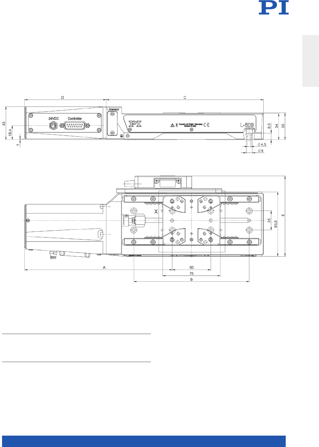
MOTION | POSITIONING
93
Translation Stages
L-509 versions with ActiveDrive DC motor, dimensions in mm
A B C D E
L-509.10AD10
L-509.14AD00
L-509.20AD10
L-509.24AD00
L-509.40AD10
L-509.44AD00
157.3
157.3
166.8
166.8
191.8
191.8
100
100
100
100
150
150
135.3
135.3
154.3
154.3
204.3
204.3
106
106
106
106
106
106
–
104.2
–
104.2
–
104.2
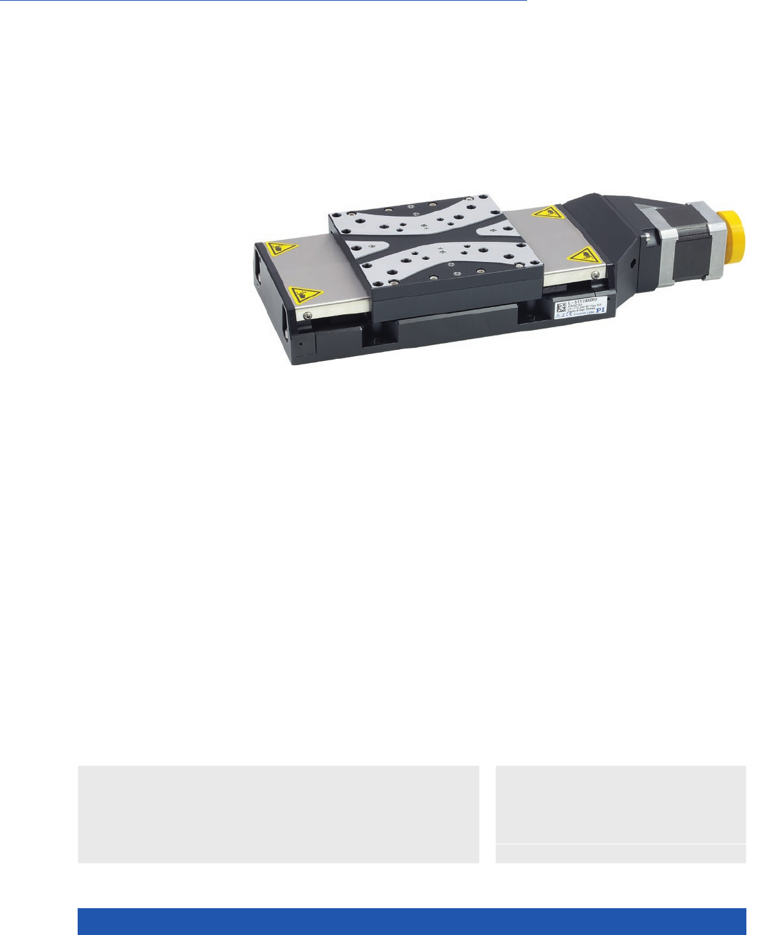
WWW.PI.WS
94
High Travel Accuracy
L-511 High-Precision Linear Stage
>> ActiveDrive
>> Linear Encoder
>> Vacuum-Compatible Versions
Technology Glossary ...................... page 290
Applications
n Autofocus
n Biotechnology
n Automation
n Laser Cutting
n Optical Alignment
n Scientific Instrumentation
Drive types
n .xxAD variant: ActiveDrive DC motor for high
velocity: Control via pulse-width-modulated
(PWM) signals, the operating voltage is
attained via an amplifier integrated in the
motor housing.
n .xxDG variant: DC servo motor with gearhead
for high torques and resolution at low motor
power
n .xxSD variant: 2-phase stepper motor for
low velocity and high resolution
n .xx3xxx variant: DC motor
n .xx5xxx variant: Brushless DC motor
Position measurement
n Integrated rotary encoder on the motor
shaft (xxAD10, xxDG10, xxxx32).
n Incremental linear encoder
(xxAD00, xASD00, xxxx11).
Reference-class linear stage
Recirculating ball bearings for high travel accuracy and load capacity. Precision
ball screw with 2 mm pitch. Stress-relieved aluminum base for highest sta-
bility. Noncontact limit switches. Noncontact optical reference point switch with
direction sensing in the middle of the travel range.
Highly accurate position measuring with incremental linear encoder
Noncontact optical linear encoders measure the actual position directly at the
motion platform with the greatest accuracy so that nonlinearity, mechanical
play or elastic deformation have no influence on position measuring.
Minimum incremental motion and slow motion
In conjunction with the SMC Hydra controller, versions with stepper motor and
integrated linear encoder (L-511.xASD00) achieve repeatable minimum incre-
mental motion in the range of the sensor resolution. The same configuration
achieves constant low velocities of a few sensor increments per second.
n Travel ranges to 155 mm (6”)
n Repeatability to 0.1 µm
n ActiveDrive DC, DC, BLDC, and DC gear motors
n Stepper motors
n Optional linear encoder for direct position measurement
n Direction-sensing reference point switch

MOTION | POSITIONING
95
Stages with stepper
motor and ActiveDrive
DC motor
L-511.xxADxx L-511.xxSD00 / L-511.xASD00 Unit Tolerance
Motion
Active axes X X
Travel range L-511.2xADxx: 52
L-511.4xADxx: 102
L-511.6xADxx: 155
L-511.2xSD00: 52
L-511.4xSD00: 102
L-511.6xSD00: 155
mm
Pitch / yaw L-511.2xADxx: ±40
L-511.4xADxx: ±60
L-511.6xADxx: ±70
L-511.2xSD00: ±40
L-511.4xSD00: ±60
L-511.6xSD00: ±70
µrad typ.
Straightness / flatness L-511.2xADxx: ±1.5
L-511.4xADxx: ±2.5
L-511.6xADxx: ±3.0
L-511.2xSD00: ±1.5
L-511.4xSD00: ±2.5
L-511.6xSD00: ±3.0
µm typ.
Velocity 90 45 mm/s max.
L-511.xxADxx L-511.xxSD00 L-511.xASD00 Unit Tolerance
Positioning
Integrated sensor L-511.xxAD10:
Incremental rotary
encoder
L-511xxAD00:
Incremental linear
encoder
– Incremental linear
encoder
Sensor signal A/B quadrature, TTL – Sin/cos, 1 V peak-peak,
20 µm signal period
Design resolution L-511.xxAD10: 0.122
L-511.xxAD00: 0.05
10.0 0.005 µm
Sensor resolution
rotary encoder
L-511.xxAD10: 16384 – – Cts./rev.
Sensor resolution
linear encoder
L-511.xxAD00: 0.05 – 0.005 µm
Resolution stepper
motor
– 200 200 Full steps/
rev.
Minimum incremental
motion
L-511.xxAD10: 0.488
L-511.xxAD00: 0.1
0.2 0.02 µm typ.
Unidirectional
repeatability
L-511.xxAD10: 0.488
L-511.xxAD00: 0.1
0.2 0.1 µm typ.
Bidirectional
repeatability
L-511.xxAD10: ±1.250
L-511.xxAD00: ±0.2
±2 ±0.2 µm typ.
Reference and limit
switches
Optical Optical Optical
L-511.xxADxx / L-511.xxSD00 / L-511.xASD00 Unit Tolerance
Mechanical properties
Drive screw type Ball screw
Drive screw pitch 2 mm
Guide type Recirculating ball bearings
Holding force, power off L-511.xxADxx: 20
L-511.xxSD00 / L-511.xASD00: 60
N typ.
Push/pull force Fx,
power on
100 N max.
Permissible lateral force 250 N max.
Load capacity 500 N max.
Permissible torque Mx
in θX
60 N·m max.
Permissible torque My
in θY
30 N·m max.
Permissible torque Mz
in θZ
30 N·m max.
Translation Stages

WWW.PI.WS
96
Stages with stepper
motor and ActiveDrive
DC motor
L-511.xxADxx L-511.xxSD00 / L-511.xASD00 Unit Tolerance
Drive properties
Motor type ActiveDrive DC motor (PWM) Stepper motor, 2-phase
Operating voltage,
nominal
24 24 V nom.
Operating voltage, max. 24 48 V max.
L-511.xxADxx L-511.xxSD00 L-511.xASD00 Unit Tolerance
Miscellaneous
Operating temperature
range
5 to 40 5 to 40 5 to 40 °C
Material Aluminum,
stainless steel
Aluminum,
stainless steel
Aluminum,
stainless steel
Mass L-511.2xADxx: .2.5
L-511.40AD10: 2.8
L-511.60AD10: 3.3
L-511.44AD00: 2.7
L-511.64AD00: 3.5
L-511.20SDxx: 2.4
L-511.40SDxx: 2.6
L-511.60SDxx: 3.1
L-511.2ASDxx: 2.4
L-511.4ASDxx: 2.6
L-511.6ASDxx: 3.1
kg ±5 %
Moved mass, unloaded L-511.2xADxx: 0.6
L-511.4xADxx: 0.6
L-511.6xADxx: 0.65
L-511.20SDxx: 0.6
L-511.40SDxx: 0.6
L-511.60SDxx: 0.65
L-511.2ASDxx: 0.6
L-511.4ASDxx: 0.6
L-511.6ASDxx: 0.65
kg ±5 %
Connection 1 × Sub-D 15 (m)
(motor/sensor)
1 × HD Sub-D 26 (m)
(motor)
1 × HD Sub-D 26 (m)
(motor)
1 × Sub-D 9 (m) (sensor)
Recommended
controllers / drivers
C-863 (single axis)
C-884 (up to 6 axes)
C-885 with
C-863.20C885
(to 40 axes)
ACS modular controller
C-663.12 (single axis)
SMC Hydra
(double axis)
C-885 with
C-663.12C885
(up to 20 axes)
ACS modular controller
C-663.12 (single axis)
SMC Hydra
(double axis)
C-885 with
C-663.12C885
(up to 20 axes)
ACS modular controller
Stages with DC motor
and BLDC motor
L-511.xxDG10 L-511.xx3111 / L-511.xx3132
L-511.xx5111 / L-511.xx5132
Unit Tolerance
Motion
Active axes X X
Travel range L-511.20DG10: 52
L-511.40DG10: 102
L-511.60DG10: 155
L-511.03xxxx: 52
L-511.05xxxx: 102
L-511.07xxxx: 155
mm
Pitch / yaw L-511.20DG10: ±40
L-511.40DG10: ±60
L-511.60DG10: ±70
L-511.03xxxx: ±40
L-511.05xxxx: ±60
L-511.07xxxx: ±70
µrad typ.
Straightness / flatness L-511.20DG10: ±1.5
L-511.40DG10: ±2.5
L-511.60DG10: ±3.0
L-511.03xxxx: ±1.5
L-511.05xxxx: ±2.5
L-511.07xxxx: ±3.0
µm typ.
Velocity 6 90 mm/s max.

MOTION | POSITIONING
97
L-511.xxDG10 L-511.xx3111 /
L-511.xx5111
L-511.xx3132 /
L-511.xx5132
Unit Tolerance
Positioning
Integrated sensor Incremental rotary
encoder
L-511.xx3111:
Incremental linear
encoder
L-511.xx5111:
Incremental rotary
encoder, incremental
rotary encoder
Incremental rotary
encoder
Sensor signal A/B quadrature, TTL Linear encoder:
Sin/cos, 1 V peak-peak,
20 µm signal period
Rotary encoder:
A/B quadrature, TTL
A/B quadrature, TTL
Design resolution 0.017 L-511.xx3111: 0.005
L-511.xx5111: 0.05
0.1 µm
Sensor resolution
rotary encoder
4096 20000 20000 Cts./rev.
Sensor resolution
linear encoder
– L-511.xx3111: 0.005
L-511.xx5111: 0.05
0.1 µm
Minimum
incremental motion
0.1 0.1 0.2 µm typ.
Unidirectional
repeatability
0.2 0.1 0.2 µm typ.
Bidirectional
repeatability
±2 ±0.1 ±1.25 µm typ.
Reference and limit
switches
Optical Optical Optical
L-511.xxDG10 L-511.xx3xxx /
L-511.xx5xxx
Unit Tolerance
Mechanical properties
Drive screw type Ball screw Ball screw
Drive screw pitch 2 2 mm
Gear ratio 2401:81 –
Guide type Recirculating ball bearings Recirculating ball bearings
Holding force,
power off
100 20 N typ.
Push/pull force Fx,
power on
100 100 N max.
Permissible lateral force 250 250 N max.
Load capacity 500 500 N max.
Permissible torque Mx
in θX
60 60 N·m max.
Permissible torque My
in θY
30 30 N·m max.
Permissible torque Mz
in θZ
30 30 N·m max.
Translation Stages

WWW.PI.WS
98
Stages with DC motor
and BLDC motor
L-511.xxDG10 L-511.xx3xxx L-511.xx5xxx Unit Tolerance
Drive properties
Motor type DC motor
(with gearhead)
DC motor Brushless DC motor,
3-phase
Operating voltage,
nominal
24 24 24 V nom.
Operating voltage, max. 48 48 48 V max.
Miscellaneous
Operating temperature
range
5 to 40 5 to 40 5 to 40 °C
Mass L-511.20DG10: 2.5
L-511.40DG10: 2.7
L-511.60DG10: 2.9
L-511.033xxx: 2.5
L-511.053xxx: 2.6
L-511.073xxx: 3.1
L-511.035xxx: 2.4
L-511.055xxx: 2.7
L-511.075xxx: 3.0
kg ±5 %
Moved mass, unloaded L-511.20DG10: 0.6
L-511.40DG10: 0.6
L-511.60DG10: 0.65
L-511.033xxx: 0.6
L-511.053xxx: 0.6
L-511.073xxx: 0.65
L-511.035xxx: 0.6
L-511.055xxx: 0.6
L-511.075xxx: 0.65
kg ±5 %
Connection 1 × HD Sub-D 26 (m)
(motor/sensor)
L-511.xx3111:
1 × HD Sub-D 26 (m)
(motor),
1 × Sub-D 9 (m) (sensor)
L-511.xx3132:
1 × HD Sub-D 26 (m)
(motor/sensor)
L-511.xx5111:
1 × HD Sub-D 26 (m)
(motor/sensor),
1 × Sub-D 9 (m) (sensor)
L-511.xx5132:
1 × HD Sub-D 26 (m)
(motor/sensor)
Recommended
controllers / drivers
C-863 (single axis)
C-884 (up to 6 axes)
C-885 with
C-863.20C885
(to 40 axes)
ACS modular controller
C-863 (single axis)
C-884 (up to 6 axes)
C-885 with
C-863.20C885
(to 40 axes)
ACS modular controller
L-511.xx5111:
C-891 (single axis)
C-885 with
C-891.10C885
(up to 20 axes)
ACS modular controller
L-511.xx5132 additional:
SMC Hydra
(double axis)
All cables required for operation with the ordered controller are included in the scope of delivery.
The cable length is 3 m. Cable for connecting to other controllers can be ordered as accessory.
Ask about custom designs!
The L-511 reliably performs repeatable 20-nm steps with the linear encoder
and SMC Hydra motion controller
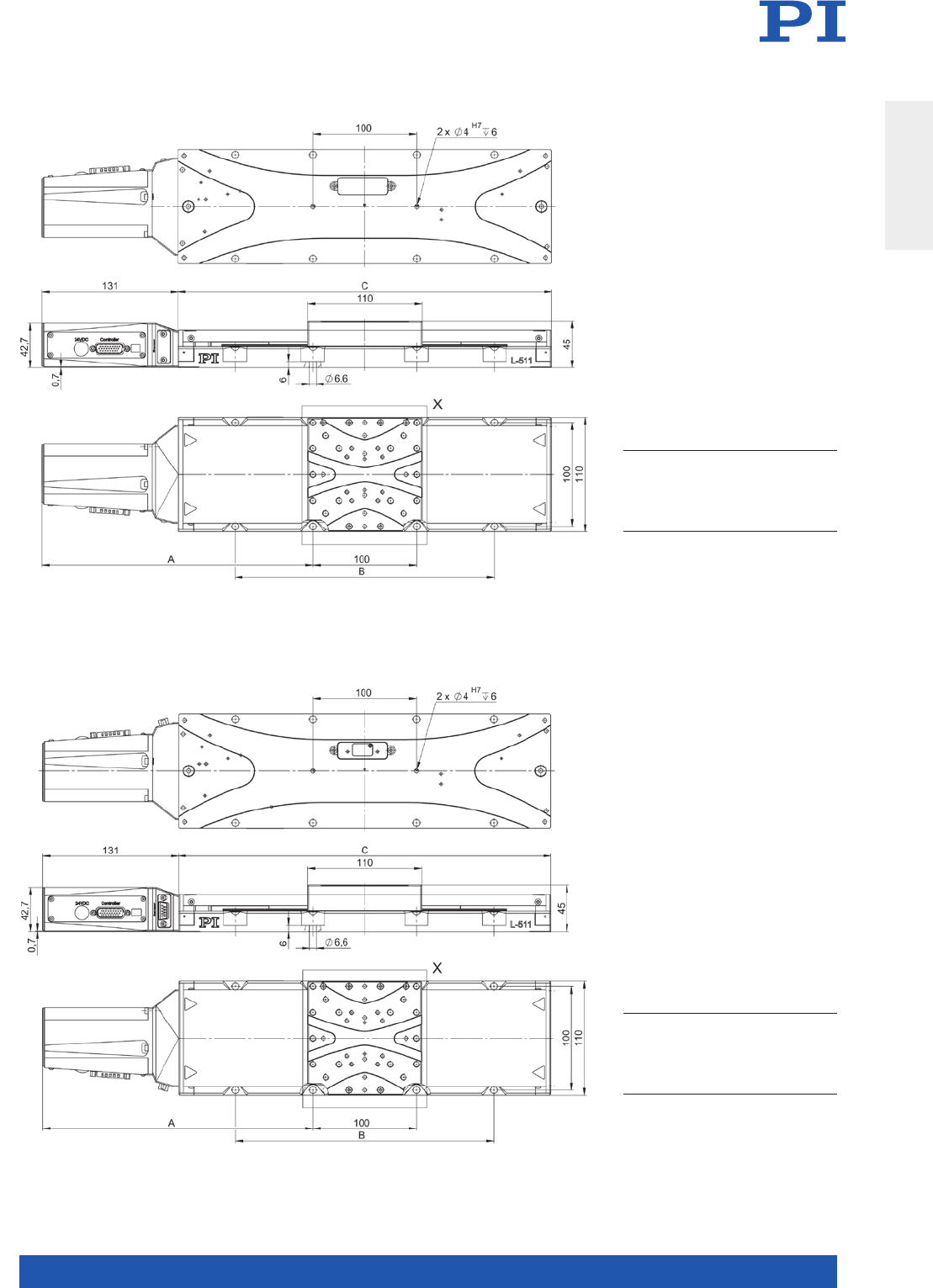
MOTION | POSITIONING
99
L-511 versions with DC and BLDC motor, and rotary encoder, dimensions in mm
A B C
L-511.033132
L-511.035132
L-511.053132
L-511.055132
L-511.073132
L-511.075132
186
186
211
211
261
261
–
–
–
–
250
250
210
210
260
260
360
360
L-511 versions with DC and BLDC motor, and linear encoder, dimensions in mm
A B C
L-511.033111
L-511.053111
L-511.073111
L-511.035111
L-511.055111
L-511.075111
186
211
261
186
211
261
–
–
250
–
–
250
210
260
360
210
260
360
Translation Stages
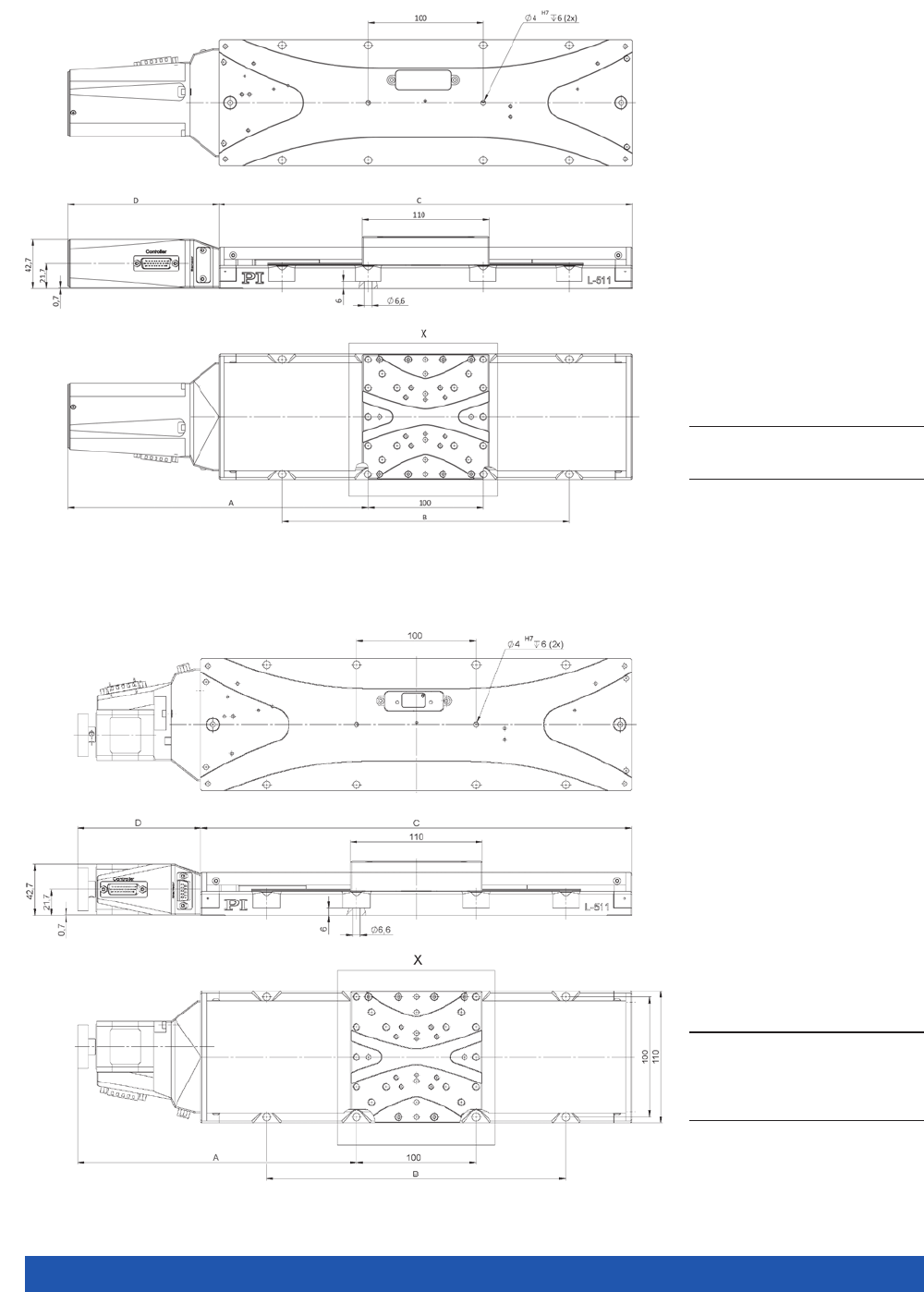
WWW.PI.WS
100
A B C D
L-511.20SD00
L-511.2ASD00
L-511. 4 0SD 0 0
L-511 4ASD00
L-511.6OSD00
L-511.6ASD00
158
158
183
183
233
233
–
–
–
–
250
250
210
210
260
260
360
360
103
103
103
103
103
103
L-511 versions with stepper motor, dimensions in mm
A B C D
L-511. 20DG10
L-511.40DG10
L-511.60DG10
186
211
261
–
–
250
210
260
360
131
131
131
L-511 versions with DC gear motor, dimensions in mm
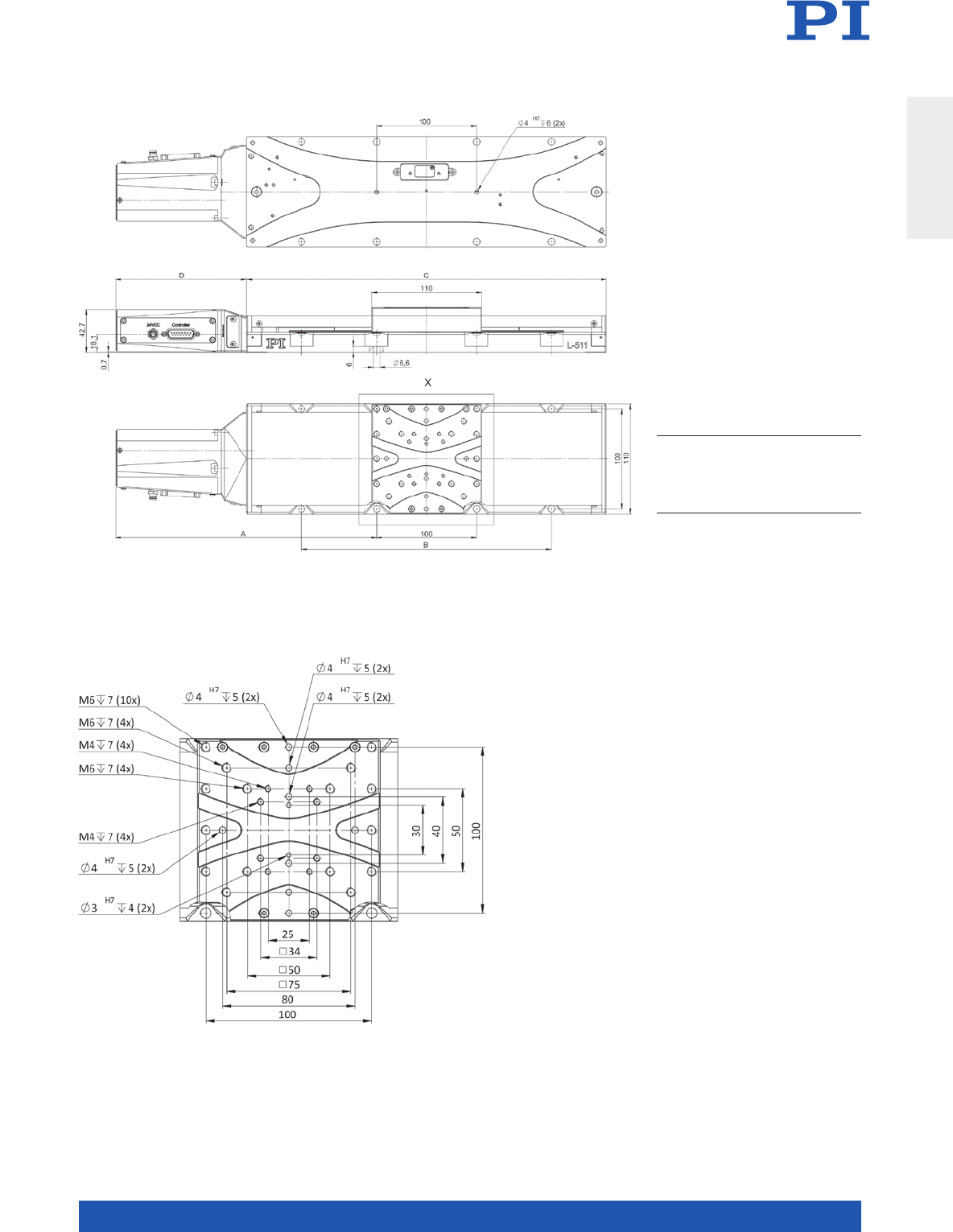
MOTION | POSITIONING
101
A B C D
L-511. 20A D10
L-511.24AD00
L-511. 4 0AD10
L-511. 4 4 AD00
L-511.60A D10
L-511.64AD00
186
186
211
211
261
261
–
–
–
–
250
250
210
210
260
260
360
360
131
131
131
131
131
131
L-511 versions with ActiveDrive DC motor, dimensions in mm
Detail drawing of the L-511 motion platform, dimensions in mm
Translation Stages
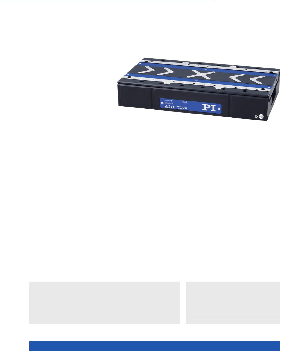
WWW.PI.WS
102
High Velocity and Precision due to Magnetic Direct Drive
V-551 PIMag® Precision Linear Stage
>> Absolute Encoder
>> Linear Encoder
>> PIMag® Magnetic Linear Motors
Technology Glossary ...................... page 290
Applications
n Biotechnology
n Electronics Manufacturing
n Medical Industry
n Metrology / Testing
n Photonics
n Scanning
n Semiconductor
n Travel ranges to 230 mm
n Velocity up to 0.5 m/s
n Absolute encoder with 1 nm resolution
n Highest precision with PIOne linear encoder:
Minimum incremental motion 0.5 nm
n High guiding accuracy
n Compact design with 160 mm width
n Crossed roller guide, anti-creep
Reference-class linear stage
Thanks to the smooth-running precision linear guides with crossed roller bear-
ings, the linear stage is particularly suitable for scanning applications with con-
stant velocity. The anti-creep system reliably prevents cage creep. The guides
have high load capacity and high precision under all operating conditions.
Direct position measurement
Position measuring takes place directly at the motion platform with the highest
accuracy so that nonlinearity, mechanical play or elastic deformation have no
influence on position measuring. The high-resolution PIOne encoder was de-
veloped by PI and, with corresponding processing of the measured values,
allows a position resolution of much less than one nanometer. The optical
and noncontact PIOne encoders are based on an interferometric measuring
principle. Due to the short signal period and the high quality of the signals,
the linearity error of PIOne encoders is less than 1 %. PIOne encoders support
direction sensing when evaluating a reference signal. Absolute encoders
supply explicit position information that enables immediate determination
of the position. This means that referencing is not required during switch-on,
which increases efficiency and safety during operation.
PIMag® magnetic direct drive
3-phase magnetic direct drives do not use mecha-
nical components in the drivetrain, they transmit
the drive force to the motion platform directly
and without friction. The drives reach high velo-
cities and accelerations. Ironless motors are par-
ticularly suitable for positioning tasks with the
highest demands on precision because there is
no undesirable interaction with the permanent
magnets. This allows smooth running even at the
lowest velocities and at the same time, there
is no vibration at high velocities. Nonlinearity in
control behavior is avoid-ed and any position can
be controlled easily. The drive force can be set
freely.

MOTION | POSITIONING
103
V-551.2x V-551.4x V-551.7x Unit Tolerance
Motion and positioning
Active axes X X X
Travel range 60 130 230 mm
Pitch ±50 ±100 ±100 µrad typ.
Yaw ±50 ±50 ±50 µrad typ.
Straightness ±1 ±1 ±2 µm typ.
Flatness ±2 ±2 ±2 µm typ.
Velocity 0.5 0.5 0.5 m/s max.
Mechanical properties
Load capacity in Z 150 150 150 N max.
Load capacity in Y 50 50 50 N max.
Moved mass 2.2 2.7 4.9 kg
Overall mass 4.2 5.5 9.7 kg
Linear guide Crossed roller bearing
with anti-creep system
Crossed roller bearing
with anti-creep system
Crossed roller bearing
with anti-creep system
V-551 Unit Tolerance
Drive properties
Drive type PIMag® linear motor, ironless, 3-phase
Intermediate
circuit voltage
110 * V DC max.
Peak force 180 N typ.
Nominal force 27 N typ.
Peak current, effective 10 A typ.
Nominal current, effective 1.5 A typ.
Force constant, effective 18 N/A typ.
Resistance per phase 3.15 Ω typ.
Inductance per phase 0.9 mH typ.
Back EMF phase-phase 16 V·s/m max.
V-551.xB V-551.xD
Encoder options
Integrated Sensor Absolute encoder PIOne incremental linear encoder
Sensor signal BiSS-C Sin/cos, 1 V peak-peak, 2 µm signal period
Sensor resolution 1 nm 0.2 nm**
Min. incremental motion 2 nm 0.5 nm
Unidirectional
repeatability
0.02 µm 0.02 µm
Bidirectional repeatability ±0.05 µm ±0.05 µm
Travel range limit Limits are set via software;
additional mechanical stop buffers.
Hall effect limit switches
Reference point switch – Encoder index
Reference point switch
repeatability
– <1 µm
V-551
Miscellaneous
Operating temperature
range
10 °C to 50 °C
Humidity 20 – 90 % rel., not condensing
Material Aluminum, black anodized
Motor connector HD Sub-D 26 (m)
Sensor connection Sub-D 15 (f)
Recommended
controllers
C-891 (single axis)
C-885 with C-891.10C885 (up to 20 axes)
ACS modular controller
* 24 V DC with C-891.120200
** interpolated
Ask about custom designs.
Translation Stages
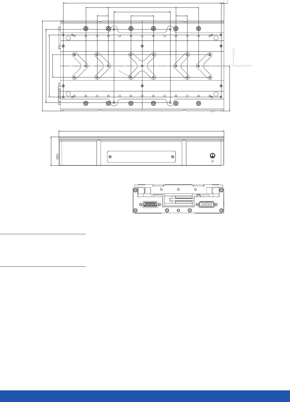
WWW.PI.WS
104
V-551, dimensions in mm
V-551.2x V-551.4x V-551.7x
Stroke
A
B
C
D
E
F
60
220
210
60
1
–
1
130
290
280
120
1
40
1
230
450
440
120
3
40
3
50,5
A
160
C
D x 40
20
40
130
110
E
B
5
F x 100
20
D x 40
M4
79,85
V-551.4x :
X
Y
V-551.2x V-551.4x V-551.7x
Stroke
60 130 230
A
220 290 450
B
210 280 440
C
60 120 120
D
113
E
-
40 40
F
113
50,5
A
160
C
D x 40
20
40
130
110
E
B
5
F x 100
20
D x 40
M4
79,85
V-551.4x :
X
Y
V-551.2x V-551.4x V-551.7x
Stroke
60 130 230
A
220 290 450
B
210 280 440
C
60 120 120
D
113
E
-
40 40
F
113
50,5
A
160
C
D x 40
20
40
130
110
E
B
5
F x 100
20
D x 40
M4
79,85
V-551.4x :
X
Y
V-551.2x V-551.4x V-551.7x
Stroke
60 130 230
A
220 290 450
B
210 280 440
C
60 120 120
D
113
E
-
40 40
F
113
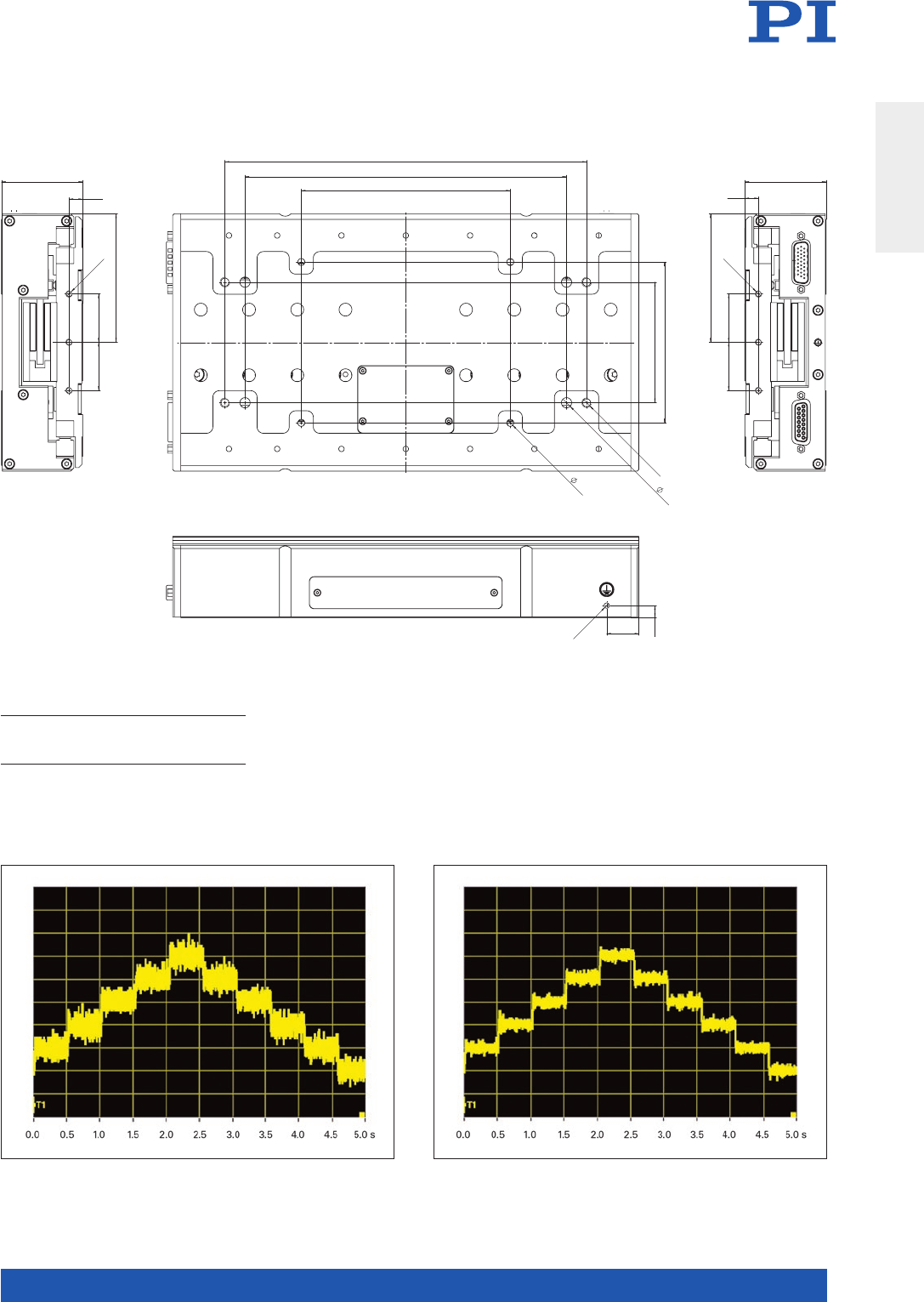
MOTION | POSITIONING
105
7,5
20
M4
I
H
G
75
100
6,4
4,4
M6
79,85
30 30
50,5
8,5
M4
79,85
30 30
50,5
8,5
M4
V-551.2x V-551.4x V-551.7x
G
125 225 225
H
175 200 250
I 130 130 190
V-551.2x V-551.4x V-551.7x
G
H
I
125
175
130
225
200
130
225
250
190
A V-551.4D with PIOne linear encoder performs a sequence of 0.5-nm steps. A V-551.4D with PIOne linear encoder performs a sequence of 1-nm steps.
Translation Stages
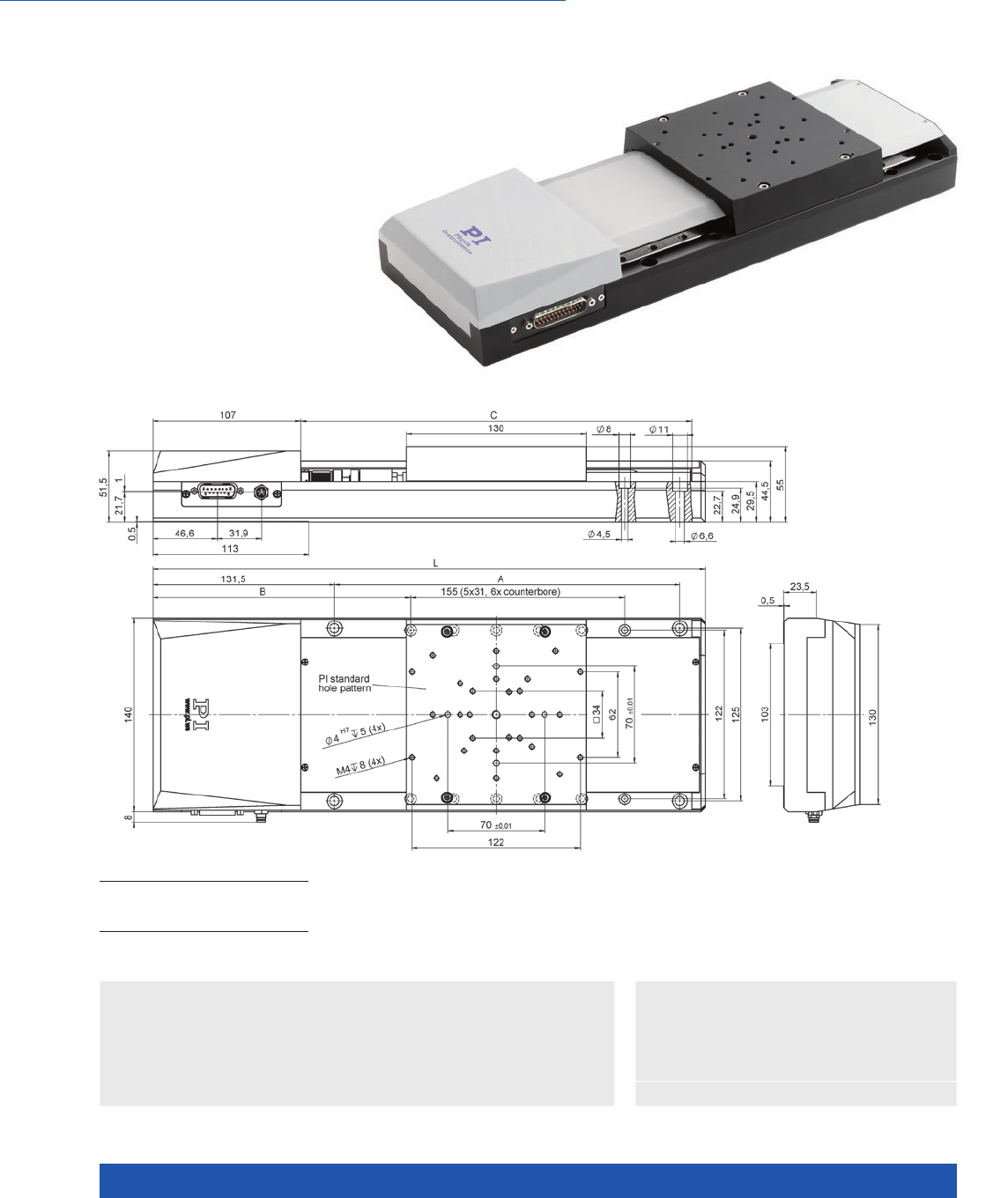
WWW.PI.WS
106
High Travel Accuracy, Long Travel Ranges, Many Motor Variants
M-511 / M-521 / M-531
High-Precision Linear Stage
>> ActiveDrive
>> Linear Encoder
Technology Glossary ...................... page 290
Applications
n Metrology / Testing
n Optical Alignment
n Photonics
n Sample Inspection
n Scientific Instrumentation
n Travel ranges 102, 204, and 306 mm
(4”, 8”, 12”)
n Max. velocity to 100 mm/s
n Encoder resolution 50 nm
n Load capacity to 100 kg
n Zero-play ball screw
n XY and XYZ combinations
M-511, M-521, M-531, dimensions in mm
L A B C
M- 511.xx1
M-521.xx1
M-531.xx1
400
500
600
250
350
450
186,5
236,5
286,5
283
383
483

MOTION | POSITIONING
107
M-5x1.DD1 /
M-5x1.DD2
M-5x1.EC /
M-5x1.PD1
M-5x1.DG1 /
M-5x1.PG1
Unit Tolerance
Motion and positioning
Travel range M-511: 102 (4”) /
M-521: 204 (8”) /
M-531: 306 (12”)
M-511: 102 (4”) /
M-521: 204 (8”) /
M-531: 306 (12”)
M-511: 102 (4”) /
M-521: 204 (8”) /
M-531: 306 (12”)
mm
Integrated sensor Linear encoder Rotary encoder Rotary encoder
Sensor resolution linear
encoder
0.05 µm
Sensor resolution rotary
encoder
– 4096 2048 Cts./rev.
Design resolution 0.05 0.488 0.033 µm typ.
Minimum incremental
motion
0.1 0.5 0.4 µm typ.
Unidirectional
repeatability
0.1 0.5 0.4 µm typ.
Bidirectional repeatability ±0.2 – – µm typ.
Backlash – 1 1 µm typ.
Pitch / yaw per 100 mm ±35 ±35 ±35 µrad typ.
Straightness / flatness
per 100 mm
111µm
Velocity 50 100 6 mm/s max.
Mechanical properties
Drive screw pitch of ball
screw
222mm
Gear ratio – – (28/12)4 ~ 29.6:1
Load capacity 1000 1000 1000 N max.
Push/pull force 80 80 80 N max.
Permissible lateral force 200 200 200 N max.
Drive properties
Motor type DC motor with PWM
control
DC motor with PWM
control*
DC gear motor
Motor resolution – – – steps/rev.
Guide Recirculating ball
bearings
Recirculating ball
bearings
Recirculating ball
bearings
Operating voltage 24 24 M-5x1.DG1: 0 to ±12
M-5x1.PG1: 24
V
Motor power 30 60 3 W nom.
Torque 80 70 5 mN·m nom.
Reference and limit
switches
Hall effect Hall effect Hall effect
Miscellaneous
Operating temperature
range
10 to 50 –20 to 65 –20 to 65 °C
Material Aluminum,
black anodized
Mass 5 (M-511) /
6.1 (M-521) /
7.2 (M-531)
5 (M-511) /
6.1 (M-521) /
7.2 (M-531)
5 (M-511) /
6.1 (M-521) /
7.2 (M-531)
kg ±5 %
Connector Sub-D 15,
3 m incl. cable
Sub-D 15,
3 m incl. cable
Sub-D 15,
3 m incl. cable
Recommended
controllers
C-863
C-884
C-863
C-884
C-863
C-884
* M-5xx.EC: Brushless DC motor with integrated block commutation (PWM control).
Ask about custom designs!
Translation Stages
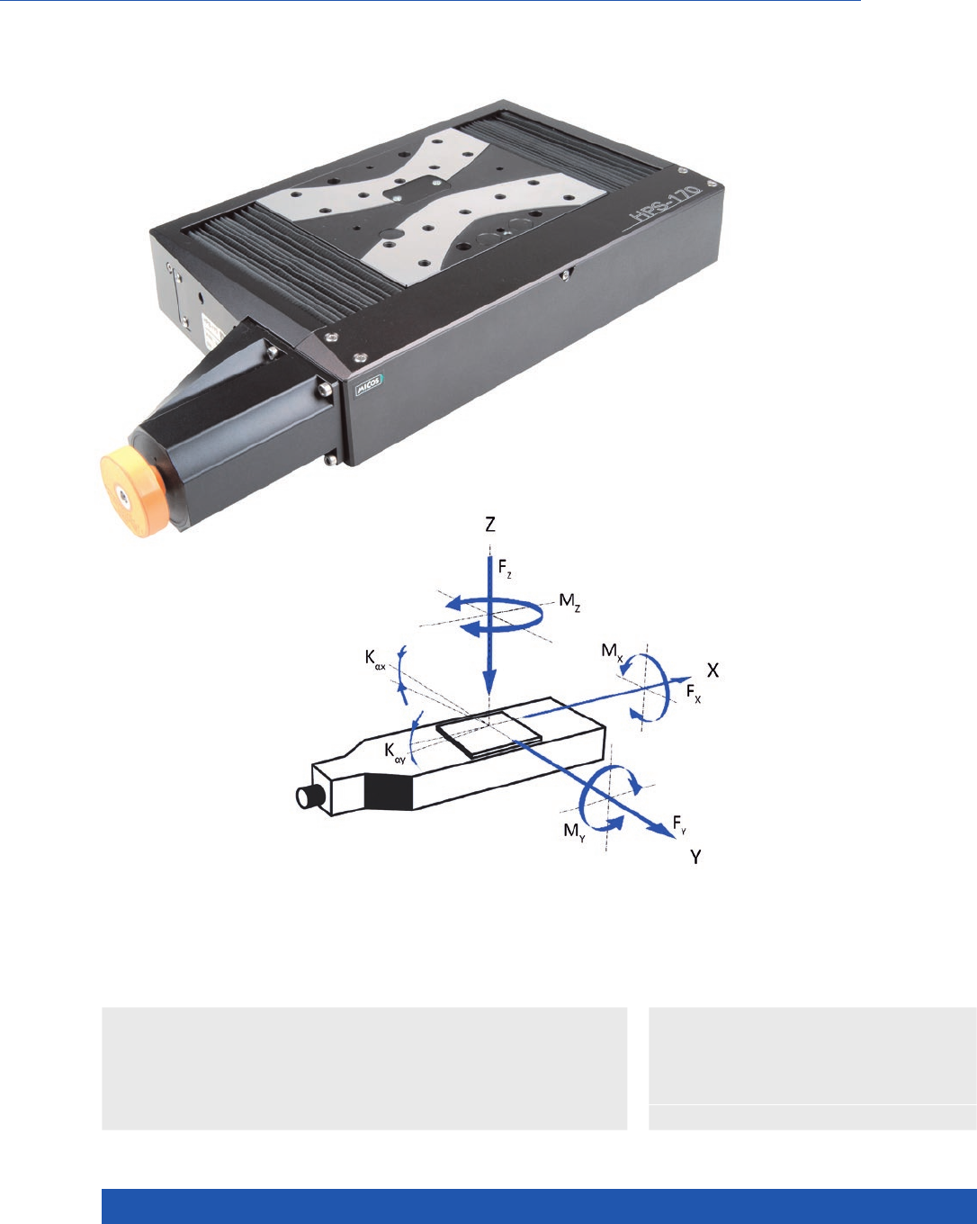
WWW.PI.WS
108
Excellent Repeatability and Travel Accuracy
HPS-170
High-Precision Linear Stage for Heavy Loads
>> ActiveDrive
>> Linear Encoder
Technology Glossary ...................... page 290
Applications
n Laser Marking
n Metrology / Testing
n Sample Inspection
n Semiconductor
n Travel ranges from 52 to 205 mm
(2 to 8”)
n Max. velocity to 100 mm/s
n Load capacity to 35 kg
n Optional linear encoder for direct
position measurement
n Crossed roller guide, anti-creep
Direction of the axes
and torques for linear stages

MOTION | POSITIONING
109
626291x00 626291x10 626292x00 626292x10-0001 Unit Tolerance
Linear stage with
DC motor and
rotary encoder
Additionally with
linear encoder
Linear stage with
stepper motor
Additionally with
linear encoder
Active axes X X
Motion and positioning
Travel range 52 / 102 / 155 /
205
52 / 102 / 155 /
205
mm
Integrated sensor Rotary encoder Rotary and linear
encoder
– Linear encoder
Sensor signal rotary
encoder
A/B quadrature,
RS-422
A/B quadrature,
RS-422
–
Sensor signal linear
encoder
– A/B quadrature,
RS-422
–Sin/cos, 1 V
peak-peak, 20 µm
signal period
Design resolution 0.1 0.05 10 (full step) 0.005 µm
Sensor resolution rotary
encoder
20000 20000 – Cts./rev.
Sensor resolution
linear encoder
– 0.05 – – µm typ.
Minimum incremental
motion
0.2 0.2 0.2 0.05 µm typ.
Unidirectional
repeatability
0.2 0.2 0.2 0.05 µm typ.
Bidirectional
repeatability
±2 ±0.2 ±2 ±0.05 µm typ.
Pitch ±20 / ±25 / ±30 /
±35
±20 / ±25 / ±30 /
±35
±20 / ±25 / ±30 /
±35
±20 / ±25 / ±30 /
±35
µrad typ.
Yaw ±40 ±40 ±40 ±40 µrad typ.
Straightness / flatness ±0.75 / ±1 / ±2 /
±3
±0.75 / ±1 / ±2 /
±3
±0.75 / ±1 / ±2 /
±3
±0.75 / ±1 / ±2 /
±3
µrad typ.
Max. velocity 100 100 35 35 mm/s
Mechanical properties
Guide type Crossed roller
guide with anti-
creep system
Crossed roller
guide with anti-
creep system
Crossed roller
guide with anti-
creep system
Crossed roller
guide with anti-
creep system
Drive screw type Ball screw Ball screw Ball screw Ball screw
Drive screw pitch 2 2 2 2 mm
Load capacity 350 350 350 350 N max.
Push/pull force 100 100 150 150 N max.
Holding force 20 20 60 60 N max.
Permissible lateral force 150 150 150 150 N max.
Permissible torque Mx
in θX
400 400 400 400 Nm max.
Permissible torque My
in θY
300 300 300 300 Nm max.
Permissible torque Mz
in θZ
300 300 300 300 Nm max.
Drive properties
Motor type DC motor DC motor 2-phase stepper
motor
2-phase stepper
motor
Operating voltage,
nominal
24 24 24 24 V nom.
Operating voltage, max. 48 48 48 48 V nom.
Peak current, effective 3.8 3.8 1.2 1.2 A typ.
Torque constant,
effective
0.03 0.03 N·m/A typ.
Electrical time constant 6 6 ms
Resistance phase-phase 0.62 0.62 3.3 3.3 Ω typ.
Inductance phase-phase 0.13 0.13 2.8 2.8 mH typ.
Back EMF phase-phase 0.00349 0.00349 V/kRPM max.
Limit switches mechanical mechanical mechanical mechanical
Translation Stages
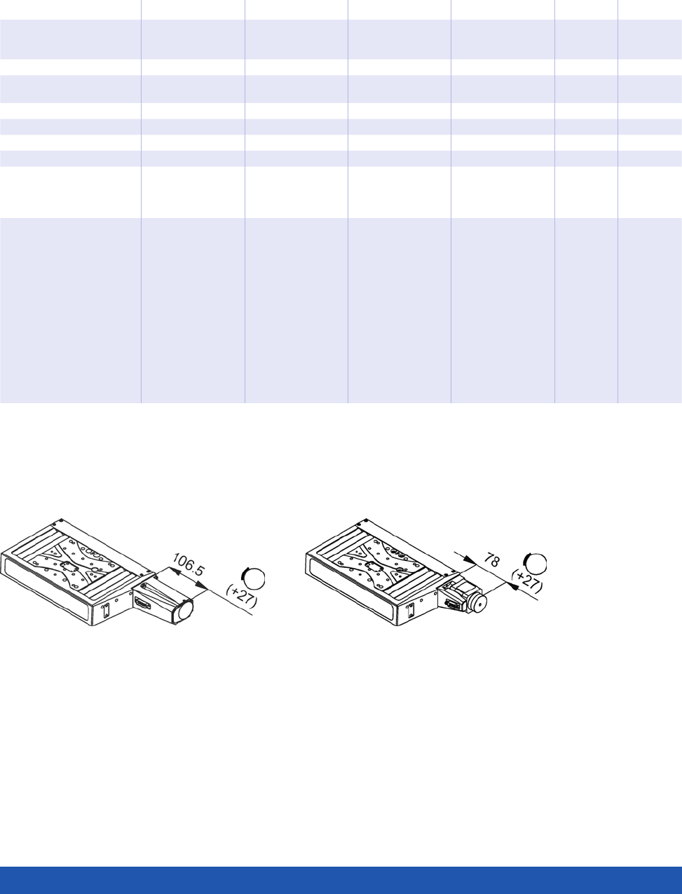
WWW.PI.WS
110
Connecting cables for motor and sensor are not in the scope of delivery and must be ordered separately.
Ask about custom designs!
626291x00 626291x10 626292x00 626292x10-0001 Unit Tolerance
Linear stage with
DC motor and
rotary encoder
Additionally with
linear encoder
Linear stage with
stepper motor
Additionally with
linear encoder
Miscellaneous
Operating temperature
range
5 to 40 5 to 40 5 to 40 5 to 40 °C
MTBF 10000 10000 ––h
Material Aluminum, steel Aluminum, steel Aluminum, steel Aluminum, steel
Mass 5.1 / 5.8 / 6.6 / 7.5 5.1 / 5.8 / 6.6 / 7.5 5 / 5.7 / 6.5 / 7.4 5 / 5.7 / 6.5 / 7.4 kg ±5 %
Moved mass 1.1 1.4 1.1 1.4
Connection Sub-D 15 (m) Motor:
Sub-D 15 (m)
Sensor:
Sub-D 9 (m)
Sub-D 15 (m) Motor:
Sub-D 15 (m)
Sensor:
Sub-D 9 (m)
Recommended
controllers
C-863
(single axis)
with C-863.AD12
line driver
C-884
(to 6 axes) with
C-863.AD12
line driver
C-885 with
C-863.20C885
(to 40 axes)
and C-863.AD12
line driver
ACS modular
controller
C-863
(single axis)
with C-863.AD12
line driver
C-884
(to 6 axes) with
C-863.AD12
line driver
C-885 with
C-863.20C885
(to 40 axes)
and C-863.AD12
line driver
ACS modular
controller
C-663.12
(single axis)
SMC Hydra
(double axis)
C-885 with
C-663.12C885
(up to 20 axes)
ACS modular
controller
C-663.12
(single axis)
SMC Hydra
(double axis
C-885 with
C-663.12C885
(up to 20 axes)
ACS modular
controller
HPS-170, stepper motor, dimensions in mmHPS-170, DC motor, dimensions in mm
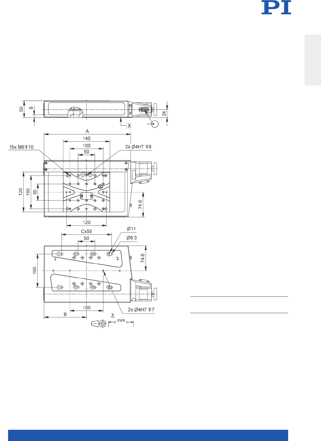
MOTION | POSITIONING
111
Travel range/mm 52 102 155 205
A/mm
B/mm
C/mm
261
127.5
3
311
152.5
3
381
187.5
3
456
225
6
HPS-170, dimensions in mm
Translation Stages
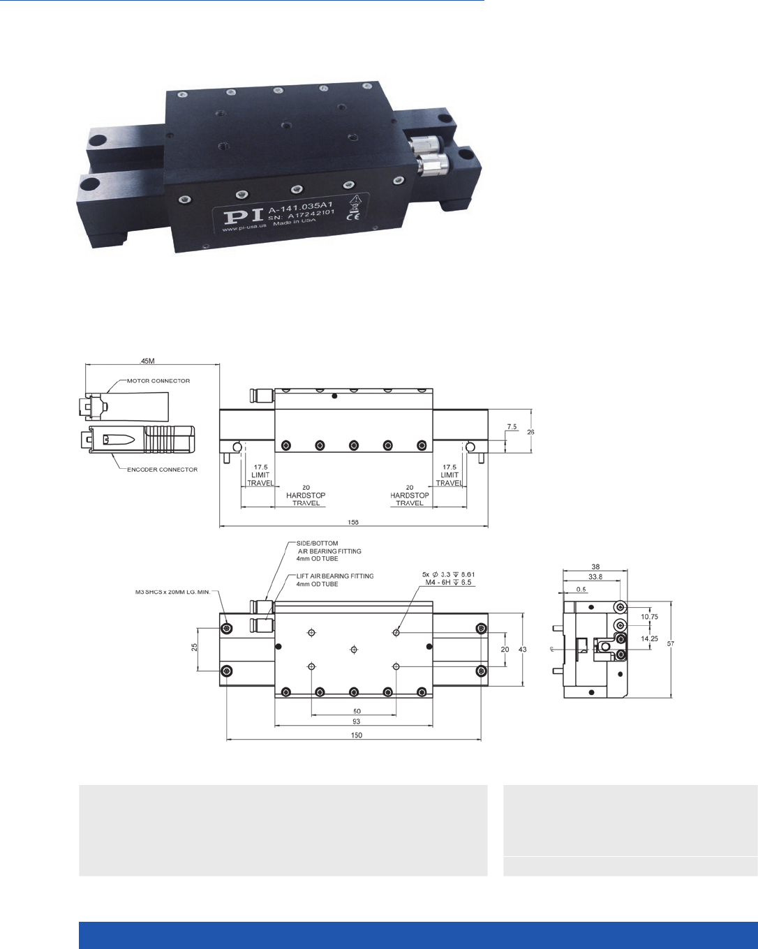
WWW.PI.WS
112
High Performance, Cleanroom Compatible, Customizable
A-141 PIglide MB Miniature
Linear Stage with Air Bearings
n Size of the motion platform 57 mm × 93 mm
n Low profile 38 mm
n Travel ranges to 35 mm
n Load capacity to 3 kg
n Velocity to 0.25 m/sec
n Acceleration to 3.5 m/s²
>> Air bearings
>> Linear encoder
>> Linear motor
Technology Glossary ...................... page 290
Applications
n Precision Micro Assembly
n Scanning
n Photonics
n Optical Alignment
A-141.035A1, dimensions in mm
Accessories and options
n PIglide filter and air preparation kits
n Single and multi-axis motion controller
n XY setups and individual configurations
n Counterbalance options for vertical (Z)
orientations
n Base plates made of granite and systems
for reducing vibration

MOTION | POSITIONING
113
A-141 Unit Tolerance
Motion
Active axes X
Travel range 35 mm
Pitch / yaw (1)
over the entire travel range
10 µrad max.
Straightness / flatness (1)
over the entire travel range
0.5 µm max.
Velocity (2), unloaded 0.25 m/s max.
Acceleration (2), unloaded 3.5 m/s² max.
Mechanical properties
Load capacity in z (3) 3kg max.
Moved mass 0.3 kg
Overall mass 0.6 kg
Guide type Air bearing
Drive properties
Drive type Linear motor, ironless, 3-phase
Intermediate circuit voltage, effective 48, nominal
80, max.
V DC
Peak force 2.3 N typ.
Nominal force 0.58 N typ.
Force constant, effective 2.1 N/A typ.
Resistance phase-phase 22.4 Ω typ.
Inductivity phase-phase 1.0 mH typ.
Back EMF phase-phase 0.7 V·s/m max.
Cabling Internal, no moving cable
Positioning
Integrated sensor Incremental linear encoder with travel range limits
and home index
Sensor signal Sin/cos, 1 V peak-peak, 20 µm signal period
Sensor resolution 1.2 nm (4)
Bidirectional repeatability ±0.1 µm (4)
Accuracy, uncompensated (5) ±2.0 µm
Accuracy, with error compensation (5) ±0.25 µm
Miscellaneous
Operating pressure (6) 65±5 psi (450±35 kPa)
Air consumption <1.0 SCFM (28 SLPM)
Air quality Clean (unfiltered to 1.0 µm or better) – ISO 8573-1 class 1
Oil free – ISO 8573-1 class 1
Dry (–15 °C dew point) – ISO 8573-1 class 3
Materials Hardcoat aluminum, stainless steel fasteners
(1) Dependent on the flatness of the surface, on which the stage is mounted.
(2) Can be limited by the payload, controller or drive.
(3) Assumes payload CG is centered no more than 50 mm above the motion platform. The stage is designed for horizontal operation only.
(4) Assumes 16384x interpolation. Contact PI for the use of other factors.
(5) Improved accuracy can be obtained with controller-based error compensation. The stage must be ordered with a controller from PI to reach these values.
Accuracy values assume short-term duration and do not consider the long-term effects of thermal drift on the stage.
(6) To protect the stage against damage, it is recommended to connect an air pressure sensor to the E-Stop input of the controller.
Translation Stages
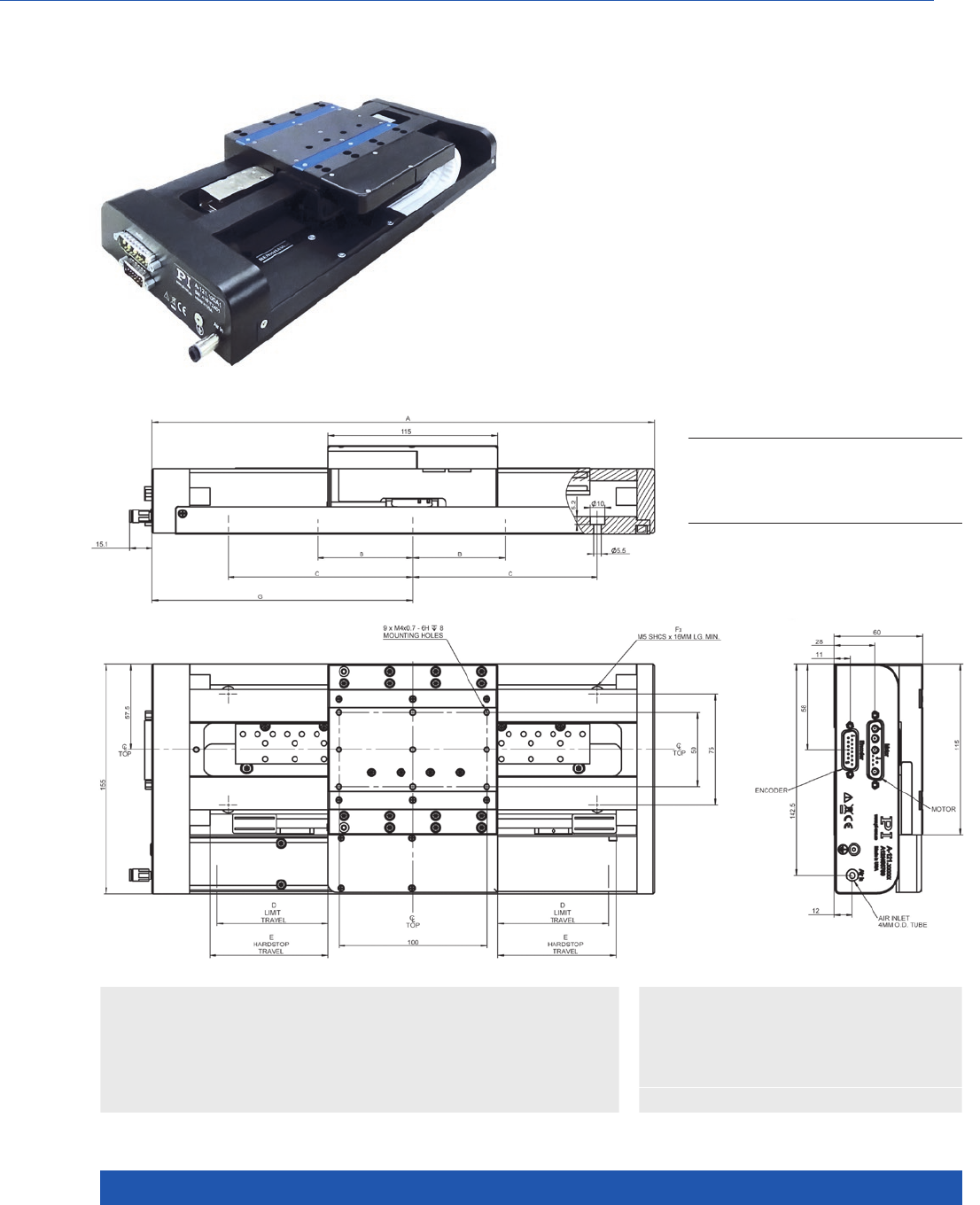
WWW.PI.WS
114
n Ideal for scanning applications
or high-precision positioning
n Cleanroom compatible
n Size of the motion platform
115 mm × 115 mm
n Travel ranges to 350 mm
n Low profile from 60 mm
n Resolution to 1 nm
n Best flatness / straightness
n Counterbalance options for
vertical assembly
>> Air bearings
>> Linear encoder
>> Linear motor
Technology Glossary ...................... page 290
Applications
n Sample Inspection
n Scanning
n Metrology / Testing
n Photonics
n Flatpanel Inspection
MODEL A B C D E F G
A-121.050
A-121.10 0
A-121.150
A-121.200
A-121.250
A-121.350
240
290
340
390
440
540
100
75
100
125
150
150
200
25
50
75
100
125
175
30
55
80
105
130
180
4
4
6
6
6
10
126.5
151.5
176.5
201.5
226.5
276.5
High Performance Small Footprint Nanopositioning Stage
A-121 PIglide AT1 Linear Stage with Air Bearings
A-121, dimensions in mm

MOTION | POSITIONING
115
A-121.050 A-121.100 A-121.150 A-121.200 A-121.250 A-121.350 Unit Tolerance
Motion
Active axes X X X X X X
Travel range 50 100 150 200 250 350 mm
Pitch / yaw (1) 12 12 15 20 25 35 µrad max.
Straightness / flatness (1) ±0.5 ±0.5 ±0.5 ±0.75 ±0.75 ±1.25 µm max.
Straightness / flatness
per 25 mm travel range (1)
0.1 0.1 0.1 0.1 0.1 0.1 µm max.
Velocity, unloaded (2) 1 1 1 1 1 1 m/s max.
Acceleration, unloaded (2) 20 20 20 20 20 20 m/s² max.
Mechanical properties
Load capacity in z (3) 100 100 10 0 100 100 100 N max.
Load capacity in y (3) 40 40 40 40 40 40 N max.
Moved mass 1.2 1.2 1.2 1.2 1.2 1.2 kg
Overall mass 3.5 4.2 4.5 5.2 5.7 6.8 kg
Guide type
Air bearing Air bearing Air bearing Air bearing Air bearing Air bearing
A-121 Unit Tolerance
Drive properties
Drive type Linear motor, ironless, 3-phase
Intermediate circuit voltage,
effective
48, nominal
80, max.
V DC
Peak force 33.2 N typ.
Nominal force 11. 1 N typ.
Force constant, effective 6.67 N/A typ.
Resistance phase-phase 6.3 Ω typ.
Inductivity phase-phase 1.0 mH typ.
Back EMF phase-phase 7. 7 V·s/m max.
Cabling External, moving cable
A-121.xxxA A-121.xxxB A-121.xxxC
Positioning
Integrated Sensor Incremental linear encoder Absolute encoder Incremental linear encoder
Sensor signal Sin/cos, 1 V peak-peak,
20 µm signal period
BiSS-C A/B quadrature, TTL
Sensor resolution 1.2 nm (4) 1 nm 50 nm
Bidirectional repeatability A-121.050: ±0.25 µm (4)
A-121.100: ±0.25 µm (4)
A-121.150: ±0.25 µm (4)
A-121.200: ±0.25 µm (4)
A-121.250: ±0.25 µm (4)
A-121.350: ±0.50 µm (4)
A-121.050: ±0.25 µm
A-121.100: ±0.25 µm
A-121.150: ±0.25 µm
A-121.200: ±0.25 µm
A-121.250: ±0.25 µm
A-121.350: ±0.50 µm
A-121.050: ±0.25 µm
A-121.100: ±0.25 µm
A-121.150: ±0.25 µm
A-121.200: ±0.25 µm
A-121.250: ±0.25 µm
A-121.350: ±0.50 µm
Accuracy, uncompensated (5) A-121.050: ±1.0 µm
A-121.100: ±1.0 µm
A-121.150: ±1.5 µm
A-121.200: ±2.0 µm
A-121.250: ±2.0 µm
A-121.350: ±3.0 µm
A-121.050: ±1.5 µm
A-121.100: ±1.5 µm
A-121.150: ±1.5 µm
A-121.200: ±1.5 µm
A-121.250: ±1.5 µm
A-121.350: ±1.5 µm
A-121.050: ±1.0 µm
A-121.100: ±1.0 µm
A-121.150: ±1.5 µm
A-121.200: ±2.0 µm
A-121.250: ±2.0 µm
A-121.350: ±3.0 µm
Accuracy, with error
compensation (5)
A-121.050: ±0.50 µm
A-121.100: ±0.50 µm
A-121.150: ±0.50 µm
A-121.200: ±0.50 µm
A-121.250: ±0.50 µm
A-121.350: ±1.0 µm
A-121.050: ±0.5 µm
A-121.100: ±0.5 µm
A-121.150: ±0.5 µm
A-121.200: ±0.5 µm
A-121.250: ±0.5 µm
A-121.350: ±0.5 µm
A-121.050: ±0.50 µm
A-121.100: ±0.50 µm
A-121.150: ±0.50 µm
A-121.200: ±0.50 µm
A-121.250: ±0.50 µm
A-121.350: ±1.0 µm
A-121
Miscellaneous
Operating pressure (6) 65 to 75 psi (450 to 520 kPa)
Air consumption <1.0 SCFM (28 SLPM)
Air quality Clean (filtered to 1.0 µm or better) – ISO 8573-1 Class 1
Oil free – ISO 8573-1 Class 1
Dry (–15 °C dew point) – ISO 8573-1 Class 3
Materials Hardcoat aluminum, stainless steel fasteners
(1) Dependent on the flatness of the surface, on which the stage is mounted.
(2) Can be limited by the payload, controller or drive.
(3) Assumes payload CG is centered no more than 50 mm above the motion
platform.
(4) Assumes 16384x interpolation. Contact PI for the use of other factors.
(5) Improved accuracy can be obtained with controller-based error compensation.
The stage must be ordered with a controller from PI to reach these values.
Accuracy values assume short-term duration and do not consider the long-term
effects of thermal drift on the stage.
(6) To protect the stage against damage, it is recommended to connect
an air pressure sensor to the Motion-Stop input of the controller.
Translation Stages
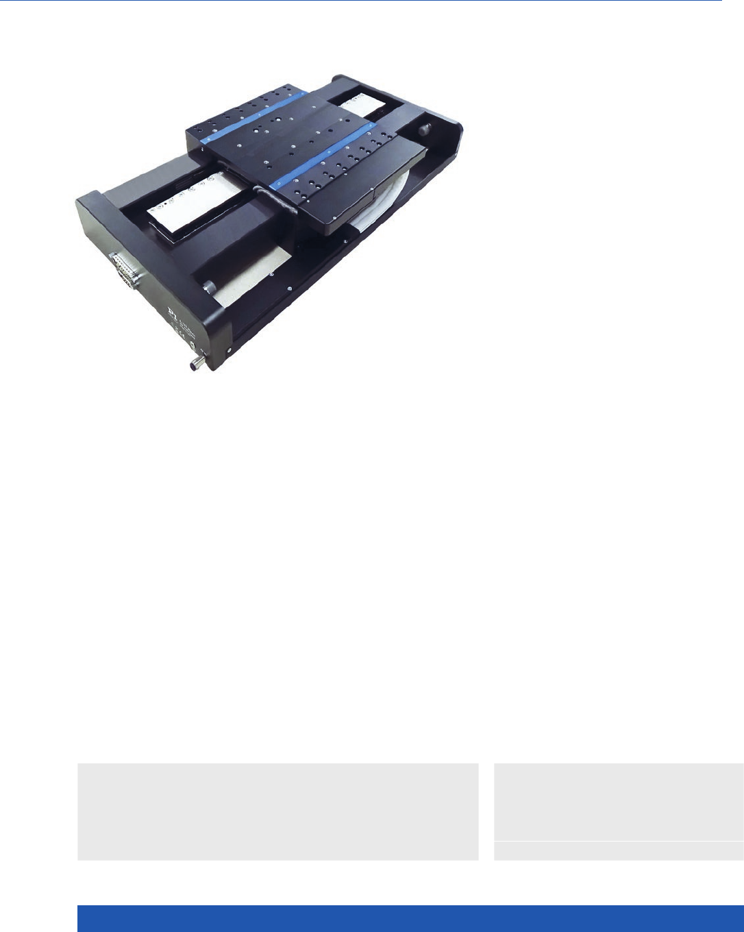
WWW.PI.WS
116
n Ideal for scanning applications or high-
precision positioning
n Cleanroom compatible
n Size of the motion platform 210 mm × 210 mm
n Travel ranges 50 mm to 750 mm
n Resolution to 1 nm
>> Air bearings
>> Linear encoder
>> Linear motor
Technology Glossary ...................... page 290
Applications
n Sample Inspection
n Scanning
n Metrology / Testing
n Photonics
n Flatpanel Inspection
High Performance Nanopositioning Stage
A-123 PIglide AT3 Linear Stage with Air Bearings
Product Overview
The stages in the PIglide are equipped with a servo drive linear motor with
preloaded air bearings and integrated linear encoder. The combination of these
noncontact components results in a frictionless motion platform that offers
the highest performance, quality, and lifetime. A high-force linear motor can
drive the stage to top speed within a few milliseconds, and the high-capacity
bearings can support payloads up to 60 kg. The laterally opposed, actively
preloaded air bearing design in this model allows mounting in any orientation.
Application fields
PIglide positioning systems are ideally suited for many high-precision appli-
cations such as metrology, photonics, and precision scanning in semiconduc-
tor or flat panel display manufacturing. Thanks to the friction-free motion,
no particles are formed, which makes PIglide stages ideal for cleanroom appli-
cations.
Accessories and options
n Encoder
n PIglide filter and air preparation kits
n Single and multi-axis motion controller
n XY setups and individual configurations
n Cable track variations
n Options with counterweight for vertical (Z)
orientation
n Customizations available
n Base plates made of granite and systems
for reducing vibration

MOTION | POSITIONING
117
A-123.050 A-123.100 A-123.150 A-123.200 A-123.350 A-123.500 A-123.750 Unit Tolerance
Motion
Active axes X X X X X X X
Travel range 50 100 150 200 350 500 750 mm
Pitch / yaw (1) 510 15 15 20 25 35 µrad max.
Straightness /
flatness (1)
±0.5 ±0.5 ±0.5 ±1 ±1.5 ±1.5 ±2.5 µm max.
Straightness /
flatness per
25 mm travel
range (1)
0.1 0.1 0.1 0.1 0.1 0.1 0.1 µm max.
Velocity,
unloaded (2)
1 1 1 1 1 1 1 m/s max.
Acceleration,
unloaded (2)
30 30 30 30 30 30 30 m/s² max.
Mechanical
properties
Load capacity
in z (3)
590 590 590 590 590 590 590 N max.
Load capacity
in y (3)
295 295 295 295 295 295 295 N max.
Moved mass 5 5 5 5 5 5 5 kg
Overall mass 14 15.5 16.5 18 21.5 25 32 kg
Guide type
Air bearing Air bearing Air bearing Air bearing Air bearing Air bearing Air bearing
A-123 Unit Tolerance
Drive properties
Drive type Linear motor, ironless, 3-phase
Intermediate circuit
voltage, effective
48, nominal
80, max.
V DC
Peak force 298 N typ.
Nominal force 87.5 N typ.
Force constant, effective 19.9 N/A typ.
Resistance phase-phase 3.6 Ω typ.
Inductivity phase-phase 1.2 mH typ.
Back EMF phase-phase 16 V·s/m max.
Cabling External, moving cable
Translation Stages

WWW.PI.WS
118
(1) Dependent on the flatness of the surface, on which the stage is mounted.
(2) Can be limited by the payload, controller or drive.
(3) Assumes payload CG is centered no more than 50 mm above the motion platform.
(4) Assumes 16384x interpolation. Contact PI for the use of other factors.
(5) Improved accuracy can be obtained with controller-based error compensation. The stage must be ordered with a controller from PI to reach these values.
Accuracy values assume short-term duration and do not consider the long-term effects of thermal drift on the stage.
(6) To protect the stage against damage, it is recommended to connect an air pressure sensor to the Motion-Stop input of the controller.
A 123.xxxA A 123.xxxB A 123.xxxC
Positioning
Integrated Sensor Incremental linear encoder Absolute encoder Incremental linear encoder
Sensor signal Sin/cos, 1 V peak-peak,
20 µm signal period
BiSS-C A/B quadrature, TTL
Sensor resolution 1.2 nm (4) 1 nm 50 nm
Bidirectional repeatability A-123.050: ±0.25 µm (4)
A-123.100: ±0.25 µm (4)
A-123.150: ±0.25 µm (4)
A-123.200: ±0.25 µm (4)
A-123.350: ±0.5 µm (4)
A-123.500: ±0.5 µm (4)
A-123.750: ±0.75 µm (4)
A-123.050: ±0.25 µm
A-123.100: ±0.25 µm
A-123.150: ±0.25 µm
A-123.200: ±0.25 µm
A-123.350: ±0.5 µm
A-123.500: ±0.5 µm
A-123.750: ±0.75 µm
A-123.050: ±0.25 µm
A-123.100: ±0.25 µm
A-123.150: ±0.25 µm
A-123.200: ±0.25 µm
A-123.350: ±0.5 µm
A-123.500: ±0.5 µm
A-123.750: ±0.75 µm
Accuracy,
uncompensated (5)
A-123.050: ±1 µm
A-123.100: ±1 µm
A-123.150: ±1.5 µm
A-123.200: ±2 µm
A-123.350: ±3 µm
A-123.500: ±3.5 µm
A-123.750: ±5 µm
A-123.050: ±1.5 µm
A-123.100: ±1.5 µm
A-123.150: ±1.5 µm
A-123.200: ±1.5 µm
A-123.350: ±1.5 µm
A-123.500: ±1.5 µm
A-123.750: ±1.5 µm
A-123.050: ±1 µm
A-123.100: ±1 µm
A-123.150: ±1.5 µm
A-123.200: ±2 µm
A-123.350: ±3 µm
A-123.500: ±3.5 µm
A-123.750: ±5 µm
Accuracy, with error
compensation (5)
A-123.050: ±0.5 µm
A-123.100: ±0.5 µm
A-123.150: ±0.5 µm
A-123.200: ±0.5 µm
A-123.350: ±1 µm
A-123.500: ±1 µm
A-123.750: ±1.5 µm
A-123.050: ±1.5 µm
A-123.100: ±1.5 µm
A-123.150: ±1.5 µm
A-123.200: ±1.5 µm
A-123.350: ±1.5 µm
A-123.500: ±1.5 µm
A-123.750: ±1.5 µm
A-123.050: ±0.5 µm
A-123.100: ±0.5 µm
A-123.150: ±0.5 µm
A-123.200: ±0.5 µm
A-123.350: ±1 µm
A-123.500: ±1 µm
A-123.750: ±1.5 µm
A-123
Miscellaneous
Operating pressure (6) 75 to 85 psi (515 to 585 kPa)
Air consumption <1.0 SCFM (28 SLPM)
Air quality Clean (filtered to 1.0 µm or better) – ISO 8573-1 Class 1
Oil free – ISO 8573-1 Class 1
Dry (–15 °C dew point) – ISO 8573-1 Class 3
Materials Hardcoat aluminum, stainless steel fasteners
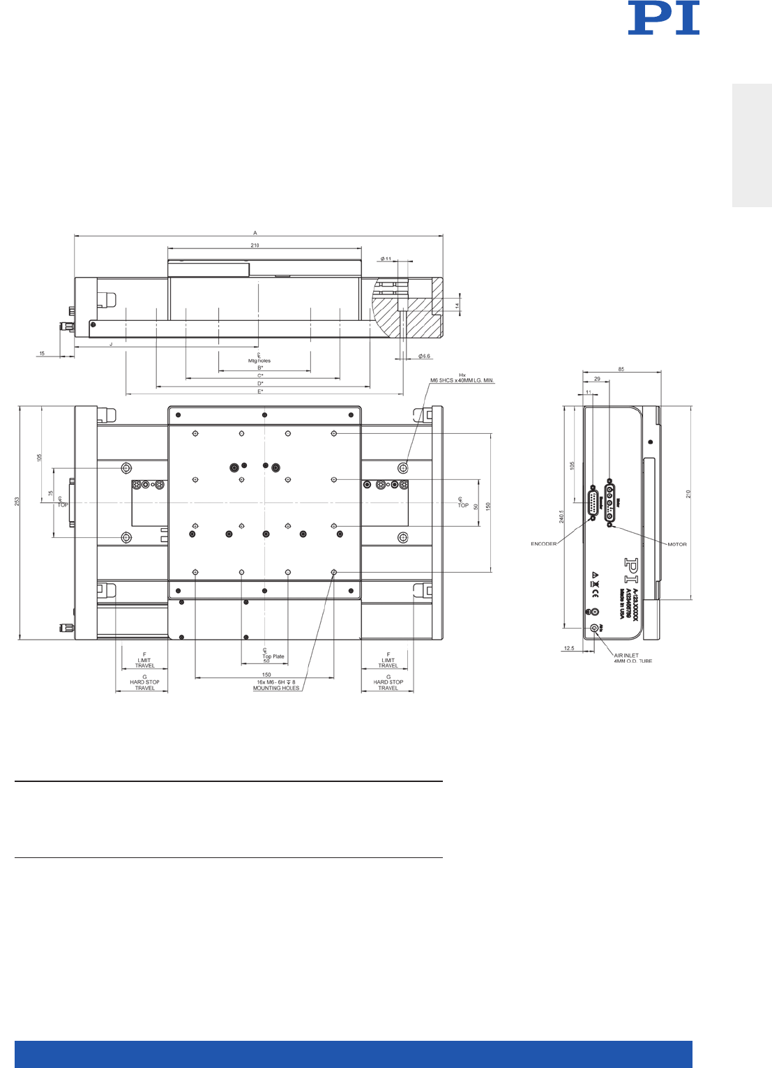
MOTION | POSITIONING
119
A-123, dimensions in mm
* The mounting holes are symmetric around the center line located at “J”
MODEL A B* C* D* E* F G Hx J Moving Mass Total Mass
A-123.050
A-123.100
A-123.150
A-123.200
A-123.350
A-123.500
A-123.750
350
400
450
500
650
800
1050
100
100
100
100
100
100
325
300
400
500
700
250
300
350
400
550
700
1000
25
50
75
100
175
250
375
31.5
56.5
81.5
106.5
181.5
256.5
381.5
4
8
8
8
12
16
16
181.5
206.5
231.5
256.5
331.5
406.5
531.5
5 kg
5 kg
5 kg
5 kg
5 kg
5 kg
5 kg
14 kg
15.5 kg
16.5 kg
18 kg
21.5 kg
25 kg
32 kg
Translation Stages
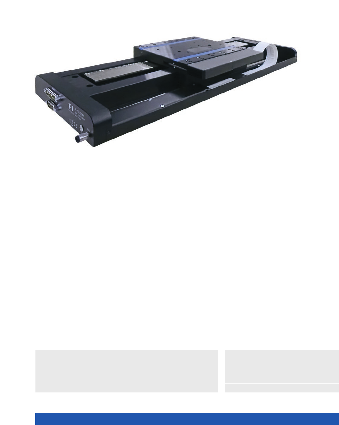
WWW.PI.WS
120
High-Performance Nanopositioning System for a Good Price
A-110 PIglide LC Linear Stage with Air Bearings
>> Air bearings
>> Linear encoder
>> Linear motor
Technology Glossary ...................... page 290
Applications
n Sample Inspection
n Scanning
n Metrology / Testing
n Photonics
n Flatpanel Inspection
n Ideal for scanning applications or high-precision
positioning
n Cleanroom compatible
n Size of the motion platform 160 mm × 200 mm
n Travel ranges to 400 mm
n Load capacity to 100 N
n Best flatness / straightness
Product Overview
PIglide positioning systems have a magnetic linear
motor, magnetically preloaded air bearings and
an optical linear encoder: Noncontact and friction-
free motion for the highest accuracy and reliability.
Accessories and options
n Encoder
n PIglide Filter and Air Preparation Kits
n Single and multi-axis motion controller
n XY setups and individual configurations
n Base plates made of granite and systems
for reducing vibration

MOTION | POSITIONING
121
A-110.050xx A-110.100xx A-110.200xx A-110.300xx A-110.400xx Unit Tolerance
Motion
Active axes X X X X X
Travel range 50 100 200 300 400 mm
Pitch / yaw (1) 10 20 30 40 50 µrad max.
Straightness / flatness (1) ±1 ±1 ±1.5 ±2 ±2.5 µm max.
Straightness / flatness
per 10 mm travel range (1)
±10 ±10 ±10 ±10 ±10 nm max.
Velocity, unloaded (2) 0.5 0.5 1 1 1 m/s max.
Acceleration, unloaded (2) 10 10 30 30 30 m/s² max.
Mechanical properties
Load capacity in z (3) 100 100 100 100 100 N max.
Moved mass 2.5 2.5 2.6 2.6 2.6 kg
Overall mass 6.3 7. 5 11 12 14 kg
Guide type Air bearing Air bearing Air bearing Air bearing Air bearing
A-110.050xx
A-110.100xx
A-110.200xx
A-110.300xx
A-110.400xx
Unit Tolerance
Drive properties
Drive type Linear motor, ironless, 3-phase Linear motor, ironless, 3-phase
Intermediate circuit voltage,
effective
48, nominal
60, max.
48, nominal
60, max.
V DC
Peak force 25 85 N typ.
Nominal force 9.2 39 N typ.
Force constant, effective 4.2 12.3 N/A typ.
Resistance phase-phase 8.2 3.6 Ω typ.
Inductivity phase-phase 2.7 1.24 mH typ.
Back EMF phase-phase 4.2 10.1 V·s/m max.
Cabling Internal, no moving cable External, moving cable
A-110.xxxA A-110.xxxB A-110.xxxC
Positioning
Integrated Sensor Incremental linear encoder Absolute encoder Incremental linear encoder
Sensor signal Sin/cos, 1 V peak-peak,
20 µm signal period
BiSS-C A/B quadrature, TTL
Sensor resolution 1.2 nm (4) 1 nm 50 nm
Bidirectional repeatability ±0.5 µm (4) ±0.5 µm ±0.5 µm
Accuracy, uncompensated (5) A-110.050: ±1 µm
A-110.100: ±1.5 µm
A-110.200: ±2 µm
A-110.300: ±3 µm
A-110.400: ±4 µm
A-110.050: ±1.5 µm
A-110.100: ±1.5 µm
A-110.200: ±1.5 µm
A-110.300: ±1.5 µm
A-110.400: ±1.5 µm
A-110.050: ±1 µm
A-110.100: ±1.5 µm
A-110.200: ±2 µm
A-110.300: ±3 µm
A-110.400: ±4 µm
Accuracy, with error
compensation (5)
A-110.050: ±1 µm
A-110.100: ±1 µm
A-110.200: ±1 µm
A-110.300: ±1.5 µm
A-110.400: ±1.5 µm
A-110.050: ±0.5 µm
A-110.100: ±0.5 µm
A-110.200: ±0.5 µm
A-110.300: ±0.5 µm
A-110.400: ±0.5 µm
A-110.050: ±1 µm
A-110.100: ±1 µm
A-110.200: ±1 µm
A-110.300: ±1.5 µm
A-110.400: ±1.5 µm
Translation Stages
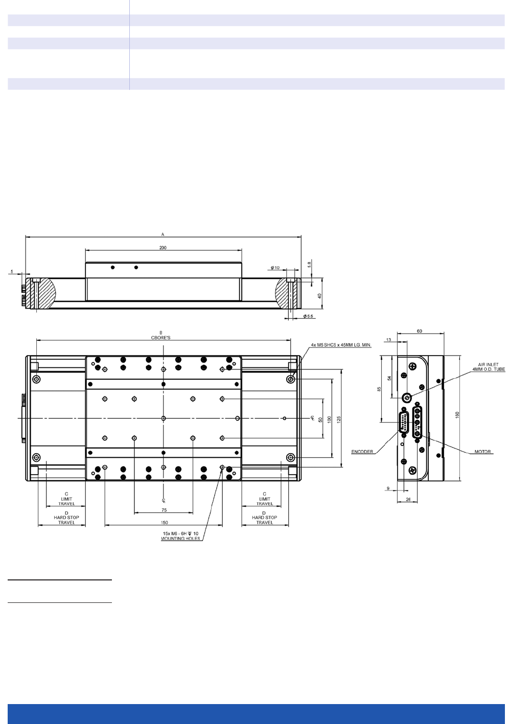
WWW.PI.WS
122
A B C D
A-110.050
A-110.100
302
352
275
325
25
50
35
60
A-110
Miscellaneous
Operating pressure (6) 60 to 70 psi (415 to 485 kPa)
Air consumption <1.0 SCFM (28 SLPM)
Air quality Clean (filtered to 1.0 µm or better) – ISO 8573-1 Class 1
Oil free – ISO 8573-1 Class 1
Dry (–15 °C dew point) – ISO 857-1 Class 3
Materials Hardcoat aluminum, stainless steel fasteners
(1) Dependent on the flatness of the surface, on which the stage is mounted.
(2) Can be limited by the payload, controller or drive.
(3) Assumes payload CG is centered no more than 50 mm above the motion platform. The stage is designed for horizontal operation only.
(4) Assumes 16384x interpolation. Contact PI for the use of other factors.
(5) Improved accuracy can be obtained with controller-based error compensation. The stage must be ordered with a controller from PI to reach
these values. Accuracy values assume short-term duration and do not consider the long-term effects of thermal drift on the stage.
(6) To protect the stage against damage, it is recommended to connect an air pressure sensor to the Motion-Stop input of the controller.
A-110.050 and A-110.100, dimensions in mm
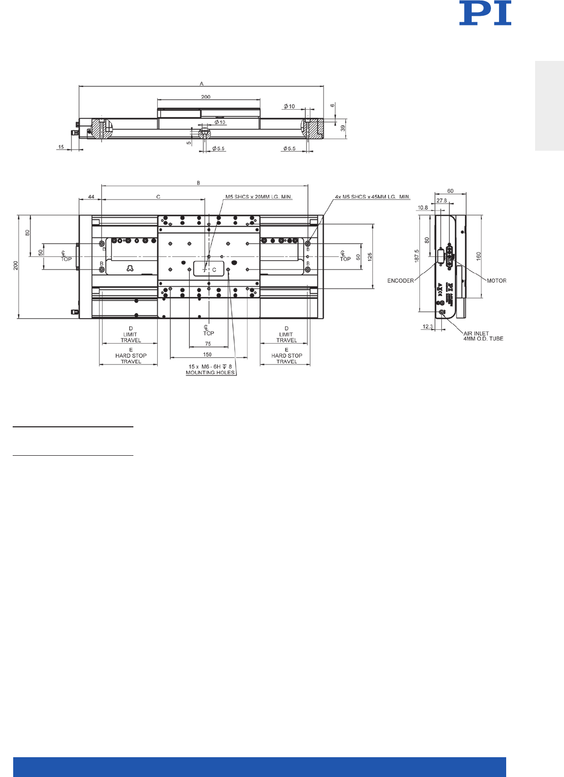
MOTION | POSITIONING
123
MODEL A B C D E
A-110.200
A-110.300
A-110- 4 0 0
475
575
675
400
500
600
200
250
300
102
152
202
105
155
205
A-110.200, A-110.300 and A-110.400, dimensions in mm
Translation Stages
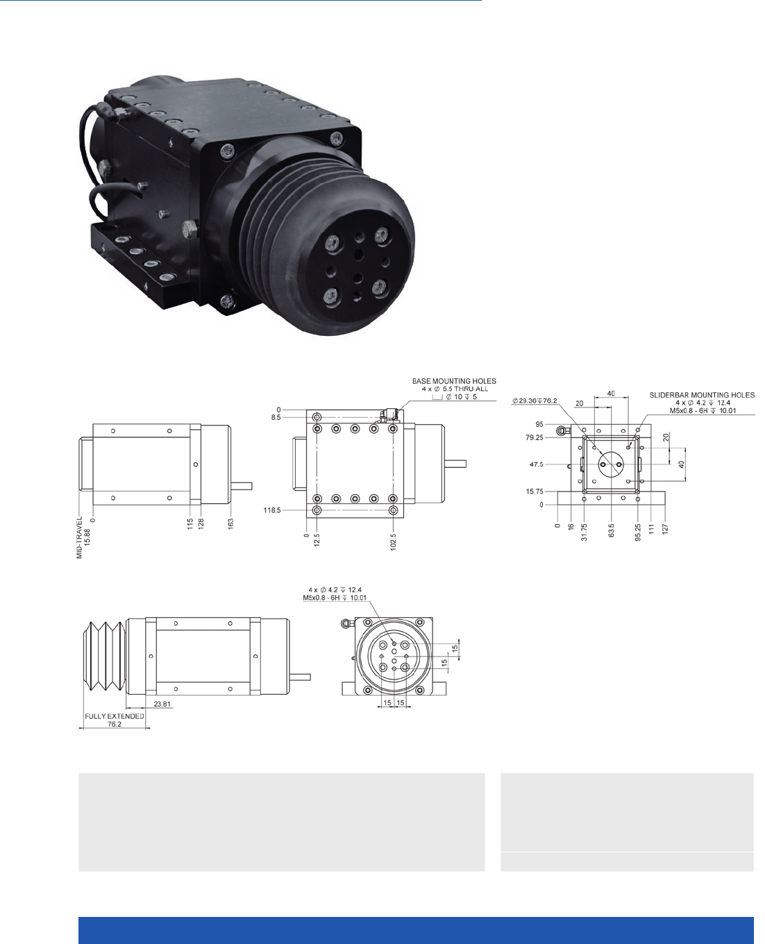
WWW.PI.WS
124
High-Performance Miniature Nanopositioning System
A-131 PIglide VC Voice Coil
Linear Stage with Air Bearings
n Ideal for scanning applications
or high-precision positioning
n Cleanroom compatible
n Travel ranges to 25 mm
n Load capacity to 100 N
n Acceleration to 80 m/s²
n Best flatness / straightness
>> Air bearings
>> Linear encoder
>> Voice Coil Drives
Technology Glossary ...................... page 290
Applications
n Medical Industry
n Scanning
n Machine Tool / Fast Tool
A-131.025xx, dimensions in mm
A-131.025xxB, dimensions in mm

MOTION | POSITIONING
125
A-131 Unit Tolerance
Motion
Active axes X
Travel range 25 mm
Pitch (1) 10 µrad max.
Yaw (1) 10 µrad max.
Straightness / flatness (1) ±0.125 µm max.
Velocity, unloaded (2) 1 m/s max.
Acceleration, unloaded (2) 80 m/s² max.
Mechanical properties
Load capacity in z (3) 100 N max.
Moved mass 0.85 kg
Overall mass 3.6 kg
Guide type Air bearing
Drive properties
Drive type Brushless voice coil drive, ironless, 1 phase
Intermediate circuit voltage,
effective
48, nominal
80, max.
V DC
Peak force 70.4 N typ.
Nominal force 22.3 N typ.
Force constant, effective 6.9 N/A typ.
Resistance 2.7 Ω typ.
Inductivity (at 1000 Hz) 1.4 mH typ.
Back EMF 6.9 V·s/m
Nominal power 28 W max.
Cabling Internal, no moving cable
A-131.025A1x A-131.025D1x A-131.025F1x
Positioning
Integrated sensor Incremental linear encoder Incremental linear encoder Incremental linear encoder
Sensor signal Sin/cos, 1 V peak-peak,
20 µm signal period
A/B quadrature, TTL A/B quadrature, TTL
Sensor resolution 1.2 nm (4) 100 nm (5) 500 nm (5)
Bidirectional repeatability ±0.1 µm (4) ±0.1 µm ±0.1 µm
Accuracy (6) 0.2 µm 0.2 µm 0.2 µm
Reference point switch Home index Home index Home index
Reference point switch repeatability ±1 encoder step ±1 encoder step ±1 encoder step
A-131
Miscellaneous
Operating pressure (7) 75 to 85 psi (520 to 585 kPa)
Air consumption <1.0 SCFM (28 SLPM)
Air quality Clean (filtered to 1.0 µm or better) – ISO 8573-1 Class 1
Oil free – ISO 857-1 Class 1
Dry (–15 °C dew point) – ISO 8573-1 Class 3
Materials Hardcoat aluminum, stainless steel fasteners
(1) Dependent on the flatness of the surface, on which the stage is mounted.
(2) Can be limited by the payload, controller or drive.
(3) Assumes that the center of gravity is centered no more than 50 mm from the motion platform.
(4) Assumes 16384x interpolation. Contact PI for the use of other factors.
(5) Alternative resolutions on request. Higher resolutions can limit the velocity.
(6) Improved accuracy can be obtained with controller-based error compensation. The stage must be ordered with a controller from PI to reach these values.
(7) To protect the stage against damage, it is recommended to connect an air pressure sensor to the Motion-Stop input of the controller.
Translation Stages
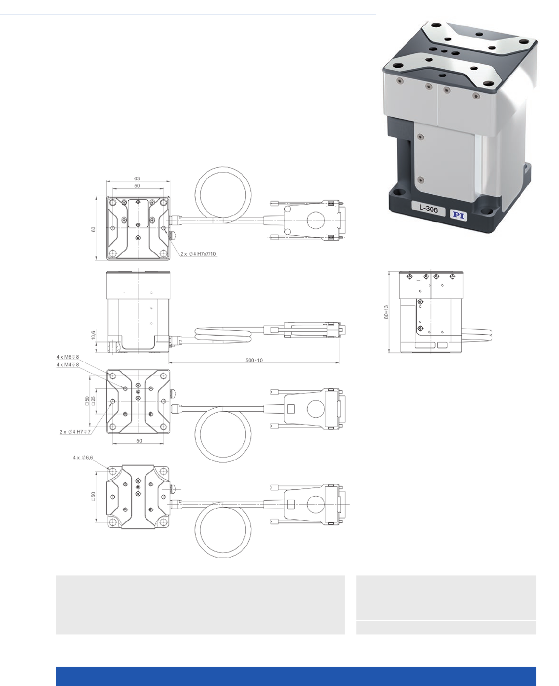
WWW.PI.WS
126
Compact Design, Multi-Axis Combinations
L-306 Compact Precision Z Stage
>> Linear Encoder
Technology Glossary ...................... page 290
Applications
n General Automation
n Photonics
n Scientific Instrumentation
n Semiconductor
n Compact design: Surface 63 mm × 63 mm
n Stepper motors and closed-loop DC motors
n Optional linear encoder for direct position measurement
n Crossed roller guides, anti-creep
n Noncontact reference and limit switches
L-306, dimensions in mm

MOTION | POSITIONING
127
L-306.011100 L-306.011112 L-306.013112 Unit Tolerance
Z stage with 2-phase
stepper motor
Z stage with 2-phase
stepper motor, linear
encoder with A/B
quadrature signal
transmission
Z stage with DC motor,
linear encoder with
A/B quadrature signal
transmission
Motion and positioning
Travel range 13 13 13 mm
Integrated sensor – Incremental linear
encoder
Incremental linear
encoder
Sensor resolution – 5 50 nm
Design resolution 2.5 0.005 0.05 µm
Minimum
incremental motion
2.5 0.1 0.1 µm typ.
Unidirectional
repeatability
0.5 0.1 0.1 µm typ.
Bidirectional
repeatability
±2 ±0.5 ±0.5 µm typ.
Pitch ±175 ±175 ±175 µrad typ.
Yaw ±150 ±150 ±150 µrad typ.
Straightness / flatness ±3 ±3 ±3 µm typ.
Velocity 5 5 5 mm/s max.
Reference and limit
switches
Optical Optical Optical
Mechanical properties
Guide type Crossed roller guide
with anti-creep system
Crossed roller guide
with anti-creep system
Crossed roller guide
with anti-creep system
Drive screw type Ball screw Ball screw Ball screw
Drive screw pitch 0.5 0.5 0.5 mm
Push/pull force 20 20 20 N max.
Holding force, power off 20 20 20 N typ.
Permissible lateral force 10 10 10 N max.
Load capacity 20 20 20 N max.
Permissible torque in
θX, θY
1 1 1 N·m max.
Permissible torque in θZ2 2 2 N·m max.
Drive properties
Motor type 2-phase stepper motor 2-phase stepper motor DC motor
Miscellaneous
Operating temperature
range
5 to 40 5 to 40 5 to 40 °C
Humidity 20 – 80 % rel.,
not condensing
20 – 80 % rel.,
not condensing
20 – 80 % rel.,
not condensing
Material Anodized aluminum,
steel
Anodized aluminum,
steel
Anodized aluminum,
steel
Mass 0.6 0.6 0.6 kg ±5 %
Moved mass 0.18 0.18 0.18 kg ±5 %
Connection HD Sub-D 26 (m) (motor) HD Sub-D 26 (m)
(motor and encoder)
HD Sub-D 26 (m)
(motor and encoder)
Cable length 0.5 0.5 0.5 m
Recommended
controllers
C-663.12 (single axis)
SMC Hydra (double axis)
C-885 with C-663.12C885
(up to 20 axes)
ACS modular controller
C-663.12 (single axis)
SMC Hydra (double axis)
C-885 with C-663.12C885
(up to 20 axes)
ACS modular controller
C-863 (single axis)
C-884 (up to 6 axes)
C-885 with C-863.20C885
(to 40 axes)
ACS modular controller
All cables required for operation with the ordered controller are included in the scope of delivery.
The cable length is 3 m. Cable for connecting to other controllers can be ordered as accessory.
Ask about custom designs!
Translation Stages
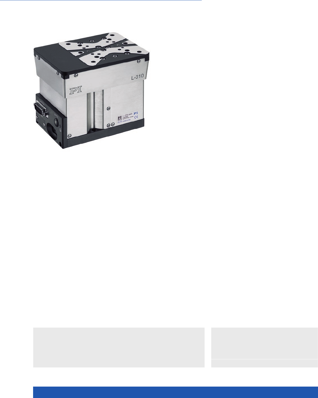
WWW.PI.WS
128
Compact Multi-Axis Combinations with Linear and Rotation Stages
L-310 Precision Z Stage
>> ActiveDrive
>> Linear Encoder
>> Vacuum-Compatible Versions
Technology Glossary ...................... page 290
Applications
n General Automation
n Photonics
n Scientific Instrumentation
n Semiconductor
n Travel range 26 mm (1”)
n High-resolution encoder
n ActiveDrive DC, DC, BLDC,
and stepper motors
n Zero-play ball screw
n MTBF 10000 h
n Self-locking to 10 kg
Precision-class Z stage
High guiding accuracy and stiffness due to ball screws and crossed roller
guides. Stress-relieved aluminum base for highest stability. Vacuum versions
available on request. Noncontact limit and reference point switches (Hall effect).
Reference point switch with direction sensing in the middle of the travel range.
Highly accurate position measuring with incremental linear encoder
Noncontact optical linear encoders measure the actual position directly at the
motion platform with the greatest accuracy so that nonlinearity, mechanical
play or elastic deformation have no influence on position measuring.
Minimum incremental motion and slow motion
In conjunction with the SMC Hydra controller, versions with stepper motor and
integrated linear encoder (L-310.xASD) achieve repeatable minimum incremental
motion in the range of the sensor resolution. The same configuration attains
constant low velocities of a few sensor increments per second.
Drive types
n .xxSD variant: 2-phase stepper motor for
high torque even at low velocities and high
resolution.
n .xxAD variant: ActiveDrive DC motor for high
velocity: Control via pulse-width-modulated
(PWM) signals, the operating voltage is
attained via an amplifier integrated in the
motor housing.
n .023xxx variant: DC servo motor
n .025xxx variant: Brushless DC motor (BLDC)
for high rotational velocity. Smooth running
and low wear, therefore higher lifetime.
Position measurement
n Versions with DC motor: Rotary encoder
n Optional: Integrated linear encoder,
installed centrically.

MOTION | POSITIONING
129
L-310 Unit Tolerance
Motion
Active axis Z
Travel range 26 mm
Pitch / yaw ±150 µrad typ.
Straightness / flatness ±3 µm typ.
Velocity L-310.2xAD: 20
L-310.2xSD: 15
L-310.02xxxx: 50
mm/s max.
L-310 Unit Tolerance
Mechanical properties
Drive screw Ball screw
Drive screw pitch 1 mm
Guide Crossed roller guide with anti-creep system
Holding force, power off L-310.2xAD: 30 / L-310.2xSD: 50 / L-310.02xxxx: 30 N max.
Permissible
lateral force, Fx
100 N max.
Permissible
lateral force, Fy
50 N max.
Permissible
torque in θX (Mx)
40 N·m max.
Permissible
torque in θY (My)
80 N·m max.
Permissible
torque in θZ (Mz)
80 N·m max.
L-310.2ASD
L-310.023211
L-310.24AD
L-310.xxx212
L-310.20AD
L-310.xxx232
L-310.20SD Unit Tolerance
Positioning
Design resolution 0.005 0.05 L-310.20AD: 0.061
L-310.023232: 0.061
L-310.025232: 0.05
5 µm
Integrated sensor Incremental
linear encoder
Incremental
linear encoder
L-310.025212
additional
rotary encoder
Rotary encoder –
Sensor signal Sin/cos,
1 V peak-peak,
20 µm signal
period
A/B quadrature,
TTL
A/B quadrature,
TTL
–
Sensor resolution
rotary encoder
– L-310.025212:
20000
L-310.20AD: 16384
L-310.023232:
16384
L-310.025232:
20000
– Cts./rev.
Sensor resolution
linear encoder
0.05 – µm
Minimum incremental
motion
L-310.2ASD: 0.05
L-310.023211: 0.2
L-310.24AD: 0.3
L-310.xxx212: 0.2
0.3 0.3 µm typ.
Unidirectional
repeatability
L-310.2ASD: 0.1
L-310.023211: 0.2
L-310.24AD: 0.3
L-310.xxx212: 0.2
0.3 0.3 µm typ.
Bidirectional
repeatability
±0.2 ±0.2 ±2 ±2 µm typ.
Limit switches Hall effect Hall effect Hall effect Hall effect
Reference point switch
repeatability
2 2 2 2 µm typ.
Translation Stages
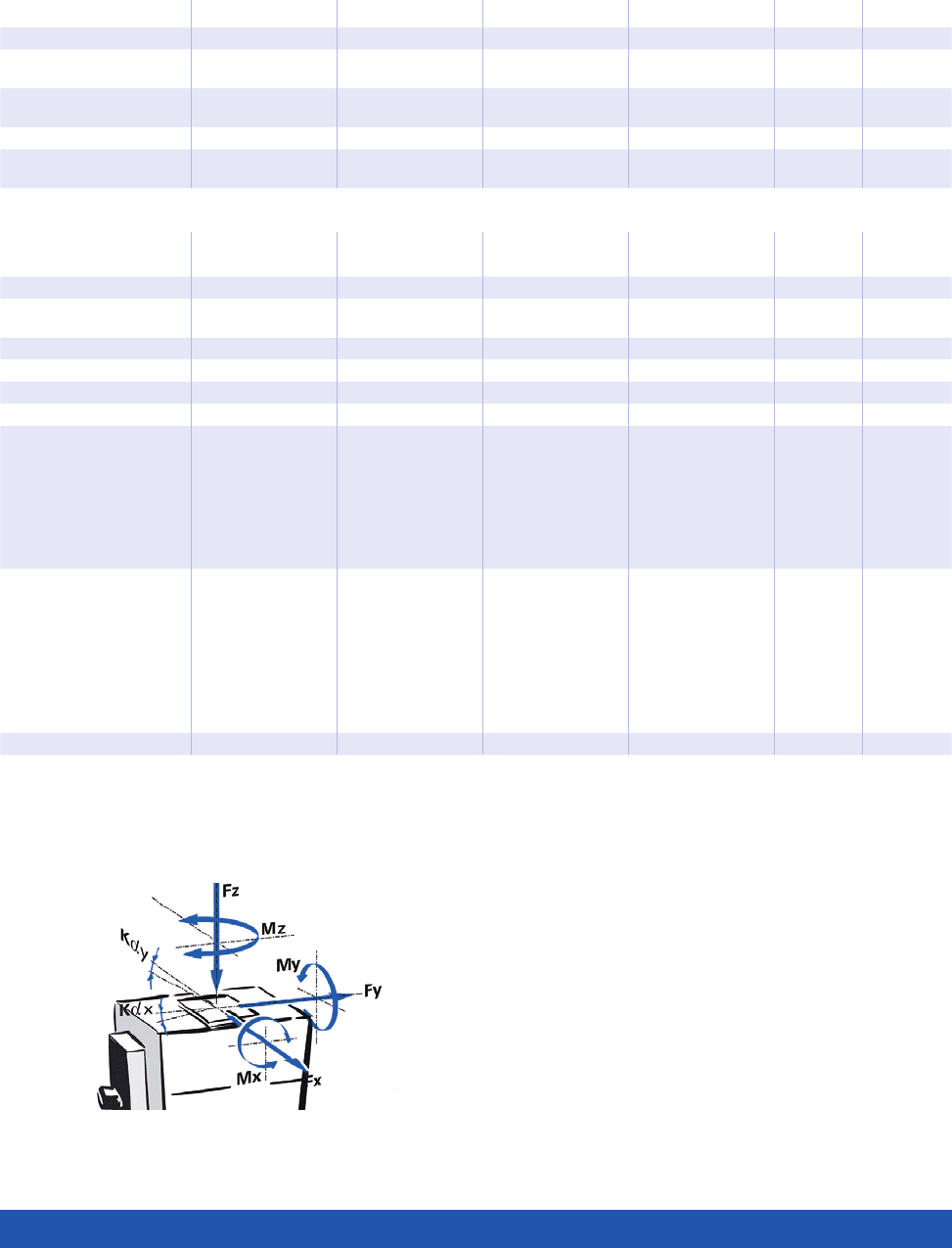
WWW.PI.WS
130
L-310.xxSD L-310.xxAD L-310.xx3xxx L-310.xx5xxx Unit Tolerance
Drive properties
Motor type 2-phase stepper
motor
DC motor with
PWM control
DC motor BLDC motor
Operating voltage,
nominal
24 24 24 24 V nom.
Operating voltage, max. 48 48 48 48 V max.
Step resolution 200 – – – Full
steps/rev.
All cables required for operation with the ordered controller are included in the scope of delivery. The cable length is 3 m.
Cable for connecting to other controllers can be ordered as accessory.
Ask about custom designs!
L-310.20SD L-310.2ASD L-310.023xxx
L-310.2xAD
L-310.025xxx Unit Tolerance
Miscellaneous
Operating temperature
range
5 to 40 5 to 40 5 to 40 5 to 40 °C
Material Al (black anodized) Al (black anodized) Al (black anodized) Al (black anodized)
MTBF – – – 10000 h
Mass 2.7 2.8 2.7 2.7 kg ±5 %
Moved mass, unloaded 0.9 0.9 0.9 0.9 kg ±5 %
Connection HD Sub-D 26 (m) HD Sub-D 26 (m)
(motor) Sub-D 9
(m) (sensor)
L-310.2xAD:
Sub-D 15 (m)
L-310.023232:
HD Sub-D 26 (m)
L-310.023211:
HD Sub-D 26 (m)
(motor), Sub-D 9
(m) (sensor)
HD Sub-D 26 (m)
Recommended
controllers / drivers
C-663.12
(single axis)
SMC Hydra
(double axis)
C-885 with
C-663.12C885
(up to 20 axes)
ACS modular
controller
C-663.12
(single axis)
SMC Hydra
(double axis)
C-885 with
C-663.12C885
(up to 20 axes
ACS modular
controller
C-863
(single axis)
C-884
(up to 6 axes)
C-885 with
C-863.20C885
(to 40 axes)
ACS modular
controller
C-891
(single axis)
C-885 with
C-891.10C885
(up to 20 axes)
ACS modular
controller
Direction of the
axes and torques
for Z stages
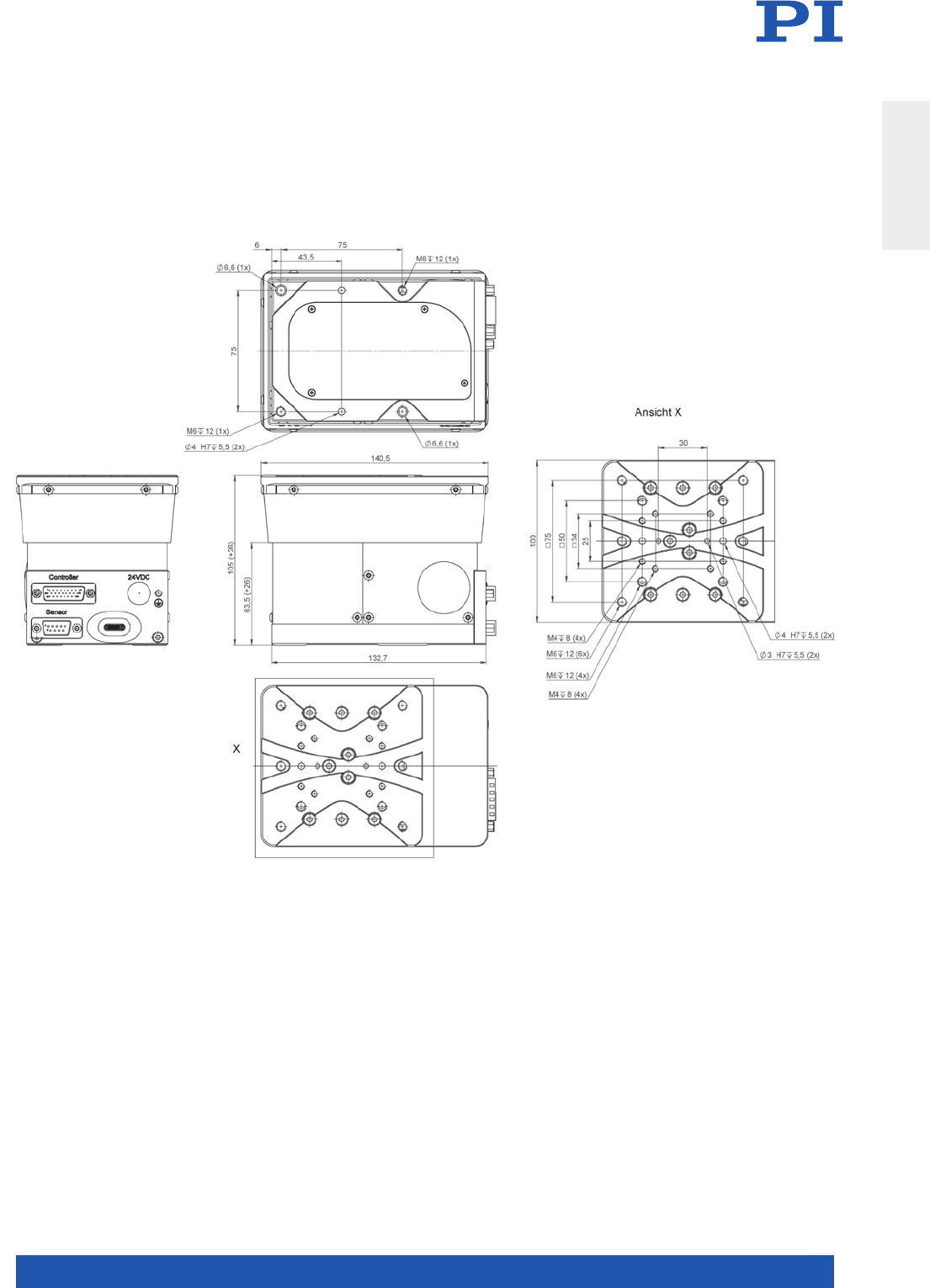
MOTION | POSITIONING
131
L-310, dimensions in mm
Translation Stages
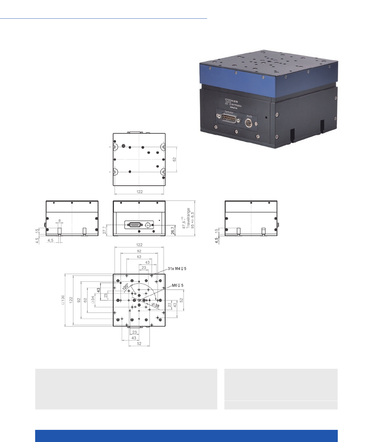
WWW.PI.WS
132
Compact XYZ Combinations with M-511 Translation Stage Series
M-501 Precision Z Stage
n Extremely high-resolution encoder
n ActiveDrive motor
n Zero-play ball screws
n Noncontact limit and reference point switches
n Stress-relieved aluminum base for highest stability
n Self-locking to 10 kg
M-501, dimensions in mm
>> ActiveDrive
>> Incremental Encoder
Technology Glossary ...................... page 290
Applications
n General Automation
n Photonics
n Scientific Instrumentation
n Semiconductor

MOTION | POSITIONING
133
M-501.1PD M-501.1DG Unit Tolerance
Active axes Z Z
Motion and positioning
Travel range 12.5 12.5 mm
Integrated sensor Rotary encoder Rotary encoder
Sensor resolution 40960 2048 Cts./rev.
Design resolution 0.024 0.005 µm
Minimum incremental motion <0.1 <0.1 µm
Unidirectional repeatability 0.1 0.1 µm
Pitch ±150 ±150 µrad
Yaw ±150 ±150 µrad
Velocity 3 1 mm/s max.
Reference point switch
repeatability
1 1 µm
Mechanical properties
Drive screw pitch 1 1 mm
Gear ratio 80/26 (belt drive) 80/26 (belt drive);
(28/12)4:1 ~ 29.6:1 gearhead
Load capacity 50 100 N max.
Holding force 20 100 N max.
Drive properties
Motor type DC motor with PWM control
(ActiveDrive)
DC gear motor
Operating voltage 24 0 to ±12 V
Motor power 17 4 W
Reference and limit switches Hall effect Hall effect
Miscellaneous
Operating temperature range 10 to 50 –20 to 50 °C
Material Al (black anodized) Al (black anodized)
Mass 2.6 2.6 kg ±5 %
Recommended controllers /
drivers
C-863 (single axis)
C-884 (up to 6 axes)
C-863 (single axis)
C-884 (up to 6 axes)
Ask about custom designs!
Translation Stages
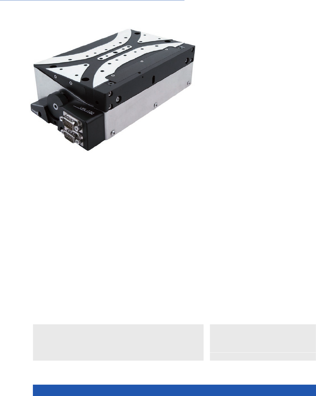
WWW.PI.WS
134
Excellent Accuracy for High Loads
UPL-120 Precision Z Stage
n Travel range 13 mm (1/2”)
n Unidirectional repeatability to 0.05 µm
n Load capacity to 20 kg
n Integrated optical limit switches
n Available with direct-measuring encoder
n Crossed roller guide, anti-creep
>> Linear Encoder
Technology Glossary ...................... page 290
Applications
n General Automation
n Photonics
n Scientific Instrumentation
n Semiconductor
Reference-class Z stage
Extremely accurate and reliable positioning. Crossed roller guides for smooth
feed at high loads. Stress-relieved aluminum base for highest stability. Drive
variants with DC motor and 2-phase stepper motor. Noncontact limit switches.
Highly accurate position measuring with incremental linear encoder
Noncontact optical linear encoders measure the actual position directly at the
motion platform with the greatest accuracy so that nonlinearity, mechanical
play or elastic deformation have no influence on position measuring.
Crossed roller guide
With crossed roller guides, the point contact of the balls in ball guides is
replaced by line contact of the hardened rollers. Consequently, they are consi-
derably stiffer and need less preload, which reduces friction and allows smoo-
ther running. Crossed roller guides are also distinguished by high guiding accu-
racy and load capacity. Force-guided rolling element cages prevent cage creep.

MOTION | POSITIONING
135
6635911030 6635921030 6635911130 6635921130-0001 Unit Tolerance
Z stage with
DC motor and
rotary encoder
Z stage with
stepper motor
Z stage with
DC motor,
linear and
rotary encoder
Z stage with
stepper motor
and linear
encoder
Active axes Z Z Z Z
Motion and positioning
Travel range 13 13 13 13 mm
Integrated sensor Rotary encoder – Linear encoder
Rotary encoder
Linear encoder
Sensor signal rotary
encoder
A/B quadrature,
RS-422
– A/B quadrature,
RS-422
–
Sensor signal linear
encoder
– – A/B quadrature,
RS-422
Sin/cos,
1 V peak-peak,
20 µm signal
period
Design resolution 0.013 1.34 0.05 0.005 µm
Sensor resolution
rotary encoder
20000 –20000 – Cts./rev.
Sensor resolution
linear encoder
– – 0.05 – µm
Minimum incremental
motion
0.1 0.1 0.1 0.05 µm typ.
Unidirectional
repeatability
0.1 0.1 0.1 0.05 µm typ.
Bidirectional
repeatability
±2 ±2 ±0.1 ±0.05 µm typ.
Pitch ±100 ±100 ±100 ±100 µrad typ.
Yaw ±100 ±100 ±100 ±100 µrad typ.
Straightness ±3.0 ±3.0 ±3.0 ±3.0 µm typ.
Flatness ±3.0 ±3.0 ±3.0 ±3.0 µm typ.
Velocity 6 3 6 3 mm/s max.
Reference point switch
repeatability
<1 <1 <1 <1 µm typ.
Mechanical properties
Guide type Crossed roller
guide with anti-
creep system
Crossed roller
guide with anti-
creep system
Crossed roller
guide with anti-
creep system
Crossed roller
guide with anti-
creep system
Drive screw type Ball screw Ball screw Ball screw Ball screw
Drive screw pitch 1 1 1 1 mm
Gear ratio 2911:780 2911:780 2911:780 2911:780
Push/pull force,
power on
200 200 200 200 N max.
Holding force, power off 40 80 40 80 N typ.
Load capacity 200 200 200 200 N max.
Permissible lateral force
Fy in Y
150 150 150 150 N max.
Permissible torque Mx
in θx
130 130 130 130 N·m max.
Permissible torque My
in θy
38 38 38 38 N·m max.
Permissible torque Mz
in θZ
150 150 150 150 N·m max.
Translation Stages
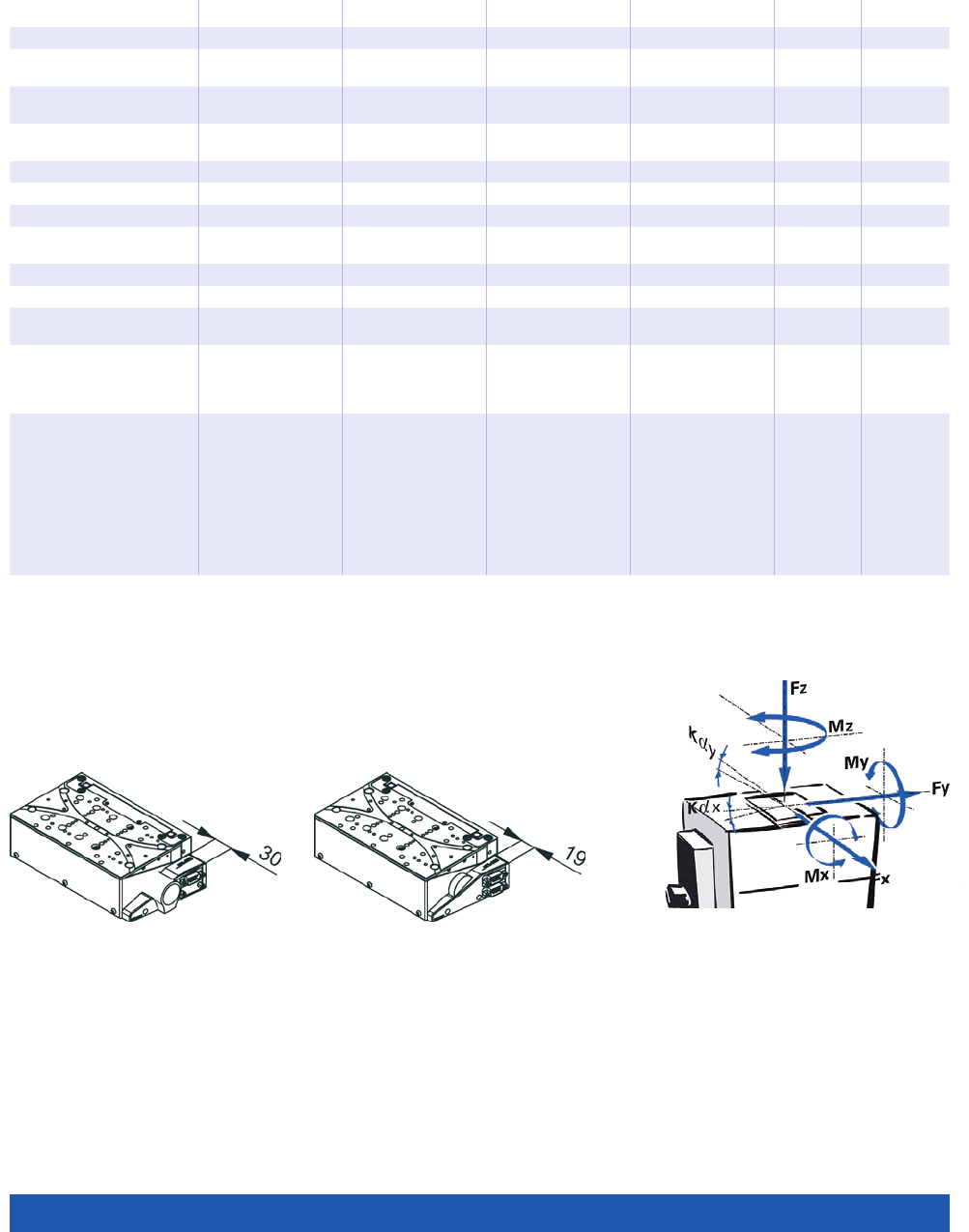
WWW.PI.WS
136
UPL-120, DC motor,
dimensions in mm
UPL-120, stepper motor,
dimensions in mm
Direction of the
axes and torques
for Z stages
6635911030 6635921030 6635911130 6635921130-0001 Unit Tolerance
Drive properties
Motor type DC motor 2-phase
stepper motor
DC motor 2-phase
stepper motor
Step resolution – 200 – 200 Full steps/
rev.
Operating voltage,
nominal
24 24 24 24 V nom.
Operating voltage, max. 48 48 48 48 V max.
Limit switches Optical Optical Optical Optical
Miscellaneous
Operating temperature
range
5 to 40 5 to 40 5 to 40 5 to 40 °C
Mass 2.4 2.3 2.4 2.4 kg ±5 %
Moved mass 1.3 1.3 1.3 1.3 kg ±5 %
Material Aluminum,
black anodized
Aluminum,
black anodized
Aluminum,
black anodized
Aluminum,
black anodized
Connection HD Sub-D 15 (m) HD Sub-D 15 (m) Motor:
HD Sub-D 15 (m)
Sensor:
Sub-D 9 (m)
Motor:
HD Sub-D 15 (m)
Sensor:
Sub-D 9 (m)
Recommended
controllers / drivers
C-863
(single axis)
C-884
(up to 6 axes)
C-885 with
C-863.20C885
(to 40 axes)
ACS modular
controller
C-663.12
(single axis)
SMC Hydra
(double axis)
C-885 with
C-663.12C885
(up to 20 axes)
ACS modular
controller
C-863
(single axis)
C-884
(up to 6 axes)
C-885 with
C-863.20C885
(to 40 axes)
ACS modular
controller
C-663.12
(single axis)
SMC Hydra
(double axis)
C-885 with
C-663.12C885
(up to 20 axes)
ACS modular
controller
Connecting cables for motor and sensor are not in the scope of delivery and must be ordered separately.
Ask about custom designs!
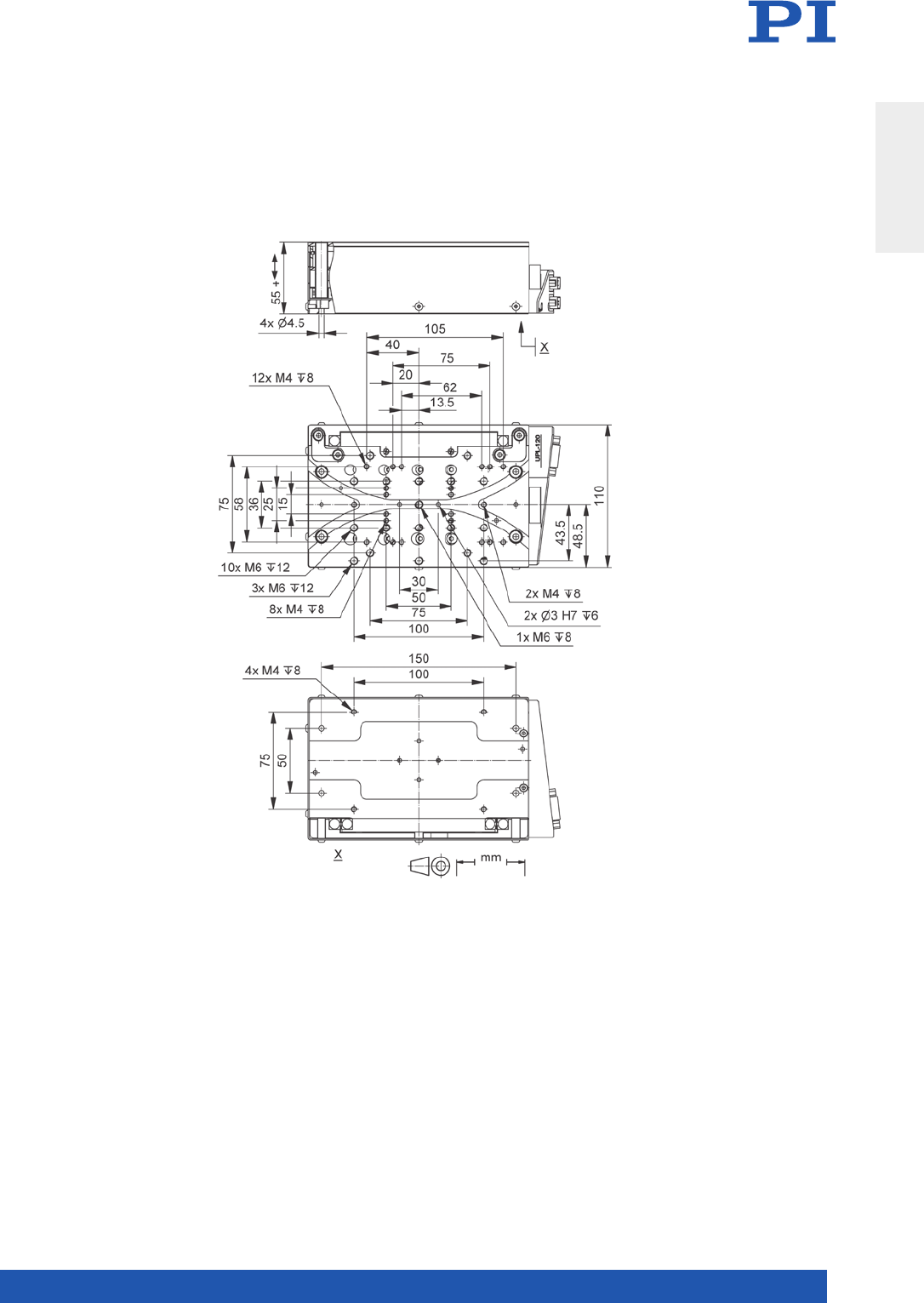
MOTION | POSITIONING
137
UPL-120, dimensions in mm
Translation Stages
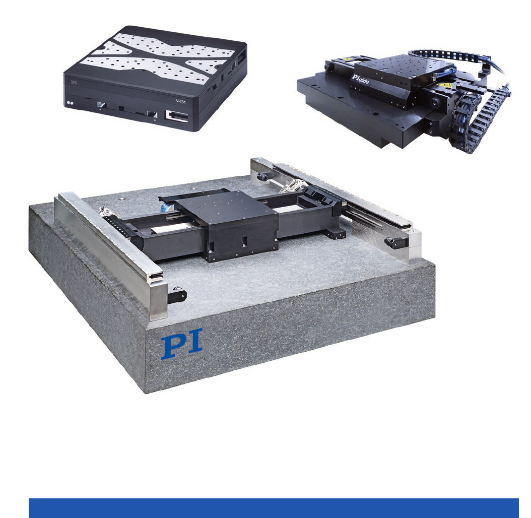
WWW.PI.WS
138
XY Stages

MOTION | POSITIONING
139
XY Stages with Mechanical Bearings ...................................................................................................................................... 140
L-731 Precision XY Stage .............................................................................................. 140
V-731 PIMag® High-Precision XY Stage ......................................................................... 144
L-741 Precision XY Stage .............................................................................................. 146
V-741 PIMag® High-Precision XY Stage ......................................................................... 150
L-738 Precision XY Stage .............................................................................................. 152
V-738 PIMag® High-Precision XY Stage ......................................................................... 156
PIglide XY Stages with Air Bearings ....................................................................................................................................... 158
A-311 PIglide IS Planar Scanner with Air Bearing .......................................................... 158
A-322 PIglide HS Planar Scanner with Air Bearing ........................................................ 160
XY Stages
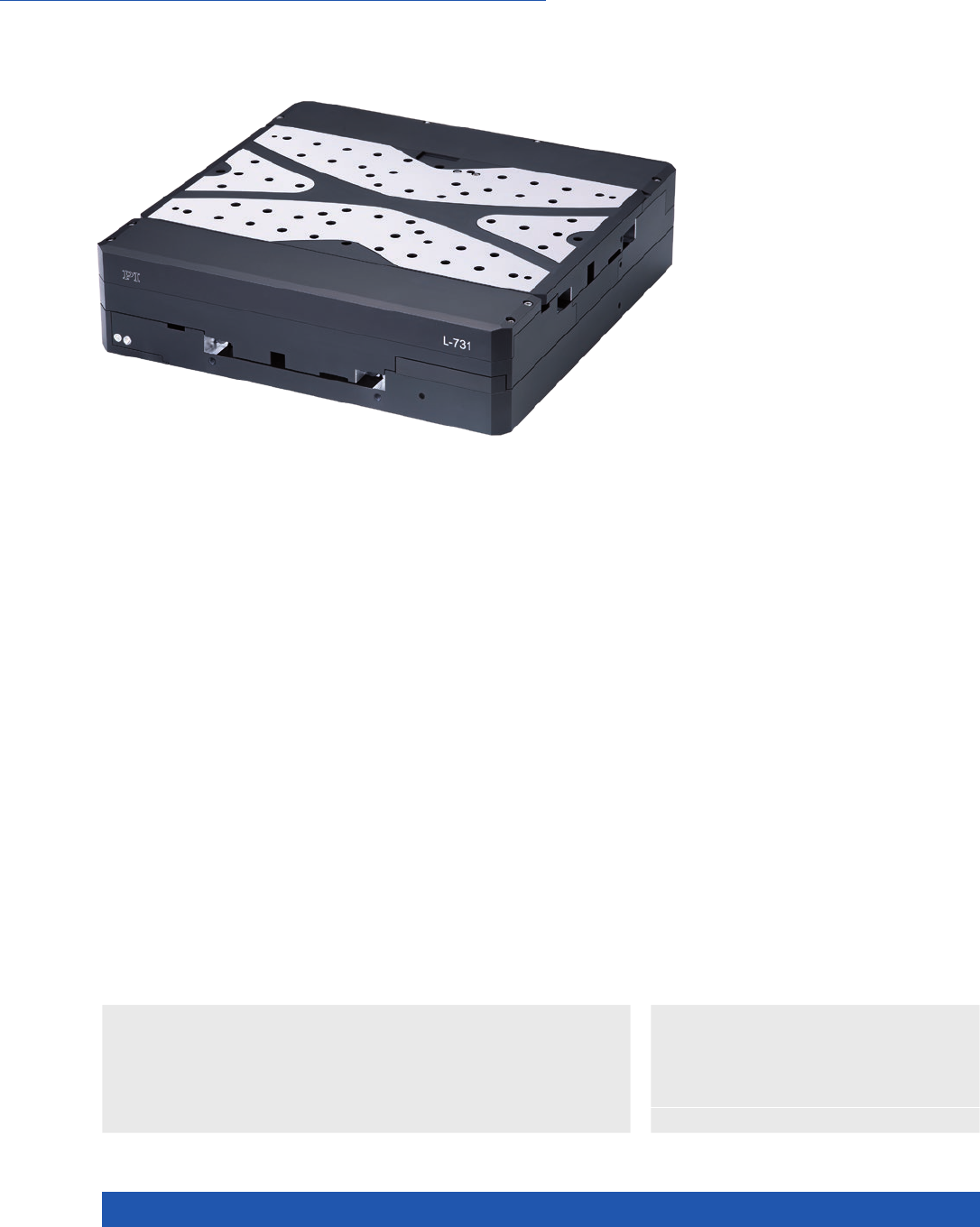
WWW.PI.WS
140
High Travel Accuracy and Stability
L-731 Precision XY Stage
n Travel range 205 mm × 205 mm (8”)
n Unidirectional repeatability to 0.05 µm
n Velocity to 90 mm/s
n 2-phase stepper motor or DC motors
n Incremental encoder with 1 nm resolution
n Rotary encoder with 20000 impulses/
revolution
n Crossed roller guide, anti-creep
>> Incremental Encoder
Technology Glossary ...................... page 290
Drive types
n 2-phase stepper motor for high torque even
at low velocities and higher resolution
n DC motor for high velocity constancy, low
vibration, and high velocities
Other travel ranges on request.
Highly accurate position measuring with incremental linear encoder
Noncontact optical linear encoders measure the actual position directly at the
motion platform with the greatest accuracy so that nonlinearity, mechanical
play or elastic deformation have no influence on position measuring.
Optical limit and reference point switches.
Crossed roller guide
With crossed roller guides, the point contact of the balls in ball guides
is replaced by line contact of the hardened rollers. Consequently, they are
considerably stiffer and need less preload, which reduces friction and allows
smoother running. Crossed roller guides are also distinguished by high guiding
accuracy and load capacity. Force-guided rolling element cages prevent cage
creep.
Applications
n Biotechnology
n Laser Cutting
n Laser Marking
n Medical Industry
n Metrology / Testing

MOTION | POSITIONING
141
Stages with DC motor L-731.093111 / L-731.093112 / L-731.093132 Unit Tolerance
Motion
Active axes X, Y
Travel range 205 × 205 mm
Angular error xry (pitch) ±50 µrad typ.
Angular error xrz (yaw) ±30 µrad typ.
Angular error yrx (pitch) ±40 µrad typ.
Angular error yrz (yaw) ±30 µrad typ.
Straightness / flatness ±2 µm typ.
Orthogonality ±96.963 µrad typ.
Velocity L-731.093111 / L-731.093112: 50
L-731.093132: 90
mm/s max.
Stages with DC motor L-731.093xxx Unit Tolerance
Mechanical properties
Drive screw type Ball screw
Drive screw pitch 2 mm
Guide type Crossed roller guide with anti-creep system
Load capacity 200 N max.
Permissible torque Mx in θX125 N·m max.
Permissible torque My in θY125 N·m max.
Permissible torque Mz in θZ125 N·m max.
Drive properties
Motor type DC motor
Operating voltage, nominal 24 V nom.
Operating voltage, max. 48 V max.
Stages with DC motor L-731.093111 L-731.093112 L-731.093132 Unit Tolerance
Positioning
Integrated sensor Incremental linear
encoder
Incremental linear
encoder
Incremental rotary
encoder
Sensor signal Sin/cos, 1 V peak-
peak, 20 µm signal
period
A/B quadrature,
TTL
A/B quadrature,
TTL
Design resolution 0.001 0.01 0.1 µm
Sensor resolution rotary encoder – – 20000 Cts./rev.
Minimum incremental motion 0.1 0.5 0.8 µm typ.
Unidirectional repeatability 0.1 0.5 0.8 µm typ.
Bidirectional repeatability ±0.5 ±0.5 ±2.5 µm typ.
Reference point switch repeatability <1 <1 <1 µm typ.
Reference and limit switches Optical Optical Optical
XY Stages

WWW.PI.WS
142
Stages with stepper motor L-731.40SD / L-731.44SD / L-731.4ASD Unit Tolerance
Motion
Active axes X, Y
Travel range 205 × 205 mm
Angular error xry (pitch) ±50 µrad typ.
Angular error xrz (yaw) ±30 µrad typ.
Angular error yrx (pitch) ±40 µrad typ.
Angular error yrz (yaw) ±30 µrad typ.
Straightness / flatness ±2 µm typ.
Orthogonality ±96.963 µrad typ.
Velocity 45 mm/s max.
Stages with stepper motor L- 7 3 1. 4 x S D Unit Tolerance
Mechanical properties
Drive screw type Ball screw
Drive screw pitch 2 mm
Guide type Crossed roller guide with anti-creep system
Load capacity 200 N max.
Permissible torque Mx in θX125 N·m max.
Permissible torque My in θY125 N·m max.
Permissible torque Mz in θZ125 N·m max.
Drive properties
Motor type Stepper motor, 2-phase
Operating voltage, nominal 24 V nom.
Operating voltage, max. 48 V max.
Stepper motor 200 Full steps/
rev.
Stages with stepper motor L- 7 3 1. 4 0 S D L- 7 3 1 . 4 4 S D L- 7 3 1 . 4 A S D Unit Tolerance
Positioning
Integrated sensor – Incremental linear
encoder
Incremental linear
encoder
Sensor signal – A/B quadrature,
TTL
Sin/cos, 1 V
peak-peak, 20 µm
signal period
Design resolution 10.0 0.01 0.001 µm
Minimum incremental motion 1 0.05 0.05 µm typ.
Unidirectional repeatability 1 0.05 0.05 µm typ.
Bidirectional repeatability ±2.5 ±0.5 ±0.5 µm typ.
Reference and limit switches Optical Optical Optical
Stages with DC motor L-731.093111 L-731.093112 / L-731.093132 Unit Tolerance
Miscellaneous
Operating temperature range 5 to 40 5 to 40 °C
Material Aluminum, black anodized Aluminum, black anodized
Mass 16 16 kg ±5 %
Moved mass in X, unloaded 12 12 kg ±5 %
Moved mass in Y, unloaded 3.5 3.5 kg ±5 %
Connection 2 × HD Sub-D 26 (m) (motor)
2 × Sub-D 15 (f) (sensor)
2 × HD Sub-D 26 (m)
(motor/sensor)
Recommended controllers / drivers SMC Hydra (double axis)
C-891 (single axis)
C-885 with C-891.10C885
(up to 20 axes)
ACS modular controller
C-863 (single axis)
C-884 (up to 6 axes)
C-885 with C-863.20C885
(to 40 axes)
ACS modular controller
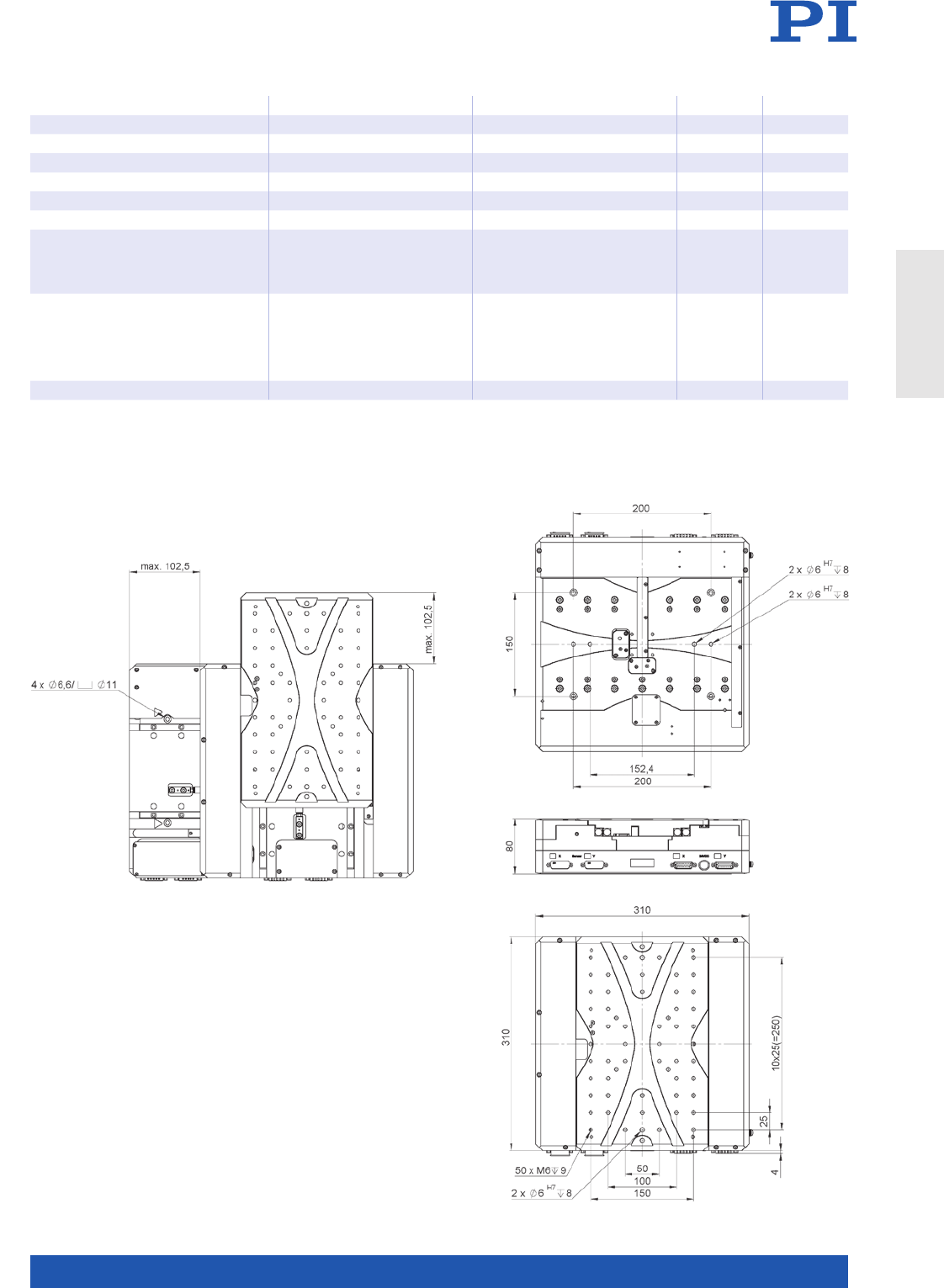
MOTION | POSITIONING
143
All cables required for operation with the ordered controller are included in the scope of delivery.
The cable length is 3 m. Cable for connecting to other controllers can be ordered as accessory.
Ask about custom designs!
Stages with stepper motor L-731.40SD / L-731.44SD L- 7 3 1 . 4 A S D Unit Tolerance
Miscellaneous
Operating temperature range 5 to 40 5 to 40 °C
Material Aluminum, black anodized Aluminum, black anodized
Mass 15.5 15.5 kg ±5 %
Moved mass in X, unloaded 12 12 kg ±5 %
Moved mass in Y, unloaded 3.5 3.5 kg ±5 %
Connection L-731.40SD: 2 × HD Sub-D
26 (m) (motor)
L-731.44SD: 2 × HD Sub-D
26 (m) (motor/sensor)
2 × HD Sub-D 26 (m) (motor)
2 × Sub-D 15 (f) (sensor)
Recommended controllers / drivers C-663.12 (single axis)
SMC Hydra (double axis)
C-885 with C-663.12C885
(up to 20 axes)
ACS modular controller
SMC Hydra (double axis)
ACS modular controller
L-731, dimensions in mm
XY Stages
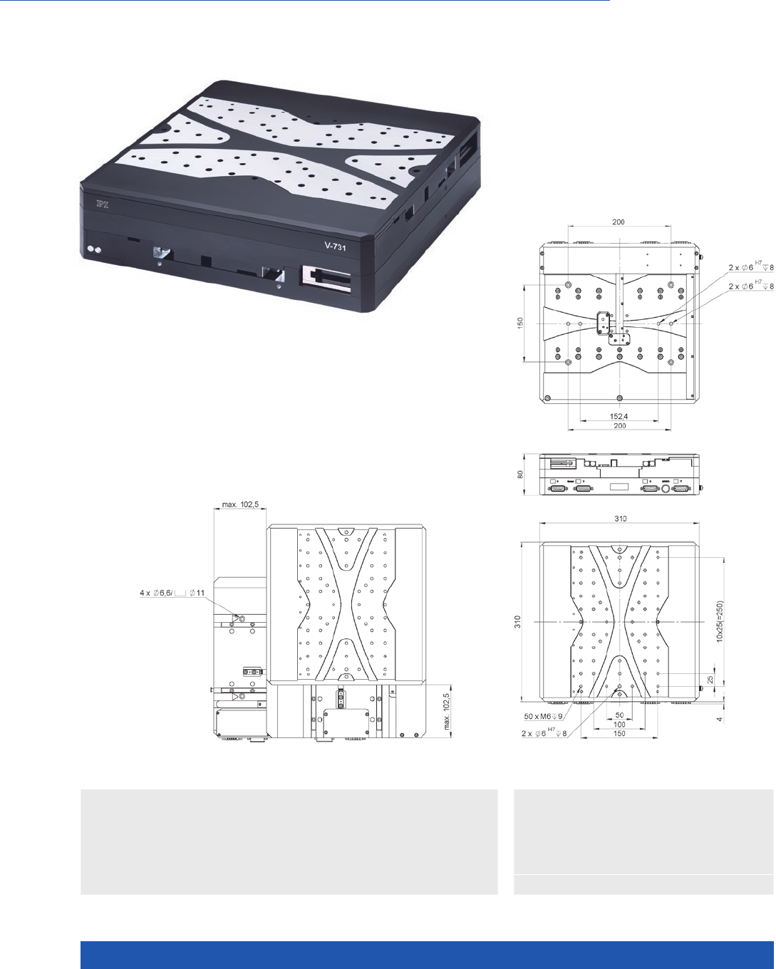
WWW.PI.WS
144
High Travel Accuracy and Stability, Magnetic Direct Drive
V-731 PIMag® High-Precision XY Stage
n Travel range 205 mm × 205 mm (8”)
n Unidirectional repeatability to 0.1 µm
n Ironless 3-phase linear motor
n Velocity to 200 mm/s
n Incremental linear encoder with 1 nm resolution
n Crossed roller guides, anti-creep
>> Incremental Encoder
>> PIMag® Magnetic Linear Motors
Technology Glossary ...................... page 290
V-731, dimensions in mm
Applications
n Automated Optical Inspection (AOI)
n Biotechnology
n Laser Cutting
n Laser Marking
n Medical Industry
n Metrology / Testing
n Scanning

MOTION | POSITIONING
145
V-731.096111 Unit Tolerance
Motion and positioning
Active axes X, Y
Travel range 205 × 205 mm
Integrated sensor Incremental linear encoder
Design resolution 0.001 µm
Sensor signal Sin/cos, 1 V peak-peak,
20 µm signal period
Minimum incremental motion 0.02 µm typ.
Unidirectional repeatability 0.1 µm typ.
Bidirectional repeatability ±0.25 µm typ.
Angular error xry (pitch) ±50 µrad typ.
Angular error xrz (yaw) ±30 µrad typ.
Angular error yrx (pitch) ±40 µrad typ.
Angular error yrz (yaw) ±30 µrad typ.
Orthogonality ±96.963 µrad typ.
Straightness / flatness ±2 µm typ.
Velocity 200 mm/s max.
Acceleration in X, without load 5 m/s² max.
Acceleration in Y, without load 15 m/s² max.
Reference and limit switches Optical
Mechanical properties
Load capacity 50 N max.
Permissible torque in θX, θY125 N·m max.
Permissible torque in θZ125 N·m max.
Guide Crossed roller guide with
anti-creep system
Drive properties
Motor type Ironless 3-phase linear motor
Operating voltage, nominal 48 V nom.
Operating voltage, max. 48 V max.
Peak force 80 N max.
Nominal force 29 N typ.
Peak current, effective 5 A typ.
Nominal current, effective 1. 5 A typ.
Force constant, effective 19.9 N/A typ.
Motor constant 4.89 N/√W typ.
Electrical time constant 0.4 ms
Resistance phase-phase 11 Ω typ.
Inductance phase-phase 3.6 mH typ.
Back EMF phase-phase 16 V·s/m max.
Pole pitch N-N 30 mm
Miscellaneous
Operating temperature range 5 to 40 °C
Material Aluminum, black anodized
Moved mass in X 15.4 kg ±5 %
Moved mass in Y 5.6 kg ±5 %
Overall mass 19.4 kg ±5 %
MTBF 20000 h
Connection 2 × HD Sub-D 26 (m) (motor)
2 × Sub-D 15 (f) (sensor)
Recommended controller SMC Hydra (double axis)
C-891 (single axis)
C-885 with C-891.10C885 (up to 20 axes)
ACS modular controller
All cables required for operation with the ordered controller are included in the scope of delivery.
The cable length is 3 m. Cable for connecting to other controllers can be ordered as accessory.
Ask about custom designs!
XY Stages
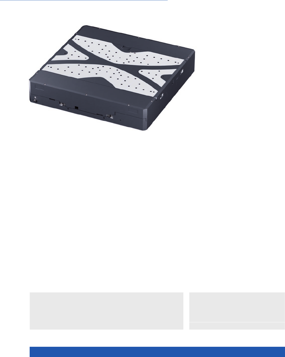
WWW.PI.WS
146
High Travel Accuracy and Stability, 305 × 305 mm Travel Range
L-741 Precision XY Stage
n Travel range 305 mm × 305 mm (12”)
n Unidirectional repeatability to 0.05 µm
n Velocity to 90 mm/s
n 2-phase stepper motors or DC motors
n Incremental linear encoder with 1 nm resolution
n Rotary encoder with 20000 impulses/revolution
n Crossed roller guide, anti-creep
>> Incremental Encoder
Technology Glossary ...................... page 290
Drive types
n 2-phase stepper motor for high torque even
at low velocities and higher resolution
n DC motor for high velocity constancy, low
vibration, and high velocities
Other travel ranges on request.
Highly accurate position measuring with incremental linear encoder
Noncontact optical linear encoders measure the actual position directly at
the motion platform with the greatest accuracy so that nonlinearity, mecha-
nical play or elastic deformation have no influence on position measuring.
Optical limit and reference point switches.
Crossed roller guide
With crossed roller guides, the point contact of the balls in ball guides is
replaced by line contact of the hardened rollers. Consequently, they are
considerably stiffer and need less preload, which reduces friction and allows
smoother running. Crossed roller guides are also distinguished by high guid-
ing accuracy and load capacity. Force-guided rolling element cages prevent
cage creep.
Applications
n Biotechnology
n Laser Cutting
n Laser Marking
n Medical Industry
n Metrology / Testing

MOTION | POSITIONING
147
Stages with DC motor L-741.133111 / L-741.133112 / L-741.133132 Unit Tolerance
Motion
Active axes X, Y
Travel range 305 × 305 mm
Angular error xry (pitch) ±60 µrad typ.
Angular error xrz (yaw) ±40 µrad typ.
Angular error yrx (pitch) ±60 µrad typ.
Angular error yrz (yaw) ±40 µrad typ.
Straightness / flatness ±4 µm typ.
Orthogonality ±96.963 µrad typ.
Velocity L-741.133111 / L-741.133112: 50
L-741.133132: 90
mm/s max.
Stages with DC motor L-741.133xxx Unit Tolerance
Mechanical properties
Drive screw type Ball screw
Drive screw pitch 2 mm
Guide type Crossed roller guide with anti-creep system
Load capacity 200 N max.
Permissible torque Mx in θX125 N·m max.
Permissible torque My in θY125 N·m max.
Permissible torque Mz in θZ125 N·m max.
Drive properties
Motor type DC motor
Operating voltage, nominal 24 V nom.
Operating voltage, max. 48 V max.
Stages with DC motor L-741.133111 L-741.133112 L-741.133132 Unit Tolerance
Positioning
Integrated sensor Incremental linear
encoder
Incremental linear
encoder
Incremental rotary
encoder
Sensor signal Sin/cos, 1 V peak-
peak, 20 µm signal
period
A/B quadrature,
TTL
A/B quadrature,
TTL
Design resolution 0.001 0.01 0.1 µm
Sensor resolution rotary encoder – – 20000 Cts./rev.
Minimum incremental motion 0.1 0.5 0.8 µm typ.
Unidirectional repeatability 0.1 0.5 0.8 µm typ.
Bidirectional repeatability ±0.5 ±0.5 ±2.5 µm typ.
Reference point switch repeatability <1 <1 <1 µm typ.
Reference and limit switches Optical Optical Optical
XY Stages

WWW.PI.WS
148
Stages with stepper motor L-741.131100 / L-741.131111 / L-741.131112 Unit Tolerance
Motion
Active axes X, Y
Travel range 305 × 305 mm
Angular error xry (pitch) ±60 µrad typ.
Angular error xrz (yaw) ±40 µrad typ.
Angular error yrx (pitch) ±60 µrad typ.
Angular error yrz (yaw) ±40 µrad typ.
Straightness / flatness ±4 µm typ.
Orthogonality ±96.963 µrad typ.
Velocity 45 mm/s max.
Stages with stepper motor L-741.131xxx Unit Tolerance
Mechanical properties
Drive screw type Ball screw
Drive screw pitch 2 mm
Guide type Crossed roller guide with anti-creep system
Load capacity 200 N max.
Permissible torque Mx in θX125 N·m max.
Permissible torque My in θY125 N·m max.
Permissible torque Mz in θZ125 N·m max.
Drive properties
Motor type Stepper motor, 2-phase
Operating voltage, nominal 24 V nom.
Operating voltage, max. 48 V max.
Step resolution 200 Full steps/
rev.
Stages with stepper motor L-741.131100 L-741.131111 L-741.131112 Unit Tolerance
Positioning
Integrated sensor – Incremental linear
encoder
Incremental linear
encoder
Sensor signal – Sin/cos, 1 V peak-
peak, 20 µm signal
period
A/B quadrature,
TTL
Design resolution 10.0 0.001 0.01 µm
Sensor resolution rotary encoder – – – Cts./rev.
Sensor resolution linear encoder – 0.001 0.01 µm
Minimum incremental motion 1 0.05 0.05 µm typ.
Unidirectional repeatability 1 0.05 0.05 µm typ.
Bidirectional repeatability ±2.5 ±0.5 ±0.5 µm typ.
Reference point switch repeatability <1 <1 <1 µm typ.
Reference and limit switches Optical Optical Optical
Stages with DC motor L-741.133111 L-741.133112 / L-741.133132 Unit Tolerance
Miscellaneous
Operating temperature range 5 to 40 5 to 40 °C
Material Aluminum, black anodized Aluminum, black anodized
Mass 28 28 kg ±5 %
Moved mass in X, unloaded 20.2 20.2 kg ±5 %
Moved mass in Y, unloaded 6.1 6.1 kg ±5 %
Connection 2 × HD Sub-D 26 (m) (motor)
2 × Sub-D 15 (f) (sensor)
2 × HD Sub-D 26 (m)
(motor/sensor)
Recommended controllers / drivers SMC Hydra (double axis)
C-891 (single axis)
C-885 with C-891.10C885
(up to 20 axes)
ACS modular controller
C-863 (single axis)
C-884 (up to 6 axes)
C-885 with C-863.20C885
(to 40 axes)
ACS modular controller
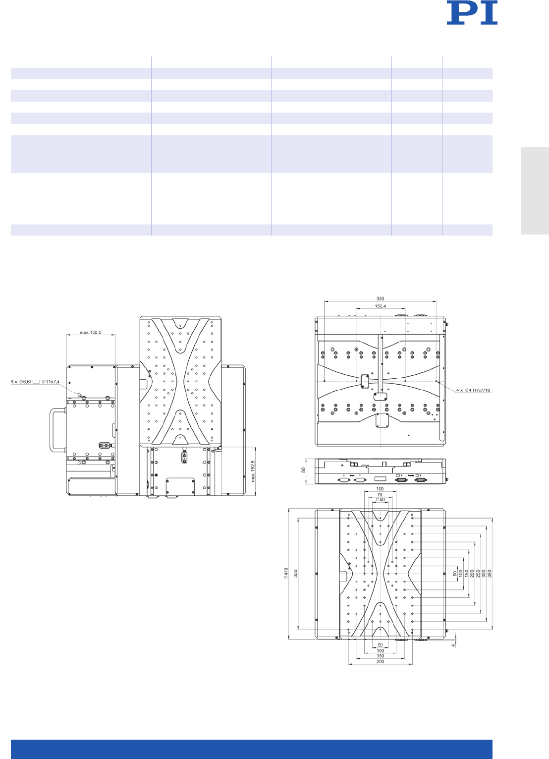
MOTION | POSITIONING
149
All cables required for operation with the ordered controller are included in the scope of delivery.
The cable length is 3 m. Cable for connecting to other controllers can be ordered as accessory.
Ask about custom designs!
Stages with stepper motor L-741.131100 / L-741.131112 L-741.131111 Unit Tolerance
Miscellaneous
Operating temperature range 5 to 40 5 to 40 °C
Material Aluminum, black anodized Aluminum, black anodized
Mass 27.5 27.5 kg ±5 %
Moved mass in X, unloaded 19.9 19.9 kg ±5 %
Moved mass in Y, unloaded 6.1 6.1 kg ±5 %
Connection L-741.131100. 2 × HD Sub-D
26 (m) (motor)
L-741.131112. 2 × HD Sub-D
26 (m) (motor/sensor)
2 × HD Sub-D 26 (m) (motor)
2 × Sub-D 15 (f) (sensor)
Recommended controllers / drivers C-663.12 (single axis)
SMC Hydra (double axis)
C-885 with C-663.12C885
(up to 20 axes)
ACS modular controller
SMC Hydra (double axis)
ACS modular controller
L-741, dimensions in mm
XY Stages
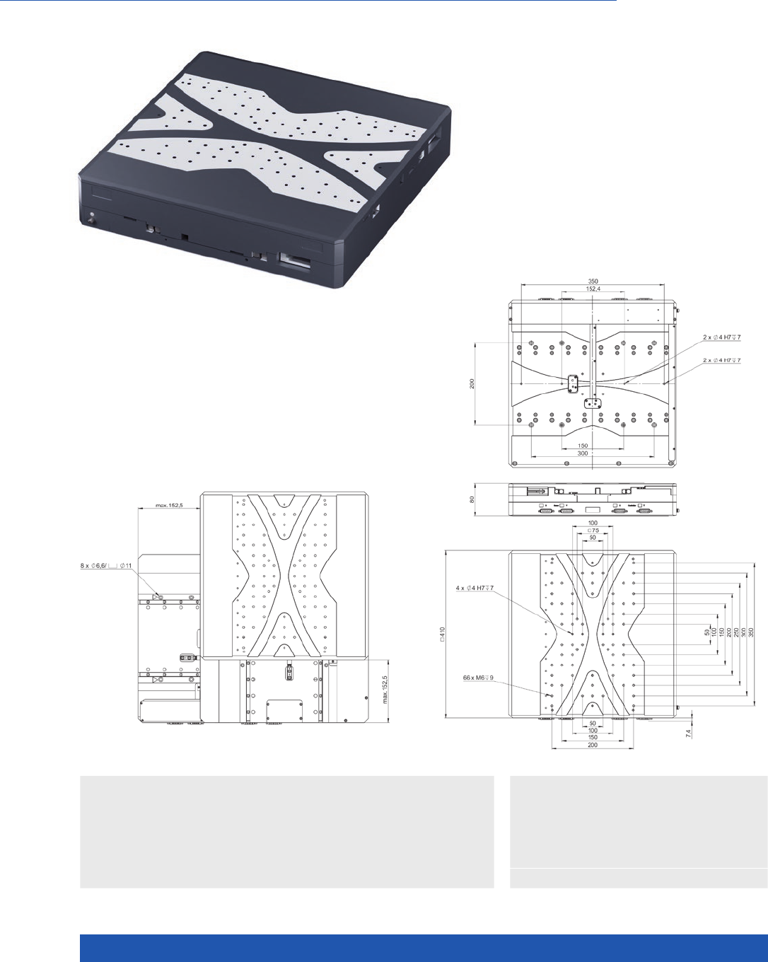
WWW.PI.WS
150
High Travel Accuracy and Stability, 305 mm × 305 mm Travel Range, Magnetic Direct Drive
V-741 PIMag® High-Precision XY Stage
n Travel range 305 mm × 305 mm (12”)
n Unidirectional repeatability to 0.1 µm
n Ironless 3-phase linear motor
n Velocity to 200 mm/s
n Incremental linear encoder with 1 nm resolution
n Crossed roller guides, anti-creep
>> Linear Encoder
>> PIMag® Magnetic Linear Motors
Technology Glossary ...................... page 290
V-741, dimensions in mm
Applications
n Automated Optical Inspection (AOI)
n Biotechnology
n Laser Cutting
n Laser Marking
n Medical Industry
n Metrology / Testing
n Scanning

MOTION | POSITIONING
151
V-741.136111 Unit Tolerance
Motion and positioning
Active axes X, Y
Travel range 305 × 305 mm
Integrated sensor Incremental linear encoder
Design resolution 0.001 µm
Sensor signal Sin/cos, 1 V peak-peak,
20 µm signal period
Minimum incremental motion 0.02 µm typ.
Unidirectional repeatability 0.1 µm typ.
Bidirectional repeatability ±0.25 µm typ.
Angular error xry (pitch) ±70 µrad typ.
Angular error xrz (yaw) ±50 µrad typ.
Angular error yrx (pitch) ±60 µrad typ.
Angular error yrz (yaw) ±50 µrad typ.
Orthogonality ±96.963 µrad typ.
Straightness / flatness ±3 µm typ.
Velocity 200 mm/s max.
Acceleration in X, without load 3 m/s² max.
Acceleration in Y, without load 9 m/s² max.
Reference and limit switches Optical
Mechanical properties
Load capacity 50 N max.
Permissible torque in θX, θY125 N·m max.
Permissible torque in θZ125 N·m max.
Guide Crossed roller guide with
anti-creep system
Drive properties
Motor type Ironless 3-phase linear motor
Operating voltage, nominal 48 V nom.
Operating voltage, max. 48 V max.
Peak force 80 N max.
Nominal force 29 N typ.
Peak current, effective 5 A typ.
Nominal current, effective 1. 5 A typ.
Force constant, effective 19.9 N/A typ.
Motor constant 4.89 N/√W typ.
Electrical time constant 0.4 ms
Resistance phase-phase 11 Ω typ.
Inductance phase-phase 3.6 mH typ.
Back EMF phase-phase 16 V·s/m max.
Pole pitch N-N 30 mm
Miscellaneous
Operating temperature range 5 to 40 °C
Material Aluminum, black anodized
Moved mass in X 25.5 kg ±5 %
Moved mass in Y 9.2 kg ±5 %
Overall mass 33 kg ±5 %
MTBF 20000 h
Connection 2 × HD Sub-D 26 (m) (motor)
2 × Sub-D 15 (f) (sensor)
Recommended controller SMC Hydra (double axis)
C-891 (single axis)
C-885 with C-891.10C885 (up to 20 axes)
ACS modular controller
All cables required for operation with the ordered controller are included in the scope of delivery.
The cable length is 3 m. Cable for connecting to other controllers can be ordered as accessory.
Ask about custom designs!
XY Stages
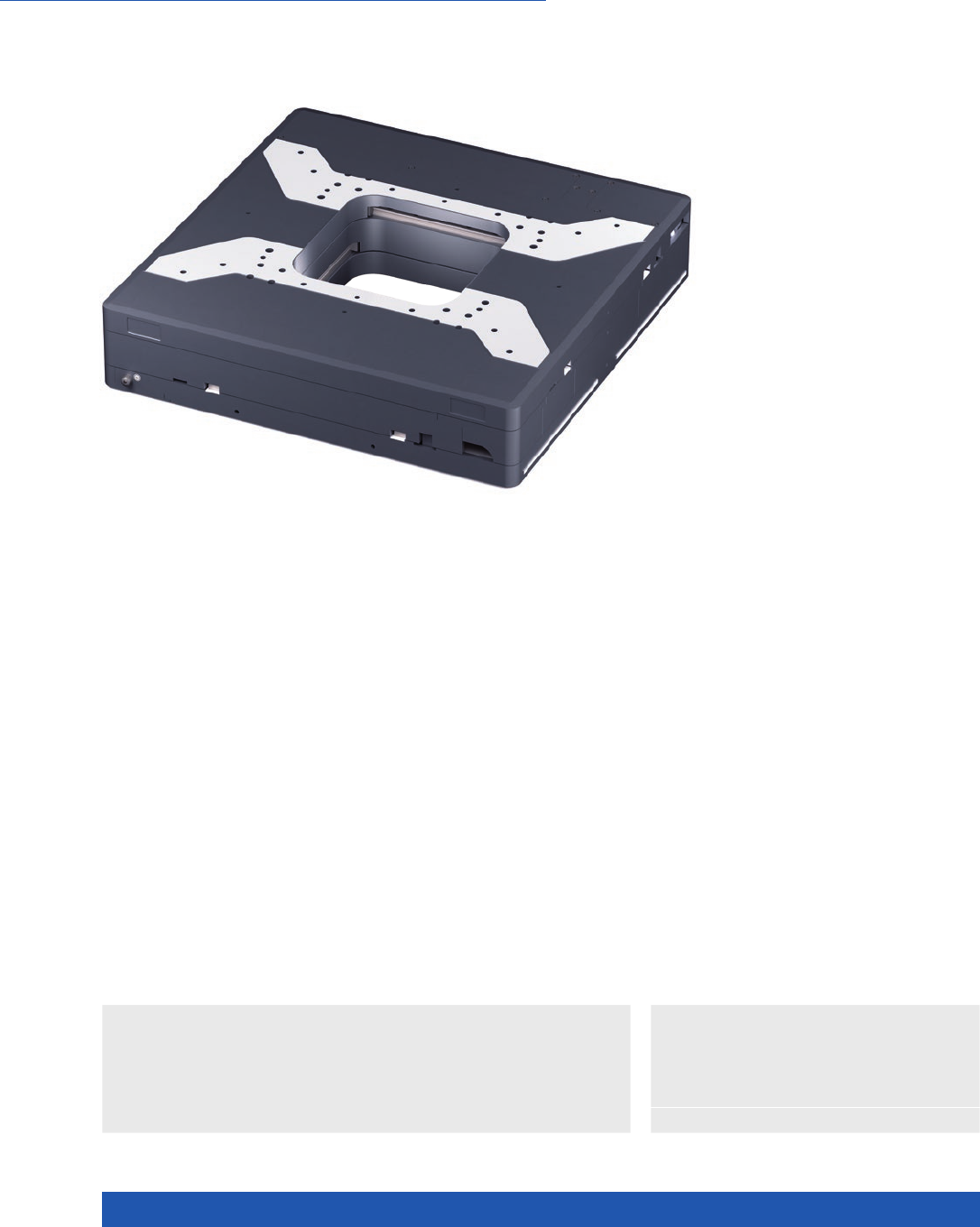
WWW.PI.WS
152
Clear Aperture, High Travel Accuracy, and Stability
L-738 Precision XY Stage
n Travel range 102 mm × 102 mm (4”)
n Large aperture, 150 mm × 150 mm
n Unidirectional repeatability to 0.05 µm
n Velocity to 90 mm/s
n 2-phase stepper motors, DC motors
n Incremental linear encoder with
1 nm resolution
>> Incremental Encoder
Technology Glossary ...................... page 290
Drive types
n 2-phase stepper motor for high torque even
at low velocities and higher resolution
n DC motor for high velocity constancy, low
vibration, and high velocities
Highly accurate position measuring with incremental linear encoder
Noncontact optical linear encoders measure the actual position directly at the
motion platform with the greatest accuracy so that nonlinearity, mechanical
play or elastic deformation have no influence on position measuring. Optical
reference points and limit switches.
Recirculating ball bearings
When carefully assembled, recirculating ball bearings are distinguished by a
beneficial combination of high load capacity, lifetime, maintenance-free opera-
tion, and guiding accuracy. The moving part of the stages is supported by four
preloaded linear ball bearing units which run on two guide rails. Each bearing
unit is made up of two independent rows of circulating ball bearings.
Applications
n Biotechnology
n Laser Cutting
n Laser Marking
n Medical Industry
n Metrology / Testing

MOTION | POSITIONING
153
Stages with DC motor L-738.053111 / L-738.053112 / L-738.053132 Unit Tolerance
Motion
Active axes X, Y
Travel range 102 × 102 mm
Angular error xry (pitch) ±40 µrad typ.
Angular error xrz (yaw) ±20 µrad typ.
Angular error yrx (pitch) ±40 µrad typ.
Angular error yrz (yaw) ±20 µrad typ.
Straightness / flatness ±2 µm typ.
Orthogonality ±96.963 µrad typ.
Velocity L-738.0 53111 / L-738.053112: 50
L-738.053132: 90
mm/s max.
Stages with DC motor L-738.053xxx Unit Tolerance
Mechanical properties
Drive screw type Ball screw
Drive screw pitch 2 mm
Guide type Recirculating ball bearing
Holding force, power off 20 N typ.
Push/pull force Fx, Fy power on 100 N max.
Load capacity 200 N max.
Permissible torque Mx in θX130 N·m max.
Permissible torque My in θY130 N·m max.
Permissible torque Mz in θZ90 N·m max.
Drive properties
Motor type DC motor
Operating voltage, nominal 24 V nom.
Operating voltage, max. 48 V max.
Stages with DC motor L-738.053111 L-738.053112 L-738.053132 Unit Tolerance
Positioning
Integrated sensor Incremental linear
encoder
Incremental linear
encoder
Incremental rotary
encoder
Sensor signal Sin/cos, 1 V peak-
peak, 20 µm signal
period
A/B quadrature,
TTL
A/B quadrature,
TTL
Design resolution 0.001 0.01 0.1 µm
Sensor resolution rotary encoder – – 20000 Cts./rev.
Minimum incremental motion 0.1 0.1 0.4 µm typ.
Unidirectional repeatability 0.1 0.1 0.4 µm typ.
Bidirectional repeatability ±0.5 ±0.5 ±2 µm typ.
Reference point switch repeatability <1 <1 <1 µm typ.
Reference and limit switches Optical Optical Optical
XY Stages

WWW.PI.WS
154
Stages with stepper motor L-738.051100 / L-738.051111 / L-738.051112 Unit Tolerance
Motion
Active axes X, Y
Travel range 102 × 102 mm
Angular error xry (pitch) ±40 µrad typ.
Angular error xrz (yaw) ±20 µrad typ.
Angular error yrx (pitch) ±40 µrad typ.
Angular error yrz (yaw) ±20 µrad typ.
Straightness / flatness ±2 µm typ.
Orthogonality ±96.963 µrad typ.
Velocity 35 mm/s max.
Stages with stepper motor L-738.051xxx Unit Tolerance
Mechanical properties
Drive screw type Ball screw
Drive screw pitch 2 mm
Guide type Recirculating ball bearing
Holding force, power off 60 N typ.
Push/pull force FX, FY power on 100 N max.
Load capacity 200 N max.
Permissible torque Mx in θX130 N·m max.
Permissible torque My in θY130 N·m max.
Permissible torque Mz in θZ90 N·m max.
Drive properties
Motor type Stepper motor, 2-phase
Operating voltage, nominal 24 V nom.
Operating voltage, max. 48 V max.
Step resolution 200 Full steps/
rev.
Stages with stepper motor L-738.051100 L-738.051111 L-738.051112 Unit Tolerance
Positioning
Integrated sensor – Incremental linear
encoder
Incremental linear
encoder
Sensor signal – Sin/cos, 1 V peak-
peak, 20 µm signal
period
A/B quadrature,
TTL
Design resolution 10.0 0.001 0.01 µm
Minimum incremental motion 0.2 0.05 0.05 µm typ.
Unidirectional repeatability 0.2 0.05 0.05 µm typ.
Bidirectional repeatability ±2 ±0.5 ±0.5 µm typ.
Reference point switch repeatability <1 <1 <1 µm typ.
Reference and limit switches Optical Optical Optical
Stages with DC motor L-738.053111 L-738.053112 / L-738.053132 Unit Tolerance
Miscellaneous
Operating temperature range 5 to 40 5 to 40 °C
Material Aluminum, black anodized Aluminum, black anodized
Mass 24 24 kg ±5 %
Moved mass in X, unloaded 14.6 14.6 kg ±5 %
Moved mass in Y, unloaded 5.8 5.8 kg ±5 %
Connection 2 × HD Sub-D 26 (m) (motor)
2 × Sub-D 15 (f) (sensor)
2 × HD Sub-D 26 (m)
(motor/sensor)
Recommended controllers / drivers SMC Hydra (double axis)
C-891 (single axis)
C-885 with C-891.10C885
(up to 20 axes)
ACS modular controller
C-863 (single axis)
C-884 (up to 6 axes)
C-885 with C-863.20C885
(to 40 axes)
ACS modular controller
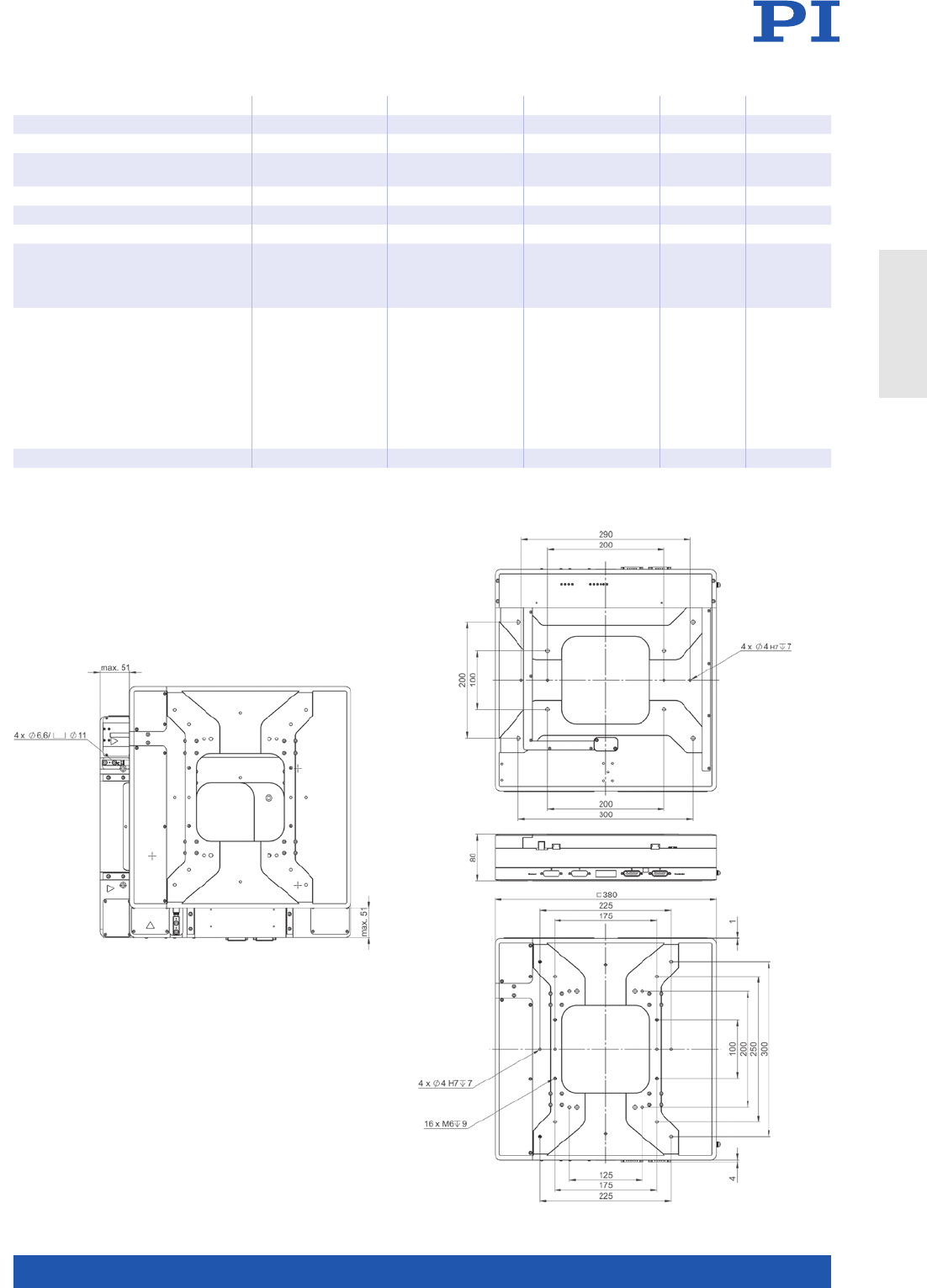
MOTION | POSITIONING
155
All cables required for operation with the ordered controller are included in the scope of delivery.
The cable length is 3 m. Cable for connecting to other controllers can be ordered as accessory.
Ask about custom designs!
Stages with stepper motor L-738.051100 L-738.051111 L-738.051112 Unit Tolerance
Miscellaneous
Operating temperature range 5 to 40 5 to 40 5 to 40 °C
Material Aluminum,
black anodized
Aluminum, b
lack anodized
Aluminum,
black anodized
Mass 22 22 22 kg ±5 %
Moved mass in X, unloaded 13.8 13.8 13.8 kg ±5 %
Moved mass in Y, unloaded 5.8 5.8 5.8 kg ±5 %
Connection 2 × HD Sub-D
26 (m) (motor)
2 × HD Sub-D
26 (m) (motor)
2 × Sub-D
15 (f) (sensor)
2 × HD Sub-D
26 (m) (motor/
sensor)
Recommended controllers / drivers C-663.12
(single axis)
SMC Hydra
(double axis)
C-885 with
C-663.12C885
(up to 20 axes)
ACS modular
controller
SMC Hydra
(double axis)
ACS modular
controller
C-663.12
(single axis)
C-885 with
C-663.12C885
(up to 20 axes)
ACS modular
controller
L-738, dimensions in mm
XY Stages
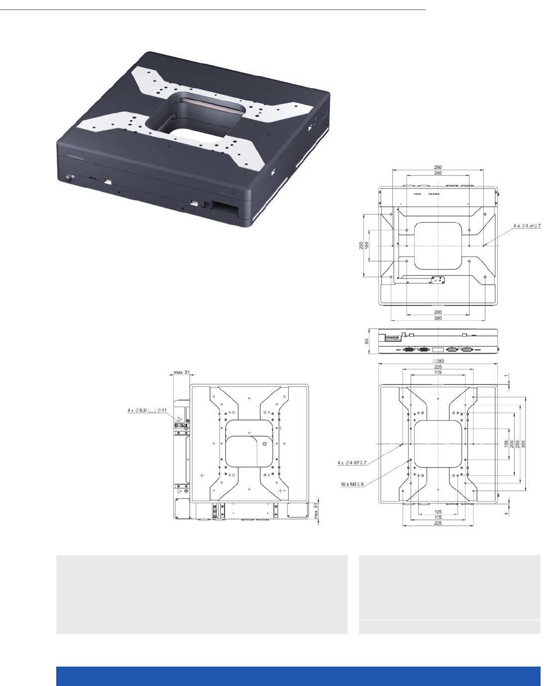
WWW.PI.WS
156
Clear Aperture, High Travel Accuracy and Stability, Magnetic Direct Drive
V-738 PIMag® High-Precision XY Stage
>> Incremental Encoder
>> PIMag® Magnetic Linear Motors
Technology Glossary ...................... page 290
V-738, dimensions in mm
Applications
n Automated Optical Inspection (AOI)
n Biotechnology
n Laser Cutting
n Laser Marking
n Medical Industry
n Metrology / Testing
n Scanning
n Travel range 102 mm × 102 mm (4”)
n Large aperture, 150 mm × 150 mm
n Unidirectional repeatability to 0.1 µm
n Velocity to 500 mm/s
n Ironless 3-phase linear motor
n Incremental linear encoder with 1 nm resolution

MOTION | POSITIONING
157
V-738.056111 Unit Tolerance
Motion and positioning
Travel range 102 × 102 mm
Integrated sensor Incremental linear encoder
Design resolution 0.001 µm
Sensor signal Sin/cos, 1 V peak-peak,
20 µm signal period
Minimum incremental motion 0.02 µm typ.
Unidirectional repeatability 0.1 µm typ.
Bidirectional repeatability ±0.25 µm typ.
Angular error xry (pitch) ±40 µrad typ.
Angular error xrz (yaw) ±20 µrad typ.
Angular error yrx (pitch) ±40 µrad typ.
Angular error yrz (yaw) ±20 µrad typ.
Straightness / flatness ±2 µm typ.
Orthogonality ±96.963 µrad typ.
Velocity 500 mm/s max.
Acceleration in X, Y, without load 10 m/s² max.
Reference and limit switches Optical
Mechanical properties
Load capacity 100 N max.
Permissible torque in θX, θY130 N·m max.
Permissible torque in θZ90 N·m max.
Guide Recirculating ball bearing
Drive properties
Motor type Ironless 3-phase linear motor
Operating voltage, nominal 48 V nom.
Operating voltage, max. 48 V max.
Peak force 200 N max.
Nominal force 87 N typ.
Peak current, effective 15 A typ.
Nominal current, effective 4.4 A typ.
Motor constant 71 N/√W typ.
Electrical time constant 0.4 ms
Resistance phase-phase 3.6 Ω typ.
Inductance phase-phase 1.2 mH typ.
Back EMF phase-phase 16 V·s/m max.
Pole pitch N-N 30 mm
Miscellaneous
Operating temperature range 5 to 40 °C
Material Aluminum, black anodized
Moved mass in X, unloaded 16.8 kg ±5 %
Moved mass in Y, unloaded 8 kg ±5 %
Overall mass 24 kg ±5 %
Connection 2 × HD Sub-D 26 (m) (motor)
2 × Sub-D 15 (f) (sensor)
h
Recommended controller SMC Hydra (double axis)
C-891 (single axis)
C-885 with C-891.10C885 (up to 20 axes)
ACS modular controller
All cables required for operation with the ordered controller are included in the scope of delivery.
The cable length is 3 m. Cable for connecting to other controllers can be ordered as accessory.
Ask about custom designs!
XY Stages
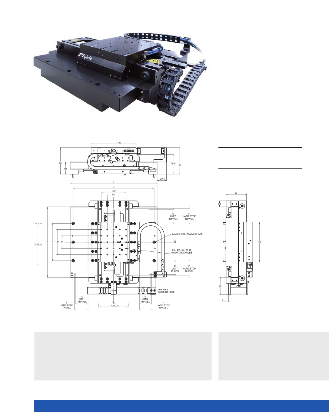
WWW.PI.WS
158
High-Performance, Compact XY Nanopositioning System
A-311 PIglide IS Planar Scanner with Air Bearing
n Ideal for scanning applications or
high-precision positioning
n Cleanroom compatible
n Travel ranges to 200 mm × 200 mm
n Load capacity to 147 N
n Low profile
n Resolution to 1 nm
n Optional granite base plates
>> Absolute Encoder
>> Incremental Encoder
>> PIglide Air Bearing Technology
>> PIMag® Magnetic Linear Motors
Technology Glossary ...................... page 290
Applications
n Electronics Manufacturing
n Laser Marking
n Scanning
n Scientific Instrumentation
n Semiconductor
A-311.xxx, dimensions in mm
A B C D E F
A-311.Dx x
A-311.A x x
A-311.Bxx
A-311.Cx x
300
350
400
450
232
282
332
382
100
150
200
250
275
325
375
425
25
50
75
100
30
55
80
105

MOTION | POSITIONING
159
A-311.Dxx A-311.Axx A-311.Bxx A-311.Cxx Unit Tolerance
Motion
Travel range 50 × 50 100 × 100 150 × 150 200 × 200 mm
Pitch (1) 20 30 40 50 µrad max.
Yaw (1) 510 15 20 µrad max.
Straightness (1) ±0.25 ±0.25 ±0.5 ±0.5 µm max.
Straightness per 10 mm
travel range (1)
±10 ±10 ±10 ±10 nm max.
Flatness (1) ±0.5 ±0.5 ±1 ±1 µm max.
Flatness per 10 mm travel
range (1)
±10 ±10 ±10 ±10 nm max.
XY orthogonality 25 25 25 25 µrad max.
Velocity, unloaded (2) 2 2 2 2 m/s max.
Acceleration of the upper axis,
unloaded (2)
27.5 27.5 27.5 27.5 m/s² max.
Acceleration of the lower axis,
unloaded (2)
15 13 11 10 m/s² max.
Mechanical properties
Load capacity in z (3) 147 147 147 147 N max.
Moved mass, upper axis 3 3 3 3 kg
Moved mass, lower axis 5.5 6.5 7. 5 8.5 kg
Overall mass 14.5 18.5 22.5 27.5 kg
A-311.xAx A-311.xBx A-311.xCx
Positioning
Integrated sensor Incremental linear encoder Absolute encoder Incremental linear encoder
Sensor signal Sin/cos, 1 V peak-peak,
20 µm signal period
BiSS-C A/B quadrature, TTL
Sensor resolution 1.2 nm (4) 1 nm 50 nm
Bidirectional repeatability ±0.05 µm (4) ±0.05 µm ±0.05 µm
Accuracy, uncompensated (5) A-311.Dxx: ±1 µm
A-311.Axx: ±1.5 µm
A-311.Bxx: ±2 µm
A-311.Cxx: ±2.5 µm
A-311.Axx: ±1.5 µm
A-311.Axx: ±1.5 µm
A-311.Axx: ±1.5 µm
A-311.Axx: ±1.5 µm
A-311.Dxx: ±1 µm
A-311.Axx: ±1.5 µm
A-311.Bxx: ±2 µm
A-311.Cxx: ±2.5 µm
Accuracy, with error
compensation (5)
±0.5 µm ±0.5 µm ±0.5 µm
A-311 Unit Tolerance
Drive properties
Drive type Linear motor, ironless, 3-phase
Intermediate circuit voltage,
effective
48, nominal
80, max.
V DC
Peak force 85 N typ.
Nominal force 39 N typ.
Force constant, effective 12.3 N/A typ.
Resistance phase-phase 3.6 Ω
Inductivity phase-phase 1.24 mH
Back EMF phase-phase 10.1 V·s/m max.
Cabling External, movable drag chain
Miscellaneous
Operating pressure (6) 60 to 70 psi (415 to 485 kPa)
Air consumption <2 SCFM (56 SLPM)
Air quality see A-322 datasheet, next page
Materials Hardcoat aluminum, stainless steel fasteners
(1) Dependent on the flatness of the surface, on which the stage is mounted.
(2) Can be limited by the payload, controller or drive.
(3) Assumes payload CG is centered no more than 50 mm above the motion platform. The stage is designed for horizontal operation only.
(4) Assumes 16384x interpolation. Contact PI for the use of other factors.
(5) Improved accuracy can be obtained with controller-based error compensation. The stage must be ordered with a controller from PI to reach these values.
Accuracy values assume short-term duration and do not consider the long-term effects of thermal drift on the stage.
(6) To protect the stage against damage, it is recommended to connect an air pressure sensor to the Motion-Stop input of the controller.
All specifications apply per axis, if not otherwise described.
XY Stages
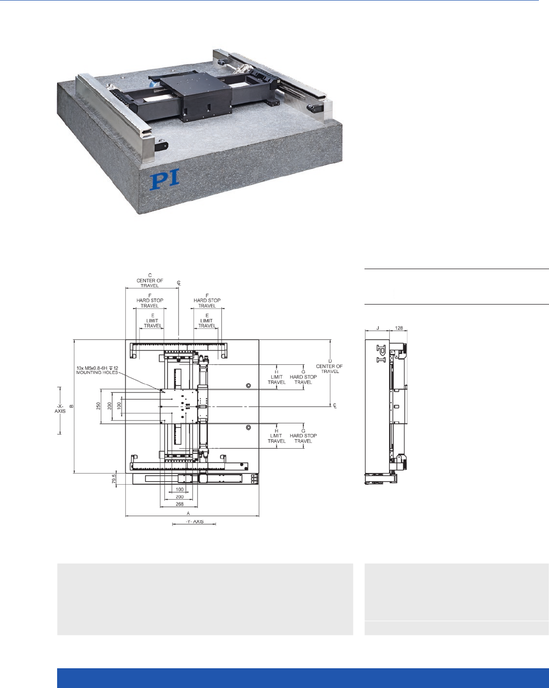
WWW.PI.WS
160
XY Positioning System with 1 nm Resolution
A-322 PIglide HS Planar Scanner with Air Bearing
n Ideal for scanning applications or
high-precision positioning
n Cleanroom compatible
n Travel ranges to 500 mm × 1000 mm
n Load capacity to 245 N
n Resolution to 1 nm
n Velocity up to 2 m/s
>> Absolute Encoder
>> PIglide Air Bearing Technology
>> PIMag® Magnetic Linear Motors
Technology Glossary ...................... page 290
Applications
n Electronics Manufacturing
n Laser Cutting
n Scanning
n Scientific Instrumentation
n Semiconductor
A-322.xxx, dimensions in mm A B C D E F G H J
A-322.Axx
A-322.Bxx
A-322.Cxx
A-322.Dxx
960
1110
1110
1610
960
960
1110
1110
348
459
459
709
480
480
555
555
175
250
250
500
200
275
275
525
182
182
257
257
175
175
250
250
175
175
250
250

MOTION | POSITIONING
161
A-322
Drive properties
Drive type Linear motor, ironless, 3-phase, 1 × to bridge axis, 2 × to gantry axis
Intermediate circuit voltage,
effective
48, nominal
80, max.
VDC
Peak force # 298 N typ.
Nominal force # 87 N typ.
Force constant, effective # 19.9 N/A typ.
Resistance phase-phase # 3.6 Ω
Inductivity phase-phase # 1.2 mH
Back EMF phase-phase # 16 V·s/m max.
Cabling moved ribbon cable, cleanroom compatible
Motion and positioning
Operating pressure ## 80 psi (552 kPa)
Air consumption with
external vacuum supply
<2 SCFM (56 SLPM)
Air consumption with
internal vacuum supply
<3.2 SCFM (100 SLPM)
Vacuum 10.8 psi (74.7 kPa), <0.5 SCFM (14 SLPM)
Air quality Clean (filtered to 1.0 µm or better) – ISO 8573-1
Class 1 Oil free – ISO 8573-1 Class 1
Dry (–15 °C dew point) – ISO 8573-1 Class 3
Materials Hardcoat aluminum and nickel-plated steel with stainless steel
mounting material, granite base
* Improved accuracy can be obtained with controller-based error compensation. Stage must be ordered with controller.
Accuracy values assume short-term time duration and do not consider the long-term effects of thermal drift on the stage.
** Unloaded. Can be limited by the insulating system payload, controller or drive.
*** Assumes payload CG is centered no more than 50 mm above the stage table.
# Specifications for the drive apply per motor. Two motors are located at the gantry axis.
## To protect the stage against damage, it is recommended to connect an air pressure sensor to the Motion-Stop input of the controller.
All specifications apply per axis, if not otherwise described.
A-322.Axx A-322.Bxx A-322.Cxx A-322.Dxx Unit Tolerance
Motion and positioning
Active axes X, Y X, Y X, Y X, Y
Travel range
(bridge axis × gantry axis)
350 × 350 350 × 500 500 × 500 500 × 1000 mm
Integrated sensors Absolute
Encoders
Absolute
Encoders
Absolute
Encoders
Absolute
Encoders
Sensor resolution 1 1 1 1 nm
Bidirectional repeatability ±0.08 ±0.08 ±0.08 ±0.08 µm max.
Accuracy* ±0.5 ±0.5 ±0.5 ±0.5 µm max.
Pitch 15 20 30 40 µrad max.
Yaw* 5 5 7 7 µrad max.
Straightness* ±0.5 ±0.5 ±1 ±1 µm max.
Straightness per
10 mm travel range*
±10 ±10 ±10 ±10 nm max.
Flatness ±0.5 ±1 ±1.5 ±2.5 µm max.
Flatness per 10 mm travel
range
±10 ±10 ±10 ±10 nm max.
XY orthogonality 25 25 25 25 µrad max.
Velocity** 2 2 2 2 m/s max.
Acceleration, bridge axis** 20 20 20 20 m/s² max.
Acceleration, gantry axis** 15 15 12 12 m/s² max.
Mechanical properties
Load capacity in Z*** 245 245 245 245 N max.
Moved mass, bridge axis 14 14 14 14 kg
Moved mass, gantry axis 40 40 43 43 kg
Overall mass 610 700 1075 1525 kg
Guide type Air bearings Air bearings Air bearings Air bearings
XY Stages
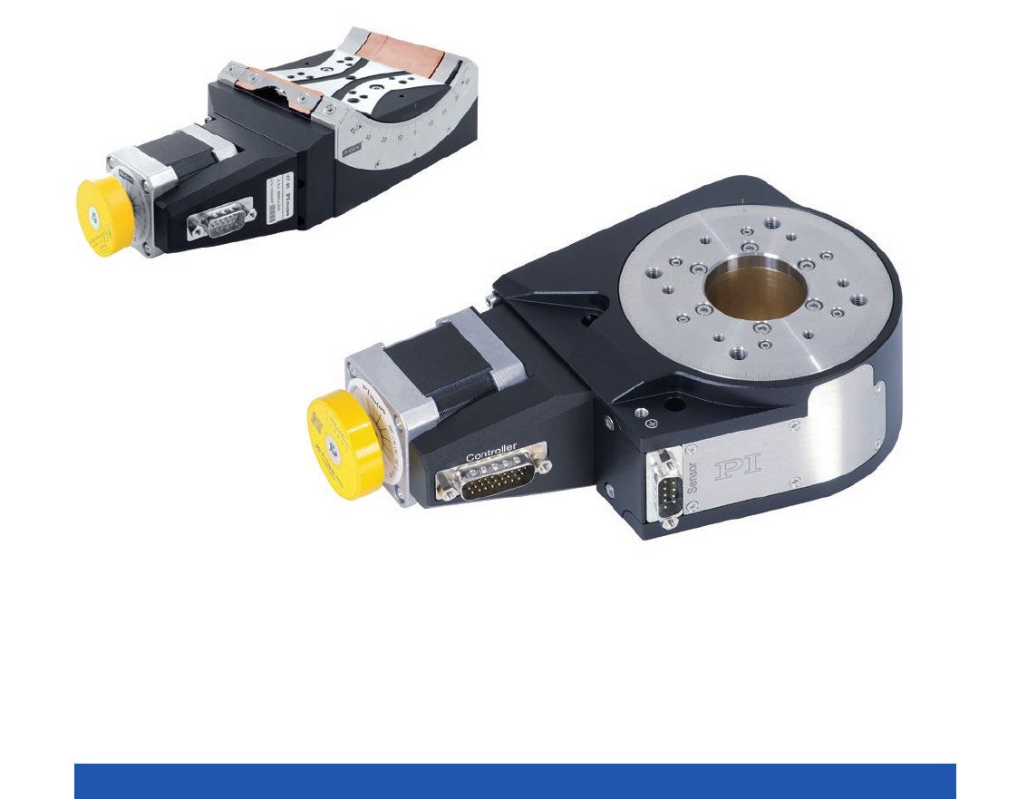
WWW.PI.WS
162
Rotation Stages

MOTION | POSITIONING
163
Rotation Stages ....................................................................................................................................................................... 164
M-116 Precision Rotation Stage .................................................................................... 164
RS-40 Compact Rotation Stage ..................................................................................... 166
DT-34 Miniature Rotation Stage .................................................................................... 168
DT-80 Compact Rotation Stage ..................................................................................... 170
M-060 / M-061 / M-062 Precision Rotation Stage ........................................................... 172
L-611 Precision Rotation Stage ...................................................................................... 174
PRS-200 Precision Rotation Stage ................................................................................. 178
UPR-100 Ultraprecision Rotation Stage ......................................................................... 180
UPR-120 Ultraprecision Rotation Stage ......................................................................... 182
Rotation Stages with Torque Motor and Air Bearing ............................................................................................................. 184
UPR-120 Air Ultraprecision Rotation Stage with Air Bearing ......................................... 184
A-62x PIglide RM Rotation Stage with Air Bearings ...................................................... 186
A-63x PIglide RL Low-Profile Rotation Stage with Air Bearing ...................................... 190
Goniometer Stages .................................................................................................................................................................. 192
WT-85 Motorized Precision Goniometer ........................................................................ 192
WT-100 Motorized Precision Goniometer ...................................................................... 194
WT-90 Motorized Precision Goniometer ........................................................................ 196
WT-120 Motorized Precision Goniometer ...................................................................... 198
Rotation Stages
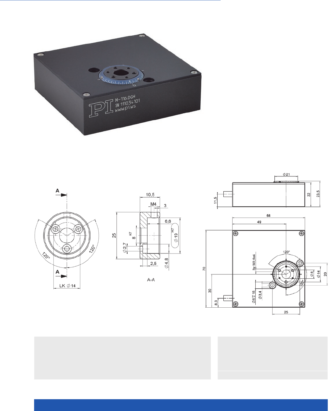
WWW.PI.WS
164
Compact, for Multi-Axis Combinations with M-110
M-116 Precision Rotation Stage
n Compact Design
n Unlimited travel range
n Clear aperture for transmitted-light
applications
n Backlash-compensated worm drive
n Compact multi-axis combinations with M-110
n Noncontact reference point switch
>> Incremental Encoder
Technology Glossary ...................... page 290
Applications
n Automation
n Precision Micro Assembly
n Scientific Instrumentation
M-116, dimensions in mmDimensions of the M-116.AL1 lens adapter for 0.5” optic devices such as polarizers.
Dimensions in mm. Note that the decimal places are separated by a comma in the
drawings.

MOTION | POSITIONING
165
M-116.DG M-116.DGH Unit Tolerance
Active axes Rotation Rotation
Motion and positioning
Rotation range >360 >360 °
Integrated sensor Rotary encoder Rotary encoder
Sensor resolution 2048 2048 Cts./rev.
Design resolution 2.45 (0.00013) 3.16 (0.00018) µrad (°)
Minimum incremental motion 50 25 µrad
Backlash 1000 500 µrad
Unidirectional repeatability 12 10 µrad
Velocity 20 20 °/s max.
Mechanical properties
Worm gear ratio 44:1 44:1
Gear ratio 28.444:1 22.0335:1
Load capacity / axial force ±15 ±15 N
Max. torque (θX, θY) ±1.5 ±1.5 N·m max.
Max. torque clockwise (θZ) 0.4 0.4 N·m max.
Max. torque counterclockwise
(θZ)
0.8 0.8 N·m max.
Drive properties
Motor type DC gear motor DC gear motor
Operating voltage 0 to ±12 0 to ±12 V
Motor power 1.75 1.75 W
Reference point switch Optical Optical
Miscellaneous
Operating temperature range –20 to 65 –20 to 65 °C
Material Aluminum Aluminum
Mass 0.4 0.4 kg
Recommended controllers /
drivers
C-863
C-884
C-863
C-884
Ask about custom designs!
Rotation Stages
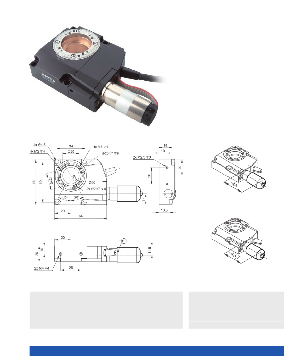
WWW.PI.WS
166
Precision Positioning
RS-40 Compact Rotation Stage
n Unlimited travel range
n Repeatability to 87 µrad
n 20 mm Ø aperture
n Reference point switch
>> Incremental Encoder
Technology Glossary ...................... page 290
Applications
n Automation
n Precision Micro Assembly
n Scientific Instrumentation
RS-40 rotation stage, DC motor,
dimensions in mm
RS-40 rotation stage, stepper motor,
dimensions in mm
RS-40 rotation stage, dimensions in mm
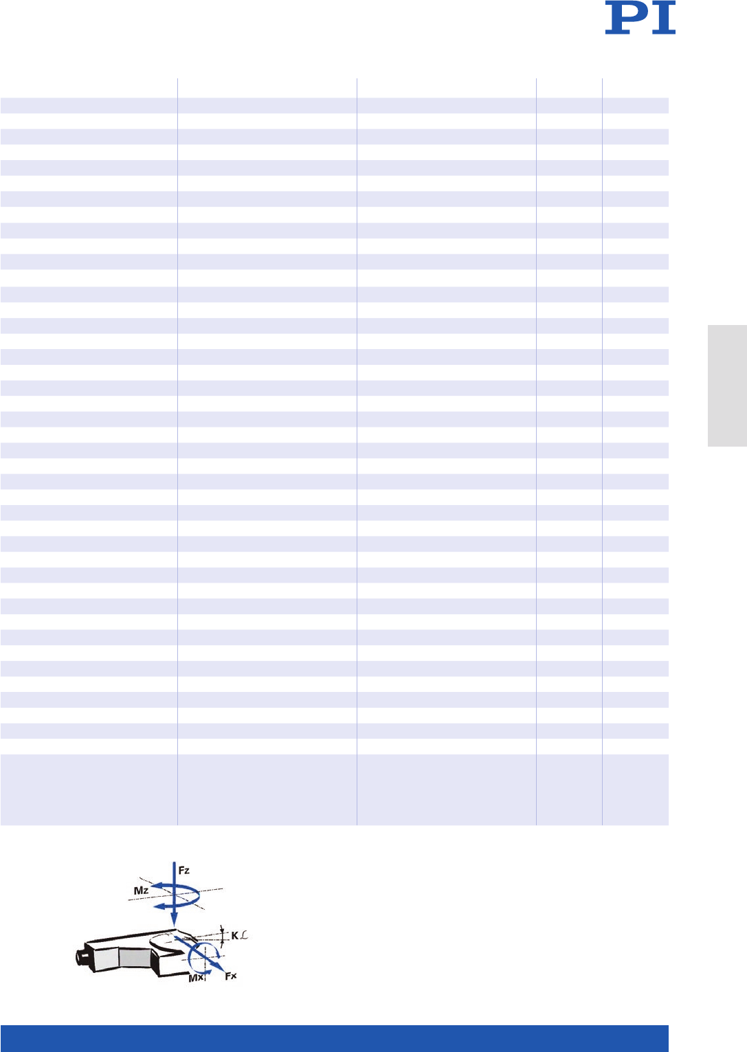
MOTION | POSITIONING
167
321691001-0000 321692001 Unit Tolerance
With DC motor With stepper motor
Active axes Rotation Rotation
Motion and positioning
Rotation range >360 >360 °
Design resolution 0.45 38 µrad
Sensor resolution rotary encoder 2048 – Cts./rev.
Minimum incremental motion 87 87 µrad typ.
Unidirectional repeatability 87 87 µrad typ.
Bidirectional repeatability ±700 ±700 µrad typ.
Angular velocity 7 5 °/s max.
Eccentricity ±5 ±5 µm typ.
Flatness ±5 ±5 µm typ.
Wobble ±35 ±35 µrad typ.
Mechanical properties
Bearing Ball bearings Ball bearings
Gear ratio 76:1 76:1
Worm gear ratio 90:1 90:1
Load capacity / axial force 20 20 N max.
Permissible lateral force 5 5 N max.
Holding torque in θZ, power off 0.20 0.20 N·m typ.
Permissible torque Mx in θX, θY2 2 N·m max.
Torque MZ in θZ, power on 0.2 0.2 N·m max.
Moment of inertia 0.0155 0.0155 kg·mm² ±20 %
Drive properties
Motor type DC motor 2-phase stepper motor
Operating voltage, nominal 12 24 V nom.
Operating voltage, max. 24 24 V max.
Nominal current, effective 0.04 – A typ.
Peak current, effective 0.16 – A typ.
Torque constant, effective 0.00826 – N·m/A typ.
Electrical time constant 35 – ms
Resistance phase-phase 60 12.5 Ω typ.
Inductance phase-phase 0.4 6.3 mH typ.
Back EMF phase-phase – 4.4 V/kRPM max.
Reference point switch Hall effect Hall effect
Miscellaneous
Operating temperature range 5 to 40 5 to 40 °C
Material Aluminum Aluminum
Mass 0.4 0.4 kg
Moved mass 0.088 0.088 kg
MTBF 10000 10000 h
Connection Sub-D 15 (m) HD Sub-D 15 (m)
Recommended controllers /
drivers
C-863 (single axis)
C-884 (up to 6 axes)
C-885 with C-863.20C885
(to 40 axes)
ACS modular controller
C-663.12 (single axis)
SMC Hydra (double axis)
C-885 with C-663.12C885
(up to 20 axes)
ACS modular controller
Connecting cables for motor and sensor are not in the scope of delivery and must be ordered separately.
Ask about custom designs!
Direction of the axes and
torques for rotation stages
Rotation Stages
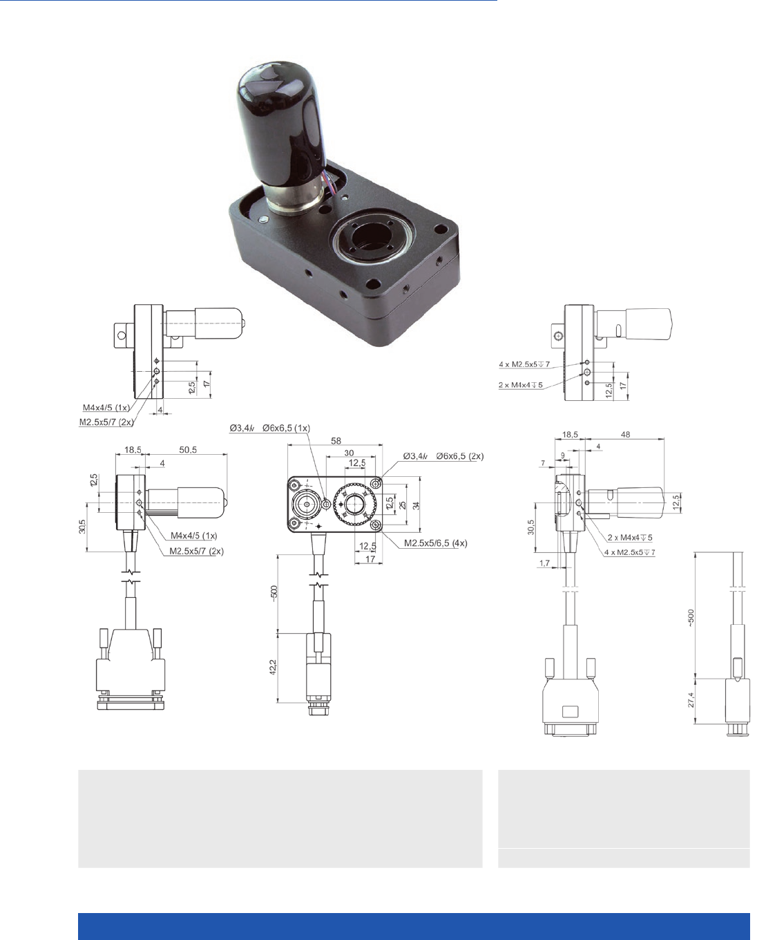
WWW.PI.WS
168
Compact Dimensions, with DC or Stepper Motor
DT-34 Miniature Rotation Stage
n Clear aperture, 10 mm Ø
n Compact design
n Unidirectional repeatability to 350 µrad
n Angular velocity to 675 °/s
n Integrated optical reference point switch
>> Incremental Encoder
Technology Glossary ...................... page 290
Applications
n Automation
n Precision Micro Assembly
n Scientific Instrumentation
DT-34 with DC motor,
dimensions in mm
DT-34 with stepper motor,
dimensions in mm

MOTION | POSITIONING
169
3215910030 3215920030-0000 Unit Tolerance
With DC motor With stepper motor
Active axes θZθZ
Motion and positioning
Rotation range 360 360 °
Design resolution 69.62 1724.8 µrad
Integrated sensor Rotary encoder –
Sensor resolution rotary encoder 2048 – Cts./rev.
Minimum incremental motion 700 350 µrad typ.
Unidirectional repeatability 700 350 µrad typ.
Bidirectional repeatability ±1400 ±1000 µrad typ.
Angular velocity 675 195 °/s max.
Eccentricity ±50 ±50 µm typ.
Flatness ±8 ±8 µm typ.
Wobble ±100 ±100 µrad typ.
Reference point switch Optical Optical
Mechanical properties
Bearing Ball bearings Ball bearings
Worm gear ratio 24986:567 774566:5103
Load capacity / axial force FZ15 15 N max.
Permissible lateral force FX, FY2.5 2.5 N max.
Permissible torque Mx in θX, θY2.5 2.5 N·m max.
Drive properties
Drive torque 0.9 0.3 N·m max.
Motor type DC motor 2-phase stepper motor
Operating voltage, nominal 12 12 V nom.
Operating voltage, max. 48 48 V max.
Step resolution – 24 Full steps/
rev.
Miscellaneous
Operating temperature range 5 to 40 5 to 40 °C
Material Aluminum, black anodized Aluminum, black anodized
Mass 0.15 0.15 kg ±5 %
Moved mass 0.1 0.1 kg ±5 %
Connection Sub-D 15 (m) Sub-D 15 (m)
Recommended controllers /
drivers
C-863 (single axis)
C-884 (up to 6 axes)
C-885 with C-863.20C885
(to 40 axes)
ACS modular controller
C-663.12 (single axis)
SMC Hydra (double axis)
C-885 with C-663.12C885
(up to 20 axes)
ACS modular controller
Connecting cables for motor and sensor are not in the scope of delivery and must be ordered separately.
Ask about custom designs!
Rotation Stages
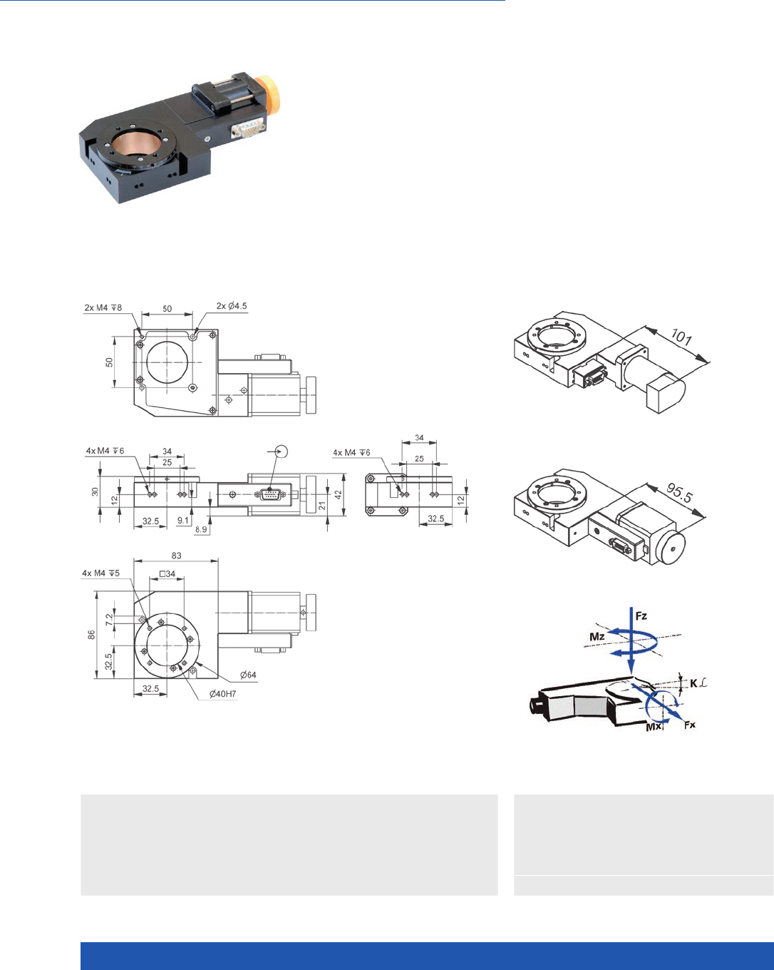
WWW.PI.WS
170
Large clear aperture
DT-80 Compact Rotation Stage
n Unlimited travel range
n Repeatability to 175 µrad
n Maximum velocity 40°/s
n Reference point switch
DT-80 rotation stage, dimensions in mm
>> Incremental Encoder
Technology Glossary ...................... page 290
Applications
n Automation
n Precision Micro Assembly
n Scientific Instrumentation
DT-80 rotation stage, DC motor,
dimensions in mm
RS-80 rotation stage, stepper motor,
dimensions in mm
Direction of the
axes and torques for
rotation stages

MOTION | POSITIONING
171
64439100 64439200 Unit Tolerance
With DC motor With stepper motor*
Active axes θZθZ
Motion and positioning
Rotation range >360 >360 °
Design resolution 17.453 174.53 µrad
Integrated sensor Rotary encoder –
Sensor resolution rotary encoder 2000 – Cts./rev.
Minimum incremental motion 69.8 69.8 µrad typ.
Unidirectional repeatability 175 175 µrad typ.
Bidirectional repeatability ±3491 ±3491 µrad typ.
Angular velocity 40 30 °/s max.
Eccentricity ±30 ±30 µm typ.
Flatness ±30 ±30 µm typ.
Wobble ±100 ±100 µrad typ.
Mechanical properties
Worm gear ratio 180:1 180:1
Load capacity / axial force 20 20 N max.
Permissible lateral force 10 10 N max.
Permissible torque Mx in θX, θY5 5 N·m max.
Drive properties
Drive torque 0.1 0.1 N·m max.
Guide type Ball bearings Ball bearings
Motor type DC motor 2-phase stepper motor
Operating voltage, nominal 24 24 V nom.
Operating voltage, max. 48 48 V max.
Reference point switch mechanical mechanical
Miscellaneous
Operating temperature range 5 to 40 5 to 40 °C
Material Aluminum, black anodized,
red bronze
Aluminum, black anodized,
red bronze
Mass 0.8 0.8 kg ±5 %
Moved mass, unloaded 0.3 0.3 kg ±5 %
Connection HD Sub-D 15 (m) HD Sub-D 15 (m)
Recommended controllers /
drivers
C-863 (single axis)
C-884 (up to 6 axes)
C-885 with C-863.20C885
(to 40 axes)
ACS modular controller
C-663.12 (single axis)
SMC Hydra (double axis)
C-885 with C-663.12C885
(up to 20 axes)
ACS modular controller
* Max. 1.7 A/phase; 200 full step/rev.
Connecting cables for motor and sensor are not in the scope of delivery and must be ordered separately.
Ask about custom designs!
Rotation Stages
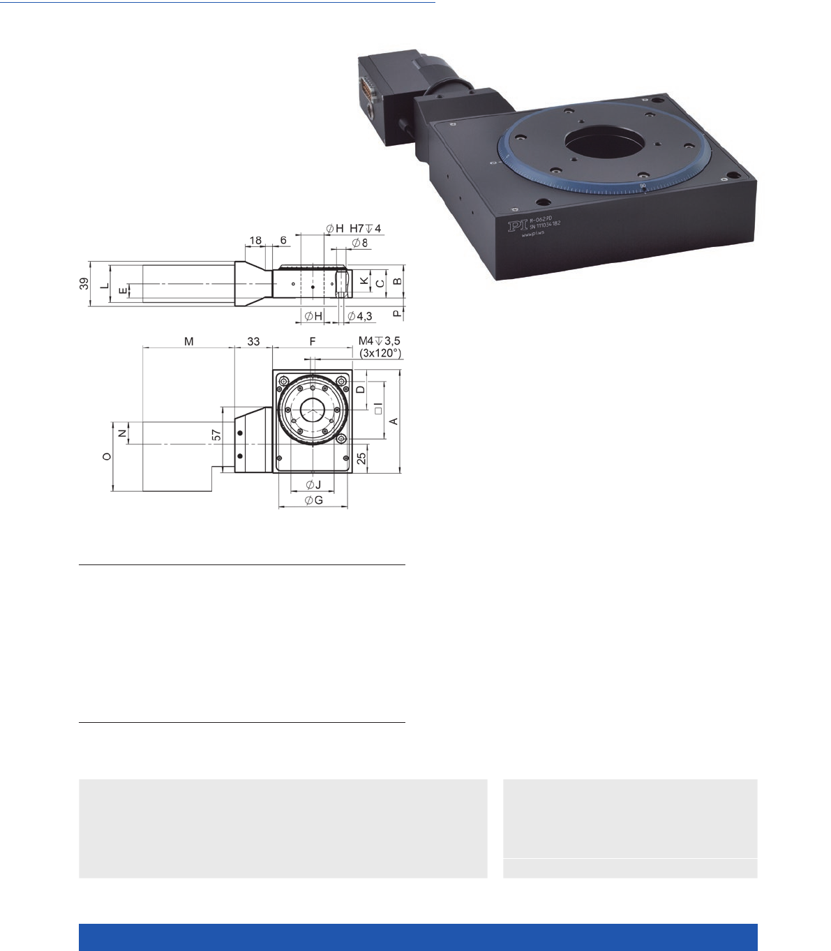
WWW.PI.WS
172
Unlimited Travel Range
>> ActiveDrive
>> Incremental Encoder
Technology Glossary ...................... page 290
Applications
n Optical Alignment
n Precision Micro Assembly
n Scientific Instrumentation
M-060 / M-061 / M-062
Precision Rotation Stage
DIMENSIONS M-060.PD M-060.DG M-061.PD M-061.DG M-062.PD M-062.DG
A
B
C
D
E
F
G
H
I
J
K
L
M
N
O
P
90
29
25
35
12,5
70
60
20
50
38
20
39
80,8
19
59,3
7
90
29
25
35
12,5
70
60
20
50
38
20
34
83,8
15
51
7
130
34
30
55
15
110
100
35
90
50
20
39
80,8
19
59,3
4,5
130
34
30
55
15
110
100
35
90
50
20
34
83,8
15
51
4,5
150
42
38
65
21,5
130
120
45
110
60
28
39
80,8
19
59,3
–
150
42
38
65
21,5
130
120
45
110
60
25
34
83,8
15
51
–
n Unlimited travel range
n Very high resolution
n Max. velocity 90°/s
n Backlash-compensated worm drive
n ActiveDrive or DC motor
n Direction-sensing reference point switch
M-06x, dimensions in mm

MOTION | POSITIONING
173
M-060.PD /
M-061.PD /
M-062.PD
M-060.DG /
M-061.DG /
M-062.DG
Unit Tolerance
Active axes Rotation Rotation
Motion and positioning
Rotation range >360 >360 °
Integrated sensor Rotary encoder Rotary encoder
Sensor resolution 4000 2000 Cts./rev.
Design resolution 32 (0.0018) /
17.5 (0.001) /
15 (0.0008)
2.1 (0.00012) /
1.2 (6.9 × 10⁻⁵) /
0.96 (5.5 × 10⁻⁵)
µrad (°)
Minimum incremental motion 32 / 17.5 / 15 6.3 / 6 / 5 µrad
Backlash 200 / 200 / 240 200 / 200 / 240 µrad
Unidirectional repeatability 50 / 50 / 60 50 / 50 / 60 µrad
Velocity 90 16 / 9 / 7.5 °/s max.
Mechanical properties
Worm gear ratio 50:1 / 90:1 / 110:1 50:1 / 90:1 / 110:1
Gear ratio – (28/12)4:1
Load capacity / axial force ±500 / ±550 / ±650 ±500 / ±550 / ±650 N
Max. torque θX, θY±6 / ±6 / ±7 ±6 / ±6 / ±7 N·m max.
Max. torque θZ±4 / ±6 / ±8 ±4 / ±6 / ±8 N·m max.
Drive properties
Motor type DC motor, ActiveDrive DC gear motor
Operating voltage 24 0 to ±12 V
Motor power 30 3 W
Reference point switch Hall effect Hall effect
Miscellaneous
Operating temperature range –10 to 40 –10 to 40 °C
Material Aluminum Aluminum
Mass 0.94 / 1.88 / 2.76 0.94 / 1.88 / 2.76 kg
Recommended controllers /
drivers
C-863 (single axis)
C-884 (up to 6 axes)
C-863 (single axis)
C-884 (up to 6 axes)
Rotation Stages
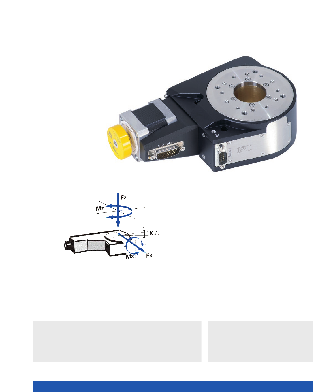
WWW.PI.WS
174
High Travel Accuracy
L-611 Precision Rotation Stage
n Unlimited travel range
n Very high resolution
n Maximum velocity 200°/s
n Optional angle measuring system for
direct position measurement
n ActiveDrive DC, DC, BLDC, and stepper motors
n Direction-sensing reference point switch
>> ActiveDrive
>> Incremental Encoder
>> Vacuum-Compatible Versions
Technology Glossary ...................... page 290
Applications
n Medical Industry
n Metrology / Testing
n Photonics
n Precision Micro Assembly
n Sample Inspection
Direction of the axes and
torques for rotation stages

MOTION | POSITIONING
175
L-611 Unit Tolerance
Motion
Active axes θZ
Rotation range >360 °
Wobble ±15 µrad
Flatness ±1 µm
Eccentricity ±2.5 µm
Angular velocity L-611.xxSD: 50
L-611.xxAD: 200
L-611.99xxxx: 200
°/s max.
L-611 Unit Tolerance
Mechanical properties
Bearing Ball bearings
Worm gear ratio 90:1
Load capacity / axial force 100 N max.
Permissible lateral force 50 N max.
Permissible torque Mx
in θX, θY
40 N·m max.
Permissible torque Mz
in θz
3 N·m max.
Moment of inertia 770 kg·mm² ±20 %
L-611.9ASD
L-611.993261
L-611.94AD L-611.90AD
L-611.xxx232
L-611.90SD Unit Tolerance
Positioning
Integrated sensor Incremental angle
measuring system
Incremental angle
measuring system
Rotary
encoder
–
Sensor signal Sin/cos,
1 V peak-peak
A/B quadrature,
TTL
A/B quadra-
ture, TTL
–
Sensor resolution
rotary encoder
––20000 – Cts./rev.
Sensor resolution angle
measuring system
9000 9000 – – Lines/
revolution
Design resolution 0.174 3.49 3.49 349 µrad
Minimum incremental
motion
L-611.9ASD: 0.87
L-611.993261: 3.5
17.45 35 8.72 µrad typ.
Unidirectional
repeatability
L-611.9ASD: 0.87
L-611.993261: 3.5
17.45 35 20 µrad typ.
Bidirectional repeatability ±3.5 ±17.45 ±175 ±175 µrad typ.
Reference point switch Hall effect Hall effect Hall effect Hall effect
Reference point switch
repeatability
<2 <2 <2 <2 µm typ.
Rotation Stages

WWW.PI.WS
176
L-611.xxSD L-611.xxAD L-611.xx3xxx L-611.xx5xxx Unit Tolerance
Drive properties
Motor type 2-phase stepper
motor *
DC motor with
PWM control
DC motor BLDC motor
Operating voltage,
nominal
24 24 24 24 V nom.
Operating voltage, max. 48 24 48 48 V max.
Motor resolution 200 – – – Full steps/
rev.
L-611.9xSD L-611.xxAD L-611.993xxx L-611.995232 Unit Tolerance
Miscellaneous
Operating temperature
range
5 to 40 5 to 40 5 to 40 5 to 40 °C
Material Aluminum,
black anodized,
stainless steel,
red bronze
Aluminum,
black anodized,
stainless steel,
red bronze
Aluminum,
black anodized,
stainless steel,
red bronze
Aluminum,
black anodized,
stainless steel,
red bronze
Mass 2.6 2.6 2.6 2.6 kg ±5 %
Moved mass 1.1 1.1 1.1 1.1 kg ±5 %
Connection HD Sub-D 26 (m)
L-611.9ASD
additional
Sub-D 9 (m)
(sensor)
Sub-D 15 (m) HD Sub-D 26 (m)
L-611.993261
additional
Sub-D 9 (m)
(sensor)
HD Sub-D 26 (m)
Recommended
controllers / drivers
C-663.12
(single axis)
SMC Hydra
(double axis)
C-885 with
C-663.12C885
(up to 20 axes)
ACS modular
controller
C-863
(single axis)
C-884
(up to 6 axes)
C-885 with
C-863.20C885
(to 40 axes)
ACS modular
controller
C-863
(single axis)
C-884
(up to 6 axes)
C-885 with
C-863.20C885
(to 40 axes)
ACS modular
controller
C-891
(single axis)
C-885 with
C-891.10C885
(up to 20 axes)
ACS modular
controller
* Max. 1.2 A/phase
All cables required for operation with the recommended controller are included in the scope of delivery.
The cable length is 3 m. Cable for connecting to other controllers can be ordered as accessory.
Ask about custom designs!
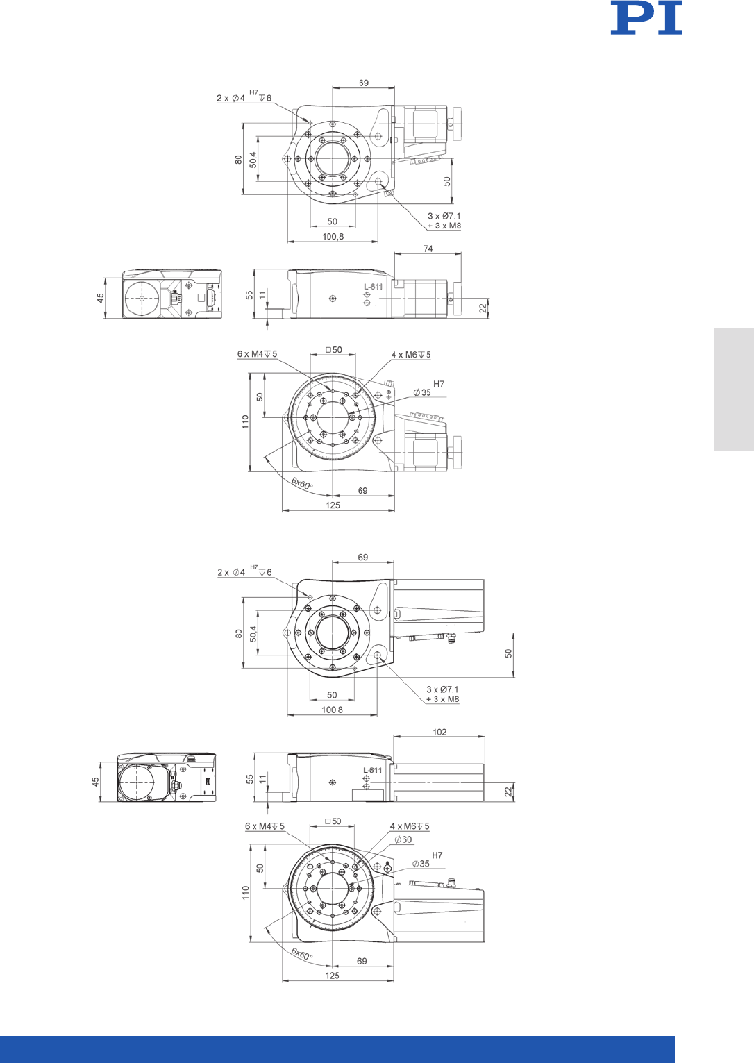
MOTION | POSITIONING
177
L-611 with stepper motor, dimensions in mm
L-611 with ActiveDrive, DC, and BLDC motor,
dimensions in mm
Rotation Stages
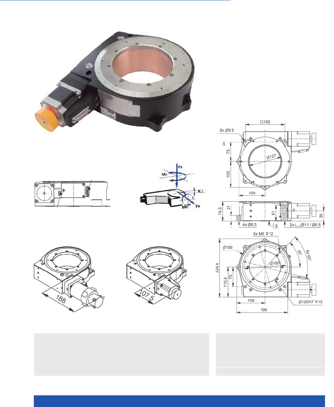
WWW.PI.WS
178
Large Aperture, High Travel Accuracy
n Unlimited travel range
n Repeatability to 0.5 µrad
n Load capacity to 50 kg
n Option: Direct position measurement
with angle measuring system
PRS-200 precision rotation stage, dimensions in mm
PRS-200 Precision Rotation Stage
>> Incremental Encoder
>> Vacuum-Compatible Versions
Technology Glossary ...................... page 290
Applications
n Medical Industry
n Metrology / Testing
n Photonics
n Precision Micro Assembly
n Sample Inspection
PRS-200 precision rotation stage,
connection for angle measuring system
PRS-200 precision rotation stage,
DC motor, dimensions in mm
Direction of the
axes and torques
fo rotation stages
PRS-200 precision rotation stage,
stepper motor, dimensions in mm

MOTION | POSITIONING
179
6449911011 6449921011 6449921111 Unit Tolerance
With DC motor With stepper motor With stepper motor
and angle measuring
system
Active axes θZθZθZ
Motion and positioning
Rotation range >360 >360 >360 °
Integrated sensor Rotary encoder Incremental angle
measuring system
Sensor signal A/B quadrature,
RS-422
– Sin/cos,
1 V peak-peak
Sensor resolution rotary encoder 20000 – – Cts./rev.
Sensor resolution angle
measuring system
– – 23600 Lines/
revolution
Design resolution 1.75 175.00 0.017 µrad
Minimum incremental motion 8.72 8.72 0.50 µrad typ.
Unidirectional repeatability 17.44 17.44 0.5 µrad typ.
Bidirectional repeatability ±175 ±175 ±5 µrad typ.
Wobble ±17.5 ±17.5 ±17.5 µrad typ.
Flatness ±1 ±1 ±1 µm typ.
Eccentricity ±2.5 ±2.5 ±2.5 µm typ.
Angular velocity 75 35 35 °/s max.
Mechanical properties
Bearing Crossed roller
bearings
Crossed roller
bearings
Crossed roller
bearings
Torque, power on 4 4 4 N·m max.
Worm gear ratio 180:1 180:1 180:1
Load capacity / axial force 500 500 500 N max.
Permissible lateral force 200 200 200 N max.
Permissible torque in θX, θY60 60 60 N·m max.
Permissible torque in θZ4 4 4 N·m max.
Drive properties
Motor type DC motor 2-phase stepper
motor
2-phase stepper
motor
Operating voltage, nominal 24 48 48 V nom.
Operating voltage, max. 48 48 48 V max.
Limit switches 2 × Hall effect 2 × Hall effect 2 × Hall effect
Miscellaneous
Operating temperature range 5 to 40 5 to 40 5 to 40 °C
Material Aluminum, black
anodized, stainless
steel, red bronze
Aluminum, black
anodized, stainless
steel, red bronze
Aluminum, black
anodized, stainless
steel, red bronze
Mass 8 8 8.7 kg ±5 %
Moved mass, unloaded 4.3 4.3 4.7 kg ±5 %
Connection Sub-D 7W2 (m)
(motor)
M23 12-pin (m)
(sensor)
Sub-D 15 (m) Sub-D 15 (m)
(motor)
HD Sub-D 26 (m)
(sensor)
Recommended controllers /
drivers
C-863 (single axis)
with C-863.AD12
line driver
C-884 (to 6 axes)
with C-863.AD12
line driver
C-885 with
C-863.20C885
(to 40 axes)
and C-863.AD12
line driver
ACS modular
controller
C-663.12 (single axis)
SMC Hydra
(double axis)
C-885 with
C-663.12C885
(up to 20 axes)
ACS modular
controller
C-663.12 (single axis)
SMC Hydra
(double axis)
C-885 with
C-663.12C885
(up to 20 axes)
ACS modular
controller
Connecting cables for motor and sensor are not in the scope of delivery and must be ordered separately.
Ask about custom designs!
Rotation Stages
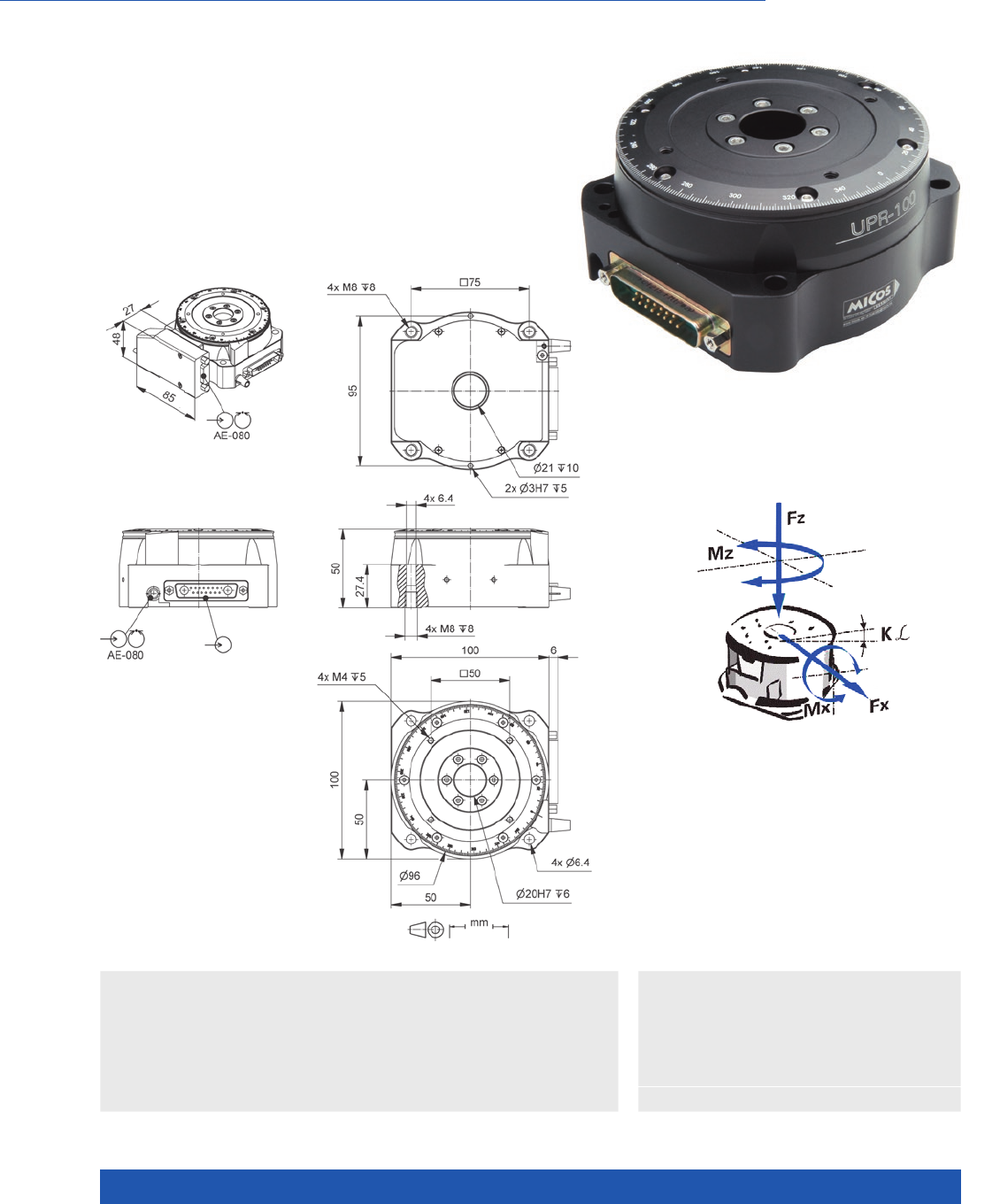
WWW.PI.WS
180
High Dynamics due to Magnetic Drive, High Stability
n Unlimited travel range
n Velocity to 360 °/s
n Repeatability to 1.4 µrad
n Clear aperture with 20 mm diameter
n Direct drive
UPR-100 ultraprecision rotation stage, dimensions in mm
UPR-100 Ultraprecision Rotation Stage
>> Incremental Encoder
>> Torque Motor
Technology Glossary ...................... page 290
Applications
n Automation
n Biotechnology
n Medical Industry
n Metrology / Testing
n Precision Micro Assembly
n Sample Inspection
n Scientific Instrumentation
n Semiconductor
Directions of the axes and torques
for rotation stages

MOTION | POSITIONING
181
680591111 Unit Tolerance
Motion and positioning
Active axes θZ
Travel range >360 °
Integrated sensor Incremental angle
measuring system
Sensor signal Sin/cos, 1 V peak-peak
Sensor resolution 15744 Lines/
revolution
Minimum incremental motion 1.4 µrad typ.
Unidirectional repeatability 1. 4 µrad typ.
Bidirectional repeatability ±1.75 µrad typ.
Flatness ±2.5 µm typ.
Eccentricity ±3.5 µm typ.
Wobble ±25 µrad typ.
Angular velocity 360 °/s max.
Reference point switch Encoder index
Mechanical properties
Bearing Crossed roller bearings
Torque, power on 0.25 N·m
Load capacity / axial force 20 N max.
Permissible lateral force 15 N max.
Permissible torque in θX, θY5 N·m max.
Drive properties
Drive type Ironless 3-phase torque motor
Intermediate circuit voltage 48 V DC max.
Nominal current, effective 1.2 A typ.
Peak current, effective 3.8 A typ.
Torque constant, effective 0.13 N·m/A typ.
Motor constant 0.04 N·m/√W typ.
Electrical time constant 0.1 ms
Resistance phase-phase 6.6 Ω typ.
Inductance phase-phase 0.7 mH typ.
Back EMF phase-phase 0.67 V/kRPM max.
Number of pole pairs 14
Miscellaneous
Operating temperature range 5 to 40 °C
MTBF 20000 h
Material Aluminum, black anodized
Mass 1.2 kg ±5 %
Moved mass 0.4 kg ±5 %
Connection Sub-D 17W2 (motor)
HD Sub-D 26 (m) (sensor)
Recommended controller SMC Hydra (double axis)
C-891 (single axis)
C-885 with C-891.10C885
(up to 20 axes)
ACS modular controller
Connecting cables for motor and sensor are not in the scope of delivery and must be ordered separately.
Ask about custom designs!
Rotation Stages
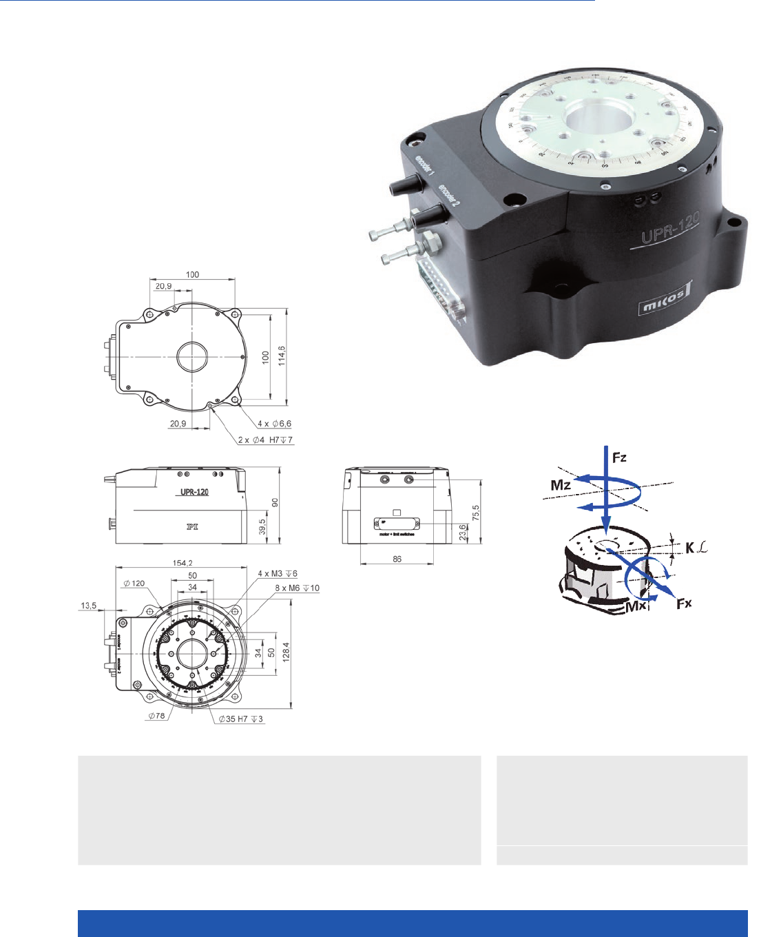
WWW.PI.WS
182
Excellent Stability and Travel Accuracy
n Unlimited travel range
n Velocity to 360 °/s
n Incremental angle measuring system
with 0.017 µrad resolution
n Clear aperture with 35 mm diameter
n Cleanroom compatible
n Direct drive
UPR-120, dimensions in mm
UPR-120 Ultraprecision Rotation Stage
Directions of the axes and torques
for rotation stages
>> Incremental Encoder
>> Torque Motor
Technology Glossary ...................... page 290
Applications
n Biotechnology
n Automation
n Medical Industry
n Metrology / Testing
n Precision Micro Assembly
n Sample Inspection
n Scientific Instrumentation
n Semiconductor

MOTION | POSITIONING
183
6808911130 Unit Tolerance
Motion and positioning
Active axes θZ
Travel range >360 °
Integrated sensor Incremental angle-measuring
system
Sensor signal Sin/cos, 1 V peak-peak
Sensor resolution 15744 Lines/
revolution
Minimum incremental motion 1.4 µrad typ.
Unidirectional repeatability 1. 4 µrad typ.
Bidirectional repeatability ±1.4 µrad typ.
Flatness ±1 µm typ.
Eccentricity ±3 µm typ.
Wobble ±25 µrad typ.
Angular velocity 360 °/s max.
Reference point switch Encoder index
Limit switches Optical
Mechanical properties
Bearing Crossed roller bearings
Torque, power on 0.5 N·m
Load capacity / axial force 200 N max.
Permissible lateral force 100 N max.
Drive properties
Drive type Iron-core 2-phase torque motor
Intermediate circuit voltage 48 V DC max.
Nominal current, effective 7. 7 A typ.
Torque constant, effective 0.26 N·m/A typ.
Resistance phase-phase 2.2 Ω typ.
Inductance phase-phase 1.17 mH typ.
Back EMF phase-phase 0.18 V·s/rad max.
Miscellaneous
Operating temperature range 5 to 40 °C
Material Aluminum, black anodized
MTBF 20000 h
Mass 6 kg ±5 %
Moved mass 0.8 kg ±5 %
Connection Sub-D 9W4 (m) (motor)
Sub-D 15 (m) (sensor)
Recommended controller SMC Hydra (double axis)
C-891 (single axis)
C-885 with C-891.10C885
(up to 20 axes)
ACS modular controller
Connecting cables for motor and sensor are not in the scope of delivery and must be ordered separately.
Ask about custom designs!
Rotation Stages
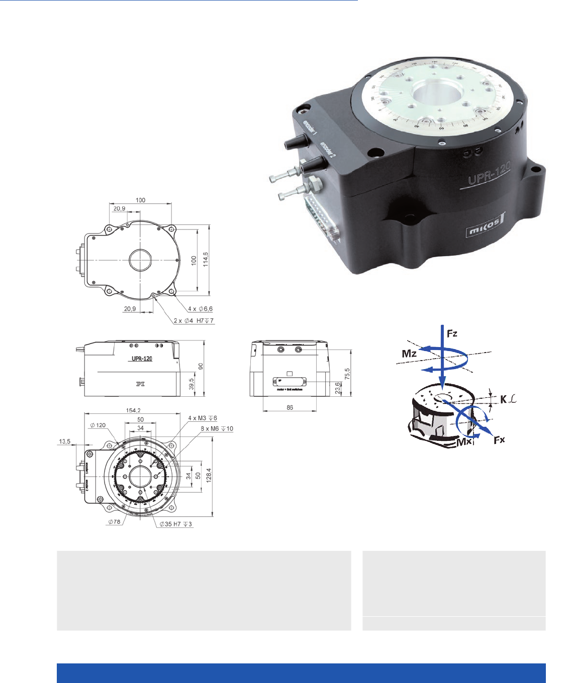
WWW.PI.WS
184
Excellent Stability and Travel Accuracy
n Unlimited travel range
n Velocity to 360 °/s
n Incremental angle measuring system
with 0.017 µrad resolution
n Clear aperture with 35 mm diameter
n Air bearings for optimized flatness
n Cleanroom compatible
n Direct drive
UPR-120, dimensions in mm
UPR-120 Air Ultraprecision
Rotation Stage with Air Bearing
Directions of the axes and torques
for rotation stages
>> Air Bearing
>> Incremental Encoder
>> Torque Motor
Technology Glossary ...................... page 290
Applications
n Biotechnology
n Automation
n Medical Industry
n Metrology / Testing
n Precision Micro Assembly
n Sample Inspection
n Scientific Instrumentation
n Semiconductor

MOTION | POSITIONING
185
6824911130 Unit Tolerance
Motion and positioning
Active axes θZ
Travel range >360 °
Integrated sensor Incremental angle-measuring
system
Sensor signal Sin/cos, 1 V peak-peak
Sensor resolution 15744 Lines/
revolution
Minimum incremental motion 0.35 µrad typ.
Unidirectional repeatability 0.7 µrad typ.
Bidirectional repeatability ±0.7 µrad typ.
Flatness ±0.05 µm typ.
Eccentricity ±0.1 µm typ.
Wobble ±1.25 µrad typ.
Angular velocity 360 °/s max.
Reference point switch Encoder index
Limit switches Optical
Mechanical properties
Bearing Air bearing
Torque, power on 0.7 N·m
Load capacity / axial force 200 N max.
Permissible lateral force 40 N max.
Drive properties
Drive type Iron-core 2-phase torque motor
Intermediate circuit voltage 48 V DC max.
Nominal current, effective 7. 7 A typ.
Torque constant, effective 0.26 N·m/A typ.
Resistance phase-phase 2.2 Ω typ.
Inductance phase-phase 1.17 mH typ.
Back EMF phase-phase 0.18 V·s/rad max.
Miscellaneous
Operating temperature range 5 to 40 °C
Material Aluminum, black anodized
MTBF 20000 h
Mass 6.5 kg ±5 %
Moved mass 1. 1 kg ±5 %
Connection Sub-D 9W4 (m) (motor)
Sub-D 15 (m) (sensor)
Recommended controller SMC Hydra (double axis)
C-891 (single axis)
C-885 with C-891.10C885
(up to 20 axes)
ACS modular controller
Connecting cables for motor and sensor are not in the scope of delivery and must be ordered separately.
Ask about custom designs!
Rotation Stages
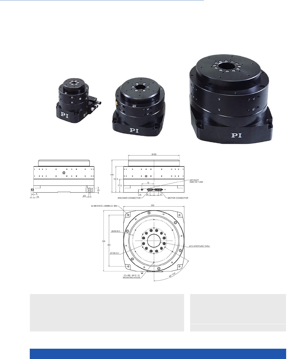
WWW.PI.WS
186
Friction-Free, Ideal for Indexing, Positioning, Scanning, Measuring Technology
n Cleanroom compatible
n Motion platform diameter from 50 mm to 300 mm
n Load capacity to 4170 N
n Eccentricity and flatness <200 nm
n Can be mounted vertically or horizontally
>> Absolute Encoder
>> Incremental Encoder
>> PIglide Air Bearing Technology
>> Torque Motor
Technology Glossary ...................... page 290
Applications
n Metrology / Testing
n Optical Alignment
n Sample Inspection
n Scanning
n Scientific Instrumentation
A-62x PIglide RM Rotation Stage
with Air Bearings
A-627.075xx, dimensions in mm

MOTION | POSITIONING
187
A-621.025 A-623.025 A-623.050 A-624.050 A-627.075 Unit Tolerance
Motion
Travel range unlimited,
>360°
unlimited,
>360°
unlimited,
>360°
unlimited,
>360°
unlimited,
>360°
Motion platform diameter 50 100 100 150 300 mm
Journal length 25 25 50 50 75 mm
Eccentricity (1) 300 175 175 100 75 nm max.
Flatness 100 75 75 50 40 nm max.
Wobble 5 3 3 2 1 µrad max.
Mechanical properties
Load capacity, axial 134 536 536 1206 4244 N max.
Load capacity, radial 57 11 5 229 344 1203 N max.
Load torque MX,Y 0.57 1.7 4.52 22.6 141.3 N·m max.
Axial stiffness 26 96 96 210 788 N/µm
Radial stiffness 8 18 35 64 204 N/µm
Moment of inertia 125 1485 1530 8790 210850 kg·mm²
Moved mass 0.4 1.2 1.4 3.2 21.5 kg
Overall mass 1. 2 3.1 4.5 8.6 50 kg
Guide type Air bearing Air bearing Air bearing Air bearing Air bearing
Drive properties
Drive type Torque
motor,
3-phase,
brushless,
ironless,
slotless
Torque
motor,
3-phase,
brushless,
ironless,
slotless
Torque
motor,
3-phase,
brushless,
ironless,
slotless
Torque
motor,
3-phase,
brushless,
ironless,
slotless
Torque
motor,
3-phase,
brushless,
ironless,
slotless
Intermediate circuit
voltage, effective
48, nominal
80, max.
48, nominal
80, max.
48, nominal
80, max.
48, nominal
80, max.
48, nominal
80, max.
V DC
Peak torque 0.21 2.1 2.1 4.71 8.46 N·m typ.
Nominal torque 0.07 0.7 0.7 1.57 2.82 N·m typ.
Force constant, effective 0.03 0.26 0.26 0.59 0.61 N·m/A typ.
Resistance phase-phase 2.7 4.2 4.2 6.7 4.5 Ω
Inductance phase-phase 0.1 0.4 0.4 0.9 0.6 mH
Back EMF phase-phase 4.1 31.8 31.8 71 74 V/kRPM max.
A-62x.xxxAx A-62x.xxxBx A-62x.xxxCx
Positioning
Integrated sensor Incremental angle measuring
system
Absolute-measuring angle
measuring system
Incremental angle measuring
system
Sensor signal Sin/cos, 1 V peak-peak BiSS-C A/B quadrature, TTL
Lines/revolution A-621: 8192
A-623: 15744
A-624: 23600
A-627: 47200
– A-621: 8192
A-623: 15744
A-624: 23600
A-627: 47200
Velocity (2) A-621: 2500 RPM max.
A-623: 1200 RPM max.
A-624: 600 RPM max.
A-627: 500 RPM max.
A-621: 2500 RPM max.
A-623: 1200 RPM max.
A-624: 600 RPM max.
A-627: 500 RPM max.
A-621: 550 RPM max. (3)
A-623: 300 RPM max. (3)
A-624: 175 RPM max. (3)
A-627: 75 RPM max. (3)
Sensor resolution A-621: 0.047 µrad (4)
A-623: 0.024 µrad (4)
A-624: 0.016 µrad (4)
A-627: 0.008 µrad (4)
A-621: 0.0015 µrad
A-623: 0.0015 µrad
A-624: 0.0015 µrad
A-627: 0.0015 µrad
A-621: 1.94 µrad (5)
A-623: 1.02 µrad (5)
A-624: 0.68 µrad (5)
A-627: 0.33 µrad (5)
Bidirectional repeatability ±4 µrad ±4 µrad ±4 µrad
Accuracy, with error
compensation (6)
±8 µrad ±8 µrad ±8 µrad
Reference point switch 1 / revolution, differential
pulse over one sensor signal
period, 1 V peak-peak
– 1 / revolution, one count
over one step of the encoder,
synchronized to output signal
Rotation Stages
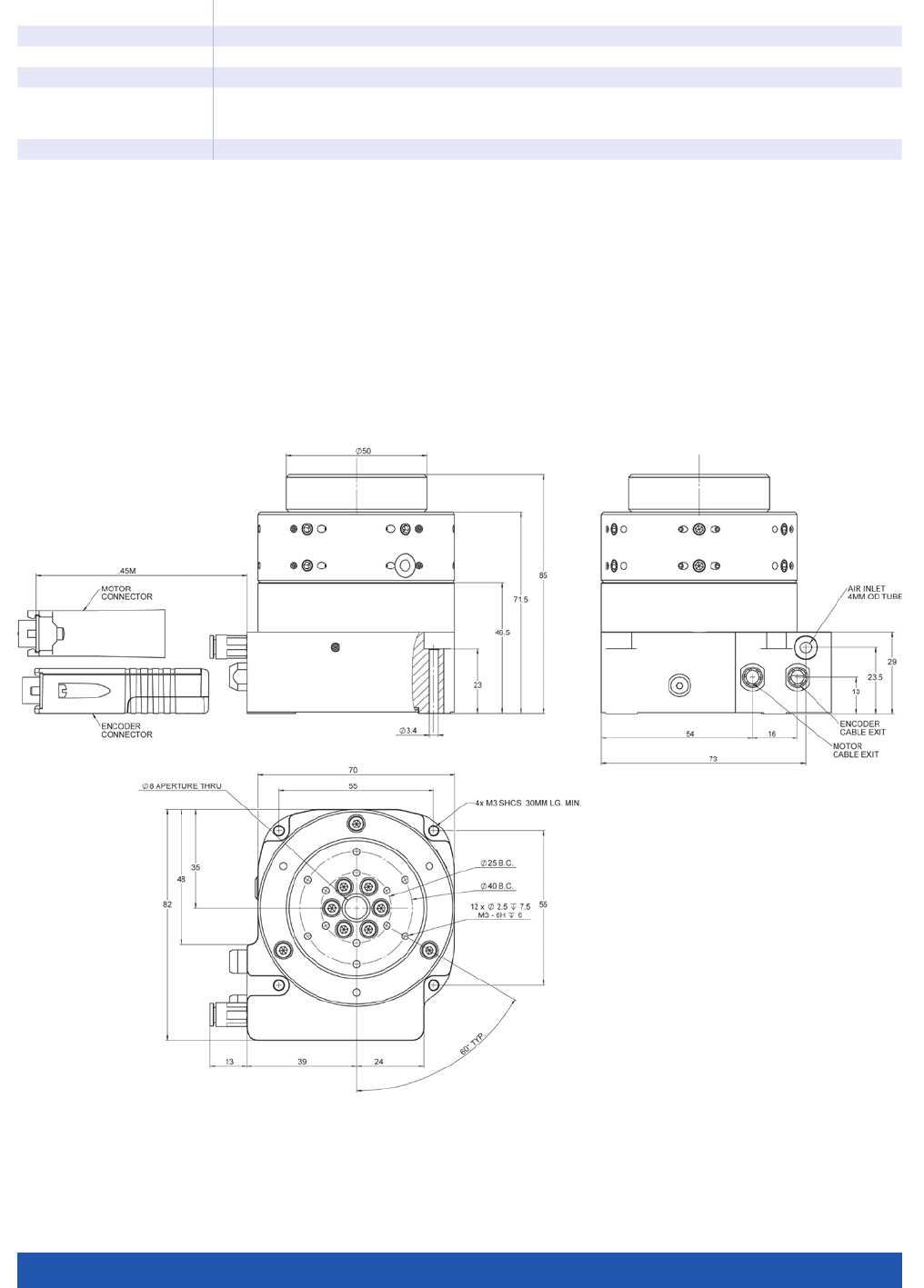
WWW.PI.WS
188
A-62x
Miscellaneous
Operating pressure (7) 75 to 85 psi (515 to 585 kPa)
Air consumption <2 SCFM (56 SLPM)
Air quality Clean (filtered to 1.0 µm or better) – ISO 8573-1 Class 1
Oil free – ISO 8573-1 Class 1
Dry (–15 °C dew point) – ISO 8573-1 Class 3
Materials (8) Hardcoat aluminum, stainless steel fasteners
(1) Dependent on the quality of the underlying surface, the payload, orientation, and forces that act on the stage from the outside. Please
contact PI for application-specific parameters. The specified values are static (no rotary motion during measuring) and without load.
(2) Can be limited by imbalance of the payload or the controller and the drive.
(3) Assumes a sampling rate of 50 MHz.
(4) Assumes 16384x interpolation. Contact PI for the use of other factors.
(5) Uses 400x interpolation. Alternative digital encoder resolutions on request. Please contact PI for a quote.
(6) The specified values are based on error compensation controlled by the controller. The stage must be ordered with a controller from PI to
reach these values. Accuracy values assume short-term duration and do not consider the long-term effects of thermal drift on the stage.
(7) To protect the stage against damage, it is recommended to connect an air pressure sensor to the Motion-Stop input of the controller.
(8) Customer-specific materials such as rust-free steel on request. Please contact PI for a quote.
A-621.025xx, dimensions in mm
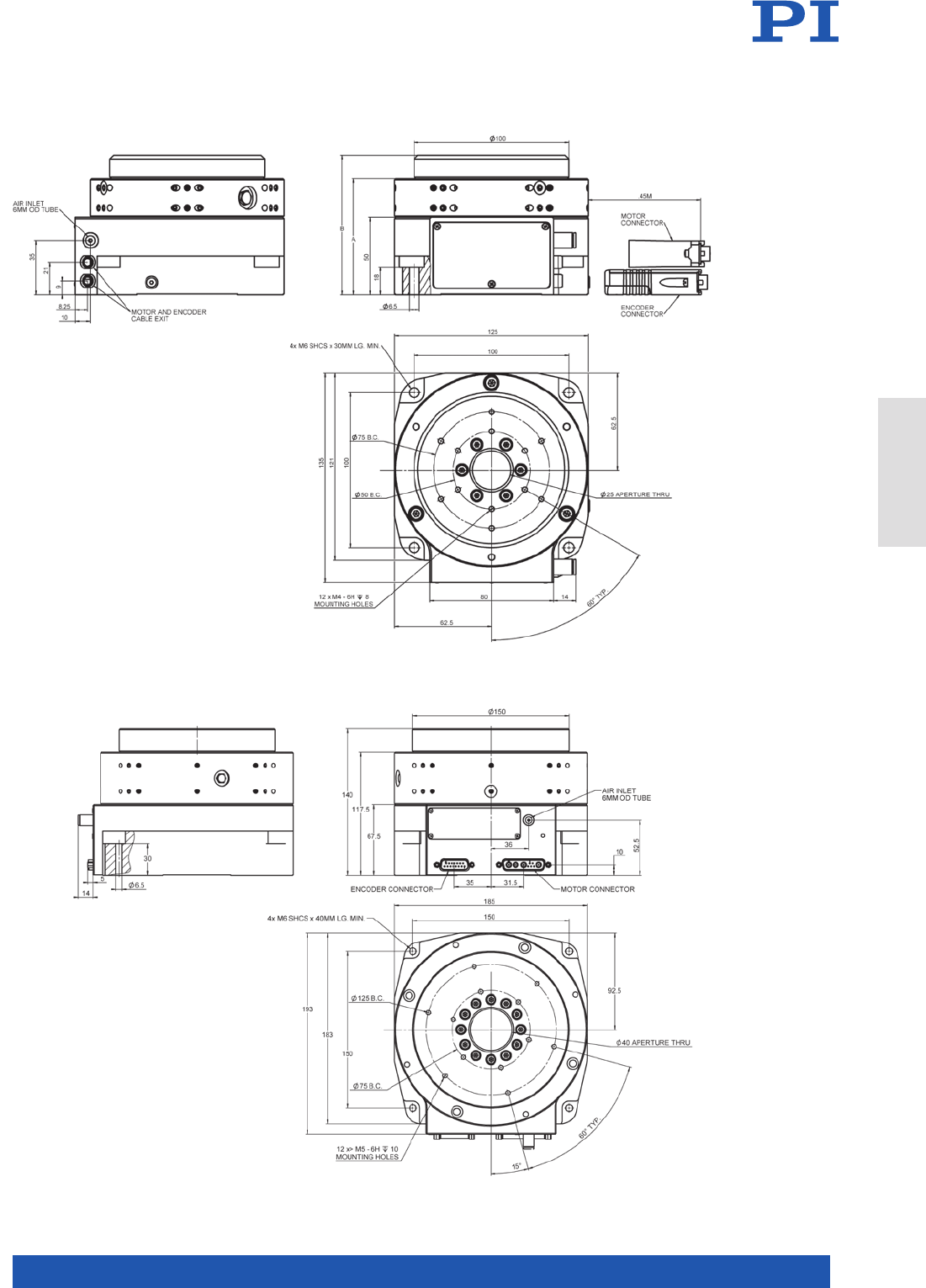
MOTION | POSITIONING
189
A-623.xxxxx, dimensions in mm
A-623.025xx: A=75 mm; B=90 mm
A-623.050xx: A=100 mm; B=115 mm
A-624.050xx, dimensions in mm
Rotation Stages
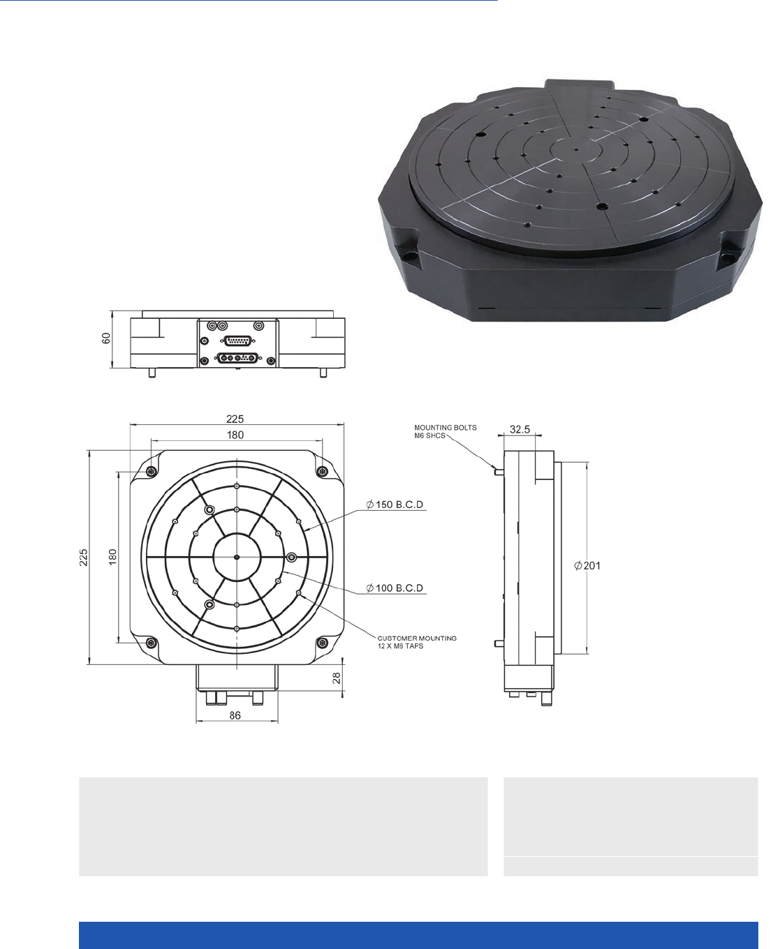
WWW.PI.WS
190
Friction-Free, Motorized
n 200 mm or 300 mm motion platform diameter
n Low profile, 60 mm
n Eccentricity and flatness <100 nm
n Option for self-locking at rest by magnetic preload
n Direct Drive
>> Absolute Encoder
>> Incremental Encoder
>> PIglide Air Bearing Technology
>> Torque Motor
Technology Glossary ...................... page 290
Applications
n Metrology / Testing
n Optical Alignment
n Sample Inspection
n Scanning
n Scientific Instrumentation
n Semiconductor
A-63x PIglide RL Low-Profile
Rotation Stage with Air Bearing
A-635.x100 , dimensions in mm
Drawing for A-637.x100
available on www.pi.ws

MOTION | POSITIONING
191
A-635 A-637 Unit Tolerance
Motion
Travel range unlimited,
>360°
unlimited,
>360°
Motion platform diameter 200 300 mm
Eccentricity (1) 100 100 nm max.
Flatness (1) 50 50 nm max.
Wobble (1) 2 1 µrad max.
Mechanical properties
Load capacity, axial (2) 200 500 N max.
Load capacity, radial (2) 50 200 N max.
Load torque, MX,Y (2) 510 N·m max.
Moment of inertia 25820 72000 kg·mm²
Moved mass 4.2 6.4 kg
Overall mass 7. 5 14 kg
Guide type Air bearing, magnetic preload Air bearing, magnetic preload
A-63x.A100 A-63x.B100
Positioning
Integrated sensor Incremental angle-measuring system Absolute angle-measuring system
Sensor signal Sin/cos, 1 V peak-peak BiSS-C
Lines/revolution A-635: 31488
A-637: 47200
–
Velocity (3) A-635: 500 rpm max.
A-637: 500 rpm max.
A-635: 500 rpm max.
A-637: 500 rpm max.
Sensor resolution A-635: 0.05 µrad (4)
A-637: 0.03 µrad (4)
A-635: 0.0015 µrad
A-637: 0.0015 µrad
Bidirectional repeatability ±2 µrad ±2 µrad
Accuracy, with error
compensation (5)
±6 µrad ±6 µrad
Reference point switch 1 / revolution, differential pulse over one
sensor signal period, 1 V peak-peak
–
A-63x Unit Tolerance
Drive properties
Drive type Torque motor, 3-phase, brushless, ironless, slotless
Intermediate circuit voltage,
effective
48, nominal
80, max.
V DC
Peak torque 9 N·m typ.
Nominal torque 3 N·m typ.
Torque constant, effective 0.66 N·m/A typ.
Resistance phase-phase 4.5 Ω
Inductance phase-phase 0.6 mH
Back EMF phase-phase 80 V/kRPM max.
A-63x
Miscellaneous
Operating pressure (6) 75 to 85 psi (515 to 585 kPa)
Air consumption <2 SCFM (56 SLPM)
Air quality Clean (filtered to 1.0 µm or better) – ISO 8573-1 Class 1
Oil free – ISO 8573-1 Class 1
Dry (–15 °C dew point) – ISO 8573-1 Class 3
Materials Hardcoat aluminum, stainless steel fasteners
(1) Dependent on the quality of the underlying surface, the payload, orientation, and forces that act on the stage from the outside.
Please contact PI for application-specific parameters. The specified values are static (no rotary motion during measuring) and without load.
(2) The loads listed assume a supply pressure of 550 kPa (80 psi). Please contact PI if other pressures are required.
(3) May be limited by the payload, payload imbalance, controller or drive.
(4) Assumes 4096x interpolation. Contact PI for the use of other factors.
(5) The specified values are based on error compensation controlled by the controller. The stage must be ordered with an A-8xx series controller
from PI to reach these values. Accuracy values assume short-term duration and do not consider the long-term effects of thermal drift on the stage.
(6) To protect the stage against damage, it is recommended to connect an air pressure sensor to the Motion-Stop input of the controller.
Rotation Stages
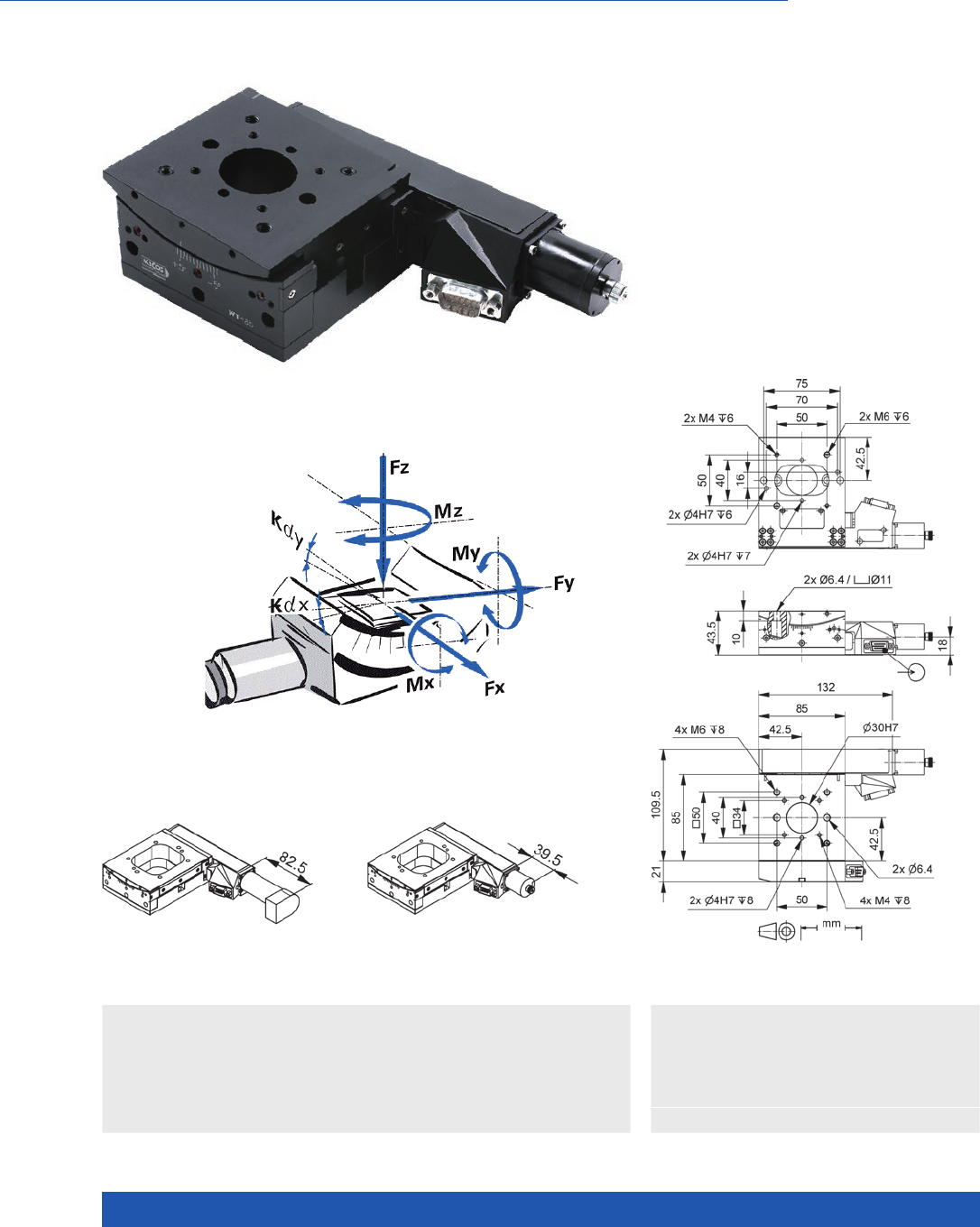
WWW.PI.WS
192
Compact, Clear Aperture
WT-85 Motorized Precision Goniometer
n Rotation range 10°
n Repeatability to 8.7 µrad
n Load capacity to 2 kg
n Option: Direct position measurement
with angle measuring system
n Combination with WT-100 with
common pivot point
>> Direct Metrology
>> Vacuum-Compatible Version
Technology Glossary ...................... page 290
WT-85 goniometer stage, dimensions in mm
Applications
n Sample Inspection
n Precision Micro Assembly
n Metrology / Testing
n Photonics
n Optical Alignment
n Scientific Instrumentation
WT-85 goniometer stage, DC motor,
dimensions in mm
WT-85 goniometer stage, stepper motor,
dimensions in mm
Direction of the axes and
torques for goniometer stages

MOTION | POSITIONING
193
65409100 65409101 65409200-0000 65409201-0001 Unit Tolerance
DC motor with
rotary encoder DC motor
with angle
measuring
system and
rotary encoder
Stepper motor Stepper motor
and angle
measuring
system
Active axes θXθXθXθX
Motion and positioning
Rotation range 10 10 10 10 °
Integrated sensor Rotary encoder Incremental
angle measur-
ing system
Rotary encoder
– Incremental
angle measur-
ing system
Sensor signal rotary
encoder AB quadrature,
RS-422 AB quadrature,
RS-422 – –
Sensor signal angle
measuring system Sin/cos, 1 V
peak-peak –Sin/cos, 1 V
peak-peak
Sensor signal periods angle
measuring system –2 11 –2 11 µrad
Sensor resolution rotary
encoder 2000 2000 – – Counts/
rev.
Design resolution 4.65 2.11 46.5 (full step) 2.11 µrad
Minimum incremental motion 1 7. 5 21 7. 5 2 µrad typ.
Unidirectional repeatability 69.8 8.7 69.8 8.7 µrad typ.
Bidirectional repeatability ±69.8 ±8.7 ±69.8 ±8.7 µrad typ.
Wobble ±125 ±125 ±125 ±125 µrad typ.
Angular velocity 15 15 7 7 °/s max.
Limit switches 2 × mechanical 2 × mechanical 2 × mechanical 2 × mechanical
Mechanical properties
Drive screw type Ball screw Ball screw Ball screw Ball screw
Drive screw pitch 1 1 1 1 mm
Guide type Ball bearings Ball bearings Ball bearings Ball bearings
Gear ratio 675:1 675:1 675:1 675:1
Load capacity 20 20 20 20 N max.
Torque Mx, power on 0.75 0.75 0.75 0.75 N·m max.
Permissible lateral force 15 15 15 15 N max.
Permissible torque in θy, θz4 4 4 4 N·m max.
Drive properties
Motor type DC motor DC motor 2-phase
stepper motor 2-phase
stepper motor
Operating voltage, nominal 24 24 24 24 V nom.
Operating voltage, max. 48 48 48 48 V max.
Step resolution – – 200 200 Full
steps/rev.
Miscellaneous
Operating temperature range 5 to 40 5 to 40 5 to 40 5 to 40 °C
Material Aluminum,
black anodized Aluminum,
black anodized Aluminum,
black anodized Aluminum,
black anodized
Mass 0.9 0.9 0.9 1.1 kg ±5 %
Connection HD Sub-D 15
(m)
(motor/sensor)
HD Sub-D 15
(m) (motor)
Sub-D 9 (m)
(sensor)
HD Sub-D 15
(m) HD Sub-D 15
(m) (motor)
Sub-D 9 (m)
(sensor)
Recommended controllers /
drivers C-863
(single axis)
C-884
(up to 6 axes)
C-885 with
C-863.20C885
(to 40 axes)
ACS modular
controller
C-863
(single axis)
C-884
(up to 6 axes)
C-885 with
C-863.20C885
(to 40 axes)
ACS modular
controller
C-663.12
(single axis)
SMC Hydra
(double axis)
C-885 with
C-663.12C885
(up to 20 axes)
ACS modular
controller
C-663.12
(single axis)
SMC Hydra
(double axis)
C-885 with
C-663.12C885
(up to 20 axes)
ACS modular
controller
Connecting cables for motor and sensor are not in the scope of delivery and must be ordered separately.
Ask about custom designs!
Rotation Stages
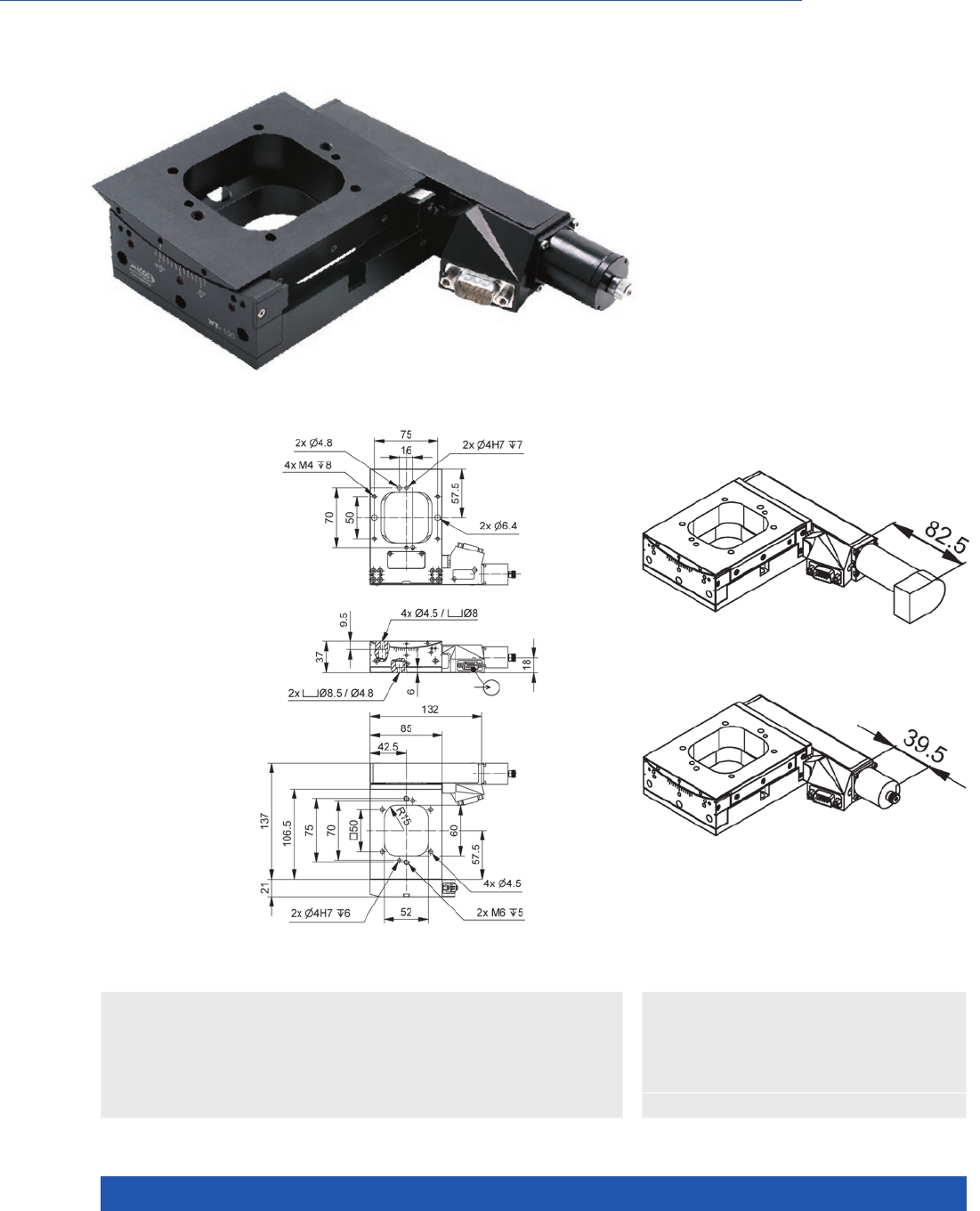
WWW.PI.WS
194
Compact, with Large Aperture
WT-100 Motorized Precision Goniometer
n Rotation range 10°
n Repeatability to 8.7 µrad
n Load capacity to 2 kg
n Option: Direct position
measurement with angle
measuring system
n Combination with WT-85
with common pivot point
>> Direct Metrology
>> Vacuum-Compatible Version
Technology Glossary ...................... page 290
Applications
n Sample Inspection
n Precision Micro Assembly
n Metrology / Testing
n Photonics
n Optical Alignment
n Scientific Instrumentation
WT-100 goniometer stage, DC motor,
dimensions in mm
WT-100 goniometer stage,
stepper motor,dimensions in mm
WT-100 goniometer stage,
dimensions in mm

MOTION | POSITIONING
195
65419100 65419101 65419200-0000 65419201-0001 Unit Tolerance
DC motor with
rotary encoder
DC motor
with angle
measuring
system and
rotary encoder
With stepper
motor
Stepper motor
and angle
measuring
system
Active axes θXθXθXθX
Motion and positioning
Rotation range 10 10 10 10 °
Integrated sensor Rotary encoder Incremental
angle measur-
ing system
Rotary encoder
– Incremental
angle measur-
ing system
Sensor signal rotary encoder AB quadrature,
RS-422
AB quadrature,
RS-422
– –
Sensor signal angle measuring
system
–Sin/cos, 1 V
peak-peak
–Sin/cos, 1 V
peak-peak
Sensor signal periods angle
measuring system
–157 –157 µrad
Sensor resolution rotary
encoder
2000 2000 – Cts./rev.
Design resolution 3.49 1.57 34.9 1.57 µrad
Minimum incremental motion 1 7. 5 8.7 1 7. 5 8.7 µrad typ.
Unidirectional repeatability 70 8.7 70 8.7 µrad typ.
Bidirectional repeatability ±70 ±8.7 ±70 ±8.7 µrad typ.
Wobble ±125 ±125 ±125 ±125 µrad typ.
Angular velocity 15 15 7 7 °/s max.
Limit switches 2 × mechanical 2 × mechanical 2 × mechanical 2 × mechanical
Mechanical properties
Drive screw type Ball screw Ball screw Ball screw Ball screw
Drive screw pitch 1 1 1 1 mm
Guide type Ball bearings Ball bearings Ball bearings Ball bearings
Gear ratio 900:1 900:1 900:1 900:1
Load capacity 20 20 20 20 N max.
Permissible lateral force 15 15 15 15 N max.
Permissible torque in θY
, θZ4 4 4 4 N·m max.
Drive properties
Motor type DC motor DC motor 2-phase
stepper motor
2-phase
stepper motor
Operating voltage, nominal 24 24 24 24 V nom.
Operating voltage, max. 48 48 48 48 V max.
Step resolution – – 200 200 Full steps/
rev.
Miscellaneous
Operating temperature range 5 to 40 5 to 40 5 to 40 5 to 40 °C
Material Aluminum,
black anodized,
steel
Aluminum,
black anodized,
steel
Aluminum,
black anodized,
steel
Aluminum,
black anodized,
steel
Mass 0.9 0.9 0.9 0.9 kg ±5 %
Connection HD Sub-D 15
(m)
HD Sub-D 15
(m) (motor)
Sub-D 9 (m)
(sensor)
HD Sub-D 15
(m) (motor)
HD Sub-D 15
(m) (motor
Sub-D 9 (m)
(sensor)
Recommended controllers /
drivers
C-863
(single axis)
C-884
(up to 6 axes)
C-885 with
C-863.20C885
(to 40 axes)
ACS modular
controller
C-863
(single axis)
C-884
(up to 6 axes)
C-885 with
C-863.20C885
(to 40 axes)
ACS modular
controller
C-663.12
(single axis)
SMC Hydra
(double axis)
C-885 with
C-663.12C885
(up to 20 axes)
ACS modular
controller
C-663.12
(single axis)
SMC Hydra
(double axis)
C-885 with
C-663.12C885
(up to 20 axes)
ACS modular
controller
Connecting cables for motor and sensor are not in the scope of delivery and must be ordered separately.
Ask about custom designs!
Rotation Stages
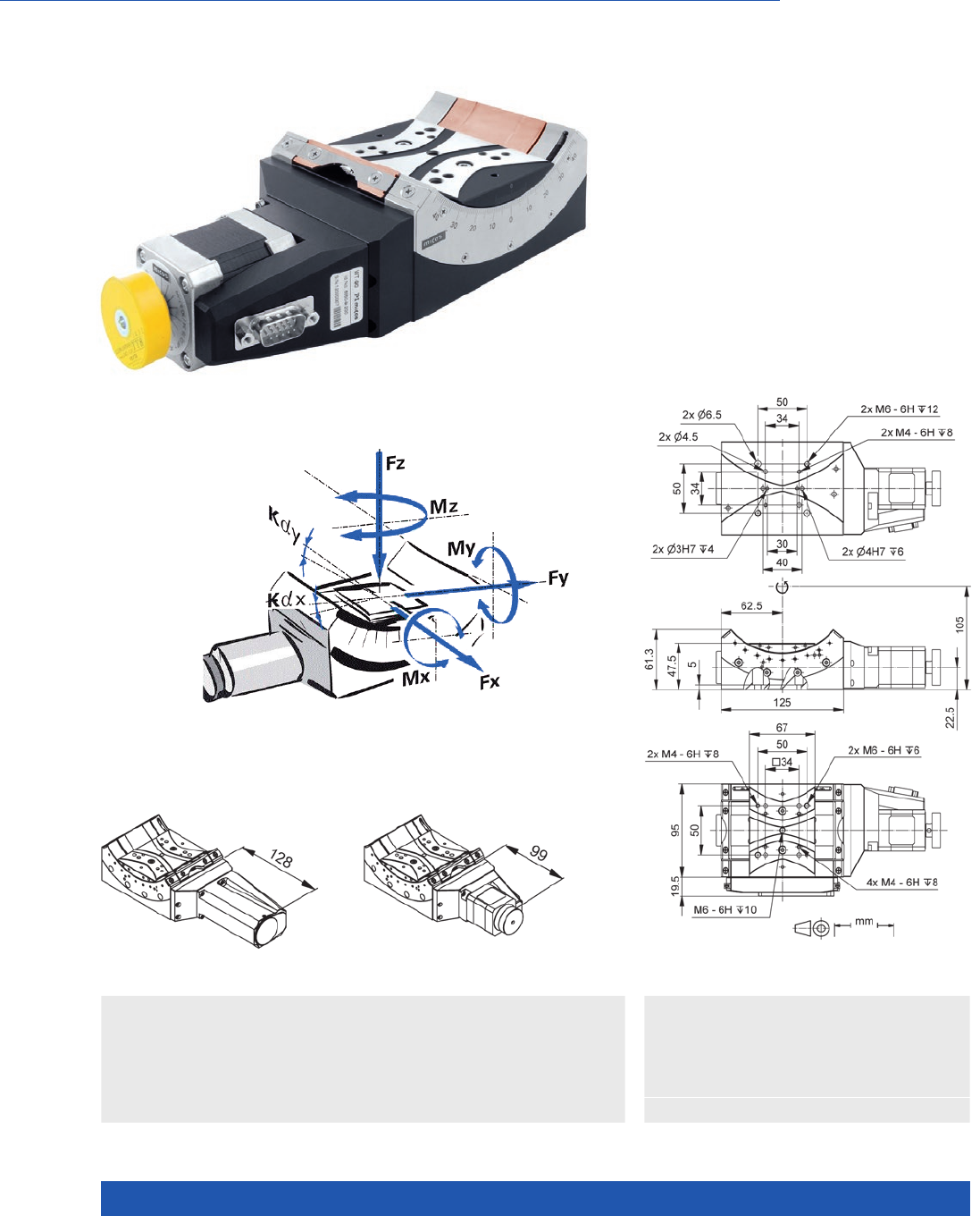
WWW.PI.WS
196
Long Travel Range
WT-90 Motorized Precision Goniometer
n Rotation range 90°
n Repeatability to 2.7 µrad
n Load capacity to 8 kg
n Option: Direct position measurement
with angle measuring system
n Combination with WT-120 with
common pivot point
>> Direct Metrology
>> Vacuum-Compatible Version
Technology Glossary ...................... page 290
Applications
n Sample Inspection
n Precision Micro Assembly
n Metrology / Testing
n Photonics
n Optical Alignment
n Scientific Instrumentation
WT-90 goniometer stage, dimensions in mm
WT-90 goniometer stage, DC motor,
dimensions in mm
WT-90 goniometer stage, stepper motor,
dimensions in mm
Direction of the axes and torques
for goniometer stages

MOTION | POSITIONING
197
65509100 65509200 65509201 Unit Tolerance
With DC motor With stepper motor With stepper motor
and angle measuring
system
Active axes θXθXθX
Motion and positioning
Rotation range 90 90 90 °
Integrated sensor Rotary encoder – Incremental angle
measuring system
Sensor signal rotary encoder AB quadrature,
RS-422
– –
Sensor signal angle
measuring system
–Sin/cos, 1 V peak-peak
Sensor resolution rotary
encoder
20000 – –
Sensor signal periods angle
measuring system
– – 269.3 µrad
Design resolution 1.047 105 2.69 µrad
Minimum incremental motion 52.4 4.8 2.7 µrad typ.
Unidirectional repeatability 87 9.6 1 7. 5 µrad typ.
Bidirectional repeatability ±350 ±175 ±17.5 µrad typ.
Wobble ±125 ±125 ±125 µrad typ.
Angular velocity 15 10 10 °/s max.
Limit switches 2 × mechanical 2 × mechanical 2 × mechanical
Mechanical properties
Guide type Ball bearings Ball bearings Ball bearings
Drive screw type Worm gear Worm gear Worm gear
Drive screw pitch mm
Worm gear ratio 300:1 300:1 300:1
Torque, power on 2.5 2.5 2.5 N·m max.
Holding torque, power off 2.5 2.5 2.5 N·m max.
Load capacity 80 80 80 N max.
Permissible lateral force 50 50 50 N max.
Permissible torque in θY
, θZ12 12 12 N·m max.
Drive properties
Motor type DC motor 2-phase stepper
motor
2-phase stepper
motor
Step resolution – 200 200 Full steps/
rev.
Miscellaneous
Operating temperature range 5 to 40 5 to 40 5 to 40 °C
Material Aluminum, black
anodized, stainless
steel, red bronze
Aluminum, black
anodized, stainless
steel, red bronze
Aluminum, black
anodized, stainless
steel, red bronze
Mass 2.8 2.8 3 kg ±5 %
Connection Sub-D 15 (m) HD Sub-D 15 (m) HD Sub-D 15 (m)
(motor)
Sub-D 9 (m) (sensor)
Recommended controllers /
drivers
C-863 (single axis)
C-884 (up to 6 axes)
C-885 with
C-863.20C885
(to 40 axes)
ACS modular
controller
C-663.12 (single axis)
SMC Hydra
(double axis)
C-885 with
C-663.12C885
(up to 20 axes)
ACS modular
controller
C-663.12 (single axis)
SMC Hydra
(double axis)
C-885 with
C-663.12C885
(up to 20 axes)
ACS modular
controller
Connecting cables for motor and sensor are not in the scope of delivery and must be ordered separately.
Ask about custom designs!
Rotation Stages
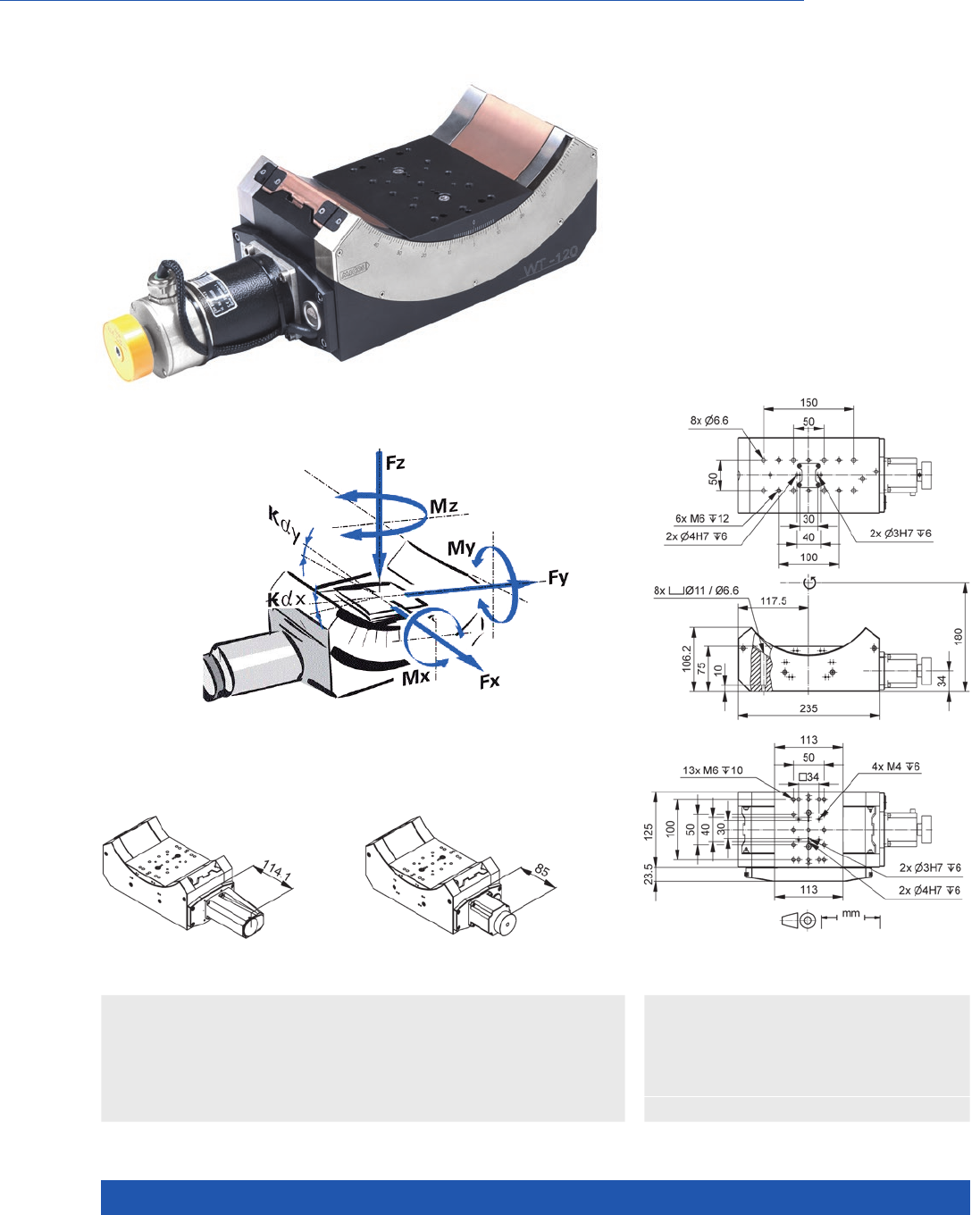
WWW.PI.WS
198
Long Travel Range, High Loads
WT-120 Motorized Precision Goniometer
n Rotation range 90°
n Repeatability to 17.5 µrad
n Load capacity to 20 kg
n Option: Direct position measurement
with angle measuring system
n Combination with WT-90 with
common pivot point
>> Direct Metrology
>> Vacuum-Compatible Version
Technology Glossary ...................... page 290
Applications
n Sample Inspection
n Precision Micro Assembly
n Metrology / Testing
n Photonics
n Optical Alignment
n Scientific Instrumentation
WT-120 goniometer stage, dimensions in mm
WT-120 goniometer stage,
DC motor, dimensions in mm
WT-120 goniometer stage,
stepper motor, dimensions in mm
Direction of the axes and torques
for goniometer stages

MOTION | POSITIONING
199
65609110 65609200 65609211 Unit Tolerance
With DC motor With stepper motor With stepper motor
and angle measuring
system
Active axes θXθXθX
Motion and positioning
Rotation range 90 90 90 °
Integrated sensor Rotary encoder – Incremental angle
measuring system
Sensor signal rotary
encoder
AB quadrature,
RS-422
– –
Sensor signal angle
measuring system
– Sin/cos,
1 V peak-peak
Sensor resolution rotary
encoder
20000 – –
Sensor signal periods angle
measuring system
––150 µrad
Design resolution 1.745 174.5 1.5 µrad
Minimum incremental motion 69.8 69.8 1 7. 5 µrad typ.
Unidirectional repeatability 87 87 1 7. 5 µrad typ.
Bidirectional repeatability ±350 ±350 ±17.5 µrad typ.
Wobble ±125 ±125 ±125 µrad typ.
Angular velocity 30 25 25 °/s max.
Limit switches 2 × mechanical 2 × mechanical 2 × mechanical
Mechanical properties
Guide type Ball bearings Ball bearings Ball bearings
Drive screw type Worm gear Worm gear Worm gear
Drive screw pitch mm
Worm gear ratio 180:1 180:1 180:1
Torque, power on 8 8 8 N·m max.
Load capacity 200 200 200 N max.
Permissible lateral force 90 90 90 N max.
Permissible torque in θY
, θZ25 25 25 N·m max.
Drive properties
Motor type DC motor 2-phase stepper
motor
2-phase stepper
motor
Step resolution – 200 200 Full steps/
rev.
Miscellaneous
Operating temperature range 5 to 40 5 to 40 5 to 40 °C
Material Aluminum, black
anodized, stainless
steel, red bronze
Aluminum, black
anodized, stainless
steel, red bronze
Aluminum, black
anodized, stainless
steel, red bronze
Mass 11. 5 11. 5 11. 5 kg ±5 %
Connection Sub-D 15 (m) LEMO ERA.3S.316
16-pin
LEMO ERA.3S.316
16-pin (motor)
Sub-D 9 (m) (sensor)
Recommended controllers /
drivers
C-863 (single axis)
with C-863.AD12
line driver
C-884 (to 6 axes)
with C-863.AD12
line driver
C-885 with
C-863.20C885
(to 40 axes)
and C-863.AD12
line driver
ACS modular
controller
C-663.12 (single axis)
SMC Hydra
(double axis)
C-885 with
C-663.12C885
(up to 20 axes)
ACS modular
controller
C-663.12 (single axis)
SMC Hydra
(double axis)
C-885 with
C-663.12C885
(up to 20 axes)
ACS modular
controller
Connecting cables for motor and sensor are not in the scope of delivery and must be ordered separately.
Ask about custom designs!
Rotation Stages
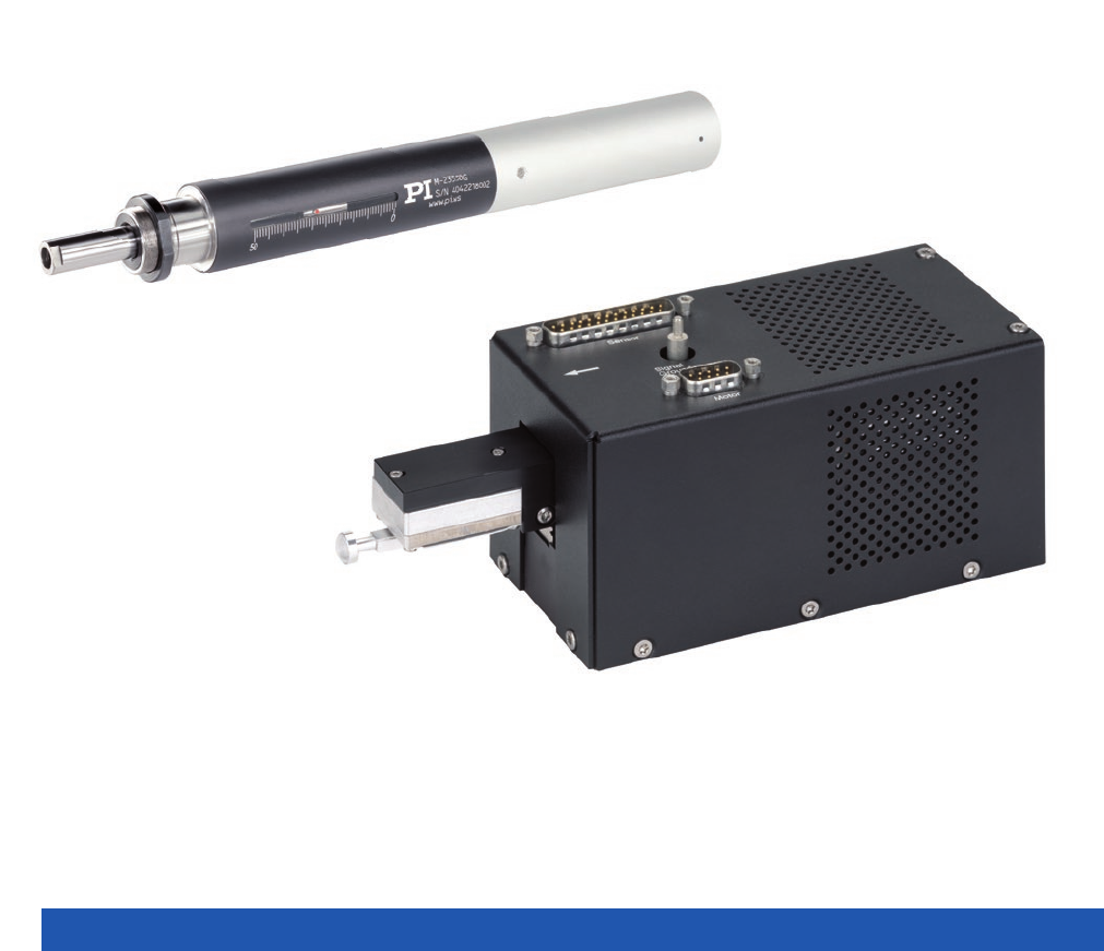
WWW.PI.WS
200
Linear Actuators

MOTION | POSITIONING
201
Voice Coil Actuators ................................................................................................................................................................ 202
V-900KPIC PIMag® VC Vertical Linear Actuator .............................................................. 202
V-273 PIMag® Voice Coil Linear Actuator ....................................................................... 204
V-275 PIMag® Voice Coil Linear Actuator ....................................................................... 208
V-277 PIMag® High-Load Linear Actuator ...................................................................... 212
Screw-Drive Precision Actuators ............................................................................................................................................. 216
L-220 High-Resolution Linear Actuator .......................................................................... 216
M-227 High-Resolution Linear Actuator with DC Motor ................................................ 218
M-228 / M-229 High-Resolution Linear Actuator with Stepper Motor ............................ 220
M-230 High-Resolution Linear Actuator with DC Motor ................................................ 222
M-232 High-Resolution Linear Actuator with DC Motor ................................................ 224
High-Load Screw-Drive Actuators ........................................................................................................................................... 226
M-235 High-Resolution Linear Actuator with DC Motor ................................................ 226
L-239 High-Load Linear Actuator ................................................................................... 228
M-238 High-Load Linear Actuator with DC Motor .......................................................... 230
Linear Actuators
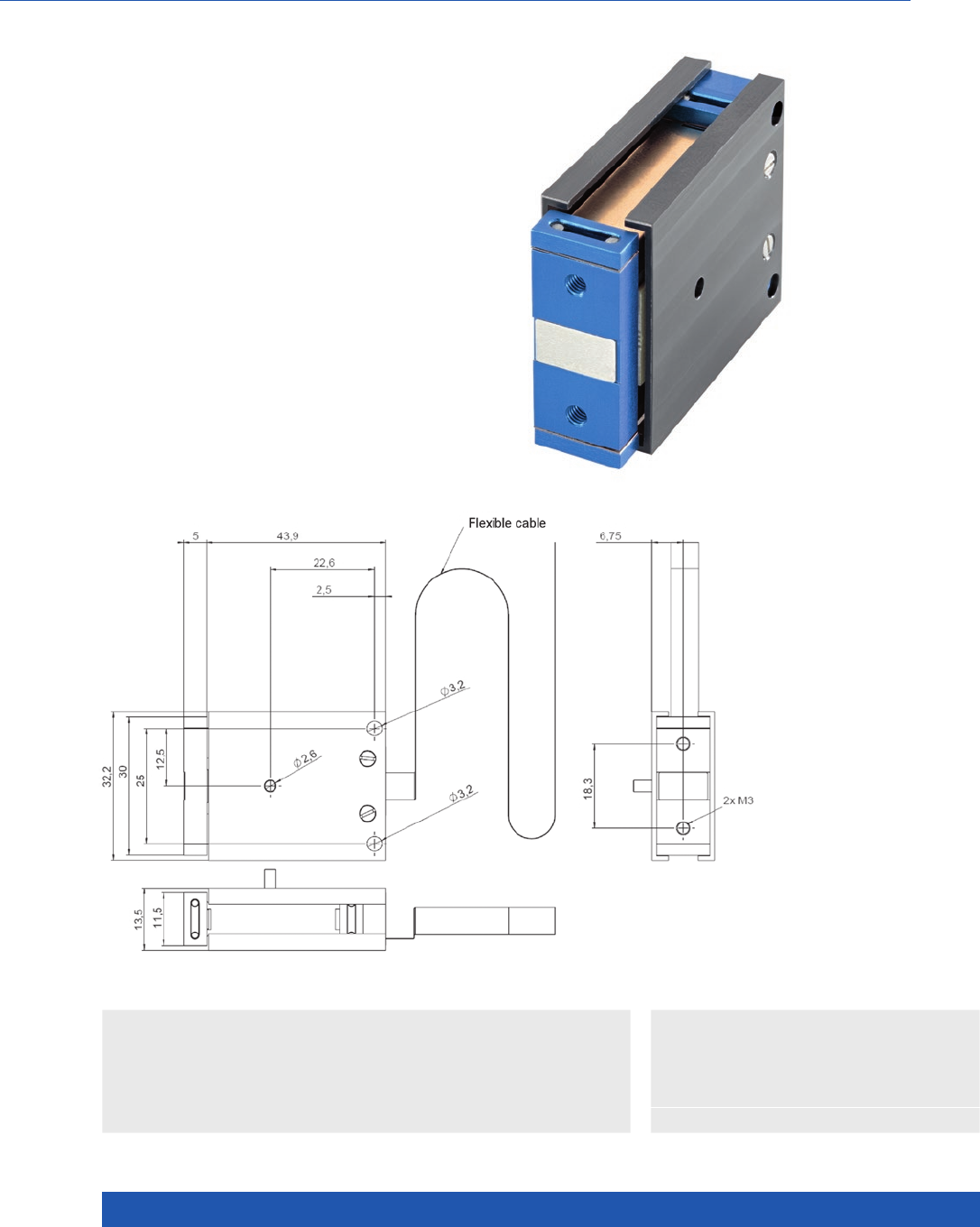
WWW.PI.WS
202
Compact with Integrated Position Sensor
V-900KPIC PIMag® VC Vertical Linear Actuator
n Travel range 1.5 mm
n High scanning frequencies, fast step-and-settle
n Integrated linear encoder with 0.1 µm resolution
n Wear-free flexure guide for long lifetime
n Compact dimensions
n OEM linear actuator
V-900KPIC, dimensions in mm
>> Flexure Guiding System
>> Incremental Encoder
>> PIMag® Voice Coil
Technology Glossary ...................... page 290
Applications
n Sample Inspection
n Precision Micro Assembly
n Electronics Manufacturing
n Metrology / Testing
n General Automation
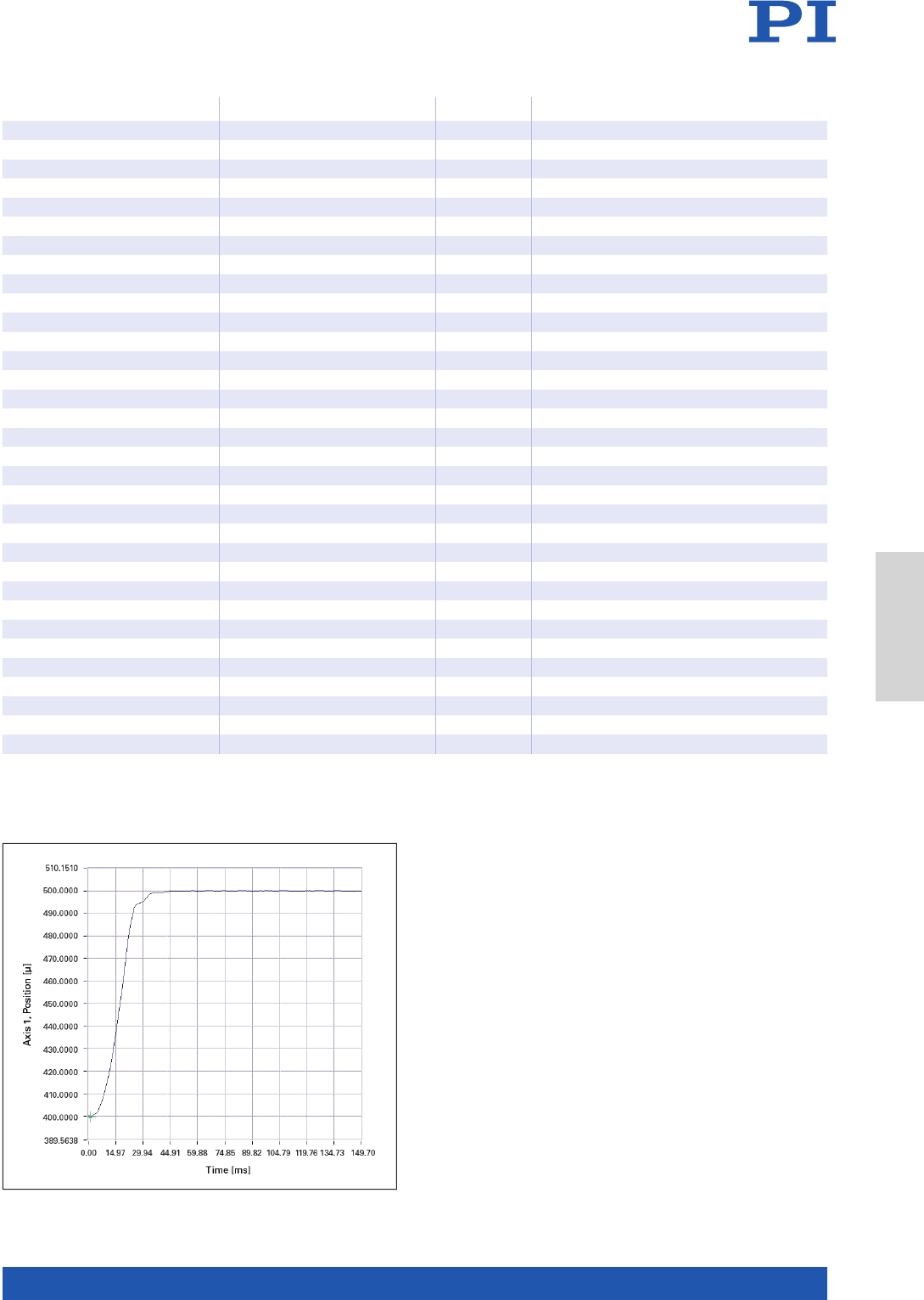
MOTION | POSITIONING
203
V-900KPIC Unit Tolerance
Active axes Z
Motion and positioning
Travel range 1.5 mm
Integrated sensor Optical linear encoder
Servo update rate 10* kHz
Resolution, open loop 10* nm typ.
Resolution, closed loop 100 nm typ.
Linearity error, closed loop ±1 % typ.
Repeatability ±500 nm typ.
Motion straightness ±5 µm ±5
Velocity, open loop 250 mm/s max.
Velocity, closed loop 45 mm/s
Mechanical properties
Moved mass 10 g typ.
Average push/pull force 0.5 N nominal
Push/pull force 0.8 N max.
Force constant 4 N/A typ.
Drive properties
Motor type PIMag® Voice Coil Drive
Magnet material NdFeB (N38SH)
Coil resistance 8.8 Ω typ.
Coil inductance 0.8 mH typ.
Average continuous current 120** mA max.
Peak current (max. 3 s) 200 mA
Miscellaneous
Operating temperature range 10 to 45 °C
Material Aluminum
Mass 40 g ±5 %
Cable length 0.2 m
Motor / sensor connection Molex 12 pins
Lifetime >108cycles min.
Recommended controller C-413 (plug adapter required)
* With C-413 controller.
** Do not exceed for continuous operation.
The settling time for a 100 µm step is approx. 50 ms.
Linear Actuators
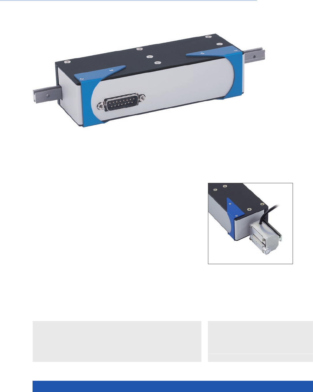
WWW.PI.WS
204
High Dynamics and Inexpensive
V-273 PIMag® Voice Coil Linear Actuator
n Travel ranges to 20 mm
n Velocity to 100 mm/s
n Integrated linear encoder, 0.01 µm resolution
n Optional force sensor with 1 mN resolution
>> Incremental Encoder
>> PIMag® Voice Coil
Technology Glossary ...................... page 290
Applications
n Sample Inspection
n Precision Micro Assembly
n Electronics Manufacturing
n Metrology / Testing
n General Automation
PIMag® Voice Coil
Voice coil drives consist of 2 essential components: A permanent magnet and
a coil, which is located in the air gap of the magnetic field. When current flows
through the coil, it moves in the magnetic field of the permanent magnet.
The direction of motion depends on the polarity. Thanks to their low weight
and friction-free drive principle, voice coil drives are particularly suitable for
applications, which require high dynamics and high velocities at limited travel
ranges. High scan frequencies and precision positioning are also possible with
these drives, because they are free of the effects of hysteresis.
Highly accurate position measuring with incremental linear encoder
Noncontact optical linear encoders measure the actual position directly at the
motion platform with the greatest accuracy so that nonlinearity, mechanical
play or elastic deformation have no influence on position measuring.
V-273.441 with force sensor

MOTION | POSITIONING
205
V-273.440
V-273.441 with force sensor
Unit Tolerance
Active axes Z
Motion and positioning
Travel range 20 mm
Integrated sensor Optical linear encoder
Sensor resolution 10 (1) nm max.
Minimum incremental motion 100 nm typ.
Linearity error, closed loop 1 % typ.
Repeatability ±0.5 µm typ.
Velocity 100 mm/s max.
Force sensor resolution (optional) 1 mN max.
Smallest force step (optional) 5 mN typ.
Mechanical properties
Bearing / guide Recirculating ball bearings
Motion straightness ±20 µm ±5 %
Moved mass without load 100 (230 with force sensor) g typ.
Drive properties
Motor type PIMag® Voice Coil Drive, moving coil
Coil resistance 16 Ω typ., at 20 °C
Coil inductance 6 mH typ., at 20 °C
Time constant 0.375 ms
Back EMF 8 V·s/m
Force constant 8 N/A typ.
Motor constant 2 N/(√W)
Current constant 0.125 A/N typ.
Average continuous current 375 (2) mA max.
Peak current (max. 3 s) 800 mA
Average push/pull force 3 N nominal
Power dissipation of the coil
with 100 % duty cycle
2.25 W
Maximum push/pull force 6 N max.
Miscellaneous
Operating temperature range 10 to 60 °C
Material Aluminum
Mass 660 (790 with force sensor) g ±5 %
Cable length 1 m
Motor / sensor connection Sub-D 15 (m) with force sensor: 2 × Sub-D 15 (m)
Lifetime >107cycles min.
Recommended controller C-413.2x
(1) With C-413 controller.
(2) Do not exceed for continuous operation.
Linear Actuators
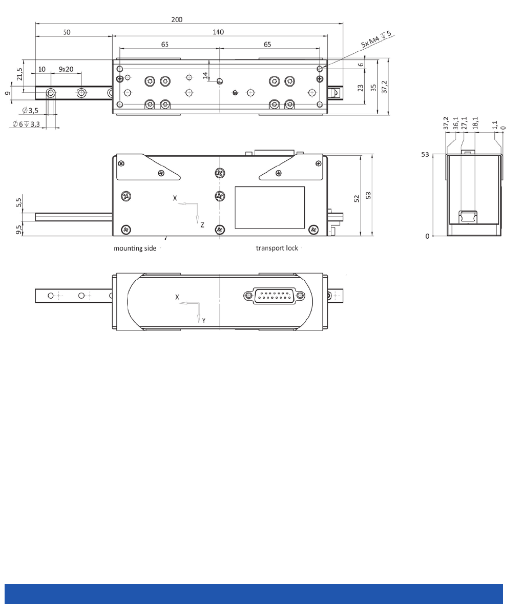
WWW.PI.WS
206
V-273.440, dimensions in mm
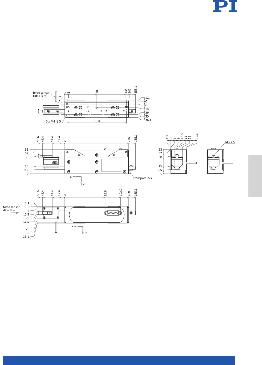
MOTION | POSITIONING
207
V-273.441, dimensions in mm
Linear Actuators
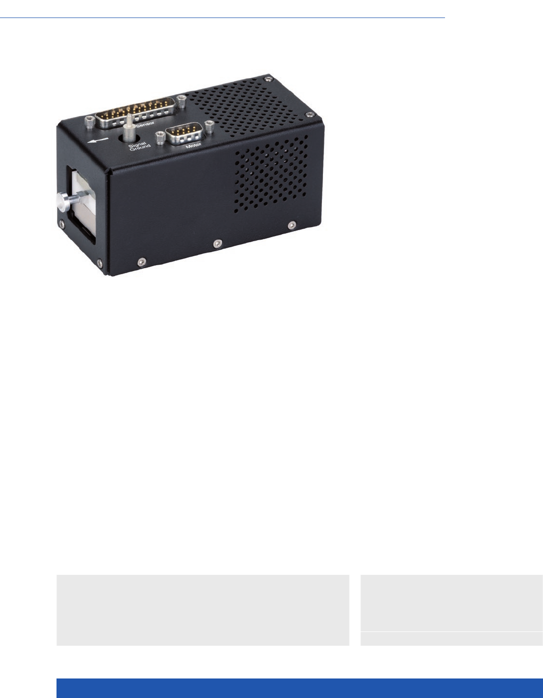
WWW.PI.WS
208
High Dynamics, with Optional Force Control
V-275 PIMag® Voice Coil Linear Actuator
n Push force up to 10 N
n Velocity to 600 mm/s
n Integrated linear encoder, 0.01 µm resolution
n Weight force compensation
n Optional force sensor with 1 mN resolution
>> Incremental Encoder
>> PIMag® Voice Coil
Technology Glossary ...................... page 290
Applications
n Sample Inspection
n Precision Micro Assembly
n Electronics Manufacturing
n Metrology / Testing
n General Automation
PIMag® Voice Coil
Voice coil drives consist of 2 essential components: A permanent magnet and
a coil, which is located in the air gap of the magnetic field. When current flows
through the coil, it moves in the magnetic field of the permanent magnet.
The direction of motion depends on the polarity. Thanks to their low weight
and friction-free drive principle, voice coil drives are particularly suitable for
applications, which require high dynamics and high velocities at limited travel
ranges. High scan frequencies and precision positioning are also possible with
these drives, because they are free of the effects of hysteresis.
Highly accurate position measuring with incremental linear encoder
Noncontact optical linear encoders measure the actual position directly at the
motion platform with the greatest accuracy so that nonlinearity, mechanical
play or elastic deformation have no influence on position measuring.

MOTION | POSITIONING
209
V-275.430
V-275.431 with force sensor
Unit Tolerance
Active axes Z
Motion and positioning
Travel range 10 mm
Integrated sensor Optical linear encoder
Sensor resolution 10 (1) nm max.
Minimum incremental motion 100 nm typ.
Linearity error, closed loop 1 % typ.
Repeatability ±0.5 µm typ.
Velocity 600 mm/s max.
Force sensor resolution (optional) 1 mN max.
Smallest force step (optional) 5 mN typ.
Mechanical properties
Bearing / guide Linear recirculating
ball bearings
Motion straightness ±5 µm ±5 %
Moved mass without load 150 g typ.
Drive properties µm
Motor type PIMag® voice coil drive,
moving coil
Coil resistance 5.7 Ω typ., at 20 °C
Coil inductance 3.75 mH typ., at 1 kHz
Time constant 0.65 ms
Back EMF 10 V·s/m
Force constant 10 N/A typ.
Motor constant 4.2 N/(√W)
Current constant 0.1 A/N typ.
Average continuous current 700 (2) mA max.
Peak current (max. 3 s) 1500 mA
Average push/pull force 7 N nominal
Power dissipation of the coil
with 100 % duty cycle
4 W
Maximum push/pull force 15 N max.
Miscellaneous
Operating temperature range 10 to 60 °C
Material Aluminum
Mass 800 g ±5 %
Cable length 3 m
Motor / sensor connection Sub-D 25 (m), with force
sensor Sub-D 9 (m)
Lifetime >107cycles min.
Recommended controller C-413.1x
(1) With C-413 controller.
(2) Do not exceed for continuous operation.
Linear Actuators
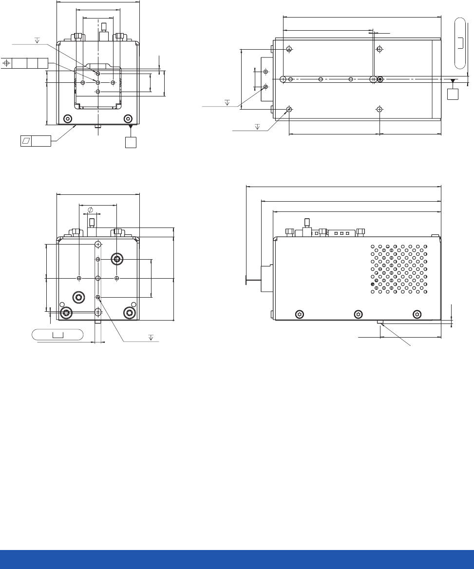
WWW.PI.WS
210
25
6
25
55
22.5
22
1
4
H7
3.5
4 x M3
5
0
28
55.5
61.6
111.5
~ 119.5 (min. pos.)
40.5
~ 2
~ 129.5 (max. pos.)
Transportsicherung
transport lock
2 x M3
5
40
60 41
59.5 1
105
4
H7
3.5
4 x M4
8
10
B
28
5 x M3
5
20
12
55
29
17 1
8
0.02
the given flatness value is also
a recommandation for the flatness
of the customer mounting interface
0.5
A B
A
V-275.430, dimensions in mm
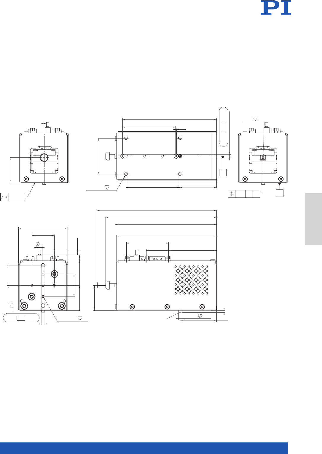
MOTION | POSITIONING
211
28
M3 thread
Signal-GND
of Probe Tip
0.02
the given flatness value is also
a recommendation for the flatness
of the customer mounting interface
M3
5
0.5
AB A
55
25
25
22 22.5
1
4
H7
3.5
4 x M3
5
6
6
0
28
55.5
61.6
40.5
111.5
~ 123.7 (min. pos.)
~ 113.5 (min. pos.)
~ 2
3.8
53.525
47
~ 133.2 (max. pos.)
28
Transportsicherung
transport lock
40
60
4
H7
3.5
41
105
59.5 1
4 x M4
8
B
V-275.431, dimensions in mm
Linear Actuators
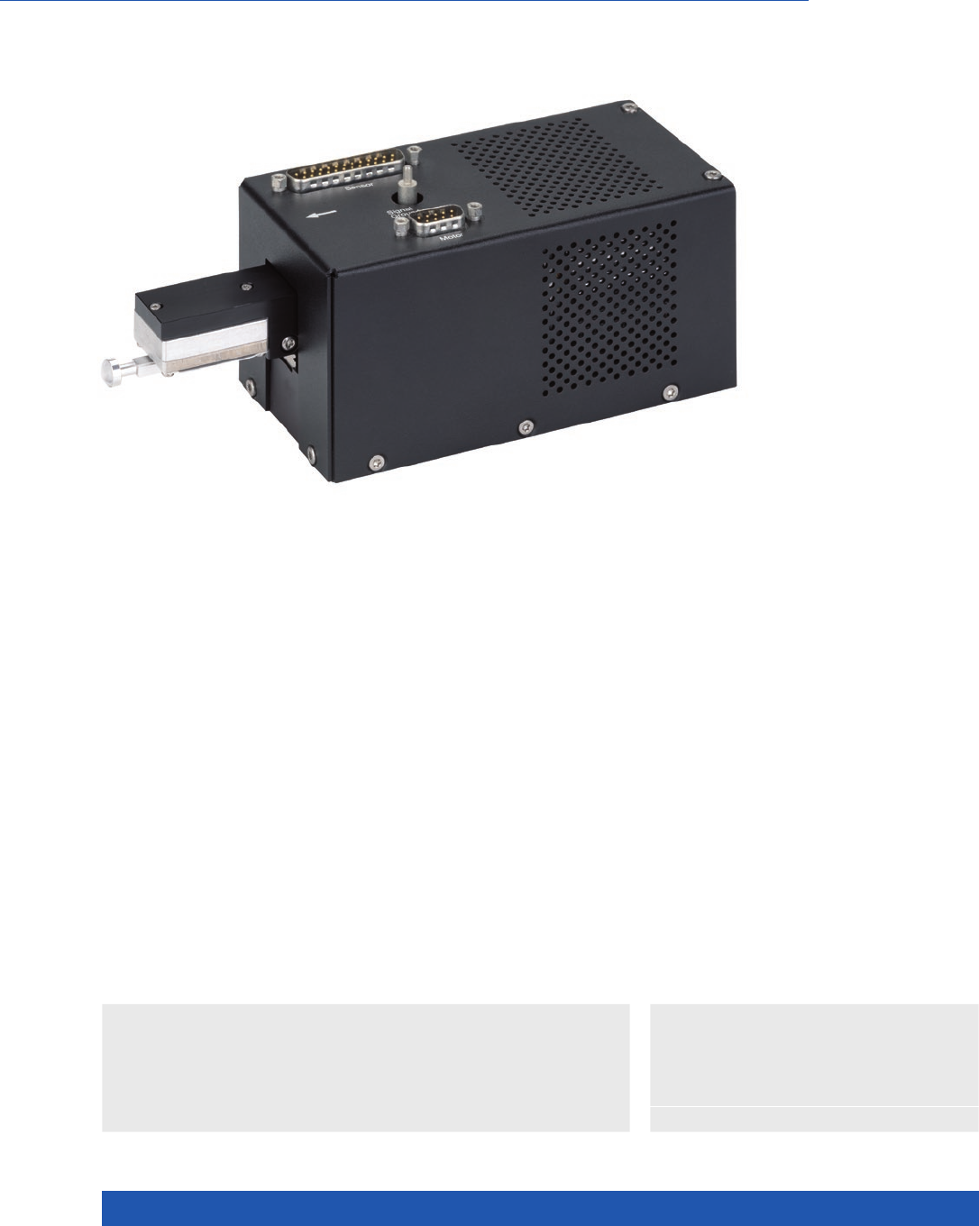
WWW.PI.WS
212
Voice Coil Drive for High Velocity
V-277 PIMag® High-Load Linear Actuator
n Force up to 20 N
n Velocity up to 750 mm/s
n Integrated linear encoder, 0.01 µm resolution
n Weight force compensation
n Optional force sensor with 1 mN resolution
>> Incremental Encoder
>> PIMag® Voice Coil
Technology Glossary ...................... page 290
Applications
n Sample Inspection
n Precision Micro Assembly
n Electronics Manufacturing
n Metrology / Testing
n General Automation
PIMag® Voice Coil
Voice coil drives consist of 2 essential components: A permanent magnet and
a coil, which is located in the air gap of the magnetic field. When current flows
through the coil, it moves in the magnetic field of the permanent magnet.
The direction of motion depends on the polarity. Thanks to their low weight
and friction-free drive principle, voice coil drives are particularly suitable for
applications, which require high dynamics and high velocities at limited travel
ranges. High scan frequencies and precision positioning are also possible with
these drives, because they are free of the effects of hysteresis.
Highly accurate position measuring with incremental linear encoder
Noncontact optical linear encoders measure the actual position directly at the
motion platform with the greatest accuracy so that nonlinearity, mechanical
play or elastic deformation have no influence on position measuring.

MOTION | POSITIONING
213
V-277.630
V-277.631 with force sensor
Unit Tolerance
Active axes Z
Motion and positioning
Travel range 15 mm
Integrated sensor Optical linear encoder
Sensor resolution 10 (1) nm max.
Minimum incremental motion 100 nm typ.
Linearity error, closed loop 1 % typ.
Repeatability ±0.5 µm typ.
Velocity 750 mm/s max.
Force sensor resolution 1 mN max.
Force resolution, closed-loop 5 mN typ.
Mechanical properties
Bearing / guide Linear recirculating ball
bearings
Motion straightness ±5 µm ±5 %
Moved mass without load 190 g typ.
Drive properties
Motor type PIMag® voice coil drive,
moving coil
Coil resistance 6.3 Ω typ., at 20 °C
Coil inductance 2.70 mH typ., at 1 kHz,
at 20 °C
Time constant 0.43 ms typ.
Back EMF 14 V·s/m
Force constant 13.5 N/A typ.
Motor constant 5.6 N/(√W)
Current constant 0.072 A/N typ.
Average continuous current 740 (2) mA max.
Peak current (max. 3 s) 1500 mA
Average push/pull force 10 N nominal
Power dissipation of the coil
with 100 % duty cycle
3.2 W
Maximum push/pull force 20 N max.
Miscellaneous
Operating temperature range 10 to 60 °C
Material Aluminum
Mass 1850 g ±5 %
Cable length 3 m
Motor / sensor connection Sub-D 25 (m), with force
sensor Sub-D 9 (m)
Lifetime >107cycles min.
Recommended controller C-413.1x
(1) With C-413 controller.
(2) Do not exceed for continuous operation.
Linear Actuators
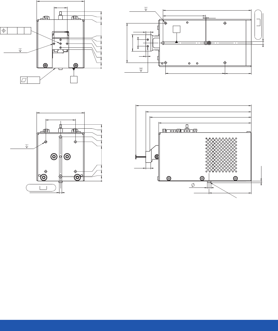
WWW.PI.WS
214
45
72
4
H7
5
4 x M4
6
0
6.5
7.5
14.5
59.5
67
79.7
85.7
73.5
5.5
64
~ 2.4
140.5
154
160 (min. pos.)
7.5
175 (max. pos.)
Transportsicherung
transport lock
5 x M3
5
20
72
0
37
31
43
28
45
46
73.5
79.7
85.7
0.5
A B
0.02
the given flatness value is also
a recommendation for the flatness
of the customer mounting interface
A
60
90 40
134
64.5 1
4
H7
5
2 x M3
5
4 x M4
12
25
10
3
7.5
B
V-277.630, dimensions in mm
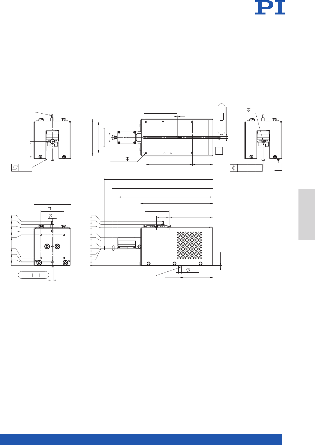
MOTION | POSITIONING
215
34
M3 thread
Signal-GND
of Probe Tip
0.02
the given flatness value is also
a recommendation for the flatness
of the customer mounting interface
4
H7
5
45
72
6
0
6.5
7.5
14.5
59.5
67
73.5
79.7
85.7
64
~ 3
140.5
~ 184.7 (min. pos.)
5.5
85
25
47
~ 196.2 (min. pos.)
~ 211.2 (max. pos.)
0
32
34
36
33
54
48
73.5
79.7
85.7
Transportsicherung
transport lock
60
90
64.5 1
40
4 x M4
12
4
H7
5
6
25
72
B
M3 5
0.5
A B A
V-277.631, dimensions in mm
Linear Actuators

WWW.PI.WS
216
Suitable for a High Number of Cycles
L-220 High-Resolution Linear Actuator
n Forces up to 125 N
n Travel ranges 13 to 77 mm
(½” to 3”)
n DC or stepper motor
n Nonrotating tip
n Vacuum-compatible versions
to 10–9 hPa on request
>> Incremental Encoder
>> Vacuum-Compatible Versions
Technology Glossary ...................... page 290
Applications
n Electronics Manufacturing
n General Automation
n Optical Alignment
n Precision Micro Assembly
n Scientific Instrumentation
n Semiconductor
L-220, dimensions in mm
Travel A B C
L-220.10SG
L-220.10DG
L-220.20SG
L-220.20DG
L-220.50SG
L-220.50DG
L-220.70SG
L-220.70DG
13
13
26
26
52
52
77
77
26
26
39
39
65
65
90
90
148,3
155,2
161,5
168,4
186,6
193,5
211,6
218,5
13
19,9
13
19,9
13
19,9
13
19,9

MOTION | POSITIONING
217
L-220.x0DG L-220.x0SG Unit Tolerance
High precision, with DC gear
motor
Stepper motor with gearhead
Motion axes X X
Motion and positioning
Travel range 13 / 26 / 52 / 77 13 / 26 / 52 / 77 mm
Integrated sensor Rotary encoder –
Sensor resolution 2048 – Cts./rev.
Design resolution 0.022 0.55 (full step) µm typ.
Minimum incremental
motion
0.1 0.1 µm typ.
Unidirectional repeatability 0.5 0.5 µm typ.
Bidirectional repeatability ±1 ±1 µm typ.
Velocity 3.5 0.8 mm/s max.
Mechanical properties
Drive screw type Ball screw Ball screw
Thread pitch 1 1 mm
Gear ratio 12493:567 387283:5103
Motor resolution – 384 (29184)* Steps/rev.
Push/pull force 125 125 N max.
Holding force 80 125 N typ.
Permissible lateral force 1 1 N max.
Drive properties
Motor type DC motor with gearhead 2-phase stepper motor
with gearhead
Operating voltage, nominal 12 12 V nom.
Operating voltage, max. 24 48 V max.
Step resolution – 24 Full steps/rev.
Limit and reference point
switches
Hall effect Hall effect
Miscellaneous
Operating temperature
range
5 to 40 5 to 40 °C
Material Stainless steel, red brass Stainless steel, red brass
Mass 0.21 / 0.23 / 0.26 /0.29 0.23 / 0.25 / 0.28 /0.32 kg ±5 %
Moved mass 0.02 / 0.02 / 0.025 / 0.030 0.02 / 0.02 / 0.025 / 0.030 kg ±5 %
Cable length 0.5 0.5 m ±10 mm
Connector HD Sub-D 26 (m) HD Sub-D 26 (m)
Recommended
controllers / drivers
C-863 (single axis)
C-884 (up to 6 axes)
C-885 with C-863.20C885
(to 40 axes)
ACS modular controller
C-663.12 (single axis)
SMC Hydra (double axis)
C-885 with C-663.12C885
(up to 20 axes)
ACS modular controller
All cables required for operation with the recommended controller are included in the scope of delivery.
The cable length is 3 m. Cable for connecting to other controllers can be ordered as accessory.
Ask about custom designs!
Linear Actuators
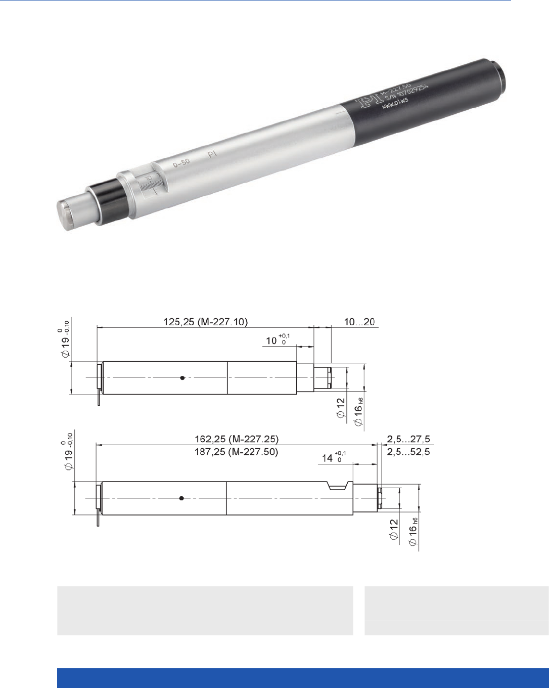
WWW.PI.WS
218
With Optional Piezo Drive
M-227
High-Resolution Linear Actuator with DC Motor
>> Incremental Encoder
Technology Glossary ...................... page 290
Applications
n General Automation
n Min. incremental motion 0.05 µm
n Nonrotating end piece
n Flat tip included
n Subnanometer resolution with optional
piezo drive
n For installing into mechanical systems
with external limit switches
M-227, dimensions in mm

MOTION | POSITIONING
219
M-227.10
M-227.25
M-227.50
Unit Tolerance
Motion and positioning
Travel range 10 / 25 / 50 mm
Integrated sensor Rotary encoder
Sensor resolution 2048 Cts./rev.
Design resolution 0.0035 µm typ.
Minimum incremental motion 0.05 µm typ.
Backlash 10 µm typ.
Unidirectional repeatability ±0.1 µm typ.
Velocity 0.75 mm/s max.
Mechanical properties
Drive screw Leadscrew
Thread pitch 0.5 mm
Gear ratio 69.12:1
Push/pull force (1) 40 N max.
Permissible lateral force 0.1 N max.
Drive properties
Motor type DC gear motor
Operating voltage 0 to ±12 V
Motor power 1.78 W nominal
Miscellaneous
Operating temperature range –20 to 65 °C
Material Aluminum anodized,
chrome steel
Mass 0.16 / 0.22 / 0.26 kg ±5 %
Cable length 0.1 m + 3 m extension
cable (included)
m ±10 mm
Connector Sub-D 15
Recommended controllers / drivers C-863
C-884
(1) Higher forces on request.
Ask about custom designs!
Linear Actuators
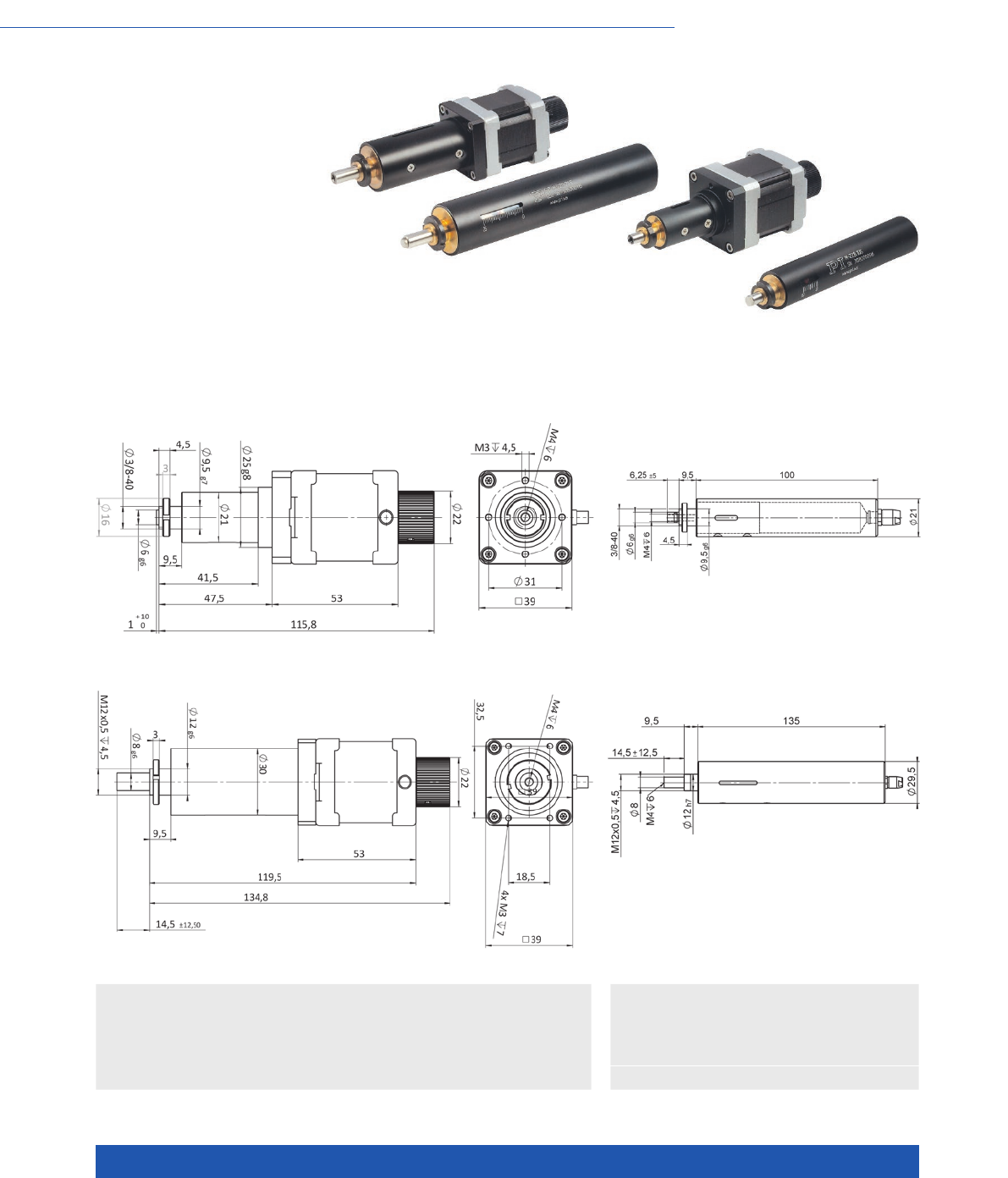
WWW.PI.WS
220
Compact and Extremely Inexpensive
M-228 / M-229 High-Resolution
Linear Actuator with Stepper Motor
n Travel ranges 10 and 25 mm
n High load capacity 80 N
n Resolution 0.36 nm with gearhead version
n Velocity to 4 mm/s
n Direct drive versions include handwheel
n Noncontact limit and reference point switches
>> Incremental Encoder
Technology Glossary ...................... page 290
Applications
n General Automation
n Scientific Instrumentation
M-228.10S, dimensions in mmM-228.11S, dimensions in mm
M-229.25S, dimensions in mmM-229.26S, dimensions in mm

MOTION | POSITIONING
221
M-228.10S M-228.11S M-229.25S M-229.26S Unit Tolerance
Slim design Lower cost,
higher velocity
Slim design Lower cost,
higher velocity
Motion and positioning
Travel range 10 10 25 25 mm
Design resolution (1) 0.00036 0.00061 0.00036 0.00061 µm typ.
Min. incremental motion (1) 1 1 1 1 µm typ.
Backlash (2) 510 10 10 µm typ.
Unidirectional repeatability ±2 ±2 ±2 ±2 µm typ.
Velocity 1.5 41.5 4 mm/s max.
Reference point switch
repeatability
1 1 1 1 µm typ.
Mechanical properties
Drive screw type Leadscrew Leadscrew Leadscrew Leadscrew
Drive screw pitch 0.5 0.5 0.5 0.5 mm
Gear ratio 256/9 – 256/9 –
Push/pull force capacity 20 50 50 80 N max.
Drive properties
Motor type 2-phase stepper
motor
2-phase stepper
motor
2-phase stepper
motor
2-phase stepper
motor
Step resolution 24 400 24 400 steps/rev.
Nominal current per phase 250 850 1000 850 mA max.
Limit and reference point
switches
Hall effect Hall effect Hall effect Hall effect
Miscellaneous
Operating temperature range –20 to 65 –20 to 65 –20 to 65 –20 to 65 °C
Material Al (anodized),
steel, brass
Al (anodized),
steel, brass
Al (anodized),
steel, brass
Al (anodized),
steel, brass
Mass 0.23 0.36 0.4 0.61 kg ±5 %
Cable length 0.5 m, incl. 3 m
cable
0.6 m, incl. 3 m
cable
0.5 m, incl. 3 m
cable
0.6 m, incl. 3 m
cable
m ±10 mm
Connector Sub-D 15 Sub-D 15 Sub-D 15 Sub-D 15
Recommended controller C-663.12 C-663.12 C-663.12 C-663.12
(1) With recommended controller.
(2) With preload.
Avoid lateral forces on the pusher!
Ask about custom designs!
Linear Actuators
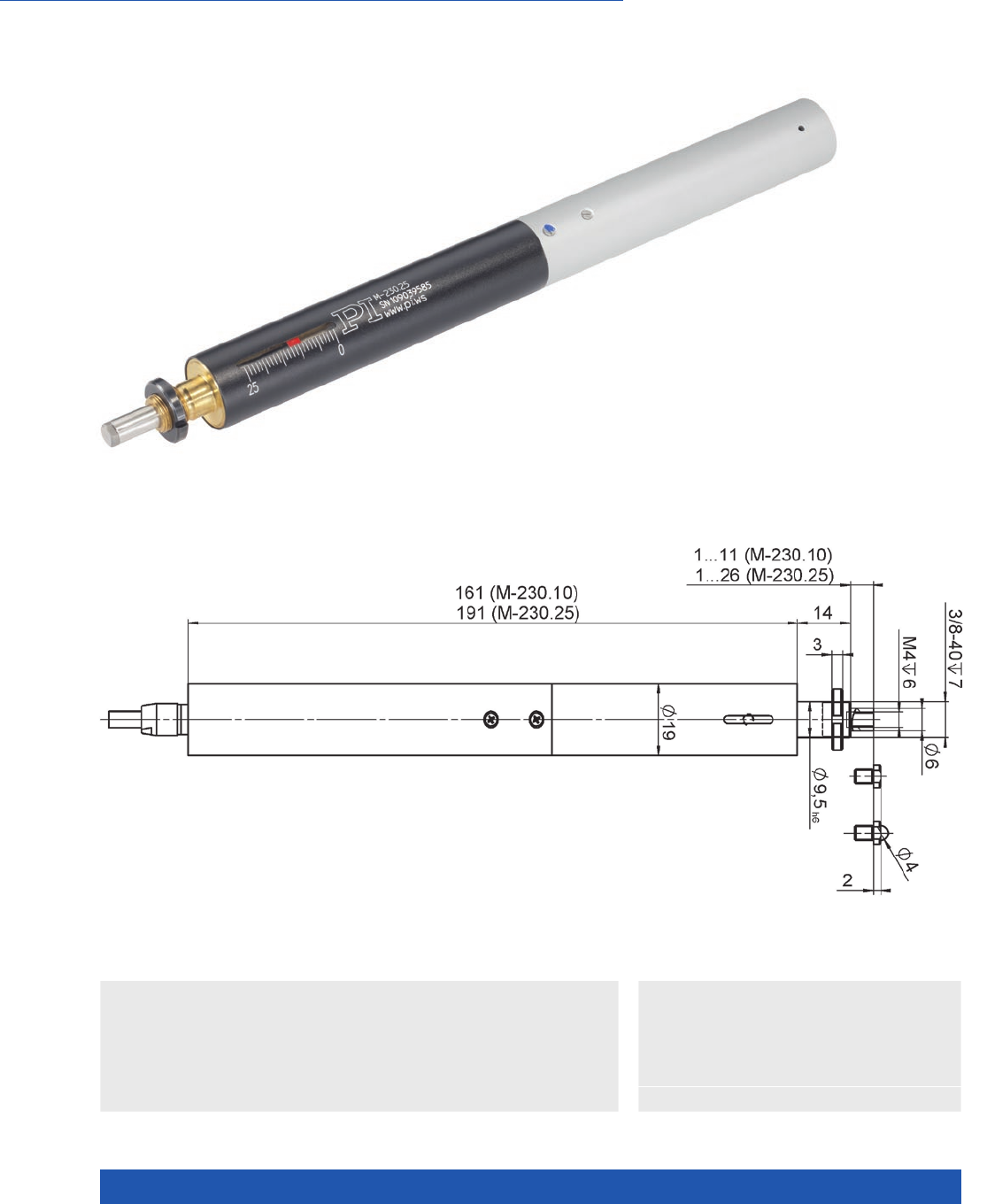
WWW.PI.WS
222
Nonrotating Tip, Limit Switches
M-230 High-Resolution
Linear Actuator with DC Motor
>> Incremental Encoder
Technology Glossary ...................... page 290
Applications
n General Automation
n Optical Alignment
n Scientific Instrumentation
M-230, dimensions in mm
n Min. incremental motion 0.05 µm
n Travel ranges 10 and 25 mm
n Nonrotating end piece
n Velocity 0.8 mm/s
n MTBF >20000 h

MOTION | POSITIONING
223
Ask about custom designs!
M-230.10
M-230.25
Unit Tolerance
High precision, with DC gear motor
Motion and positioning
Travel range 10 / 25 mm
Integrated sensor Rotary encoder
Sensor resolution 2048 Cts./rev.
Design resolution 0.0046 µm typ.
Minimum incremental motion 0.05 µm typ.
Backlash 2 µm typ.
Unidirectional repeatability ±0.1 µm typ.
Velocity 0.8 mm/s max.
Reference point switch repeatability 1 µm typ.
Mechanical properties
Drive screw Leadscrew
Thread pitch 0.4 mm
Gear ratio 42.92063:1
Push/pull force capacity 70 N max.
Permissible lateral force 30 / 20 N max.
Drive properties
Motor type DC gear motor
Operating voltage 0 to ±12 V
Motor power 1.78 W nominal
Limit and reference point switches Hall effect
Miscellaneous
Operating temperature range –20 to 65 °C
Material Al (anodized), steel, brass
Mass 0.3 / 0.35 kg ±5 %
Connector 15-pin sub-D, incl. encoder driver
Recommended controllers /
drivers
C-863
C-884
Linear Actuators
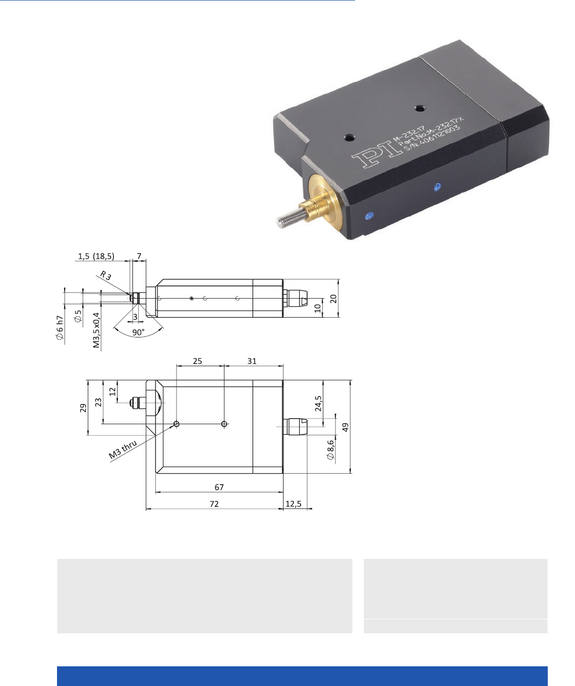
WWW.PI.WS
224
Compact due to Folded Drive
M-232 High-Resolution
Linear Actuator with DC Motor
>> Incremental Encoder
Technology Glossary ...................... page 290
Applications
n General Automation
n Optical Alignment
n Scientific Instrumentation
M-232, dimensions in mm
n Travel range 17 mm
n Min. incremental motion 0.1 µm
n Velocity to 1.5 mm/s
n Closed-loop DC motors
n Rotating end piece, rotating pusher
n MTBF >5000 h

MOTION | POSITIONING
225
Avoid lateral forces on the pusher!
Ask about custom designs!
M-232.17 Unit Tolerance
High resolution, closed loop
Motion and positioning
Travel range 17 mm
Integrated sensor Rotary encoder
Sensor resolution 2048 Cts./rev.
Design resolution 0.007 µm typ.
Minimum incremental motion 0.1 µm typ.
Backlash 2 µm typ.
Unidirectional repeatability ±0.2 µm typ.
Velocity 1.5 mm/s max.
Mechanical properties
Drive screw Leadscrew
Thread pitch 0.4 mm
Gear ratio 28.44444:1
Motor resolution – steps/rev.
Push/pull force 40 N max.
Drive properties
Motor type DC gear motor
Operating voltage 0 to ±12 V
Motor power 1.78 W
Limit switches Hall effect
Miscellaneous
Operating temperature range –20 to 65 °C
Material Aluminum anodized, chrome steel
Mass 0.17 kg ±5 %
Cable length 0.5 + 3 m extension cable (included) m ±10 mm
Connector 15-pin sub-D, incl. encoder driver
Recommended controllers /
drivers
C-863
C-884
Linear Actuators
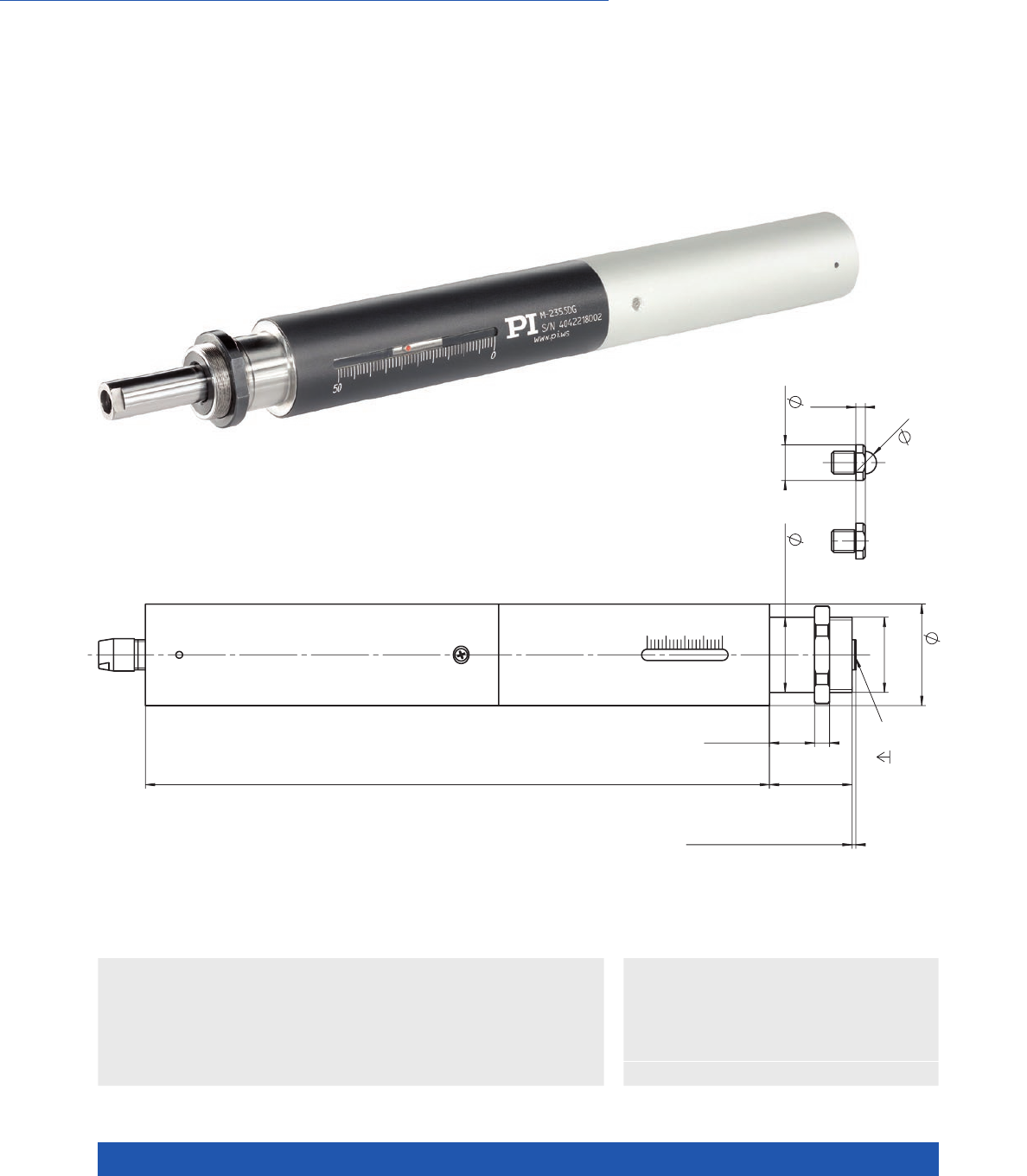
WWW.PI.WS
226
Highly Dynamic, High Forces up to 120 N
M-235 High-Resolution
Linear Actuator with DC Motor
>> Incremental Encoder
Technology Glossary ...................... page 290
Applications
n General Automation
n Optical Alignment
n Scientific Instrumentation
n Travel ranges 20 and 50 mm
n Min. incremental motion to 0.1 µm
n DC motor allows high velocities
n Push/pull force capacity to 120 N
n MTBF >10000 h
n Nonrotating end piece
n Recirculating ball screw
M
20
x0,5
4
22
min.
12
27
1
...21 (M-235.2Dx)
1...51 (M-235.5Dx)
166
(M-235.2Dx)
196 (M-235.5Dx)
2,5
6
20 h6
9,5
M6
10
M-235.2DD, M-235.2DG, M-235.5DD
and M-235.5DG, dimensions in mm

MOTION | POSITIONING
227
Ask about custom designs!
M-235.2DG
M-235.5DG
M-235.2DD
M-235.5DD
Unit Tolerance
High precision,
with DC gear motor
High dynamics
Motion and positioning
Travel range 20 / 50 20 / 50 mm
Integrated sensor Rotary encoder Rotary encoder
Sensor resolution 2048 2048 Cts./rev.
Design resolution 0.016 0.5 µm typ.
Minimum incremental
motion
0.1 1.5 µm typ.
Backlash 2 2 µm typ.
Unidirectional repeatability ±0.1 ±0.5 µm typ.
Velocity 2 30 mm/s max.
Mechanical properties
Gear ratio 29.6:1 –
Push/pull force 120 50 N max.
Permissible lateral force 8 8 N max.
Drive properties
Motor type DC gear motor DC motor
Operating voltage 0 to ±12 0 to ±12 V
Motor power 4 17 W nominal
Limit and reference point
switches
Hall effect Hall effect
Miscellaneous
Operating temperature
range
–20 to 65 –20 to 65 °C
Material Aluminum anodized,
chrome steel
Aluminum anodized,
chrome steel
Mass 0.55 / 0.7 0.5 / 0.65 kg ±5 %
Cable length 0.5 m, 3 m cables incl. 0.5 m, 3 m cables incl. m ±10 mm
Connector 15-pin sub-D,
incl. encoder driver
15-pin sub-D,
incl. encoder driver
Recommended
controllers / drivers
C-863
C-884
C-863
C-884
Linear Actuators
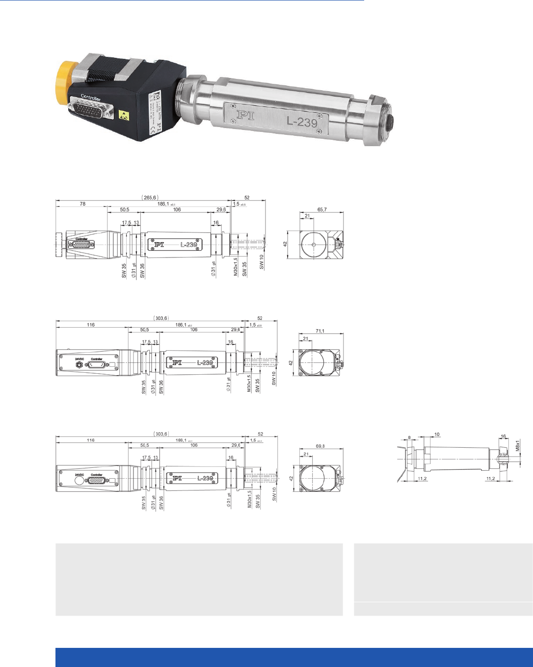
WWW.PI.WS
228
Dynamic, High-Resolution Precision Drive
L-239 High-Load Linear Actuator
>> ActiveDrive
>> Incremental Encoder
>> Vacuum-Compatible Versions
Technology Glossary ...................... page 290
Applications
n Electronics Manufacturing
n General Automation
n Optical Alignment
n Precision Micro Assembly
n Scientific Instrumentation
n Semiconductor
L-239.50SD with stepper motor, dimensions in mm
L-239.50AD with ActiveDrive DC motor, dimensions in mm
n Robust design for industrial
environments
n High feed force to 300 N
n Travel range 52 mm (2”)
n Minimum incremental motion
0.1 µm
n Velocity to 50 mm/s
n Preloaded, low-friction ball screw
n Vacuum-compatible versions to
10–9 hPa on request
n Stepper, DC and BLDC motors
L-239 shaft, dimensions in mmL-239.033232 with DC motor and L-239.035232 with brushless DC motor, dimensions in mm

MOTION | POSITIONING
229
All cables required for operation with the recommended controller are included in the scope of delivery.
The cable length is 3 m. Cable for connecting to other controllers can be ordered as accessory.
Ask about custom designs!
L-239.50AD
L-239.033232
L-239.035232
L-239.50SD Unit Tolerance
Motion
Active axis X X
Travel range 52 52 mm
Velocity 50 25 mm/s max.
Positioning
Integrated sensor Rotary encoder –
Sensor resolution 20000 – Counts./rev.
Design resolution 0.05 5 (full step) µm typ.
Minimum incremental
motion
0.2 0.1 µm typ.
Unidirectional repeatability 0.2 0.1 µm typ.
Bidirectional repeatability ±1 ±1 µm typ.
Limit and reference point
switches
Hall effect Hall effect
Mechanical properties
Guide type Recirculating ball bearings Recirculating ball bearings
Drive screw type Ball screw Ball screw
Drive screw pitch 1 1 mm
Push/pull force 300 300 N max.
Holding force, power off 40 80
Permissible lateral force 10 10 N max.
L-239.50AD L-239.50SD L-239.033232 L-239.035232 Unit Tolerance
Drive properties
Motor type DC motor with
PWM control
2-phase
stepper motor
DC motor BLDC motor
Operating voltage, nominal 24 24 24 24 V nom.
Operating voltage, max. 24 48 48 48 max.
Step resolution – 200 – – Full steps/rev.
Miscellaneous
Operating temperature
range
5 to 40 5 to 40 5 to 40 5 to 40 °C
Material Aluminum,
stainless steel
Aluminum,
stainless steel
Aluminum,
stainless steel
Aluminum,
stainless steel
Mass 1.72 1.65 1.75 1.75 kg ±5 %
Moved mass 0.155 0.155 0.155 0.155 kg ±5 %
Connector Sub-D 15 (m) HD Sub-D 26
(m)
HD Sub-D 26
(m)
HD Sub-D 26
(m)
Recommended
controllers / drivers
C-863
(single axis)
C-884
(up to 6 axes)
C-885 with
C-863.20C885
(to 40 axes)
ACS modular
controller
C-663.12
(single axis)
SMC Hydra
(double axis)
C-885 with
C-663.12C885
(up to 20 axes)
ACS modular
controller
C-863
(single axis)
C-884
(up to 6 axes)
C-885 with
C-863.20C885
(to 40 axes)
ACS modular
controller
C-891
(single axis)
C-885 with
C-891.10C885
(up to 20 axes)
ACS modular
controller
Linear Actuators
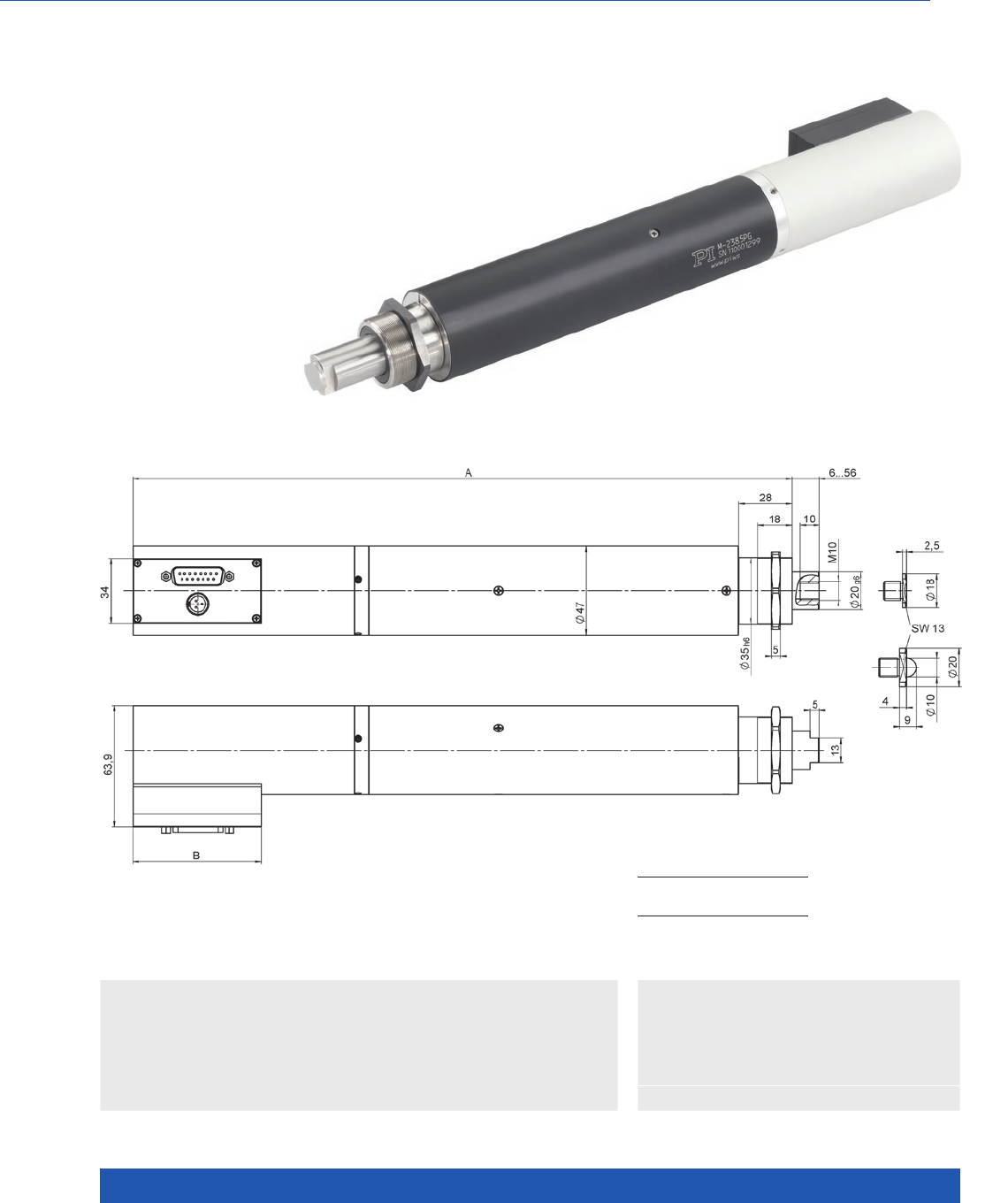
WWW.PI.WS
230
Dynamic, High-Resolution Precision Drive
M-238 High-Load Linear Actuator with DC Motor
>> ActiveDrive
>> Incremental Encoder
>> Linear Encoder
Technology Glossary ...................... page 290
Applications
n General Automation
n Optical Alignment
n Scientific Instrumentation
n Optional linear encoder for direct position
measurement
n High load capacity to 400 N
n Travel range 50 mm
n Resolution to 0.1 µm
n Velocity to 30 mm/s
n Nonrotating end piece
n Recirculating ball screw
M-238, dimensions in mm
A B
336,2
347, 2
90
67,6
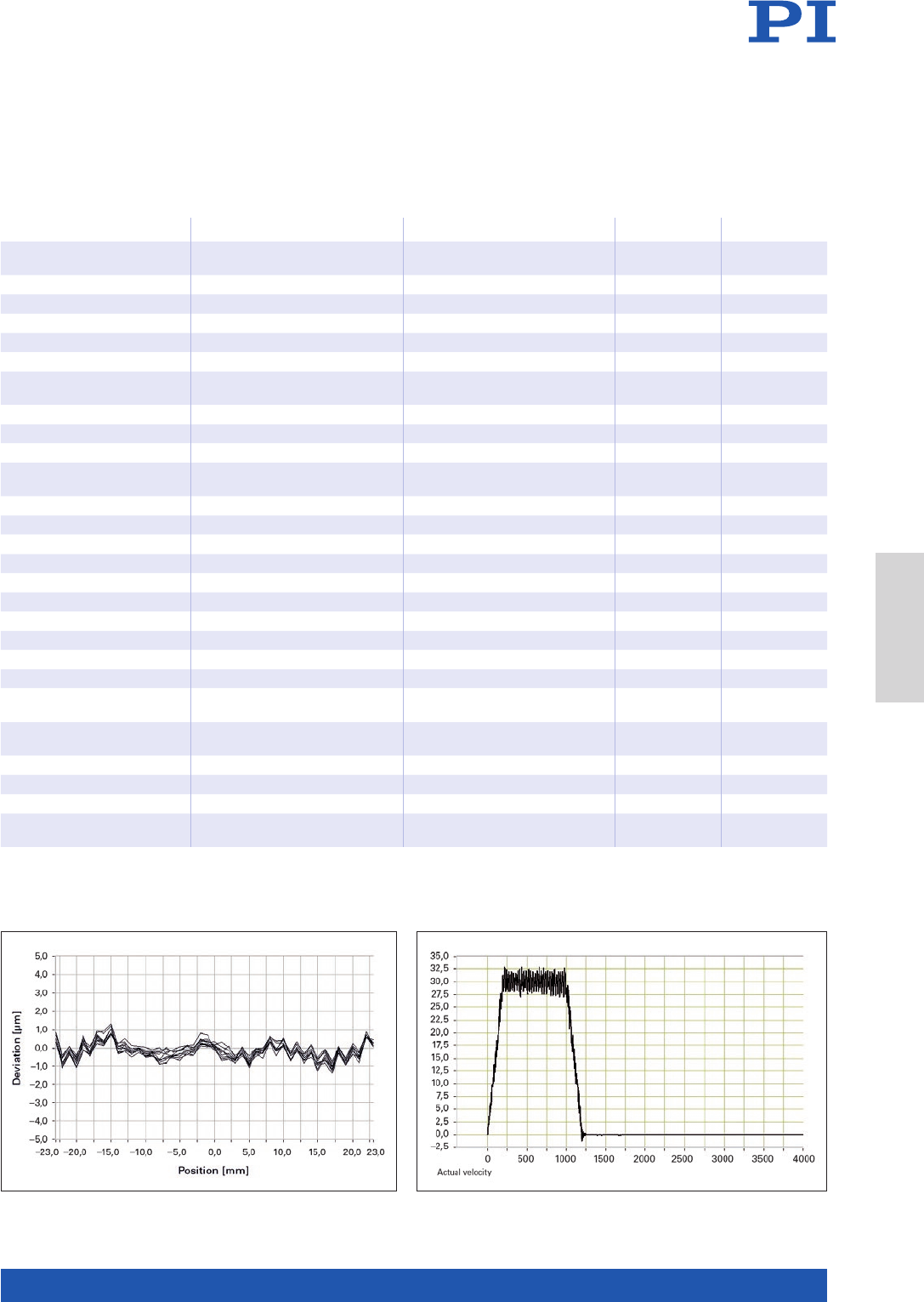
MOTION | POSITIONING
231
Ask about custom designs!
M-238.5PG M-238.5PL Unit Tolerance
Rotary encoder
on motor shaft
Highest precision
with linear encoder
Motion and positioning
Travel range 50 50 mm
Integrated sensor Rotary encoder Linear encoder
Sensor resolution 4000 cts/rev 0.1 µm
Design resolution 0.13 0.1 µm typ.
Minimum incremental
motion
0.5 0.3 µm typ.
Backlash 3 1 µm typ.
Unidirectional repeatability ±1 ±0.3 µm typ.
Velocity 30 30 mm/s max.
Reference point switch
repeatability
1 1 µm typ.
Mechanical properties
Drive screw pitch 2 2 mm
Gear ratio 3.71:1 3.71:1
Push/pull force 400 400 N max.
Permissible lateral force 100 100 N max.
Drive properties
Motor type DC motor, ActiveDrive DC motor, ActiveDrive
Motor voltage 24 V 24 V V
Motor power 80 80 W nominal
Miscellaneous
Operating temperature
range
–10 to 50 –10 to 50 °C
Material Aluminum anodized, chrome
steel
Aluminum anodized, chrome
steel
Mass 2.4 2.4 kg ±5 %
Cable length 3 3 m ±10 mm
Connector Sub-D 15 Sub-D 15
Recommended
controllers / drivers
C-863
C-884
C-863
C-884
The repeatability of the M-238.5PL with linear encoder is less than 0.3 µm. The velocity constancy of an M-238.5PL at 30 mm/s.
Linear Actuators
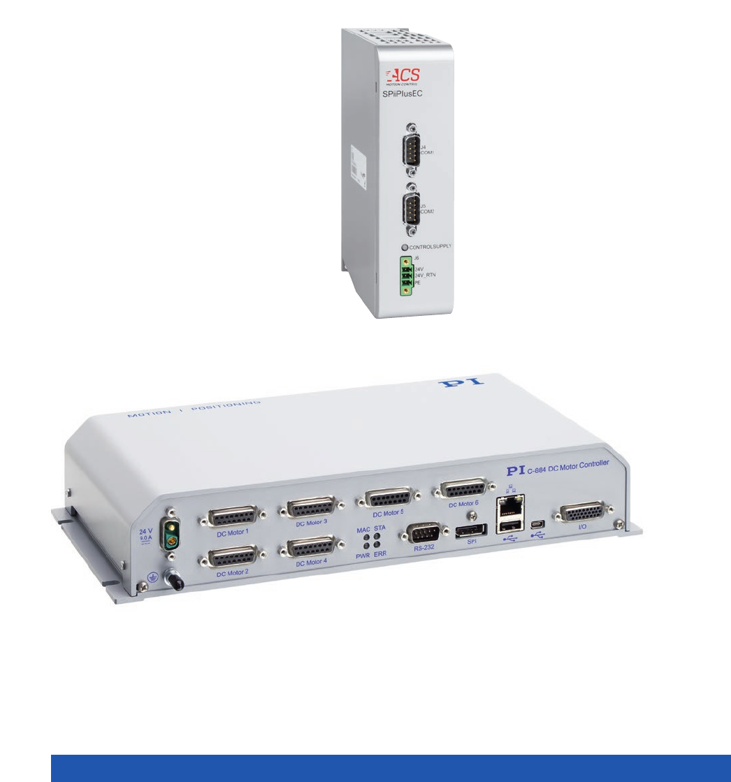
WWW.PI.WS
232
Motion Control

MOTION | POSITIONING
233
Industrial motion control ......................................................................................................................................................... 234
Solutions for Motion Centric Industrial Automation ...................................................... 234
Overview of Available ACS Motion Control Modules .................................................... 236
ACS Motion Control for Motion Centric Industrial Automation ..................................... 238
A-81x PIglide Motion Controller for 1, 2 or 4 Axes ........................................................ 242
A-82x PIglide Motion Controller for 4, 6 or 8 Axes ........................................................ 244
SMC Hydra Universal Motion Controller ....................................................................... 246
C-891 PIMag® Motion Controller for Magnetic Direct Drives ......................................... 248
Modular Multi-Channel Piezo Controllers ............................................................................................................................... 250
C-885 PIMotionMaster ................................................................................................... 250
Stepper Motor Controllers ....................................................................................................................................................... 252
C-663.12 Mercury Step Stepper Motor Controller, 1 Axis .............................................. 252
DC Motor Controllers ............................................................................................................................................................... 254
C-863 Mercury Servo Controller .................................................................................... 254
C-884.4DC / C-884.6DC Motion Controller for DC Motors, 4 or 6 Axess ......................... 256
Voice Coil Controllers .............................................................................................................................................................. 258
C-413 PIMag® Motion Controller .................................................................................... 258
Motion Control
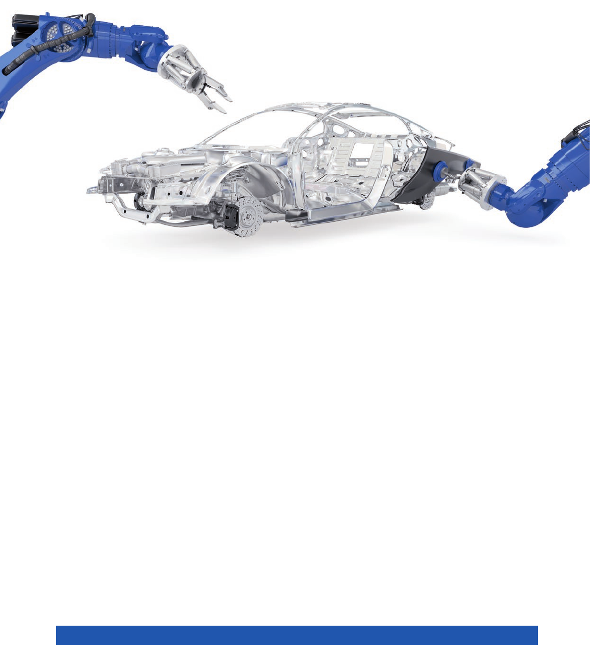
WWW.PI.WS
234
Solutions for Motion Centric
Industrial Automation
n Functional safety
n Communication via fieldbus interfaces
n Autotuning
n Synchronization of the individual axes in the system
n Multidimensional motion profiles
n 3-DOF compensation of the position error
n Yaw compensation for gantry solutions
n Suppression of system oscillation
n Robust control behavior
n Easy integration into the higher-level automation
environment
SMARTER MOTION
AND POSITIONING
What makes a positioner and motion solu-
tion smart? What functions and features
must a high-performance control solution
offer to make smart motion and position-
ing possible? PI has identified the follow-
ing list of basic requirements that make
it possible to offer solutions for industrial
applications that fulfill the high demands
for precision and dynamics irrespective of
the number of motion axes.
Positioning and motion tasks in industrial automation such as those in assembly, semiconductor manufac-
turing, mechanical engineering, laser material processing, inspection systems or in additive manufacturing
demand solutions that need to be robust and reliable. Submicrometer accuracy, exact position reproducibility,
high dynamics, and throughput are just as essential. This is particularly the case with industry 4.0 where
safety and simple networking options play an important role.
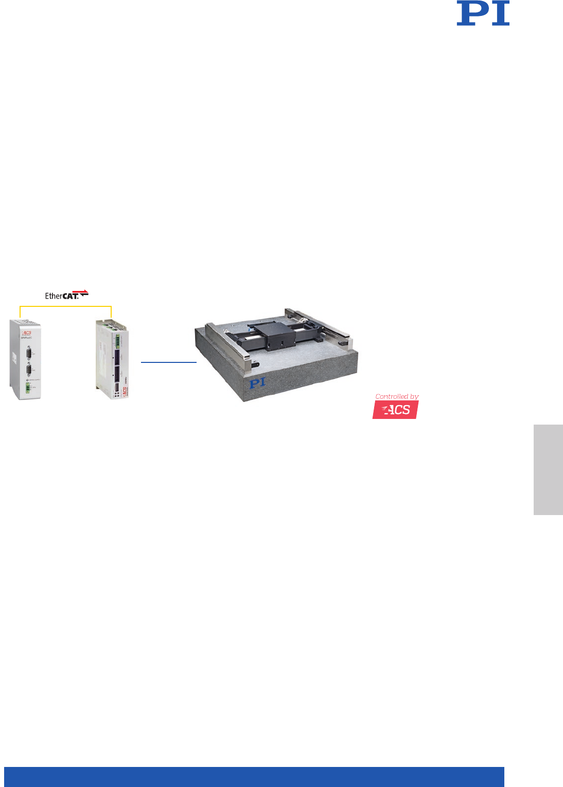
MOTION | POSITIONING
235
HIGH-PERFORMANCE MOTION CONTROL SYSTEMS
ACS Motion Control offers distributed-architecture motion control systems, completely modular, with com-
ponents organized over three levels: The first level is the user interface. This is basically the host software
and allows communication with the motion system.
The devices on the second level are called motion controllers. The motion controller is responsible for com-
munication with the host software and also takes care of everything related to profile generation, trajectory,
macros, diagnostics, and so on. The position commands are sent to the universal drive modules on the third
level via an EtherCAT real-time network. In some products, the motion controller, the drives, and the power
supplies are integrated into one housing. These products are called control modules.
The universal drive modules on the third level include the digital servo processor (DSP). It performs the servo
positioning of the axes. The drive modules power and actuate the motors, handle the feedback devices,
manage the I/Os, and analyze the sensor signals for closed-loop positioning control.
COMPLETE SOLUTIONS FOR HIGH-THROUGHPUT
AND HIGH-PRECISION MULTI-AXIS APPLICATIONS
Those requirements can only be fulfilled when the mechanics, drive technology, and control electronics of
the positioning system are perfectly matched to each other.
A solution from a single-source supplier does not just offer the customer sophisticated positioning technology
and high-performance control solutions, but also faster start-up and high flexibility when implementing new
requirements.
UDMntSPiiPlusEC
Motion Control
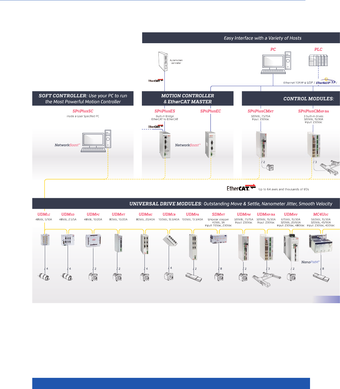
WWW.PI.WS
236
Overview of Available ACS Motion Control Modules
PI offers complete systems that implement the ACS motion control solutions
EtherCAT® is a registered trademark and patented technology, licensed by Beckhoff Automation GmbH, Germany.
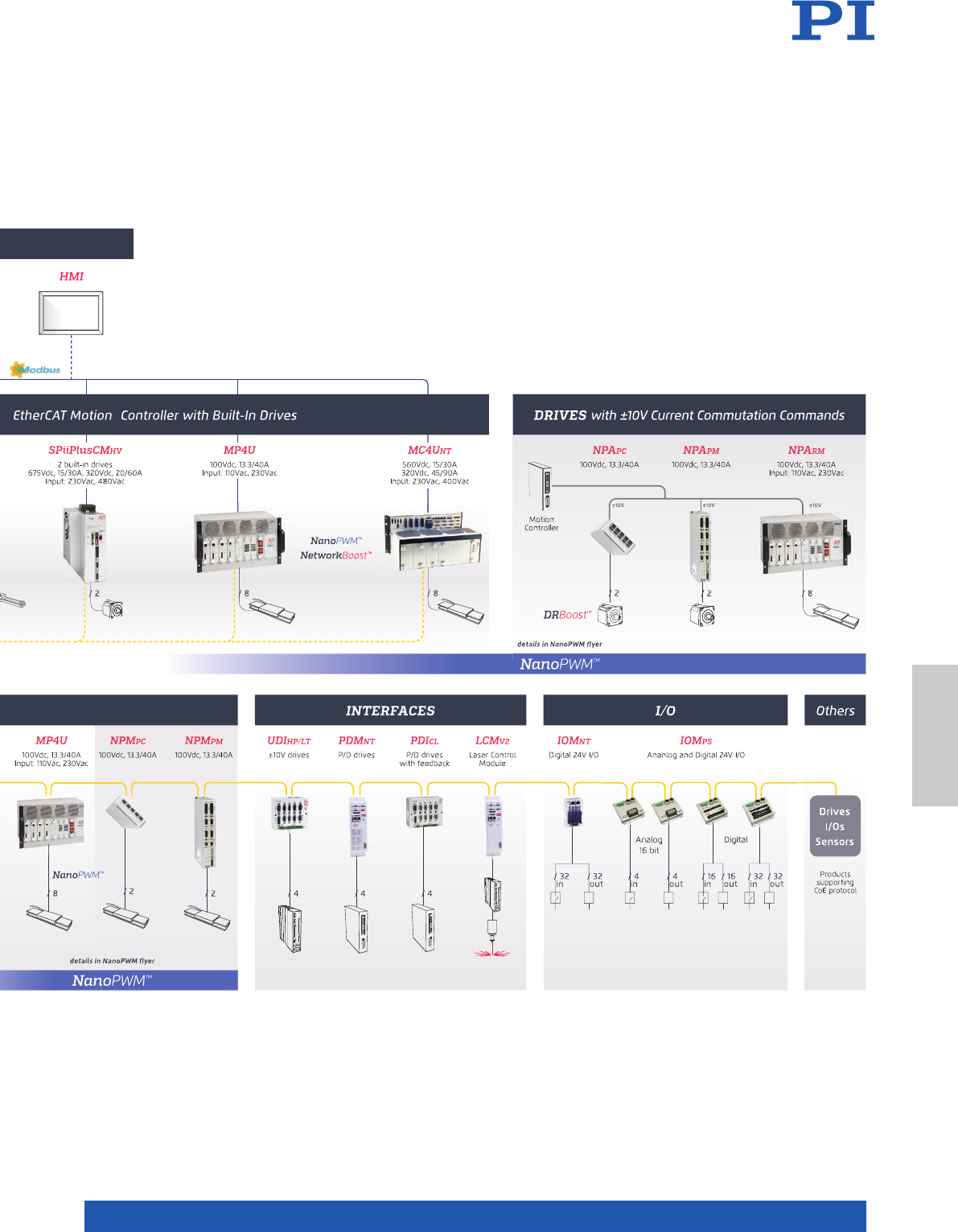
MOTION | POSITIONING
237
Motion Control
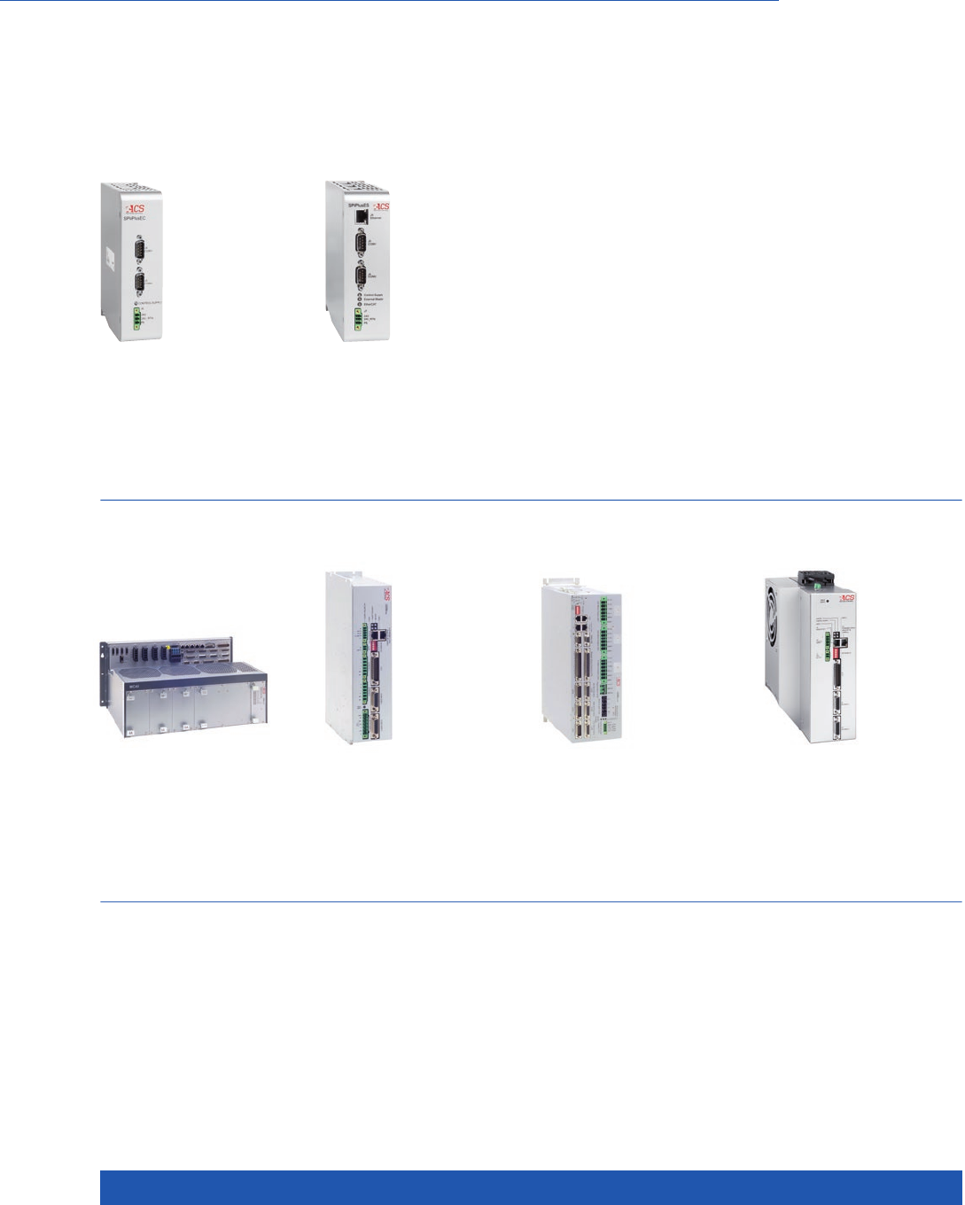
WWW.PI.WS
238
Available Modules
ACS Motion Control
for Motion Centric Industrial Automation
SPiiPlusEC Powerful Motion
Controller and EtherCAT®
Network Manager
up to 64 axes and thousands
of I/O’s
MC4Unt Customized Multi-
axis Control Using Standard
Components
2 to 8 drives, wide power
range
SPiiPlusES High Perfor-
mance Multi-Axis Controller
with Built-in EtherCAT®-to-
EtherCAT® Bridge
up to 64 axes and thousands
of I/O’s
SPiiPlusCMnt 32-Axis
EtherCAT® Master Control
Module with 2 Built-in Drives
1, 2 drives 85 – 265 V-AC,
up to 7.5/15 A
SPiiPlusSPC Smart
Processing Commander
Machine Control Interface
for High-Precision Laser
Processing Applications
SPiiPlusSMC Smart
Motion Commander
Customizable CNC HMI
Platform for High-Precision
Machining and Processing
Applications
SPiiPlusSC Software Based
Powerful Motion Controller
and EtherCAT® Network
Manager
up to 64 axes and thousands
of I/O’s
SPiiPlusCMhp/ba 32-Axis
EtherCAT® Master Control
Module with 3 Built-in Drives
1 to 3 drives, 85 – 265 V-AC,
up to 15/30 A
SPiiPlusCMhv 32-Axis
EtherCAT® Master Control
Module with 2 Built-in
High-Voltage Drives
1, 2 axes, 230 – 480 V-AC, up to
15/30 A, or 230 V-AC, 20/60 A
EtherCAT® Motion Controller
Control Modules
User Interface Software Applications
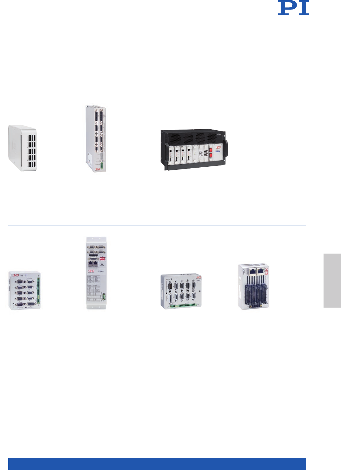
MOTION | POSITIONING
239
NPApc Single/Dual Axis
NanoPWM Drive with ±10 V
Current Commutation
Commands
1,2 drives, 12 – 100 V, up to
13.3/40 A, PCB mount
NPApm Single/Dual Axis
NanoPWM Drive with ±10 V
Current Commutation
Commands
1,2 drives, 12 – 100 V, up to
13.3/40 A
NPArm 2 to 8 Axis NanoPWM
Drive system with ±10V Current
Commutation Commands and
Power Supply
2 to 8 drives, up to 96 V, up to
13.3/40 A, rack mount
Drives with ±10 V Interface
UDIhp/lt EtherCAT®
Dual/Quad Axis Motor
Drive Interface
2 to 4 axes, ±10 V interface
to external motor drives
IOMnt EtherCAT®
Digital I/O Module
up to 32 digital inputs
and outputs, 24 V-DC
PDMnt EtherCAT® Quad
Axis P/D Interface Module
4 axes, Pulse/Direction
interface to external motor
drives
PDIcl EtherCAT® Dual/Quad
Axis Interface Module for
P/D with Feedback
2, 4 axes, Pulse/Direction
interface to external motor
drives
Interfaces
Motion Control
WWW.PI.WS
240
UDMpm EtherCAT®
Single/Dual Axis Drive
Module
1, 2 drives, 85 – 265 V,
up to 7.5/15 A
UDMhp/ba EtherCAT®
Drive Module, Compact,
Powerful
1 to 3 drives, 85 – 265 V-AC,
up to 15/30 A
UDMhv EtherCAT® Single/
Dual Axis High Voltage Drive
Module
1, 2 drives, 230 – 480 V-AC,
up to 15/30 A or 230 V-AC
20/60 A
Universal Drive Modules with AC
UDMnt EtherCAT® Single/
Dual Axis Drive Module
1, 2 drives, 12 – 80 V, up to
10/20 A
UDMmc EtherCAT® Drive Module,
Compact, Cost Effective
2, 4 drives, 12 – 80 V, up to
20/40 A
Universal Drive Modules with 80 V DC
UDMlc EtherCAT® Dual/
Quad Axis Drive Module
2, 4 drives, 12 – 48 V, up to
5/10 A
UDMsd EtherCAT® Dual/
Quad Axis Drive Module
2, 4 drives, 12 – 48 V, up to
2.5/5 A
UDMpc EtherCAT® Single/
Dual Axis Drive Module
1, 2 drives, 24 – 48 V, up to
10/20 A, PCB mount
Universal Drive Modules with 48 V DC
Available Modules
ACS Motion Control
for Motion Centric Industrial Automation
MOTION | POSITIONING
241
NPMpc EtherCAT® Single/Dual
Axis NanoPWM Drive Module
1, 2 drives, 12 – 100 V, up to
13.3/40 A, PCB mount
UDMcb Economical EtherCAT®
Single/Dual Axis Drive Module
1, 2 drives, up to 100 V,
13.3/40 A, PCB mount
SDMnt EtherCAT® 4/8 Axis
Stepper Drive Module
4, 8 unipolar stepper motor
drives, 40 V, 3 A
NPMpm EtherCAT® Single/Dual
Axis NanoPWM Drive Module
1, 2 drives, 12 – 100 V, up to
13.3/40 A
UDMpa EtherCAT® Single/
Dual Axis Drive Module
1, 2 drives, up to 100 V,
13.3/40 A
Universal Drive Modules with NanoPWM
Other Universal Drive Modules
Stepper Drive Module
Motion Control
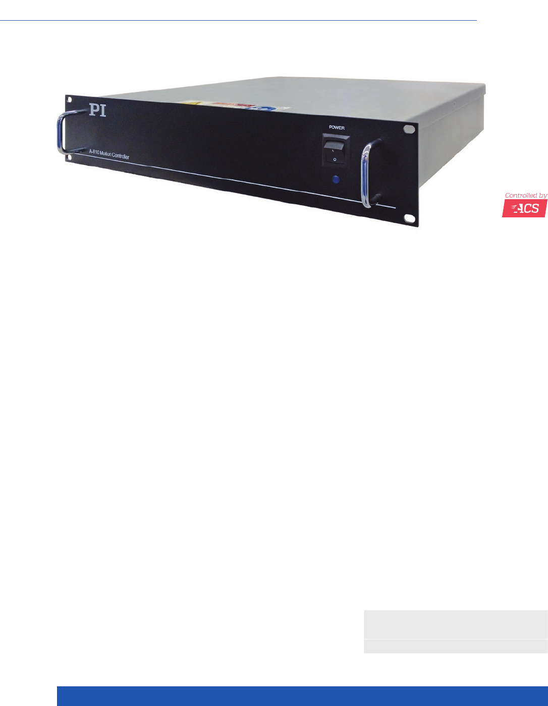
WWW.PI.WS
242
n 1, 2, & 4 motion axes
n Fully integrated closed-loop servo control, amplifier module,
and power supplies
n For voice coil drives, DC motors and brushless 3-phase motors
n Quiet PWM drives
n Encoder inputs support sine/cosine and BiSS-C
n 5 A continuous current / 10 A peak output current per axis
For Stages with Direct Drive, TCP/IP Interface
A-81x
PIglide Motion Controller for 1, 2 or 4 Axes
>> Extensive Software Package
Technology Glossary ...................... page 290
Options
n Absolute encoders or incremental encoders
(can be combined individually according to
customer specifications for all axes of the
controller)
n G-Code programming
n Input shaping
n Additional control axes for external drives
via EtherCAT®
n Alternative customized packaging for OEM
designs
Overview
The A-81x motion controller series from PI offers a fully integrated electronics
solution with controller, drives, and power supplies in a compact 19-inch rack
unit. The A-81x controllers are designed and optimized for PIglide air bearing
stages that are equipped with direct drive linear and rotation servo motors, and
high-resolution encoders.
Standard options include inputs for incremental sine/cosine and absolute
encoders that use the BiSS-C data protocol. Support for sine/cosine encoders
has an integrated interpolation factor of 16384x. All controllers feature inte-
grated flash memory for stored motion programs and parameters.
The A-81x controllers can be operated in stand-alone mode running stored
programs, or controlled via an external PC. A PC is required for programming
and startup. All software is supplied with the controller.
If the controller is purchased together with a PIglide air bearing stage or posi-
tioning system, PI will perform the servo tuning, startup of the controller, and
error calibration, and supply a complete ready-to-use positioning system.
The A-81x motion controller features the state of the art ACS SPiiPlusEC motion
controller and EtherCAT® master, and includes ServoBoost™ for up to eight
axes of motion. ServoBoost™ provides better, more consistent servo perfor-
mance that is insensitive to noise or changes in the system.

MOTION | POSITIONING
243
A-811.21x00 A-812.21x00 A-814.21x00
Number of axes 1 2 4
Controller type Closed-loop servo control
(PID), parameter changing
during operation
Closed-loop servo control
(PID), parameter changing
during operation
Closed-loop servo control
(PID), parameter changing
during operation
Servo-frequency position
control
10 kHz 10 kHz 10 kHz
Servo frequency current
control
20 kHz 20 kHz 20 kHz
Trajectory profiles Point-to-point, jog, s-curve Point-to-point, jog, s-curve,
interpolated coordinated
multi-axis profiles
Point-to-point, jog, s-curve,
interpolated coordinated
multi-axis profiles
Cooling Fan on the side (continuous
operation, constant speed)
Fan on the side (continuous
operation, constant speed)
Fan on the side (continuous
operation, constant speed)
Drive type PWM PWM PWM
Motor types Voice coil
Brushed DC motor
Brushless 3-phase motor
with sine commutation
Voice coil
Brushed DC motor
Brushless 3-phase motor
with sine commutation
Voice coil
Brushed DC motor
Brushless 3-phase motor
with sine commutation
Encoder options
(factory default)
(Can be configured indi-
vidually for combinations
according to customer
specifications)
Incremental sine/cosine
(1 Vpp)
A/B quadrature (RS-422)
(on request),
Absolute encoder BiSS-C
Incremental sine/cosine
(1 Vpp)
A/B quadrature (RS-422)
(on request),
Absolute encoder BiSS-C
Incremental sine/cosine
(1 Vpp)
A/B quadrature (RS-422)
(on request),
Absolute encoder BiSS-C
Output current (per axis) 5 A continuous operation,
10 A peak
5 A continuous operation,
10 A peak
5 A continuous operation,
10 A peak
Interfaces
Communication Ethernet: TCP/IP,
100/1000 Mbps
Ethernet/IP
Modbus
Ethernet: TCP/IP,
100/1000 Mbps
Ethernet/IP
Modbus
Ethernet: TCP/IP,
100/1000 Mbps
Ethernet/IP
Modbus
User I/O (without reference
and limit switch)
2 × digital input, 24 V DC, sink
2 × digital output, 24 V DC,
source
1 × analog input, differential,
12 bit
1 × analog output, differential,
10 bit
1 × RS-422 high-speed output
for position trigger (PEG)
2 × digital input, 24 V DC, sink
2 × digital output, 24 V DC,
source
1 × analog input, differential,
12 bit
1 × analog output, differential,
10 bit
2 × RS-422 high-speed output
for position trigger (PEG)
4 × digital input, 24 V DC, sink
4 × digital output, 24 V DC,
source
2 × analog input, differential,
12 bit
2 × analog output, differential,
10 bit
4 × RS-422 high-speed output
for position trigger (PEG)
Interlock / motion-stop 1 × 24 V DC sink 1 × 24 V DC sink 1 x 24 V DC sink
Connector interface Rear panel connectors
Sub-D for motor and signal
connections
IEC 60320 type C14 for power
supply
Rear panel connectors
Sub-D for motor and signal
connections
IEC 60320 type C14 for power
supply
Rear panel connectors
Sub-D for motor and signal
connections
IEC 60320 type C14 for power
supply
Miscellaneous
Power supply 120 – 240 V AC,
single phase,
50 – 60 Hz (factory default),
600 W
120 – 240 V AC,
single phase,
50 – 60 Hz (factory default),
600 W
120 – 240 V AC,
single phase,
50 – 60 Hz (factory default),
600 W
Mass (approx.) 8.5 kg 8.5 kg 9.3 kg
Dimensions 19” rack unit,
483 mm × 88 mm × 487 mm
(incl. handles)
19” rack unit,
483 mm × 88 mm × 487 mm
(incl. handles)
19” rack unit,
483 mm × 88 mm × 487 mm
(incl. handles)
Motion Control
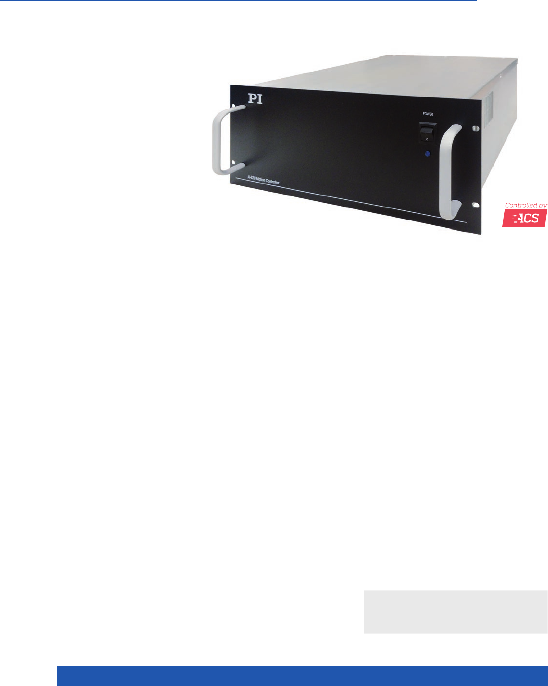
WWW.PI.WS
244
n 4, 6 or 8 high-performance motion axes
n Fully integrated closed-loop servo control, amplifier module,
and power supplies
n For voice coil drives, DC motors and brushless 3-phase motors
n Quiet PWM drives
n Encoder inputs support sine/cosine and BiSS-C
n 10 A continuous current / 20 A peak output current per axis
Options
n Absolute encoders or incremental encoders
(can be combined individually according to
customer specifications for all axes of the
controller)
n G-Code programming
n Input shaping
n Additional control axes for external drives
via EtherCAT®
n Alternative customized packaging for OEM
designs
For Stages with Direct Drive and High Power Requirements, TCP/IP Interface
A-82x
PIglide Motion Controller for 4, 6 or 8 Axes
>> Extensive Software Package
Technology Glossary ...................... page 290
Overview
The A-82x motion controller series from PI offers a fully integrated electronics
solution with controller, drives, and power supplies in a compact 4-U-high
19-inch rack unit. The A-824 supplies continuous power of 2 kW. The A-82x
controllers are designed and optimized for PIglide air bearing stages that are
equipped with direct drive linear and rotation servo motors, and high-resolution
encoders.
Standard options include inputs for incremental sine/cosine and absolute
encoders that use the BiSS-C data protocol. Support for sine/cosine encoders
has an integrated interpolation factor of 16384x. All controllers feature inte-
grated flash memory for stored motion programs and parameters.
The A-82x controllers can be operated in stand-alone mode running stored
programs, or controlled via an external PC. A PC is required for programming
and startup. All software is supplied with the controller.
If the controller is purchased together with a PIglide air bearing stage or posi-
tioning system, PI will perform the servo tuning, startup of the controller, and
error calibration, and supply a complete ready-to-use positioning system.
The A-82x motion controller features the state of the art ACS SPiiPlusEC motion
controller and EtherCAT® master, and includes ServoBoost™ for up to eight
axes of motion. ServoBoost™ provides better, more consistent servo perfor-
mance that is insensitive to noise or changes in the system.

MOTION | POSITIONING
245
A-824.21x00 A-826.21x00 A-828.21x00
Number of axes 4 6 8
Controller type Closed-loop servo control
(PID), parameter changing
during operation
Closed-loop servo control
(PID), parameter changing
during operation
Closed-loop servo control
(PID), parameter changing
during operation
Servo-frequency position
control
10 kHz 10 kHz 10 kHz
Servo frequency current
control
20 kHz 20 kHz 20 kHz
Trajectory profiles Point-to-point, jog, s-curve,
interpolated coordinated
multi-axis profiles
Point-to-point, jog, s-curve,
interpolated coordinated
multi-axis profiles
Point-to-point, jog, s-curve,
interpolated coordinated
multi-axis profiles
Cooling Fan on the side (continuous
operation, constant speed)
Fan on the side (continuous
operation, constant speed)
Fan on the side (continuous
operation, constant speed)
Drive type PWM PWM PWM
Motor types Voice coil
Brushed DC motor
Brushless 3-phase motor
with sine commutation
Voice coil
Brushed DC motor
Brushless 3-phase motor
with sine commutation
Voice coil
Brushed DC motor
Brushless 3-phase motor
with sine commutation
Encoder options
(factory default)
(Can be configured indi-
vidually for combinations
according to customer
specifications)
Incremental sine/cosine
(1 Vpp)
A/B quadrature (RS-422)
(on request),
Absolute encoder BiSS-C
Incremental sine/cosine
(1 Vpp)
A/B quadrature (RS-422)
(on request),
Absolute encoder BiSS-C
Incremental sine/cosine
(1 Vpp)
A/B quadrature (RS-422)
(on request),
Absolute encoder BiSS-C
Interpolation factor
sine/cosine encoder
4 x to 16384x (can be
adjusted by software)
4 x to 16384x (can be
adjusted by software)
4 x to 16384x (can be
adjusted by software)
Output voltage 72 VDC 72 VDC 72 VDC
Output current (per axis) 10 A continuous operation,
20 A peak (<1 s)
10 A continuous operation,
20 A peak (<1 s)
10 A continuous operation,
20 A peak (<1 s)
Output power (total) 1100 W continuous operation
3900 W peak
1700 W continuous operation
3900 W peak
2000 W continuous operation
3900 W peak
A-824.2x00 A-826.21x00 A-828.21x00
Miscellaneous
Power supply 200 – 240 V AC, single phase,
50 – 60 Hz
200 – 240 V AC, single phase,
50 – 60 Hz
200 – 240 V AC, single phase,
50 – 60 Hz
Mass (approx.) 13.6 kg 14.4 kg 15.2 kg
Dimensions 19” rack unit, 483 mm ×
171 mm × 495 mm
(incl. handles)
19” rack unit, 483 mm ×
171 mm × 495 mm
(incl. handles)
19” rack unit, 483 mm ×
171 mm × 495 mm
(incl. handles)
A-82x
Interfaces
Communication Ethernet: TCP/IP, 100/1000 Mbps
Ethernet/IP
Modbus
User I/O (without reference
and limit switch)
4 × digital input, 24 V DC, sink
3 × digital output, 24 V DC, source
2 × analog input, differential, 12 bit
2 × analog output, differential, 10 bit
4 × RS-422 high-speed output for position trigger (PEG)
Interlock / motion-stop 1 × 24 V DC
Connector interface Rear panel connectors
Sub-D for motor and signal connections
IEC 60320 type C20 for power supply
Motion Control
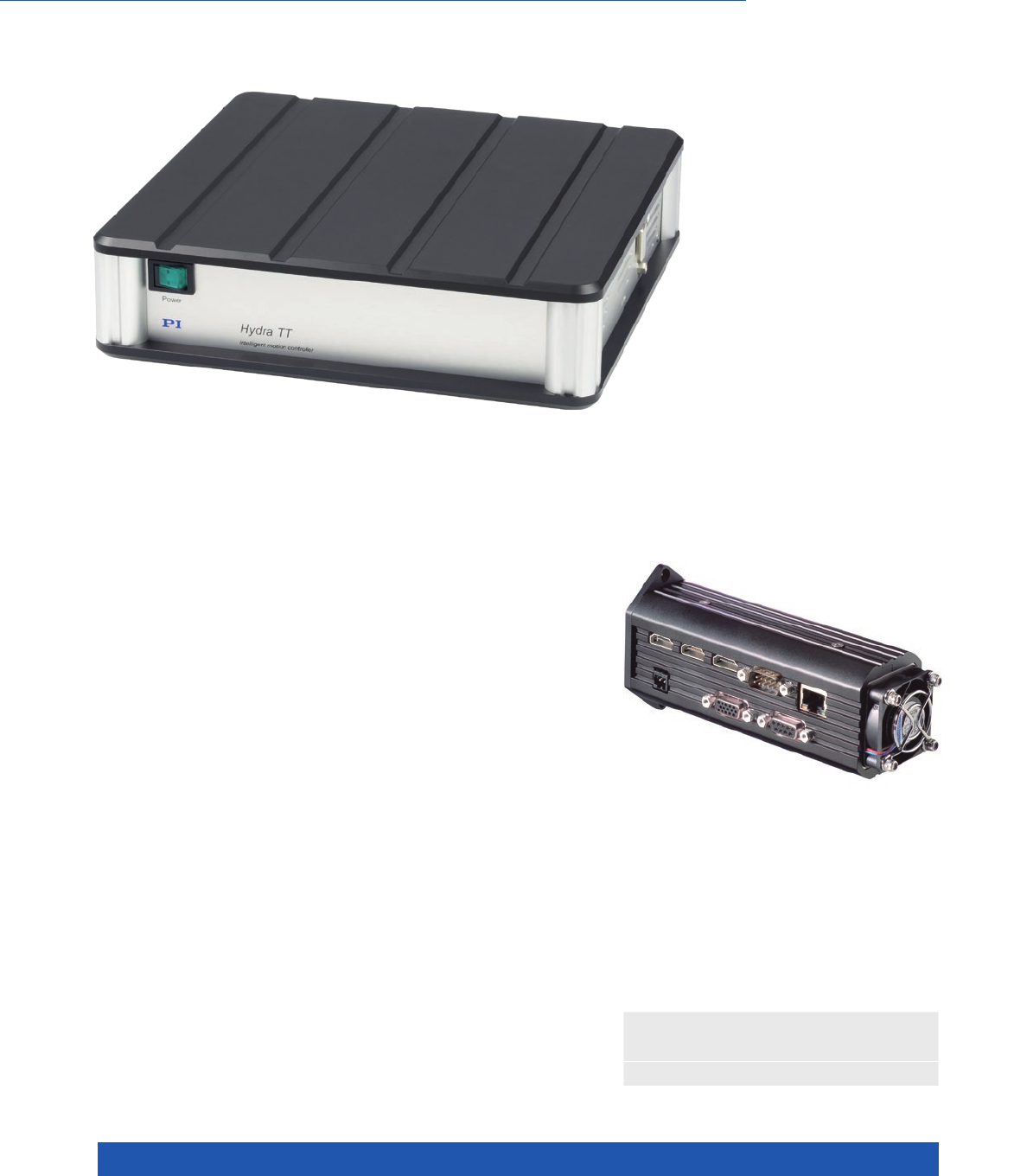
WWW.PI.WS
246
>> Extensive Software Package
Technology Glossary ...................... page 290
For Electromagnetic Motors
SMC Hydra Universal Motion Controller
n 2-D vector motion with linear interpolation, independent
single-axis motion
n For DC servo and brushless DC motors (BLDC), linear
and torque motors (2 / 3 phases), 2-phase stepper motors
n Digital inputs and outputs
n Optional: Encoder-based trigger output
n Optional: Position capture input: Position detection
in real time via digital input
n Optional: Dynamic position correction
n Joystick operation via CAN bus
Compact SMC Hydra CM
2-axis motion controller

MOTION | POSITIONING
247
SMC Hydra TT SMC Hydra CM SMC Hydra RM
Function Motion controller for
electromagnetic motors
Benchtop device with
integrated power supply
Motion controller for
electromagnetic motors
Compact device
Motion controller for
electromagnetic motors
19” rack unit with
integrated power supply
Axes 2 2 2 / 4
Sensor channels 2 2 2 / 4
Miscellaneous
Operating voltage 90 – 260 V, integrated wide-
range-input power supply
24 V / 48 V, external power sup-
ply (not in scope of delivery)
90 – 260 V, integrated wide-
range-input power supply
Max. power consumption 300 W 120 W 1000 W
Max. current consumption 11 A 11 A 11 A
Operating temperature range 10 to 40 °C 10 to 40 °C 10 to 40 °C
Weight 2.65 kg 0.45 kg 6 kg
Dimensions 225 mm x 515 mm x 56 mm 76 mm x 156 mm x 56 mm 84 HP, 2 RU, 310 mm depth
Motion and control
Supported functions Linear vector motion, independent point-to-point motion. Automatic detection of the motor phase.
Controller type PID controller, also adaptive for position and velocity as well as velocity and acceleration
feed-forward, parameter changing during operation
Servo frequency 4 kHz
Profile generator Trapezoidal velocity profile, setting of maximum velocity and acceleration
2-D vector control with linear interpolation
Encoder input Analog signals (sin/cos) max. 150 kHz (line count)
Digital signals (A/B differential via RS-422) max. 4 MHz (line count)
Positioning range: ±4.3*1012 mm / deg
Stall detection Position error, peak current, I2t limit
Microsteps per full step 3000
Limit switches 2 per channel, 5 to 24 V (programmable polarity); N/O contact / N/C contact; NPN / PNP
Reference point switch Index signal of the encoder
Motor brake 1 x per channel, TTL, configurable via software
Electrical properties
Maximum output voltage 24 V / 48 V
Maximum output power
per channel
200 W
Maximum output current
per channel
10 Arms
Safety features Switch-off via external switch. Overload protection of the motor driver.
Overheat protection of the motor (I2t). Overcurrent protection of the system.
Interfaces and operation
Communication interfaces TCP/IP: 10/100 Mbit; RS-232: Sub-D 9 (m), 9.6 to 115.2 kBaud. Hydra RM: USB as well
Motor connection per channel Sub-D 15 (f)
Sensor connection per channel Sub-D 15 (f)
I/O lines 6 inputs, opto decoupled, 5 – 24 V (2 each reserved per channel for limit switch)
Input for motor switch-off on all axes, opto decoupled
Open drain output (100 mA)
2 TTL outputs
4 analog outputs, 10-bit resolution, 0 to 3.3 V (not for Hydra TT)
With DeltaStar interface as factory default option:
Fast trigger output, max. 400 kHz, equidistant or from freely definable table
(max. 3000 axis positions)
Position capture input, max. 4 kHz (>3,000,000 axis positions)
With the factory default DeltaStar Eco interface option: Trigger output, 2 kHz,
equidistant, jitter 10 – 30 µs
Command set Venus-3 ASCII interpreter; dynamic library for PI General Command Set (GCS)
User software Venus-3 demo program LabVIEW (source code & executable)
Terminal program (Venus-3 DLL)
PIMikroMove via dynamic libraries for Windows
Software drivers LabVIEW drivers, dynamic libraries for Windows and Linux (GCS)
GCS2 DLL 32/64-bit
Venus3 DLL 32/64-bit / .net wrapper DLL incl. example source code
Manual operation Joystick via CAN bus (accessory)
Motion Control
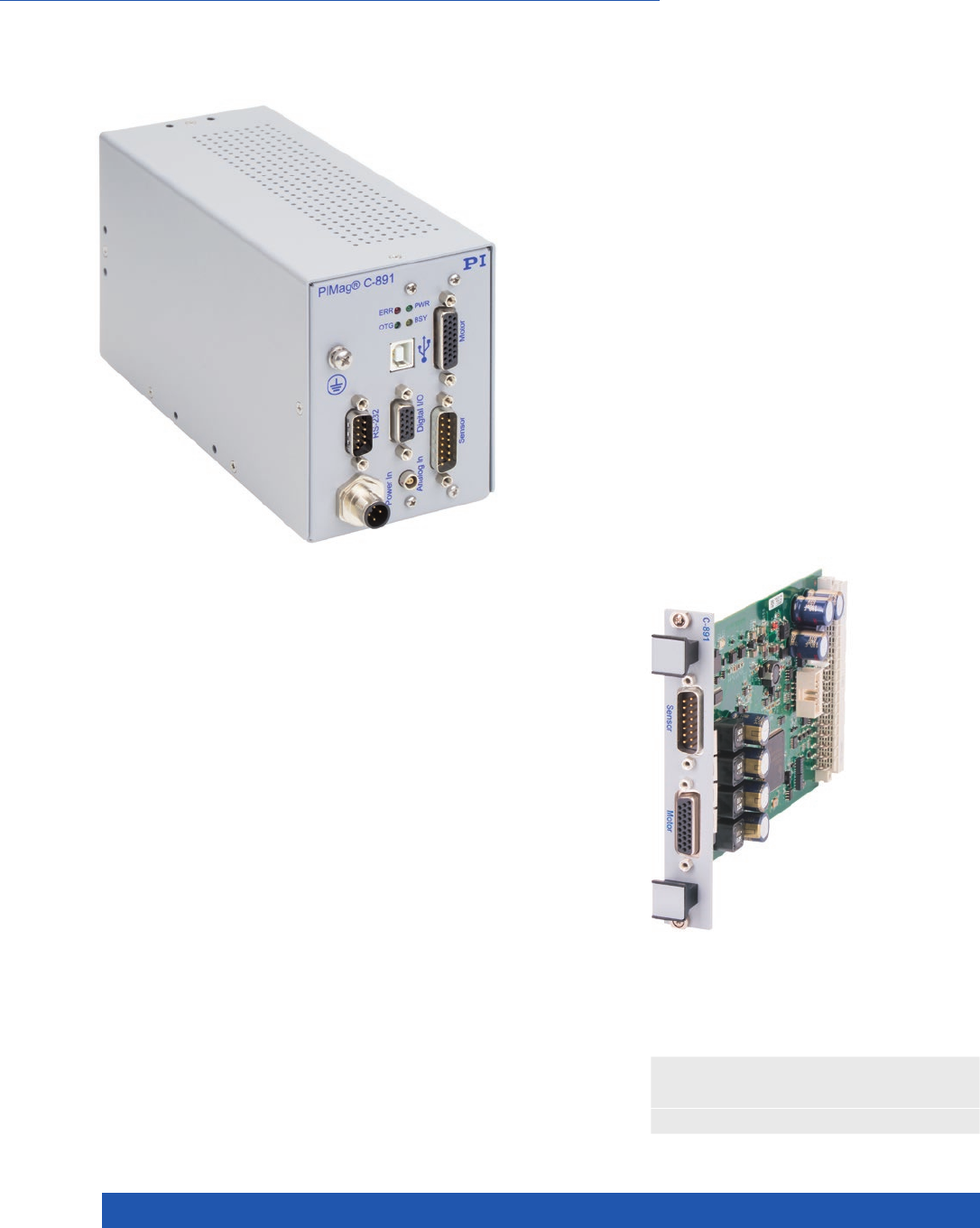
WWW.PI.WS
248
Digital motion controller for PIMag® linear motors
1 motor channel, 1 sensor channel. For three-phase linear
motors, maximum current consumption 3A (rms) per phase.
Sine-commutated operation, field-oriented current control. Auto-
matic detection of the motor phase. PID controller for position
and velocity. Servo update rate 20 kHz.
>> Extensive Software Package
Technology Glossary ...................... page 290
1 Axis, for 3-Phase Linear Motors with Medium Power Consumption
C-891 PIMag® Motion Controller
for Magnetic Direct Drives
n Maximum average current consumption 3 A
n 20-kHz control bandwidth
n USB interface for sending commands and for configuration
n Digital inputs and outputs
n Optional analog input
n Encoder inputs: A/B or sine/cosine and BiSS-C
C-891.10C885 Plug-in module
for C-885 PIMotionMaster

MOTION | POSITIONING
249
C-891.120200
Function PIMag® Motion Controller for 3-phase linear motors,
sine-commutated, field-oriented current control
Motor channels 1
Sensor channels 1
Supported functions Point-to-point motion. Data recorder. Wave generator.
Automatic detection of the motor phase.
Safety features Switch-off via external switch. Overload protection
of the motor driver. Overheat protection of the motor.
Overcurrent protection of the system.
Motion and control
Controller type PID controller for position and velocity, parameter changing
during operation
Servo frequency 20 kHz
Profile generator Trapezoidal velocity profile, setting of maximum velocity
and acceleration
Encoder input Analog (sin/cos) or digital signals (A/B differential, TTL,
or BISS interface)
Reference and limit switches TTL
Electrical properties
Max. output voltage 24 V
Max. output current 3 Arms
Interfaces and operation
Communication interfaces USB, RS-232
Motor connector HD Sub-D 26 (f)
Sensor connection Sub-D 15 (m)
I/O port 4 x digital input, 4 x digital output
Optional analog input, –10 to 10 V
Command set PI General Command Set (GCS)
User software PIMikroMove
Application programming
interfaces
API for C / C++ / C# / VB.NET / MATLAB / python, drivers
for LabVIEW
Miscellaneous
Operating voltage 24 V, external power supply included in the scope of delivery
Max. current consumption 4.5 A
Operating temperature range 5 to 40 °C
Max. mass 1.0 kg
Dimensions 190 mm × 83 mm × 110 mm
(with rubber feet and connection for supply voltage:
206 mm x 83 mm x 112 mm)
Ask about custom designs!
Motion Control
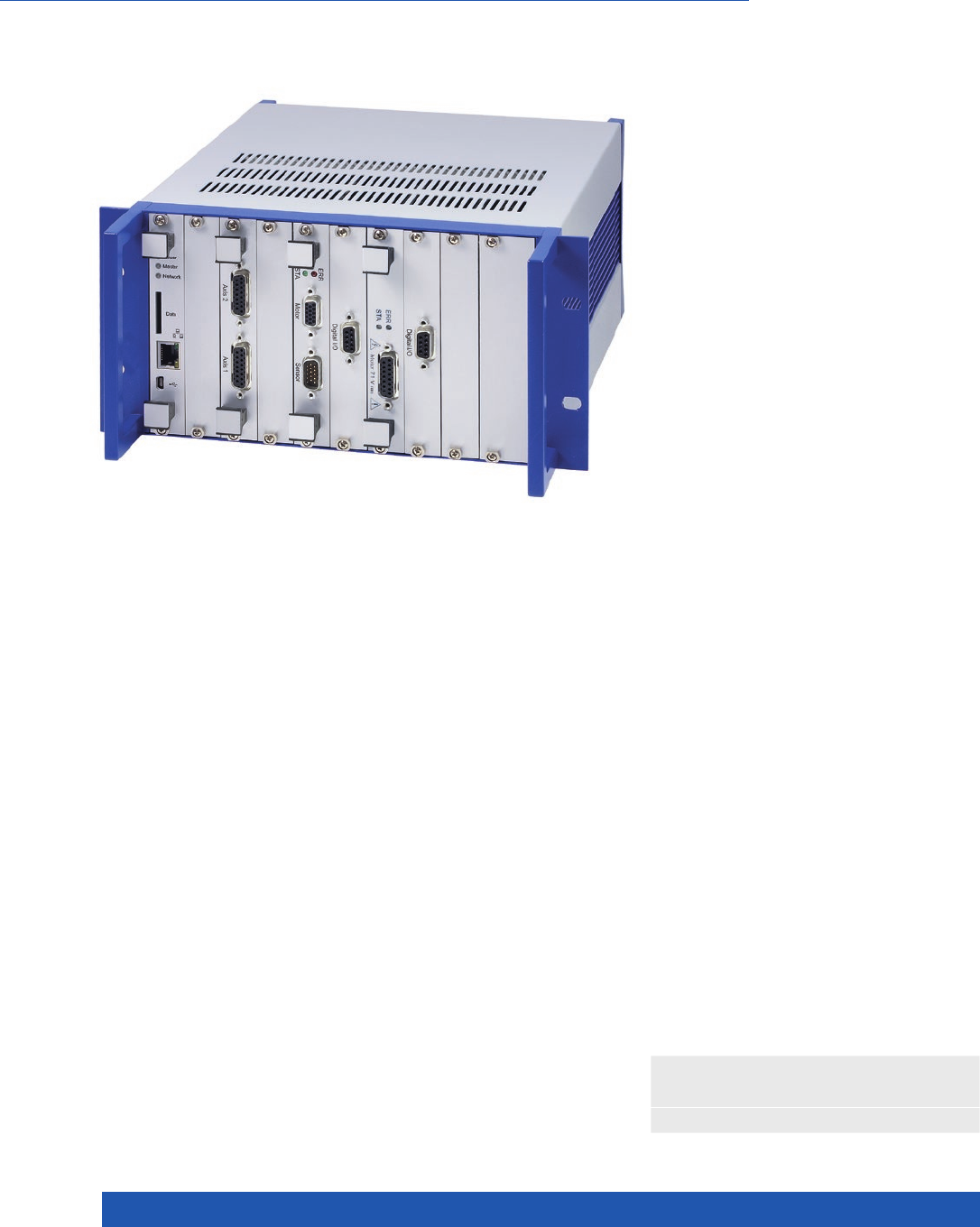
WWW.PI.WS
250
n Easy configuration and startup
n Modular design for versatile expansion
n Efficient communication with the controller modules
n Greatly reduced wiring effort
n Saves space and costs
Easy to expand
The system is easily scalable. An additional controller module
can be inserted into any free slot and expands the overall system
by the corresponding functions. Optional digital inputs and out-
puts can be installed for every controller module.
Controller modules
n C-863.20C885 DC Motor Controller Module, 2 Axes
n C-867.10C885 PILine® Controller Module
n E-861.11C885 NEXACT® Controller Module
n E-873.10C885 Q-Motion® Controller Module for
C-885 PIMotionMaster
n C-663.12C885 Mercury Step Stepper Motor Controller
Module
Easy installation
Plug-and-play installation of the controller modules in the C-885
PIMotionMaster. The processor and interface module commu-
nicates with the PIMikroMove software and with the controller
modules. It detects the available controller module type auto-
matically. Grouping the controller modules in one housing ensures
internal communication and reduces the wiring effort because
of the common power supply and external communication via a
single USB or Ethernet interface.
>> Extensive Software Package
Technology Glossary ...................... page 290
Rack with Processor and Interface Module for Modular Multi-Axis Controller System
C-885 PIMotionMaster

MOTION | POSITIONING
251
C-885.R1 C-885.R2 C-885.R3
Function 9.5” chassis for C-885
PIMotionMaster
19” chassis for C-885
PIMotionMaster
19” chassis for C-885
PIMotionMaster
Number of card slots 1 C-885.Mx module (required)
4 controller modules (max.)
1 C-885.Mx module (required)
20 controller modules (max.)
1 C-885.Mx module (required)
19 controller modules (max.)
Dimensions 269.04 mm × 133.14 mm ×
349.5 mm (incl. handles)
Without modules:
482.6 mm × 132.55 mm ×
265.3 mm
With modules:
482.6 mm × 132.55 mm ×
278.55 mm
Without modules:
482.6 mm × 132.55 mm ×
265.3 mm
With modules:
482.6 mm × 132.55 mm ×
278.55 mm
Operating voltage 24 V DC from external power
supply
24 V DC from external power
supply
24 V DC from external power
supply
also optional:
48 V DC from external power
supply
Supply voltage for controller
modules
24 V DC 24 V DC 24 V DC / 48 V DC
Current consumption, max. 32 A 32 A 32 A
Mass without modules 3.2 kg 2.9 kg 5.08 kg
Operating temperature range 10 to 40 °C 10 to 40 °C 10 to 40 °C
C-885.M1 C-885.M2
Function Digital Processor and Interface Module
for C-885 PIMotionMaster
Digital Processor and Interface Module
for C-885 PIMotionMaster
Communication interfaces Ethernet, USB Ethernet, USB
Command set PI General Command Set (GCS) PI General Command Set (GCS)
User software PIMikroMove PIMikroMove
Software drivers LabVIEW drivers, dynamic libraries
for Windows and Linux
LabVIEW drivers, dynamic libraries
for Windows and Linux
Indicators LEDs for Power, Error LEDs for Power, Error
Operating temperature range 10 to 40°C 10 to 40°C
Mass 132 g 270 g
Dimensions 186.42 mm × 128.4 mm (3 RU) × 19.98 mm
(4 HP)
186.42 mm × 128.4 mm (3 RU) × 19.98 mm
(4 HP)
Ask about custom designs!
Motion Control
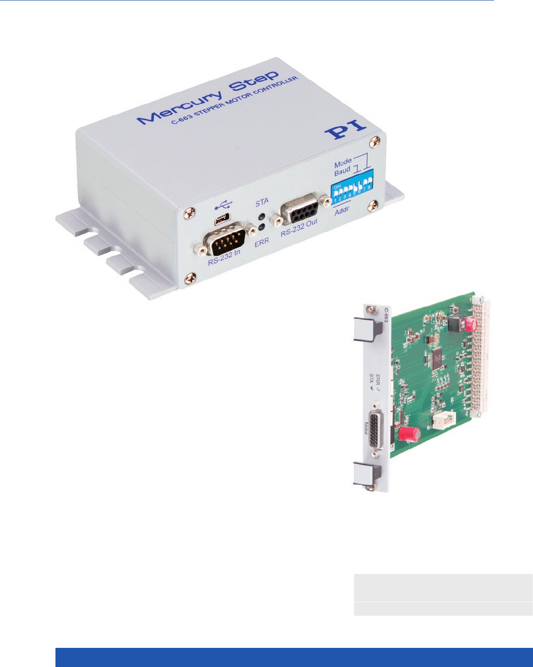
WWW.PI.WS
252
C-663.12C885 Mercury Step Stepper
Motor Controller Plug-in Module for
C-885 PIMotionMaster
For Closed-Loop and Open-Loop Operation, HD Sub-D 26, 48 V
n High microstep resolution
n Operating voltage up to 48 V
n Closed-loop operation of 2-phase stepper motors
n Support for external sensors
n Daisy chain networking
C-663.12
Mercury Step Stepper Motor Controller, 1 Axis
>> Extensive Software Package
Technology Glossary ...................... page 290

MOTION | POSITIONING
253
C-663.12
Function Mercury Step stepper motor controller
Drive types 2-phase stepper motor
Axes 1
Supported functions Point-to-point motion. Startup macro.
Data recorder for recording operating data such as velocity,
position or position error.
Internal safety circuitry: Watchdog timer.
ID chip detection (for future use).
Motion and control
Controller type PID, parameter changing during operation
Servo cycle time 50 µs
Dynamics profile Trapezoidal velocity profile
Microstep resolution 1/2048 full step
Encoder input A/B quadrature, TTL, RS-422; 60 MHz
Limit switches 2 × TTL, programmable
Reference point switch 1 × TTL, programmable
Index switch 1 × RS-422 for index pulse
Stall detection Automatic motor stop when a programmable position error
is exceeded (only in conjunction with sensor)
Electrical properties
Max. output voltage* 0 V to operating voltage, for direct control of stepper motors
Max. output power 60 W
Average output power 48 W
Power consumption, full load 48 W (max.)
Power consumption without load 3 W
Current limitation per motor phase 2.5 A
Interfaces and operation
Communication interfaces USB, RS-232
Motor / sensor connection HD Sub-D 26 (f)
Controller network Up to 16 units on a single interface**
I/O lines 4 analog / digital inputs (0 to 5 V / TTL), 4 digital outputs (TTL)
Command set PI General Command Set (GCS)
User software PIMikroMove
Application programming interfaces API for C / C++ / C# / VB.NET / MATLAB / python,
drivers for LabVIEW
Manual control Joystick, Y-cable for 2-D motion, pushbutton box
Miscellaneous
Operating voltage 24 to 48 V DC from external power supply
(48 V DC power supply in scope of delivery)
Max. current consumption 40 mA without load (when supplied with 48 V)
80 mA without load (when supplied with 24 V)
Operating temperature range 5 to 50 °C (temperature protection switches off at excessively
high temperatures)
Mass 0.48 kg
Dimensions 130 mm × 76 mm × 40 mm (incl. mounting rails)
* Depending on the power supply used
** 16 units with USB; 6 units with RS-232
Motion Control
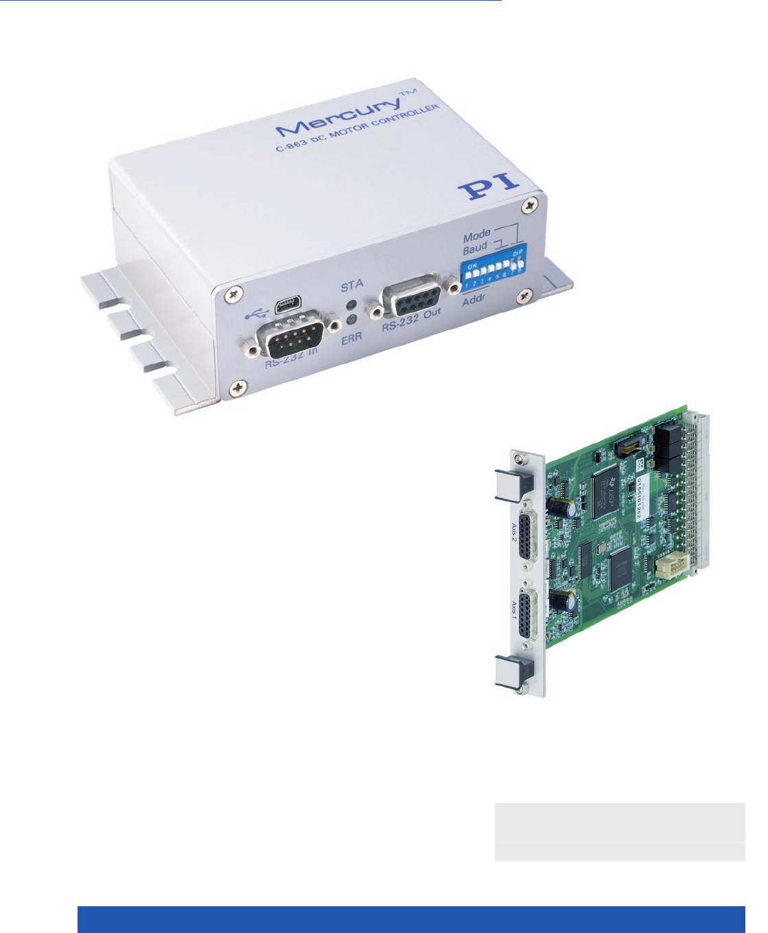
WWW.PI.WS
254
C-863.20C885 2-Axes DC Motor
Controller, Plug-in Module for C-885
PIMotionMaster
1 Axis, for DC Motors and Brushless DC Motors
n High-speed encoder input to 60 MHz
n Powerful macro programming language,
e.g., for stand-alone operation
n Nonvolatile EEPROM for macros and parameters
n Data recorder
n Daisy chain networking
n Connection for joystick
C-863 Mercury Servo Controller
>> Extensive Software Package
Technology Glossary ...................... page 290

MOTION | POSITIONING
255
C-863.11 / C-863.12
Function DC motor control, servo control
Axes 1
Supported functions Point-to-point motion. Startup macro. Data recorder for recording operating data such as
motor voltage, velocity, position or position error. Internal safety circuitry: Watchdog timer.
C-863.12 additional: ID chip detection
Motion and control
Controller type PID controller, parameter changing during operation
Servo cycle time 50 µs
Profile generator Trapezoidal velocity profile
Encoder input A/B quadrature single-ended or differential TTL signal acc. to RS-422; 60 MHz
Stall detection Automatic motor stop when a programmable position error is exceeded
Limit switches 2 × TTL (programmable polarity)
Reference point switch 1 × TTL
Motor brake 1 × TTL, can be switched by software
Interfaces and operation
Communication interfaces USB; RS-232, Sub-D 9 (m)
Motor connection C-863.11: Sub-D 15 (f) / C-863.12: HD Sub-D 26 (f)
Controller network Up to 16 units** on a single interface
I/O lines 4 analog / digital inputs, 4 digital outputs (TTL), 5 V TTL
Command set PI General Command Set (GCS)
User software PIMikroMove
Application programming
interfaces
API for C / C++ / C# / VB.NET / MATLAB / python, drivers for LabVIEW
Manual control Joystick, Y cable for 2-D motion, pushbutton box
C-863.11 C-863.12
Electrical properties
Max. output voltage* 0 to ±15 V for direct control of DC motors 0 V to operating voltage,
for direct control of DC motors
Max. output power 30 W 60 W
Average output power 45 W 48 W
Power consumption, full load 30 W 48 W
Power consumption without load 2 W 3 W
Current limitation 2 A 2.5 A
Miscellaneous
Operating voltage 15 to 30 V from external power supply
(15 V DC power supply in scope of delivery)
24 to 48 V DC from external power supply
(48 V DC power supply in scope of delivery)
Max. current consumption 80 mA without load
(when supplied with 24 V)
40 mA without load
(when supplied with 48 V)
80 mA without load
(when supplied with 24 V)
Operating temperature range 5 to 50 °C 5 to 50 °C (temperature protection switches
off at excessively high temperatures)
Mass 0.3 kg 0.48 kg
Dimensions 130 mm × 76 mm × 40 mm
(incl. mounting rails)
130 mm × 76 mm × 40 mm
(incl. mounting rails)
Motion Control
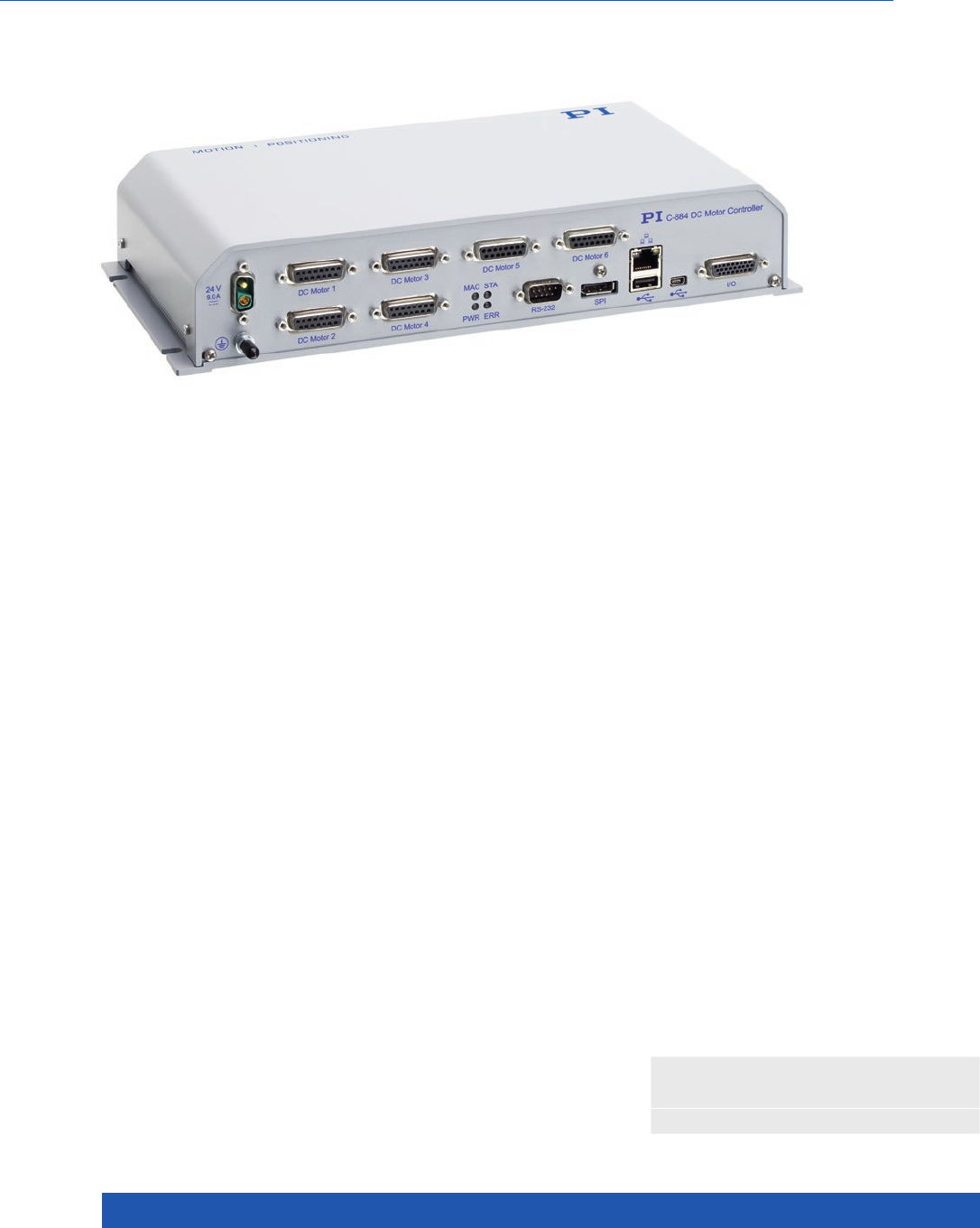
WWW.PI.WS
256
n PID servo control with dynamic parameter switching
n Powerful macro programming language, e.g., for
stand-alone operation
n Data recorder
n Integrated interfaces: USB, RS-232, Ethernet, SPI, I/O,
joystick
n Trajectory support for 1 or 2 D motion patterns
Motion profiles
Point-to-point, trapezoidal velocity profile. User-definable trajec-
tories (e.g., circles, sine curves) from externally fed points.
Interfaces and communication
Interfaces: TCP/IP, USB and RS-232 for commands. A/B quad-
rature encoder input. TTL inputs for limit and reference point
switches. I/O lines (analog/digital) for automation. USB interface
for human interface devices.
Extensive functions, software support
Powerful macro command language. Nonvolatile macro storage,
e.g., for stand-alone operation with autostart macro. Data recor-
der. ID chip detection for fast startup. PID controller, parameter
changing during operation. Extensive software support, e.g., for
LabVIEW, C, C++, MATLAB, python. PIMikroMove user software.
Digital motion controller for DC servo motors
4 or 6 axes. Dual-core architecture for increased performance
and flexibility by separating command processing and position
control. Simple adaptation / extension possible for OEM pro-
ducts. Motion control of PI positioning systems with DC motors:
Direct motor control, PWM control for PI positioning stages with
integrated ActiveDrive amplifiers or integrated block commu-
tation (brushless motors). Supports motor brake.
For Positioners with Closed-Loop DC Motor, USB, RS-232, TCP/IP, SPI, I/O, Joystick
C-884.4DC / C-884.6DC
Motion Controller for DC Motors, 4 or 6 Axes
>> Extensive Software Package
Technology Glossary ...................... page 290

MOTION | POSITIONING
257
C-884.4DC / C-884.6DC
Function Position control for closed-loop DC motors
Processor Dual core architecture. Controller on a DSP core, with
extendable command interpreter in an ARM core under Linux
Axes C-884.4DC: 4 / C-884.6DC: 6
Supported functions Linear vector motion. Point-to-point motion.
User-definable trajectories.
Startup macro. PI Python. Data recorder for recording operating
data such as motor voltage, velocity, position or position error.
ID chip detection.
Motion and control
Controller type PID controller, parameter changing during operation
Servo cycle time 100 µs
Profile generator Trapezoidal velocity profile
Encoder input A/B quadrature (TTL differential according to RS-422), 50 MHz;
BiSS interface
Stall detection Automatic motor stop when a programmable position error
is exceeded
Limit switches 2 × TTL per axis (programmable polarity)
Reference point switch 1 × TTL per axis
Motor brake 1 × TTL per axis, can be switched per software
Electrical properties
Max. output voltage* 24 V
Max. output power 240 W
Current limitation 2.5 A per axis
Interfaces and operation
Communication interfaces TCP/IP: RJ45 / Ethernet; USB: Mini-USB type B;
RS-232: Sub-D 9 (m); SPI: DisplayPort
Motor connector Sub-D 15 (f)
I/O lines 4 analog inputs (–10 to 10 V), 4 digital outputs (5 V TTL)
4 digital outputs (5 V TTL)
Command set PI General Command Set (GCS)
User software PIMikroMove
Application programming interfaces API for C / C++ / C# / VB.NET / MATLAB / python,
drivers for LabVIEW
Manual control USB interface for HID-compliant devices
Miscellaneous
Operating voltage External power supply 24 V / 5 A (120 W) included in the scope
of delivery
Max. current consumption C-884.4DC: 11 A / C-884.6DC: 16 A
Current consumption, no load 500 mA
Operating temperature range 5 to 50 °C
Mass C-884.4DC: 1.77 kg / C-884.6DC: 1.97 kg
Dimensions 312 mm × 153.4 mm × 59.2 mm (incl. mounting rails)
* The output voltage depends on the connected power supply.
Motion Control
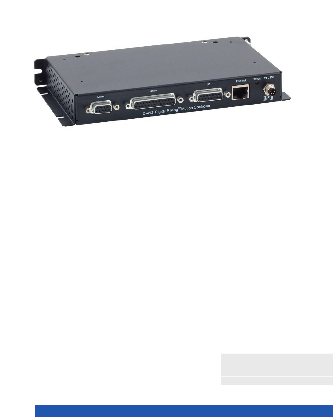
WWW.PI.WS
258
n 1 or 2 motor channels
n Up to 4 sensor channels for 2 force and
2 position sensors each
n Depending on version, TCP/IP or USB
interface for configuration and sending
commands
n Depending on version, real-time SPI
interface for sending commands
n Digital inputs and outputs
n Optional analog inputs and outputs
Digital motion controller for PIMag® voice coil drives
C-413.1: 1 motor channel, 2 sensor channels, for the V-275 and V-277 linear
actuators; C-413.2: 2 motor channels, 4 sensor channels. PID controller for force,
position, velocity. Servo update rate selectable between 5 to 10 kHz.
Force control
The force control allows operation of PIMag® drives and stages with a defined
holding or feed force. The force and position sensors can be read simultaneous-
ly and the values processed. In addition to pure force control, subordinate
position and velocity control is also an option. PI offers PIMag® actuators with
a force sensor. The C-413.20A / .2GA models enable external force sensors
to be read via analog inputs.
Extensive functionality
Data recorder: Recording of operating data such as motor current, velocity,
position or position error. Wave generator: Saves and outputs periodical
motion profiles. Auto-zero function defines the holding current, at which
the drive outputs a force of 0 N in open-loop operation, e.g., for compensat-
ing the weight force. ID chip support: Identifies the connected stages and
simplifies configuration and exchangeability. Supports direction-sensing ref-
erence point switches. Extensive software support, e.g., for LabVIEW, dynamic
libraries for Windows and Linux.
Interfaces
Depending on the version, commanding via TCP/IP, USB 2.0, SPI. Digital inputs
and outputs for automation. Optional analog inputs and outputs, e.g., for
sensors, commanding or position feedback.
Control of Force, Position and Velocity
C-413 PIMag® Motion Controller
>> Extensive Software Package
>> PIMag® Voice Coil
Technology Glossary ...................... page 290

MOTION | POSITIONING
259
Ask about custom designs!
C-413.1G C-413.20 / C-413.20A
C-413.2G / C-413.2GA
Function PIMag® motion controller for voice coil drives,
1 channel, housed device
PIMag® motion controller for voice coil drives,
2 channels
C-413.20/.20A: OEM board
C-413.2G/.2GA: Housed device
Motor channels 1 2
Sensor channels 2 4
Motion and control
Servo characteristics PID controller for force, position and velocity;
parameter changing during operation
PID controller for force, position and velocity;
parameter changing during operation
Servo cycle time 100 µs to 200 µs, selectable in 4 steps 100 µs to 200 µs, selectable in 4 steps
Profile generator Trapezoidal velocity profile, specification of the
maximum velocity and acceleration
Trapezoidal velocity profile, specification of the
maximum velocity and acceleration
Encoder input SPI sensor interface SPI sensor interface
Reference point switches 2 × TTL, direction-sensing 4 × TTL, direction-sensing
Electrical properties
Max. output voltage 24 V 24 V
Max. output current ±1.5 A (regulated) ±1.5 A (regulated)
Interfaces and operation
Communication interfaces TCP/IP USB 2.0, real time SPI
Motor / sensor connection Sub-D 9 (f) for motor, Sub-D 25 (f) for sensor Sub-D 15 (f) combined for motor and sensor
I/O port 2 × analog output, –10 to 10 V, 17 bit, 1 kHz
4 × digital input, 24 V
6 × digital output, 24 V
2 × analog input, –10 to 10 V, 16 bit, 1 kHz
(only .20A and .2GA)
2 × analog output, –10 to 10 V, 17 bit, 1 kHz
(only .20A und .2GA)
6 × digital outputs (open collector, voltage
range 5 V to 24 V, 33 kΩ internal pull-up to 5 V)
4 × digital input (5 V TTL level, to 24 V max.
input voltage, 10 kΩ input resistance)
Command set PI General Command Set (GCS) PI General Command Set (GCS)
User software PIMikroMove PIMikroMove
Application programming
interfaces
API for C / C++ / C# / VB.NET / MATLAB / python,
drivers for LabVIEW
API for C / C++ / C# / VB.NET / MATLAB /
python, drivers for LabVIEW
Supported functions Point-to-point motion. Data recorder. Wave
generator. Auto zero. ID chip detection.
Point-to-point motion. Data recorder. Wave
generator. Auto zero. ID chip detection.
Miscellaneous
Operating voltage 24 V DC from external power supply (included) 24 V DC from external power adapter (included
in the scope of delivery for C-413.2G and .2GA)
Max. current consumption 2 A 2 A
Operating temperature range 5 to 50 °C 5 to 50 °C
Mass 0.3 kg 0.3 kg
Dimensions 210 mm × 28 mm × 105 mm 189 mm × 28 mm × 105 mm (.2G/.2GA)
160 mm × 18 mm × 100 mm (.20/.20A)
Motion Control
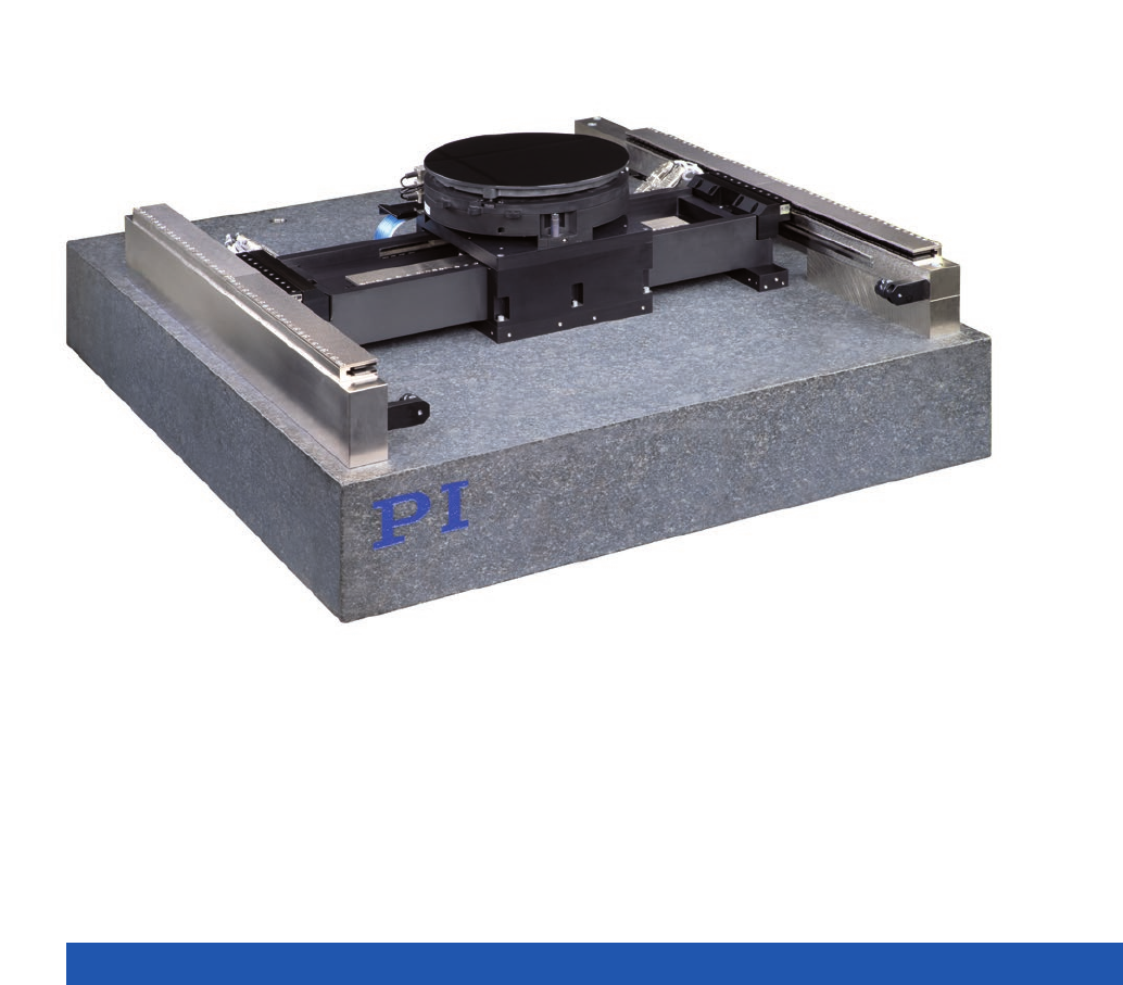
WWW.PI.WS
260
Gantry Systems

MOTION | POSITIONING
261
Gantry Systems ....................................................................................................................................................................... 262
Throughput, Precision and Reliability ........................................................................... 262
Gantry Systems
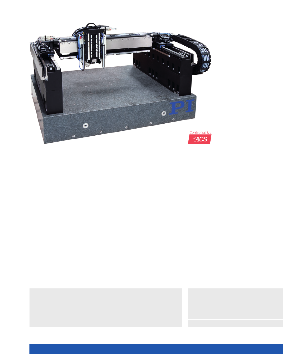
WWW.PI.WS
262
Gantry Systems – High-Dynamic Precision
Positioning in 3 Axes
n Linear motor or brushless drives, optionally
with air bearings
n Individual travel ranges in XY up to 2 m
n Z-axis with pneumatic counterweight,
DC or Stepper motor
n Piezomotor for fine adjustment
n Incremental or absolute encoders
n Controlled by ACS Motion Control
The specifications below are an example of
what is feasible. Contact PI to discuss your
requirements!
XY and Gantry Systems from PI
Positioning and motion tasks in industrial automation such as those in assem-
bly, semiconductor manufacturing, mechanical engineering, laser material pro-
cessing, inspection systems or in additive manufacturing demand solutions that
need to be robust and reliable.
PI offers a broad range of in-house drive and motion control technologies such
as EtherCAT-based industrial controllers by ACS, where PI holds the major
shares, or air bearing technology for optimized guiding accuracy. System
engineering for customization and a global service and training network are
added-value offers. PI is therefore the ideal partner for motion-centric industrial
solutions.
>> Absolute Encoder
>> Air Bearing
>> Linear Motor
Technology Glossary ...................... page 290
Applications
n Electronics Manufacturing
n Laser Cutting
n Sample Inspection
Solutions for Motion-Centric Industrial Automation
Throughput, Precision and Reliability

MOTION | POSITIONING
263
Unit Tolerance
Active axes X Y Z
Motion and positioning
Travel range 508 508 155 mm
Integrated sensor Optical linear
encoder, incremental
Optical linear
encoder, incremental
Optical linear
encoder, incremental
Sensor resolution 0.002 0.002 0.002 µm
Unidirectional repeatability 0.5 0.5 0.5 µm typ.
Max. velocity*3000 3000 2000 mm/s typ.
Max. acceleration** 30 30 20 m/s2typ.
Mechanical properties
Bearings Ball bearing Ball bearing Cross roller bearings
Load capacity 5 kg max.
Motor type Ironless
linear motor
Ironless
linear motor
Ironless linear motor
with pneumatic
counterbalance
* Maximum speed based on stage capability. Maximum application velocity may be limited by system data rate and system resolution.
Maximum speed of the z-axis is specified without pneumatic counterbalance.
** No load. Maximum acceleration of the z-axis is specified without pneumatic counterbalance.
Gantry Systems
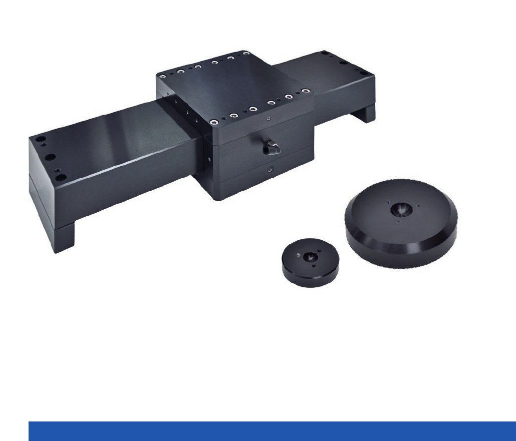
WWW.PI.WS
264
Components & Accessories

MOTION | POSITIONING
265
Air Bearings .............................................................................................................................................................................. 266
A-10x PIglide RB Linear Air Bearing Module ................................................................. 266
A-10x.MNT Mounting Feet ............................................................................................. 269
A-41x PIglide FPC: Flat, Circular Air Bearing Modules ................................................... 270
A-60x PIglide RT Rotary Air Bearing Module ................................................................. 274
A-65x PIglide HB: Hemispherical Air Bearing ................................................................ 278
Accessories for Air Bearings and Stages ................................................................................................................................. 280
A-60x.MTT PIglide Manual X-Y-Tilt Platform .................................................................. 280
A-80x PIglide Filter and Air Preparation Kits .................................................................. 282
Adapter Brackets for Multi-Axis Combinations ...................................................................................................................... 286
L-500 Adapter Bracket ................................................................................................... 286
Components &
Accessories
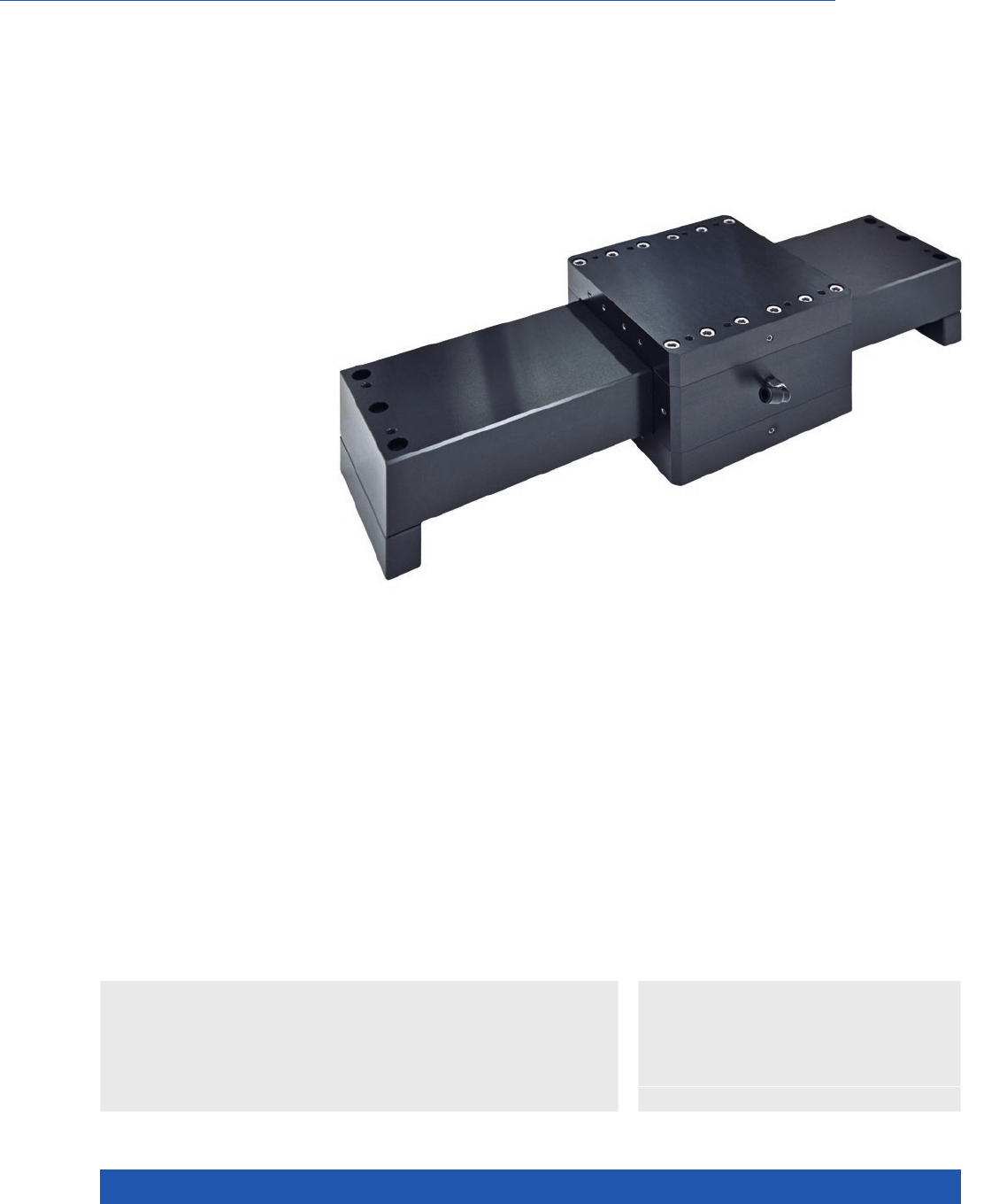
WWW.PI.WS
266
Friction Free, Ideal for Positioning, Scanning, Metrology
A-10x PIglide RB Linear Air Bearing Module
>> PIglide Air Bearing Technology
Technology Glossary ...................... page 290
Applications
n Sample Inspection
n Scanning
n Metrology / Testing
n Optical Alignment
n Flatpanel Inspection
n Ideal for scanning applications or high-resolution positioning
n Cleanroom compatible
n Size of the motion platform to 300 mm × 300 mm
n Travel ranges to 1 m
n Load capacity to 775 kg
n Straightness / flatness to 0.5 µm per 25 mm
n Pitch / roll / yaw to 1.2 µrad per 25 mm
Accessories and options
n Air preparation kit
n Mounting Feet
n Custom configurations on request
n Several motion platforms on one guide
n Constructions with moving guide
Linear air bearings of the PIglide RB series are exactly right for applications that
need smooth, precise, linear motion. The air bearing modules replace ball or
crossed roller guides and are easy to integrate. They offer improved straight-
ness, angular deviation, and repeatability compared to stage units with ball
guides, especially for travel ranges longer than 100 mm.
Because air bearings are basically friction free, they work without stiction on
approach or during operation, even under maximum load. Air bearings work
without making contact and with purified air, and are virtually maintenance
and wear free.

MOTION | POSITIONING
267
* The specified load capacities assume an operating pressure of 80 psi (550 kPa).
For an alternative operating pressure, contact PI for determining other load capacities.
** Precision specifications depending on load, orientation, and external forces on the bearing.
Contact PI for application-specific parameters.
Ask about custom designs!
Size of the motion
platform / mm × mm
Travel range / mm Vertical load
capacity* / N
Lateral load
capacity* / N
A-101 50 × 50 50 to 200 130 75
A-102 50 × 100 50 to 300 260 260
A-103 75 × 75 50 to 300 350 195
A-104 75 × 115 50 to 300 540 540
A-105 100 × 100 50 to 300 630 370
A-106 100 × 150 50 to 600 950 950
A-107 150 × 150 50 to 750 1580 790
A-108 200 × 200 50 to 1000 2950 1475
A-109 300 × 300 50 to 1000 7600 2210
Travel ranges
to 300 mm
Travel ranges
to 600 mm
Travel ranges
to 1000 mm
Straightness / flatness** ±1.25 µm ±2.5 µm ±5 µm
Straightness / flatness,
per 25 mm travel
range**
±0.25 µm ±0.25 µm ±0.25 µm
Position stability** ±0.05 µm ±0.05 µm ±0.05 µm
Pitch / yaw, per 25 mm
travel range**
1.2 µrad 1.2 µrad 1.2 µrad
Pitch / yaw, overall** 10 µrad 20 µrad 30 µrad
A-10x.xxx
Operating pressure 80 psi (550 kPa) nominal
Air consumption <1.0 SCFM (28 SLPM)
Air quality Clean (filtered to 1.0 µm or better) – ISO 8573-1 Class 1
Oil free – ISO 8573-1 Class 1
Dry (–15 °C dew point) – ISO 8573-1 Class 3
Materials Hardcoat aluminum, stainless steel fasteners
Components &
Accessories
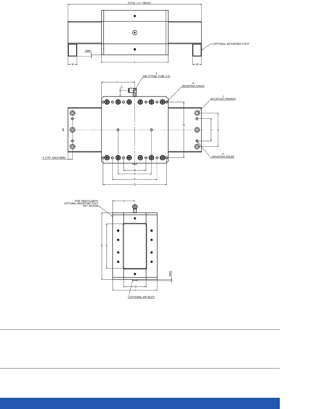
WWW.PI.WS
268
Model A B C D E F G H J K L M N P Q R S T U V W X
A-101
A-102
A-103
A-104
A-105
A-106
A-107
A-108
A-109
50
100
75
115
100
150
150
200
300
50
50
75
75
100
100
150
200
300
35
45
55
75
75
100
100
130
140
15
25
25
45
35
60
50
70
70
25
25
45
45
60
60
100
140
240
5
5
7.5
7.5
10
10
10
10
10
15
15
30
30
40
40
75
100
200
CL
CL
12.5
12.5
20
20
50
50
100
4x M3 C’BORE
4x M3 C’BORE
4x M5 C’BORE
4x M5 C’BORE
4x M6 C’BORE
4x M6 C’BORE
6x M6 C’BORE
6x M6 C’BORE
6x M6 C’BORE
2x M3
2x M3
2x M5
2x M5
2x M6
2x M6
4x M6
4x M6
4x M3
80
130
115
155
150
200
200
250
350
15
15
35
50
50
50
50
50
50
40
40
N/A
N/A
N/A
N/A
N/A
N/A
N/A
N/A
60
N/A
N/A
N/A
110
110
150
150
N/A
N/A
N/A
N/A
N/A
N/A
N/A
N/A
250
40
40
60
60
80
80
125
170
270
6x M3
10x M3
4x M5
4x M5
4x M6
8x M6
8x M6
8x M6
12x M6
12
12
14
14
14
14
14
14
14
21
46
37.5
57.5
50
75
75
100
150
30
40
47.5
67. 5
37.5
50
50
65
65
10
10
15
15
20
20
20
20
20
4 (5/32”)
6 (1/4”)
6 (1/4”)
6 (1/4”)
6 (1/4”)
6 (1/4”)
6 (1/4”)
6 (1/4”)
6 (1/4”)
A-10x.xxx, dimensions in mm
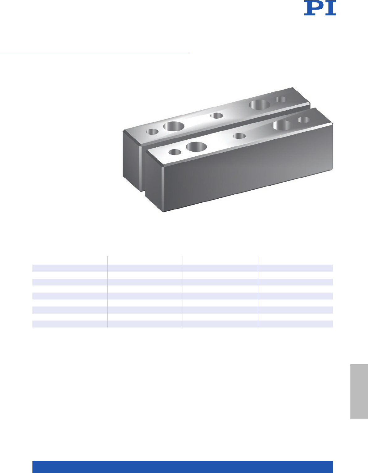
MOTION | POSITIONING
269
For Mounting the Air Bearing Modules of the A-10x Series
A-10x.MNT Mounting Feet
n Hardcoat aluminum
n Matched exactly to the respective
air bearing module
Model Compatible with Width / mm Overall mass (one set) / kg
A-101.MNT A-101.xxx 10 0.03
A-102.MNT A-102.xxx 10 0.03
A-103.MNT A-103.xxx 15 0.08
A-104.MNT A-104.xxx 15 0.08
A-105.MNT A-105.xxx 20 0.13
A-106.MNT A-106.xxx 20 0.13
A-107.MNT A-107.xxx 20 0.27
A-108.MNT A-108.xxx 20 0.46
A-109.MNT A-109.xxx 20 0.94
Components &
Accessories
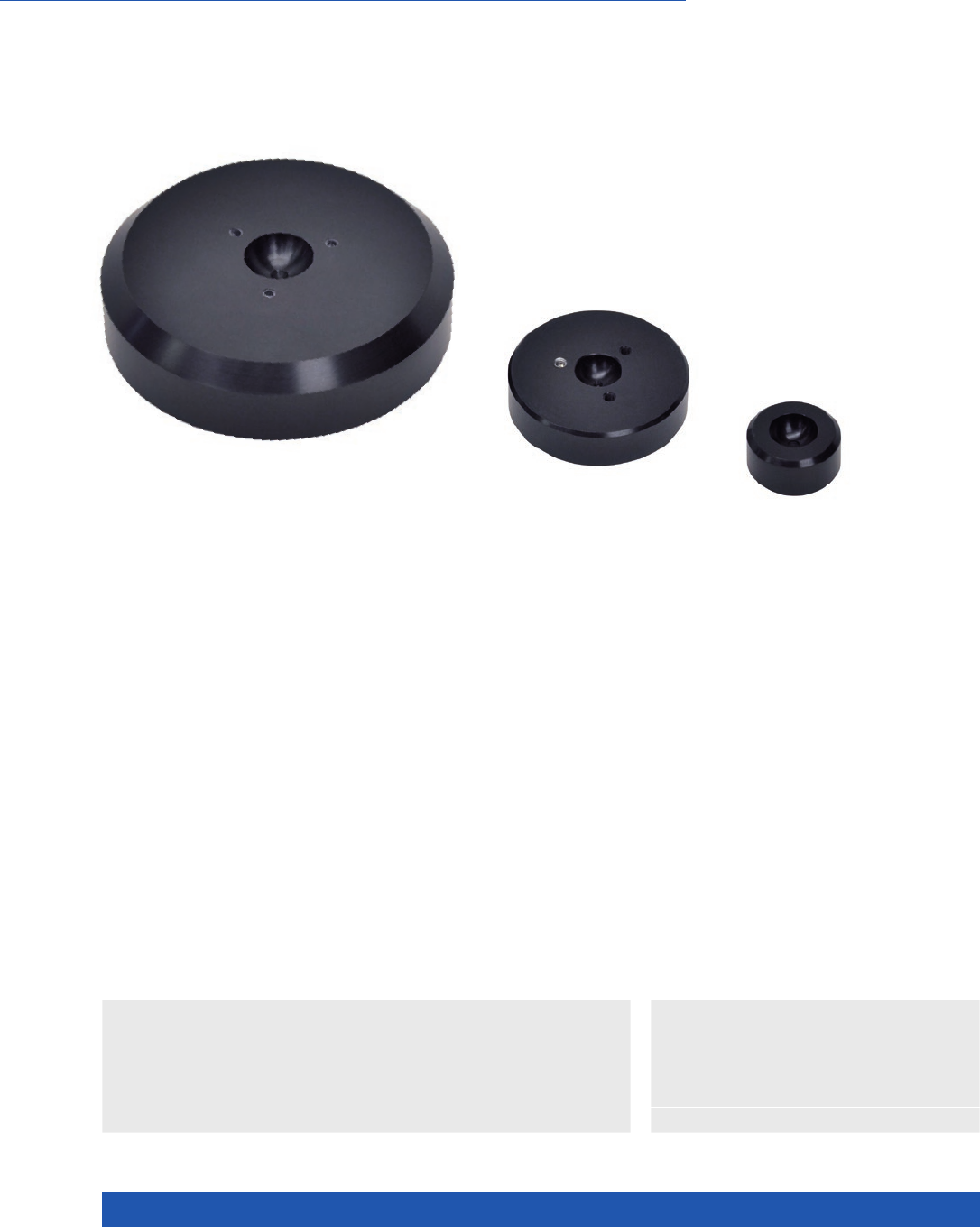
WWW.PI.WS
270
Friction-free, modular air bearings
A-41x PIglide FPC:
Flat, Circular Air Bearing Modules
>> PIglide Air Bearing Technology
Technology Glossary ...................... page 290
Applications
n Sample Inspection
n Scanning
n Metrology / Testing
n Optical Alignment
n Flatpanel Inspection
n Diameters from 25 mm to 300 mm
n Load capacity to 15500 N
n Stiffness to 860 kN/mm
n Cleanroom compatible
n Mounting hardware, customizations,
and accessories available
The PIglide Flat Pad Circular air bearing series is suitable for applications that
require friction-free, accurate linear or planar motion. The modular concept of
these air bearings allows the user to build their own motion system. Several
bearings can be combined to increase the load capacity or to create multi-axis
motion platforms.

MOTION | POSITIONING
271
The loads listed assume a supply pressure of 550 kPa (80 psi). Please contact PI if other pressures are required.
Part # Diameter / mm Ball interface
diameter / mm
Load
capacity / N
Stiffness /
N/µm
Air
consumption /
l/h (SCFH)
Mass / g
A-411.025 25 13 88 1 7. 5 60 (2) 16
A-411.040 40 13 220 28.0 60 (2) 42
A-411.050 50 13 330 52.5 85 (3) 66
A-411.065 65 13 660 78.8 115 (4) 171
A-411.080 80 13 1010 111 170 (6) 259
A-411.100 100 20 1710 175 170 (6) 505
A-411.125 125 20 2780 254 230 (8) 110 5
A-411.150 150 20 4000 350 285 (10) 1590
A-411.200 200 20 7700 520 570 (20) 4040
A-411.300 300 20 15500 860 850 (30) 12000
Air supply
Operating pressure 80 psi (550 kPa) nominal
Air quality Clean (filtered to 1.0 µm or better) – ISO 8573-1 Class 1
Oil free – ISO 8573-1 Class 1
Dry (–15 °C dew point) – ISO 8573-1 Class 3
Miscellaneous
Guideway surface flatness <1µm / 300 mm
Nominal fly-height 10 – 15 µm
Materials Hardcoat aluminum, stainless steel fasteners
Recommended
guideway materials
Guideways are supplied by the customer.
Granite, hardcoat aluminum, stainless steel,
ceramics, nickel-plated steel, nickel-plated cast iron
Air bearing type Discrete orifice
Mounting Hardware
(sold separately)
Part # Description Ball interface diameter
A-412.013S Threaded ball stud
assembly
13
A-412.013N Mounting nut 13
A-412.013P Retaining plate 13
A-412.020S Threaded ball stud
assembly
20
A-412.020N Mounting nut 20
A-412.020P Retaining plate 20
Components &
Accessories
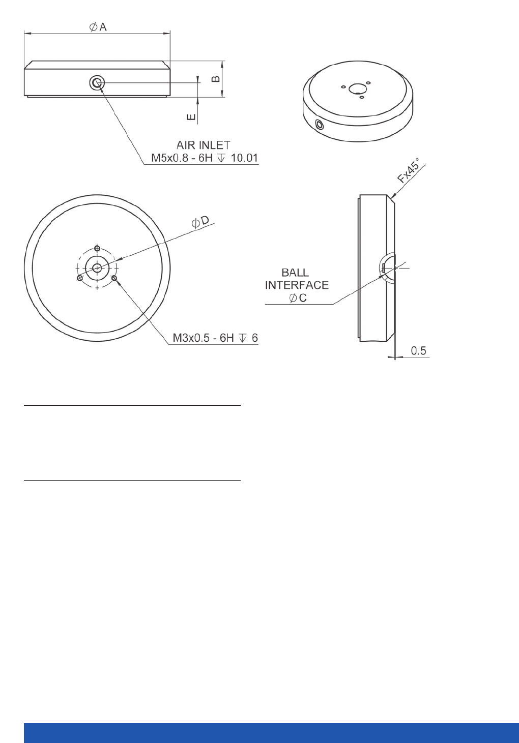
WWW.PI.WS
272
Model A B C D E F
A- 411.025
A- 411.0 4 0
A- 411.0 50
A- 411.0 6 5
A- 411.0 8 0
A- 411.100
A- 411.125
A- 411.150
A- 411.20 0
A-411.300
25
40
50
65
80
100
125
150
200
300
13
13
13
20
20
25
35
35
66
66
13
13
13
13
13
20
20
20
20
20
N/A
21.6
21.6
21.6
21.6
31.6
31.6
31.6
31.6
31.6
6.4
7
7
8
8
9
9
9
9
9
1.5
1
1
1
4.5
6.4
6.4
6.4
25
25
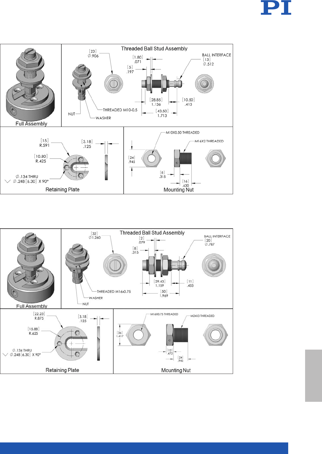
MOTION | POSITIONING
273
Mounting hardware dimensions: 13 mm ball interface diameter
Mounting hardware dimensions: 20 mm ball interface diameter
Components &
Accessories
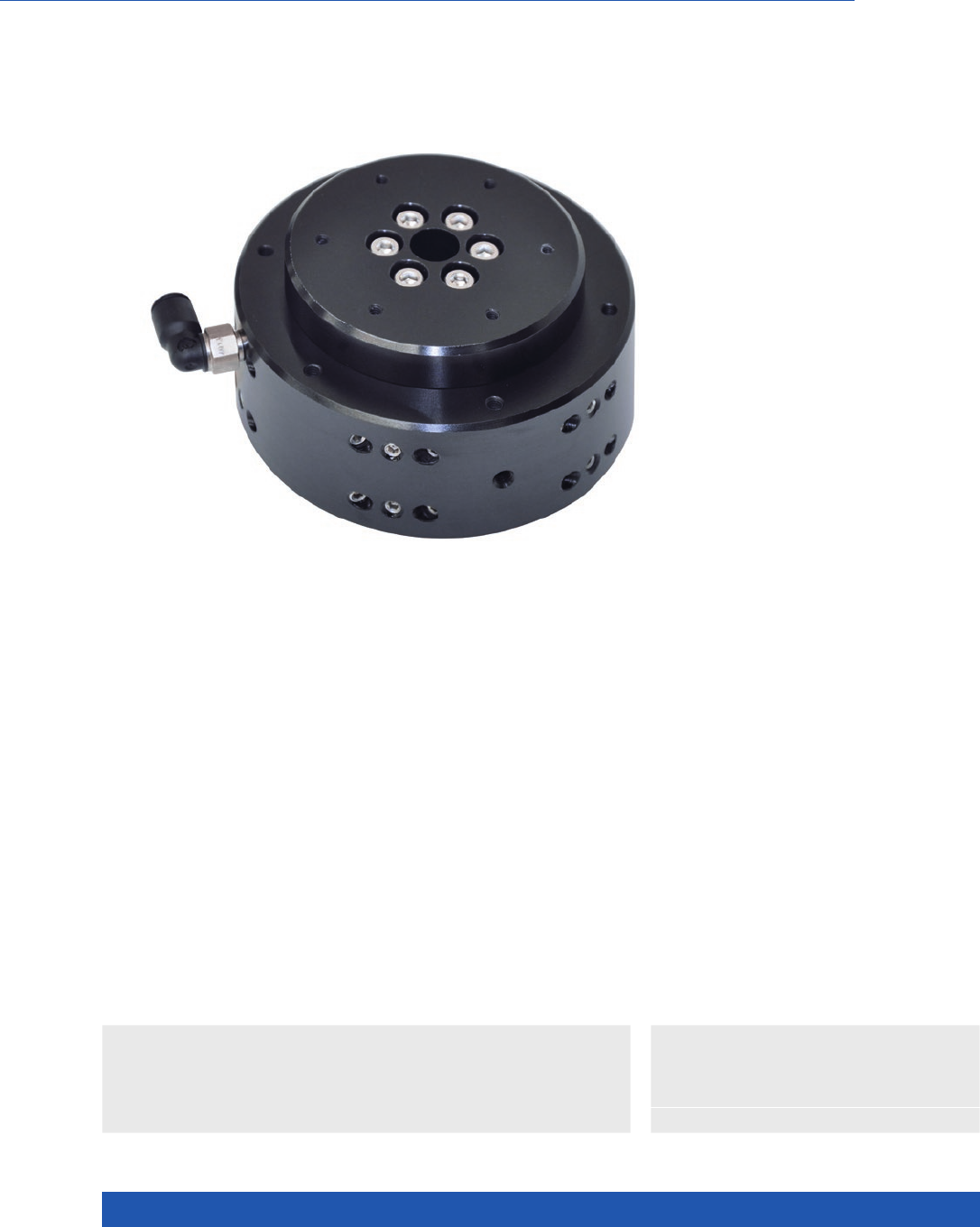
WWW.PI.WS
274
Frictionless, Nonmotorized
A-60x PIglide RT Rotary Air Bearing Module
>> PIglide Air Bearing Technology
Technology Glossary ...................... page 290
Applications
n Sample Inspection
n Scanning
n Metrology / Testing
n Optical Alignment
n Motion platform diameter from 50 mm
to 300 mm
n Load capacity to 425 kg
n Eccentricity / flatness <200 nm
n Can be mounted vertically or horizontally
n Cleanroom compatible
Accessories and options
n Encoder for precise acquisition of stage
angle during manual operation
n Mounting base for horizontal mounting
onto optical tables and flat surfaces
n PIglide filter and air preparation kits
n Customized mounting flanges and
square housings
Product Overview
The PIglide RT series of nonmotorized passive rotary air bearings are designed
for accuracy, precision, high stiffness, and ease of use. They can be used in any
orientation and are easy to integrate with motors and encoders for complete
positioning solutions.
The bearings of the RT series offer superior eccentricity, flatness, and wobble
performance. Because they are completely friction-free, they exhibit no break-
away torque and no frictional resistance during operation. They are ideal for
use in cleanrooms, require no maintenance or lubrication, and have unlimited
lifetime.

MOTION | POSITIONING
275
(1 Capacities listed assume supply pressure of 80 psi. Please contact PI if other pressures are required.
(2) Precision specifications are dependent on quality of mounting base, payload, orientation, and external forces on the bearing.
For application-specific parameters, please contact PI. Values shown are static (no rotational velocity during measurement).
(3) Velocity may be limited by the encoder option or payload imbalance. Please contact PI for further details.
(4) Alternate stage surface materials, such as stainless steel, are available. Please contact PI for a quote.
Size and
loads
Motion platform
diameter /mm
Journal length /
mm
Load capacity (1)
axial / radial /N
Permissible tip / tilt
torque (1) / N·m
Stiffness axial /
radial / N/µm
A-601.025 50 25 134 / 57 0.57 26 / 8
A-602.038 75 38 299 / 132 1. 13 57 / 22
A-603.025 100 25 536 / 115 1.70 96 / 18
A-603.050 100 50 536 / 229 4.52 96 / 35
A-604.050 150 50 1206 / 344 22.6 210 / 64
A-604.090 150 90 1206 / 605 36.7 210 / 113
A-605.065 200 65 2144 / 577 39.6 385 / 110
A-605.100 200 100 2144 / 917 67.8 385 / 175
A-607.075 300 75 4244 / 1203 141.3 788 / 204
A-607.175 300 175 4244 / 2789 282.5 788 / 475
Optional
encoders
Sensor signal Sensor
resolution /
µrad
Max.
velocity /
rpm
Reference point switch
A-601.xxxH A/B quadrature, differential,
RS-422, 4 MHz
192 2500 1 / revolution, one count over one step of
the encoder, synchronized to output signal
A-602.xxxH A/B quadrature, differential,
RS-422, max. 4 MHz
133 2000 1 / revolution, one count over one step of
the encoder, synchronized to output signal
A-603.xxxH A/B quadrature, differential,
RS-422, max. 4 MHz
100 1500 1 / revolution, one count over one step of
the encoder, synchronized to output signal
A-604.xxxH A/B quadrature, differential,
RS-422, max. 4 MHz
66.4 1000 1 / revolution, one count over one step of
the encoder, synchronized to output signal
A-605.xxxH A/B quadrature, differential,
RS-422, max. 4 MHz
50 800 1 / revolution, one count over one step of
the encoder, synchronized to output signal
A-607.xxxH A/B quadrature, differential,
RS-422, max. 4 MHz
33.5 500 1 / revolution, one count over one step of
the encoder, synchronized to output signal
Performance
specifications
Eccentricity (2) /
nm
Flatness (2) /
nm
Wobble (2) /
µrad
Max.
velocity (3) /
rpm
Moment
of inertia /
kg·mm²
Rotating
mass / kg
Overall
mass / kg
A-601.025 300 100 53000 35 0.15 0.4
A-602.038 250 75 4 3000 231 0.4 1.2
A-603.025 175 75 2.5 3000 705 0.7 1.5
A-603.050 175 75 2.5 3000 750 0.8 2.5
A-604.050 100 50 2 3000 4715 2.1 5.4
A-604.090 100 50 2 3000 5050 2.6 8.2
A-605.065 100 50 1.5 2000 17900 4.6 11. 6
A-605.100 10 0 50 1.5 2000 18800 5.3 16.3
A-607.075 75 40 1 1000 181900 19.4 38.1
A-607.175 75 40 1 1000 206700 26.0 59.0
A-60x
Miscellaneous
Operating pressure 75 to 85 psi (515 to 585 kPa)
Air consumption <2.0 SCFM (57 SLPM)
Air quality Clean (filtered to 1.0 µm or better) – ISO 8573-1 Class 1
Oil free – ISO 8573-1 Class 1
Dry (–15 °C dew point) – ISO 8573-1 Class 3
Materials (4) Hardcoat aluminum, stainless steel fasteners
Components &
Accessories
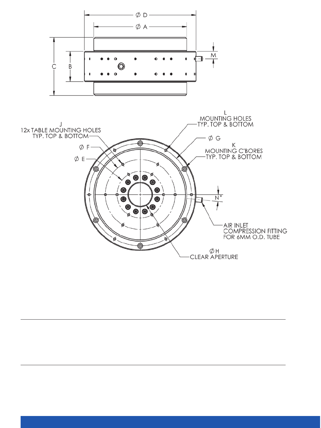
WWW.PI.WS
276
Model A B C D E F G H J K L M N
A-601.025
A-602.038
A-603.025
A-603.050
A-604.050
A-604.090
A-605.065
A- 60 5.100
A-607.075
A- 607.175
50
75
100
100
150
150
200
200
300
300
25
38
25
50
50
90
65
100
75
175
50
65
55
80
95
135
125
160
150
250
70
100
125
125
185
185
240
240
355
355
25
30
50
50
75
75
100
100
150
150
40
50
75
75
125
125
150
150
250
250
60
87.5
112.5
112.5
170
170
220
220
330
330
8
12.5
25
25
40
40
60
60
75
75
M3x0.5, 6 DEEP
M3x0.5, 6 DEEP
M4x0.7, 8 DEEP
M4x0.7, 8 DEEP
M5x0.8, 10 DEEP
M5x0.8, 10 DEEP
M6x1.0, 12 DEEP
M6x1.0, 12 DEEP
M6x1.0, 12 DEEP
M6x1.0, 12 DEEP
3x M3 SHCS, 30 LG. MIN
3x M4 SHCS, 40 LG. MIN
3x MS SHCS, 30 LG. MIN
3x MS SHCS, 50 LG. MIN
4x M6 SHCS, 50 LG. MIN
4x M6 SHCS, 90 LG. MIN
6x M6 SHCS, 70 LG. MIN
6x M6 SHCS, 100 LG. MIN
6x M8 SHCS, 80 LG. MIN
6x M8 SHCS, 150 LG. MIN
3x M3x0.5, 6 DEEP
3x M4x0.7, 8 DEEP
3x M5x0.8, 10 DEEP
3x M5x0.8, 10 DEEP
4x M6x1.0, 12 DEEP
4x M6x1.0, 12 DEEP
6x M6x1.0, 12 DEEP
6x M6x1.0, 12 DEEP
6x M8x1.25, 16 DEEP
6x M8x1.25, 16 DEEP
6
9.5
6
12.5
12.5
22.5
16
23.5
17. 3
58.5
30
30
30
30
68
68
5
5
5
5
A-60x.xxx, dimensions in mm
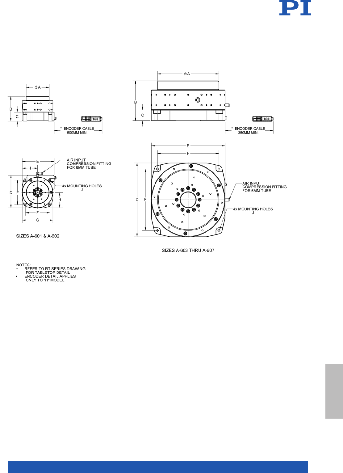
MOTION | POSITIONING
277
Model A B C D E F G H J
A-601.025 M or H
A-602.038 M or H
A-603.025 M or H
A-603.050 M or H
A-604.050 M or H
A-604.090 M or H
A-605.065 M or H
A-605.100 M or H
A-607.075 M or H
A-607 175 M or H
50
75
100
100
150
150
200
200
300
300
65
80
65
90
100
140
130
165
155
255
26.5
28.5
25
25
27.5
27.5
35
35
42.5
42.5
82
106
135
135
185
185
240
240
355
355
74
104
125
125
185
185
240
240
355
355
55
80
100
100
150
150
200
200
300
300
70
100
-
-
-
-
-
-
-
-
35
50
-
-
-
-
-
-
-
-
M3 SHCS, 25 LG. MIN
M4 SHCS, 30 LG. MIN
M5 SHCS, 25 LG. MIN
M5 SHCS, 25 LG. MIN
M6 SHCS, 30 LG. MIN
M6 SHCS. 30 LG. MIN
M6 SHCS, 35 LG. MIN
M6 SHCS, 35 LG. MIN
M8 SHCS, 40 LG. MIN
M8 SHCS, 40 LG MIN
A-60x.xxxH and A-60x.xxxM, dimensions in mm
Components &
Accessories
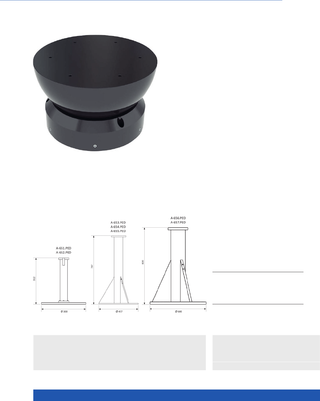
WWW.PI.WS
278
Friction-free, ideal for rotary motion on three axes
A-65x PIglide HB: Hemispherical Air Bearing
>> PIglide Air Bearing Technology
Technology Glossary ...................... page 290
Applications
n Semiconductor
n Optical Alignment
n Scientific
Instrumentation
n Cleanroom compatible
n Low inertia
n Diameter up to 300 mm
n Rotatable in three directions
n Load capacity to 635 kg
n Tip / tilt range to ±45°
n Operating pressure from 30 psi to 90 psi
(207 kPa to 621 kPa)
n Ideal for satellite control and simulation
of weightlessness
Overview
The spherical bearings, which are often used in
research on weightlessness in satellites, are also
used in systems for precision chip contacting and
optical alignment. Due to the use of spherical
bearings at both ends of the drive screw shaft, it
is possible to build extremely stiff drive screws.
This arrangement allows precision alignment of
the drive screw shaft due to the motion of one
spherical bearing relative to the other.
Accessories and options
n Air preparation kit
n Custom configurations on request
Model Mass / kg Compatible with
A-651.PED
A-652.PED
A-653.PED
A-654.PED
A-655.PED
A-656.PED
A-657.PED
3.1
4.0
16
16
17
43
44
A-651.xxx
A-652.xxx
A-653.xxx
A-654.xxx
A-655.xxx
A-656.xxx
A-657.xxx
A-65x.PED Matching pedestal for each
A-65x model, dimensions in mm
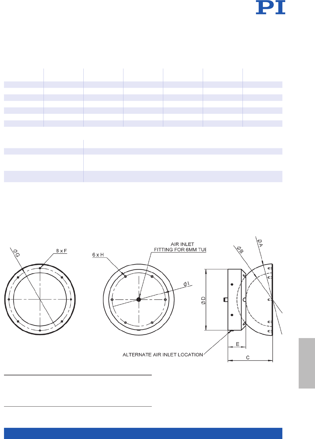
MOTION | POSITIONING
279
Model Sphere
diameter / mm
Rotation
range**/ °
Load
capacity* / kg
Base mass / g Sphere
mass / g
Moment of
inertia*** / g·m2
A-651 50 ±45 15 11 5 70 0.02
A-652 75 ±45 35 235 216 0.14
A-653 100 ±45 65 550 475 0.58
A-654 150 ±45 160 1350 1475 4.21
A-655 200 ±45 265 2500 3350 1 7. 2
A-656 250 ±45 405 4000 5525 46.3
A-657 300 ±45 635 6500 8100 103
Operating pressureperating pressure 80 psi (550 kPa) nominal, 90 psi (621 kPa) maximum
Air consumption <1.0 SCFM (28 SLPM)
Air quality Clean (filtered to 1.0 µm or better) – ISO 8573-1 Class 1
Oil free – ISO 8573-1 Class-1
Dry (–15 °C dew point) – ISO 8573-1 Class 3
Materials Hardcoat aluminum, stainless steel fasteners
alternative materials on request
* The specified load capacities assume an operating pressure of 80 psi (550 kPa).
For an alternative operating pressure, contact PI for determining other load capacities.
** Other travel ranges on request.
*** Around the center of the sphere.
Model A B C D E F G H I
A-651
A-652
A-653
A-654
A-655
A-656
A-657
50
75
100
150
200
250
300
30
50
70
110
150
200
250
42
55
70
95
125
150
175
55
70
100
140
170
210
250
23
27
30
40
50
55
65
M3
M3
M4
M5
M5
M6
M6
38
60
85
125
175
225
275
M3
M3
M4
M5
M5
M6
M6
45
60
85
125
150
190
230
A-65x.045, dimensions in mm
Components &
Accessories
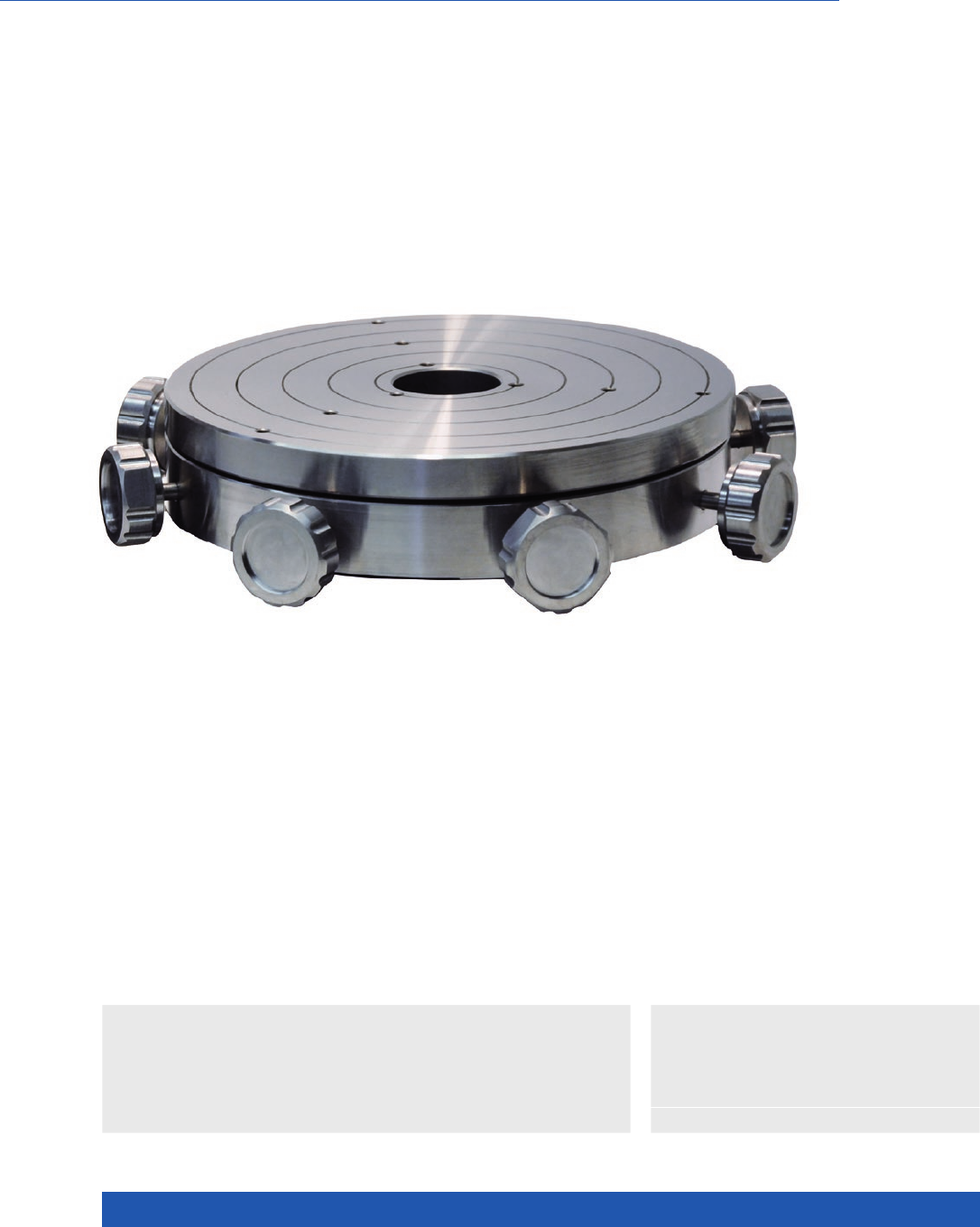
WWW.PI.WS
280
Compatible with A-60x and A-62x
A-60x.MTT PIglide Manual X-Y-Tilt Platform
>> PIglide Air Bearing Technology
Technology Glossary ...................... page 290
Applications
n Sample Inspection
n Metrology / Testing
n Optical Alignment
n Motion platform diameter 75 to 300 mm
n Manual operation
n 4 degrees of freedom: X, Y, θX, θY
n Clear aperture
n Can be mounted directly onto an A-60x and A-62x
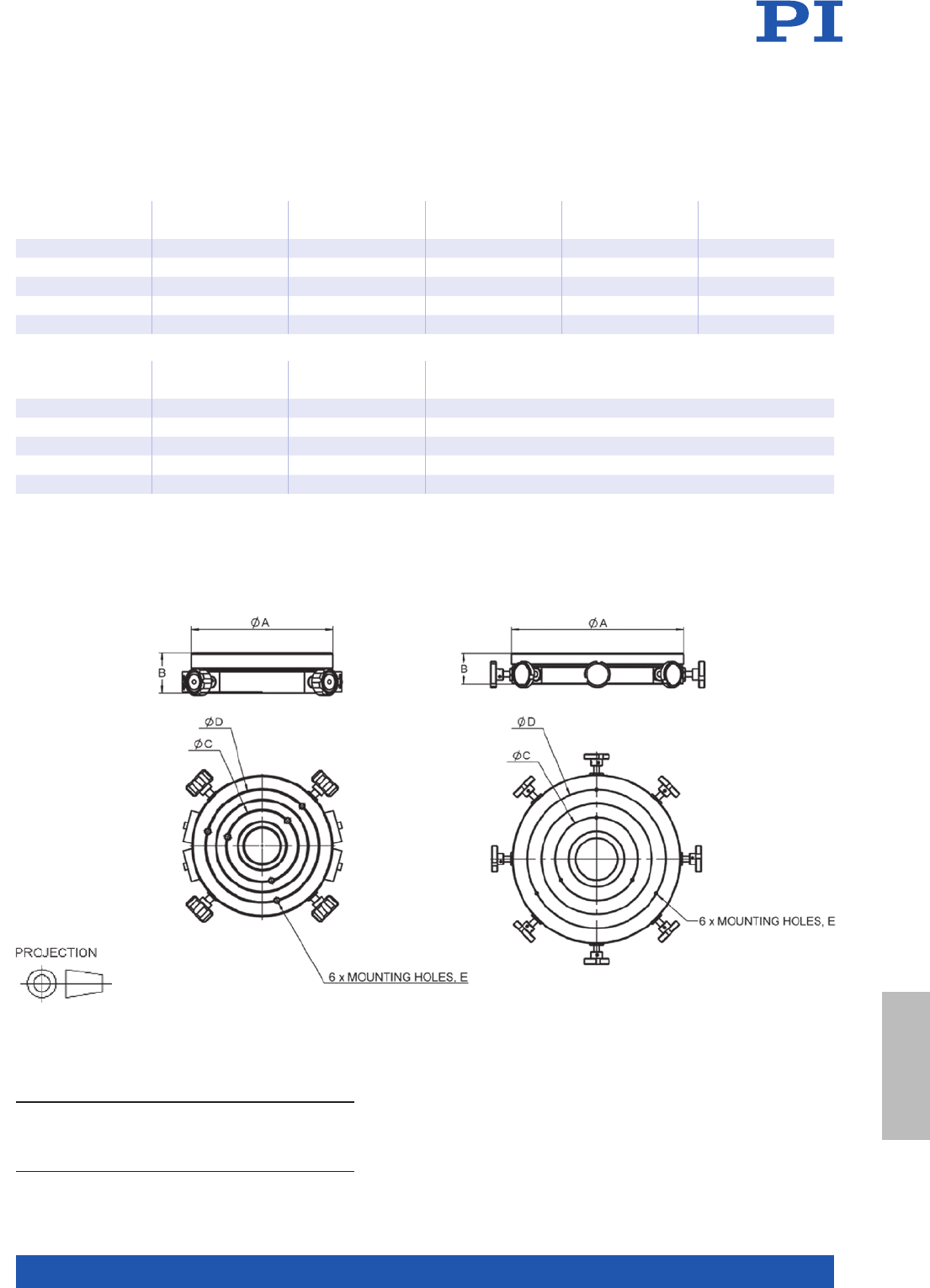
MOTION | POSITIONING
281
Model Motion platform
diameter /mm
Travel range X,Y Travel range θX, θYOverall mass /kg Moment of
inertia /kg·mm²
A-602.MTT 75 ±1.5 mm ±1.25° 0.8 620
A-603.MTT 100 ±1.5 mm ±1.25° 1. 5 2090
A-604.MTT 150 ±3 mm ±1.25° 4 12900
A-605.MTT 200 ±3 mm ±1.25° 8.6 52100
A-607.MTT 300 ±3 mm ±1.25° 25 319000
Model Motion platform
diameter /mm
Compatible
with A-60x
Compatible
with A-62x
A-602.MTT 75 A-602.xxx
A-603.MTT 100 A-603.xxx A-623.xxx
A-604.MTT 150 A-604.xxx A-624.xxx
A-605.MTT 200 A-605.xxx
A-607.MTT 300 A-607.xxx A-627.xxx
Model A B C D E
A-602.MTT
A-603.MTT
A-604.MTT
A-605.MTT
A- 607.MT T
75
100
150
200
300
25
30
35
45
55
30
50
75
100
150
50
75
125
150
250
M3x0.5, 6 DEEP
M4x0.7, 8 DEEP
M5x0.8, 10 DEEP
M6x1.0, 12 DEEP
M6x1.0, 12 DEEP
A-60x.MTT, dimensions in mm
A-604 through A-607A-602 / A-603
Components &
Accessories
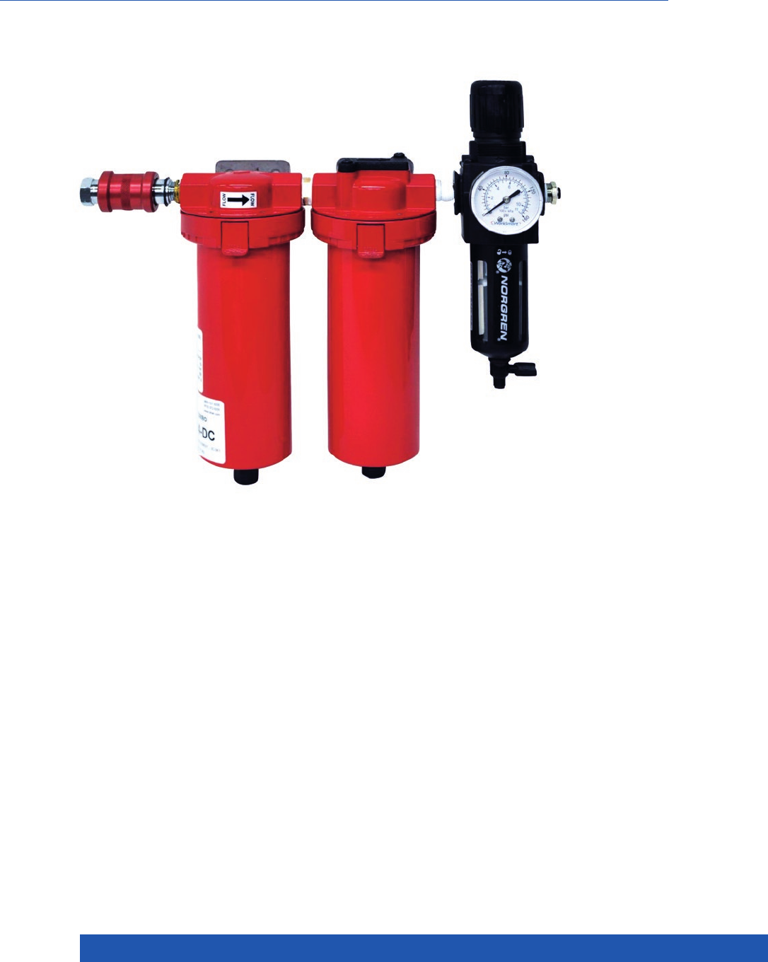
WWW.PI.WS
282
n Cleans and filters the compressed
air supply
n Controls the supply pressure
n Optional pressure switch
n Recommended for use with all
PIglide air bearing products
n Customized adaptations possible
Multi-stage Filtration System with Pressure Regulation
A-80x PIglide Filter and Air Preparation Kits
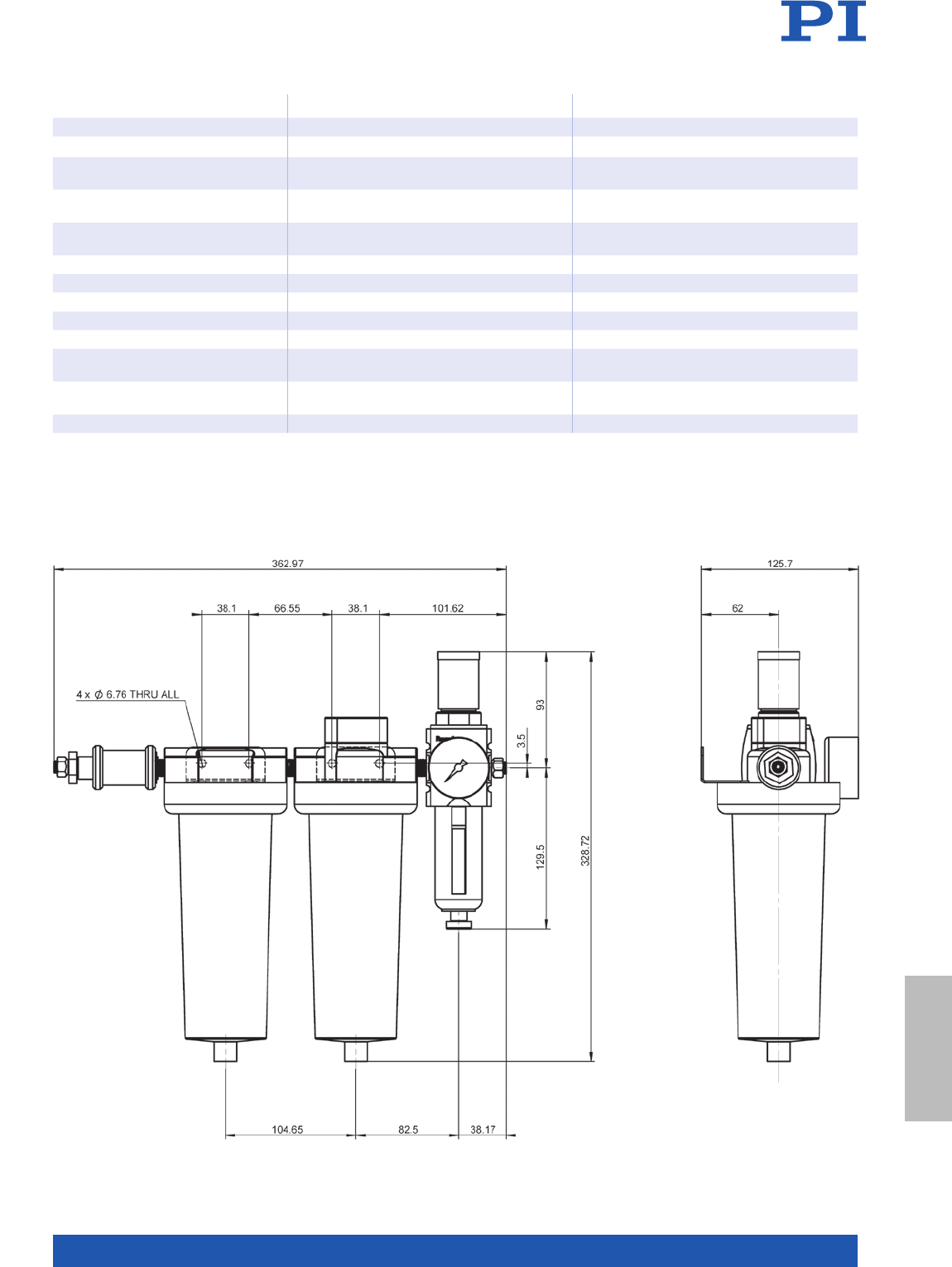
MOTION | POSITIONING
283
A-801 A-802
Description 4-stage air preparation kit 2-stage air preparation kit
Air supply
Maximum flow 60 SCFM
(1680 SLPM)
10 SCFM
(300 SLPM)
Compressed air supply quality
(ISO 8573-1)
As desired Class 3 or better
Max input pressure 150 psi
(1035 kPa)
150 psi
(1035 kPa)
Miscellaneous
Primary construction Aluminum Polycarbonate
Mass 4.2 kg 0.7 kg
Options
Option 1 pressure switch 1 = none 2 = N/O contact, adjustable threshold value
Option 2 Air input connection 0 = quick connection, 6 mm and 8 mm
outer diameter in the scope of delivery
3 = quick connection 1/4” and 3/8” outer
diameter in the scope of delivery
Option 3 Air output connection 0 = quick connection, 6 mm and 8 mm
outer diameter in the scope of delivery
3 = quick connection 1/4” and 3/8” outer
diameter in the scope of delivery
All modules require a compressed air supply with dry air according to ISO 8573-1 Class 3 or better (dew point no greater than 0°C).
A-801.100, dimensions in mm
Components &
Accessories
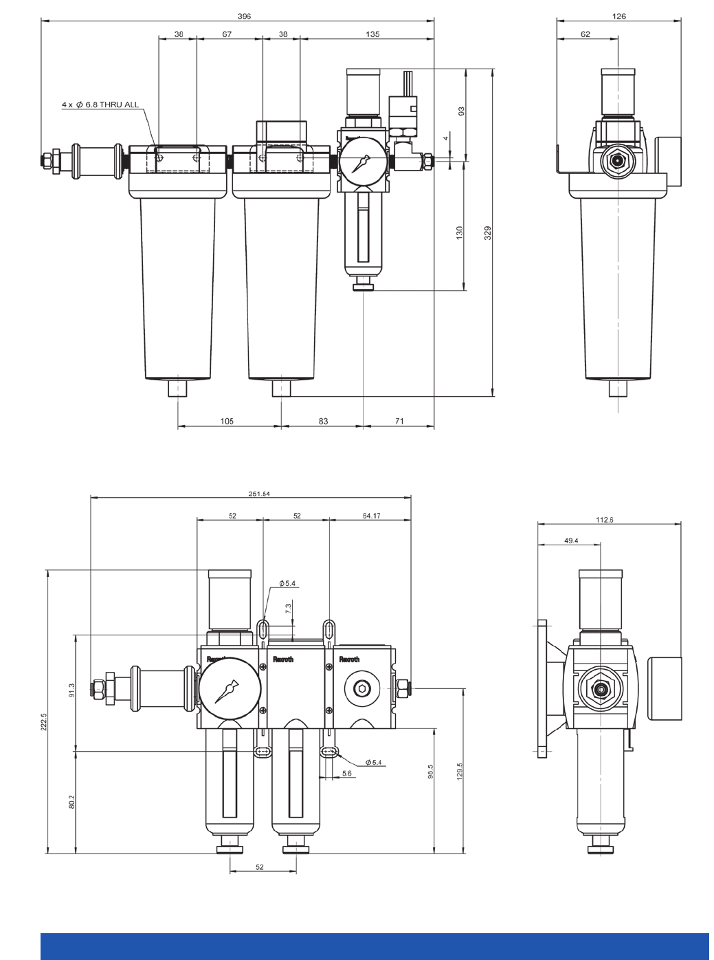
WWW.PI.WS
284
A-801.200, dimensions in mm
A-802.100, dimensions in mm
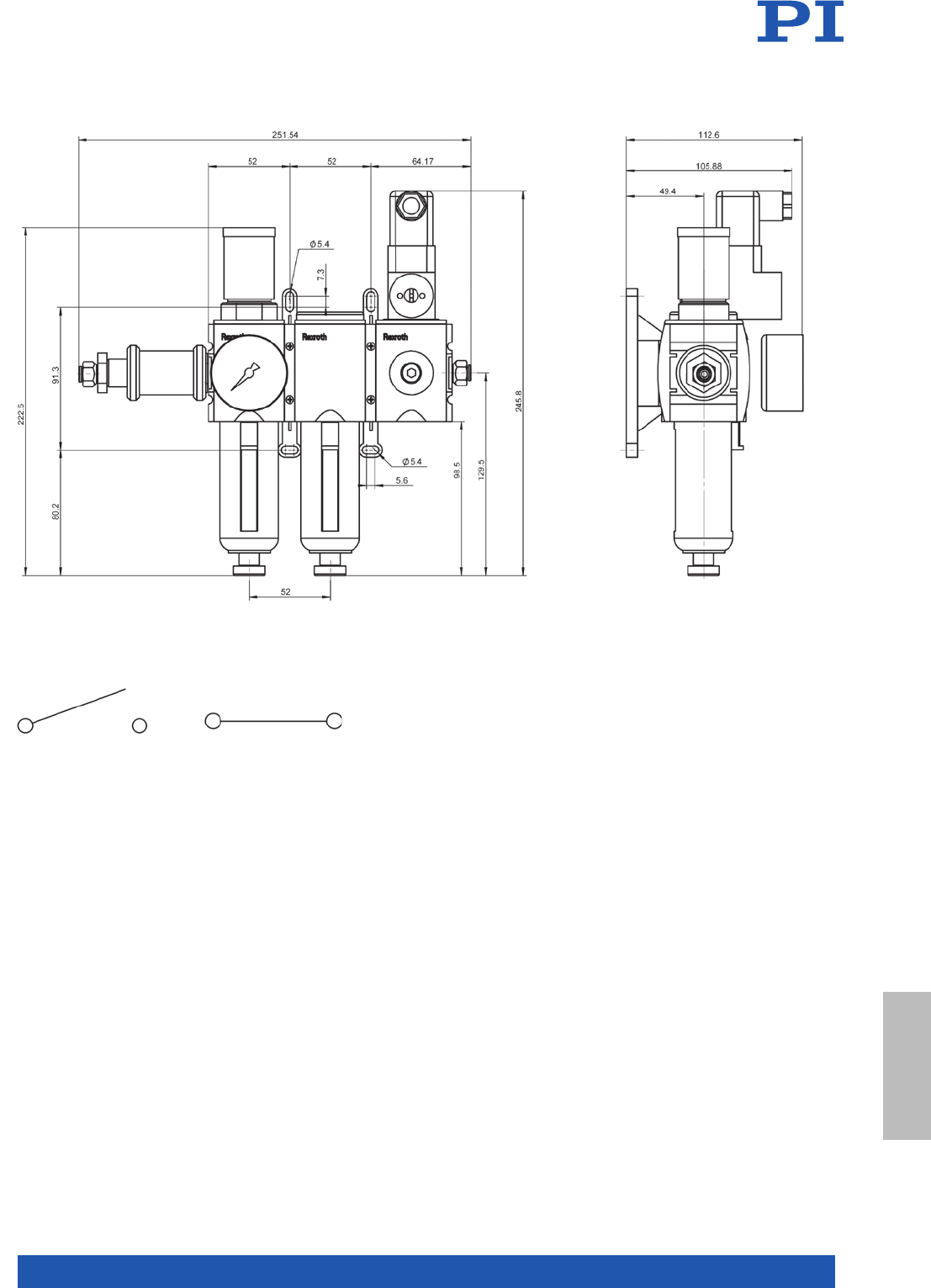
MOTION | POSITIONING
285
A-802.200, dimensions in mm
Air pressure below the threshold value, pressure switch opened (left).
Air pressure above the threshold value, pressure switch closed (right).
Components &
Accessories
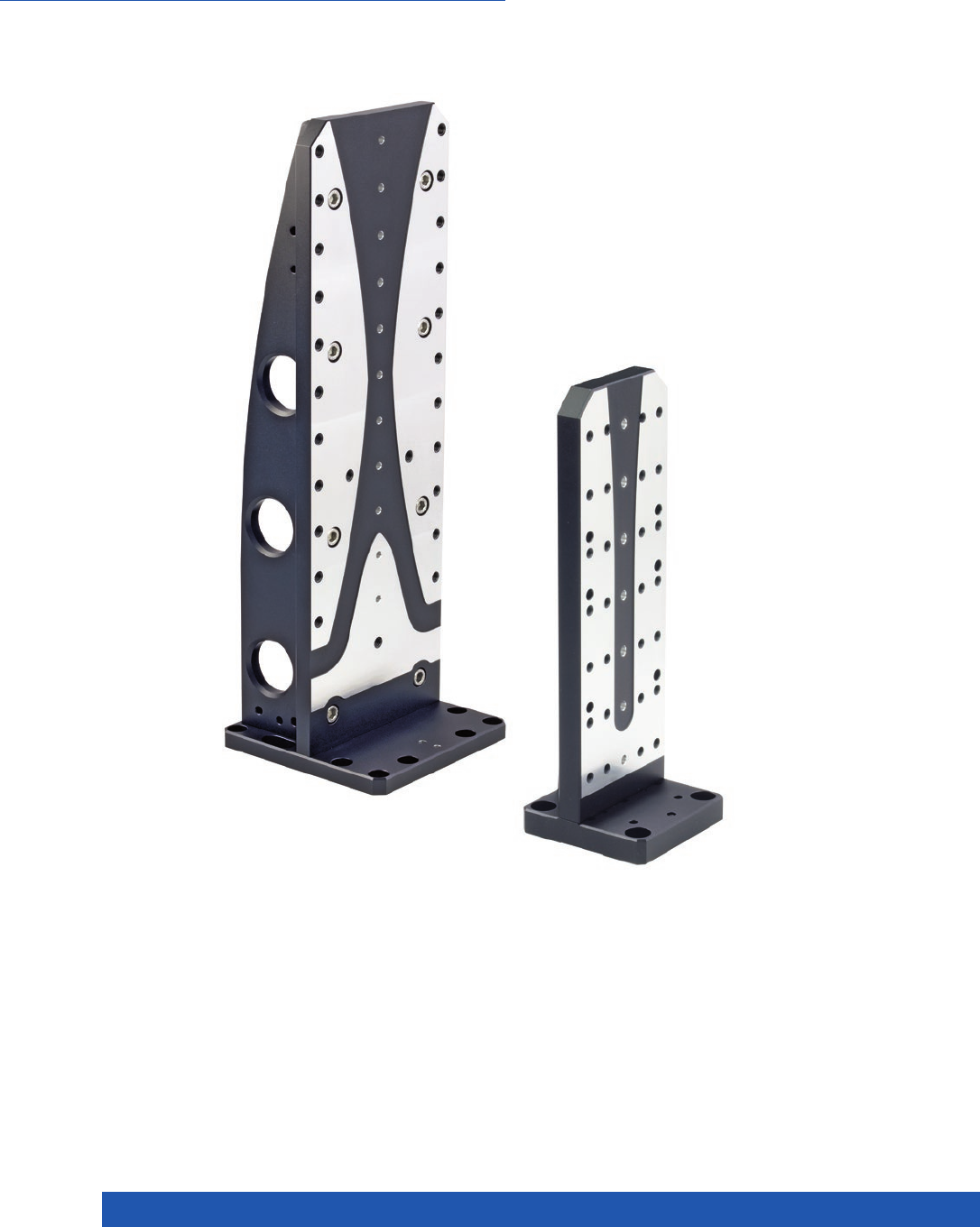
WWW.PI.WS
286
For Vertical Mounting of Linear and Rotation Stages
L-500 Adapter Bracket

MOTION | POSITIONING
287
L-500.AV1
(Angle to axis)
L-500.AV1
(Axis to angle)
L-500.AV3
(Angle to axis)
L-500.AV3
(Axis to angle)
Linear stages
HPS-170 X X* X –
L-406 – – X X
L-408 –––X
L-412 XXX–
L-417 X – – –
V-412 X X X
V-417 X – – –
L-509 – – X X
L- 511 X X* X –
LS-180 X – X –
UPL-120 – – – X
Rotation stages
DT-80 – – – X
L- 6 11 – X X –
UPR-100 – – – –
UPR-120 – X X –
UPR-120 AIR – X X –
Goniometers
WT-85 – – X X
WT-90 – – X –
WT-100 –––X
WT-120 – – X –
Z stage
L-306 – – X –
L-310 – – X –
XY stage
L-731 X – X –
V-731 X – X –
L-741 X – X –
V-741 X – X –
* to 155 mm stroke
Ask about custom designs!
Components &
Accessories
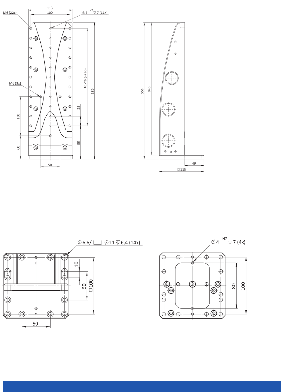
WWW.PI.WS
288
Top view of the L-500.AV1 adapter bracket,
dimensions in mm
Bottom view of the L-500.AV1 adapter bracket,
dimensions in mm
L-500.AV1, dimensions in mm
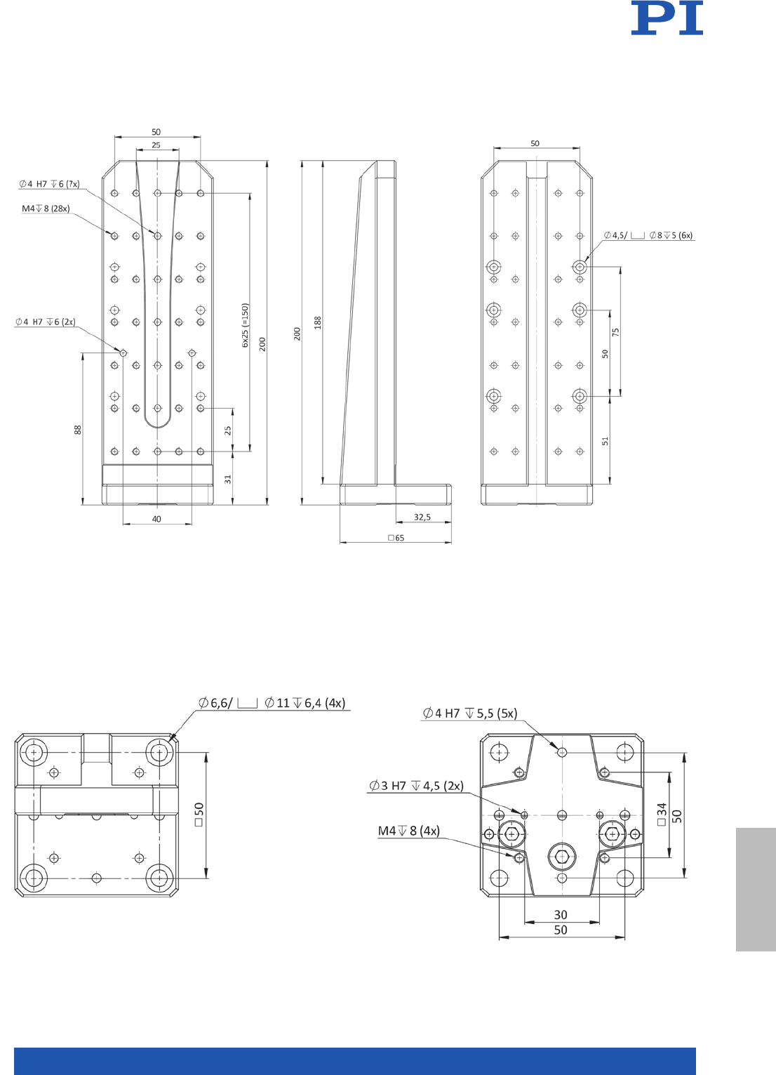
MOTION | POSITIONING
289
Top view of the L-500.AV3 adapter bracket,
dimensions in mm
Bottom view of the L-500.AV3 adapter bracket,
dimensions in mm
L-500.AV3, dimensions in mm
Components &
Accessories

WWW.PI.WS
290
Terms and Technology Glossary
A
Absolute encoder
Absolute encoders are used for detecting the position and pro-
vide information on the absolute position of a motion platform.
For example, this can be realized optically by using an additional
Pseudo Random Code (PRC) scale.
ActiveDrive motor
The ActiveDrive Motor also integrates a servo amplifier into
the motor housing, which is driven in PWM mode (Pulse Width
Modulation). The operating voltage, which is mostly 24 V for
ActiveDrive motors, is supplied by a separate power supply.
Advantage: Lower costs, more compact design and higher
reliability compared to an externally cabled amplifier; a higher
degree of efficiency due to elimination of power loss between
the amplifier and motor; avoidance of radiation interference
because the amplifier and motor are built into the same shield-
ed housing.
Air bearing
An air film of a few micrometers is used as bearing. Therefore,
air bearings are free of friction and, compared to mechanical
bearings, allow a considerably higher guiding accuracy. See
“PIglide Air Bearing Technology”.
Average current
Current that is available reliably over a longer period. Given as
measured value. For multi-axis controllers, it is specified per
channel.
B
Ball screw
In the case of ball screws, only rolling friction occurs, which
allows higher speeds, drive performance, and longer lifetime
than leadscrews. They are however, not self-locking. The back-
lash can be minimized adjusting the ball diameter and the thread
profile.
Brushless DC Motor (BLDC)
Compared to conventional DC motors, BLDC motors manage
without wear-prone brushes meaning that a considerably lon-
ger lifetime is possible. Commutation is fully electronic and is
generated completely by a rotating magnetic field in the stator
that drags the rotor; the motor is based more on the concept
of a synchronous machine. If sine commutation and a servo
amplifier are used for position control instead of block commu-
tation, the term synchronous servo motor (SSVM) is often
encountered. Compared to DC motors, it is possible to realize a
smaller and lighter design and provide the same performance,
which results in a high ratio between the torque and the motor
size. At the same time, the drivetrain can be shorter for the same
travel range because the drive shaft is located inside the motor.
C
Capacitive sensor
Capacitive sensors allow contactless measuring, do not intro-
duce much energy into the drive system and have a flat design.
Their direct position measurement eliminates drift effects for
travel ranges of up to 1.5 mm. The overall system, which con-
sists of the stage, sensor technology, and electronics, gains on
performance and precision. Due to noncontact measuring in
the 10 µm up to approx. 2 mm range, it is possible to mount the
capacitive sensor in the stage at the point where the motion
actually takes place. The design consists of two conductive
surfaces: A high-frequency alternating current generates a
homogenous electric field between the two surfaces. Customers
from the semiconductor industry also appreciate the small and
versatile design as well as the lack of thermal build-up in the
system. See “Sensor linearization”.
Closed-loop operation
Additional position feedback makes it possible to operate motors
in a closed servo loop. Feedback of the corresponding encoder
signals is necessary for this purpose. Basically, this concept
makes it possible to control the rotational speed, the position,
and the torque, which allows realization of a high position reso-
lution, a uniform feed rate, and a large dynamic range for velo-
city and acceleration at a constant torque.
Creep
An unwanted change in the displacement over time.
Crossed roller guide
Crossed roller guides are comparatively stiff and manage with
low preload. This results in reduced friction with high load capa-
city, high guiding accuracy, and smooth running. An additional
forced cage control helps to prevent the roller bearing from creep-
ing. Nevertheless, this shortens the possible travel range over
the same axis length.

MOTION | POSITIONING
291
Crosstalk
Deviation from the ideal motion in axes perpendicular to the
direction of motion.
Angular errors are xrx = roll, xry = pitch, xrz = yaw. Linear errors
are lateral runout such as xty = straightness, xtz = flatness. See
“Linearity error”.
Current consumption
Current consumption of the system on supply end. It is specified
for controller without load. Alternatively, power consumption.
Current limitation
Short-circuit protection.
D
DC motor
A DC motor exploits the force effect of the electrical current via
a pivoted conductor loop in a magnetic field. In conjunction with
servo controllers (see “servo motor”) , these types of motors
allow high torques at lower motor speeds, good dynamics over
a large speed range, faster response, lower heat generation as
well as smooth and vibration-free operation. The disadvantage
is the wear-prone brushes used for commutation that does
result in a comparatively shorter lifetime. However, due to their
low holding force, DC motors (without gearhead) are generally
not suited for vertically oriented axes.
Design resolution
The theoretical minimum movement that can be made. Design
resolution must not be confused with minimum incremental
motion. In indirect position measurement methods, values for
spindle pitch, gear ratio, motor or sensor / encoder resolution,
for example, are included in the calculation of the resolution;
normally it is considerably below the minimum incremental
motion of a mechanical system. Indirect measurement methods,
the resolution of the sensor is specified.
Direct metrology
Position measuring is performed with the highest accuracy
directly at the motion platform so that nonlinearity, mechani-
cal play or elastic deformation have no influence on position
measuring. This is achieved by noncontact optical linear enco-
ders. Precision positioning systems use different encoder types
as position sensor: Incremental encoders with different accuracy
levels, absolute-measuring encoders that additionally make ref-
erencing unnecessary when a machine is switched on again, and
for travel ranges under 2 mm, capacitive sensors.
Drift
See “Creep”.
Drive type
Defines the types of drive supported by the controller / driver,
such as voice coils, linear motors, DC/BLDC motors, stepper
motors and others.
E
Encoder
An encoder is used for determining the position. Basically, a
difference is made between linear and rotary encoders, which,
depending on the configuration, operate either incrementally
or absolutely.
Encoder input
Maximum bandwidth (-3 dB) of the input signals for the encoder
input.
Extensive software package
To make systems more user friendly, software plays an impor-
tant role in positioning systems. Customers expect a plug-and-
play solution even if several positioning systems are combined
or different drive systems need to interact, and that is why PI
(Physik Instrumente) provides PIMikroMove® host software. You
only need to enter your parameters into the application to avoid
programming altogether. Also supports a number of text-based
languages, has its own LabVIEW, Python and Matlab drivers,
and the software is compatible with Windows, Linux, and OSX.
However, not all software tools may be available for all control-
ler versions.
F
Flatness
See “Crosstalk”.
Flexures
The motion of a flexure is based on elastic deformation of a
solid. This avoids any static, rolling or sliding friction. Flexure
elements have high stiffness and load capacity and are very
insensitive to shocks and vibrations. They do not wear, require
no maintenance, are completely vacuum compatible, function
in a wide temperature range, and do not require any lubricants.
Terms and Technology
Glossary

WWW.PI.WS
292
Terms and Technology Glossary
G
Gearhead
Gearheads allow adjustment of the speed and the torque. How-
ever, the transmission ratio, which is the proportion between the
speed and the gear input, is decisive and the speed is defined
at the gear output. In the case of transmission reduction, this
ratio is greater than one, which results in a lower speed with a
higher torque. The opposite applies in the case of higher speeds.
Typical types of gears include for example, worm gears, spur
gears, planetary gears, bevel gears, and belt gears.
I
ID chip
An ID chip is located in the connector of many stages. When
the stage is calibrated at the factory with a digital controller, the
calibration data is saved together with specific product infor-
mation on the ID chip. When switched on, digital electronics
read the data from the ID chip of the connected stage. Stages,
whose ID chip contains the calibration data, can therefore be
connected to any suitable digital electronics without renewed
calibration.
Incremental encoder
When incremental encoders are in motion, they generate impuls-
es that are counted by the controller. However, in contrast to
absolute encoders, it is a question of determining a relative
position. To determine an absolute position, a limit switch or
reference point switch signal must also be referenced.
Input level
Permissible input level for digital interfaces.
Integrated feedback sensor
Absolute measuring capacitive, piezo resistive (PRS) or strain
gauge (SGS) and optical (absolute and relative) sensors are used
to provide position information to the controller.
L
Lateral force, max.
Maximum lateral force perpendicular to the operating direction.
For XY stages the push/pull force capacity of the other module
(in its operating direction) limits the lateral force that can be
tolerated.
Leadscrew
Leadscrews can achieve very high resolutions with smooth run-
ning and are often preloaded by springs to minimize backlash.
This results in sliding friction and therefore a self-locking effect.
However, this reduces the speed, performance, and the lifetime.
Limit switch
Function: Optical, magnetic.
Linear ball guiding
Linear ball guides require exact tolerances between the guide
and bearing in order to keep the play and friction as low as
possible. This limits the load capacity. Due to the simple design,
they are only suitable for inexpensive applications with compa-
ratively low requirements.
Linear encoder
Linear encoders measure the position directly at the motion plat-
form. As a rule, this means that a higher accuracy is achieved
compared to rotary encoders, because nonlinearity, mechanical
play, and elastic deformation have no influence.
Linear motor
A linear motor is an electromagnetic direct drive that generates
straight linear motion. The range of a linear motor is practical-
ly unlimited. A linear measuring system is always required for
motion and positioning; open loop operation of a linear motor
is not possible. The linear motor does not require mechanical
coupling elements to convert the rotation of the motor into lin-
ear motion as is the case with servo motors. Typically, 3-phase
motors are used.
Typical applications are found in the electronics and semicon-
ductor industry, medicine and biotechnology, in tool machines
with a strong focus on laser cutting but also in other fields where
precision, dynamics, and productivity are important.
Linearity error
Deviation in motion direction, of measured position from com-
manded position (positioning accuracy). Measured with an
external, traceable device. The value is given as a percentage
of the entire measuring range.
Measurement of the linearity error: The target and measured
actual values of the positions are plotted against each other,
a line is drawn through the first and last data point, and the
maximum absolute deviation is determined. A linearity error of
0.1 % corresponds to an area of ±0.1 % around the ideal line.
Example: A linearity error of 0.1 % over a measuring range of
100 µm produces a possible maximum error of 0.1 µm.
Load capacity
Maximum vertical load, when the stage is mounted horizontally.

MOTION | POSITIONING
293
M
Magnetic bearing
Magnetic levitation allows excellent linear and rotational guiding
accuracy on a plane. The passive runner hovers of a magnetic
field and is then actively guided by it. Flatness errors are measur-
ed and compensated by very accurate noncontact sensors. Con-
trary to air bearings, which are also very accurate, magnetic
bearings can also be used in vacuum.
Measurement range extension factor
For capacitive sensors, used by PI.
N
Noise
For capacitive sensors. In extended measurement ranges, noise
is considerably higher than in the nominal measurement range.
Nonlinearity
See “Linearity error”.
O
Open-loop operation
The actuator is used without a position sensor. Displacement
roughly corresponds to the drive voltage. Creep, nonlinearity
and hysteresis remain uncompensated. Open-loop operation is
ideal for applications where fast response and very high resolu-
tion with maximum bandwidth are essential. Here, commanding
and reading the target position in absolute values is either not
important or carried out by external position sensors. Open-loop
operation is not possible for electro-magnetic direct drives, such
as linear motors and voice-coil drives.
Operating temperature range
In any case, the device can be operated safely in the maximum
permissible temperature range. To avoid internal overheating
however, full load is no longer available above a certain tem-
perature (maximum operating temperature under full load). Never-
theless, recalibration or zero-point-adjustment may be required
if the system is operated at different temperatures. Performance
specifications are valid for room temperature range. Please refer
to individual datasheets and contact PI for more details.
Operating voltage
Allowed control input voltage range (also input frequency) for
the supply of the device.
Overtemperature protection
Switch-off temperature for voltage output. No automatic restart.
P
Patents
PI owns a large variety of patents on piezo and motor techno-
logy.
Parallel kinematics, hexapods
Hexapods are parallel-kinematic systems with six drives that are
connected directly to a single platform. This makes it possible
for users to position objects automatically in all degrees of free-
dom, X, Y, Z, and rotatory and, depending on the drive, with an
accuracy in the micrometer range or lower. The parallelkinematic
system is very stiff, with only a low passive weight to move and,
with the corresponding design, can carry loads of up to several
tons. Users are able to arbitrarily choose the reference coordi-
nate system and, today, workers are now working together with
hexapods on the production line. The user integrates the system
into the automation environment via EtherCAT.
Parallel metrology
Each sensor measures the position of the same moving plat-
form in the respective degree of freedom. This keeps the off-axis
runout, or crosstalk, of all actuators inside the servo-control loop
and allows it to be corrected automatically.
Peak current
Only available for very short times, typically under a few mil-
liseconds. It is used to estimate the possible dynamics with a
certain capacitive load. Note: In this case, the controller / driver
does not necessarily work linearly.
Piezoresistive sensor (PRS)
Strain gauge sensors that consist of a semiconductor foil. See
“Strain gauge sensors”.
PIglide Air Bearing Technology
The PIglide air bearing technology allows friction-free position-
ing with a high guiding accuracy of up to 5 µrad over 100 mm.
The technology improves the position resolution and it is possib-
le to realize constant-velocity scanning. The repeatability is only
a few encoder impulses. A similar precision in the nanometer
range is also possible with flexure-guided piezo nanoposition-
ers, however, only over considerably shorter travel ranges. The
developers at PI (Physik Instrumente) adapt high-precision, air
bearing positioning stages and motion control systems accord-
ing to customer requirements.
Terms and Technology
Glossary

WWW.PI.WS
294
Terms and Technology Glossary
PIMag® Magnetic Linear Motors
Magnetic direct drives from PI (Physik Instrumente) provide a
direct and stiff connection between the load to be moved and
the drive. The industry demand is particularly high when objects
need to be positioned with high dynamics and precision. Thanks
to the smooth-running precision linear guides with crossed roll-
er bearings, these types of linear motor stages are particularly
suitable for applications that require constant-velocity scanning.
The drives operate without contact and therefore very reliable.
Users can integrate the magnetic direct drives into existing ma-
chines and systems quickly and easily via standardized fieldbus
systems. See “Linear motor”, “Torque motor”
PIMag® Voice Coil
Thanks to their low weight and friction-free drive principle, voice
coil drives are small and particularly suitable for applications
that require high dynamics and high velocities over limited
travel ranges – for example, in medical technology. Voice coil
drives have a greater advantage for the customer when com-
pared to traditional drive screw-based solutions, particularly
with respect to wear and dynamics. High scan frequencies and
precision positioning are possible with these drives, because
they are free of hysteresis effects. See “Voice Coil Drive”.
Pitch
See “Crosstalk”.
Power consumption
Maximum power consumption under full load.
Profile generator
Functionality of motor controllers that allows motion profiles
such as linear interpolation, point-to-point, trapezoid, double
bends. For several axes: Electronic gearing.
Pulse width modulation (PWM)
PWM-controlled motors allow control of the (motor) performance
with a high-frequency-signal. This means that the power signal
can be separated from the digital control signal.
PWM control is used for example for controlling electric motors
such linear motors or voice coil drives. The “ActiveDrive Motor”
is a special feature from PI, see there.
Push/pull force capacity (in operating direction)
Specifies the maximum forces that can be applied to the system
along the active axis. If larger forces are applied, damage to the
actuator can occur. The force limit must also be considered in
dynamic applications.
Example: the dynamic forces generated by sinusoidal operation
at 500 Hz, 20 µm peak-to-peak, 1 kg moved mass, are approxi-
mately ±100 N.
R
Recirculating Ball Bearing
Due to their design, recirculating ball bearings are already
insensitive to creeping. For example, they are suitable for high-
precision axes, which are often used for scanning smaller areas.
When assembled correctly, they offer a high load capacity and at
the same time, long lifetime, no maintenance, and high guiding
accuracy.
Reference point switch
Function: Optical, magnetic.
Repeatability
Typical values in closed-loop operation mode (RMS, 1 σ). Repeat-
ability is a percentage of the total distance or angle traveled. For
small ranges, repeatability may be significantly better.
Resolution
Position resolution relates to the smallest change in displace-
ment that can still be detected by the measuring devices. Values
are typical results (RMS, 1 σ).
Roll
See “Crosstalk”.
Rotational runout
See “Crosstalk”.
Rotary encoder
Rotary encoders measure the position indirectly because for
example, they are mounted directly on the motor shaft. That
means that they are attached to a rotating part of the drivetrain.
Easy installation of the sensors is an advantage but backlash and
mechanical play affect the resulting measurement.
S
Stepper motor
Stepper motors only take discrete positions within one revolu-
tion. A position can be commanded with a constant step size
without an additional encoder. The achievable step size is spe-
cified by the motor control. Intelligent wiring of the individual
poles allows a so-called microstep mode, which, depending on
the type, is able to realize several hundreds of thousands of
microsteps between the full steps by electrical interpolation.
However, step losses and the associated positioning errors can
be the result in the case of excessively high loads and accel-
erations as well as resonance effects if an additional encoder is

MOTION | POSITIONING
295
not used. High speeds are only possible with high numbers of
steps, which however, prevents reaching the achievable torque.
A mechanical damper on the motor shaft, which also works as
handwheel, supports smooth running. To hold position without
a self-locking gearhead, stepper motors must be supplied with
current, which can then lead to jittering. Nevertheless, stepper
motors offer a very long lifetime and, compared to DC motors,
are especially suited to applications with reduced dynamics and
in a vacuum.
Sensor bandwidth
Measured value that specifies the frequency, with which the
amplitude decreased by -3 dB.
Sensor linearization
For capacitive sensors, the signal conditioning electronics
demonstrates a notably low noise level. The integrated lineariza-
tion system (ILS) compensates for the influences of parallelism
errors between the capacitor plates.
Sensor resolution
The smallest calculable increment that can be detected by the
measuring system used. Rotary encoder: Number of counts per
screw rotation. Linear encoder: Smallest increment still detected
by the sensor system used. The sensor can be the critical ele-
ment in position resolution, for this reason the sensor resolution
is specified separately if necessary. See “Design resolution”.
Serial kinematics
Each actuator acts on its own platform. There is a clear relation-
ship between actuators and motion axes. The advantages are
the relatively simple assembly and multi-axis control. The dy-
namic characteristics depend on the individual axis. Guiding
errors cumulate and the overall guiding accuracy is poorer if
compared to “Parallel kinematics”, see there.
Serial metrology
One sensor is assigned to each moving axis to be servo-con-
trolled. Undesired off-axis motion, guiding error or crosstalk, go
unnoticed and uncorrected. See “Parallel metrology”.
Servo motor
A motor with position detection and control is called a servo
motor. The motor itself is often a DC motor. Servo motors offer
high torques at a low speed, good dynamics over a large speed
range, fast response, low heat generation as well as smooth and
vibration-free operation. Either rotary or absolute encoders are
used for detecting the position. A servo amplifier takes care of
amplifying the signal and controlling the motor parameters. This
is normally a PID controller (Proportional, Integral, Derivative)
with additional filters in order to exploit the above-mentioned
characteristics as best as possible.
Specification
Performance specifications are valid for room temperature
(22 ±3 °C) and closed-loop systems are calibrated at this tem-
perature (specifications for different operating temperatures
on request). Recalibration is recommended for operation at
significantly higher or lower temperature. Custom designs for
ultralow or ultrahigh temperatures on request.
Straightness
See “Crosstalk“.
Synchronous servo motor (SSVM)
A servo motor that is designed as a synchronous machine. This
type of motor for example, can be realized from a brushless DC
servo motor with sine commutation (see brushless “DC motor”
and “servo motor”).
T
Threaded roller drive screw
In the case of threaded roller drive screws, the contact surface
between the drive screw, roller, and nut is considerably larger
than with ball screw drives. This results in a very high stiffness
and higher loads are possible. There are various versions, for
example, guided planetary rollers without roller recirculation or
rotating rollers, i.e., with roller recirculation, which allow even
smaller pitches.
Torque motor
Torque motors are mainly brushless DC motors that are optimiz-
ed for high torques or classical servo drives with a high number
of poles. On the other side, it is possible to envisage torque
motors as rolled-up linear motors. In contrast to conventional
servo drives, torque motors achieve lower speeds but are able to
achieve very high torques at medium to low speeds. The torque
generated by a torque motor increases squared to the rotor
diameter. As a rule, the rotor is a hollow shaft. When compared
to the usual servo drives, the length of the installation space is
not used and this allows low-profile dimensions. Torque motors
represent a zero-play and stiff direct drive and can reach high
positioning and repeatability with a high load. The high drive
torque also allows higher accelerations and the associated high
dynamics.
Trajectory control
Provisions to prevent deviation from the specified trajectory.
Can be passive (e.g., flexure guidance) or active (e.g., using
additional active axes and sensors).
Translator
A linear actuator.
Terms and Technology
Glossary

WWW.PI.WS
296
Terms and Technology Glossary
Voice coil drives
These friction-free electromagnetic linear drives are characteriz-
ed by their good dynamics, albeit with relatively low holding
force.
Voice coil motors are direct drives. The drive principle is the
technical implementation of the Lorentz force: The force that
a live conductor exerts in a permanent magnetic field is pro-
portional to the magnetic field strength and the current. The
motion controller controls the force via PWM control. The drive
is combined with a measuring system for precision positioning
and operated in a closed loop. The travel ranges of voice coil
drives are therefore limited by the technology and are between
0.5 mm and 25 mm.
Typical applications include short-range motion with fast sett-
ling times, applications with low noise generation, or sensitive
programmable force controls.
Y
Yaw
See “Crosstalk”.
U
User software and functions
PIMikroMove®, PI General Command Set (GCS). Drivers for Lab-
VIEW, shared libraries for Windows and Linux. Compatible with
µManager, MetaMorph, MATLAB. Wave Generator. Lineariza-
tion. Data recorder. Auto zero. Trigger I/O. Software configurable
servo parameters. See “Extensive software package”.
V
Vacuum-compatible versions
In a large number of industry sectors, production in a vacuum is
becoming increasingly more important. Therefore, PI (Physik
Instrumente) offers various different drive technologies to
its customers that can be operated in a vacuum of 10–7 or
even 10–10 hPa. This applies to specially designed motors and
actuators.
Physik Instrumente (PI) GmbH & Co. KG
Auf der Roemerstrasse 1, 76228 Karlsruhe
Germany
Phone +49 721 4846-0
Fax +49 721 4846-1019
info@pi.ws
www.pi.ws
General Management: Dr. Karl Spanner, Dr. Peter Schittenhelm, Markus Spanner;
Commercial Register: Reg.-Gericht Mannheim: HRA 104804; VAT-No.: DE 1431 828 03;
WEEE-Reg.-No.: DE 93978928;
General Partner: Physik Instrumente (PI) Verwaltungs GmbH;
Commercial Register: Reg.-Gericht Mannheim: HRB 109941;
Although the information in this document has been compiled with the greatest care, errors cannot be ruled out completely.
Therefore, we cannot guarantee for the information being complete, correct and up to date. Illustrations may differ
from the original and are not binding. PI reserves the right to supplement or change the information provided without
prior notice.
The company names or marks listed below are registered trademarks of Physik Instrumente (PI) GmbH & Co. KG: PI®, PIC®,
PICMA®, PILine®, PIFOC®, PiezoWalk®, NEXACT®, NEXLINE®, PInano®, NanoCube®, Picoactuator®, Nanoautomation®, NEXSHIFT,
PicoCube, PiezoMove, PIMikroMove, PIMag®
The company names or marks listed below are registered trademarks of their owners:
µManager, EtherCAT, LabVIEW, Leica, Linux, MATLAB, MetaMorph, Microsoft, National Instruments, Nikon, Olympus, Windows, Zeiss.
CAT132E Precision Positioning and Motion Control 03/2018 4.2. ® Physik Instrumente (PI) GmbH & Co. KG 2018.
Subject to change without notice.
All contents, including texts, graphics, data etc., as well as their layout, are subject to copyright and other protective laws.
Any copying, modification or redistribution in whole or in parts is subject to a written permission of PI.

WWW.PI.WS
Subsidiaries
USA (East) & CANADA USA (West) & MEXICO
PI (Physik Instrumente) L.P.
Auburn, MA 01501
www.pi-usa.us
PI (Physik Instrumente) L.P.
Irvine, CA 92620
www.pi-usa.us
USA (San Francisco Bay Area) UK & IRELAND
PI (Physik Instrumente) L.P.
Sausalito, CA 94965
www.pi-usa.us
PI (Physik Instrumente) Ltd.
Cranfield, Bedford
www.physikinstrumente.co.uk
ITALY NETHERLANDS
Physik Instrumente (PI) S. r. l.
Bresso
www.pionline.it
PI Benelux B.V.
Sint-Oedenrode
www.pi.ws/benelux
FRANCE SPAIN
PI France SAS
Aix-en-Provence
www.pi.ws
Micos Iberia S.L.
Vilanova i la Geltrú
www.pimicos.es
JAPAN
PI Japan Co., Ltd.
Tokyo
www.pi-japan.jp
PI Japan Co., Ltd.
Osaka
www.pi-japan.jp
CHINA
Physik Instrumente
(PI Shanghai) Co., Ltd.
Shanghai
www.pi-china.cn
Physik Instrumente
(PI Shanghai) Co., Ltd.
Beijing
www.pi-china.cn
SOUTHEAST ASIA TAIWAN
PI (Physik Instrumente)
Singapore LLP
Singapore
www.pi-singapore.sg
For ID / MY / PH / SG / TH / VNM
Physik Instrumente (PI)
Taiwan Ltd.
Taipei
www.pi-taiwan.com.tw
KOREA
PI Korea Ltd.
Seoul
www.pikorea.co.kr
MOTION | POSITIONING
Headquarters
GERMANY
Physik Instrumente (PI)
GmbH & Co. KG
Auf der Roemerstrasse 1
76228 Karlsruhe
Phone +49 721 4846-0
Fax +49 721 4846-1019
info@pi.ws
www.pi.ws
PI miCos GmbH
Freiburger Strasse 30
79427 Eschbach
Phone +49 7634 5057-0
Fax +49 7634 5057-99
info@pimicos.com
www.pi.ws
PI Ceramic GmbH
Lindenstrasse
07589 Lederhose
Phone +49 36604 882-0
Fax +49 36604 882-4109
info@piceramic.com
www.piceramic.com
