T800/T800 SERIES 2 MANUALS/M820 00 2A0/Pages A2 1 4 Pages
T800/T800 SERIES 2 MANUALS/M820-00-2A0/Pages A2-1-A2-4 Pages A2-1-A2-4
T800/T800 SERIES 2 MANUALS/M820-00-2A0/Pages A2-1-A2-4 Pages A2-1-A2-4
User Manual: Pdf T800/T800 SERIES 2 MANUALS/M820-00-2A0/Pages A2-1-A2-4
Open the PDF directly: View PDF ![]() .
.
Page Count: 4
M820-00 Mechanical A2.1
Copyright TEL 01/07/00
2 Mechanical
2.1 Torx Recess Head Screws
Torx recess head screws are becoming the standard screw head type in all T800 Series II
equipment, with Pozidriv and Philips recess head screws being used in fewer applica-
tions.
The Torx recess head has the advantage of improved screwdriver tip location, reducing
the chances of screw head damage caused by the driver tip rotating within the recess. In
addition, using a ball-tip Torx screwdriver allows you to drive a Torx head screw with
the driver on a slight angle, which can be useful in situations where access is restricted.
It is important that you use the correct Torx screwdriver tip:
M3 screws - T10
M4 screws - T20.
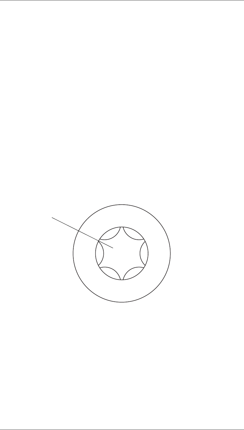
Figure 2.1 below shows a typical Torx recess head screw (actual hardware may differ
slightly from this illustration due to variations in manufacturing techniques).
Figure 2.1 Torx Screw Identification
"star" shaped recess with
six internal notches
A2.2 Mechanical M820-00
01/07/00 Copyright TEL
2.2 Pozidriv & Philips Recess Head Screws
Pozidriv and Philips recess head screws will continue to be used in T800 Series II equip-
ment in a few special applications. It is important that you use the correct type and size
screwdriver for each screw type to avoid damaging the screw head.
It is particularly important that you do not use Philips screwdrivers on Pozidriv screw
heads as the tapered driving flutes of the Philips screwdriver do not engage correctly
with the parallel-sided slots in the Pozidriv screw head. This can result in considerable
damage to the screw head if the screwdriver tip turns inside the recess.
Note: If you find you need excessive downwards pressure to keep the screwdriver
tip in the Pozidriv screw head, you are probably using the wrong type and/
or size screwdriver.
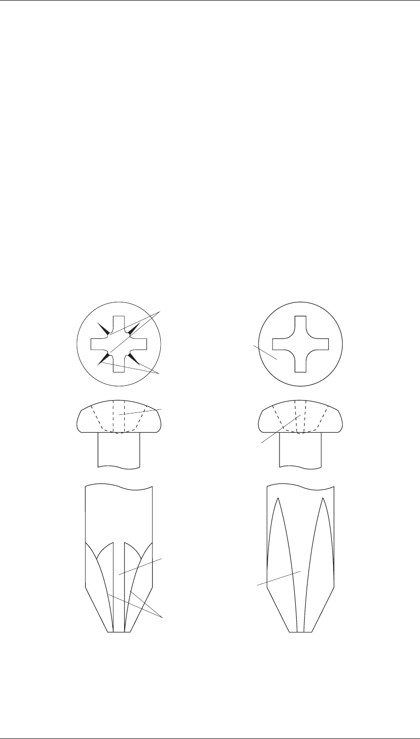
Figure 2.2 below shows the main differences between typical Pozidriv and Philips screw
heads and screwdriver tips (actual hardware may differ slightly from these illustrations
due to variations in manufacturing techniques).
Figure 2.2 Pozidriv & Philips Screw & Screwdriver Identification
driving flutes with
parallel sides
driving flutes with
tapered sides
Pozidriv Philips
internal notches
"star" markings
between slots
no special markings
slots with parallel sides
slots with tapered sides
ridges between
driving flutes

M820-00 Mechanical A2.3
Copyright TEL 01/07/00
2.3 Disassembly/Reassembly
2.3.1 Receivers/Exciters/Transmitters
To carry out alignment or change option links, you need to remove only the top cover,
i.e. the one adjacent to the front panel handle and on the opposite side to the main
D-range connector (D-range 1/PL100).
You need to remove the bottom cover to:
• access transmitter RF power transistors and many SMD components
• change solder blob links
• fit test leads to circuit block access points.
2.3.2 Power Amplifiers
You should carry out the tuning and power output level setting procedures with the
cover on.
2.4 Cover Screw Torques
Receivers/Exciters/Transmitters .. 1.36Nm/12in.lbf.
Power Amplifiers .. 0.9Nm/8in.lbf.
A2.4 Mechanical M820-00
01/07/00 Copyright TEL
2.5 Chassis & Cover Compatibility
The chassis and covers used in T800 Series II modules incorporate a number of design
changes to improve Electro-Magnetic Compatibility (EMC) performance. It is impor-
tant that only the new-design covers are fitted to the new chassis to ensure correct
mechanical fit and continued compliance with appropriate EMC Type Approval regula-
tions.
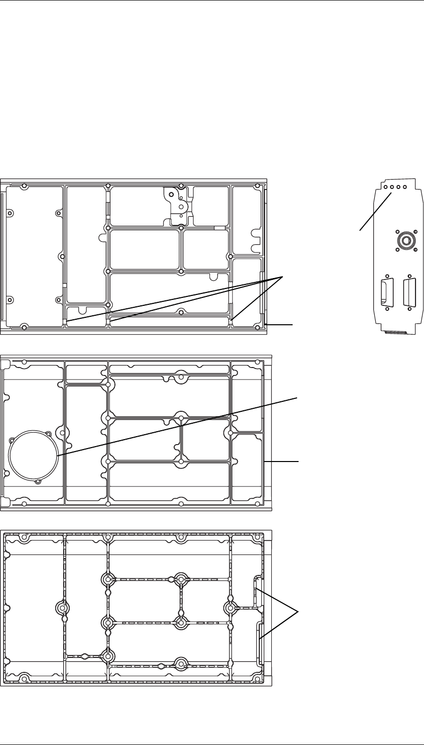
Figure 2.3 below shows some of the main features which can be used to identify the
new-design chassis and covers.
Figure 2.3 Identification Of New-Design Chassis & Covers
Top Cover
Bottom Cover
Chassis
4 holes in
rear panel
loom channel in
top of walls
groove in top
of rear wall
ridge on top
of rear wall
provision for mounting speaker
(future development)
additional walls
←To p View Rear View→
