81307_2 Ray Marine SPX 30 Commissioning And Setup Guide
User Manual: Pdf
Open the PDF directly: View PDF ![]() .
.
Page Count: 48
- SmartPilot X-Series
- Contents
- Preface
- Chapter 1: Procedures
- 1.1 Introduction
- 1.2 Commissioning procedures
- 1.3 Manual set-up
- Chapter 2: SPX system settings
- SmartPilot X-Series Specifications
- Glossary
SmartPilot
X-Series
Commissioning &
Setup Guide
for SPX-10, SPX-30,
SPX-Solenoid & SPX-CAN
Systems
Document reference: 81307-2
Date: July
2012
81307_2.book Page 1 Tuesday, July 24, 2012 8:34 AM
Raymarine, SeaTalk, SeaTalkng, SmartPilot, AutoLearn, AutoRelease, AutoTack, AutoTrim, GyroPlus and WindTrim are regis-
tered trademarks of Raymarine Ltd
© Handbook contents copyright Raymarine Ltd
81307_2.book Page 2 Tuesday, July 24, 2012 8:34 AM

Contents 3
Contents
Contents......................................................................................................................... 3
Preface .............................................................................................................................i
Safety notices ........................................................................................................... i
EMC Conformance ................................................................................................... i
Product documents ................................................................................................... i
Important .........................................................................................................ii
Limitations on pressure washing ...............................................................................ii
Warranty ...... ............................................................................................................ iii
Product disposal ......................................................................................................iii
Chapter 1:Procedures ............................................................................................... 1
1.1 Introduction .................................................................................................... 1
SeaTalk Controller differences........................................................................ 1
Requirement................................................................................................... 2
1.2 Commissioning procedures ........................................................................... 2
Dockside checks ............................................................................................ 2
Switching on ............................................................................................... 3
Checking SeaTalk and NMEA connections ................................................ 3
Checking autopilot operating sense............................................................ 4
Entering Dealer calibration mode ............................................................... 5
Setting the vessel type................................................................................ 6
Setting the drive type .................................................................................. 7
Aligning the rudder position sensor ............................................................ 7
Setting the rudder limits .............................................................................. 8
Save the new settings................................................................................. 8
Seatrial Calibration......................................................................................... 8
Important..................................................................................................... 8
EMC conformance ...................................................................................... 8
Seatrial conditions ...................................................................................... 8
Calibrating the compass ............................................................................. 9
AutoLearn ................................................................................................. 12
Commissioning complete ............................................................................. 14
1.3 Manual set-up .............................................................................................. 14
Checking SPX system operation.................................................................. 14
Response level............................................................................................. 15
Rudder gain.................................................................................................. 15
Checking................................................................................................... 15
Adjusting ................................................................................................... 16
Adjusting the counter rudder ........................................................................ 16
Checking................................................................................................... 16
Adjusting ................................................................................................... 17
AutoTrim....................................................................................................... 17
Adjusting ................................................................................................... 17
Chapter 2:SPX system settings ........................................................................... 19
2.1 Introduction .................................................................................................. 19
Calibration modes ........................................................................................ 19
Display calibration..................................................................................... 19
User calibration......................................................................................... 19
Seatrial calibration .................................................................................... 19
Dealer calibration...................................................................................... 19
Accessing the Calibration modes.................................................................. 20
81307_2.book Page 3 Tuesday, July 24, 2012 8:34 AM

4 SmartPilot X-Series Commissioning & Setup Guide
Adjusting calibration values .......................................................................... 20
2.2 Display calibration ........................................................................................ 21
RUDD BAR screen ....................................................................................... 21
HDG screen.................................................................................................. 21
Data pages .................................................................................................. 21
Setting up data pages............................................................................... 22
2.3 User calibration ........................................................................................... 23
AutoTack ...................................................................................................... 24
Setting default AutoTack angle................................................................. 24
Selecting Relative Tack ............................................................................ 24
Gybe inhibit................................................................................................... 24
Wind selection .............................................................................................. 24
WindTrim ...................................................................................................... 25
Response level............................................................................................. 25
2.4 Dealer calibration ......................................................................................... 25
Seatrial calibration lock ................................................................................ 26
Vessel type .................................................................................................. 26
Drive type ..................................................................................................... 27
Align rudder.................................................................................................. 27
Rudder limit .................................................................................................. 28
Rudder gain ................................................................................................. 28
Counter rudder ............................................................................................. 28
Rudder damping ........................................................................................... 28
AutoTrim ...................................................................................................... 29
Response level ............................................................................................ 29
Turn rate limit ................................................................................................ 29
Off course angle ........................................................................................... 30
AutoTack ...................................................................................................... 30
Gybe inhibit................................................................................................... 30
Wind selection .............................................................................................. 30
WindTrim ...................................................................................................... 30
PowerSteer................................................................................................... 31
Cruise speed ................................................................................................ 31
Latitude ........................................................................................................ 31
System reset................................................................................................. 31
2.5 System defaults ........................................................................................... 33
SmartPilot X-Series Specifications..................................................................... 35
Glossary ....................................................................................................................... 37
Contents....................................................................................................................... 39
81307_2.book Page 4 Tuesday, July 24, 2012 8:34 AM

Preface i
Contents
Preface
Safety notices
EMC Conformance
All Raymarine equipment and accessories are designed to the best industry
standards for use in the recreational marine environment. Their design and
manufacture conforms to the appropriate Electromagnetic Compatibility (EMC)
standards, but correct installation is required to ensure that performance is not
compromised.
Product documents
This document is part of a series of books associated with the Raymarine
SmartPilot X (SPX) series of autopilot systems..
WARNING: Product installation & operation
This equipment must be installed, commissioned and operated
in accordance with the Raymarine instructions provided.
Failure to do so could result in personal injury, damage to your
boat and/or poor product performance.
WARNING: Electrical safety
Make sure you have switched off the power supply before you
make any electrical connections.
WARNING: Navigational safety
Although we have designed this product to be accurate and
reliable, many factors can affect its performance. Therefore, it
should serve only as an aid to navigation and should never
replace commonsense and navigational judgement. Always
maintain a permanent watch so you can respond to situations
as they develop.
Title Part number
ST6002 SmartPilot Controller Operating Guide 81269
ST7002 SmartPilot Controller Operating Guide 81270
ST8002 SmartPilot Controller Operating Guide 81271
ST70 AutoPilot Controller - SPX System Commissioning 81287
SmartPilot Surface Mount Controller Installation Guide 87058
SPX SmartPilot System Installation Guide, SPX 10, SPX 30,
SPX Solenoid
87072
81307_2.book Page i Tuesday, July 24, 2012 8:34 AM

ii SmartPilot X-5 Wheel Installation & Setup Guide
These documents can be downloaded from www.raymarine.com/handbooks
To the best of our knowledge, the information in the product documents was correct
when they went to press. However, Raymarine cannot accept liability for any
inaccuracies or omissions in product documents.
In addition, our policy of continuous product improvement may change specifications
without notice. Therefore, Raymarine cannot accept liability for any differences
between the product and the accompanying documents.
Important
This book does not apply to the SPX-5 series of autopilots. These have their own
Installation & Setup Guides (Part Numbers 87075, 87075 and 87076).
Limitations on pressure washing
CAUTION: Do not pressure wash Raymarine products
Raymarine products must NOT be subjected to water pressures in
excess ofCFR46 / IPX6 standards (for example, as generated by
commercial high pressure washing equipment). Products subjected
to water at these high pressures may experience water intrusion and
subsequent failure.
Raymarine products are waterproofed to CFR46 / IPX6 standards, which means that
when installed and operated in accordance with the appropriate product
documentation, they can be used in most weather and sea conditions. However, any
exposure to high-pressure water that exceeds the CFR46 / IPX6 standards, on or
around Raymarine products will invalidate the warranty for those products.
Fluxgate compass installation sheet 87011
Warranty Booklet 80017
Title Part number
81307_2.book Page ii Tuesday, July 24, 2012 8:34 AM

Preface iii
Warranty
To register your new Raymarine product, please take a few minutes to fill out the
warranty card. It is important that you complete the owner information and return the
card to us to receive full warranty benefits. You can also register online at
www.raymarine.com by following the
Login or create an account
link.
Product disposal
Waste Electrical and Electronic (WEEE) Directive
The European WEEE Directive requires that waste electrical and electronic
equipment is recycled.
Products carrying the crossed out wheeled bin symbol (illustrated above)
must not be disposed of in general waste or landfill, but in accordance with local
regulations for such products.
Although the WEEE Directive does not apply to all Raymarine products, we support
its policy and ask you to be aware of the correct method for disposing of such
products.
Please contact your local dealer, national distributor or Raymarine Technical Services
for information on product disposal.
81307_2.book Page iii Tuesday, July 24, 2012 8:34 AM

iv SmartPilot X-5 Wheel Installation & Setup Guide
81307_2.book Page iv Tuesday, July 24, 2012 8:34 AM
1
Chapter 1: Procedures
WARNING: Calibration requirement
All autopilot systems must be calibrated before use.
1.1 Introduction
This chapter describes the commissioning and initial setup procedures for the
following combinations of Raymarine SmartPilot X (SPX) autopilot systems and Pilot
Controllers:
Note: This book does NOT apply to SPX-5 systems or to systems using ST70 or p70 / p70R Pi-
lot Conrollers.
If your SPX system is controlled with an ST70 Pilot Controller refer to document
81287.
If your SPX system is controlled with a p70 or p70R Pilot Controller refer to document
87132.
SeaTalk Controller differences
Minor differences in the control functions of the various SeaTalk Pilot Controller types
are as follows:
Any of these systems
SPX-10
SPX-SOL
SPX-CAN
SPX-30
or
or
or
ST6002
ST7002
ST8002
or
or
controlled by any of
these controllers
81307_2.book Page 1 Tuesday, July 24, 2012 8:34 AM

2 SmartPilot X-Series Commissioning & Setup Guide
Requirement
The commissioning procedures are mandatory and must be carried out after
installation, before an SPX system is used to steer the boat. The commissioning
procedures comprises a series of dockside safety checks and a short seatrial.
Additional setup procedures enable you to fine tune your SPX system for optimum
performance with your boat. These procedures are not mandatory and you may find
that you do not need to use them if the SPX system operates to your satisfaction after
commissioning.
1.2 Commissioning procedures
Dockside checks
The dockside checks comprise:
1. Switching on.
2. Checking SeaTalk and NMEA 0183 connections.
3. Checking autopilot steering sense.
4. Setting vessel type and drive type
5. Setting rudder limits, if rudder reference option fitted.
WARNING: Ensure safe control
For safe control of your boat, you MUST complete the dockside
checks before starting the initial seatrial.
With the boat safely tied up, complete the following dockside checks.
ST6002 Controller ST7002 Controller ST8002 Controller
•standby & auto
function keys
•+1, -1, +10 & -10 course
change keys
•disp & track extended
function keys
•standby & auto
function keys
•+1, -1, +10 & -10 course
change keys
•resp, track, mode, res’m,
disp, up & down extended
function keys
•standby & auto
function keys
•Rotary course change con-
trol
•resp, track, mode, res’m,
disp, up & down extended
function keys
D6400-1
D6401-1
D6402-1
81307_2.book Page 2 Tuesday, July 24, 2012 8:34 AM
Chapter 1: Procedures 3
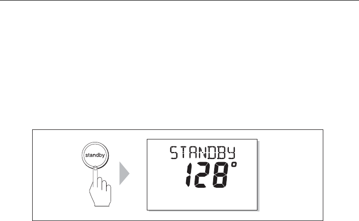
Switching on
1. When you have installed your SPX system, switch on the main power breaker.
2. If the SmartPilot controller and computer are active, the controller will beep, show
the controller type for a few seconds will show the
STANDBY
screen.You may see
a
CALIBRATE REQUIRED
message. This is displayed for a short time ifeither:
• the vessel type is not selected.
• the compass is not calibrated.
These will be calibrated later in this chapter.
3. Check that the
STANDBY
screen displays a live compass heading.
Troubleshooting
• If the Pilot Controller does not beep or the display is blank, check the fuse/circuit
breaker and the SeaTalk fuse in the SPX Course Computer.
• If the display shows the
SEATALK FAIL
or
NO DATA
alarm message, check the
SeaTalk connections.
• If the
STANDBY
screen does not display a live compass heading, check the sensor
connections.
Note: The autopilots built-in gyro requires a few minutes to stabilize after power on. During this
time the heading may appear to drift until the gyro has stabilized.
Checking SeaTalk and NMEA connections
SeaTalk connections
If you have connected the Pilot Controller to other SeaTalk instruments or controllers,
check the links as follows:
1. Select display lighting level 3 (
LAMP 3)
on one of the other SeaTalk instruments or
controllers.
2. Check that the Pilot Controller display lights are on. If the lights are not on, check
the SeaTalk cabling between the Pilot Controller and the other units.
NMEA navigator connections
If you have connected the SPX system to a NMEA navigator, check the links by
displaying the default navigation data pages on the Pilot Controller:
1. Press
disp
to display the first data page (XTE), and check that this page shows the
expected data.
2. Press
disp
again to check each successive data page (BTW, DTW etc)
If the display shows dashes instead of data values, ensure:
• The navigator is switched on and transmitting an active waypoint.
• The navigator is configured to transmit the required data format
D10524-1
TRUE
81307_2.book Page 3 Tuesday, July 24, 2012 8:34 AM
4 SmartPilot X-Series Commissioning & Setup Guide
• There is not a cabling error. Check for open circuit, short circuit or reversed wires
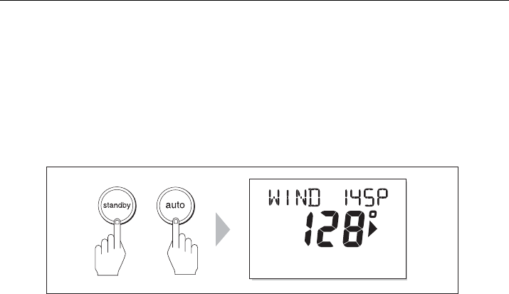
Wind instrument connections
If you have connected the SmartPilot to a SeaTalk or NMEA wind instrument, check
the links as follows:
1. Simultaneously press
standby
and
auto
.
2. Check that the Pilot Controller displays the Wind Vane mode screen, with the
locked wind angle and locked heading. If WIND mode is not displayed, the SPX
system is not receiving wind data. Check the wind instrument and connections.
Checking autopilot operating sense
If the rudder reference option is not fitted, ignore this step and proceed from Generic
checks, below.
If the rudder reference option is fitted:
1. Turn the wheel manually to starboard.
2. Check that the rudder bar on the controller moves to starboard.
If the rudder bar display moves the wrong way:
i. Turn off the power.
ii. Reverse the red and green wires connected to the
RUDDER
inputs on the
SPX Course Computer.
iii. Switch on the power and re-check.
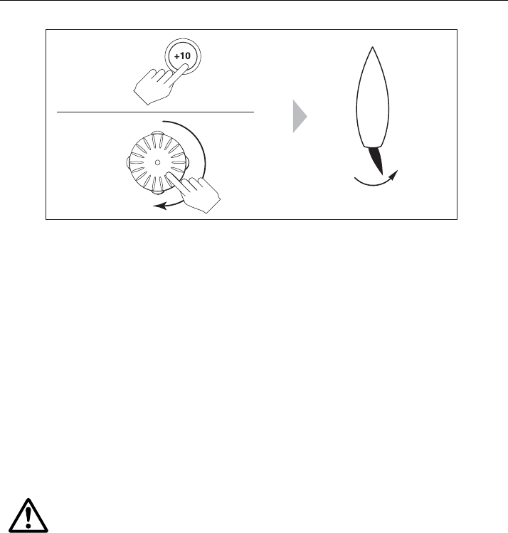
Generic checks
1. Manually center the wheel, then press
auto
so the SPX system is in Auto
mode.Check that the display shows
AUTO
.
Be ready to press standby if the rudder moves hardover.
2. Press the +10 key once or turn the rotary control ½ turn clockwise.
MAG
D10532-1
+
81307_2.book Page 4 Tuesday, July 24, 2012 8:34 AM
Chapter 1: Procedures 5
3. Check that the rudder moves to starboard a few degrees, then stops. If the rudder
drives hardover, immediately press
standby
to prevent further rudder movement
4. If the rudder moves to port or the rudder drives hardover:
i. Press
standby.
ii. Turn off the power.
iii. Reverse the motor wires connected to the SPX Course Computer.
iv. switch on the power and re-check.
Note: If the rudder overshoots and has to drive back or starts to hunt back and forth, you will
need to increase the rudder damping level manually (See page 28).
Entering Dealer calibration mode
To proceed with the commissioning, you need to enter Dealer Calibration, to set :
• Vessel type.
• Drive type.
• Rudder indicator (if rudder reference option is fitted).
• Rudder limits (if rudder reference option is fitted).
To enter the Dealer calibration mode:
1. Ensure the SPX system is in Standby mode.
2. Referring to the following table, use the procedure appropriate to the Pilot
Controller you are using to enter Dealer calibration mode.
WARNING: Use Dealer calibration correctly
Improper use of Dealer calibration can seriously impair the SPX
system performance and therefore adversely affect the
steering capability. Do not change Dealer calibration settings
other than as described in the product documentation.
D10745-1
ST6002
ST7002
ST8002
½
turn
81307_2.book Page 5 Tuesday, July 24, 2012 8:34 AM
6 SmartPilot X-Series Commissioning & Setup Guide
Note: For more information on settings and calibration modes, refer to Section Chapter 2:,
SPX system settings
Setting the vessel type
When you select a vessel type, the SPX system automatically selects appropriate
default values for various other calibration settings.
Some of these settings will be checked later in this procedure and others should not
require any adjustment. The default values for each vessel type are listed on page 33.
To set the vessel type:
1. Use
disp
to scroll through the Dealer calibration pages until the display shows
either
VESSEL
or one of the vessel types (e.g.
DISPLACE
).
2. Use
-1
or
+1
, or the
rotary control
to select your vessel type:
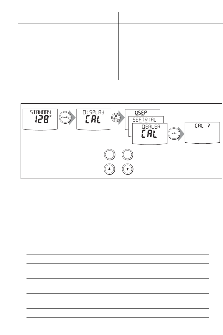
ST6002 Controllers ST7002 and ST8002 Controllers
1 Press and hold
standby
for two seconds
to enter the Calibration mode
2 When the screen shows
DISPLAY CAL
,
press
disp
until you see the
DEALER CAL
screen
3Press
auto
: the display will change to
CAL?
4 Simultaneously press -1 and +1 to enter
Dealer calibration mode
1 Press and hold
standby
for two seconds to
enter the Calibration mode
2 When the screen shows
DISPLAY CAL
,
press
disp
or the up arrow or the down
arrow, until you see the
DEALER CAL
screen
3Press
auto
: the display will change to
CAL?
4 Simultaneously press -1 and +1 (on the
ST7002) or the up and down arrows (on the
ST8002), to enter Dealer calibration mode
Options
DISPLACE
Power-driven boats which do not plane
(Typically below 15 kts top speed)
SEMI DISPLACE
Faster power-driven boats which do not plane
(Typically 15-20 kts top speed)
PLANING
Planing boats with inboard engine(s) and shaft drives
(NOT boats with outdrives)
STERN DRV
Boats with outdrives or outboard engines
WORK BOAT
Commercial tugs, fishing vessels, etc
SAIL BOAT
Sailing boat
At the CAL ? screen, press + together to enter DEALER CAL
2 sec x3
-1 +1
or
D10746-1
(ST8002 only)
+
81307_2.book Page 6 Tuesday, July 24, 2012 8:34 AM
Chapter 1: Procedures 7
3. Press
disp
to select the appropriate type of boat and move to the next calibration
option.
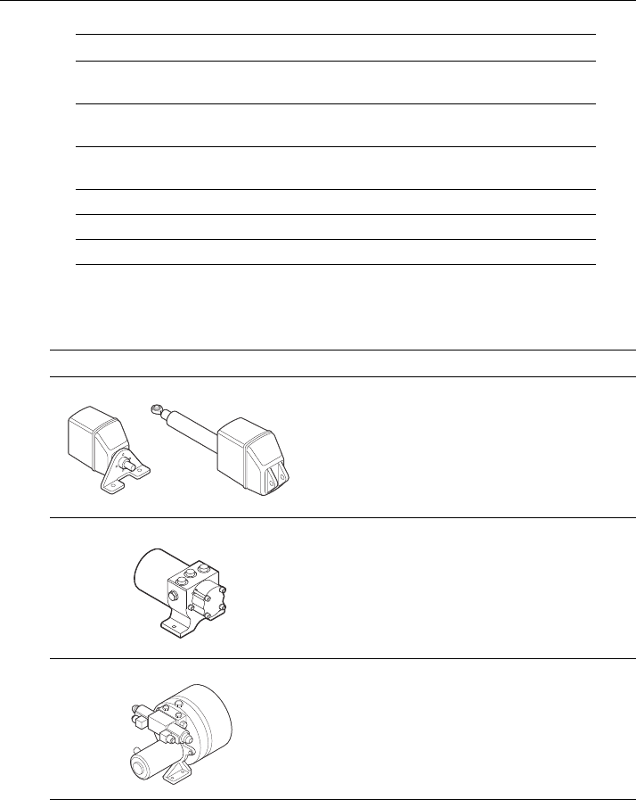
Setting the drive type
SPX systems will operate with a range of steering drives, as follows:
Select the appropriate drive type as follows.
1. With the SPX system still in Dealer calibration, use
disp
to scroll through the
calibration pages until you reach the
DRIVE TYP
page.
2. Use
-1
or
+1,
or the
rotary control
to select the appropriate drive type:
3. Press
disp
to select the drive type and move to the next calibration option.
Aligning the rudder position sensor
Carry out this procedure only if the rudder reference option is fitted. If the rudder
reference option is not fitted, ignore this procedure.
If the rudder reference option is fitted:
1. With the SmartPilot still in Dealer calibration, press
disp
to scroll through the
calibration pages until you reach the
ALIGN RUD
page.
2. Use the wheel to center the rudder.
3. Use
-1
and
+1
or the
rotary control
to adjust the rudder bar so it is positioned at
the center.
The maximum adjustment available is ±9°. If the offset is beyond these limits, you
will need to physically adjust the alignment of the sensor.
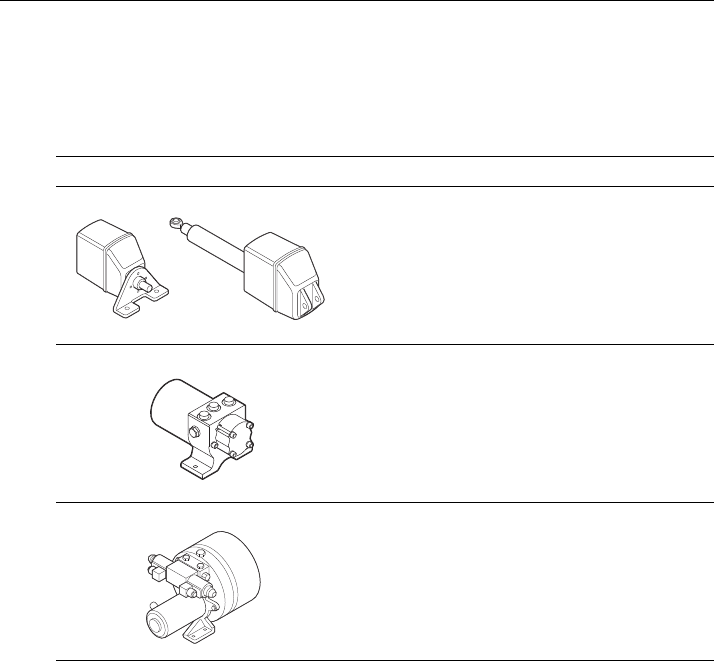
Drive Drive Type Setting
Drive Type 3
Linear
Rotary
Typically found on yachts
I/O (stern)
Found on Powerboats
Drive Type 4
Hydraulic reversing pump
Used on yachts and powerboats with hydraulic
steering
Drive Type 5
Constant running hydraulic pumps. Controlled by
solenoid valves
Found on light commercial and larger boats
D6404-1
D6405-1
D6406-1
81307_2.book Page 7 Tuesday, July 24, 2012 8:34 AM

8 SmartPilot X-Series Commissioning & Setup Guide
4. Press
disp
to select the correct alignment and move to the next calibration option.
Note: Alternatively, you can zero the rudder bar with the boat underway during the initial seatri-
al, by manually steering a straight course then accessing the
ALIGN RUD
screen in Seatrial Cal-
ibration to adjust the offset.
Setting the rudder limits
Carry out this procedure only if the rudder reference option is fitted. If the rudder
reference option is not fitted, ignore this procedure.
If the rudder reference option is fitted:
1. With the SmartPilot still in Dealer Calibration press
disp
to scroll through the
calibration pages until you reach the
RUD LIMIT
page.
2. Turn the wheel to move the rudder:
• to the port end stop and note the angle on the rudder bar
• to the starboard end stop and note the angle on the rudder bar
3. Use
-1, +1, -10
and
+10
or the
rotary control
to set the rudder limit to 5° less
than the lowest angle you have noted.
4. Press
disp
to select the new value and move to the next calibration option.
Save the new settings
When you have adjusted the above settings, hold down
standby
for two seconds, to
save your changes, leave Dealer calibration and return to the Standby mode
Seatrial Calibration
When you have completed the dockside checks, carry out a Seatrial calibration, to
calibrate the compass and set up the autopilot steering characteristics.
Before commencing the seatrial:
• The dockside calibration must have been successfully completed.
• There must be no EMC problems.
The Seatrial procedures are:
• Compass calibration.
• Using AutoLearn to set the SPX system steering characteristics.
Important
If you need to return to manual steering at any time during a Seatrial or any other
procedure, press the standby button. NEVER compromise vessel safety.
EMC conformance
Always check the installation before going to sea to make sure that it is not affected by
radio transmissions, engine starting etc.
Seatrial conditions
The seatrial must be carried out only:
• In conditions of light wind and calm water.
• In waters that are clear of any obstructions, so the boat has plenty of clear space
to maneuver.
81307_2.book Page 8 Tuesday, July 24, 2012 8:34 AM
Chapter 1: Procedures 9
In order to achieve optimum autopilot performance, course over ground (COG),
speed over ground (SOG) and latitude (LAT) data must be available to the SPX
system (e.g. on SeaTalk). Ensure that the equipment providing this information (e.g.
GPS), is switched on and fully operational, before starting a Seatrial.
Calibrating the compass
Note: This section does not apply if you have connected an NMEA compass to your SPX sys-
tem. Refer to the handbook supplied with the NMEA compass for information about calibration.
The compass calibration procedures are:
• Swinging the compass.
• Aligning the compass.
Swinging the compass
The magnetic deviation correction procedure (commonly called “swinging the
compass”) involves turning your boat in slow circles so the autopilot can automatically
determine the deviation and apply any correction required. The correction procedure
reduces deviation errors to a few degrees.
As magnetic deviation can cause significant compass errors on your boat, you MUST
complete the compass swing before any other seatrial procedure.
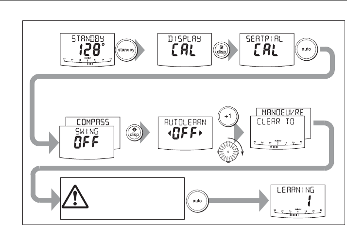
To swing the compass:
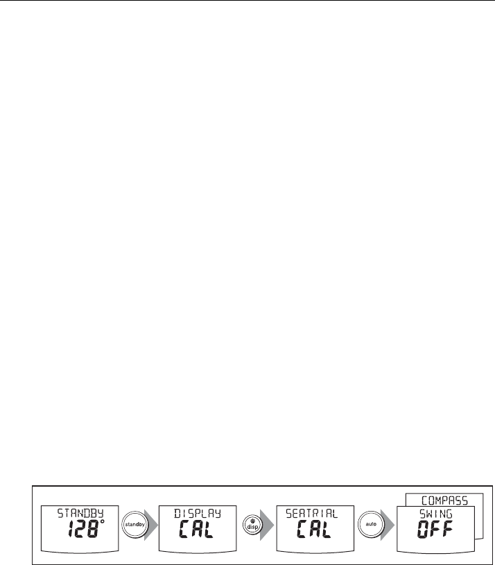
1. With the SPX system in Standby mode, enter Seatrial calibration as follows:
i. Hold down
standby
for two seconds to enter Calibration mode.
ii. When you see the
DISPLAY CAL
screen, press
disp
until you see the
SEATRIAL CAL
screen.
iii. Press
auto
to enter Seatrial calibration.
Note: If you cannot access Seatrial calibration, you need to disable the calibration lock. This can
be found in Dealer calibration (see page 26).
2. Use
disp
as necessary, to move through the Seatrial Calibration items until you
see
SWING COMPASS.
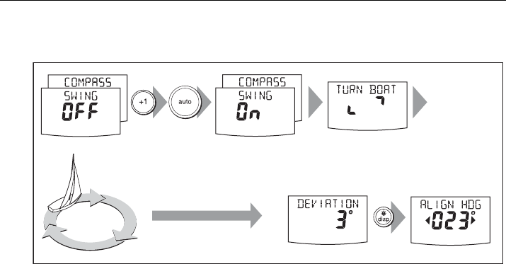
3. When you are ready to start, press
+1
, or turn the
rotary control
clockwise, to
select
SWING COMPASS ON
. On ST8002 systems, you must then press
auto
to
start the compass swing.
The controller will display
TURN BOAT
indicating the start of the calibration
process.
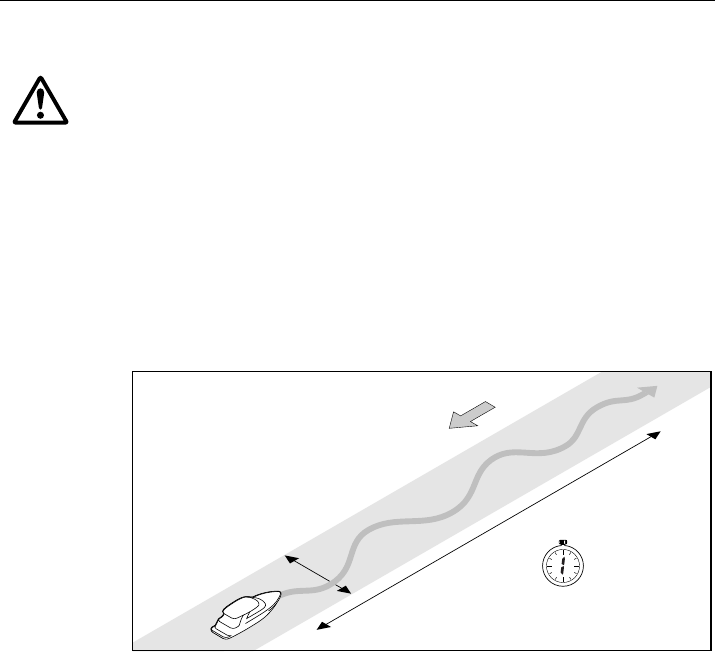
4. Start slowly turning the boat in circles (keeping the boat’s speed below 2 knots).
You will need to complete at least two circles, taking at least 2 minutes to complete
each 360°:
If you turn the boat too quickly, the display will show a
TOO FAST
message. If this
occurs, apply less helm to turn in a larger circle.
2 sec x2
D10541-1
81307_2.book Page 9 Tuesday, July 24, 2012 8:34 AM
10 SmartPilot X-Series Commissioning & Setup Guide
Note: If necessary, you can quit the correction process by pressing
standby
or
disp
. If you then
want to repeat the deviation correction, return to the
SWING COMPASS
screen.
5. Continue slowly turning the boat until the controller beeps and displays the
DEVIATION
screen. This indicates that the SPX system has completed the
deviation correction.
Note: This screen shows the maximum deviation encountered over 360° (not as an east/west
value).
If the deviation figure exceeds 15° or the display shows no deviation value, the
compass is being affected by ferrous objects on your boat. You should move the
compass to a better location. Higher deviation figures are acceptable on steel boats.
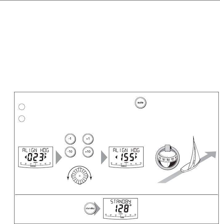
Aligning the compass heading
Once the deviation is displayed, press
disp
to move to the Heading Alignment
(
ALIGN HDG
).page.
1. Manually steer the boat on a steady course at a speed sufficient to hold the
course.
D10542-1
Turn boat in slow circles so:
• boat's speed stays below 2 knots
• each circle takes at least 2 minutes
Minimum of
2 circles Keep turning the boat until
you see the DEVIATION screen
Start
turning boat
Autopilot heading
81307_2.book Page 10 Tuesday, July 24, 2012 8:34 AM
Chapter 1: Procedures 11
2. If you have a GPS connected to your SPX system:
• Increase the boat speed to more than 3 knots
• Press
auto
. The SPX system will then set the heading to agree with the COG
(course over ground) heading received from the GPS
As many factors can cause a difference between heading and COG, you must fine-
tune the heading alignment so it matches the boat’s steering compass (or a known
transit bearing). To do this:
1. Use
-1,
+1
,
-10
and
+10
or the
rotary control
to adjust the displayed heading
until it matches the boat’s steering compass (or a known transit bearing).
2. Hold down
standby
for 2 seconds to exit Seatrial calibration and save the new
compass settings.
Although the compass calibration removes most of the alignment error, small errors
(a few degrees) may remain. Once you have completed the initial compass
calibration, you can make further adjustments to the alignment without having to
swing the compass again.
Check the heading reading against a number of known headings, plot a deviation
curve, and determine the heading alignment value that will give the lowest average
alignment error. You can then enter this value on the Heading Alignment screen, as
described above.
If the average heading error is more than 5°, you should perform the compass
deviation correction procedure again, circling more slowly and in more favorable
conditions.
2 sec
D6320-2
Align the autopilot heading
a
b
Save changes To:
• save deviation correction
• save heading alignment
• return to STANDBY mode
Autopilot heading Steering compass
=
Known
heading
or
or
Adjust the autopilot heading so it shows the same value as the boat's steering compass
Coarse adjustment: If COG is available from GPS, press to set autopilot heading to
COG value, then fine tune manually (see below).
Fine adjustment: If COG is not available (or after setting heading to COG),
align autopilot heading manually:
ST6001, ST7001, ST6002 & ST7002
ST8001 & ST8002
81307_2.book Page 11 Tuesday, July 24, 2012 8:34 AM
12 SmartPilot X-Series Commissioning & Setup Guide
AutoLearn
The next stage of the Seatrial is to carry out an AutoLearn routine. AutoLearn is a self-
learning calibration feature that automatically adjusts rudder gain, counter rudder and
AutoTrim for optimum performance for your boat.
If you need to return to manual steering at any time during an AutoLearn routine or any
other procedure, press the
standby
button. NEVER compromise vessel safety.
Carry out an AutoLearn as follows:
1. Ensure you have sufficient sea room to complete the AutoLearn:
2. Access the
AUTOLEARN
screen in Seatrial calibration:
i. From Standby mode, hold down
standby
for 2 seconds, then press
disp
twice
to see the
SEATRIAL CAL
screen.
ii. Press
auto
to enter Seatrial calibration, then press
disp
four times to see the
AUTOLEARN
screen.
3. Prepare to start the AutoLearn:
•power boats: steer straight ahead (rudder centered). For non-planing boats,
set a comfortable cruising speed. For planing boats set the speed so the boat
is just planing.
•sail boats: with the sails down, steer straight ahead (rudder centered) and
motor the boat at typical cruising speed.
4. If conditions are not calm, head into the wind and waves.
WARNING: Ensure there is enough clear sea space
The AutoLearn process takes the boat through a number of
maneuvers, which can result in sudden, sharp turns, especially
when the AutoLearn function is run on more maneuverable
boats. Therefore, ensure there is a significant amount of CLEAR
SEA SPACE in front of the boat, before starting an AutoLearn
process.
At least 0.25 nm (500 m) of clear sea space
At least 0.04 nm (100 m)
of clear sea space
D5495-2
1 minute
(approximately)
Wind
81307_2.book Page 12 Tuesday, July 24, 2012 8:34 AM
Chapter 1: Procedures 13
5. When you are ready to proceed:
• On ST6002 and ST7002 systems, press
+1
.
• On ST8002 systems, turn the
rotary control
clockwise, then press
auto
.
6. The screen will then show the
CLEAR TO MANEUVER
message. Ensure it is safe
to continue, then press
auto
to start the AutoLearn maneuvers:
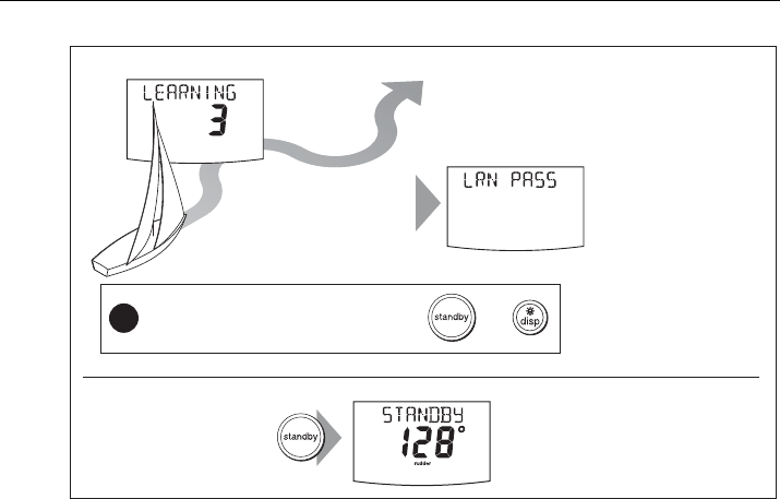
• The boat will start a series of zig-zag turns and the display will show
LEARNING
with a number to indicate the current AutoLearn stage. This number increases
as AutoLearn progresses.
• A typical AutoLearn completes within 7 to 27 steps (depending on boat
characteristics and sea conditions).
Note: To cancel an AutoLearn, press
standby
or
disp
.
7. When the SPX system has finished learning, the controller will beep and display
either
LRN PASS
or
LRN FAIL
:
•
LRN PASS
= AutoLearn completed successfully
•
LRN FAIL
= AutoLearn was not successful, so should be repeated. A failure
code will also be displayed:
1
= AutoLearn has not been carried out
2
= AutoLearn failed, due to manual interruption
4
= AutoLearn failed, probably due to drive or compass failure
5
= AutoLearn failed, probably due to motor current limiting.
6
= AutoLearn failed, probably due to boat spinning.
8. If the AutoLearn was successful, hold down standby for 2 seconds to store the
new settings.
2 sec x2
x4
D8641-1
• steer straight ahead at cruising speed
(planing boats – just on the plane)
• head into wind and waves
AutoLearn in progress
Prepare for AutoLearn
Start
AutoLearn
Enter Seatrial calibration
or
CHECK!
Before proceeding, ensure
you have sufficient clear
sea space
81307_2.book Page 13 Tuesday, July 24, 2012 8:34 AM
14 SmartPilot X-Series Commissioning & Setup Guide
Commissioning complete
Your SPX system is now commissioned and ready for use.
After you have used your SPX system, you may decide to change the value of some
parameters to improve pilot performance with your boat. If you feel this is necessary,
use the appropriate procedures under Manual setup, below.
1.3 Manual set-up
Checking SPX system operation
Before manually adjusting any settings, familiarize yourself with basic SPX system
operation, as follows:
1. Steer onto a compass heading and hold the course steady at a normal cruising
speed. If necessary, steer the boat manually for a short time to check how the boat
steers.
2. Press
auto
to lock onto the current heading. The SPX system should hold the
locked heading in calm sea conditions.
3. Use
-1
,
+1
,
-10
and
+10
and observe how the SPX system alters the course to port
and starboard.
4. Press standby to return to manual steering.
If you feel you need to fine tune the SPX system performance, you can do so by using
one or more of the procedures below to adjust:
• Response level.
• Rudder gain.
• Counter rudder
• AutoTrim.
2 sec
D10546-1
AutoLearn successful
If you need to cancel the AutoLearn, press or
Note: If you see a
LRN FAIL message,
press disp to return to
the AUTOLEARN screen
then repeat from Step 2
After
7 to 27
steps
!
Boat completes AutoLearn
Save new settings To:
• save AutoLearn calibration settings
• return to STANDBY mode
81307_2.book Page 14 Tuesday, July 24, 2012 8:34 AM

Chapter 1: Procedures 15
Over time you may wish to repeat these adjustments using a range of sea conditions
and headings to achieve optimum all-round performance for your particular vessel
and preferences.
Adjust these settings when motoring your boat at cruising speed.
Response level
The principal method of adjusting the performance of SPX systems is by changing the
response level. This controls the relationship between the system’s course keeping
accuracy and the amount of helm/drive activity.
To temporarily change the response level:
1. Press
-1
and
+1
or
resp
to access the
RESPONSE
screen (see page 25).
2. Use the
-1
or
+1
key or the up
and down arrow
keys to adjust the setting.
3. Press
disp
to confirm the change
Rudder gain
Boats can vary widely in their response to helm, and by adjusting the rudder gain you
can change the steering characteristics of the SPX system. Rudder gain is a measure
of how much helm the SPX system applies to correct course errors – higher settings
mean more rudder is applied.
Checking
Complete the following test to determine whether the rudder gain is set correctly:
1. Set
RESPONSE
to level 5 (see above).
2. Motor your boat at a typical cruising speed in clear water.
It is easier to recognize the steering response in calm sea conditions where wave
action does not mask steering performance.
3. Press
auto
to enter Auto mode, then alter course by 40°:
• If the rudder gain is adjusted correctly, the 40° course change should result in
a crisp turn followed by an overshoot of no more than 5°.
• If the rudder gain setting is too high, the 40° course change will result in a
distinct overshoot of more than 5° and there may be a distinct ‘S’ in the course,
as at (A).
Correct this oversteer by reducing the rudder gain setting
Screen Text Effect on operation
RESPONSE 1-3 This setting minimizes the amount of rudder activity but may compro-
mise short-term course keeping accuracy,
RESPONSE 4-6 This setting gives good course keeping with crisp, well controlled turns
under normal operating conditions.
RESPONSE 7-9 This setting provides the tightest possible course keeping and greatest
rudder activity. This can lead to a rough passage in open waters as the
SPX system may fight the sea.
81307_2.book Page 15 Tuesday, July 24, 2012 8:34 AM
16 SmartPilot X-Series Commissioning & Setup Guide
• If the rudder gain is too low, the boat’s performance will be sluggish – it will take
a long time to make the 40° turn and there will be no overshoot (B).
Correct this understeer by increasing the rudder gain setting.
Adjusting
To adjust the rudder gain:
1. Access the
RUDD GAIN
screen in Dealer calibration (see page 28).
2. Use the
-1
or
+1
keys or the
rotary control
to adjust the rudder gain.
3. Hold down
standby
for 2 seconds to save the changes.
4. Press
auto
to check SPX system performance in Auto mode.
Adjusting the counter rudder
Counter rudder is the amount of rudder the SPX system applies to try to prevent the
boat from yawing off course. Higher counter rudder settings result in more rudder
being applied.
Checking
To check the counter rudder setting
1. Set
RESPONSE
to level 5 (see above).
2. Motor your boat at cruising speed in clear water.
3. Press
auto
to switch the SPX system to Auto mode, then make a 90° course
change:
• When gain and counter rudder are both set correctly, the boat performs a
smooth continuous turn with minimal overshoot.
• If the counter rudder is too low, the boat will still overshoot.
• If counter rudder is too high, the boat will ‘fight the turn’ and make a series of
short, sharp turns: this results in a very ‘mechanical’ feel as the boat changes
course.
New
heading
New
heading
A
New
heading
B
Correct
rudder gain
Rudder gain
too high
Rudder gain
too low
D3262-3
81307_2.book Page 16 Tuesday, July 24, 2012 8:34 AM

Chapter 1: Procedures 17
Adjusting
To adjust the counter rudder:
1. Access the
COUNT RUD
screen in Dealer calibration (see page 28).
2. Use
-1
or
+1
or the
rotary control
to adjust the counter rudder.
3. Hold down
standby
for 2 seconds to save the changes.
4. Press
auto
to check the SPX system performance in Auto mode.
AutoTrim
You may also need to adjust the AutoTrim setting. AutoTrim determines how quickly
the SPX system applies ‘standing helm’ to correct for trim changes caused, for
example, by changes in the wind load on the sails or superstructure, or an imbalance
of engines.
Increasing the AutoTrim level reduces the time the SPX system takes to get back onto
the correct course, but makes the boat less stable. If the SPX system:
• Gives unstable course keeping and the boat ‘snakes’ around the desired course,
decrease the AutoTrim level
• Hangs off course for excessive periods of time, increase the AutoTrim level
Adjusting
Before attempting to adjust the AutoTrim setting, ensure you have sufficient
experience using the SPX system.
On sail boats you can only evaluate the effect of AutoTrim while under sail.
If you need to adjust AutoTrim, go up one level at a time and use the lowest acceptable
value. The possible settings range from
OFF
(no trim correction) to
4
(fastest trim
correction).
To adjust the AutoTrim:
1. Access the
AUTOTRIM
screen in Dealer calibration.mode (see page 29).
2. Use
-1
or
+1
or the rotary control, to adjust the AutoTrim level.
3. Hold down
standby
for 2 seconds to save the changes.
4. Press
auto
to check the SPX system performance in Auto mode.
81307_2.book Page 17 Tuesday, July 24, 2012 8:34 AM

18 SmartPilot X-Series Commissioning & Setup Guide
81307_2.book Page 18 Tuesday, July 24, 2012 8:34 AM

19
Chapter 2: SPX system settings
2.1 Introduction
This chapter describes the SPX system calibration settings and factory default
settings. The calibration settings can be adjusted to best suit your operating
requirements, but as many will have been adjusted to optimum values when
commissioning the system, they should not require further change.
If you change the calibration settings after the SPX system has been commissioned,
you do not need to repeat the commissioning process. However, DO NOT manually
adjust autopilot settings before the commissioning procedures in Chapter 2have
been completed.
Calibration modes
There are four calibration modes, namely Display calibration, User calibration,
Seatrial calibration and Dealer calibration.
Each calibration mode uses a series of screens to set calibration values.
Display calibration
The items in Display calibration affect the SPX system Pilot Controller. They are
stored in the controller and do not affect any other controllers connected through
SeaTalk.
You can adjust the Display calibration settings as often as necessary – for example, to
add or change information displayed on data pages.
User calibration
The User calibration mode includes settings that you may need to adjust on a regular
basis to respond to changing conditions.
Seatrial calibration
The Seatrial calibration mode is used ONLY when commissioning your SPX system,
as described in Chapter 3, so is not described again here. Do not access Seatrial
calibration during normal operation.
Dealer calibration
The Dealer calibration mode includes items that have a significant impact on
operation and can affect your boat’s safety.
After you have completed the initial installation and seatrial, you should not normally
need to alter the Dealer calibration values.
81307_2.book Page 19 Tuesday, July 24, 2012 8:34 AM
20 SmartPilot X-Series Commissioning & Setup Guide
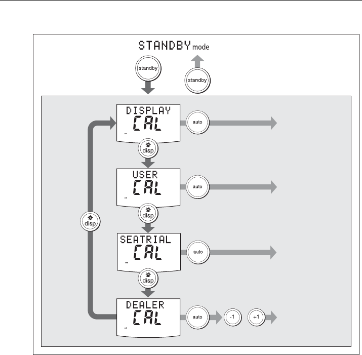
Accessing the Calibration modes
Adjusting calibration values
To adjust calibration values:
1. Access the required calibration mode (refer to the diagram above).
2. Press
disp
to scroll through the available options. To view the previous option,
press and hold
disp
for 1 second.
3. Use
-1
,
+1, -10
and
+10
to change the values
When you have made all required changes, press and hold
standby
for 2 seconds to
save changes and exit.
+
Accessing
Calibration Modes
2 seconds 2 seconds
(saves changes)
Calibration
Modes
to enter seatrial
calibration mode
D10647-1
to enter dealer
calibration mode
to enter display
calibration mode
to enter user
calibration mode
CAL ?
81307_2.book Page 20 Tuesday, July 24, 2012 8:34 AM

Chapter 2: SPX system settings 21
2.2 Display calibration
Display calibration provides settings to adjust the information displayed on the Pilot
Controller.
RUDD BAR screen
This screen gives you access to the other Display calibration screens.
HDG screen
You can choose whether to use magnetic or true heading data values. The options
are:
•
HDG MAG
- Magnetic heading. If you select this, the screen will indicate
MAG
for
heading values, during normal operation.
•
HDG TRUE
- True heading. If you select this the screen will indicate
TRUE
for
heading values, during normal operation.
Data pages
The Pilot Controller has fifteen user-configurable data pages. Each data page can be
configured to display SeaTalk/NMEA data, which can be viewed during normal
operation.
D10602-1
or
or
To adjust values
2 seconds
(save changes)
Data pages
Press disp
for next page
Accessing Display
Calibration
Display Calibration
The RUDD BAR parameters are
adjustable only if the rudder
reference transducer option is fitted
81307_2.book Page 21 Tuesday, July 24, 2012 8:34 AM

22 SmartPilot X-Series Commissioning & Setup Guide
The default data page settings are:
Setting up data pages
When setting up your data pages, we recommend that you:
• Set data pages you do not need to
NOT USED
, as these will then not be displayed
during normal operation, leaving just the data pages that you do want for you to
scroll to.
• Retain the
BTW
and
DTW
data pages. If your SPX system receives a man
overboard (MOB) message, these data pages will show the bearing and distance
to the MOB location.
.
Data Page Default Setting
1
XTE
(Cross Track Error)
2
BTW
(Bearing to Waypoint) - see Note below
3
DTW
(Distance to Waypoint) - see Note below
4
RESPONSE
Remaining pages
NOT USED
(see Setting up data pages below)
Available Data Pages Displayed as
Speed Knots
SPEED KTS
Log
LOG XXXX
.X
Trip
TRIP XXX.X
Average Speed
AV. SPD
Wind Direction e.g.
WIND PORT
Wind Speed
WIND KTS
Depth Metres
DEPTH M
- see Note below
Depth Feet
DEPTH FT
- see Note below
Depth Fathoms
DEPTH FA
- see Note below
Heading
HEADING
Water Temperature, Degrees C
WATER °C
- see Note below
Water Temperature, Degrees F
WATER °F
- see Note below
Course Over Ground
COG
Speed Over Ground, Knots
SOG KTS
Cross Track Error
XTE
Distance to Waypoint
DTW
81307_2.book Page 22 Tuesday, July 24, 2012 8:34 AM
Chapter 2: SPX system settings 23
Note: There are 3 depth data pages (meters, feet and fathoms) and 2 water temperature data
pages (°C and °F). The SPX system will display the depth data or water temperature in the units
defined by the data page you select.
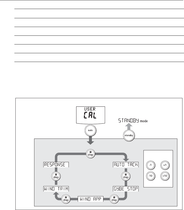
2.3 User calibration
For information on how to access User calibration, see Accessing the Calibration
modes, page 20.
The User calibration mode includes settings that you may need to adjust on a regular
basis to respond to changing conditions.
Bearing to Waypoint
BTW
Rudder Gain
RUDD GAIN
Response
RESPONSE
Watch
WATCH
- used to control the Watch timer
Universal Time Coordinated
UTC
Available Data Pages Displayed as
D10506-1
or
or
To adjust values
2 seconds
(save changes)
Accessing User Calibration
User Calibration
81307_2.book Page 23 Tuesday, July 24, 2012 8:34 AM

24 SmartPilot X-Series Commissioning & Setup Guide
AutoTack
Use this screen to select how the vessel performs when using AutoTack. You can
either:
• Set a default AutoTack angle. This is the angle through which the boat will turn
when an AutoTack is performed.
or
• Select Relative Tack operation. With Relative Tack selected, the apparent wind
angle when AutoTack is initiated, is mirrored the other side of the wind, on the
opposite tack.
Setting default AutoTack angle
To set the required AutoTack angle:
• If the SPX system is receiving wind information, set the AutoTack angle to the
required change of heading.
• If the SPX system is not receiving wind information, set the AutoTack angle to 20°
greater than the actual required change of heading.
For example, to tack through 80° (i.e when sailing at 40° to the wind), set the
AutoTack angle to 100°.
Selecting Relative Tack
To select Relative Tack, use
-1
and
-10
, to reduce the tack angle value to 30°. This
action selects Relative Tack and the screen displays
rEL
, to indicate this.
Gybe inhibit
With gybe inhibit on:
• You will be able to perform an AutoTack into the wind
• The SPX system will prevent the boat from performing an AutoTack away from the
wind, to prevent accidental gybes,
With gybe inhibit off, you can perform an AutoTack into or away from the wind.
Wind selection
This screen determines whether the boat steers to apparent or true wind in Wind Vane
mode.
Screen Text Options
AUTO TACK
40° to 125° in 1° steps
Screen Text Options
GYBE STOP
ON (Default) = Gybe inhibit on (gybes prevented)
OFF = Gybe inhibit off (gybes permitted)
Options
WIND APP
(Default) SPX system steers to apparent wind angle
WIND TRUE
SPX system steers to true wind angle
81307_2.book Page 24 Tuesday, July 24, 2012 8:34 AM

Chapter 2: SPX system settings 25
WindTrim
WindTrim controls how quickly the SPX system responds to changes in the wind
direction. Higher wind trim settings will result in a system that is more responsive to
wind changes.
Response level
This sets the default SPX system response level. The response level controls the
relationship between course keeping accuracy and the amount of helm/drive activity.
You can make temporary changes to response during normal operation, as described
in the Pilot Controller Operating Guide.
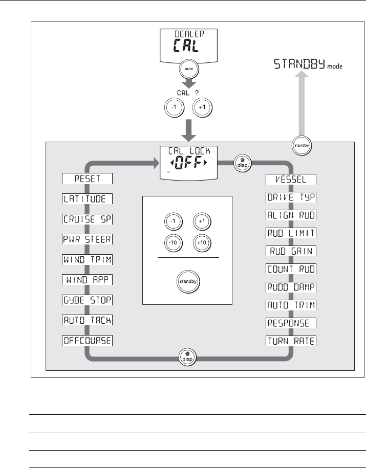
2.4 Dealer calibration
For information on how to access Dealer calibration, see Accessing the Calibration
modes, page 20.
Some Dealer calibration values are adjusted during the commissioning process (see
Chapter 1: Commissioning & setup), and once the SPX system has been
commissioned you should not normally need to change Dealer calibration values.
However if you decide you want to change values in Dealer calibration, be aware that
the Dealer calibration mode includes items that have a significant impact on SPX-5
Wheel system operation and can affect your boat’s safety.
Screen Text Options
WIND TRIM
Range = 1 to 9
1 to 3 - Least responsive to wind changes (less system activity)
4 to 6 - Moderate response to wind changes
7 to 9 - Most responsive to wind changes (more system activity)
Screen Text Options
RESPONSE
Range = 1 to 9
Level 1 to 3 minimizes the amount of pilot activity. This conserves
power, but may compromise short-term course-keeping accuracy.
Level 4 to 6 should give good course keeping with crisp, well con-
trolled turns under normal operating conditions
Level 7 to 9 gives the tightest course keeping and greatest rudder
activity (and power consumption). This can lead to a rough passage
in open waters as the SPX system may ‘fight’ the sea.
WARNING: Dealer calibration
Changing the Dealer calibration values can have a significant
affect on the SPX system steering characteristics and therefore
on the safety of your boat.
81307_2.book Page 25 Tuesday, July 24, 2012 8:34 AM
26 SmartPilot X-Series Commissioning & Setup Guide
Seatrial calibration lock
This screen controls the access to Seatrial calibration.
Vessel type
Selecting the correct vessel type, enables the SPX system to set appropriate values
for other calibration settings, to give optimum performance. Refer to the table on page
33 for default values.
Screen text Options
CAL LOCK OFF
Calibration lock off – Seatrial calibration can be accessed (default)
CAL LOCK ON
Calibration lock on – Seatrial calibration cannot be accessed
Accessing
Dealer Calibration
Dealer Calibration
D10603-1
To exit & save changes
2 seconds
2 seconds
(saves changes)
+
or
or
To adjust values
81307_2.book Page 26 Tuesday, July 24, 2012 8:34 AM
Chapter 2: SPX system settings 27
Drive type
The drive type setting controls how the SPX system drives the steering system.
Align rudder
The align rudder screen is displayed only if the rudder reference option is fitted.
If the rudder reference option is fitted, use this screen is used to calibrate the rudder
bar display. This should be set when commissioning the SPX system (see page 34).
Options
DISPLACE
Power-driven boats which do not plane
(Typically below 15 kts top speed)
SEMI DISPLACE
Faster power-driven boats which do not plane
(Typically 15-20 kts top speed)
PLANING
Planing boats with inboard engine(s) and shaft drives
(NOT boats with outdrives)
STERN DRV
Boats with outdrives or outboard engines
WORK BOAT
Commercial tugs, fishing vessels, etc
SAIL BOAT
Sailing boat
Drive Drive Type Setting
Drive Type 3
Linear
Rotary
Typically found on yachts
I/O (stern)
Found on Powerboats
Drive Type 4
Hydraulic reversing pump
Used on yachts and powerboats with hydraulic
steering
Drive Type 5
Constant running hydraulic pumps. Controlled by
solenoid valves
Found on light commercial and larger boats
D6404-1
D6405-1
D6406-1
81307_2.book Page 27 Tuesday, July 24, 2012 8:34 AM

28 SmartPilot X-Series Commissioning & Setup Guide
Rudder limit
The rudder limit screen is displayed only if the rudder reference option is fitted.
If the rudder reference option is fitted, this screen is used to set the limits of the rudder
control just inside the mechanical end stops, and thus avoid putting the steering
system under unnecessary load. This should be set when commissioning the SPX
system (see page 8).
Rudder gain
Rudder gain is a measure of how much helm the SPX system applies to correct
course errors. The higher the setting the more rudder will be applied.
The rudder gain setting is set automatically as part of the AutoLearn process
(see page 12).
.
Counter rudder
Counter rudder is the amount of rudder the SPX system applies to try to prevent the
boat from yawing off course. Higher counter rudder settings result in more rudder
being applied.
The default counter rudder gain is set as part of the initial seatrial AutoLearn process
(see page 12).
Rudder damping
If the SPX system ‘hunts’ when trying to position the rudder, adjust the rudder
damping value to minimize this. Increasing the rudder damping value reduces
hunting. Increase the damping one level at a time until the autopilot stops hunting, and
always use the lowest acceptable value.
Screen Text Range
ALIGN RUD
-9° to +9° in 1° steps
Screen Text Range
RUD LIMIT
10° to 40° in 1° steps
Screen Text Range
RUDD GAIN
1 to 9
Screen Text Range
COUNT RUD
1 to 9 (Do NOT set to 0)
Screen Text Range
RUDD DAMP
1 to 9
81307_2.book Page 28 Tuesday, July 24, 2012 8:34 AM

Chapter 2: SPX system settings 29
AutoTrim
The AutoTrim setting determines the rate at which the SPX system applies ‘standing
helm’ to correct for trim changes caused by varying wind loads on the sails or
superstructure.
The default AutoTrim is set as part of the AutoLearn process (see page 12).
If you need to change the setting, increase the AutoTrim one level at a time and use
the lowest acceptable value:
• If the SPX system gives unstable course keeping or excessive drive activity with a
change in the heel angle, decrease the AutoTrim level.
• If the SPX system reacts slowly to a heading change due to a change in the heel
angle, increase the AutoTrim level.
• If the AutoTrim level is too high, the boat will be less stable and snake around the
desired course.
Response level
This sets the default SPX system response level setting. The response level controls
the relationship between course keeping accuracy and the amount of helm/drive
activity. You can make temporary changes to response during normal operation (see
your Pilot Controller Operating Guide for details).
Turn rate limit
This limits your boat’s rate of turn under SPX system control.
Setting Effect
AUTO TRIM OFF
No trim correction
AUTO TRIM 1
to
4
Auto trim applied:
1 = Slowest, 4 = Fastest
Screen Text Options
RESPONSE
Range = 1 to 9
Level 1 to 3 minimizes the amount of pilot activity. This conserves
power, but may compromise short-term course-keeping accuracy
Level 4 to 6 should give good course keeping with crisp, well con-
trolled turns under normal operating conditions
Level 7 to 9 gives the tightest course keeping and greatest rudder
activity (and power consumption). This can lead to a rough passage
in open waters as the SPX system may ‘fight’ the sea.
Screen Text Range
TURN RATE
1° to 30° per second in 1° steps
81307_2.book Page 29 Tuesday, July 24, 2012 8:34 AM
30 SmartPilot X-Series Commissioning & Setup Guide
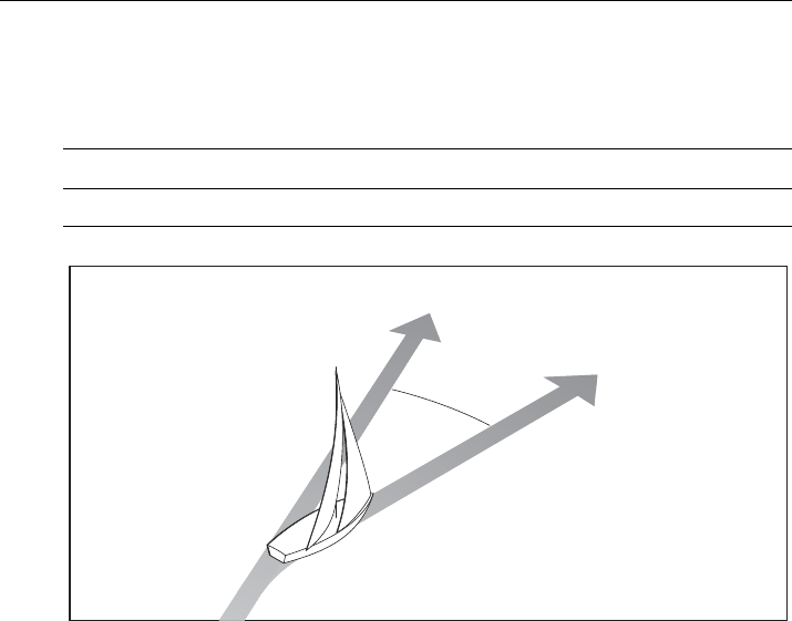
Off course angle
This screen determines the angle used by the
OFF COURSE
alarm (see your
Operating Guide). The
OFF COURSE
alarm operates if the pilot strays off course by
more than the specified angle for more than 20 seconds.
AutoTack
The AutoTack angle is the angle through which the boat will turn when you select an
automatic tack (see page 24).
Gybe inhibit
With gybe inhibit on:
• You will be able to perform an AutoTack into the wind
• To prevent accidental gybes, the SmartPilot will prevent the boat from performing
an AutoTack away from the wind
With gybe inhibit off, you can perform an AutoTack into or away from the wind.
See page 24.
Wind selection
Note: Only available if appropriate wind data is available.
This screen determines whether the boat steers to apparent or true wind in Wind Vane
mode. See page 24.
WindTrim
WindTrim controls how quickly the SPX system responds to changes in the wind
direction. Higher wind trim settings will result in a system that is more responsive to
wind changes. See page 25.
Screen Text Range
OFF COURSE
15° to 40° in 1° steps
Locked heading
Boat heading
15˚ minimum
D10648-1
81307_2.book Page 30 Tuesday, July 24, 2012 8:34 AM

Chapter 2: SPX system settings 31
PowerSteer
If you have a joystick connected to your SPX system, use this screen to select the
required joystick mode of operation. For detailed operating information, refer to the
guide supplied with the joystick
.
Cruise speed
Set the cruise speed to the boat’s typical cruising speed. If neither the speed through
the water nor the speed over ground are available via SeaTalk or NMEA, the SPX
system will use the cruise speed value you set here as a default when calculating
course changes.
Latitude
If valid latitude data is available via SeaTalk or NMEA, the SPX system will use this
data instead of the calibration value.
System reset
CAUTION: Losing settings at system reset
Do NOT carry out a System RESET unless advised to do so by a
Raymarine dealer. If you complete a reset you will lose the SPX
system calibration settings. You will then need to repeat the SPX
system commissioning process.
Carrying out a System reset will reset User calibration, Seatrial calibration and Dealer
calibration settings to their default values.
Note: the Display calibration settings will not change, as these are stored in each individual con-
troller
Options
OFF
Joystick off
1
1 = Proportional power steer
Proportional power steer applies rudder in proportion to joystick movement – the
further the joystick is held over, the greater the applied rudder.
2
2 = Bang-bang power steer
Bang-bang power steer applies continuous rudder in the direction of the lever
movement – to improve control, the speed of rudder movement changes with the
angle of the lever. For maximum speed, push the lever hardover. If you return the
lever to the center position, the rudder will remain in its current position.
Screen Text Range
CRUISE SP
4 to 60 knots
Screen Text Range
LATITUDE
0° to 80° in 1° steps
81307_2.book Page 31 Tuesday, July 24, 2012 8:34 AM

32 SmartPilot X-Series Commissioning & Setup Guide
To carry out a system reset:
1. Select the System reset (
RESET
) screen in Dealer calibration.
2. Press
+1
then press
auto
.
3. The screen will then show an
ARE YOU SURE
message. Either:
• Press
auto
to cancel the reset
or
•Press
+1
again to select YES and reset the SPX system.
4. You will then see the
CAL LOCK
screen:
• Hold down
standby
for 2 seconds to save the new settings, then turn the SPX
system computer power off and back on.
If you reset the system parameters, you must carry out the SPX system
commissioning process before using the SPX system again.
81307_2.book Page 32 Tuesday, July 24, 2012 8:34 AM

Chapter 2: SPX system settings 33
2.5 System defaults
Vessel type
Factory
Default
Displacement
Semi-
Displacement
Planing
Stern Drive (I/O)
Work Boat
Sail Boat
Calibration Lock OFF OFF OFF OFF OFF OFF OFF
Vessel Type 0 DISPLACE SEMI
DISPLACE
PLANING STERN
DRV
WORK
BOAT
SAIL BOAT
Drive Type: S1
S2/S3
3
3
4
4
4
4
4
4
3
3
4
5
3
3
Rudder Alignment00 0000 0
Rudder Limit 30 30 30 20 20 30 30
Rudder Gain 45 4445 2
Counter Rudder 4 3 5 5 5 2 2
Rudder Damping 2 2 2 2 2 3 2
AutoTrim 22 3332 1
Response: Gyro
Non-G
5
2
5
2
5
2
5
2
5
5
5
2
5
2
Turn Rate Limit 5 5 5 5 5 5 5
Off Course Angle20202020202020
Power Steer
(Joystick)
OFF
AutoRelease: S1
S2/S3
OFF
OFF
OFF
ON
AutoTack Angle 100 100
Gybe Inhibit ON ON
Wind Type APP APP
Wind Trim 5 5
Cruise Speed 8 8 8 8 20 8 8
Latitude 0 0 0 0 0 0 0
Variation 00 0000 0
Autopilot Reset OFF OFF OFF OFF OFF OFF OFF
81307_2.book Page 33 Tuesday, July 24, 2012 8:34 AM

34 SmartPilot X-Series Commissioning & Setup Guide
81307_2.book Page 34 Tuesday, July 24, 2012 8:34 AM

35
SmartPilot X-Series Specifications
SPX SmartPilot computer specifications
Nominal supply voltage
X-10
X-30
X-SOLENOID
X-CAN
12 or 24 V DC (fuse protected at 15A)
12 or 24 V DC (fuse protected at 40A)
12 or 24 V DC (fuse protected at 15A)
12 or 24 V DC (fuse protected at 10A)
Operating voltage range 10 V to 32 V DC
Power consumption (standby)
X-10
X-30
X-SOLENOID
X-CAN
300 mA
300 mA
300 mA
???
Gyro internal GyroPlus fitted onto circuit board as standard
Environmental conditions
operating temperature
non-operating temperature
relative humidity limit
water protection
-10°C to 55°C (14°F to 131°F)
-20°C to 70°C (-4°F to 158°F)
80%
drip resistant when mounted vertically
Storage conditions when
packed
temperature range
relative humidity limit
-5°C to 50°C (23°F to 122°F)
75%
Dimensions (width, height, depth)
307mm (12.1 in), 195 mm (7.7 in), 70 mm (2.8 in)
Weight
X-10
X 30, X-SOLENOID
X-CAN
1.1 kg (2.42 lbs)
2.2 kg (4.85 lbs)
???
Inputs Fluxgate compass, rudder position sensor, NMEA 0183 v2.3,
SeaTalk, SeaTalkng, power, sleep switch
Outputs
X-10, X -0
X-SOLENOID
X-CAN
NMEA 0183 v2.3, SeaTalk, SeaTalkng, drive motor, drive clutch
NMEA 0183 v2.3, SeaTalk, SeaTalkng, bypass valve, solenoid drive
NMEA 0183 v2.3, SeaTalk, SeaTalkng, IPS drive, jet drive
Steering drive compatibility
X 10
X 30
X-SOLENOID
X-CAN
All Type 1 drives/pumps (excluding CR pumps) (drive voltage must
match boat’s supply voltage)
All Type 1, Type 2 and Type 3 drives / pumps (drive voltage must
match boat’s supply voltage)
CR pumps etc.
Volvo Penta IPS system, Rolls Royce Kamewa water jet drive.
Drive motor output
X-10
X-30
continuous 10A at supply voltage
continuous 30A at supply voltage
81307_2.book Page 35 Tuesday, July 24, 2012 8:34 AM

36 SmartPilot X-Series Commissioning & Setup Guide
Drive clutch output
X-10
X-30
X-SOLENOID
1.2A at 12 / 24 V selectable
3.0A at 12 / 24 V selectable
2.0A at 12 / 24 V selectable
SeaTalk output
X-10
X-30, X-SOLENOID
X-CAN
2A at 12 V (fuse protected at 2A)
3A at 12 V (fuse protected at 3A)
???
SeaTalkng output
X-10
X-30, X-SOLENOID
X-CAN
2A at 12 V (fuse protected at 2A)
3A at 12 V (fuse protected at 3A)
???
NMEA 0183 v2.3 inputs/out-
puts
See relevant installation guide for received/transmitted NMEA 0183.
Fast heading output
X-10, X-30, X-SOLENOID
X-CAN
NMEA 0183 - 5 Hz
SeaTalkng - 10 Hz
NMEA 2000 - 10 Hz
Fuses
Power Terminals
SeaTalk Terminals
Standard automotive blade fuses
X-10: 15A. X-30: 40A. X-SOLENOID: 15A. X-CAN: ???
X-10: 2A. X-30 and X-SOLENOID: 3A. X-CAN: ???
EMC compliance: Europe 2004/108/EC (EMC)
Australia and New Zealand: C-Tick, Compliance Level 2
SPX SmartPilot computer specifications
81307_2.book Page 36 Tuesday, July 24, 2012 8:34 AM

Glossary 37
Glossary
Term Meaning
AST
(Advanced Steer-
ing Technology)
AST (Advanced Steering Technology) is Raymarine’s unique advanced
steering algorithm. It uses inputs from a wide variety of sensors to tune the
autopilot’s operation to provide superior control of the boat in any condi-
tion.
AutoLearn Self-learning calibration feature available on Raymarine course comput-
ers.
AWG American Wire Gauge
CE Marked on products that comply with defined European Community stan-
dards
CR pump Constant Running hydraulic pump
EMC
(Electromagnetic
Compatibility)
When powered up, all electrical equipment produces electromagnetic
fields. These can cause adjacent pieces of electrical equipment to interact
with one another, and this can degrade their performance. By following
the EMC guidelines in this handbook, you can minimize these effects by
ensuring optimum Electromagnetic Compatibility (EMC) between equip-
ment.
Fluxgate Standard Raymarine compass supplied with core pack
GPS Global Positioning System
GyroPlus Raymarine’s GyroPlus yaw sensor that measures the boat’s rate of turn. It
is built into the course computer.
Hz Hertz (cycles per second)
I/O drive Inboard/Outboard or stern drive
MARPA Mini Automatic Radar Plotting Aid
NMEA The NMEA (National Maritime Electronics Association) protocol is an
internationally accepted serial communication interface standard for
sharing data between electronic equipment. Raymarine products can
share information with non-SeaTalk equipment using the NMEA 0183
protocol.
SeaTalk SeaTalk is Raymarine’s proprietary communication system. It links prod-
ucts to provide a single, integrated system sharing power and data.
SeaTalk bus This refers to the continuous SeaTalk system connecting together a
series of Raymarine units.
Yaw Boat’s rate of turn (°/sec)
81307_2.book Page 37 Tuesday, July 24, 2012 8:34 AM

38 SmartPilot X-Series Commissioning & Setup Guide
81307_2.book Page 38 Tuesday, July 24, 2012 8:34 AM

39
Contents
A
Accessing calibration modes, 20
Applicability, 1
AutoLearn, 12
AutoTack, 24
selecting Relative Tack, 24
setting angle, 24
AutoTack angle, 30
AutoTrim, 17, 29
C
Calibration modes, 19
Checking system operation, 14
Commissioning
Dockside, 2
align rudder indicator, 7
checking connections, 3
checking pilot operating sense, 4
set drive type, 7
set vessel type, 6
switching on, 3
requirement, 2
Seatrial, 8
AutoLearn, 12
conditions, 8
heading alignment, 10
swinging the compass, 9
Counter rudder, 16, 28
D
Data pages
available functions, 22
setup, 21
Dealer Calibration
Gybe inhibit, 30
Dealer calibration, 5
align rudder indicator, 27
AutoTack angle, 30
AutoTrim, 29
counter rudder, 28
cruise speed, 31
drive type, 27
latitude, 31
off course warning angle, 30
power steer, 31
response level, 29
rudder damping, 28
rudder gain, 28
rudder limit, 28
seatrial calibration lock, 26
system reset, 31
turn rate limit, 29
vessel type, 26
wind type, 30
WindTrim, 30
Default settings, 33
Display calibration, 21
data page setup, 21
heading selection, 21
Dockside procedures, 2
Drive type, 27
setup, 7
G
Glossary, 37
Gybe inhibit, 24
H
Heading alignment, 10
Heading selection, 21
J
Joystick setup, 31
L
Latitude, 31
M
Magnetic/true heading selection, 21
Manual setup
AutoTrim, 17
checking operation, 14
counter rudder, 16
response level, 15
O
Off course warning angle, 30
P
Power steer (joystick) mode, 31
Product disposal, iii
R
Relative Tack, 24
Resetting the system, 31
Response level, 25, 29
temporary changes, 15
Rudder damping, 28
Rudder gain, 28
setup, 15
Rudder indicator alignment, 27
setup, 7
81307_2.book Page 39 Tuesday, July 24, 2012 8:34 AM

40 SmartPilot X-Series Commissioning & Setup Guide
Rudder limits, 28
S
Safety
electrical, i
general, i
navigation, i
Seatrial Calibration, 8
AutoLearn, 12
conditions, 8
heading alignment, 10
swinging the compass, 9
Seatrial calibration lock, 26
Settings
Gybe inhibit, 30
Setup
accessing calibration modes
, 20
AutoTack, 24
AutoTack angle, 30
AutoTrim, 17, 29
counter rudder, 16, 28
cruise speed, 31
data pages, 21
drive type, 7, 27
for joystick operation, 31
gybe inhibit, 24
heading selection, 21
latitude, 31
off course warning angle, 30
power steer (joystick) mode, 31
response level, 25, 29
rudder damping, 28
rudder gain, 15, 28
rudder indicator alignment, 7, 27
rudder limit, 28
seatrial calibration lock, 26
turn rate limit, 29
vessel type, 6, 26
wind type, 24, 30
WindTrim, 25, 30
Swinging the compass, 9
Switching on, 3
System defaults, 33
System reset, 31
T
Turn rate limit, 29
U
User calibration, 23
gybe inhibit, 24
response level, 25
wind type, 24
WindTrim, 25
V
Vessel type, 26
setup, 6
W
Wind type, 24, 30
WindTrim, 25, 30
81307_2.book Page 40 Tuesday, July 24, 2012 8:34 AM
