A83004_2 Ray Marine St4000+ Service Manual
RayMarine_ST_4000_Service_Manual
autopilot + ST4000+ st4000
User Manual: Pdf
Open the PDF directly: View PDF ![]() .
.
Page Count: 34

ST4000+ Autopilots
ST4000+ Autopilots Service Manual 83115-1
Warning
CE Marking of Equipment/Replacement Parts
If the Autohelm equipment under repair, test, calibration, installation or setting to work carries the European CE mark,
only parts and components supplied or approved for such use by Raytheon should be used in order to maintain
compliance with the relevant CE requirements.
Incorporation, use or attachment, by any means, of parts or components not supplied for or not approved for such use by
Raytheon or, if supplied or approved for use by Raytheon, not properly fitted in accordance with instructions published,
provided or recommended by Raytheon, may cause the equipment to malfunction and, in particular, to become unsafe or
to no longer meet the relevant CE requirements. In these circumstances, Raytheon Marine Europe Ltd excludes liability
to the fullest extent permissible in law for any loss or damage including any liability for its contribution to such loss or
damage by its negligent acts or omissions .
ST4000+ Autopilots Service Manual
For use on
Z326, Wheel Autopilot
Z327, Tiller Autopilot
Z332, Tiller GP Autopilot
D3730-1

ST4000+ Autopilots
ST4000+ Autopilots Service Manual 83115-1

Contents
ST4000+ Autopilots Service Manual 83115-1
Contents
Chapter 1. ST4000+ Control Head ......................................................................................... 1
1.1 PCB Changes ................................................................................................. 1
1.2 Disassembly/Assembly.................................................................................... 2
ST4000+ Control Head spare parts list ........................................................... 3
1.3 PCB Details .................................................................................................... 4
Input/Output Signals (refer to Figure 2. Circuit Diagram) ................................... 4
Circuit Diagram..................................................................................... 5
PCB Layout .................................................................................................. 6
PCB Component list ............................................................................. 7
Chapter 2. Fluxgate Compass Transducer ............................................................................ 9
2.1 Functional test ................................................................................................. 9
2.2 Magnetic deviation .......................................................................................... 9
2.3 Disassembly/assembly ................................................................................... 10
Fluxgate Compass spare parts list................................................................ 10
Chapter 3. Wheel Drive Actuator ......................................................................................... 11
3.1 Wheel Drive Actuator test................................................................................ 11
3.2 Disassembly/assembly ................................................................................... 12
Wheel Drive Actuator spare parts list ............................................................ 13
Disassembly ............................................................................................... 14
Belt removal ....................................................................................... 14
Pinion sprocket removal ...................................................................... 14
Drive lever and eccentric removal......................................................... 14
Motor removal .................................................................................... 14
Gearbox removal ................................................................................ 15
Gearbox disassembly ................................................................. 15
Assembly ................................................................................................... 16
Gearbox assembly.............................................................................. 16
Motor assembly .................................................................................. 16
Adjustment eccentric assembly ........................................................... 16
Drive lever and eccentric assembly ...................................................... 17
Pinion sprocket and belt assembly ....................................................... 17
Drive ring closure ................................................................................ 17
3.3 Setting Belt Tension ........................................................................................ 18
Tools required: ............................................................................................ 18
Motor drive box ........................................................................................... 18
Motor drive box parts .......................................................................... 19
Procedure ................................................................................................. 19

ST4000+ Autopilots
ST4000+ Autopilots Service Manual 83115-1
Chapter 4. Tiller Drive Actuator ............................................................................................ 21
4.1 Tiller Drive Actuator test .................................................................................. 21
4.2 Disassembly/assembly ................................................................................... 22
Tiller Drive Actuator spare parts list ............................................................... 23
Tiller Drive Actuator GP conversion kit (W003) ............................................... 23
Chapter 5. Tiller Drive Actuator GP ...................................................................................... 25
5.1 Tiller Drive Actuator GP test ............................................................................ 25
5.2 Disassembly/assembly ................................................................................... 26
Tiller Drive Actuator GP spare parts list ......................................................... 27

Chapter 1. ST4000+ Control Head
ST4000+ Autopilots Service Manual 83115-1 1
Chapter 1. ST4000+ Control Head
1.1 PCB Changes
When a PCB is changed, it may be necessary to set the new PCB to the
required pilot type, ST4000+ Wheel, ST4000+ Tiller or ST4000+ Tiller GP
1. If the instrument is disassembled, fit the reflector, diffuser, elastomers,
LCD and surround to the PCB
2. Apply 12V power to the instrument/PCB assembly
3. Press and hold STDBY for 14 seconds until CAL ? is displayed
4. Momentarily press +1 and -1 together to gain access to extended
calibration (dealer set - up)
5. Advance from the CAL LOCK page to the pilot type page by pressing
DISP
6. Use the +1 and -1 buttons to set the pilot type as required, 4000 WHL
(wheel) or 4000 TILL (tiller)
7. Press STDBY to exit extended calibration
8. Switch off the power supply. Do not disconnect
9. When the pilot is fully powered down, switch the power on again
10.Check that the required pilot type is momentarily displayed before
STANDBY is entered. If not, repeat the set - up procedure. In the case of
a second failure, change the PCB.

ST4000+ Autopilots
2 ST4000+ Autopilots Service Manual 83115-1
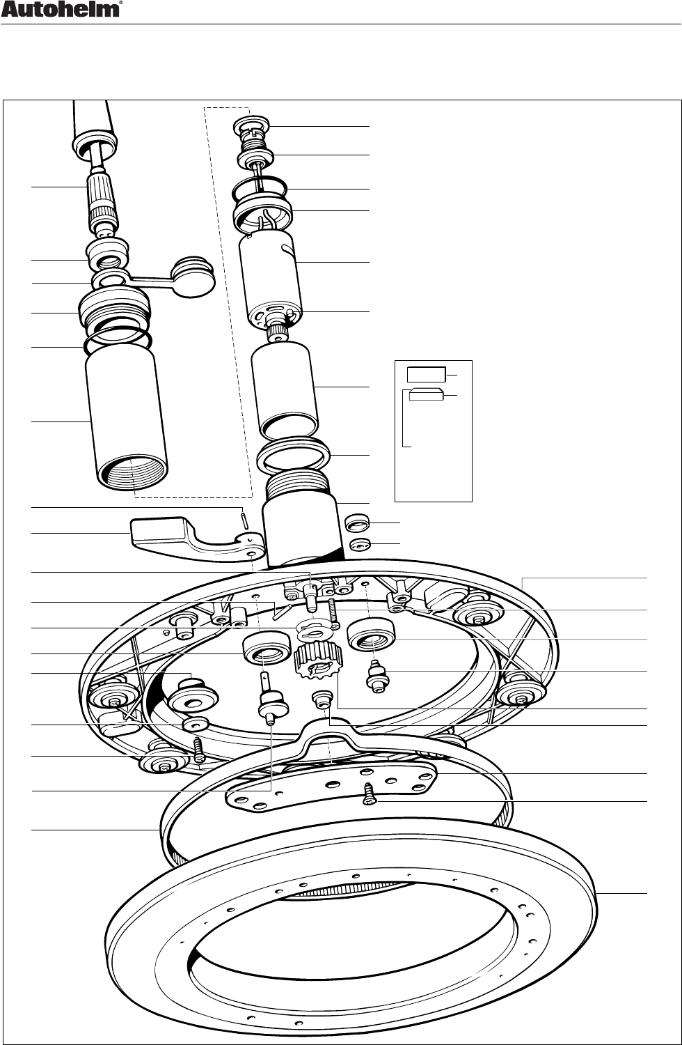
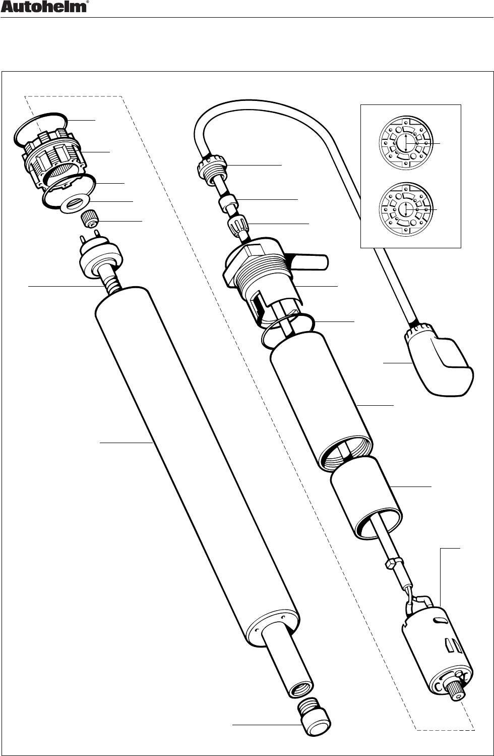
1.2 Disassembly/Assembly
1. Facia
2. Keypad
3. Label
4. Window insert
5. LCD surround
6. LCD
7. Elastomer strip (x2)
8. Diffuser
9. Reflector
D3721-1
2 17 (Note A)
1345
6 7 (x2) 8 (Note B) 9 10 12 (Note C)
11 (x3) 14 13 11 (x8)
10. PCB
11. Retaining screw (x11)
12. Case seal
13. Rear cover
14. Buzzer connector
15. Label
16. Bulkhead gasket
17. Keypad shim (earlier units only)
Notes:
A. Earlier production units have a shim (17) fitted
to aid keypad compression.
B. The castellated top edge of the diffuser (8) fits
under the legs of the LEDs on the top edge of
the PCB (10).
C. It is recommended that a new case seal (12) is
fitted on assembly.
15
16
Figure 1: ST4000+ Control Head exploded view

Chapter 1. ST4000+ Control Head
ST4000+ Autopilots Service Manual 83115-1 3
ST4000+ Control Head spare parts list
The item numbers refer to Figure 1: ST4000+ Control Head exploded view
Item Spare Description Part No. Comments
1 Facia W115
2 Keypad Q219
Display kit,
including
Q220
3 Label (selection) Fit ST4000+ label
4 Window insert
5 LCD surround
6 LCD
7 Elastomer (x2)
Diffuser kit,
including
W117
8 Diffuser
9 Reflector
10 PCB Q221 ST4000+/ST5000+ PCB
Fixing kit,
including
W120
11 Screw (x11)
12 Case seal W118
Back cover assembly,
including
W119
13 Back cover
Comes fitted with,
Gortex filter,
Sleeving,
Buzzer and
14 Buzzer connecter
15 Label (selection) Fit ST4000+ label
16 Bulkhead gasket W125
Sun cover D340 Not illustrated

ST4000+ Autopilots
4 ST4000+ Autopilots Service Manual 83115-1
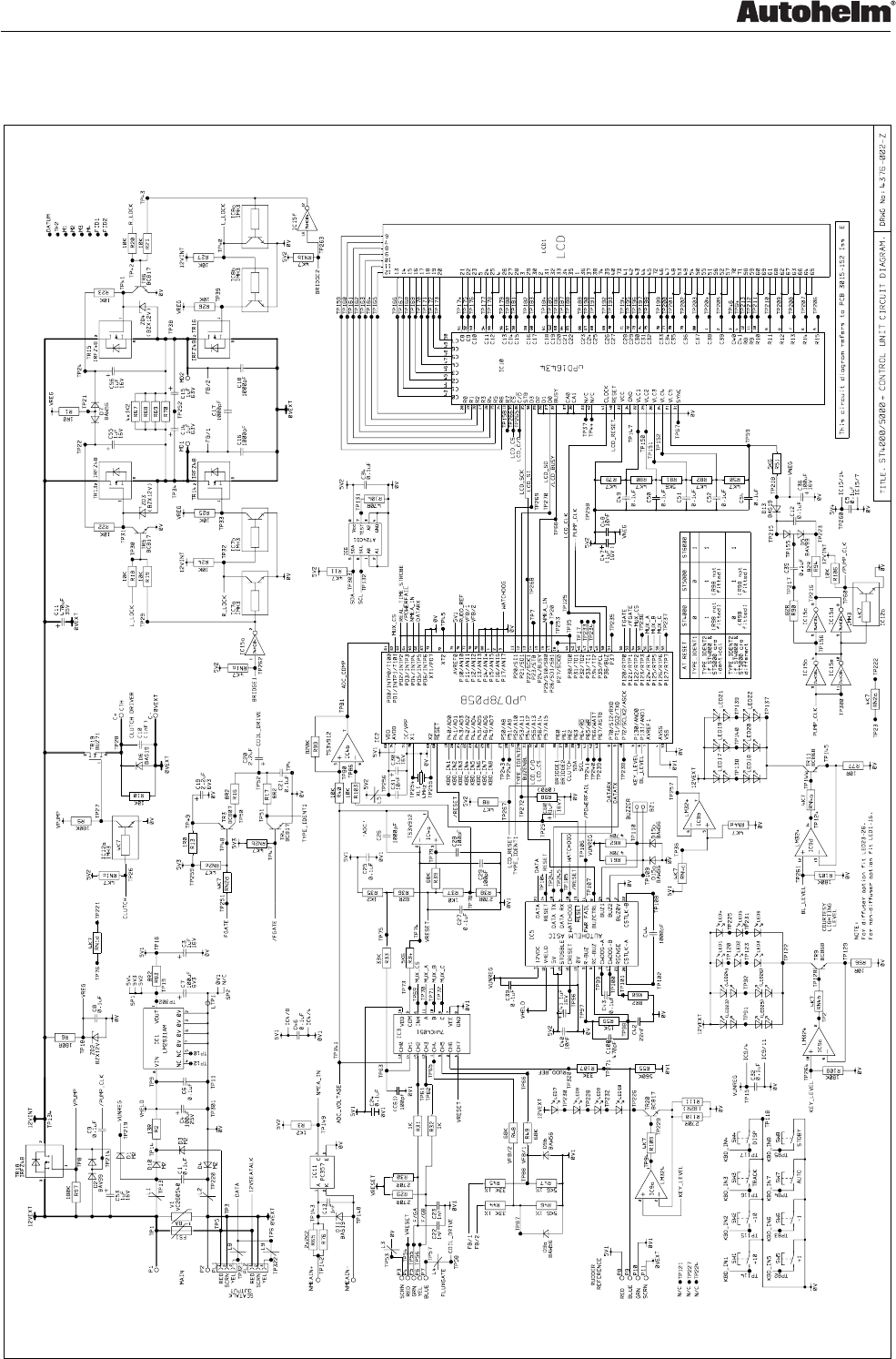
1.3 PCB Details
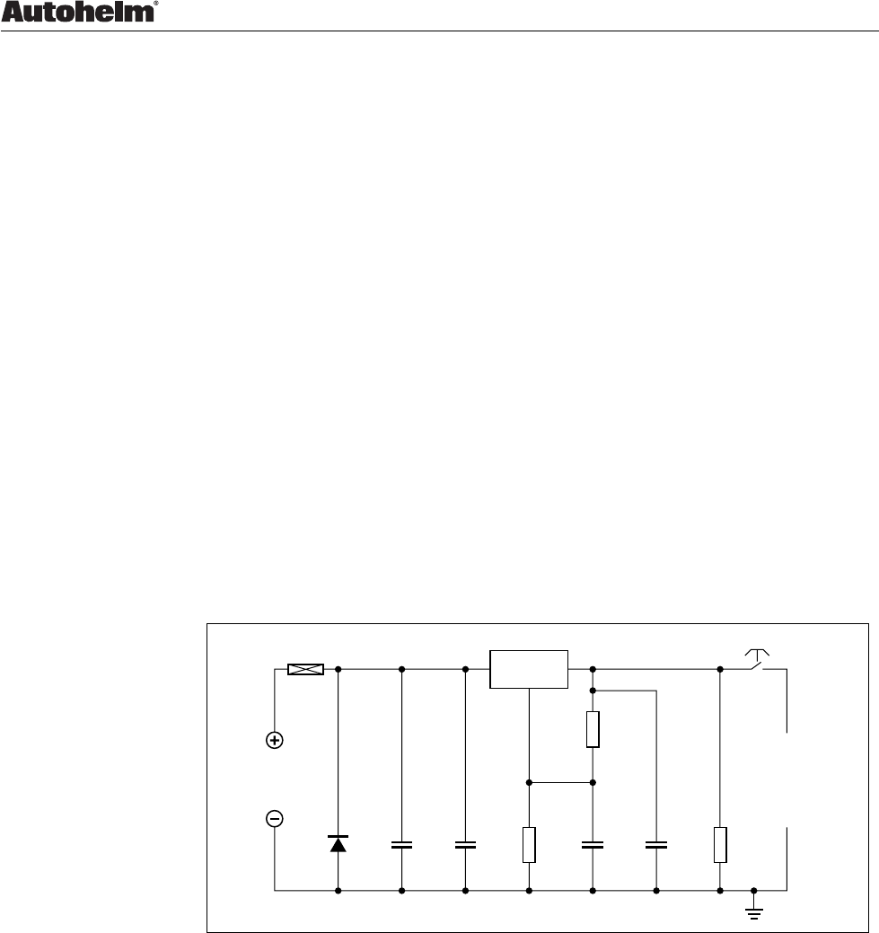
Input/Output Signals (refer to Figure 2. Circuit Diagram)
Pin No. Signal Description
PL1/1 +12V Nominal 12V dc
PL1/2 0V in 0V
PL1/3 SeaTalk Intermittent streams of (nominal) 12V pulses
PL2/1 +12V Nominal 12V dc
PL2/2 0V in 0V
PL2/3 SeaTalk Intermittent streams of (nominal) 12V pulses
P1 +12V Nominal 12V dc
P2 0V in 0V
P3 SCRN 0V
P4 Bias Nominal 2.5V dc (VRESET)
P5 F/GA +2.5V dc
P6 F/GB +2.5V dc
P7 Coil drive AC signal, 17 cycles at 7.9kHz, driven twice
every 1/16 second
P8 Rudder reference Nominal 5V supply to rudder reference
supply
P9 Rudder reference 0 to 5V dc (nominal) rudder reference output
P10 Rudder reference 0V 0V
P11 SCRN 0V
C+ Clutch +12V if Autopilot engaged; otherwise 0V
C– Clutch 0V 0V
MD1 MD1 When Autopilot engaged and depending on
direction of drive, intermittent variable length
pulses, nominal 12V; otherwise 0V
MD2 MD2 When Autopilot engaged and depending on
direction of drive, intermittent variable length
pulses, nominal 12V; otherwise 0V
NMEA in+ NMEA+ Intermittent streams of (nominal) 12V pulses
NMEA in– NMEA– 0V
Chapter 1. ST4000+ Control Head
ST4000+ Autopilots Service Manual 83115-1 5
Circuit Diagram
D3723-1
Figure 2: Circuit Diagram

ST4000+ Autopilots
6 ST4000+ Autopilots Service Manual 83115-1
PCB Layout
D3722-1
Taken from Drawing No: 4376-001 Issue: P Date: 03.10.97
Figure 3: PCB Component Layout
Chapter 1. ST4000+ Control Head
ST4000+ Autopilots Service Manual 83115-1 7
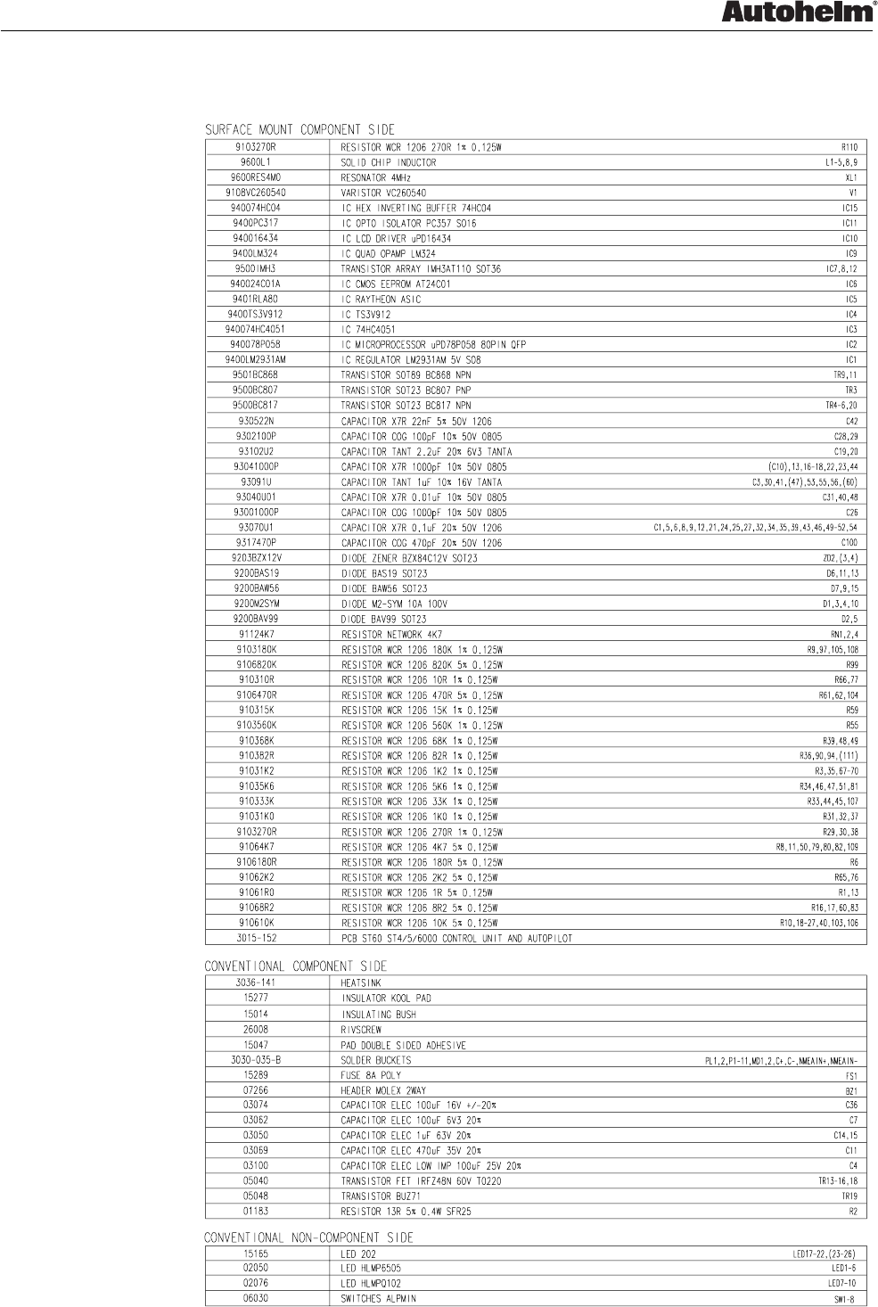
PCB Component list
D3724-1
Taken from Drawing No: 4376-001 Issue: P Date: 03.10.97

ST4000+ Autopilots
8 ST4000+ Autopilots Service Manual 83115-1

Chapter 2. Fluxgate Compass Transducer
ST4000+ Autopilots Service Manual 83115-1 9
Chapter 2. Fluxgate Compass Transducer
2.1 Functional test
Disconnect the Fluxgate from the Autopilot and check continuity as follows:
Cable colour Connector pin number Resistance
Screen to blue 2/4 < 10 ohms
Red to green 3/5 < 5 ohms
Red to yellow 3/6 < 5 ohms
Red to screen 3/2 Open circuit
2.2 Magnetic deviation
The Fluxgate Compass requires careful siting if optimum Autopilot
performance is to be acheived. The SeaTalk electronics is able to correct the
compass for most deviating magnetic fields present when the linearisation
procedure is carried out. Any further deviation, introduced after linearisation,
will introduce an error between the Fluxgate and the ship’s compass. This
can be removed by carrying out the linearisation again. If the displayed
deviation is greater than +/– 15 degrees the Fluxgate should be resited.
Note: The linearisation procedure should always be carried out if the
Fluxgate has been exchanged, removed or moved from its original mounting
position.

ST4000+ Autopilots
10 ST4000+ Autopilots Service Manual 83115-1
2.3 Disassembly/assembly
D3726-1
1274
365
8
9
1. Cover
2. Seal
3. Pivot retaining screw (x2)
4. Bracket
5. Pivot sub-assembly
6. Fluxgate sub-assembly
7. Body
8. Body screw (x4)
9. Cable
Figure 4. Fluxgate Compass exploded view
Fluxgate Compass spare parts list
The item numbers refer to Figure 4: Fluxgate Compass exploded view
Item Spare Description Part No. Comments
Compass base kit,
including
M096
3 Pivot retaining screw (x2)
4 Bracket
Fluxgate sub-assembly,
including
M022
5 Pivot sub-assembly (x2)
6 Fluxgate sub-assembly

Chapter 3. Wheel Drive Actuator
ST4000+ Autopilots Service Manual 83115-1 11
Chapter 3. Wheel Drive Actuator
3.1 Wheel Drive Actuator test
Carry out the passive and active tests detailed in Figure 6.
D2386-1
PSU
12V 15A
Switch
Fuse/CB
12A
Figure 5. Wheel Drive Actuator test connections
Change damaged
components
Check gears,
belt, rollers,
belt tension,
eccentric, drive
lever, motor
Start
No
Yes
Visually inspect unit
Rotate drive ring by hand
with clutch disengaged
No
Yes
OK
OK
Check resistance across
motor connector pins 2 and 3
is approximately 1 to 2 ohms
Change/adjust
as necessary
No
Yes
Check wiring
and connector
OK
Check motor
Change as
necessary
OK
D2390-1
No
Yes
Connect power supply
as in Figure 5
OK No
Yes
Change/adjust
as necessary
Switch on.Check drive ring
moves in opposite direction
to that of first test and
current is less than 2A
No
Yes
OK
Actuator OK.
End of test
Switch on, and with clutch
engaged, check drive ring
moves and current is less
than 2A
Restrain drive ring rotation
until 6.5A is obtained. Check
that belt does not slip.
OK No
Yes
Reverse polarity of supply
Restrain drive ring rotation
until 6.5A is obtained. Check
that belt does not slip.
No
Yes
OK
Check gears, belt,
rollers, belt
tension, eccentric,
drive lever, motor
Change/adjust
as necessary
Check gears, belt,
rollers, belt
tension, eccentric,
drive lever, motor
Figure 6. Wheel Drive Actuator test flowchart
ST4000+ Autopilots
12 ST4000+ Autopilots Service Manual 83115-1
3.2 Disassembly/assembly
98
D3727-1
10
18
17
16
11
521
1. Drive ring
2. Back mounting plate
assembly
3. Screw (x5)
4. Support plate
5. Belt
6. Bearing
7. Pinion sprocket
8. Roll pin
9. Drive lever
10. Drive wheel assembly
11. Drive eccentric assembly
12. Adjustment eccentric assembly
1 3(x5) 4 6 7 12 13 22(x4) 2
14 15
14 15
Large chamfer of
adjustment locking
nut to face
protective cap
23 24 25 26 28 29 30 3127
20(x2) 19 32 33 34 35 36
13. Adjustment wheel assembly
14. Adjustment locking nut
15. Protection cap
16. Roller screw (x7)
17. Washer (x7)
18. Roller (x7)
19. Pin
20. Shim (x2)
21. Gearbox drive shaft/
gear carrier 'C'
22. Gearbox retaining screw (x4)
23. Gearbox
24. Red motor seal
25. Flux ring
26. Motor location peg
27. Motor
28. Motor clamp
29. Motor clamp 'O' ring
30. Connector
31. Connector seal
32. Sleeve
33. End cap 'O' ring
34. End cap
35. Sealing cap
36. Connector nut
37. Cable assembly
37
Figure 7. Wheel Drive Actuator exploded view

Chapter 3. Wheel Drive Actuator
ST4000+ Autopilots Service Manual 83115-1 13
Wheel Drive Actuator spare parts list
The item numbers refer to Figure 7: Wheel Drive A ctuator exploded view
Item Spare Description Part No. Comments
1 Drive ring N031
2 Back mounting plate assembly N013
Comes fitted with,
pre-assembled
gearbox, item 23
5 Belt D169
Pinion kit,
including
N014
7 Pinion sprocket
15 Protection cap
19 Pin
20 Shim (x2)
Drive lever kit,
including
N011
8 Roll pin
9 Drive lever
11 Drive eccentric assembly N024
Gearbox drive shaft/gear N026
carrier ‘C’ kit,
including
21 Gearbox drive shaft/
gear carrier ‘C’ See Figure 8, item 3
– Planet gear (x12) See Figure 8, item 4
– Shim See Figure 8, item 2
– ‘O’ ring See Figure 8, item 1
27 Motor N012
Wiring kit,
including
Q106
28 Motor clamp
29 Motor clamp ‘O’ ring
30 Connector
31 Connector seal
33 End cap ‘O’ ring
34 End cap
35 Sealing cap
36 Connector nut
37 Cable assembly

ST4000+ Autopilots
14 ST4000+ Autopilots Service Manual 83115-1
Disassembly
Belt removal
Refer to Figure 7. Wheel Drive Actuator exploded view.
1. Insert a wide flat, non-metalic blade into the gap between the drive ring
(1) and the back mounting plate (2). Gently lever the blade to force the
drive ring (1) off the rollers (18) of the back mounting plate (2). Repeat
this action in three to four places around the drive ring (1) in order to
remove.
2. Unscrew and remove the five screws (3). Detach the support plate (4)
from the back mounting plate (2).
3. Remove the belt (5).
Pinion sprocket removal
Refer to Figure 7. Wheel Drive Actuator exploded view.
1. Perform actions as described in
Belt removal
.
2. Lift the pinion sprocket (7) off the gearbox drive shaft/gear carrier ‘C’ (21).
Drive lever and eccentric removal
Refer to Figure 7. Wheel drive actuator exploded view.
1. Perform actions as described in
Pinion sprocket removal
.
2. Place a block with a suitable clearance hole under the drive lever/shaft
(9) to provide support and prevent the shaft bending when the roll pin is
driven out.
3. Drive out the roll pin (8).
4. Pull the drive lever (9) off the drive eccentric shaft (11).
5. Lift the drive eccentric assembly (11) and drive wheel assembly (10) off
the back mounting plate (2).
Motor removal
Refer to Figure 7. Wheel Drive Actuator exploded view.
1. Unscrew and remove the connector nut (36).
2. Remove the sealing cap (35).
3. Grip the gearbox (23), unscrew and remove the sleeve (32) ensuring the
connector does not rotate.
4. Withdraw motor (27)/location peg (26) disengaging it from the gearbox
(23). Slide off the flux ring (25).
Note: Although given separate item numbers, the gearbox (23) is an
integral part of the back mounting plate assembly (2) and the location
peg (26) is part of the motor (27).
Chapter 3. Wheel Drive Actuator
ST4000+ Autopilots Service Manual 83115-1 15
5. Desolder connector wires from the motor tags.
Gearbox removal
Refer to Figure 7. Wheel Drive Actuator exploded view.
1. Perform actions as described in
Pinion sprocket removal
,
and 1, 2, 3 and 4 in
Motor removal
.
2. Unscrew and remove the four gearbox retaining screws (22).
3. Separate the gearbox ( 23) from the back mounting plate assembly (2)
leaving the gearbox drive shaft/gear carrier ‘C’ (21) in place.
4. Support the gearbox drive shaft/gear carrier ‘C’ (21) and drive out the pin(19).
5 Withdraw the gearbox drive shaft/gear carrier ‘C’ (21) from the back
mounting plate assembly (2).
Gearbox disassembly
5
4
7
5
4
7
5
5
5
4
6
5
4
5
3
1
4
2
1. 'O' ring
2. Small shim spacer
3. Drive shaft/carrier assembly 'C'
4. Planet gear (x22)
5. Large shim spacer (x7)
6. Carrier assembly 'B'
7. Carrier assembly 'A' (x2)
8. Gear housing
8
D3725-1
Figure 8. Gearbox exploded view

ST4000+ Autopilots
16 ST4000+ Autopilots Service Manual 83115-1
Assembly
In all cases, assembly is a straight reversal of the steps described in
Disassembly
.
Gearbox assembly
Refer to Figure 7. Wheel Drive Actuator exploded view.
1. Rebuild gearbox. Refer to Figure 8. Gearbox exploded view
2. Fix the gearbox (23) to the back mounting plate assembly (2) using the
four gearbox retaining screws (22).
3. Slide the two shims (20) over the gearbox drive shaft/gear carrier ‘C’ (21)
and hard up against the back mounting plate assembly (2).
4. Support the gearbox drive shaft/gear carrier ‘C’ (21) and refit the pin (19).
Note: If the original pin (19) is bent or damaged a replacement pin can be
obtained from pinion kit, part no. N014.
Motor assembly
Refer to Figure 7. Wheel Drive Actuator exploded view.
1. Fit the red motor seal (24) over the threaded end of the gearbox (23).
2. Insert the connector wires through the motor clamp (28), and solder the
connector wires to the motor tags – red lead to the tag with a red spot,
black lead to the other motor tag.
3. Slide flux ring (25) on the motor (27) and fit onto the gearbox (23)
ensuring that the motor drive gear is fully engaged with the gear train and
the motor location peg (26) is engaged correctly into the gearbox (23).
4. Fit the ‘O’ ring (29) onto the motor clamp (28).
5. Place the connector seal (31) over the connector (30).
6. Screw the sleeve (32) with fitted ‘O’ ring (33) and end cap (34) onto the
gearbox (23).
7. Place the sealing cap (35) over the connector (36) and secure with the
connector nut (37).
Adjustment eccentric assembly
Refer to Figure 7. Wheel Drive Actuator exploded view.
1. Assemble the adjustment wheel assembly (13), adjustment eccentric
assembly (12), adjustment lock nut (14) with its chamfered edge facing
outwards, and protection cap (15) to the back mounting plate assembly (2).
Note: Ensure that the drive lever (9) is in the slack (declutched) position
and the adjustment eccentric assembly (12) is in its lowest position, so
that the belt (5) is at its slackest.

Chapter 3. Wheel Drive Actuator
ST4000+ Autopilots Service Manual 83115-1 17
Drive lever and eccentric assembly
Refer to Figure 7. Wheel Drive Actuator exploded view.
1. Assemble the drive eccentric assembly (11) and drive wheel assembly
(10) to the back mounting plate assembly (2).
2. Slide the drive lever (9) onto the drive eccentric assembly (11). Support
the drive lever (9) and insert the roll pin (8).
Note: Always use a new roll pin (8) on refit.
Pinion sprocket and belt assembly
Refer to Figure 7. Wheel Drive Actuator exploded view.
1. Slot the pinion sprocket (7) over the gearbox drive shaft (21) and pin (19).
2. With the drive lever (9) in its slack (declutched) position and the
adjustment eccentric assembly (12) is in its lowest position fit the belt (5)
around the pinion sprocket (7), drive wheel assembly (10) and
adjustment wheel assembly (13).
3. Position the support plate (4) with fitted bearing (6) onto the gearbox
drive shaft (21), drive eccentric assembly (11), adjustment eccentric
assembly (12) and over the screw pillars. Insert the five screws (3) and
secure the support plate (4).
Note: Take care not to cut new threads in the screw pillars when securing
the support plate (4).
Drive ring closure
Refer to Figure 7. Wheel Drive Actuator exploded view.
1. Rest the drive ring (1) over the rollers (18).
2. Locate the rollers (18) nearest the gearbox (23) into the groove of the
drive ring (1). Push down and around the drive ring (1) to progressively
snap the drive ring (1) over the remaining rollers (18).
3. Spin the drive ring (1) in both directions, two or three times, too ensure
the assembly is fully seated and free running.
ST4000+ Autopilots
18 ST4000+ Autopilots Service Manual 83115-1
3.3 Setting Belt Tension
The purpose of the belt tensioning procedure is to ensure that:
1. The belt is sufficiently tight to transmit the normal maximum drive
torques.
2. The belt is not over-tightened, as this will increase the backdrive load to a
level where it can be felt on the vessel’s wheel.
Tools required:
4000 Drive unit torque fixture
Service tool number - T033
4000 Drive unit torque adjuster
Service tool number - T032
Motor drive box and ammeter
Motor drive box
FS1
12V
BATTERY
Red (ZO78)
Brown (Z077)
Blue
ACTUATOR
15A
IC1
LM396K
D1
SW1
R1
121R
+
MR752
C1 +
4700uF
C2
4.7uF
R2 +
845R
C3 +
22uF
C4
4.7uF
R3
1KO
D2384-1
Figure 9. Motor drive box circuit diagram

Chapter 3. Wheel Drive Actuator
ST4000+ Autopilots Service Manual 83115-1 19
Motor drive box parts
Component Description
R1 Resistor 121R 0.1% metal film
R2 Resistor 845R 0.1% metal film
R3 Resistor 1k0 0.5W
C1 Capacitor 4700uF 20% electrolytic 25V
C2 Capacitor 4.7uF 10% solid tantalum 35V
C3 Capacitor 22uF 10% solid tantalum 35V
C4 Capacitor 4.7uF 10% solid tantalum 35V
D1 Diode MR 752
IC1 LM396K High power 10A regulator
F1 Fuse 15A quick blow
Fuseholder 1.1/4 inch
SW1 Switch Single pole single throw
TO3 Insulating kit
Diecast box
Procedure
1. Screw the drive ring clamp to the front ring. Use the group of two holes on
their own, not two holes in a group of four. Screw the torque restraint pin
into the back mounting plate
2. Connect the motor to the motor drive box, using an in - line ammeter (0 -
10 amps) to measure current
3. Connect the motor drive box to a 12V battery. The drive box provides a
regulated 10.5V supply to the motor
4. Engage the drive unit clutch
5. Use the eccentric adjuster to loosen (anti - clockwise) the locking nut and
allow the eccentric to move to the minimum tension position
6. Switch on the drive to the motor and, using a 1.5mm Allen key, rotate the
eccentric anticlockwise (as viewed from above) to increase belt tension
until the belt just stops slipping (motor stalled)
7. Check that the motor current is approximately 6.5 amps
8. Tighten the locking nut, apply Loctite to retain the setting and switch off
the motor drive.

ST4000+ Autopilots
20 ST4000+ Autopilots Service Manual 83115-1

Chapter 4. Tiller Drive Actuator
ST4000+ Autopilots Service Manual 83115-1 21
Chapter 4. Tiller Drive Actuator
4.1 Tiller Drive Actuator test
Carry out the passive and active tests detailed in Figure 11. Tiller Drive Actuator
test flowchart.
D2394-1
Fuse/CB
12A
1
23
Blue Brown
Actuator deck plug
PSU
12V 15A
Switch
Blue
Brown
Figure 10. Tiller Drive Actuator test connections
Change damaged
components
Check gears,
thrust rod,
actuator body,
motor
Start
No
Yes
Visually inspect unit
Extend and retract
thrust arm by hand
No
Yes
OK
OK
Check resistance across
motor connector pins 2 and 3
is approximately 1 to 2 ohms
Change
as necessary
No
Yes
Check wiring
and connector
OK
Check motor
Change as
necessary
OK
Switch on,
check thrust rod moves and
current less than 2.5A
Connect power supply
as in Figure 10.
OK No
Yes
Change
as necessary
Switch on.
Check thrust rod moves
in opposite direction
to that of first test and
current less than 2.5A
No
Yes
OK
Actuator OK.
End of test
D3728-1
No
Yes
Check gears,
thrust rod,
actuator body,
motor
Check gears,
thrust rod,
actuator body,
motor
Change
as necessary
Switch off.
Reverse connections to PSU
Figure 11. Tiller Drive Actuator test flowchart
ST4000+ Autopilots
22 ST4000+ Autopilots Service Manual 83115-1
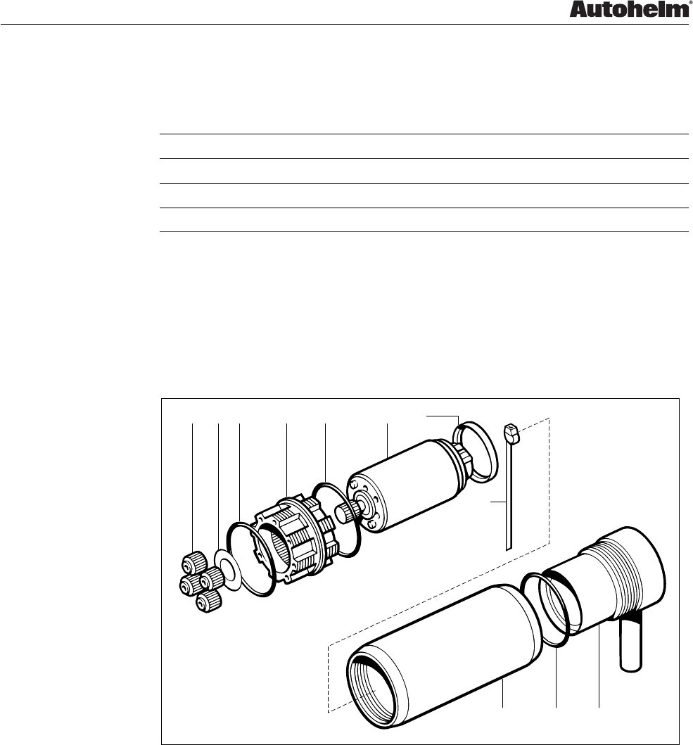
4.2 Disassembly/assembly
D2395-1
1. Ram cap
2. Thrust tube
3. Lead screw assembly
4. Planet gear (x4)
5. Shim
6. 'O' ring (x3)
7. Gear annulus
8. Motor (Q114)
9. Flux ring
10. Motor sleeve
11. End cap assembly
12. Cable clamp
13. Clamp seal
14. Cable clamp nut
15. SeaTalk deck plug
1
Notes:
A. Ensure cable clamp nut (14) is unscrewed before
undoing the motor sleeve.
B. The hole in the gear annulus (7) that accepts the
drive gear of the motor (8) is of a different diameter
to that of the ST4000+ GP gear annulus.
C. Care should be taken not to cross-thread the
annulus (7) when screwing into the thrust tube (2).
3
4 (x4) 56
7
Notes B & C
6
8
9
6
10
11
12
13
14
Note A
15
2
ST4000+ GP
16mm diameter
End view of Annulus (7)
ST4000+
13mm diameter
Figure 12. Tiller Drive Actuator exploded view
Chapter 4. Tiller Drive Actuator
ST4000+ Autopilots Service Manual 83115-1 23
Tiller Drive Actuator spare parts list
The item numbers refer to Figure 12: Tiller Drive Actuator exploded view
Item Spare Description Part No. Comments
Drive module Q047 Complete drive unit
8 Motor Q114
11 End cap assembly W014
Tiller Drive Actuator GP conversion kit (W003)
This GP conversion kit (W003) gives the option of converting the ST4000+
which has the power to helm boats of up to 6,500 kg (14,300 lbs)
displacement, to the ST4000+ GP which would push the limit up to 9,000 kg
(20,000 lbs) displacement.
8
1. Planet gear (x4)
2. Shim
3. 'O' ring (x3)
4. Gear annulus
5. Motor
6. Motor spacer
7. Cable tie
8. Motor sleeve
9. End cap assembly
D2397-1
1 2 3 4 3 56
7
3 9
Figure 13. Tiller Drive Actuator GP conversion kit (W003)

ST4000+ Autopilots
24 ST4000+ Autopilots Service Manual 83115-1

Chapter 5. Tiller Drive Actuator GP
ST4000+ Autopilots Service Manual 83115-1 25
Chapter 5. Tiller Drive Actuator GP
5.1 Tiller Drive Actuator GP test
Carry out the passive and active tests detailed in Figure 15. Tiller Drive Actuator
GP test flowchart.
D2398-1
Fuse/CB
12A
1
23
Blue Brown
Actuator deck plug
PSU
12V 15A
Switch
Blue
Brown
Figure 14. Tiller Drive Actuator GP test connections
Change damaged
components
Check gears,
thrust rod,
actuator body,
motor
Start
No
Yes
Visually inspect unit
Extend and retract
thrust arm by hand
No
Yes
OK
OK
Check resistance across
motor connector pins 2 and 3
is approximately 1 to 2 ohms
Change
as necessary
No
Yes
Check wiring
and connector
OK
Check motor
Change as
necessary
OK
Switch on,
check thrust rod moves and
current less than 2A
Connect power supply
as in Figure 10.
OK No
Yes
Change
as necessary
Switch on.
Check thrust rod moves
in opposite direction
to that of first test and
current less than 2A
No
Yes
OK
Actuator OK.
End of test
D3731-1
No
Yes
Check gears,
thrust rod,
actuator body,
motor
Check gears,
thrust rod,
actuator body,
motor
Change
as necessary
Switch off.
Reverse connections to PSU
Figure 15. Tiller Drive Actuator GP test flowchart

ST4000+ Autopilots
26 ST4000+ Autopilots Service Manual 83115-1
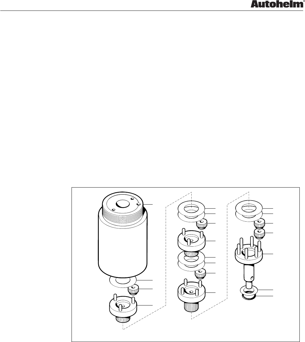
5.2 Disassembly/assembly
1
2
3
4 (x4) 56
6
8
10
6
11
12
13
14
16
1. Ram cap
2. Thrust tube
3. Lead screw assembly
4. Planet gear (x4)
5. Shim
6. 'O' ring (x3)
7. Gear annulus
8. Motor
9. Cable tie
10. Motor spacer
11. Motor sleeve
12. End cap assembly
13. Cable clamp
14. Clamp seal
15. Cable clamp nut
16. SeaTalk deck plug
D2396-1
15
Note A
7
Notes B & C
Notes:
A. Ensure cable clamp nut (15) is unscrewed before
undoing the motor sleeve.
B. The hole in the gear annulus (7) that accepts the
drive gear of the motor (8) is of a different diameter
to that of the ST4000+ gear annulus.
C. Care should be taken not to cross-thread the
annulus (7) when screwing into the thrust tube (2).
ST4000+ GP
16mm diameter
End view of Annulus (7)
ST4000+
13mm diameter
9
Figure 16. Tiller Drive Actuator GP exploded view

Chapter 5. Tiller Drive Actuator GP
ST4000+ Autopilots Service Manual 83115-1 27
Tiller Drive Actuator GP spare parts list
The item numbers refer to Figure 16: Tiller drive actuator GP exploded view
Item Spare Description Part No. Comments
Drive module Q086 Complete drive unit
ST4000+ GP kit,
incuding
W003 Serves as an upgrade
4 Planet gear (x4) conversion kit for the
5 Shim ST4000+ tiller drive
6 ‘O’ ring (x3) actuator.
7 Annulus
8 Motor
9 Cable tie
10 Motor spacer
11 Motor sleeve
12 End cap assembly

ST4000+ Autopilots
28 ST4000+ Autopilots Service Manual 83115-1

ST4000+ Autopilots
ST4000+ Autopilots Service Manual 83115-1

ST4000+ Autopilots
ST4000+ Autopilots Service Manual 83115-1
Raytheon Marine Company
676 Island Pond Road
Manchester
New Hampshire 03109-5420
Tel: (001 603) 647 7530
Fax: (001 603) 634 4756
Raytheon Marine Europe Limited
Anchorage Park, Portsmouth
Hampshire PO3 5TD
Tel: (01705) 693611
Fax: (01705) 694642
http: //www.raytheon.com
