SPU2 Overview Manual
User Manual: Pdf
Open the PDF directly: View PDF ![]() .
.
Page Count: 80
- SPU2 OVERVIEW
- About This Manual
- Changes Since Release of 5th Edition
- Overview of SPU2
- Sound Generation
- Register List
- Classification of Registers
- Registers in Pairs
- VOLL / VOLR : Voice volume
- PITCH : Pitch when sound is generated
- ADSR1 / ADSR2 : Envelope
- ENVX : Current value of envelope
- VOLXL / VOLXR : Current value of volume
- PMON0 / PMON1 : Pitch modulation specification
- NON0 / NON1 : Voice allocation to noise generator
- VMIX* : Mixing specification of voice output
- MMIX : Output specification after voice mixing
- IRQAH / IRQAL : Interrupt address specification
- KON0 / KON1 : Key-on specification
- KOF0 / KOF1 : Key-off specification
- TSAH / TSAL : Transfer start address
- SSAH / SSAL : Starting address of waveform data
- LSAXH / LSAXL : Address of loop point
- NAXH / NAXL : Address of waveform data to be read next
- ESAH / ESAL : Starting address in the work area for effect processing
- EEAH : End address in the work area for effect processing
- ENDX0 / ENDX1 : Endpoint passing flag
- MVOLL / MVOLR : Master volume
- EVOLL / EVOLR : Return volume of effect
- AVOLL / AVOLR : Volume for external input
- BVOLL / BVOLR : Volume for sound data input
- MVOLXL / MVOLXR : Current value of master volume
- Appendix

SPU2 Overview
Copyright © 2002 Sony Computer Entertainment Inc.
All Rights Reserved.
SCE Confidential

SCE CONFIDENTIAL SPU2 Overview Version 6.0
© SCEI
-2-
© 2002 Sony Computer Entertainment Inc.
Publication date: April 2002
Sony Computer Entertainment Inc.
1-1, Akasaka 7-chome, Minato-ku
Tokyo 107-0052 Japan
Sony Computer Entertainment America
919 East Hillsdale Blvd.
Foster City, CA 94404, U.S.A.
Sony Computer Entertainment Europe
30 Golden Square
London W1F 9LD, U.K.
The SPU2 Overview is supplied pursuant to and subject to the terms of the Sony Computer Entertainment
PlayStation® license agreements.
The SPU2 Overview is intended for distribution to and use by only Sony Computer Entertainment licensed
Developers and Publishers in accordance with the PlayStation® license agreements.
Unauthorized reproduction, distribution, lending, rental or disclosure to any third party, in whole or in part, of
this book is expressly prohibited by law and by the terms of the Sony Computer Entertainment PlayStation®
license agreements.
Ownership of the physical property of the book is retained by and reserved by Sony Computer Entertainment.
Alteration to or deletion, in whole or in part, of the book, its presentation, or its contents is prohibited.
The information in the SPU2 Overview is subject to change without notice. The content of this book is
Confidential Information of Sony Computer Entertainment.
® and PlayStation® are registered trademarks, and GRAPHICS SYNTHESIZERTM and
EMOTION ENGINETM are trademarks of Sony Computer Entertainment Inc. All other trademarks are property
of their respective owners and/or their licensors.

SCE CONFIDENTIAL SPU2 Overview Version 6.0
© SCEI
-3-
About This Manual
The "SPU2 Overview" describes the functions, configuration, and sound generation mechanisms of the SPU2,
the sound processor for the PlayStation 2.
- Chapter 1 "Overview of SPU2" describes the configuration and main functions of the SPU2 and the format
of waveform data used as a sound source.
- Chapter 2 "Sound Generation" describes voice generation using waveform data as a sound source, sound
data stream input/output, mixing, and effects.
- Chapter 3 "Register List" describes the registers that control the SPU2.
- Chapter 4 "Appendix" shows the volume variation rates for values of the envelope rate parameters.
Changes Since Release of 5th Edition
Since release of the 5th Edition of the SPU2 Overview Manual, the following changes have been made.
Note that each of these changes is indicated by a revision bar in the margin of the affected page.
Ch. 2: Sound Generation
• Section 2.2.6. Monaural Output, has been added on page 29.
• A correction has been made to the description following Figure 2-12 Sound Data Output on page 31.
Ch. 4: Appendix
• A correction has been made to the “Time” heading in the Exponential Decrement Mode table on page
76.
• A correction has been made to the “0.1110” row in the Linear Decrement Mode table on page 78.

SCE CONFIDENTIAL SPU2 Overview Version 6.0
© SCEI
-4-
(This page is left blank intentionally)

SCE CONFIDENTIAL SPU2 Overview Version 6.0
© SCEI
-5-
Glossary
Term Definition
EE Emotion Engine. CPU of the PlayStation 2.
EE Core Generalized computation and control unit of EE. Core of the CPU.
COP0 EE Core system control coprocessor.
COP1 EE Core floating-point operation coprocessor. Also referred to as FPU.
COP2 Vector operation unit coupled as a coprocessor of EE Core. VPU0.
GS Graphics Synthesizer.
Graphics processor connected to EE.
GIF EE Interface unit to GS.
IOP Processor connected to EE for controlling input/output devices.
SBUS Bus connecting EE to IOP.
VPU (VPU0/VPU1) Vector operation unit.
EE contains 2 VPUs: VPU0 and VPU1.
VU (VU0/VU1) VPU core operation unit.
VIF (VIF0/VIF1) VPU data decompression unit.
VIFcode Instruction code for VIF.
SPR Quick-access data memory built into EE Core (Scratchpad memory).
IPU EE Image processor unit.
word Unit of data length: 32 bits
qword Unit of data length: 128 bits
Slice Physical unit of DMA transfer: 8 qwords or less
Packet Data to be handled as a logical unit for transfer processing.
Transfer list A group of packets transferred in serial DMA transfer processing.
Tag Additional data indicating data size and other attributes of packets.
DMAtag Tag positioned first in DMA packet to indicate address/size of data and address
of the following packet.
GS primitive Data to indicate image elements such as point and triangle.
Context A set of drawing information (e.g. texture, distant fog color, and dither matrix)
applied to two or more primitives uniformly. Also referred to as the drawing
environment.
GIFtag Additional data to indicate attributes of GS primitives.
Display list A group of GS primitives to indicate batches of images.

SCE CONFIDENTIAL SPU2 Overview Version 6.0
© SCEI
-6-
(This page is left blank intentionally)

SCE CONFIDENTIAL SPU2 Overview Version 6.0
© SCEI
-7-
Contents
1. Overview of SPU2................................................................................................................................................................... 9
1.1. Features of SPU2 ........................................................................................................................................................... 10
1.1.1. Core.......................................................................................................................................................................... 10
1.1.2. Sound Data Input Function.................................................................................................................................. 10
1.1.3. Voice Processing Function ................................................................................................................................... 10
1.1.4. Sound Data Output Function............................................................................................................................... 11
1.1.5. Digital Effect Processing....................................................................................................................................... 11
1.1.6. Local Memory......................................................................................................................................................... 11
1.1.7. External Output...................................................................................................................................................... 12
1.2. Local Memory ................................................................................................................................................................ 13
1.2.1. Data Allocated in Local Memory ......................................................................................................................... 13
1.2.2. Addressing in Local Memory................................................................................................................................ 14
1.2.3. Interrupt by Access................................................................................................................................................ 14
1.3. Waveform Data Format................................................................................................................................................ 15
1.3.1. Waveform Data Block........................................................................................................................................... 15
1.3.2. Endpoint.................................................................................................................................................................. 15
1.3.3. Loop Processing ..................................................................................................................................................... 16
1.4. Reset ................................................................................................................................................................................ 17
2. Sound Generation ................................................................................................................................................................. 19
2.1. Voice Processing............................................................................................................................................................ 20
2.1.1. Sound Sources......................................................................................................................................................... 20
2.1.2. Pitch Transformation............................................................................................................................................. 22
2.1.3. Pitch Modulation.................................................................................................................................................... 23
2.1.4. Envelope.................................................................................................................................................................. 24
2.1.5. Volume .................................................................................................................................................................... 25
2.1.6. Key-On/Key-Off................................................................................................................................................... 26
2.1.7. Mixing Switch ......................................................................................................................................................... 27
2.2. Sound Data Input Processing....................................................................................................................................... 28
2.2.1. Sound Data Input Area ......................................................................................................................................... 28
2.2.2. Volume Processing................................................................................................................................................. 28
2.2.3. Mixing with Voice Output .................................................................................................................................... 29
2.2.4. Bypass Processing (CORE0) ................................................................................................................................ 29
2.2.5. 32-bit Sound Data Input (CORE1) ..................................................................................................................... 29
2.2.6. Monaural Output.................................................................................................................................................... 29
2.3. Sound Data Output Processing ................................................................................................................................... 30
2.4. Mixing.............................................................................................................................................................................. 32
2.5. Digital Effect Processing .............................................................................................................................................. 33
2.5.1. Signal Flow for Digital Effect Processing........................................................................................................... 33
2.5.2. Work Area for Digital Effect Processing............................................................................................................ 33
2.5.3. Effect Volume ........................................................................................................................................................ 34

SCE CONFIDENTIAL SPU2 Overview Version 6.0
© SCEI
-8-
2.6. Master Volume ...............................................................................................................................................................35
2.7. Interrupt Processing.......................................................................................................................................................36
3. Register List ............................................................................................................................................................................39
3.1. Classification of Registers..............................................................................................................................................40
3.2. Registers in Pairs.............................................................................................................................................................41
VOLL / VOLR : Voice volume......................................................................................................................................42
PITCH : Pitch when sound is generated........................................................................................................................44
ADSR1 / ADSR2 : Envelope..........................................................................................................................................45
ENVX : Current value of envelope................................................................................................................................46
VOLXL / VOLXR : Current value of volume.............................................................................................................47
PMON0 / PMON1 : Pitch modulation specification..................................................................................................48
NON0 / NON1 : Voice allocation to noise generator................................................................................................49
VMIX* : Mixing specification of voice output .............................................................................................................50
MMIX : Output specification after voice mixing..........................................................................................................51
IRQAH / IRQAL : Interrupt address specification.....................................................................................................52
KON0 / KON1 : Key-on specification.........................................................................................................................53
KOF0 / KOF1 : Key-off specification..........................................................................................................................54
TSAH / TSAL : Transfer start address..........................................................................................................................55
SSAH / SSAL : Starting address of waveform data .....................................................................................................56
LSAXH / LSAXL : Address of loop point ...................................................................................................................57
NAXH / NAXL : Address of waveform data to be read next...................................................................................58
ESAH / ESAL : Starting address in the work area for effect processing .................................................................59
EEAH : End address in the work area for effect processing......................................................................................60
ENDX0 / ENDX1 : Endpoint passing flag .................................................................................................................61
MVOLL / MVOLR : Master volume ............................................................................................................................62
EVOLL / EVOLR : Return volume of effect..............................................................................................................64
AVOLL / AVOLR : Volume for external input ..........................................................................................................65
BVOLL / BVOLR : Volume for sound data input......................................................................................................66
MVOLXL / MVOLXR : Current value of master volume.........................................................................................67
4. Appendix.................................................................................................................................................................................69
4.1. Rate Parameter Table.....................................................................................................................................................70
4.1.1. +Lin Mode...............................................................................................................................................................71
4.1.2. –Lin Mode ...............................................................................................................................................................72
4.1.3. +Exp Mode (Normal phase).................................................................................................................................73
4.1.4. +Exp Mode (Reverse phase).................................................................................................................................74
4.1.5. –Exp Mode..............................................................................................................................................................75
4.1.6. Decay Rate (DR).....................................................................................................................................................76
4.1.7. Sustain Level (SL) ...................................................................................................................................................77
4.1.8. –Lin Mode for Release Rate (RR).........................................................................................................................78
4.1.9. –Exp Mode for Release Rate (RR) .......................................................................................................................79

SCE CONFIDENTIAL SPU2 Overview Version 6.0
© SCEI
-9-
1. Overview of SPU2
This chapter provides an overview of the SPU2.

SCE CONFIDENTIAL SPU2 Overview Version 6.0
© SCEI
-10-
1.1. Features of SPU2
The SPU2 is a sound synthesis processor, which is composed of two cores. The SPU2 also contains local
memory and external I/O.
The two cores have the ability to:
• Reproduce sound data input successively from the host.
• Process voices.
• Output voice-processed sound data to the host successively.
• Perform digital effect processing.
The following sections describe the SPU2 components and core functions.
1.1.1. Core
The cores (CORE0 and CORE1) are the basic components of the SPU2, each having a sound generation
function with 24 voices. They operate at a frequency of 36.864 MHz, and have a sound generation resolution of
48 kHz. The unit of processing, 1/48000 second, is represented as 1Ts.
When setting the same register successively (e.g. when varying the pitch of a sound consecutively to realize a
portamento), write operations to the register must be at least 1Ts apart. (Write operations to some registers
must be at least 2 Ts apart. For details, refer to the Description for each register in "3. Register List".) If the
register is written in less than the specified time interval (less than 1 Ts when not specified), the SPU2 operations
become indeterminate, and expected results cannot be obtained. This produces serious effects, particularly on
registers working as a switch, such as key-on or key-off.
CORE0 and CORE1 are functionally equal and operate independently. They are connected in such a way that
the output from CORE0 is input to CORE1 and the final mixed sound is output from CORE1.
1.1.2. Sound Data Input Function
The sound data input function processes 16-bit or 32-bit data strings transferred successively from the host to
the SPU2 as sound data, and outputs them by mixing with the voice-processed output. CORE0 and CORE1
each have one stereo input channel.
The input buffer is a reserved area in the local memory. To transfer data smoothly, it uses a double buffer
function, which requests a data transfer when half of the area is processed.
For details, refer to "2.2. Sound Data Input Processing".
1.1.3. Voice Processing Function
Sound in the SPU2 is generated in units of voices. Each core has 24 voices, so the whole SPU2 can generate 48
voices.
Each voice has waveform data compressed by ADPCM as a sound source. After pitch transformation, pitch
modulation and envelope processing, the outputs of each voice are mixed and become the final sound output.

SCE CONFIDENTIAL SPU2 Overview Version 6.0
© SCEI
-11-
Sound Source
The sound source is waveform data that has been compressed by ADPCM, and is decoded (decompressed)
by hardware at a sampling rate of 48 kHz. The noise generator of each core can be used as a sound source as
well.
Pitch Transformation
Sound can be generated by varying the pitch of the sound source within the range of -12 octaves to +2
octaves.
Pitch Modulation
The pitch of the sound source can be modulated by using the crest value of another voice.
Envelope Processing
The envelope, which controls volume variation from key-on to key-off, is specified with five parameters:
Attack Rate, Decay Rate, Sustain Rate, Sustain Level and Release Rate. For Attack Rate, Sustain Rate and
Release Rate, non-linear variation can be specified.
Voice Volume
Volume can be set for the L channel and R channel of each voice. Constant, linear and exponential variation
curves can be selected.
Mixing/Switching
24 voices/stereo output (48 channels in total) are synthesized into 2 stereo units in each core. Each voice
can be added to the output or not.
Refer to "2.1. Voice Processing" for details of voice processing.
1.1.4. Sound Data Output Function
Mixed sounds (2 stereo units per core) and a specified two-channel voice can be output to the host successively.
This allows the sound data generated by the SPU2 to be processed by the host processor.
An output buffer is reserved in the local memory. In order to transfer data smoothly, it uses a double buffer
function, which requests a data transfer when half of the area is processed.
Refer to “2.3. Sound Data Output Processing for details.
1.1.5. Digital Effect Processing
Digital effects such as reverb, echo and delay can be applied to the mixed sounds.
Although digital effects can be processed independently in each core, the effects in CORE1 can be reapplied to
the final output from CORE0.
The work area for digital effect processing is in the local memory.
Refer to "2.5. Digital Effect Processing" for details.
1.1.6. Local Memory
The SPU2 has 2 MBytes (16 Mbits) of local memory for its exclusive use. This memory is used as a buffer for
sound data I/O, a waveform data area for voice processing, and a work area for digital effect processing. The
remaining memory can be used freely.

SCE CONFIDENTIAL SPU2 Overview Version 6.0
© SCEI
-12-
It is possible to access the local memory from the host via DMA transfer or single transfer. Sound generation
never stops when transferring data, but it might not be correctly executed when overwriting waveform data
being used by the SPU2. To avoid this, an interrupt can be generated for the host when each core accesses a
specific address in the local memory.
Refer to "1.2. Local Memory" for details.
1.1.7. External Output
The SPU2 adopts the following functions as methods of outputting final sounds.
• Digital output through S/PDIF (Sony/Philips Digital Interface)
• Analog output through D/A converter
SCE CONFIDENTIAL SPU2 Overview Version 6.0
© SCEI
-13-
1.2. Local Memory
The local memory is memory for the SPU2’s exclusive use; it is used as a data I/O buffer with the host and as a
work area of the SPU2.
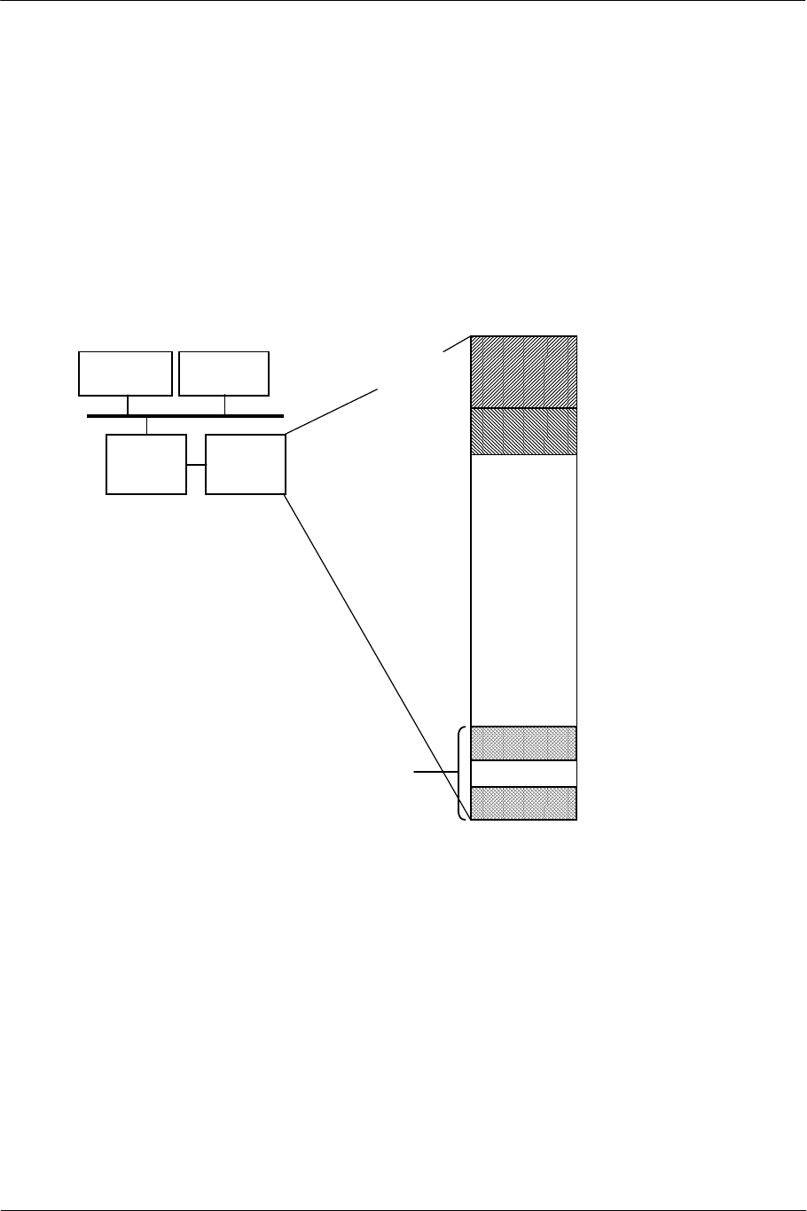
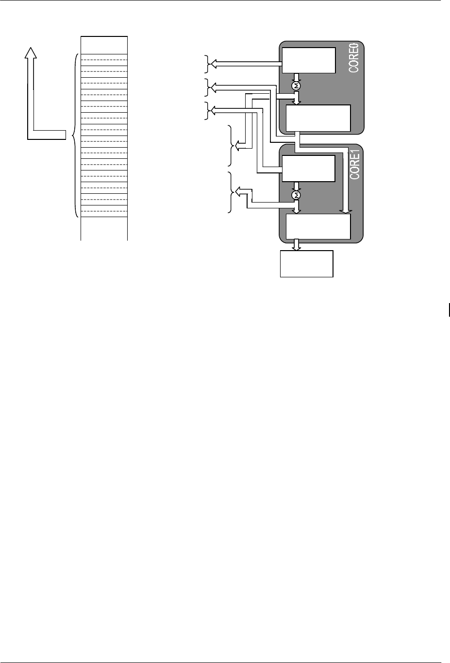
1.2.1. Data Allocated in Local Memory
The local memory is divided into the following four areas.
Host Host
Memory
SPU2 Local
Memory
Sound Data
Output Area
Sound Data
Input Area
00 0000
00 1FFF
00 2000
00 27FF
0X XXXX
0? FFFF
0
y
yyyy
0F FFFF
Waveform
Data Area
Work Area for
Digital Effect
Delay
Processing
(2 MB)
00 2800
A
ddress
(in short-word units)
Figure 1-1 Memory Allocation and Addressing in Local Memory
Sound Data Input Area
This is the sound data input buffer from the host; its address is fixed.
Sound data is successively written from the host, and the written data is sequentially read via hardware and
processed as sound data by the SPU2.
Sound Data Output Area
This is the sound data output buffer from the SPU2 to the host; its address is fixed.
Sound data generated in the SPU2 is written successively, and is readable from the host sequentially.
SCE CONFIDENTIAL SPU2 Overview Version 6.0
© SCEI
-14-
Digital Effect Work Areas
The work areas used by the cores for digital effect delay processing are in 2 locations. The start address of
each location can be set freely, but the end address has restrictions on alignment.
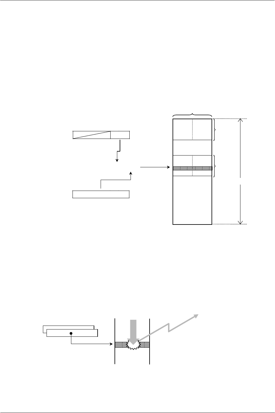
1.2.2. Addressing in Local Memory
The local memory is configured in 16-bit units; addresses are allocated every 16 bits (short word). Each address
is specified with a 32-bit value, of which 22 bits are enabled. The lower 20 bits of the 22 bits show a range of 2
Mbytes, and the upper 2 bits are set to 00.
Since the SPU2 registers are configured in 16-bit units, each register which performs addressing is a pair of high
and low registers.
Address H
Higher Address Register
00 0000
XX 0000
XX FFFF
0F FFFF
128 KB
128 KB
16 bits
2 MB
15 5 0
XX
15 0
YYYY
XX YYYY
Address L
Lower Address Register
Figure 1-2 Addressing
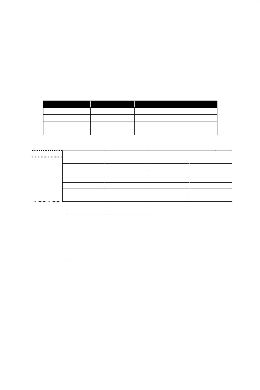
1.2.3. Interrupt by Access
When one of the cores accesses a specific address in the local memory, an interrupt can be generated for the
host. The address for generating an interrupt can be set, one per core, with the IRQAH and IRQAL registers.
Interrupts generated by both cores are detected at the same time on the host. A function provided by the sound
library represents which core has generated the interrupt.
Interrupt to Host
CORE0
[IRQAH/L]
Local Memory
Arbitrary
Processing
Figure 1-3 Interrupt by Process Access
(Example: Specification in CORE0)
For details, refer to "2.7. Interrupt Processing".
SCE CONFIDENTIAL SPU2 Overview Version 6.0
© SCEI
-15-
1.3. Waveform Data Format
The waveform data that becomes the sound source of each voice is in a format unique to the SPU2, by adopting
ADPCM as a compression method.
1.3.1. Waveform Data Block
Waveform data is configured in units of 16-byte blocks, each of which includes a 16-bit header and 28 4-bit
samples. The following attributes are included in the header.
Field Bit Position Contents
LOOP/START 10 Loop point information
LOOP 9 Loop existence/non-existence
LOOP/END 8 Endpoint information
DECODE 7:0 Parameter for decoding
15 11 7 3 0
Header Loop Flag Decode Parameter
SD3 SD2 SD1 SD0
SD7 SD6 SD5 SD4
SD11 SD10 SD9 SD8
SD15 SD14 SD13 SD12
SD19 SD18 SD17 SD16
SD23 SD22 SD21 SD20
Sound
Sample
Data
7 short
words SD27 SD26 SD25 SD24
15 11 10 9 8
(reserved)
L
O
O
P
/
S
T
A
R
T
L
O
O
P
L
O
O
P
/
E
N
D
Loop Flag
Figure 1-4 1 Block of Waveform Data
1.3.2. Endpoint
The number of blocks of waveform data is arbitrary. By setting the LOOP/END bit of the header to 1, the
endpoint is specified, showing the position where the waveform data ends.
When sound generation reaches the block specified as the endpoint, the last sample data of the block is
processed, and then sound generation moves to the block which has the loop point specification immediately
before (i.e. the block shown by the LSAXH/L register). When no loop is specified, the last sample data of the
block is processed, and then muting is applied to the voice in process by hardware. As a result, sound
generation of the voice stops.
SCE CONFIDENTIAL SPU2 Overview Version 6.0
© SCEI
-16-
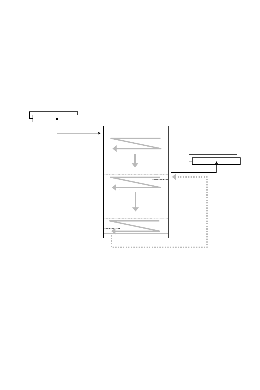
1.3.3. Loop Processing
By setting the LOOP/START bit of the header to 1, the loop point is specified. The header address is
maintained in the LSAXH/L register when sound generation moves to this block, and sound generation moves
to the first sample data of this block after processing the endpoint block.
Only 1 loop point specification can be in effect in a set of waveform data. If there are two or more loop point
blocks, the block closest to the endpoint becomes the loop point when sound is actually generated.
If an address is set in the LSAXH/L register after sound generation has started, the loop point specification in
the waveform data is disregarded until the next time the voice is keyed on, and the set address becomes the loop
point.
For waveform data with a loop point set, the LOOP bit of the header must be set to 1 in all blocks.
Start Block
[SSAH / L]
Loop Point Block
[LSAXH / L]
Endpoint Block
LOOP=1
LOOP=1, LOOP/START=1
LOOP=1, LOOP/END=1
Figure 1-5 Loop Processing

SCE CONFIDENTIAL SPU2 Overview Version 6.0
© SCEI
-17-
1.4. Reset
The sound library provides a resetting feature. In resetting, neither register values nor data in the local memory
is guaranteed.

SCE CONFIDENTIAL SPU2 Overview Version 6.0
© SCEI
-18-
(This page is left blank intentionally)

SCE CONFIDENTIAL SPU2 Overview Version 6.0
© SCEI
-19-
2. Sound Generation
This chapter describes sound generation in each core.
SCE CONFIDENTIAL SPU2 Overview Version 6.0
© SCEI
-20-
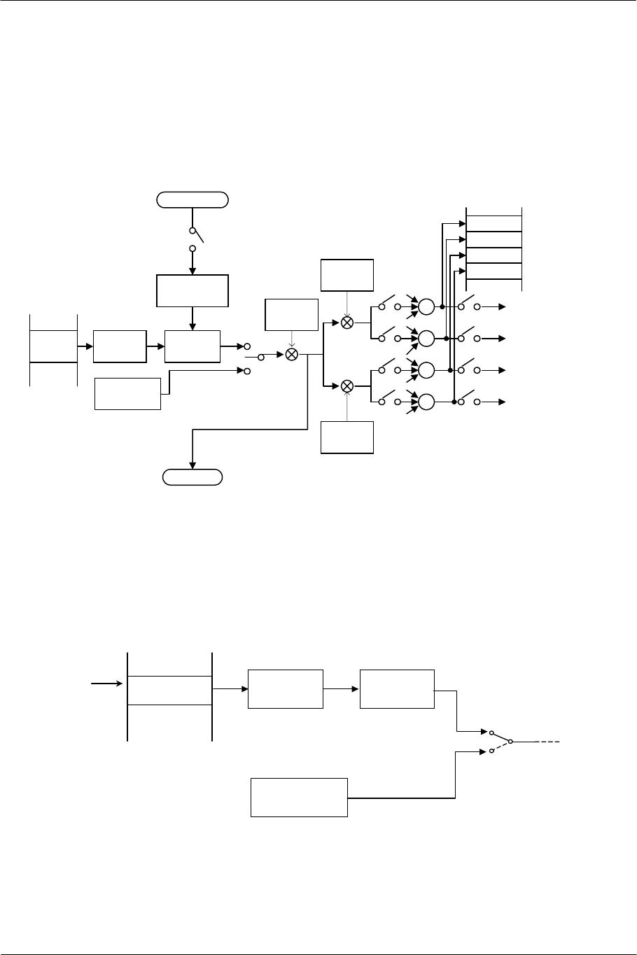
2.1. Voice Processing
Voice processing generates sound primarily by decoding waveform data and varying the decoded sound data by
time.
The generated sound is transferable to the host as data, and can also be processed on the host.
The entire flow of voice processing is shown as follows:
Local Memory
OUTX(i-1)
Pitch
Modulation
Pitch
Control
ADPCM
Decode
Waveform
data
Envelope
Control
Local Memory
[SSAH/L]
[LSAXH/L]
Noise
Generator
[NON]
[PMON]
[PITCH]
[ADSR1]
[ADSR2]
VOL(L)
Control
ƒ°
ƒ°
ƒ°
ƒ°
Dry L
Sound
Data
Output
[VOLL]
[VOLXL]
[VOLR]
VOL(R)
Control
[VOLXR]
[VMIXR]
[VMIXER]
[VMIXEL]
[VMIXL]
[MMIX]
OUTX(i)
Wet L
Dry R
Wet R
Figure 2-1 Voice Processing
2.1.1. Sound Sources
Waveform data stored in the local memory or the noise generator (each core has 1 unit) can be used as a sound
source for each voice. This selection is specified by the NON0/1 register.
Waveform Data
[SSAH / L] ADPCM
Decoding
[PMON0/1]
[PITCH]
[NON0/1]
Local Memory
Pitch
Processing
Noise Generator
Figure 2-2 Switching between Waveform Data and Noise Generator

SCE CONFIDENTIAL SPU2 Overview Version 6.0
© SCEI
-21-
When waveform data is the sound source, the address in the local memory where the waveform data is located is
specified by the SSAH/L register of the voice attribute. Specify the location of the header in the waveform data
block to the SSAH/L register.
Since each voice generates a single tone, it is necessary to vary the pitch of the same sound in two or more
voices to generate a chord. In this case, however, the same waveform data address is specified to the SSAH/L
register in each voice.
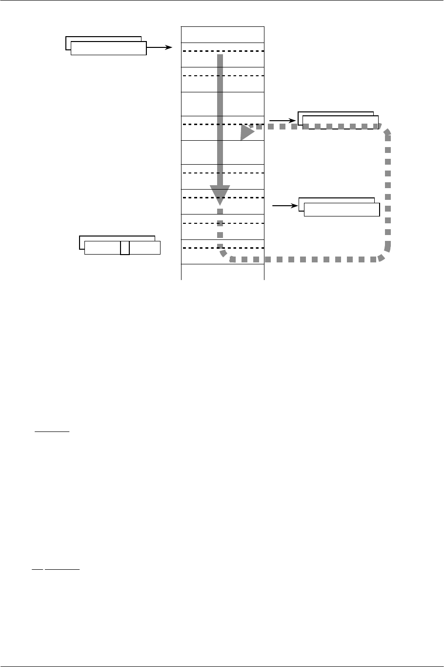
The waveform data is decoded by hardware. The user can know the decoding progress from each of the
following registers:
• Address of the waveform data to be read next (NAXH/L register)
• Header address in the loop point block (LSAXH/L register: after passing the loop point)
• Endpoint block passing flag (ENDX0/1 register)
The NAXH/L register is incremented as decoding advances and shows up to which sample data the sound
generation has been completed. That is, sound processing has been completed up to the address immediately
preceding the one indicated by the NAXH/L register.
Since the waveform data includes the header, however, the above does not mean all the addresses before the one
indicated by the NAXH/L register have been processed. When replacing the sound-generated waveform data,
replacements can be made in block units up to the block immediately before the one having the address
specified by the NAXH/L register. (However, if a replacement is made at a place between the loop point and
endpoint in waveform data including loop processing, decoding becomes discontinuous and might cause a
noise.)
When decoding advances to the loop point block, the header address in the block is written to the LSAXH/L
register. The loop point can be changed by rewriting the value of this register while sound is being generated 4
Ts after the key-on. (Rewriting within 4 Ts is disregarded.) When rewriting, specify the location of the header in
the waveform data block in the LSAXH/L register. After the change, the address in this LSAXH/L register is
used as a loop point, and the loop point information in the header of the waveform data is disregarded until the
next time the voice is keyed on.
When decoding of the endpoint block is finished, regardless of the presence of the loop, the bit corresponding
to the voice is set to 1 in the ENDX register and kept until the next key-on.
SCE CONFIDENTIAL SPU2 Overview Version 6.0
© SCEI
-22-
ENDX0/1
SSAH/L
NAXH/L
1
LSAXH/L
LOOP/START=1
LOOP/END=1
Figure 2-3 Sound Generation Status
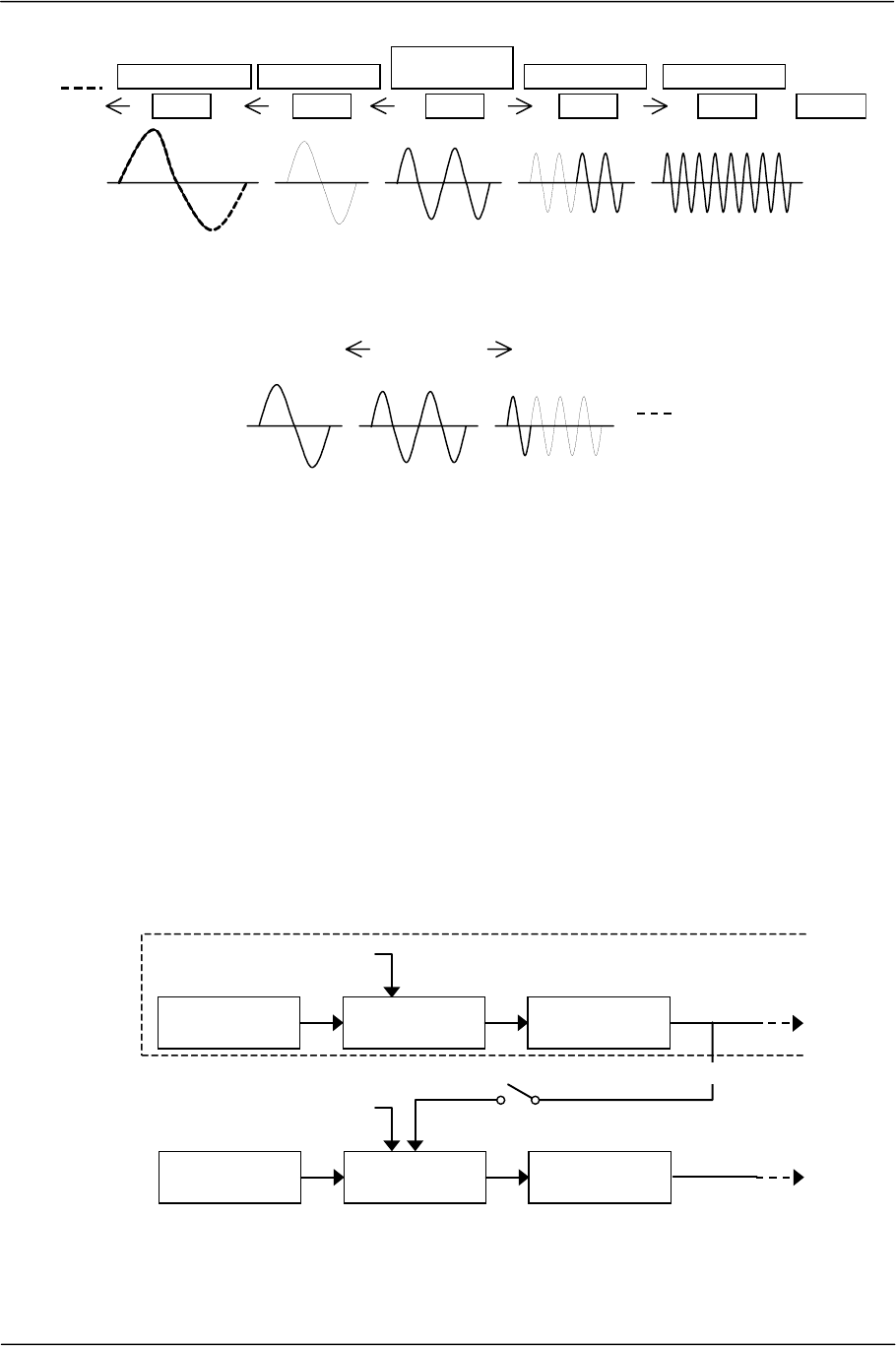
2.1.2. Pitch Transformation
Sound can be generated from waveform data by varying the pitch within the range of -12 to +2 octaves. The
pitch transformation is specified by the PITCH register of voice attribute.
Assuming the original pitch of the sound source is f0, the value of the PITCH register is [PITCH], and the
finally generated sound is f, the following expression is met:
[]
f0
2
PITCH
f 12
=
That is, sound is generated to the pitch of the original sound by specifying 0x1000(=212) in the PITCH register.
The above relationship is met only when the waveform data is sampled at 48 kHz. The sound from waveform
data sampled at a rate other than 48 kHz (24 kHz, for example) is generated one octave higher than the original
sound when specifying 0x1000 in the PITCH register to generate sound.
Assuming the sampling rate to be s kHz, the above-mentioned expression is expanded as follows.
[]
f0
2
PITCH
s
48
f 12
=
If an appropriate value is specified to the PITCH register according to this expression, sound can be generated
to the pitch of the original sound even from the waveform data whose sampling rate is not 48 kHz. However,
the acoustic characteristic varies along with pitch transformation processing.
SCE CONFIDENTIAL SPU2 Overview Version 6.0
© SCEI
-23-
0x400
-2 octaves
0x800
-1 octave
0x1000
Pitch of
Original Sound
0x2000
+1 octave
0x3fff
+2 octaves
[PITCH]
Figure 2-4 Pitch Transformation of Waveform Data Sampled at 48 kHz
0x400
-1 octave
0x800
Pitch of
Original Sound
0x1000
+1 octave
[PITCH]
Figure 2-5 Pitch Transformation of Waveform Data Sampled at 24 kHz
When the sound source is the noise generator, the acoustic pitch can be specified in each core by using the
sound library. When there are two or more voices allocated to the noise generator in each core, their sound will
be all generated at the same acoustic pitch.
The speed of sound generation advance changes with the specification of the pitch. The lower the pitch is set,
the slower the advance in the transition of the waveform data address shown by the NAXH/L register becomes.
2.1.3. Pitch Modulation
In two voices with consecutive voice numbers, voice n can be modulated by using the output value from voice
n-1.
The value used for modulation is the product of the crest value immediately after decoding and the envelope
value in the waveform data for voice n-1, which is 1Ts before in terms of time. This is called the OUTX of
voice n-1. OUTX is not reflected in the register.
Processing
1Ts before
Waveform Data
Decodin
g
[PMON0/1.Vn]
Pitch
Transformation
Envelope
Processin
g
(OUTX)
Waveform Data
Decodin
g
Pitch
Transformation
Envelope
Processin
g
[PITCH]
[PITCH]
V
oice n-1
V
oice n
Figure 2-6 Pitch Modulation
SCE CONFIDENTIAL SPU2 Overview Version 6.0
© SCEI
-24-
Assuming the crest value of voice n-1 used for modulation of voice n to be OUTX and the pitch of voice n to
be P, then P', the value to be used for pitch transformation of voice n, is decided by the following expression.
P' = P (1 + OUTX)
Whether pitch modulation is performed or not can be specified with the PMON0/1 register. When not
performed, the result becomes the same as the case for OUTX=0.
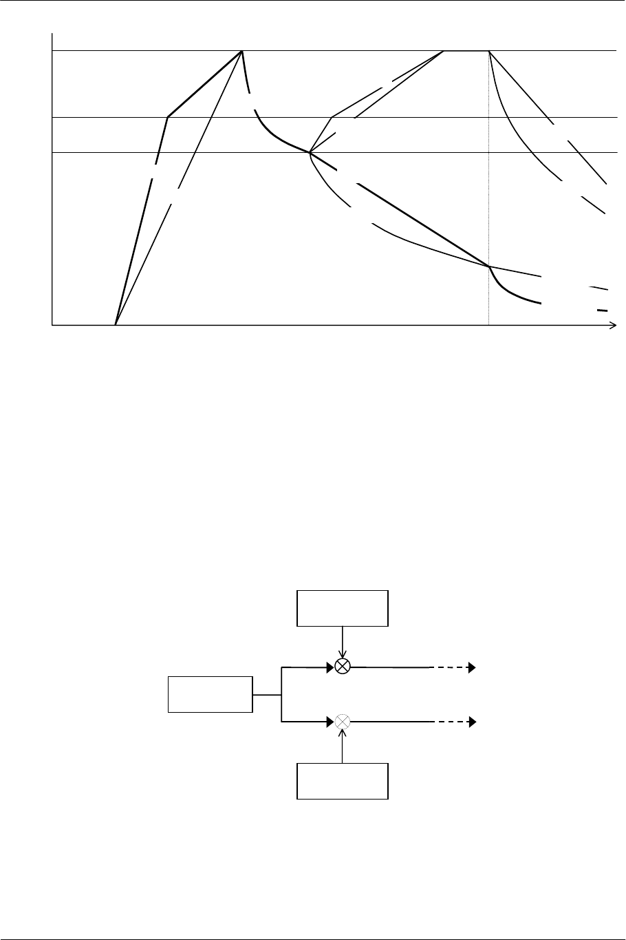
2.1.4. Envelope
The envelope specifies the volume variation by time from key-on to key-off according to the following five
parameters.
Parameter Code Description
Attack Rate AR Rising immediately after key-on
Decay Rate DR Attenuation from the maximum value
Sustain Level SL Transition point from Decay to Sustain
Sustain Rate SR Attenuation (or increment) from Sustain Level
to key-off
Release Rate RR Attenuation after key-off
For Attack Rate, Sustain Rate and Release Rate, curves of variation by time can be selected. Attack Rate and
Release Rate can use two kinds and Sustain Rate can use four kinds of curves as shown in the table below.
Decay Rate is fixed to an exponential decrement curve.
Parameter Selection Set Value
Linear increment (+lin) ADSR1.X=0 Attack Rate
Pseudo exponential increment (+exp) ADSR1.X=1
Linear increment (+lin) ADSR2.Y=000
Linear decrement(-lin) ADSR2.Y=010
Pseudo exponential increment (+exp) ADSR2.Y=100
Sustain Rate
Exponential decrement (-exp) ADSR2.Y=110
Linear decrement (-lin) ADSR2.Z=0 Release Rate
Exponential decrement (-exp) ADSR2.Z=1
The "pseudo exponential increment" is a variation in line, in which linear volume increment is lowered in
increment rate when 75% of the maximum value (0x6000) is exceeded.
SCE CONFIDENTIAL SPU2 Overview Version 6.0
© SCEI
-25-
SL
AR(+exp)
RR(-lin)
DR(-exp)
AR(+lin)
SR(+lin)
SR(-lin)
0.75
1
0t
key-off
key-on
SR(-exp)
SR(+exp)
RR(-lin)
RR(-exp)
RR(-exp)
Figure 2-7 Parameters for Envelope and Their Curves
The value of the envelope varies successively, but the value is reflected in the ENVX register and can be referred
to. When sound is generated from loop-less waveform data, ENVX is set to 0 regardless of the envelope status,
at the moment the ENDX register bit corresponding to the voice is set to 1.
2.1.5. Volume
In each voice, the volume for the L channel and R channel can be set independently. By setting different values,
the panpot can be configured.
The volume settings are made in the VOLL and VOLR registers.
Envelope
Control
[VOLR]
[VOLL]
Volume(L)
Control
Volume(R)
Control
Figure 2-8 Volume Processing
SCE CONFIDENTIAL SPU2 Overview Version 6.0
© SCEI
-26-
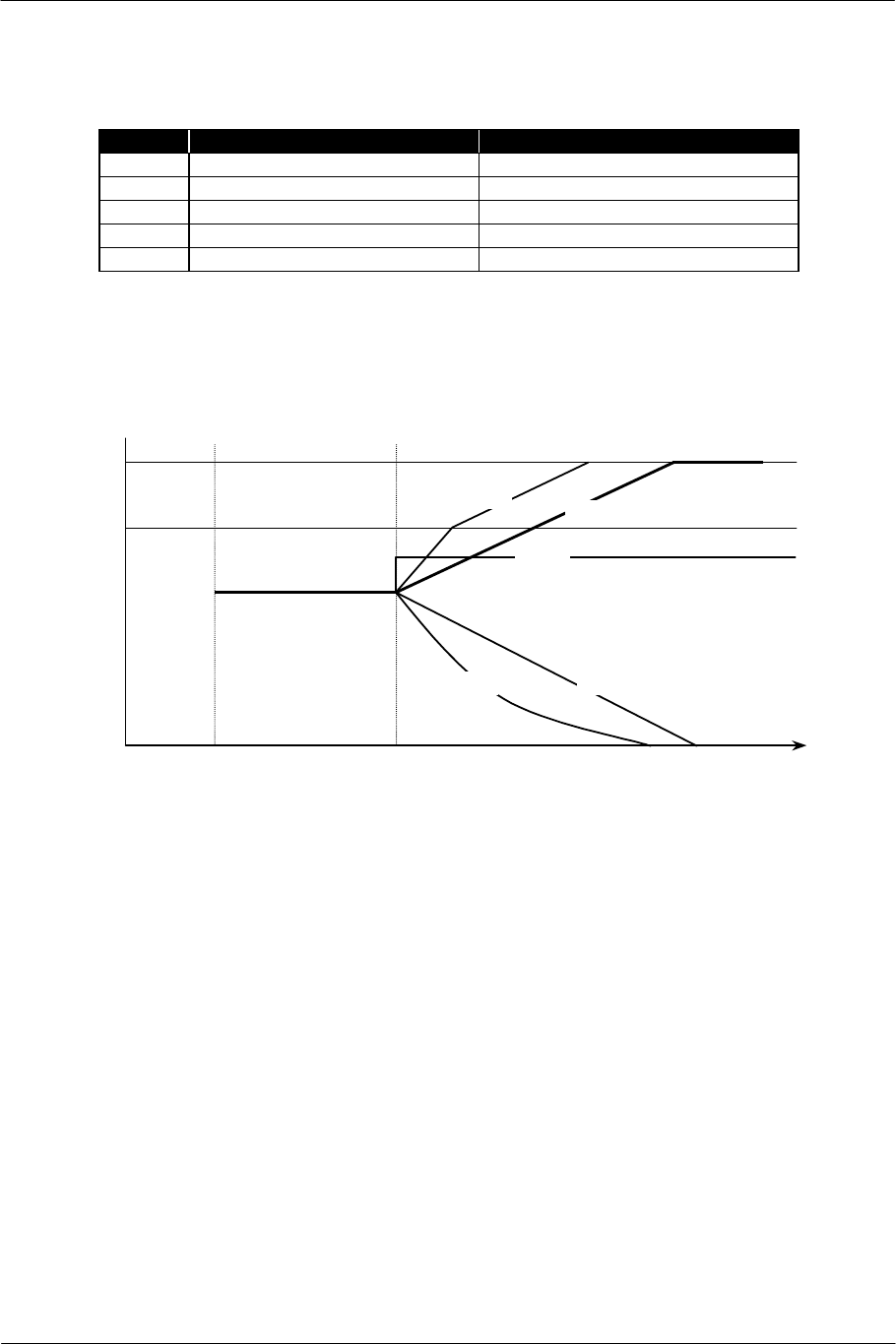
The mode specification, by which the volume varies over time, can be set for the L channel and R channel
independently, as in the case of the Sustain Rate of the envelope.
Mode VOLL/R Register Setting Volume Variation
Direct Bit 15=0 Constant (No variation)
+lin Bit 15:13=100 Linear increment
-lin Bit 15:13=101 Linear decrement
+exp Bit 15:13=110 Pseudo exponential increment
-exp Bit 15:13=111 Exponential decrement
First specify the standard volume in direct mode and start sound generation, even when specifying a mode other
than Direct mode. If a mode other than Direct mode is specified again later with a variation rate, variation of
the volume starts instantly.
The phase can be reversed by setting a negative value in Direct mode.
+lin
-lin
+exp
t
1
0.75
0
-exp
Direct
VOLL/R
Register Setting
Key on
Figure 2-9 Volume Variation by Time
The volume varies successively in modes other than Direct mode, but the value is reflected in the VOLX register
and can be referred to.
2.1.6. Key-On/Key-Off
Key-on (starting sound generation) and key-off (stopping sound generation) can be controlled by the KON0/1
and KOF0/1 registers, respectively, for each voice.
At key-on, sound generation of the waveform data indicated by the SSAH/L register is started according to the
parameters of pitch, envelope, volume, etc.
At key-off, the envelope enters the Release phase and sound generation stops according to the Release Rate.
If there is no loop specification in the waveform data, sound generation of the voice ends when reaching the
endpoint block of waveform data even before key-off, and muting is applied by hardware.
SCE CONFIDENTIAL SPU2 Overview Version 6.0
© SCEI
-27-
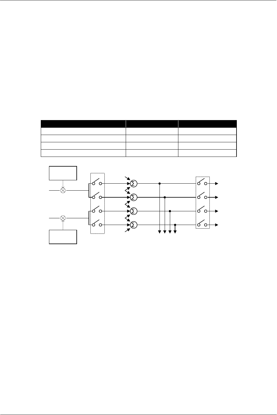
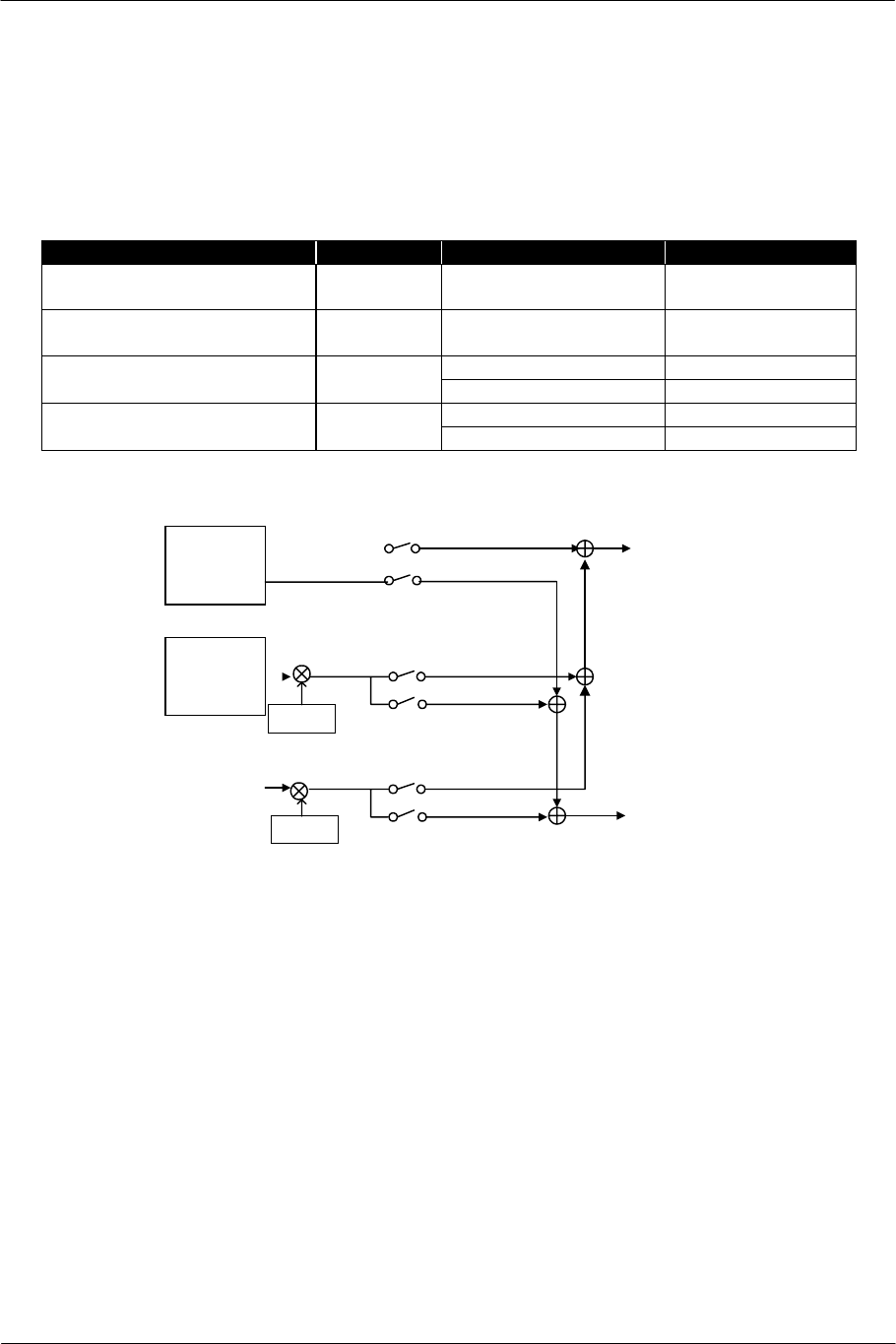
2.1.7. Mixing Switch
The output from each voice is mixed into four channels of Dry L, Wet L, Dry R and Wet R in each core
through the control of the mixing switch.
For the mixing switch, on/off of each voice’s output to the corresponding channels is specified in the
VMIXL0/1, VMIXR0/1, VMIXEL0/1 and VMIXER0/1 registers. When a voice’s output to all the channels is
off, it is equivalent to a voice to which muting is applied.
The mixing results are successively stored in the local memory sound data output area, and become the final
output from the core through switching by the MMIX register at the same time.
For the final output, on/off can be specified for Dry L, Wet L, Dry R and Wet R independently. Turning all the
MMIX switches off is equivalent to applying muting to all the voice outputs.
Channel Mixing Switch Output Switch
Dry L (Voice direct output) VMIXL0/1 MMIX.MSNDL
Dry R (Voice direct output) VMIXR0/1 MMIX.MSNDR
Wet L (Voice effect output) VMIXEL0/1 MMIX.MSNDEL
Wet R (Voice effect output) VMIXER0/1 MMIX.MSNDER
Volume(L)
Control
Volume(R)
Control
[VMIXR]
[VMIXER]
[VMIXEL]
[VMIXL]
[MMIX]
Mixing of
All Voices
to 4 Channels
To Sound Data
Output Area
in Local Memory
Switches for
Mixing Results
Dry L
Mixing
Switches for
Each voice
Wet L
Dry R
Wet R
Figure 2-10 Voice Mixing
SCE CONFIDENTIAL SPU2 Overview Version 6.0
© SCEI
-28-
2.2. Sound Data Input Processing
Successive 16-bit data (little endian) transfer to the local memory sound data input area by the host enables the
SPU2 to apply volume processing to the data as sound data, mix it with the output from voice processing, and
then apply digital effects to it. It is also possible to output the sound data to the output block directly by
bypassing the internal processing in the SPU2.
2.2.1. Sound Data Input Area
Each core is provided with one stereo unit as the sound data input. The addresses in the input area are as
follows. These areas are reserved areas, and other data cannot be placed there.
Address Area Description
2000-21FF CORE0 MEMIN(L) CORE0 L channel sound data input area
2200-23FF CORE0 MEMIN(R) CORE0 R channel sound data input area
2400-25FF CORE1 MEMIN(L) CORE1 L channel sound data input area
2600-27FF CORE1 MEMIN(R) CORE1 R channel sound data input area
The sound data input area is 512 short words (1024 bytes) in size and is composed of double buffers of 256
short words.
Data transfer to the sound data input area can be realized easily by using the Auto DMA write transfer. For
details, refer to the appropriate sound library document.
[MINL/R]
[MINEL/ER]
Volume
Host
[BVOL]
Local Memory
Voice
Processing
Figure 2-11 Sound Data Input
2.2.2. Volume Processing
The volume can be set to the sound obtained from the sound data input with the BVOLL and BVOLR registers.
However, the mode of variation by time cannot be specified and the constant mode is always set.

SCE CONFIDENTIAL SPU2 Overview Version 6.0
© SCEI
-29-
2.2.3. Mixing with Voice Output
The sound obtained from the sound data input can be mixed with the Dry L/Wet L/Dry R/Wet R channel of
the voice output. This is controlled by the flags of the MMIX register.
Sound Data Input Voice Output Switch
MEMIN(L) Dry L MMIX.MINL
MEMIN(R) Dry R MMIX.MINR
MEMIN(EL) Wet L MMIX.MINEL
MEMIN(ER) Wet R MMIX.MINER
2.2.4. Bypass Processing (CORE0)
It is possible to specify a mode that connects directly to the S/PDIF digital output of the output block by
bypassing internal processing, for sound data input to CORE0. Since volume processing is not performed, the
encoded data, which is not ordinary 16-bit digital data, can be directly output from the host.
In this mode, however, CORE1 output, the final output from the core, is not connected to the S/PDIF digital
output. Moreover, this switching is performed only for the S/PDIF digital output and sound data input to
CORE0 cannot be directly connected to the D/A converter output. For details, refer to the appropriate sound
library document.
2.2.5. 32-bit Sound Data Input (CORE1)
It is possible to specify a mode that connects directly to the output block by bypassing the internal processing,
for sound data input to CORE1. In this mode, the sound data input is processed in 32-bit units (24 bits enabled
and lower 8 bits disabled). It can mix the 32-bit data (little endian) transferred from the host as higher quality
digital data with the D/A converter output or the S/PDIF digital output.
The sound data input area is processed in 32-bit units in this mode. Since the unit of data volume doubles, the
speed of data reading also doubles.
For details, refer to the appropriate sound library document.
2.2.6. Monaural Output
The SPU2 does not have the ability to generate monaural sound from the sound obtained from the sound data
input. If monaural output is required, prepare monaural sound data at the authoring level.

SCE CONFIDENTIAL SPU2 Overview Version 6.0
© SCEI
-30-
2.3. Sound Data Output Processing
The SPU2 can write the generated 16-bit sound data to the local memory sound data output area at any time.
Various processes can be applied to the sound data being generated by the SPU2 by reading the data successively
on the host.
The contents of the sound data to be output and the output area are fixed as shown in the table. This area is a
reserved area, and cannot be used for other purposes.
Core Channel Contents Output Area
Voice1 Crest value after multiplication of
envelope in voice1
000400 – 0005FF
Voice3 Crest value after multiplication of
envelope in voice3
000600 – 0007FF
MEMOUT(L) Dry L after mixing 24 voices 001000 – 0011FF
MEMOUT(R) Dry R after mixing 24 voices 001200 – 0013FF
MEMOUT(EL) Wet L after mixing 24 voices 001400 – 0015FF
CORE0
MEMOUT(ER) Wet R after mixing 24 voices 001600 – 0017FF
SIN(L) CORE0 output L 000800 – 0009FF
SIN(R) CORE0 output R 000A00 – 000BFF
Voice1 Crest value after multiplication of
envelope in voice1
000C00 – 000DFF
Voice3 Crest value after multiplication of
envelope in voice3
000E00 – 000FFF
MEMOUT(L) Dry L after mixing 24 voices 001800 – 0019FF
MEMOUT(R) Dry R after mixing 24 voices 001A00 – 001BFF
MEMOUT(EL) Wet L after mixing 24 voices 001C00 – 001DFF
CORE1
MEMOUT(ER) Wet R after mixing 24 voices 001E00 – 001FFF
SCE CONFIDENTIAL SPU2 Overview Version 6.0
© SCEI
-31-
(Reserved)
CORE0 Voice1
CORE0 Voice3
CORE1 SIN(L)
CORE1 SIN(R)
CORE1 Voice1
CORE1 Voice3
CORE0 MEMOUT(L)
CORE0 MEMOUT(R)
CORE0 MEMOUT(EL)
CORE0 MEMOUT(ER)
CORE1 MEMOUT(L)
CORE1 MEMOUT(R)
CORE1 MEMOUT(EL)
CORE1 MEMOUT(ER)
Local Memory
Voice
Processin
g
Host
Mixing
Voice
Processing
Mixing
Output Block
00 0000
00 0400
00 1FFF
Figure 2-12 Sound Data Output
The output area is 512 short words (1024 bytes) in size for each channel, and is composed of double buffers of
256 short words each.
Data can be read easily from the sound data output area by using the Auto DMA read transfer. For details, refer
to the appropriate sound library document.
SCE CONFIDENTIAL SPU2 Overview Version 6.0
© SCEI
-32-
2.4. Mixing
Mixing performs volume processing and switching to voice output, sound data input and external input, and
distributes the data to direct output and digital effects.
Each core has the following four sources:
Source Volume Switch Destination
Voice Direct Output
(Dry L/R)
- MMIX.MSNDL/R Direct Output
Voice Effect Output
(Wet L/R)
- MMIX.MSNDEL/ER Digital Effect
MMIX.MINL/R Direct Output Sound Data Input BVOLL/R
MMIX.MINEL/ER Digital Effect
MMIX.SINL/R Direct Output External Input
(Final Output from CORE0)
AVOLL/R
MMIX.SINEL/ER Digital Effect
* External input is performed only to CORE1.
Voice
Processing
Sound Data
Input
External
Input
[MSNDL/R]
[MSNDEL/ER]
[MINL/R]
[MINEL/ER]
[SINL/R]
[SINEL/ER]
Volume
Volume
[BVOL]
[AVOL]
To Direct
Output
To Digital
Effect
Dry L/R
Wet L/R
Figure 2-13 Mixing
For sound data input and external input, only the constant mode is set for volume variation with time.
SCE CONFIDENTIAL SPU2 Overview Version 6.0
© SCEI
-33-
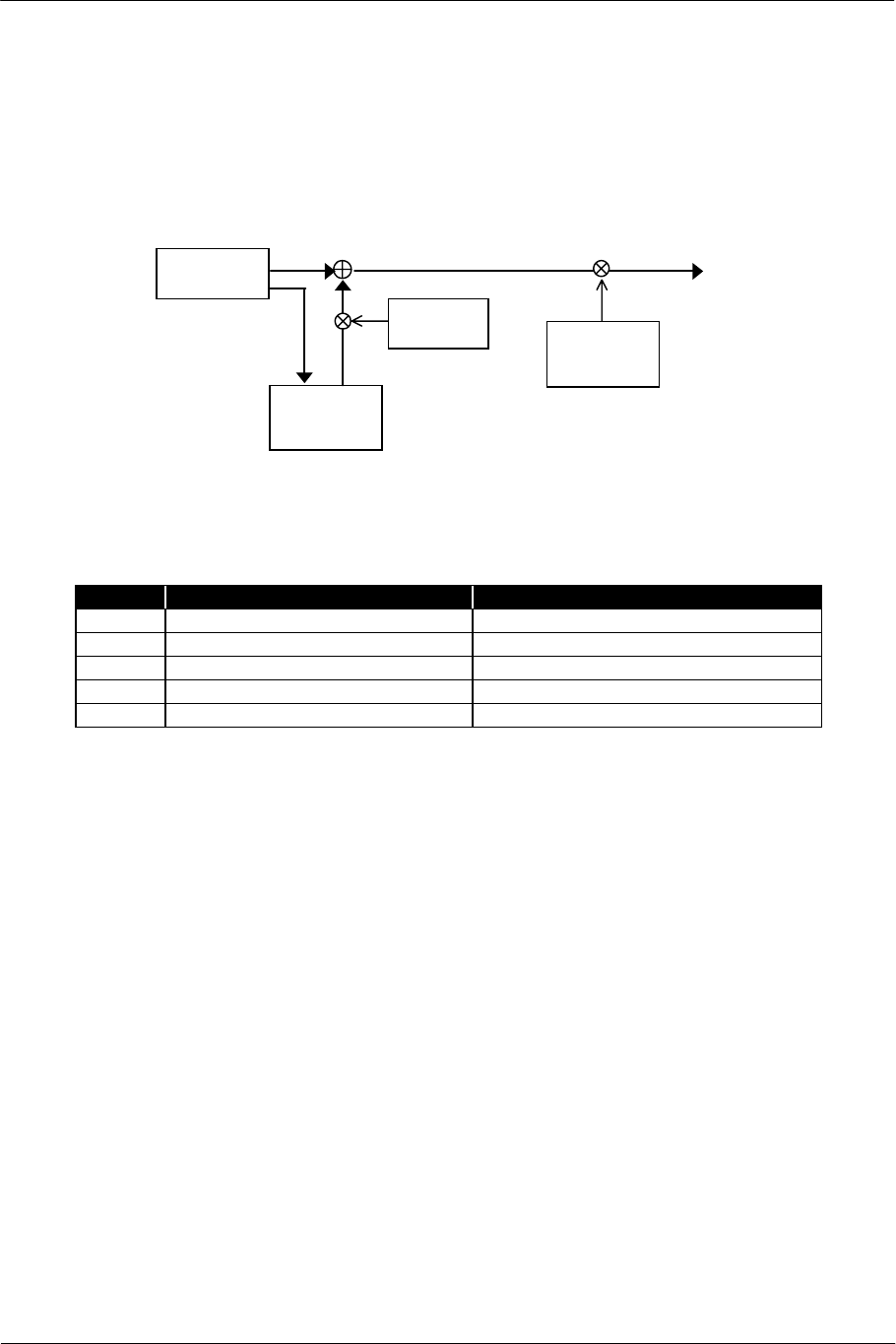
2.5. Digital Effect Processing
Various sound effects such as reverb, echo and delay can be added by performing digital effect processing on the
sounds generated by each core and input from the sound data input.
For other digital effect procedures, refer to the sound library document.
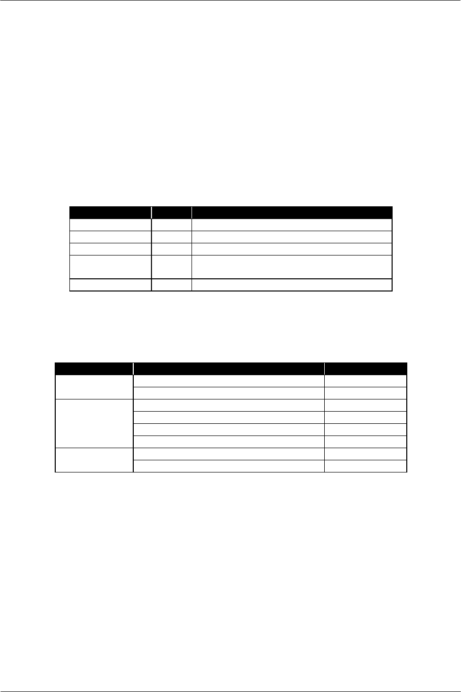
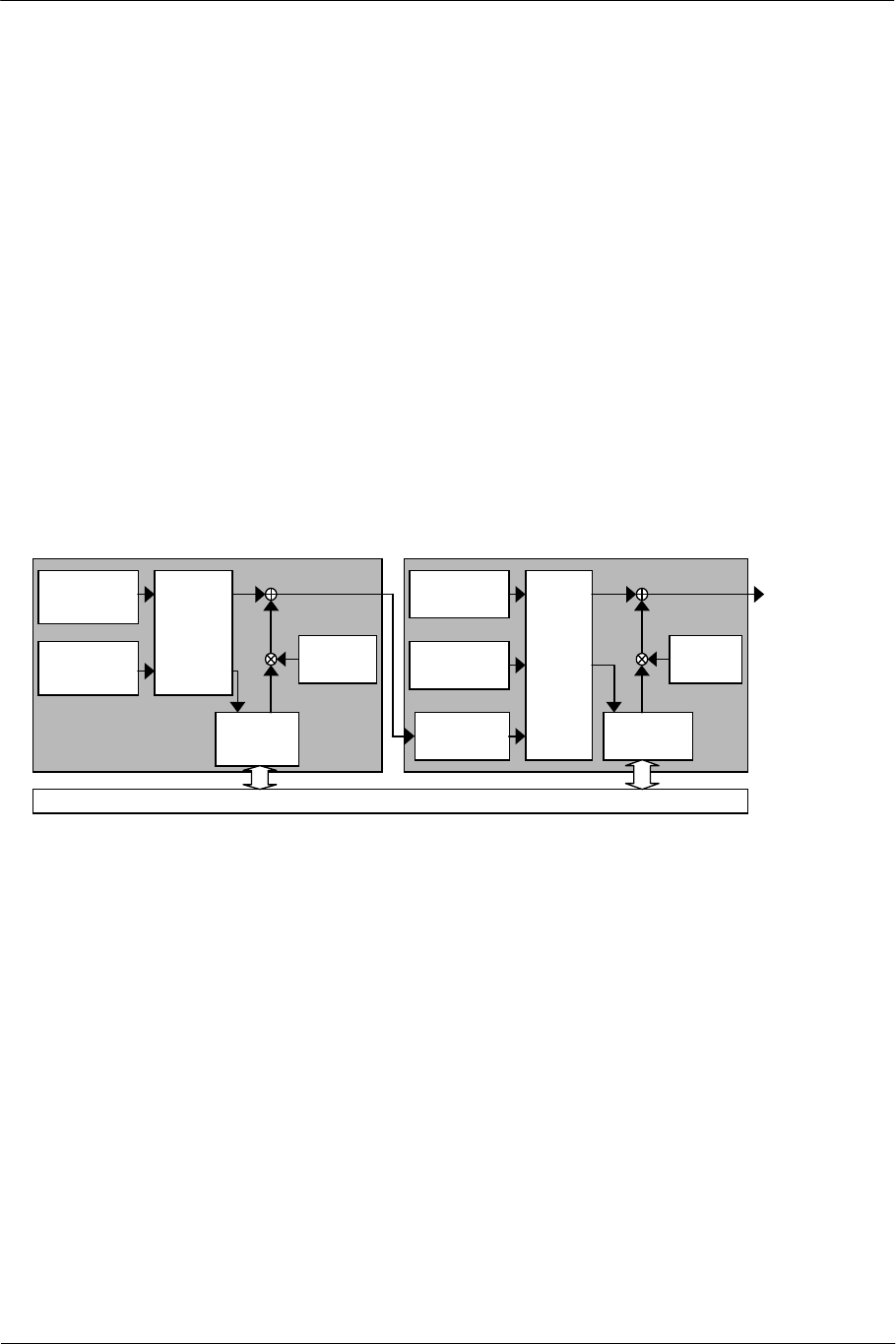
2.5.1. Signal Flow for Digital Effect Processing
The input to digital effect processing is the mixture of the following sound sources as described in "2.4. Mixing".
• Voice Effect Output (Wet L/R)
• Sound Data Input
• External Input *CORE1 only
However, various connection forms can be taken by passing through the host with switch on/off setting and
sound data output function.
Voice
Processing
Sound
Data Input
Mixing
Digital
Effect
Effect
Volume
[EVOL]
Voice
Processing
Digital
Effect
[EVOL]
External
Input
To
Output
Block
Local Memory
CORE0 CORE1
Sound
Data Input
Mixing Effect
Volume
Figure 2-14 Signal Flow of Digital Effects
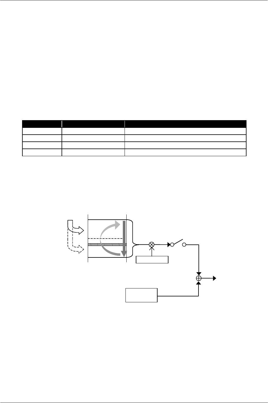
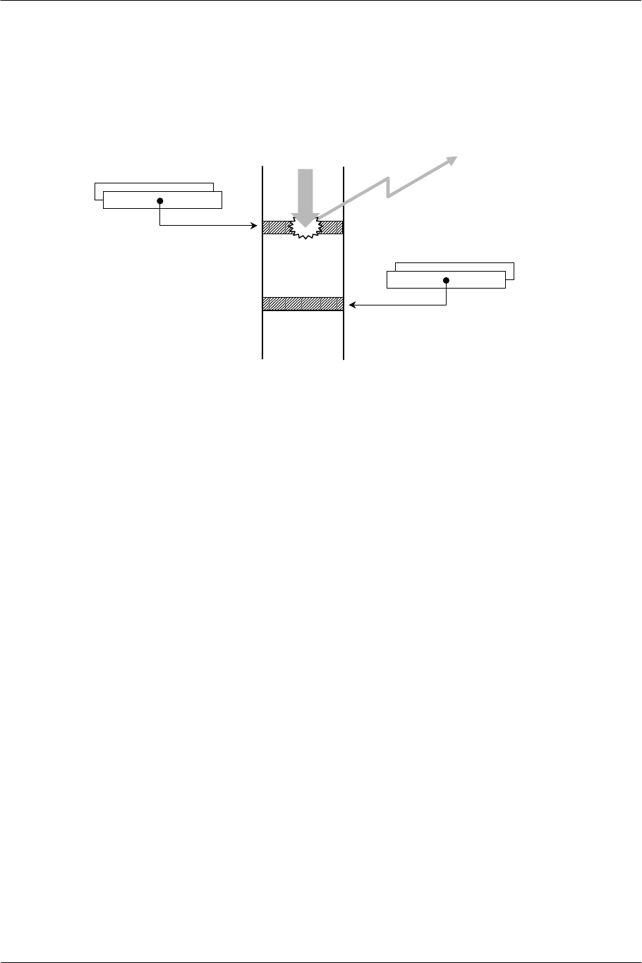
2.5.2. Work Area for Digital Effect Processing
When performing digital effect processing, it is necessary to reserve a work area in the local memory.
The start address of the work area is specified with the ESAH/L register and the end address is specified with
the EEAH register.
Decide the start address by totaling the size required by each delay block for digital effects.
The end address is specified in the upper 6 bits only, and it is assumed that the lower 16 bits are 0xFFFF. That
is, the end address in the work area is always on a 64K short-word (128 KB) boundary in the local memory.
SCE CONFIDENTIAL SPU2 Overview Version 6.0
© SCEI
-34-
0? FFFF
CORE0
[ESAH / L]
CORE1
[ESAH / L]
Digital Effect
Work Area
for CORE0
0? FFFF
CORE0
[EEAH]
CORE1
[EEAH]
Digital Effect
Work Area
for CORE1
Figure 2-15 Work Area for Digital Effects
2.5.3. Effect Volume
When the output from a digital effect is mixed with the direct output, volume control can be performed to the
output from the digital effect.
The effect volume is set with the EVOLL/R register. The panpot of the effect can be decided by setting the L
channel and R channel independently. Only the constant mode is set for the variation with time.
The volume set by the EVOLL/R register corresponds to the return volume of the effect. The following
volume settings of each source correspond to the send volume respectively.
Source Send Volume Remarks
Voice Output VOLL/R
Sound Data Input BVOLL/R
External Input AVOLL/R CORE1 only
SCE CONFIDENTIAL SPU2 Overview Version 6.0
© SCEI
-35-
2.6. Master Volume
The final volume is determined by adding the master volume to the mixing result of the output from the digital
effect and direct output (Dry L/R). The master volume of the L channel and R channel can be set
independently by the MVOLL and MVOLR register. By setting the values, the whole panpot is decided.
Mixing
[MVOLL/R]
To
Out
p
ut
Digital
Effect
Master
Volume
[EVOLL/R]
Effect
Volume
Figure 2-16 Master Volume Processing
The mode of varying the master volume with time can be specified as follows, as well as the voice volume:
Mode MVOLL/R Register Setting Volume Variation
Direct Bit 15=0 Constant (no variation with time)
+lin Bit 15:13=100 Linear increment
-lin Bit 15:13=101 Linear decrement
+exp Bit 15:13=110 Pseudo exponential increment
-exp Bit 15:13=111 Exponential decrement
The L channel and R channel can be specified independently for the volume mode as well.
When specifying a mode other than "Direct", first specify the standard volume value in Direct mode. Then, the
volume variation starts when other volume mode variation rates are re-specified. Moreover, the phase can be
reversed by specifying a negative value as a variation rate.
The current value of the master volume can be read from the MVOLXL/MVOLXR register.
SCE CONFIDENTIAL SPU2 Overview Version 6.0
© SCEI
-36-
2.7. Interrupt Processing
In most SPU2 processing, when each core accesses a specific address in the local memory, an interrupt can be
generated to the host. The address where an interrupt is generated is set by the IRQAH and IRQAL registers.
Interrupt to Host
CORE 0
[IRQAH / L]
Local Memory
Arbitrary
Processing
CORE 1
[IRQAH / L]
Figure 2-17 Interrupt Processing
No matter which core accesses this address, an interrupt is generated. Interrupts generated by both cores are
detected at the same time on the host. An interface provided by the sound library represents which core has
generated the interrupt.
In the following situations, there are limitations and warnings applied to the relationship between each core's
access and interrupts.
Initial state and waveform data without a loop
Voices without key-on after resetting the SPU2, and voices generated after decoding the LOOP/END block
of loop-less waveform data, access the local memory unnecessarily (free-run the entire local memory area) as
an internal operation of the SPU2. This may cause an unexpected interrupt.
Therefore, when applying an interrupt to loop-less waveform data, suppress unnecessary accesses from a
voice not in process, by adding a soundless block whose LOOP/START, LOOP, and LOOP/END bits are
set to 1 to the end of the data. (For waveform data format, refer to "1.3. Waveform Data Format".) Actions
for the voices to which key-on has not been applied after resetting are handled via the sound library.
Position of waveform data which sets interrupt generation address
If an address between the starting and end addresses in waveform data is specified to the SSAH/L or
LSAXH/L register by mistake and the IRQA/H register is specified to the same address, an interrupt does
not occur.
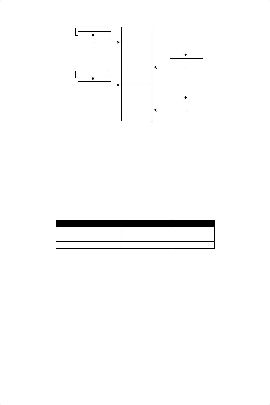
Local memory data transfer
When local memory data transfer is performed, the internal pointer stays at the following addresses at the
end of the transfer:
Transfer from host to local memory: TSAH/L + Data Size + 1
Transfer from local memory to host: TSAH/L + Data Size + 0 x 20
(Both are in short-word units)

SCE CONFIDENTIAL SPU2 Overview Version 6.0
© SCEI
-37-
Therefore, if the IRQAH/L register has been set at these positions, an interrupt occurs after the transfer has
been ended.
Digital effect processing
When digital effect processing is disabled, interrupts by digital effect processing are not generated even if the
interrupt generation address is specified to the digital effect work area.

SCE CONFIDENTIAL SPU2 Overview Version 6.0
© SCEI
-38-
(This page is left blank intentionally)

SCE CONFIDENTIAL SPU2 Overview Version 6.0
© SCEI
-39-
3. Register List

SCE CONFIDENTIAL SPU2 Overview Version 6.0
© SCEI
-40-
3.1. Classification of Registers
The registers of the SPU2 are classified as follows:
Voice basic parameter registers
These registers show the basic parameters of each voice. Each voice in each core has a set of registers.
Voice control parameter registers
These registers control on/off of each function in voice processing. Each core has a set of registers.
Addressing registers
These registers perform address specification in the local memory. The registers, which show the upper 6
bits and the lower 16 bits in the address, are paired. Each core has a set of registers.
Digital effect addressing registers
These registers perform addressing related to digital effects. The registers, which show the upper 6 bits and
the lower 16 bits in the address, are paired. Each core has a set of registers.
Volume registers
These registers specify the mixing volume of each voice. Each core has a set of registers.

SCE CONFIDENTIAL SPU2 Overview Version 6.0
© SCEI
-41-
3.2. Registers in Pairs
The SPU2 registers include registers to be used in pairs.
Addresses in the local memory are specified by a pair of registers showing the upper 6 bits and the lower 16 bits
of one address. For example, the starting address of the waveform data for each voice is maintained in the
SSAH register (the upper 6 bits) and the SSAL register (the lower 16 bits). Therefore, SSAH and SSAL are
treated as a pair and written as the SSAH/L register.
The EEAH register is an exception to the addressing registers, and does not include a register which shows the
lower 16 bits.
Registers that specify the switching for each voice are composed of a pair of registers corresponding to Voice 0-
15 and Voice 16-23. As for the specification of the voice output to the Dry L channel, for example, Voice0-15
and Voice16-23 are specified by the VMIXL0 register and VMIXL1 register respectively. These two registers
are treated as a pair and written as the VMIXL0/1 register.
SCE CONFIDENTIAL SPU2 Overview Version 6.0
© SCEI
-42-
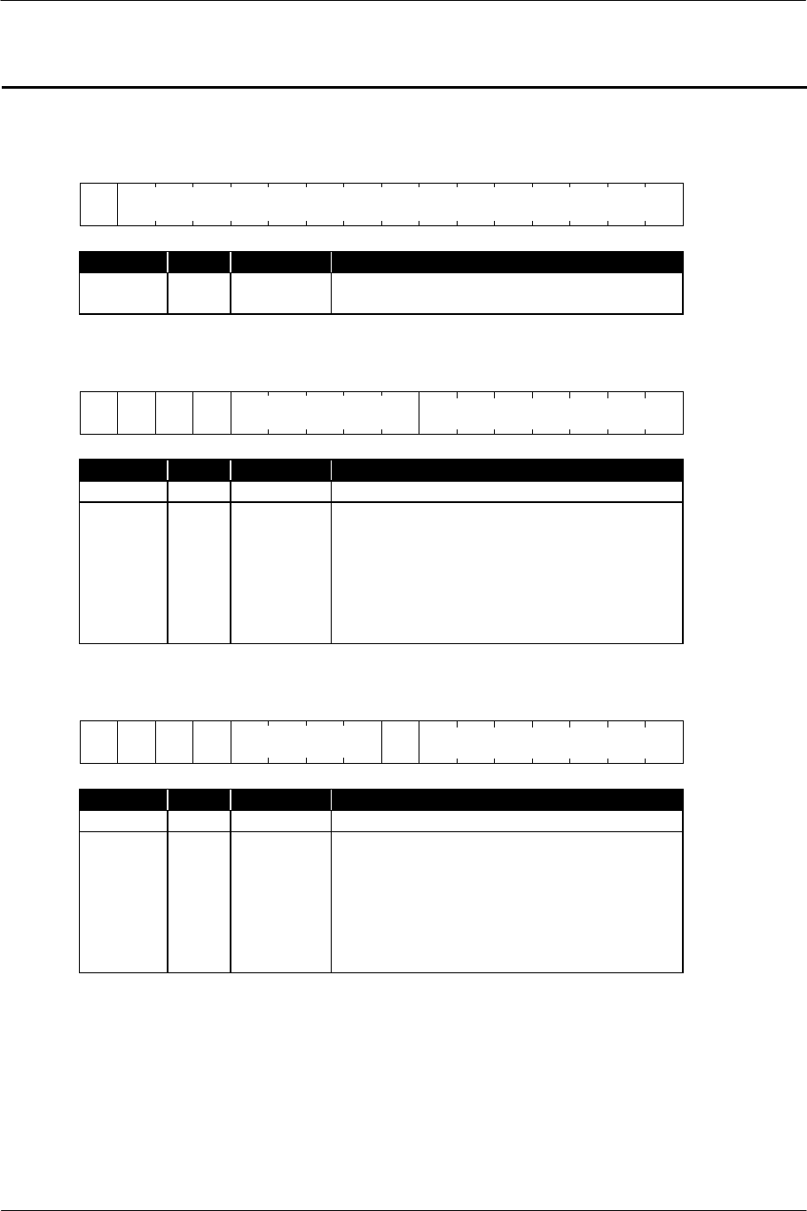
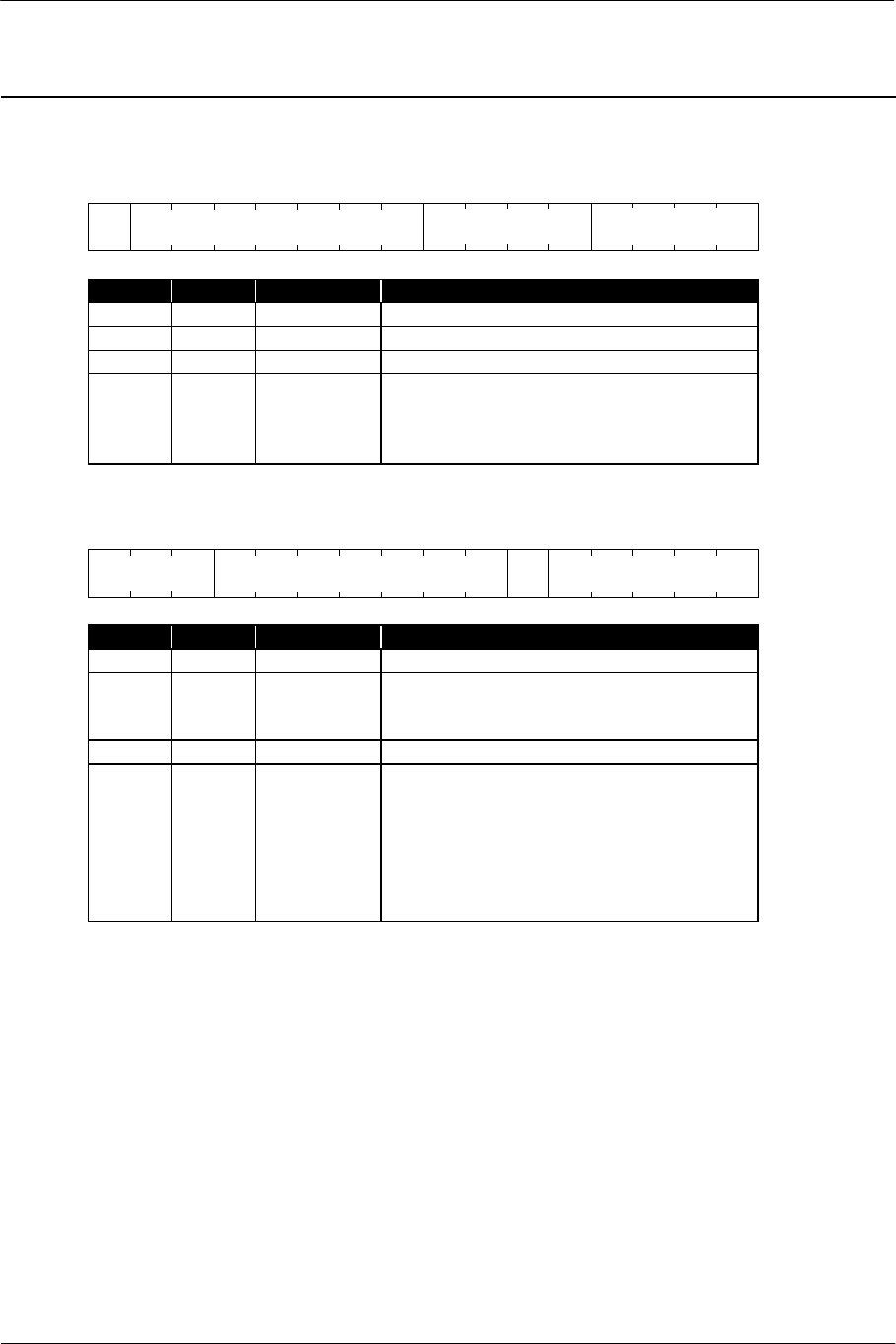
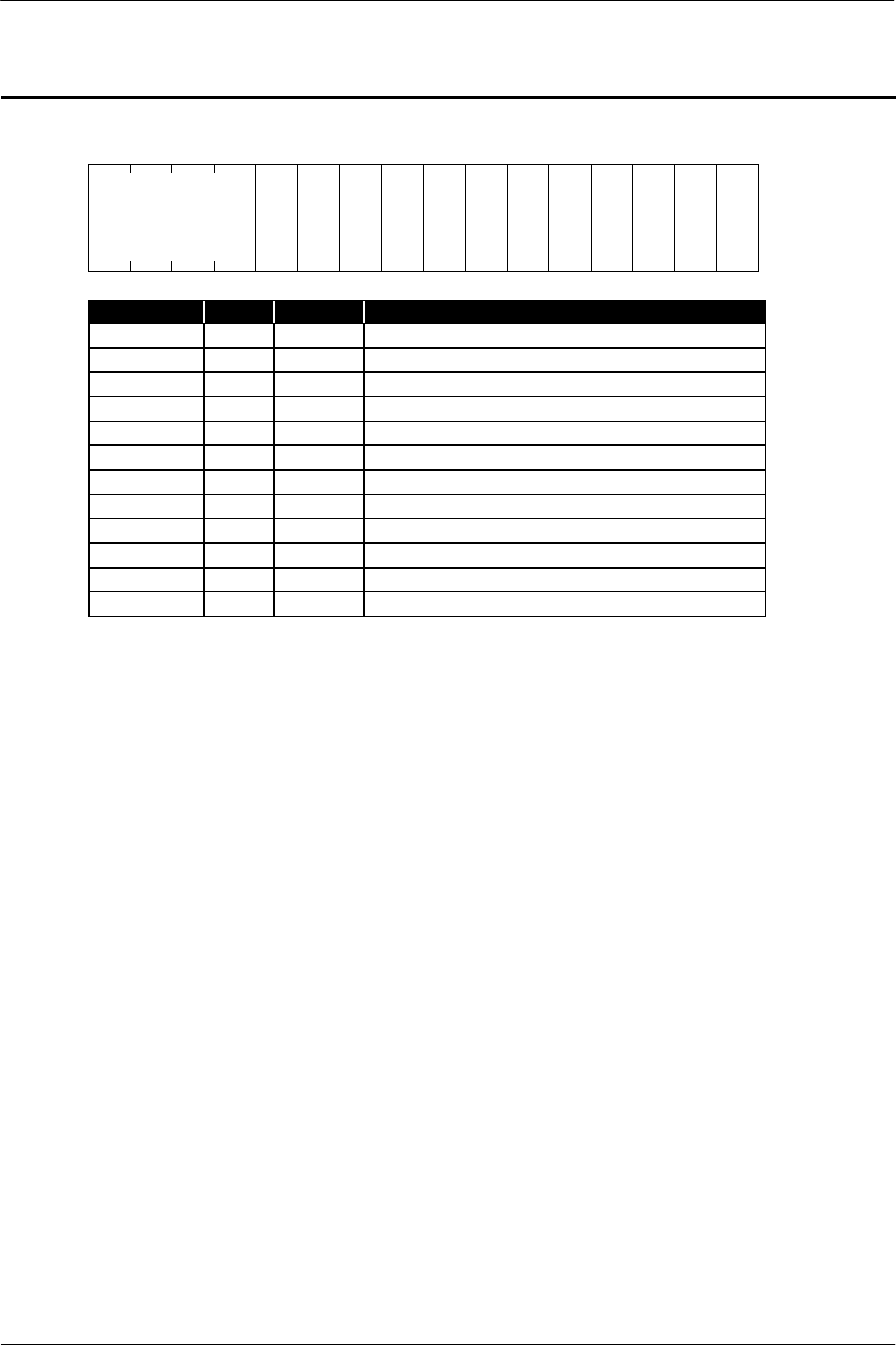
VOLL / VOLR : Voice volume
Constant specification mode (direct mode)
15 12 8 4 0
0
Name Pos. Format Contents
VALUE 14:0 int 1:0:14 Constant volume value
The phase reverses for a negative value.
Linear increment mode (+lin mode)
15 12 8 4 0
1 0 0 X
Name Pos. Format Contents
VALUE 6:0 int 0:7:0 Addition constant per Ts
X 12 int 0:1:0 Polarity specification
0 Normal phase (specifiable when the current
value is positive.)
Linear increment to +1.0
1 Reverse phase (specifiable when the current
value is negative.)
Linear decrement to –1.0
Linear decrement mode (-lin mode)
15 12 8 4 0
1 0 1 X 0
Name Pos. Format Contents
VALUE 6:0 int 0:7:0 Subtraction constant per Ts
X 12 int 0:1:0 Polarity specification
0 Normal phase (specifiable when the current
value is positive.)
Linear decrement to 0
1 Reverse phase (specifiable when the current
value is negative.)
Linear increment to 0
VALUE
VALUE
(reserved)
VALUE
(reserved)
SCE CONFIDENTIAL SPU2 Overview Version 6.0
© SCEI
-43-
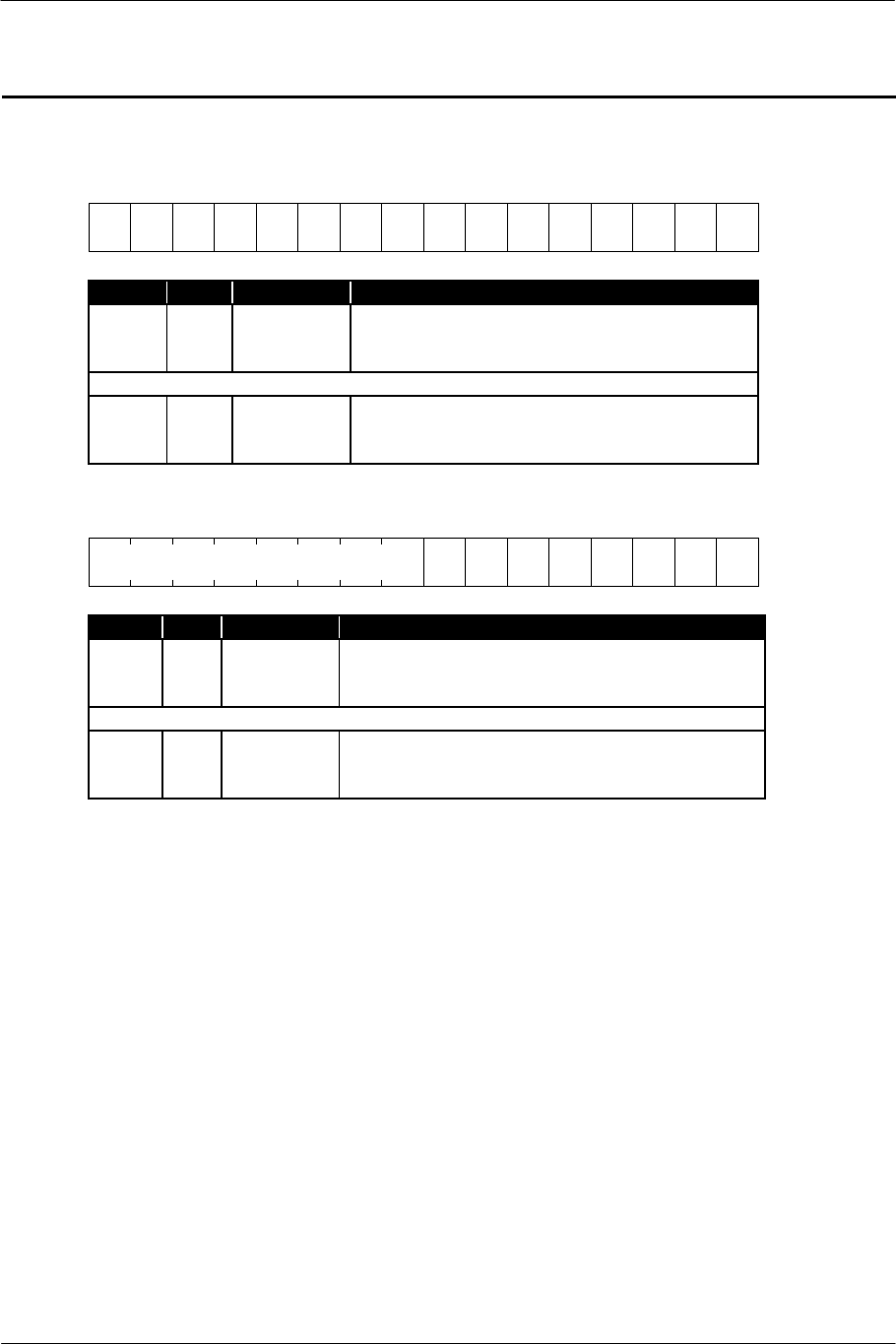
Pseudo inverse-exponential increment mode (+exp mode)
15 12 8 4 0
1 1 0 X 0
Name Pos. Format Contents
VALUE 6:0 int 0:7:0 Addition constant per Ts
X 12 int 0:1:0 Polarity specification
0 Normal phase (specifiable when the current
value is positive.)
Increment to +1.0 in a line
1 Reverse phase (specifiable when the current
value is negative.)
Decrement to –1.0 in a line
Exponential decrement mode (-exp mode)
15 12 8 4 0
1 1 1 0
Name Pos. Format Contents
VALUE 6:0 int 0:7:0 Multiplication constant per Ts
Description
These registers specify the volume for each voice.
The values of the upper three bits specify the pattern of the volume variation with time. When specifying a
mode other than constant mode, the volume value varies with time, because the value corresponding to the
value of the VALUE field is added to, subtracted from or multiplied by the volume value per Ts.
For the relationship between the VALUE field value and actual volume duration, refer to "4.1. Rate
Parameter Table".
VALUE
(reserved)
VALUE
(reserved)

SCE CONFIDENTIAL SPU2 Overview Version 6.0
© SCEI
-44-
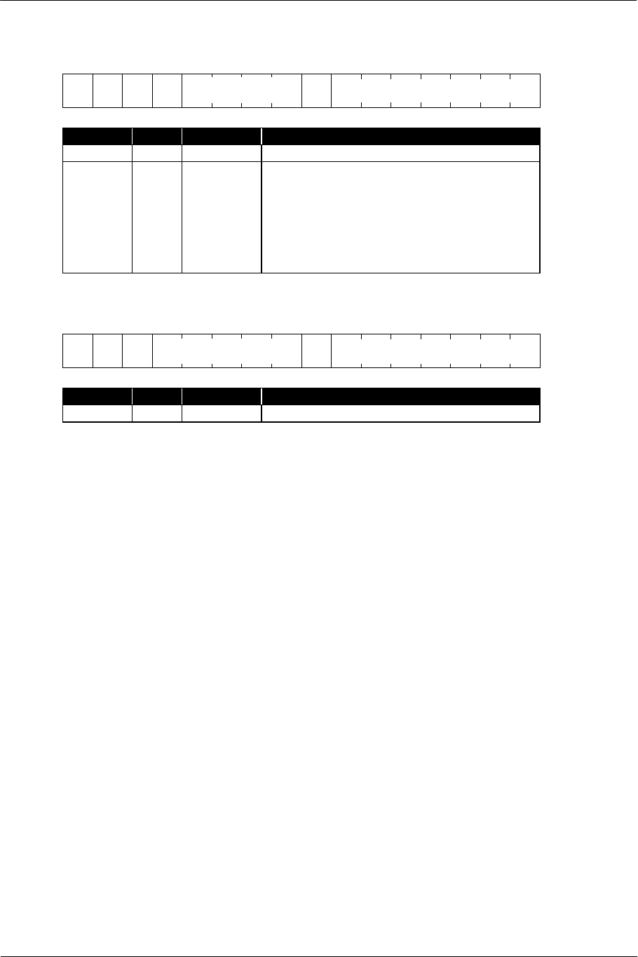
PITCH : Pitch when sound is generated
15 12 8 4 0
0 0
Name Pos. Format Contents
VALUE 13:0 int 0:14:0 Pitch specification value
Description
This register specifies the pitch (degree of highness or lowness of sound) of each voice.
Assuming the pitch of the original sound (waveform data) to be f0, the relationship between the VALUE, or
the pitch specification, and the pitch f, from which sound is generated, is as follows:
f0
4096
VALUE
f=
When the sound source is a noise generator, there is no acoustic variation even though the pitch
specification is changed. The pitch of the noise can be specified for each core by using the sound library.
Notes
Pitch specification affects the progressing speed of sound generation. The lower the pitch is specified, the
slower the sound generation proceeds.
VALUE
SCE CONFIDENTIAL SPU2 Overview Version 6.0
© SCEI
-45-
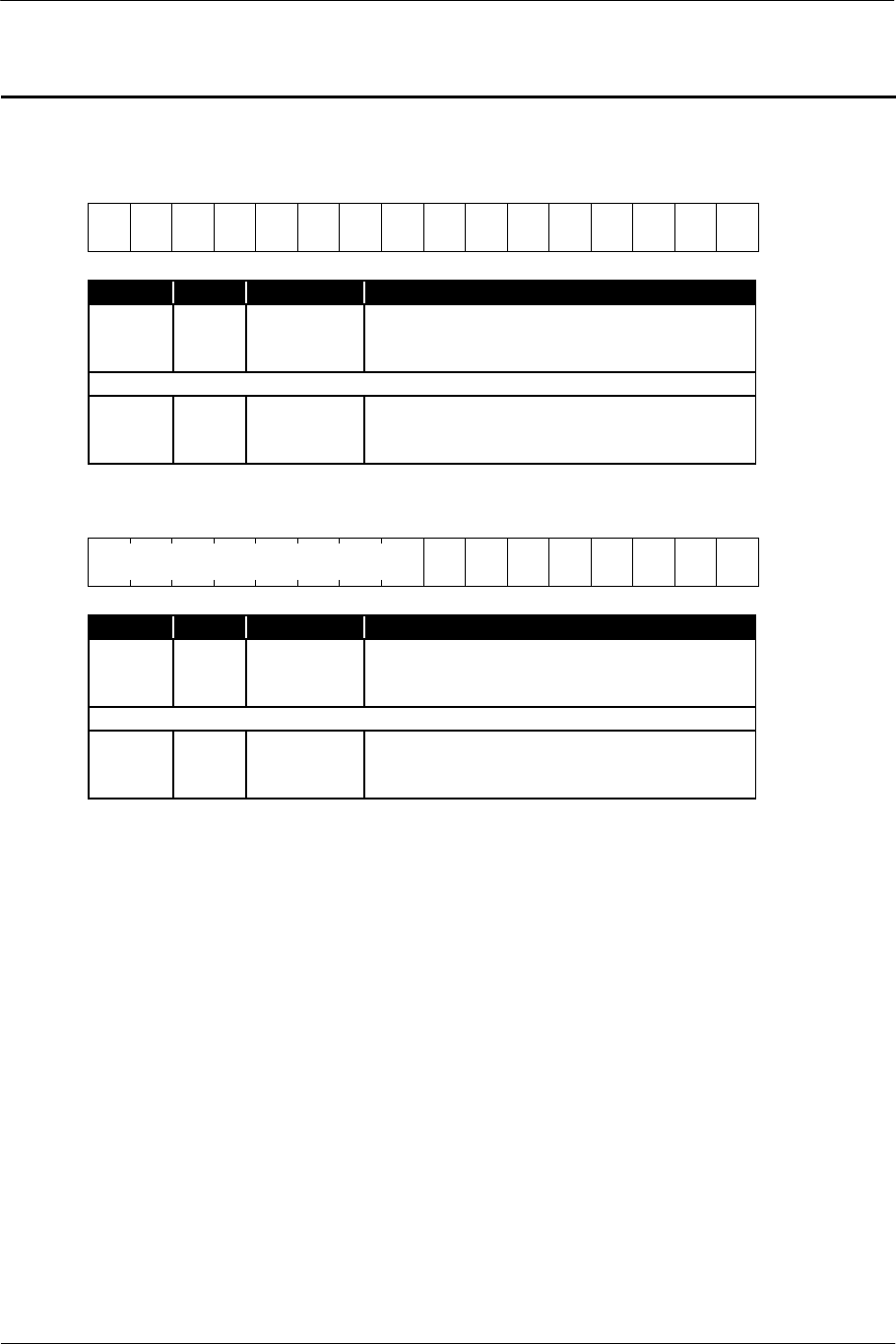
ADSR1 / ADSR2 : Envelope
ADSR1
15 12 8 4 0
X
Name Pos. Format Contents
SL 3:0 int 0:4:0 Sustain Level
DR 7:4 int 0:4:0 Decay Rate
AR 14:8 int 0:7:0 Attack Rate
X 15 int 0:1:0 Mode specification for Attack Rate
0 Linear increment mode (+lin mode)
1 Pseudo exponential increment mode
(+exp mode)
ADSR2
15 12 8 4 0
Z
Name Pos. Format Contents
RR 4:0 int 0:5:0 Release Rate
Z 5 int 0:1:0 Mode specification for Release Rate
0 Linear decrement mode (-lin mode)
1 Exponential decrement mode (-exp mode)
SR 12:6 int 0:7:0 Sustain Rate
Y 15:13 int 0:3:0 Mode specification for Sustain Rate
000 Linear increment mode (+lin mode)
010 Linear decrement mode (-lin mode)
100 Pseudo exponential increment mode
(+exp mode)
110 Exponential decrement mode
(-exp mode)
Description
These registers specify each parameter for the envelope.
For the relationship between the Rate/Level field values and actual envelope duration, refer to "4.1. Rate
Parameter Table".
AR DR SL
SR
Y RR

SCE CONFIDENTIAL SPU2 Overview Version 6.0
© SCEI
-46-
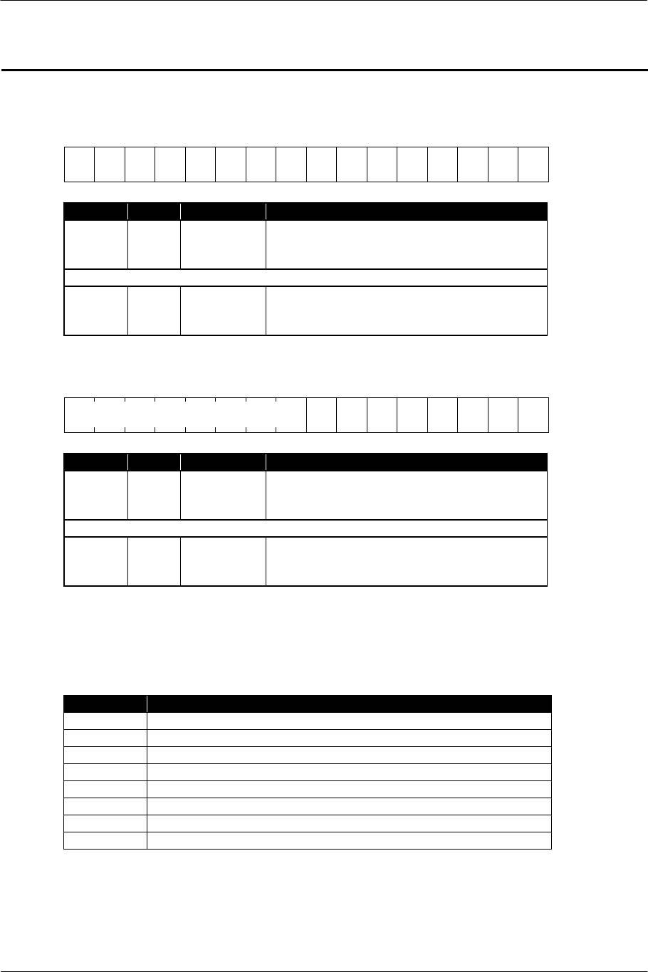
ENVX : Current value of envelope
15 12 8 4 0
Name Pos. Format Contents
VALUE 15:0 int 1:0:15 Current value of envelope
Description
This register indicates the current value of the envelope.
When SR and RR for the envelope specify linear decrement, a negative value is set only for 1 Ts.
When sound is generated from loop-less waveform data, ENVX is set to 0 regardless of the envelope status,
at the moment the ENDX register bit corresponding to the voice is set to 1.
VALUE

SCE CONFIDENTIAL SPU2 Overview Version 6.0
© SCEI
-47-
VOLXL / VOLXR : Current value of volume
15 12 8 4 0
Name Pos. Format Contents
VALUE 15:0 int 1:0:15 Current value of voice volume
Description
These registers indicate the current volume of each voice.
When VOL is in a mode other than constant specification mode, the value varies per Ts according to the
volume variation.
VALUE
SCE CONFIDENTIAL SPU2 Overview Version 6.0
© SCEI
-48-
PMON0 / PMON1 : Pitch modulation specification
PMON0
15 12 8 4 0
V
15
V
14
V
13
V
12
V
11
V
10
V
9
V
8
V
7
V
6
V
5
V
4
V
3
V
2
V
1
-
Name Pos. Format Contents
V1 1 int 0:1:0 Pitch modulation specification for Voice1
0 Pitch modulation off
1 Pitch modulation by Voice0 output
(Omitted)
V15 15 int 0:1:0 Pitch modulation specification for Voice15
0 Pitch modulation off
1 Pitch modulation by Voice14 output
PMON1
15 12 8 4 0
V
23
V
22
V
21
V
20
V
19
V
18
V
17
V
16
Name Pos. Format Contents
V16 0 int 0:1:0 Pitch modulation specification for Voice16
0 Pitch modulation off
1 Pitch modulation by Voice15 output
(Omitted)
V23 7 int 0:1:0 Pitch modulation specification for Voice23
0 Pitch modulation off
1 Pitch modulation by Voice22 output
Description
These registers specify whether to apply the pitch modulation to each voice by using the crest value of the
voice of a number lower.
Voice0 is disabled.
(reserved)
SCE CONFIDENTIAL SPU2 Overview Version 6.0
© SCEI
-49-
NON0 / NON1 : Voice allocation to noise generator
NON0
15 12 8 4 0
V
15
V
14
V
13
V
12
V
11
V
10
V
9
V
8
V
7
V
6
V
5
V
4
V
3
V
2
V
1
V
0
Name Pos. Format Contents
V0 0 int 0:1:0 Sound source specification for Voice0
0 Waveform data
1 Noise generator
(Omitted)
V15 15 int 0:1:0 Sound source specification for Voice15
0 Waveform data
1 Noise generator
NON1
15 12 8 4 0
V
23
V
22
V
21
V
20
V
19
V
18
V
17
V
16
Name Pos. Format Contents
V16 0 int 0:1:0 Sound source specification for Voice16
0 Waveform data
1 Noise generator
(Omitted)
V23 7 int 0:1:0 Sound source specification for Voice23
0 Waveform data
1 Noise generator
Description
These registers specify whether to allocate each voice to the noise generator as a sound source.
(reserved)
SCE CONFIDENTIAL SPU2 Overview Version 6.0
© SCEI
-50-
VMIX* : Mixing specification of voice output
VMIXL0, VMIXEL0, VMIXR0, VMIXER0
15 12 8 4 0
V
15
V
14
V
13
V
12
V
11
V
10
V
9
V
8
V
7
V
6
V
5
V
4
V
3
V
2
V
1
V
0
Name Pos. Format Contents
V0 0 int 0:1:0 Output switch for Voice0
0 No output to applicable channel.
1 Output to applicable channel.
(Omitted)
V15 15 int 0:1:0 Output switch for Voice15
0 No output to applicable channel.
1 Output to applicable channel.
VMIXL1, VMIXEL1, VMIXR1, VMIXER1
15 12 8 4 0
V
23
V
22
V
21
V
20
V
19
V
18
V
17
V
16
Name Pos. Format Contents
V16 0 int 0:1:0 Output switch for Voice16
0 No output to applicable channel.
1 Output to applicable channel.
(Omitted)
V23 7 int 0:1:0 Output switch for Voice23
0 No output to applicable channel.
1 Output to applicable channel.
Description
These registers specify whether to output the output from each voice to each channel of Dry L/Wet L/Dry
R/Wet R. Each register corresponds to each channel as shown below.
Register Channel
VMIXL0 Dry L (Direct output (L))
VMIXL1 Dry L (Direct output (L))
VMIXEL0 Wet L (Effect output (L))
VMIXEL1 Wet L (Effect output (L))
VMIXR0 Dry R (Direct output (R))
VMIXR1 Dry R (Direct output (R))
VMIXER0 Wet R (Effect output (R))
VMIXER1 Wet R (Effect output (R))
(
reserved
)
SCE CONFIDENTIAL SPU2 Overview Version 6.0
© SCEI
-51-
MMIX : Output specification after voice mixing
15 12 8 4 0
M
S
N
D
L
M
S
N
D
R
M
S
N
D
E
L
M
S
N
D
E
R
M
I
N
L
M
I
N
R
M
I
N
E
L
M
I
N
E
R
S
I
N
L
S
I
N
R
S
I
N
E
L
S
I
N
E
R
Name Pos. Format Contents
SINER 0 int 0:1:0
External input (R) ! Effect output
SINEL 1 int 0:1:0
External input (L) ! Effect output
SINR 2 int 0:1:0
External input (R) ! Direct output
SINL 3 int 0:1:0
External input (L) ! Direct output
MINER 4 int 0:1:0
Sound data input (R) ! Effect output
MINEL 5 int 0:1:0
Sound data input (L) ! Effect output
MINR 6 int 0:1:0
Sound data input (R) ! Direct output
MINL 7 int 0:1:0
Sound data input (L) ! Direct output
MSNDER 8 int 0:1:0
Voice output Wet R ! Effect output
MSNDEL 9 int 0:1:0
Voice output Wet L ! Effect output
MSNDR 10 int 0:1:0
Voice output Dry R ! Direct output
MSNDL 11 int 0:1:0
Voice output Dry L ! Direct output
Description
This is a switching specification register, which divides the voice, sound data input and external input into
direct output and digital effect. When each bit is 0, the output is off. When 1, the output is on.
For SINL/R and SINEL/ER, specify 0 in CORE0 at all times.
(reserved)

SCE CONFIDENTIAL SPU2 Overview Version 6.0
© SCEI
-52-
IRQAH / IRQAL : Interrupt address specification
IRQAH
15 12 8 4 0
Name Pos. Format Contents
ADDRH 5:0 int 0:6:0 Local memory address where an interrupt is
generated (upper 6 bits)
IRQAL
15 12 8 4 0
Name Pos. Format Contents
ADDRL 15:0 int 0:16:0 Local memory address where an interrupt is
generated (lower 16 bits)
Description
When each core accesses a specific address in the local memory, an interrupt can be generated for the host.
The above registers specify the address.
For details, refer to "2.7. Interrupt Processing".
ADDRH
(
reserved
)
ADDRL

SCE CONFIDENTIAL SPU2 Overview Version 6.0
© SCEI
-53-
KON0 / KON1 : Key-on specification
KON0
15 12 8 4 0
V
15
V
14
V
13
V
12
V
11
V
10
V
9
V
8
V
7
V
6
V
5
V
4
V
3
V
2
V
1
V
0
Name Pos. Format Contents
V0 0 int 0:1:0 Key-on switch of Voice0
(Omitted)
V15 15 int 0:1:0 Key-on switch of Voice15
KON1
15 12 8 4 0
V
23
V
22
V
21
V
20
V
19
V
18
V
17
V
16
Name Pos. Format Contents
V16 0 int 0:1:0 Key-on switch of Voice16
(Omitted)
V23 7 int 0:1:0 Key-on switch of Voice23
Description
These registers specify key-on (start of sound generation) of each voice. When writing these registers, the
sound generation of the voice, which corresponds to the bit set to 1 among the written values, is started.
Notes
The value read from this register does not reflect the voice that has actually been generated.
Do not write to any bits of the same register (KON0 or KON1) twice within 2 Ts. The period of time
between commands may not be sufficient for the commands to execute properly.
Do not specify key-on and key-off of the same voice within 2 Ts. If specified, the voice which actually starts
/ ends sound generation is indeterminate.
Key-on can be specified for the voice in the process of sound generation, by writing 1 to the bit again
without specifying key-off.
(
reserved
)
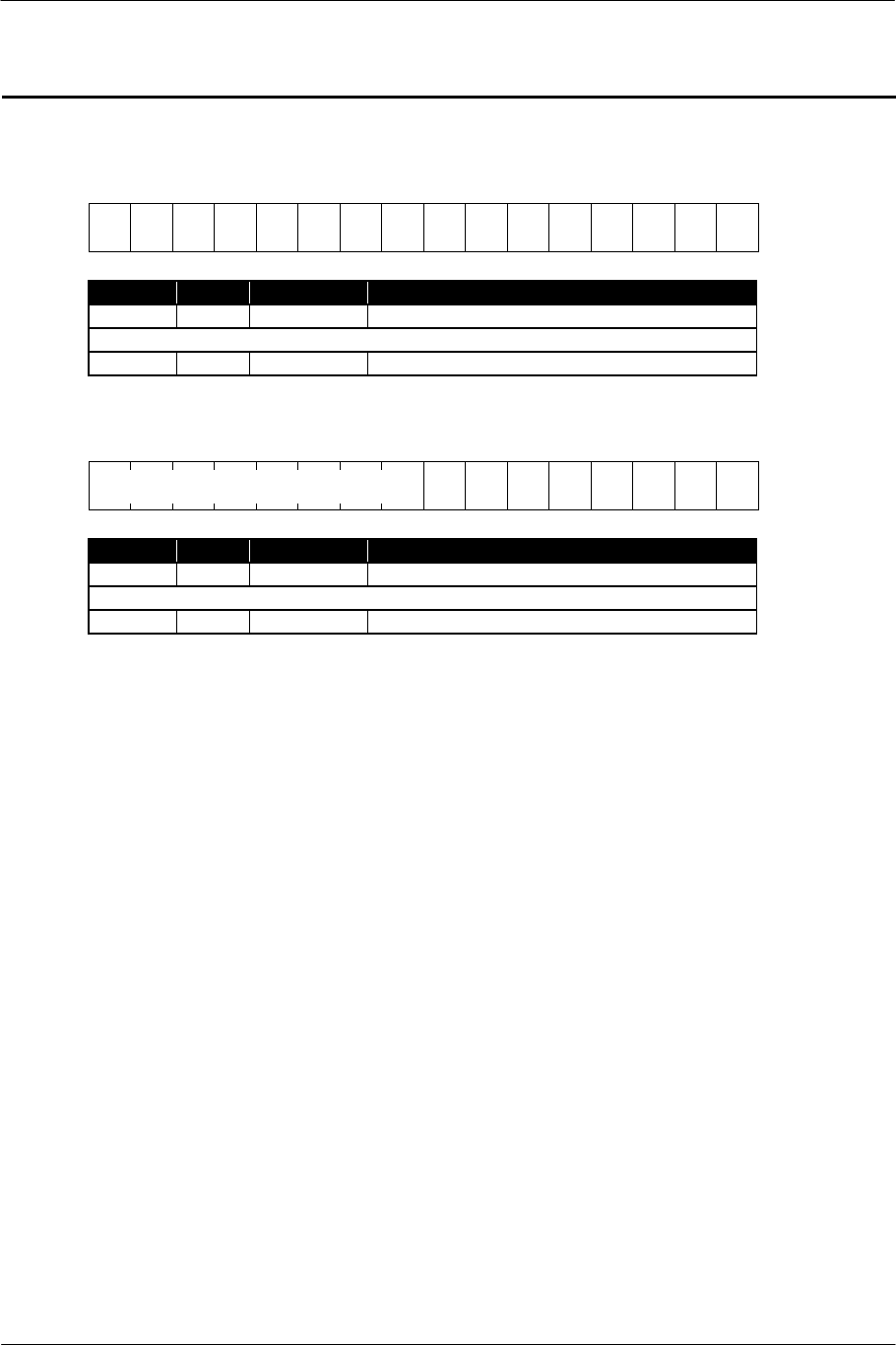
SCE CONFIDENTIAL SPU2 Overview Version 6.0
© SCEI
-54-
KOF0 / KOF1 : Key-off specification
KOF0
15 12 8 4 0
V
15
V
14
V
13
V
12
V
11
V
10
V
9
V
8
V
7
V
6
V
5
V
4
V
3
V
2
V
1
V
0
Name Pos. Format Contents
V0 0 int 0:1:0 Key-off switch of Voice0
(Omitted)
V15 15 int 0:1:0 Key-off switch of Voice15
KOF1
15 12 8 4 0
V
23
V
22
V
21
V
20
V
19
V
18
V
17
V
16
Name Pos. Format Contents
V16 0 int 0:1:0 Key-off switch of Voice16
(Omitted)
V23 7 int 0:1:0 Key-off switch of Voice23
Description
These registers specify key-off (end of sound generation) of each voice. When writing these registers, the
envelope of the voice, which corresponds to the bit set to 1 among the written values, goes to the release
phase.
Notes
Do not write to any bits of the same register (KOF0 or KOF1) twice within 2 Ts. The period of time
between commands may not be sufficient for the commands to execute properly.
Do not specify key-on and key-off of the same voice within 2 Ts. If specified, the voice which actually starts
/ ends sound generation is indeterminate.
(
reserved
)
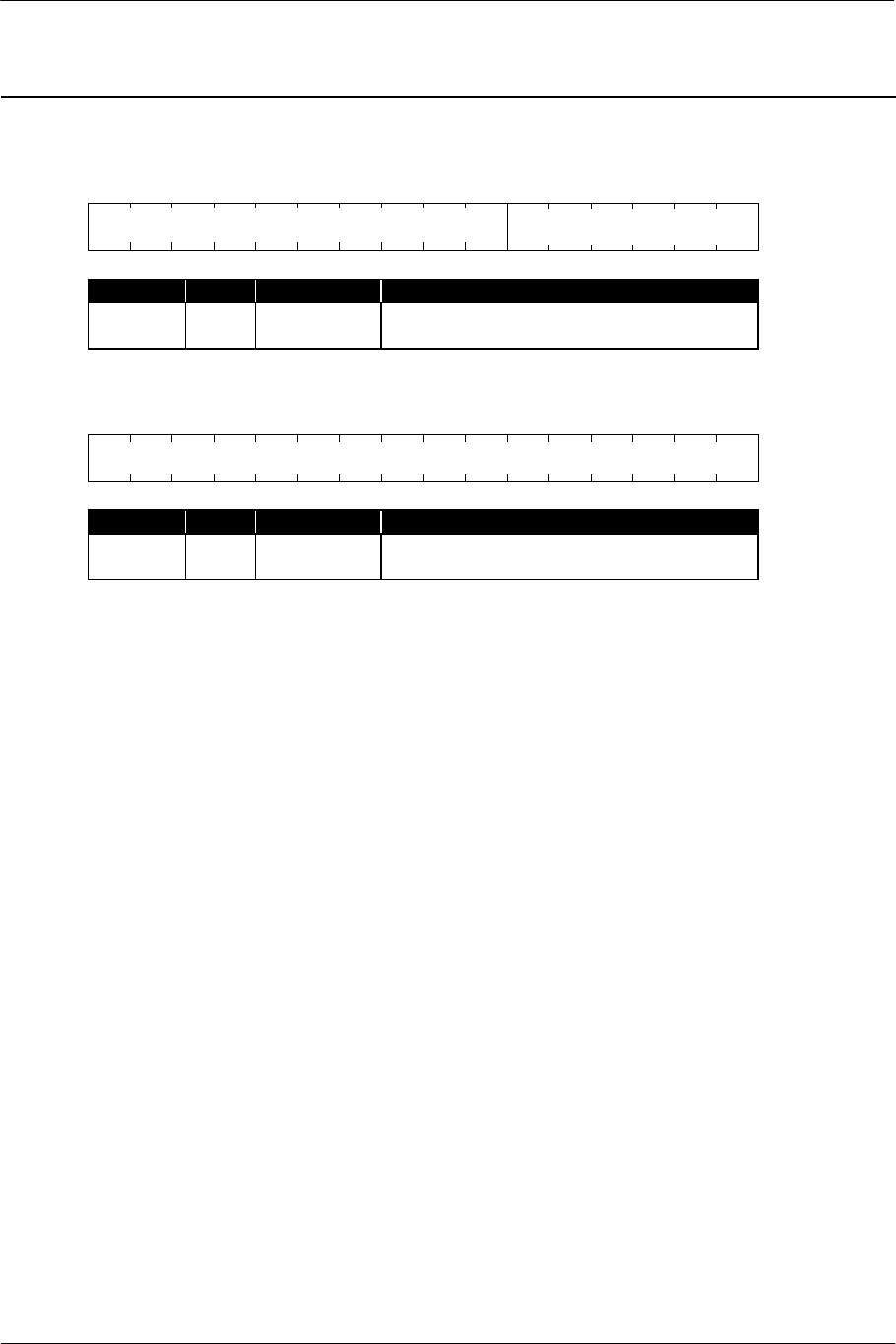
SCE CONFIDENTIAL SPU2 Overview Version 6.0
© SCEI
-55-
TSAH / TSAL : Transfer start address
TSAH
15 12 8 4 0
Name Pos. Format Contents
ADDRH 5:0 int 0:6:0 The starting address of the transfer area in the
local memory (upper 6 bits)
TSAL
15 12 8 4 0
Name Pos. Format Contents
ADDRL 15:0 int 0:16:0 The starting address of the transfer area in the
local memory (lower 16 bits)
Description
These registers specify the starting address in the local memory area, which becomes the source/destination
in DMA read transfer, DMA write transfer, Auto DMA read transfer and single write transfer.
In the SSAL, which specifies the starting address of the waveform data (lower 16 bits) to the voice, the lower
3 bits must be specified to 0 when transferring the waveform data to the local memory. Therefore, in the
case of the TSAL, it is also necessary to transfer data to the address whose lower 3 bits are set to 0.
Notes
The value is invariant regardless of the transfer execution status.
If the value is changed during data transfer, operation and transferred data become indeterminate.
ADDRH
(reserved)
ADDRL
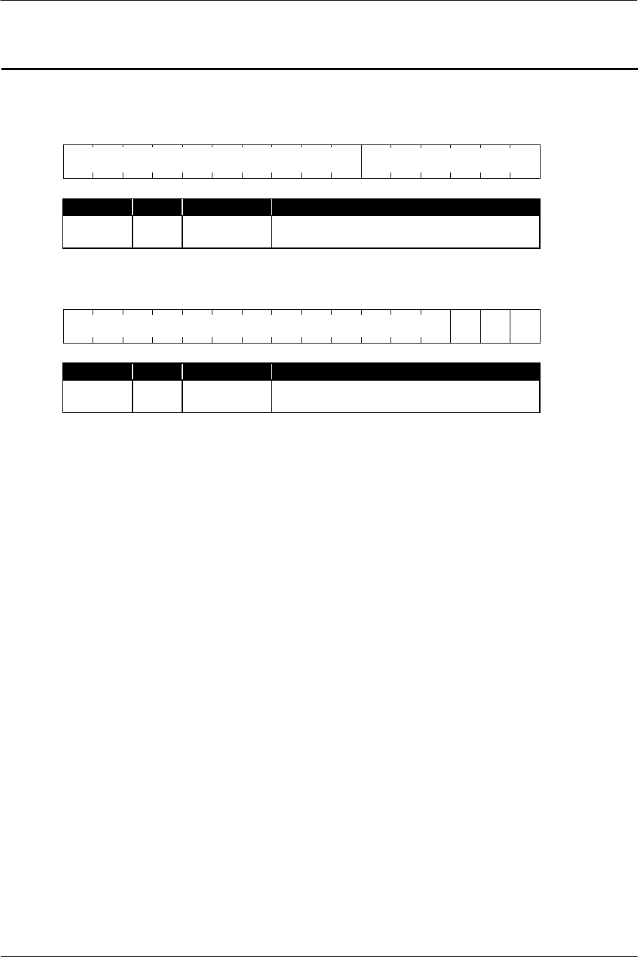
SCE CONFIDENTIAL SPU2 Overview Version 6.0
© SCEI
-56-
SSAH / SSAL : Starting address of waveform data
SSAH
15 12 8 4 0
Name Pos. Format Contents
ADDRH 5:0 int 0:6:0 Starting address of waveform data (upper 6
bits)
SSAL
15 12 8 4 0
0 0 0
Name Pos. Format Contents
ADDRL 15:0 int 0:16:0 Starting address of waveform data (lower 16
bits; 0 is specified to lower 3 bits)
Description
These registers specify the starting address of the waveform data, which becomes the sound source of each
voice.
ADDRH
(reserved)
ADDRL
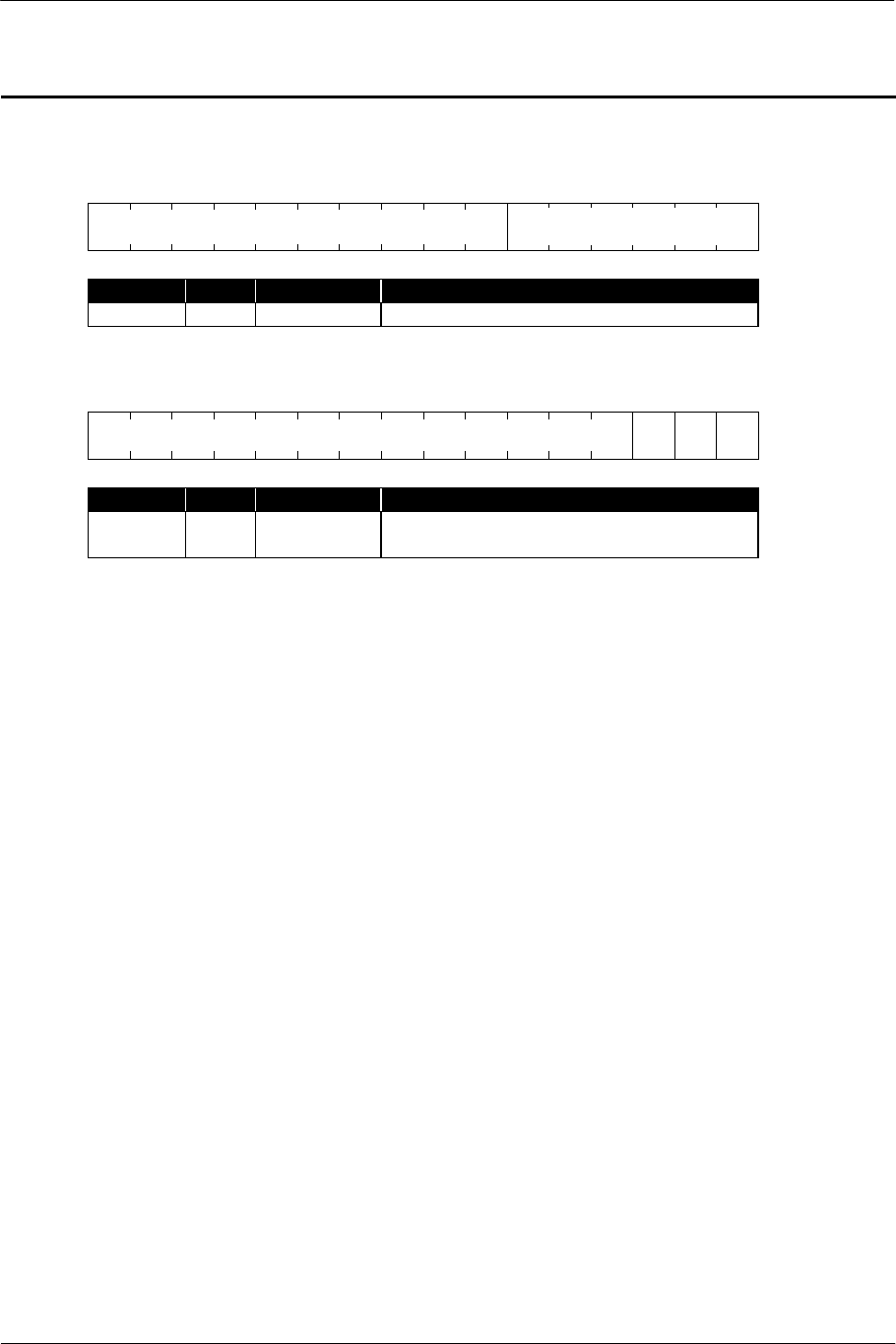
SCE CONFIDENTIAL SPU2 Overview Version 6.0
© SCEI
-57-
LSAXH / LSAXL : Address of loop point
LSAXH
15 12 8 4 0
Name Pos. Format Contents
ADDRH 5:0 int 0:6:0 Loop point address (upper 6 bits)
LSAXL
15 12 8 4 0
0 0 0
Name Pos. Format Contents
ADDRL 15:0 int 0:16:0 Loop point address (lower 16 bits; when
writing, 0 is specified to lower 3 bits)
Description
These registers show the starting address of the block specified as a loop point (the block whose
LOOP/START bit of the header is set to 1) in the waveform data. These are set when the loop point block
is passed through with the advance of sound generation.
The loop point can be set or changed by writing the address of an appropriate block header to this register
during sound generation (4 Ts after the key-on). (Rewriting within 4 Ts is disregarded.) In this case, the
loop point specification of the waveform data is disregarded temporarily until the next time the voice is
keyed on.
ADDRH
(reserved)
ADDRL

SCE CONFIDENTIAL SPU2 Overview Version 6.0
© SCEI
-58-
NAXH / NAXL : Address of waveform data to be read next
NAXH
15 12 8 4 0
Name Pos. Format Contents
ADDRH 5:0 int 0:6:0 Address of the waveform data to be read next
(upper 6 bits)
NAXL
15 12 8 4 0
Name Pos. Format Contents
ADDRL 15:0 int 0:16:0 Address of the waveform data to be read next
(lower 16 bits)
Description
These registers show the address of the waveform data to be read next. They are updated automatically with
the advance of sound generation.
ADDRH
(
reserved
)
ADDRL

SCE CONFIDENTIAL SPU2 Overview Version 6.0
© SCEI
-59-
ESAH / ESAL : Starting address in the work area for effect processing
ESAH
15 12 8 4 0
Name Pos. Format Contents
ADDRH 5:0 int 0:6:0 Starting address in the work area for effect
(upper 6 bits)
ESAL
15 12 8 4 0
Name Pos. Format Contents
ADDRL 15:0 int 0:16:0 Starting address in the work area for effect
(lower 16 bits)
Description
These registers specify the starting address in the work area to be used for digital effect processing.
ADDRH
(
reserved
)
ADDRL

SCE CONFIDENTIAL SPU2 Overview Version 6.0
© SCEI
-60-
EEAH : End address in the work area for effect processing
EEAH
15 12 8 4 0
Name Pos. Format Contents
ADDRH 5:0 int 0:6:0 End address in the work area for effect
processing (upper 6 bits)
Description
This register specifies the end address in the work area to be used for digital effect processing. Unlike other
addressing registers, this register, which specifies the upper 6 bits only, is not paired with a register, which
specifies the lower 16 bits. Because of this, the end address in the work area can only be specified on the
64K short-word (128 KB) boundary.
ADDRH
(reserved)
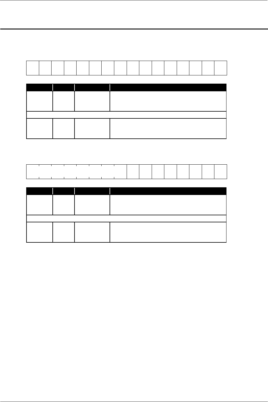
SCE CONFIDENTIAL SPU2 Overview Version 6.0
© SCEI
-61-
ENDX0 / ENDX1 : Endpoint passing flag
ENDX0
15 12 8 4 0
V
15
V
14
V
13
V
12
V
11
V
10
V
9
V
8
V
7
V
6
V
5
V
4
V
3
V
2
V
1
V
0
Name Pos. Format Contents
V0 0 int 0:1:0 Endpoint passing flag for Voice0
0 Has not been passed.
1 Has been passed.
(Omitted)
V15 15 int 0:1:0 Endpoint passing flag for Voice15
0 Has not been passed.
1 Has been passed.
ENDX1
15 12 8 4 0
V
23
V
22
V
21
V
20
V
19
V
18
V
17
V
16
Name Pos. Format Contents
V16 0 int 0:1:0 Endpoint passing flag for Voice16
0 Has not been passed.
1 Has been passsed.
(Omitted)
V23 7 int 0:1:0 Endpoint passing flag for Voice23
0 Has not been passed.
1 Has been passed.
Description
These registers show whether or not the endpoint block has been reached with the advance of sound
generation of each voice.
The bit corresponding to the voice is set to 0 by specifying key-on.
All the bits are cleared to 0 by writing an arbitrary value (including a value other than 0) to these registers.
(reserved)
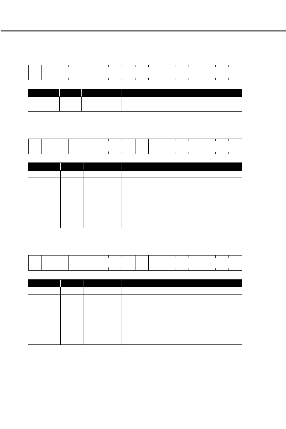
SCE CONFIDENTIAL SPU2 Overview Version 6.0
© SCEI
-62-
MVOLL / MVOLR : Master volume
Constant specification mode (direct mode)
15 12 8 4 0
0
Name Pos. Format Contents
VALUE 14:0 int 1:0:14 Volume value
The phase reverses for a negative value.
Linear increment mode (+lin mode)
15 12 8 4 0
1 0 0 X
0
Name Pos. Format Contents
VALUE 6:0 int 0:7:0 Addition constant per Ts
X 12 int 0:1:0 Polarity specification
0 Normal phase (specifiable when the
current value is positive.)
Linear increment to +1.0
1 Reverse phase (specifiable when the
current value is negative.)
Linear decrement to –1.0
Linear decrement mode (-lin mode)
15 12 8 4 0
1 0 1 X
0
Name Pos. Format Contents
VALUE 6:0 int 0:7:0 Subtraction constant per Ts
X 12 int 0:1:0 Polarity specification
0 Normal phase (specifiable when the
current value is positive.)
Linear decrement to 0
1 Reverse phase (specifiable when the
current value is negative.)
Linear increment to 0
VALUE
VALUE
(
reserved
)
VALUE
(
reserved
)
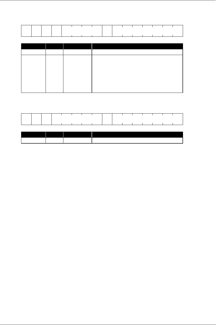
SCE CONFIDENTIAL SPU2 Overview Version 6.0
© SCEI
-63-
Pseudo inverse-exponential increment mode (+exp mode)
15 12 8 4 0
1 1 0 X
0
Name Pos. Format Contents
VALUE 6:0 int 0:7:0 Addition constant per Ts
X 12 int 0:1:0 Polarity specification
0 Normal phase (specifiable when the
current value is positive.)
Increment to +1.0 in a line.
1 Reverse phase (specifiable when the
current value is negative.)
Decrement to –1.0 in a line.
Exponential decrement mode (-exp mode)
15 12 8 4 0
1 1 1 0
Name Pos. Format Contents
VALUE 6:0 int 0:7:0 Multiplication constant
Description
These registers specify the master volume for each core.
The values of the upper three bits specify the pattern of the volume variation with time. When specifying a
mode excluding the constant mode, the master volume value varies with time, because the value
corresponding to the value of the VALUE field is added to, subtracted from or multiplied by the master
volume value per Ts.
For the relationship between the VALUE field value and actual volume duration, refer to "4.1. Rate
Parameter Table".
VALUE
(reserved)
VALUE
(reserved)

SCE CONFIDENTIAL SPU2 Overview Version 6.0
© SCEI
-64-
EVOLL / EVOLR : Return volume of effect
15 12 8 4 0
Name Pos. Format Contents
VALUE 15:0 int 1:0:15 Return volume of effect
The phase reverses for a negative value.
Description
These registers specify the volume when mixing the output from digital effect processing with the Dry
L/Dry R channel.
VALUE

SCE CONFIDENTIAL SPU2 Overview Version 6.0
© SCEI
-65-
AVOLL / AVOLR : Volume for external input
15 12 8 4 0
Name Pos. Format Contents
VALUE 15:0 int 1:0:15 Volume for external input
The phase reverses for a negative value.
Description
These registers specify the volume for the external input.
They are disabled in CORE0.
VALUE

SCE CONFIDENTIAL SPU2 Overview Version 6.0
© SCEI
-66-
BVOLL / BVOLR : Volume for sound data input
15 12 8 4 0
Name Pos. Format Contents
VALUE 15:0 int 1:0:15 Volume for sound data input
The phase reverses for a negative value.
Description
These registers specify the volume for sound data input.
VALUE

SCE CONFIDENTIAL SPU2 Overview Version 6.0
© SCEI
-67-
MVOLXL / MVOLXR : Current value of master volume
15 12 8 4 0
Name Pos. Format Contents
VALUE 15:0 int 1:0:15 Current value of master volume
Description
These registers indicate the current value of the master volume.
When MVOL is in a mode other than constant specification mode, the value varies per Ts according to the
volume variation.
VALUE

SCE CONFIDENTIAL SPU2 Overview Version 6.0
© SCEI
-68-
(This page is left blank intentionally)

SCE CONFIDENTIAL SPU2 Overview Version 6.0
© SCEI
-69-
4. Appendix

SCE CONFIDENTIAL SPU2 Overview Version 6.0
© SCEI
-70-
4.1. Rate Parameter Table
The following tables show the volume variation rate for values of the envelope rate/level parameters (AR, DR,
SL, SR and RR) and the parameters to specify volume variation with time. The variation rate is shown with the
time required for the volume to vary from 0 to 1 (1 to 0, or 1 to 0.1). For SL, the variation rate is shown with
level.

SCE CONFIDENTIAL SPU2 Overview Version 6.0
© SCEI
-71-
4.1.1. +Lin Mode
The variation is shown in linear increment for normal phase and in linear decrement for reverse phase.
Set Value 0 -> 1 Time
000 0000 0.05 (msec)
000 0001 0.06
000 0010 0.07
000 0011 0.09
000 0100 0.10
000 0101 0.12
000 0110 0.15
000 0111 0.18
000 1000 0.21
000 1001 0.24
000 1010 0.29
000 1011 0.36
000 1100 0.41
000 1101 0.48
000 1110 0.58
000 1111 0.73
001 0000 0.83
001 0001 0.97
001 0010 1.2
001 0011 1.5
001 0100 1.7
001 0101 1.9
001 0110 2.3
001 0111 2.9
001 1000 3.3
001 1001 3.9
001 1010 4.6
001 1011 5.8
001 1100 6.6
001 1101 7.7
001 1110 9.3
001 1111 12
010 0000 13
010 0001 15
010 0010 19
010 0011 23
010 0100 27
010 0101 31
010 0110 37
Set Value 0 -> 1 Time
010 0111 46 (msec)
010 1000 53
010 1001 62
010 1010 74
010 1011 93
010 1100 0.11 (sec)
010 1101 0.12
010 1110 0.15
010 1111 0.19
011 0000 0.21
011 0001 0.25
011 0010 0.30
011 0011 0.37
011 0100 0.42
011 0101 0.50
011 0110 0.59
011 0111 0.74
011 1000 0.85
011 1001 0.99
011 1010 1.2
011 1011 1.5
011 1100 1.7
011 1101 2.0
011 1110 2.4
011 1111 3.0
100 0000 3.4
100 0001 4.0
100 0010 4.8
100 0011 5.9
100 0100 6.8
100 0101 7.9
100 0110 9.5
100 0111 12
100 1000 14
100 1001 16
100 1010 19
100 1011 24
100 1100 27
100 1101 32
Set Value 0 -> 1 Time
100 1110 38 (sec)
100 1111 48
101 0000 54
101 0001 63
101 0010 76
101 0011 95
101 0100 109
101 0101 127
101 0110 152
101 0111 190
101 1000 218
101 1001 254
101 1010 304
101 1011 380
101 1100 436
101 1101 508
101 1110 608
101 1111 760
110 0000 872
110 0001 1016
110 0010 1216
110 0011 1520
110 0100 1744
110 0101 2032
110 0110 2432
110 0111 3040
110 1000 3488
110 1001 4064
110 1010 4864
110 1011 6080
110 1100
:
111 1110
(reserved)
111 1111 infinity

SCE CONFIDENTIAL SPU2 Overview Version 6.0
© SCEI
-72-
4.1.2. –Lin Mode
The variation is shown in linear decrement for normal phase and in linear increment for reverse phase.
-Lin Value 1 –> 0 Time
000 0000 0.04 (msec)
000 0001 0.05
000 0010 0.06
000 0011 0.07
000 0100 0.09
000 0101 0.10
000 0110 0.12
000 0111 0.15
000 1000 0.18
000 1001 0.21
000 1010 0.24
000 1011 0.29
000 1100 0.36
000 1101 0.41
000 1110 0.48
000 1111 0.58
001 0000 0.73
001 0001 0.83
001 0010 0.97
001 0011 1.2
001 0100 1.5
001 0101 1.7
001 0110 1.9
001 0111 2.3
001 1000 2.9
001 1001 3.3
001 1010 3.9
001 1011 4.6
001 1100 5.8
001 1101 6.6
001 1110 7.7
001 1111 9.3
010 0000 12
010 0001 13
010 0010 15
010 0011 19
010 0100 23
010 0101 27
010 0110 31
-Lin Value 1 –> 0 Time
010 0111 37 (msec)
010 1000 46
010 1001 53
010 1010 62
010 1011 74
010 1100 93
010 1101 0.11 (sec)
010 1110 0.12
010 1111 0.15
011 0000 0.19
011 0001 0.21
011 0010 0.25
011 0011 0.30
011 0100 0.37
011 0101 0.42
011 0110 0.50
011 0111 0.59
011 1000 0.74
011 1001 0.85
011 1010 0.99
011 1011 1.2
011 1100 1.5
011 1101 1.7
011 1110 2.0
011 1111 2.4
100 0000 3.0
100 0001 3.4
100 0010 4.0
100 0011 4.8
100 0100 5.9
100 0101 6.8
100 0110 7.9
100 0111 9.5
100 1000 12
100 1001 14
100 1010 16
100 1011 19
100 1100 24
100 1101 27
-Lin Value 1 –> 0 Time
100 1110 32 (sec)
100 1111 38
101 0000 48
101 0001 54
101 0010 63
101 0011 76
101 0100 95
101 0101 109
101 0110 127
101 0111 152
101 1000 190
101 1001 218
101 1010 254
101 1011 304
101 1100 380
101 1101 436
101 1110 508
101 1111 608
110 0000 760
110 0001 872
110 0010 1016
110 0011 1216
110 0100 1520
110 0101 1744
110 0110 2032
110 0111 2432
110 1000 3040
110 1001 3488
110 1010 4064
110 1011 4864
110 1100
:
111 1110
(reserved)
111 1111 infinity

SCE CONFIDENTIAL SPU2 Overview Version 6.0
© SCEI
-73-
4.1.3. +Exp Mode (Normal phase)
Pseudo Inverse-Exponential Increment Mode
+Exp Set
Value
1 –> 0 Time
000 0000 0.09 (msec)
000 0001 0.11
000 0010 0.13
000 0011 0.16
000 0100 0.18
000 0101 0.21
000 0110 0.25
000 0111 0.32
000 1000 0.36
000 1001 0.42
000 1010 0.51
000 1011 0.64
000 1100 0.73
000 1101 0.85
000 1110 1.0
000 1111 1.3
001 0000 1.5
001 0001 1.7
001 0010 2.0
001 0011 2.5
001 0100 2.9
001 0101 3.4
001 0110 4.1
001 0111 5.1
001 1000 5.8
001 1001 6.8
001 1010 8.1
001 1011 10
001 1100 12
001 1101 14
001 1110 16
001 1111 20
010 0000 23
010 0001 27
010 0010 33
010 0011 41
+Exp Set
Value
1 –> 0 Time
010 0100 46 (msec)
010 0101 54
010 0110 65
010 0111 81
010 1000 93
010 1001 0.11 (sec)
010 1010 0.13
010 1011 0.16
010 1100 0.19
010 1101 0.22
010 1110 0.26
010 1111 0.33
011 0000 0.37
011 0001 0.43
011 0010 0.52
011 0011 0.65
011 0100 0.74
011 0101 0.87
011 0110 1.0
011 0111 1.3
011 1000 1.5
011 1001 1.7
011 1010 2.1
011 1011 2.6
011 1100 3.0
011 1101 3.5
011 1110 4.2
011 1111 5.2
100 0000 5.9
100 0001 6.9
100 0010 8.3
100 0011 10
100 0100 12
100 0101 14
100 0110 17
100 0111 21
+Exp Set
Value
1 –> 0 Time
100 1000 24 (sec)
100 1001 28
100 1010 33
100 1011 42
100 1100 48
100 1101 55
100 1110 67
100 1111 83
101 0000 95
101 0001 111
101 0010 133
101 0011 166
101 0100 190
101 0101 222
101 0110 266
101 0111 333
101 1000 380
101 1001 444
101 1010 532
101 1011 666
101 1100 760
101 1101 888
101 1110 1064
101 1111 1332
110 0000 1520
110 0001 1776
110 0010 2128
110 0011 2664
110 1100
:
111 1110
(reserved)
111 1111 infinity

SCE CONFIDENTIAL SPU2 Overview Version 6.0
© SCEI
-74-
4.1.4. +Exp Mode (Reverse phase)
Pseudo Inverse-Exponential Mode with Negative Volume Value
+Exp Set
Value
1 -> 0 Time
000 0000 0.08 (msec)
000 0001 0.09
000 0010 0.11
000 0011 0.13
000 0100 0.16
000 0101 0.18
000 0110 0.21
000 0111 0.25
000 1000 0.32
000 1001 0.36
000 1010 0.42
000 1011 0.51
000 1100 0.64
000 1101 0.73
000 1110 0.85
000 1111 1.0
001 0000 1.3
001 0001 1.5
001 0010 1.7
001 0011 2.0
001 0100 2.5
001 0101 2.9
001 0110 3.4
001 0111 4.1
001 1000 5.1
001 1001 5.8
001 1010 6.8
001 1011 8.1
001 1100 10
001 1101 12
001 1110 14
001 1111 16
010 0000 20
010 0001 23
010 0010 27
010 0011 33
+Exp Set
Value
1 -> 0 Time
010 0100 41 (msec)
010 0101 46
010 0110 54
010 0111 64
010 1000 81
010 1001 93
010 1010 0.11 (sec)
010 1011 0.13
010 1100 0.16
010 1101 0.19
010 1110 0.22
010 1111 0.26
011 0000 0.33
011 0001 0.37
011 0010 0.43
011 0011 0.52
011 0100 0.65
011 0101 0.74
011 0110 0.87
011 0111 1.0
011 1000 1.3
011 1001 1.5
011 1010 1.7
011 1011 2.1
011 1100 2.6
011 1101 3.0
011 1110 3.5
011 1111 4.2
100 0000 5.2
100 0001 5.9
100 0010 6.9
100 0011 8.3
100 0100 10
100 0101 12
100 0110 14
100 0111 17
+Exp Set
Value
1 -> 0 Time
100 1000 21 (sec)
100 1001 24
100 1010 28
100 1011 33
100 1100 42
100 1101 48
100 1110 55
100 1111 67
101 0000 83
101 0001 95
101 0010 111
101 0011 133
101 0100 166
101 0101 190
101 0110 222
101 0111 266
101 1000 333
101 1001 380
101 1010 444
101 1011 532
101 1100 666
101 1101 760
101 1110 888
101 1111 1064
110 0000 1332
110 0001 1520
110 0010 1776
110 0011 2128
110 1100
:
111 1110
(reserved)
111 1111 infinity

SCE CONFIDENTIAL SPU2 Overview Version 6.0
© SCEI
-75-
4.1.5. –Exp Mode
Exponential Decrement Mode
-Exp Set
Value
1 –> 0.1
Time
000 0000 0.07 (msec)
000 0001 0.09
000 0010 0.11
000 0011 0.14
000 0100 0.18
000 0101 0.21
000 0110 0.25
000 0111 0.31
000 1000 0.39
000 1001 0.45
000 1010 0.53
000 1011 0.64
000 1100 0.81
000 1101 0.93
000 1110 1.1
000 1111 1.3
001 0000 1.6
001 0001 1.9
001 0010 2.2
001 0011 2.6
001 0100 3.3
001 0101 3.8
001 0110 4.4
001 0111 5.3
001 1000 6.7
001 1001 7.6
001 1010 8.9
001 1011 11
001 1100 13
001 1101 15
001 1110 18
001 1111 21
010 0000 27
010 0001 31
010 0010 36
010 0011 43
010 0100 53
010 0101 61
010 0110 71
-Exp Set
Value
1 –> 0.1
Time
010 0111 86 (msec)
010 1000 0.11 (sec)
010 1001 0.12
010 1010 0.14
010 1011 0.17
010 1100 0.21
010 1101 0.24
010 1110 0.29
010 1111 0.34
011 0000 0.43
011 0001 0.49
011 0010 0.57
011 0011 0.68
011 0100 0.86
011 0101 0.98
011 0110 1.1
011 0111 1.4
011 1000 1.7
011 1001 2.0
011 1010 2.3
011 1011 2.7
011 1100 3.4
011 1101 3.9
011 1110 4.6
011 1111 5.5
100 0000 6.8
100 0001 7.8
100 0010 9.1
100 0011 11
100 0100 14
100 0101 16
100 0110 18
100 0111 22
100 1000 27
100 1001 31
100 1010 36
100 1011 44
100 1100 55
100 1101 63
-Exp Set
Value
1 –> 0.1
Time
100 1110 73 (sec)
100 1111 88
101 0000 109
101 0001 125
101 0010 146
101 0011 175
101 0100 219
101 0101 250
101 0110 292
101 0111 350
101 1000 438
101 1001 500
101 1010 584
101 1011 700
101 1100 876
101 1101 1000
101 1110 1168
101 1111 1400
110 0000 1752
110 0001 2000
110 0010 2336
110 0011 2800
110 0100 3504
110 0101 4000
110 0110 4672
110 0111 5600
110 1000 7008
110 1001 8000
110 1010 9344
110 1011 11200
110 1100
:
111 1110
(reserved)
111 1111 infinity

SCE CONFIDENTIAL SPU2 Overview Version 6.0
© SCEI
-76-
4.1.6. Decay Rate (DR)
Exponential Decrement Mode
-Exp Set
Value
1 –> 0.10
Time
0000 0.07 (msec)
0001 0.18
0010 0.39
0011 0.81
0100 1.6
0101 3.3
0110 6.7
0111 13
1000 27
1001 53
1010 0.11 (sec)
1011 0.21
1100 0.43
1101 0.86
1110 1.7
1111 3.4

SCE CONFIDENTIAL SPU2 Overview Version 6.0
© SCEI
-77-
4.1.7. Sustain Level (SL)
Set Value Envelope
Level
0000 1/16
0001 2/16
0010 3/16
0011 4/16
0100 5/16
0101 6/16
0110 7/16
0111 8/16
1000 9/16
1001 10/16
1010 11/16
1011 12/16
1100 13/16
1101 14/16
1110 15/16
1111 1
Note: when the set value is 1111, the Decay section immediately before is processed only for 1 Ts.

SCE CONFIDENTIAL SPU2 Overview Version 6.0
© SCEI
-78-
4.1.8. –Lin Mode for Release Rate (RR)
Linear Decrement Mode
-Lin Set
Value
1 –> 0 Time
0 0000 0.04 (msec)
0 0001 0.09
0 0010 0.18
0 0011 0.36
0 0100 0.73
0 0101 1.5
0 0110 2.9
0 0111 5.8
0 1000 12
0 1001 23
0 1010 46
0 1011 93
0 1100 0.19 (sec)
0 1101 0.37
0 1110 0.74
0 1111 1.5
1 0000 3.0
1 0001 5.9
1 0010 12
1 0011 24
1 0100 48
1 0101 95
1 0110 190
1 0111 380
1 1000 760
1 1001 1520
1 1010 3040
1 1011
:
1 1110
(reserved)
1 1111 infinity

SCE CONFIDENTIAL SPU2 Overview Version 6.0
© SCEI
-79-
4.1.9. –Exp Mode for Release Rate (RR)
Exponential Decrement Mode
-Exp Set
Value
1 –> 0.1
Time
0 0000 0.07 (msec)
0 0001 0.18
0 0010 0.39
0 0011 0.81
0 0100 1.6
0 0101 3.3
0 0110 6.7
0 0111 13
0 1000 27
0 1001 53
0 1010 0.11 (sec)
0 1011 0.21
0 1100 0.43
0 1101 0.86
0 1110 1.7
0 1111 3.4
1 0000 6.8
1 0001 14
1 0010 27
1 0011 55
1 0100 109
1 0101 219
1 0110 438
1 0111 876
1 1000 1752
1 1001 3504
1 1010 7008
1 1011
:
1 1110
(reserved)
1 1111 infinity

SCE CONFIDENTIAL SPU2 Overview Version 6.0
© SCEI
-80-
(This page is left blank intentionally)
