TI BLE HCI Vendor Specific Guide
TI_BLE_Vendor_Specific_HCI_Guide
TI_BLE_Vendor_Specific_HCI_Guide
TI_BLE_Vendor_Specific_HCI_Guide
TI_BLE_Vendor_Specific_HCI_Guide
TI_BLE_Vendor_Specific_HCI_Guide
User Manual: Pdf
Open the PDF directly: View PDF ![]() .
.
Page Count: 195 [warning: Documents this large are best viewed by clicking the View PDF Link!]

TI BLE Vendor Specific
HCI Reference Guide
Version 2.1.0

TI BLE HCI Vendor Specific HCI Guide
Page 2 of 195
Copyright © 2014-2015 Texas Instruments Inc.
TABLE OF CONTENTS
1. PURPOSE .............................................................................................................................................. 8
2. FUNCTIONAL OVERVIEW .............................................................................................................. 8
3. NUMERICAL NOTATION CONVENTIONS .................................................................................. 9
4. DEFINITIONS, ABBREVIATIONS, ACRONYMS........................................................................ 10
5. REFERENCES .................................................................................................................................... 11
6. REVISION HISTORY ....................................................................................................................... 11
7. HCI OVERVIEW ............................................................................................................................... 12
8. SPECIFICATION INTERFACE ....................................................................................................... 12
8.1 HCI INTERFACE PROTOCOL ........................................................................................................... 12
8.1.1 Command Packet .................................................................................................................. 13
8.1.2 Asynchronous Data Packet ................................................................................................... 13
8.1.3 Synchronous Data Packet ..................................................................................................... 14
8.1.4 Event Packet ......................................................................................................................... 14
8.2 HCI COMMAND ............................................................................................................................. 14
8.3 HCI EVENTS .................................................................................................................................. 16
9. VENDOR SPECIFIC INTERFACE ................................................................................................. 17
9.1 VENDOR SPECIFIC COMMANDS ...................................................................................................... 17
9.2 VENDOR SPECIFIC EVENTS ............................................................................................................ 22
9.3 REQUEST AND RESPONSE TUNNELING ........................................................................................... 26
10. HCI EXTENSION VENDOR SPECIFIC COMMANDS ............................................................ 27
10.1 HCI EXTENSION SET RECEIVER GAIN ............................................................................................ 27
10.2 HCI EXTENSION SET TRANSMITTER POWER .................................................................................. 28
10.3 HCI EXTENSION ONE PACKET PER EVENT .................................................................................... 30
10.4 HCI EXTENSION CLOCK DIVIDE ON HALT ..................................................................................... 31
10.5 HCI EXTENSION DECLARE NV USAGE .......................................................................................... 32
10.6 HCI EXTENSION DECRYPT ............................................................................................................. 33
10.7 HCI EXTENSION SET LOCAL SUPPORTED FEATURES ..................................................................... 34
10.8 HCI EXTENSION SET FAST TRANSMIT RESPONSE TIME ................................................................. 35
10.9 HCI EXTENSION MODEM TEST TRANSMIT .................................................................................... 36
10.10 HCI EXTENSION MODEM HOP TEST TRANSMIT ......................................................................... 37
10.11 HCI EXTENSION MODEM TEST RECEIVE ................................................................................... 38
10.12 HCI EXTENSION END MODEM TEST .......................................................................................... 39
10.13 HCI EXTENSION SET BDADDR ................................................................................................ 40
10.14 HCI EXTENSION SET SCA ......................................................................................................... 41
10.15 HCI EXTENSION ENABLE PTM .................................................................................................. 42
10.16 HCI EXTENSION SET FREQUENCY TUNING ................................................................................ 43
10.17 HCI EXTENSION SAVE FREQUENCY TUNING ............................................................................. 44
10.18 HCI EXTENSION SET MAX DTM TRANSMITTER POWER ........................................................... 45
10.19 HCI EXTENSION MAP PM IO PORT ........................................................................................... 47
10.20 HCI EXTENSION DISCONNECT IMMEDIATE ................................................................................ 49
10.21 HCI EXTENSION PACKET ERROR RATE...................................................................................... 50

TI BLE HCI Vendor Specific HCI Guide
Page 3 of 195
Copyright © 2014-2015 Texas Instruments Inc.
10.22 HCI EXTENSION PACKET ERROR RATE BY CHANNEL ............................................................... 51
10.23 HCI EXTENSION EXTEND RF RANGE ......................................................................................... 53
10.24 HCI EXTENSION ADVERTISER EVENT NOTICE ........................................................................... 54
10.25 HCI EXTENSION CONNECTION EVENT NOTICE .......................................................................... 55
10.26 HCI EXTENSION HALT DURING RF ............................................................................................ 56
10.27 HCI EXTENSION SET SLAVE LATENCY OVERRIDE ..................................................................... 57
10.28 HCI EXTENSION BUILD REVISION .............................................................................................. 58
10.29 HCI EXTENSION DELAY SLEEP .................................................................................................. 59
10.30 HCI EXTENSION RESET SYSTEM ................................................................................................ 60
10.31 HCI EXTENSION OVERLAPPED PROCESSING .............................................................................. 61
10.32 HCI EXTENSION NUMBER COMPLETED PACKETS LIMIT ............................................................ 62
10.33 HCI EXTENSION GET CONNECTION INFORMATION .................................................................... 63
11. HCI EXTENSION VENDOR SPECIFIC EVENTS .................................................................... 65
11.1 HCI EXTENSION SET RECEIVER GAIN ............................................................................................ 65
11.2 HCI EXTENSION SET TRANSMITTER POWER .................................................................................. 65
11.3 HCI EXTENSION ONE PACKET PER EVENT .................................................................................... 66
11.4 HCI EXTENSION CLOCK DIVIDE ON HALT ..................................................................................... 66
11.5 HCI EXTENSION DECLARE NV USAGE .......................................................................................... 67
11.6 HCI EXTENSION DECRYPT ............................................................................................................. 67
11.7 HCI EXTENSION SET LOCAL SUPPORTED FEATURES ..................................................................... 68
11.8 HCI EXTENSION SET FAST TRANSMIT RESPONSE TIME ................................................................. 68
11.9 HCI EXTENSION MODEM TEST TRANSMIT .................................................................................... 69
11.10 HCI EXTENSION MODEM HOP TEST TRANSMIT ......................................................................... 69
11.11 HCI EXTENSION MODEM TEST RECEIVE ................................................................................... 70
11.12 HCI EXTENSION END MODEM TEST .......................................................................................... 70
11.13 HCI EXTENSION SET BDADDR ................................................................................................ 71
11.14 HCI EXTENSION SET SCA ......................................................................................................... 71
11.15 HCI EXTENSION ENABLE PTM .................................................................................................. 72
11.16 HCI EXTENSION SET FREQUENCY TUNING ................................................................................ 72
11.17 HCI EXTENSION SAVE FREQUENCY TUNING ............................................................................. 72
11.18 HCI EXTENSION SET MAX DTM TRANSMITTER POWER ........................................................... 73
11.19 HCI EXTENSION MAP PM IO PORT ........................................................................................... 73
11.20 HCI EXTENSION DISCONNECT IMMEDIATE ................................................................................ 74
11.21 HCI EXTENSION PACKET ERROR RATE...................................................................................... 74
11.22 HCI EXTENSION PACKET ERROR RATE BY CHANNEL ............................................................... 75
11.23 HCI EXTENSION EXTEND RF RANGE ......................................................................................... 76
11.24 HCI EXTENSION ADVERTISER EVENT NOTICE ........................................................................... 76
11.25 HCI EXTENSION CONNECTION EVENT NOTICE .......................................................................... 76
11.26 HCI EXTENSION HALT DURING RF ............................................................................................ 77
11.27 HCI EXTENSION SET SLAVE LATENCY OVERRIDE ..................................................................... 77
11.28 HCI EXTENSION BUILD REVISION .............................................................................................. 78
11.29 HCI EXTENSION DELAY SLEEP .................................................................................................. 78
11.30 HCI EXTENSION RESET SYSTEM ................................................................................................ 79
11.31 HCI EXTENSION OVERLAPPED PROCESSING .............................................................................. 80
11.32 HCI EXTENSION NUMBER COMPLETED PACKETS LIMIT ............................................................ 80
11.33 HCI EXTENSION GET CONNECTION INFORMATION .................................................................... 81
12. GAP VENDOR SPECIFIC COMMANDS ................................................................................... 82
12.1 GAP DEVICE INITIALIZATION ......................................................................................................... 82
12.2 GAP CONFIGURE DEVICE ADDRESS .............................................................................................. 83
12.3 GAP DEVICE DISCOVERY REQUEST .............................................................................................. 84
12.4 GAP DEVICE DISCOVERY CANCEL ................................................................................................ 85

TI BLE HCI Vendor Specific HCI Guide
Page 4 of 195
Copyright © 2014-2015 Texas Instruments Inc.
12.5 GAP MAKE DISCOVERABLE .......................................................................................................... 86
12.6 GAP UPDATE ADVERTISING DATA ................................................................................................ 88
12.7 GAP END DISCOVERABLE ............................................................................................................. 89
12.8 GAP ESTABLISH LINK REQUEST .................................................................................................... 89
12.9 GAP TERMINATE LINK REQUEST ................................................................................................... 91
12.10 GAP AUTHENTICATE ................................................................................................................. 92
12.11 GAP UPDATE LINK PARAMETER REQUEST ................................................................................ 95
12.12 GAP PASSKEY UPDATE ............................................................................................................. 97
12.13 GAP SLAVE SECURITY REQUEST ............................................................................................... 98
12.14 GAP SIGNABLE .......................................................................................................................... 99
12.15 GAP BOND .............................................................................................................................. 100
12.16 GAP TERMINATE AUTH ........................................................................................................... 101
12.17 GAP SET PARAMETER ............................................................................................................. 102
12.18 GAP GET PARAMETER ............................................................................................................ 106
12.19 GAP RESOLVE PRIVATE ADDRESS........................................................................................... 107
12.20 GAP SET ADVERTISEMENT TOKEN .......................................................................................... 107
12.21 GAP REMOVE ADVERTISEMENT TOKEN .................................................................................. 109
12.22 GAP UPDATE ADVERTISEMENT TOKENS ................................................................................. 111
12.22.1 GAP Bond Set Parameter ............................................................................................... 111
12.22.2 GAP Bond Get Parameter ............................................................................................... 113
13. GAP VENDOR SPECIFIC EVENTS .......................................................................................... 115
13.1 GAP DEVICE INIT DONE .............................................................................................................. 115
13.2 GAP DEVICE DISCOVERY ............................................................................................................ 116
13.3 GAP ADVERT DATA UPDATE DONE ............................................................................................ 117
13.4 GAP MAKE DISCOVERABLE DONE .............................................................................................. 117
13.5 GAP END DISCOVERABLE DONE ................................................................................................. 118
13.6 GAP LINK ESTABLISHED ............................................................................................................. 118
13.7 GAP LINK TERMINATED .............................................................................................................. 120
13.8 GAP LINK PARMETER UPDATE .................................................................................................... 121
13.9 GAP RANDOM ADDRESS CHANGED ............................................................................................ 122
13.10 GAP SIGNATURE UPDATED ..................................................................................................... 123
13.11 GAP AUTHENTICATION COMPLETE ......................................................................................... 124
13.12 GAP PASSKEY NEEDED ........................................................................................................... 127
13.13 GAP SLAVE REQUESTED SECURITY ......................................................................................... 128
13.14 GAP DEVICE INFORMATION .................................................................................................... 129
13.15 GAP BOND COMPLETE ............................................................................................................ 130
13.16 GAP PAIRING REQUESTED ....................................................................................................... 131
13.17 COMMAND STATUS .................................................................................................................. 133
14. UTIL VENDOR SPECIFIC COMMANDS ................................................................................ 134
14.1 UTIL NV READ COMMAND ......................................................................................................... 134
14.2 UTIL NV WRITE COMMAND ....................................................................................................... 136
14.3 UTIL FORCE BOOT COMMAND.................................................................................................... 137
14.4 UTIL BUILD REVISION COMMAND .............................................................................................. 137
15. L2CAP VENDOR SPECIFIC COMMANDS ............................................................................. 140
15.1 L2CAP_DATA (0XFCF0) ............................................................................................................ 140
15.2 L2CAP_REGISTERPSM (0XFCF1) ............................................................................................... 141
15.3 L2CAP_DEREGISTERPSM (0XFCF2) ........................................................................................... 143
15.4 L2CAP_PSMINFO (0XFCF3) ....................................................................................................... 143
15.5 L2CAP_PSMCHANNELS (0XFCF4) ............................................................................................. 145
15.6 L2CAP_CHANNELINFO (0XFCF5) .............................................................................................. 145

TI BLE HCI Vendor Specific HCI Guide
Page 5 of 195
Copyright © 2014-2015 Texas Instruments Inc.
15.7 L2CAP_CONNECTREQ (0XFC94) ............................................................................................... 148
15.8 L2CAP_CONNECTRSP (0XFC95) ................................................................................................ 148
15.9 L2CAP_DISCONNECTREQ (0XFC86) .......................................................................................... 150
15.10 L2CAP_FLOWCTRLCREDIT (0XFC96) .................................................................................... 150
15.11 L2CAP_CONNPARAMUPDATEREQ (0XFC92) ......................................................................... 151
16. L2CAP VENDOR SPECIFIC EVENTS ..................................................................................... 154
16.1 L2CAP_CMDREJCT (0X0481) ..................................................................................................... 154
16.2 L2CAP_CONNPARAMUPDATERSP (0X0493) .............................................................................. 154
16.3 L2CAP_CONNECTREQ (0X0494) ................................................................................................ 155
16.4 L2CAP_CHANNELESTABLISHED (0X04E0) ................................................................................. 156
16.5 L2CAP_CHANNELTERMINATED (0X04E1) ................................................................................. 157
16.6 L2CAP_OUTOFCREDIT (0X04E2) ............................................................................................... 158
16.7 L2CAP_PEERCREDITTHRESHOLD (0X04E3) ............................................................................... 159
16.8 L2CAP_SENDSDUDONE (0X04E4) ............................................................................................. 159
16.9 L2CAP_DATA (0X04F0) ............................................................................................................. 160
17. ATT VENDOR SPECIFIC COMMANDS AND EVENTS ....................................................... 162
17.1 ATT VENDOR SPECIFIC COMMANDS ........................................................................................... 162
17.2 ATT VENDOR SPECIFIC EVENTS .................................................................................................. 163
17.3 ATT_ERRORRSP (COMMAND = 0XFD01, EVENT = 0X0501) ...................................................... 163
17.4 ATT_EXCHANGEMTUREQ (COMMAND = 0XFD02, EVENT = 0X0502) ...................................... 164
17.5 ATT_EXCHANGEMTURSP (COMMAND = 0XFD03, EVENT = 0X0503) ....................................... 165
17.6 ATT_FINDINFOREQ (COMMAND = 0XFD04, EVENT = 0X0504) ................................................. 165
17.7 ATT_FINDINFORSP (COMMAND = 0XFD05, EVENT = 0X0505) .................................................. 165
17.8 ATT_FINDBYTYPEVALUEREQ (COMMAND = 0XFD06, EVENT = 0X0506) ................................ 166
17.9 ATT_FINDBYTYPEVALUERSP (COMMAND = 0XFD07, EVENT = 0X0507) ................................. 167
17.10 ATT_READBYTYPEREQ (COMMAND = 0XFD08, EVENT = 0X0508) ...................................... 167
17.11 ATT_READBYTYPERSP (COMMAND = 0XFD09, EVENT = 0X0509) ....................................... 168
17.12 ATT_READREQ (COMMAND = 0XFD0A, EVENT = 0X050A) .................................................. 169
17.13 ATT_READRSP (COMMAND = 0XFD0B, EVENT = 0X050B) ................................................... 169
17.14 ATT_READBLOBREQ (COMMAND = 0XFD0C, EVENT = 0X050C) ......................................... 169
17.15 ATT_READBLOBRSP (COMMAND = 0XFD0D) ....................................................................... 170
17.16 ATT_READMULTIREQ (COMMAND = 0XFD0E, EVENT = 0X050E) ........................................ 170
17.17 ATT_READMULTIRSP (COMMAND = 0XFD0F, EVENT = 0X050F) ......................................... 171
17.18 ATT_READBYGRPTYPEREQ (COMMAND = 0XFD10, EVENT = 0X0510) ............................... 171
17.19 ATT_READBYGRPTYPERSP (COMMAND = 0XFD11, EVENT = 0X0511) ................................ 172
17.20 ATT_WRITEREQ (COMMAND = 0XFD12, EVENT = 0X0512) .................................................. 172
17.21 ATT_WRITERSP (COMMAND = 0XFD13, EVENT = 0X0513) ................................................... 173
17.22 ATT_PREPAREWRITEREQ (COMMAND = 0XFD16, EVENT = 0X0516) .................................... 173
17.23 ATT_PREPAREWRITERSP (COMMAND = 0XFD17, EVENT = 0X0517) .................................... 174
17.24 ATT_EXECUTEWRITEREQ (COMMAND = 0XFD18, EVENT = 0X0518) ................................... 175
17.25 ATT_EXECUTEWRITERSP (COMMAND = 0XFD19, EVENT = 0X0519) .................................... 175
17.26 ATT_HANDLEVALUENOTI (COMMAND = 0XFD1B, EVENT = 0X051B) .................................. 175
17.27 ATT_HANDLEVALUEIND (COMMAND = 0XFD1D, EVENT = 0X051D) ................................... 176
17.28 ATT_HANDLEVALUECFM (COMMAND = 0XFD1E, EVENT = 0X051E) ................................... 176
17.29 ATT_FLOWCTRLVIOLATEDEVT (0X057E) .............................................................................. 177
17.30 ATT_MTUUPDATEDEVT (0X057F) ......................................................................................... 177
18. GATT VENDOR SPECIFIC COMMANDS .............................................................................. 178
18.1 GATT_EXCHANGEMTU (0XFD82) ............................................................................................ 178
18.2 GATT_DISCALLPRIMARYSERVICES (0XFD90) .......................................................................... 179
18.3 GATT_DISCPRIMARYSERVICEBYUUID (0XFD86) .................................................................... 179

TI BLE HCI Vendor Specific HCI Guide
Page 6 of 195
Copyright © 2014-2015 Texas Instruments Inc.
18.4 GATT_FINDINCLUDEDSERVICES (0XFDB0) ............................................................................... 179
18.5 GATT_DISCALLCHARS (0XFDB2) ............................................................................................. 180
18.6 GATT_DISCCHARSBYUUID (0XFD88) ..................................................................................... 181
18.7 GATT_DISCALLCHARDESCS (0XFD84) ..................................................................................... 181
18.8 GATT_READCHARVALUE (0XFD8A) ........................................................................................ 182
18.9 GATT_READUSINGCHARUUID (0XFDB4) ................................................................................ 182
18.10 GATT_READLONGCHARVALUE (0XFD8C) ........................................................................... 182
18.11 GATT_READMULTICHARVALUES (0XFD8E) ......................................................................... 183
18.12 GATT_WRITENORSP (0XFDB6) ............................................................................................ 183
18.13 GATT_SIGNEDWRITENORSP (0XFDB8) ................................................................................ 184
18.14 GATT_WRITECHARVALUE (0XFD92) .................................................................................... 184
18.15 GATT_WRITELONGCHARVALUE (0XFD96) .......................................................................... 185
18.16 GATT_RELIABLEWRITES (0XFDBA) ..................................................................................... 186
18.17 GATT_READCHARDESC (0XFDBC) ...................................................................................... 186
18.18 GATT_READLONGCHARDESC (0XFDBE) ............................................................................. 187
18.19 GATT_WRITECHARDESC (0XFDC0)...................................................................................... 187
18.20 GATT_WRITELONGCHARDESC (0XFDC2) ............................................................................ 188
18.21 GATT_NOTIFICATION (0XFD9B) ............................................................................................ 188
18.22 GATT_INDICATION (0XFD9D) ............................................................................................... 189
18.23 GATT_ADDSERVICE (0XFDFC) ............................................................................................. 189
18.24 GATT_DELSERVICE (0XFDFD).............................................................................................. 190
18.25 GATT_ADDATTRIBUTE (0XFDFE) ......................................................................................... 190
19. GATT VENDOR SPECIFIC EVENTS ....................................................................................... 192
19.1 GATT_CLIENTCHARCFGUPDATED (0X0580) ............................................................................. 192
20. HOST ERROR CODES ............................................................................................................... 194

TI BLE HCI Vendor Specific HCI Guide
Page 7 of 195
Copyright © 2014-2015 Texas Instruments Inc.
TABLE OF FIGURES
Figure 1: Logical Organization of Application and BLE Stack ...................................................................... 8
Figure 2: Single Device Configuration ........................................................................................................... 8
Figure 3: Dual Device Configuration .............................................................................................................. 9
Figure 4: Network Processor Configuration with HCI .................................................................................... 9
Figure 5: Command Packet ........................................................................................................................... 13
Figure 6: Asynchronous Data Packet ............................................................................................................ 13
Figure 7: Event Packet .................................................................................................................................. 14
Figure 8: Request/Response with Server Database in BLE Stack ................................................................. 26
Figure 9: Request/Response with Server Database not in BLE Stack ........................................................... 26
TABLE OF TABLES
Table 1: HCI Packet Types ........................................................................................................................... 13
Table 2: BLE Commands .............................................................................................................................. 16
Table 3: BLE Events ..................................................................................................................................... 17
Table 4: Command Opcode Subgroups ........................................................................................................ 18
Table 5: Vendor Specific Commands ........................................................................................................... 21
Table 6: Event Opcode Group ...................................................................................................................... 22
Table 7: Vendor Specific Events .................................................................................................................. 25
Table 8: List of Possible Host Error Codes................................................................................................. 195
TI BLE HCI Vendor Specific HCI Guide
Page 8 of 195
Copyright © 2014-2015 Texas Instruments Inc.
1. Purpose
The purpose of this document is to describe the Texas Instruments Inc. (TI) vendor specific
Host Controller Interface (HCI) for Bluetooth® low energy (BLE). This document is intended for
customer product software engineers and field application engineers working with the TI BLE
stack software.
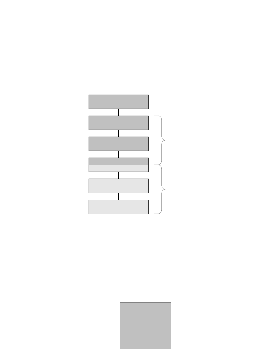
2. Functional Overview
In BLE, there is a logical distinction between the Host software (often referred to as the higher
layer stack) and the Controller software (please see Figure 1).
Figure 1: Logical Organization of Application and BLE Stack
These components can either exist on the same device (single-device configuration), or be
placed on separate devices (dual-device configuration) utilizing a Host Controller Interface (HCI)
for communication (see section 7 for more detail). In the single-device configuration, there is
obviously only one device, and the application software would execute on top of the BLE profiles
and stack (please see Figure 2).
Figure 2: Single Device Configuration
BLE Profiles/Protocols
BLE L2CAP
LL
PHY
HCI
BLE Host
BLE Controller
Application
Application
Profile
Host
Controller
TI BLE HCI Vendor Specific HCI Guide
Page 9 of 195
Copyright © 2014-2015 Texas Instruments Inc.
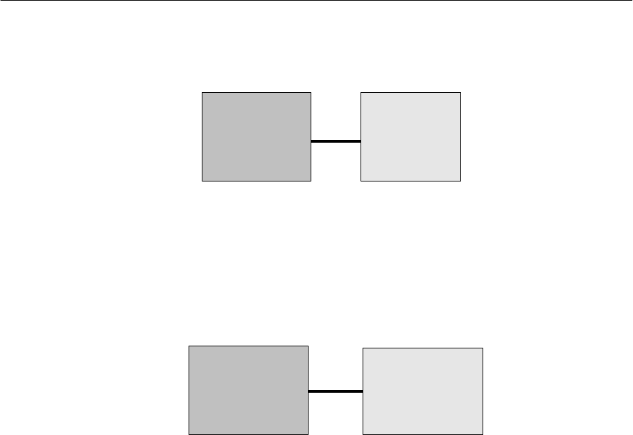
In the a dual-device configuration, the application software would also execute on top of the
BLE profiles and stack, and only the controller would be located on a separate device (please
see Figure 3).
Figure 3: Dual Device Configuration
However, allowing an application to be developed on one device while communicating with the
BLE stack executing on another allows access to the BLE stack that would not normally be
available (please see Figure 4).
Figure 4: Network Processor Configuration with HCI
This configuration provides is a very convenient configuration for creating a test development
environment where the “application” is actually a test tool that can execute scripts, generate
logs, etc. Note however that the HCI as defined by Bluetooth only allows Controller commands
and events. As such, a set of Vendor Specific commands and events will be used instead, and
that is what this document intends to convey.
3. Numerical Notation Conventions
Multiple-octets may be specified in hexadecimal notation in one of two ways:
Standard Hexadecimal Notation
In this notation, a single hexadecimal radix indicator “0x” precedes the entire value. The octet
order as read from left to right is from most significant octet to least significant octet. For
example, for the value 0x123456ABCDEF, ’12’ is the most significant octet and ‘EF’ is the least
significant octet.
Colon Separated Hexadecimal Notation
In this notation, the hexadecimal radix indicator “0x” is not used and octets are colon separated.
The octet order as read from left to right is from least significant octet to most significant octet.
For example, for the value 12:34:56:AB:CD:EF, ’12’ is the least significant octet and ‘EF’ is the
most significant octet.
Application
Profile
Host
HCI Controller
PC-Based
Application/
Profile
HCI Host
Controller

TI BLE HCI Vendor Specific HCI Guide
Page 10 of 195
Copyright © 2014-2015 Texas Instruments Inc.
4. Definitions, Abbreviations, Acronyms
ATT
Attribute Protocol
BC
Broadcast
BLE
Bluetooth Low Energy
BT
Bluetooth
CID
Channel ID
CMD
Command
CSG
Command Subgroup
EC
Event Code
EOEF
Event Opcode Event Field
EOGF
Event Opcode Group Field
ESG
Event Subgroup
GAP
Generic Access Profile
GATT
Generic Attribute Profile
HCI
Host Controller Interface
IDE
Integrated Development Environment
L2CAP
Logical Link Control and Adaptation Protocol
LE
Low Energy
LL
Link Layer
MPS
Maximum Payload Size
MTU
Maximum Transmission Unit
OCF
Opcode Command Field
OGF
Opcode Group Field
OTA
Over The Air
PB
Packet Boundary
PER
Packet Error Rate
PHY
Physical Layer
PPM
Parts Per Million
PSM
Protocol/Service Multiplexer
SCA
Sleep Clock Accuracy
SDU
Service Data Unit
SM
Security Manager
NV
Non-Volatile

TI BLE HCI Vendor Specific HCI Guide
Page 11 of 195
Copyright © 2014-2015 Texas Instruments Inc.
5. References
[1] Specification of the Bluetooth System, Core Version 4.0, June 30, 2010.
http://www.bluetooth.com/Specification%20Documents/Core_V40.zip
6. Revision History
Date (YMD)
Document version
Description of changes
2010-09-30
V1.0
Initial
2011-07-13
V1.1
BLE V1.1 RTM.
2011-12-02
V1.1b
BLE V1.1b RTM.
2012-03-16
V1.2.1
BLE V1.2.1 RTM
2012-05-18
V1.2.2
BLE V1.2.2 RTM
2012-12-13
V1.3
BLE V1.3 RTM
2013-04-18
V1.3.1
BLE V1.3.1 RTM
2013-06-14
V1.3.2
BLE V1.3.2 RTM
2013-11-12
V1.4.0
BLE V1.4 RTM
Section 10
new HCI extended commands:
HCI_EXT_SetSlaveLatencyOverrideCmd 0xFC1A
HCI_EXT_BuildRevisionCmd 0xFC1B
HCI_EXT_DelaySleepCmd 0xFC1C
HCI_EXT_ResetSystemCmd 0xFC1D
HCI_EXT_OverlappedProcessingCmd 0xFC1E
HCI_Ext_NumComplPktsLimitCmd 0xFC1F
Section 12.9
Changed parameter for GAP_TerminateLinkReq, added REASON parameter.
Section 12.17
New parameters GAP: TGAP_CONN_PAUSE_CENTRAL/PERIPHERAL.
Section 12.22.1
New GAP Bond Manager command 0x0410 ERASE_SINGLEBOND.
Section 14.3
New command: UTIL_Forceboot
2015-02-27
V2.0.0
BLE V2.0 RTM
Section 15
Added new commands for L2CAP Connection Oriented Channel feature
Section 16
Added new events for L2CAP Connection Oriented Channel feature
Marked all HCI commands as CC254x, CC264x, or both. Updated text.
Added Get Number Connections command and event.
Update BT Command/Event table for V4.1.
Added Set Event Mask Page 2 to BLE Commands Table 2.

TI BLE HCI Vendor Specific HCI Guide
Page 12 of 195
Copyright © 2014-2015 Texas Instruments Inc.
Updated wording in HCI_EXT_DelaySleep command.
Changed OnePacketPerEventCmd to OnePktPerEvtCmd to match code.
Section 12.17
Added test modes for L2CAP Connection Oriented Channel feature
Updated parameter descriptions with unit information
Added warning notes for HCI_EXT_SETbdaddrCmd,
HCI_EXT_PacketErrorRateCmd, and HCI_EXT_ConnEventNoticeCmd.
Section 13.6
Added connection role (connRole) field to GAP_LinkEstablished event
Section 14.4
Added UTIL_BuildRevision command
Sections 12.10/13 & 13.13/16
Added LE Secure Connection pairing (bit 3) to ‘authReq’ field
Section 13.11
Added LE Secure Connection pairing (bit 3) to ‘authState’ field
Make HCI_EXT_DelaySleepCmd defunct. Updated wording in HCI Extension
Reset System.
2015-04-01
V2.1.0
Updated HCI Extension Connection Event Notice for CC254x and CC264x.
Renamed and updated HCI Extension Get Number of Connections to HCI
Extension Get Connection Information.
Section 18.23
Added minimum encryption key size ‘encKeySize’ field to GATT_AddService
command.
Section 17.29
Added ATT Flow Control Violated event.
7. HCI Overview
The HCI is a standardized Bluetooth interface for sending commands, receiving events, and for
sending and receiving data. It is typically realized as a serial interface, using either RS232 or
USB communication devices. As the name implies, the HCI is used to bridge the Host and
Controller devices. Commands and Events can either be specified, or can be vendor specific for
extensibility. The following sections summarize the HCI protocol, the specification defined
commands and events used by BLE, and a detailed description of the vendor specific
commands and events defined by Texas Instruments Inc. For complete details on the HCI as
specified by the Special Interest Group (SIG), please see the Core specification [1].
8. Specification Interface
8.1 HCI Interface Protocol
The HCI supports four types of packets: Command Packet, Asynchronous Data Packet,
Synchronous Data Packet, and Event Packet. The packet type is a one byte value that
precedes the HCI packet. The packet type has the following values:
Packet
Packet Type
TI BLE HCI Vendor Specific HCI Guide
Page 13 of 195
Copyright © 2014-2015 Texas Instruments Inc.
Command
1
Asynchronous Data
2
Synchronous Data
3
Event
4
Table 1: HCI Packet Types
The contents of each packet are shown as follows (please see section 5.4 of [1], Vol. 2, Part E
for additional details).
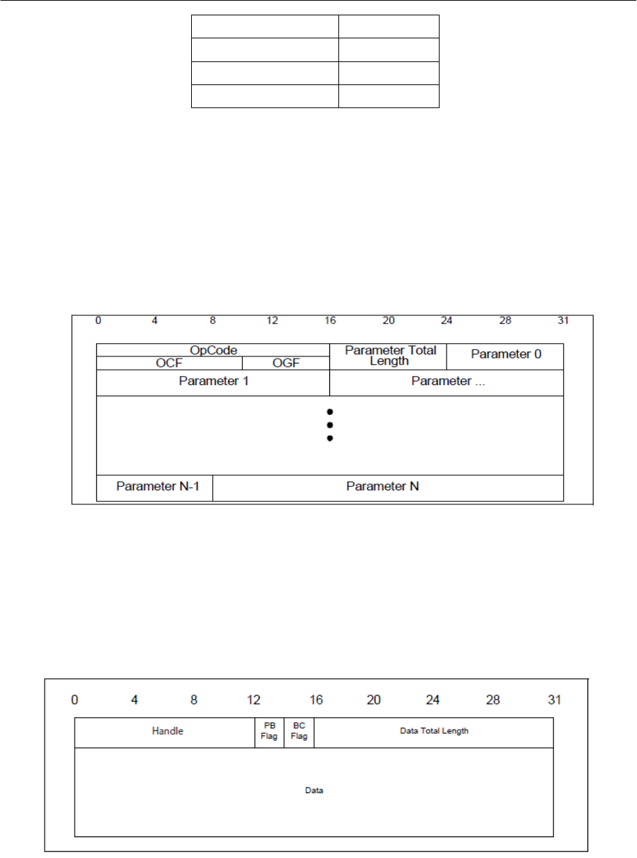
8.1.1 Command Packet
The command packet is comprised of the opcode, the number of parameters, and parameters
themselves.
Figure 5: Command Packet
8.1.2 Asynchronous Data Packet
The asynchronous data packet is comprised of the connection handle, fragmentation bits, the
number of data bytes, and the data bytes themselves.
Figure 6: Asynchronous Data Packet
TI BLE HCI Vendor Specific HCI Guide
Page 14 of 195
Copyright © 2014-2015 Texas Instruments Inc.
8.1.3 Synchronous Data Packet
This synchronous data packet is not used in BLE.
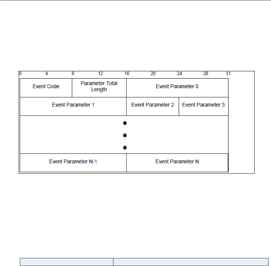
8.1.4 Event Packet
The event packet is comprised of the event code, the number of event parameters, and the
event parameters themselves.
Figure 7: Event Packet
8.2 HCI Command
HCI commands use a 16-bit opcode for identification. The opcode is subdivided into two parts: a
10-bit Opcode Command Field (OCF) and a 6-bit Opcode Group Field (OGF).
HCI Command Opcode
OGF OCF
15 10 9 0
The OGF values are defined by the Bluetooth (BT) Core specification. The LE specification has
its own OGF value. Also, there is an escape OGF value so that vendor specific OCF codes can
be used. The following OGF values are valid for BLE:
Link Control Commands: 1
Link Policy Commands: 2
Controller and Baseband Commands: 3
Informational Parameters: 4
Status Parameters: 5
Testing Commands: 6
LE Only Commands: 8

TI BLE HCI Vendor Specific HCI Guide
Page 15 of 195
Copyright © 2014-2015 Texas Instruments Inc.
Vendor Specific Commands: 63
The following table lists all specification BLE commands and their opcodes. Note that while all
commands can be used in a Network Processor Configuration with HCI, not all events will be
returned as they will be trapped and possibly discarded by the BLE Stack.
Commands
LE Commands
OGF
OCF
Opcode
LE Set Event Mask
8
1
0x2001
LE Read Buffer Size
8
2
0x2002
LE Read Local Supported Features
8
3
0x2003
LE Set Random Address
8
5
0x2005
LE Set Advertising Parameters
8
6
0x2006
LE Read Advertising Channel TX Power
8
7
0x2007
LE Set Advertising Data
8
8
0x2008
LE Set Scan Response Data
8
9
0x2009
LE Set Advertise Enable
8
10
0x200A
LE Set Scan Parameters
8
11
0x200B
LE Set Scan Enable
8
12
0x200C
LE Create Connection
8
13
0x200D
LE Create Connection Cancel
8
14
0x200E
LE Read White List Size
8
15
0x200F
LE Clear White List
8
16
0x2010
LE Add Device To White List
8
17
0x2011
LE Remove Device From White List
8
18
0x2012
LE Connection Update
8
19
0x2013
LE Set Host Channel Classification
8
20
0x2014
LE Read Channel Map
8
21
0x2015
LE Read Remote Used Features
8
22
0x2016
LE Encrypt
8
23
0x2017
LE Rand
8
24
0x2018
LE Start Encryption
8
25
0x2019
LE Long Term Key Requested Reply
8
26
0x201A
LE Long Term Key Requested Negative Reply
8
27
0x201B
LE Read Supported States
8
28
0x201C

TI BLE HCI Vendor Specific HCI Guide
Page 16 of 195
Copyright © 2014-2015 Texas Instruments Inc.
Commands
LE Commands
OGF
OCF
Opcode
LE Receiver Test
8
29
0x201D
LE Transmitter Test (max TX power for CC2541 is 0 dBm)
8
30
0x201E
LE Test End Command
8
31
0x201F
LE Remote Connection Parameter Request Reply
8
32
0x2020
LE Remote Connection Parameter Request Negative Reply
8
33
0x2021
Commands
BT Commands for LE
OGF
OCF
Opcode
Disconnect
1
6
0x0406
Read Remote Version Information
1
29
0x041D
Set Event Mask
3
1
0x0C01
Reset
3
3
0x0C03
Read Transmit Power Level
3
45
0x0C2D
Set Controller To Host Flow Control (optional)
3
49
0x0C31
Host Buffer Size (optional)
3
51
0x0C33
Host Number Of Completed Packets (optional)
3
53
0x0C35
Set Event Mask Page 2
3
63
0x0C63
Read Authenticated Payload Timeout
4
123
0x0C7B
Write Authenticated Payload Timeout
4
124
0x0C7C
Read Local Version Information
4
1
0x1001
Read Local Supported Commands (optional)
4
2
0x1002
Read Local Supported Features
4
3
0x1003
Read BD_ADDR
4
9
0x1009
Read RSSI
5
5
0x1405
Table 2: BLE Commands
8.3 HCI Events
HCI events use an 8-bit event code. All event codes are unique for BT and BLE. Only event
code 255 is reserved for vendor specific events. There is only one event code for all LE events.
The first event parameter is used as the subevent code to distinguish the LE event types.
The following table lists all the BLE events and their event codes, and subevent codes when
applicable:

TI BLE HCI Vendor Specific HCI Guide
Page 17 of 195
Copyright © 2014-2015 Texas Instruments Inc.
Events
LE Events
Event Code
Subevent Code
LE Connection Complete
0x3E
0x01
LE Advertising Report
0x3E
0x02
LE Connection Update Complete
0x3E
0x03
LE Read Remote Used Features Complete
0x3E
0x04
LE Long Term Key Requested
0x3E
0x05
LE Remote Connection Parameter Request
0x3E
0x06
BT Events
Event Code
Disconnection Complete
0x05
Encryption Change
0x08
Read Remote Version Information Complete
0x0C
Command Complete
0x0E
Command Status
0x0F
Hardware Error (optional)
0x10
Number Of Completed Packets
0x13
Data Buffer Overflow
0x1A
Encryption Key Refresh Complete
0x30
Authenticated Payload Timeout Expired
0x57
Table 3: BLE Events
9. Vendor Specific Interface
As mentioned, vendors can specify their own HCI commands and events by using the pre-
defined vendor specific opcode and vendor specific event code.
9.1 Vendor Specific Commands
A vendor specific opcode is indicated by an OGF value of 63. The vendor can use the remaining
10 bits (i.e. the OCF) as they like. TI defines its vendor specific OCF values by subdividing the
10 bits into a 3 MSB Command Subgroup (CSG) and a 7 LSB Command (CMD). The CSG is
used by the HCI to route the commands to a designated subsystem within the BLE stack. In this
way, vendor specific commands can be specified for any BLE stack layer.
HCI Vendor Specific Command Opcode, CSG=0..6
111111b Command
15 10 9 7 6 0
CSG (=0..6)
The Command Subgroups are defined as follows:

TI BLE HCI Vendor Specific HCI Guide
Page 18 of 195
Copyright © 2014-2015 Texas Instruments Inc.
CSG
Subgroup
0
HCI
1
L2CAP
2
ATT
3
GATT
4
GAP
5
UTIL
6
Reserved
7
User Profile
Table 4: Command Opcode Subgroups
For Command Subgroups 0 to 6, the remaining 7 bits of Command provide up to 128
commands for each subgroup. For Subgroup 7, the remaining 7 bits specify one of 128 profiles
and indicates that the subsequent byte is to be used as the command for that particular profile
(i.e. up to 256 commands per profile).
HCI Vendor Specific Command Opcode, CSG=7
Profile Command
111111b Profile ID
15 10 9 7 6 0
CSG (=7)
7 0
The following table lists all TI-specific HCI commands:
Vendor Specific Commands
LE Commands
OGF
CSG
CMD
Opcode
HCI Extension Set Rx Gain
63
0
0
0xFC00
HCI Extension Set Tx Power
63
0
1
0xFC01
HCI Extension One Packet Per Event
63
0
2
0xFC02
HCI Extension Clock Divide On Halt
63
0
3
0xFC03
HCI Extension Declare NV Usage
63
0
4
0xFC04
HCI Extension Decrypt
63
0
5
0xFC05
HCI Extension Set Local Supported Features
63
0
6
0xFC06
HCI Extension Set Fast Tx Response Time
63
0
7
0xFC07
HCI Extension Modem Test Tx
63
0
8
0xFC08

TI BLE HCI Vendor Specific HCI Guide
Page 19 of 195
Copyright © 2014-2015 Texas Instruments Inc.
Vendor Specific Commands
LE Commands
OGF
CSG
CMD
Opcode
HCI Extension Modem Hop Test Tx
63
0
9
0xFC09
HCI Extension Modem Test Rx
63
0
10
0xFC0A
HCI Extension End Modem Test
63
0
11
0xFC0B
HCI Extension Set BDADDR
63
0
12
0xFC0C
HCI Extension Set SCA
63
0
13
0xFC0D
HCI Extension Enable PTM1
63
0
14
0xFC0E
HCI Extension Set Frequency Tuning
63
0
15
0xFC0F
HCI Extension Save Frequency Tuning
63
0
16
0xFC10
HCI Extension Set Max DTM Tx Power
63
0
17
0xFC11
HCI Extension Map PM IO Port
63
0
18
0xFC12
HCI Extension Disconnect Immediate
63
0
19
0xFC13
HCI Extension Packet Error Rate
63
0
20
0xFC14
HCI Extension Packet Error Rate by Channel2
63
0
21
0xFC15
HCI Extension Extend RF Range
63
0
22
0xFC16
HCI Extension Advertiser Event Notice2
63
0
23
0xFC17
HCI Extension Connection Event Notice2
63
0
24
0xFC18
HCI Extension Halt During RF
63
0
25
0xFC19
HCI Extension Set Slave Latency Override
63
0
26
0xFC1A
HCI Extension Build Revision
63
0
27
0xFC1B
HCI Extension Delay Sleep
63
0
28
0xFC1C
HCI Extension Reset System
63
0
29
0xFC1D
HCI Extension Overlapped Processing
63
0
30
0xFC1E
HCI Extension Number Completed Packets Limit
63
0
31
0xFC1F
HCI Extension Get Connection Information
63
0
32
0xFC20
L2CAP Disconnection Request
63
1
6
0xFC86
L2CAP Connection Parameter Update Request
63
1
18
0xFC92
L2CAP Connection Request
63
1
20
0xFC94
L2CAP Connection Response
63
1
21
0xFC95
L2CAP Flow Control Credit
63
1
22
0xFC96
L2CAP Data
63
1
112
0xFCF0
1
Not supported by HCI; only direct function call is allowed. No event is returned.
2
Not supported by HCI; only direct function call is allowed. No event is returned.

TI BLE HCI Vendor Specific HCI Guide
Page 20 of 195
Copyright © 2014-2015 Texas Instruments Inc.
Vendor Specific Commands
LE Commands
OGF
CSG
CMD
Opcode
L2CAP Register PSM
63
1
113
0xFCF1
L2CAP Deregister PSM
63
1
114
0xFCF2
L2CAP PSM Info
63
1
115
0xFCF3
L2CAP PSM Channels
63
1
116
0xFCF4
L2CAP Channel Info
63
1
117
0xFCF5
ATT Error Response
63
2
1
0xFD01
ATT Exchange MTU Request
63
2
2
0xFD02
ATT Exchange MTU Response
63
2
3
0xFD03
ATT Find Information Request
63
2
4
0xFD04
ATT Find Information Response
63
2
5
0xFD05
ATT Find By Type Value Request
63
2
6
0xFD06
ATT Find By Type Value Response
63
2
7
0xFD07
ATT Read By Type Request
63
2
8
0xFD08
ATT Read By Type Response
63
2
9
0xFD09
ATT Read Request
63
2
10
0xFD0A
ATT Read Response
63
2
11
0xFD0B
ATT Read Blob Request
63
2
12
0xFD0C
ATT Read Blob Response
63
2
13
0xFD0D
ATT Read Multiple Request
63
2
14
0xFD0E
ATT Read Multiple Response
63
2
15
0xFD0F
ATT Read By Group Type Request
63
2
16
0xFD10
ATT Read By Group Type Response
63
2
17
0xFD11
ATT Write Request
63
2
18
0xFD12
ATT Write Response
63
2
19
0xFD13
ATT Prepare Write Request
63
2
22
0xFD16
ATT Prepare Write Response
63
2
23
0xFD17
ATT Execute Write Request
63
2
24
0xFD18
ATT Execute Write Response
63
2
25
0xFD19
ATT Handle Value Notification
63
2
27
0xFD1B
ATT Handle Value Indication
63
2
29
0xFD1D
ATT Handle Value Confirmation
63
2
30
0xFD1E
GATT Discover Characteristics By UUID
63
3
8
0xFD88
GATT Write Long
63
3
22
0xFD96

TI BLE HCI Vendor Specific HCI Guide
Page 21 of 195
Copyright © 2014-2015 Texas Instruments Inc.
Vendor Specific Commands
LE Commands
OGF
CSG
CMD
Opcode
GAP Device Initialization
63
4
0
0xFE00
GAP Configure Device Address
63
4
3
0xFE03
GAP Device Discovery Request
63
4
4
0xFE04
GAP Device Discovery Cancel
63
4
5
0xFE05
GAP Make Discoverable
63
4
6
0xFE06
GAP Update Advertising Data
63
4
7
0xFE07
GAP End Discoverable
63
4
8
0xFE08
GAP Establish Link Request
63
4
9
0xFE09
GAP Terminate Link Request
63
4
10
0xFE0A
GAP Authenticate
63
4
11
0xFE0B
GAP Passkey Update
63
4
12
0xFE0C
GAP Slave Security Request
63
4
13
0xFE0D
GAP Signable
63
4
14
0xFE0E
GAP Bond
63
4
15
0xFE0F
GAP Terminate Auth
63
4
16
0xFE10
GAP Update Link Parameter Request
63
4
17
0xFE11
GAP Set Parameter
63
4
48
0xFE30
GAP Get Parameter
63
4
49
0xFE31
GAP Resolve Private Address
63
4
50
0xFE32
GAP Set Advertisement Token
63
4
51
0xFE33
GAP Remove Advertisement Token
63
4
52
0xFE34
GAP Update Advertisement Tokens
63
4
53
0xFE35
GAP Bond Set Parameter
63
4
54
0xFE36
GAP Bond Get Parameter
63
4
55
0xFE37
UTIL Reserved
63
5
0
0xFE80
UTIL NV Read
63
5
1
0xFE81
UTIL NV Write
63
5
2
0xFE82
Reserved
63
6
0
0xFF00
User Profiles
63
7
0
0xFF80
Table 5: Vendor Specific Commands

TI BLE HCI Vendor Specific HCI Guide
Page 22 of 195
Copyright © 2014-2015 Texas Instruments Inc.
9.2 Vendor Specific Events
A vendor specific event code is indicated by a value of 255. The vendor must then use event
parameters (following the length byte) to specify vendor specific events. TI defines the following
two bytes as the Event Opcode.
0xFF
Event Code
7 0 7 0 15 0
Event Opcode
Length
The Event Opcode was chosen to mirror the Command Opcode by dividing it into two parts: a 6
bit Event Opcode Group Field (EOGF), and a 10 bit Event Opcode Event Field (EOEF).
Event Opcode
EOGF EOEF
15 10 9 0
The EOEF is again chosen to mirror the Command OCF by dividing it into two parts: the Event
Subgroup (ESG) and the Event.
Event Opcode
EOGF ESG
15 10 9 7 6 0
Event
The EOGF is defined as follows:
EOGF
Group
0
Embedded Opcode
1
Core Opcode
2
Profile Request
3
Profile Response
4 .. 63
Reserved
Table 6: Event Opcode Group
The ESG is defined as in Table 4. The Events are as defined in the following table. Please note
that the value of the Events cannot be less than 0x400 as the first 1024 values are reserved.
The reason for this has to do with Client/Server Request/Response Tunneling, which is
described in the following section. Tunneling requires embedding Command Opcodes in HCI
Events. When this is done, the EOGF is zero, and the remaining 10 bits is the Command
Opcode. In order to prevent Command and Event Opcode overlap, the first 1024 values are
reserved in the Event Opcode space. Also note that the Event Code (EC) is always 0xFF since
normally only Controller events are returned via the HCI.

TI BLE HCI Vendor Specific HCI Guide
Page 23 of 195
Copyright © 2014-2015 Texas Instruments Inc.
Vendor Specific Events
LE Events
EC
EOGF
ESG
Event
Opcode
HCI Extension Set Rx Gain
0xFF
1
0
0
0x0400
HCI Extension Set Tx Power
0xFF
1
0
1
0x0401
HCI Extension One Packet Per Event
0xFF
1
0
2
0x0402
HCI Extension Clock Divide On Halt
0xFF
1
0
3
0x0403
HCI Extension Declare NV Usage
0xFF
1
0
4
0x0404
HCI Extension Decrypt
0xFF
1
0
5
0x0405
HCI Extension Set Local Supported Features
0xFF
1
0
6
0x0406
HCI Extension Set Fast Tx Response Time
0xFF
1
0
7
0x0407
HCI Extension Modem Test Tx
0xFF
1
0
8
0x0408
HCI Extension Modem Hop Test Tx
0xFF
1
0
9
0x0409
HCI Extension Modem Test Rx
0xFF
1
0
10
0x040A
HCI Extension End Modem Test
0xFF
1
0
11
0x040B
HCI Extension Set BDADDR
0xFF
1
0
12
0x040C
HCI Extension Set SCA
0xFF
1
0
13
0x040D
HCI Extension Enable PTM3
0xFF
1
0
14
0x040E
HCI Extension Set Frequency Tuning
0xFF
1
0
15
0x040F
HCI Extension Save Frequency Tuning
0xFF
1
0
16
0x0410
HCI Extension Set Max DTM Tx Power
0xFF
1
0
17
0x0411
HCI Extension Map PM IO Port
0xFF
1
0
18
0x0412
HCI Extension Disconnect Immediate
0xFF
1
0
19
0x0413
HCI Extension Packet Error Rate
0xFF
1
0
20
0x0414
HCI Extension Packet Error Rate by Channel3
0xFF
1
0
21
0x0415
HCI Extension Extend RF Range
0xFF
1
0
22
0x0416
HCI Extension Advertiser Event Notice3
0xFF
1
0
23
0x0417
HCI Extension Connection Event Notice3
0xFF
1
0
24
0x0418
HCI Extension Halt During RF
0xFF
1
0
25
0x0419
HCI Extension Set Slave Latency Override
0xFF
1
0
26
0x041A
HCI Extension Build Revision
0xFF
1
0
27
0x041B
HCI Extension Delay Sleep
0xFF
1
0
28
0x041C
HCI Extension Reset System
0xFF
1
0
29
0x041D
3
Not supported by HCI; only direct function call is allowed. No event is returned.

TI BLE HCI Vendor Specific HCI Guide
Page 24 of 195
Copyright © 2014-2015 Texas Instruments Inc.
Vendor Specific Events
LE Events
EC
EOGF
ESG
Event
Opcode
HCI Extension Overlapped Processing
0xFF
1
0
30
0x041E
HCI Extension Number Completed Packets Limit
0xFF
1
0
31
0x041F
HCI Extension Get Connection Information
0xFF
1
0
32
0x0420
L2CAP Command Reject
0xFF
1
1
1
0x0481
L2CAP Connection Parameter Update Response
0xFF
1
1
19
0x0493
L2CAP Connection Request
0xFF
1
1
20
0x0494
L2CAP Channel Established
0xFF
1
1
96
0x04E0
L2CAP Channel Terminated
0xFF
1
1
97
0x04E1
L2CAP Out Of Credit
0xFF
1
1
98
0x04E2
L2CAP Peer Credit Threshold
0xFF
1
1
99
0x04E3
L2CAP Send SDU Done
0xFF
1
1
100
0x04E4
L2CAP Data
0xFF
1
1
112
0x04F0
ATT Error Response
0xFF
1
2
1
0x0501
ATT Exchange MTU Request
0xFF
1
2
2
0x0502
ATT Exchange MTU Response
0xFF
1
2
3
0x0503
ATT Find Information Request
0xFF
1
2
4
0x0504
ATT Find Information Request
0xFF
1
2
5
0x0505
ATT Find By Type Value Request
0xFF
1
2
6
0x0506
ATT Find By Type Value Response
0xFF
1
2
7
0x0507
ATT Read By Type Request
0xFF
1
2
8
0x0508
ATT Read By Type Response
0xFF
1
2
9
0x0509
ATT Read Request
0xFF
1
2
10
0x050A
ATT Read Response
0xFF
1
2
11
0x050B
ATT Read Blob Request
0xFF
1
2
12
0x050C
ATT Read Blob Response
0xFF
1
2
13
0x050D
ATT Read Multiple Request
0xFF
1
2
14
0x050E
ATT Read Multiple Response
0xFF
1
2
15
0x050F
ATT Read By Group Type Request
0xFF
1
2
16
0x0510
ATT Read By Group Type Response
0xFF
1
2
17
0x0511
ATT Write Request
0xFF
1
2
18
0x0512
ATT Write Response
0xFF
1
2
19
0x0513
ATT Prepare Write Request
0xFF
1
2
22
0x0516
ATT Prepare Write Response
0xFF
1
2
23
0x0517

TI BLE HCI Vendor Specific HCI Guide
Page 25 of 195
Copyright © 2014-2015 Texas Instruments Inc.
Vendor Specific Events
LE Events
EC
EOGF
ESG
Event
Opcode
ATT Execute Write Request
0xFF
1
2
24
0x0518
ATT Execute Write Response
0xFF
1
2
25
0x0519
ATT Handle Value Notification
0xFF
1
2
27
0x051B
ATT Handle Value Indication
0xFF
1
2
29
0x051D
ATT Handle Value Confirmation
0xFF
1
2
30
0x051E
GAP Device Init Done
0xFF
1
4
0
0x0600
GAP Device Discovery
0xFF
1
4
1
0x0601
GAP Advert Data Update Done
0xFF
1
4
2
0x0602
GAP Make Discoverable Done
0xFF
1
4
3
0x0603
GAP End Discoverable Done
0xFF
1
4
4
0x0604
GAP Link Established
0xFF
1
4
5
0x0605
GAP Link Terminated
0xFF
1
4
6
0x0606
GAP Link Parameter Update
0xFF
1
4
7
0x0607
GAP Random Address Changed
0xFF
1
4
8
0x0608
GAP Signature Updated
0xFF
1
4
9
0x0609
GAP Authentication Complete
0xFF
1
4
10
0x060A
GAP Passkey Needed
0xFF
1
4
11
0x060B
GAP Slave Requested Security
0xFF
1
4
12
0x060C
GAP Device Information
0xFF
1
4
13
0x060D
GAP Bond Complete
0xFF
1
4
14
0x060E
GAP Pairing Requested
0xFF
1
4
15
0x060F
Command Status
0xFF
1
4
127
0x067F
Table 7: Vendor Specific Events
You will note that there are two EOGF values for Profiles. At this time, no profiles are defined
well enough to document here. These values are defined in anticipation of not only needing
large numbers of profiles and their commands, but also of needing the direction the command
is travelling when embedded in an HCI Command or Event. You can see that ATT does not
have this issue as these commands are already defined using even values for commands and
odd values for events, and thus, direction is distinguishable. For profiles, it is not yet known how
the commands and events will be defined.
TI BLE HCI Vendor Specific HCI Guide
Page 26 of 195
Copyright © 2014-2015 Texas Instruments Inc.
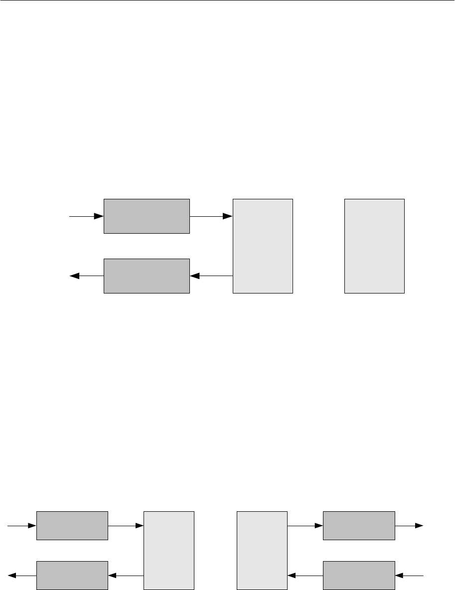
9.3 Request and Response Tunneling
In the Client/Server model defined and supported by the BLE stack, the Client sends Requests
to the Server and the Server sends Responses back to the Client. The Requests sent by the
Client may be handled by a Server on the same device, or they may travel OTA to the Server on
another device. Similarly, the Response sent by the Server may be handled by a Client on the
same device, or may be sent OTA to a Client on another device from which the request came.
But in either case, as long as the Requests and Responses remain within the scope of the BLE
stack software (i.e. the BLE Server database is on the device), the BLE stack remains
unconcerned about whether the Requests and Responses are sent/received by the same
device or are from another device. Please see Figure 8.
Figure 8: Request/Response with Server Database in BLE Stack
However, when using the Network Processor Configuration with HCI such that the Server
database is not located on the device, then Requests and Reponses have to be mapped into
HCI Commands and Events. The HCI is specified such that only Commands are sent from the
Host to the Controller, and only Events are sent from the Controller to the Host. If the Server
database is located on say a PC, then when an OTA Request is received by the Server device,
it must be sent to the PC via the HCI. Even though the Request started out on one end as an
HCI Command, it must be provided to the remote PC as an HCI event on the other. Similarly,
when the PC sends the Response on one end, which will be an HCI Event to the remote PC on
the other, it must be sent to the device as an HCI Command. Thus, the Request, which starts
out as an HCI Command, must be embedded in an HCI Event when received by the remote PC,
and the Response, which starts out as an HCI Command, must be embedded in an HCI Event
when received by the remote PC. In this way, Requests and Responses are being tunneled in
HCI Commands and Events. Please see Figure 9.
Figure 9: Request/Response with Server Database not in BLE Stack
HCI
Server Response Server
Response
HCI Event
Client Request HCI
Client
Request
HCI Command
BLE Device
(Network
Processor
Configuration
with HCI)
BLE Device
(Single Device
Configuration)
OTA
HCI Server
Response
HCI Command
Server Response
HCI Client
Request
HCI Event
Client Request
HCI
Server Response Server
Response
HCI Event
Client Request HCI
Client
Request
HCI Command
BLE Device
(Network
Processor
Configuration
with HCI)
BLE Device
(Network
Processor
Configuration
with HCI)
OTA

TI BLE HCI Vendor Specific HCI Guide
Page 27 of 195
Copyright © 2014-2015 Texas Instruments Inc.
10. HCI Extension Vendor Specific Commands
In addition to the BLE HCI commands, the following HCI Extension vendor specific commands are also
available. Please note that some of these commands may not be supported on the CC264x platform.
10.1 HCI Extension Set Receiver Gain
Command
Opcode
Command Parameters
Return Parameters
HCI_EXT_SetRxGainCmd
0xFC00
rxGain
Status
Description
CC254x:
CC264x:
This command is used to set the RF receiver gain. The default system value for this feature is standard
receiver gain.
Command Parameters
rxGain: (1 byte)
Value
Parameter Description
0x00
HCI_EXT_RX_GAIN_STD
0x01
HCI_EXT_RX_GAIN_HIGH
Return Parameters
Status: (1 byte)
Value
Parameter Description
0x00
HCI_SUCCESS
Event(s) Generated
When the HCI_EXT_SetRxGainCmd has completed, a vendor specific Command Complete event shall
be generated.

TI BLE HCI Vendor Specific HCI Guide
Page 28 of 195
Copyright © 2014-2015 Texas Instruments Inc.
10.2 HCI Extension Set Transmitter Power
Command
Opcode
Command Parameters
Return Parameters
HCI_EXT_SetTxPowerCmd
0xFC01
txPower
Status
Description
CC254x:
CC264x:
This command is used to set the RF transmitter output power. The default system value for this feature
is 0 dBm. Note that for the CC254x platform, a setting of 4dBm is only allowed for the CC2540.
Command Parameters
txPower: (1 byte) - CC254x
Value
Parameter Description
0x00
HCI_EXT_TX_POWER_MINUS_23_DBM
0x01
HCI_EXT_TX_POWER_MINUS_6_DBM
0x02
HCI_EXT_TX_POWER_0_DBM
0x03
HCI_EXT_TX_POWER_4_DBM (CC2540 only)
txPower: (1 byte) - CC264x
Value
Parameter Description
0x00
HCI_EXT_TX_POWER_MINUS_21_DBM
0x01
HCI_EXT_TX_POWER_MINUS_18_DBM
0x02
HCI_EXT_TX_POWER_MINUS_15_DBM
0x03
HCI_EXT_TX_POWER_MINUS_12_DBM
0x04
HCI_EXT_TX_POWER_MINUS_9_DBM
0x05
HCI_EXT_TX_POWER_MINUS_6_DBM
0x06
HCI_EXT_TX_POWER_MINUS_3_DBM
0x07
HCI_EXT_TX_POWER_0_DBM
0x08
HCI_EXT_TX_POWER_1_DBM
0x09
HCI_EXT_TX_POWER_2_DBM
0x0A
HCI_EXT_TX_POWER_3_DBM
0x0B
HCI_EXT_TX_POWER_4_DBM
0x0C
HCI_EXT_TX_POWER_5_DBM

TI BLE HCI Vendor Specific HCI Guide
Page 29 of 195
Copyright © 2014-2015 Texas Instruments Inc.
Return Parameters
Status: (1 byte)
Value
Parameter Description
0x00
HCI_SUCCESS
Event(s) Generated
When the HCI_EXT_SetTxPowerCmd has completed, a vendor specific Command Complete event
shall be generated.

TI BLE HCI Vendor Specific HCI Guide
Page 30 of 195
Copyright © 2014-2015 Texas Instruments Inc.
10.3 HCI Extension One Packet Per Event
Command
Opcode
Command Parameters
Return Parameters
HCI_EXT_OnePktPerEvtCmd
0xFC02
control
Status
Description
CC254x:
CC264x:
This command is used to configure the Link Layer to only allow one packet per connection event. The
default system value for this feature is disabled.
This command can be used to tradeoff throughput and power consumption during a connection. When
enabled, power can be conserved during a connection by limiting the number of packets per connection
event to one, at the expense of more limited throughput. When disabled, the number of packets
transferred during a connection event is not limited, at the expense of higher power consumption.
Command Parameters
control: (1 byte)
Value
Parameter Description
0x00
HCI_EXT_DISABLE_ONE_PKT_PER_EVT
0x01
HCI_EXT_ENABLE_ONE_PKT_PER_EVT
Return Parameters
Status: (1 byte)
Value
Parameter Description
0x00
HCI_SUCCESS
Event(s) Generated
When the HCI_EXT_OnePktPerEvtCmd has completed, a vendor specific Command Complete event
shall be generated.

TI BLE HCI Vendor Specific HCI Guide
Page 31 of 195
Copyright © 2014-2015 Texas Instruments Inc.
10.4 HCI Extension Clock Divide On Halt
Command
Opcode
Command Parameters
Return Parameters
HCI_EXT_ClkDivOnHaltCmd
0xFC03
control
Status
Description
CC254x:
CC264x:
This command is used to configure the Link Layer to divide the system clock when the MCU is halted
during a radio operation. The default system value for this feature is disabled.
Note: This command is only valid when the MCU is halted during RF operation (please see
HCI_EXT_HaltDuringRfCmd).
Command Parameters
control: (1 byte)
Value
Parameter Description
0x00
HCI_EXT_DISABLE_CLK_DIVIDE_ON_HALT
0x01
HCI_EXT_ENABLE_CLK_DIVIDE_ON_HALT
Return Parameters
Status: (1 byte)
Value
Parameter Description
0x00
HCI_SUCCESS
Event(s) Generated
When the HCI_EXT_ClkDivOnHaltCmd has completed, a vendor specific Command Complete event
shall be generated.

TI BLE HCI Vendor Specific HCI Guide
Page 32 of 195
Copyright © 2014-2015 Texas Instruments Inc.
10.5 HCI Extension Declare NV Usage
Command
Opcode
Command Parameters
Return Parameters
HCI_EXT_DeclareNvUsageCmd
0xFC04
mode
Status
Description
CC254x:
CC264x:
This command is used to inform the Controller whether the Host is using NV memory during BLE
operations. The default system value for this feature is NV In Use.
When the NV is not in use during BLE operations, the Controller is able to bypass internal checks that
reduce overhead processing, thereby reducing average power consumption.
Note: This command is only allowed when the BLE Controller is idle.
Note: Using NV when declaring it is not in use may result in a hung BLE Connection.
Command Parameters
control: (1 byte)
Value
Parameter Description
0x00
HCI_EXT_NV_NOT_IN_USE
0x01
HCI_EXT_NV_IN_USE
Return Parameters
Status: (1 byte)
Value
Parameter Description
0x00
HCI_SUCCESS
Event(s) Generated
When the HCI_EXT_DeclareNvUsageCmd has completed, a vendor specific Command Complete
event shall be generated.

TI BLE HCI Vendor Specific HCI Guide
Page 33 of 195
Copyright © 2014-2015 Texas Instruments Inc.
10.6 HCI Extension Decrypt
Command
Opcode
Command Parameters
Return Parameters
HCI_EXT_DecryptCmd
0xFC05
key, encText
Status
Description
CC254x:
CC264x:
This command is used to decrypt encrypted text using AES128.
Command Parameters
key: (16 bytes)
Value
Parameter Description
0xXXXXXXXXXXXXXXX
XXXXXXXXXXXXXXXXX
128 bit key for the decryption of the data given in the command.
The most significant octet of the data corresponds to key[0] using
the notation specified in FIPS 197.
encText: (16 bytes)
Value
Parameter Description
0xXXXXXXXXXXXXXXX
XXXXXXXXXXXXXXXXX
128 bit encrypted data to be decrypted. The most significant octet
of the key corresponds to key[0] using the notation specified in
FIPS 197.
Return Parameters
Status: (1 byte)
Value
Parameter Description
0x00
HCI_SUCCESS
Event(s) Generated
When the HCI_EXT_DecryptCmd has completed, a vendor specific Command Complete event shall
be generated.

TI BLE HCI Vendor Specific HCI Guide
Page 34 of 195
Copyright © 2014-2015 Texas Instruments Inc.
10.7 HCI Extension Set Local Supported Features
Command
Opcode
Command Parameters
Return Parameters
HCI_EXT_SetLocalSupportedFeaturesCmd
0xFC06
localFeatures
Status
Description
CC254x:
CC264x:
This command is used to set the Controller’s Local Supported Features. For a complete list of
supported LE features, please see [1], Part B, Section 4.6.
Note: This command can be issued either before or after one or more connections are formed.
However, the local features set in this manner are only effective if performed before a Feature
Exchange Procedure has been initiated by the Master. Once this control procedure has been completed
for a particular connection, only the exchanged feature set for that connection will be used. Since the
Link Layer may initiate the feature exchange procedure autonomously, it is best to use this command
before the connection is formed.
Command Parameters
localFeatures: (8 bytes) – CC254x
Value
Parameter Description
0x0000000000000001
Encryption Feature
0xFFFFFFFFFFFFFFFE
Reserved for future use
localFeatures: (8 bytes) – CC264x
Value
Parameter Description
0x0000000000000001
Encryption Feature
0x0000000000000002
Connection Parameters Request Feature
0x0000000000000004
Extended Reject Indication Feature
0x0000000000000008
Slave Features Exchange Feature
0x0000000000000010
Ping Feature
0xFFFFFFFFFFFFFFFE
Reserved for future use
Return Parameters
Status: (1 byte)
Value
Parameter Description
0x00
HCI_SUCCESS
Event(s) Generated
When the HCI_EXT_SetLocalSupportedFeaturesCmd has completed, a vendor specific Command
Complete event shall be generated.

TI BLE HCI Vendor Specific HCI Guide
Page 35 of 195
Copyright © 2014-2015 Texas Instruments Inc.
10.8 HCI Extension Set Fast Transmit Response Time
Command
Opcode
Command Parameters
Return Parameters
HCI_EXT_SetFastTxResponseTimeCmd
0xFC07
control
Status
Description
CC254x:
CC264x:
This command is used to configure the Link Layer fast transmit response time feature. The default
system value for this feature is enabled.
Note: This command is only valid for a Slave controller.
When the Host transmits data, the controller (by default) ensures the packet is sent over the LL
connection with as little delay as possible, even when the connection is configured to use slave latency.
That is, the transmit response time will tend to be no longer than the connection interval. This results in
lower power savings since the LL may need to wake to transmit during connection events that would
normally have been skipped. If saving power is more critical than fast transmit response time, then this
feature can be disabled using this command. When disabled, the transmit response time will be no
longer than slave latency + 1 times the connection interval.
Command Parameters
control: (1 byte)
Return Parameters
Status: (1 byte)
Value
Parameter Description
0x00
HCI_SUCCESS
Event(s) Generated
When the HCI_EXT_SetFastTxResponseTimeCmd has completed, a vendor specific Command
Complete event shall be generated.
Value
Parameter Description
0x00
HCI_EXT_DISABLE_FAST_TX_RESP_TIME
0x01
HCI_EXT_ENABLE_FAST_TX_RESP_TIME

TI BLE HCI Vendor Specific HCI Guide
Page 36 of 195
Copyright © 2014-2015 Texas Instruments Inc.
10.9 HCI Extension Modem Test Transmit
Command
Opcode
Command Parameters
Return Parameters
HCI_EXT_ModemTestTxCmd
0xFC08
cwMode, txFreq
Status
Description
CC254x:
CC264x:
This API is used to start a continuous transmitter modem test, using either a modulated or unmodulated
carrier wave tone, at the frequency that corresponds to the specified RF channel. Use the
HCI_EXT_EndModemTest command to end the test.
Note: The RF channel, not the BLE frequency, is specified! You can obtain the RF channel from the
BLE frequency as follows: RF Channel = (BLE Frequency – 2402) / 2.
Note: When the HCI_EXT_EndModemTest is issued to stop this test, a Controller reset will take place.
Note: The device will transmit at the default output power (0 dBm) unless changed by
HCI_EXT_SetTxPowerCmd.
Note: This modem test can be used to satisfy in part radio regulation requirements as specific in
standards such as ARIB STD-T66.
Command Parameters
cwMode: (1 byte)
t
txFreq: (1 bytes)
Value
Parameter Description
0..39
RF channel of transmit frequency.
Return Parameters
Status: (1 byte)
Value
Parameter Description
0x00
HCI_SUCCESS
Event(s) Generated
When the HCI_EXT_ModemTestTxCmd has completed, a vendor specific Command Complete event
shall be generated.
Value
Parameter Description
0x00
HCI_EXT_TX_MODULATED_CARRIER
0x01
HCI_EXT_TX_UNMODULATED_CARRIER

TI BLE HCI Vendor Specific HCI Guide
Page 37 of 195
Copyright © 2014-2015 Texas Instruments Inc.
10.10 HCI Extension Modem Hop Test Transmit
Command
Opcode
Command Parameters
Return Parameters
HCI_EXT_ModemHopTestTxCmd
0xFC09
Status
Description
CC254x:
CC264x:
This API is used to start a continuous transmitter direct test mode test using a modulated carrier wave
and transmitting a 37 byte packet of pseudo-random 9 bit data. A packet is transmitted on a different
frequency (linearly stepping through all RF channels 0..39) every 625us. Use the
HCI_EXT_EndModemTest command to end the test.
Note: When the HCI_EXT_EndModemTest is issued to stop this test, a Controller reset will take place.
Note: The device will transmit at the default output power (0 dBm) unless changed by
HCI_EXT_SetTxPowerCmd.
Note: This modem test can be used to satisfy in part radio regulation requirements as specific in
standards such as ARIB STD-T66.
Command Parameters:
None
Return Parameters
Status: (1 byte)
Value
Parameter Description
0x00
HCI_SUCCESS
Event(s) Generated
When the HCI_EXT_ModemHopTestTxCmd has completed, a vendor specific Command Complete
event shall be generated.

TI BLE HCI Vendor Specific HCI Guide
Page 38 of 195
Copyright © 2014-2015 Texas Instruments Inc.
10.11 HCI Extension Modem Test Receive
Command
Opcode
Command Parameters
Return Parameters
HCI_EXT_ModemTestRxCmd
0xFC0A
rxFreq
Status
Description
CC254x:
CC264x:
This API is used to start a continuous receiver modem test using a modulated carrier wave tone, at the
frequency that corresponds to the specific RF channel. Any received data is discarded. Receiver gain
may be adjusted using the HCI_EXT_SetRxGain command. RSSI may be read during this test by using
the HCI_ReadRssi command. Use HCI_EXT_EndModemTest command to end the test.
Note: The RF channel, not the BLE frequency, is specified! You can obtain the RF channel from the
BLE frequency as follows: RF Channel = (BLE Frequency – 2402) / 2.
Note: When the HCI_EXT_EndModemTest is issued to stop this test, a Controller reset will take place.
Note: This modem test can be used to satisfy in part radio regulation requirements as specific in
standards such as ARIB STD-T66.
Command Parameters
rxFreq: (1 bytes)
Value
Parameter Description
0..39
RF channel of receive frequency.
Return Parameters
Status: (1 byte)
Value
Parameter Description
0x00
HCI_SUCCESS
Event(s) Generated
When the HCI_EXT_ModemTestRxCmd has completed, a vendor specific Command Complete event
shall be generated.

TI BLE HCI Vendor Specific HCI Guide
Page 39 of 195
Copyright © 2014-2015 Texas Instruments Inc.
10.12 HCI Extension End Modem Test
Command
Opcode
Command Parameters
Return Parameters
HCI_EXT_EndModemTestCmd
0xFC0B
Status
Description
CC254x:
CC264x:
This API is used to end a modem test. A Controller reset will take place.
Command Parameters
None
Return Parameters
Status: (1 byte)
Value
Parameter Description
0x00
HCI_SUCCESS
Event(s) Generated
When the HCI_EXT_EndModemTestCmd has completed, a vendor specific Command Complete
event shall be generated.

TI BLE HCI Vendor Specific HCI Guide
Page 40 of 195
Copyright © 2014-2015 Texas Instruments Inc.
10.13 HCI Extension Set BDADDR
Command
Opcode
Command Parameters
Return Parameters
HCI_EXT_SetBDADDRCmd
0xFC0C
bdAddr
Status
Description
CC254x:
CC264x:
This command is used to set this device’s BLE address (BDADDR). This address will override the
device’s address determined when the device is reset (i.e. a hardware reset, not an HCI Controller
Reset). To restore the device’s initialized address, issue this command with an invalid address.
Note: This command is only allowed when the Controller is in the Standby state.
Note: This command is intended to only be used during initialization. Changing the device’s BDADDR
after various BLE operations have already taken place may cause unexpected problems.
Command Parameters
bdAddr: (6 bytes)
Return Parameters
Status: (1 byte)
Value
Parameter Description
0x00
HCI_SUCCESS
Event(s) Generated
When the HCI_EXT_SetBDADDRCmd has completed, a vendor specific Command Complete event
shall be generated.
Value
Parameter Description
0x000000000000..
0xFFFFFFFFFFFE
Valid BLE device address.
0xFFFFFFFFFFFF
Invalid BLE device address. Used to restore the device address to
that which was determined at initialization.

TI BLE HCI Vendor Specific HCI Guide
Page 41 of 195
Copyright © 2014-2015 Texas Instruments Inc.
10.14 HCI Extension Set SCA
Command
Opcode
Command Parameters
Return Parameters
HCI_EXT_SetSCACmd
0xFC0D
scaInPPM
Status
Description
CC254x:
CC264x:
This command is used to set this device’s Sleep Clock Accuracy (SCA) value, in parts per million
(PPM), from 0 to 500. For a Master device, the value is converted to one of eight ordinal values
representing a SCA range (per [1], Volume 6, Part B, Section 2.3.3.1, Table 2.2), which will be used
when a connection is created. For a Slave device, the value is directly used. The system default value
for a Master and Slave device is 50ppm and 40ppm, respectively.
Note: This command is only allowed when the device is not in a connection.
Note: The device’s SCA value remains unaffected by an HCI Reset.
Command Parameters
scaInPPM: (2 bytes)
Return Parameters
Status: (1 byte)
Value
Parameter Description
0x00
HCI_SUCCESS
Event(s) Generated
When the HCI_EXT_SetSCACmd has completed, a vendor specific Command Complete event shall be
generated.
Value
Parameter Description
0..0x1F4
Valid SCA value.
0x01F5..0xFFFF
Invalid SCA value.

TI BLE HCI Vendor Specific HCI Guide
Page 42 of 195
Copyright © 2014-2015 Texas Instruments Inc.
10.15 HCI Extension Enable PTM
Command
Opcode
Command Parameters
Return Parameters
HCI_EXT_EnablePTMCmd
0xFC0E
Status
Description
CC254x:
CC264x:
This command is used to enable Production Test Mode (PTM). This mode is used by the customer
during assembly of their product to allow limited access to the BLE Controller for testing and
configuration. This command is only available when the BLE Controller is built without external access
to the Controller (i.e. when no transport interface such as RS232 is permitted). This mode will remain
enabled until the device is reset. Please see the related application note for additional details.
Note: This command is only allowed as a direct function call, and is only intended to be used by an
embedded application. No vendor specific Command Complete event will be generated.
Command Parameters
None
Return Parameters
Status: (1 byte)
Value
Parameter Description
0x00
HCI_SUCCESS
0x0C
HCI_ERROR_CODE_CMD_DISALLOWED
Event(s) Generated
When the HCI_EXT_EnablePTMCmd has completed, it will simply return. No vendor specific
Command Complete event will be generated.

TI BLE HCI Vendor Specific HCI Guide
Page 43 of 195
Copyright © 2014-2015 Texas Instruments Inc.
10.16 HCI Extension Set Frequency Tuning
Command
Opcode
Command Parameters
Return Parameters
HCI_EXT_SetFreqTuneCmd
0xFC0F
step
Status
Description
CC254x:
CC264x:
This PTM-only command is used to set this device’s Frequency Tuning either up one step or down one
step. When the current setting is already at its max value, then stepping up will have no effect. When
the current setting is already at its min value, then stepping down will have no effect. This setting will
only remain in effect until the device is reset unless HCI_EXT_SaveFreqTuneCmd is used to save it in
non-volatile memory.
Command Parameters
mode: (1 bytes)
Return Parameters
Status: (1 byte)
Value
Parameter Description
0x00
HCI_SUCCESS
Event(s) Generated
When the HCI_EXT_SetFreqTuneCmd has completed, a vendor specific Command Complete event
shall be generated.
Value
Parameter Description
0
HCI_PTM_SET_FREQ_TUNE_DOWN
1
HCI_PTM_SET_FREQ_TUNE_UP

TI BLE HCI Vendor Specific HCI Guide
Page 44 of 195
Copyright © 2014-2015 Texas Instruments Inc.
10.17 HCI Extension Save Frequency Tuning
Command
Opcode
Command Parameters
Return Parameters
HCI_EXT_SaveFreqTuneCmd
0xFC10
Status
Description
CC254x:
CC264x:
This PTM-only command is used to save this device’s Frequency Tuning setting in non-volatile memory.
This setting will be used by the BLE Controller upon reset, and when waking from Sleep.
Command Parameters
None
Return Parameters
Status: (1 byte)
Value
Parameter Description
0x00
HCI_SUCCESS
Event(s) Generated
When the HCI_EXT_SaveFreqTuneCmd has completed, a vendor specific Command Complete event
shall be generated.

TI BLE HCI Vendor Specific HCI Guide
Page 45 of 195
Copyright © 2014-2015 Texas Instruments Inc.
10.18 HCI Extension Set Max DTM Transmitter Power
Command
Opcode
Command Parameters
Return Parameters
HCI_EXT_SetMaxDtmTxPowerCmd
0xFC11
txPower
Status
Description
CC254x:
CC264x:
This command is used to override the RF transmitter output power used by the Direct Test Mode
(DTM). Normally, the maximum transmitter output power setting used by DTM is the maximum
transmitter output power setting for the device (i.e. 4 dBm for the CC2540; 0 dBm for the CC2541; 5
dBm for the CC264x). This command will change the value used by DTM.
Note: When DTM is ended by a call to HCI_LE_TestEndCmd, or a HCI_Reset is used, the transmitter
output power setting is restored to the default value of 0 dBm.
Command Parameters
txPower: (1 byte) – CC254x
Value
Parameter Description
0x00
HCI_EXT_TX_POWER_MINUS_23_DBM
0x01
HCI_EXT_TX_POWER_MINUS_6_DBM
0x02
HCI_EXT_TX_POWER_0_DBM
0x03
HCI_EXT_TX_POWER_4_DBM (CC2540 only)
txPower: (1 byte) - CC264x
Value
Parameter Description
0x00
HCI_EXT_TX_POWER_MINUS_21_DBM
0x01
HCI_EXT_TX_POWER_MINUS_18_DBM
0x02
HCI_EXT_TX_POWER_MINUS_15_DBM
0x03
HCI_EXT_TX_POWER_MINUS_12_DBM
0x04
HCI_EXT_TX_POWER_MINUS_9_DBM
0x05
HCI_EXT_TX_POWER_MINUS_6_DBM
0x06
HCI_EXT_TX_POWER_MINUS_3_DBM
0x07
HCI_EXT_TX_POWER_0_DBM
0x08
HCI_EXT_TX_POWER_1_DBM
0x09
HCI_EXT_TX_POWER_2_DBM
0x0A
HCI_EXT_TX_POWER_3_DBM
0x0B
HCI_EXT_TX_POWER_4_DBM
0x0C
HCI_EXT_TX_POWER_5_DBM

TI BLE HCI Vendor Specific HCI Guide
Page 46 of 195
Copyright © 2014-2015 Texas Instruments Inc.
Return Parameters
Status: (1 byte)
Value
Parameter Description
0x00
HCI_SUCCESS
Event(s) Generated
When the HCI_EXT_SetMaxDtmTxPowerCmd has completed, a vendor specific Command Complete
event shall be generated.

TI BLE HCI Vendor Specific HCI Guide
Page 47 of 195
Copyright © 2014-2015 Texas Instruments Inc.
10.19 HCI Extension Map PM IO Port
Command
Opcode
Command Parameters
Return Parameters
HCI_EXT_MapPmInOutPortCmd
0xFC12
ioPort, ioPin
Status
Description
CC254x:
CC264x:
This command is used to configure and map a CC254x I/O Port as a General-Purpose I/O (GPIO)
output signal that reflects the Power Management (PM) state of the CC254x device. The GPIO output
will be High on Wake, and Low upon entering Sleep. This feature can be disabled by specifying
HCI_EXT_PM_IO_PORT_NONE for the ioPort (ioPin is then ignored). The system default value upon
hardware reset is disabled.
This command can be used to control an external DC-DC Converter (its actual intent) such has the TI
TPS62730 (or any similar converter that works the same way). This command should be used with
extreme care as it will override how the Port/Pin was previously configured! This includes the
mapping of Port 0 pins to 32kHz clock output, Analog I/O, UART, Timers; Port 1 pins to Observables,
Digital Regulator status, UART, Timers; Port 2 pins to an external 32kHz XOSC. The selected Port/Pin
will be configured as an output GPIO with interrupts masked. Careless use can result in a
reconfiguration that could disrupt the system. For example, if the Port/Pin is being used as part of the
serial interface for the device, the Port/Pin will be reconfigured from its original Peripheral function to a
GPIO, disrupting the serial port. It is therefore the user’s responsibility to ensure the selected
Port/Pin does not cause any conflicts in the system.
Note: Only Pins 0, 3 and 4 are valid for Port 2 since Pins 1 and 2 are mapped to debugger signals DD
and DC.
Note: Port/Pin signal change will obviously only occur when Power Savings is enabled.
Note: The CC254xEM modules map the TI TPS62730 control signal to P1.2, which happens to map to
the SmartRF05EB LCD Chip Select. Thus, the LCD can’t be used when setup this way.
Command Parameters
ioPort: (1 byte)
Value
Parameter Description
0x00
HCI_EXT_PM_IO_PORT_P0
0x01
HCI_EXT_PM_IO_PORT_P1
0x02
HCI_EXT_PM_IO_PORT_P2
0xFF
HCI_EXT_PM_IO_PORT_NONE
ioPin: (1 byte)
Value
Parameter Description
0x00
HCI_EXT_PM_IO_PORT_PIN0
0x01
HCI_EXT_PM_IO_PORT_PIN1
0x02
HCI_EXT_PM_IO_PORT_PIN2

TI BLE HCI Vendor Specific HCI Guide
Page 48 of 195
Copyright © 2014-2015 Texas Instruments Inc.
Value
Parameter Description
0x03
HCI_EXT_PM_IO_PORT_PIN3
0x04
HCI_EXT_PM_IO_PORT_PIN4
0x05
HCI_EXT_PM_IO_PORT_PIN5
0x06
HCI_EXT_PM_IO_PORT_PIN6
0x07
HCI_EXT_PM_IO_PORT_PIN7
Return Parameters
Status: (1 byte)
Value
Parameter Description
0x00
HCI_SUCCESS
Event(s) Generated
When the HCI_EXT_MapPmIoPortCmd has completed, a vendor specific Command Complete event
shall be generated.

TI BLE HCI Vendor Specific HCI Guide
Page 49 of 195
Copyright © 2014-2015 Texas Instruments Inc.
10.20 HCI Extension Disconnect Immediate
Command
Opcode
Command Parameters
Return Parameters
HCI_EXT_DisconnectImmedCmd
0xFC13
connHandle
Status
Description
CC254x:
CC264x:
This command is used to disconnect a connection immediately. This command can be useful for when
a connection needs to be ended without the latency associated with the normal BLE Controller
Terminate control procedure.
Note that the Host issuing the command will still receive the HCI Disconnection Complete event with a
Reason status of 0x16 (i.e. Connection Terminated by Local Host), followed by an HCI Vendor Specific
Event.
Command Parameters
connHandle: (2 bytes)
Value
Parameter Description
0x0000 .. 0x0EFF
Connection Handle to be used to identify a connection.
Note: 0x0F00 – 0x0FFF are reserved for future use.
Return Parameters
Status: (1 byte)
Value
Parameter Description
0x00
HCI_SUCCESS
Event(s) Generated
When the HCI_EXT_DisconnectImmedCmd has completed, an HCI Disconnection Complete event
followed by a vendor specific Command Complete event shall be generated.

TI BLE HCI Vendor Specific HCI Guide
Page 50 of 195
Copyright © 2014-2015 Texas Instruments Inc.
10.21 HCI Extension Packet Error Rate
Command
Opcode
Command Parameters
Return Parameters
HCI_EXT_PacketErrorRateCmd
0xFC14
connHandle, command
Status
Description
CC254x:
CC264x:
This command is used to Reset or Read the Packet Error Rate counters for a connection. When Reset,
the counters are cleared; when Read, the total number of packets received, the number of packets
received with a CRC error, the number of events, and the number of missed events are returned. The
system default value upon hardware reset is Reset.
Note: The counters are only 16 bits. At the shortest connection interval, this provides a little over 8
minutes of data.
Note: This command is only valid for a valid connection handle (i.e. for an active connection). It is
therefore not possible to read the packet error rate data once the connection has ended.
Command Parameters
connHandle: (2 bytes)
Value
Parameter Description
0x0000 .. 0x0EFF
Connection Handle to be used to identify a connection.
Note: 0x0F00 – 0x0FFF are reserved for future use.
command: (1 byte)
Value
Parameter Description
0x00
HCI_EXT_PER_RESET
0x01
HCI_EXT_PER_READ
Return Parameters
Status: (1 byte)
Value
Parameter Description
0x00
HCI_SUCCESS
Event(s) Generated
When the HCI_EXT_PacketErrorRateCmd has completed, a vendor specific Command Complete
event followed by a vendor specific Command Complete event shall be generated.

TI BLE HCI Vendor Specific HCI Guide
Page 51 of 195
Copyright © 2014-2015 Texas Instruments Inc.
10.22 HCI Extension Packet Error Rate By Channel
Command
Opcode
Command Parameters
Return Parameters
HCI_EXT_PERbyChanCmd
0xFC15
connHandle, *perByChan
Status
Description
CC254x:
CC264x:
This command is used to start or end Packet Error Rate by Channel counter accumulation for a
connection, and can be used by an application to make Coexistence assessments. Based on the
results, an application can perform an Update Channel Classification command to limit channel
interference from other wireless standards. If *perByChan is NULL, counter accumulation will be
discontinued. If *perByChan is not NULL, then it is assumed that there is sufficient memory for the
PER data, based on the following type definition perByChan_t located in ll.h:
#define LL_MAX_NUM_DATA_CHAN 37
// Packet Error Rate Information By Channel
typedef struct
{
uint16 numPkts[ LL_MAX_NUM_DATA_CHAN ];
uint16 numCrcErr[ LL_MAX_NUM_DATA_CHAN ];
} perByChan_t;
Note: This command is only allowed as a direct function call, and is only intended to be used by an
embedded application.
Note: It is the user’s responsibility to ensure there is sufficient memory allocated! The user is also
responsible for maintaining the counters, clearing them if required before starting accumulation.
Note: As indicated, the counters are 16 bits. At the shortest connection interval, this provides a bit over 8
minutes of data.
Note: This command can be used in combination with HCI_EXT_PacketErrorRateCmd.
Command Parameters
connHandle: (2 bytes)
Value
Parameter Description
0x0000 .. 0x0EFF
Connection Handle to be used to identify a connection.
Note: 0x0F00 – 0x0FFF are reserved for future use.
*perByChan: (2 bytes)
Value
Parameter Description
NULL
End counter accumulation.
Non-NULL
Start counter accumulation by channel.

TI BLE HCI Vendor Specific HCI Guide
Page 52 of 195
Copyright © 2014-2015 Texas Instruments Inc.
Return Parameters
Status: (1 byte)
Value
Parameter Description
0x00
HCI_SUCCESS
Event(s) Generated
When the HCI_EXT_PERbyChanCmd has completed, a vendor specific Command Complete event
shall be generated.

TI BLE HCI Vendor Specific HCI Guide
Page 53 of 195
Copyright © 2014-2015 Texas Instruments Inc.
10.23 HCI Extension Extend RF Range
Command
Opcode
Command Parameters
Return Parameters
HCI_EXT_ExtendRfRangeCmd
0xFC16
Status
Description
CC254x:
CC264x:
This command is used to configure the CC254x to automatically control the TI CC2590 2.4GHz RF
Front End device. Using the CC2590 allows a maximum Tx output power of 10dBm (the specified BLE
maximum), and increases Rx sensitivity, thus extending the RF range of the CC254x. Once this
command is used, the configuration will not change unless the CC254x is reset.
Automatic control of the CC2590 is achieved using the CC254x Observables, which take control of
GPIO P1.2 and P1.3. The GPIO P1.1 is also taken to control RF gain. These GPIOs are therefore not
available when using this feature.
This command can be used in combination with HCI_EXT_SetTxPowerCmd, resulting in a cumulative
Tx output power. Therefore, for the CC2540 only, attempting to set Tx output power to 4dBm (i.e. using
HCI_EXT_TX_POWER_4_DBM), will instead set the Tx output power to 0dBm.
The command HCI_EXT_SetRxGainCmd should be used to set the Rx gain per usual. That is, the
CC254x Rx Standard/High gain setting is mirrored to the CC2590 High Gain Mode (HGM) Low/High
setting.
When this command is used, the CC254x Tx output power and Rx gain will retain their previous values,
unless the previous Tx output power value was set to 4dBm on the CC2540. In this case, as previously
explained, the value will be set to 0dBm.
Command Parameters
None
Return Parameters
Status: (1 byte)
Value
Parameter Description
0x00
HCI_SUCCESS
Event(s) Generated
When the HCI_EXT_ExtendRfRangeCmd has completed, a vendor specific Command Complete
event shall be generated.

TI BLE HCI Vendor Specific HCI Guide
Page 54 of 195
Copyright © 2014-2015 Texas Instruments Inc.
10.24 HCI Extension Advertiser Event Notice
Command
Opcode
Command Parameters
Return Parameters
HCI_EXT_AdvEventNoticeCmd
0xFC17
taskID, taskEvent
Status
Description
CC254x:
CC264x:
This command is used to configure the device to set a user task’s event when an Advertisement event
completes. Only a single task event value is allowed (i.e. must be a power of two). A non-zero taskEvent
value is taken to be "enable", while a zero valued taskEvent is taken to be "disable". The default value is
“disable”.
Note: This command is only allowed as a direct function call, and is only intended to be used by an
embedded application. No vendor specific Command Complete event will be generated.
Command Parameters
taskID: (1 byte)
Value
Parameter Description
0x00..0xFF
OSAL task ID.
taskEvent: (2 bytes)
Value
Parameter Description
20..214
OSAL task event. Note that 215 is a reserved system task
event.
Return Parameters
Status: (1 byte)
Value
Parameter Description
0x00
HCI_SUCCESS
0x12
HCI_ERROR_CODE_INVALID_HCI_CMD_PARAMS
Event(s) Generated
When the HCI_EXT_AdvEventNoticeCmd has completed, it will simply return. No vendor specific
Command Complete event will be generated.

TI BLE HCI Vendor Specific HCI Guide
Page 55 of 195
Copyright © 2014-2015 Texas Instruments Inc.
10.25 HCI Extension Connection Event Notice
Command
Opcode
Command Parameters
Return Parameters
HCI_EXT_ConnEventNoticeCmd
0xFC18
connHandle, taskID,
taskEvent
Status
Description
CC254x:
CC264x:
This command is used to configure the device to set a user task’s event when a Connection event
completes. Only a single task event value is allowed (i.e. must be a power of two). A non-zero taskEvent
value is taken to be "enable", while a zero valued taskEvent is taken to be "disable". The default value is
“disable”.
Note: This command does not check if the taskID and/or taskEvent are valid!
Note: This feature is automatically disabled once the connection ends, and therefore this command
must be called each time another connection is formed in order to continue its use.
Note: This command is only allowed as a direct function call, and is only intended to be used by an
embedded application. No vendor specific Command Complete event will be generated.
Command Parameters
connHandle: (2 byte, 12 bits meaningful)
Value
Parameter Description
0xXXXX
Identifies the connection to which this event notice applies. Range:
0x0000-0x0EFF (0x0F00-0x0FFF Reserved for future use).
taskID: (1 byte)
Value
Parameter Description
0x00..0xFF
OSAL task ID.
taskEvent: (2 bytes)
Value
Parameter Description
20..214
OSAL task event. Note that 215 is a reserved system task event.
Return Parameters
Status: (1 byte)
Value
Parameter Description
0x00
HCI_SUCCESS
0x02
HCI_ERROR_CODE_UNKNOWN_CONN_ID
0x12
HCI_ERROR_CODE_INVALID_HCI_CMD_PARAMS

TI BLE HCI Vendor Specific HCI Guide
Page 56 of 195
Copyright © 2014-2015 Texas Instruments Inc.
Event(s) Generated
When the HCI_EXT_ConnEventNoticeCmd has completed, it will simply return. No vendor specific
Command Complete event will be generated.
10.26 HCI Extension Halt During RF
Command
Opcode
Command Parameters
Return Parameters
HCI_EXT_HaltDuringRfCmd
0xFC19
mode
Status
Description
CC254x:
CC264x:
This command is used to enable or disable the halting of the MCU while the radio is operating. When
the MCU is not halted, the peak current is higher, but the system is more responsive. When the MCU is
halted, the peak current consumption is reduced, but the system is less responsive. The default value is
Enable.
Note: This command will be disallowed if there are any active BLE connections.
Note: The HCI_EXT_ClkDivOnHaltCmd will be disallowed if the halt during RF is not enabled.
Command Parameters
mode: (1 byte)
Value
Parameter Description
0x00
HCI_EXT_HALT_DURING_RF_DISABLE
0x01
HCI_EXT_HALT_DURING_RF_ENABLE
Return Parameters
Status: (1 byte)
Value
Parameter Description
0x00
HCI_SUCCESS
Event(s) Generated
When the HCI_EXT_HaltDuringRfCmd has completed, a vendor specific Command Complete event
shall be generated.

TI BLE HCI Vendor Specific HCI Guide
Page 57 of 195
Copyright © 2014-2015 Texas Instruments Inc.
10.27 HCI Extension Set Slave Latency Override
Command
Opcode
Command Parameters
Return Parameters
HCI_EXT_SetSlaveLatencyOverrideCmd
0xFC1A
mode
Status
Description
CC254x:
CC264x:
This command is used to enable or disable the Slave Latency Override, allowing the user to ensure that
Slave Latency is not applied even though it is active. The default value is Disable.
Note: This command will be disallowed for no connection, or the connection is not in the Slave role.
Command Parameters
mode: (1 byte)
Value
Parameter Description
0x00
HCI_EXT_DISABLE_SL_OVERRIDE
0x01
HCI_EXT_ENABLE_SL_OVERRIDE
Return Parameters
Status: (1 byte)
Value
Parameter Description
0x00
HCI_SUCCESS
Event(s) Generated
When the HCI_EXT_SetSlaveLatencyOverrideCmd has completed, a vendor specific Command
Complete event shall be generated.

TI BLE HCI Vendor Specific HCI Guide
Page 58 of 195
Copyright © 2014-2015 Texas Instruments Inc.
10.28 HCI Extension Build Revision
Command
Opcode
Command Parameters
Return Parameters
HCI_EXT_BuildRevisionCmd
0xFC1B
mode, userRevNum
Status
Description
CC254x:
CC264x:
This command is used to a) allow the embedded user code to set their own 16 bit revision number, and
b) to read the build revision number of the BLE stack library software. The default value of the user
revision number is zero.
When the user updates a BLE project by adding their own code, they may use this API to set their own
revision number. When called with mode set to HCI_EXT_SET_APP_REVISION, the stack will save
this value. No event will be returned from this API when used this way as it is intended to be called from
within the target itself. Note however that this does not preclude this command from being received via
the HCI. However, no event will be returned.
When this API is used from the HCI, then the second parameter is ignored, and a vendor specific event
is returned with the user’s revision number and the build revision number of the BLE stack.
Command Parameters
mode: (1 byte)
Value
Parameter Description
0x00
HCI_EXT_SET_APP_REVISION
0x01
HCI_EXT_READ_BUILD_REVISION
userRevNum: (2 bytes)
Value
Parameter Description
0xXXXX
Any 16 bit value the application wishes to use as their revision
number.
Return Parameters
Status: (1 byte)
Value
Parameter Description
0x00
HCI_SUCCESS
Event(s) Generated
When the HCI_EXT_BuildRevisionCmd has completed, a vendor specific Command Complete event
shall be generated, but only when the value of mode is HCI_EXT_READ_BUILD_REVISION.

TI BLE HCI Vendor Specific HCI Guide
Page 59 of 195
Copyright © 2014-2015 Texas Instruments Inc.
10.29 HCI Extension Delay Sleep
Command
Opcode
Command Parameters
Return Parameters
HCI_EXT_DelaySleepCmd
0xFC1C
delay
Status
Description
CC254x:
CC264x:
This command is used to set the delay before sleep occurs after Reset or upon waking from sleep to
allow the external 32kHz crystal to stabilize. If this command is never used, the default delay is 400ms
on the CC254x. This command is no longer supported on the CC264x platform.
If the customer’s hardware requires a different delay or does not require this delay at all, it can be
changed by calling this command during their OSAL task initialization. A zero delay value will eliminate
the delay after Reset and (unless changed again) all subsequent wakes from sleep; a non-zero delay
value will change the delay after Reset and (unless changed again) all subsequent wakes from sleep.
If this command is used any time after system initialization, then the new delay value will be applied the
next time the delay is used.
Note: This delay only applies to Reset and Sleep. If a periodic timer is used, or a BLE operation is
active, then only Sleep is used, and this delay will only occur after Reset.
Note: There is no distinction made between a hard and soft reset. The delay (if non-zero) will be applied
the same way in either case.
Command Parameters
delay: (2 bytes)
Value
Parameter Description
0x0000..0x03E8
In milliseconds.
Return Parameters
Status: (1 byte)
Value
Parameter Description
0x00
HCI_SUCCESS
Event(s) Generated
When the HCI_EXT_DelaySleepCmd has completed, a vendor specific Command Complete event
shall be generated.

TI BLE HCI Vendor Specific HCI Guide
Page 60 of 195
Copyright © 2014-2015 Texas Instruments Inc.
10.30 HCI Extension Reset System
Command
Opcode
Command Parameters
Return Parameters
HCI_EXT_ResetSystemCmd
0xFC1D
mode
Status
Description
CC254x:
CC264x: (Hard Reset Only)
This command is used to issue a hard or soft system reset. On the CC254x, a hard reset is caused by a
watchdog timer timeout, while a soft reset is caused by resetting the PC to zero. On the CC264x, a hard
reset is caused by setting the SYSRESET bit in the System Controller Reset Control register. The soft
reset is currently not supported on the CC264x.
Command Parameters
mode: (1 byte)
Value
Parameter Description
0x00
HCI_EXT_RESET_SYSTEM_HARD
0x01
HCI_EXT_RESET_SYSTEM_SOFT (CC254x only)
Return Parameters
Status: (1 byte)
Value
Parameter Description
0x00
HCI_SUCCESS
Event(s) Generated
When the HCI_EXT_ResetSystemCmd has completed, a vendor specific Command Complete
event shall be generated.

TI BLE HCI Vendor Specific HCI Guide
Page 61 of 195
Copyright © 2014-2015 Texas Instruments Inc.
10.31 HCI Extension Overlapped Processing
Command
Opcode
Command Parameters
Return Parameters
HCI_EXT_OverlappedProcessingCmd
0xFC1E
mode
Status
Description
CC254x:
CC264x:
This command is used to enable or disable overlapped processing. The default is disabled.
Command Parameters
mode: (1 byte)
Value
Parameter Description
0x00
HCI_EXT_DISABLE_OVERLAPPED_PROCESSING
0x01
HCI_EXT_ENABLE_OVERLAPPED_PROCESSING
Return Parameters
Status: (1 byte)
Value
Parameter Description
0x00
HCI_SUCCESS
Event(s) Generated
When the HCI_EXT_OverlappedProcessingCmd has completed, a vendor specific Command
Complete event shall be generated.

TI BLE HCI Vendor Specific HCI Guide
Page 62 of 195
Copyright © 2014-2015 Texas Instruments Inc.
10.32 HCI Extension Number Completed Packets Limit
Command
Opcode
Command
Parameters
Return
Parameters
HCI_EXT_NumComplPktsLimitCmd
0xFC1F
limit, flushOnEvt
Status
Description
CC254x:
CC264x:
This command is used to set the limit on the minimum number of complete packets before a Number of
Completed Packets event is returned by the Controller. If the limit is not reached by the end of a
connection event, then the Number of Completed Packets event will be returned (if non-zero) based on
the flushOnEvt flag. The limit can be set from one to the maximum number of HCI buffers (please see
the LE Read Buffer Size command in the Bluetooth Core specification). The default limit is one; the
default flushOnEvt flag is FALSE.
Command Parameters
limit: (1 byte)
Value
Parameter Description
0x01..<max buffers>
Where <max buffers> is returned by HCI_LE_ReadBufSizeCmd.
flushOnEvt: (1 byte)
Value
Parameter Description
0x00
Only return a Number of Completed Packets event when the
number of completed packets is greater than or equal to the limit.
0x01
Return a Number of Complete Packets event if the number of
completed packets is less than the limit.
Return Parameters
Status: (1 byte)
Value
Parameter Description
0x00
HCI_SUCCESS
Event(s) Generated
When the HCI_EXT_NumComplPktsLimitCmd has completed, a vendor specific Command
Complete event shall be generated.

TI BLE HCI Vendor Specific HCI Guide
Page 63 of 195
Copyright © 2014-2015 Texas Instruments Inc.
10.33 HCI Extension Get Connection Information
Command
Opcode
Command Parameters
Return
Parameters
HCI_EXT_GetConnInfoCmd
0xFC20
*numAllocConns,
*numActiveConns,
*activeConnInfo
Status
Description
CC254x:
CC264x:
This command (which replaces Get Number Connections) is used to get the number of allocated
connections, the number of active connections, and for each active connection, the connection handle,
the connection role, the peer device address and peer device address type. The number of allocated
connections is based on a default build value that can be changed in the project using
MAX_NUM_BLE_CONNS (please see the software user’s guide for additional details). The number of
active connections refers to active BLE connections. The information per connection is based on the
structure hciConnInfo_t provided in hci.h.
If all parameters are NULL, then the call to this command is considered a network processor call via a
transport layer, and the results will be provided via a vendor specific command complete event.
If any parameter is not NULL, then the call to this command is considered a direct function call and the
valid pointers will be used to store the result. In this case, it is the user’s responsibility to ensure
there is sufficient memory allocated! Note that partial results can be obtained by selective use of the
pointers. For example, if only the number of active connections is desired, this can be obtained as
follows:
uint8 numActiveConns;
(void)HCI_EXT_GetConnInfoCmd( NULL, &numActiveConns, NULL );
Command Parameters
*numAllocConns: (1 byte)
Value
Parameter Description
NULL
Invalid pointer.
Non-NULL
Pointer for the number of allocated connections (1 byte).
*numActiveConns: (1 byte)
Value
Parameter Description
NULL
Invalid pointer.
Non-NULL
Pointer for the number of active connections (1 byte).

TI BLE HCI Vendor Specific HCI Guide
Page 64 of 195
Copyright © 2014-2015 Texas Instruments Inc.
*activeConnInfo: (N bytes)
Value
Parameter Description
NULL
Invalid pointer.
Non-NULL
Pointer for the connection information for each active connection,
which consists of: Connection ID, Connection Role, Peer Device
Address, and Peer Address Type, which will require (Number Of
Active Connections * 9 bytes) of memory.
Return Parameters
Status: (1 byte)
Value
Parameter Description
0x00
HCI_SUCCESS
Event(s) Generated
When the HCI_EXT_GetConnInfoCmd has completed, a vendor specific Command Complete
event shall be generated if all command parameters were NULL.

TI BLE HCI Vendor Specific HCI Guide
Page 65 of 195
Copyright © 2014-2015 Texas Instruments Inc.
11. HCI Extension Vendor Specific Events
The HCI Extension vendor specific commands generate the following vendor specific events. Please
see the corresponding command to determine whether this event is supported on the CC254x and/or
CC264x.
11.1 HCI Extension Set Receiver Gain
Event
Opcode
Event Parameters
HCI_Vendor_Specific_Event
0x0400
Status, cmdOpcode
Description
This event is sent to indicate the RF receiver gain has been set, or that there was an error.
Event Parameters
Status: (1 byte)
Value
Parameter Description
0x00
HCI_SUCCESS
0x12
HCI_ERROR_CODE_INVALID_HCI_CMD_PARAMS
cmdOpcode: (2 bytes)
Value
Parameter Description
0xFC00
HCI Extension Set Receiver Gain Command
11.2 HCI Extension Set Transmitter Power
Event
Opcode
Event Parameters
HCI_Vendor_Specific_Event
0x0401
Status, cmdOpcode
Description
This event is sent to indicate the RF transmitter power has been set, or that there was an error.
Event Parameters
Status: (1 byte)
Value
Parameter Description
0x00
HCI_SUCCESS
0x12
HCI_ERROR_CODE_INVALID_HCI_CMD_PARAMS
cmdOpcode: (2 bytes)
Value
Parameter Description
0xFC01
HCI Extension Set Transmitter Power Command

TI BLE HCI Vendor Specific HCI Guide
Page 66 of 195
Copyright © 2014-2015 Texas Instruments Inc.
11.3 HCI Extension One Packet Per Event
Event
Opcode
Event Parameters
HCI_Vendor_Specific_Event
0x0402
Status, cmdOpcode
Description
This event is sent to indicate the One Packet Per Event feature has been enabled or disabled, or that
there was an error.
Event Parameters
Status: (1 byte)
Value
Parameter Description
0x00
HCI_SUCCESS
0x12
HCI_ERROR_CODE_INVALID_HCI_CMD_PARAMS
cmdOpcode: (2 bytes)
Value
Parameter Description
0xFC02
HCI Extension One Packet Per Event Command
11.4 HCI Extension Clock Divide On Halt
Event
Opcode
Event Parameters
HCI_Vendor_Specific_Event
0x0403
Status, cmdOpcode
Description
This event is sent to indicate the Clock Divide On Halt feature has been enabled or disabled, or that
there was an error.
Event Parameters
Status: (1 byte)
Value
Parameter Description
0x00
HCI_SUCCESS
0x0C
HCI_ERROR_CODE_CMD_DISALLOWED
0x12
HCI_ERROR_CODE_INVALID_HCI_CMD_PARAMS
cmdOpcode: (2 bytes)
Value
Parameter Description
0xFC03
HCI Extension Clock Divide On Halt Command

TI BLE HCI Vendor Specific HCI Guide
Page 67 of 195
Copyright © 2014-2015 Texas Instruments Inc.
11.5 HCI Extension Declare NV Usage
Event
Opcode
Event Parameters
HCI_Vendor_Specific_Event
0x0404
Status, cmdOpcode
Description
This event is sent to indicate the Declare NV Usage feature has been set, or that there was an error.
Event Parameters
Status: (1 byte)
Value
Parameter Description
0x00
HCI_SUCCESS
0x0C
HCI_ERROR_CODE_CMD_DISALLOWED
0x12
HCI_ERROR_CODE_INVALID_HCI_CMD_PARAMS
cmdOpcode: (2 bytes)
Value
Parameter Description
0xFC04
HCI Extension Declare NV Usage Command
11.6 HCI Extension Decrypt
Event
Opcode
Event Parameters
HCI_Vendor_Specific_Event
0x0405
Status, cmdOpcode, plainTextData
Description
This event is sent to indicate Decryption has completed.
Event Parameters
Status: (1 byte)
Value
Parameter Description
0x00
HCI_SUCCESS
cmdOpcode: (2 bytes)
Value
Parameter Description
0xFC05
HCI Extension Decrypt Command
plainTextData: (16 bytes)
Value
Parameter Description
0xXXXXXXXXXXXXXXX
XXXXXXXXXXXXXXXXX
128 bit decrypted data block. The most significant octet of
plainTextData corresponds to plainTextData [0] using the notation
specified in FIPS 197.

TI BLE HCI Vendor Specific HCI Guide
Page 68 of 195
Copyright © 2014-2015 Texas Instruments Inc.
11.7 HCI Extension Set Local Supported Features
Event
Opcode
Event Parameters
HCI_Vendor_Specific_Event
0x0406
Status, cmdOpcode
Description
This event is sent to indicate the Set Local Supported Features command has completed.
Event Parameters
Status: (1 byte)
Value
Parameter Description
0x00
HCI_SUCCESS
cmdOpcode: (2 bytes)
Value
Parameter Description
0xFC06
HCI Extension Set Local Supported Features Command
11.8 HCI Extension Set Fast Transmit Response Time
Event
Opcode
Event Parameters
HCI_Vendor_Specific_Event
0x0407
Status, cmdOpcode
Description
This event is sent to indicate the Set Fast Transmit Response Time feature has been enabled or
disabled, or that there was an error.
Event Parameters
Status: (1 byte)
Value
Parameter Description
0x00
HCI_SUCCESS
0x0C
HCI_ERROR_CODE_CMD_DISALLOWED
0x12
HCI_ERROR_CODE_INVALID_HCI_CMD_PARAMS
cmdOpcode: (2 bytes)
Value
Parameter Description
0xFC07
HCI Extension Set Fast Transmit Response Time Command

TI BLE HCI Vendor Specific HCI Guide
Page 69 of 195
Copyright © 2014-2015 Texas Instruments Inc.
11.9 HCI Extension Modem Test Transmit
Event
Opcode
Event Parameters
HCI_Vendor_Specific_Event
0x0408
Status, cmdOpcode
Description
This event is sent to indicate the Modem Test Transmit test has started, or that there was an error.
Event Parameters
Status: (1 byte)
Value
Parameter Description
0x00
HCI_SUCCESS
0x12
HCI_ERROR_CODE_INVALID_HCI_CMD_PARAMS
0x21
HCI_ERROR_CODE_ROLE_CHANGE_NOT_ALLOWED
cmdOpcode: (2 bytes)
Value
Parameter Description
0xFC08
HCI Extension Modem Test Transmit Command
11.10 HCI Extension Modem Hop Test Transmit
Event
Opcode
Event Parameters
HCI_Vendor_Specific_Event
0x0409
Status, cmdOpcode
Description
This event is sent to indicate the Modem Hop Test Transmit test has started, or that there was an error.
Event Parameters
Status: (1 byte)
Value
Parameter Description
0x00
HCI_SUCCESS
0x21
HCI_ERROR_CODE_ROLE_CHANGE_NOT_ALLOWED
cmdOpcode: (2 bytes)
Value
Parameter Description
0xFC09
HCI Extension Modem Hop Test Transmit Command

TI BLE HCI Vendor Specific HCI Guide
Page 70 of 195
Copyright © 2014-2015 Texas Instruments Inc.
11.11 HCI Extension Modem Test Receive
Event
Opcode
Event Parameters
HCI_Vendor_Specific_Event
0x040A
Status, cmdOpcode
Description
This event is sent to indicate the Modem Test Receive test has started, or that there was an error.
Event Parameters
Status: (1 byte)
Value
Parameter Description
0x00
HCI_SUCCESS
0x12
HCI_ERROR_CODE_INVALID_HCI_CMD_PARAMS
0x21
HCI_ERROR_CODE_ROLE_CHANGE_NOT_ALLOWED
cmdOpcode: (2 bytes)
Value
Parameter Description
0xFC0A
HCI Extension Modem Test Receive Command
11.12 HCI Extension End Modem Test
Event
Opcode
Event Parameters
HCI_Vendor_Specific_Event
0x040B
Status, cmdOpcode
Description
This event is sent to indicate the modem test has been shutdown, or that there was an error.
Event Parameters
Status: (1 byte)
Value
Parameter Description
0x00
HCI_SUCCESS
0x21
HCI_ERROR_CODE_ROLE_CHANGE_NOT_ALLOWED
cmdOpcode: (2 bytes)
Value
Parameter Description
0xFC0B
HCI Extension End Modem Test Command

TI BLE HCI Vendor Specific HCI Guide
Page 71 of 195
Copyright © 2014-2015 Texas Instruments Inc.
11.13 HCI Extension Set BDADDR
Event
Opcode
Event Parameters
HCI_Vendor_Specific_Event
0x040C
Status, cmdOpcode
Description
This event is sent to indicate the device’s BLE address has been set, or that there was an error.
Event Parameters
Status: (1 byte)
Value
Parameter Description
0x00
HCI_SUCCESS
0x0C
HCI_ERROR_CODE_CMD_DISALLOWED
0x12
HCI_ERROR_CODE_INVALID_HCI_CMD_PARAMS
cmdOpcode: (2 bytes)
Value
Parameter Description
0xFC0C
HCI Extension Set BDADDR Command
11.14 HCI Extension Set SCA
Event
Opcode
Event Parameters
HCI_Vendor_Specific_Event
0x040D
Status, cmdOpcode
Description
This event is sent to indicate the device’s SCA has been set, or that there was an error.
Event Parameters
Status: (1 byte)
Value
Parameter Description
0x00
HCI_SUCCESS
0x0C
HCI_ERROR_CODE_CMD_DISALLOWED
0x12
HCI_ERROR_CODE_INVALID_HCI_CMD_PARAMS
cmdOpcode: (2 bytes)
Value
Parameter Description
0xFC0D
HCI Extension Set SCA Command

TI BLE HCI Vendor Specific HCI Guide
Page 72 of 195
Copyright © 2014-2015 Texas Instruments Inc.
11.15 HCI Extension Enable PTM
There is not a corresponding event opcode (0x040E) and parameters for this command as it is only
allowed as a direct function call by the application software.
11.16 HCI Extension Set Frequency Tuning
Event
Opcode
Event Parameters
HCI_Vendor_Specific_Event
0x040F
Status, cmdOpcode
Description
This event is sent to indicate the device’s frequency tuning value has be adjusted one step up or down,
or that there was an error.
Event Parameters
Status: (1 byte)
Value
Parameter Description
0x00
HCI_SUCCESS
0x0C
HCI_ERROR_CODE_CMD_DISALLOWED
0x12
HCI_ERROR_CODE_INVALID_HCI_CMD_PARAMS
cmdOpcode: (2 bytes)
Value
Parameter Description
0xFC0F
HCI Extension Set Frequency Tuning Command
11.17 HCI Extension Save Frequency Tuning
Event
Opcode
Event Parameters
HCI_Vendor_Specific_Event
0x0410
Status, cmdOpcode
Description
This event is sent to indicate the device’s current frequency tuning value has been saved to non-volatile
memory, or that there was an error.
Event Parameters
Status: (1 byte)
Value
Parameter Description
0x00
HCI_SUCCESS
0x0C
HCI_ERROR_CODE_CMD_DISALLOWED

TI BLE HCI Vendor Specific HCI Guide
Page 73 of 195
Copyright © 2014-2015 Texas Instruments Inc.
cmdOpcode: (2 bytes)
Value
Parameter Description
0xFC10
HCI Extension Save Frequency Tuning Command
11.18 HCI Extension Set Max DTM Transmitter Power
Event
Opcode
Event Parameters
HCI_Vendor_Specific_Event
0x0411
Status, cmdOpcode
Description
This event is sent to indicate the maximum Direct Test Mode (DTM) RF transmitter power has been set,
or that there was an error.
Event Parameters
Status: (1 byte)
Value
Parameter Description
0x00
HCI_SUCCESS
0x12
HCI_ERROR_CODE_INVALID_HCI_CMD_PARAMS
cmdOpcode: (2 bytes)
Value
Parameter Description
0xFC11
HCI Extension Set Transmitter Power Command
11.19 HCI Extension Map PM IO Port
Event
Opcode
Event Parameters
HCI_Vendor_Specific_Event
0x0412
Status, cmdOpcode
Description
This event is sent to indicate the PM IO Port has been configured and mapped, or that there was an
error.
Event Parameters
Status: (1 byte)
Value
Parameter Description
0x00
HCI_SUCCESS
0x0C
HCI_ERROR_CODE_CMD_DISALLOWED
0x12
HCI_ERROR_CODE_INVALID_HCI_CMD_PARAMS

TI BLE HCI Vendor Specific HCI Guide
Page 74 of 195
Copyright © 2014-2015 Texas Instruments Inc.
cmdOpcode: (2 bytes)
Value
Parameter Description
0xFC12
HCI Extension Map PM IO Port Command
11.20 HCI Extension Disconnect Immediate
Event
Opcode
Event Parameters
HCI_Vendor_Specific_Event
0x0413
Status, cmdOpcode
Description
This event is sent to indicate the Disconnect Immediate command has completed, or that there was an
error.
Event Parameters
Status: (1 byte)
Value
Parameter Description
0x00
HCI_SUCCESS
0x02
HCI_ERROR_CODE_UNKNOWN_CONN_ID
0x0C
HCI_ERROR_CODE_CMD_DISALLOWED
0x12
HCI_ERROR_CODE_INVALID_HCI_CMD_PARAMS
cmdOpcode: (2 bytes)
Value
Parameter Description
0xFC13
HCI Extension Disconnect Immediate Command
11.21 HCI Extension Packet Error Rate
Event
Opcode
Event Parameters
HCI_Vendor_Specific_Event
0x0414
Status, cmdOpcode, cmdVal, numPkts,
numCrcErr, numEvents, numMissedEvts
Description
This event is sent to indicate the Packet Error Rate Reset or Read command has completed, or that
there was an error.
Event Parameters
Status: (1 byte)
Value
Parameter Description
0x00
HCI_SUCCESS
0x02
HCI_ERROR_CODE_UNKNOWN_CONN_ID
0x0C
HCI_ERROR_CODE_CMD_DISALLOWED

TI BLE HCI Vendor Specific HCI Guide
Page 75 of 195
Copyright © 2014-2015 Texas Instruments Inc.
0x12
HCI_ERROR_CODE_INVALID_HCI_CMD_PARAMS
cmdOpcode: (2 bytes)
Value
Parameter Description
0xFC14
HCI Extension Packet Error Rate Command
cmdVal: (2 bytes)
Value
Parameter Description
0x00
HCI_EXT_PER_RESET
0x01
HCI_EXT_PER_READ
Note: The following event parameters are for the Read command only.
numPkts: (2 bytes)
Value
Parameter Description
0x0000 .. 0xFFFF
Total number of received packets.
numCrcErr: (2 bytes)
Value
Parameter Description
0x0000 .. 0xFFFF
Number of received packets with CRC error.
numEvents: (2 bytes)
Value
Parameter Description
0x0000 .. 0xFFFF
Number of connection events.
numMissedEvents: (2 bytes)
Value
Parameter Description
0x0000 .. 0xFFFF
Number of missed connection events.
11.22 HCI Extension Packet Error Rate By Channel
Event
Opcode
Event Parameters
HCI_Vendor_Specific_Event
0x0415
Status, cmdOpcode
Description

TI BLE HCI Vendor Specific HCI Guide
Page 76 of 195
Copyright © 2014-2015 Texas Instruments Inc.
This event is sent to indicate the Packet Error Rate By Channel command has completed, or that there
was an error.
Event Parameters
Status: (1 byte)
Value
Parameter Description
0x00
HCI_SUCCESS
0x02
HCI_ERROR_CODE_UNKNOWN_CONN_ID
cmdOpcode: (2 bytes)
Value
Parameter Description
0xFC15
HCI Extension Packet Error Rate By Channel Command
11.23 HCI Extension Extend RF Range
Event
Opcode
Event Parameters
HCI_Vendor_Specific_Event
0x0416
Status, cmdOpcode
Description
This event is sent to indicate the Extend RF Range command has completed.
Event Parameters
Status: (1 byte)
Value
Parameter Description
0x00
HCI_SUCCESS
cmdOpcode: (2 bytes)
Value
Parameter Description
0xFC16
HCI Extension Extend RF Range Command
11.24 HCI Extension Advertiser Event Notice
There is not a corresponding event opcode (0x0417) and parameters for this command as it is only
allowed as a direct function call by the application software.
11.25 HCI Extension Connection Event Notice
There is not a corresponding event opcode (0x0418) and parameters for this command as it is only
allowed as a direct function call by the application software.

TI BLE HCI Vendor Specific HCI Guide
Page 77 of 195
Copyright © 2014-2015 Texas Instruments Inc.
11.26 HCI Extension Halt During RF
Event
Opcode
Event Parameters
HCI_Vendor_Specific_Event
0x0419
Status, cmdOpcode
Description
This event is sent to indicate the Halt During RF feature has been enabled or disabled, or that there was
an error.
Event Parameters
Status: (1 byte)
Value
Parameter Description
0x00
HCI_SUCCESS
0x0C
HCI_ERROR_CODE_CMD_DISALLOWED
0x12
HCI_ERROR_CODE_INVALID_HCI_CMD_PARAMS
cmdOpcode: (2 bytes)
Value
Parameter Description
0xFC19
HCI Extension Halt During RF Command
11.27 HCI Extension Set Slave Latency Override
Event
Opcode
Event Parameters
HCI_Vendor_Specific_Event
0x041A
Status, cmdOpcode
Description
This event is sent to indicate the Set Slave Latency Override feature has been enabled or disabled, or
that there was an error.
Event Parameters
Status: (1 byte)
Value
Parameter Description
0x00
HCI_SUCCESS
0x0C
HCI_ERROR_CODE_CMD_DISALLOWED
0x12
HCI_ERROR_CODE_INVALID_HCI_CMD_PARAMS
cmdOpcode: (2 bytes)
Value
Parameter Description
0xFC1A
HCI Extension Set Slave Latency Override Command

TI BLE HCI Vendor Specific HCI Guide
Page 78 of 195
Copyright © 2014-2015 Texas Instruments Inc.
11.28 HCI Extension Build Revision
Event
Opcode
Event Parameters
HCI_Vendor_Specific_Event
0x041B
Status, cmdOpcode, userRevNum,
buildRevNum
Description
This event is sent to indicate the user revision number and the build revision of the stack, or that there
was an error.
Event Parameters
Status: (1 byte)
Value
Parameter Description
0x00
HCI_SUCCESS
0x12
HCI_ERROR_CODE_INVALID_HCI_CMD_PARAMS
cmdOpcode: (2 bytes)
Value
Parameter Description
0xFC1B
HCI Extension Build Revision Command
userRevNum: (2 bytes)
Value
Parameter Description
0xXXXX
The user revision number set by the application software. If no
value was ever set, than 0x0000.
buildRevNum: (2 bytes)
Value
Parameter Description
0xXXXX
The build revision number of the BLE stack.
11.29 HCI Extension Delay Sleep
Event
Opcode
Event Parameters
HCI_Vendor_Specific_Event
0x041C
Status, cmdOpcode
Description
This event is sent to indicate the Delay Sleep command has completed, or that there was an error.
Event Parameters
Status: (1 byte)
Value
Parameter Description

TI BLE HCI Vendor Specific HCI Guide
Page 79 of 195
Copyright © 2014-2015 Texas Instruments Inc.
0x00
HCI_SUCCESS
0x12
HCI_ERROR_CODE_INVALID_HCI_CMD_PARAMS
cmdOpcode: (2 bytes)
Value
Parameter Description
0xFC1C
HCI Extension Delay Sleep Command
11.30 HCI Extension Reset System
Event
Opcode
Event Parameters
HCI_Vendor_Specific_Event
0x041D
Status, cmdOpcode
Description
This event is sent to indicate the Reset System command has completed, or that there was an error.
Event Parameters
Status: (1 byte)
Value
Parameter Description
0x00
HCI_SUCCESS
0x12
HCI_ERROR_CODE_INVALID_HCI_CMD_PARAMS
cmdOpcode: (2 bytes)
Value
Parameter Description
0xFC1D
HCI Extension Reset System Command

TI BLE HCI Vendor Specific HCI Guide
Page 80 of 195
Copyright © 2014-2015 Texas Instruments Inc.
11.31 HCI Extension Overlapped Processing
Event
Opcode
Event Parameters
HCI_Vendor_Specific_Event
0x041E
Status, cmdOpcode
Description
This event is sent to indicate the Overlapped Processing command has completed, or that there was an
error.
Event Parameters
Status: (1 byte)
Value
Parameter Description
0x00
HCI_SUCCESS
0x12
HCI_ERROR_CODE_INVALID_HCI_CMD_PARAMS
cmdOpcode: (2 bytes)
Value
Parameter Description
0xFC1E
HCI Extension Overlapped Processing Command
11.32 HCI Extension Number Completed Packets Limit
Event
Opcode
Event Parameters
HCI_Vendor_Specific_Event
0x041F
Status, cmdOpcode
Description
This event is sent to indicate the Number Completed Packets Limit command has completed, or that
there was an error.
Event Parameters
Status: (1 byte)
Value
Parameter Description
0x00
HCI_SUCCESS
0x12
HCI_ERROR_CODE_INVALID_HCI_CMD_PARAMS
cmdOpcode: (2 bytes)
Value
Parameter Description
0xFC1F
HCI Extension Number Complete Packets Limit Command

TI BLE HCI Vendor Specific HCI Guide
Page 81 of 195
Copyright © 2014-2015 Texas Instruments Inc.
11.33 HCI Extension Get Connection Information
Event
Opcode
Event Parameters
HCI_Vendor_Specific_Event
0x0420
Status, cmdOpcode, numAllocConns,
numActiveConns, activeConnInfo
Description
This event is sent to indicate the Get Connection Information command has completed.
Event Parameters
Status: (1 byte)
Value
Parameter Description
0x00
HCI_SUCCESS
0x07
HCI_ERROR_CODE_MEM_CAP_EXCEEDED
cmdOpcode: (2 bytes)
Value
Parameter Description
0xFC20
HCI Extension Get Number Connections Command
numAllocConns: (1 byte)
Value
Parameter Description
0..0xFF
Number of allocated connections.
numActiveConns: (1 byte)
Value
Parameter Description
0..0xFF
Number of active connections.
activeConnInfo: (N bytes)
Value
Parameter Description
0..0xFF
For each active connection: Connection ID, Connection Role, Peer
Device Address, and Peer Address Type (Number Of Active
Connections * 9 bytes).

TI BLE HCI Vendor Specific HCI Guide
Page 82 of 195
Copyright © 2014-2015 Texas Instruments Inc.
12. GAP Vendor Specific Commands
12.1 GAP Device Initialization
Command
Opcode
Command Parameters
Return Parameters
GAP_DeviceInit
0xFE00
profileRole,
maxScanResponses, IRK,
CSRK, signCounter
Status
Description:
This command is used to setup the device in a GAP Role and should only be called once per reboot. To
enable multiple combinations setup multiple GAP Roles (profileRole parameter).
Multiple Role settings examples:
GAP_PROFILE_PERIPHERAL and GAP_PROFILE_BROADCASTER – allows a connection and
advertising (non-connectable) at the same time.
GAP_PROFILE_PERIPHERAL and GAP_PROFILE_OBSERVER – allows a connection (with
master) and scanning at the same time.
GAP_PROFILE_PERIPHERAL, GAP_PROFILE_OBSERVER and GAP_PROFILE_BROADCASTER
– allows a connection (with master) and scanning or advertising at the same time.
GAP_PROFILE_CENTRAL and GAP_PROFILE_BROADCASTER – allows connections and
advertising (non-connectable) at the same time.
Note: If the device’s BLE address (BDADDR) is to be set then this command must be executed after
HCI_EXT_SetBDADDRCmd for the generated security keys to be valid.
Command Parameters:
profileRole: Bit Mask (1 octet)
Value
Parameter Description
0x01
GAP_PROFILE_BROADCASTER
0x02
GAP_PROFILE_OBSERVER
0x04
GAP_PROFILE_PERIPHERAL
0x08
GAP_PROFILE_CENTRAL
maxScanResponses: (1 octet)
Range
Parameter Description
0 – 0xFF
Central or Observer only: The device will allocate buffer
space for received advertisement packets. The default is
3. The larger the number, the more RAM that is needed
and maintained.

TI BLE HCI Vendor Specific HCI Guide
Page 83 of 195
Copyright © 2014-2015 Texas Instruments Inc.
IRK: (16 octets)
Range
Parameter Description
“XX:XX:XX:XX:
XX:XX:XX:XX:
XX:XX:XX:XX:
XX:XX:XX:XX”
16 byte Identity Resolving Key (IRK). If this value is all
0’s, the GAP will randomly generate all 16 bytes. This
key is used to generate Resolvable Private Addresses.
CSRK: (16 octets)
Range
Parameter Description
“XX:XX:XX:XX:
XX:XX:XX:XX:
XX:XX:XX:XX:
XX:XX:XX:XX”
16 byte Connection Signature Resolving Key (CSRK). If
this value is all 0’s, the GAP will randomly generate all 16
bytes. This key is used to generate data Signatures.
signCounter: (4 octets)
Range
Parameter Description
0x00000000 – 0xFFFFFFFF
32 bit Signature Counter. Initial signature counter.
Return Parameters:
Status: (1 octet)
Value
Parameter Description
0x00
SUCCESS
0x02
INVALIDPARAMETER
Event(s) Generated:
When device initialization is received, the host will send the HCI Ext Command Status Event with the
Status parameter. When initialization task is complete, the host will send the GAP Device Init Done
Event.
12.2 GAP Configure Device Address
Command
Opcode
Command Parameters
Return Parameters
GAP_ConfigDeviceAddr
0xFE03
addrType, Addr
Status
Description:
Send this command to set the device’s address type. If ADDRTYPE_PRIVATE_RESOLVE is selected,
the address will change periodically.

TI BLE HCI Vendor Specific HCI Guide
Page 84 of 195
Copyright © 2014-2015 Texas Instruments Inc.
Command Parameters:
addrType: (1 octet)
Value
Parameter Description
0
ADDRTYPE_PUBLIC
1
ADDRTYPE_STATIC
2
ADDRTYPE_PRIVATE_NONRESOLVE
3
ADDRTYPE_PRIVATE_RESOLVE
Addr: (6 octet)
Range
Parameter Description
“XX:XX:XX:XX:XX:XX”
Intended address. Only used with ADDRTYPE_STATIC
or ADDRTYPE_PRIVATE_NONRESOLVE.
Return Parameters:
Status: (1 octet)
Value
Parameter Description
0x00
SUCCESS
0x02
INVALIDPARAMETER
0x10
GAP_DeviceInit must be completed first.
0x12
Address type can’t be change during an active
connection.
Event(s) Generated:
When this command is received, the host will send the HCI Ext Command Status Event with the Status
parameter. If ADDRTYPE_PRIVATE_RESOLVE addrType is selected, the GAP Random Address
Changed Event will be generated when the address is automatically updated.
12.3 GAP Device Discovery Request
Command
Opcode
Command Parameters
Return Parameters
GAP_DeviceDiscoveryRequest
0xFE04
mode, activeScan, whiteList
Status
Description:
Send this command to start a scan for advertisement packets. This command is valid for a central or a
peripheral device.

TI BLE HCI Vendor Specific HCI Guide
Page 85 of 195
Copyright © 2014-2015 Texas Instruments Inc.
Command Parameters:
mode: (1 octet)
Value
Parameter Description
0
Non-Discoverable Scan
1
General Mode Scan
2
Limited Mode Scan
3
Scan for all devices
activeScan: (1 octet)
Value
Parameter Description
0
Turn off active scanning (SCAN_REQ)
1
Turn on active scanning (SCAN_REQ)
whiteList: (1 octet)
Value
Parameter Description
0
Don’t use the white list during a scan
1
Use the white list during a scan
Return Parameters:
Status: (1 octet)
Value
Parameter Description
0x00
SUCCESS
0x11
Scan is not available.
0x12
Invalid profile role.
Event(s) Generated:
When this command is received, the host will send the HCI Ext Command Status Event with the Status
parameter. During the scan, the device will generate GAP Device Information Events for advertising
devices, then issue a GAP Device Discovery Event when the scan is completed.
12.4 GAP Device Discovery Cancel
Command
Opcode
Command Parameters
Return Parameters
GAP_DeviceDiscoveryCancel
0xFE05
Status

TI BLE HCI Vendor Specific HCI Guide
Page 86 of 195
Copyright © 2014-2015 Texas Instruments Inc.
Description:
Send this command to end a scan for advertisement packets. This command is valid for a central or a
peripheral device.
Command Parameters:
None
Return Parameters:
Status: (1 octet)
Value
Parameter Description
0x00
SUCCESS
0x11
Scan is not available.
0x12
Invalid profile role.
Event(s) Generated:
When this command is received, the host will send the HCI Ext Command Status Event with the Status
parameter, then issue a GAP Device Discovery Event to display the scan progress since the start of the
scan.
12.5 GAP Make Discoverable
Command
Opcode
Command Parameters
Return Parameters
GAP_MakeDiscoverable
0xFE06
eventType, initiatorAddrType,
initiatorAddr, channelMap,
filterPolicy
Status
Description:
Send this command to start the device advertising.
Command Parameters:
eventType: (1 octet)
Value
Parameter Description
0
Connectable undirected advertisement

TI BLE HCI Vendor Specific HCI Guide
Page 87 of 195
Copyright © 2014-2015 Texas Instruments Inc.
Value
Parameter Description
1
Connectable directed advertisement
2
Discoverable undirected advertisement
3
Non-connectable undirected advertisement
initiatorAddrType: (1 octet)
Value
Parameter Description
0
ADDRTYPE_PUBLIC
1
ADDRTYPE_STATIC
2
ADDRTYPE_PRIVATE_NONRESOLVE
3
ADDRTYPE_PRIVATE_RESOLVE
initiatorAddr: (6 octet)
Range
Parameter Description
“XX:XX:XX:XX:XX:XX”
Intended address. Only used for directed advertisments
channelMap: Bit Mask (1 octet)
Bit Definitions
Parameter Description
0
Channel 37
1
Channel 38
2
Channel 39
3 – 7
reserved
filterPolicy: (1 octet)
Value
Parameter Description
0
Allow scan requests from any, allow connect request from
any.
1
Allow scan requests from white list only, allow connect
request from any.
2
Allow scan requests from any, allow connect request from
white list only.
3
Allow scan requests from white list only, allow connect
requests from white list only.
4 – 0xFF
reserved

TI BLE HCI Vendor Specific HCI Guide
Page 88 of 195
Copyright © 2014-2015 Texas Instruments Inc.
Return Parameters:
Status: (1 octet)
Value
Parameter Description
0x00
SUCCESS
0x10
Advertising data isn’t setup.
0x11
Not available at this time.
0x12
Invalid profile role.
Event(s) Generated:
When this command is received, the host will send the HCI Ext Command Status Event with the Status
parameter, then, when the device starts advertising the GAP Make Discoverable Done Event is
generated. When advertising is completed (limited mode advertising has a time limit), the GAP End
Discoverable Event is generated.
12.6 GAP Update Advertising Data
Command
Opcode
Command Parameters
Return Parameters
GAP_UpdateAdvertisingData
0xFE07
adType, dataLen, advertData
Status
Description:
Send this command to set the raw advertising or scan response data.
Command Parameters:
adType: (1 octet)
Value
Parameter Description
0
SCAN_RSP data
1
Advertisement data
dataLen: (1 octet)
Range
Parameter Description
0 – 31
Length of the advertData field (in octets)
advertData: (dataLen octets)
Value
Parameter Description
“XX:XX … XX”
Raw advertising data

TI BLE HCI Vendor Specific HCI Guide
Page 89 of 195
Copyright © 2014-2015 Texas Instruments Inc.
Return Parameters:
Status: (1 octet)
Value
Parameter Description
0x00
SUCCESS
0x12
Invalid profile role.
Event(s) Generated:
When this command is received, the host will send the HCI Ext Command Status Event with the Status
parameter, then, when the task is complete the GAP Advert Data Update Done Event is generated.
12.7 GAP End Discoverable
Command
Opcode
Command Parameters
Return Parameters
GAP_EndDiscoverable
0xFE08
Status
Description:
Send this command to end advertising.
Command Parameters:
None
Return Parameters:
Status: (1 octet)
Value
Parameter Description
0x00
SUCCESS
0x12
Not advertising
Event(s) Generated:
When this command is received, the host will send the HCI Ext Command Status Event with the Status
parameter, then issue a GAP End Discoverable Done Event advertising has stopped.
12.8 GAP Establish Link Request

TI BLE HCI Vendor Specific HCI Guide
Page 90 of 195
Copyright © 2014-2015 Texas Instruments Inc.
Command
Opcode
Command Parameters
Return Parameters
GAP_EstablishLinkReq
0xFE09
highDutyCycle, whiteList,
addrTypePeer, peerAddr
Status
Description:
Send this command to initiate a connection with a peripheral device. Only central devices can issue this
command.
Command Parameters:
highDutyCycle: (1 octet)
Value
Parameter Description
0
disabled
1
enabled
A central device may use high duty cycle scan parameters in order to achieve low latency
connection time with a peripheral device using directed link establishment.
whiteList: (1 octet)
Value
Parameter Description
0
Don’t use the white list
1
Only connect to a device in the white list
addrTypePeer: (1 octet)
Value
Parameter Description
0
ADDRTYPE_PUBLIC
1
ADDRTYPE_STATIC
2
ADDRTYPE_PRIVATE_NONRESOLVE
3
ADDRTYPE_PRIVATE_RESOLVE
peerAddr: (6 octet)
Range
Parameter Description
“XX:XX:XX:XX:XX:XX”
Peripheral address to connect with.
Return Parameters:
Status: (1 octet)
Value
Parameter Description
0x00
SUCCESS

TI BLE HCI Vendor Specific HCI Guide
Page 91 of 195
Copyright © 2014-2015 Texas Instruments Inc.
0x10
Not ready to perform this action. Performing a
scan.
0x12
Invalid profile role.
Event(s) Generated:
When this command is received, the host will send the HCI Ext Command Status Event with the Status
parameter. When the connection has been made, the GAP Link Established Event will be generated.
12.9 GAP Terminate Link Request
Command
Opcode
Command Parameters
Return Parameters
GAP_TerminateLinkReq
0xFE0A
connHandle, reason
Status
Description:
Send this command to terminate a connection link, a connection request or all connected links.
Command Parameters:
connHandle: (2 octets)
Value
Parameter Description
0 – 0xFFFD
Existing connection handle to terminate
0xFFFE
Terminate the “Establish Link Request”
0xFFFF
Terminate all links
reason: (1 octet)
Value
Parameter Description
0x05
Authentication Failure
0x13
Remote User Terminated Connection
0x14
Remote Device Terminated Connection Due To Low
Resources
0x15
Remote Device Terminated Connection due to Power Off
0x1A
Unsupported Remote Feature
0x29
Pairing With Unit Key Not Supported
0x3B
Unacceptable Connection Interval
Return Parameters:

TI BLE HCI Vendor Specific HCI Guide
Page 92 of 195
Copyright © 2014-2015 Texas Instruments Inc.
Status: (1 octet)
Value
Parameter Description
0x00
SUCCESS
0x12
No link to terminate
Event(s) Generated:
When this command is received, the host will send the HCI Ext Command Status Event with the Status
parameter. When the connection is terminated, the GAP Link Terminated Event will be generated.
12.10 GAP Authenticate
Command
Opcode
Command Parameters
Return Parameters
GAP_Authenticate
0xFE0B
connHandle, secReq.ioCaps,
secReq.oobAvailable,
secReq.oob,
secReq.authReq,
secReq.maxEncKeySize,
secReq.keyDist,
pairReq.Enable,
pairReq.ioCaps,
pairReq.oobDataFlag,
pairReq.authReq,
pairReq.maxEncKeySize,
pairReq.keyDist
Status
Description:
Send this command to initiate the pairing process (if Central device), wait for the pairing process (if
Peripheral device), or accept a pairing request (if Peripheral device).
Command Parameters:
connHandle: (2 octets)
Value
Parameter Description
0 – 0xFFFD
Connection handle
secReq.ioCaps: (1 octet)
Value
Parameter Description
0
Display Only
1
Display – Yes or No
2
Keyboard Only

TI BLE HCI Vendor Specific HCI Guide
Page 93 of 195
Copyright © 2014-2015 Texas Instruments Inc.
Value
Parameter Description
3
No Input and No Output
4
Keyboard and Display
5 – 0xFF
reserved
secReq.oobAvailable: (1 octet)
Value
Parameter Description
0
Out-Of-Bounds (OOB) data is NOT available
1
Out-Of-Bounds (OOB) data is available
secReq.oob: (16 octets)
Value
Parameter Description
“XX:XX:XX:XX:
XX:XX:XX:XX:
XX:XX:XX:XX:
XX:XX:XX:XX”
Out-Of-Bounds data - Initial TK value for the pairing
process.
secReq.authReq: Bit Mask (1 octet)
Bit
Parameter Description
0
Bonding – exchange and save key information
1
Reserved
2
Man-In-The-Middle protection
3
LE Secure Connection pairing
4 – 7
Reserved
secReq.maxEncKeySize: (1 octet)
Range
Parameter Description
7 – 16
Maximum encryption key size to support
secReq.keyDist: Bit Mask (1 octet)
Bit
Parameter Description
0
Slave Encryption Key
1
Slave Identification Key
2
Slave Signing Key
3
Derive Slave Link Key from Slave LTK
4
Master Encryption Key

TI BLE HCI Vendor Specific HCI Guide
Page 94 of 195
Copyright © 2014-2015 Texas Instruments Inc.
Bit
Parameter Description
5
Master Identification Key
6
Master Signing Key
7
Derive Master Link Key from Master LTK
pairReq.Enable: (1 octet)
Value
Parameter Description
0
Pairing Request hasn’t been received.
1
Pairing Request has already been received. Peripheral
Role only.
The following fields should be exact same values received in the Pairing Request.
pairReq.ioCaps: (1 octet)
Value
Parameter Description
0
Display Only
1
Display – Yes or No
2
Keyboard Only
3
No Input and No Output
4
Keyboard and Display
5 – 0xFF
reserved
pairReq.oobDataFlag: (1 octet)
Value
Parameter Description
0
Out-Of-Bounds (OOB) data is NOT available
1
Out-Of-Bounds (OOB) data is available
pairReq.authReq: Bit Mask (1 octet)
Bit
Parameter Description
0
Bonding – exchange and save key information
1
Reserved
2
Man-In-The-Middle protection
3
LE Secure Connection pairing
4 – 7
Reserved

TI BLE HCI Vendor Specific HCI Guide
Page 95 of 195
Copyright © 2014-2015 Texas Instruments Inc.
pairReq.maxEncKeySize: (1 octet)
Range
Parameter Description
7 – 16
Maximum encryption key size to support
pairReq.keyDist: Bit Mask (1 octet)
Bit
Parameter Description
0
Slave Encryption Key
1
Slave Identification Key
2
Slave Signing Key
3
Derive Slave Link Key from Slave LTK
4
Master Encryption Key
5
Master Identification Key
6
Master Signing Key
7
Derive Master Link Key from Master LTK
Return Parameters:
Status: (1 octet)
Value
Parameter Description
0x00
SUCCESS
0x02
Invalid Parameter
0x11
Already in this mode
0x12
Incorrect Profile Role
0x14
Invalid connection handle
Event(s) Generated:
When this command is received, the host will send the HCI Ext Command Status Event with the Status
parameter. When the pairing process is complete (either SUCCESS or Failure), a GAP Authentication
Complete Event will be generated. If a passkey is needed, a GAP Passkey Needed Event will be
generated.
12.11 GAP Update Link Parameter Request
Command
Opcode
Command Parameters
Return Parameters
GAP_UpdateLinkParamReq
0xFE11
connectionHandle,
intervalMin, intervalMax,
connLatency, connTimeout
Status

TI BLE HCI Vendor Specific HCI Guide
Page 96 of 195
Copyright © 2014-2015 Texas Instruments Inc.
Description:
Send this command to change the Link Layer connection parameters of a connection. This command
can only be used when the local device’s role is Master or Slave.
Command Parameters:
connHandle: (2 octets)
Value
Parameter Description
0 – 0xFFFD
Connection handle
intervalMin: (2 octets)
Range
6 - 3200
Minimum value for the connection event interval. This
shall be less than or equal to intervalMax.
Range: 0x0006 to 0x0C80
Time = intervalMin * 1.25 msec
Time Range: 7.5 msec to 4 seconds.
intervalMax: (2 octets)
Range
Parameter Description
6 - 3200
Maximum value for the connection event interval. This
shall be greater than or equal to intervalMin.
Range: 0x0006 to 0x0C80
Time = intervalMax * 1.25 msec
Time Range: 7.5 msec to 4 seconds.
connLatency: (2 octets)
Range
Parameter Description
0 - 499
Slave latency for the connection in number of connection
events.
Range: 0x0000 to 0x01F3
connTimeout: (2 octets)
Range
Parameter Description
10 - 3200
Supervision timeout for the LE Link.
Range: 0x000A to 0x0C80
Time = connTimeout * 10 msec

TI BLE HCI Vendor Specific HCI Guide
Page 97 of 195
Copyright © 2014-2015 Texas Instruments Inc.
Range
Parameter Description
Time Range: 100 msec to 32 seconds
Return Parameters:
Status: (1 octet)
Value
Parameter Description
0x00
SUCCESS
0x01
FAILURE
0x02
INVALIDPARAMETER
0x12
bleIncorrectMode
0x14
bleNotConnected
Event(s) Generated:
When this command is received, the host will send the HCI Ext Command Status Event with the Status
parameter. When the connection parameters have been applied by the Controller, the GAP Link
Parameter Update Event will be generated.
12.12 GAP Passkey Update
Command
Opcode
Command Parameters
Return Parameters
GAP_PasskeyUpdate
0xFE0C
connHandle, passkey
Status
Description:
Send this command when the GAP Passkey Needed Event is received. This command sends a
passkey needed during the Pairing Process.
Command Parameters:
connHandle: (2 octets)
Value
Parameter Description
0 – 0xFFFD
Connection handle to issue the passkey
passkey: (6 octets)
Value
Parameter Description
“…”
6 character ASCII string of numbers (ex. “019655” )

TI BLE HCI Vendor Specific HCI Guide
Page 98 of 195
Copyright © 2014-2015 Texas Instruments Inc.
Return Parameters:
Status: (1 octet)
Value
Parameter Description
0x00
SUCCESS
0x03
Passkey is NULL, or isn’t formatted properly
0x12
Link not found
Event(s) Generated:
When this command is received, the host will send the HCI Ext Command Status Event with the Status
parameter.
12.13 GAP Slave Security Request
Command
Opcode
Command Parameters
Return Parameters
GAP_SlaveSecurityRequest
0xFE0D
connHandle, authReq
Status
Description:
Send this command, Peripheral Role only, to initiate security from a slave device. This message is also
sent, by the Peripheral, to upgrade security (Pairing) to “Authenticated”, make sure to ask for Man-In-
The-Middle (MITM) protection in the “authReq” field.
Command Parameters:
connHandle: (2 octets)
Value
Parameter Description
0 – 0xFFFD
Connection handle
authReq: Bit Mask (1 octet)
Bit
Parameter Description
0
Bonding – exchange and save key information
1
Reserved
2
Man-In-The-Middle protection
3
LE Secure Connection pairing
4 – 7
Reserved
Return Parameters:
Status: (1 octet)

TI BLE HCI Vendor Specific HCI Guide
Page 99 of 195
Copyright © 2014-2015 Texas Instruments Inc.
Value
Parameter Description
0x00
SUCCESS
0x11
wrong GAP role, must be a Peripheral Role
0x14
Link not found
Event(s) Generated:
When this command is received, the host will send the GAP HCI Ext Command Status Event with the
Status parameter.
12.14 GAP Signable
Command
Opcode
Command Parameters
Return Parameters
GAP_Signable
0xFE0E
connHandle, authenticated,
CSRK, signCounter
Status
Description:
Send this command for a connected and bound device to enable signed data.
Command Parameters:
connHandle: (2 octets)
Value
Parameter Description
0 – 0xFFFD
Connection handle
authenticated: (1 octet)
Value
Parameter Description
0
CSRK is not authenticated
1
CSRK is authenticated
CSRK: (16 octets)
Value
Parameter Description
“XX:XX:XX:XX:
XX:XX:XX:XX:
XX:XX:XX:XX:
XX:XX:XX:XX”
CSRK of connected device.
signCounter: (4 octets)

TI BLE HCI Vendor Specific HCI Guide
Page 100 of 195
Copyright © 2014-2015 Texas Instruments Inc.
Range
Parameter Description
0x00000000 – 0xFFFFFFFF
32 bit Signature Counter. The connected device’s last
saved sign counter.
Return Parameters:
Status: (1 octet)
Value
Parameter Description
0x00
SUCCESS
0x12
wrong GAP role, must be a Peripheral Role
0x14
Link not found
Event(s) Generated:
When this command is received, the host will send the HCI Ext Command Status Event with the Status
parameter.
12.15 GAP Bond
Command
Opcode
Command Parameters
Return Parameters
GAP_Bond
0xFE0F
connHandle, authenticated,
LTK, DIV, rand, LTKsize
Status
Description:
Send this command for a connected and bound device to load the encryption key.
Command Parameters:
connHandle: (2 octets)
Value
Parameter Description
0 – 0xFFFD
Connection handle
authenticated: (1 octet)
Value
Parameter Description
0
LTK is not authenticated
1
LTK is authenticated
LTK: (16 octets)

TI BLE HCI Vendor Specific HCI Guide
Page 101 of 195
Copyright © 2014-2015 Texas Instruments Inc.
Value
Parameter Description
“XX:XX:XX:XX:
XX:XX:XX:XX:
XX:XX:XX:XX:
XX:XX:XX:XX”
16 byte Long Term Key (LTK).
DIV: (2 octets)
Range
Parameter Description
0 – 0xFFFF
The DIV used with this LTK.
rand: (8 octets)
Value
Parameter Description
“XX:XX:XX:XX:
XX:XX:XX:XX”
The 8 byte random number generated for this LTK.
LTKsize: (1 octet)
Range
Parameter Description
7 – 16
Encryption key size
Return Parameters:
Status: (1 octet)
Value
Parameter Description
0x00
SUCCESS
0x12
wrong GAP role, must be a Peripheral Role
0x14
Link not found
Event(s) Generated:
When this command is received, the host will send the HCI Ext Command Status Event with the Status
parameter. When both connected devices have setup encryption, the GAP Bond Complete Event is
generated.
12.16 GAP Terminate Auth
Command
Opcode
Command Parameters
Return Parameters
GAP_TerminateAuth
0xFE10
connHandle, reason
Status

TI BLE HCI Vendor Specific HCI Guide
Page 102 of 195
Copyright © 2014-2015 Texas Instruments Inc.
Description:
Send this command to terminate a pairing process.
Command Parameters:
connHandle: (2 octets)
Value
Parameter Description
0 – 0xFFFD
Connection handle
reason: (1 octet)
Value
Parameter Description
0xXX
Pairing Fail reason code
Return Parameters:
Status: (1 octet)
Value
Parameter Description
0x00
SUCCESS
0xXX
Error code
Event(s) Generated:
When this command is received, the host will send the HCI Ext Command Status Event with the Status
parameter. When the existing pairing had ended, the GAP Authentication Complete Event with be
generated.
12.17 GAP Set Parameter
Command
Opcode
Command Parameters
Return Parameters
GAP_SetParam
0xFE30
paramID, paramValue
Status
Description:
Send this command to write a GAP Parameter.
Command Parameters:
paramID: (1 octet)
Value
Parameter Description
0
TGAP_GEN_DISC_ADV_MIN - Minimum time to remain advertising, when
in Discoverable mode (mSec). Setting this parameter to 0 turns off the timer

TI BLE HCI Vendor Specific HCI Guide
Page 103 of 195
Copyright © 2014-2015 Texas Instruments Inc.
Value
Parameter Description
(default).
1
TGAP_LIM_ADV_TIMEOUT - Maximum time to remain advertising, when in
Limited Discoverable mode. In seconds (default 180 seconds).
2
TGAP_GEN_DISC_SCAN - Minimum time to perform scanning, when
performing General Discovery proc (mSec).
3
TGAP_LIM_DISC_SCAN - Minimum time to perform scanning, when
performing Limited Discovery proc (mSec).
4
TGAP_CONN_EST_ADV_TIMEOUT - Advertising timeout, when
performing Connection Establishment proc (mSec).
5
TGAP_CONN_PARAM_TIMEOUT - Link Layer connection parameter
update notification timer, connection parameter update proc (mSec).
6
TGAP_LIM_DISC_ADV_INT_MIN - Minimum advertising interval, when in
limited discoverable mode (n * 0.625 mSec).
7
TGAP_LIM_DISC_ADV_INT_MAX - Maximum advertising interval, when in
limited discoverable mode (n * 0.625 mSec).
8
TGAP_GEN_DISC_ADV_INT_MIN - Minimum advertising interval, when in
General discoverable mode (n * 0.625 mSec).
9
TGAP_GEN_DISC_ADV_INT_MAX - Maximum advertising interval, when in
General discoverable mode (n * 0.625 mSec).
10
TGAP_CONN_ADV_INT_MIN - Minimum advertising interval, when in
Connectable mode (n * 0.625 mSec).
11
TGAP_CONN_ADV_INT_MAX - Maximum advertising interval, when in
Connectable mode (n * 0.625 mSec).
12
TGAP_CONN_SCAN_INT - Scan interval used during Link Layer Initiating
state, when in Connectable mode (n * 0.625 mSec).
13
TGAP_CONN_SCAN_WIND - Scan window used during Link Layer
Initiating state, when in Connectable mode (n * 0.625 mSec).
14
TGAP_CONN_HIGH_SCAN_INT - Scan interval used during Link Layer
Initiating state, when in Connectable mode, high duty scan cycle scan
paramaters (n * 0.625 mSec).
15
TGAP_CONN_HIGH_SCAN_WIND - Scan window used during Link Layer
Initiating state, when in Connectable mode, high duty scan cycle scan
paramaters (n * 0.625 mSec).
16
TGAP_GEN_DISC_SCAN_INT - Scan interval used during Link Layer
Scanning state, when in General Discovery proc (n * 0.625 mSec).
17
TGAP_GEN_DISC_SCAN_WIND - Scan window used during Link Layer
Scanning state, when in General Discovery proc (n * 0.625 mSec).
18
TGAP_LIM_DISC_SCAN_INT - Scan interval used during Link Layer
Scanning state, when in Limited Discovery proc (n * 0.625 mSec).
19
TGAP_LIM_DISC_SCAN_WIND - Scan window used during Link Layer
Scanning state, when in Limited Discovery proc (n * 0.625 mSec).
20
TGAP_CONN_EST_ADV - Advertising interval, when using Connection

TI BLE HCI Vendor Specific HCI Guide
Page 104 of 195
Copyright © 2014-2015 Texas Instruments Inc.
Value
Parameter Description
Establishment proc (n * 0.625 mSec). Obsolete - Do not use.
21
TGAP_CONN_EST_INT_MIN - Minimum Link Layer connection interval,
when using Connection Establishment proc (n * 1.25 mSec).
22
TGAP_CONN_EST_INT_MAX - Maximum Link Layer connection interval,
when using Connection Establishment proc (n * 1.25 mSec).
23
TGAP_CONN_EST_SCAN_INT - Scan interval used during Link Layer
Initiating state, when using Connection Establishment proc (n * 0.625
mSec).
24
TGAP_CONN_EST_SCAN_WIND - Scan window used during Link Layer
Initiating state, when using Connection Establishment proc (n * 0.625
mSec).
25
TGAP_CONN_EST_SUPERV_TIMEOUT - Link Layer connection
supervision timeout, when using Connection Establishment proc (n * 10
mSec).
26
TGAP_CONN_EST_LATENCY - Link Layer connection slave latency, when
using Connection Establishment proc (in number of connection events)
27
TGAP_CONN_EST_MIN_CE_LEN - Local informational parameter about
min len of connection needed, when using Connection Establishment proc
(n * 0.625 mSec).
28
TGAP_CONN_EST_MAX_CE_LEN - Local informational parameter about
max len of connection needed, when using Connection Establishment proc
(n * 0.625 mSec).
29
TGAP_PRIVATE_ADDR_INT - Minimum Time Interval between private
(resolvable) address changes. In minutes (default 15 minutes).
30
TGAP_CONN_PAUSE_CENTRAL – Central idle timer. In seconds (default
1 second).
31
TGAP_CONN_PAUSE_PERIPHERAL – Minimum time upon connection
establishment before the peripheral starts a connection update procedure.
In seconds (default 5 seconds).
32
TGAP_SM_TIMEOUT - SM Message Timeout (milliseconds). Default 30
seconds.
33
TGAP_SM_MIN_KEY_LEN - SM Minimum Key Length supported. Default 7.
34
TGAP_SM_MAX_KEY_LEN - SM Maximum Key Length supported. Default
16.
35
TGAP_FILTER_ADV_REPORTS - Filter duplicate advertising reports.
Default TRUE.
36
TGAP_SCAN_RSP_RSSI_MIN - Minimum RSSI required for scan
responses to be reported to the app. Default -127.
37
TGAP_REJECT_CONN_PARAMS- Whether or not to reject Connection
Parameter Update Request received on Central device. Default FALSE.

TI BLE HCI Vendor Specific HCI Guide
Page 105 of 195
Copyright © 2014-2015 Texas Instruments Inc.
The following parameters are use for testing only (DO NOT USE):
Value
Parameter Description
38
TGAP_GAP_TESTCODE - GAP Test Modes:
0 – Test Mode Off
1 – No Response
39
TGAP_SM_TESTCODE - SM Test Modes:
0 – Test Mode Off
1 – No Response
2 – Send Bad Confirm
3 – Bad Confirm Verify
4 – Send SMP Confirm Message
100
TGAP_GATT_TESTCODE - GATT Test Modes:
0 – Test Mode Off
1 – Ignore incoming request
2 – Forward Prepare Write Request right away
3 – Use Max ATT MTU size with Exchange MTU Response
4 – Corrupt incoming Prepare Write Request data
101
TGAP_ATT_TESTCODE - ATT Test Modes:
0 – Test Mode Off
1 – Do Not authenticate incoming signature
102
TGAP_GGS_TESTCODE - GGS Test Modes:
0 – Test Mode Off
1 – Make Device Name attribute writable
2 – Make Appearance attribute writable
3 – Make Peripheral Privacy Flag attribute writable with authentication
103
TGAP_L2CAP_TESTCODE – L2CAP Test Modes:
0 – Test Mode Off
1 – Reserved
2 – Refuse connection – LE_PSM not supported
3 – Reserved
4 – Refuse connection – no resources available
5 – Refuse connection – insufficient authentication
6 – Refuse connection – insufficient authorization
7 – Refuse connection – insufficient encryption key size
8 – Refuse connection – insufficient encryption
9 – Allow out of range credits to be sent (0 or exceeding 65535)
10 – Send SDU larger than SDU length specified in first LE-frame of SDU
11 – Send LE-frame when local device has a credit count of zero
paramValue: (2 octets)
Value
Parameter Description
0xXXXX
Depends on the parameter
Return Parameters:

TI BLE HCI Vendor Specific HCI Guide
Page 106 of 195
Copyright © 2014-2015 Texas Instruments Inc.
Status: (1 octet)
Value
Parameter Description
0x00
SUCCESS
0x02
Invalid paramID
Event(s) Generated:
When this command is received, the host will send the HCI Ext Command Status Event with the Status
parameter.
12.18 GAP Get Parameter
Command
Opcode
Command Parameters
Return Parameters
GAP_GetParam
0xFE31
paramID,
Status, paramValue
Description:
Send this command to read a GAP Parameter.
Command Parameters:
paramID: (1 octet)
Value
Parameter Description
0xXX
See paramID list in GAP Set Parameter
Return Parameters:
Status: (1 octet)
Value
Parameter Description
0x00
SUCCESS
0x02
Invalid paramID
paramValue: (2 octets)
Value
Parameter Description
0xXXXX
Depends on the paramID passed in. See paramID
descriptions in GAP Set Parameter for size and values.
Event(s) Generated:
When this command is received, the host will send the HCI Ext Command Status Event with the Status
and paramValue parameters.

TI BLE HCI Vendor Specific HCI Guide
Page 107 of 195
Copyright © 2014-2015 Texas Instruments Inc.
12.19 GAP Resolve Private Address
Command
Opcode
Command Parameters
Return Parameters
GAP_ResolvePrivateAddr
0xFE32
IRK, addr
Status
Description:
Send this command to resolve a Private Resolvable Address.
Command Parameters:
IRK: (16 octets)
Value
Parameter Description
“XX:XX:XX:XX:
XX:XX:XX:XX:
XX:XX:XX:XX:
XX:XX:XX:XX”
IRK to resolve addr with
addr: (6 octet)
Range
Parameter Description
“XX:XX:XX:XX:XX:XX”
Private resolvable address to resolve (with IRK).
Return Parameters:
Status: (1 octet)
Value
Parameter Description
0x00
SUCCESS – addr resolves
0x01
FAILURE – addr doesn’t resolve
Event(s) Generated:
When this command is received, the host will send the HCI Ext Command Status Event with the Status
parameter.
12.20 GAP Set Advertisement Token
Command
Opcode
Command Parameters
Return Parameters
GAP_SetAdvToken
0xFE33
adType, advDataLen,
advData
Status

TI BLE HCI Vendor Specific HCI Guide
Page 108 of 195
Copyright © 2014-2015 Texas Instruments Inc.
Description:
Send this command to add an Advertisement Data Token to the advertisement data field of an
advertisement packet.
Command Parameters:
adType: (1 octet)
Value
Parameter Description
0x01
Flags: Discovery Mode
0x02
Service: More 16-bit UUIDs available
0x03
Service: Complete list of 16-bit UUIDs
0x04
Service: More 32-bit UUIDs available
0x05
Service: Complete list of 32-bit UUIDs
0x06
Service: More 128-bit UUIDs available
0x07
Service: Complete list of 128-bit UUIDs
0x08
Shortened local name
0x09
Complete local name
0x0A
TX Power Level: 0xXX: -127 to +127 dBm
0x0D
Simple Pairing OOB Tag: Class of device (3
octets)
0x0E
Simple Pairing OOB Tag: Simple Pairing Hash
C (16 octets)
0x0F
Simple Pairing OOB Tag: Simple Pairing
Randomizer R (16 octets)
0x10
Security Manager TK Value
0x11
Secutiry Manager OOB Flags
0x12
Min and Max values of the connection interval
(2 octets Min, 2 octets Max) (0xFFFF indicates
no conn interval min or max)
0x13
Signed Data field
0x14
Service Solicitation: list of 16-bit Service UUIDs
0x15
Service Solicitation: list of 128-bit Service
UUIDs
0x16
Service Data
0xFF
Manufacturer Specific Data: first 2 octets
contain the Company Identifier Code followed
by the additional manufacturer specific data
advDataLen: (1 octet)

TI BLE HCI Vendor Specific HCI Guide
Page 109 of 195
Copyright © 2014-2015 Texas Instruments Inc.
Value
Parameter Description
0xXX
Length (in octets) of advData
advData: (advDataLen octets)
Value
Parameter Description
“XX:XX…XX”
Advertisement token data (over-the-air format).
Return Parameters:
Status: (1 octet)
Value
Parameter Description
0x00
SUCCESS
0x02
Invalid Advertisement Type
0x0B
Token takes up too much space and doesn’t fit
into Advertisement data and Scan response
data.
0x12
Invalid GAP Profile Role
0x18
Advertisement Type already exists
Event(s) Generated:
When this command is received, the host will send the HCI Ext Command Status Event with the Status
parameter.
12.21 GAP Remove Advertisement Token
Command
Opcode
Command Parameters
Return Parameters
GAP_RemoveAdvToken
0xFE34
adType
Status
Description:
Send this command to remove an Advertisement Data Token from the advertisement data field of an
advertisement packet.
Command Parameters:
adType: (1 octet)
Value
Parameter Description
0x01
Flags: Discovery Mode

TI BLE HCI Vendor Specific HCI Guide
Page 110 of 195
Copyright © 2014-2015 Texas Instruments Inc.
0x02
Service: More 16-bit UUIDs available
0x03
Service: Complete list of 16-bit UUIDs
0x04
Service: More 32-bit UUIDs available
0x05
Service: Complete list of 32-bit UUIDs
0x06
Service: More 128-bit UUIDs available
0x07
Service: Complete list of 128-bit UUIDs
0x08
Shortened local name
0x09
Complete local name
0x0A
TX Power Level: 0xXX: -127 to +127 dBm
0x0D
Simple Pairing OOB Tag: Class of device (3
octets)
0x0E
Simple Pairing OOB Tag: Simple Pairing Hash
C (16 octets)
0x0F
Simple Pairing OOB Tag: Simple Pairing
Randomizer R (16 octets)
0x10
Security Manager TK Value
0x11
Secutiry Manager OOB Flags
0x12
Min and Max values of the connection interval
(2 octets Min, 2 octets Max) (0xFFFF indicates
no conn interval min or max)
0x13
Signed Data field
0x14
Service Solicitation: list of 16-bit Service UUIDs
0x15
Service Solicitation: list of 128-bit Service
UUIDs
0x16
Service Data
0xFF
Manufacturer Specific Data: first 2 octets
contain the Company Identifier Code followed
by the additional manufacturer specific data
Return Parameters:
Status: (1 octet)
Value
Parameter Description
0x00
SUCCESS
0x02
adType not found.
Event(s) Generated:
When this command is received, the host will send the HCI Ext Command Status Event with the Status
parameter.

TI BLE HCI Vendor Specific HCI Guide
Page 111 of 195
Copyright © 2014-2015 Texas Instruments Inc.
12.22 GAP Update Advertisement Tokens
Command
Opcode
Command Parameters
Return Parameters
GAP_UpdateAdvToken
0xFE35
Status
Description:
After adding an removing advertisement tokens, they must be updated to actual advertisements by
sending this command.
Command Parameters:
none
Return Parameters:
Status: (1 octet)
Value
Parameter Description
0x00
SUCCESS
Event(s) Generated:
When this command is received, the host will send the HCI Ext Command Status Event with the Status
parameter.
12.22.1 GAP Bond Set Parameter
Command
Opcode
Command Parameters
Return Parameters
GAP_BondSetParam
0xFE36
paramID, paramDataLen,
paramData
Status
Description:
Send this command to set a GAP Bond parameter.
Command Parameters:
paramID: (2 octets)
Value
Parameter Description
0x0400
Pairing Mode - Read/Write. Size is uint8. Values:

TI BLE HCI Vendor Specific HCI Guide
Page 112 of 195
Copyright © 2014-2015 Texas Instruments Inc.
0x00 – Pairing Not allowed
0x01 – Wait for Request (default)
0x02 – Don’t wait, initiate a Slave Requested Security command (not
available yet).
0x0401
Pairing Mode Initiate wait timeout. This is the time it will wait for a Pairing
Request before sending the Slave Initiate Request. Read/Write. Size is
uint16. Default is 1000(in milliseconds).
0x0402
Man-In-The-Middle (MITM) basically turns on Passkey protection in the
pairing algorithm. Read/Write. Size is uint8. Values:
0x00 – Disabled (default).
0x01 – Enabled.
0x0403
I/O capabilities. Read/Write. Size is uint8. Values:
0x00 – Display Only Device (default)
0x01 – Display – Yes an No capable
0x02 – Keyboard only
0x03 – No Input, No Output
0x04 – Keyboard and Display
0x0404
OOB data available for pairing algorithm. Read/Write. Size is uint8. Values:
0x00 – Disabled (default).
0x01 – Enabled.
0x0405
OOB Data. Read/Write. Size uint8[16]. Default is all 0's.
0x0406
Request Bonding during the pairing process if enabled. Read/Write. Size is
uint8. Values:
0x00 – Disabled (default).
0x01 – Enabled.
0x0407
The key distribution list for bonding. Size is uint8. Bit Values:
Bit 0 – Slave LTK and key information (default)
Bit 1 – Slave IRK and ID information (default)
Bit 2 – Slave CSRK (default)
Bit 3 - Derive Slave Link Key from Slave LTK
Bit 4 – Master LTK and key information (default)
Bit 5 – Master IRK and ID information (default).
Bit 6 – Master CSRK (default)
Bit 7 - Derive Master Link Key from Master LTK
0x0408
The default passcode for MITM protection. Size is uint32.
Range is 0 - 999,999. Default is 0.
0x0409
Erase all of the bonded devices. Write Only - command. No Size.

TI BLE HCI Vendor Specific HCI Guide
Page 113 of 195
Copyright © 2014-2015 Texas Instruments Inc.
0x040A
Test mode to automatically send a Pairing Fail when a Pairing Request is
received. Read/Write. size is uint8. Default is 0 (disabled). Set to 1 to
enable.
0x040B
Test mode Pairing Fail reason when auto failing. Read/Write. size is uint8.
Default is 0x05 (SMP_PAIRING_FAILED_NOT_SUPPORTED).
0x040C
Key Size used in pairing. Read/Write. Size is uint8. Default is 16.
0x040D
Clears the White List adds to it each unique address stored by bonds in NV.
Read/Write. Size is uint8. Default is FALSE.
0x040E
Gets the total number of bonds stored in NV. Read Only. Size is uint8.
Default is 0 (no bonds).
0x040F
Possible actions Central may take upon an unsuccessful bonding. Write
Only. Size is uint8. Default is 1 (initiate pairing).
0x0410
Erase a single bonded device. Write only. First byte is the peer device’s
address type and the following 6 bytes are the peer device’s address.
paramDataLen: (1 octet)
Value
Parameter Description
0xXX
Length (in octets) of paramData
paramData: (paramDataLen octets)
Value
Parameter Description
“XX:XX…XX”
Parameter data – depends on paramID.
Return Parameters:
Status: (1 octet)
Value
Parameter Description
0x00
SUCCESS
0x02
Invalid paramID
0x18
Invalid paramDataLen
Event(s) Generated:
When this command is received, the host will send the HCI Ext Command Status Event with the Status
parameter.
12.22.2 GAP Bond Get Parameter
Command
Opcode
Command Parameters
Return Parameters

TI BLE HCI Vendor Specific HCI Guide
Page 114 of 195
Copyright © 2014-2015 Texas Instruments Inc.
Command
Opcode
Command Parameters
Return Parameters
GAP_BondGetParam
0xFE37
paramID
Status, paramDataLen,
paramData
Description:
Send this command to read a GAP Bond parameter.
Command Parameters:
paramID: (2 octets)
Value
Parameter Description
0xXX
See paramID in GAP Bond Set Parameter
Return Parameters:
Status: (1 octet)
Value
Parameter Description
0x00
SUCCESS
0x02
Invalid paramID
0x18
Invalid paramDataLen
paramDataLen: (1 octet)
Value
Parameter Description
0xXX
Length (in octets) of paramData
paramData: (paramDataLen octets)
Value
Parameter Description
“XX:XX…XX”
Depends on the paramID.
Event(s) Generated:
When this command is received, the host will send the HCI Ext Command Status Event with the Status,
paramDataLen, paramData parameters.

TI BLE HCI Vendor Specific HCI Guide
Page 115 of 195
Copyright © 2014-2015 Texas Instruments Inc.
13. GAP Vendor Specific Events
13.1 GAP Device Init Done
Event
Opcode
Event Parameters
GAP_DeviceInitDone
0x0600
Status, devAddr, dataPktLen, numDataPkts, IRK,
CSRK,
Description:
This event is sent to indicate that the device is done initializing.
Event Parameters:
Status: (1 octet)
Value
Parameter Description
0x00
SUCCESS
devAddr: (6 octets)
Value
Parameter Description
“XX:XX:XX:XX:XX:XX”
The device’s public address (BD_ADDR).
dataPktLen: (2 octets)
Range
Parameter Description
0x0000 – 0xFFFF
HC_LE_Data_Packet_Length
numDataPkts: (1 octet)
Range
Parameter Description
0x00 – 0xFF
HC_Total_Num_LE_Data_Packets
IRK: (16 octets)
Value
Parameter Description
“XX:XX:XX:XX:
XX:XX:XX:XX:
XX:XX:XX:XX:
XX:XX:XX:XX”
16 byte Identity Resolving Key (IRK). This is either a
randomly generated key or the original key passed in the
GAP_DeviceInit command.
CSRK: (16 octets)
Value
Parameter Description

TI BLE HCI Vendor Specific HCI Guide
Page 116 of 195
Copyright © 2014-2015 Texas Instruments Inc.
Value
Parameter Description
“XX:XX:XX:XX:
XX:XX:XX:XX:
XX:XX:XX:XX:
XX:XX:XX:XX”
16 byte Connection Signature Resolving Key (CSRK).
This is either a randomly generated key or the original key
passed in the GAP_DeviceInit command.
13.2 GAP Device Discovery
Event
Opcode
Event Parameters
GAP_DeviceDiscovery
0x0601
Status, numDevs, array of {eventType, addrType,
addr}
Description:
This event is sent to indicate that the scan is complete.
Event Parameters:
Status: (1 octet)
Value
Parameter Description
0x00
SUCCESS
numDevs: (1 octet)
Range
Parameter Description
0 – 0xFF
The number of advertising devices detected during the
scan. The number reflects the type of filter used during
the scan.
eventType: (1 octet)
Value
Parameter Description
0
Connectable undirected advertisement
1
Connectable directed advertisement
2
Discoverable undirected advertisement
3
Non-connectable undirected advertisement
4
Scan Response
addrType: (1 octet)
Value
Parameter Description

TI BLE HCI Vendor Specific HCI Guide
Page 117 of 195
Copyright © 2014-2015 Texas Instruments Inc.
Value
Parameter Description
0
ADDRTYPE_PUBLIC
1
ADDRTYPE_STATIC
2
ADDRTYPE_PRIVATE_NONRESOLVE
3
ADDRTYPE_PRIVATE_RESOLVE
addr: (6 octets)
Range
Parameter Description
“XX:XX:XX:XX:XX:XX”
Address of the device scanned.
13.3 GAP Advert Data Update Done
Event
Opcode
Event Parameters
GAP_AdvertDataUpdateDone
0x0602
Status , adType
Description:
This event is sent when the device sets the advertising data because of the GAP Update Advertising
Data Command.
Event Parameters:
Status: (1 octet)
Value
Parameter Description
0x00
SUCCESS
adType: (1 octet)
Value
Parameter Description
0
SCAN_RSP data
1
Advertisement data
13.4 GAP Make Discoverable Done
Event
Opcode
Event Parameters
GAP_MakeDiscoverableDone
0x0603
Status

TI BLE HCI Vendor Specific HCI Guide
Page 118 of 195
Copyright © 2014-2015 Texas Instruments Inc.
Description:
This event is sent when the device starts advertising.
Event Parameters:
Status: (1 octet)
Value
Parameter Description
0x00
SUCCESS
interval: (2 octets)
Range
Parameter Description
0xXXXX
Actual advertising interval selected by the Controller
13.5 GAP End Discoverable Done
Event
Opcode
Event Parameters
GAP_EndDiscoverableDone
0x0604
Status
Description:
This event is sent when the device ends advertising.
Event Parameters:
Status: (1 octet)
Value
Parameter Description
0x00
SUCCESS
13.6 GAP Link Established
Event
Opcode
Event Parameters
GAP_LinkEstablished
0x0605
Status, devAddrType, devAddr, connHandle,
connRole, connInterval, connLatency,
connTimeout, clockAccuracy

TI BLE HCI Vendor Specific HCI Guide
Page 119 of 195
Copyright © 2014-2015 Texas Instruments Inc.
Description:
This message is sent when a connection is established with another device. On a Central device, this
message is a result for a GAP Establish Link Request. On a Peripheral device, this message is
received when a central device initiated a connection.
Event Parameters:
Status: (1 octet)
Value
Parameter Description
0x00
SUCCESS
devAddrType: (1 octet)
Value
Parameter Description
0
ADDRTYPE_PUBLIC
1
ADDRTYPE_STATIC
2
ADDRTYPE_PRIVATE_NONRESOLVE
3
ADDRTYPE_PRIVATE_RESOLVE
devAddr: (6 octets)
Range
Parameter Description
“XX:XX:XX:XX:XX:XX”
Address of the connected device
connHandle: (2 octets)
Range
Parameter Description
0 – 0xFFFD
Handle of the connection. This will be used to reference
the connection in other “connection based” commands.
connRole: Bit Mask (1 octet)
Value
Parameter Description
0x04
GAP_PROFILE_PERIPHERAL
0x08
GAP_PROFILE_CENTRAL
connInterval: (2 octets)
Value
Parameter Description
N = 0xXXXX
Connection interval used on this connection.
Range: 0x0006 to 0x0C80
Time = N * 1.25 msec

TI BLE HCI Vendor Specific HCI Guide
Page 120 of 195
Copyright © 2014-2015 Texas Instruments Inc.
Value
Parameter Description
Time Range: 7.5 msec to 4 seconds
connLatency: (2 octets)
Value
Parameter Description
N = 0xXXXX
Connection latency used on this connection.
Range: 0x0000 to 0x01F3
connTimeout: (2 octets)
Value
Parameter Description
N = 0xXXXX
Connection supervision timeout.
Range: 0x000A to 0x0C80
Time = N * 10 msec
Time Range: 100 msec to 32 seconds
clockAccuracy: (1 octet)
Value
Parameter Description
0
500 ppm
1
250 ppm
2
150 ppm
3
100 ppm
4
75 ppm
5
50 ppm
6
30 ppm
7
20 ppm
8 – 0xFF
reserved
13.7 GAP Link Terminated
Event
Opcode
Event Parameters
GAP_LinkTerminated
0x0606
Status, connHandle, reason
Description:
This message is sent whenever a link is terminated.

TI BLE HCI Vendor Specific HCI Guide
Page 121 of 195
Copyright © 2014-2015 Texas Instruments Inc.
Event Parameters:
Status: (1 octet)
Value
Parameter Description
0x00
SUCCESS
connHandle: (2 octets)
Value
Parameter Description
XX
Connection Handle of terminated link
reason: (1 octet)
Value
Parameter Description
0x08
Supervisor Timeout
0x13
Peer Requested
0x16
Host Requested
0x22
Control Packet Timeout
0x28
Control Packet Instant Passed
0x3B
LSTO Violation
0x3D
MIC Failure
13.8 GAP Link Parmeter Update
Event
Opcode
Event Parameters
GAP_LinkParamUpdate
0x0607
Status, connHandle, connInterval, connLatency,
connTimeout
Description:
This message is sent whenever connection parameter update is completed.
Event Parameters:
Status: (1 octet)
Value
Parameter Description
0x00
SUCCESS
connHandle: (2 octets)

TI BLE HCI Vendor Specific HCI Guide
Page 122 of 195
Copyright © 2014-2015 Texas Instruments Inc.
Value
Parameter Description
XX
Connection Handle of link
connInterval: (2 octets)
Value
Parameter Description
N = 0xXXXX
Connection interval used on this connection.
Range: 0x0006 to 0x0C80
Time = N * 1.25 msec
Time Range: 7.5 msec to 4 seconds
connLatency: (2 octets)
Value
Parameter Description
N = 0xXXXX
Connection latency used on this connection.
Range: 0x0000 to 0x01F3
connTimeout: (2 octets)
Value
Parameter Description
N = 0xXXXX
Connection supervision timeout.
Range: 0x000A to 0x0C80
Time = N * 10 msec
Time Range: 100 msec to 32 seconds
13.9 GAP Random Address Changed
Event
Opcode
Event Parameters
GAP_RandomAddrChanged
0x0608
Status, addrType, newRandomAddr
Description:
This message is sent whenever the device’s Private Resolvable Address automatically changes.
Event Parameters:
Status: (1 octet)
Value
Parameter Description

TI BLE HCI Vendor Specific HCI Guide
Page 123 of 195
Copyright © 2014-2015 Texas Instruments Inc.
Value
Parameter Description
0x00
SUCCESS
addrType: (1 octet)
Value
Parameter Description
0
ADDRTYPE_PUBLIC
1
ADDRTYPE_STATIC
2
ADDRTYPE_PRIVATE_NONRESOLVE
3
ADDRTYPE_PRIVATE_RESOLVE
newRandomAddr: (6 octets)
Value
Parameter Description
“XX:XX:XX:XX:XX:XX”
New Private Resolvable Address was generated.
13.10 GAP Signature Updated
Event
Opcode
Event Parameters
GAP_SignatureUpdated
0x0609
Status, addrType, devAddr, signCounter
Description:
This message is sent whenever sign counter is updated (incremented). This message will be generated
when a new sign counter is received from a connected device or when this device increments its own
sign counter.
Event Parameters:
Status: (1 octet)
Value
Parameter Description
0x00
SUCCESS
addrType: (1 octet)
Value
Parameter Description
0
ADDRTYPE_PUBLIC
1
ADDRTYPE_STATIC
2
ADDRTYPE_PRIVATE_NONRESOLVE

TI BLE HCI Vendor Specific HCI Guide
Page 124 of 195
Copyright © 2014-2015 Texas Instruments Inc.
Value
Parameter Description
3
ADDRTYPE_PRIVATE_RESOLVE
devAddr: (6 octets)
Range
Parameter Description
“XX:XX:XX:XX:XX:XX”
The device address of the sign counter that changed. It
may be this device or a connected device.
signCounter: (6 octets)
Range
Parameter Description
0 – 0xFFFFFFFF
The new sign counter value for the referenced device.
13.11 GAP Authentication Complete
Event
Opcode
Event Parameters
GAP_AuthenticationComplete
0x060A
Status, connHandle,
authState,
secInfo,
secInfo.LTKsize, secInfo.LTK, secInfo.DIV,
secInfo.rand,
devSecInfo,
devSecInfo.LTKsize, devSecInfo.LTK,
devSecInfo.DIV, devSecInfo.rand,
identityInfo,
identityInfo.IRK, identityInfo.BD_ADDR,
signingInfo,
signingInfo.CSRK, signingInfo.signCounter
Description:
This event is generated whenever the pairing process is completed (pass or fail).
Event Parameters:
Status: (1 octet)
Value
Parameter Description
0x00
SUCCESS
0x01 – 0xFF
Pairing failures
connHandle: (2 octets)

TI BLE HCI Vendor Specific HCI Guide
Page 125 of 195
Copyright © 2014-2015 Texas Instruments Inc.
Value
Parameter Description
XX
Connection Handle of link
authState: Bit Mask (1 octet)
Bit
Parameter Description
0
Bonding – exchange and save key information
1
Reserved
2
Man-In-The-Middle protection
3
LE Secure Connection pairing
4 – 7
Reserved
secInfo: (1 octet)
Value
Parameter Description
0x00
The following “secInfo” parameters are NOT enabled in
this event.
0x01
The following “secInfo” parameters are enabled in this
event.
The following security information is for the device itself:
secInfo.LTKsize: (1 octet)
Range
Parameter Description
7 – 16
Encryption key size
secInfo.LTK: (16 octets)
Value
Parameter Description
“XX:XX:XX:XX:
XX:XX:XX:XX:
XX:XX:XX:XX:
XX:XX:XX:XX”
16 byte Long Term Key (LTK).
secInfo.DIV: (2 octets)
Range
Parameter Description
0 – 0xFFFF
The DIV used with this LTK.
secInfo.rand: (8 octets)

TI BLE HCI Vendor Specific HCI Guide
Page 126 of 195
Copyright © 2014-2015 Texas Instruments Inc.
Value
Parameter Description
“XX:XX:XX:XX:
XX:XX:XX:XX”
The 8 byte random number generated for this LTK.
devSecInfo: (1 octet)
Value
Parameter Description
0x00
The following “devSecInfo” parameters are NOT enabled
in this event.
0x01
The following “devSecInfo” parameters are enabled in this
event.
The following security information is for the connected peer device:
devSecInfo.LTKsize: (1 octet)
Range
Parameter Description
7 – 16
Encryption key size
devSecInfo.LTK: (16 octets)
Value
Parameter Description
“XX:XX:XX:XX:
XX:XX:XX:XX:
XX:XX:XX:XX:
XX:XX:XX:XX”
16 byte Long Term Key (LTK).
devSecInfo.DIV: (2 octets)
Range
Parameter Description
0 – 0xFFFF
The DIV used with this LTK.
devSecInfo.rand: (8 octets)
Value
Parameter Description
“XX:XX:XX:XX:
XX:XX:XX:XX”
The 8 byte random number generated for this LTK.
identityInfo: (1 octet)
Value
Parameter Description
0x00
The following “identityInfo” parameters are NOT enabled
in this event.
0x01
The following “identityInfo” parameters are enabled in this

TI BLE HCI Vendor Specific HCI Guide
Page 127 of 195
Copyright © 2014-2015 Texas Instruments Inc.
Value
Parameter Description
event.
identityInfo.IRK: (16 octets)
Value
Parameter Description
“XX:XX:XX:XX:
XX:XX:XX:XX:
XX:XX:XX:XX:
XX:XX:XX:XX”
16 byte Identity Root Key (IRK). Used to resolve Private
Resolvable Addresses.
identityInfo.BD_ADDR: (6 octets)
Range
Parameter Description
“XX:XX:XX:XX:XX:XX”
The connected device’s Public Address.
signingInfo: (1 octet)
Value
Parameter Description
0x00
The following “signingInfo” parameters are NOT enabled
in this event.
0x01
The following “signingInfo” parameters are enabled in this
event.
signingInfo.IRK: (16 octets)
Value
Parameter Description
“XX:XX:XX:XX:
XX:XX:XX:XX:
XX:XX:XX:XX:
XX:XX:XX:XX”
16 byte Connected Signature Resolving Key (CSRK).
signingInfo.signCounter: (2 octets)
Range
Parameter Description
0 – 0xFFFF
The connected device’s current sign counter
13.12 GAP Passkey Needed
Event
Opcode
Event Parameters
GAP_PasskeyNeeded
0x060B
Status, devAddr, connHandle, uiInputs, uiOutputs

TI BLE HCI Vendor Specific HCI Guide
Page 128 of 195
Copyright © 2014-2015 Texas Instruments Inc.
Description:
This event is generated during the pairing process if a passkey is needed.
Event Parameters:
Status: (1 octet)
Value
Parameter Description
0x00
SUCCESS
devAddr: (6 octets)
Range
Parameter Description
“XX:XX:XX:XX:XX:XX”
Address of the pairing device.
connHandle: (2 octets)
Value
Parameter Description
XX
Connection Handle of link
uiInput: (1 octet)
Value
Parameter Description
0x00
Don’t ask user to input a passcode
0x01
Ask user to input a passcode
uiOuput: (1 octet)
Value
Parameter Description
0x00
Don’t display passcode
0x01
Display a passcode
13.13 GAP Slave Requested Security
Event
Opcode
Event Parameters
GAP_SlaveRequestedSecurity
0x060C
Status, connHandle, devAddr, authReq
Description:
This message is generated when the master device receives an SM Slave Request from the connected
slave device.

TI BLE HCI Vendor Specific HCI Guide
Page 129 of 195
Copyright © 2014-2015 Texas Instruments Inc.
Event Parameters:
Status: (1 octet)
Value
Parameter Description
0x00
SUCCESS
connHandle: (2 octets)
Value
Parameter Description
XX
Connection Handle of link
devAddr: (6 octets)
Range
Parameter Description
“XX:XX:XX:XX:XX:XX”
The connected device’s address.
authReq: Bit Mask (1 octet)
Bit
Parameter Description
0
Bonding – exchange and save key information
1
Reserved
2
Man-In-The-Middle protection
3
LE Secure Connection pairing
4 – 7
Reserved
13.14 GAP Device Information
Event
Opcode
Event Parameters
GAP_DeviceInformation
0x060D
Status, eventTypes, addrType, addr, rssi,
dataLen, dataField
Description:
This message is sent during a scan and represents another device’s advertisement or SCAN_RSP
packet.
Event Parameters:
Status: (1 octet)
Value
Parameter Description
0x00
SUCCESS

TI BLE HCI Vendor Specific HCI Guide
Page 130 of 195
Copyright © 2014-2015 Texas Instruments Inc.
eventType: (1 octet)
Value
Parameter Description
0
Connectable undirected advertisement
1
Connectable directed advertisement
2
Discoverable undirected advertisement
3
Non-connectable undirected advertisement
4
Scan Response
addrType: (1 octet)
Value
Parameter Description
0
ADDRTYPE_PUBLIC
1
ADDRTYPE_STATIC
2
ADDRTYPE_PRIVATE_NONRESOLVE
3
ADDRTYPE_PRIVATE_RESOLVE
addr: (6 octets)
Range
Parameter Description
“XX:XX:XX:XX:XX:XX”
Address of the device scanned.
rssi: (1 octet)
Range
Parameter Description
0x00 – 0xFF
dataLen: (1 octet)
Range
Parameter Description
0x00 – 0xFF
Number of octets in the following dataField field.
dataField: (dataLen octets)
Range
Parameter Description
“XX:XX … XX”
Data field of the advertisement or SCAN_RSP packets.
13.15 GAP Bond Complete

TI BLE HCI Vendor Specific HCI Guide
Page 131 of 195
Copyright © 2014-2015 Texas Instruments Inc.
Event
Opcode
Event Parameters
GAP_BondComplete
0x060E
Status, connHandle
Description:
This message is sent when a bond is complete and the connection is encrypted.
Event Parameters:
Status: (1 octet)
Value
Parameter Description
0x00
SUCCESS
0x01 – 0xFF
error
connHandle: (2 octets)
Value
Parameter Description
XX
Connection Handle of link
13.16 GAP Pairing Requested
Event
Opcode
Event Parameters
GAP_PairingRequested
0x060F
Status, connHandle, ioCap, oobDataFlag,
authReq, maxEncKeySize, keyDist
Description:
This message is sent when a bond is complete and the connection is encrypted.
Event Parameters:
Status: (1 octet)
Value
Parameter Description
0x00
SUCCESS
0x01 – 0xFF
error
connHandle: (2 octets)
Value
Parameter Description
XX
Connection Handle of link

TI BLE HCI Vendor Specific HCI Guide
Page 132 of 195
Copyright © 2014-2015 Texas Instruments Inc.
ioCap: (1 octet)
Value
Parameter Description
0
Display Only
1
Display – Yes or No
2
Keyboard Only
3
No Input and No Output
4
Keyboard and Display
5 – 0xFF
reserved
oobDataFlag: (1 octet)
Value
Parameter Description
0
Out-Of-Bounds (OOB) data is NOT available
1
Out-Of-Bounds (OOB) data is available
authReq: Bit Mask (1 octet)
Bit
Parameter Description
0
Bonding – exchange and save key information
1
Reserved
2
Man-In-The-Middle protection
3
LE Secure Connection pairing
4 – 7
Reserved
maxEncKeySize: (1 octet)
Range
Parameter Description
7 – 16
Maximum encryption key size to support
keyDist: Bit Mask (1 octet)
Bit
Parameter Description
0
Slave Encryption Key
1
Slave Identification Key
2
Slave Signing Key
3
Derive Slave Link Key from Slave LTK
4
Master Encryption Key
5
Master Identification Key
6
Master Signing Key

TI BLE HCI Vendor Specific HCI Guide
Page 133 of 195
Copyright © 2014-2015 Texas Instruments Inc.
Bit
Parameter Description
7
Derive Master Link Key from Master LTK
13.17 Command Status
Event
Opcode
Event Parameters
CommandStatus
0x067F
Status, opCode, dataLen, payload
Description:
The Command Status event is used to indicate that the command given by opCode parameter has been
received and is being processed. If successful, an HCI vendor specific event that corresponds to the
command will follow. Otherwise, no event will follow since the command was not started.
Event Parameters:
Status: (1 octet)
Value
Parameter Description
0x00
SUCCESS
0x01 – 0xFF
See section Host Error Codes [20]
opCode: (2 octets)
Value
Parameter Description
XX
Command opcode
dataLen: (1 octet)
Value
Parameter Description
XX
Length of payload
payload: (dataLen octets)
Value
Parameter Description
“XX:XX…XX”
Command payload

TI BLE HCI Vendor Specific HCI Guide
Page 134 of 195
Copyright © 2014-2015 Texas Instruments Inc.
14. UTIL Vendor Specific Commands
14.1 UTIL NV Read Command
Command
Opcode
Command Parameters
Return Parameters
UTIL_NVRead
0xFE81
nvID, nvDataLen
Status, nvData
Description:
Send this command to read an NV parameter.
Command Parameters:
nvID: (1 octet)
Value
Parameter Description
0x02
This device’s IRK. Size is 16 bytes.
0x03
This device’s CSRK. Size is 16 bytes.
0x04
This device’s sign counter. Size is uint32.
0x20 – 0x5F
GAP Bond Manager NV Items.
GAP Bond Manager NV Items:
This range is taken with the following repeating ID offsets, used below:
0 – bondRecord
1 – localLTK
2 – deviceLTK
3 – deviceIRK
4 – deviceCSRK
5 – deviceSignCounter
To calculate an NV item for the GAP Bond Manager:
The NV definitions:
NVID_GB_START (0x20) - starting GAP Bond Manager NV ID
GAP_BONDINGS_MAX (default 10) - Maximum number of bonding allowed (10 is max
for number of NV IDs allocated in bcomdef.h).
Definitions for the formulas:
KEYLEN – 16 bytes
B_ADDR_LEN – 6 bytes
MAX_OFFSETS = 6
B_RANDOM_NUM_SIZE = 8
Structure definitions:
typedef struct
{

TI BLE HCI Vendor Specific HCI Guide
Page 135 of 195
Copyright © 2014-2015 Texas Instruments Inc.
uint8 LTK[KEYLEN];
uint16 div;
uint8 rand[B_RANDOM_NUM_SIZE];
uint8 keySize;
} gapBondLTK_t;
typedef struct
{
uint8 publicAddr[B_ADDR_LEN]; // Master's address
uint8 reconnectAddr[B_ADDR_LEN];
uint16 stateFlags;
} gapBondRec_t;
A single bonding entry consists of 6 components (NV items):
Bond Record - defined as gapBondRec_t and uses for an NV ID offset
local LTK Info - defined as gapBondLTK_t and uses localLTK for an NV ID offset
device LTK Info - defined as gapBondLTK_t and uses deviceLTK for an NV ID offset
device IRK - defined as "uint8 [KEYLEN]" and uses deviceIRK for an NV ID offset
device CSRK - defined as "uint8 [KEYLEN]" and uses deviceCSRK for an NV ID offset
device Sign Counter - defined as a uint32 and uses deviceSignCounter for an NV ID
offset
When the device is initialized for the first time, all (GAP_BONDINGS_MAX) NV items are created
and initialized to all 0xFF's. A bonding record of all 0xFF's indicates that the bonding record is
empty and free to use.
Example calculation for each bonding records NV IDs, bondIdx represents the bond record (0-9):
mainRecordNvID = ((bondIdx * MAX_OFFSETS) + NVID_GB_START)
localLTKNvID = (((bondIdx * MAX_OFFSETS) + localLTK) + NVID_GB_START)
devlLTKNvID = (((bondIdx * MAX_OFFSETS) + devlLTK) + NVID_GB_START)
devIRKNvID = (((bondIdx * MAX_OFFSETS) + devIRK) + NVID_GB_START)
devCSRKNvID = (((bondIdx * MAX_OFFSETS) + devCSRK) + NVID_GB_START)
devSignCounterNvID = (((bondIdx * MAX_OFFSETS) + devSignCounter) +
NVID_GB_START)
nvDataLen: (1 octet)
Value
Parameter Description
0xXX
Length (in octets) to read from nvID
Return Parameters:
Status: (1 octet)
Value
Parameter Description
0x00
SUCCESS
0xXX
failure
nvData: (nvDataLen octets)
Value
Parameter Description

TI BLE HCI Vendor Specific HCI Guide
Page 136 of 195
Copyright © 2014-2015 Texas Instruments Inc.
Value
Parameter Description
“XX:XX…XX”
NV Data – depends on the nvID passed in.
Event(s) Generated:
When this command is received, the host will send the HCI Ext Command Status Event with the Status
and nvData parameters.
14.2 UTIL NV Write Command
Command
Opcode
Command Parameters
Return Parameters
UTIL_NVWrite
0xFE82
nvID, nvDataLen, nvData
Status
Description:
Send this command to write an NV parameter.
Command Parameters:
nvID: (1 octet)
Value
Parameter Description
0xXX
See the nvID description in the UTIL NV Read
Command
nvDataLen: (1 octet)
Value
Parameter Description
0xXX
Length (in octets) nvData
nvData: (nvDataLen octets)
Value
Parameter Description
“XX:XX…XX”
NV Data depends on the nvID
Return Parameters:
Status: (1 octet)
Value
Parameter Description
0x00
SUCCESS
0xXX
failure

TI BLE HCI Vendor Specific HCI Guide
Page 137 of 195
Copyright © 2014-2015 Texas Instruments Inc.
Event(s) Generated:
When this command is received, the host will send the HCI Ext Command Status Event with the Status
parameter.
14.3 UTIL Force Boot Command
Command
Opcode
Command Parameters
Return Parameters
UTIL_ForceBoot
0xFE83
None
Status
Description:
Force the boot loader to run.
Command Parameters:
None
Return Parameters:
Status: (1 octet)
Value
Parameter Description
0x02
INVALIDPARAMETER
Event(s) Generated:
When this command is received, the device resets if the boot loader is present. Otherwise, the host will
send the HCI Ext Command Status Event with the Status parameter set to 0x02.
14.4 UTIL Build Revision Command
Command
Opcode
Command Parameters
Return Parameters
UTIL_BuildRevision
0xFE84
None
Status, Build Revision
Description:
This command is used to read the build revision information of the BLE stack software.
Command Parameters:
None

TI BLE HCI Vendor Specific HCI Guide
Page 138 of 195
Copyright © 2014-2015 Texas Instruments Inc.
Return Parameters:
Status: (1 octet)
Value
Parameter Description
0x00
SUCCESS
0xXX
failure
Build Revision: (10 octets)
Value
Parameter Description
“XX:XX…XX”
Build Revision (10 octets):
Stack version (octets 0-2):
o Major (octet 0)
o Minor (octet 1)
o Patch (octet 2)
Build version (octets 3-4)
Stack Information (octet 5) - bitmask:
o Bit 0: IAR used to build stack project (0: no, 1: yes)
o Bit 1: CCS used to build stack project (0: no, 1: yes)
o Bits 2-3: Reserved
o Bit 4: IAR used to build stack library (0: no, 1: yes)
o Bits 5-6: Reserved
o Bit 7: ROM build (0: no, 1: yes)
Control information (octets 6-7) – bitmask:
o Octet 6:
Bit 0: ADV_NCONN_CFG (0: not included, 1:
included)
Bit 1: ADV_CONN_CFG (0: not included, 1:
included)
Bit 2: SCAN_CFG (0: not included, 1:
included)
Bit 3: INIT_CFG (0: not included, 1: included)
Bit 4: PING_CFG (0: not included, 1:
included)
Bit 5: SLV_FEAT_EXCHG_CFG (0: not
included, 1: included)
Bit 6: CONN_PARAM_REQ_CFG (0: not
included, 1: included)
Bit 7: Reserved

TI BLE HCI Vendor Specific HCI Guide
Page 139 of 195
Copyright © 2014-2015 Texas Instruments Inc.
Value
Parameter Description
o Octet 7: Reserved
Host information (octets 8-9) - bitmask:
o Octet 8:
Bit 0: BROADCASTER_CFG (0: not included,
1: included)
Bit 1: OBSERVER_CFG (0: not included, 1:
included)
Bit 2: PERIPHERAL_CFG (0: not included, 1:
included)
Bit 3: CENTRAL_CFG (0: not included, 1:
included)
Bit 4: GAP_BOND_MGR (0: not included, 1:
included)
Bit 5: L2CAP_CO_CHANNELS (0: not
included, 1: included)
Bits 6-7: Reserved
o Octet 9: Reserved
Event(s) Generated:
When this command is received, the host will send the HCI Ext Command Status Event with the Status
and Build Revision parameters.

TI BLE HCI Vendor Specific HCI Guide
Page 140 of 195
Copyright © 2014-2015 Texas Instruments Inc.
15. L2CAP Vendor Specific Commands
All L2CAP commands have the following format:
Name
Size (octets)
Description
Opcode
2
PDU operation code
connectionHandle,
CID, or PSM
2
Connection Handle of link is applicable to:
L2CAP_ConnParamUpdateReq
L2CAP_ConnectReq
L2CAP_ConnectRsp
CID (Channel ID) is applicable to:
L2CAP_DisconnectReq
L2CAP_FlowCtrlCredit
L2CAP_Data
L2CAP_ChannelInfo
PSM (Protocol/Service Multiplexer) is applicable to:
L2CAP_RegisterPsm
L2CAP_DeregisterPsm
L2CAP_PsmInfo
L2CAP_PsmChannels
Command PDU
Variable
Command parameters
Note: The connection handle of 0xFFFE is considered as the loopback connection. All message sent to
this connection will be looped back to the local host.
For the command parameters, please see the corresponding section below.
LE Protocol/Service Multiplexer (PSM) values are separated into two ranges:
Fixed (0x0001 – 0x007F): Values in the first range are assigned by the Bluetooth SIG and
indicate protocols.
Dynamic (0x0080 – 0x00FF): Values in the second rage are dynamically allocated and used in
conjunction with services defined in the GATT server.
15.1 L2CAP_Data (0xFCF0)
The L2CAP Data command is used to send an SDU on a Connection Oriented Channel established with
the peer device.

TI BLE HCI Vendor Specific HCI Guide
Page 141 of 195
Copyright © 2014-2015 Texas Instruments Inc.
Command Parameters:
CID: (2 octets)
Range
Parameter Description
0x0040 – 0x007F
Local Channel ID
SDU: (1 to L2CAP_SDU_SIZE octets)
Range
Parameter Description
“XX:…XX”
SDU to send on the channel
Return Parameters:
Status: (1 octet)
Value
Parameter Description
0x00
SUCCESS
0x01
FAILURE
0x14
bleNotConnected
0x16
blePending
0x1B
bleInvalidMtuSize
Event(s) Generated:
When this command is received, the local device will send the Command Status Event with the Status
parameter. When the SDU transmission is done to the peer device, the L2CAP Send SDU Done Event
(L2CAP_SendSduDone) will be generated. If the local channel runs out of credits required to send the
SDU, the L2CAP Out of Credit Event (L2CAP_OutOfCredit) will be generated.
15.2 L2CAP_RegisterPsm (0xFCF1)
The L2CAP Register PSM command is used to register a Protocol/Service Multiplexer (PSM) with the
L2CAP layer.
Command Parameters:
PSM: (2 octets)
Range
Parameter Description
0x0001 – 0x00FF
Local PSM to be registered with L2CAP
MTU: (2 octets)
Value
Parameter Description
0xXXXX
Maximum SDU size that can be received by the local

TI BLE HCI Vendor Specific HCI Guide
Page 142 of 195
Copyright © 2014-2015 Texas Instruments Inc.
Value
Parameter Description
device
initialPeerCredits: (2 octets)
Value
Parameter Description
0xXXXX
Number of LE-frames that the peer device can send
peerCreditThreshold: (2 octets)
Value
Parameter Description
0xXXXX
Low threshold for the peer credit count
maxNumChannels: (1 octet)
Value
Parameter Description
0xXX
Maximum number of Connection Oriented Channels
supported by the local PSM
enableSecurityVerification: (1 octet)
Value
Parameter Description
0x00
No application security verification is required. L2CAP
should handle any incoming L2CAP Connect Request.
0x01
Security verification will be done by the application. Any
incoming L2CAP Connect Request should be forwarded
to the application.
Return Parameters:
Status: (1 octet)
Value
Parameter Description
0x00
SUCCESS
0x01
FAILURE
0x02
INVALIDPARAMETER
0x11
bleAlreadyInRequestedMode
0x15
bleNoResources
0x18
bleInvalidRange
0x1B
bleInvalidMtuSize
Event(s) Generated:

TI BLE HCI Vendor Specific HCI Guide
Page 143 of 195
Copyright © 2014-2015 Texas Instruments Inc.
When this command is received, the local device will send the Command Status Event with the Status
parameter. If the application wishes to perform its own security verification (by setting
enableSecurityVerification to TRUE) for any incoming connection request then an L2CAP Connection
Request (L2CAP_ConnectReq) event will be sent up to the application, which must then send an L2CAP
Connection Response (L2CAP_ConnectRsp) command back. When the peer credit count reaches the
peer credit threshold (specified by peerCreditThreshold), the L2CAP Peer Credit Threshold Event
(L2CAP_PeerCreditThreshold) will be generated.
15.3 L2CAP_DeregisterPsm (0xFCF2)
The L2CAP Deregister PSM command is sent to deregister a Protocol/Service Multiplexer (PSM) with
the L2CAP layer.
Command Parameters:
PSM: (2 octets)
Range
Parameter Description
0x0001 – 0x00FF
Local PSM to be deregistered with L2CAP
Return Parameters:
Status: (1 octet)
Value
Parameter Description
0x00
SUCCESS
0x01
FAILURE
0x02
INVALIDPARAMETER
0x12
bleIncorrectMode
Event(s) Generated:
When this request is received, the local device will send the Command Status Event with the Status
parameter.
15.4 L2CAP_PsmInfo (0xFCF3)
The L2CAP PSM Info command is used to get the current information about a given PSM registered
with the L2CAP layer.
Command Parameters:
PSM: (2 octets)
Range
Parameter Description
0x0001 – 0x00FF
Local PSM

TI BLE HCI Vendor Specific HCI Guide
Page 144 of 195
Copyright © 2014-2015 Texas Instruments Inc.
Return Parameters:
Status: (1 octet)
Value
Parameter Description
0x00
SUCCESS
0x01
FAILURE
0x02
INVALIDPARAMETER
MTU: (2 octets)
Value
Parameter Description
0xXXXX
Maximum SDU size that can be received by the local
device
MPS: (2 octets)
Value
Parameter Description
0xXXXX
Maximum payload size that can be received by the local
device
initialPeerCredits: (2 octets)
Value
Parameter Description
0xXXXX
Number of LE-frames that the peer device can send
peerCreditThreshold: (2 octets)
Value
Parameter Description
0xXXXX
Low threshold for the number of peer credits
maxNumChannels: (1 octet)
Value
Parameter Description
0xXX
Maximum number of Connection Oriented Channels
supported by the local PSM
numActiveChannels: (1 octet)
Range
Parameter Description
0xXX
Number of active Connection Oriented Channels for the
local PSM

TI BLE HCI Vendor Specific HCI Guide
Page 145 of 195
Copyright © 2014-2015 Texas Instruments Inc.
Event(s) Generated:
When this request is received, the local device will send the Command Status Event with the Status,
MTU, MPS, initialPeerCredits, peerCreditThreshold, maxNumChannels, and numActiveChannels
parameters.
15.5 L2CAP_PsmChannels (0xFCF4)
The L2CAP PSM Channels command is used to get the list of all the active Connection Oriented
Channels for a given PSM registered with the L2CAP layer.
Command Parameters:
PSM: (2 octets)
Range
Parameter Description
0x0001 – 0x00FF
Local PSM
Return Parameters:
Status: (1 octet)
Value
Parameter Description
0x00
SUCCESS
0x01
FAILURE
0x02
INVALIDPARAMETER
CID: (2 octets)
Value
Parameter Description
“XX:XX:…XX:XX”
List of Channel IDs
Event(s) Generated:
When this request is received, the local device will send the Command Status Event with the Status
and CID parameters. The CID parameter will be repeated for each active channel.
15.6 L2CAP_ChannelInfo (0xFCF5)
The L2CAP Channel Info command is used to get the current information about an active Connection
Oriented Channel.
Command Parameters:
CID: (2 octets)
Range
Parameter Description

TI BLE HCI Vendor Specific HCI Guide
Page 146 of 195
Copyright © 2014-2015 Texas Instruments Inc.
Range
Parameter Description
0x0040 – 0x007F
Local Channel ID
Return Parameters:
Status: (1 octet)
Value
Parameter Description
0x00
SUCCESS
0x01
FAILURE
0x02
INVALIDPARAMETER
State: (1 octet)
Value
Parameter Description
0x00
Closed - no channel is associated with this Channel ID
0x01
Open - channel is open
0x02
Pending - waiting for a Connection Response from the
peer device
0x03
Pending - waiting for a Disconnection Response from the
peer device
0x04
Pending - waiting for a Connection Parameter Update
Response from the peer device
0x05
Pending - waiting for a Info Response from the peer
device
0x06
Pending - waiting for Security Verification from the local
PSM
PSM: (2 octets)
Range
Parameter Description
0x0001 – 0x00FF
Local PSM that the channel belongs to
CID: (2 octets)
Range
Parameter Description
0x0040 – 0x007F
Local Channel ID
MTU: (2 octets)
Value
Parameter Description
0xXXXX
Maximum SDU size that can be received by the local
device on this channel

TI BLE HCI Vendor Specific HCI Guide
Page 147 of 195
Copyright © 2014-2015 Texas Instruments Inc.
MPS: (2 octets)
Value
Parameter Description
0xXXXX
Maximum payload size that can be received by the local
on this channel
credits: (2 octets)
Value
Parameter Description
0xXXXX
Number of LE-frames that local device can send
peerCID: (2 octets)
Range
Parameter Description
0x0040 – 0x007F
Remote Channel ID
peerMTU: (2 octets)
Value
Parameter Description
0xXXXX
Maximum SDU size that can be received by the peer
device
peerMPS: (2 octets)
Value
Parameter Description
0xXXXX
Maximum payload size that can be received by peer
device
peerCredits: (2 octets)
Value
Parameter Description
0xXXXX
Number of LE-frames that the peer device can send
peerCreditThreshold: (2 octets)
Range
Parameter Description
0xXXXX
Low threshold for the peer credit count
Event(s) Generated:
When this request is received, the local device will send the Command Status Event with the Status,
state, PSM, CID, MTU, MPS, credits, peerCID, peerMTU, peerMPS, peerCredits, and
peerCreditThreshold parameters.

TI BLE HCI Vendor Specific HCI Guide
Page 148 of 195
Copyright © 2014-2015 Texas Instruments Inc.
15.7 L2CAP_ConnectReq (0xFC94)
The L2CAP Connection Request command is used to create and configure a Connection Oriented
Channel between the local and the peer device.
Command Parameters:
PSM: (2 octets)
Range
Parameter Description
0x0001 – 0x00FF
Local PSM to initiate a new connection from
peerPSM: (2 octets)
Range
Parameter Description
0x0001 – 0x00FF
Peer PSM to initiate a new connection to
Return Parameters:
Status: (1 octet)
Value
Parameter Description
0x00
SUCCESS
0x01
FAILURE
0x02
INVALIDPARAMETER
0x04
MSG_BUFFER_NOT_AVAIL
0x12
bleIncorrectMode
0x13
bleMemAllocError
0x14
bleNotConnected
0x15
bleNoResources
Event(s) Generated:
When this command is received, the local device will send the Command Status Event with the Status
parameter after sending an LE Credit Based Connection Request to the peer device. When a new
channel has been established, the L2CAP Channel Established Event (L2CAP_ChannelEstablished) will
be generated.
15.8 L2CAP_ConnectRsp (0xFC95)
When a device receives an LE Credit Based Connection Request, it must send an LE Credit Based
Connection Response back, which is done automatically by the L2CAP layer. However, if the application
wishes to perform its own security verification (configurable at PSM registration), then a Connection
Request (L2CAP_ConnectReq) event will be sent up to the application which must then send a

TI BLE HCI Vendor Specific HCI Guide
Page 149 of 195
Copyright © 2014-2015 Texas Instruments Inc.
Connection Response (L2CAP_ConnectRsp) command back indicating the outcome of the connection
request.
Command Parameters:
id: (1 octet)
Range
Parameter Description
0x01 – 0xFF
Identifier to match responses with requests (i.e., id
received with L2CAP Connect Request event)
result: (2 octets)
Value
Parameter Description
0x0000
Connection successful
0x0001
Reserved
0x0002
Connection refused – LE PSM not supported
0x0003
Reserved
0x0004
Connection refused – no resources available
0x0005
Connection refused – insufficient authentication
0x0006
Connection refused – insufficient authorization
0x0007
Connection refused – insufficient encryption key size
0x0008
Connection refused – insufficient encryption
0x0009 – 0xFFFF
Reserved
Return Parameters:
Status: (1 octet)
Value
Parameter Description
0x00
SUCCESS
0x01
FAILURE
0x02
INVALIDPARAMETER
0x04
MSG_BUFFER_NOT_AVAIL
0x13
bleMemAllocError
0x14
bleNotConnected
Event(s) Generated:
When this request is received, the local device will send the Command Status Event with the Status
parameter after sending an LE Credit Based Connection Response back to the peer device.

TI BLE HCI Vendor Specific HCI Guide
Page 150 of 195
Copyright © 2014-2015 Texas Instruments Inc.
15.9 L2CAP_DisconnectReq (0xFC86)
The L2CAP Disconnection Request is sent to terminate a Connection Oriented Channel established
between the local and the peer device.
Command Parameters:
CID: (2 octets)
Range
Parameter Description
0x0040 – 0x007F
Local Channel to disconnect
Return Parameters:
Status: (1 octet)
Value
Parameter Description
0x00
SUCCESS
0x01
FAILURE
0x02
INVALIDPARAMETER
0x04
MSG_BUFFER_NOT_AVAIL
0x13
bleMemAllocError
0x14
bleNotConnected
0x15
bleNoResources
Event(s) Generated:
When this command is received, the local device will send the Command Status Event with the Status
parameter after forwarding the request to the peer device. When the channel is terminated, the L2CAP
Channel Terminated Event (L2CAP_ChannelTerminated) will be generated.
15.10 L2CAP_FlowCtrlCredit (0xFC96)
The LE Flow Control Credit commands are sent when the local device is capable of receiving additional
LE-frames on an established L2CAP channel.
Command Parameters:
CID: (2 octets)
Range
Parameter Description
0x0040 – 0x007F
Local Channel ID
peerCredits: (2 octets)
Range
Parameter Description

TI BLE HCI Vendor Specific HCI Guide
Page 151 of 195
Copyright © 2014-2015 Texas Instruments Inc.
Range
Parameter Description
0x0001 – 0xFFFF
Number of LE-frames that can be sent to the local device
Return Parameters:
Status: (1 octet)
Value
Parameter Description
0x00
SUCCESS
0x01
FAILURE
0x02
INVALIDPARAMETER
0x04
MSG_BUFFER_NOT_AVAIL
0x13
bleMemAllocError
0x14
bleNotConnected
0x18
bleInvalidRange
Event(s) Generated:
When this request is received, the local device will send the Command Status Event with the Status
parameter after forwarding the request to the peer device. When the peer credit count reaches a
specified low threshold (configurable at PSM registration), the L2CAP Peer Credit Threshold Event
(L2CAP_PeerCreditThreshold) will be generated.
15.11 L2CAP_ConnParamUpdateReq (0xFC92)
The Connection Parameter Update Request is sent from the LE slave device to the LE master device.
This request allows the LE slave Host to request a set of new connection parameters.
Command Parameters:
intervalMin: (2 octets)
Range
6 - 3200
Defines minimum value for the connection event interval
in the following manner:
connIntervalMin = Interval Min * 1.25 ms. Interval Min
range: 6 to 3200 frames where 1 frame is 1.25 ms and
equivalent to 2 BR/EDR slots. Values outside the range
are reserved. Interval Min shall be less than or equal to
Interval Max.
intervalMax: (2 octets)
Range
Parameter Description
6 - 3200
Defines maximum value for the connection event interval

TI BLE HCI Vendor Specific HCI Guide
Page 152 of 195
Copyright © 2014-2015 Texas Instruments Inc.
Range
Parameter Description
in the following manner:
connIntervalMax = Interval Max * 1.25 ms. Interval Max
range: 6 to 3200 frames. Values outside the range are
reserved. Interval Max shall be equal to or greater than
the Interval Min.
slaveLatency: (2 octets)
Range
Parameter Description
0 - 500
Defines the slave latency parameter (as number of LL
connection events) in the following manner:
connSlaveLatency = Slave Latency. The Slave Latency
field shall have a value in the range of 0 to
((connSupervisionTimeout / connIntervalMax) - 1). The
Slave Latency field shall be less than 500.
timeoutMultiplier: (2 octets)
Range
Parameter Description
10 - 3200
Defines connection timeout parameter in the following
manner:
connSupervisionTimeout = Timeout Multiplier * 10 ms
The Timeout Multiplier field shall have a value in the
range of 10 to 3200.
Return Parameters:
Status: (1 octet)
Value
Parameter Description
0x00
SUCCESS
0x01
FAILURE
0x02
INVALIDPARAMETER
0x04
MSG_BUFFER_NOT_AVAIL
0x13
bleMemAllocError
0x14
bleNotConnected
0x15
bleNoResources
Event(s) Generated:
When this request is received, the LE slave host will send the Command Status Event with the Status
parameter after forwarding the request to the LE master host. The LE master host will send the
Connection Parameter Update Response (L2CAP_ConnParamUpdateRsp) event back.

TI BLE HCI Vendor Specific HCI Guide
Page 153 of 195
Copyright © 2014-2015 Texas Instruments Inc.
If the LE slave host receives this request, it will respond with a Command Reject (L2CAP_CmdReject)
with reason 0x0000 (command not understood).

TI BLE HCI Vendor Specific HCI Guide
Page 154 of 195
Copyright © 2014-2015 Texas Instruments Inc.
16. L2CAP Vendor Specific Events
All L2CAP events have the following format:
Name
Size (octets)
Description
Opcode
2
PDU operation code
status
1
Event status
connectionHandle
2
Connection Handle of link
Event PDU
Variable
Event parameters
Event Status:
Value
Parameter Description
0x00
SUCCESS
0x14
bleNotConnected
0x17
bleTimeout
For the event parameters, please see the corresponding section below.
16.1 L2CAP_CmdRejct (0x0481)
The Command Reject is sent in response to a command with an unknown command code or when
sending the corresponding response is inappropriate.
Event Parameters:
reason: (2 octets)
Value
Parameter Description
0x0000
Command not understood
0x0001
Signaling MTU exceeded
0x0002
Invalid CID in request
16.2 L2CAP_ConnParamUpdateRsp (0x0493)
This Connection Parameter Update Response is sent from the LE master device to the LE slave device.
This response is sent by the master Host when it receives a Connection Parameter Update Request
packet.
Event Parameters:

TI BLE HCI Vendor Specific HCI Guide
Page 155 of 195
Copyright © 2014-2015 Texas Instruments Inc.
result: (2 octets)
Value
Parameter Description
0x0000
Connection Parameters accepted
0x0001
Connection Parameters rejected
16.3 L2CAP_ConnectReq (0x0494)
This Connection Request event is sent to the application since the application has wished to perform its
own security verification (configured at PSM registration). After receiving a Connection Request, the
application must respond back with a Connection Response (L2CAP_ConnectRsp) command indicating
the outcome of the connection request.
Event Parameters:
id: (1 octet)
Range
Parameter Description
0x01 – 0xFF
Identifier to match responses with requests (i.e., id to
send back with L2CAP Connect Response command)
PSM: (2 octets)
Range
Parameter Description
0x0001 – 0x00FF
Local PSM receiving connect request
sourceCID: (2 octets)
Range
Parameter Description
0x0040 – 0x007F
Represents CID on device sending connect request and
receiving connect response (i.e., peer CID)
MTU: (2 octets)
Value
Parameter Description
0xXXXX
Specifies maximum SDU size that can be received on this
channel on the peer device
MPS: (2 octets)
Value
Parameter Description
0xXXXX
Specifies maximum payload size that can be received on
this channel on the peer device
initialCredits: (2 octets)

TI BLE HCI Vendor Specific HCI Guide
Page 156 of 195
Copyright © 2014-2015 Texas Instruments Inc.
Value
Parameter Description
0xXXXX
Indicates number of LE-frames that peer device can
receive on this channel
16.4 L2CAP_ChannelEstablished (0x04E0)
This Channel Established Event is generated when a Connection Oriented Channel has been
established with the peer device. If result is successful (0x0000) then all other fields of the event will be
present and can be accessed.
Event Parameters:
result: (2 octets)
Value
Parameter Description
0x0000
Connection successful
0x0001
Reserved
0x0002
Connection refused – LE PSM not supported
0x0003
Reserved
0x0004
Connection refused – no resources available
0x0005
Connection refused – insufficient authentication
0x0006
Connection refused – insufficient authorization
0x0007
Connection refused – insufficient encryption key size
0x0008
Connection refused – insufficient encryption
0x0009 – 0xFFFF
Reserved
PSM: (2 octets)
Range
Parameter Description
0x0001 – 0x00FF
Local PSM that channel belongs to
CID: (2 octets)
Range
Parameter Description
0x0040 – 0x007F
Local Channel ID
MTU: (2 octets)
Value
Parameter Description
0xXXXX
Maximum SDU size that can be received by the local
device on this channel

TI BLE HCI Vendor Specific HCI Guide
Page 157 of 195
Copyright © 2014-2015 Texas Instruments Inc.
MPS: (2 octets)
Value
Parameter Description
0xXXXX
Maximum payload size that can be received by the local
device
credits: (2 octets)
Value
Parameter Description
0xXXXX
Number of LE-frames that the local device can send
peerCID: (2 octets)
Range
Parameter Description
0x0040 – 0x007F
Remote Channel ID
peerMTU: (2 octets)
Value
Parameter Description
0xXXXX
Maximum SDU size that can be received by the peer
device
peerMPS: (2 octets)
Value
Parameter Description
0xXXXX
Maximum payload size that can be received by the peer
device
peerCredits: (2 octets)
Value
Parameter Description
0xXXXX
Number of LE-frames that the peer device can send
peerCreditThreshold: (2 octets)
Value
Parameter Description
0xXXXX
Low threshold for the peer credit count
16.5 L2CAP_ChannelTerminated (0x04E1)
This Channel Terminated Event is generated when a Connection Oriented Channel has been
terminated between the local and the peer device.

TI BLE HCI Vendor Specific HCI Guide
Page 158 of 195
Copyright © 2014-2015 Texas Instruments Inc.
Event Parameters:
CID: (2 octets)
Range
Parameter Description
0x0040 – 0x007F
Local Channel ID
peerCID: (2 octets)
Range
Parameter Description
0x0040 – 0x007F
Remote Channel ID
reason: (2 octets)
Value
Parameter Description
0x0000
Physical link has gone down
0x0001
Channel terminated by the local PSM
0x0002
Channel terminated by the peer PSM
0x0003
Credit count exceeded 65535
0x0004
Total length of the payload received exceeded the SDU
length specified in the first LE-frame of the SDU
0x0005
Total length of the payload received exceeded the local
PSM's MTU
0x0006
LE-frame was received from the peer device that has a
credit of count zero
0x0007
LE-frame was received with an error
0x0008
Error happened while trying to send an LE-frame
0x0009
Memory allocation error occurred
16.6 L2CAP_OutOfCredit (0x04E2)
This Out Of Credit Event is generated when a Connection Oriented Channel runs out of credits needed
to transmit an SDU to the peer device.
Event Parameters:
CID: (2 octets)
Range
Parameter Description
0x0040 – 0x007F
Local Channel ID
peerCID: (2 octets)
Range
Parameter Description

TI BLE HCI Vendor Specific HCI Guide
Page 159 of 195
Copyright © 2014-2015 Texas Instruments Inc.
Range
Parameter Description
0x0040 – 0x007F
Remote Channel ID
creditsNeeded: (2 octets)
Value
Parameter Description
0xXXXX
Number of credits needed to transmit the remaining part
of the current SDU
16.7 L2CAP_PeerCreditThreshold (0x04E3)
This Peer Credit Threshold Event is generated when an L2CAP Connection Oriented Channel reaches
a low threshold specified for the peer credit count (configured at PSM registration).
Event Parameters:
CID: (2 octets)
Range
Parameter Description
0x0040 – 0x007F
Local Channel ID
peerCID: (2 octets)
Range
Parameter Description
0x0040 – 0x007F
Remote Channel ID
peerCreditThreshold: (2 octets)
Value
Parameter Description
0xXXXX
Low threshold for the peer credit count
16.8 L2CAP_SendSduDone (0x04E4)
This Send SDU Done Event is generated when the transmission of an SDU is completed on a
Connection Oriented Channel established with the peer device.
Event Parameters:
CID: (2 octets)
Range
Parameter Description
0x0040 – 0x007F
Local Channel ID
credits: (2 octets)

TI BLE HCI Vendor Specific HCI Guide
Page 160 of 195
Copyright © 2014-2015 Texas Instruments Inc.
Value
Parameter Description
0xXXXX
Remaining local credits
peerCID: (2 octets)
Range
Parameter Description
0x0040 – 0x007F
Remote Channel ID
peerCredits: (2 octets)
Value
Parameter Description
0xXXXX
Remaining peer credits
totalLen: (2 octets)
Value
Parameter Description
0xXXXX
Total length of the SDU being transmitted
txLen: (2 octets)
Value
Parameter Description
0xXXXX
Total number of octets transmitted
16.9 L2CAP_Data (0x04F0)
This Data Event is generated when an SDU is received on a Connection Oriented Channel from the
peer device.
Event Parameters:
CID: (2 octets)
Range
Parameter Description
0x0040 – 0x007F
Local Channel ID
len: (2 octets)
Value
Parameter Description
0xXXXX
Total length of the SDU being received
SDU: (<len> octets)
Value
Parameter Description

TI BLE HCI Vendor Specific HCI Guide
Page 161 of 195
Copyright © 2014-2015 Texas Instruments Inc.
Value
Parameter Description
“XX:..XX”
Received SDU

TI BLE HCI Vendor Specific HCI Guide
Page 162 of 195
Copyright © 2014-2015 Texas Instruments Inc.
17. ATT Vendor Specific Commands and Events
Most of the ATT requests and responses have two associated opcodes, command and event, due to
Request and Response Tunneling as per section 9.3.
17.1 ATT Vendor Specific Commands
All ATT commands have the following format:
Name
Size (octets)
Description
Opcode
2
PDU operation code
connectionHandle
2
Connection Handle of link
Command PDU
Variable
Command parameters
Note: The connection handle of 0xFFFE is considered as the loopback connection. All messages sent
to this connection will be loop backed to the local host.
For the command parameters, please see the corresponding section below.
Event(s) Generated:
When an ATT command is received, the host will send the Command Status Event with the Status
parameter.
Return Parameters:
Status: (1 octet)
Value
Parameter Description
0x00
SUCCESS
0x02
INVALIDPARAMETER
0x04
MSG_BUFFER_NOT_AVAIL
0x13
bleMemAllocError
0x14
bleNotConnected
0x16
blePending
0x19
bleLinkEncrypted
0x40
bleInvalidPDU
0x41
bleInsufficientAuthen
0x42
bleInsufficientEncrypt
0x43
bleInsufficientKeySize

TI BLE HCI Vendor Specific HCI Guide
Page 163 of 195
Copyright © 2014-2015 Texas Instruments Inc.
17.2 ATT Vendor Specific Events
All ATT events have the following format:
Name
Size (octets)
Description
Opcode
2
PDU operation code
status
1
Event status
connectionHandle
2
Connection Handle of link
pduLen
1
Length of event PDU
Event PDU
Variable
Event parameters
Event Status:
Value
Parameter Description
0x00
SUCCESS
0x14
bleNotConnected
0x17
bleTimeout
0x1A
bleProcedureComplete
For the event parameters, please see the corresponding section below.
Note: The connection handle of 0xFFFE is considered as the loopback connection. All messages sent
to this connection will be loop backed to the local host.
17.3 ATT_ErrorRsp (Command = 0xFD01, Event = 0x0501)
The Error Response is used to state that a given request cannot be performed and to provide the
reason.
Note: The Write Command does not generate an Error Response.
Response Parameters:
reqOpcode: (1 octet)
Value
Parameter Description
XX
The request that generated this error response
handle: (2 octets)
Range
0x0001 – 0xFFFF
The attribute handle that generated this error response

TI BLE HCI Vendor Specific HCI Guide
Page 164 of 195
Copyright © 2014-2015 Texas Instruments Inc.
errCode: (1 octet)
Value
Parameter Description
0x01
The attribute handle given was not valid on this server.
0x02
The attribute cannot be read.
0x03
The attribute cannot be written.
0x04
The attribute PDU was invalid.
0x05
The attribute requires authentication before it can be read
or written.
0x06
Attribute server does not support the request received
from the client.
0x07
Offset specified was past the end of the attribute.
0x08
The attribute requires authorization before it can be read
or written.
0x09
Too many prepare writes have been queued.
0x0A
No attribute found within the given attribute handle range.
0x0B
The attribute cannot be read or written using the Read
Blob Request.
0x0C
The Encryption Key Size used for encrypting this link is
insufficient.
0x0D
The attribute value length is invalid for the operation.
0x0E
The attribute request that was requested has encountered
an error that was unlikely, and therefore could not be
completed as requested.
0x0F
The attribute requires encryption before it can be read or
written.
0x10
The attribute type is not a supported grouping attribute as
defined by a higher layer specification.
0x11
Insufficient Resources to complete the request.
0x80
The attribute value is invalid for the operation.
17.4 ATT_ExchangeMTUReq (Command = 0xFD02, Event = 0x0502)
The Exchange MTU Request is used by the client to inform the server of the client’s maximum receive
MTU size and request the server to respond with its maximum receive MTU size is used to state that a
given request cannot be performed and to provide the reason.
Request Parameters:
clientRxMTU: (2 octets)
Value
Parameter Description
XX
Client receive MTU size

TI BLE HCI Vendor Specific HCI Guide
Page 165 of 195
Copyright © 2014-2015 Texas Instruments Inc.
Event(s) Generated:
When this request is received, the server will send the Exchange MTU Response.
17.5 ATT_ExchangeMTURsp (Command = 0xFD03, Event = 0x0503)
The Exchange MTU Response is sent in reply to a received Exchange MTU Request.
Response Parameters:
serverRxMTU: (2 octets)
Value
Parameter Description
XX
Attribute server receive MTU size
17.6 ATT_FindInfoReq (Command = 0xFD04, Event = 0x0504)
The Find Information Request is used to obtain the mapping of attribute handles with their associated
types. This allows a client to discover the list of attributes and their types on a server.
Request Parameters:
startHandle: (2 octets)
Value
Parameter Description
0xXXXX
First requested handle number
endHandle: (2 octets)
Value
Parameter Description
0xXXXX
Last requested handle number
Event(s) Generated:
When this request is received, the server will send the Find Information Response. The client will
forward all the Find Information Responses to the calling application. The response with the status of
bleProcedureComplete will indicate the end of the sub-procedure.
If no attributes will be returned or any of the requested parameters is invalid, the server will send an
Error Response.
17.7 ATT_FindInfoRsp (Command = 0xFD05, Event = 0x0505)
The Find Information Response is sent in reply to a received Find Information Request and contains
information about the server.

TI BLE HCI Vendor Specific HCI Guide
Page 166 of 195
Copyright © 2014-2015 Texas Instruments Inc.
Response Parameters:
format: (1 octet)
Value
Parameter Description
0x01
A list of 1 or more handles with their 16-bit Bluetooth
UUIDs
0x02
A list of 1 or more handles with their 128-bit UUIDs
info: (4 to (ATT_MTU - 2) octets)
Value
Parameter Description
“XX:XX:XX:XX…XX”
The information data whose format is
determined by the format field
The information data field is comprised of a list of data defined in the tables below depending on the
value chosen for the format.
format = 0x01 (handles and their 16-bit Bluetooth UUIDs)
Handle
16-bit Bluetooth UUID
2 octets
2 octets
format = 0x02 (handles and their 128-bit UUIDs)
Handle
128-bit UUID
2 octets
16 octets
17.8 ATT_FindByTypeValueReq (Command = 0xFD06, Event = 0x0506)
The Find By Type Value Request is used to obtain the handles of attributes that have a 16-bit UUID
attribute type and attribute value. This allows the range of handles associated with a given attribute to be
discovered when the attribute type determines the grouping of a set of attributes.
Request Parameters:
startHandle: (2 octets)
Value
Parameter Description
0xXXXX
First requested handle number
endHandle: (2 octets)
Value
Parameter Description
0xXXXX
Last requested handle number

TI BLE HCI Vendor Specific HCI Guide
Page 167 of 195
Copyright © 2014-2015 Texas Instruments Inc.
type: (2 octets)
Value
Parameter Description
“XX:XX”
2 octet UUID to find
value: (0 to (ATT_MTU - 7) octets)
Value
Parameter Description
“XX:XX…XX”
Attribute value to find
Event(s) Generated:
When this request is received, the server will send the Find By Type Value Response. The client will
forward all the Find By Type Value Responses to the calling application. The response with the status of
bleProcedureComplete will indicate the end of the sub-procedure.
If no attributes will be returned or any of the requested parameters is invalid, the server will send an
Error Response.
17.9 ATT_FindByTypeValueRsp (Command = 0xFD07, Event = 0x0507)
The Find By Type Value Response is sent in reply to a received Find By Type Value Request and
contains information about this server.
Response Parameters:
handlesInfo: (4 to (ATT_MTU - 1) octets)
Value
Parameter Description
“XX:XX:XX:XX…XX”
A list of 1 or more Handle Information.
The Handles Information List field is a list of one or more Handle Information. The Handles Information
field is an attribute handle range as defined in Format of the Handles Information table below:
Format of Handles Information
Found Attribute Handle
Handle Group End Handle
2 octets
2 octets
17.10 ATT_ReadByTypeReq (Command = 0xFD08, Event = 0x0508)
The Read By Type Request is used to obtain the values of attributes where the attribute type is known
but the handle is not known.
Request Parameters:

TI BLE HCI Vendor Specific HCI Guide
Page 168 of 195
Copyright © 2014-2015 Texas Instruments Inc.
startHandle: (2 octets)
Value
Parameter Description
0xXXXX
First requested handle number
endHandle: (2 octets)
Value
Parameter Description
0xXXXX
Last requested handle number
type: (2 or 16 octets)
Value
Parameter Description
“XX:XX” or “XX:XX…XX”
2 or 16 octet UUID
Event(s) Generated:
When this request is received, the server will send the Read By Type Response. The client will forward
all the Read By Type Responses to the calling application. The response with the status of
bleProcedureComplete will indicate the end of the sub-procedure.
If no attribute with the given type exists within the handle range or the attribute value cannot be read, the
server will send an Error Response.
17.11 ATT_ReadByTypeRsp (Command = 0xFD09, Event = 0x0509)
The Read By Type Response is sent in reply to a received Read By Type Request and contains the
handles and values of the attributes that have been read.
Response Parameters:
length: (1 octet)
Value
Parameter Description
0xXX
The size of each attribute handle-value pair
data: (2 to (ATT_MTU-2) octets)
Value
Parameter Description
“XX:XX…XX”
A list of Attribute Data.
The Attribute Data field is comprised of a list of attribute handle and value pairs as defined in Format of
the Attribute Data table below:
Format of Attribute Data
Attribute Handle
Attribute Value

TI BLE HCI Vendor Specific HCI Guide
Page 169 of 195
Copyright © 2014-2015 Texas Instruments Inc.
Attribute Handle
Attribute Value
2 octets
(Length - 2) octets
17.12 ATT_ReadReq (Command = 0xFD0A, Event = 0x050A)
The Read Request is used request the server to read the value of an attribute and return its value in a
Read Response.
Request Parameters:
handle: (2 octets)
Value
Parameter Description
0xXXXX
The handle of the attribute to be read
Event(s) Generated:
When this request is received, the server will send the Read Response.
If the attribute handle is invalid or the attribute value cannot be read, the server will send an Error
Response.
17.13 ATT_ReadRsp (Command = 0xFD0B, Event = 0x050B)
The Read Response is sent in reply to a received Read Request and contains the value of the attribute
that has been read.
Response Parameters:
value: (0 to (ATT_MTU - 1) octets)
Value
Parameter Description
“XX:XX…XX”
The value of the attribute with the handle given
17.14 ATT_ReadBlobReq (Command = 0xFD0C, Event = 0x050C)
The Read Blob Request is used request the server to read part of the value of an attribute at a given
offset and return a specific part of the value in a Read Blob Response.
Request Parameters:
handle: (2 octets)
Value
Parameter Description
0xXXXX
The handle of the attribute to be read

TI BLE HCI Vendor Specific HCI Guide
Page 170 of 195
Copyright © 2014-2015 Texas Instruments Inc.
offset: (2 octets)
Value
Parameter Description
0xXXXX
The offset of the first octet to be read
Event(s) Generated:
When this request is received, the server will send the Read Blob Response. The client will forward all
the Read Blob Responses to the calling application. The response with the status of
bleProcedureComplete will indicate the end of the sub-procedure.
If the attribute handle or offset is invalid, or the attribute value cannot be read, the server will send an
Error Response.
17.15 ATT_ReadBlobRsp (Command = 0xFD0D)
The Read Blob Response is sent in reply to a received Read Blob Request and contains part of the
value of the attribute that has been read.
Response Parameters:
value: (0 to (ATT_MTU - 1) octets)
Value
Parameter Description
“XX:XX…XX”
Part of the value of the attribute with the handle given
17.16 ATT_ReadMultiReq (Command = 0xFD0E, Event = 0x050E)
The Read Multiple Request is used to request the server to read two or more values of a set of
attributes and return their values in a Read Multiple Response. Only values that have a known fixed size
can be read, with the exception of the last value that can have a variable length.
Request Parameters:
handles: (4 to (ATT_MTU-1) octets)
Value
Parameter Description
“XX:XX:XX:XX…XX”
A set of two or more attribute handles.
Event(s) Generated:
When this request is received, the server will send the Read Multiple Response.
If any of the attribute handles are invalid or any of the attribute values cannot be read, the server will
send an Error Response.

TI BLE HCI Vendor Specific HCI Guide
Page 171 of 195
Copyright © 2014-2015 Texas Instruments Inc.
17.17 ATT_ReadMultiRsp (Command = 0xFD0F, Event = 0x050F)
The Read Multiple Response is sent in reply to a received Read Multiple Request and contains the
values of the attributes that have been read.
Response Parameters:
values: (0 to (ATT_MTU - 1) octets)
Value
Parameter Description
“XX…XX”
A set of two or more values.
17.18 ATT_ReadByGrpTypeReq (Command = 0xFD10, Event = 0x0510)
The Read By Group Type Request is used to obtain the values of attributes where the attribute type is
known, the type of a grouping attribute as defined by a higher layer specification, but the handle is not
known.
Request Parameters:
startHandle: (2 octets)
Value
Parameter Description
0xXXXX
First requested handle number
endHandle: (2 octets)
Value
Parameter Description
0xXXXX
Last requested handle number
groupType: (2 or 16 octets)
Value
Parameter Description
“XX:XX” or “XX:XX…XX”
2 or 16 octet UUID
Event(s) Generated:
When this request is received, the server will send the Read By Group Type Response. The client will
forward all the Read By Group Type Responses to the calling application. The response with the status
of bleProcedureComplete will indicate the end of the sub-procedure.
If no attributes with the given type exists within the handle ranges or the Attribute Group Type is not a
supported grouping attribute, the server will send an Error Response.

TI BLE HCI Vendor Specific HCI Guide
Page 172 of 195
Copyright © 2014-2015 Texas Instruments Inc.
17.19 ATT_ReadByGrpTypeRsp (Command = 0xFD11, Event = 0x0511)
The Read By Group Type Response is sent in reply to a received Read By Group Type Request and
contains the handles and values of the attributes that have been read.
Response Parameters:
length: (1 octet)
Value
Parameter Description
0xXX
The size of each attribute handle-value pair
attrData: (2 to (ATT_MTU - 2) octets)
Value
Parameter Description
“XX:XX:…XX”
A list of Attribute Data.
The Attribute Data field is comprised of a list of attribute handle and value pairs as defined in Format of
the Attribute Data table below:
Format of Attribute Data
Attribute Handle
End Group Handle
Attribute Value
2 octets
2 octets
(Length - 4) octets
17.20 ATT_WriteReq (Command = 0xFD12, Event = 0x0512)
The Write Request is used to request the server to write the value of an attribute and acknowledge that
this has been achieved in a Write Response.
The command field is set for the Write Command. The signature and command fields are set for the
Signed Write Command.
Request Parameters:
The signature field represents different data as defined in the tables below depending on the type of the
message.
signature: (1 octet) – when the field is part of a command
Value
Parameter Description
0x00
Do not include the Authentication Signature with the Write
PDU.
0x01
Include the Authentication Signature with the Write PDU.
signature: (1 octet) - when the field is part of an event

TI BLE HCI Vendor Specific HCI Guide
Page 173 of 195
Copyright © 2014-2015 Texas Instruments Inc.
Value
Parameter Description
0x00
The Authentication Signature is not included with the
Write PDU.
0x01
The included Authentication Signature is valid.
0x02
The included Authentication Signature is not valid.
command: (1 octet)
Value
Parameter Description
0x00 or 0x01
Whether this is a Write Command:
0x00 - No
0x01 - Yes
handle: (2 octets)
Value
Parameter Description
0xXXXX
The handle of the attribute to be Written.
value: (0 to (ATT_MTU - 3) octets)
Value
Parameter Description
“XX…XX”
The value to be written to the attribute.
Event(s) Generated:
When this request is received, the server will send the Write Response.
If the attribute handle is invalid or the attribute value cannot be written, the server will send an Error
Response. The server will not send an Error Response for the Write Command.
17.21 ATT_WriteRsp (Command = 0xFD13, Event = 0x0513)
The Write Response is sent in reply to a valid Write Request and acknowledges that the attribute has
been successfully written.
Response Parameters:
None
17.22 ATT_PrepareWriteReq (Command = 0xFD16, Event = 0x0516)
The Prepare Write Request is used to request the server to prepare to write the value of an attribute.
The server will respond to this request with a Prepare Write Response, so that the client can verify that
the value was received correctly.
A client may send more than one Prepare Write Request to a server, which will queue and send a
response for each handle value pair.

TI BLE HCI Vendor Specific HCI Guide
Page 174 of 195
Copyright © 2014-2015 Texas Instruments Inc.
Request Parameters:
handle: (2 octets)
Value
Parameter Description
0xXXXX
The handle of the attribute to be Written.
offset: (2 octets)
Value
Parameter Description
0xXXXX
The offset of the first octet to be Written.
value: (0 to (ATT_MTU - 5) octets)
Value
Parameter Description
“XX…XX”
Part of the value of the attribute to be written.
Event(s) Generated:
When this request is received, the server will send the Prepare Write Response. The client will forward
the response to the calling application only when the compile option TESTMODES is used.
If the attribute handle is invalid or the attribute value cannot be written, the server will send an Error
Response.
17.23 ATT_PrepareWriteRsp (Command = 0xFD17, Event = 0x0517)
The Prepare Write Response is sent in response to a received Prepare Write Request and
acknowledges that the value has been successfully received and placed in the prepare write queue.
Response Parameters:
handle: (2 octets)
Value
Parameter Description
0xXXXX
The handle of the attribute to be Written.
offset: (2 octets)
Value
Parameter Description
0xXXXX
The offset of the first octet to be Written.
value: (0 to (ATT_MTU - 5) octets)
Value
Parameter Description
“XX…XX”
Part of the value of the attribute to be written.

TI BLE HCI Vendor Specific HCI Guide
Page 175 of 195
Copyright © 2014-2015 Texas Instruments Inc.
17.24 ATT_ExecuteWriteReq (Command = 0xFD18, Event = 0x0518)
The Execute Write Request is used to request the server to write or cancel the write of all the prepared
values currently held in the prepare queue from this client. This request shall be handled by the server
as an atomic operation.
Request Parameters:
flags: (1 octet)
Value
Parameter Description
0x00
Cancel all prepared writes
0x01
Immediately write all pending prepared values
Event(s) Generated:
When this request is received, the server will send the Execute Write Response.
If the attribute value cannot be written, the server will send an Error Response.
17.25 ATT_ExecuteWriteRsp (Command = 0xFD19, Event = 0x0519)
The Execute Write Response is sent in response to a received Execute Write Request.
Response Parameters:
None
17.26 ATT_HandleValueNoti (Command = 0xFD1B, Event = 0x051B)
A server can send a notification of an attribute’s value at any time.
Request Parameters:
authenticated: (1 octet)
Value
Parameter Description
0x00 or 0x01
Whether or not an authenticated link is required:
0x00 - No
0x01 - Yes
handle: (2 octets)
Value
Parameter Description
0xXXXX
The handle of the attribute.

TI BLE HCI Vendor Specific HCI Guide
Page 176 of 195
Copyright © 2014-2015 Texas Instruments Inc.
value: (0 to (ATT_MTU - 3) octets)
Value
Parameter Description
“XX…XX”
The current value of the attribute.
Event(s) Generated:
None
17.27 ATT_HandleValueInd (Command = 0xFD1D, Event = 0x051D)
A server can send an indication of an attribute’s value at any time.
Request Parameters:
authenticated: (1 octet)
Value
Parameter Description
0x00 or 0x01
Whether or not an authenticated link is required:
0x00 - No
0x01 - Yes
handle: (2 octets)
Value
Parameter Description
0xXXXX
The handle of the attribute.
value: (0 to (ATT_MTU - 3) octets)
Value
Parameter Description
“XX…XX”
The current value of the attribute.
Event(s) Generated:
The client shall send a Handle Value Confirmation in response to a Handle Value Indication. No further
indications to this client shall occur until the confirmation has been received by the server.
17.28 ATT_HandleValueCfm (Command = 0xFD1E, Event = 0x051E)
The Handle Value Confirmation is sent in response to a received Handle Value Indication and confirms
that the client has received an indication of the given attribute.
Request Parameters:
None

TI BLE HCI Vendor Specific HCI Guide
Page 177 of 195
Copyright © 2014-2015 Texas Instruments Inc.
17.29 ATT_FlowCtrlViolatedEvt (0x057E)
The ATT Flow Control Violated Event is sent to the application by the ATT Server or Client when a
sequential ATT Request-Response or Indication-Confirmation protocol flow control is violated for a
connection. All subsequent ATT Requests and Indications received by the ATT Server and Client
respectively will be dropped.
This message is to inform the application in case it wants to drop the connection.
Event Parameters:
opcode: (1 octet)
Value
Parameter Description
XX
Opcode of message that caused flow control violation
pendingOpcode: (1 octet)
Value
Parameter Description
XX
Opcode of pending message
Event(s) Generated:
When a sequential ATT Request-Response or Indication-Confirmation protocol flow control is violated
for a connection, the local ATT Server or Client sends out this event.
17.30 ATT_MtuUpdatedEvt (0x057F)
The ATT MTU Updated Event is sent out by the local ATT Server or Client when the ATT MTU size is
updated for a connection. The default ATT MTU size is 23 octets.
This message is to inform the application about the new ATT MTU size negotiated for a connection.
Event Parameters:
MTU: (2 octets)
Value
Parameter Description
XX:XX
New MTU size
Event(s) Generated:
When the ATT MTU size is changed for a connection, the local ATT Server or Client sends out this
event.

TI BLE HCI Vendor Specific HCI Guide
Page 178 of 195
Copyright © 2014-2015 Texas Instruments Inc.
18. GATT Vendor Specific Commands
All GATT commands have the following format:
Name
Size (octets)
Description
Opcode
2
PDU operation code
connectionHandle
2
Connection Handle of link
Command PDU
Variable
Command parameters
Note: The connection handle of 0xFFFE is considered as the loopback connection. All messages sent
to this connection will be loop backed to the local host.
For the command parameters, please see the corresponding section below.
Event(s) Generated:
When a GATT command is received, the host will send the Command Status Event with the Status
parameter.
Return Parameters:
Status: (1 octet)
Value
Parameter Description
0x00
SUCCESS
0x02
INVALIDPARAMETER
0x04
MSG_BUFFER_NOT_AVAIL
0x13
bleMemAllocError
0x14
bleNotConnected
0x40
bleInvalidPDU
18.1 GATT_ExchangeMTU (0xFD82)
This sub-procedure is used by a client to set the ATT_MTU to the maximum possible value that can be
supported by both devices when the client supports a value greater than the default ATT_MTU for the
Attribute Protocol. This sub-procedure shall only be initiated once during a connection.
The ATT Exchange MTU Request is used by this sub-procedure.
Request Parameters:
Please refer to Section 17.4 for the format of the request parameters.
Event(s) Generated:

TI BLE HCI Vendor Specific HCI Guide
Page 179 of 195
Copyright © 2014-2015 Texas Instruments Inc.
This sub-procedure is complete when either ATT_ExchangeMTURsp (with SUCCESS or bleTimeout
status) or ATT_ErrorRsp (with SUCCESS status) is received by the calling application task.
18.2 GATT_DiscAllPrimaryServices (0xFD90)
This sub-procedure is used by a client to discover all the primary services on a server.
The ATT Read By Group Type Request is used with the Attribute Type parameter set to the UUID for
"Primary Service". The Starting Handle is set to 0x0001 and the Ending Handle is set to 0xFFFF.
Request Parameters:
None.
Event(s) Generated:
This sub-procedure is complete when either ATT_ReadByGrpTypeRsp (with bleProcedureComplete or
bleTimeout status) or ATT_ErrorRsp (with SUCCESS status) is received by the calling application task.
18.3 GATT_DiscPrimaryServiceByUUID (0xFD86)
This sub-procedure is used by a client to discover a specific primary service on a server when only the
Service UUID is known. The specific primary service may exist multiple times on a server. The primary
service being discovered is identified by the service UUID.
The ATT Find By Type Value Request is used with the Attribute Type parameter set to the UUID for
"Primary Service" and the Attribute Value set to the 16-bit Bluetooth UUID or 128-bit UUID for the
specific primary service. The Starting Handle shall be set to 0x0001 and the Ending Handle shall be set
to 0xFFFF.
Request Parameters:
value: (0 to (ATT_MTU - 7) octets)
Value
Parameter Description
“XX:XX…XX”
Attribute value to find
Event(s) Generated:
This sub-procedure is complete when either ATT_FindByTypeValueRsp (with bleProcedureComplete or
bleTimeout status) or ATT_ErrorRsp (with SUCCESS status) is received by the calling application task.
18.4 GATT_FindIncludedServices (0xFDB0)
This sub-procedure is used by a client to find include service declarations within a service definition on a
server. The service specified is identified by the service handle range.

TI BLE HCI Vendor Specific HCI Guide
Page 180 of 195
Copyright © 2014-2015 Texas Instruments Inc.
The ATT Read By Type Request is used with the Attribute Type parameter set to the UUID for "Included
Service". The Starting Handle is set to starting handle of the specified service and the Ending Handle is
set to the ending handle of the specified service.
Request Parameters:
startHandle: (2 octets)
Value
Parameter Description
0xXXXX
First requested handle number
endHandle: (2 octets)
Value
Parameter Description
0xXXXX
Last requested handle number
Event(s) Generated:
This sub-procedure is complete when either ATT_ReadByTypeRsp (with bleProcedureComplete or
bleTimeout status) or ATT_ErrorRsp (with SUCCESS status) is received by the calling application task.
18.5 GATT_DiscAllChars (0xFDB2)
This sub-procedure is used by a client to find all the characteristic declarations within a service definition
on a server when only the service handle range is known. The service specified is identified by the
service handle range.
The ATT Read By Type Request is used with the Attribute Type parameter set to the UUID for
"Characteristic". The Starting Handle is set to starting handle of the specified service and the Ending
Handle is set to the ending handle of the specified service.
Request Parameters:
startHandle: (2 octets)
Value
Parameter Description
0xXXXX
First requested handle number
endHandle: (2 octets)
Value
Parameter Description
0xXXXX
Last requested handle number
Event(s) Generated:
This sub-procedure is complete when either ATT_ReadByTypeRsp (with bleProcedureComplete or
bleTimeout status) or ATT_ErrorRsp (with SUCCESS status) is received by the calling application task.

TI BLE HCI Vendor Specific HCI Guide
Page 181 of 195
Copyright © 2014-2015 Texas Instruments Inc.
18.6 GATT_DiscCharsByUUID (0xFD88)
This sub-procedure is used by a client to discover service characteristics on a server when only the
service handle ranges are known and the characteristic UUID is known. The specific service may exist
multiple times on a server. The characteristic being discovered is identified by the characteristic UUID.
The ATT Read By Type Request is used with the Attribute Type is set to the UUID for "Characteristic"
and the Starting Handle and Ending Handle parameters is set to the service handle range.
Request Parameters:
startHandle: (2 octets)
Value
Parameter Description
0xXXXX
First requested handle number
endHandle: (2 octets)
Value
Parameter Description
0xXXXX
Last requested handle number
type: (2 or 16 octets)
Value
Parameter Description
“XX:XX” or “XX:XX…XX”
2 or 16 octet UUID
Event(s) Generated:
This sub-procedure is complete when either ATT_ReadByTypeRsp (with bleProcedureComplete or
bleTimeout status) or ATT_ErrorRsp (with SUCCESS status) is received by the calling application task.
18.7 GATT_DiscAllCharDescs (0xFD84)
This sub-procedure is used by a client to find all the characteristic descriptor’s Attribute Handles and
Attribute Types within a characteristic definition when only the characteristic handle range is known. The
characteristic specified is identified by the characteristic handle range.
The ATT Find Information Request is used with the Starting Handle set to starting handle of the
specified characteristic and the Ending Handle set to the ending handle of the specified characteristic.
The UUID Filter parameter is NULL (zero length).
Request Parameters:
Please refer to Section 17.6 for the format of the request parameters.
Event(s) Generated:
This sub-procedure is complete when either ATT_FindInfoRsp (with bleProcedureComplete or
bleTimeout status) or ATT_ErrorRsp (with SUCCESS status) is received by the calling application task.

TI BLE HCI Vendor Specific HCI Guide
Page 182 of 195
Copyright © 2014-2015 Texas Instruments Inc.
18.8 GATT_ReadCharValue (0xFD8A)
This sub-procedure is used to read a Characteristic Value from a server when the client knows the
Characteristic Value Handle. The ATT Read Request is used with the Attribute Handle parameter set to
the Characteristic Value Handle. The Read Response returns the Characteristic Value in the Attribute
Value parameter.
The Read Response only contains a Characteristic Value that is less than or equal to (ATT_MTU – 1)
octets in length. If the Characteristic Value is greater than (ATT_MTU – 1) octets in length, the Read
Long Characteristic Value procedure may be used if the rest of the Characteristic Value is required.
Request Parameters:
Please refer to Section 17.12 for the format of the request parameters.
Event(s) Generated:
This sub-procedure is complete when either ATT_ReadRsp (with bleProcedureComplete or bleTimeout
status) or ATT_ErrorRsp (with SUCCESS status) is received by the calling application task.
18.9 GATT_ReadUsingCharUUID (0xFDB4)
This sub-procedure is used to read a Characteristic Value from a server when the client only knows the
characteristic UUID and does not know the handle of the characteristic.
The ATT Read By Type Request is used to perform the sub-procedure. The Attribute Type is set to the
known characteristic UUID and the Starting Handle and Ending Handle parameters shall be set to the
range over which this read is to be performed. This is typically the handle range for the service in which
the characteristic belongs.
Request Parameters:
Please refer to Section 17.10 for the format of the request parameters.
Event(s) Generated:
This sub-procedure is complete when either ATT_ReadByTypeRsp (with bleProcedureComplete or
bleTimeout status) or ATT_ErrorRsp (with SUCCESS status) is received by the calling application task.
18.10 GATT_ReadLongCharValue (0xFD8C)
This sub-procedure is used to read a Characteristic Value from a server when the client knows the
Characteristic Value Handle and the length of the Characteristic Value is longer than can be sent in a
single Read Response Attribute Protocol message.
The ATT Read Blob Request is used in this sub-procedure.

TI BLE HCI Vendor Specific HCI Guide
Page 183 of 195
Copyright © 2014-2015 Texas Instruments Inc.
Request Parameters:
Please refer to Section 17.14 for the format of the request parameters.
Event(s) Generated:
This sub-procedure is complete when either ATT_ReadBlobRsp (with bleProcedureComplete or
bleTimeout status) or ATT_ErrorRsp (with SUCCESS status) is received by the calling application task.
18.11 GATT_ReadMultiCharValues (0xFD8E)
This sub-procedure is used to read multiple Characteristic Values from a server when the client knows
the Characteristic Value Handles. The Attribute Protocol Read Multiple Requests is used with the Set Of
Handles parameter set to the Characteristic Value Handles. The Read Multiple Response returns the
Characteristic Values in the Set Of Values parameter.
The ATT Read Multiple Request is used in this sub-procedure.
Request Parameters:
Please refer to Section 17.16 for the format of the request parameters.
Event(s) Generated:
This sub-procedure is complete when either ATT_ReadMultiRsp (with SUCCESS or bleTimeout status)
or ATT_ErrorRsp (with SUCCESS status) is received by the calling application task.
18.12 GATT_WriteNoRsp (0xFDB6)
This sub-procedure is used to write a Characteristic Value to a server when the client knows the
Characteristic Value Handle and the client does not need an acknowledgement that the write was
successfully performed. This sub-procedure only writes the first (ATT_MTU – 3) octets of a
Characteristic Value. This sub-procedure can not be used to write a long characteristic; instead the
Write Long Characteristic Values sub-procedure should be used.
The ATT Write Command is used for this sub-procedure. The Attribute Handle parameter shall be set to
the Characteristic Value Handle. The Attribute Value parameter shall be set to the new Characteristic
Value.
Request Parameters:
handle: (2 octets)
Value
Parameter Description
0xXXXX
The handle of the attribute to be Written.
value: (0 to (ATT_MTU - 3) octets)
Value
Parameter Description

TI BLE HCI Vendor Specific HCI Guide
Page 184 of 195
Copyright © 2014-2015 Texas Instruments Inc.
Value
Parameter Description
“XX…XX”
The value to be written to the attribute.
Event(s) Generated:
No response will be sent to the calling application task for this sub-procedure. If the Characteristic Value
write request is the wrong size, or has an invalid value as defined by the profile, then the write will not
succeed and no error will be generated by the server.
18.13 GATT_SignedWriteNoRsp (0xFDB8)
This sub-procedure is used to write a Characteristic Value to a server when the client knows the
Characteristic Value Handle and the ATT Bearer is not encrypted. This sub-procedure shall only be
used if the Characteristic Properties authenticated bit is enabled and the client and server device share
a bond as defined in the GAP.
This sub-procedure only writes the first (ATT_MTU – 15) octets of an Attribute Value. This sub-
procedure cannot be used to write a long Attribute.
The ATT Write Command is used for this sub-procedure. The Attribute Handle parameter shall be set to
the Characteristic Value Handle. The Attribute Value parameter shall be set to the new Characteristic
Value authenticated by signing the value, as defined in the Security Manager.
Request Parameters:
handle: (2 octets)
Value
Parameter Description
0xXXXX
The handle of the attribute to be Written.
value: (0 to (ATT_MTU - 3) octets)
Value
Parameter Description
“XX…XX”
The value to be written to the attribute.
Event(s) Generated:
No response will be sent to the calling application task for this sub-procedure. If the authenticated
Characteristic Value that is written is the wrong size, or has an invalid value as defined by the profile, or
the signed value does not authenticate the client, then the write will not succeed and no error will be
generated by the server.
18.14 GATT_WriteCharValue (0xFD92)
This sub-procedure is used write a characteristic value to a server when the client knows the
characteristic value handle. This sub-procedure only writes the first (ATT_MTU-3) octets of a
characteristic value. This sub-procedure can not be used to write a long attribute; instead the Write Long
Characteristic Values sub-procedure should be used.

TI BLE HCI Vendor Specific HCI Guide
Page 185 of 195
Copyright © 2014-2015 Texas Instruments Inc.
The ATT Write Request is used in this sub-procedure. The Attribute Handle parameter shall be set to
the Characteristic Value Handle. The Attribute Value parameter shall be set to the new characteristic.
Request Parameters:
Please refer to Section 17.20 for the format of the request parameters.
Event(s) Generated:
This sub-procedure is complete when either ATT_WriteRsp (with SUCCESS or bleTimeout status) or
ATT_ErrorRsp (with SUCCESS status) is received by the calling application task.
18.15 GATT_WriteLongCharValue (0xFD96)
This sub-procedure is used to write a Characteristic Value to a server when the client knows the
Characteristic Value Handle but the length of the Characteristic Value is longer than can be sent in a
single Write Request Attribute Protocol message.
The ATT Prepare Write Request and Execute Write Request are used to perform this sub-procedure.
Request Parameters:
handle: (2 octets)
Value
Parameter Description
0xXXXX
The handle of the attribute to be Written.
offset: (2 octets)
Value
Parameter Description
0xXXXX
The offset of the first octet to be Written.
value: (0 to 512 octets)
Value
Parameter Description
“XX…XX”
The value of the attribute to be written. Note: the stack
implementation supports the maximum length of 512
octets but this is always bound by the physical interface
used to communicate with the device.
Event(s) Generated:
This sub-procedure is complete when either ATT_PrepareWriteRsp (with bleTimeout status),
ATT_ExecuteWriteRsp (with SUCCESS or bleTimeout status), or ATT_ErrorRsp (with SUCCESS
status) is received by the calling application task.

TI BLE HCI Vendor Specific HCI Guide
Page 186 of 195
Copyright © 2014-2015 Texas Instruments Inc.
18.16 GATT_ReliableWrites (0xFDBA)
This sub-procedure is used to write a Characteristic Value to a server when the client knows the
Characteristic Value Handle, and assurance is required that the correct Characteristic Value is going to
be written by transferring the Characteristic Value to be written in both directions before the write is
performed. This sub-procedure can also be used when multiple values must be written, in order, in a
single operation.
The sub-procedure has two phases; the first phase prepares the characteristic values to be written.
Once this is complete, the second phase performs the execution of all of the prepared characteristic
value writes on the server from this client.
In the first phase, the ATT Prepare Write Request is used. In the second phase, the attribute protocol
Execute Write Request is used.
Request Parameters:
numberRequests: (1 octet)
Value
Parameter Description
0xXX
The number of Prepare Write Request messages.
requests: (0 to 512 octets)
Value
Parameter Description
“XX:XX:…XX”
A list of Prepare Write Request messages. Note: the
stack implementation supports the maximum length of
512 octets but this is always bound by the physical
interface used to communicate with the device.
The Requests field is comprised of a list of Attribute Value Length and Prepare Write Request as
defined in Format of the Requests table below:
Format of Requests
Attribute Value Length
Prepare Write Request
1 octet
Please see Section 17.22 for the format of Prepare Write
Request
Event(s) Generated:
This sub-procedure is complete when either ATT_PrepareWriteRsp (with bleTimeout status),
ATT_ExecuteWriteRsp (with SUCCESS or bleTimeout status), or ATT_ErrorRsp (with SUCCESS
status) is received by the calling application task.
18.17 GATT_ReadCharDesc (0xFDBC)
This sub-procedure is used to read a Characteristic Descriptor from a server when the client knows the
Characteristic Descriptor’s Handle.

TI BLE HCI Vendor Specific HCI Guide
Page 187 of 195
Copyright © 2014-2015 Texas Instruments Inc.
The ATT Read Request is used for this sub-procedure. The Read Request is used with the Attribute
Handle parameter set to the characteristic descriptor handle. The Read Response returns the
characteristic descriptor value in the Attribute Value parameter.
Request Parameters:
Please refer to Section 17.12 for the format of the request parameters.
Event(s) Generated:
This sub-procedure is complete when either ATT_ReadRsp (with bleProcedureComplete or bleTimeout
status) or ATT_ErrorRsp (with SUCCESS status) is received by the calling application task.
18.18 GATT_ReadLongCharDesc (0xFDBE)
This sub-procedure is used to read a Characteristic Descriptor from a server when the client knows the
Characteristic Descriptor Declaration’s Attribute Handle and the length of the Characteristic Descriptor
Declaration is longer than can be sent in a single Read Response Attribute Protocol message.
The ATT Read Blob Request is used to perform this sub-procedure. The Attribute Handle parameter
shall be set to the characteristic descriptor handle. The Value Offset parameter shall be the offset within
the characteristic descriptor to be read.
Request Parameters:
Please refer to Section 17.14 for the format of the request parameters.
Event(s) Generated:
This sub-procedure is complete when either ATT_ReadBlobRsp (with bleProcedureComplete or
bleTimeout status) or ATT_ErrorRsp (with SUCCESS status) is received by the calling application task.
18.19 GATT_WriteCharDesc (0xFDC0)
This sub-procedure is used write a characteristic descriptor to a server when the client knows the
characteristic descriptor handle.
The ATT Write Request is used for this sub-procedure. The Attribute Handle parameter shall be set to
the characteristic descriptor handle. The Attribute Value parameter shall be set to the new characteristic
descriptor value.
Request Parameters:
Please refer to Section 17.20 for the format of the request parameters.
Event(s) Generated:
This sub-procedure is complete when either ATT_WriteRsp (with SUCCESS or bleTimeout status) or
ATT_ErrorRsp (with SUCCESS status) is received by the calling application task.

TI BLE HCI Vendor Specific HCI Guide
Page 188 of 195
Copyright © 2014-2015 Texas Instruments Inc.
18.20 GATT_WriteLongCharDesc (0xFDC2)
This sub-procedure is used to write a Characteristic Value to a server when the client knows the
Characteristic Value Handle but the length of the Characteristic Value is longer than can be sent in a
single Write Request Attribute Protocol message.
The ATT Prepare Write Request and Execute Write Request are used to perform this sub-procedure.
Request Parameters:
handle: (2 octets)
Value
Parameter Description
0xXXXX
The handle of the attribute to be Written.
offset: (2 octets)
Value
Parameter Description
0xXXXX
The offset of the first octet to be Written.
value: (0 to 512 octets)
Value
Parameter Description
“XX…XX”
The value of the attribute to be written. Note: the stack
implementation supports the maximum length of 512
octets but this is always bound by the physical interface
used to communicate with the device.
Event(s) Generated:
This sub-procedure is complete when either ATT_PrepareWriteRsp (with bleTimeout status),
ATT_ExecuteWriteRsp (with SUCCESS or bleTimeout status), or ATT_ErrorRsp (with SUCCESS
status) is received by the calling application task.
18.21 GATT_Notification (0xFD9B)
This sub-procedure is used when a server is configured to notify a characteristic value to a client without
expecting any attribute protocol layer acknowledgement that the notification was successfully received.
The ATT Handle Value Notification is used in this sub-procedure.
Note: A notification may be sent at any time and does not invoke a confirmation.
Request Parameters:
Please refer to Section 17.26 for the format of the request parameters.
Event(s) Generated:

TI BLE HCI Vendor Specific HCI Guide
Page 189 of 195
Copyright © 2014-2015 Texas Instruments Inc.
None.
18.22 GATT_Indication (0xFD9D)
This sub-procedure is used when a server is configured to indicate a characteristic value to a client and
expects an attribute protocol layer acknowledgement that the indication was successfully received.
The ATT Handle Value Indication is used in this sub-procedure.
Request Parameters:
Please refer to Section 17.27 for the format of the request parameters.
Event(s) Generated:
This sub-procedure is complete when ATT_HandleValueCfm (with SUCCESS or bleTimeout status) is
received by the calling application task.
18.23 GATT_AddService (0xFDFC)
This command is used to add a new service to the GATT Server on the Network Processor when the
GATT Database is implemented on the Application Processor. The GATT_AddAttribute command
described in Section 18.25 must be used to add additional attributes to the service. The new service will
be automatically registered with the GATT Server if it has no additional attribute to be added.
Note: The Command Status Event will have the Start Handle and End Handle for the service registered
with the GATT Server.
No ATT request is used to perform this command.
Request Parameters:
UUID: (2 octets)
Value
Parameter Description
“00:28” or “01:28”
The type of the service to be added:
0x2800 – Primary Service
0x2801 – Secondary Service
numAttrs: (2 octets)
Value
Parameter Description
“XX:XX”
The number of the attributes in the service (including the
service attribute).
encKeySize: (1 octet)
Value
Parameter Description
“XX”
The minimum encryption key size (in octets) required by
the service. Range: 7 to 16.

TI BLE HCI Vendor Specific HCI Guide
Page 190 of 195
Copyright © 2014-2015 Texas Instruments Inc.
Event(s) Generated:
None.
18.24 GATT_DelService (0xFDFD)
This command is used to delete a service from the GATT Server on the Network Processor when the
GATT Database is implemented on the Application Processor.
No ATT request is used to perform this command.
Request Parameters:
handle: (2 octets)
Value
Parameter Description
“XX:XX”
The handle of the service to be deleted (0x0000 if the
service hasn’t been registered with the GATT Server yet).
Event(s) Generated:
None.
18.25 GATT_AddAttribute (0xFDFE)
This command is used to add a new attribute to the service being added to the GATT Server on the
Network Processor when the GATT Database is implemented on the Application Processor. The service
will be automatically registered with the GATT Server when its last attribute is added.
Note: The Command Status Event will have the Start Handle and End Handle for the service registered
with the GATT Server.
No ATT request is used to perform this command.
Request Parameters:
UUID: (2 or 16 octets)
Value
Parameter Description
“XX:XX” or “XX:…:XX”
The type of the attribute to be added to a service.
permissions: Bit Mask (1 octet)
Value
Parameter Description
0x01
GATT_PERMIT_READ
0x02
GATT_PERMIT_WRITE
0x04
GATT_PERMIT_AUTHEN_READ

TI BLE HCI Vendor Specific HCI Guide
Page 191 of 195
Copyright © 2014-2015 Texas Instruments Inc.
Value
Parameter Description
0x08
GATT_PERMIT_AUTHEN_WRITE
0x10
GATT_PERMIT_AUTHOR_READ
0x20
GATT_PERMIT_AUTHOR_WRITE
Event(s) Generated:
None.

TI BLE HCI Vendor Specific HCI Guide
Page 192 of 195
Copyright © 2014-2015 Texas Instruments Inc.
19. GATT Vendor Specific Events
All GATT events have the following format:
Name
Size (octets)
Description
Opcode
2
PDU operation code
status
1
Event status
connectionHandle
2
Connection Handle of link
pduLen
1
Length of event PDU
Event PDU
Variable
Event parameters
Event Status:
Value
Parameter Description
0x00
SUCCESS
0x14
bleNotConnected
0x17
bleTimeout
0x1A
bleProcedureComplete
For the event parameters, please see the corresponding section below.
Note: The connection handle of 0xFFFE is considered as the loopback connection. All messages sent
to this connection will be loop backed to the local host.
19.1 GATT_ClientCharCfgUpdated (0x0580)
The Client Characteristic Configuration Updated event is generated whenever the Client Characteristic
Configuration attribute value is updated for a connection (i.e., GATT client).
Response Parameters:
attributeHandle: (2 octets)
Value
Parameter Description
0xXXXX
The handle of the Client Characteristic Configuration
attribute
value: Bit Mask (2 octets)
Value
Parameter Description
0x0000
No operation
0x0001
The Characteristic Value is configured to be notified

TI BLE HCI Vendor Specific HCI Guide
Page 193 of 195
Copyright © 2014-2015 Texas Instruments Inc.
Value
Parameter Description
0x0002
The Characteristic Value is configured to be indicated
0xFFF4
Reserved for future use

TI BLE HCI Vendor Specific HCI Guide
Page 194 of 195
Copyright © 2014-2015 Texas Instruments Inc.
20. Host Error Codes
This section lists the various possible error codes generated by the Host. If an HCI extension command
that sent a Command Status with the error code ‘SUCCESS’ before processing may find an error during
execution then the error is reported in the normal completion command for the original command.
The error code 0x00 means SUCCESS. The possible range of failure error codes is 0x01-0xFF. The
table below provides an error code description for each failure error code.
Value
Parameter Description
0x00
SUCCESS
0x01
FAILURE
0x02
INVALIDPARAMETER
0x03
INVALID_TASK
0x04
MSG_BUFFER_NOT_AVAIL
0x05
INVALID_MSG_POINTER
0x06
INVALID_EVENT_ID
0x07
INVALID_INTERRUPT_ID
0x08
NO_TIMER_AVAIL
0x09
NV_ITEM_UNINIT
0x0A
NV_OPER_FAILED
0x0B
INVALID_MEM_SIZE
0x0C
NV_BAD_ITEM_LEN
0x10
bleNotReady
0x11
bleAlreadyInRequestedMode
0x12
bleIncorrectMode
0x13
bleMemAllocError
0x14
bleNotConnected
0x15
bleNoResources
0x16
blePending
0x17
bleTimeout
0x18
bleInvalidRange
0x19
bleLinkEncrypted
0x1A
bleProcedureComplete
0x30
bleGAPUserCanceled
0x31
bleGAPConnNotAcceptable
0x32
bleGAPBondRejected
0x40
bleInvalidPDU

TI BLE HCI Vendor Specific HCI Guide
Page 195 of 195
Copyright © 2014-2015 Texas Instruments Inc.
0x41
bleInsufficientAuthen
0x42
bleInsufficientEncrypt
0x43
bleInsufficientKeySize
0xFF
INVALID_TASK_ID
Table 8: List of Possible Host Error Codes
