Versa Nail Femoral Troch Surgical Technique
2016-04-01
: Pdf Versanail Femoral Troch Surgical Technique VersaNail_Femoral_Troch_Surgical_Technique 4 2016 pdf
Open the PDF directly: View PDF ![]() .
.
Page Count: 24
Product Rationale &
Surgical Technique
VersaNail
Femoral Troch Entry

Over 1 million times per year, Biomet helps one surgeon
provide personalized care to one patient.
The science and art of medical care is to provide the right
solution for each individual patient. This requires clinical
mastery, a human connection between the surgeon and the
patient, and the right tools for each situation.
At Biomet, we strive to view our work through the eyes of
one surgeon and one patient. We treat every solution we
provide as if it’s meant for a family member.
Our approach to innovation creates real solutions that assist
each surgeon in the delivery of durable personalized care
to each patient, whether that solution requires a minimally
invasive surgical technique, advanced biomaterials or a
patient-matched implant.
When one surgeon connects with one patient to provide
personalized care, the promise of medicine is fulfilled.
One Surgeon. One Patient.

Contents
Design Summary .......................................................................................................................................................... 3
Femoral Troch Entry Nailing System ............................................................................................................................ 4
Implant Overview.......................................................................................................................................................... 6
Entry and Canal Preparation ........................................................................................................................................ 7
Nail Insertion .............................................................................................................................................................. 10
Locking ....................................................................................................................................................................... 11
End Cap Placement ................................................................................................................................................... 15
Nail Removal .............................................................................................................................................................. 16
Ordering Information .................................................................................................................................................. 17
Flexible Reaming System ........................................................................................................................................... 21
1
VersaNail Femoral Troch Entry Nailing System
2
VersaNail Femoral Troch Entry Nailing System
Engineered to match the patient’s natural anatomy
The Biomet VERSANAIL Troch Entry Femoral Nail is part of a long bone nailing system that offers a complete portfolio
of implants and instruments based on a standardized technology platform. The Troch Entry Nail from the VERSANAIL
Platform offers an implant design to treat femoral fractures with unique and versatile locking options. This femoral
nail incorporates an excellent anatomic design for insertion through the greater trochanter. The VERSANAIL Platform
instrumentation is designed to provide options and flexibility for many intraoperative approaches (including percutaneous
methods) while maintaining ease-of-use and commonality.
Anatomically designed to aid insertion by navigating around the proximal femur
Multiple locking options for the treatment of simple to complex subtrochanteric
to distal femoral shaft fractures
Unique distal bend centers the nail properly in the intramedullary canal,
reducing the potential for distal cortex penetration
3
VersaNail Femoral Troch Entry Nailing System
• Proximal, middle and distal third fractures
• Severely comminuted shaft fractures extending beyond
the isthmus
• Spiral, long oblique and segmental fractures
• Non-unions and malunions
• Lengthening of the bone
• Fractures with bone loss
• Bi-lateral fractures
• Pseudoarthrosis of the femoral shaft
• Supracondylar fractures
• Subtrochanteric fractures with or without involvement of
lesser trochanter
• Subtrochanteric / intertrochanteric combination fractures
• Ipsilateral femoral shaft and neck fractures
• Stable and unstable proximal fractures of the femur
including pertrochanteric fractures
• Intertrochanteric fractures
• High subtrochanteric fractures and combinations of
these fractures
• Pertrochanteric fractures associated with shaft fractures
• Pathologic fractures in osteoporotic bone of the
trohchanteric and diaphyseal areas
• Proximal or distal non-unions and malunions
• Leg length discrepancies secondary to femoral inequality
• Femur reconstruction following tumor resection
• Stable femoral fractures without necessity for interlocking
• Long subtrochanteric fractures
• Revision procedures involving the replacement of
implanted hardware.
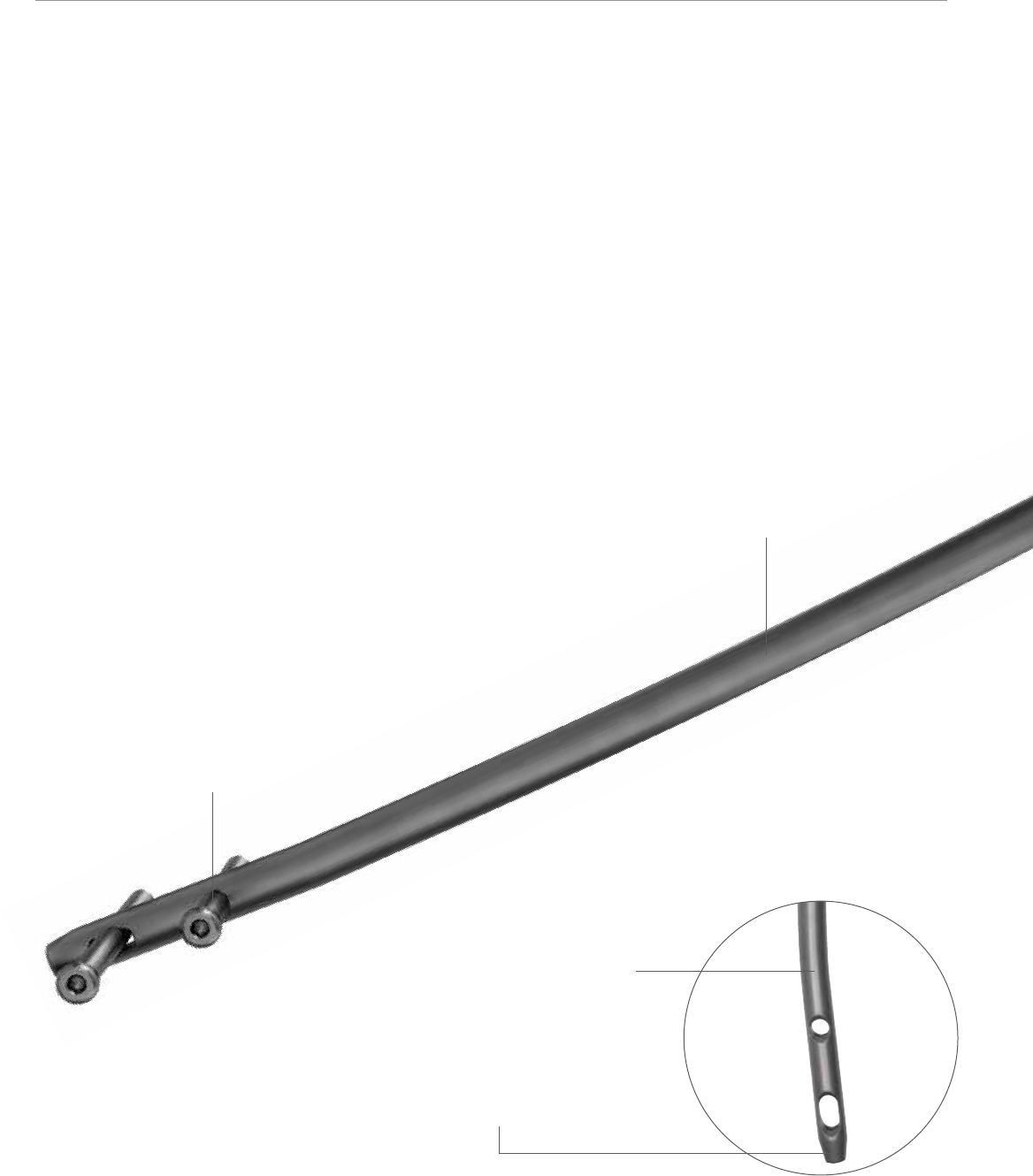
Enlarged nail cannulation accepts the ball nose guide
wire, eliminating the need for an exchange tube.
2.2 meter radius of curvature accommodates
the anterior bow of the femur.
Distal 5° bend (for 9 mm nails) and
3° bend (for 11 mm and 13 mm
nails) facilitate ease of insertion
through the proximal intertrochanteric/
subtrochanteric region.
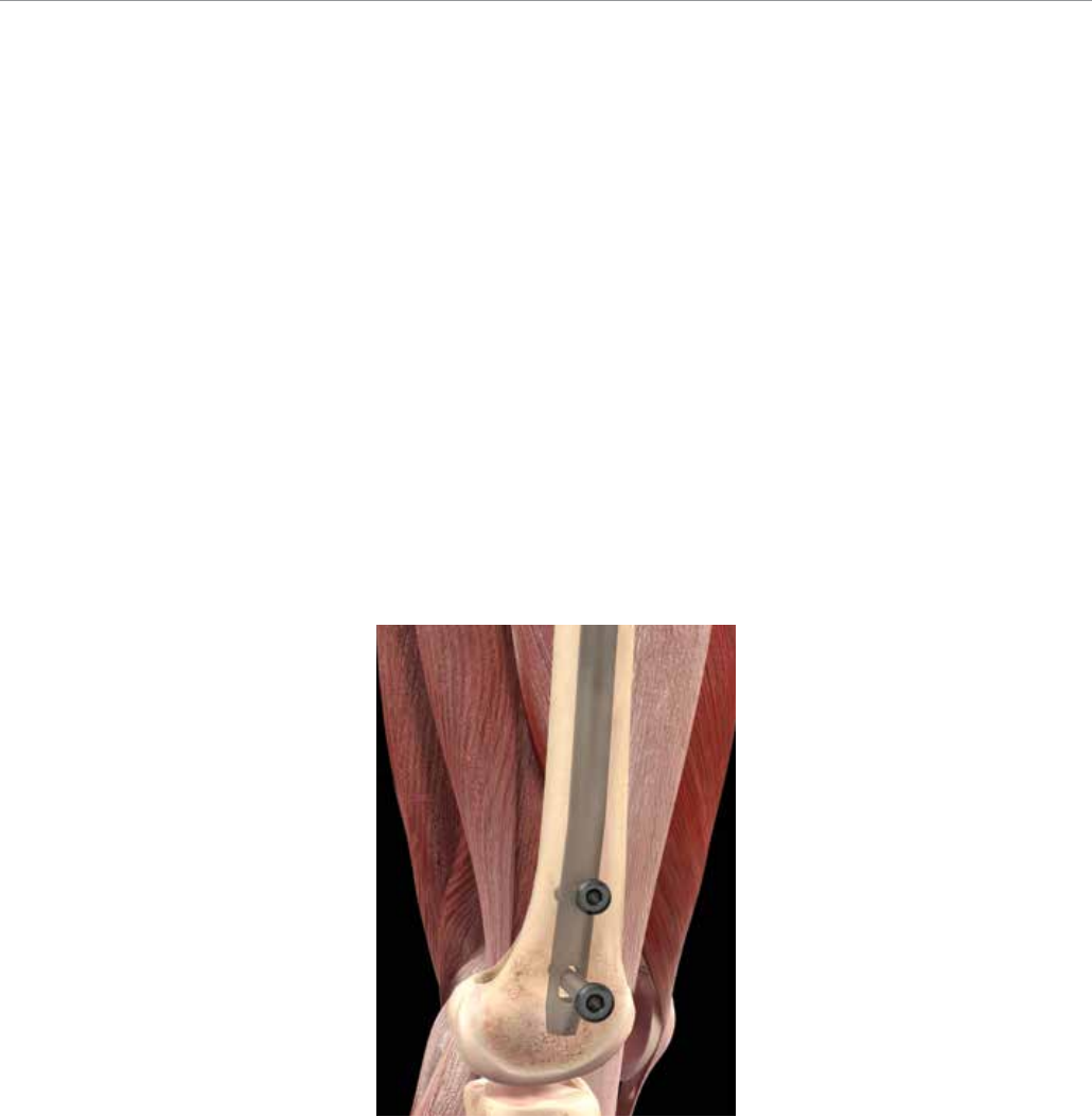
Chamfer on the front of the distal tip
facilitates insertion, and decreases the
risk of anterior cortex penetration in the
distal femur.
4.5 or 5.0 mm distal screw options.
The Troch Entry Nail is intended to treat:
4
VersaNail Femoral Troch Entry Nailing System
6º
125º
45 mm
32 mm
15 mm
18 mm
13 mm
0 mm
5 mm
41 mm
0 mm
22 mm
Distance
Proximal End
13 mm
2.5º Anterior
5º - 9 mm Nail
3º - 11, 13 mm Nails
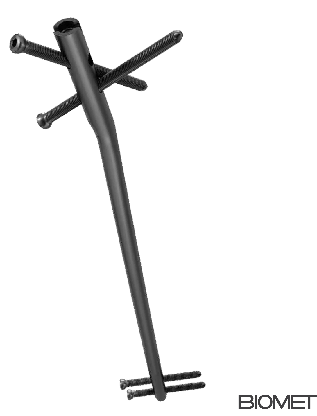
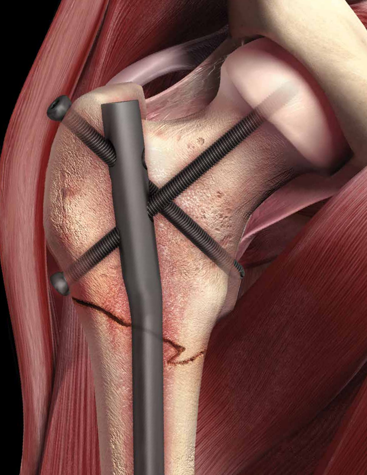
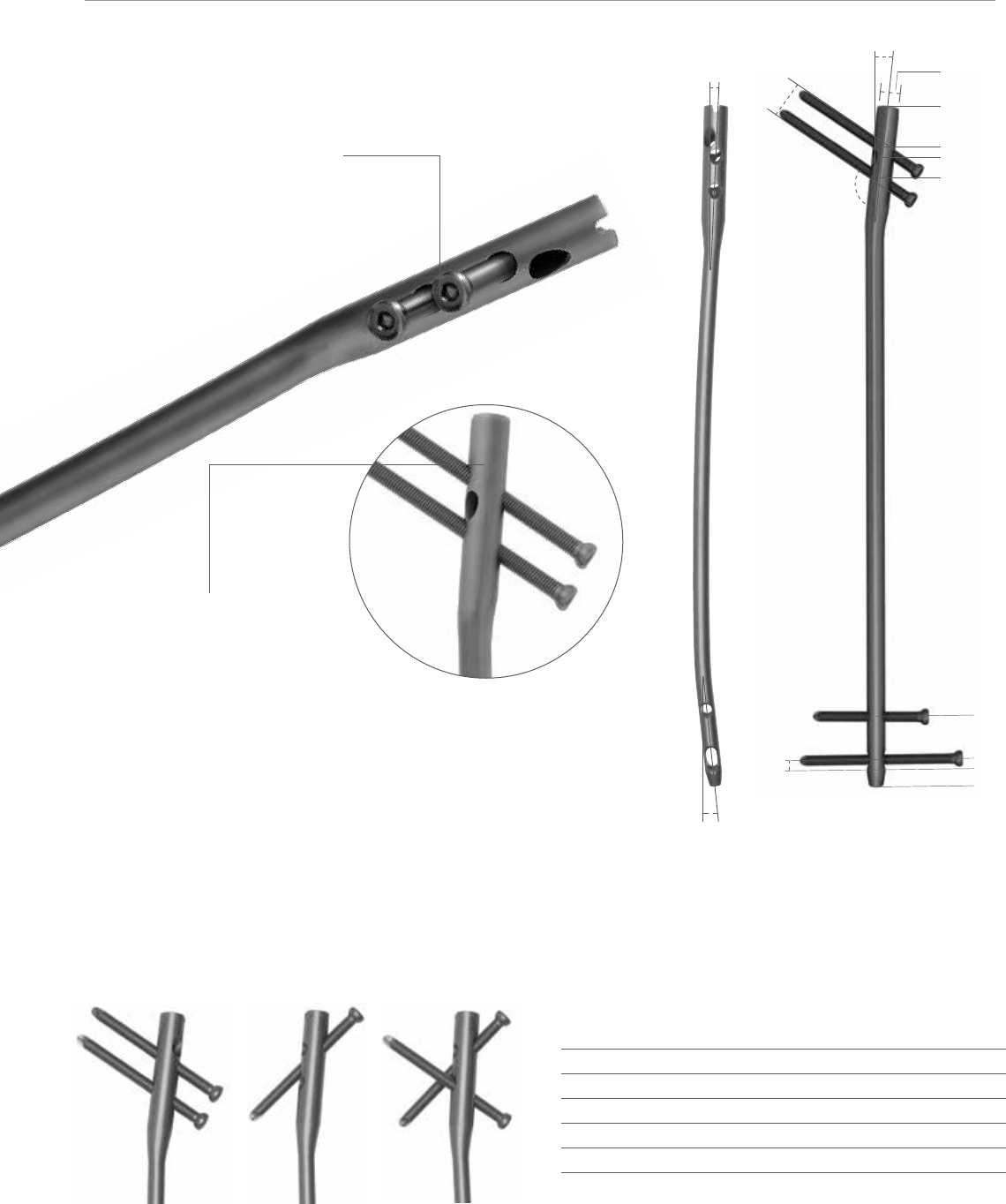
Proximal locking options allow for
two screws into the femoral head or
one screw from the greater to lesser
trochanter.
Unique crosslocking option allows for
one recon screw and one antegrade
screw at the same time, providing
multi-planar fixation.
Large core diameter of the proximal
6.5 mm screws decreases risk for
screw breakage.
125° neck shaft angle facilitates screw
placement into the femoral head.
Proximal 2.5° anterior bend and 6° lateral bend
provide optimal anatomic fit in the proximal femur.
8° of anteversion for anatomic proximal screw.
Multiple locking options for optimum implant stability
The Troch Entry Femoral Nail screw portal configurations provide a number of proximal locking possibilities.
The Troch Entry Nail is locked with 6.5 mm screws proximally and 4.5 or 5.0 mm screws distally.
The locking instrumentation is color-coded for ease of use:
Color Screw Size Drill Bit Size
Black 6.5 mm Cortical 5.3 mm
Gold 6.5 mm Cancellous 6.5 mm/4.8 mm Step Drill
Silver 3.2 mm Guide Pin Sleeve
Green 4.5 mm Cortical 3.8 mm
Green 5.0 mm Cortical 4.3 mm
5
Implant Overview
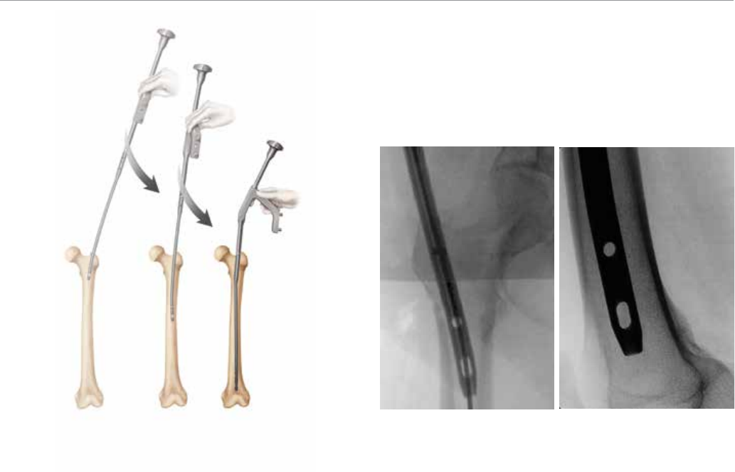
The Troch Entry Femoral Nail incorporates multiple bends
for an excellent anatomic fit. It is designed to facilitate ease
of insertion through the greater trochanter (Figure 1).
Figure 1 Figure 2a Figure 2b
The distal bend, in line with the anterior bow of the nail, is
designed to negotiate the anatomic curve of the greater
trochanteric and subtrochanteric entry into the femoral
canal (Figure 2a).
Once fully seated in the femoral canal, the distal bend
angles posteriorly, reducing potential stress on the anterior
cortex (Figure 2b).
6
VersaNail Femoral Troch Entry Nailing System
Entry and Canal Preparation
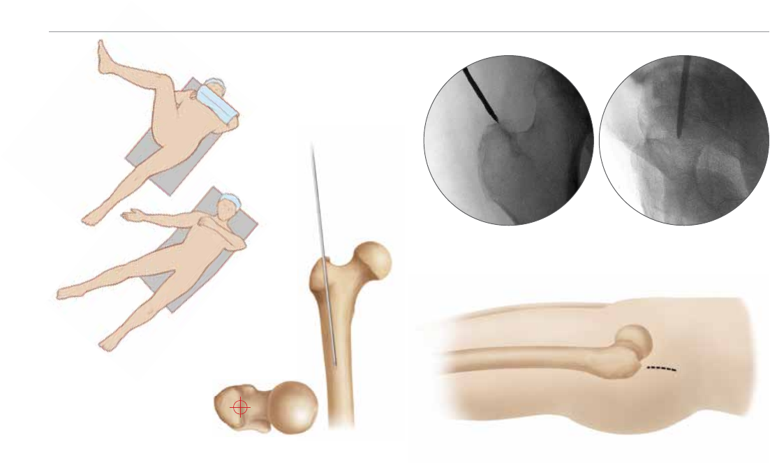
Patient Positioning
Place the patient in the supine or lateral position on either
a fracture or radiolucent imaging table, depending on
surgeon preference. Lateral access to the proximal femur
is required. The affected leg must be abducted and the
trunk secured. The contralateral leg may be flexed at the
hip or scissored below the affected leg (Figure 3).
Surgical Approach and Entry Point
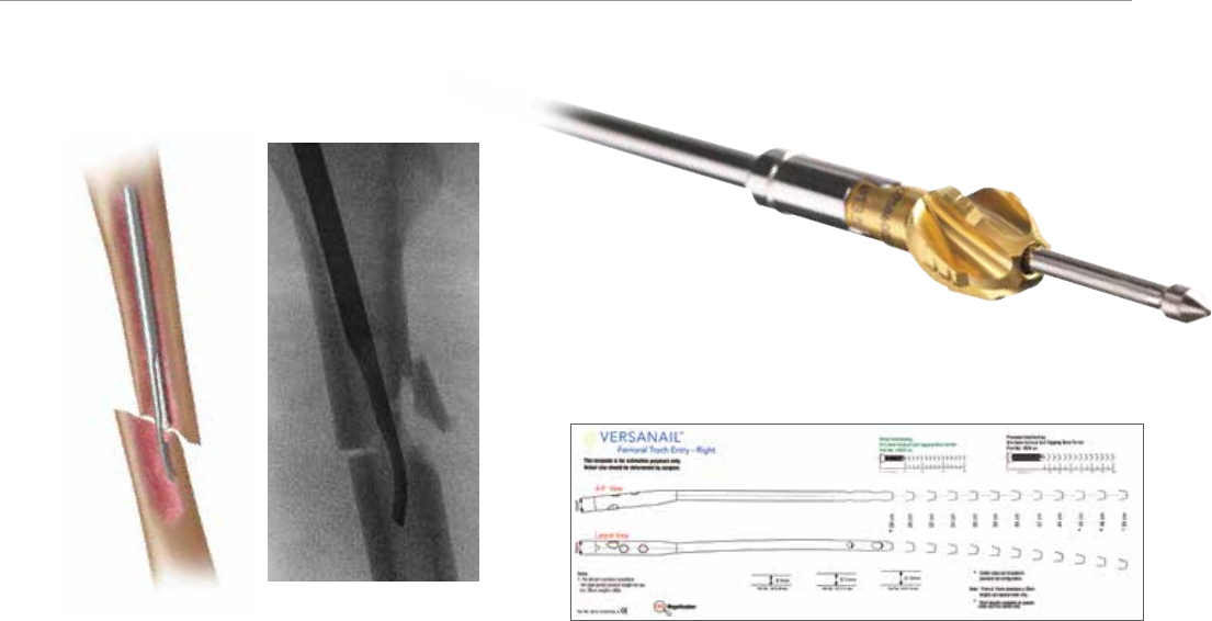
Reference the greater trochanter. Identify the entry site,
which is at the tip of the greater trochanter. Initiate the
entry site with a 3.2 mm guide pin through a stab incision
proximal to the trochanteric region, in line with the femoral
axis (Figure 4).
Figure 3
Figure 4
Figure 5
Figure 6
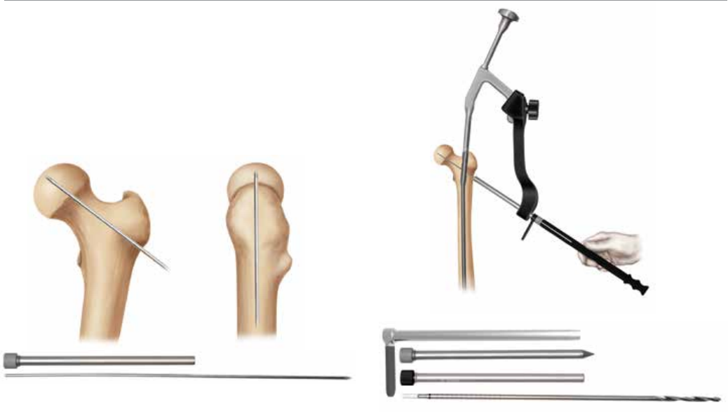
Confirm correct entry location and guide pin placement
radiographically with AP and lateral views. The guide
pin should be in line with the femoral canal in the lateral
view and angled approximately 6 degrees in the AP view.
Care should be taken to ensure that the guide pin and
channel reamer do not migrate laterally, causing varus
malalignment (Figure 5).
Once the ideal entry point has been achieved, extend the
entry incision to 1-2 cm. The fascia lata is divided along its
fibers (Figure 6).
7
The entry portal sleeve and trocar can be advanced over the
guide pin down to the tip of the greater trochanter. Parallel
guide holes allow for accurate adjustment of pin positioning.
(See image for example). Remove the trocar from the entry
portal, keeping the guide pin in place (Figure 7).
Figure 7
Figure 8
Figure 9
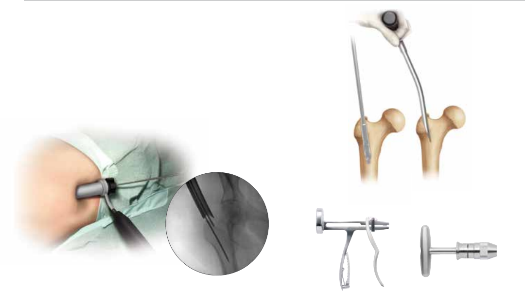
Canal Entry
The entry site can be made using either an entry reamer
or 10.5 mm diameter cannulated awl. Troch Entry Nails
have a proximal diameter of 13 mm which extends 6 cm.
The entry reamers have an enlarged section that matches
the proximal section of the nail. This allows the final depth
of the entry reamer to be visualized fluoroscopically. Both
13 mm and 14 mm entry reamers are available depending
on surgeon preference (Cat. No. 2810-13-002 or 2810-
13-003). An excellent starting hole is especially important
when nailing proximal fracture patterns, those with short
segments and/or medial comminution. Use AP and lateral
fluoroscopic views to confirm accurate placement. Use the
Awl (Cat. No. 2810-01-005) or entry reamer to open the
proximal femur at the greater trochanter. If required, the
Entry Portal Sleeve (Cat. No. 2810-13-005) is available for
soft tissue protection (Figure 8).
Once access to the femoral canal has been gained, place the
ball nose guide wire into the entry site utilizing the guide wire
gripper. Two guide wire gripper styles are available depending
on surgeon preference: the Pistol Grip (Cat. No. 2810-01-
001) or the T-handle Grip (Cat. No. 2810-01-002) (Figure 9).
8
VersaNail Femoral Troch Entry Nailing System
Fracture Reduction
Obtain appropriate anatomic reduction in order to restore
length, anatomic axis alignment and rotation of the injured
limb. Reduction can be achieved through the surgeon’s
preferred method such as traction, external fixator, external
aids or joysticks. To aid in manipulating the fracture
fragments and passing the Ball Nose Guide Wire, large
(7.5 mm diameter, Cat. No. 2810-01-007) and small (6.5
mm diameter, Cat. No. 2810-01-008) reduction tools are
available.
Insert the reduction tool into the medullary canal, past
the fracture site. Once the fracture is in alignment, pass
the Ball Nose Guide Wire, available in both 80 cm (Cat.
No. 2810-01-080) and 100 cm (Cat. No. 2810-01-100)
lengths, across the fracture site. Remove the reduction
tool (Figure 10).
Figure 10
Figure 11
Figure 12
Canal Preparation
Achieve proper alignment of the injured limb prior to
reaming and maintain it throughout the reaming process to
avoid eccentric reaming. Commence reaming by placing
the VERSANAIL flexible reamer over the Biomet ball
nose guide wire (Figure 11). Ream the medullary canal in
millimeter increments until cortical bone is reached and in
half-millimeter increments thereafter. Surgeon preference
should dictate the actual extent of intramedullary reaming.
Monitor the reaming procedure using image intensification
to avoid eccentric or excessive cortical reaming.
An X-ray template is available to determine nail size
preoperatively (Cat. No. 2810-13-033, right, and Cat. No.
2810-13-034, left) (Figure 12).
9

Nail Insertion
Nail Diameter Selection
In general, a nail diameter 1 to 1.5 mm less than the final
reamer diameter is chosen. Troch Entry Nails are available
in 9, 11 and 13 mm diameters.
Nail Length Selection
With the tip of the ball nose guide wire at the level of
the desired depth of nail insertion, slide or snap the Nail
Length Gauge (Cat. No. 2810-01-031) onto the ball nose
guide wire until it contacts the bone, ensuring that the
tip does not fall into the existing trochanteric entry canal,
thus providing an inaccurate measurement. To obtain the
appropriate nail length, read the measurement mark on
the nail length gauge that is closest to the beginning of
the black transition area on the guide wire (Figure 13). If a
nail of the exact measured length is not available, choose
a shorter nail of the next closest available length. A direct
measurement can also be taken of the uninjured extremity
using either radiographs with magnification markers, or
directly on the uninjured limb.
Figure 13 Figure 14
Nail Insertion
The Troch Entry Nail is available in side specific (right
or left) sizes. Ensure that the appropriate nail is chosen
depending on the side of the injury. Place the nail on the
femoral jig in the correct orientation (the proximal lateral
bend should angle toward the jig such that the anterior
bow of the nail corresponds with the anterior bow of the
femur). Secure the nail to the jig by inserting the Jig Bolt
(Cat. No. 2810-13-008) through the cannulation of the jig
nose and tightening with the Flexible Jig Bolt Driver (Cat.
No. 2810-13-037) and T-handle (Cat. No. 2810-01-004).
The flexibility of the jig bolt driver allows 30° of angularity
away from the patients side when removing the targeting
jig from the nail. Check jig alignment with sleeves and drill
bit prior to implanting (Figure 14).
10
VersaNail Femoral Troch Entry Nailing System
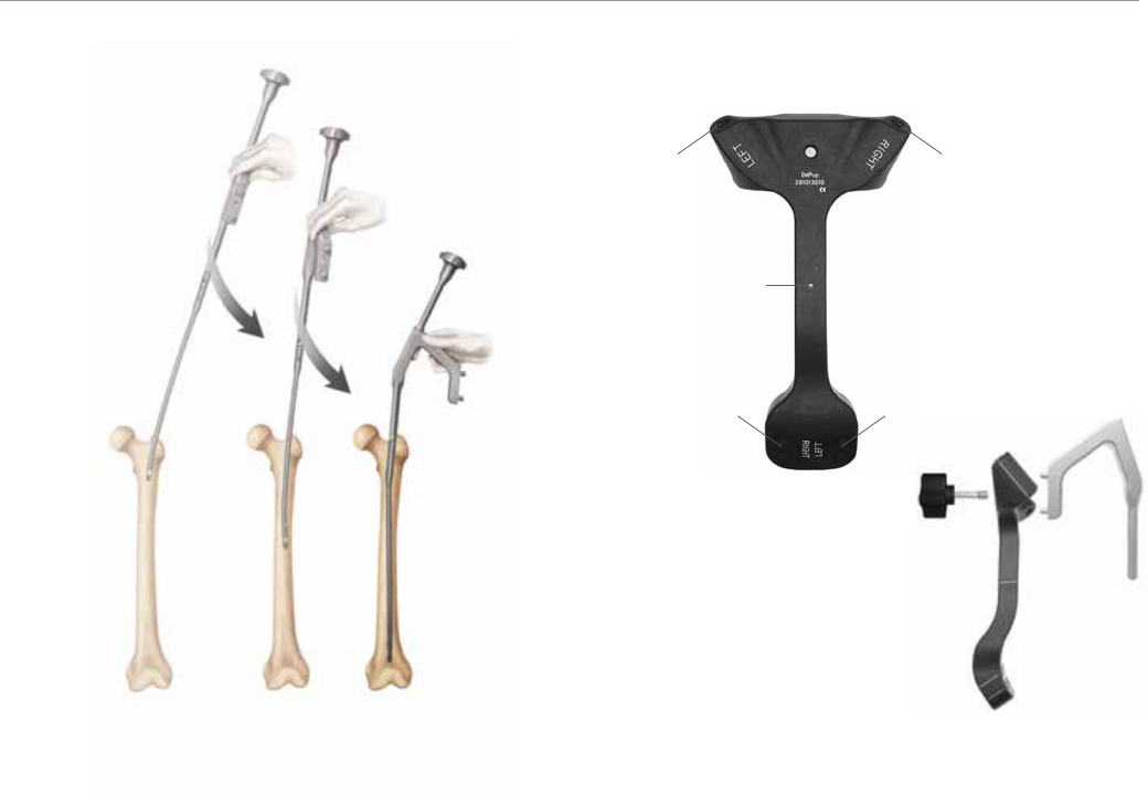
The radiolucent target
arm is etched to
indicate right and left
specific target holes
for antegrade and
recon locking modes
Insert the nail over the 3 mm ball nose guide wire into the
medullary canal. Take care not to strike the jig or targeting
arm with the mallet. Instead use the Hammer Pad (Cat. No.
2810-13-011) with the impaction rod and slotted mallet. It
may be helpful to preliminarily insert the trochanteric nail
utilizing its bow to facilitate clearance of the medial femoral
cortex of the proximal fragment. To do this, rotate the
insertion jig anteriorly (towards the ceiling). In this position
the distal bend in the nail will be angled laterally to aid in
passing the nail through the greater trochanteric entry site,
and avoid medial cortical penetration. As the nail passes
the medial cortex of the proximal fragment, slowly derotate
the jig handle into the usual lateral position, so that the
anterior bow of the nail now corresponds with the anterior
bow of the femur. If the nail requires substantial force to
advance, remove it and ream an additional millimeter.
Avoid excessive force when inserting the nail (Figure
15). Confirm fracture reduction and ensure appropriate
nail insertion depth proximally and distally with biplanar
fluoroscopy. Remove ball nose guide wire.
Figure 15 Figure 16
Right side
antegrade
lock
Left side
antegrade
lock
Guidepin hole
to indicate
nail-jig junction
Right side
recon lock
Left side
recon lock
Locking
Locking
Prior to locking both proximally and distally, adjust traction,
and check femoral length and rotational alignment.
Proximal Locking
Attach the radiolucent targeting arm to the femoral jig and
tighten using the knob on the targeting arm. Ensure that
targeting arm is properly secured to the jig for accurate
targeting. Prior to drilling, check jig position to ensure that
the jig has not externally rotated. The same targeting arm
can be used for both left and right nails and is marked to
identify which locking option is being targeted (Figure 16).
11
It is important to recheck the AP and lateral views of the hip
prior to inserting locking screws directed into the femoral
head. A 3.2 mm x 17.5 in Guide Pin (Cat. No. 9030-
03-004) and guide pin sleeve (Cat. No. 2810-13-018)
are available to check screw positioning prior to drilling
(Figure 17).
Figure 17
Figure 18
Figure 19
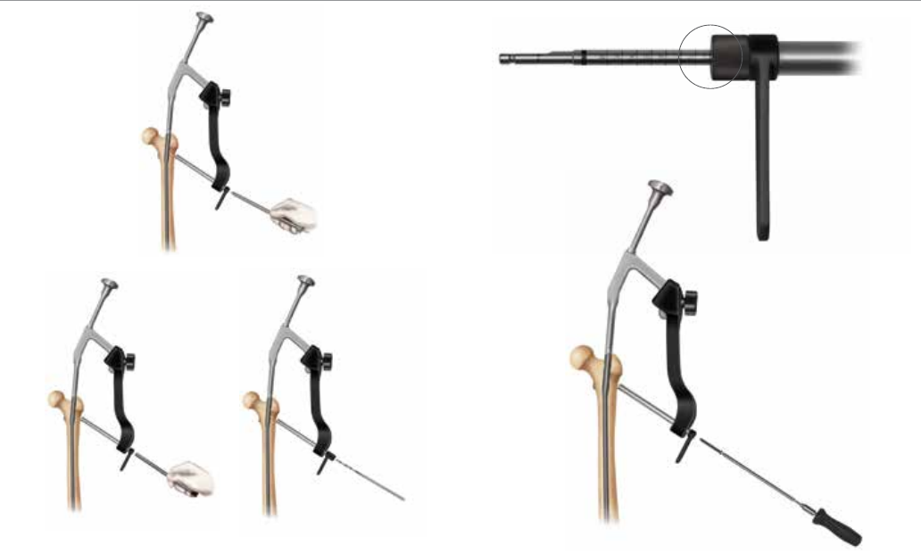
A measurement can be taken from the guide pin using
the 6.5 mm Screw Depth Gauge (Cat. No. 2810-13-035)
(Figure 18).
Place the 6.5 mm proximal locking screws with the locking
instrumentation. The 6.5 mm solid cortical screws are
drilled with a 5.3 mm drill bit. The 5.3 mm drill bit and
corresponding drill sleeve are color-coded black. The 6.5
mm/4.8 mm step drill bit and corresponding drill sleeve are
color-coded gold (Figure 19).
Caution: Utilize fluoroscopy when drilling into the
femoral head so as to not penetrate the subchondral
bone. As noted above, a 3.2 mm x 17.5 in Guide Pin
(Cat. No. 9030-03-004) and Guide Pin Sleeve (Cat. No.
2810-13-018) are available to check screw positioning
prior to drilling.
12
VersaNail Femoral Troch Entry Nailing System
Place the 6.5 mm Screw Sheath (Cat. No. 2810-13-
020) and Trocar (Cat. No. 2810-13-021) through the
appropriate hole in the targeting jig to locate the incision
site. Make a stab incision and advance the sheath and
trocar to the bone (Figure 20).
Remove the trocar and replace it with the 5.3 mm Drill
Sleeve (Cat. No. 2810-13-022). Using the 5.3 mm drill bit
through the drill sleeve, drill until the far cortex is either
reached or penetrated (Figure 21).
Figure 20
Figure 21
Figure 22
Figure 23
Ensure that the drill sleeve is on bone and read the calibration
on the drill bit at the end of the drill sleeve to determine
the appropriate screw length (Figure 22). If penetrating the
far cortex prior to taking the reading, use the screw length
indicated on the drill bit at the screw depth measurement
line. If you are not penetrating the far cortex prior to taking
the reading, add 5 mm in length to the screw length reading.
After selecting the appropriate screw, insert the screw
through the sheath using the screwdriver. The etch mark
on the screwdriver corresponds with the screw sheath to
indicate when the screw is fully seated (Figure 23).
Repeat above steps for additional screw placement.
13
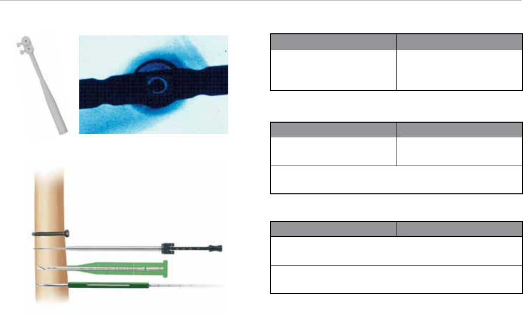
Figure 25
Figure 24
Distal Locking
Prior to locking distal screws check femoral length
and rotation under fluoroscopy. Distal locking should
be conducted using the standard image intensification
freehand technique. A white Radiolucent Targeting Wand
(Cat. No. 1201) is available if desired (Figure 24).
Either a 4.5 mm or 5.0 mm distal screw may be utilized.
Using the drill bit that corresponds to the screw diameter
of choice, drill until the far cortex is either reached or
penetrated. Verify the drill bit position fluoroscopically prior
to taking any measurements (Figure 25).
A Screw Depth Gauge (Cat. No. 2810-01-017) is provided
to determine the screw length for either a 4.5 mm or
5.0 mm screw. The following alternative distal screw
measurement techniques are also available depending on
which diameter screw is utilized:
Distal Screw Drill Options
4.5 mm Screw 5.0 mm Screw
3.8 mm Drill Bit
Cat. No. 2810-121-38 (6 in.)
Cat. No. 2810-131-38 (8 in.)
4.3 mm Short
Graduated Drill
Cat. No. 2112-014-06
Distal Screw Depth Gauge Options
4.5 mm Screw 5.0 mm Screw
Screw Length Gauge
Cat. No. 2810-010-32
Drill Measuring Sleeve
Cat. No. 2112-014-10
Screw Depth Gauge
Cat. No. 2810-010-17
Distal Screw Driver Options
4.5 mm Screw 5.0 mm Screw
4.5/5.5 mm Screwdriver Shaft
Cat. No. 2810-010-15
SolidLok Screwdriver
Cat. No. 2810-010-19, 2810-010-20, 2810-010-21
If using a 4.5 mm screw: Place the green 4.5 mm Screw
Length Gauge (Cat. No. 2810-010-32) onto the calibrated
drill bit (Cat. No. 2810-121-38 or 2810-131-38) and
advance down to the bone. Read the calibration on the
drill bit that corresponds to the measurement line indicated
on the Screw Length Gauge.
If using a 5.0 mm screw: Use the short 4.3 mm graduated
drill (Cat. No. 2112-014-06) and the 4.3 mm drill measuring
sleeve (Cat. No. 2112-014-10). Read the calibration directly
off of the 4.3 mm graduated drill by using the drill measuring
sleeve. The measurement should be taken from the end of
the measuring sleeve that is closest to the power source.
To ensure an accurate reading, each screw measuring tool
should be fully seated on bone. The use of fluoroscopy is
recommended to verify the correct screw length. Remove
the drill bit and advance either the 4.5 mm or 5.0mm
screw using the SolidLok Screwdriver (Cat. No. 2810-
010-19, 2810-010-20, 2810-010-21) or screwdriver shaft
(Cat. No. 2810-010-15). Repeat above steps for additional
screw placement.
14
VersaNail Femoral Troch Entry Nailing System
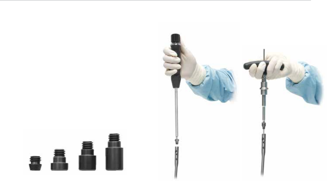
End Cap Placement
End Cap Placement
Cannulated end caps are provided in the system to both
prevent bony ingrowth and add length when needed
(Figure 26).
End caps have a double hex of 5 mm and 3.5 mm and are
cannulated to accept a 3.2 mm guide pin.
Figure 26 Figure 27
Place the end cap into the end of the nail with the 4.5 mm
screwdriver. If the end cap will be placed using a 3.2 mm
Guide Pin (Cat. No. 14012-14), place the end cap with the
5 mm Jig Bolt Driver (Cat. No. 2810-01-011).
A non-cannulated locking screwdriver is also available to
aid in end cap placement (Figure 27). Irrigate the wound
and perform a layered closure in the usual fashion.
15
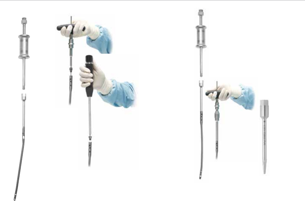
Nail Removal
If the surgeon deems it appropriate to remove the nail, a
Cannulated Extractor Bolt (Cat. No. 2810-01-023), used
with a 3/4 in Hex Driver (Cat. No. 2810-01-027) and a
T-handle Hudson (Cat. No. 2810-01-004), is provided to
aid in nail extraction (Figure 28).
Locate the top of the nail through an appropriate incision.
Remove the end cap. End caps have a double hex of 5
mm and 3.5 mm and are cannulated to accept a 3.2 mm
guide pin. Insert the 3.2 mm guide pin and remove the end
cap using the Cannulated Jig Bolt Driver (Cat. No. 2810-
01-011) (Figure 29).
The SolidLok Locking Screwdriver (Cat. No. 2810-01-
020 and Cat. No. 2810-01-021) is also available to aid
in removing the end cap. Insert the SolidLok screwdriver
into the Hex Tip (Cat. No. 2810-01-019) and tighten the
handle to lock the end cap’s hex tip into the inner end
cap’s 3.5 mm hex. The end cap can also be removed with
a standard 3.5 mm hex screwdriver.
Figure 29
Figure 30
Figure 28
Figure 31
Make the appropriate incisions and remove all locking
screws. Remove all overgrown bone around the nail’s
proximal aspect to avoid iatrogenic fracture during nail
extraction. Once the locking screws have been removed,
drive a 3.2 mm guide pin into the cannulation in the nail’s
proximal section. Insert the extractor bolt over the 3.2
mm guide pin and thread it into the nail. Ensure that the
extractor is fully threaded into the nail prior to extraction.
Then thread the impactor rod into the extractor bolt and
use either the slotted mallet or sliding hammer to remove
the nail (Figure 30). During nail removal it may be helpful to
gently counter-rotate the nail as it is being extracted such
that the distal and anterior nail contours rotate laterally to
aid in removing the nail through the proximal portion of the
femur and trochanteric entry portal.
A Conical Nail Extractor Bolt (Cat. No. 2810-01-022) is
also available for removal in cases where the nail threads
are difficult to engage (Figure 31). This instrument is
designed to work with various nail thread/cannulation
designs.
Note: Nail thread/cannulation condition may limit the
purchase amount that can be gained using the conical
extractor bolt.
16
VersaNail Femoral Troch Entry Nailing System

Ordering Information
Cat. No. Rights Cat. No. Lefts Description
Femoral Troch Entry Nail 9 mm 28-50 cm
1814-09-280 1815-09-280 9 mm x 28 cm
1814-09-300 1815-09-300 9 mm x 30 cm
1814-09-320 1815-09-320 9 mm x 32 cm
1814-09-340 1815-09-340 9 mm x 34 cm
1814-09-360 1815-09-360 9 mm x 36 cm
1814-09-380 1815-09-380 9 mm x 38 cm
1814-09-400 1815-09-400 9 mm x 40 cm
1814-09-420 1815-09-420 9 mm x 42 cm
1814-09-440 1815-09-440 9 mm x 44 cm
1814-09-460 1815-09-460 9 mm x 46 cm
1814-09-480 1815-09-480 9 mm x 48 cm
1814-09-500 1815-09-500 9 mm x 50 cm
Femoral Troch Entry Nail 11 mm 28-50 cm
1814-11-280 1815-11-280 11 mm x 28 cm
1814-11-300 1815-11-300 11 mm x 30 cm
1814-11-320 1815-11-320 11 mm x 32 cm
1814-11-340 1815-11-340 11 mm x 34 cm
1814-11-360 1815-11-360 11 mm x 36 cm
1814-11-380 1815-11-380 11 mm x 38 cm
1814-11-400 1815-11-400 11 mm x 40 cm
1814-11-420 1815-11-420 11 mm x 42 cm
1814-11-440 1815-11-440 11 mm x 44 cm
1814-11-460 1815-11-460 11 mm x 46 cm
1814-11-480 1815-11-480 11 mm x 48 cm
1814-11-500 1815-11-500 11 mm x 50 cm
Femoral Troch Entry Nail 13 mm 28-50 cm
1814-13-280 1815-13-280 13 mm x 28 cm
1814-13-300 1815-13-300 13 mm x 30 cm
1814-13-320 1815-13-320 13 mm x 32 cm
1814-13-340 1815-13-340 13 mm x 34 cm
1814-13-360 1815-13-360 13 mm x 36 cm
1814-13-380 1815-13-380 13 mm x 38 cm
1814-13-400 1815-13-400 13 mm x 40 cm
1814-13-420 1815-13-420 13 mm x 42 cm
1814-13-440 1815-13-440 13 mm x 44 cm
1814-13-460 1815-13-460 13 mm x 46 cm
1814-13-480 1815-13-480 13 mm x 48 cm
1814-13-500 1815-13-500 13 mm x 50 cm
End Caps
1813-00-001 End Cap Universal Flush
1813-00-005 End Cap Universal 5 mm
1813-00-010 End Cap Universal 10 mm
1813-00-015 End Cap Universal 15 mm
6.5 mm Self Tapping Cortical Screws Full Thread (Proximal)
1020-40 40 mm Length
1020-45 45 mm Length
1020-50 50 mm Length
1020-55 55 mm Length
1020-60 60 mm Length
1020-65 65 mm Length
1020-70 70 mm Length
1020-75 75 mm Length
1020-80 80 mm Length
1020-85 85 mm Length
1020-90 90 mm Length
Indicates outlier size not included in standard set configuration.
Indicates special orders only. Not an inventory item. Packaged
non-sterile only.
Sterile packaged.
1020-95 95 mm Length
1020-100 100 mm Length
8050-65-105 105 mm Length
8050-65-110 110 mm Length
8050-65-115 115 mm Length
8050-65-120 120 mm Length
4.5 mm Self Tapping Cortical Screws Full Thread (Distal)
14022-24 24 mm Length
14022-28 28 mm Length
14022-32 32 mm Length
14022-36 36 mm Length
14022-40 40 mm Length
14022-44 44 mm Length
14022-48 48 mm Length
14022-52 52 mm Length
14022-56 56 mm Length
14022-60 60 mm Length
14022-65 65 mm Length
14022-70 70 mm Length
14022-75 75 mm Length
14022-80 80 mm Length
4.5 mm screws available in 2 mm increments up to 60 mm.
5.0 mm Self Tapping Cortical Screws Full Thread (Distal)
8145-50-020 20 mm Length
8145-50-022 22 mm Length
8145-50-024 24 mm Length
8145-50-026 26 mm Length
8145-50-028 28 mm Length
8145-50-030 30 mm Length
8145-50-032 32 mm Length
8145-50-034 34 mm Length
8145-50-036 36 mm Length
8145-50-038 38 mm Length
8145-50-040 40 mm Length
8145-50-042 42 mm Length
8145-50-044 44 mm Length
8145-50-046 46 mm Length
8145-50-048 48 mm Length
8145-50-050 50 mm Length
8145-50-052 52 mm Length
8145-50-054 54 mm Length
8145-50-056 56 mm Length
8145-50-058 58 mm Length
8145-50-060 60 mm Length
8145-50-065 65 mm Length
8145-50-070 70 mm Length
8145-50-075 75 mm Length
8145-50-080 80 mm Length
Cat. No. Description
17
1
2
9
10
8
7
13
14
15
16
17
21
22
5
6
11
12
3
4
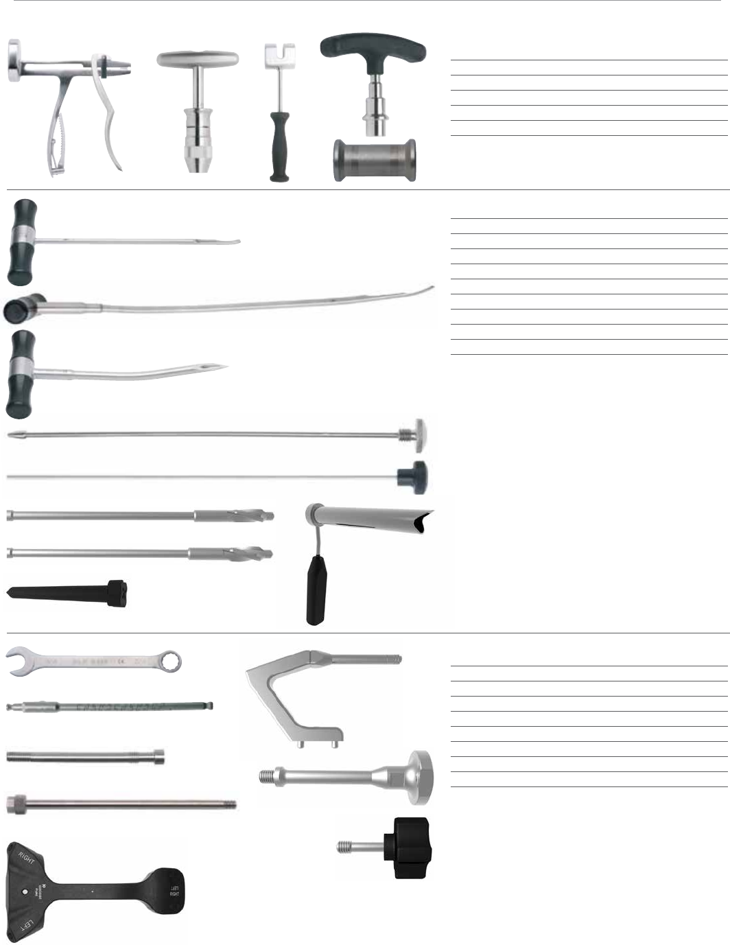
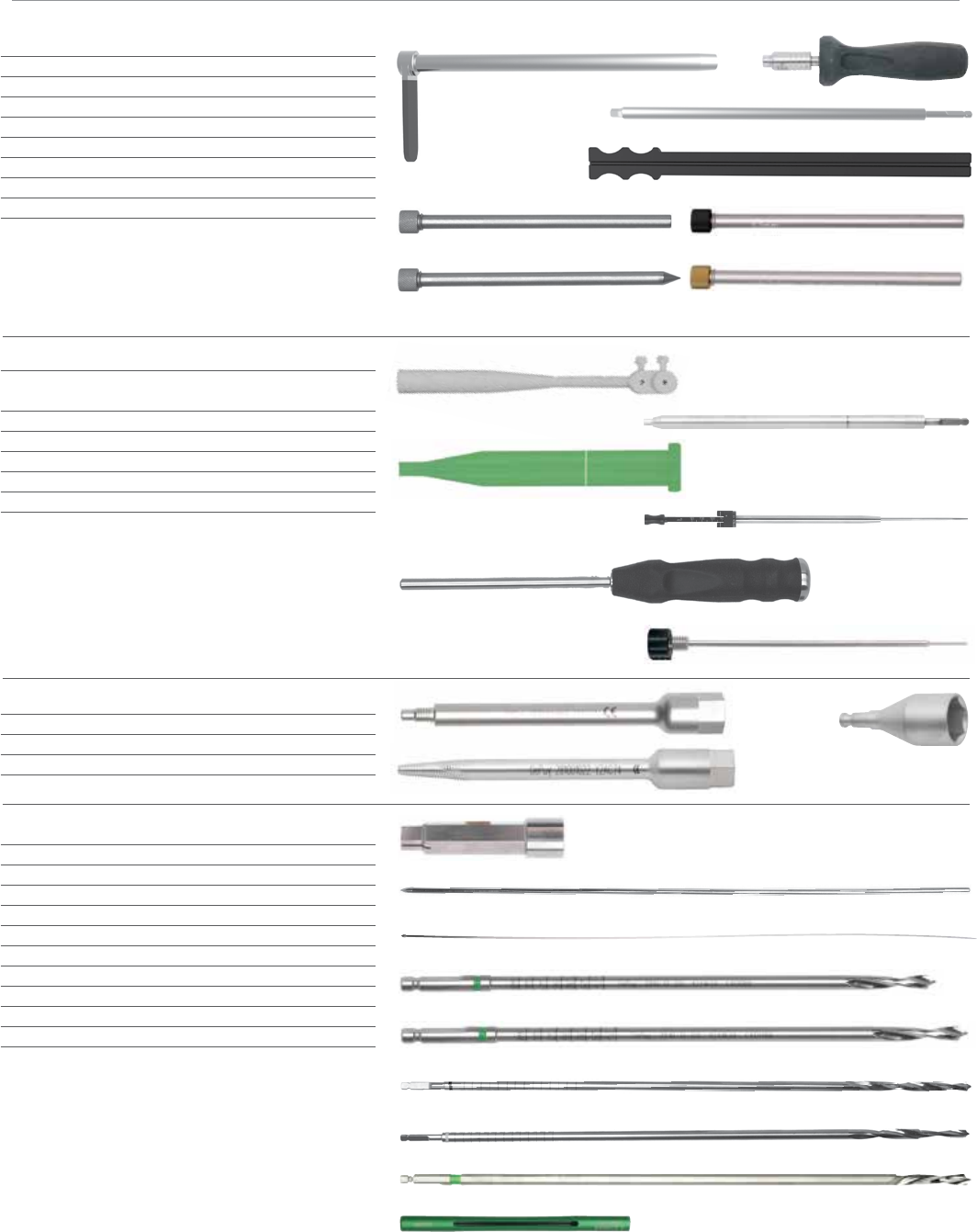
General
2810-01-001 Pistol Guidewire Gripper 1
2810-01-002 T-Handle Guidewire Gripper (optional) 2
2810-01-003 Slotted Mallet 3
2810-01-004 T-Handle Hudson 4
1096 Sliding Hammer 5
Canal Prep
2810-01-008 Short Reduction Tool 6
2810-01-007 Long Reduction Tool 7
2810-01-005 Curved Cannulated Awl 8
2810-01-025 Awl Stylus 9
2810-01-026 Guidewire Pusher 10
2810-13-002 13 mm Entry Reamer, Femur 11
2810-13-003 14 mm Entry Reamer, Femur 12
2810-13-004 Entry Portal Trocar 13
2810-13-005 Long Entry Portal 14
Nail Insertion
1186 3/4 in. Combination Wrench 15
2810-13-037 Flexible Jig Bolt Driver 16
2810-13-008 Femoral Jig Bolt 17
1095 Impactor Rod/Extraction 18
2810-13-010 Troch Entry Target Arm 19
2810-13-007 Femoral Insertion Handle 20
2810-13-011 Hammer Pad Femur 21
2810-13-026 Target Arm Attachment Bolt 22
20
19
18
18
VersaNail Femoral Troch Entry Nailing System
34
35
36
Proximal Locking
2810-13-020 6.5 mm Screw Sheath 23
2810-13-018 3.2 mm Guide Pin Sleeve - Silver 24
2810-13-021 6.5 mm Screw Trocar 25
2810-13-022 5.3 mm Drill Sleeve - Black 26
2810-13-023 6.5/4.8 mm Step Drill Sleeve - Gold 27
2141-49-000 AO Quick Couple Screwdriver 28
2810-13-024 6.5 mm Screwdriver Shaft 29
2810-13-035 6.5 mm Screw Depth Gauge 30
Distal Locking
1201 Freehand Distal Targ. Dev.
Troch Entry - White 31
2810-01-032 4.5 mm Screw Length Gauge 32
2810-01-020 SolidLok Screwdriver Handle 33
2810-01-015 4.5/5.5 mm Screwdriver Shaft 34
2810-01-017 Screw Depth Gauge 35
2810-01-021 SolidLok Driver Inner Shaft 36
Nail Removal
2810-01-023 Extractor Bolt, Tibia/Femur 37
2810-01-022 Conical Extractor Tool 38
2810-01-027 3/4 in Hex Driver 39
Disposables
14012-14 3.2 mm x 14 in Short Threaded Guide Pin
2810-01-019 SolidLok Hex Tip, 3.5 mm 40
9030-03-004 3.2 mm x 17 1/2 in Threaded Guide Pin 41
2810-01-100 Ball Nose Guide Wire 100 cm 42
2810-12-138 3.8 mm Drill Bit 6 in, Non-sterile 43
2810-13-138 3.8 mm Drill Bit 8 in, Non-sterile 44
2810-13-153 5.3 mm Drill Bit, Non-sterile 45
2810-13-165 6.5/4.8 mm Step Drill Bit, Non-sterile 46
2112-01-406 4.3 mm Distal Graduated Drill Short 47
2112-01-410 4.3 mm Drill Measuring Sleeve 48
37
38
39
44
42
23
31
32
28
29
30
33
45
46
47
48
43
40
26
27
24
25
41
19
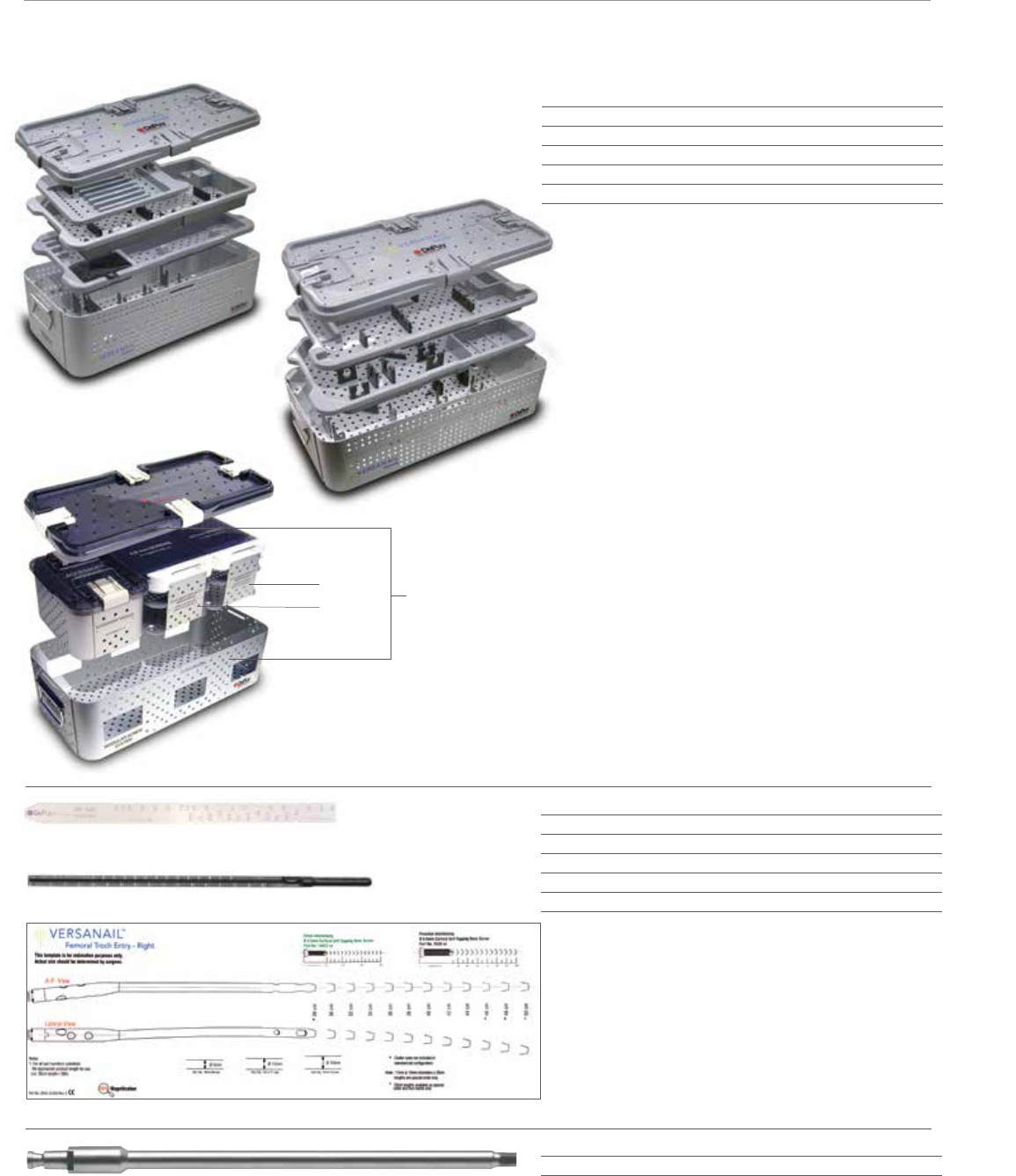
52
53
54
55
50
51 49 Outer Case
48
Nail Measurement
1245 Radiographic Ruler 52
2810-01-031 Nail Length Gauge, 14 mm 53
2810-13-033 VERSANAIL Troch Entry Template - Right 54
2810-13-034 VERSANAIL Troch Entry Template - Left 54
1815-99-380 TEN Femoral DNI 11 mm x 38 cm
Endcap Placement
2810-01-037 5.0 mm Hex Driver, Long 55
47
Cases & Trays
2810-13-030 Femoral Tray Entry & Jigs 47
2810-13-031 Femoral Tray Locking & Extraction 48
8299-10-500 Modular Screw System Outer Case 49
8299-10-065 6.5 mm Screw Module 50
8299-10-045 4.5 mm Cort Screw Module 51
20
VersaNail Femoral Troch Entry Nailing System
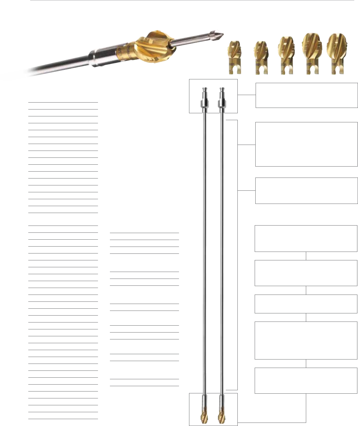
Monobloc Reamer Hud-
son
Cat. No. Diameter
2810-02-060 6.0 mm
2810-02-065 6.5 mm
2810-02-070 7.0 mm
2810-02-075 7.5 mm
2810-02-080 8.0 mm
2810-02-085 8.5 mm
2810-02-090 9.0 mm
2810-02-095 9.5 mm
2810-02-100 10.0 mm
2810-02-105 10.5 mm
2810-02-110 11.0 mm
2810-02-115 11.5 mm
2810-02-120 12.0 mm
2810-02-125 12.5 mm
2810-02-130 13.0 mm
Modular Reamer Head
Cat. No. Diameter
2810-04-090 9.0 mm
2810-04-095 9.5 mm
2810-04-100 10.0 mm
2810-04-105 10.5 mm
2810-04-110 11.0 mm
2810-04-115 11.5 mm
2810-04-120 12.0 mm
2810-04-125 12.5 mm
2810-04-130 13.0 mm
2810-04-135 13.5 mm
2810-04-140 14.0 mm
2810-04-145 14.5 mm
2810-04-150 15.0 mm
2810-04-155 15.5 mm
2810-04-160 16.0 mm
2810-04-165 16.5 mm
2810-04-170 17.0 mm
2810-04-175 17.5 mm
2810-04-180 18.0 mm
2810-04-185 18.5 mm
2810-04-190 19.0 mm
2810-04-195 19.5 mm
2810-04-200 20.0 mm
2810-04-205 20.5 mm
2810-04-210 21.0 mm
2810-04-215 21.5 mm
2810-04-220 22.0 mm
Nitinol Modular
Reamer Shaft Hudson
Cat. No. Length
2810-02-400 400 mm
2810-02-470 470 mm
Reamer Extension
Cat. No. Length
2810-02-015 150 mm
Ball Nose Guide Wires
Cat. No. Length
3.0 mm
(use with 8.0-22.0 mm Reamers)
2810-01-080 800 mm
2810-01-100 1000 mm
2.0 mm
(use with 6.0-7.5 mm Reamers)
2810-17-006 700 mm
Flexible Reamer Case
2810-02-016
Flexible Reaming System
Small shaft diameters allow debris to be removed
and transported up to the open proximal end of
the medullary canal.
Excellent cleanability - Nitinol (Nickel-Titanium)
alloy allows for a smooth cannulated shaft that
provides the required flexibility without the cleaning
problems associated with coil-cut or spring shaft
designs.
Deep cutting flutes allow debris to be moved
proximally away from the reamer head,
maintaining cutting edge efficiency.
Sharp side cutting edges are designed to remove
bone without generating a substantial increase in
temperature.
Surface coating titanium nitride (TiNi) will keep
cutting edge sharper longer.
Ellipsoidal head shape allows the cutting edge to
remove bone gradually and transport debris away,
while bone chipping design decreases the size of
debris, reducing canal pressure.
Reverse cutting feature minimizes the potential for
the reamer to catch in the medullary canal.
Coupling design is simple, long established and
easy to clean (AO and/or HUDSON).
21
Important:
This Essential Product Information does not include all of the information necessary for
selection and use of a device. Please see full labeling for all necessary information.
The use of metallic surgical appliances (screws, plates, intramedullary nails,
compression hip screw, pins and wires) provies the orthopaedic surgeon and
reconstructive surgeries. these implants are intended as a guide to normal healing,
and are NOT intended to replace normal body structure or bear the weight of the
body in the presence of incomplete bone healing. Delayed unions or nonunions in the
presence of load bearing or weight bearing might eventually cause the implant to break
due to metal fatigue. All metal surgical implants are subjected to repeated stress in
use, which can result in metal fatigue.
Indications:
The VersaNail Femoral Troch entry is indicated to treat proximal, middle and distal
third fractures, severely comminuted shaft fractures extending beyond the isthmus,
spiral, long oblique and segmental fractures, non-unions and malunions, lengthening
of the bone, fractures with bone loss, bi-lateral fractures, pseudoarthrosis of the
femoral shaft, supracondylar fractures, subtrochanteric fractures, with or without
involvement of lesser trochanter, subtrochanteric/intertrochanteric combination
fractures, ipsilateral femoral shaft and neck fractures, stable and unstable proximal
fractures of the femur, including pertrochanteric fractures, intertrochanteric fractures,
high subtrochanteric fractures and combinations of these fractures, pertrochanteric
fractures associated with shaft fractures, pathologic fractures in osteoporotic bone of
the trochanteric and diaphyseal areas, proximal or distal non-unions and malunions,
leg length discrepancies secondary to femoral inequality, femur reconstruction
following tumor resection, stable femoral fractures without necessity for interlocking,
long subtrochanteric fractures, and revision procedures involving the replacement of
implanted hardware.
Contraindications:
Screws, plates, intramedullary nails, compression hip screws, pins and wires are
contraindicated in: active infection, conditions which tend to retard healing such as
blood supply limitations, previous infections, insufficient quantity or quality of bone to
permit stabilization of the fracture complex, conditions that restrict the patient’s ability
or willingness to follow postoperative instructions during the healing process, foreign
body sensitivity, and cases where the implant(s) would cross open epiphyseal plates in
skeletally immature patients.
Additional Contraindication for Retrograde Femoral Nailing:
A history of septic arthritis of the knee and knee extension contracture with inability to
attain at least 45º of flexion.
Adverse Events:
The following are the most frequent adverse events after fixation with orthopaedic
screws, plates, intramedullary nails, compression hip screws, pins and wires:
loosening, bending, cracking or fracture of the components or loss of fixation in bone
attributable to nonunion, osteoporosis, markedly unstable comminuted fractures; loss
of anatomic position with nonunion or malunion with rotation or angulation; infection
and allergies and adverse reactions to the device material. Surgeons should take
care when targeting and drilling for the proximal screws in any tibial nail with oblique
proximal screws. Care should be taken as the drill bit is advanced to penetrate the far
cortex. Advancing the drill bit too far in this area may cause injury to the deep peroneal
nerve. Fluoroscopy should be used to verify correct positioning of the drill bit.
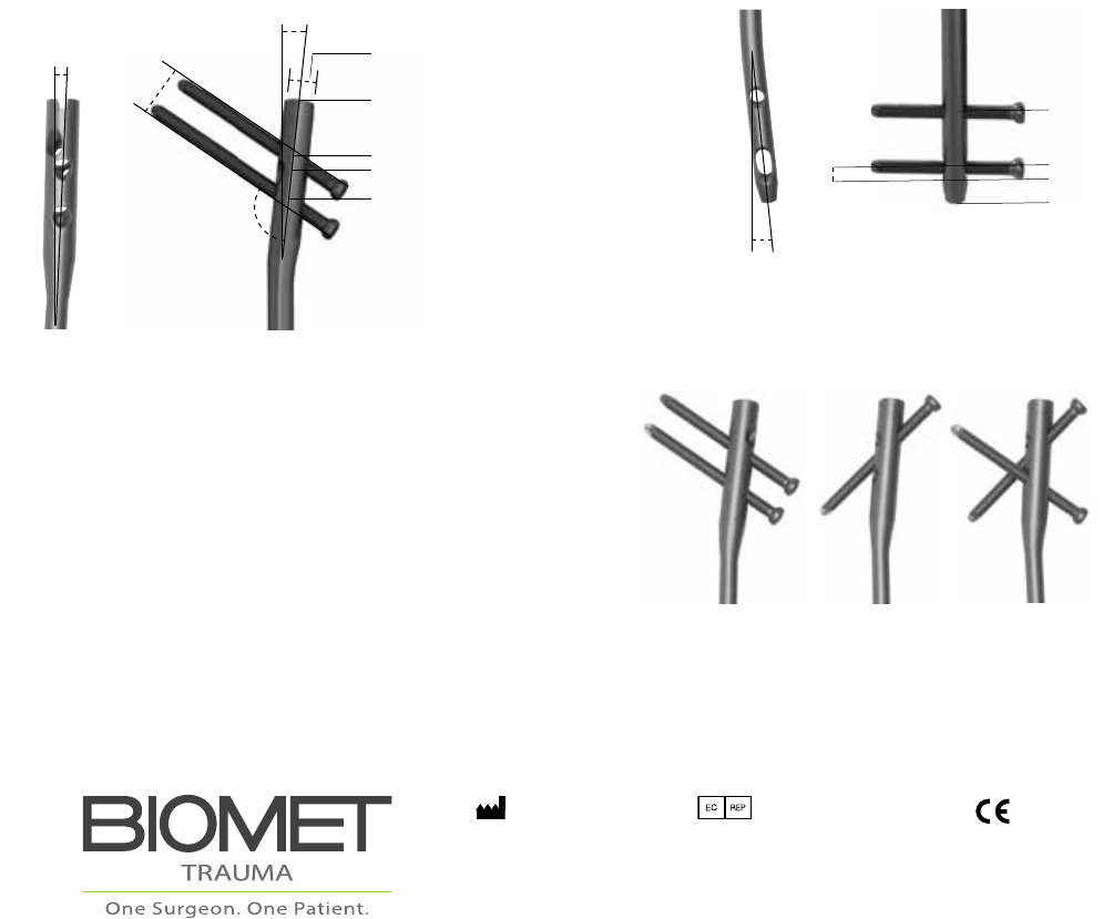
Proximal End Distal End
Locking Options
5º - 9 mm Nail
3º - 11, 13 mm Nails
6º Lateral
125º
45 mm
15 mm
32 mm
0 mm
22 mm
Distance
Proximal End
13 mm
2.5º Anterior
18 mm
13 mm
0 mm
41 mm
5 mm
This material is intended for health care professionals and the Biomet sales
force only. Distribution to any other recipient is prohibited. All content here in is
protected by copyright, trademarks and other intellectual property rights owned
by or licensed to Biomet Inc. or its aliates unless otherwise indicated. This material
must not be redistributed, duplicated or disclosed, in whole or in part, without the
express written consent of Biomet.
Check for country product clearances and reference product specic instructions
for use. For complete product information, including indications, contraindications,
warnings, precautions, and potential adverse eects, see the package insert and
Biomet’s website.
This technique was prepared in conjunction with a licensed health care professional.
Biomet does not practice medicine and does not recommend any particular
orthopedic implant or surgical technique for use on a specic patient. The surgeon
is responsible for determining the appropriate device(s) and technique(s) for each
individual patient.
Not for distribution in France.
©2014 Biomet Trauma • Form No. BMET0032.0-GBL • REV0714
Legal Manufacturer
Biomet Trauma
56 East Bell Drive
P.O. Box 587
Warsaw, Indiana 46581
USA
www.biomet.com
Authorised Representative
Biomet UK Ltd.
Waterton Industrial Estate
Bridgend, South Wales
CF31 3XA
UK
0086
