System Manual Servo Drives AX5000 Ftp://ftp.beckhoff.com//motion/ax5000_system_manual_hw2_en Hw2 En
User Manual: Pdf ftp://ftp.beckhoff.com//motion/ax5000_system_manual_hw2_en manual pdf
Open the PDF directly: View PDF ![]() .
.
Page Count: 266 [warning: Documents this large are best viewed by clicking the View PDF Link!]
- 1 Documented servo drives
- Table of contents
- 2 Foreword
- 3 Guidelines and Standards
- 4 Safety
- 5 Handling
- 6 Product overview
- 7 Technical description
- 7.1 Configuration of the servo drives
- 7.2 General technical data
- 7.2.1 Permissible ambient and operating conditions
- 7.2.2 Electrical data - servo drive (AX5101 - AX5140)
- 7.2.3 Electrical data - servo drive (AX52xx)
- 7.2.4 Electrical data - servo drive (AX5160 - AX5193)
- 7.2.5 Mechanical data - servo drive (AX5101-AX5140)
- 7.2.6 Mechanical data - servo drive (AX52xx)
- 7.2.7 Mechanical data - servo drive (AX5160 - AX5193)
- 7.3 Dimensions
- 7.4 Properties
- 7.5 Wide voltage range
- 7.6 Variable motor interface
- 7.7 Multi-feedback interface
- 8 Mechanical installation
- 9 Electrical installation
- 9.1 Connection of several servo drives to form a drive system
- 9.2 Connection example AX5101 - AX5112 and AX520x
- 9.3 Connection example AX5118 - AX5125 and AX5140
- 9.4 Connection example AX5160 - AX5172
- 9.5 Connection example AX5190 - AX5191
- 9.6 Connection example AX5192 - AX5193
- 9.7 Power supply (1.5 A - 40 A devices)
- 9.8 Power supply (60 A - 170 A devices)
- 9.9 Leakage currents
- 9.10 EtherCAT
- 9.11 Digital I/Os
- 9.12 Feedback
- 9.13 Motors
- 9.14 External brake resistor
- 9.15 Motors and cables for servo drives
- 10 Advanced system characteristics
- 10.1 Commissioning
- 10.1.1 Important information for commissioning
- 10.1.2 Software requirements
- 10.1.3 Rotary motors
- 10.1.3.1 Commissioning under TwinCAT 2
- 10.1.3.2 Commissioning under TwinCAT 3
- 10.1.4 Linear motors
- 10.1.4.1 Commissioning of linear motor axes
- Requirements for commissioning
- Commissioning
- Troubleshooting
- Checking the motor connection and feedback
- 10.1.4.1 Commissioning of linear motor axes
- 10.1.5 Third-party motors
- 10.1.6 Homing
- 10.1.7 Error messages during commissioning
- 10.2 EtherCAT
- 10.3 Operation modes
- 10.4 Display and navigation rocker
- 10.5 Motor brake management
- 10.6 Commutation methods
- 10.7 OCT
- 10.8 Decommissioning
- 10.9 Integrated safety
- 10.9.1 Safety-Card AX5801
- 10.9.2 Intended use
- 10.9.3 Scope of supply
- 10.9.4 Safety regulations
- 10.9.5 Personnel qualification
- 10.9.6 Product description
- 10.9.7 Technical data
- 10.9.8 Installation of the AX5801 Safety Card
- 10.9.9 Application example (emergency stop – stop category 1)
- 10.9.10 Application example with several AX5000
- 10.1 Commissioning
- 11 Project planning
- 12 Accessories
- 12.1 AX-Bridge - quick connection system
- 12.2 Brake module - AX5021-0000
- 12.3 Optional encoder card - AX5701 / AX5702
- 12.4 Optional encoder card - AX5721 / AX5722
- 12.5 External Brake Resistor AX2090-BW5x
- 12.6 Cables
- 12.7 Motor chokes AX2090-MD50
- 12.8 Mains choke AX2090-ND50
- 12.9 Mains filter - AX2090-NF50
- 12.10 Transient voltage suppressor - AX2090-TS50
- 13 Appendix
- 14 Support and Service
System manual
Servo Drives AX5000
2.4
2017-09-14
Version:
Date:

Documented servo drives
Servo Drives AX5000 3
Version: 2.4
1 Documented servo drives
This documentation describes the following servo drives in the AX5000 range:
AX5101 AX5160
AX5103 AX5172
AX5106 AX5190
AX5112 AX5191
AX5118 AX5192
AX5125 AX5193
AX5140
AX5201
AX5203
AX5206

Table of contents
Servo Drives AX50004 Version: 2.4
Table of contents
1 Documented servo drives.........................................................................................................................3
2 Foreword ....................................................................................................................................................9
2.1 Notes on the documentation........................................................................................................... 9
2.2 Documentation issue status.......................................................................................................... 10
2.2.1 Scope of the documentation ............................................................................................10
2.3 Appropriate use ............................................................................................................................ 11
2.3.1 Dual Use (EU 1382/2014)................................................................................................12
3 Guidelines and Standards ......................................................................................................................13
3.1 EC declaration of conformity......................................................................................................... 13
3.2 UL approval for devices up to 40 A for the US and Canada......................................................... 14
3.2.1 UL-specific chapter changes............................................................................................14
3.2.2 UL-specific chapter ..........................................................................................................15
3.2.3 UL-specific notes..............................................................................................................16
3.3 UL approval for devices above 60A for the US and Canada ........................................................ 16
3.3.1 UL-specific chapter changes............................................................................................16
3.3.2 UL-specific chapter ..........................................................................................................17
3.3.3 UL-specific notes..............................................................................................................17
3.4 Electrical isolation according to EN 50178 / VDE 0160 ................................................................ 17
4 Safety........................................................................................................................................................18
4.1 Safety instructions ........................................................................................................................ 18
4.2 Special safety notes for servo drives ............................................................................................ 19
5 Handling ...................................................................................................................................................21
5.1 Transport and storage .................................................................................................................. 21
5.2 Maintenance ................................................................................................................................. 21
5.3 Cleaning........................................................................................................................................ 22
5.4 Disposal ........................................................................................................................................ 22
6 Product overview.....................................................................................................................................23
6.1 Scope of supply ............................................................................................................................ 23
6.2 Name plate ................................................................................................................................... 23
6.3 Type key ....................................................................................................................................... 25
6.4 Image showing AX5101 - AX5112 and AX520x ........................................................................... 26
6.5 Image showing AX5118, AX5125 and AX5140 ............................................................................ 27
6.6 Image showing AX5160 - AX5172................................................................................................ 28
6.7 Image showing AX5190 - AX5191................................................................................................ 29
6.8 Image showing AX5192 - AX5193................................................................................................ 30
7 Technical description..............................................................................................................................31
7.1 Configuration of the servo drives .................................................................................................. 31
7.2 General technical data.................................................................................................................. 32
7.2.1 Permissible ambient and operating conditions ................................................................32
7.2.2 Electrical data - servo drive (AX5101 - AX5140) .............................................................33
7.2.3 Electrical data - servo drive (AX52xx)..............................................................................34
7.2.4 Electrical data - servo drive (AX5160 - AX5193) .............................................................35
7.2.5 Mechanical data - servo drive (AX5101-AX5140)............................................................36
7.2.6 Mechanical data - servo drive (AX52xx) ..........................................................................36
7.2.7 Mechanical data - servo drive (AX5160 - AX5193)..........................................................36

Table of contents
Servo Drives AX5000 5
Version: 2.4
7.3 Dimensions ................................................................................................................................... 37
7.3.1 AX5000 as single device (1.5 A - 40 A) ...........................................................................37
7.3.2 AX5000 as single device (60 A - 170 A) ..........................................................................38
7.4 Properties ..................................................................................................................................... 39
7.5 Wide voltage range....................................................................................................................... 39
7.6 Variable motor interface................................................................................................................ 40
7.7 Multi-feedback interface................................................................................................................ 40
8 Mechanical installation ...........................................................................................................................41
8.1 Installation examples (1.5 A - 40 A devices)................................................................................. 41
8.2 Installation examples (60 A - 170 A devices)................................................................................ 43
9 Electrical installation...............................................................................................................................46
9.1 Connection of several servo drives to form a drive system .......................................................... 47
9.1.1 Connection example - module AX5901 and AX5911 (AX Bridge) ...................................48
9.1.2 Connection example - wiring in series without AX bridge ................................................49
9.1.3 Connection example – DC link group (60 A to 170 A devices) ........................................50
9.1.4 UL drive system - configuration example.........................................................................54
9.2 Connection example AX5101 - AX5112 and AX520x................................................................... 55
9.3 Connection example AX5118 - AX5125 and AX5140 .................................................................. 56
9.4 Connection example AX5160 - AX5172 ....................................................................................... 57
9.5 Connection example AX5190 - AX5191 ....................................................................................... 58
9.6 Connection example AX5192 - AX5193 ....................................................................................... 59
9.7 Power supply (1.5 A - 40 A devices)............................................................................................. 60
9.7.1 X01: Main supply connection ...........................................................................................60
9.7.2 Fuse protection ................................................................................................................63
9.7.3 X02: DC Link (AX5101 - AX5125 und AX520x) ...............................................................65
9.7.4 X02: DC Link (only AX5140) ............................................................................................65
9.7.5 X03: 24 VDC supply.........................................................................................................66
9.7.6 Safe system stop in the event of power failure ................................................................66
9.8 Power supply (60 A - 170 A devices)............................................................................................ 67
9.8.1 X01 - Voltage input ..........................................................................................................67
9.8.2 Fusing ..............................................................................................................................68
9.8.3 X02: DC link .....................................................................................................................69
9.8.4 X03: 24 VDC supply.........................................................................................................70
9.8.5 Safe system stop in the event of power failure ................................................................70
9.9 Leakage currents .......................................................................................................................... 71
9.10 EtherCAT ...................................................................................................................................... 74
9.10.1 X04, X05: EtherCAT connection ......................................................................................74
9.11 Digital I/Os .................................................................................................................................... 75
9.11.1 X06: Digital I/Os ...............................................................................................................75
9.11.2 Technical data..................................................................................................................76
9.11.3 Ordering information for I/O plug connectors...................................................................76
9.11.4 Connection of digital sensors/actuators ...........................................................................77
9.12 Feedback ...................................................................................................................................... 78
9.12.1 Rotational encoders .........................................................................................................79
9.12.2 Linear encoders ...............................................................................................................81
9.12.3 X11 and X21: Feedback, high-resolution.........................................................................82
9.12.4 Resolver...........................................................................................................................82
9.12.5 X12 and X22: Feedback, resolver / Hall ..........................................................................83
9.12.6 X14 and X24: Feedback, OCT (1.5 A - 40 A devices) .....................................................83
9.13 Motors........................................................................................................................................... 84
9.13.1 Concept............................................................................................................................84

Table of contents
Servo Drives AX50006 Version: 2.4
9.13.2 Motor data set ..................................................................................................................84
9.13.3 TwinCAT Drive Manager..................................................................................................85
9.13.4 Motor types ......................................................................................................................86
9.13.5 Motor connections (1.5 A - 40 A devices) ......................................................................100
9.13.6 Motor connections (60 A - 170 A devices) .....................................................................102
9.14 External brake resistor................................................................................................................ 103
9.14.1 X02 - AX5101-AX5125 and AX520x ..............................................................................103
9.14.2 X07 - AX5140.................................................................................................................103
9.14.3 AX5160 and AX5172 .....................................................................................................104
9.14.4 AX5190 and AX5191 .....................................................................................................104
9.14.5 AX5192 and AX5193 .....................................................................................................104
9.15 Motors and cables for servo drives ............................................................................................ 105
10 Advanced system characteristics........................................................................................................106
10.1 Commissioning ........................................................................................................................... 106
10.1.1 Important information for commissioning .......................................................................106
10.1.2 Software requirements ..................................................................................................106
10.1.3 Rotary motors.................................................................................................................109
10.1.4 Linear motors .................................................................................................................148
10.1.5 Third-party motors..........................................................................................................167
10.1.6 Homing...........................................................................................................................171
10.1.7 Error messages during commissioning..........................................................................179
10.2 EtherCAT .................................................................................................................................... 185
10.2.1 Parameter handling........................................................................................................185
10.2.2 EtherCAT synchronization .............................................................................................186
10.3 Operation modes ........................................................................................................................ 192
10.3.1 Mode parameterisation according to SoE......................................................................192
10.4 Display and navigation rocker..................................................................................................... 194
10.4.1 Navigation rocker ...........................................................................................................194
10.4.2 Display ...........................................................................................................................194
10.5 Motor brake management........................................................................................................... 200
10.5.1 IDNs involved.................................................................................................................200
10.5.2 Functioning.....................................................................................................................200
10.6 Commutation methods................................................................................................................ 200
10.6.1 Rotary servomotors........................................................................................................200
10.6.2 Linear motors .................................................................................................................209
10.6.3 Commutation error "F2A0" .............................................................................................210
10.6.4 Commutation error during regular operation (very rare) ................................................211
10.7 OCT ............................................................................................................................................ 211
10.7.1 Precondition for operation..............................................................................................211
10.8 Decommissioning ....................................................................................................................... 213
10.9 Integrated safety ......................................................................................................................... 214
10.9.1 Safety-Card AX5801 ......................................................................................................214
10.9.2 Intended use ..................................................................................................................214
10.9.3 Scope of supply .............................................................................................................214
10.9.4 Safety regulations ..........................................................................................................214
10.9.5 Personnel qualification...................................................................................................215
10.9.6 Product description ........................................................................................................215
10.9.7 Technical data................................................................................................................215
10.9.8 Installation of the AX5801 Safety Card ..........................................................................216
10.9.9 Application example (emergency stop – stop category 1) .............................................217
10.9.10 Application example with several AX5000 .....................................................................219
11 Project planning ....................................................................................................................................220

Table of contents
Servo Drives AX5000 7
Version: 2.4
11.1 Important information for project planning .................................................................................. 220
11.2 Drive train design........................................................................................................................ 220
11.3 Energy management .................................................................................................................. 220
11.4 EMC, earthing, shield connection and potential ......................................................................... 220
11.5 Control cabinet............................................................................................................................ 220
12 Accessories ...........................................................................................................................................221
12.1 AX-Bridge - quick connection system ......................................................................................... 222
12.1.1 Supply module for multi-axis system..............................................................................222
12.1.2 AX-Bridge connection module (AX5x01 - AX5112) .......................................................222
12.1.3 AX-Bridge connection module (AX5118 and AX5125) ..................................................222
12.2 Brake module - AX5021-0000 .................................................................................................... 223
12.2.1 Electrical data.................................................................................................................223
12.2.2 Mechanical data.............................................................................................................224
12.2.3 General overview ...........................................................................................................224
12.2.4 Pin strip assignment of X51 and X52.............................................................................225
12.2.5 Electrical connection (example) .....................................................................................225
12.2.6 Integration into TwinCAT ...............................................................................................226
12.2.7 DC link (only for 60A-170A devices) ..............................................................................227
12.2.8 Operation modes of the AX5021....................................................................................227
12.2.9 Braking power diagnosis................................................................................................227
12.3 Optional encoder card - AX5701 / AX5702................................................................................. 228
12.3.1 Intended use ..................................................................................................................228
12.3.2 Safety regulations ..........................................................................................................228
12.3.3 Product identification......................................................................................................229
12.3.4 Installation of the optional encoder card ........................................................................231
12.3.5 Sample: Renishaw RGH 22Z30D00 ..............................................................................231
12.4 Optional encoder card - AX5721 / AX5722................................................................................. 232
12.4.1 Intended use ..................................................................................................................232
12.4.2 Safety regulations ..........................................................................................................232
12.4.3 Product identification......................................................................................................233
12.4.4 Installation of the optional encoder card ........................................................................234
12.4.5 Error messages..............................................................................................................234
12.5 External Brake Resistor AX2090-BW5x ..................................................................................... 235
12.5.1 Appropriate use..............................................................................................................235
12.5.2 Safety rules ....................................................................................................................235
12.5.3 Product identification......................................................................................................236
12.5.4 Mechanical installation...................................................................................................237
12.5.5 Electrical installation.......................................................................................................237
12.5.6 Technical data................................................................................................................242
12.6 Cables......................................................................................................................................... 243
12.6.1 General specification .....................................................................................................243
12.6.2 Order key for motor and feedback cables......................................................................244
12.6.3 SEW motors from the “DFS / CFM” range with stopping brake .....................................244
12.6.4 Special motor connections.............................................................................................245
12.7 Motor chokes AX2090-MD50...................................................................................................... 246
12.7.1 Electrical connection ......................................................................................................246
12.7.2 Technical data................................................................................................................246
12.7.3 Installation of the motor choke AX2090-MD50-0012 .....................................................248
12.7.4 Dimensions ....................................................................................................................250
12.8 Mains choke AX2090-ND50 ....................................................................................................... 252
12.8.1 Technical data................................................................................................................252
12.8.2 Installing the mains chokes............................................................................................252
12.9 Mains filter - AX2090-NF50 ........................................................................................................ 254

Table of contents
Servo Drives AX50008 Version: 2.4
12.9.1 Technical data................................................................................................................254
12.9.2 Installing the mains filter ................................................................................................254
12.10 Transient voltage suppressor - AX2090-TS50............................................................................ 257
12.10.1 Guidelines and Standards..............................................................................................257
12.10.2 Technical data................................................................................................................258
12.10.3 Installation of the transient box ......................................................................................259
13 Appendix ................................................................................................................................................261
13.1 Error management...................................................................................................................... 261
13.1.1 General ..........................................................................................................................261
13.1.2 Requirement...................................................................................................................261
13.1.3 Parameterization............................................................................................................261
13.1.4 SyncUnit diagnostics......................................................................................................262
13.1.5 Reinitialization, troubleshooting and reset .....................................................................263
13.2 Firmware Update ........................................................................................................................ 263
13.2.1 Firmware version on the AX5000...................................................................................263
13.2.2 Update to a new firmware version .................................................................................264
14 Support and Service..............................................................................................................................266

Foreword
Servo Drives AX5000 9
Version: 2.4
2 Foreword
2.1 Notes on the documentation
This description is only intended for the use of trained specialists in control and automation engineering who
are familiar with the applicable national standards.
It is essential that the documentation and the following notes and explanations are followed when installing
and commissioning the components.
It is the duty of the technical personnel to use the documentation published at the respective time of each
installation and commissioning.
The responsible staff must ensure that the application or use of the products described satisfy all the
requirements for safety, including all the relevant laws, regulations, guidelines and standards.
Disclaimer
The documentation has been prepared with care. The products described are, however, constantly under
development.
We reserve the right to revise and change the documentation at any time and without prior announcement.
No claims for the modification of products that have already been supplied may be made on the basis of the
data, diagrams and descriptions in this documentation.
Trademarks
Beckhoff®, TwinCAT®, EtherCAT®, Safety over EtherCAT®, TwinSAFE®, XFC® and XTS® are registered
trademarks of and licensed by Beckhoff Automation GmbH.
Other designations used in this publication may be trademarks whose use by third parties for their own
purposes could violate the rights of the owners.
Patent Pending
The EtherCAT Technology is covered, including but not limited to the following patent applications and
patents:
EP1590927, EP1789857, DE102004044764, DE102007017835
with corresponding applications or registrations in various other countries.
The TwinCAT Technology is covered, including but not limited to the following patent applications and
patents:
EP0851348, US6167425 with corresponding applications or registrations in various other countries.
EtherCAT® is registered trademark and patented technology, licensed by Beckhoff Automation GmbH,
Germany
Copyright
© Beckhoff Automation GmbH & Co. KG, Germany.
The reproduction, distribution and utilization of this document as well as the communication of its contents to
others without express authorization are prohibited.
Offenders will be held liable for the payment of damages. All rights reserved in the event of the grant of a
patent, utility model or design.

Foreword
Servo Drives AX500010 Version: 2.4
2.2 Documentation issue status
This documentation specifically refers to AX5000 hardware version 2
Version Comment
2.4 Chapter update:
Disposal 5.2
New chapter:
EU Declaration of Conformity 3.1
Delete chapter:
EU Conformity 3.1 (see: „New Chapter“); Electromagnetic compatibility 3.2; Asynchronous
motors – Special functions 10.8
2.3 Chapter update:
Name plate 6.2; Permissible ambient and operating conditions 7.2.1; Rotational encoders
9.12.1; OCT 10.7.1; Rotational encoders 9.12.1; External brake resistor 12.5.3; Motor chokes
12.7.1 and 12.7.2
2.2 Chapter update:
1.0; 3.0; 6.4 – 6.8; 7.2.2; 7.2.3; 7.2.4; 9.1.3; 9.1.4; 9.3 – 9.7; 9.8.4; 9.11.1; 9.12; 9.14.1;
10.1.6.3; 11.4
New Chapter:
Third party motors 10.1.5
General update:
Accessoires 12.0; Appendix 13.0
2.1 Chapter update:
2.3.1; 7.2.4; 8.2; 9.1.3; 9.1.4; 9.3; 9.12.1; 10.4.1; 10.4.2; 10.5; 12.2.1.1; 12.3.5.3
Delete Chapter:
10.7.2
2.0 General update
1.1 Chapter update:
9.7.5; 9.8.1; 9.8.4; 14.2.1.1; 14.2.1.2
New chapter:
9.8.2
1.0 First published
2.2.1 Scope of the documentation
The overall documentation package for the AX5000 is comprised of the following manuals:
• This system manual
• Function manual
• Description of the drive parameters (S-IDN and P-IDN)
• Description of diagnostic messages
• Description of the TCDriveManager
• Description of the accessories

Foreword
Servo Drives AX5000 11
Version: 2.4
2.3 Appropriate use
The servo drives of the AX5000 series are exclusively designed for torque, speed and position control of
suitable asynchronous and synchronous three-phase current motors. The maximum permissible effective
motor voltage must be at least equal the effective mains voltage fed into the servo drive.
The servo drives from the AX5000 series are designed for installation as components in electrical systems or
machines and may be operated only as integrated system components.
WARNING
Caution - Risk of injury!
Electronic equipment is not fail-safe. The machine manufacturer is responsible for ensuring
that the connected motors and the machine are brought into a safe state in the event of a
fault in the drive system.
The servo drives may only be operated in enclosed control cabinets and in accordance with the conditions
described in the "Technical data" chapter.

Foreword
Servo Drives AX500012 Version: 2.4
2.3.1 Dual Use (EU 1382/2014)
According to EU Regulation 1382/2014 (published on 30.12.2014), standard frequency converters, including
the Beckhoff AX5000 product range, are now classified as dual-use products. The list of goods in Annex I of
Dual-Use Regulation 428/2009 was amended accordingly; frequency converters (listed under item 3A225)
with an "operating frequency greater than or equal to 600 Hz" are now subject to export control. Note the
following changes.
Firmware versions without the supplement (Dual Use compliant) can only be operated on the following
devices, taking into account the hardware versions:
• HW Version 1.0 (AX5xxx-0000-00xx): serial number < 68.000
• HW Version 1.0 (AX5xxx-0000-001x)
• HW Version 2.0 (AX5xxx-0000-02xx): serial number < 140.000
• HW Version 2.0 (AX5xxx-0000-021x)
Firmware versions with the supplement (Dual Use compliant) can continue to be operated on all devices,
irrespective of the hardware versions. These versions support both rotary field frequency ranges (< 600 Hz,
>= 600 Hz), depending on the device.
Devices with optional ID “001x” and "021x": shipping as individual part may require official approval.

Guidelines and Standards
Servo Drives AX5000 13
Version: 2.4
3 Guidelines and Standards
3.1 EC declaration of conformity
We,
Beckhoff Automation GmbH & Co. KG
Hülshorstweg 20
33415 Verl
Germany
hereby declare, under our sole responsibility, that the product range
Digital Compact AX5000 servo drive
(Types AX510x, AX511x, AX5125, AX5140; AX520x, AX5160, AX5172, AX519x).
The modules named here have been developed, designed and manufactured in accordance with the Low
Voltage Directives 2006/95/EC (until 19/04/2016) and 2014/35/EC (from 20/04/2016) as well as the EMC
Directives 2004/108/EC (until 19/04/2016) and 2015/30/EC (from 20/04/2016). They meet the requirements
of RoHS Directive 2011/65/EU.
The following standards were applied:
• Generic standard: EN 6100-6-2:2005
(Interference immunity for the industrial area)
• Generic standard: EN 61000-6-4:2007+A1:2011
(Interference emission for the industrial area)
• Product standard: EN 61800-3:2004+A1:2012
(Adjustable speed electrical drives - EMC requirements and specific test methods).
• Product standard: EN 61800-5-1:2007
(Adjustable speed electrical power drive systems - Safety requirements)
• RoHS: EN50581:2012
(Technical documentation for the assessment of electrical and electronic products with respect to the
restriction of hazardous substances)
Attachment of the CE marking:
2016
Issued by:
Management
H. Beckhoff
Verl, 17/07/2017
Guidelines and Standards
Servo Drives AX500014 Version: 2.4
3.2 UL approval for devices up to 40 A for the US and
Canada
The German translation of this section is intended for information only!
The English version of this section is binding.
The following servo drives from the AX5000 series have a UL-Listing and must bear the CUS symbol
AX5000 with UL approval
AX5101, AX5103, AX5106, AX5112, AX5118, AX5125, AX5140, AX5201, AX5203 and
AX5206.
on the name plate. If you intend to operate an AX5000 in the US or Canada, please check whether the name
plate shows the CUS label.
Below is a list of the relevant chapters that are amended with respect to the UL-Listing. Furthermore, UL-
specific remarks are listed.
3.2.1 UL-specific chapter changes
“Mains supply connection (X01)”
AX5000 shall be connected only to a grounded wye-source where the
maximum voltage does not exceed 277 V to ground.
“Connection of several servo drives to form a drive system”
Drive system with UL-Listing!
Please consult our Application Department with respect to the requirements for a drive sys-
tem with UL-Listing.
Guidelines and Standards
Servo Drives AX5000 15
Version: 2.4
3.2.2 UL-specific chapter
“External protection, UL-compliant”
Integral solid state short circuit protection does not provide branch circuit protection. Branch circuit protection
must be provided in accordance with the Manufacture Instructions, National Electrical Code and any
additional local codes.
Suitable for use on a circuit capable of delivering not more than 18000rms symmetrical amperes, 480V
maximum, when protected by RK5 class fuses.
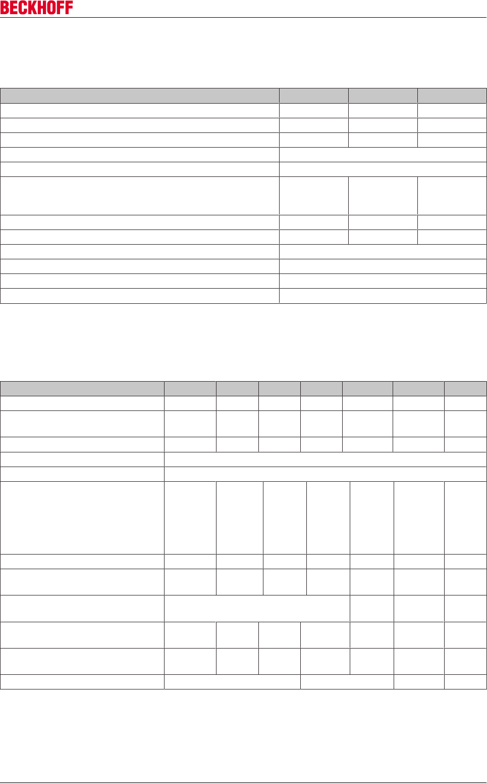
Single-phase:
AX5101 AX5103 AX5106 AX5201 AX5203 AX5206
AC-supply (max.) *) 6 A 12 A 20 A 12 A 20 A 20 A
24 V-supply (max.) 3 A
Brake resistor electronic
*) Mains fuses according to type “RK5” must be used.
Three-phase:
AX5101 AX5103 AX5106 AX5112 AX5118 AX5125
AC-supply (max.) *) 6 A 12 A 20 A 20 A 35 A 45 A
24 V-supply (max.) 3 AT
Brake resistor electronic
AX5140 AX5201 AX5203 AX5206
AC-supply (max.) *) 80 A 12 A 20 A 20 A
24 V-supply (max.) 3 AT
Brake resistor electronic
*) Mains fuses according to type “RK5” must be used.
When protected by RK5 class fuses:
AX5112:
Rated 20 A, min. 480 V
AX5118:
Rated 35 A, min. 480 V
AX5125:
Rated 45 A, min. 480 V
AX5140:
Rated 80 A, min. 480 V
Guidelines and Standards
Servo Drives AX500016 Version: 2.4
3.2.3 UL-specific notes
Use in a Pollution Degree 2 environment
Use 75 °C Copper Conductors min.
Control Board rating = 24 V
Drive intended for use over a range of motor sizes. Internal motor overload protection level is
adjustable:
The internal motor protection is parameterised via the IDN P-0-0062 “Thermal motor model”, based on the
value of the IDN S-0-0111 “Motor continuous stall current”. The IDN P-0-0062 “Time constant” is specified by
the motor manufacturer and must be entered here. The IDN P-0-0062 “Warning limit” (Default) is responsible
for deciding when a warning is to be generated. The IDN P-0-0062 “Error limit” (Default) is responsible for
deciding when the motor is to be switched off. The default values take into account the specific
characteristics of the servomotors.
Canada!
In Canada use only in combination with unit AX2090-TS50-3000, manufactured by Beck-
hoff Automation.
3.3 UL approval for devices above 60A for the US and
Canada
The German translation of this section is intended for information only!
The English version of this section is binding.
The following servo drives from the AX5000 series have a UL-Listing and must bear the CUS symbol
AX5000 with UL approval
AX5160, AX5172, AX5190, AX5191, AX5192 and AX5193.
on the name plate. If you intend to operate an AX5000 in the US or Canada, please check whether the name
plate shows the CUS label.
Below is a list of the relevant chapters that are amended with respect to the UL-Listing. Furthermore, UL-
specific remarks are listed.
3.3.1 UL-specific chapter changes
“Mains supply connection (X01)”
AX5000 shall be connected only to a grounded wye-source where the
maximum voltage does not exceed 277 V to ground.
“Connection of several servo drives to form a drive system”
Drive system with UL-Listing!
Please consult our Application Department with respect to the requirements for a drive sys-
tem with UL-Listing.
Guidelines and Standards
Servo Drives AX5000 17
Version: 2.4
3.3.2 UL-specific chapter
“External protection, UL-compliant”
Integral solid state short circuit protection does not provide branch circuit protection. Branch circuit protection
must be provided in accordance with the Manufacture Instructions, National Electrical Code and any
additional local codes.
AX5160 and AX5172:
Suitable for use on a circuit capable of delivering not more than 5000 rms symmetrical amperes, 480 V
maximum. When protected by RK5 class fuses, rated 100 A maximum.
AX5190 - AX5193:
Suitable for use on a circuit capable of delivering not more than 10000 rms symmetrical amperes, 480 V
maximum. When protected by RK5 class fuses, rated 225 A maximum.
AX5160 AX5172 AX5190 AX5191 AX5192 AX5193
AC-supply (max.) *)
24 V-supply (max.) 4 AT 10 AT
Brake resistor electronic
*) Mains fuses according to type “RK5” min. 480 V must be used.
3.3.3 UL-specific notes
Use in a Pollution Degree 2 environment
Use 75 °C Copper Conductors min.
Control Board rating = 24 V
Drive intended for use over a range of motor sizes. Internal motor overload protection level is
adjustable:
The internal motor protection is parameterised via the IDN P-0-0062 “Thermal motor model”, based on the
value of the IDN S-0-0111 “Motor continuous stall current”. The IDN P-0-0062 “Time constant” is specified by
the motor manufacturer and must be entered here. The IDN P-0-0062 “Warning limit” (Default) is responsible
for deciding when a warning is to be generated. The IDN P-0-0062 “Error limit” (Default) is responsible for
deciding when the motor is to be switched off. The default values take into account the specific
characteristics of the servomotors.
Canada!
In Canada use only in combination with unit AX2090-TS50-3000, manufactured by Beck-
hoff Automation.
3.4 Electrical isolation according to EN 50178 / VDE 0160
The power section (motor connection, DC link connection and mains connection) and the control unit are
doubly insulated against each other, so that safe protection against accidental contact is ensured at all
terminals of the control unit without additional measures. The air and creepage distances also meet the
requirements of the above standard.
Safety
Servo Drives AX500018 Version: 2.4
4 Safety
4.1 Safety instructions
Safety regulations
Please note the following safety instructions and explanations!
Product-specific safety instructions can be found on following pages or in the areas mounting, wiring,
commissioning etc.
Exclusion of liability
All the components are supplied in particular hardware and software configurations appropriate for the
application. Modifications to hardware or software configurations other than those described in the
documentation are not permitted, and nullify the liability of Beckhoff Automation GmbH & Co. KG.
Personnel qualification
This description is only intended for trained specialists in control, automation and drive engineering who are
familiar with the applicable national standards.
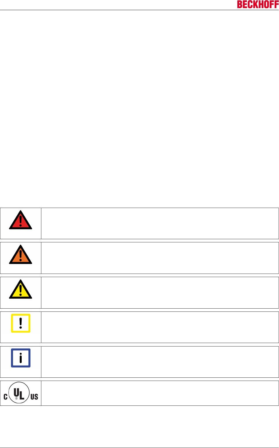
Description of symbols
In this documentation the following symbols are used with an accompanying safety instruction or note. The
safety instructions must be read carefully and followed without fail!
DANGER
Serious risk of injury!
Failure to follow the safety instructions associated with this symbol directly endangers the
life and health of persons.
WARNING
Risk of injury!
Failure to follow the safety instructions associated with this symbol endangers the life and
health of persons.
CAUTION
Personal injuries!
Failure to follow the safety instructions associated with this symbol can lead to injuries to
persons.
Attention
Damage to the environment or devices
Failure to follow the instructions associated with this symbol can lead to damage to the en-
vironment or equipment.
Note
Tip or pointer
This symbol indicates information that contributes to better understanding.
UL pointer
This symbol indicates important information about the UL-compliant.
Safety
Servo Drives AX5000 19
Version: 2.4
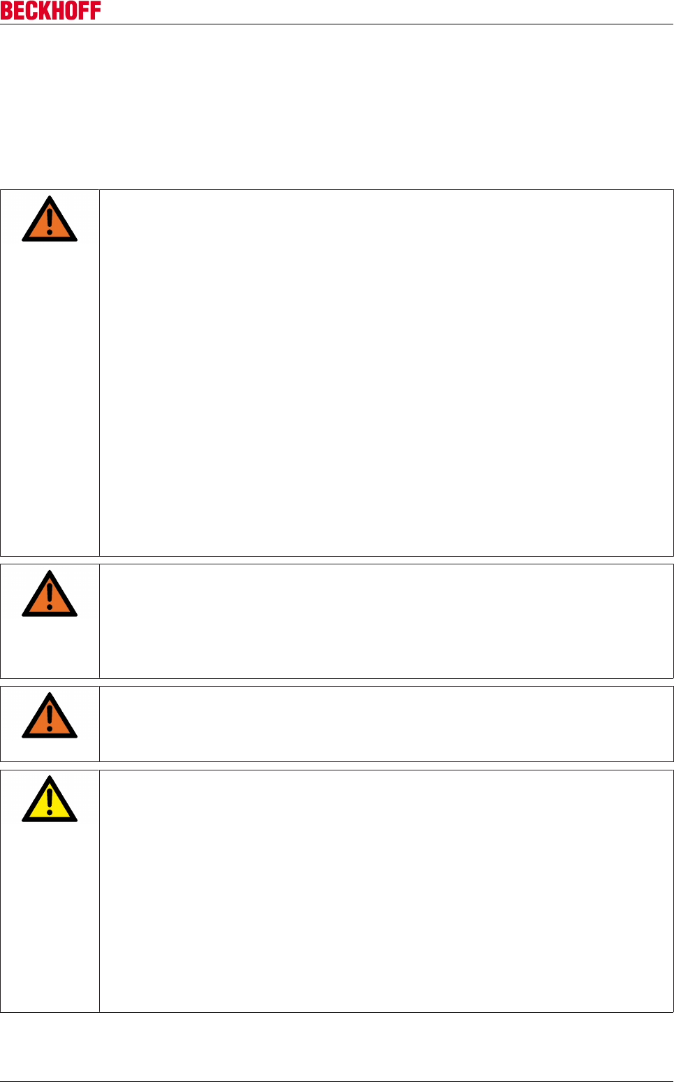
4.2 Special safety notes for servo drives
The safety instructions are designed to avert danger and must be followed during installation,
commissioning, production, troubleshooting, maintenance and trial or test assemblies.
The servo drives of the AX5000 series are not designed for stand-alone operation and must always be
installed in a machine or system. After installation the additional documentation and safety instructions
provided by the machine manufacturer must be read and followed.
WARNING
Serious risk of injury through high electrical voltage!
• Never open the servo drive when it is live. Wait until the DC link capacitors are dis-
charged. The measured voltage between the terminals "DC+ and DC-" and "RB+ and
RB-" must have dropped below 50 V. Opening the device (with the exception of expan-
sion card slots) invalidates all warranty and liability claims against Beckhoff Automation
GmbH & Co. KG.
• Negligent, improper handling of the servo drive and bypassing of the safety devices can
lead to personal injury or death through electric shock.
• Ensure that the protective conductor is connected properly.
• Disconnect the servo drive from the mains supply and secure it against reconnection
before connecting or disconnecting the pluggable terminals.
• Disconnect the servo drive from the mains supply and secure it against reconnection
before working on electrical parts with a voltage > 50 V.
• Due to the DC link capacitors, the DC link terminal points "ZK+ and ZK- (DC+ and
DC-)" and "RB+ and RB-" may be subject to dangerous voltages exceeding 875 VDC,
even after the servo drive was disconnected from the mains supply. Wait 5 minutes for
the AX5101 - AX5125 and AX520x; 15 minutes for the AX5140/AX5160/AX5172; 30
minutes for the AX5190/AX5191; 45 minutes for the AX5192/AX5193 after disconnect-
ing, and measure the voltage at the DC link terminal points "ZK+ and ZK- (DC+ and
DC-)". The device is safe once the voltage has fallen below 50 V.
WARNING
Serious risk of injury through hot surfaces!
• The surface temperature may exceed 50 °C, resulting in a risk of burns.
• Avoid touching the housing during or shortly after operation.
• Leave the servo drive to cool down for at least 15 minutes after it is switched off.
• Use a thermometer to check whether the surface has cooled down sufficiently.
WARNING
High risk of injury through uncontrolled movements!
• Read and take note of chapter "Important information for commissioning" each time be-
fore commissioning the AX5000
CAUTION
Personal injuries
• Carefully read this manual before using the servo drive thoroughly, paying particular at-
tention to the safety instructions. In the event of any uncertainties please notify your
sales office immediately and refrain from working on the servo drive.
• Only well trained, qualified electricians with sound knowledge of drive equipment may
work on the device.
• During the electrical installation it is essential to ensure that the correct fuses/protective
circuit breakers are used between the mains supply and the servo drive. Further infor-
mation can be found in the "Electrical installation" section.
• If a servo drive is installed in a machine it must not be commissioned until proof of com-
pliance of the machine with the latest version of the EC Machinery Directive has been
provided. This includes all relevant harmonized standards and regulations required for
implementation of this Directive in national legislation.

Safety
Servo Drives AX500020 Version: 2.4
Attention
Damage to the environment or devices
• During installation it is essential to ensure that the specified ventilation clearances and
climatic conditions are adhered to. Further information can be found in the "Technical
data" and "Mechanical installation" sections.
• If the servo drive is operated in contaminated ambient air, the cooling openings must be
checked regularly for blockage. These checks should be carried out several times per
day.
• The servo drives contain components at risk from electrostatic discharge caused by im-
proper handling:
ðPlease ensure you are electrostatically discharged before touching the servo drive
directly.
ðAvoid contact with highly insulating materials (synthetic fibers, plastic film etc.).
ðPlace the servo drive on a conductive surface.
ðDo not touch the motor connector while the AX5000 is in operation.

Handling
Servo Drives AX5000 21
Version: 2.4
5 Handling
5.1 Transport and storage
Transport
• Only by qualified personnel
• Only in recyclable original manufacturer's packaging
• Avoid sharp impacts
• Temperature: -40...+70°C, varying no faster than 20K / hour
• Air humidity: relative humidity max. 95%, non-condensing
• The servo drives contain components at risk from electrostatic discharge caused by improper handling.
- Please ensure you are electrostatically discharged before touching the servo drive directly.
- Avoid contact with highly insulating materials (synthetic fibers, plastic film etc.).
- Place the servo drive on a conductive surface.
• If the packaging is damaged, check the uprighter and any included accessories for visible damage.
Inform the transport company and, if necessary, the manufacturer.
Storage
• The AX5000 and its accessories must not be stored outdoors. The storage space must be adequately
ventilated and dry.
• The devices must be stored in the recyclable original manufacturer's packaging.
• The servo drives contain components at risk from electrostatic discharge caused by improper handling.
- Please ensure you are electrostatically discharged before touching the servo drive directly.
- Avoid contact with highly insulating materials (synthetic fibers, plastic film etc.).
- Place the servo drive on a conductive surface.
• Max. stack height 8 cartons
• Storage temperature: - 40...+ 55° C, varying no faster than 20 K / hour
• Air humidity: relative humidity max. 95%, non-condensing
• Storage time:
< 5 years: without limitation
Attention
Destruction of the equipment
On no account must the device be connected to 400 V if the DC link capacitors have lost
their forming.
The capacitors must be reformed (see below).
> 5 years: The dielectric (an oxidation layer with a thickness of approx. 1 µ) in the DC link capacitors
degrades over time, and the capacitors lose their forming.
Prior to commissioning of the servo drive the capacitors must be reformed. Release all electrical
connections and feed the servo drive for about 30 minutes with 230 VAC (single-phase) at terminals L1/L2 or
L2/L3.
Packaging
• Recyclable carton with inserts
• Dimensions:
(H x W x D) 348 x 324 x 175 mm
Identification: Device name plate on the outside of the carton
5.2 Maintenance
• The devices are maintenance-free

Handling
Servo Drives AX500022 Version: 2.4
• Opening the devices invalidates the warranty
5.3 Cleaning
• Soiled housing: Clean with isopropanol or similar
Do not immerse or spray!
• Contamination inside the device: Cleaning by the manufacturer
• Soiled fan guard: Clean with (dry) brush
5.4 Disposal
• Screw connections enable the servo drives to be dismantled into main components (aluminum heat
sink, steel cases, PCBs)
• The device should be disposed of by a certified disposal company. You can obtain addresses from us.
Housing components (polycarbonate, polyamide (PA6.6)) are suitable for plastic recycling.
• Metal parts can be sent for metal recycling.
• Electronic parts such as circuit boards and terminals must be disposed of in accordance with national
electronics scrap regulations.
In accordance with the WEEE 2012/96/EG Directives we take old devices and accessories back for
professional disposal, provided the transport costs are taken over by the sender.
Send the devices with the note “For disposal” to:
Beckhoff Automation GmbH & Co. KG
Huelshorstweg 20
D-33415 Verl
Product overview
Servo Drives AX5000 23
Version: 2.4
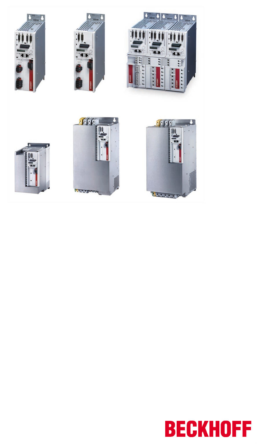
6 Product overview
6.1 Scope of supply
The AX5000 is supplied as follows:
• AX5000 in the performance class according to the order
• Connector
X01: for mains input
X02: for DC link (not for AX5140)
X03: for DC power supply (24 V)
X06: for digital inputs and outputs
X07: external brake resistor (only AX5140)
• Quick reference guide (Startup)
• Documentation on CD-ROM
Note
Connector
The D-SUB connectors X11, X12, X21, X22 (for feedback cable and resolver/Hall) and the
motor and sensor connectors X13, X14, X23, X24 are not part of the scope of delivery of
the servo drive. However, they are included with pre-assembled motor and feedback ca-
bles.
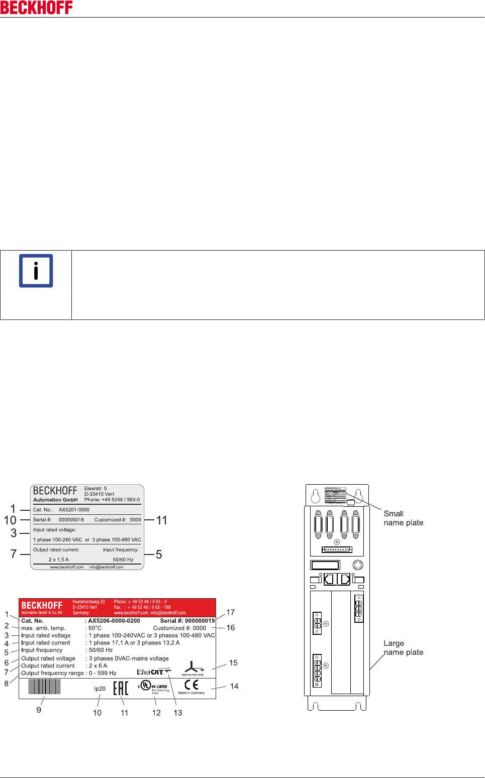
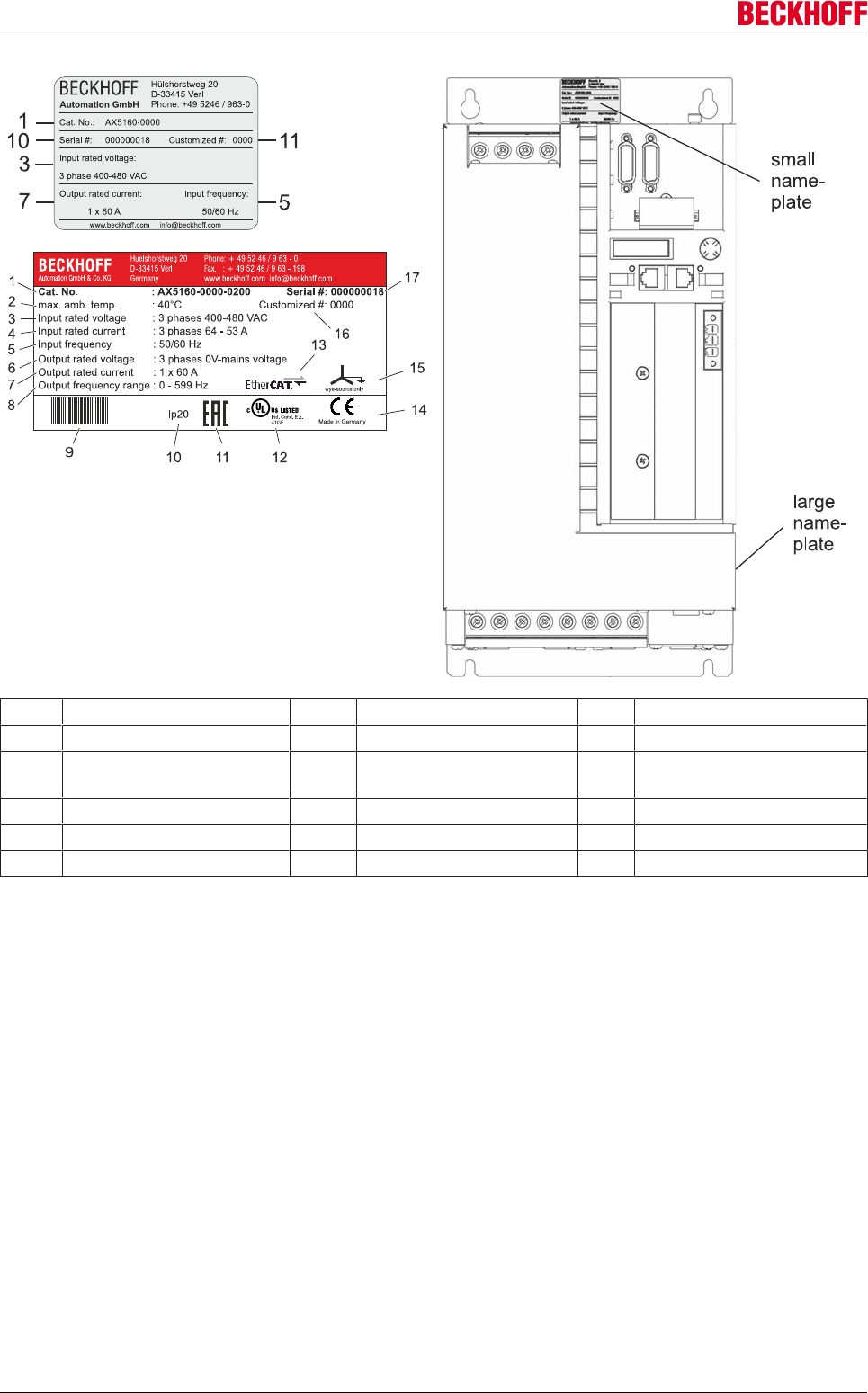
6.2 Name plate
The servo drive features two name plates.
• Large name plate: The large name plate attached at the side of the servo drive and includes
the following information:
• Small name plate: The second name plate is attached to the upper mounting flange
mounted and is designed to show the main, even if several AX5000 are
installed directly side by side. The small name plate contains the
following information.
Product overview
Servo Drives AX500024 Version: 2.4
1 Order number 7 Rated output current 13 EtherCAT compliant
2 Max. ambient temperature 8 Output frequency range 14 CE compliant
3 Rated input voltage 9 Barcode 15 Standard mains supply with
earthed center
4 Rated input current 10 Protection class 16 Customer-specific
5 Input frequency 11 EAC compliant 17 Serial number
6 Rated output voltage 12 cULus approval
Product overview
Servo Drives AX5000 25
Version: 2.4
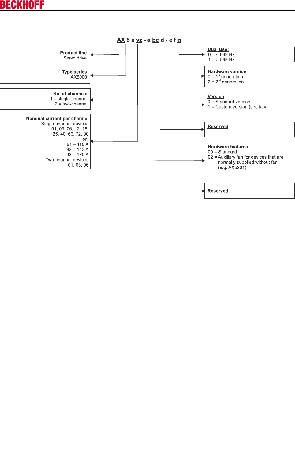
6.3 Type key
Product overview
Servo Drives AX500026 Version: 2.4
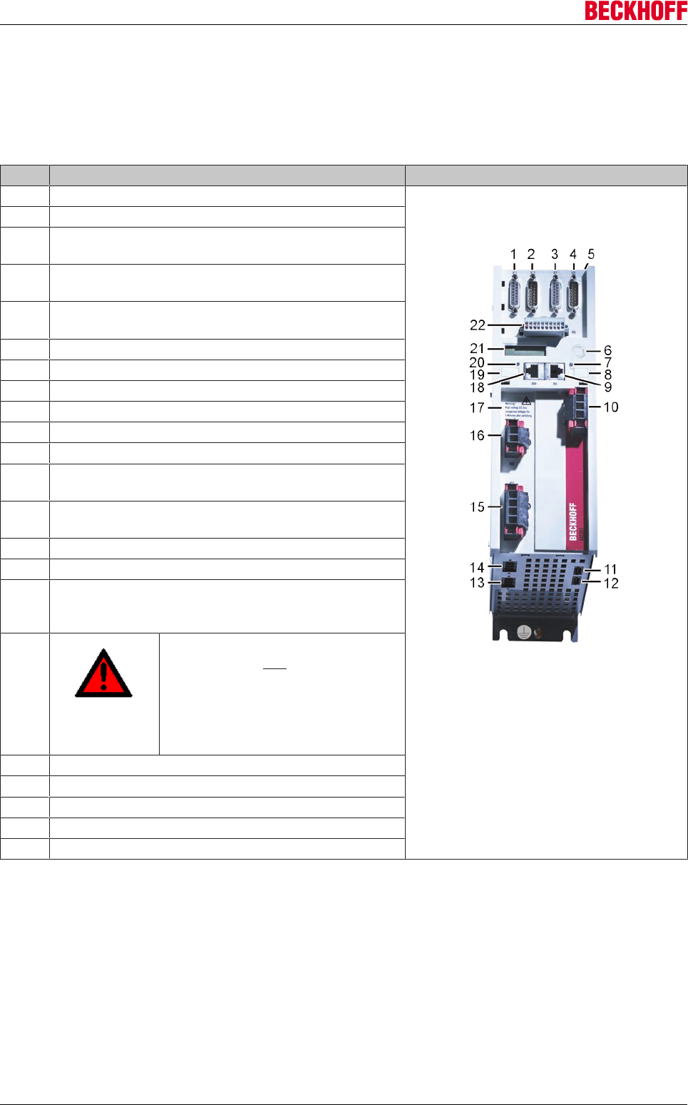
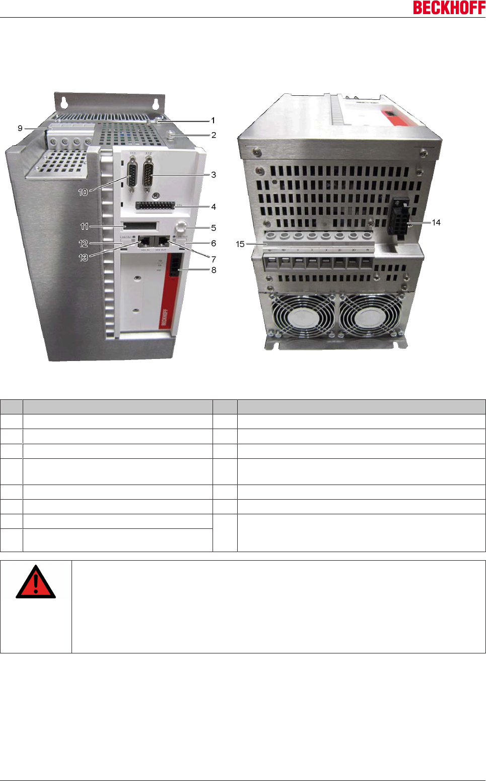
6.4 Image showing AX5101 - AX5112 and AX520x
The servo drive shown below is a two-channel device designed for a maximum current of 12 A. Components
that are only available for the second channel are identified in the item description.
Item descriptions:
No. Name
1 X11 - feedback connection, encoder
2 X12 - feedback connection, resolver
3 X21 - feedback connection, encoder
channel B (only for two-channel unit)
4 X22 - feedback connection, resolver
channel B (only for two-channel unit)
5 X3x - optional slot for safety card
X4x - optional slot for expansion cards
6 Navigation rocker
7 Status LED for EtherCAT output
8 Labelling field
9 X05 - socket for EtherCAT output
10 X03 - power supply 24 V DC input
11 X14 – sensor for motor temperature, brake and OCT
12 X24 – sensor for motor temperature, brake and OCT
channel B (only for two-channel unit)
13 X23 - motor connection (U, V, W, PE)
channel B (only for two-channel unit)
14 X13 - motor connection (U, V, W, PE)
15 X01 - mains supply 100 - 480 V
16 X02 - DC link output
(max. voltage 875 V DC)
Connection for the external brake resistor
17
DANGER
Max. voltage 875 V DC at the DC link
terminal points (X02). Once the device
has been switched off dangerous
voltage will still be present for a
further 5 minutes. The device is safe
once the voltage has fallen below 50
V.
18 X04 - socket for EtherCAT input
19 Labelling field
20 Status LED for EtherCAT input
21 Display
22 X06 - connection for digital inputs and outputs
Product overview
Servo Drives AX5000 27
Version: 2.4
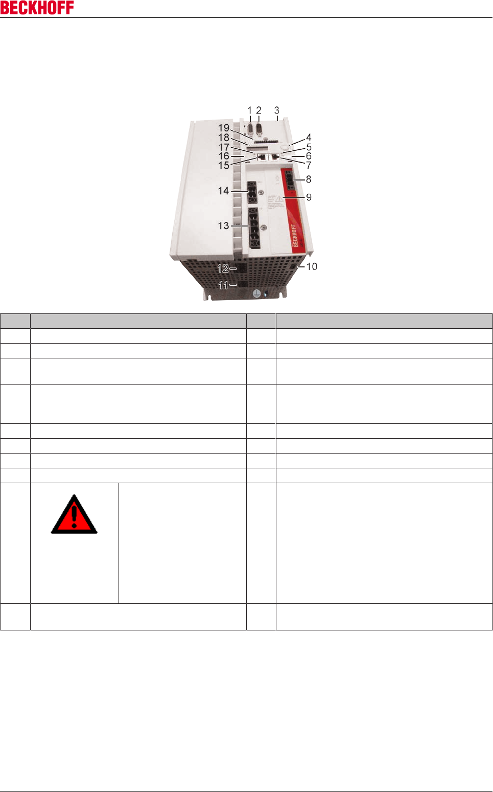
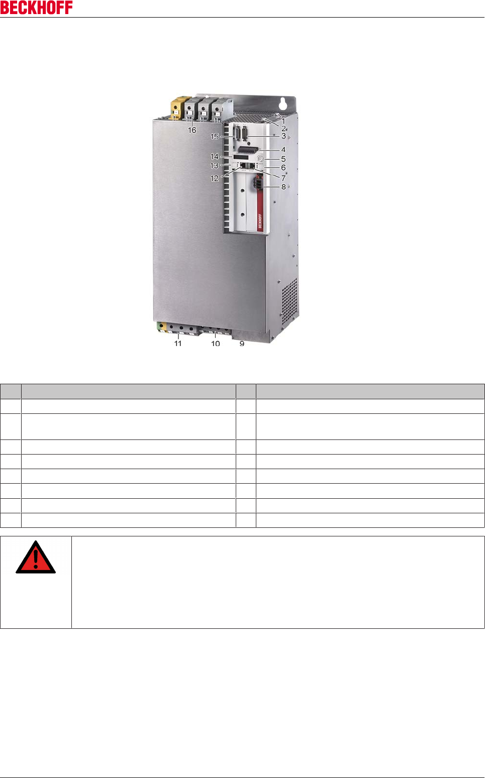
6.5 Image showing AX5118, AX5125 and AX5140
The servo drive illustrated below is an AX5140; the devices with 18 A or 25 A are structurally similar apart
from pos. 11 "X07" (external brake resistor).
Pos. Name Pos. Name
1 X11 - feedback connection, encoder 11 X07 - external brake resistor (only AX5140)
2 X12 - feedback connection, resolver 12 X13 - motor connection (U, V, W, PE)
3 X3x - optional slot for safety card
X4x - optional slot for expansion cards
13 X01 - mains supply 100 - 480 V
4 Navigation rocker 14 X02 – DC link output (max. voltage 875 V DC),
connection for external brake resistor (only
AX5118 and AX5125)
5 Status LED for EtherCAT output 15 X04 - socket for EtherCAT input
6 Labelling field 16 Labelling field
7 X05 - socket for EtherCAT output 17 Status LED for EtherCAT input
8 X03 - power supply 24 V DC input 18 Display
9
DANGER
Max. voltage 875 V DC at
the DC link terminals
(X02). Dangerous voltage
continues to be present for
around 5 minutes after the
device has been switched
off (AX5140 = 15 min.).
The device is safe once the
voltage has fallen below 50
V.
19 X06 - connection for digital inputs and outputs
10 X14 – sensor for motor temperature, brake
and OCT
Product overview
Servo Drives AX500028 Version: 2.4
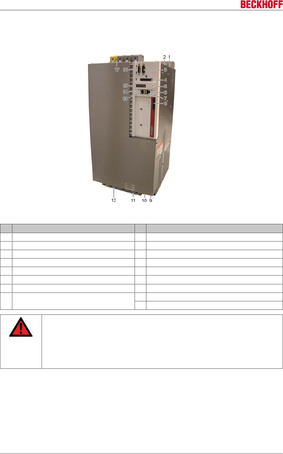
6.6 Image showing AX5160 - AX5172
The servo drive shown below is a AX5172; the AX5160 is identical.
Item descriptions:
No. Name No. Name
1 X4x - optional slot for expansion cards 9 X01 – mains supply 400 V – 480 V
2 X3x - optional slot for safety card 10 X11 - feedback connection, resolver
3 X12 - feedback connection, encoder 11 Display
4 X06 - connection for digital inputs and
outputs
12 Labelling field
5 Navigation rocker 13 X04 - socket for EtherCAT input
6 Labelling field 14 X14 - sensor for motor temperature and brake
7 X05 - socket for EtherCAT output 15 Connection for the external brake resistor DC link
output (875 V DC voltage). Motor connection (U, V, W,
PE)
8 X03 - power supply 24 V DC input
DANGER
Serious risk of injury through high electrical voltage!
Due to the DC link capacitors, the DC link terminal points "DC+ and DC-" and "RB+ and
RB-" may be subject to dangerous voltages exceeding 875 VDC, even after the servo drive
was disconnected from the mains supply.
After disconnection, wait for 15 minutes (AX5160/AX5172), 30 minutes (AX5190/AX5191)
or 45 minutes (AX5192/AX5193) and measure the voltage at the DC link-terminal points
DC+ and DC-. The device is safe once the voltage has fallen below 50 V.
Product overview
Servo Drives AX5000 29
Version: 2.4
6.7 Image showing AX5190 - AX5191
The servo drive shown below is a AX5190; the AX5191 is identical.
Item descriptions:
No. Name No. Name
1 X4x - optional slot for expansion cards 9 X14 - sensor for motor temperature and brake
2 X3x - optional slot for safety card 10 DC link output (875 V DC voltage), connection for
the external brake resistor
3 X12 - feedback connection, encoder 11 Motor connection (U, V, W, PE)
4 X06 - connection for digital inputs and outputs 12 X04 - socket for EtherCAT input
5 Navigation rocker 13 Labelling field
6 Labelling field 14 Display
7 X05 - socket for EtherCAT output 15 X11 - feedback connection, resolver
8 X03 - power supply 24 V DC input 16 X01 - mains supply
DANGER
Serious risk of injury through high electrical voltage!
Due to the DC link capacitors, the DC link terminal points "DC+ and DC-" and "RB+ and
RB-" may be subject to dangerous voltages exceeding 875 VDC, even after the servo drive
was disconnected from the mains supply.
After disconnection, wait for 15 minutes (AX5160/AX5172), 30 minutes (AX5190/AX5191)
or 45 minutes (AX5192/AX5193) and measure the voltage at the DC link-terminal points
DC+ and DC-. The device is safe once the voltage has fallen below 50 V.
Product overview
Servo Drives AX500030 Version: 2.4
6.8 Image showing AX5192 - AX5193
The servo drive shown below is a AX5192; the AX5193 is identical.
Item descriptions:
No. Name No. Name
1 X4x - optional slot for expansion cards 9 X14 - sensor for motor temperature and brake
2 X3x - optional slot for safety card 10 X07 – external brake resistor
3 X12 - feedback connection, encoder 11 DC link output (875 V DC voltage).
4 X06 - connection for digital inputs and outputs 12 Motor connection (U, V, W, PE)
5 Navigation rocker 13 X04 - socket for EtherCAT input
6 Labelling field 14 Labelling field
7 X05 - socket for EtherCAT output 15 Display
8 X03 - power supply 24 V DC input 16 X11 - feedback connection, resolver
17 X01 – mains supply 400 V – 480 V
DANGER
Serious risk of injury through high electrical voltage!
Due to the DC link capacitors, the DC link terminal points "DC+ and DC-" and "RB+ and
RB-" may be subject to dangerous voltages exceeding 875 VDC, even after the servo drive
was disconnected from the mains supply.
After disconnection, wait for 15 minutes (AX5160/AX5172), 30 minutes (AX5190/AX5191)
or 45 minutes (AX5192/AX5193) and measure the voltage at the DC link-terminal points
DC+ and DC-. The device is safe once the voltage has fallen below 50 V.
Technical description
Servo Drives AX5000 31
Version: 2.4
7 Technical description
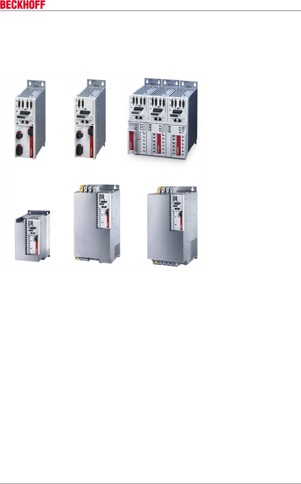
7.1 Configuration of the servo drives
The servo drives of the AX5000 series are available as single- or multi-channel versions and are optimized in
terms of function and cost-effectiveness. Integrated control technology supports fast and highly dynamic
positioning tasks. EtherCAT as a high-performance system communication enables ideal interfacing with PC-
based control technology.
The single-channel AX51xx servo drives are designed for rated motor currents up to 170 A.
The AX52xx two-channel servo drive enables operation of two motors with identical or even with different
capacity, up to a total current of 12 A. The multi-axis drives with variable motor output allocation optimize
packaging density and the cost per drive channel.
The AX5000 system enables simple and fast connection of several AX5000 devices to form a multi-axis
system through the AX-Bridge quick connection system. The pluggable supply and connection module
combines power supply, DC link, and control (24 VDC) and braking voltage.
A wide range of motor types can be connected to the AX5000. Motors of different size and type can be
connected without additional measures. Examples include synchronous, linear, torque and asynchronous
motors. The multi-feedback interface supports all common feedback standards.
such as: OCT, BiSS, EnDat, 1 Vss, Resolver.
The AX5000 was developed specifically for the EtherCAT real-time Ethernet system. The outstanding
features of EtherCAT are particularly beneficial for drive technology. They include short cycle time,
synchronicity and simultaneity. EtherCAT enables very short cycle times, even in networks containing a large
number of devices.
Technical description
Servo Drives AX500032 Version: 2.4
7.2 General technical data
UL approval
If you intend to operate an AX5000 in a region that requires UL approval, please refer to
the chapter "Guidelines and Standards".
7.2.1 Permissible ambient and operating conditions
Technical data AX5000
Ambient temperature during operation 0 °C to +50 °C (1.5 A – 40 A devices)
0 °C to +40 °C (60 A – 170 A devices), up to 55 °C with power
derating (2% / °C)
Ambient temperature during transport -25 °C to +70 °C
Ambient temperature during storage -25 °C to +70 °C (1.5 A – 40 A devices)
-25 °C to +55 °C (60 A – 170 A devices)
Air humidity 5% to 95%, non-condensing (1.5 A – 40 A units)
5% to 85 %, non-condensing (60 A – 170 A units)
Level of contamination Contamination level 2 according to EN 60204 / EN 50178
Corrosion protection Normally not required.
Under extreme operating conditions, special measures must be
agreed with the manufacturer, and implemented by the user.
Operating altitude up to 1000 m above sea level without restrictions
60 A to 170 A devices – from 1000 m up to 3000 m above sea
level with power derating (1.5% per 100 m)
Permissible installation position vertical
Ventilation Total rated device current ≤3 A: free convection,
Total rated device current >3 A: built-in temperature-controlled fan
Protection class IP20
Vibration test (EN 60068-2-6) Frequency range: 10 - 500 Hz
Amplitude: 10 - 58 Hz = 0.075mm pk-pk
59 - 500 Hz = 1 g
Shock test (EN 60068-2-27) Half sine wave amplitude: 5 g
Duration: 30ms
Number of shocks: 3 per axis and direction (total 18)
Shock test (EN 60068-2-27) Half sine wave amplitude: 5 g
Duration: 30ms
Number of shocks: 1000 per axis and direction (total 6000)
EMC Category C3 - standard
Category C1, C2 - auxiliary filter required
Approvals CE
Special operating conditions The usability of Beckhoff servo drives from the AX5000 series
under harsh operating conditions or other unfavorable conditions
must be ascertained individually in consultation between the
manufacturer and the user.
Technical description
Servo Drives AX5000 33
Version: 2.4
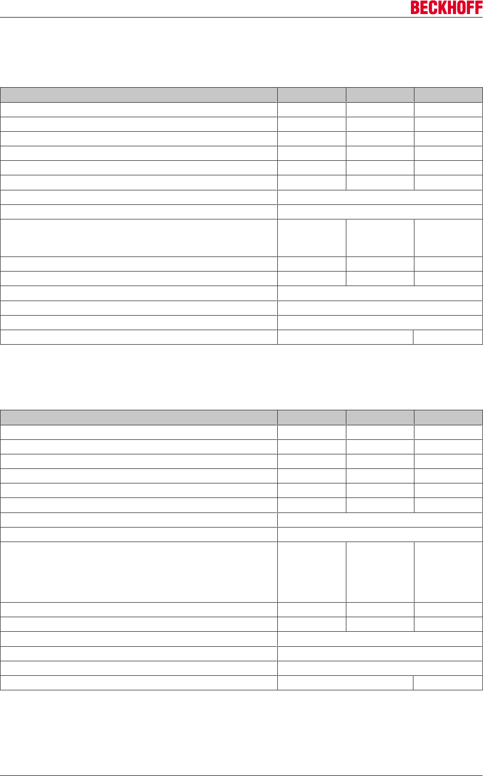
7.2.2 Electrical data - servo drive (AX5101 - AX5140)
Single-phase connection
Technical data AX5101 AX5103 AX5106
Rated output current 1.5 A 3 A 4.5 A
Minimum rated channel current at full current resolution 0.35 A 1 A 1 A
Peak output current 1) 4.5 A 7.5 A 13 A
Rated supply voltage 1 x 100-10% - 240+10% VAC
Max. DC link voltage 875 VDC
Rated apparent power S1 operation (selection)
120 V
230 V
0.3 kVA
0.6 kVA
0.6 kVA
1.2 kVA
1.2 kVA
2.4 kVA
Power loss 2) 35 W 50 W 85 W
Continuous braking power (internal brake resistor) 50 W 50 W 150 W
Max. braking power (internal brake resistor) 14 kW
Min. brake resistance (external brake resistor) 47 Ω
Max. braking power (external brake resistor) 15 kW
DC link capacity 235 µF
1) Ieff for max. 7 s, by switching frequency of 8 kHz (IDN P-0-0001)
2) S1 mode, including power supply unit, without brake chopper
Three-phase connection
Electrical data AX5101 AX5103 AX5106 AX5112 AX5118 AX5125 AX5140
Rated output current 1.5 A 3 A 6 A 12 A 18 A 25 A1) 40 A
Minimum rated channel current at
full current resolution
0.35 A 1 A 1 A 6 A 12 A 12 A 18 A
Peak output current 3) 4.5 A 7.5 A 13 A 26 A 36 A 50 A 80 A 4)
Rated supply voltage 3 x 100-10% - 480+10% VAC
2)
Max. DC link voltage 875 VDC
Rated apparent power S1 operation
(selection)
120 V
230 V
400 V
480 V
0.3 kVA
0.6 kVA
1.0 kVA
1.2 kVA
0.6 kVA
1.2 kVA
2.1 kVA
2.5 kVA
1.2 kVA
2.4 kVA
4.2 kVA
5.0 kVA
2.5 kVA
4.8 kVA
8.3 kVA
10 kVA
3.4 kVA
7.2 kVA
12.5kVA
15 kVA
4.8 kVA
10 kVA
17.3 kVA
20.8 kVA
8.3 kVA
16 kVA
28 kVA
33 kVA
Power loss 5) 35 W 50 W 85 W 160 W 255 W 340 W 510 W
Max. continuous braking power
(internal brake resistor)
50 W 50 W 150 W 90 W 200 W 200 W 150 W
Braking power (internal brake
resistor)
14 kW 26 kW 26 kW 26 kW
Min. brake resistance (external
brake resistor)
47 Ω 47 Ω 47 Ω 30 Ω 22 Ω 22 Ω 22 Ω 6)
Max. braking power (external
brake resistor)
15 kW 15 kW 15 kW 23.5 kW 32 kW 32 kW 32 kW
DC link capacity 235 µF 470 µF 1175 µF 1485 µF
1) cULus = 24 A
2) cULus = AX5118 and AX5125 = 3 x 480 VAC ± 10%
3) Ieff for max. 7 s, by switching frequency of 8 kHz (IDN P-0-0001)
4) Ieff for max. 7 s, if rotary field frequency > 3 Hz at max. 40 °C
5) S1 mode, including power supply unit, without brake chopper
6) Brake resistor < 22 Ω –> Please consult our support
Technical description
Servo Drives AX500034 Version: 2.4
7.2.3 Electrical data - servo drive (AX52xx)
Single-phase connection
Electrical data AX5201 AX5203 AX5206
Rated output current / channel 1.5 A 3 A 6 A
Minimum rated channel current at full current resolution 0.35 A 1 A 1 A
Maximum rated channel current at full current resolution 3 A 4.5 A 9 A
Total rated current with full current resolution 3 A 4.5 A 9 A
Max. peak output current 1)/channel 5 A 10 A 13 A
Peak output current 1) total device current 10 A 20 A 26 A
Rated supply voltage 1 x 100-10% - 240+10% VAC
Max. DC link voltage 875 VDC
Rated apparent power S1 operation (selection)
120 V
230 V
0.6 kVA
1.2 kVA
1.2 kVA
2.4 kVA
2.5 kVA
4.8 kVA
Power loss 2) 55 W 85 W 160 W
Max. continuous braking power (internal brake resistor) 50 W 150 W 90 W
Max. braking power (internal brake resistor) 14 kW
Min. brake resistance (external brake resistor) 47 Ω
Max. braking power (external brake resistor) 15 kW
DC link capacity 235 µF 470 µF
1) Ieff for max. 7 s, by switching frequency of 8 kHz (IDN P-0-0001)
2) S1 mode, including power supply unit, without brake chopper
Three-phase connection
Electrical data AX5201 AX5203 AX5206
Rated output current / channel 1.5 A 3 A 6 A
Minimum rated channel current at full current resolution 0.35 A 1 A 1 A
Maximum rated channel current at full current resolution 3 A 6 A 9 A
Total rated current with full current resolution 3 A 6 A 12 A
Max. peak output current (1)/channel 5 A 10 A 13 A
Peak output current (1) total device current 10 A 20 A 26 A
Rated supply voltage 3 x 100-10% - 480+10% VAC
Max. DC link voltage 875 VDC
Rated apparent power S1 operation (selection)
120 V
230 V
400 V
480 V
0.6 kVA
1.2 kVA
2.1 kVA
2.5 kVA
1.2 kVA
2.4 kVA
4.2 kVA
5.0 kVA
2.5 kVA
4.8 kVA
8.3 kVA
10.0 kVA
Power loss (2) 55 W 85 W 160 W
Max. continuous braking power (internal brake resistor) 50 W 150 W 90 W
Max. braking power (internal brake resistor) 14 kW
Min. brake resistance (external brake resistor) 47 Ω
Max. braking power (external brake resistor) 15 kW
DC link capacity 235 µF 470 µF
1) Ieff for max. 7 s, by switching frequency of 8 kHz (IDN P-0-0001)
2) S1 mode, including power supply unit, without brake chopper
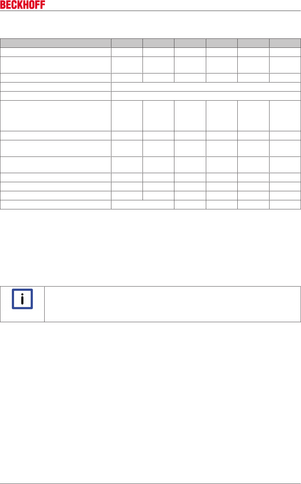
Technical description
Servo Drives AX5000 35
Version: 2.4
7.2.4 Electrical data - servo drive (AX5160 - AX5193)
Electrical data AX5160 AX5172 AX5190 AX5191 AX5192 AX5193
Rated output current1) 60 A 72 A 90 A 110 A 143 A 170 A
Minimum rated motor current at
full current resolution
25 A 40 A 50 A 60 A 70 A 80 A
Peak output current2) 1202) A 1442) A 1802) A 1802) A 2152) A 2212) A
Rated supply voltage 3x 400-10% – 480+10% VAC
Max. DC link voltage 875 VDC
Rated apparent power S1 operation
(selection)
400 V
480 V
42 kVA
45 kVA
50 kVA
54 kVA
62 kVA
67 kVA
76 kVA
82 kVA
99 kVA
107 kVA
118 kVA
127 kVA
Power loss3) 830 W 1010 W 1300 W 1600 W 2100 W 2500 W
Min. brake resistor
(external brake resistor)
13Ω 13Ω 10Ω 10Ω 6.5Ω 6.5Ω
Max. braking power
(external brake resistor)
52 kW 52 kW 67 kW 67 kW 103 kW 103 kW
Continuous braking power5) 37 kW 52 kW 56 kW 65 kW 65 kW 65 kW
Mains chokes4) AX2090-ND50 --- --- 0090 0110 0143 0170
Mains filters4) AX2090-NF50 integrated integrated 0100 0150 0150 0180
DC link capacity 900 µF 1060 µF 2120 µF 3180 µF 4240 µF
1)With a rated supply voltage of 480 V, the rated current must be reduced by 10%.
The specified values apply for an initial rotational frequency > 3 Hz
2)Ieff for max. 3 s with a preload of max. 70% of the rated output current, a mains voltage of 400 VAC and a
switching frequency by 8 kHz (P-0-0001).
3)S1 mode, including power supply unit, without brake chopper
4)Required for compliance with EN 61800-3 (EMC product standard) C3 (industrial environment) with max. 25
m motor cable length.
5) Based on a mains voltage of 3 x 400 Veff and a frequency of 8 kHz.
Note
Derating and switching frequency of the servo drive!
For further information of the Derating and the switching frequency from the servo drive
AX5000, please look at the english version of the IDN-Description (P-0-0001 Switching fre-
quency of the IGBT module).
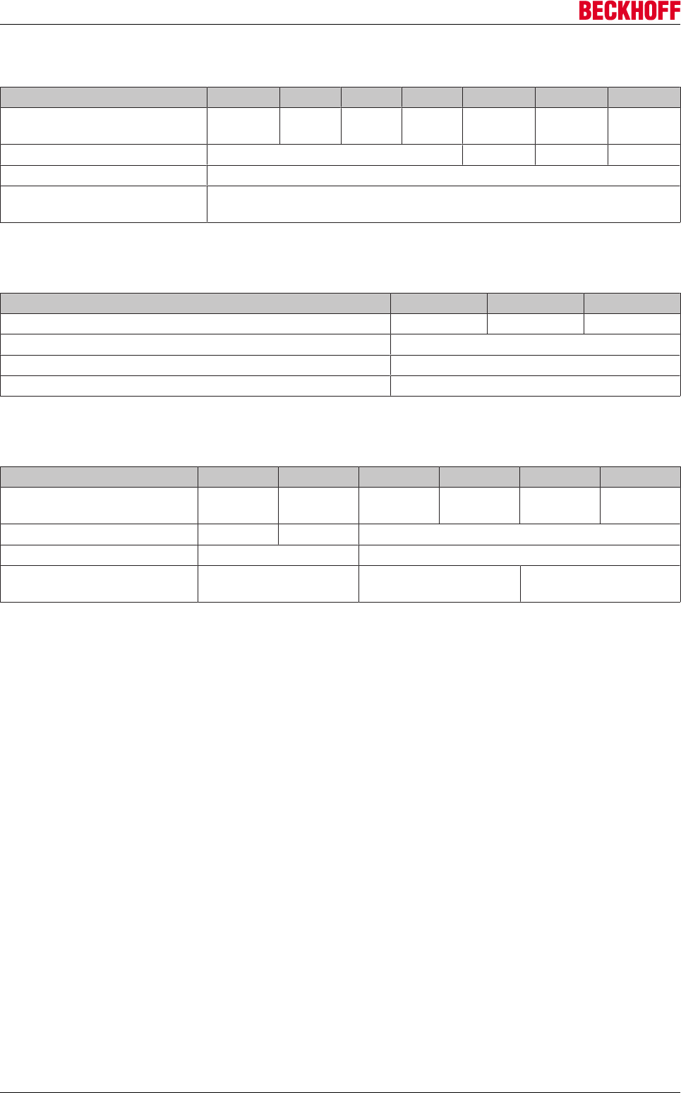
Technical description
Servo Drives AX500036 Version: 2.4
7.2.5 Mechanical data - servo drive (AX5101-AX5140)
Mechanical data AX5101 AX5103 AX5106 AX5112 AX5118 AX5125 AX5140
Weight approx. 4
kg
approx.
4 kg
approx.
5 kg
approx.
5 kg
approx. 11
kg
approx. 11
kg
approx. 13
kg
Width 92 mm 185 mm 185 mm 185 mm
Height without plugs 274 mm
Depth without connectors /
accessories
232 mm
7.2.6 Mechanical data - servo drive (AX52xx)
Mechanical data AX5201 AX5203 AX5206
Weight approx. 5 kg approx. 6 kg approx. 6 kg
Width 92 mm
Height without plugs 274 mm
Depth without connectors / accessories 232 mm
7.2.7 Mechanical data - servo drive (AX5160 - AX5193)
Mechanical data AX5160 AX5172 AX5190 AX5191 AX5192 AX5193
Weight approx. 14
kg
approx. 14
kg
approx. 31
kg
approx. 31
kg
approx. 38
kg
approx. 38
kg
Width 190 mm 283 mm 283 mm
Height without plugs 345 mm 540 mm
Depth without connectors /
accessories
259 mm 253 mm 334 mm
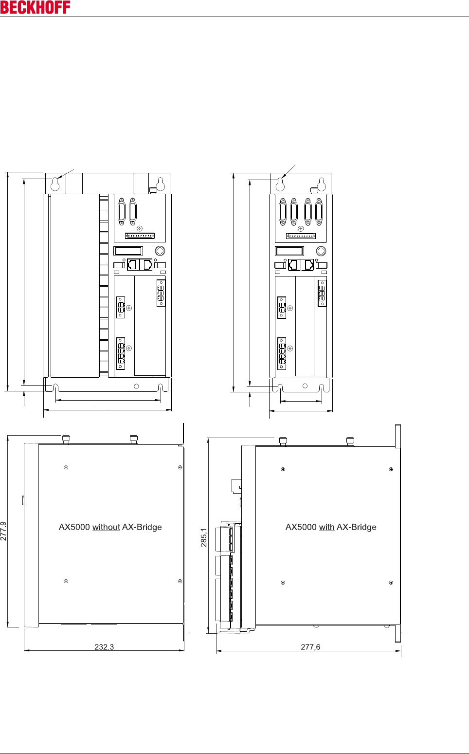
Technical description
Servo Drives AX5000 37
Version: 2.4
7.3 Dimensions
7.3.1 AX5000 as single device (1.5 A - 40 A)
All dimensions in millimeters.
6.5
299
153
8,2
185
317.2
AX5118 / AX5125 / AX5140 AX5101-AX5112 / AX5201-AX5206
299.2
60
8
92
317.2
6.5
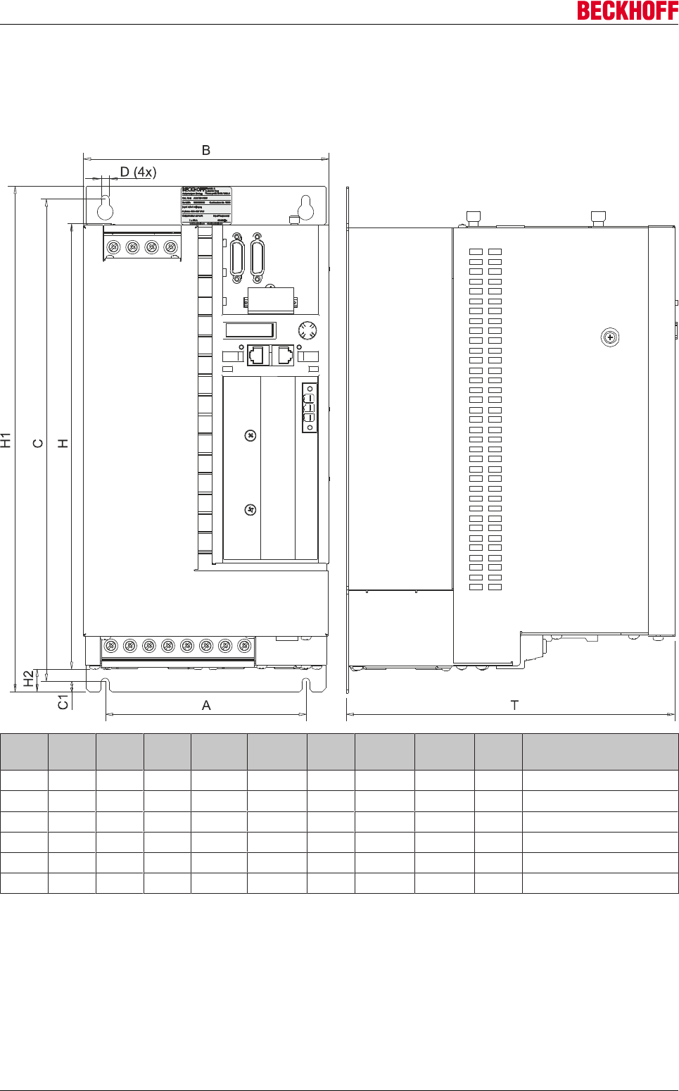
Technical description
Servo Drives AX500038 Version: 2.4
7.3.2 AX5000 as single device (60 A - 170 A)
The specified measurements relate to the actual device, without connectors and cables.
AX5160, AX5172, AX5190, AX5191, AX5192, AX5193
AX A
[mm]
B
[mm]
C
[mm]
C1
[mm]
D [mm] H
[mm]
H1
[mm]
H2
[mm]
T
[mm]
Fastening screws
5160 158 190 380 8 6.5 345 398 16.5 259 4 x M5
5172 158 190 380 8 6.5 345 398 16.5 259 4 x M5
5190 200 280 582 10 9 540 603 10 254 4 x M8
5191 200 280 582 10 9 540 603 10 254 4 x M8
5192 200 280 575 10 9 540 600 20 335 4 x M8
5193 200 280 575 10 9 540 600 20 335 4 x M8

Technical description
Servo Drives AX5000 39
Version: 2.4
7.4 Properties
• High-speed EtherCAT system communication
• Wide voltage range: 1 x 100-10% VAC - 1 x 240+10% VAC … 3 x 100-10%VAC - 3 x 480+10% VAC
• Multi-feedback interface
• flexible motor type selection
• scalable wide range motor current measurement
• High-speed capture inputs
• Diagnostic and parameter display
• integrated mains filter
• Optional safety functions: restart lock, intelligent TwinSAFE safety functions
• compact design for simple control cabinet installation
• AX-Bridge - the quick connection system for power supply, DC link and control voltage
The integrated, fast AX5000 control technology with a current control cycle of up to 62.5µs supports fast and
highly dynamic positioning tasks. The drives are designed as single- or two-channel servo drives:
•AX51xx: single-channel servo drive
rated motor current: 1 A, 3 A, 6 A, 12 A, 18 A, 25 A, 40 A, 60 A, 72 A, 90 A, 110 A, 143 A, 170 A
•AX52xx: two-channel servo drive
rated motor current: 2 x 1 A, 2 x 3 A, 2 x 6 A (with flexible allocation of total device current on both
axes)
The 2-channel servo drives with variable motor output allocation enable operation of two motors with
identical or even with different capacity on a single servo drive. For example, an asynchronous motor with a
rated current of 1 A and a linear motor with a rated current of 9 A can be operated with a servo drive with two
6 A channels. The total current is relevant for the device utilization.
The AX Bridge (only up to AX5140) enables convenient and fast connection of several servo drives of the
AX5000 series to form a drive system. This pluggable supply and connection module combines power
supply, DC link and control voltage (24 VDC) and enables fast installation and commissioning.
The AX5000 offers flexible and universal connection options. It supports
• almost all feedback systems, including robust resolvers via OCT, sine/cosine encoders with EnDat,
Hiperface or BiSS.
• a wide range of motor types such as asynchronous, synchronous, torque or linear motors.
7.5 Wide voltage range
In order to facilitate worldwide application with different voltage systems, the AX5000 features a wide voltage
range. Virtually any voltage system can be connected with one and the same device, from 1 x 100 VAC - 1 x
240 VAC to 3 x 100 VAC - 3 x 480 VAC. This reduces stock-keeping and prevents destruction through
unsuitable mains voltage. Examples for different mains systems:
• 1 x 100 VAC, 3 x 200 VAC for Asia
• 1 x 115 VAC, 3 x 230 VAC, 3 x 480 VAC for North America
• 1 x 220 VAC, 3 x 380 VAC for China
• 1 x 230 VAC, 3 x 400 VAC for Europe

Technical description
Servo Drives AX500040 Version: 2.4
7.6 Variable motor interface
The AX5000 supports the connection of different motor types, ranging from standard asynchronous motors
to ironless linear motors:
Motor type Operation mode and limits
Brushless synchronous motors • Servo mode with feedback
Torque motors • Multipole servomotors with high torque and
relatively low speed
Linear motors (iron core) • Servo mode with feedback
Linear motors (ironless) • Servo mode with feedback
Asynchronous motor • Frequency converter mode without feedback
• High-frequency spindle up to 60,000 rpm
(only for devices of the AX5xxx-0000-x21x
series "Dual Use [}12]")
• Servo mode with feedback
7.7 Multi-feedback interface
AX5000 offers interfaces for all common feedback systems. No additional interface cards are required.
Connection options:
• OCT One cable feedback system
• Sine / cosine 1 Vpp
• EnDAT, single- and multi-turn
• Hiperface, single- and multi-turn
• BiSS, single- and multi-turn
• Resolver, 2-pin - 8-pin
• Support for electronic motor name plates
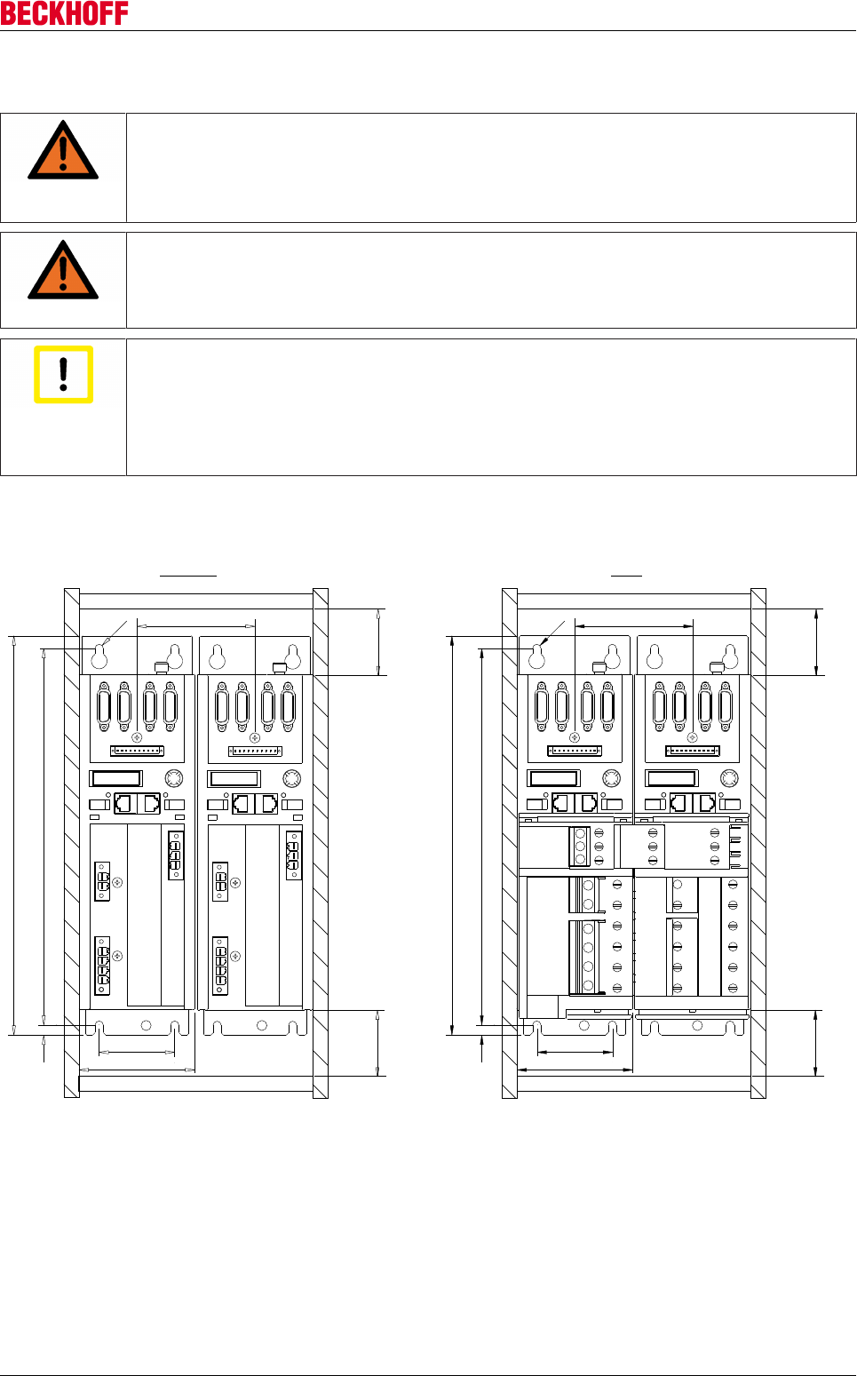
Mechanical installation
Servo Drives AX5000 41
Version: 2.4
8 Mechanical installation
WARNING
Caution - Risk of injury!
• The servo drives may only be installed by trained, qualified personnel. The qualified
personnel must know and comply with the national accident prevention regulations.
• Safety boots must be worn.
WARNING
Caution - Risk of injury through electric shock!
De-energize all electrical components (servo drive, control cabinet, etc.) before commenc-
ing the installation or deinstallation.
Attention
Destruction of the servo drive!
• Always install the servo drive vertically.
• Provide adequate ventilation for the servo drive. The permissible ambient conditions
are specified in the chapter "Technical data".
• It is essential to adhere to the required distances (see diagrams below).
8.1 Installation examples (1.5 A - 40 A devices)
299.2
60
93
8
Min. 100
Min.100
92
317.2
6.5
299.2
60
93
8
Min. 100
Min.100
92
317.2
6.5
Cable duct Cable duct
Cable duct Cable duct
AX5000 AX-Bridgewithout AX5000 AX-Bridgewith
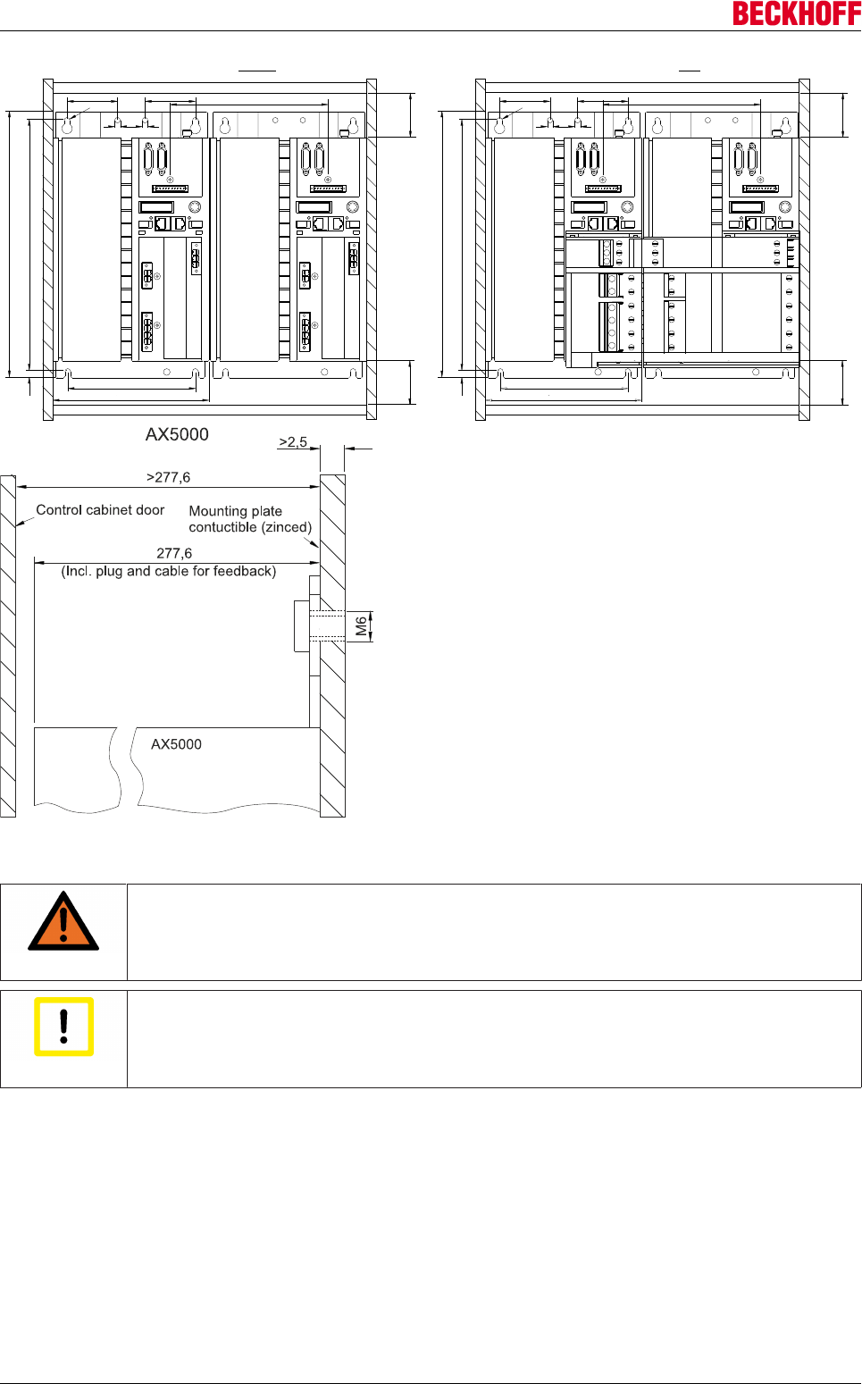
Mechanical installation
Servo Drives AX500042 Version: 2.4
Min.200 (AX5140)
Min.200 (AX5140)
6.5
6,56,5
60 60
6.5
6,56,5
60 60
299
299
153 153
186 186
8,2
8,2
Min. 100
Min. 100
Min.100
Min.100
185 185
317.2
317.2
Cable duct Cable duct
Cable duct Cable duct
AX5118 / AX5125 / AX5140 AX-Bridgewithout AX5118 / AX5125 / AX5140 AX-Bridgewith
WARNING
Caution - Risk of injury through electric shock!
The mounting plate must be earthed according to the statutory regulations.
Attention
Earthing!
Non-compliant earthing of the AX5000 can cause EMC problems.
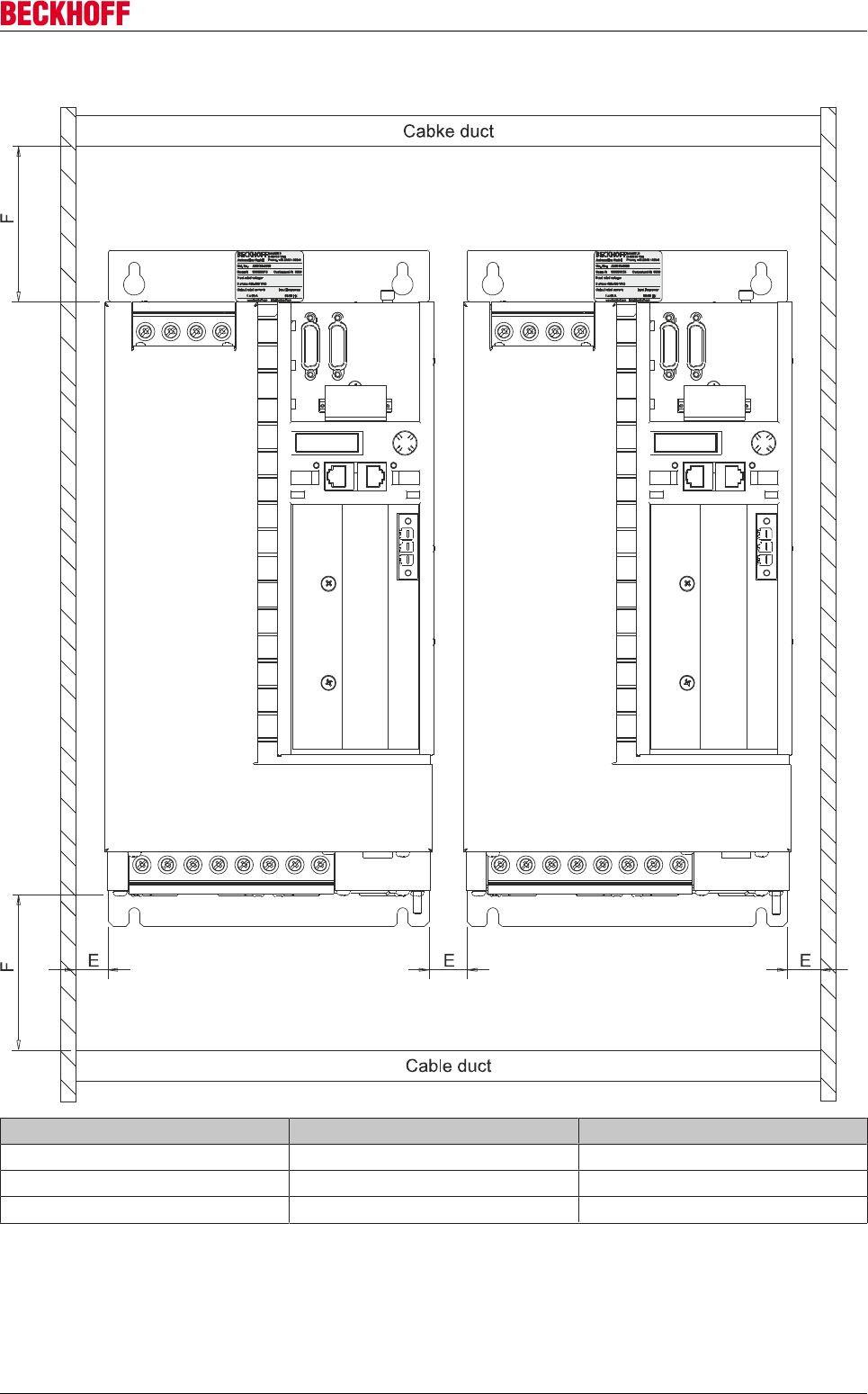
Mechanical installation
Servo Drives AX5000 43
Version: 2.4
8.2 Installation examples (60 A - 170 A devices)
AX F [mm] E [mm]
5160 and 5172 ≥ 180 20
5190 and 5191 ≥ 180 40
5192 and 5193 ≥ 180 40
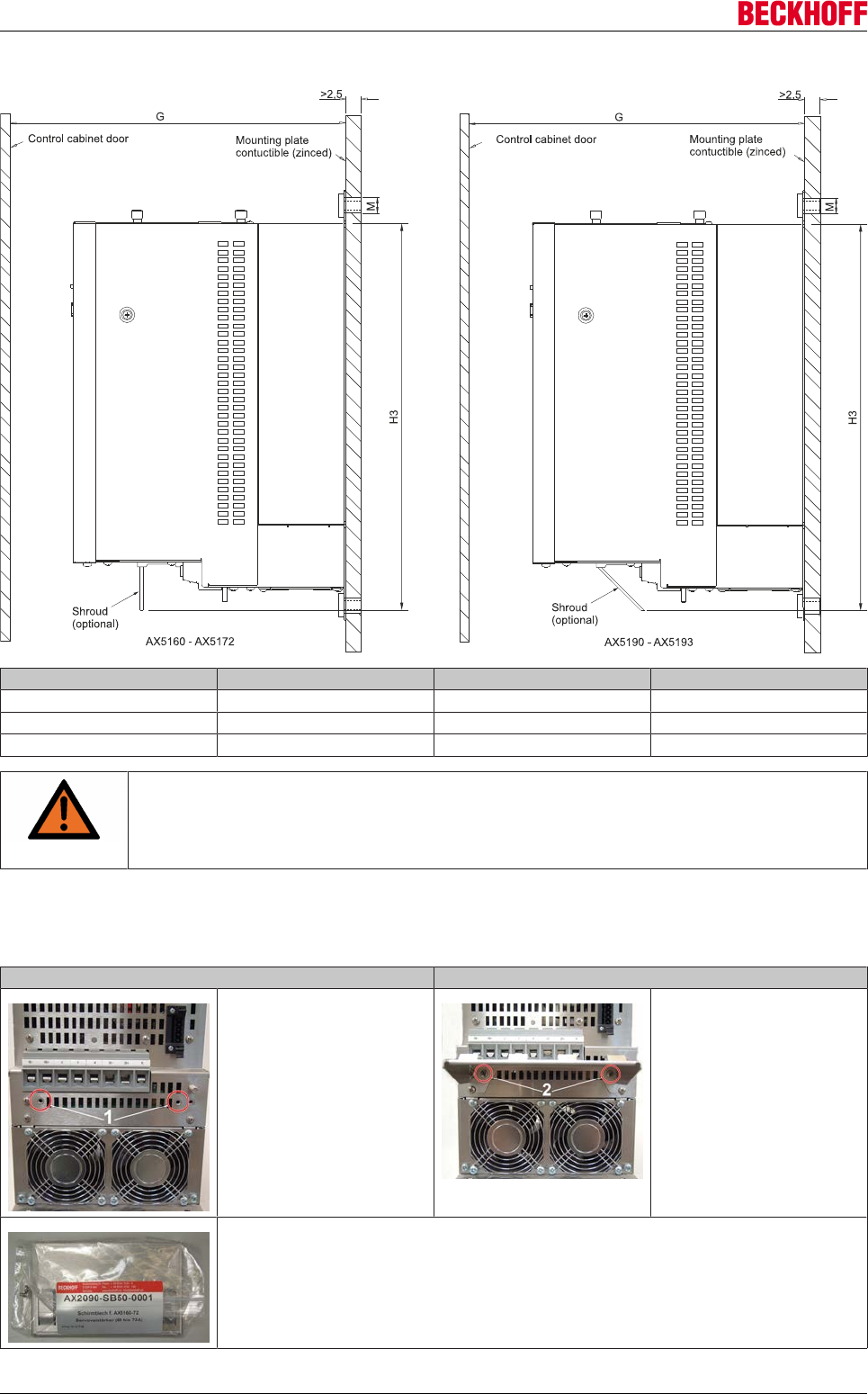
Mechanical installation
Servo Drives AX500044 Version: 2.4
Installation in the control cabinet
AX G [mm] M [mm] H3 [mm]
5160 and 5172 ≥ 300 4 x M5 445
5190 and 5191 ≥ 300 4 x M8 640
5192 and 5193 ≥ 500 4 x M8 640
WARNING
Caution - Risk of injury through electric shock!
The mounting plate must be earthed according to the statutory regulations. Non-compliant
earthing of the AX5000 can cause EMC problems.
Installation of the shield (optional)
AX5160 and AX5172
Preparing for installation Shroud mounting
1.) The threaded holes (1) for
mounting of the shroud, are in
the delivery state of the servo
drive AX5160 / AX5172, not fit-
ted with screws.
Check before mounting the
shroud, if the threaded holes are
free of Dirt.
2.) Position the shroud.
3.) Mounted the shroud with the
screws (2). Use for mounting
only the screws of the shroud
set. The screws are included in
the shroud set.
4.) Connect the wires to the ter-
minals provided. Attach the
shield by the tabs.
Shroud set for AX5160 and AX5172 consisting of shroud and mounting screws (2 x M4 x 10).
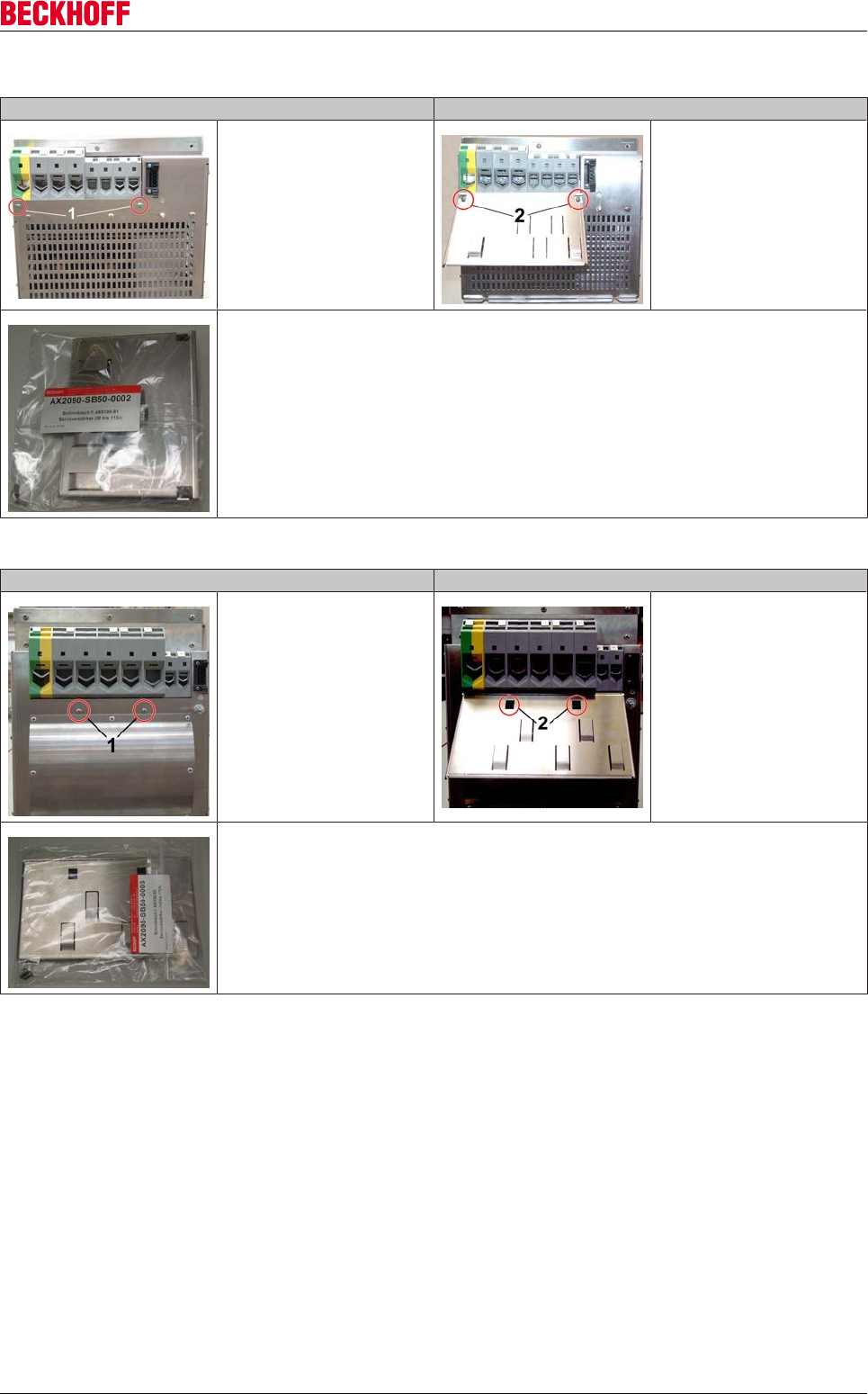
Mechanical installation
Servo Drives AX5000 45
Version: 2.4
AX5190 and AX5191
Preparing for installation Shroud mounting
1.) Remove the 2 pre-mounted
screws.
2.) Position the shroud.
3.) Mounted the shroud with the
screws (2). Use for mounting
only the screws of the shroud
set. The screws are included in
the shroud set.
4.) Connect the wires to the ter-
minals provided. Attach the
shield by the tabs.
Shroud set for AX5190 and AX5191 consisting of shroud and mounting screws (2 x M4 x 10).
AX5192 and AX5193
Preparing for installation Shroud mounting
1.) Remove the 2 pre-mounted
screws.
2.) Position the shroud.
3.) Mounted the shroud with the
screws (2). Use for mounting
only the screws of the shroud
set. The screws are included in
the shroud set.
4.) Connect the wires to the ter-
minals provided. Attach the
shield by the tabs.
Shroud set for AX5192 and AX5193 consisting of shroud and mounting screws (2 x M4 x 10).
Electrical installation
Servo Drives AX500046 Version: 2.4
9 Electrical installation
UL approval
If you intend to operate an AX5000 in a region that requires UL approval, please refer to
the chapter "Guidelines and Standards".
WARNING
Caution - Risk of injury!
• The servo drives may only be installed by trained, qualified personnel. The qualified
personnel must know and comply with the national accident prevention regulations.
• Safety boots must be worn.
WARNING
Caution – Risk of injury through electric shock!
De-energize all electrical components (servo drive, control cabinet, etc.) before commenc-
ing the installation or deinstallation.
DANGER
Serious risk of injury through electric shock!
Due to the DC link capacitors dangerous voltage may persist at the DC link contacts "X02"
after the servo drive has been disconnected from the mains supply. Wait 5 minutes after
disconnection and measure the voltage on the DC link contacts DC+ and DC-. The device
is safe once the voltage has fallen below 50 V.
WARNING
Caution – Risk of injury through electric shock!
• Before installation, wiring and commissioning it is essential to read the section on
"Safety".
• Before installing, uninstalling or connecting the servo drive and the motors please note
the following: - Remove all relevant mains fuses. - Switch off the main system switch
and secure it with a lock. - Put up a warning sign.
• The control and power connections for the motors may be live, even if the motor is pre-
vented from rotating by the internal brake.
CAUTION
Destruction of the AX5000!
• Check the rated voltage and current of the servo drive and the connected motors.
• Once the AX5000 has been disconnected from the mains supply, (emergency off,
mains contactor etc.), wait at least 3 minutes before switching it on again or query the
status of IDN "P-0-0205" (see "IDN description" in the documentation).

Electrical installation
Servo Drives AX5000 47
Version: 2.4
9.1 Connection of several servo drives to form a drive
system
Attention
Destruction of the equipment!
• The connection sequence of the devices is not arbitrary. The total rated current of the
device must decrease from the power supply. AX5112-AX5106-AX5203-AX5201 = OK
AX5201-AX5112-AX5203 ≠ OK
• All devices in a drive system are always to be disconnected from and reconnected to
the mains supply together (emergency stop, mains contactor etc.).
CAUTION
Danger for persons and equipment
Note the total rated current of the connected devices. According to CE, the current carrying
capacity of the power busbars of the AX Bridge is limited to 85 A.
Attention
Destruction of the external brake resistor!
An external brake resistor may not be connected to the X02 terminal point (DC link) in a
drive system. Use an external brake module AX5021 for this.
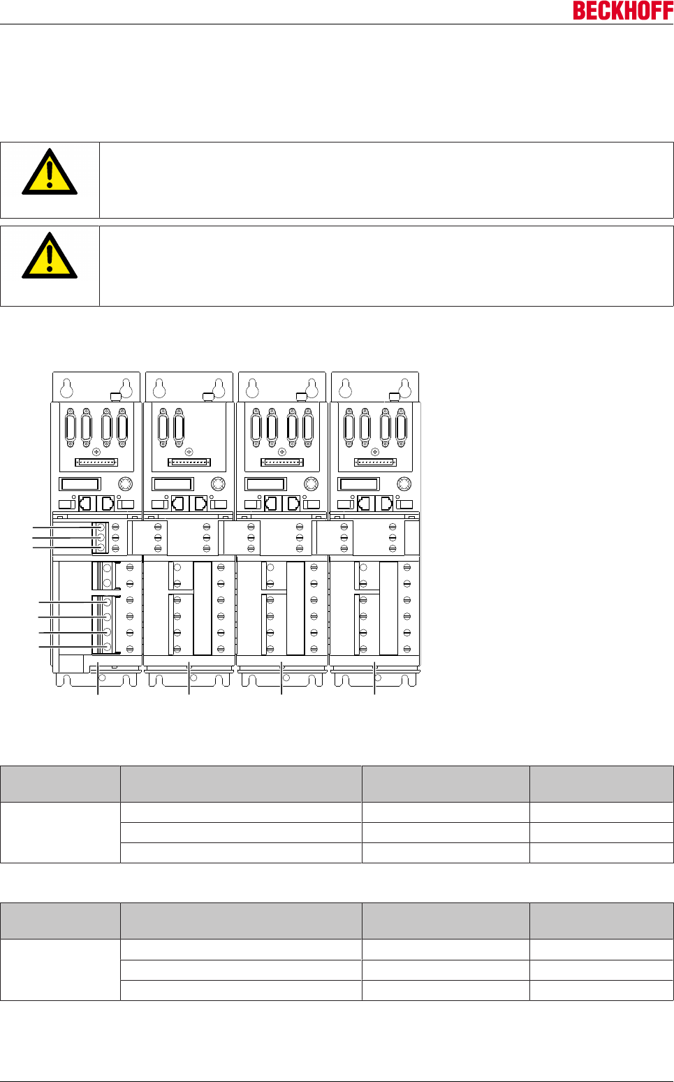
Electrical installation
Servo Drives AX500048 Version: 2.4
9.1.1 Connection example - module AX5901 and AX5911 (AX Bridge)
This connection option enables a safe system to be set up very quickly. The modules are attached to plug
contacts X01, X02 and X03, the relevant slides are pushed to the left and screwed tight. According to CE,
the current carrying capacity of the power busbars of the AX Bridge is limited to 85 A.
CAUTION
Risk of injury due to electric shock!
Move all busbar sliders to the left limit stop in order to ensure full current carrying capacity.
Then tighten all screws with a torque of 2.2 Nm.
CAUTION
Personal injuries!
Please ensure that the connection line for the AX5901 supply module is adequately dimen-
sioned. The dimensioning depends on the total rated current and must comply with
EN60204-1. A 3-phase connection must be used if the total rated current exceeds 9 A.
PE
L3/N
AX52xx AX51xx AX52xx AX52xx
GND
L2
Us
L1
UP
AX5901 AX5911 AX5911 AX5911
AX5901 (AX520x and AX5101 - AX5125)
Terminal points Conductor design Max. conductor cross-
section
Tightening torque
L1-L3, PE solid wire 10 mm2, AWG 7 2.2 Nm
stranded wire with ferrule 16 mm2, AWG 5 2.2 Nm
stranded- / multi-wire 25 mm2, AWG 3 2.2 Nm
AX5902 (AX5140)
Terminal points Conductor design Max. conductor cross-
section
Tightening torque
L1-L3, PE solid wire 16 mm2, AWG 5 3.2 ± 0.8 Nm
stranded wire with ferrule 16 mm2, AWG 5 3.2 ± 0.8 Nm
stranded- / multi-wire 25 mm2, AWG 3 3.2 ± 0.8 Nm
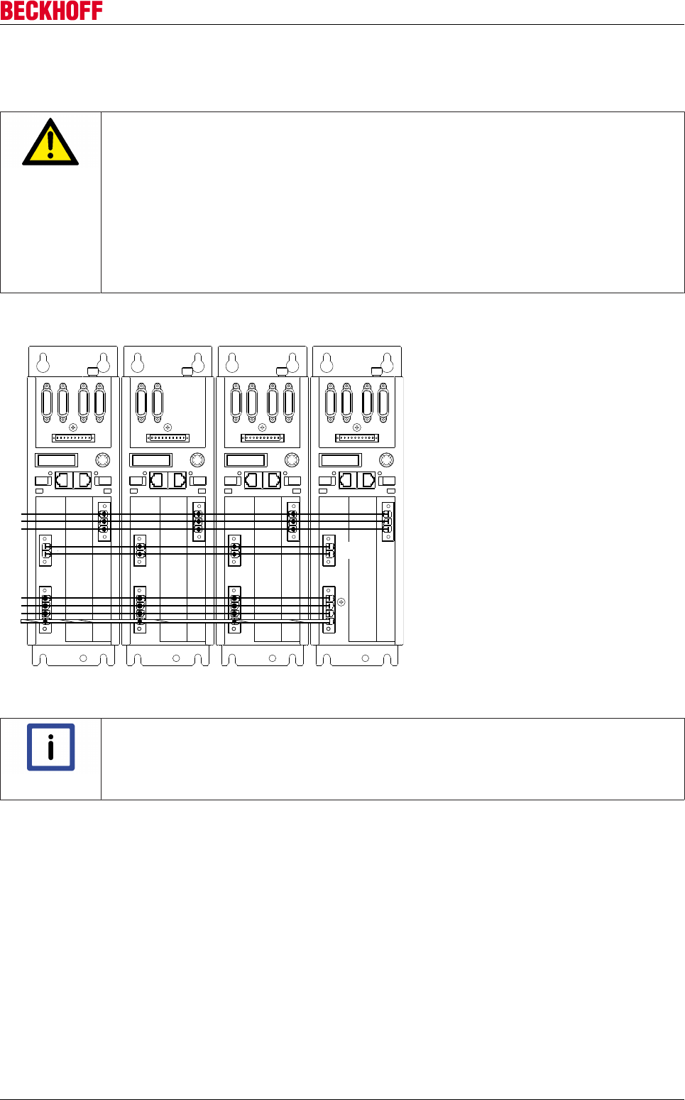
Electrical installation
Servo Drives AX5000 49
Version: 2.4
9.1.2 Connection example - wiring in series without AX bridge
Wire the relevant connections using individual cables.
CAUTION
Damage to persons and devices!
• Please ensure that the final supply network connection cable is adequately dimen-
sioned. The dimensioning depends on the total current and must comply with
EN60204-1.
• To establish a DC link system wire the X02 connections with a suitable cable. Voltages
up to 890 V may be present.
• The connectors are designed for a maximum current of 41 A and a maximum conductor
cross-section of 6 mm².
• Avoid phase reversal between the devices!
PE
GND
L3/N
US
UP
L2
L1
AX52xx AX51xx
DC -
DC+
AX52xx AX52xx
Note
No UL drive system!
The following figure shows an AX wiring in series configuration without AX Bridge. To con-
figure a UL drive system, please refer to the information in chapter 9.1.3 "UL drive system –
configuration example".
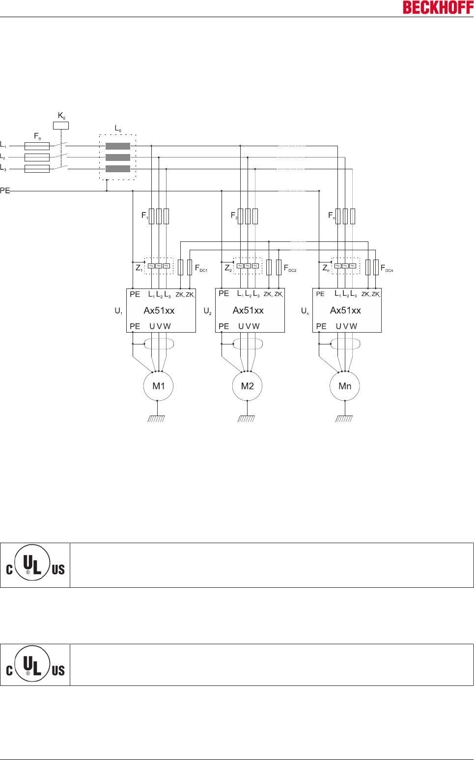
Electrical installation
Servo Drives AX500050 Version: 2.4
9.1.3 Connection example – DC link group (60 A to 170 A devices)
This connection technique enables you to establish a DC link group for servo drives from the series AX5160
to AX5193
The following illustration shows a possible configuration example.
Key to picture:
F0-n = Mains fuses = UL fuse (480 VAC)
FDC1-DCn = DC link fuses (DC fuses) = UL fuse (700 VAC / 800 VDC)
e.g. ferrule FWP from Cooper-Bussmann
K0= Common mains contactor
L0= Mains choke
Z1-n = Mains filter (optional)
Drive system with UL approval!
Before implementation a DC link group, please contact your UL approval body and discuss
further necessary boundary conditions.
Dimensioning of the UL fuses FDC1-FDCn
The dimensioning of the fusesFDC1 to FDCn in the DC link is application-dependent. The motor and the load
profile are incorporated directly into the calculation. Please consider this when dimensioning.
Fuse holders with UL approval
Note when using UL fuses that the necessary fuse holders also have to carry UL approval.

Electrical installation
Servo Drives AX5000 51
Version: 2.4
Mains choke
To ensure balancing of all servo drives, a common mains choke (Lo) must be provided. The rated current of
the mains choke must be ≥ the rated current of the common mains fuse (F0) of the drive system (see section
"Mains fuse"). The short-circuit voltage Uk of the mains choke must be 2%
Dimensioning the mains fuse
The following section describes the dimensioning of the mains fuse to be used for individual devices and the
use of mains fuses in the DC link group.
Series AX5160 to AX5193 (60 A to 170 A):
Individual device:
• The main fuse must be dimensioned such that it corresponds to the rated current of the servo drive
multiplied by the correction factor 1.1. The value determined is rounded up to the next larger standard
step (see section Electrical Data [}35]). If the size of the current (in your application) on the mains side
is known, the mains fuse can also be dimensioned smaller in accordance.
• The cross-section of the mains supply cable must be dimensioned such that the permissible current
load of the cable is ≥ the rated current of the selected mains fuse (see section Motors and Cables
[}105]).
DC link group:
• The common main fuse (F0) must be dimensioned such that it corresponds to the sum of all the rated
currents of the servo drives multiplied by the correction factor 1.1. The value determined is rounded up
to the next larger standard step (see section dimensioning example). If the size of the current (in your
application) on the mains side is known, the mains fuse (F0) can also be dimensioned smaller in
accordance.
• The cross-section of the mains supply cable must be dimensioned such that the permissible current
load of the cable is ≥ the rated current of the selected mains fuse.
• The cross-section of the mains supply cable and the mains fuses (F1 to Fn) of the individual servo
drives in the DC link group are to be selected analogously to the operation of the individual servo
drives (see section "Individual devices").
The local regulations and the local conditions (ambient temperature, cable routing, etc.) must be referred to
when determining the permissible current load of the cables (selection of the necessary cross-section – see
section Motors and Cables [}105]).
Dimensioning example:
1 x AX5172 + 2 x AX5192 + 1 x AX5193
72 A + 286 A + 170 A = 528 A x 1.1 = 581 A 630 A selected
Electrical installation
Servo Drives AX500052 Version: 2.4
Mains switch-on conditions:
The mains must be switched through to all servo drives simultaneously. Therefore, use a common mains
contactor (K0) for all servo drives. The phase error detection (grid monitoring) of the servo drives must be
active. Observe the relevant parameterization for this (P-0-0204 Disable Umain monitoring and Umain phase
error detection).
Parameterization P-0-0204:
The default values of the parameter P-0-0204 (Power management control word) are set to:
• Disable Umain monitoring = 0 and
• Umain phase error detection = 1.
In the DC link group the default values of the parameter P-0-0204 are to be checked before commissioning
and set to the above values if discrepancies are found.
Parameterization P-0-0214:
To parameterize an AX5160 to AX5193 DC link group, the following settings must be made in parameter
P-0-0214 (DC link connection mode):
• The value 0x000A sets the servo drives AX5160 to AX5193 to stand-alone mode
• The value 0x000B sets the servo drives AX5160 to AX5193 to DC link group mode
The external brake resistor is activated in both cases.
Mains filter:
If mains filters are used, a separate mains filter must be used for each servo drive. The mains filter must be
positioned as close to the servo drive as possible. Use short cables without loops.
A suitable shield connection is ensured by adhering to the following points:
• The mounting plate must not be painted. The shield is automatically connected via the mounting plate.
• If the mounting plate is painted, the shield must be connected via the underside of the servo drive
(earthing bolt).
Max. cable sizes accepted by the connecting terminals:
The maximum cable cross-sections are dictated by the maximum cable sizes that can be accepted by the
connecting terminals on the servo drive (see table below):
Device type Mains terminal Motor terminal DC link terminal Rb terminal
min.
[mm² / AWG]
max.
[mm² / AWG]
min.
[mm² / AWG]
max.
[mm² / AWG]
min.
[mm² / AWG]
max.
[mm² / AWG]
min.
[mm² / AWG]
max.
[mm² / AWG]
AX5160 4 / 12)35 / 2 4 / 12 35 / 2 4 / 12 35 / 2 4 / 12 35 / 2
AX5172 4 / 12 35 / 2 4 / 12 35 / 2 4 / 12 35 / 2 4 / 12 35 / 2
AX5190 25 / 4 95 / 2/0 35 / 2 95 / 3/0 25 / 6 50 / 2/0 25 / 6 50 / 2/0
AX5191 25 / 4 95 / 2/0 35 / 2 95 / 3/0 25 / 6 50 / 2/0 25 / 6 50 / 2/0
AX5192 25 / 4 95 / 2/0 150 / 300 150 / 300 25 / 6 50 / 2/0
AX5193 25 / 4 95 / 2/0 150 / 300 150 / 300 25 / 6 50 / 2/0
Electrical installation
Servo Drives AX5000 53
Version: 2.4
Dimensioning of the brake resistors for operation in the DC link group:
In individual braking situations the energy balance in the DC link group can be generative. Servo drives from
the series AX5160 to AX5193 have no internal brake resistor. External brake resistors must be used to
dissipate the energy generated. The brake resistor must always be connected to the connector provided on
the servo drive.
Under the following conditions it is possible to dispense with one or more brake resistors:
• the remaining brake resistors must be able to handle the continuous power
• the remaining brake resistors must be able to handle the short-term power
• the ohmic value of the brake resistor for each servo drive must not be lower than the minimum
permissible value.
Part of the brake energy is also stored in the DC link, independent of the brake resistor. The more servo
drives there are in the DC link group, the larger the storage capacity. It is therefore possible to store more
energy.
The following must be considered when dimensioning the brake resistors:
• The external brake resistor must have an ohmic value that is at least as large as the minimum value
permitted by the servo drive.
Servo Drives AX5160 AX5172 AX5190 AX5191 AX5192 AX5193
Min. brake resistor
(external brake resistor)
13Ω 13Ω 10Ω 10Ω 6.5Ω 6.5Ω
• The peak braking power of the DC link group is given by the sum of the peak braking powers of all the
brake resistors in the DC link group:
• The continuous braking power is derived from the calculation of the effective braking power:
where:
Ppeak_Br_DC is the peak braking power of the entire DC link group and
Peff_Br_DC is the effective braking power of the entire group
DC link group with other AX5000 servo drives:
Note
No DC link group permissible with devices for 1.5 A to 40 A!
Servo drives from the series AX5101 to AX5140 are excluded from the DC link group with
servo drives from the series AX5160 to AX5193 and may NOT be connected to one an-
other! The DC link group described here is permissible only for AX5160 to AX5193 servo
drives!
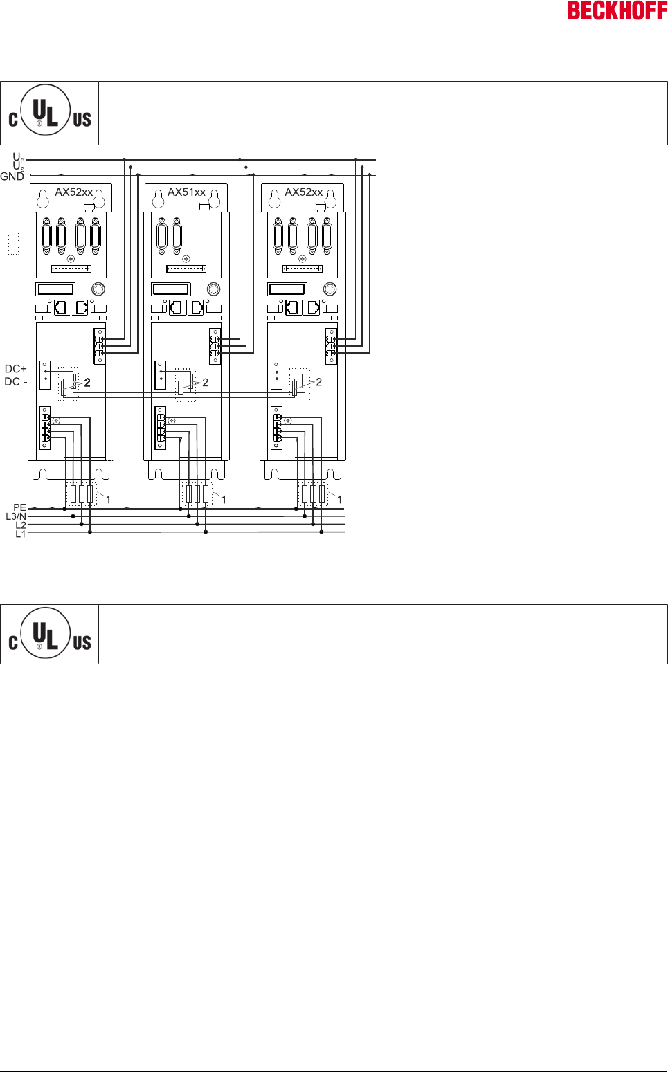
Electrical installation
Servo Drives AX500054 Version: 2.4
9.1.4 UL drive system - configuration example
Drive system with UL approval!
The following illustration shows a possible configuration example. Before implementation,
please contact your UL approval body and discuss further necessary boundary conditions.
Legend:
1 = UL fuse (480 VAC)
2 = UL fuse (700 VAC / 800 VDC) e.g. Ferrule FWP from Cooper-Bussmann
Fuse holders with UL approval
Note when using UL fuses that the necessary fuse holders also have to carry UL approval.
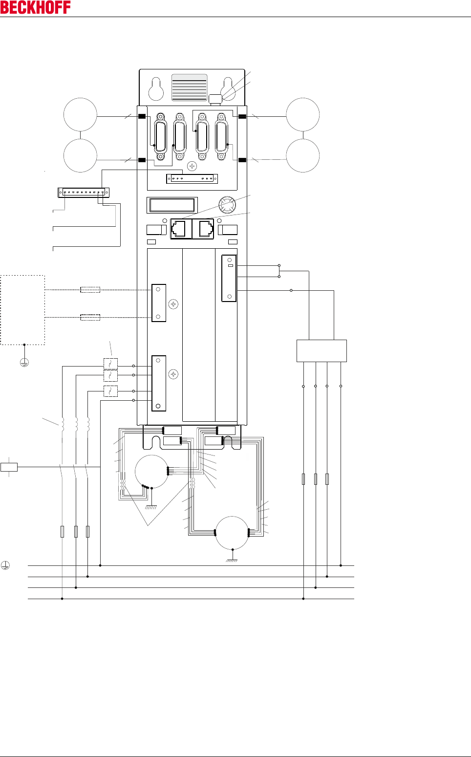
Electrical installation
Servo Drives AX5000 55
Version: 2.4
9.2 Connection example AX5101 - AX5112 and AX520x
Automation GmbH
BECKHOFFEiserstr. 5
D-33415 Verl
Phone: +49 5246 / 963-0
Type:
Serial #:
Customized #:
Power Supply:
Nominal Current:
1x100 - 3x480 VAC 50/60 Hz
2 x 3 A
Rated con. load:
5 kVA
www.beckhoff.com info@beckhoff.com
0000
000000018
AX5203-0000
X11
X12
X06
X04
X05
X02
X03
X01
X3x
X4x
X21
X22
U +
p
+24V DC
GND
U +
s
PE
L3
L2
L1
FH1
FH2
FH3
+-
FN1 FN2 FN3
PE
L3
L2
L1
FB1
FB2
Motor
DC-
DC+
X13
X23
X14
X24
U
V
W
PE
A 5101 - AX5112 - AX520xX
Motor
T- / OCT
T+
PE
B-
B+
/ OCT
T- / OCT
T+ / OCT
PE
B-
B+
U
V
W
PE
X11
PE
Encoder
Sin/Cos
Resolver
Encoder
Sin/Cos
Resolver
Channel
A
Channel
B
Motor choke
(optional)
Power supply
Break
resistor
(optional)
Sin/Cos
EMC-Filter (C2)
(optional)
Optional: Second power supply
Optional: Slot for safety card
Optional: Slot for expansion
cards
Incoming EtherCAT line
Outgoing EtherCAT line
Output voltage (U 24 V +)
p DC
Output voltage GND (-)
Input 7 or output (U 24 V +)
p DC
Main chokes
(optional)
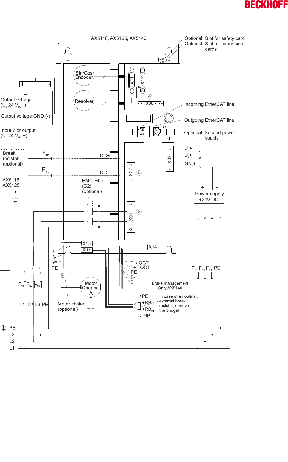
Electrical installation
Servo Drives AX500056 Version: 2.4
9.3 Connection example AX5118 - AX5125 and AX5140
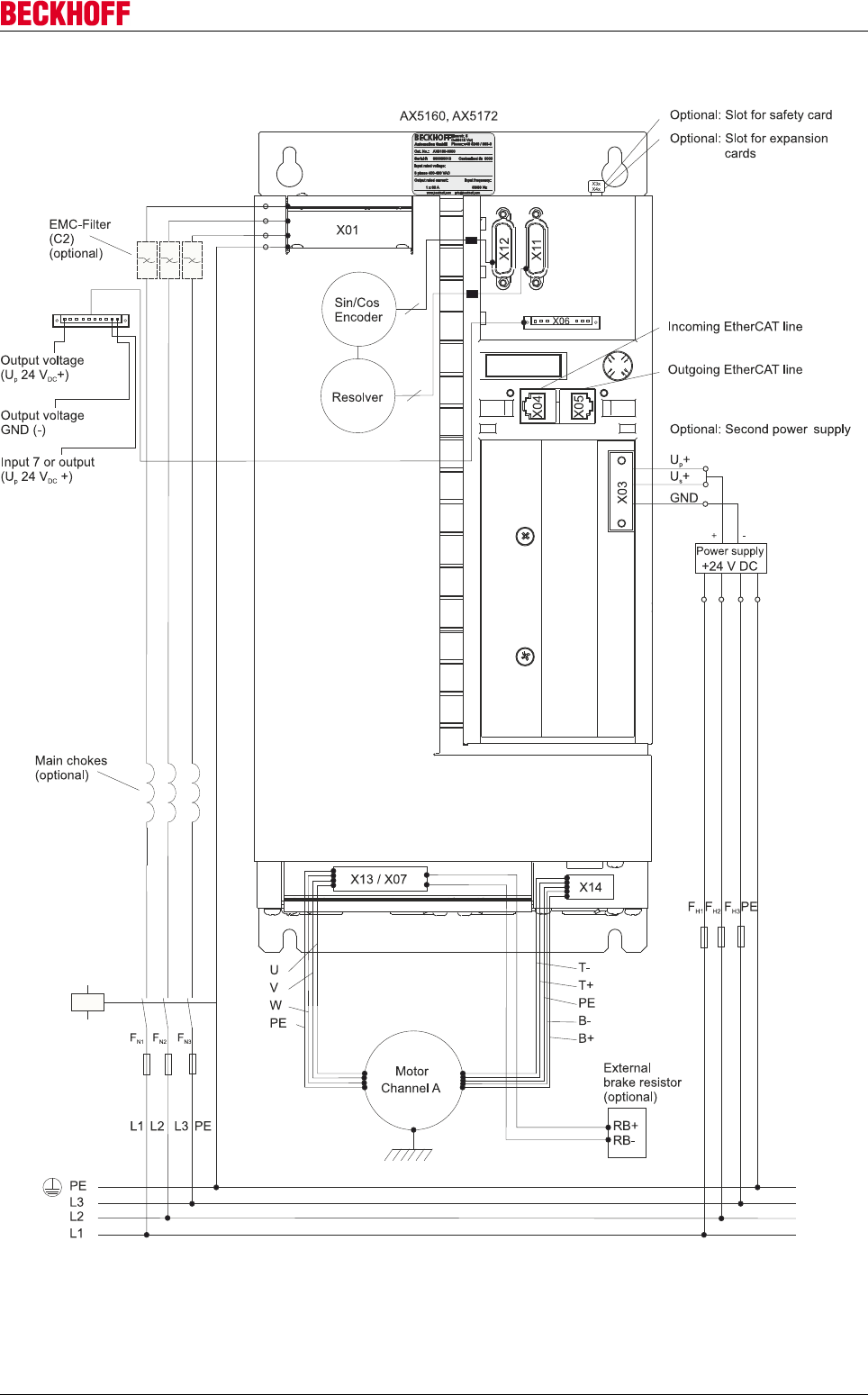
Electrical installation
Servo Drives AX5000 57
Version: 2.4
9.4 Connection example AX5160 - AX5172
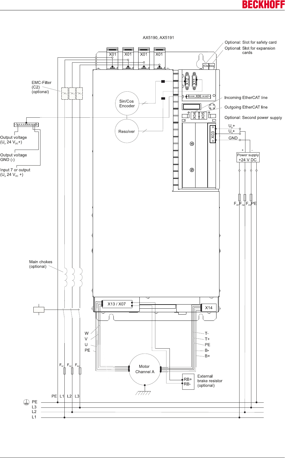
Electrical installation
Servo Drives AX500058 Version: 2.4
9.5 Connection example AX5190 - AX5191
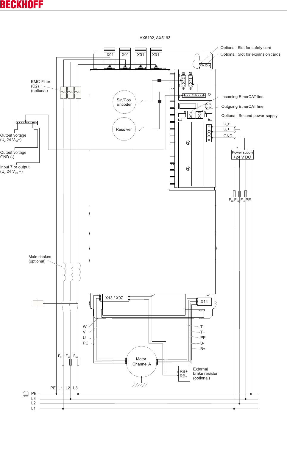
Electrical installation
Servo Drives AX5000 59
Version: 2.4
9.6 Connection example AX5192 - AX5193
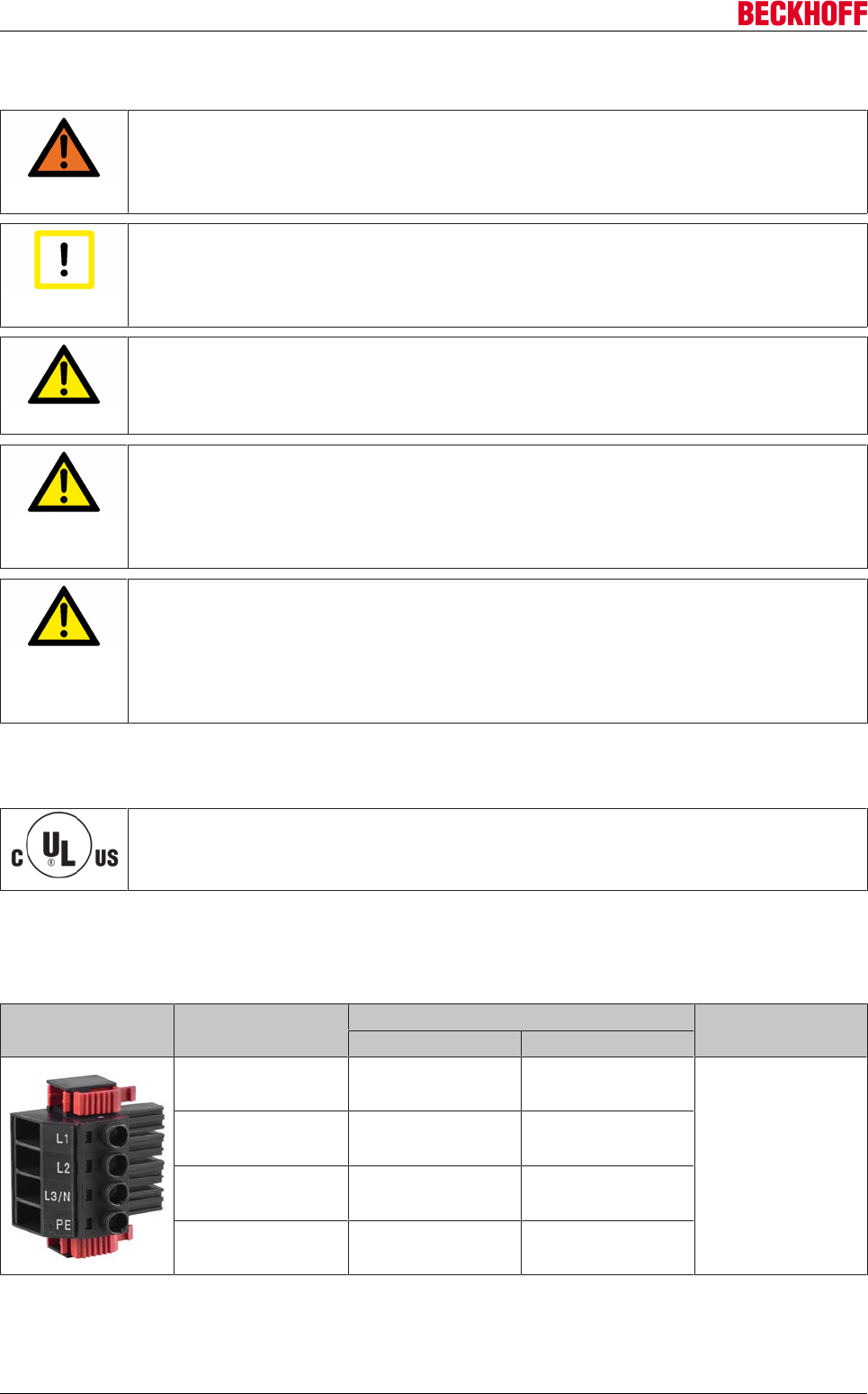
Electrical installation
Servo Drives AX500060 Version: 2.4
9.7 Power supply (1.5 A - 40 A devices)
WARNING
Caution - Risk of injury!
The electrical installation must be carried out by a qualified electrician. Before installing and
commissioning AX5000 servo drives please read the safety notes in the foreword of this
documentation.
Attention
Destruction of the AX5000!
The connection sequence of the devices is not arbitrary. The total rated current of the de-
vice must decrease from the power supply. The order "AX5112-AX5106-AX5201-AX5103"
is correct; the order "AX5201-AX5112-AX5203" is wrong.
CAUTION
Personal injuries!
Note the total current of the connected devices. According to CE the current carrying ca-
pacity of power busbars is limited to 85 A.
CAUTION
Personal injuries!
Please ensure that the connection line for the AX5901 supply module is adequately dimen-
sioned. The dimensioning depends on the total rated current and must comply with EN
60204-1. The connector plugs are designed for a maximum conductor cross-section of 25
mm2. A 3-phase connection must be used if the total rated current exceeds 9 A.
CAUTION
Personal injuries!
To set up a drive system without AX5901 supply module and AX bridge please note the fol-
lowing: The connector plugs of the wide voltage input are designed for a maximum current
of 41 A and a maximum conductor cross-section of 6 mm2. The cable configuration must
comply with the requirements specified in DIN VDE 0298 Part 4 / 2003-08 and EN 60204-1.
Avoid phase reversal between the devices!
9.7.1 X01: Main supply connection
UL Listing
It is essential to observe chapter "Guidelines and Standards" if you wish to operate an
AX5000 in an economic area that requires a UL-Listing.
Voltage systems ranging from single-phase 100 VAC to three-phase 480 VAC can be connected to the wide
voltage input of the AX5000 . In single-phase systems the mains phase is connected to terminal point L1 and
the neutral conductor to terminal point L3/N.
Terminal point Connection Tightening torque
3-phase 1-phase
L1 Phase L1 Phase L1
0,5 - 0,6 Nm
L2 Phase L2 not used
L3/ N Phase L3 Neutral conductor
PE Protective conductor Protective conductor
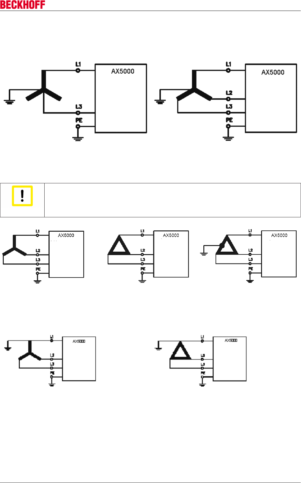
Electrical installation
Servo Drives AX5000 61
Version: 2.4
Connection to the standard mains supply (TT / TN) with earthed centre
Single phase 100 -10% .- 240 +10% VAC, 50/60 Hz Three phase 100 -10% .- 480 +10% VAC, 50/60 Hz
Connection to a IT-mains supply (100 - 240 V) without isolating transformer
Attention
EMC Act in europe!
Due to electromagnetic emission, in Europe the AX5000 must be operated in conjunction
with an isolating transformer
Connection to other mains types (100 - 240 V) without isolating transformer
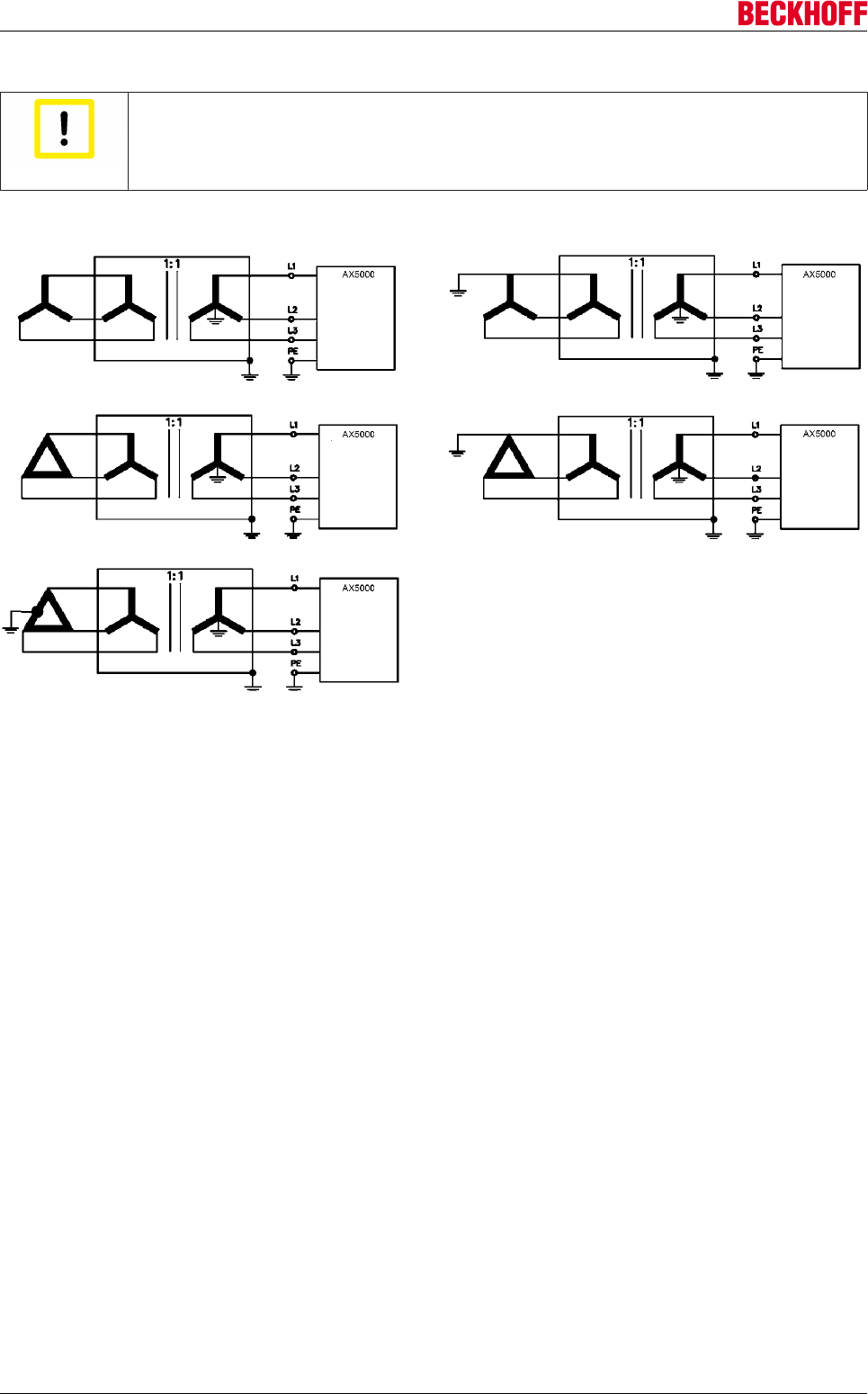
Electrical installation
Servo Drives AX500062 Version: 2.4
Connection to other mains types (100 - 480 V) with isolating transformer
Attention
Destruction of the AX5000!
For asymmetrically earthed or non-earthed 100...480 V mains an isolating transformer must
be used.
100 - 480 V Isolating transformer 240 - 480 V Isolating transformer
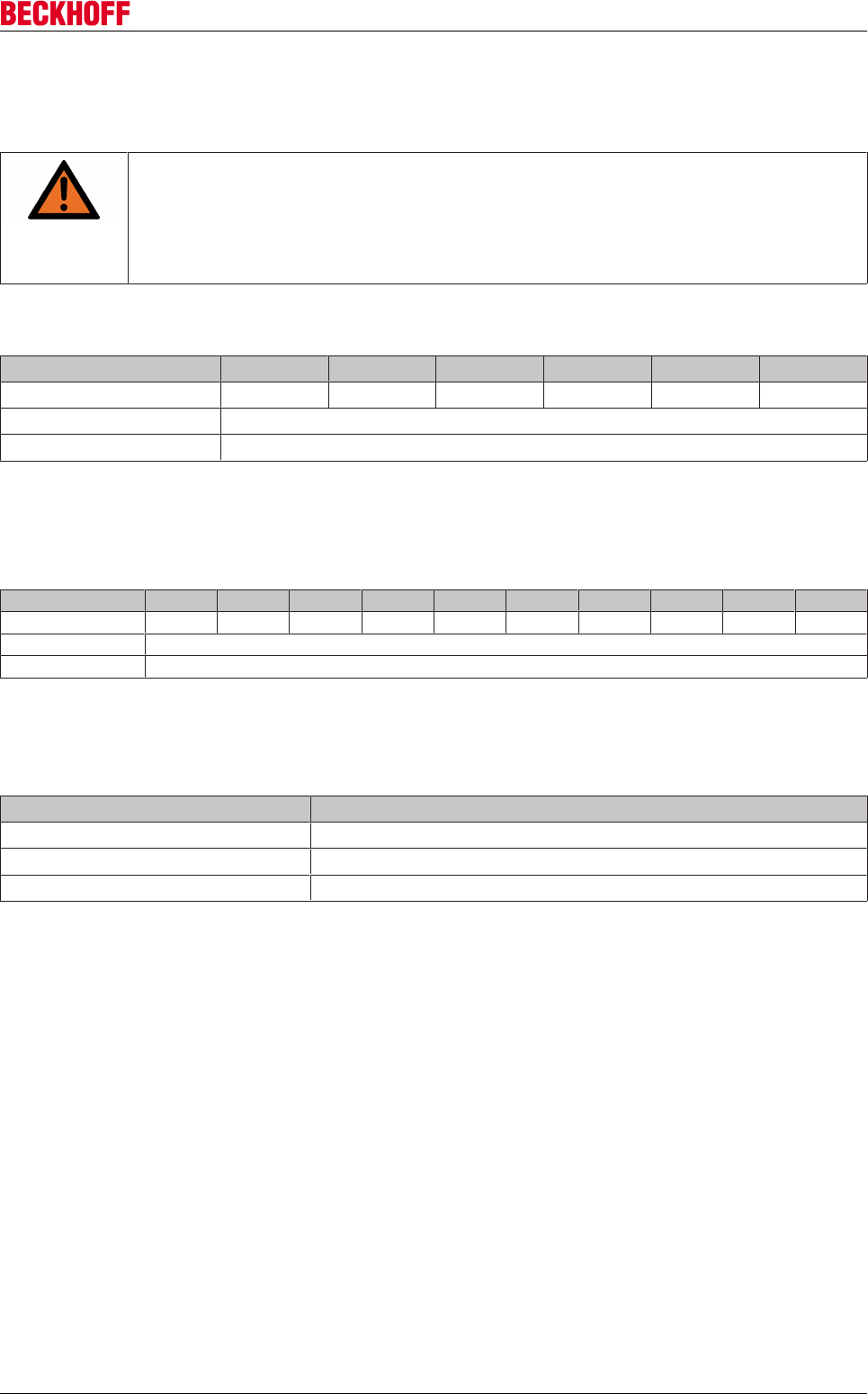
Electrical installation
Servo Drives AX5000 63
Version: 2.4
9.7.2 Fuse protection
External protection, CE-compliant
WARNING
Fire hazard due to overload of the connection cable!
• The following data refer to stand-alone devices. Please note the total current of all con-
nected devices in a multi-axis system.
• The recommended fuses are designed for line protection. The servo drives feature inte-
grated self-protection.
Single-phase:
AX5101 AX5103 AX5106 AX5201 AX5203 AX5206
AC supply *) 10 AT 10 AT 16 AT 10 AT 16 AT 20 AT
24 V supply 5 AT
Brake resistor electronic
*) Application class "gG" mains fuses according to IEC 60269 or "C" type automatic circuit-breakers must be
used.
Three-phase:
AX5101 AX5103 AX5106 AX5112 AX5118 AX5125 AX5140 AX5201 AX5203 AX5206
AC supply *) 6 AT 6 AT 10 AT 20 AT 35 AT 35 AT 50 AT 10 AT 10 AT 20 AT
24 V supply 5 AT
Brake resistor electronic
*) Application class "gG / gL" mains fuses according to IEC 60269 or "C" type automatic circuit-breakers
must be used.
Internal protection, CE-compliant
Circuit Fuse
24 V system voltage 3.4 AF
24 V peripheral voltage electronic
Brake resistor electronic
Electrical installation
Servo Drives AX500064 Version: 2.4
External protection, UL-compliant
The integrated protection against short circuit is no substitute for the external mains protection. The mains
protection must comply with the manufacturer's specification and the national and international regulations
and laws.
Can be used in power supply systems with a maximum current carrying capacity of 18000 A at 480 V.
Single-phase:
AX5101 AX5103 AX5106 AX5201 AX5203 AX5206
AC supply (max.) *) 6 A 12 A 20 A 12 A 20 A 20 A
24 V supply (max.) 3 A
Brake resistor electronic
*) UL-approved mains fuses of class "RK5" must be used.
Three-phase:
AX5101 AX5103 AX5106 AX5112 AX5201 AX5203 AX5206
AC supply (max.) *) 6 A 12 A 20 A 20 A 12 A 20 A 20 A
24 V supply (max.) 3 A
Brake resistor electronic
*) UL-approved mains fuses of class "RK5" must be used.
AX5112!
Protection through UL-approved fuses of class "RK5" with a rated current of 20 A and 480
V min.
Internal protection, UL-compliant
Circuit Fuse
24 V system voltage 3.4 AF
24 V peripheral voltage electronic
Brake resistor electronic
External drive system protection
Rule of thumb: Determine the total rated device currents, multiply with the correction factor
and round up to the next higher standard level.
Sample: 1 x AX5103 + 2 x AX5201 + 2 x AX5203
3 A + 6 A + 12 A = 21 x 1.1 = 23.1 A --> selected 25 A
Special requirements for a drive system
Please consult our Application Department with respect to the special requirements for a
drive system with UL approval.
Residual current circuit breaker
Servo drives with built-in mains filters generate a small leakage current (fault current) due to the capacitors in
the filter. This fault current is responsible for malfunctions in standard residual current circuit breakers. For
this reason so-called AC/DC sensitive residual current circuit breakers must be used, which also take into
account DC currents.
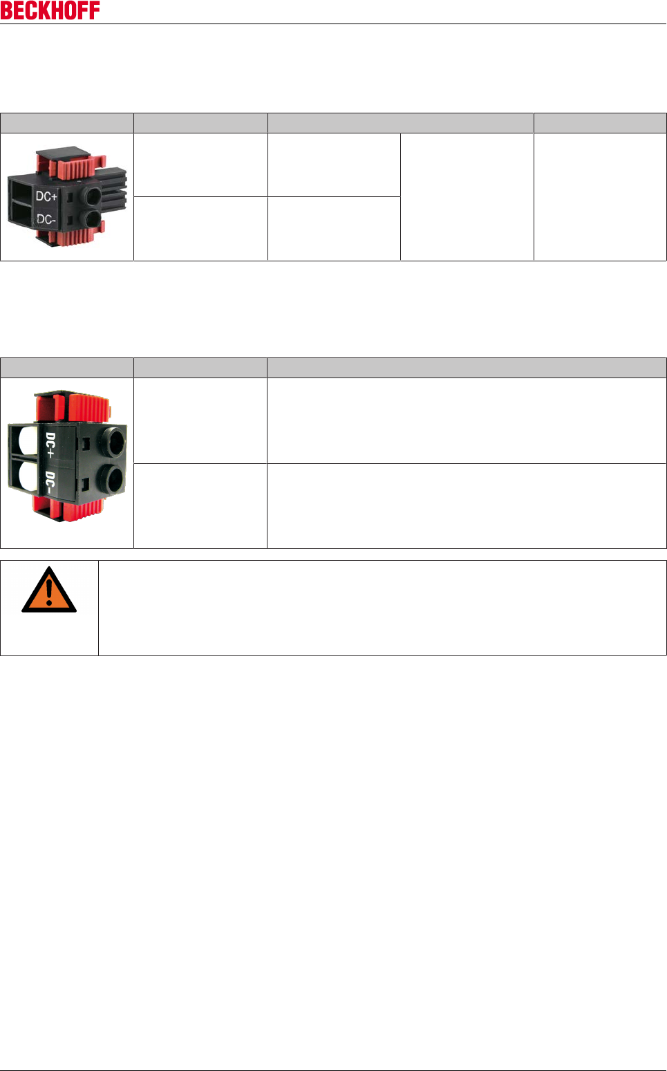
Electrical installation
Servo Drives AX5000 65
Version: 2.4
9.7.3 X02: DC Link (AX5101 - AX5125 und AX520x)
DC link coupling or external brake resistor is possible via terminal X2.
Terminal point Connection Tightening torque
DC+ DC link +
External brake
resistor
0,5 - 0,6 Nm
DC- DC link -
9.7.4 X02: DC Link (only AX5140)
Via terminal X2 a DC link coupling can be configured. Don´t connect a brake resistor under circumstances!
Terminal point Connection
DC+ DC link +
DC- DC link -
WARNING
Serious risk of injury through high electrical voltage!
890 V DC voltage at the DC link terminals X02. Once the device has been switched off
dangerous voltage will still be present for a further 5 minutes. Only remove the connector if
you wish to configure a drive system with the AX bridge. Only remove the white hexagonal
plug if the terminal points are to be rewired.
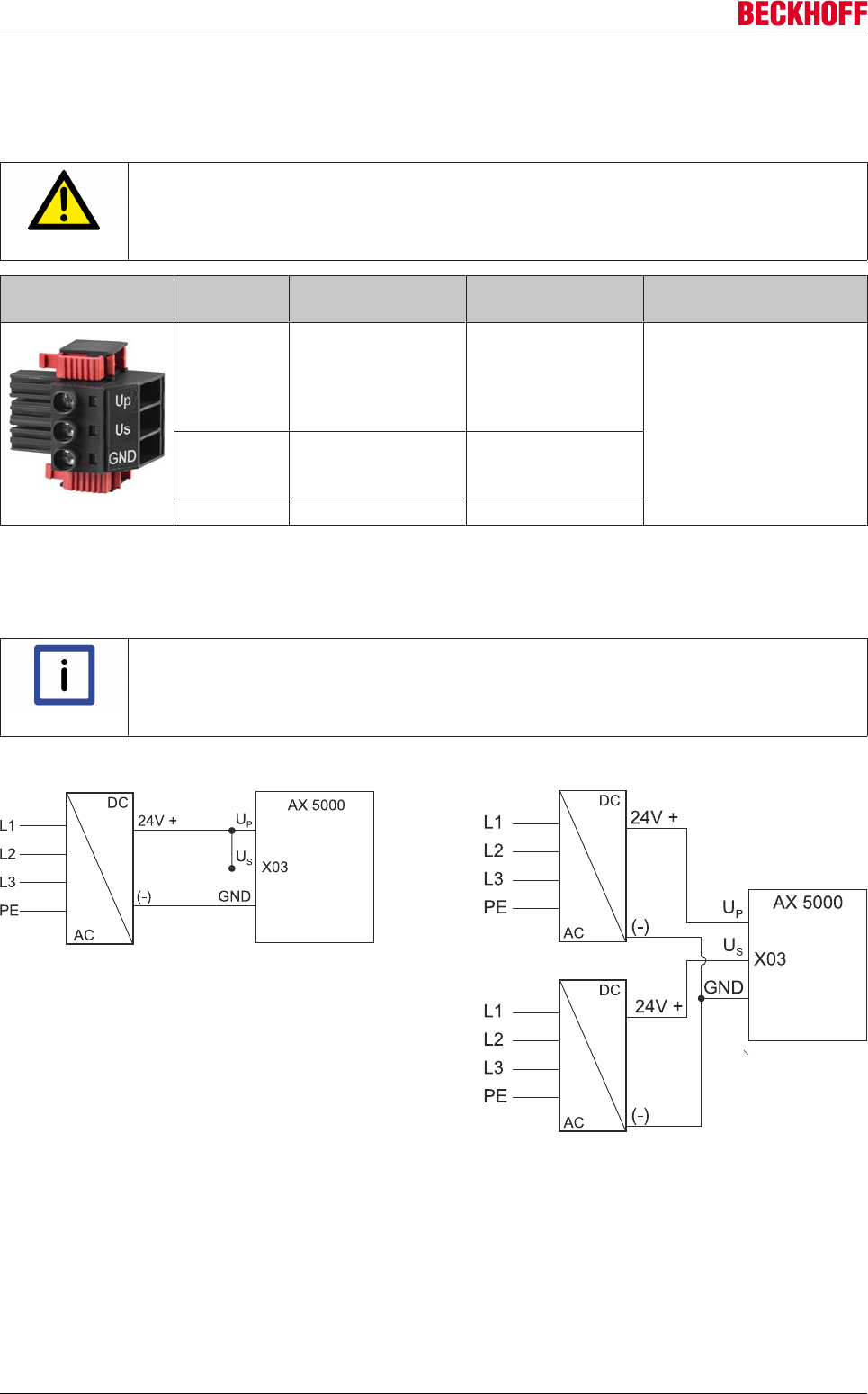
Electrical installation
Servo Drives AX500066 Version: 2.4
9.7.5 X03: 24 VDC supply
System and peripheral voltage for the servo drive is supplied via connector X3. The supply is based on two
channels in order to offer an option to separate between motor stopping brakes and control electronics.
CAUTION
Safe operation!
The voltage tolerances must be taken into account when connecting motors with stopping
brake.
Terminal
point
Connection Current consump-
tion
Tightening torque
Up 24 VDC ±10% (depending on the
motor holding brake) -
peripheral voltage
(e.g. separate brake
supply)
Depending on the
connected
consumers (see X06
and X14, X24) 0.5 – 0.6 Nm
Us 24 VDC-15% + 20% -
system supply
voltage
-12 A = 0.4 A – 0.8 A
18 A - 25 A = 1.1 A
40 A = 1.6 A
GND GND
Connection to the standard mains supply 24 VDC (X03)
The 24 VDC connection "X03" is used for supplying the control electronics and periphery with DC voltage.
The control electronics and the periphery can be supplied separately with two different voltage sources.
Note
If one power supply unit is used for the 24 VDC power supply, the connections US and UP
must be bridged, in order to ensure that both the control electronics and the periphery are
supplied.
Supply via one or two power supply units
9.7.6 Safe system stop in the event of power failure
A power failure can lead to uncontrolled idling of the drive axes: linear axis or lifting axes would hit the limit
stop unbraked. The 24 VDC supply of the AX5000 has two channels, so that separate power supplies can be
used for the control electronics and the brake control. This enables the supply voltage for the control
electronics to be buffered via the UPS of the Industrial PCs until all axes were stopped safely.
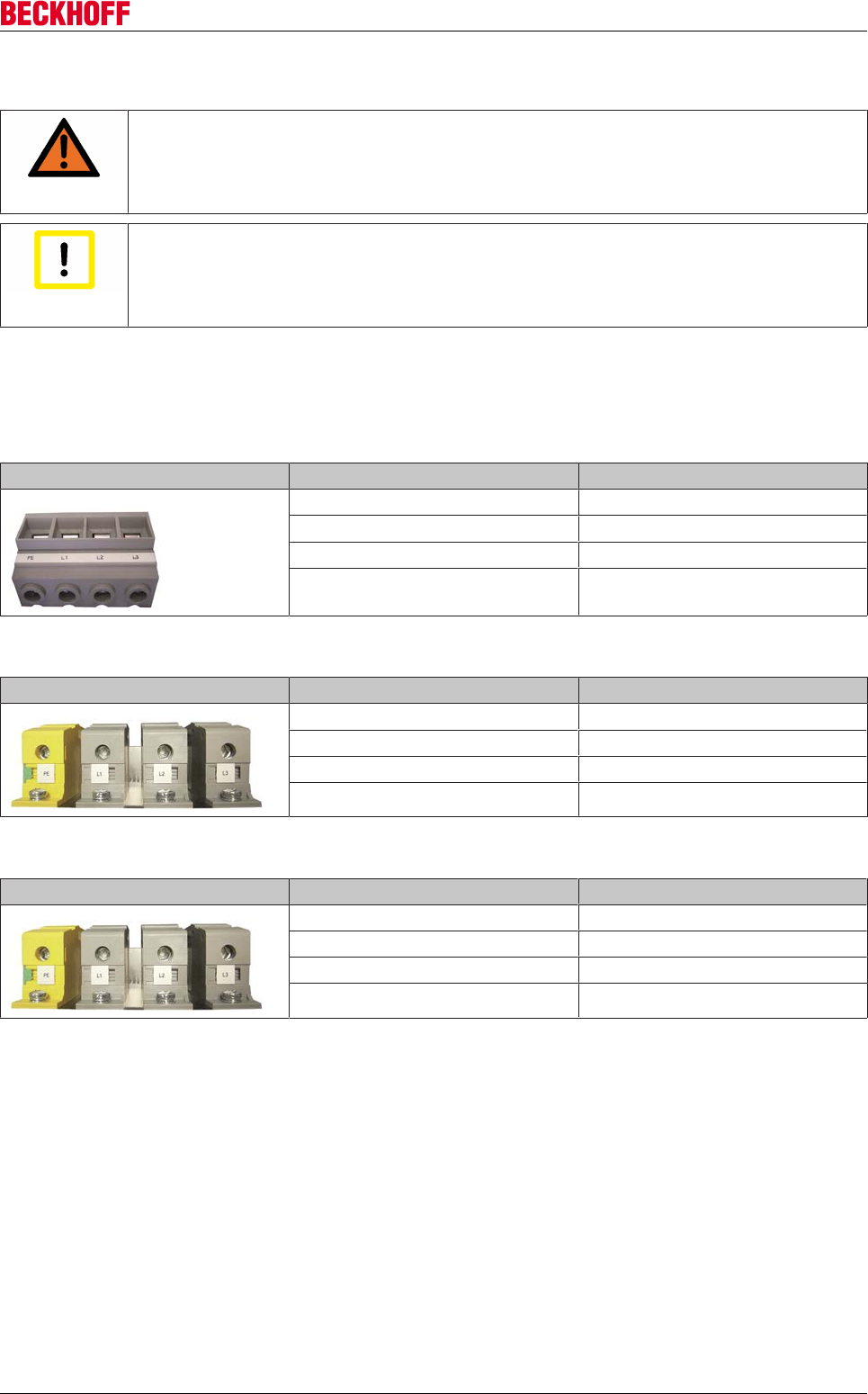
Electrical installation
Servo Drives AX5000 67
Version: 2.4
9.8 Power supply (60 A - 170 A devices)
WARNING
Caution - Risk of injury!
The electrical installation must be carried out by a qualified electrician. Before installing and
commissioning AX5000 servo drives please read the safety notes in the foreword of this
documentation.
Attention
Destruction of the AX5000!
The connection sequence of the devices is not arbitrary. The total rated current of the de-
vice must decrease from the power supply. The order "AX5112-AX5106-AX5201-AX5103"
is correct; the order "AX5201-AX5112-AX5203" is wrong.
9.8.1 X01 - Voltage input
AX5160 and AX5172
Figure Terminal point Connection
L1 Phase L1
L2 Phase L2
L3 Phase L3
PE Protective conductor
AX5190 and AX5191
Figure Terminal points Connection
L1 Phase L1
L2 Phase L2
L3 Phase L3
PE Protective conductor
AX5192 and AX5193
Figure Terminal points Connection
L1 Phase L1
L2 Phase L2
L3 Phase L3
PE Protective conductor
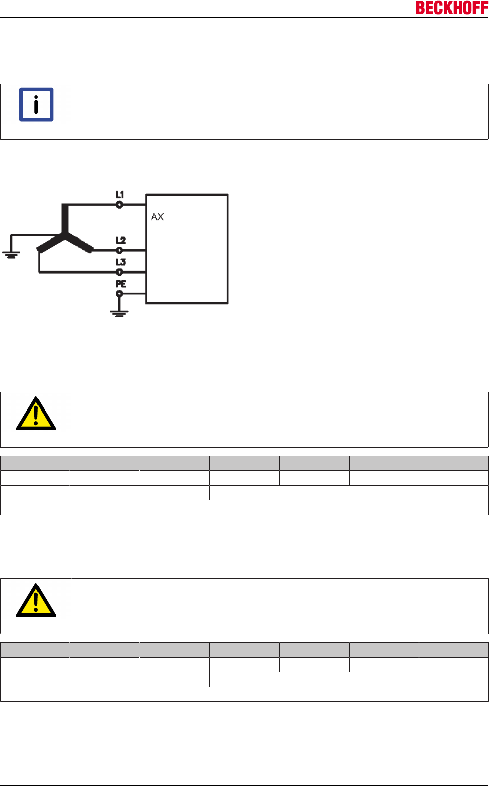
Electrical installation
Servo Drives AX500068 Version: 2.4
Mains supply connection (X01)
The servo drives of the AX5000 series are equipped with a wide voltage input „X01“ and can be connected
to voltage systems three-phases 400 VAC-10% - 480 VAC+10%.
Note
Connection to the standard mains supply (TT/TN) with earthed centre is described below.
Connections to other supply systems are not permissible.
Three-phase 400-10% - 480+10% VAC
9.8.2 Fusing
External protection for individual devices, CE-compliant
CAUTION
Fire hazard through short circuit!
The recommended fuses are designed for line protection. The servo drives feature inte-
grated self-protection.
Fusing AX5160 AX5172 AX5190 AX5191 AX5192 AX5193
AC supply*) 80 AT 100 AT 125 AT 160 AT 200 AT 224 AT
24 V supply 4 AT 10 AT
Brake resistor electronic
*)Application class „gG“ mains fuses according to IEC 60269 or „C“ type automatic circuit breakers must be
used.
External protection for individual devices, UL-compliant
CAUTION
Fire hazard through short circuit!
The recommended fuses are designed for line protection. The servo drives feature inte-
grated self-protection.
Fusing AX5160 AX5172 AX5190 AX5191 AX5192 AX5193
AC supply*)
24 V supply 4 AT 10 AT
Brake resistor electronic
*)Mains fuses according to type “RK5” min. 480 V must be used.
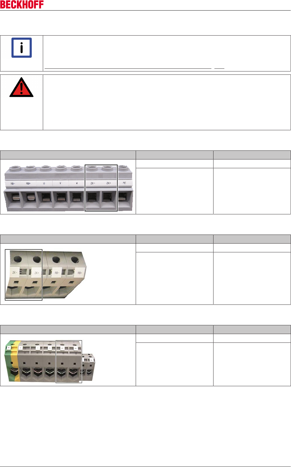
Electrical installation
Servo Drives AX5000 69
Version: 2.4
9.8.3 X02: DC link
Note
DC link AX5000 (60 A -170 A devices)!
When establishing a DC link connection (only for 60 A – 170 A devices!), it is essential to
follow the chapter:
"Connection example – DC link group (60 A - 170 A devices)". [}50]
DANGER
Serious risk of injury through high electrical voltage!
Due to the DC link capacitors, the DC link terminal points "DC+ and DC-" and "RB+ and
RB-" may be subject to dangerous voltages exceeding 875 VDC, even after the servo drive
was disconnected from the mains supply.
After disconnection, wait for 15 minutes (AX5160/AX5172), 30 minutes (AX5190/AX5191)
or 45 minutes (AX5192/AX5193) and measure the voltage at the DC link-terminal points
DC+ and DC-. The device is safe once the voltage has fallen below 50 V.
AX5160 - AX5172
Figure Terminal point Connection
DC + DC link +
DC - DC link -
AX5190 – AX5191
Figure Terminal point Connection
DC + DC link +
DC - DC link -
AX5192 – AX5193
Figure Terminal point Connection
DC + DC link +
DC - DC link -
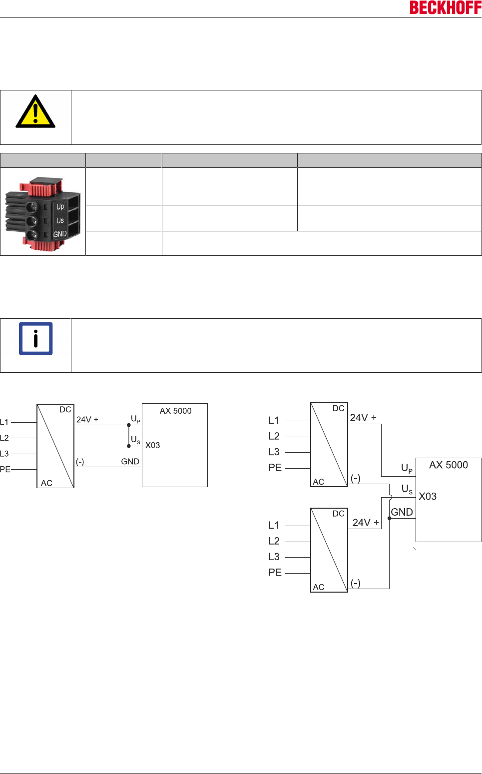
Electrical installation
Servo Drives AX500070 Version: 2.4
9.8.4 X03: 24 VDC supply
System and peripheral voltage for the servo drive is supplied via connector X3. The supply is based on two
channels in order to offer an option to separate between motor stopping brakes and control electronics.
CAUTION
Safe operation!
The voltage tolerances must be taken into account when connecting motors with stopping
brake.
Terminal point Connection Current consumption
Up 24 VDC ±10% (depending on the motor holding
brake) - peripheral voltage (e.g.
separate brake supply)
Depending on the connected consumers
(see X06 and X14)
Us 24 VDC-15% + 20% - system
supply voltage
60A – 72A = 3A
90A – 170A = 10A
GND GND
Connection to the standard mains supply 24 VDC (X03)
The 24 VDC connection "X03" is used for supplying the control electronics and periphery with DC voltage.
The control electronics and the periphery can be supplied separately with two different voltage sources.
Note
If one power supply unit is used for the 24 VDC power supply, the connections US and UP
must be bridged, in order to ensure that both the control electronics and the periphery are
supplied.
Supply via one or two power supply units
9.8.5 Safe system stop in the event of power failure
A power failure can lead to uncontrolled idling of the drive axes: linear axis or lifting axes would hit the limit
stop unbraked. The 24 VDC supply of the AX5000 has two channels, so that separate power supplies can be
used for the control electronics and the brake control. This enables the supply voltage for the control
electronics to be buffered via the UPS of the Industrial PCs until all axes were stopped safely.

Electrical installation
Servo Drives AX5000 71
Version: 2.4
9.9 Leakage currents
When operating servo drives, operationally related leakage currents occur in various frequency ranges
(capacitive): In addition, it is possible for a smooth DC residual current (ohmic) to be produced after the
rectifier. These currents would prevent a residual current circuit breaker (RCCB or RCD) of the type A or AC
from tripping. In the event of a fault, therefore, it would be possible for dangerous voltages to be present on
the housing parts. For 3-phase applications the statutory regulations in different countries (please check
whether your country is affected) require the use of AC/DC-sensitive RCDs. These should have a rated
residual current of ≤ 300 mA. In order to be able to meet these requirements it is necessary to know or
calculate the expected leakage currents.
Formulas
The leakage current level depends on the fixed leakage currents, the motor cable length and the supply
voltage. The following formulas were determined empirically.
Note
Calculation basis
The values for the leakage current calculated with the equations are valid only if:
• original Beckhoff motor cables are used and
• shielding and grounding concepts are adhered to
• In addition it should be noted that the calculated leakage current value is not exact but
merely reflects the maximum expected value, with associated dispersion.
Note
Composition of the max. total leakage current
The max. total leakage current is composed of:
• a device-dependent fixed part with 50 Hz (single-phase feed) or 150 Hz (three-phase
feed)
• plus a variable part that depends on the motor cable length and clock frequency. If no
other specifications are applied, the clock frequency is around 8 kHz.
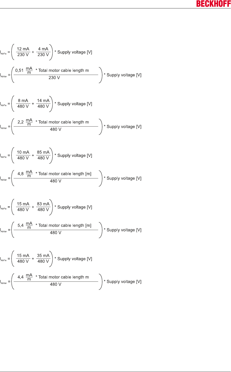
Electrical installation
Servo Drives AX500072 Version: 2.4
Leakage currents for individual devices
ILCdevice = ILCfix + ILCvar
AX5000 up to 12 A – single-phase connection, leakage current in [mA]:
AX5000 up to 12 A – three-phase connection, leakage current in [mA]:
AX5118 - three-phase connection, leakage current in [mA]:
AX5125 - three-phase connection, leakage current in [mA]:
AX5140 - three-phase connection, leakage current in [mA]:
The total leakage current is composed of the sum of the individual device leakage currents:
ILCtotal = ILCdevice1 + ILCdevice2 +...+ ILCdevicen
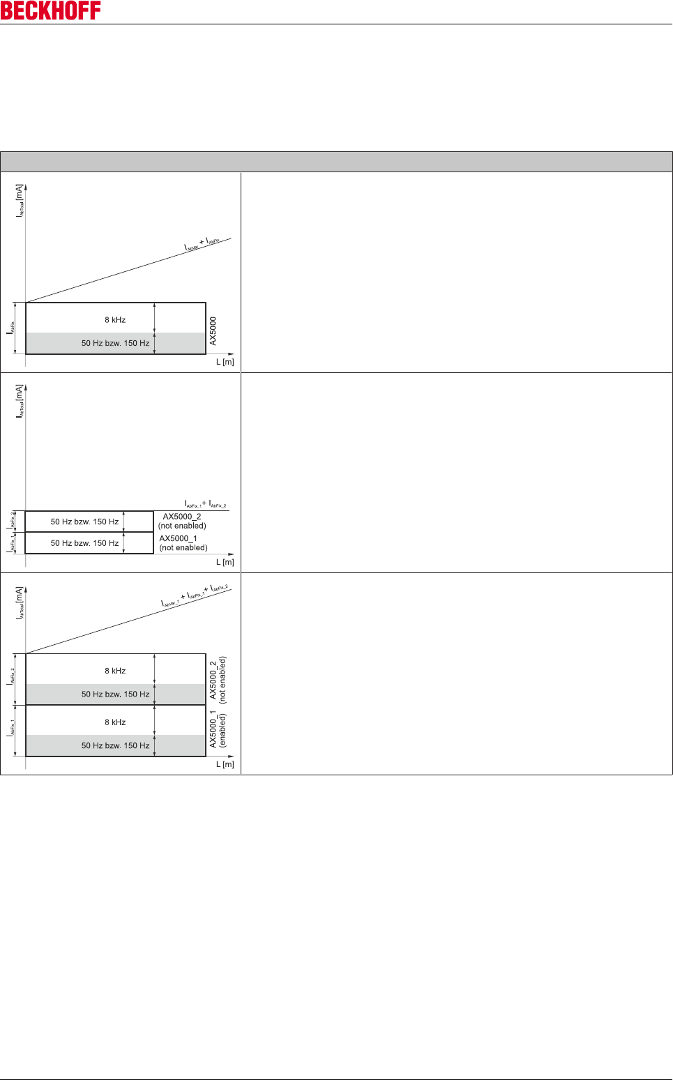
Electrical installation
Servo Drives AX5000 73
Version: 2.4
Leakage currents in a DC link
If several devices are connected via a DC link, only the fixed leakage currents for 50 Hz or 150 Hz are
present, as long as no axis is enabled. As soon as an axis is released, the complete fixed leakage currents
(50 Hz or 150 Hz) are present and additionally a fixed portion of 8 kHz with a motor cable length of 0 m. The
following diagrams illustrate the individual leakage current components:
Sample
1 x AX5000 (enabled) without DC link
ILCtotal = ILCvar + ILCfix
2 x AX5000 (not enabled) in DC link
IABtotal = IABfix_1 + IABfix_2
1 x AX5000 (enabled) + 1 x AX5000 (not enabled) in DC link
IABtotal = IABvar_1 + IABfix_1 + IABfix_2
If the AX5000_2 is also enabled the equation is as follows:
IABtotal = IABvar_1 + IABvar_2 + IABfix_1 + IABfix_2
Influence of the motor chokes
Motor chokes are used in order to protect the power semiconductors and the motors through lower voltage
edges and therefore reduced peak values of the commutation or leakage currents. However, the reduction in
voltage edges has no influence on the RMS value of the leakage currents. Since this is precisely what an
RCD invariably assesses, motor chokes have no positive influence here.
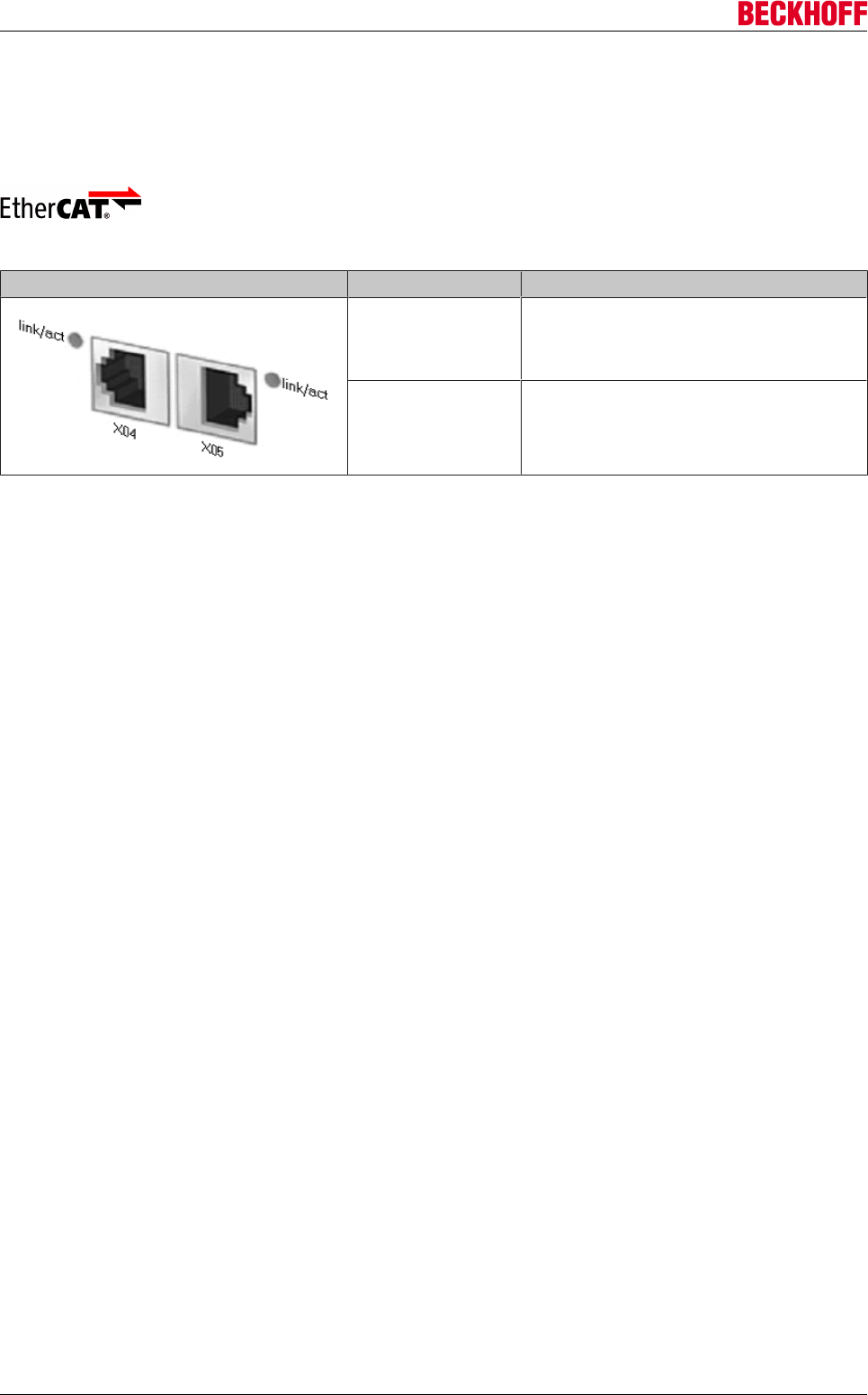
Electrical installation
Servo Drives AX500074 Version: 2.4
9.10 EtherCAT
9.10.1 X04, X05: EtherCAT connection
The AX5000 is integrated in the EtherCAT strand via the RJ45 sockets X04 and X05.
RJ45 Signal
X04 (IN) incoming EtherCAT line
X05 (OUT) outgoing EtherCAT line
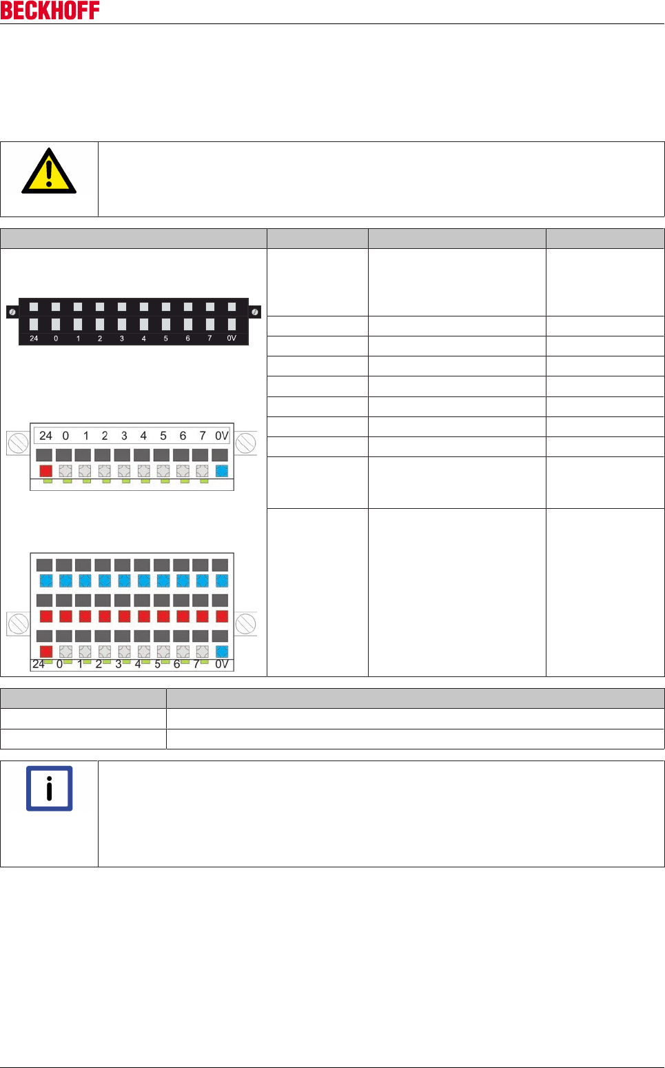
Electrical installation
Servo Drives AX5000 75
Version: 2.4
9.11 Digital I/Os
9.11.1 X06: Digital I/Os
CAUTION
Destruction of the AX5000!
This connector is not designed for external power supply. It is supplied via the 24 V supply
(periphery) of connector X03.
Terminal point Signal Output current
I/O plug connector without LEDs
ZS4500-2006
I/O plug connector with LEDs
ZS4500-2007 (optional)
ZS4500-2008 (optional)
24 Power supply for the
external sensors (switches/
initiators)
(Up 24 VDC +)
max. 1 A
0 Input 0
1 Input 1
2 Input 2
3 Input 3
4 Input 4
5 Input 5
6 Input 6
7 Input 7 or output
(configurable)
(Up 24 VDC +)
max. 0.5 A
0V GND (-)
Voltage level State
-3 V ... 5 V 0 or "false"
15 V ... 30 V 0 or "false"
Note
Configuration of the plug signal inputs:
The signal inputs of the plugs can be configured with the following functions (IDNs):
P-0-0251, P-0-0400, P-0-0401, P-0-0402, P-0-0800, P-0-0801, P-0-0802.
For further information please refer to the documentation for the
S- and P-parameters of the AX5000 servo drive series.
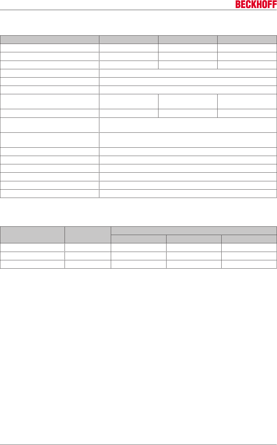
Electrical installation
Servo Drives AX500076 Version: 2.4
9.11.2 Technical data
Technical data ZS4500-2006 ZS4500-2007 ZS4500-2008
Number of terminal points 10 10 30
Signal LEDs no yes yes
Rated voltage 24 VDC 24 VDC 24 VDC
Rated current 2 A
Wire cross section 0.5mm2... 1.5 mm2
Strip length 10 mm
Dimensions (W x H x D) approx. 42mm x
10.3mm x 26.9mm
approx. 42mm x
12.7mm x 26.9mm
approx. 42mm x
20.8mm x 26.9mm
Weight approx. 10 g approx. 10 g approx. 20 g
Permissible ambient temperature
range during operation
0°C ... + 55°C
Permissible ambient temperature
range during storage
-25°C ... + 85°C
Permissible relative humidity 95%, no condensation
Vibration/shock resistance conforms to EN60068-2-6/ EN60068-2-27, EN60068-2-29
EMC immunity/emission conforms to EN 61000-6-2 / EN 61000-6-4
Protection class IP 20
Installation position variable
Approval CE, UL, CSA
9.11.3 Ordering information for I/O plug connectors
Order identifier Signal LEDs Supports the following connection types
Single-conductor Two-conductor Three-conductor
ZS4500-2006 no yes no no
ZS4500-2007 yes yes no no
ZS4500-2008 yes yes yes yes
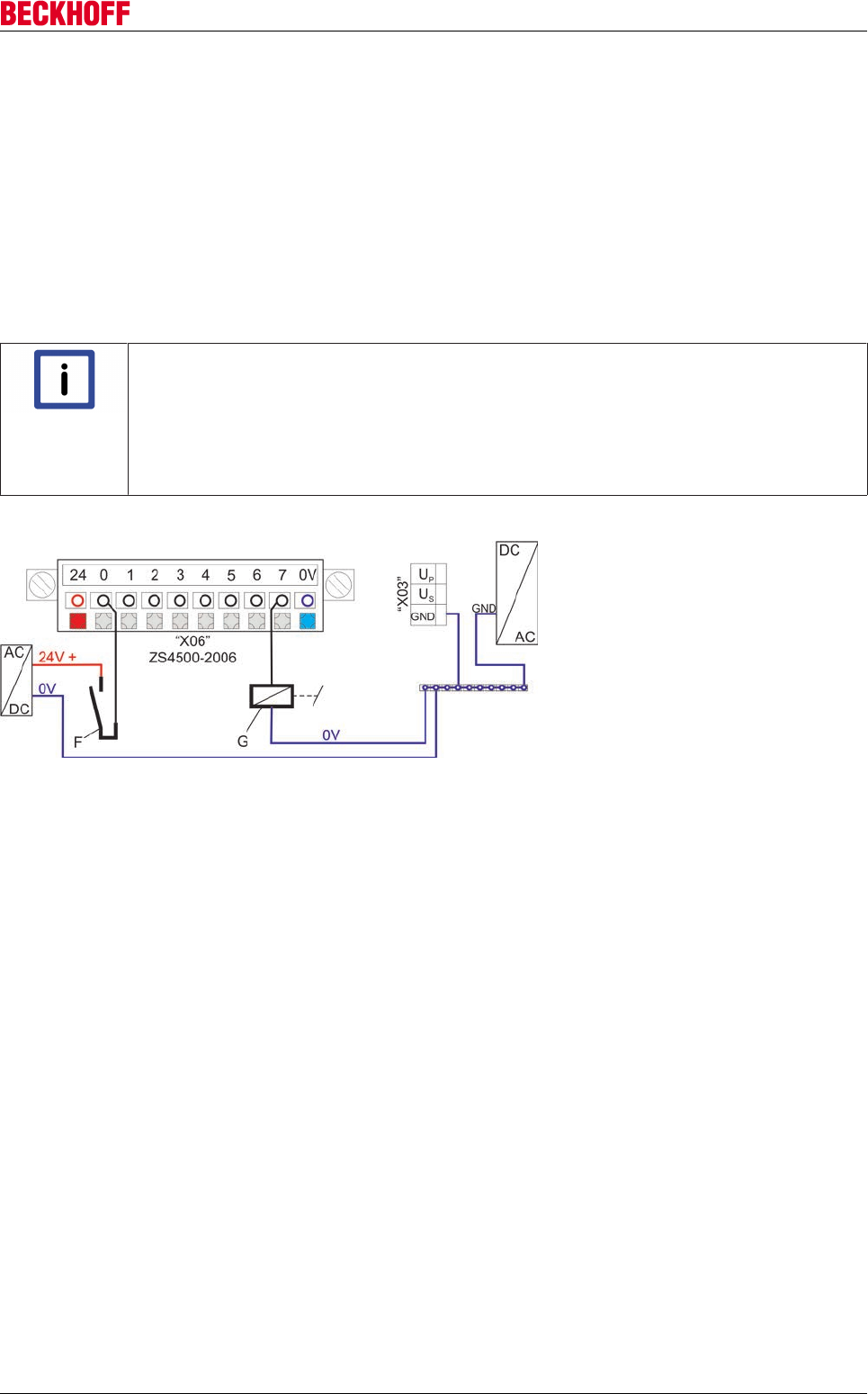
Electrical installation
Servo Drives AX5000 77
Version: 2.4
9.11.4 Connection of digital sensors/actuators
ZS4500-2006 (standard) and ZS4500-2007 (optional)
The connection type (single-conductor) in the two connectors ZS4500-2006 and ZS4500-2007 is identical.
The ZS4500-2007 is additionally equipped with LEDs. The following diagram shows the ZS4500-2006.
A sensor (F) is connected at terminal point "0" via a single-conductor connection. The 24 V supply for the
sensor is connected externally. It would also be possible to take the 24 V supply for sensor (F) directly from
terminal point "24", which would cover this option.
In this case terminal point "7" is configured as an output. The configuration is implemented on the software
side. A relay (G) is connected via a single conductor; the 0 V connection is external.
Note
Ground potential
• If sensor (F) or further initiators are supplied through a separate power supply unit, the
ground potential of the separate power supply unit must be connected with the ground
potential of terminal point "GND" of connector "X03" (24 V supply).
• The ground potential (0 V) of the relay (G) must be connected with the ground potential
of terminal point "GND" of connector "X03" (24 V supply).
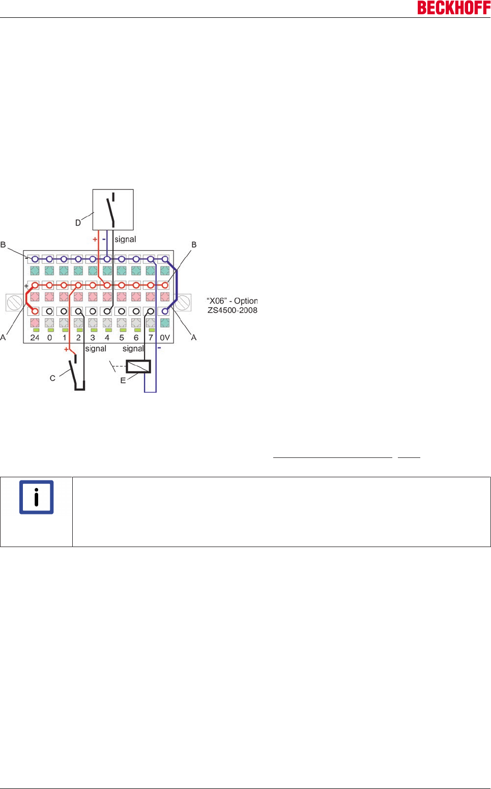
Electrical installation
Servo Drives AX500078 Version: 2.4
ZS4500-2008 (optional)
A single-, two- or three-conductor connection may be used for this connector. The diagram shows the two-
and three-conductor type. The single-conductor type matches the diagram for connector ZS4500-2006.
The terminal points at (B) are internally bridged. The two bridges (A) have to be established externally on the
plug, in order to use the terminal points.
A sensor (C) is connected at terminal point "2" via a two-conductor connection.
An initiator (D) is connected at terminal point "4" via a three-conductor connection.
In this case terminal point "7" is configured as an output. The configuration is implemented on the software
side. At this point a relay (E) is connected via a two-conductor connection.
9.12 Feedback
Information on commutation can be found in chapter 10.12: "Commutation techniques [}200]".
Information about the limit frequencies can be found under the interface descriptions.
Note
Absolute encoder
When using an absolute encoder, it must be verified before moving the axis that the feed-
back system supplies the expected position data at the distinctive positions in the travers-
ing range - ‘START’ and ‘MID’ and ‘END’ – and that these positions are retained after the
restart (Bootstrap -> OP) of the AX5000. Overflow in the traversing range must be avoided!

Electrical installation
Servo Drives AX5000 79
Version: 2.4
9.12.1 Rotational encoders
Heidenhain:
The Heidenhain company supplies feedback systems with the "EnDat 2.2" interface in 2 versions. One
version is without the analog signals (sine and cosine), one version includes the analog signal "1Vss". To
date, Beckhoff supports only EnDat 2.1 with analog signal. Since the EnDat 2.2 interface supports all of the
commands of EnDat 2.1, attention only needs to be paid to the provision of the analog signal 1Vss on the
Heidenhain feedback systems with EnDat 2.2; i.e. the Heidenhain order designation "EnDat02" must be
stated.
Type System Sin/Cos per
revolution
Supply
voltage
Interface Sampling
ECI 1118 Singleturn 16 5 V EnDat 2.1 + 1
Vpp
Inductive
ECI 1319 Singleturn 32 5 V or
7 - 10 V
EnDat 2.1 + 1
Vpp
Inductive
ECN 413 Singleturn 512 3.6 V - 14 V EnDat 2.1 + 1
Vpp
Optical
ECN 413 Singleturn 2048 3.6 V - 14 V EnDat 2.1 + 1
Vpp
Optical
ECN 1113 Singleturn 512 5 V EnDat 2.1 + 1
Vpp
Optical
ECN 1313 Singleturn 2048 5 V EnDat 2.1 + 1
Vpp
Optical
EQI 1130 Multiturn 16 5 V EnDat 2.1 + 1
Vpp
Inductive
EQI 1331 Multiturn 32 5 V or
7 - 10 V
EnDat 2.1 + 1
Vpp
Inductive
EQN 425 Multiturn 512 3.6 V - 14 V EnDat 2.1 + 1
Vpp
Optical
EQN 425 Multiturn 2048 3.6 V - 14 V EnDat 2.1 + 1
Vpp
Optical
EQN 1125 Multiturn 512 5 V EnDat 2.1 + 1
Vpp
Optical
EQN 1325 Multiturn 512 5 V EnDat 2.1 + 1
Vpp
Optical
EQN 1325 Multiturn 2048 5 V EnDat 2.1 + 1
Vpp
Optical
RCN 829 Singleturn 32768 3.6 – 5.25 V EnDat 2.2 + 1
Vpp
Optical
ROQ 425 Multiturn 512 3.6 V - 14 V EnDat 2.1 + 1
Vpp
Optical
ROQ 425 Multiturn 2048 3.6 V - 14 V EnDat 2.1 + 1
Vpp
Optical
ERN 180 incremental 1024 5 V 1 Vpp Optical
ERN 180 incremental 2048 5 V 1 Vpp Optical
ERN 180 incremental 5000 5 V 1 Vpp Optical
ERN 480 incremental 2048 5 V 1 Vpp Optical
ERM 280 incremental 1200 5 V 1 Vpp Magnetic
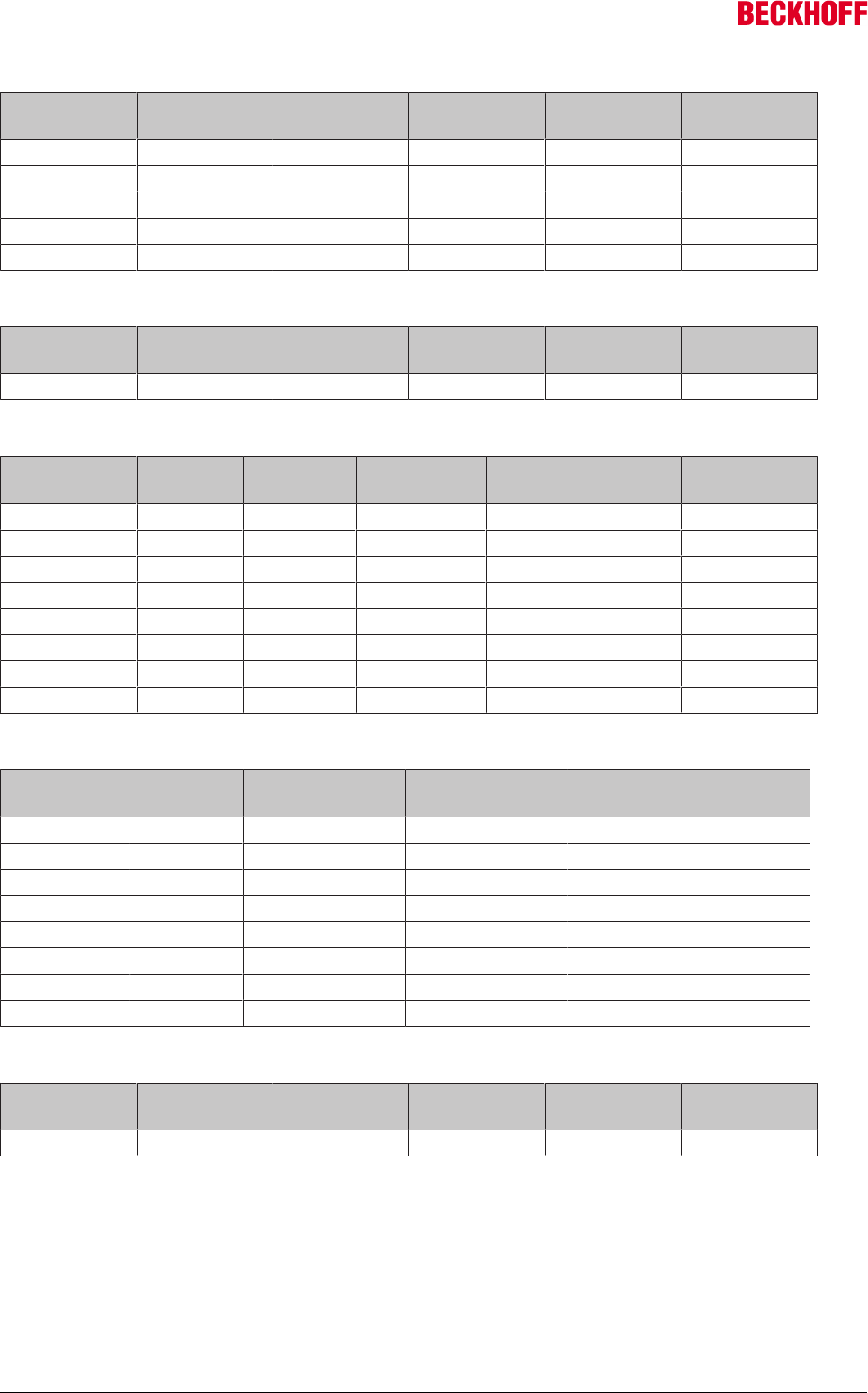
Electrical installation
Servo Drives AX500080 Version: 2.4
Hengstler:
Type System Sin/Cos per
revolution
Supply
voltage
Interface Sampling
AD 34 Singleturn 2048 5 V BiSS + 1 Vpp Optical
AD 36 Singleturn 2048 5 V BiSS + 1 Vpp Optical
AD 36 Multiturn 2048 5 V BiSS + 1 Vpp Optical
AD 58 Singleturn 2048 5 V BiSS + 1 Vpp Optical
AD 58 Multiturn 2048 5 V BiSS + 1 Vpp Optical
Kübler:
Type System Sin/Cos per
revolution
Supply
voltage
Interface Sampling
8.5853 Singleturn 2048 5 V BiSS + 1 Vpp Optical
Sick- Stegmann:
Type System Sin/Cos per
revolution
Supply
voltage
Interface Sampling
SEK 37 Singleturn 16 7 V - 12 V HIPERFACE + 1 Vpp Capacitive
SEL 37 Multiturn 16 7 V - 12 V HIPERFACE + 1 Vpp Capacitive
SEK 52 Singleturn 16 7 V - 12 V HIPERFACE + 1 Vpp Capacitive
SEL 52 Multiturn 16 7 V - 12 V HIPERFACE + 1 Vpp Capacitive
SRS 50 Singleturn 512 7 V - 12 V HIPERFACE + 1 Vpp Optical
SRM 50 Multiturn 512 7 V - 12 V HIPERFACE + 1 Vpp Optical
SKS 36 Singleturn 125 7 V - 12 V HIPERFACE + 1 Vpp Optical
SKM 36 Multiturn 125 7 V - 12 V HIPERFACE + 1 Vpp Optical
Digital rotary encoders:
Type System Resolution per
revolution
Interface Sampling
EEK 37 Singleturn 16 bit OCT Capacitive
EEL 37 Multiturn 16 bit OCT Capacitive
EKS 36 Singleturn 18 bit OCT Optical
EKM 36 Multiturn 18 bit OCT Optical
EKS 36 Singleturn 20 bit OCT Optical
EKM 36 Multiturn 20 bit OCT Optical
ERS 50 Singleturn 23 bit OCT Optical
ERM 50 Multiturn 23 bit OCT Optical
Universal rotary encoders:
Type System Sin/Cos per
revolution
Supply
voltage
Interface Sampling
1 512 5 V 1 Vpp
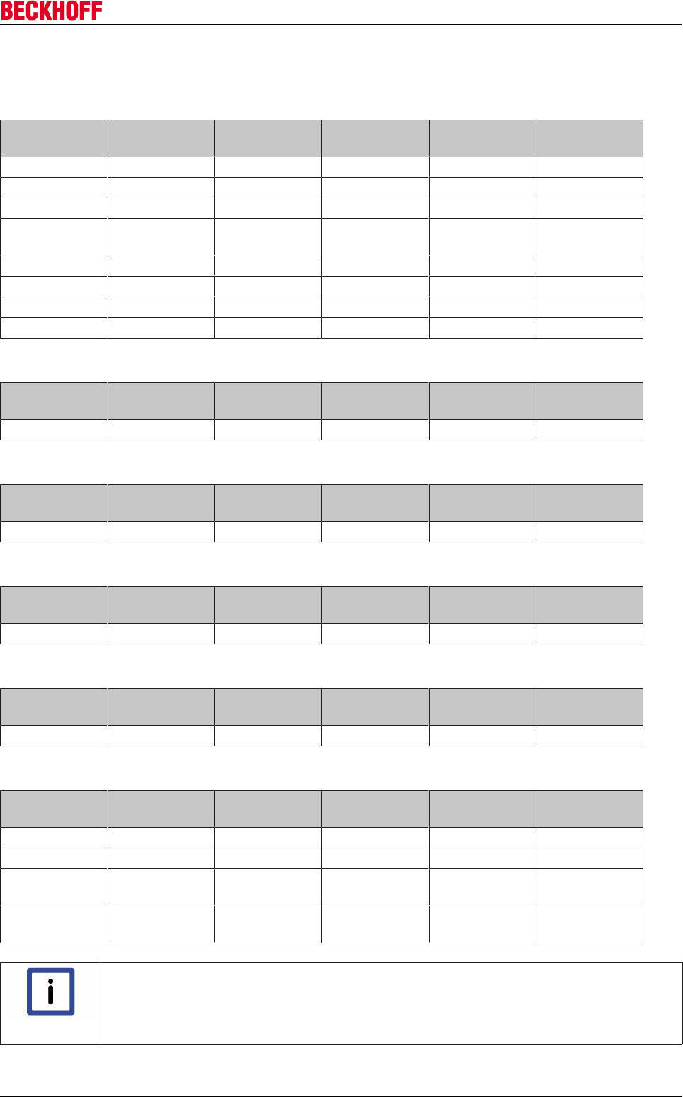
Electrical installation
Servo Drives AX5000 81
Version: 2.4
9.12.2 Linear encoders
Heidenhain:
Type System Measuring
steps
Supply
voltage
Interface Sampling
LS 388C incremental 20 µm 5 V 1 Vpp Optical
LS 486 incremental 20 µm 5 V 1 Vpp Optical
LS 487 incremental 20 µm 5 V 1 Vpp Optical
LC 483 incremental 20 µm 3.6 V – 5.25 V EnDat 2.1 + 1
Vpp
Optical
LIDA 477 incremental 20 µm 5 V 1 Vpp Optical
LIDA 483 incremental 20 µm 5 V 1 Vpp Optical
LIDA 487 incremental 20 µm 5 V 1 Vpp Optical
LIDA 287 incremental 200 µm 5 V 1 Vpp Optical
HIWIN:
Type System Measuring
steps
Supply
voltage
Interface Sampling
Magic incremental 1 mm 5 V 1 Vpp Magnetic
lika:
Type System Measuring
steps
Supply
voltage
Interface Sampling
SMS incremental 1 mm 5 V 1 Vpp Magnetic
Numerik Jena:
Type System Measuring
steps
Supply
voltage
Interface Sampling
LIA20 incremental 20 µm 5 V 1 Vpp Optical
Siko:
Type System Measuring
steps
Supply
voltage
Interface Sampling
LE100/1 incremental 1 mm 5 V 1 Vpp Magnetic
Universal linear encoders:
Type System Measuring
steps
Supply
voltage
Interface Sampling
1 incremental 20 µm 5 V 1 Vpp
2 incremental 1 mm 5 V 1 Vpp
3 incremental 20 µm 5 V -
uncontrolled
1 Vpp
4 incremental 1 mm 5 V -
uncontrolled
1 Vpp
Note
Motor feedback database
If your feedback system is not listed here, please follow the link to the Beckhoff download
area. By downloading and installing the "AX5000 setup" you will obtain the TwinCAT Drive
Manager, the latest firmware and the latest motor feedback database.
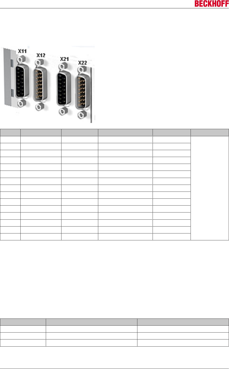
Electrical installation
Servo Drives AX500082 Version: 2.4
9.12.3 X11 and X21: Feedback, high-resolution
The X11 and X21 D-SUB sockets are available for connecting high-resolution feedback systems. In delivery
state X11 is assigned to axis A, X21 to axis B.
Pin EnDAT / BiSS Hiperface Sine / cosine 1 Vpp TTL1) Output current
1 SIN SIN SIN n.c.
max. 250 mA /
channel
2 GND_5 V GND_9 V GND_5 V GND_5 V
3 COS COS COS n.c.
4 Us_5 V n.c. Us_5 V Us_5 V
5 DX+ (Data) DX+ (Data) n.c. B+
6 n.c. Us_9V n.c. n.c.
7 n.c. n.c. REF Z REF Z
8 CLK+ (Clock) n.c. n.c. A+
9 REFSIN REFSIN REFSIN n.c.
10 GND_Sense n.c. GND_Sense GND_Sense
11 REFCOS REFCOS REFCOS n.c.
12 Us_5 V_Sense n.c. Us_5 V_Sense Us_5 V_Sense
13 DX- (Data) DX- (Data) n.c. B -
14 n.c. n.c. Z Z
15 CLK- (Clock) n.c. n.c. A -
1)Attention: Wire break detection is not supported for TTL encoders.
Limit frequency:
1 Vpp = 270 kHz
TTL = 10 MHz
MES = 500 Hz
9.12.4 Resolver
Universal resolvers:
Number of poles Frequency Transmission ratio
2 8 kHz 0.5
6 8 kHz 0.5
8 8 kHz 0.5
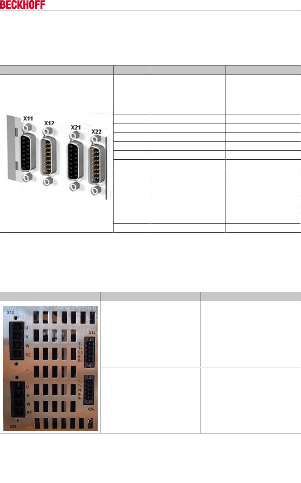
Electrical installation
Servo Drives AX5000 83
Version: 2.4
9.12.5 X12 and X22: Feedback, resolver / Hall
The X12 and X22 D-SUB sockets are available for connecting resolvers or Hall sensors for commutation.
X12 is assigned to axis A in the factory, X22 to axis B.
Pin Resolver Analog Hall sensor
1 Temperature (only PTC,
Klixon or bimetal!).
Switching point: 1300Ω ±
3%
n.c.
2 AGND n.c.
3 COS - (S3) n.c.
4 SIN - (S4) n.c.
5 REF - (R2) n.c.
6 n.c. Sin 1Vpp
7 n.c. -120° or -90° 1Vpp *
8 n.c. Us_9 V (supply)
9 Temp._GND n.c.
10 COS + (S1) n.c.
11 SIN + (S2) n.c.
12 REF + (R1) n.c.
13 n.c. REFSin 1Vpp
14 n.c. -120° or -90° 1Vpp *
15 n.c. GND (supply)
Limit frequency:
Resolver = 300 Hz
9.12.6 X14 and X24: Feedback, OCT (1.5 A - 40 A devices)
Pin OCT / thermal contact
T - OCT -
T+ OCT +
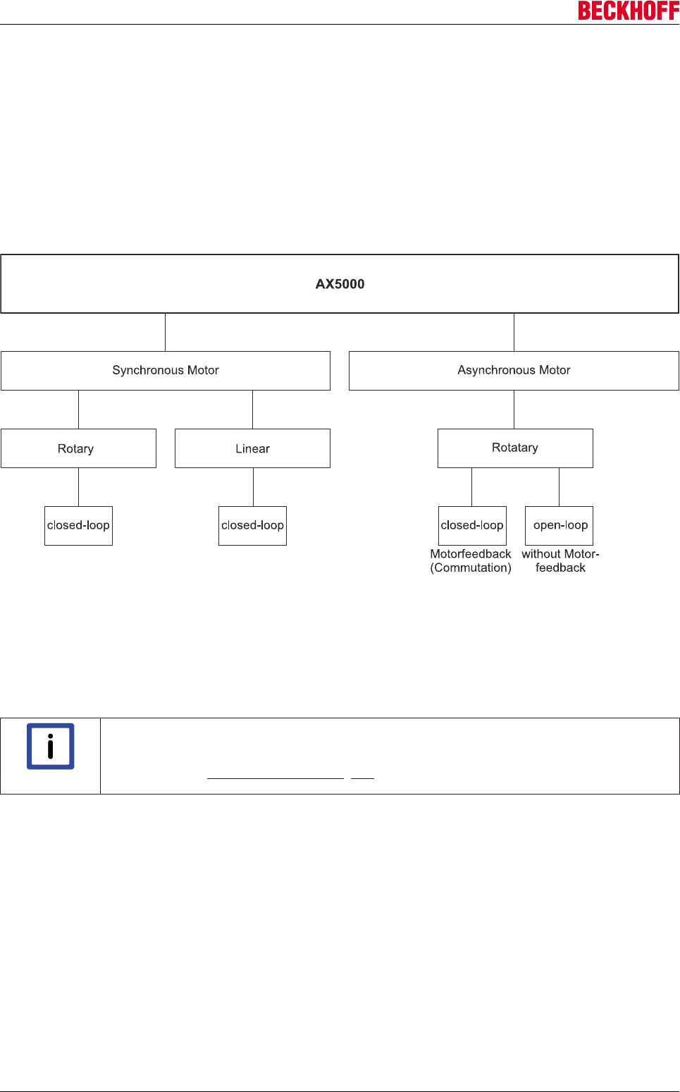
Electrical installation
Servo Drives AX500084 Version: 2.4
9.13 Motors
9.13.1 Concept
Both three-phase synchronous motors and three-phase asynchronous motors can be driven with the servo
drives from the AX5000 series. The operation of asynchronous motors with the AX5000 is useful if, in the
configuration of the drive system, a channel is still freely available and also if asynchronous motors are used
that are to be operated with open-loop control. In the case of the use of asynchronous motors intended for
closed-loop operation, the AX5000 series is a good alternative regardless of the configuration of the drive
system.
9.13.2 Motor data set
A motor dataset contains the motor data and control parameters, which the AX5000 requires for operating
the motor. Beckhoff is continually expanding the pool of available motor data sets and makes the latest
motor database available automatically when the TwinCAT Drive Manager is updated.
Note
Creating motor data sets
Further information on creating motor data sets can be found in
chapter 9.13.4: "Synchronous motors [}86]",
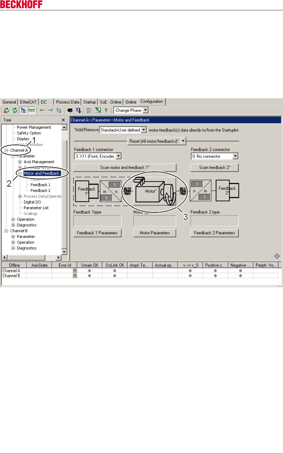
Electrical installation
Servo Drives AX5000 85
Version: 2.4
9.13.3 TwinCAT Drive Manager
Servo drives are parameterized via the TwinCAT Drive Manager (TCDM). The screen masks required for the
parameterization will be explained at this point. If you need basic information about the TCDM, please read
the complete documentation, which is available on our website for download.
Start the TCDM and click the entry (2) under the relevant channel (1) in the tree; the motor/feedback
configuration appears in the TCDM working area. Click on the field (3) in order to open the ‘Motor selection
window’. In the ‘Motor selection window’ you can display all of the available motors, or enter your own
motors including motor parameters (asynchronous motors only).
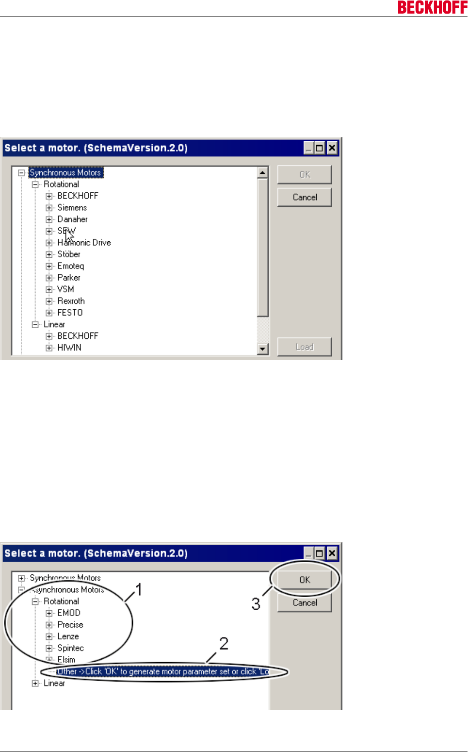
Electrical installation
Servo Drives AX500086 Version: 2.4
9.13.4 Motor types
9.13.4.1 Synchronous motors
In the case of synchronous motors, you can only select an existing motor; it is not possible to register your
own motors. If your motor is not listed, please contact our support department.
9.13.4.2 Asynchronous motors
With the AX5000 you have the possibility to implement a good positioning drive with an inexpensive standard
motor in combination with a low-cost incremental encoder.
Linear
Linear asynchronous motors are not supported at present.
Rotary
1. Motor selection
You can either choose an existing motor (1) or generate parameters for a new motor (2). After selection, click
"OK" (3) to move to the next menu.
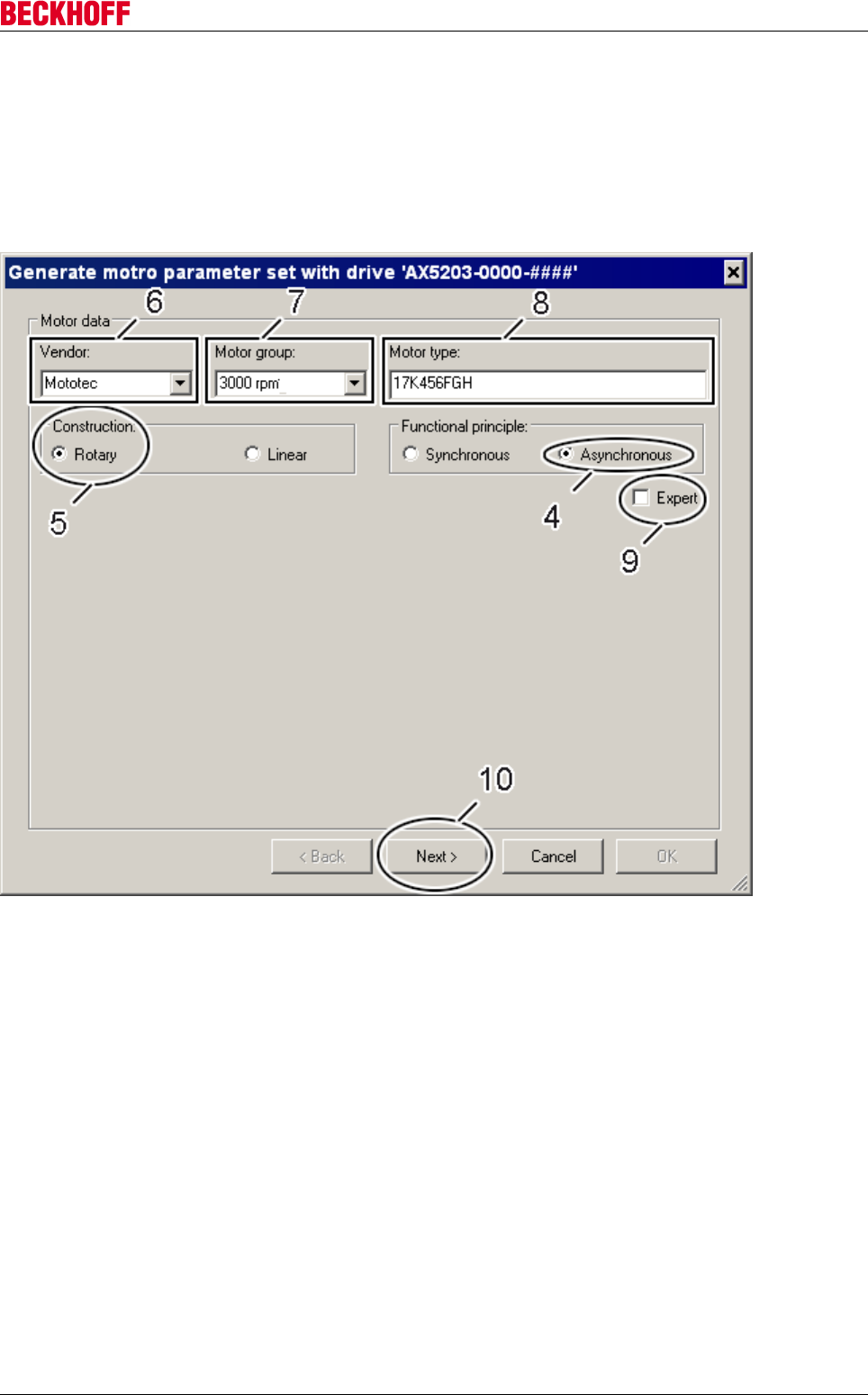
Electrical installation
Servo Drives AX5000 87
Version: 2.4
2. Characteristic motor data
In the next menu characteristic motor data are entered or selected. Expert mode (9) is not currently
supported. Parameters (4) and (5) are preset; you do not need to change them. You can enter a new motor
manufacturer or select an existing motor manufacturer in parameter (6). A new group is generated in
parameter (7) to suit the motor. If you wish to conform to the structure of the motor database, name the
group according to the nominal speed of the motor. Enter the exact type designation of the motor in
parameter (8). Check your entries and then click "Next" (10) to move to the next menu.
Electrical installation
Servo Drives AX500088 Version: 2.4
3. Basic motor data
The basic data are subdivided into three categories: "Basic" (1); "Temperature:" (2) and "Brake" (3).
Basic (1):
Note
It is essential to observe the maximum permitted du / dt of the motor winding!
a) Type of connection: Star or delta connection. If you wire and operate the motor in a star or delta
configuration, please note that the rated motor current changes along with the rated motor voltage and that
the AX5000 can supply a maximum rated voltage of 480 V. Please refer to the motor documentation or name
plate for the permissible motor voltages and currents for star and delta connection.
b) The derating is dependent upon your application. Derating is the difference between the effective rated
channel current and the rated motor current in %. Example: rated motor current = 4 A; effective rated
channel current = 3 A -> derating = 25 %.
c) The ratio of Ip to In (overload factor) is set to 1.5 as standard and must be checked against the motor
documentation or name plate.
d) The rated current must be adjusted in accordance with the type of connection and checked against the
motor documentation or name plate.
e) The maximum motor speed is dependent upon the mechanical properties and the maximum rotary field
frequency of the AX5000. Please observe the M / f curve and the field weakening according to the motor
documentation.
f) The rated voltage must be adjusted in accordance with the type of connection and checked against the
motor documentation or name plate.
g) The nominal speed is dependent upon the number of pole pairs and the nominal frequency and must be
checked against the motor documentation or name plate.
h) The nominal frequency is set to 50 Hz as standard and must be checked against the motor documentation
or name plate.
i) The power factor (cos phi) is set to 0.8 as standard and must be checked against the motor documentation
or name plate.
Temperature (2):
k) The type of motor temperature monitoring used and the AX5000 input used must be selected.
Note
For further information on the combinations you intend to use please contact
the Beckhoff applications department.
m) The temperature at which a warning is given is set to 80 °C. This parameter is effective only for KTY
sensors.
n) The temperature at which the motor is switched off is set to 140 °C and must be checked against the
motor documentation or name plate. This parameter is effective only for KTY sensors.
Brake (3):
o) The type of motor brake used must be selected and checked against the motor documentation or name
plate.
Double-check all entries and click ‘Next’ (4) to move to the next menu.
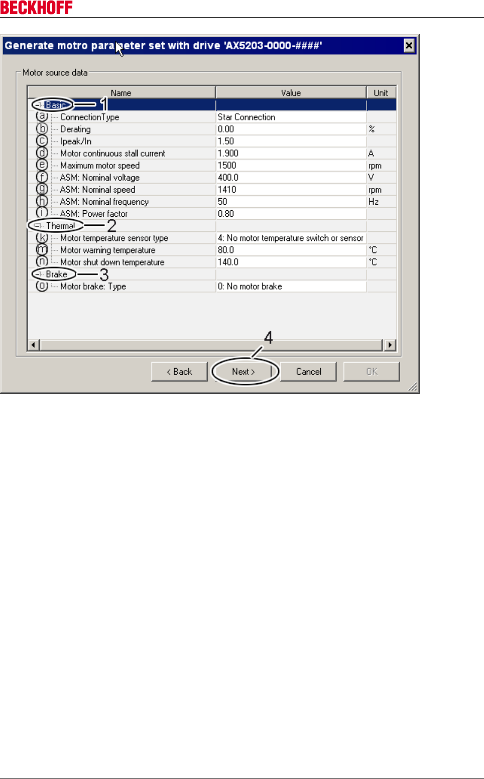
Electrical installation
Servo Drives AX5000 89
Version: 2.4
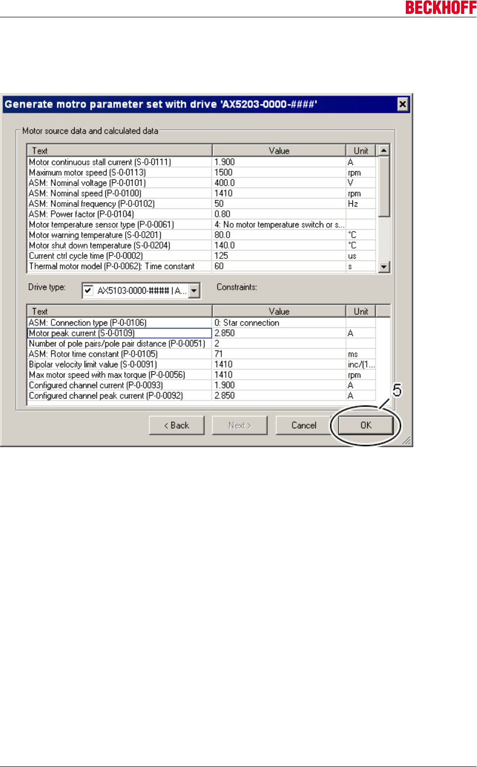
Electrical installation
Servo Drives AX500090 Version: 2.4
4. Summary
The motor data entered and the data calculated from them are displayed in this window. Please check ALL
parameters once more for plausibility and click ‘OK’ (5) to move to the next menu.
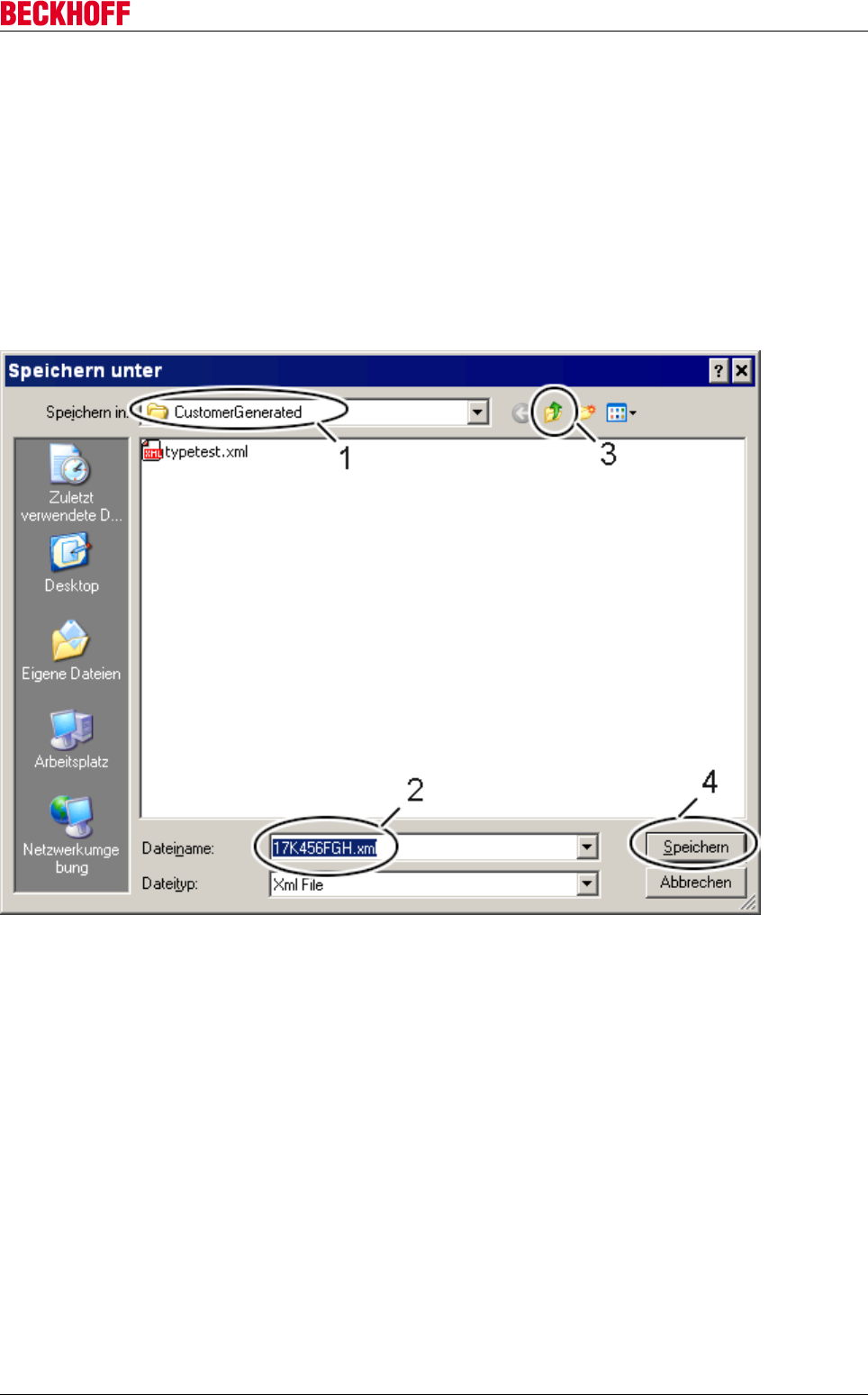
Electrical installation
Servo Drives AX5000 91
Version: 2.4
5a. Default storage folder for self-generated motor data sets
The default storage folder for user-generated motor datasets is called "CustomerGenerated" (1), and the
suggested file name (2) corresponds to the motor type entered above (see "Characteristic motor data"). This
storage folder has the advantage that you can find your self-generated motor data sets at a glance; however,
they are not included in the above list above under 1. ‘Motor selection’, but are only visible if you click the
‘Load’ button at the bottom right under 1. ‘Motor selection’. The suggested name designates only the XML
file of the motor data set. For the purposes of displaying in the lists, the XML file is read and the
corresponding identifying motor data (‘Vendor’, ‘Motor group’ and ‘Motor type’) are listed as a selection.
To save your data, click on "Save" (4), which then takes you to the last menu.
If your self-generated motor data sets are to be listed directly in the above list under 1. ‘Motor selection’, click
on the symbol (3) to open the "MotorPool" folder.
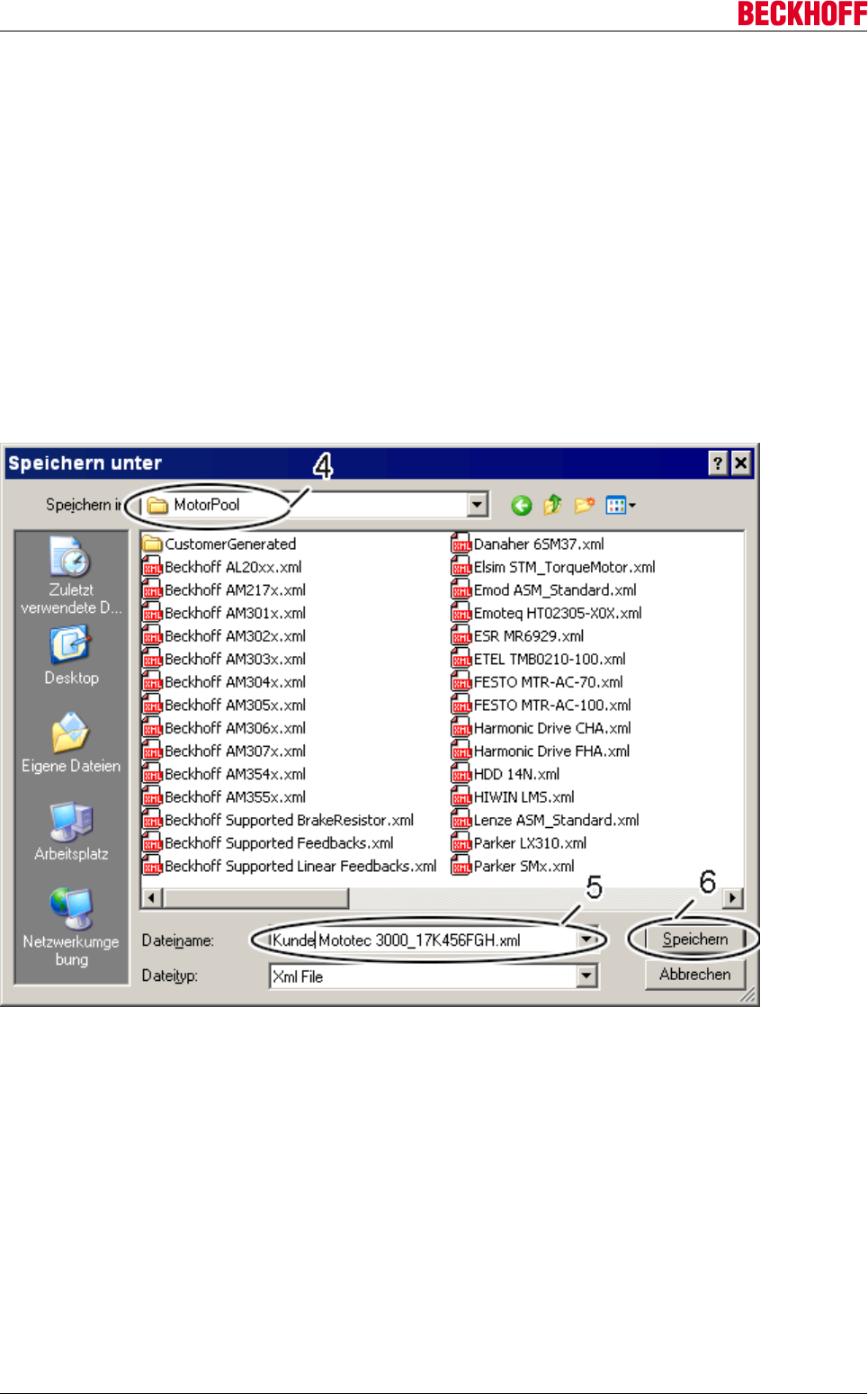
Electrical installation
Servo Drives AX500092 Version: 2.4
5b. Default storage folder for the motor data sets from the Beckhoff motor database
The default storage folder for the motor data sets provided is called "MotorPool" (4). All motor data sets from
the Beckhoff motor database are saved here in the form of XML files. We recommend that you assign a
unique file name to your self-generated motor data set, so that you can identify it (5):
Customer = name of your company
Mototec = The name (Vendor) assigned by you under 2. "Identifying motor data"
3000 = The motor group assigned by you under 2. "Identifying motor data"
17K456FGH = The motor type assigned by you under 2. "Identifying motor data"
Of course, you can also assign an arbitrary file name. The assigned name designates only the XML file of
the motor data set. For the purposes of displaying in the lists, the XML file is read and the corresponding
identifying motor data (‘Vendor’, ‘Motor group’ and ‘Motor type’) are listed as a selection.
You create one XML file for each motor data set; the motors from the same motor group of a manufacturer
(Vendor) are always summarized in the XML files for Beckhoff motor data sets.
To save your data, click on "Save" (6), which then takes you to the previous menu.
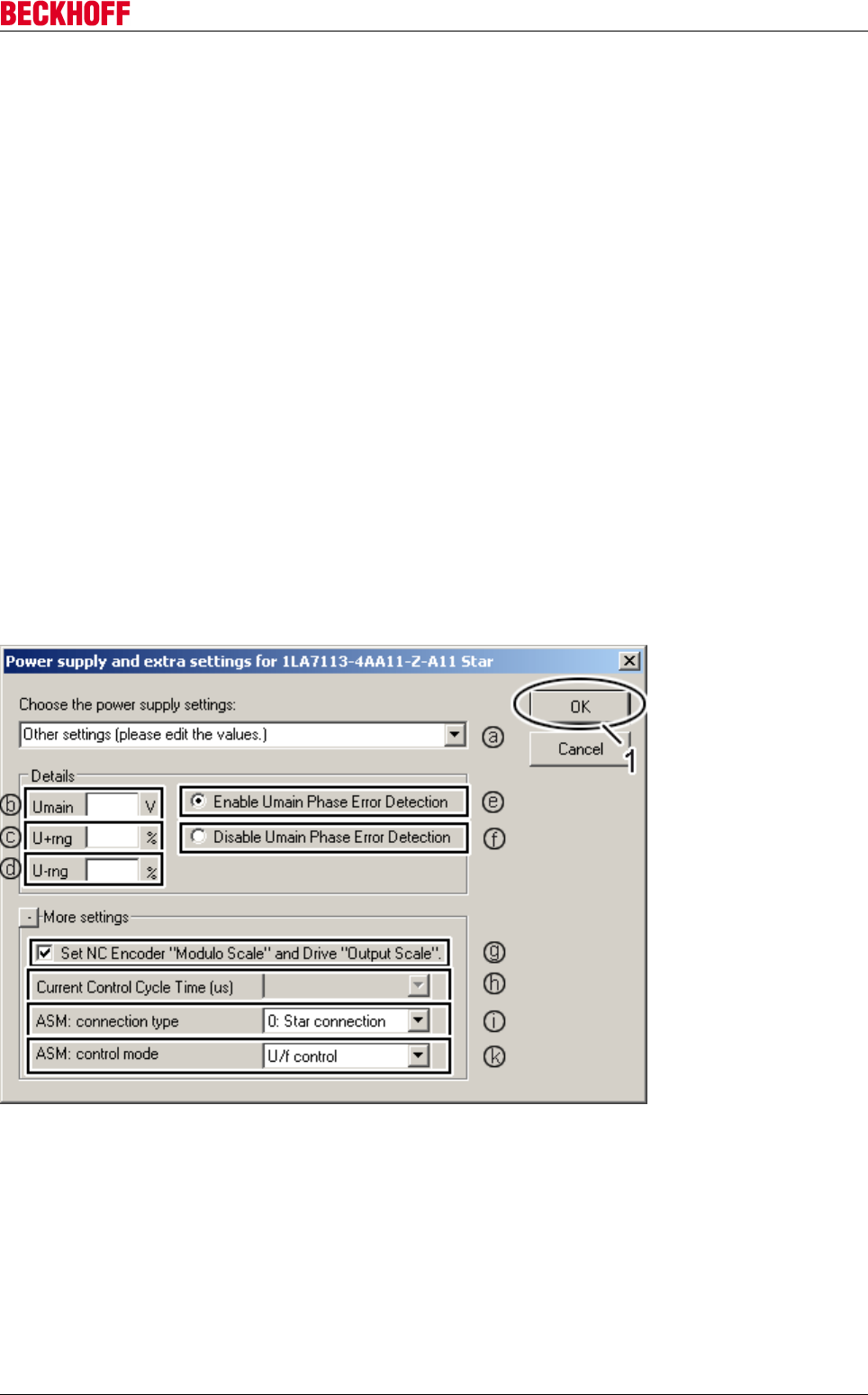
Electrical installation
Servo Drives AX5000 93
Version: 2.4
6. Mains voltage and further settings
This window also appears when you select an existing motor data set (synchronous motor or asynchronous
motor). You can adapt the following entries at any time.
a) You can select one of the pre-defined mains voltage variants or you can specify one of your own.
b) Enter the mains voltage (only possible if no mains variant was selected under a)).
c) Enter the upper tolerance of the mains voltage (only possible if no voltage was selected in a)).
d) Enter the lower tolerance of the mains voltage (only possible if no voltage was selected in a)).
e) + f) Phase monitoring is only useful for a 3-phase mains supply. Switch phase monitoring on or off (only
possible if no voltage was selected in a)).
g) Use this setting to enable automatic transfer of the resolution of the encoder and the scaling factor from
the AX5000 to the NC. (Only required if the motor was integrated via an NC axis).
h) The cycle time of the current controller is 125 μs.
i) Selection of the type of ASM connection. If you have generated the motor data set, you can only select the
type of connection entered under 3. "Basic motor data –a)". If Beckhoff has generated the motor data set,
you can choose between star connection and delta connection.
k) Selection of the ASM control mode. If you select "U/f control", only open-loop operation of the motor is
possible; the AX5000 then acts like a servo drive. If you select "i-control with feedback", closed-loop
operation of the motor is possible, but the motor must be equipped with a feedback system. Click on "OK" (1)
to complete the procedure.
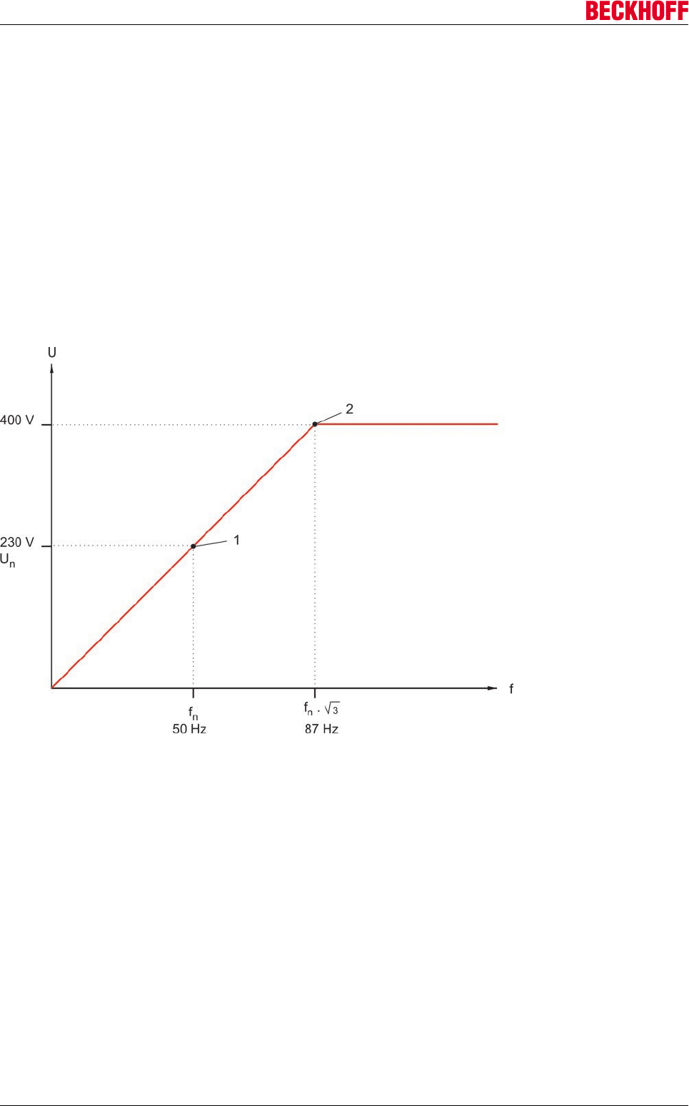
Electrical installation
Servo Drives AX500094 Version: 2.4
Open-loop
If open-loop operation of the motor is desired, you can influence the operating behavior with the following
parameters.
Interdependence between the type of connection of the motor, the speed and the rated output
current of the AX5000
Example motor:
Asynchronous motor with rated voltage 230 V and rated current 6 A at 50 Hz for delta connection or rated
voltage 400 V, rated current 3.5 A at 50 Hz for star connection
If your application requires speeds above the nominal speed (1), this requirement can be realized without
having to use a bigger motor:
The AX5000 can provide 400 V of channel output voltage and thus operate the asynchronous motor in delta
connection at up to 87 Hz (2) without field weakening occurring, i.e. with the rated torque. You only need to
note that a rated current of 6 A is required.
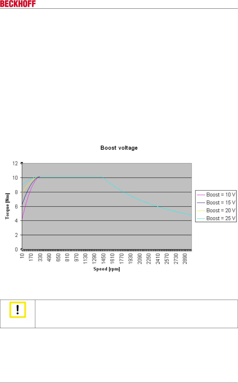
Electrical installation
Servo Drives AX5000 95
Version: 2.4
Boost voltage
The operation of an asynchronous motor with a linear U/f characteristic curve results in a weakening of the
torque in the lower speed range due to the dominant resistive component. The standstill torque is zero
without a boost voltage. Furthermore, the asynchronous motor requires a certain time after the current is
applied in order to build up the magnetic field on the rotor and, hence, to generate the magnetic force or the
torque. If your application can not tolerate this delay, there is a possibility to reduce this time delay via the
so-called "boost voltage", which "premagnetises" the rotor. With "premagnetization" a magnetic field is
created in the rotor even though the rotor is not moving. Torque is hence immediately available to rotate the
rotor shaft if a target speed is specified. The interdependence between the boost voltage, speed and torque
is illustrated in the graphic below on the basis of an example motor. The influence of the boost voltage on to
the torque is clearly visible at low speeds.
Example motor:
Rated speed: 1410 rpm
Rated torque: 10.2 Nm
Breakdown torque: 28.6 Nm
Starting torque: 25.5 Nm
Power factor: 0.78
Efficiency: 0.79
The boost voltage is parameterized in the IDN-P-0-0103. Most applications will be covered by the default
setting of 10 V.
Attention
Attention: destruction of the motor
In an asynchronous motor without an external fan, the motor temperature must be moni-
tored in the lower speed range when boost voltage is used. If necessary, you can change
the boost voltage online.
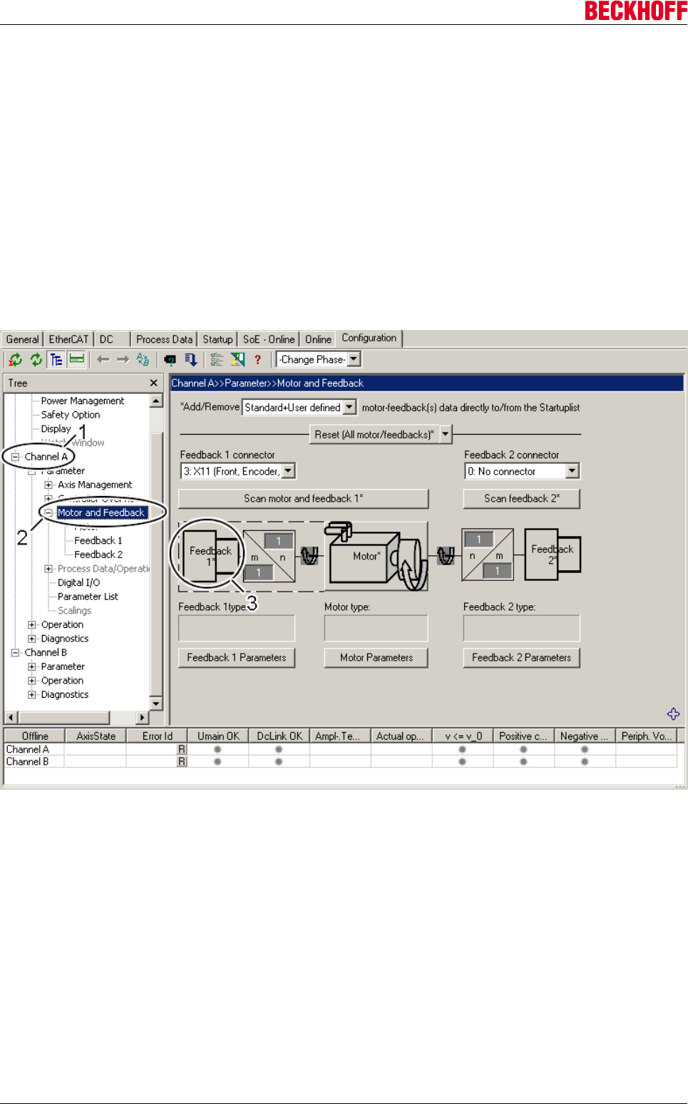
Electrical installation
Servo Drives AX500096 Version: 2.4
Settings for ramping up and down
In the open-loop operation of the asynchronous motor, the values you need to adjust for the ramps depend
on the application.
The ramp-up is parameterized in the IDN S-0-0136 and the ramp-down in the IDN S-0-0137.
Closed-loop
If closed-loop operation of the asynchronous motor is desired, you must select the feedback system used in
the motor in the TCDM.
Feedback
Start the TCDM and click the entry (2) under the relevant channel (1) in the tree; the motor/feedback
configuration appears in the TCDM working area. Click on the ‘Feedback 1’ (3) field to open the ‘Feedback
selection window’. You can view all available feedback systems in the ‘Feedback selection window’.
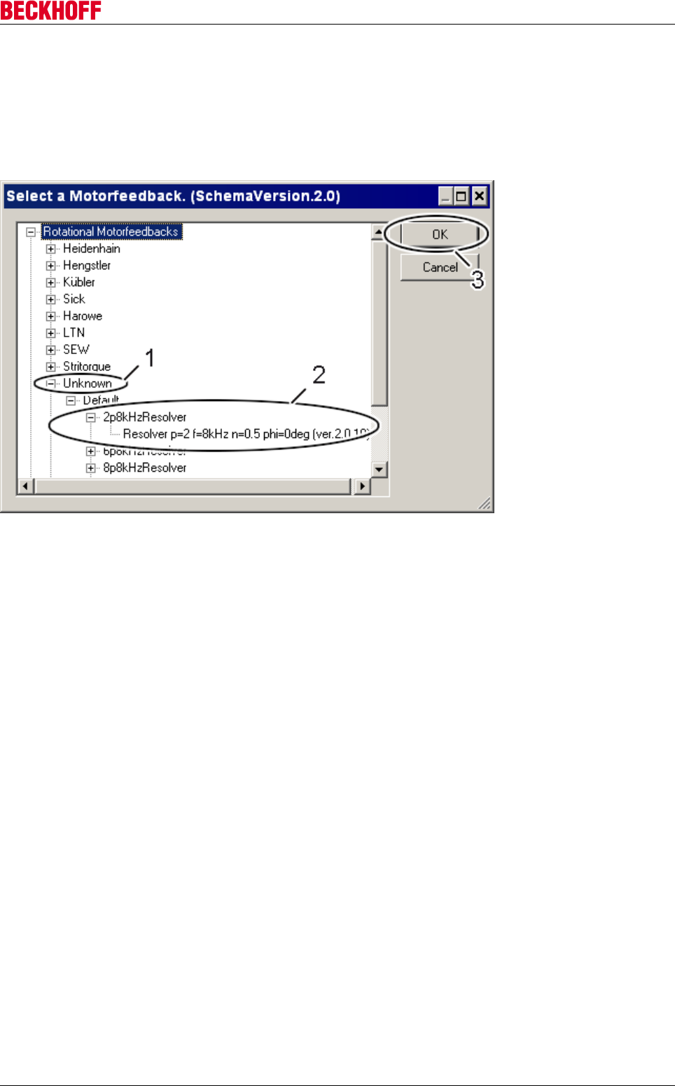
Electrical installation
Servo Drives AX5000 97
Version: 2.4
1a. Feedback selection - resolver
Only one of the listed feedback systems can be selected. Either choose the feedback system of an existing
manufacturer or choose a standard feedback system under "Unknown" (1). If your motor is equipped with a
resolver, determine the generic parameters of the resolver and select the appropriate resolver type (2).
Typical generic parameters for the classification of resolvers are the number of poles "p" and the gear ratio
"n". Click on "OK" (3) to complete the procedure.
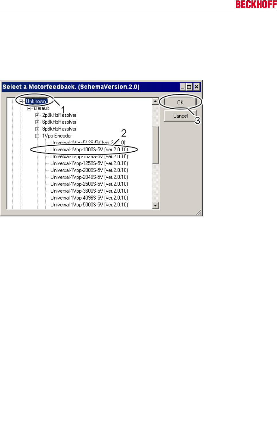
Electrical installation
Servo Drives AX500098 Version: 2.4
1b. Feedback selection - 1Vpp encoder
You can only select one existing feedback system. Either choose the feedback system of an existing
manufacturer or choose a standard feedback system under "Unknown" (1). If your motor is equipped with a
1Vpp encoder, determine the parameters of the feedback system and select the appropriate encoder (2).
Typical parameters for the classification of 1Vpp encoders are the number of lines ‘s’ and the supply voltage
‘5V or 5V fixed’. The difference between the two voltage variants is the use of a sense line (5V). Click on
"OK" (3) to complete the procedure.
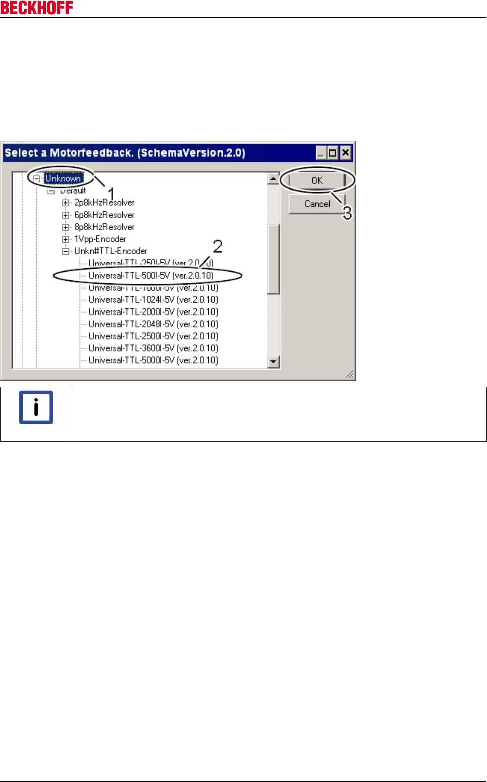
Electrical installation
Servo Drives AX5000 99
Version: 2.4
1c. Feedback selection - TTL encoder
You can only select one existing feedback system. Either choose the feedback system of an existing
manufacturer or choose a standard feedback system under "Unknown" (1). If your motor is equipped with a
TTL encoder, determine the parameters of the feedback system and select the appropriate TTL encoder (2).
Typical parameters for the classification of TTL encoders are the number of lines ‘s’ and the supply voltage
‘5V or 5V fixed’. The difference between the two voltage variants is the use of a sense line (5V). Click on
"OK" (3) to complete the procedure.
Note
TTL Encoder!
Wire break detection is not supported for TTL encoders.
Commutation
In asynchronous motors the rotor magnetic field is generated electrically by means of rotor windings, which
are energized by the servo drive. For this reason, neither a part-absolute nor an absolute encoder system is
required for commutation; wake+shake also does not need to be used. The magnetic field of the stator
induces a voltage in the rotor windings. This leads to a current flow in the rotor windings. This in turn
generates a magnetic field, which produces a torque.
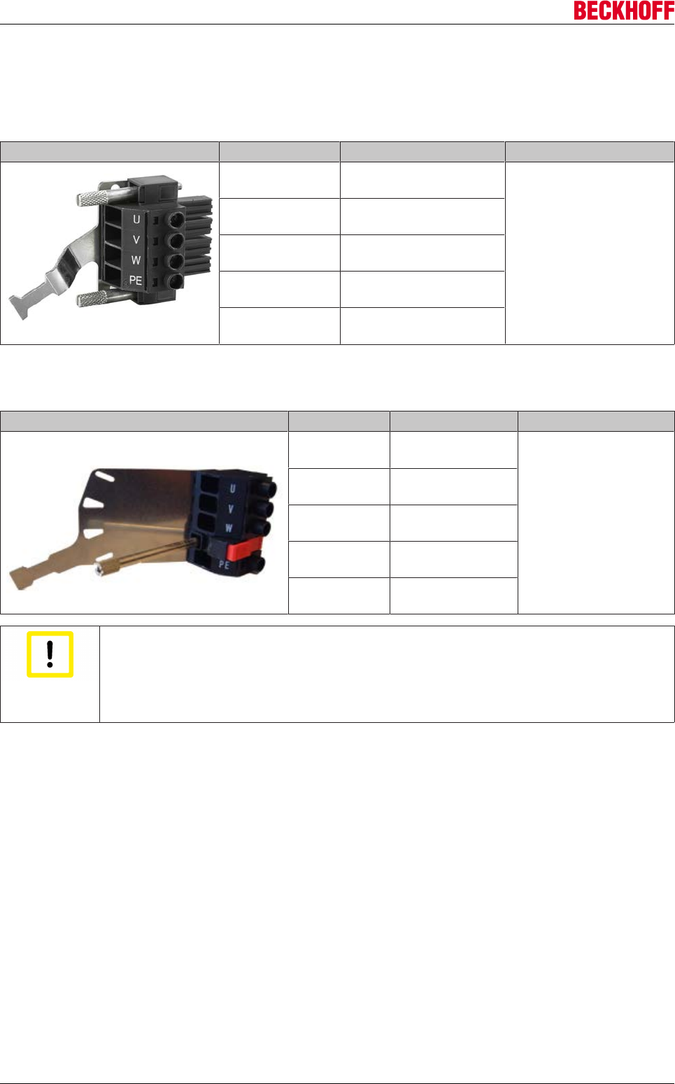
Electrical installation
Servo Drives AX5000100 Version: 2.4
9.13.5 Motor connections (1.5 A - 40 A devices)
9.13.5.1 X13 (A), X23 (B): AX5101 - AX5125 and AX520x
Terminal point Signal Tightening torque
U Motor connection U
0.6 Nm
V Motor connection V
W Motor connection W
PE Protective conductor
Shroud Shield
9.13.5.2 X13: AX5140
Terminal point Signal Tightening torque
U Motor connection U
1.0 Nm
V Motor connection V
W Motor connection
W
PE Protective
conductor
Shroud Shield
Attention
Shield connection!
The shield connection is established via the shroud of the motor connector. Please tighten
the knurled screw with a screwdriver (max. 1.0 Nm). Inadequately shield connection as a
result of a loose plug can lead to uncontrolled interference currents, which may also flow
via encoder or resolver cables. This approach can thus result in feedback problems.
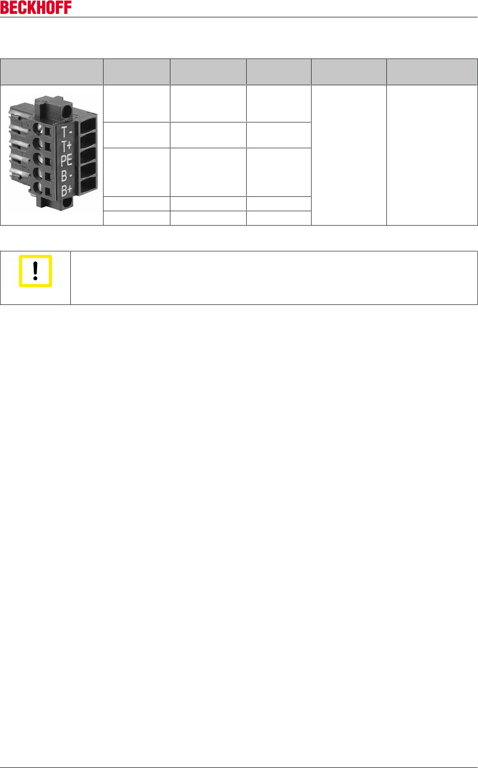
Electrical installation
Servo Drives AX5000 101
Version: 2.4
9.13.5.3 X14 (A), X24 (B): Motor brake, thermal contact (1.5 A - 40 A devices)
Terminal
point
Signal Current
load
Tightening
torque
Conductor cross-
section
T - OCT and temp.
- *
max. 0.25 Nm 0.2 – 1.5 mm²
T+ OCT + and
temp. + *
PE Protective
conductors and
inner shields of
the signal pairs
B - Brake, GND
B+ Brake (Up) + max. 2.2 A
*) switch, KTY 83-1xx or KTY 84-1xx
Attention
Destruction of the AX5000!
Read the "Cables" chapter carefully and be sure to adhere to the specifications contained
in it.
Temperature monitoring for Beckhoff motors
AM2000 with resolver
Via resolver cable.
AM2000 with EnDat
The thermal protection contact is implemented in the encoder cable to the AX5000 and must be bridged to
the resolver connection via an adapter / Y cable.
AM2000 with BiSS
Not available.
AM3000 with resolver
Via resolver cable.
AM3000 with EnDat
Via motor cable.
AM3000 with BiSS
Via motor cable.
Linear motors AL2000
The thermal protection contact exits the motor via a separate cable.
1. If the pre-assembled Beckhoff motor and encoder cable is used, an additional thermal protection con-
tact cable (ZK4540-0020-xxx) is required for connecting the thermal protection contact with the
AX5000 resolver interface, where temperature evaluation takes place.
2. If the AL2250 connector box is used, the thermal protection contact is automatically bridged to the mo-
tor cable.
Temperature monitoring and evaluation for motors from other manufacturers
1. Temperature monitoring via PTC, Klixon or bimetal
Evaluation either on the resolver interface (X12 / X22) or the temperature contact (X14 / X24)
2. Analog temperature evaluation (e.g. KTY)
Evaluation only on the temperature contact (X14 / X24)
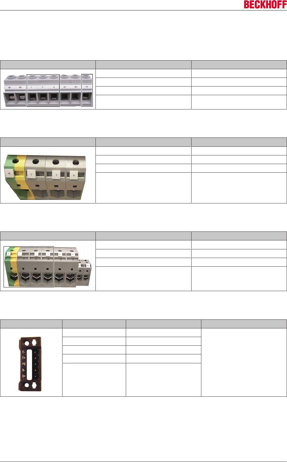
Electrical installation
Servo Drives AX5000102 Version: 2.4
9.13.6 Motor connections (60 A - 170 A devices)
9.13.6.1 X13: AX5160 and AX5172
Terminal point Connection
U Motor connection U
V Motor connection V
W Motor connection W
PE Protective conductor
9.13.6.2 X13: AX5190 and AX5191
Terminal point Connection
U Motor connection U
V Motor connection V
W Motor connection W
PE Protective conductor
9.13.6.3 X13: AX5192 and AX5193
Terminal point Connection
U Motor connection U
V Motor connection V
W Motor connection W
PE Protective conductor
9.13.6.4 X14: Motor brake, thermal contact
Terminal point Connection Output current
T - Temp. - *
max. 2.2 A
T+ Temp. + *
PE Signal pair shield
B - Brake GND
B+ Brake (Up) +
*) switch, KTY 83-1xx or KTY 84-1xx
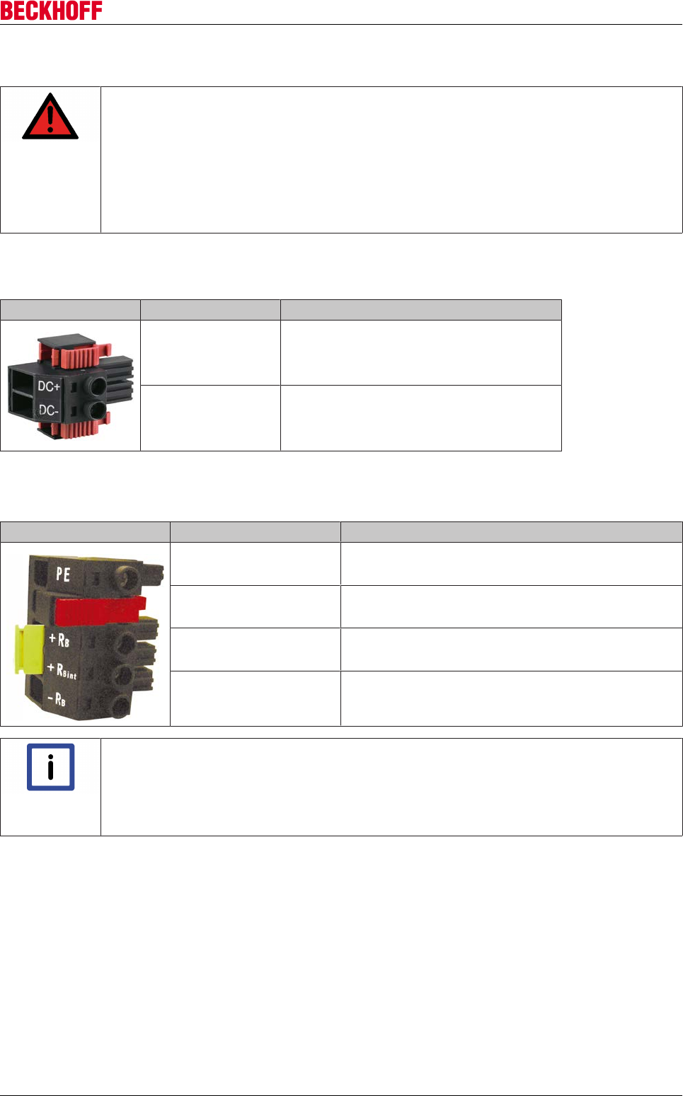
Electrical installation
Servo Drives AX5000 103
Version: 2.4
9.14 External brake resistor
DANGER
High voltage – Danger of death!
Due to the DC link capacitors, the DC link terminal points "ZK+ and ZK- (DC+ and DC-)"
and "RB+ and RB-" may be subject to dangerous voltages of up to 875 VDC, even after the
servo drive was disconnected from the mains supply.
Wait 5 minutes for the AX5101 - AX5125 and AX520x; 15 minutes for the AX5140/AX5160/
AX5172; 30 minutes for the AX5190/AX5191; 45 minutes for the AX5192/AX5193 after dis-
connecting, and measure the voltage at the DC link terminal points "ZK+ and ZK- (DC+ and
DC-)". The device is safe once the voltage has fallen below 50 V.
9.14.1 X02 - AX5101-AX5125 and AX520x
Terminal point Signal
DC+ DC link +
DC- DC link -
9.14.2 X07 - AX5140
Terminal point Signal
PE Protective conductor
+RBExternal brake resistor +
+RBint Internal brake resistor +
-RBBrake resistor GND
Note
Operation of AX5140
Commissioning the AX5140 can only be carried out when the terminal points "+RBint" and
"+RB" are bypassed (delivery state) or an external brake resistor is connected (terminal
points +RB" and "-RB"). If these measures are not taken then the AX5140 will be stopped
with the error message "FD4B – undervoltage".
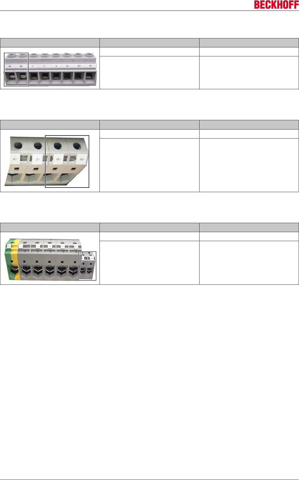
Electrical installation
Servo Drives AX5000104 Version: 2.4
9.14.3 AX5160 and AX5172
Terminal point Connection
RB + Ext. brake resistor +
RB - Ext. brake resistor -
9.14.4 AX5190 and AX5191
Terminal point Connection
RB + Ext. brake resistor +
RB - Ext. brake resistor -
9.14.5 AX5192 and AX5193
Terminal point Connection
RB + Ext. brake resistor +
RB - Ext. brake resistor -
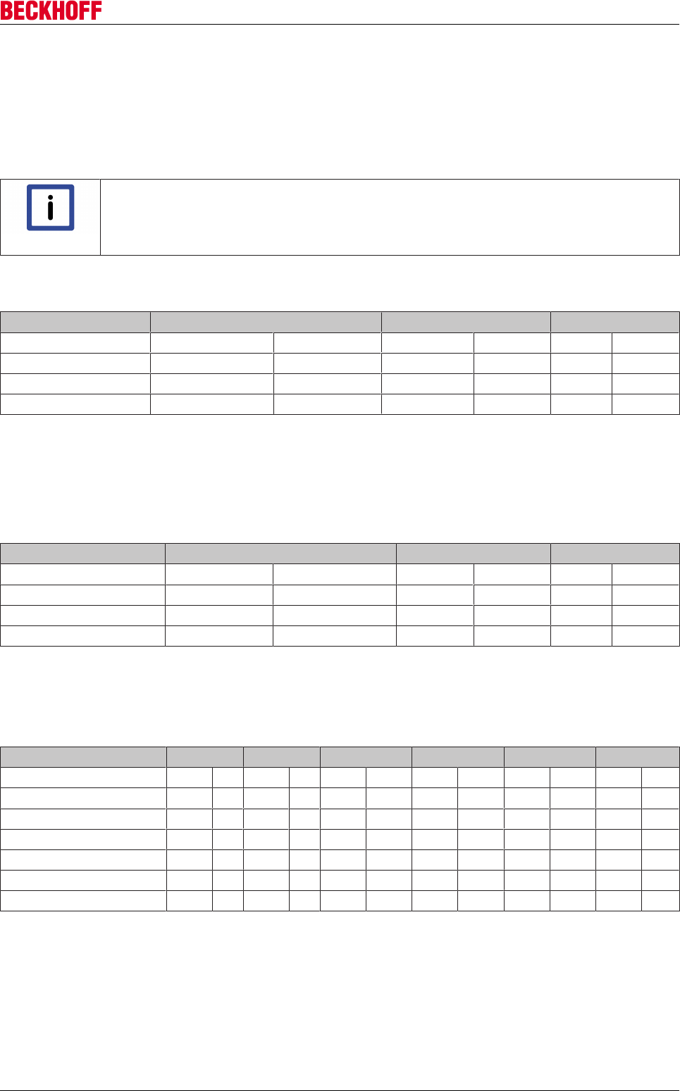
Electrical installation
Servo Drives AX5000 105
Version: 2.4
9.15 Motors and cables for servo drives
With longer motor cables the resulting commutation currents can lead to EMC faults. Use the tables below to
check whether mains chokes or mains filters have to be used in your application. When selecting the control
cabinet ensure that there is adequate space for mains chokes and mains filters, etc.
Lay the power and signal cables in separate metal cable ducts or, if both types of cable use the same metal
cable duct, make sure there is an earthed metal dividing wall between the cables.
Note
Motor chokes
For the AX5160 to AX5193 series no motor chokes are required.
Maximum cable length (including extensions) for a rated motor voltage up to 400 V:
Motor choke AX5101-AX5112 a. AX52xx AX5118 a. AX5125 AX5140
C21) C3 C22) C3 C2 C3
Without < 25 m < 25 m < 25 m < 25 m - < 35 m
AX2090-MD50-0012 < 100 m < 100 m - - - -
AX2090-MD50-0025 - - < 50 m < 50 m - -
1) For compliance with EN 61800-3 only with mains filter AX2090-NF50-0014.
2) For compliance with EN 61800-3 only with mains filter AX2090-NF50-0032.
In exceptional cases (sensitive sensors, etc.) it can be necessary to use a motor choke even for motor cable
lengths < 25 m.
Maximum cable length (including extensions) for a rated motor voltage up to 480 V
Motor choke AX5101-AX5112 a. AX52xx AX5118 a. AX5125 AX5140
C21) C3 C22) C3 C2 C3
Without < 20 m < 20 m < 20 m < 20 m - < 35 m
AX2090-MD50-0012 < 100 m < 100 m - - - -
AX2090-MD50-0025 - - < 50 m < 50 m - -
1) For compliance with EN 61800-3 only with mains filter AX2090-NF50-0014.
2) For compliance with EN 61800-3 only with mains filter AX2090-NF50-0032.
In exceptional cases (sensitive sensors, etc.) it can be necessary to use a motor choke even for motor cable
lengths < 20 m.
Mains choke AX5160 AX5172 AX51901) AX51912) AX51922) AX51933)
C2 C3 C2 C3 C2 C3 C2 C3 C2 C3 C2 C3
AX2090-ND50-0060 4) 5) - - - - - - - - - -
AX2090-ND50-0072 - 4) 5) --------
AX2090-ND50-0090 - - - - 10 m 25 m - - - - - -
AX2090-ND50-0110 - - - - - - 10 m 25 m - - - -
AX2090-ND50-0143 - - - - - - - - 10 m 25 m - -
AX2090-ND50-0170 - - - - - - - - - - 10 m 25 m
1) For compliance with EN 61800-3 only with mains filter AX2090-NF50-0100.
2) For compliance with EN 61800-3 only with mains filter AX2090-NF50-0150.
3) For compliance with EN 61800-3 only with mains filter AX2090-NF50-0180.
4)Without mains choke up to 10 m max.
5)Without mains choke up to 25 m max.
Advanced system characteristics
Servo Drives AX5000106 Version: 2.4
10 Advanced system characteristics
10.1 Commissioning
10.1.1 Important information for commissioning
WARNING
Caution - Risk of injury!
Electronic equipment is not fail-safe. The machine manufacturer is responsible for ensuring
that the connected motors and the machine are brought into a safe state in the event of a
fault in the drive system.
Please be aware each time before commissioning the AX5000 that connected motors can make uncontrolled
movements, which cannot always be prevented even by the AX5000’s integrated diagnostic system, or may
permit uncontrolled movements until the diagnostic system responds. Analyze your system and take suitable
precautions to prevent damage being caused by these uncontrolled movements.
Potential causes of uncontrolled movements:
The diagnostic system of the AX5000 is equipped with complex plausibility checks, which constantly monitor
installation, operation, parameterization and operation and, if necessary, interrupt them with a diagnostic
message. The parameters listed below are monitored by default, although it is not possible to cover all
eventualities.
• Incorrect commutation results (e.g. on wake & shake), please note chapter Commutation techniques-->
Commutation error "F2A0".
• Take special care with third-party motors: When a motor or encoder is replaced or when a different
SysMan file (.TSM) is used, always execute the command "P-0-0166" without load connection and
analyze the result. If necessary, adjust the commutation offset, as described in the chapter on the
commutation process.
• Input of invalid parameters
• Measuring transducer and/or signal transducer defective or incorrectly adjusted
• Cables defective or not adequately shielded
• Incorrectly attached sensors
CAUTION
Increased attention in the case of vertical axes!
When commissioning vertical axes, the risk consideration described above is to be carried
out with particular care. An uncontrolled movement can mean the sudden falling down of a
load in this case.
10.1.2 Software requirements
Generally, two TwinCAT software modules are required for controlling the AX5000:
• TwinCAT NC PTP
• TwinCAT PLC
TwinCAT NC is a closed software module whose features the user can only influence via parameters. The
TwinCAT NC parameters can be set in the TwinCAT System Manager.
TwinCAT PLC is a program code which the user creates in the PLC Control development environment.
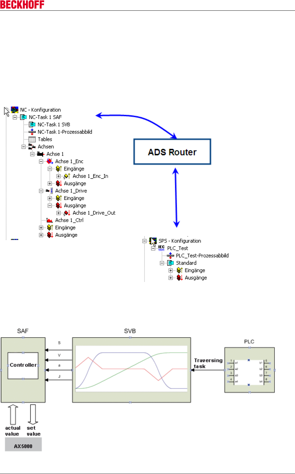
Advanced system characteristics
Servo Drives AX5000 107
Version: 2.4
Structure of TwinCAT NC PTP
TwinCAT NC has 2 tasks:
• NC task 1 SPP (Set PreParation task)
• NC task 1 SEC (Set ExeCution task)
The SPP task is responsible for planning the requested traversing task. The SAF task is responsible for
executing the motion command.
The traversing task leaves the PLC in the direction of the ADS router with destination NC-Task 1 SVB (NC
task 1 SPP). The router relays the telegram to this task.
The NC accepts or rejects the message. The response arrives back at the calling block in the PLC via the
same route. Instructions are issued based on blocks contained in TCMC.lib. Once the NC has accepted the
instruction, the system tries to calculate a solution taking into account the boundary conditions (max.
velocity, acceleration, deceleration, and jerk).
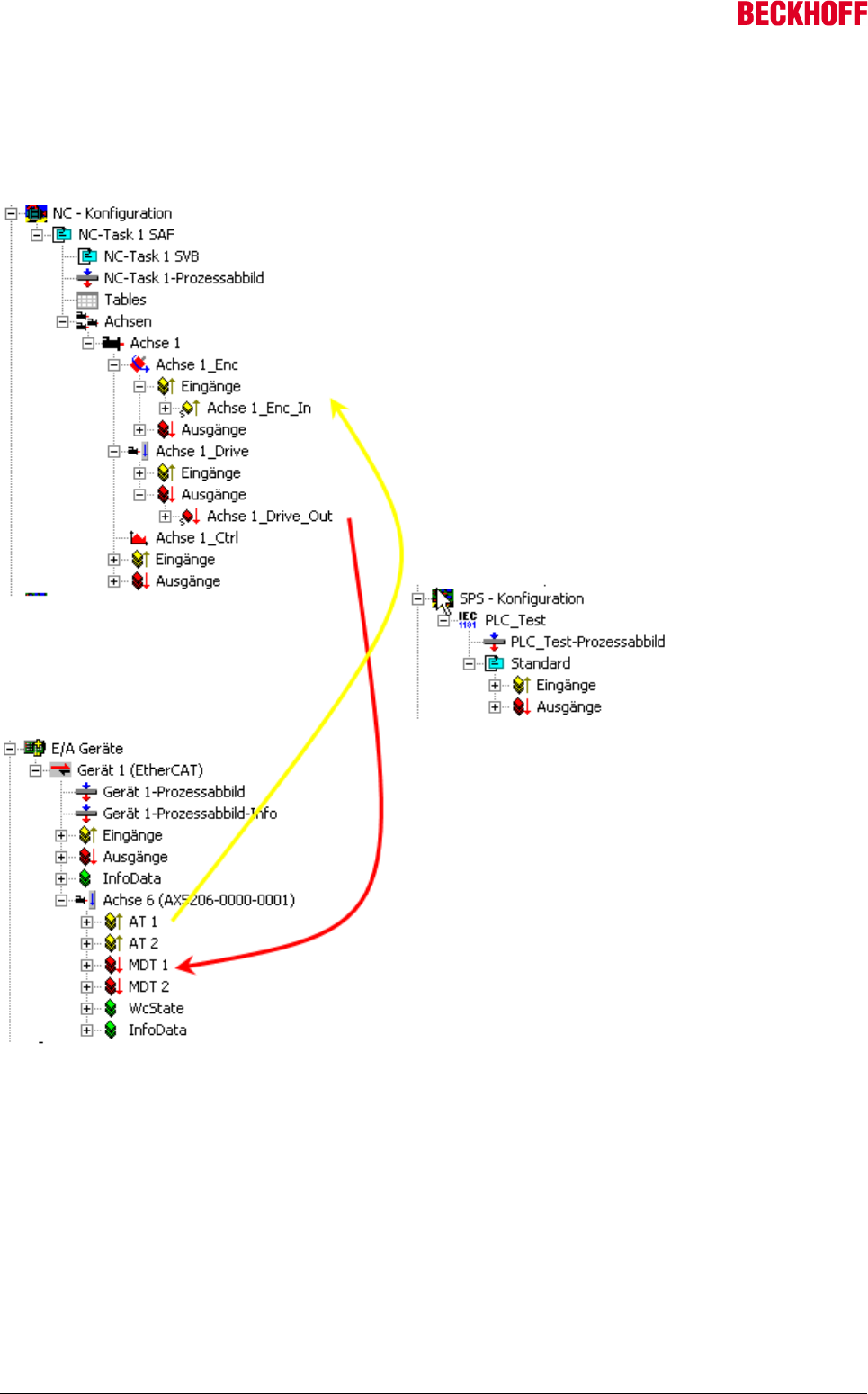
Advanced system characteristics
Servo Drives AX5000108 Version: 2.4
If a solution exists, a table containing the position (s) velocity (v), acceleration/deceleration (a) and jerk (j) for
the whole travel time within the sampling time of the SEC task is transferred to the SEC.
If no solution exists, the system deviates downwards based on maximum jerk, maximum acceleration, and
maximum velocity (in this order).
Actual and set values shown in the diagram are served by the 1_Enc axis and 1_Drive axis components.
Since the AX5000 is known to the system as a slave, linking can take place automatically if required. In the
event of problems the link can be checked by the user.
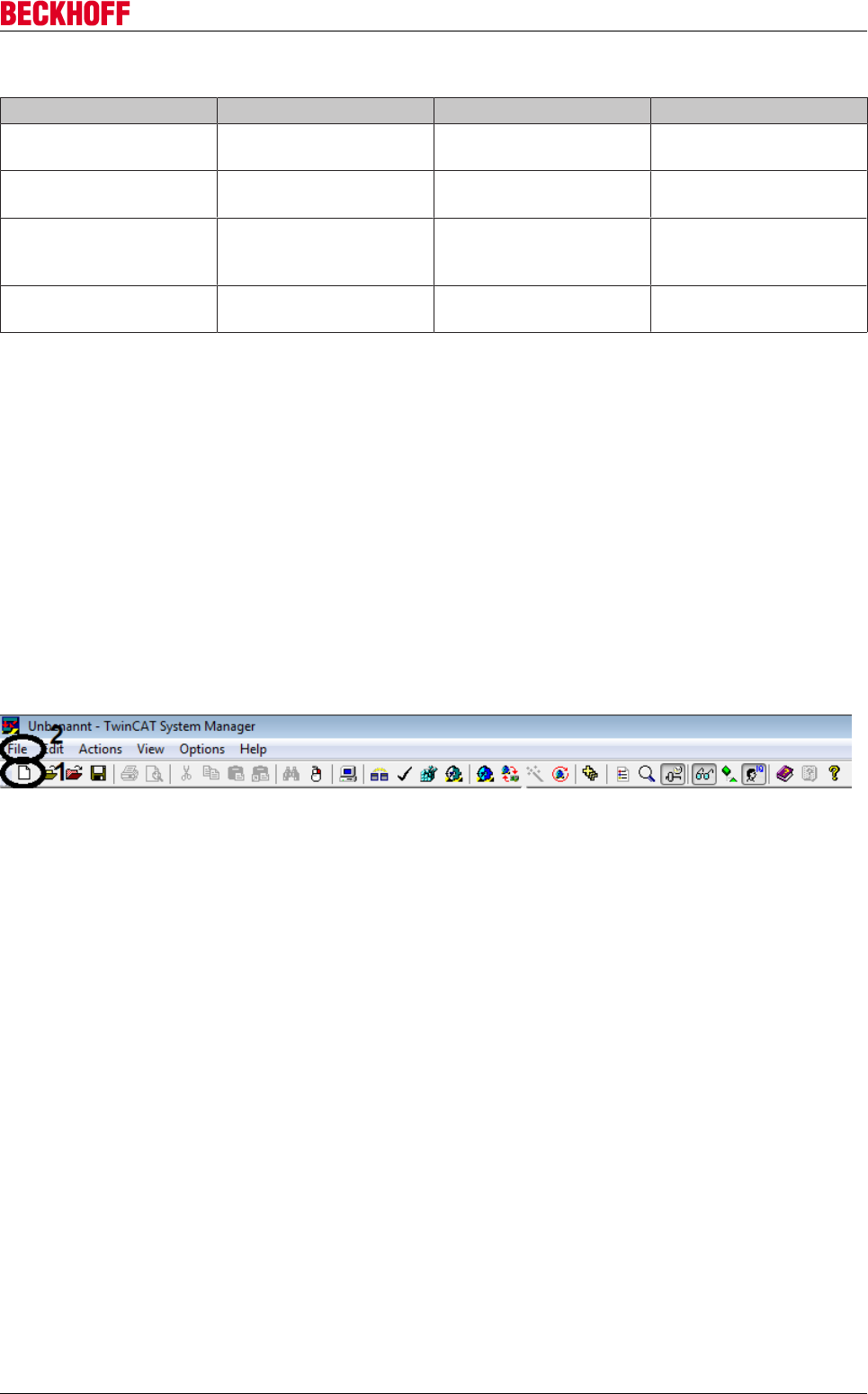
Advanced system characteristics
Servo Drives AX5000 109
Version: 2.4
NC / AX5000 link specification:
NC set values AX5000 set values NC actual values AX5000 Actual values
axis n_Drive / outputs/axis
n_DriveOut / nOutData1
MDT n / position set value
(option)
axis n_Enc / inputs / axis
1_Enc_In / nInData1
AT n / actual position
value sensor 1
axis n_Drive / outputs/axis
n_DriveOut / nOutData2
MDT n / velocity set value
axis n_Drive / outputs/axis
n_DriveOut / nCtrl1
MDT n / master control
word (Hi-byte)
axis n_Drive / inputs/axis
n_DriveIn / nStatus1 &
nStatus2
AT n / drive status word
axis n_Drive / inputs/axis
n_DriveIn / nStatus4
WcState' / WcState
10.1.3 Rotary motors
10.1.3.1 Commissioning under TwinCAT 2
This tutorial describes the procedure for commissioning the servo drive AX5000. All the steps shown are
based on TwinCAT version 2.11. The individual sections build on each other and should be followed
sequentially.
The tutorial shows a possible approach as an example. Alternative approaches are possible.
Creating a project
• Open TwinCAT in the System Manager
• Create a project via the icon (1) in the toolbar or via the menu bar: File (2) → New
→ An empty project is created.

Advanced system characteristics
Servo Drives AX5000110 Version: 2.4
Select target system
Target system available in selection list
In the System Manager select the target system (runtime system), to which the drive is connected as
EtherCAT slave.
In the System Manager, open System and press
Choose Target… (1).
The Choose Target System window opens. On the
left there is a list of all known target systems, for
which a route has already been entered.
Further target systems can be found via Search
(Ethernet) (2), if the system is not listed under the
known systems.
This opens the window Add Route.
Before starting the search for more target systems,
set the IP address as Address Info (3).
Start the search with Broadcast Search (4).
A list with all target systems that were found is
displayed.
Select the required target system.
For a CX the name CX_abcdef is assigned by
default; abcdef represent the last 6 digits of the MAC
ID, which is printed on the name plate.
Create link using Add Route (5).
You will see a password prompt for the Embedded
PC.
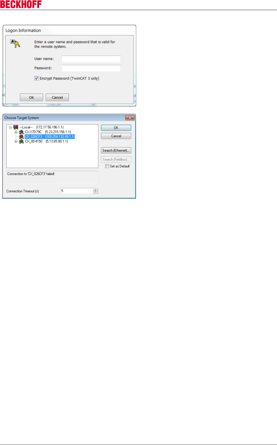
Advanced system characteristics
Servo Drives AX5000 111
Version: 2.4
Enter the required password (The Beckhoff default
password for Windows 7 is "1").
Confirm with OK.
Close the Add Route window with Close (6).
Select the newly added target system.
Press OK to confirm your selection.
→ The target system is selected.
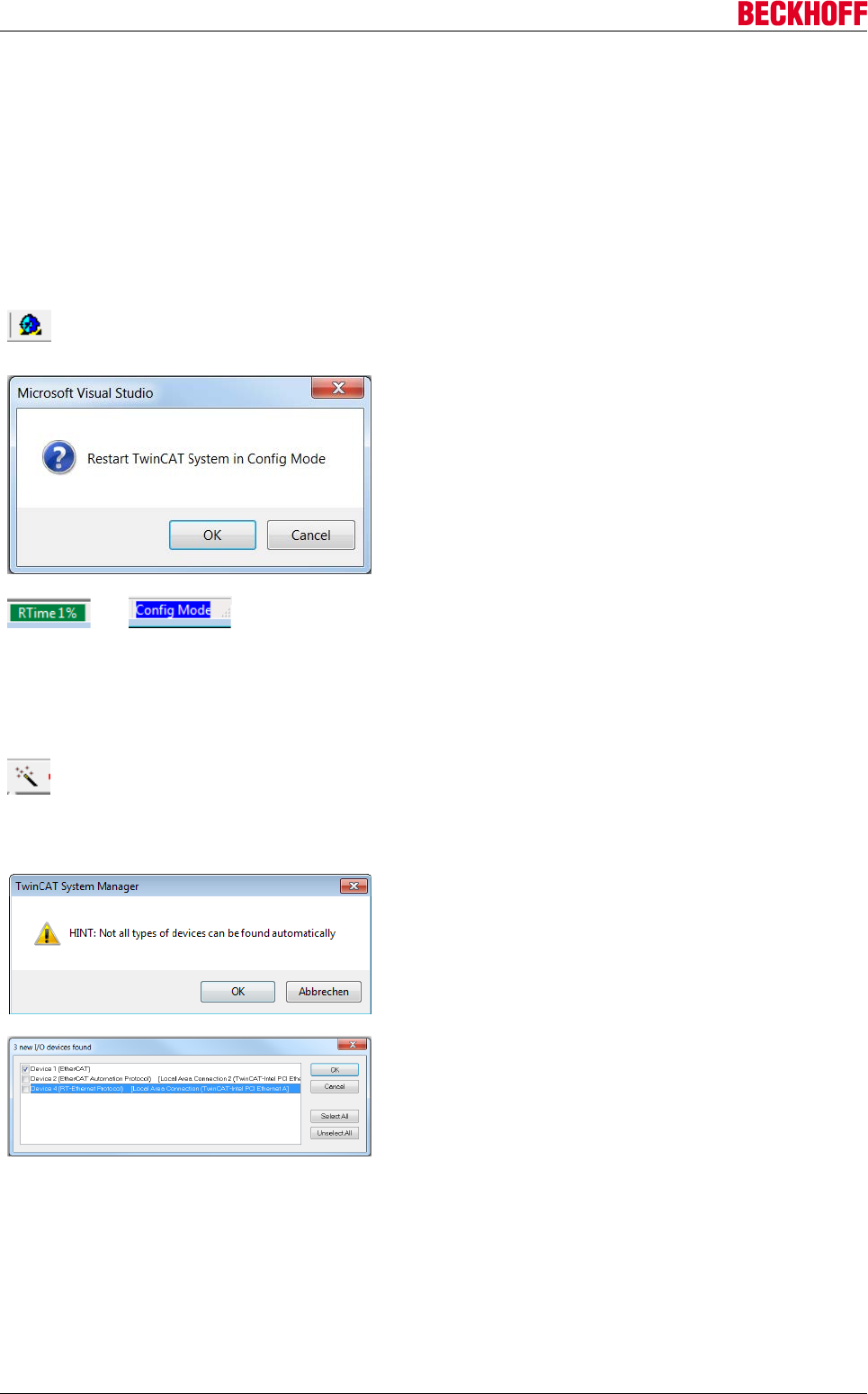
Advanced system characteristics
Servo Drives AX5000112 Version: 2.4
Adding EhterCAT master and drives
You can implement your drive in your TwinCAT project either manually or via an automatic scan. It is
advisable to scan, because this will insert the required drive devices directly into the project.
TwinCAT in ConfigMode
To start the scanning process, TwinCAT must be in ConfigMode. ConfigMode is one of several TwinCAT
states, which is displayed in the status bar of the System Manager. If the text is highlighted in blue,
ConfigMode is activated, and the scan can be started. If the text is highlighted in green or red, follow these
steps:
Click the blue gear icon in the toolbar.
You will see a query regarding the state change to be
carried out.
Confirm the state change with OK.
→
TwinCAT switches to ConfigMode, and the text highlighting
in the status bar turns blue.
TwinCAT is in ConfigMode.
Start drive scanning
If the right target system and ConfigMode are enabled, the scan can be started.
In the System Manager select I/O - Configuration → I/O
Devices.
Press the Scan in the toolbar or right-click on I/O Devices
and select Scan Devices….
In both cases, the following sequence starts:
Close the information window with OK.
Select the devices to be automatically added to the
TwinCAT project.
As a minimum, select the device with the supplement
(EtherCAT).
Complete the selection with OK.
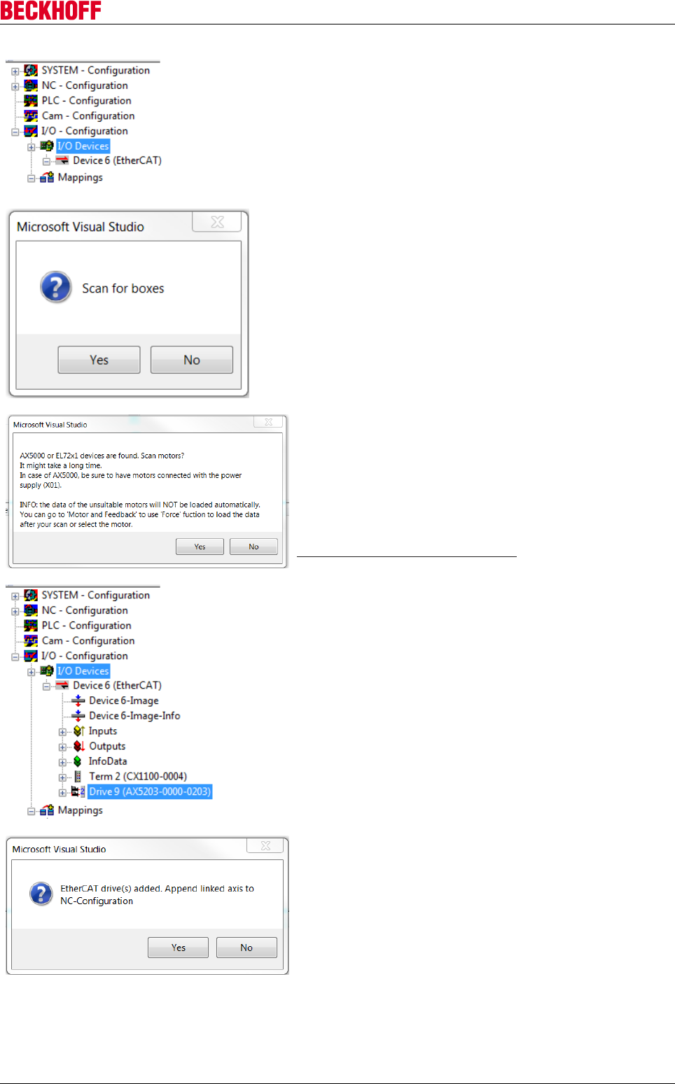
Advanced system characteristics
Servo Drives AX5000 113
Version: 2.4
In the System Manager all selected devices are shown
below the "I/O Configuration" icon.
Confirm the subsequent query whether the boxes should be
scanned with Yes
If the query is answered in the negative, no boxes /
EtherCAT slaves and therefore no drives are scanned.
The message regarding a found servo drive or servo
terminal can trigger a special scan for motors. Reads the
electronic type plates of the motors and enters the data
directly in the TCDriveManager.
Confirm the query with Yes to read the electronic type
plates.
If the query is not confirmed, no name plates are read. In
this case, the motor types must be entered manually. See
Determining the motor type [}115].
Wait for the scan to complete.
The System Manager then shows the servo drives and
terminals that were found. To control the motors via the
TwinCAT project, an NC or CNC axis configuration has to be
created.
Confirm the query with Yes to create an NC axis
configuration.
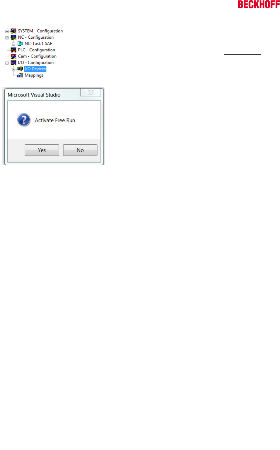
Advanced system characteristics
Servo Drives AX5000114 Version: 2.4
As a result of the automatic axis configuration creation, an
axis is added for each motor that was found and linked
accordingly.
If you require a CNC axis, close the window with No and
create the configuration manually. See Create NC axis
configuration [}118].
The created NC axis configuration is shown in the System
Manager.
Decline the request to activate Free Run with No.
→The drive is fully implemented in the TwinCAT project.
Also see about this
2Configuring devices [}115]
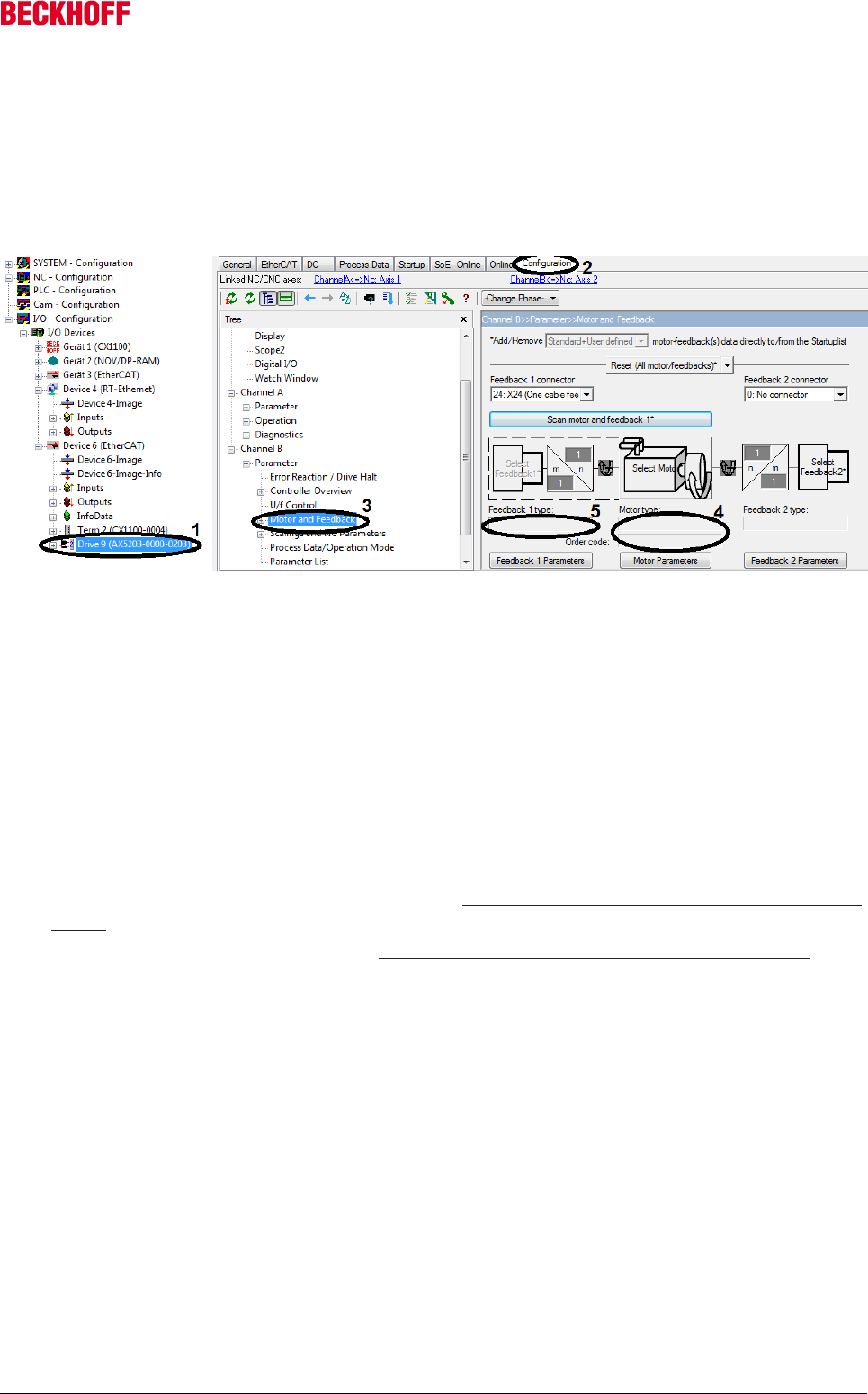
Advanced system characteristics
Servo Drives AX5000 115
Version: 2.4
Configuring devices
Determining the motor type
If a motor has no electronic name plate or the offer to scan for motors was declined, the motor type has to be
entered manually in the TCDriveManager.
Opening the TCDriveManagers
• In the System Manager, under I/O configuration → I/O devices, select the EtherCAT master, to which
the AX5000 units are connected. In this example select "Device 6" for the AX5000. Here, open "Drive
9" (1).
• Open the Configuration tab (2).
→ The TCDriveManager is open.
Motor settings
In the Configuration tab, a tree structure is shown on the left, which can be used to navigate to the individual
dialog pages. To check or set the motor type, edit the motor and feedback settings (3).
• Open either Channel A or Channel B → Parameter → Motor and Feedback (3).
The motor and feedback settings appear to the right of the tree.
If the fields Motor type (4) and Feedback 1 type (5) are empty, this may have two reasons:
1. The motor does not have an electronic name plate: Determine the motor without electronic type plate
[}116]
2. The motor has an electronic name plate: Determine the motor with electronic type plate [}117]
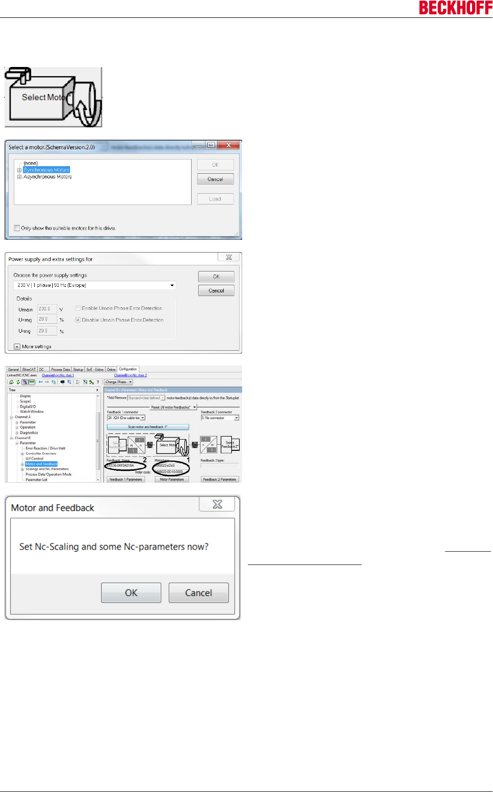
Advanced system characteristics
Servo Drives AX5000116 Version: 2.4
Determine the motor without electronic type plate
Press the Select Motor button to add the motor type.
A selection window opens, which shows all motor
versions and their properties.
Look for the motor of your drive in the list.
Confirm the selection with OK.
A further window appears, in which you have to
select or set the mains voltage to which the AX5000
is connected.
Make the required settings.
Confirm the selection with OK.
Selecting a motor type makes it appear in the Motor
type field (1). When the motor type is selected, the
encoder system used in this motor type also
becomes known and is shown in the field Feedback 1
type.
When the motor type is specified, a further query
appears, as to whether the NC or CNC parameters
relating to this axis should also be set.
If you confirm this message with OK, you will be
directed to the corresponding settings. See Create NC
axis configuration [}118].
→ The motor type is set.
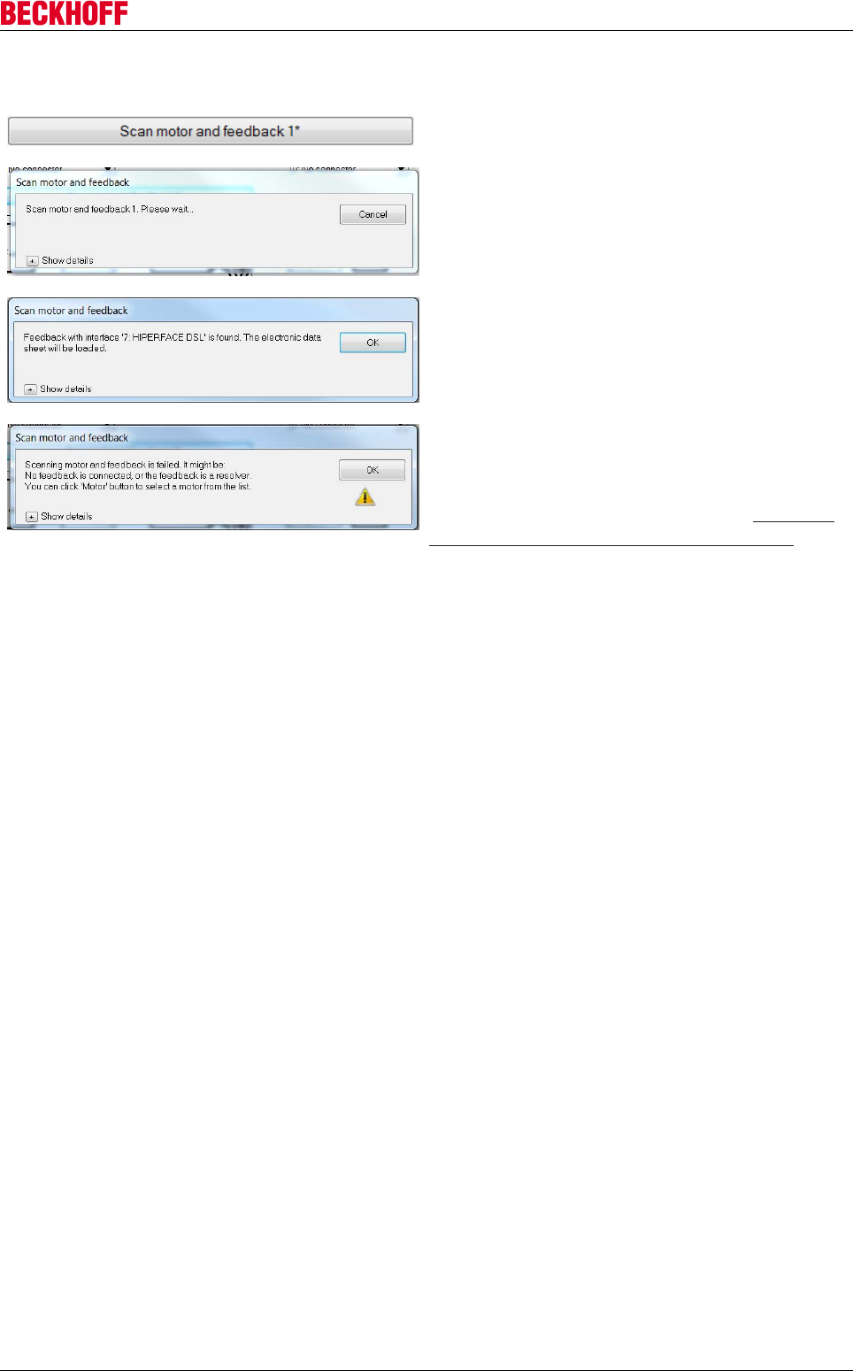
Advanced system characteristics
Servo Drives AX5000 117
Version: 2.4
Determine the motor with electronic type plate
Press the “Scan motor and feedback 1*” button.
Wait until the loading process is complete and the
window closes.
A window opens, in which the feedback type that was
determined is displayed.
Confirm the display with OK.
If this error message appears, instead of the
message about the determined feedback type, this
may be because your scanned motor has no
electronic name plate.
In this case, proceed as described under Determine
the motor without electronic type plate [}116].
→ The electronic name plate is read, and the motor type and the feedback type have been determined.
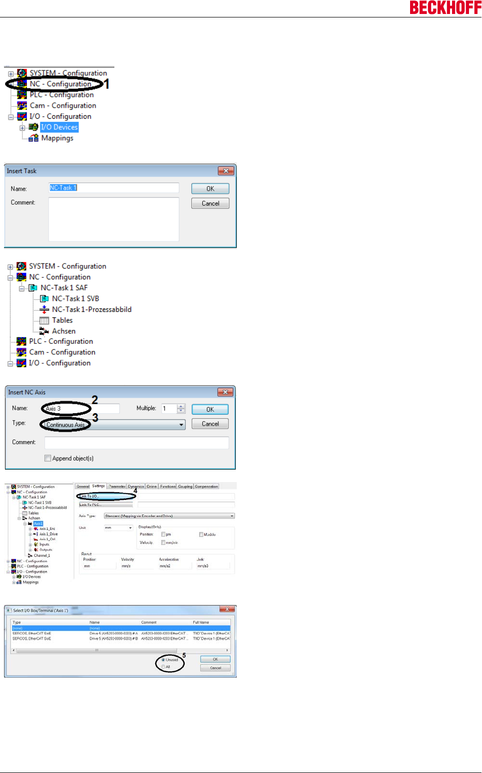
Advanced system characteristics
Servo Drives AX5000118 Version: 2.4
Create NC axis configuration
Right-click on NC – Configuration (1) in the System
Manager.
Select Insert Task…
Name the NC task
Confirm the entry with OK.
The System Manager expands below the NC
configuration to show the added NC task. The logical
NC axes can now be added below the Axes icon.
Right-click on Axes within the axis configuration.
Select Append Axis….
Enter a name for the NC axis (2).
Determine the axis type (3).
Confirm with OK.
In the System Manager the new axis appears with its
name within the NC axis configuration. Now link the
logical NC axes with the physical axes (the channels
of the respective AX5000).
Open Axis 1 in the System Manager tree
Switch to the Settings tab
Link the NC axis with the hardware axis via
Link To I/O... (4).
Select the AX5000 channel to be linked from the list
You can filter the list based on the channel link
status. The filter Unused (5) only shows channels that
are not linked. The setting All (5) shows all channels,
irrespective of their link status.
Confirm the selection with OK.
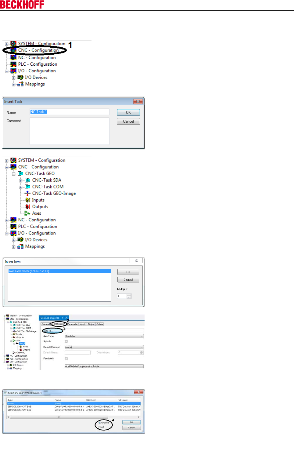
Advanced system characteristics
Servo Drives AX5000 119
Version: 2.4
Create CNC axis configuration
Right-click on CNC – Configuration (1) in the System
Manager.
Select Inert Task in the context menu…
Name the CNC task
Confirm the entry with OK.
The System Manager expands in the CNC
Configuration section to show the added CNC task.
The logical CNC axes can now be added below the
Axes icon.
Right-click on Axes within the axis configuration.
Select Append Axis….
Select the axis type from the list.
Confirm the selection with OK.
In the System Manager the new axis appears with its
name below the CNC task. Link the CNC axes with
the drive, in order to enable control.
Open Axis_1 in the System Manager.
Open the Configuration tab (2).
Link the CNC axis with the hardware axis via Link to
I/O... (3).
Select the axis to be linked from the list
You can filter the list based on the axis link status.
The filter Unused (4) only shows axes that are not
linked. The setting All (4) shows all axes, irrespective
of their link status.
Confirm the selection with OK.
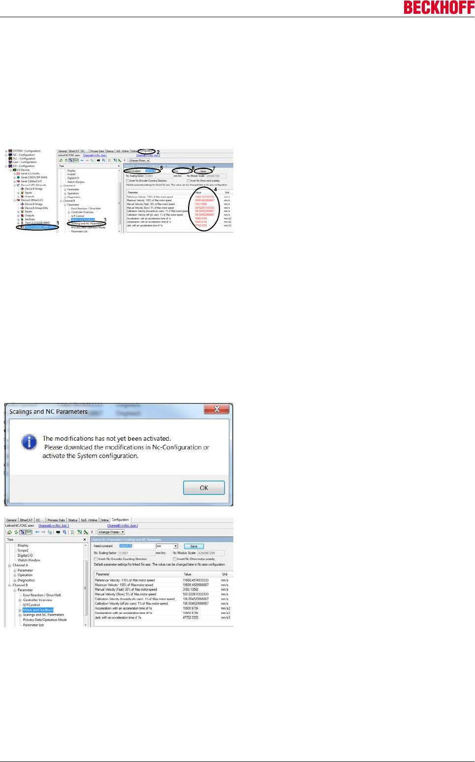
Advanced system characteristics
Servo Drives AX5000120 Version: 2.4
Specifying the scaling factor
The scaling factor is an application-related parameter, which is required for converting the position
representations between the NC and the AX5000. The NC is usually parameterized in the application unit
(e.g. degree). The AX5000 operates with a position representation of 2x increments per revolution (with x =
[20...31]). If, for example, a motor revolution corresponds to an application revolution (360 degrees), and x =
20 was selected, the resulting scaling factor is 360 degrees / 220.
.
In the System Manager tree, open I/O –Configuration
→ I/O Devices → Device 6 → Drive 9 (1).
Open the TCDriveManager via the Configuration tab
(2).
In the TCDriveManager tree select Channel B →
Parameter → Scalings and NC Parameters (3).
A table with different NC parameters and the
corresponding values (4) can be found to the right of
the TCDriveManager tree. Since the initial parameter
values are default values that were not explicitly
saved by the user, they are regarded as invalid and
therefore shown in red font. The individual parameter
values depend on the scaling factor, so that all
parameter values can be adjusted by modifying the
scaling factor.
Adjust the scaling factor via the field Feed constant
(5).
Select the unit (6).
Confirm the change with Save (7).
Acknowledge the information window with OK.
By confirming the change, the parameter values and
their units are adjusted to the new reference value
and appear in black font.
→ Your motor parameters are set correctly.
The configuration of Channel A follows the same procedure as for Channel B.
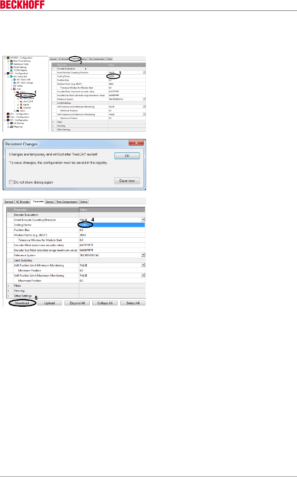
Advanced system characteristics
Servo Drives AX5000 121
Version: 2.4
Specifying velocities
Checking the scaling factor
In the System Manager, open NC- Configuration →
NC-Task 1 SAF → Axes → Axis 1 → Axis 1_Enc (1).
Open the Parameter tab (2).
Compare the value of the Scaling Factor (3) with the
value of the scaling factor.
If the value does not match the scaling factor, select
the field (3) and enter the scaling factor.
ATTENTION: Please ensure decimal points are used,
not decimal commas, as used in Germany!
Save changes permanently with Save now.
Wait a moment and close the window with OK.
The value change is indicated by the blue color of the
field (4).
Select the field with the changed value (4) to activate
the Download button (5).
Press Download (5) to save the change.
Another window appears:
Check the value for the second axis.
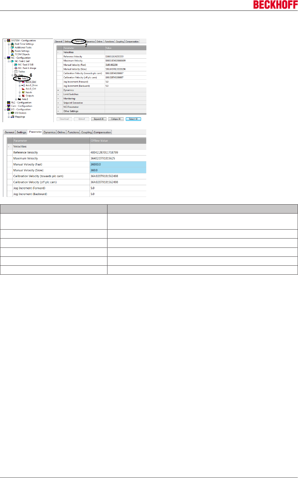
Advanced system characteristics
Servo Drives AX5000122 Version: 2.4
Setting the velocities
In the System Manager, open NC – Configuration →
NC-Task 1 SAF → Axes → Axis 1 (6).
Open the Parameter tab (7).
Set the velocities as required.
ATTENTION: Please ensure decimal points are used,
not decimal commas, as used in Germany!
The value change is indicated by the blue color of the
field.
→ The velocities are adjusted and take effect with the
next configuration.
Parameter Description
Reference Velocity The reference velocity must be set to a value ≥ the "maximum
velocity".
Maximum Velocity Maximum velocity (= max. velocity of the NC motion command)
Manual Velocity (Fast) Velocity in the manual test menu (F1 and F4)
Manual Velocity (Slow) Velocity in the manual test menu (F2 and F3)
Calibration Velocity (towards plc cam) Homing velocity
Calibration Velocity (off plc cam) Homing velocity
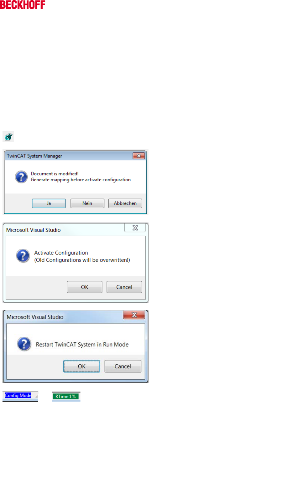
Advanced system characteristics
Servo Drives AX5000 123
Version: 2.4
Test mode
To test the TwinCAT project with all its settings on the drive, the settings have to be transferred to the
runtime system. To this end the whole configuration must be loaded into the runtime system of the target
hardware (e.g. a CX2000) and started there. After successful configuration, the motor control can be tested
manually in manual mode.
Before commissioning the manual control, it is advisable to check the control status of the drive.
Configure drive
Before you can start the controller, you must transfer the TwinCAT settings to the target system. To do this,
activate the configuration.
Click the Activate Configuration icon in the toolbar.
Confirm the warning with Yes.
Start the configuration with OK.
Start Run mode with OK.
→
Wait until the text highlighting turns green. Only then
is the application in Run mode.
→ All your settings were transferred to the runtime system. The drive is ready for operation.
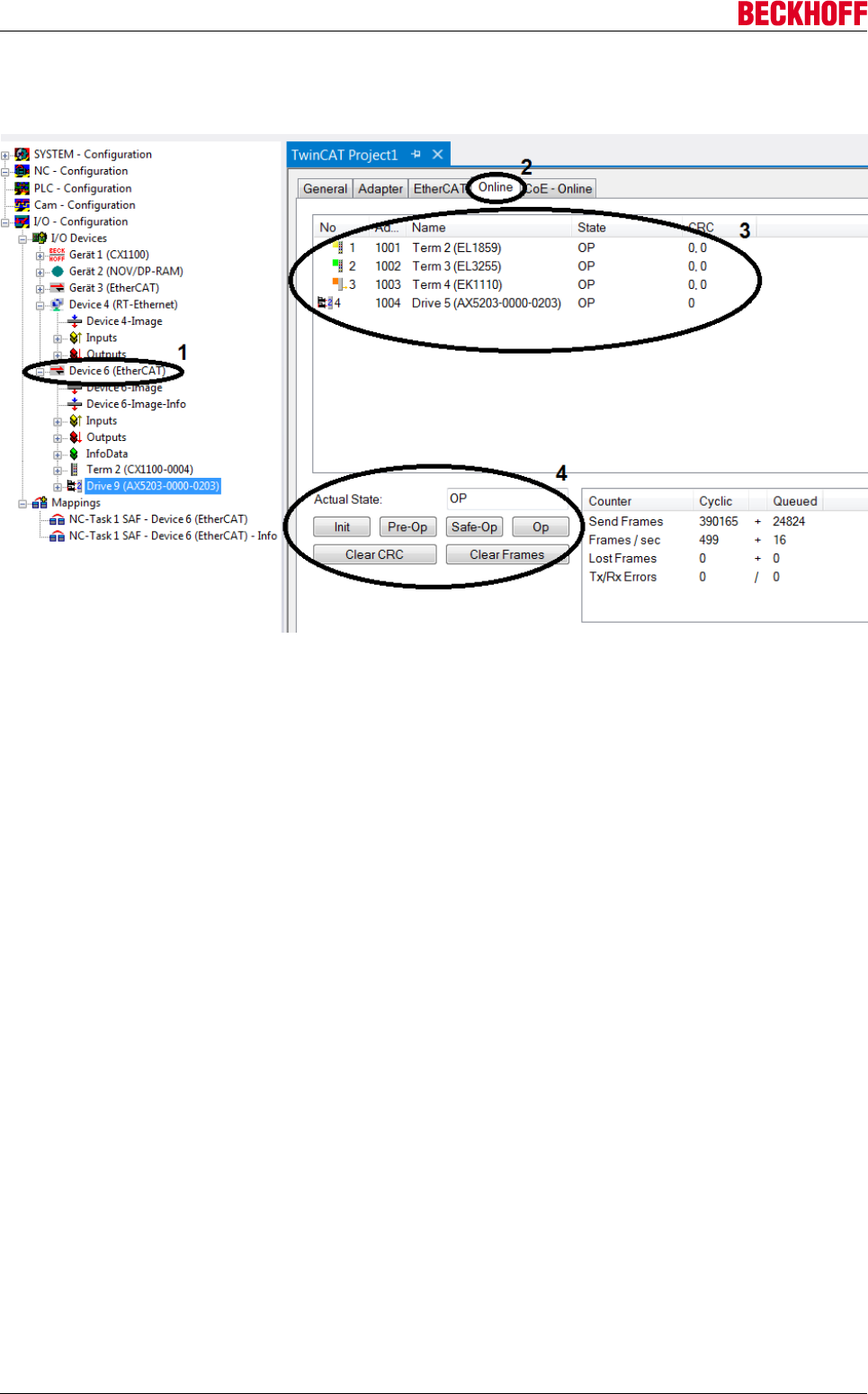
Advanced system characteristics
Servo Drives AX5000124 Version: 2.4
Checking the state
In the first step it makes sense to check the EtherCAT communication state of the system.
• In the System Manager, open I/O – Configuration → I/O Devices → Device 6 (EtherCAT) (1).
• Open the Online tab (2).
All slaves of the selected EtherCAT master and its communication states are displayed (3).
• Use the "buttons" in (4) to change the EtherCAT state of the master.
To ensure smooth operation, the states of all devices should be OP (see State status column the table
(3)).
→ Your system is checked and ready for operation.
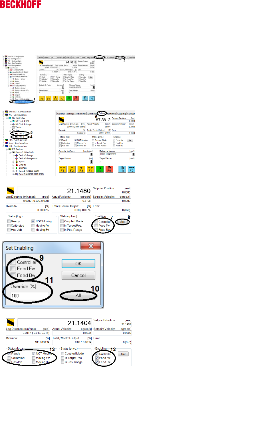
Advanced system characteristics
Servo Drives AX5000 125
Version: 2.4
Activating manual control
TwinCAT has a manual test menu, which allows you to start the drive manually in a test mode. The manual
test menu can be called up via the drive (Devices) or via the axis configuration.
Manual test menu for drive
In the System Manager, open I/O - Configuration → I/
O Devices → Device 6 → Drive 9 (1).
Switch to tab NC-B: Online (2) or NC-A: Online (3).
In this case you would test the drive for axis 2 by
selecting NC-B: Online (2). Select NC-A: Online (3) to
test axis 1.
Manual test menu for axis configuration
In the System Manager, select NC - Configuration →
NC-Task 1 SAF → Axes → Axis 2 (4) or Axis 1 (5).
Depending on which of the two axes is to be tested.
Open the Online tab (6).
Setting the drive enables
To operate the motors manually, manual drive control
must be enabled. The control is activated when
Enabling Controller (7) is active. In addition, the drive
requires Enabling Feed Fw** (7) activated for forward
travel, and Enabling Feed Bw (7) for reverse travel.
Use the Set button (8) to change the settings.
Use the All (10) button to set all settings and the
override (11) to 100%,
or all settings can be specified manually:
Tick the individual options (9) to activate them.
Enter the Override value (11).
The override (11) scaled the set velocity of the NC
motion command. The Override value can be
between 0% and 100%.
In the function view, the activated options are
indicated by ticks (12). In addition, the Status (log.)
(13) has changed with the activation, and the override
has been entered. The drive is ready for operation
and can be controlled with the manual mode menu.
*If this flag is set, the system tries to activate the drive control (of the AX5000) and to set the drive to a state
in which it follows the set value specifications of the NC. The "Ready" flag is set if the drive acknowledges
this request as successful.
**These so-called direction enables make it possible for the NC to accept motion commands in the
respective direction. The drive does not see these two flags.
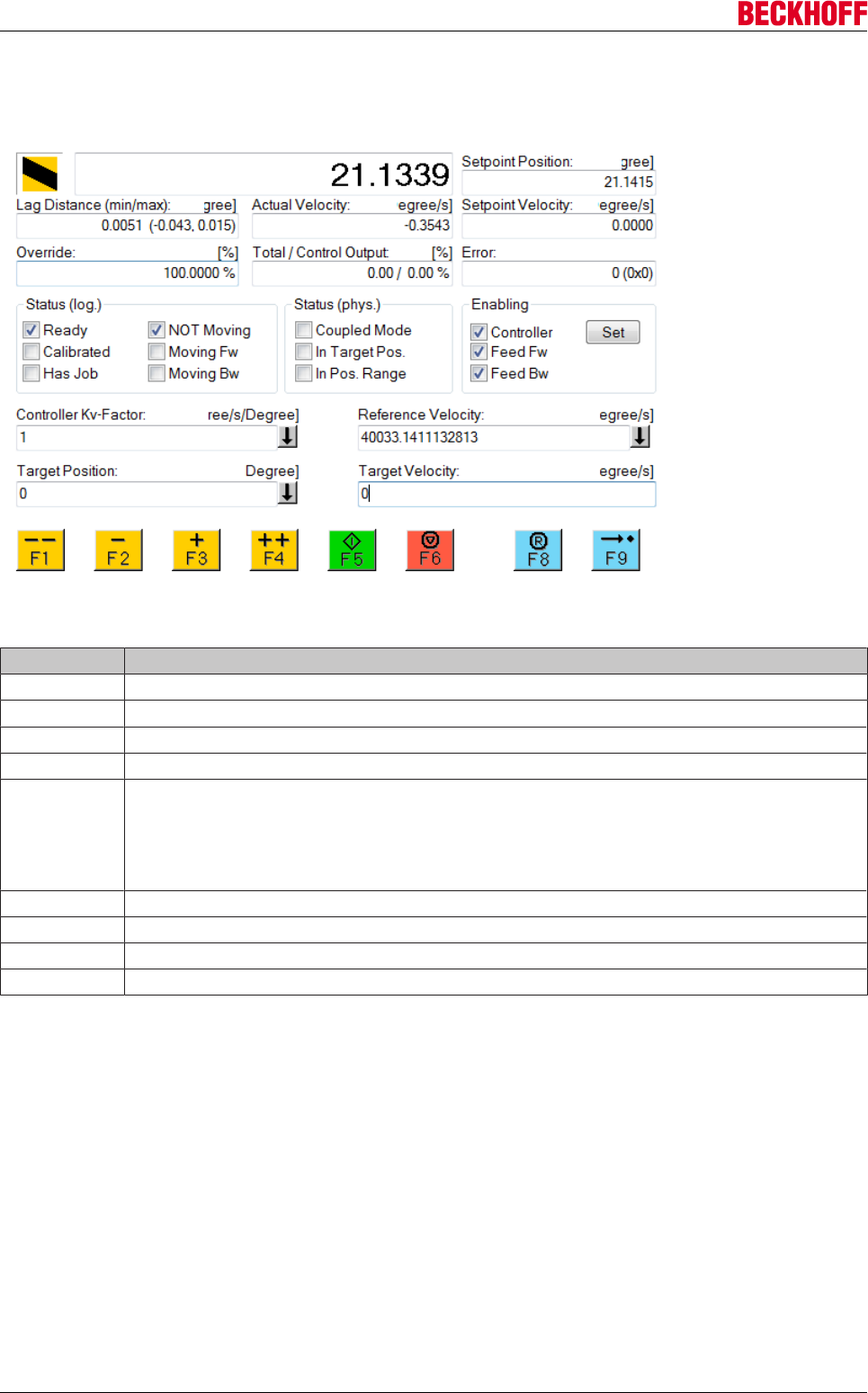
Advanced system characteristics
Servo Drives AX5000126 Version: 2.4
Manual control guide
The drive can be controlled using the buttons F1 to F9 and the fields Target Position and Target Velocity.
The following table provides an overview of all manual mode functions.
Function Description
F1 Reverse travel with Manual Velocity (Fast)
F2 Reverse travel with Manual Velocity (Slow)
F3 Forward travel with Manual Velocity (Slow)
F4 Forward travel with Manual Velocity (Fast)
F5 Start a direct travel command
• Enter the Target Position
• Enter the Target Velocity
• Start the travel command with F5
F6 Stop a direct travel command
F8 NC reset; the current motion command is aborted.
F9 Initiate homing (see TwinCAT documentation)

Advanced system characteristics
Servo Drives AX5000 127
Version: 2.4
Typical error messages
If you are in the manual mode menu and the position
value (2) is greyed out, this has the following reason:
A greyed out shown actual position for EtherCAT
drives indicates a "WC state error". In this case, the
WC state flag generated by the EtherCAT master is
"true", which means that the NC does not receive
valid position data from the drive.
The corresponding EtherCAT drive is probably not in
EtherCAT state SafeOp or Op. Further analysis is
required to ascertain why the drive is not in this state.
To investigate further, open the TCDriveManager via
Configuration (3). In the status bar, another error
code is shown at Diag Code (4). Check the drive
state (5). Select Diagnostics (6) from the tree
structure, in order to obtain further information about
the error. A list (7) on the right shows the whole error
history. Update the list via the button with the two
green arrows (8). Once the cause is identified and
corrected, reset the axis via the R button (9).
After a short time, the error indication will disappear
from the status line for the axis (10), and the drive will
be in OP state (operational) (11). Update the list of
error messages once more (8). It should contain no
more error messages (12).
In the manual mode menu for the axis, the position
value (13) is shown in black again.
Press the F8 button to acknowledge the NC error (14)
in the manual mode menu.
The drive is ready for operation again when the
"Ready" flag is set.
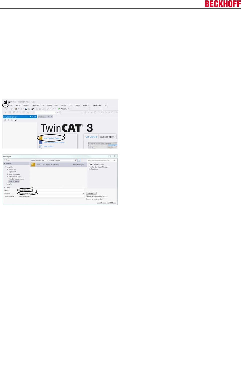
Advanced system characteristics
Servo Drives AX5000128 Version: 2.4
10.1.3.2 Commissioning under TwinCAT 3
This tutorial describes the procedure for commissioning the servo drive AX5000. All the steps shown are
based on TwinCAT Version 3. The individual chapters build on each other and should be followed
sequentially.
The tutorial shows a possible approach as an example. Alternative approaches are possible, which are
referred to in several places.
Creating a project
Open TwinCAT in the Windows Start menu.
Create a new project using the option New TwinCAT
Project ... (1) on the start page.
If TwinCAT opens without the start page shown on
the left, create a new project via the menu bar: File
(2) → New → Project.
In both cases, the window for creating a project will
open.
Assign project name (3).
Specify storage location (4).
Confirm with OK.
→ The new project appears with the Solution Explorer on the left and the workspace on the right.
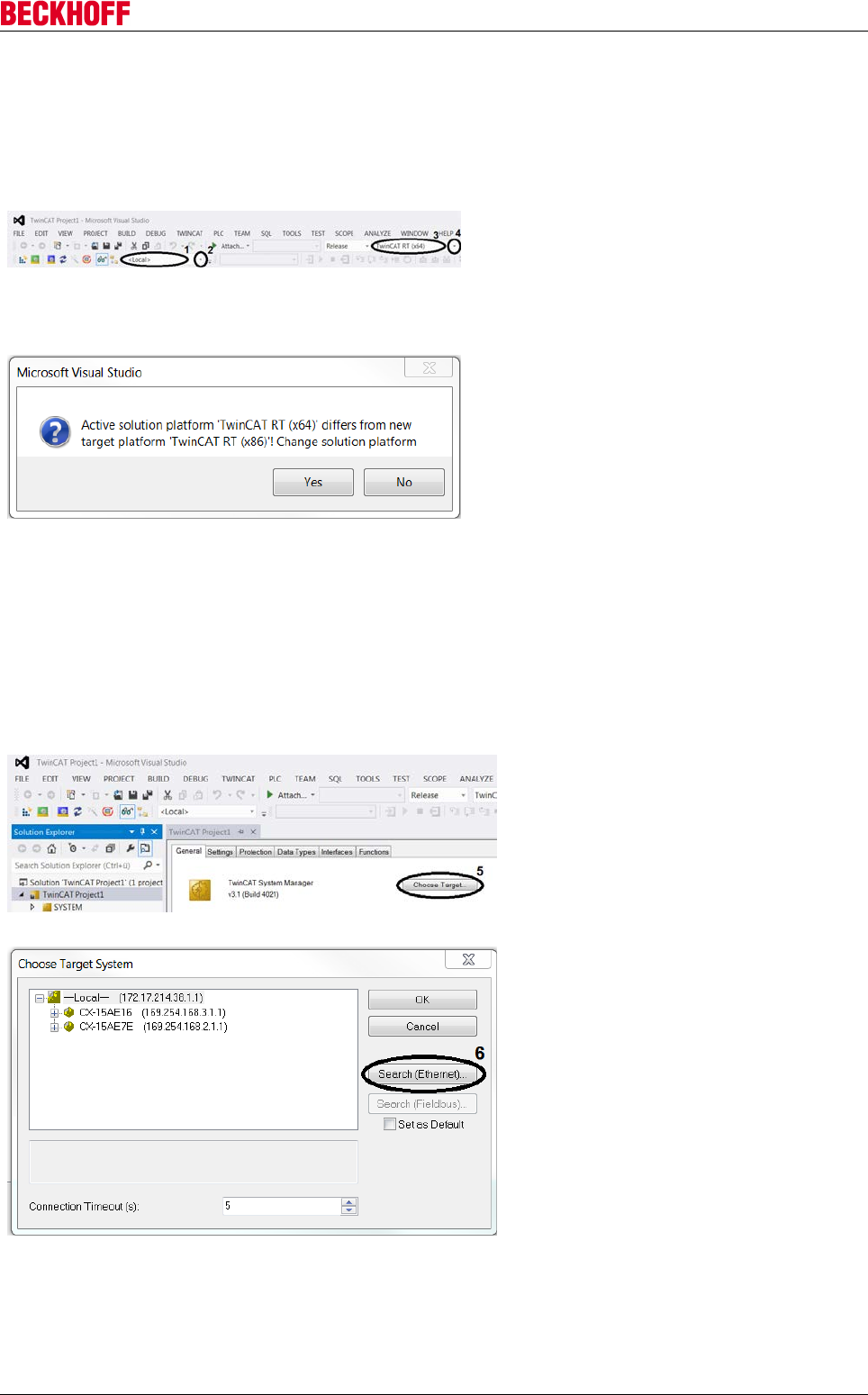
Advanced system characteristics
Servo Drives AX5000 129
Version: 2.4
Select target system
Target system available in selection list
In order to control your drive with TwinCAT, the software needs to communicate with the hardware. To this
end, the drive has to be selected as target system for the TwinCAT project.
The toolbar indicates which target system is
active (1).
Open the selection list using the small arrow (2)
to the right of the display window.
Select the drive as the target system.
Confirm query with Yes to change the platform
settings automatically.
This setting can be found in the toolbar (3).
If you answer No, this setting must be made
manually:
Open the platform selection list via the small
arrow (4) to the right of the display window (3).
Select a system-compatible platform.
→ The newly selected target system appears in
the display window (1).
→ The newly selected platform appears in the
display window (3).
Target system not available in selection list
If the target system is not in the list, follow these steps:
Choose Target System... select from the list,
or open System in the Solution Explorer and
press Choose Target... (5).
Both options take you to the Choose Target
System window. On the left is a list of all
target systems already in use. This list
should be identical to the previous selection
list.
Find more target systems via Search
(Ethernet) (6).
This opens the window Add Route.
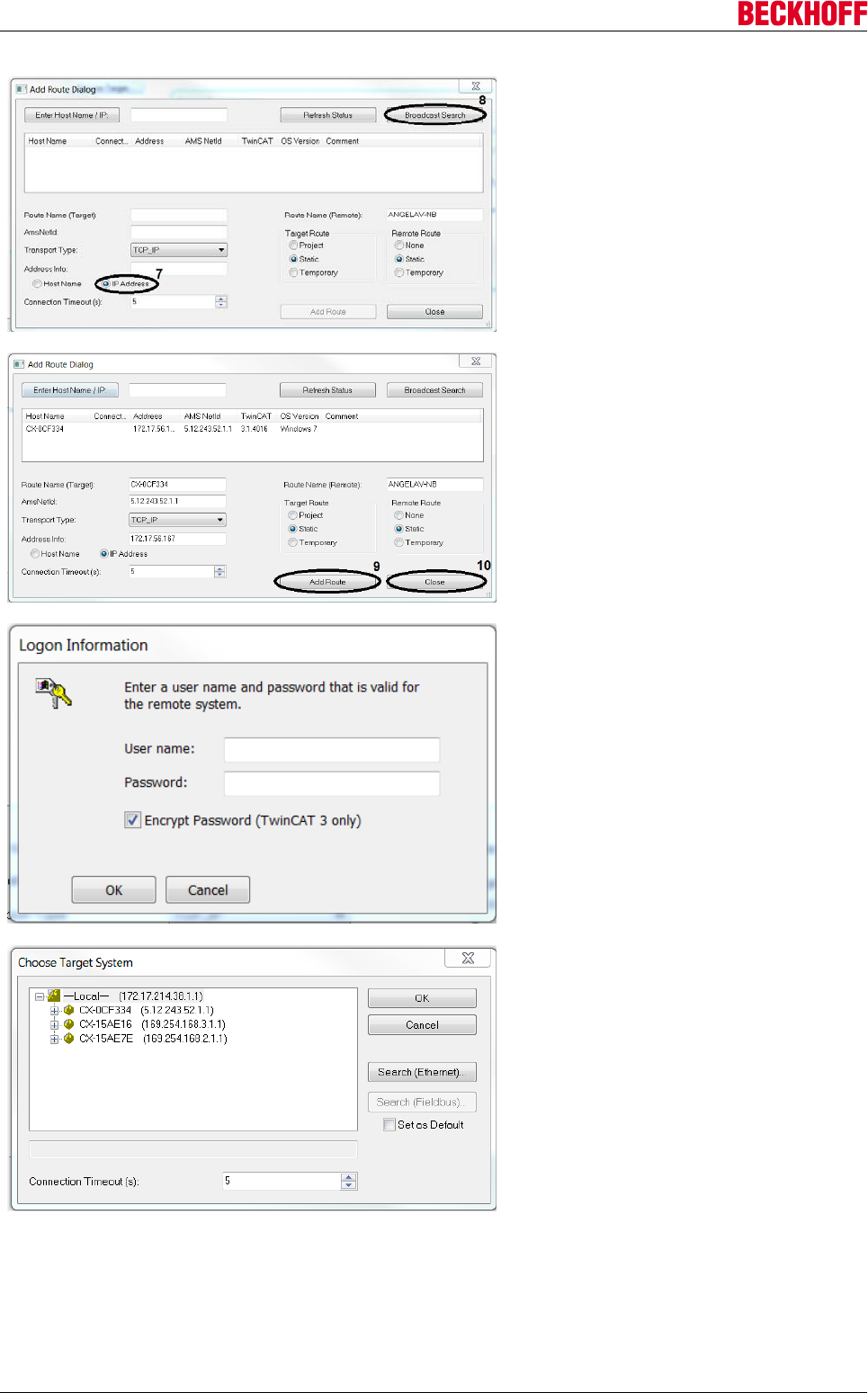
Advanced system characteristics
Servo Drives AX5000130 Version: 2.4
Before starting the search for more target
systems, set the IP address as Address Info
(7).
Start the search with Broadcast Search (8).
A list with all target systems that were found
is displayed.
Select the required target system.
Create link using Add Route (9).
You will see a password prompt for the
Embedded PC.
Enter the required password (The Beckhoff
default password for Windows 7 is „1“).
Confirm with OK.
Close the Add Route window with Close
(10).
Select the newly added target system.
Press OK to confirm your selection.
Because the platform to be used depends on
the respective target system, the platform
also needs to be adjusted if the target
system is changed.
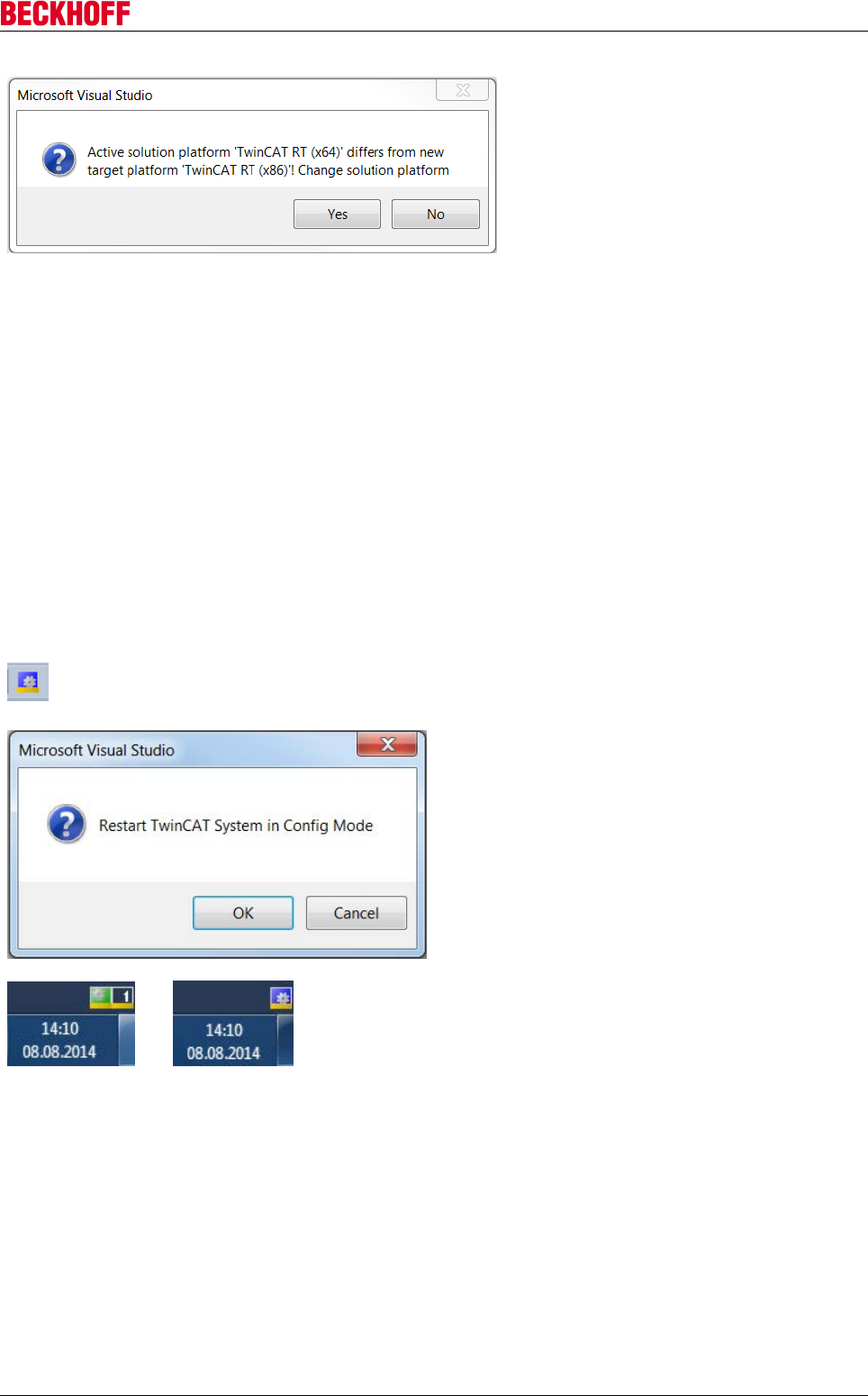
Advanced system characteristics
Servo Drives AX5000 131
Version: 2.4
Confirm query with Yes to change the
platform settings automatically.
This setting can be found in the toolbar (3).
If you answer No, this setting must be made
manually:
Open the platform selection list via the small
arrow (4) to the right of the display window
(3).
Select a system-compatible platform.
→ The newly selected target system
appears in the display window (1).
→ The newly selected platform appears in
the display window (3).
Implementing devices
You can implement your drive in your TwinCAT project either manually or via an automatic scan. It is
advisable to scan, because this will insert the required drive devices directly into the project.
TwinCAT in ConfigMode
To start the scanning process, TwinCAT must be in ConfigMode. ConfigMode is one of several TwinCAT
states, which can be identified by the small gear icon in the status bar at the bottom of the screen. If the icon
is blue, ConfigMode is activated, and the scan can be started. If the icon is green or red, follow these steps:
Click the blue gear icon in the toolbar.
You will see a query regarding the state change to be
carried out.
Confirm the state change with OK.
→
TwinCAT switches to ConfigMode, and the icon in the
status bar turns blue.
→ TwinCAT is in ConfigMode.
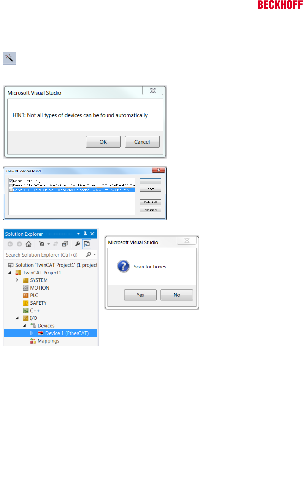
Advanced system characteristics
Servo Drives AX5000132 Version: 2.4
Start drive scanning
If the right target system and ConfigMode are enabled, the scan can be started.
In the Solution Explorer select I/O → Devices.
Press the Scan in the toolbar or right-click on
Devices and select Scan.
In both cases, the following sequence starts:
Close the information window with OK.
Select the devices to be automatically added to
the TwinCAT project.
As a minimum, select the device ending with
(EtherCAT).
Complete the selection with OK.
The Solution Explorer shows all selected
devices.
. Confirm the following query with
Yes. If you answer No, the scan is
aborted. The message regarding a
found servo drive or servo terminal
can trigger a special scan for
motors. This would read the
electronic name plates of the
motors and enter the data directly
in the TCDriveManager.
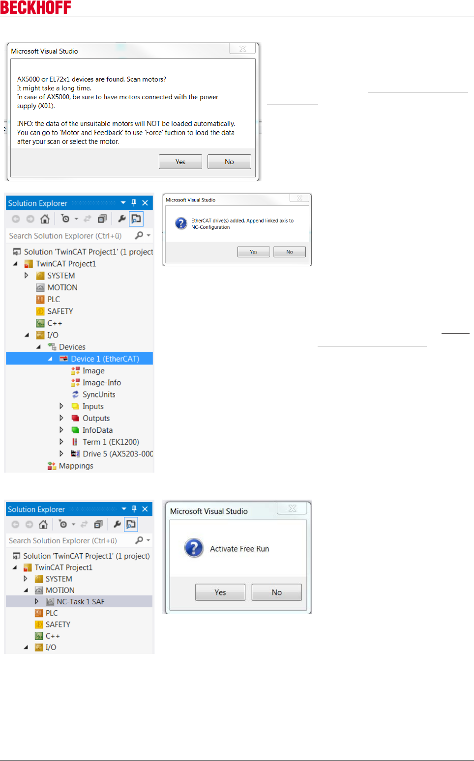
Advanced system characteristics
Servo Drives AX5000 133
Version: 2.4
Confirm the query with Yes to read the
electronic type plates.
If the query is not confirmed, no name plates
are read. In this case, the motor types must be
entered manually. See Determining the motor
type [}134].
Wait until the scan is complete.
The Solution Explorer then shows the servo
drives and terminals that were found.
To control the motors via the
TwinCAT project, an NC or CNC
axis configuration has to be
created. Confirm the query with
Yes to create an NC axis
configuration. As a result of the
automatic axis configuration
creation, an axis is added for each
motor that was found and linked
accordingly.
If you require a CNC axis, close the
window with No and create the
configuration manually. See Create
axis configuration [}137].
The created NC axis configuration
is shown in the Solution Explorer.
Decline the request to activate
Free Run with No.
→The drive is fully implemented in the TwinCAT project.
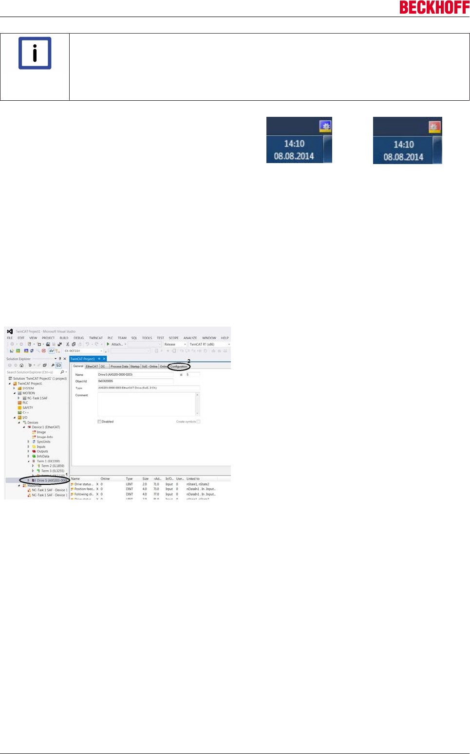
Advanced system characteristics
Servo Drives AX5000134 Version: 2.4
Note
Free Run mode
Free Run mode is used for synchronising the axes, if no NC is available. When NC is used,
a triggering task is activated, which synchronises the axes. This is not available if the sys-
tem is operated without NC. In Free Run mode a virtual task is created, which enables axis
synchronisation and reading of I/O data.
If the system is in Free Run mode, the blue and red
status bar icons flash alternately.
→
←
→
Also see about this
2Configuring devices [}134]
Configuring devices
Determining the motor type
If a motor has no electronic name plate or the offer to scan for motors was declined, the motor type has to be
entered manually in the TCDriveManager.
Opening the TCDriveManagers
In the Solution Explorer, open I/O → Devices →
Device 1 → Drive 5 (1).
Open the Configuration tab (2).
→ The TCDriveManager is open.
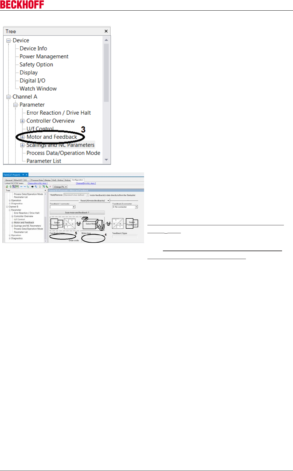
Advanced system characteristics
Servo Drives AX5000 135
Version: 2.4
Motor settings
Under the Configuration tab you will see a tree
structure on the left-hand side, which can be used for
all the required settings.
To check or set the motor type, edit the motor and
feedback settings (3).
Open either Channel A or Channel B → Parameter →
Motor and Feedback (3).
The motor and feedback settings appear to the right
of the tree.
If the fields Motor type (4) and Feedback 1 type (5)
are empty, this may have two reasons:
The motor does not have an electronic name plate:
Determine the motor type without electronic name
plate [}136]
The motor has an electronic name plate that was not
read: Determine the motor type with an electronic
name plate that was not read [}137]
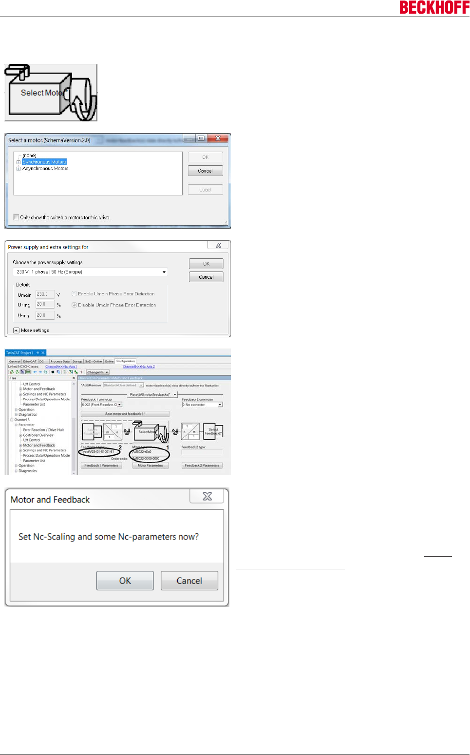
Advanced system characteristics
Servo Drives AX5000136 Version: 2.4
Determine the motor type without electronic name plate
Press the Select Motor button to add the motor type.
This opens a selection window that lists all the motor
type versions and their features.
Look for the motor of your drive in the list.
Confirm the selection with OK.
Another window appears, in which you can make
advanced settings.
Make the required settings.
Confirm the selection with OK.
Selecting a motor type makes it appear in the Motor
type field (1). The field Feedback 1 type (2) is
completed automatically, since for each motor type a
corresponding feedback type is stored in the
TCDriveManager.
Once the motor type has been specified, a further
query appears relating to the parameters of the axis
configuration.
If you confirm this message with OK, you will be
directed to the corresponding settings. See Create
axis configuration [}137].
→ The motor type is set.
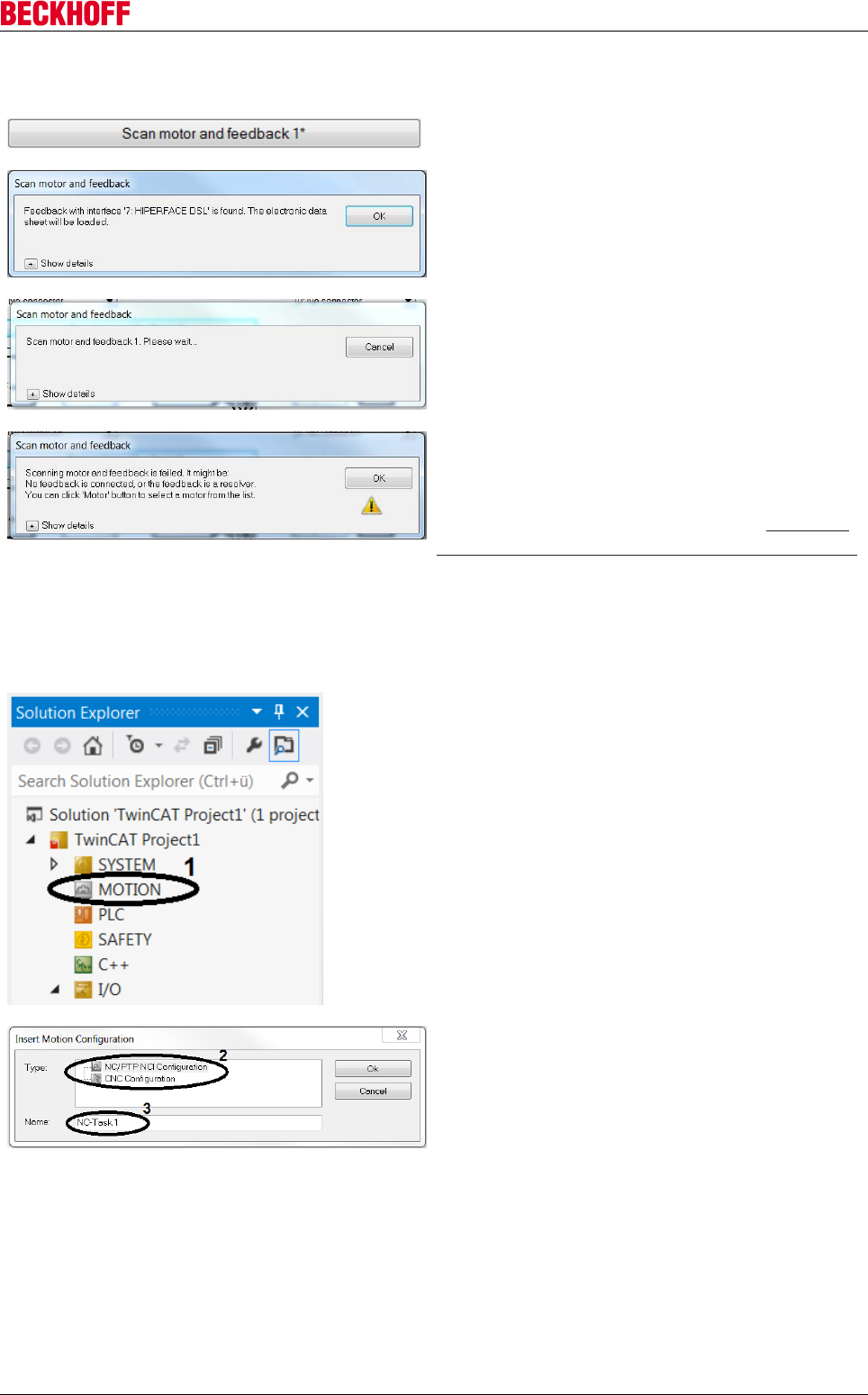
Advanced system characteristics
Servo Drives AX5000 137
Version: 2.4
Determine the motor type with an electronic name plate that was not read
Press the “Scan motor and feedback 1*” button.
Wait until the loading process is complete and the
window closes.
A new window opens, in which the feedback type that
was determined is displayed.
Confirm the display with OK.
If this error message appears, instead of the
message about the determined feedback type, this
may be because your scanned motor has no
electronic name plate.
In this case, proceed as described under Determine
the motor type without electronic name plate [}136].
→ The electronic name plate is read, and the motor type and the feedback type have been determined.
Create axis configuration
Right-click on Motion (1) in the Solution Explorer.
Select Add New Item....
Select Type (2) for your axis configuration.
Enter a name for the axis configuration (3).
Click OK to create the axis configuration.
The next steps depend on the axis type.
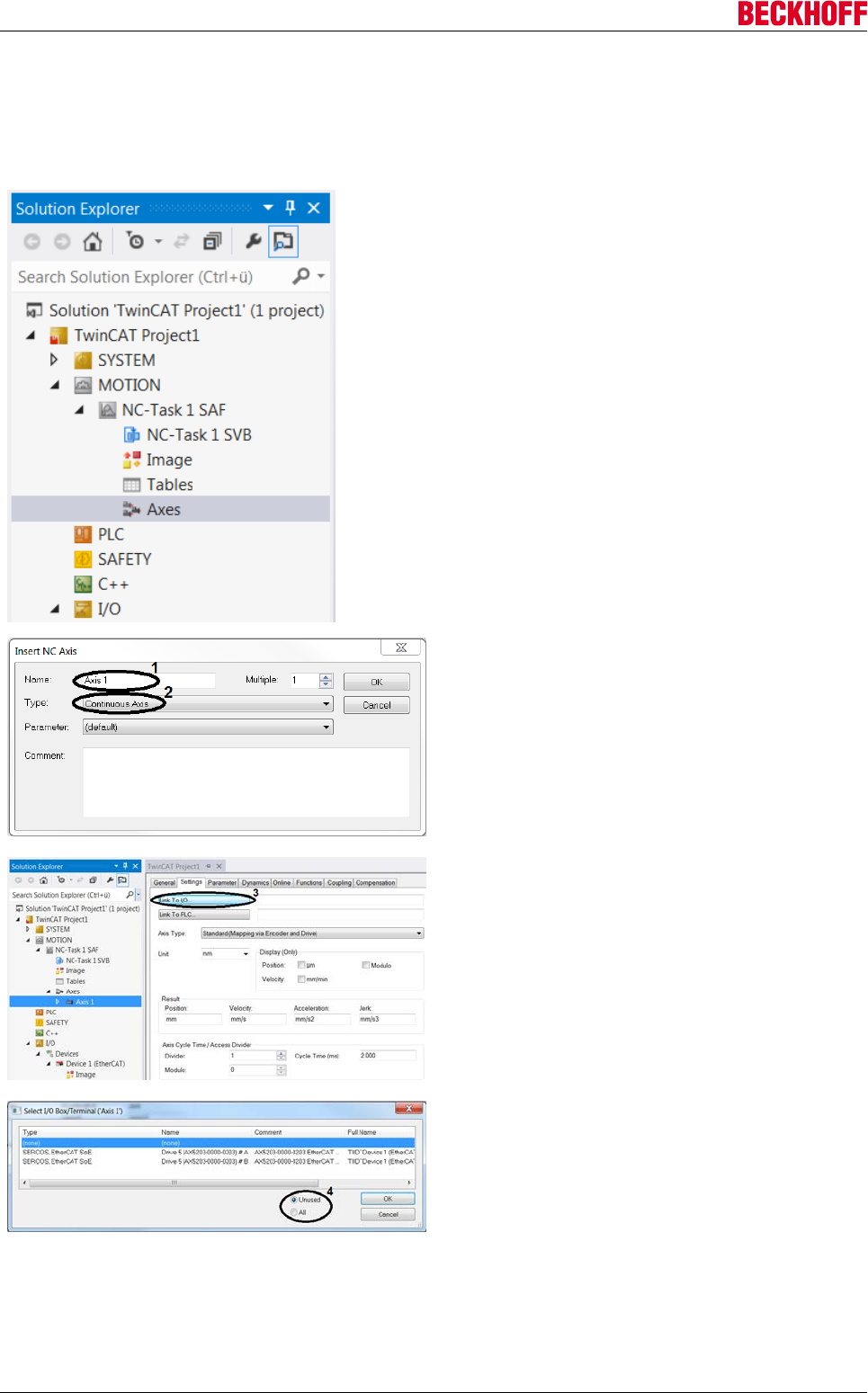
Advanced system characteristics
Servo Drives AX5000138 Version: 2.4
Creating an NC axis
If an NC axis configuration has already been created, the individual axes can be created and linked.
The Motion section of the Solution Explorer expands and shows the new NC axis configuration.
Right-click on Axes within the axis configuration.
Select Add New Item....
Enter a name for the NC axis (1).
Determine the axis type (2).
Confirm with OK.
In the Solution Explorer the new axis appears with its
name within the NC axis configuration. Link the
individual NC axes with the drive, in order to enable
control.
Open Axis 1 in the Solution Explorer.
Switch to the Settings tab.
Link the NC axis with the hardware axis via Link to I/
O... (3).
Select the drive to be linked from the list.
You can filter the list based on the axis link status.
The filter Unused (4) only shows axes that are not
linked. The setting All (4) shows all axes, irrespective
of their link status.
Confirm the selection with OK.
→ Your NC axis is successfully linked with the drive.
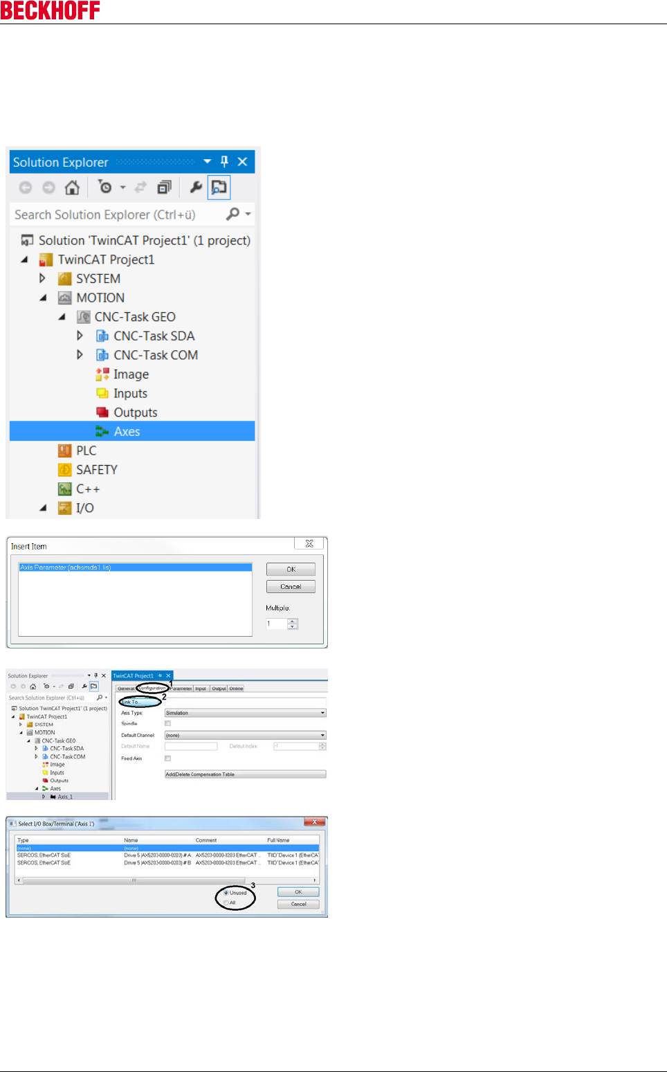
Advanced system characteristics
Servo Drives AX5000 139
Version: 2.4
Creating a CNC axis
If a CNC axis configuration has already been created, the individual axes can be created and linked.
The Motion section of the Solution Explorer expands and shows the new CNC axis configuration.
Right-click on Axes within the axis configuration.
Select Add New Item....
Select the axis type from the list.
Confirm the selection with OK.
In the Solution Explorer the new axis appears with its
name within the CNC axis configuration. Link the
individual CNC axes with the drive, in order to enable
control.
Open Axis_1 in the Solution Explorer.
Open the Configuration tab (1).
Link the CNC axis with the hardware axis via Link to
I/O... (2).
Select the drive to be linked from the list.
You can filter the list based on the axis link status.
The filter Unused (3) only shows axes that are not
linked. The setting All (3) shows all axes, irrespective
of their link status.
Confirm the selection with OK.
→ Your CNC axis is successfully linked with the drive.
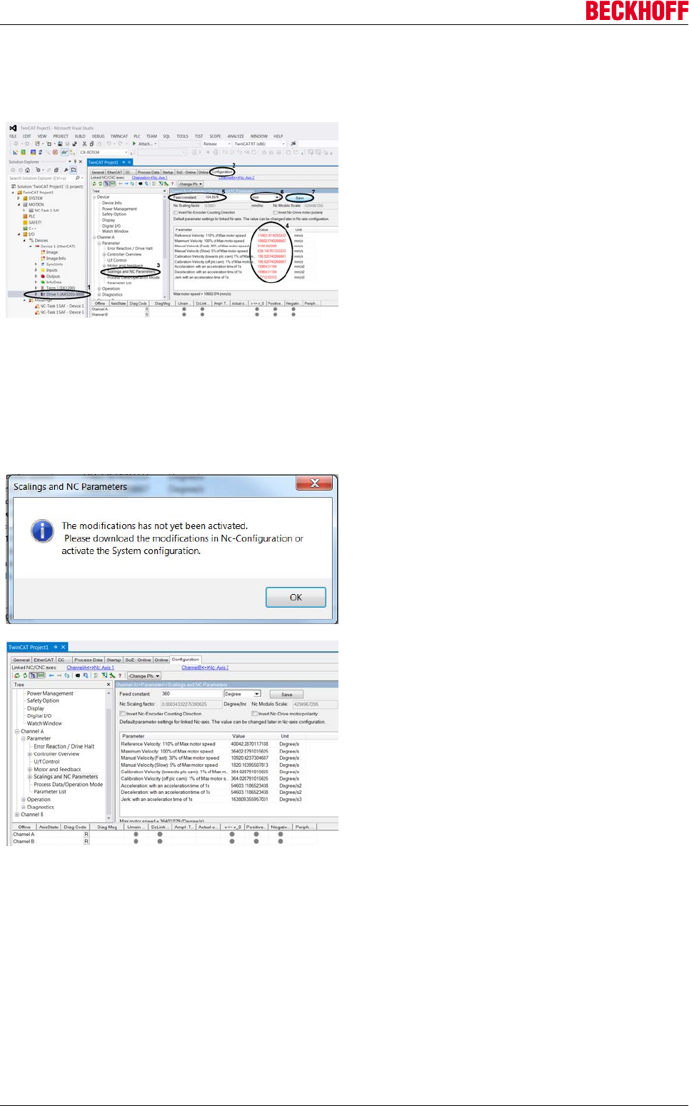
Advanced system characteristics
Servo Drives AX5000140 Version: 2.4
Specifying the scaling factor
The scaling factor is an application-specific parameter, which is required for converting position values.
In the Solution Explorer, open I/O → Devices →
Device 1 → Drive 5 (1).
Open the TCDriveManager via the Configuration tab
(2).
In the tree structure select Channel A → Parameter
→ Scalings and NC Parameters (3).
On the right next to the tree structure, there is a table
showing various motor parameters and associated
values (4). Since the initial parameter values are
default values that were not explicitly saved by the
user, they are regarded as invalid and therefore
shown in red font. The individual parameter values
depend on the scaling factor, so that all parameter
values can be adjusted by modifying the scaling
factor.
Adjust the scaling factor via the field Feed constant
(5).
Select the unit (6).
Confirm the change with Save (7).
Acknowledge the information window with OK.
By confirming the change, the parameter values and
their units are adjusted to the new reference value
and appear in black font.
→ Your motor parameters are set correctly.
The configuration of Channel B follows the same
procedure as for Channel A.
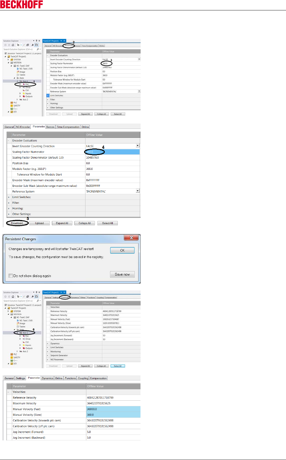
Advanced system characteristics
Servo Drives AX5000 141
Version: 2.4
Specifying velocities
Checking the scaling factor
In the Solution Explorer, open Motion → NC-Task 1
SAF → Axes → Axis 1 → Enc (1).
Open the Parameter tab (2).
Compare the value of the Scaling Factor Numerator
(3) with the value of the scaling factor.
If the value does not match the scaling factor, select
the field (3) and enter the scaling factor.
ATTENTION: Please ensure decimal points are
used, not decimal commas, as used in Germany!
The value change is indicated by the blue colour of
the field (4).
Select the field with the changed value (4) to activate
the Download button (5).
Press Download (5) to save the change.
Another window appears:
Save changes permanently with Save now.
Wait a moment and close the window with OK.
Also check the settings of Channel B.
Setting the velocities
In the Solution Explorer, open Motion → NC-Task 1
SAF → Axes → Axis 1 (6).
Open the Parameter tab (7).
Set the velocities as required.
ATTENTION: Please ensure decimal points are
used, not decimal commas, as used in Germany!
The value change is indicated by the blue colour of
the field.

Advanced system characteristics
Servo Drives AX5000142 Version: 2.4
Parameter Description
Reference Velocity Reference velocity of an analog servo drive
Maximum Velocity Maximum velocity (= maximum value of the field Target Velocity)
Manual Velocity (Fast) Velocity in the manual test menu (F1 and F4)
Manual Velocity (Slow) Velocity in the manual test menu (F2 and F3)
Calibration Velocity (towards plc cam) Homing velocity
Calibration Velocity (off plc cam) Homing velocity
→ The velocities are adjusted and take effect with the next configuration.
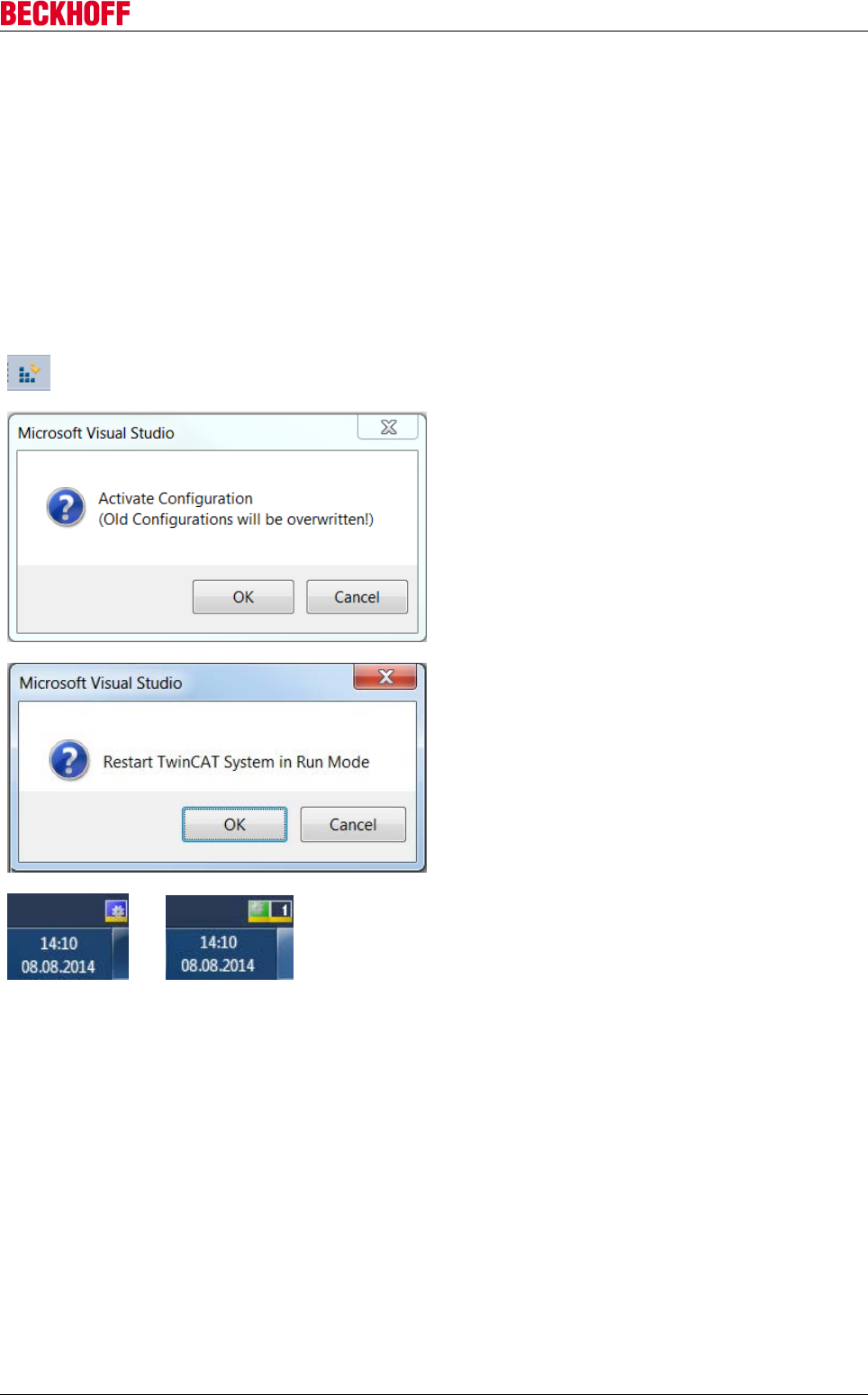
Advanced system characteristics
Servo Drives AX5000 143
Version: 2.4
Test mode
To test the TwinCAT project with all its settings on the drive, the settings have to be transferred to the drive.
To do this, the entire system must be configured. After successful configuration, the motor control can be
tested manually in manual mode.
Before commissioning the manual control, it is advisable to check the control status of the drive.
Configure drive
Before you can start the controller, you must transfer the TwinCAT settings to the drive. To do this, activate
the configuration.
Click the Activate Configuration icon in the toolbar.
Activate the configuration with OK.
All settings are applied to the drive.
Start Run mode with OK.
→
Wait until the blue gear icon in the status bar turns
green. Only then is the application in Run mode.
→ All your settings were applied to your drive. The drive is ready for operation.
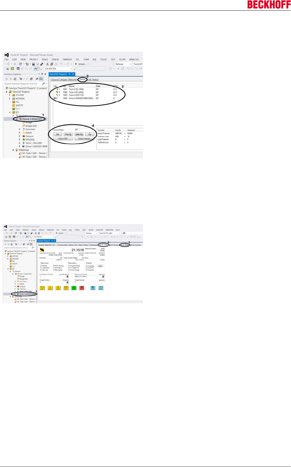
Advanced system characteristics
Servo Drives AX5000144 Version: 2.4
Checking the state
Before you operate the motor control, check the system states of the drive.
In the Solution Explorer, open I/O → Devices →
Device 1 (EtherCAT) (1).
Open the Online tab (2).
All drive devices are displayed (3).
The function keys (4) can be used to change the
states of all devices.
To ensure smooth operation, the states of all devices
should be OP (see State status column the table (3)).
→ Your system is checked and ready for operation.
Activating manual control
TwinCAT has a manual test menu, which allows you to start the drive manually in a test mode. The manual
test menu can be called up either via the drive (Devices) or via the axis configuration.
Manual test menu for drive
In the Solution Explorer, open I/O → Devices →
Device 1 → Drive 5 (1).
Switch to tab NC-B: Online (2) or NC-A: Online (3).
In this case you would test the drive for axis 2 by
selecting NC-B: Online (2). Select NC-A: Online (3) to
test axis 1.
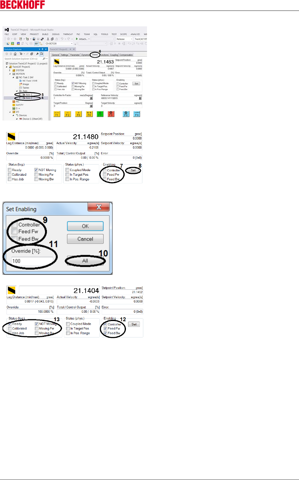
Advanced system characteristics
Servo Drives AX5000 145
Version: 2.4
Manual test menu for axis configuration
In the Solution Explorer, select Motion → NC Task 1
SAF → Axes → Axis 2 (4) or Axis 1 (5). Depending
on which of the two axes is to be tested.
Open the Online tab (6).
Setting the authorization permissions
To operate the motors manually, you have to enable
manual drive control. The control is enabled when
Enabling Controller (7) is activated. In addition, the
drive requires Enabling Feed Fw (7) activated for
forward travel, and Enabling Feed Bw (7) for reverse
travel.
Use the Set button (8) to change the settings.
Use the All (10) button to set all settings and the
override (11) to 100%,
or to set all settings manually:
Tick the individual options (9) to activate them.
Enter the Override value (11).
Override (11) overrides over all previous velocity
limits and indicates the ratio of the respective
velocity. The Override value can be between 0% and
100%.
In the function view, the activated options are
indicated by ticks (12). In addition, the Status (log.)
(13) has changed with the activation, and the override
has been entered. The motors are ready for operation
and can be controlled with the manual test menu.
→ Manual control is activated and can be used.
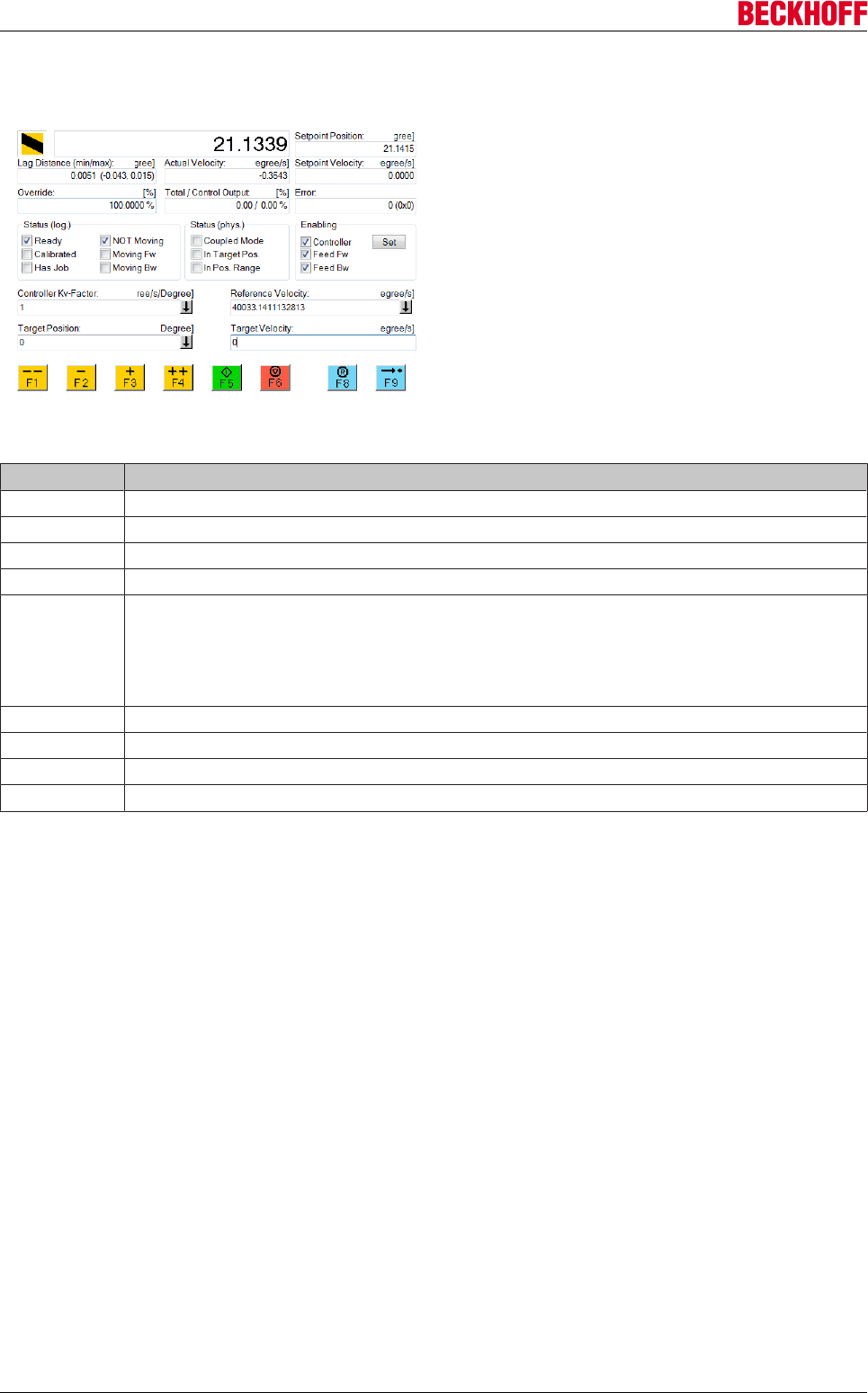
Advanced system characteristics
Servo Drives AX5000146 Version: 2.4
Manual control guide
The drive can be controlled using the buttons F1 to
F9 and the fields Target Position and Target Velocity.
The following table provides a brief overview of all manual mode functions.
Function Description
F1 Reverse travel with Manual Velocity (Fast)
F2 Reverse travel with Manual Velocity (Slow)
F3 Forward travel with Manual Velocity (Slow)
F4 Forward travel with Manual Velocity (Fast)
F5 Start a direct travel command
• Enter the Target Position
• Enter the Target Velocity
• Start the travel command with F5
F6 Stop a direct travel command
F8 Reset the control (if hand control has stopped responding)
F9 Trigger homing (see TwinCAT documentation)
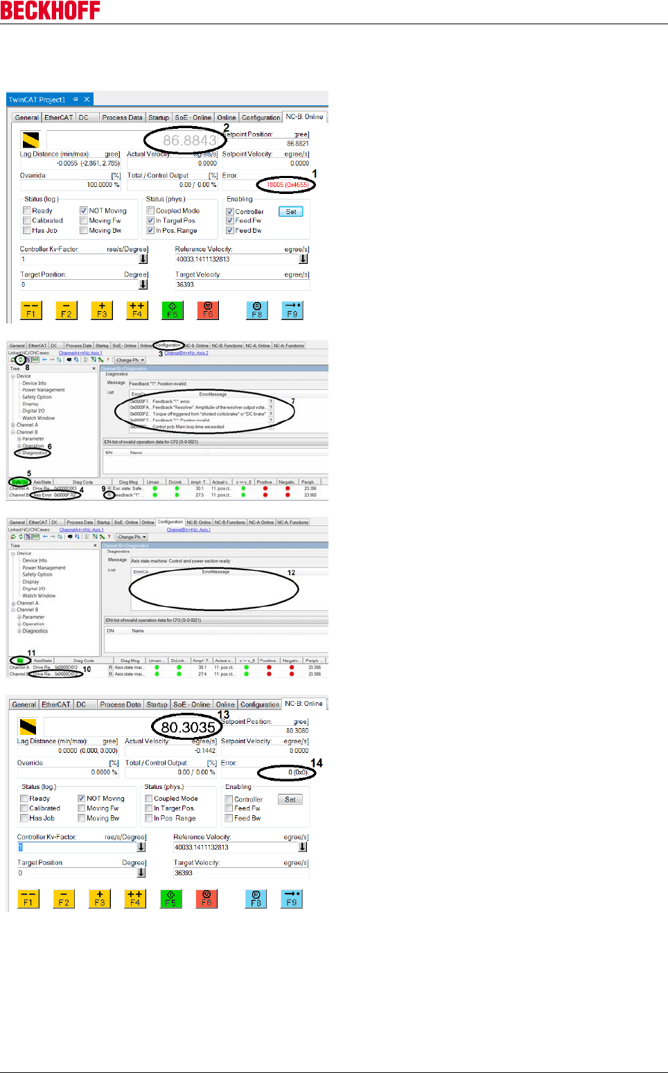
Advanced system characteristics
Servo Drives AX5000 147
Version: 2.4
Typical error messages
If you are in the manual test menu and the position
value (2) is greyed out, the manual test menu issues
an error message (1), and manual control is not
active. The error message gives no details about the
cause. To investigate further, open the
TCDriveManager via Configuration (3).
In the status bar for the axes, another error code is
shown at Diag Code (4). Check the drive state (5).
Select Diagnostics (6) from the tree structure, in order
to obtain further information about the error. A list (7)
on the right shows the whole error history. This list
can be used to identify the specific cause of the error
message. Update the list via the button with the two
green arrows (8), to show the latest error messages.
Once the cause is identified and corrected, reset the
axis via the R button (9).
After a short time, the error indication will disappear
from the status line for the axis (10), and the drive will
be in OP state (operational) (11).
Update the list of error messages once more (8). It
should contain no more error messages (12).
In the manual test menu for the axis, the position
value (13) is shown in black font once again.
Press the F8 button to reset the error (14) in the
manual test menu.
→ The drive is ready for operation again.
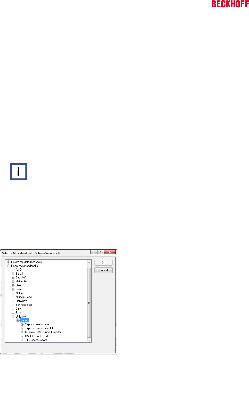
Advanced system characteristics
Servo Drives AX5000148 Version: 2.4
10.1.4 Linear motors
10.1.4.1 Commissioning of linear motor axes
Beckhoff Automation GmbH & Co. KG does not sell complete linear motor units. Magnetic plates and coil
parts are offered for sale. The machine manufacturer selects a linear measuring system to suit the
application. The assembly takes place at the machine manufacturer’s premises. This leads to various
selection options, whose results usually cannot be determined until commissioning. For example, the
direction in which the measuring system counts may not be known.
An incremental measuring system is often used with linear motors. This necessitates the use and
configuration of "Wake & Shake".
Requirements for commissioning
XML motor description
The XML description matching the motor is required for the commissioning of a linear motor on the AX5000
servo drive. The associated XML files for Beckhoff linear motors are contained in the TwinCAT setup
(AX5000 Download Package).
Note
XML files for third-party motors!
In the case of third-party motors the required XML descriptions can be generated with the
help of the "Tc Motor Data File Generator".
XML measuring system description
If a measuring system is used, it must also be present in the form of an XML description. Without this XML
description the measuring system does not appear in the TC Drive Manager selection list. A missing XML
description can be generated exclusively by Beckhoff Automation GmbH & Co. KG.
If an incremental (non-absolute) measuring system with sine/cosine or TTL signals is used, a corresponding
system can be chosen as "Unknown" from the list shown below.
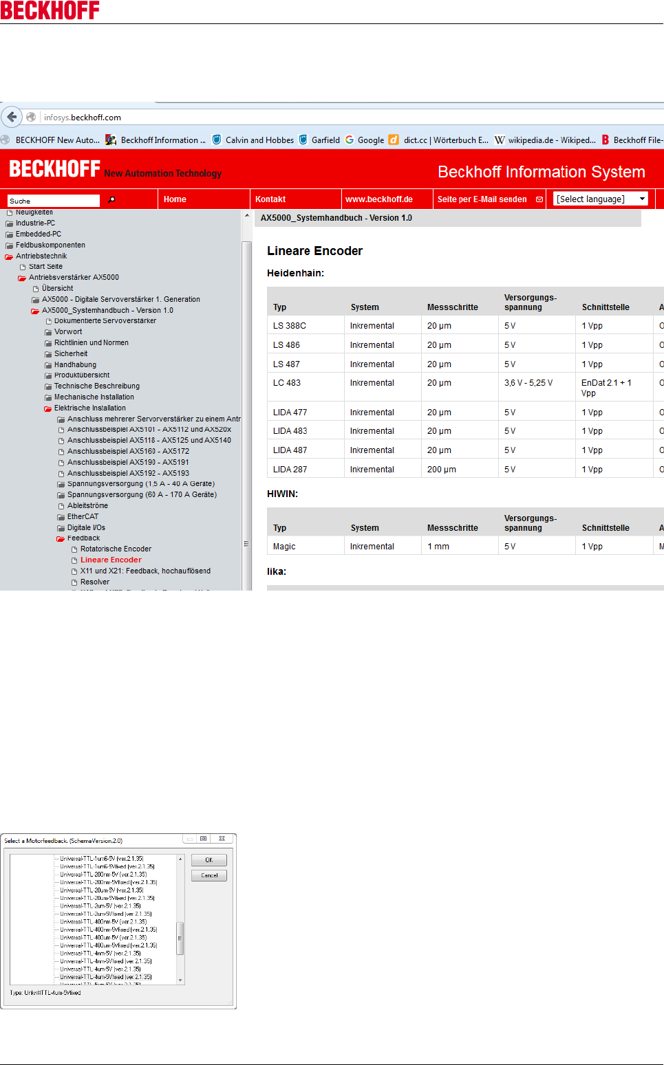
Advanced system characteristics
Servo Drives AX5000 149
Version: 2.4
An overview of feedback systems already used can also be found in the AX5000 system manual. The picture
detail below shows a selection of possible feedback systems that could come into question as a measuring
system.
Commissioning
Motor and feedback selection
The motor should be selected first, then the measuring system. This order ensures that the pole pair
distance of the linear motor is automatically taken into account in the feedback settings of the parameter.
In the case of linear encoders with TTL signals, a distinction must be made between the signal period and
the resolution. The manufacturers specify the resolution when evaluating all edges ("after quadrupling"). For
the AX5000 the signal period must be specified. A measuring system whose resolution is specified by the
manufacturer as 1 µm, for example, has a signal period of 4 µm and must be selected accordingly (picture
below):
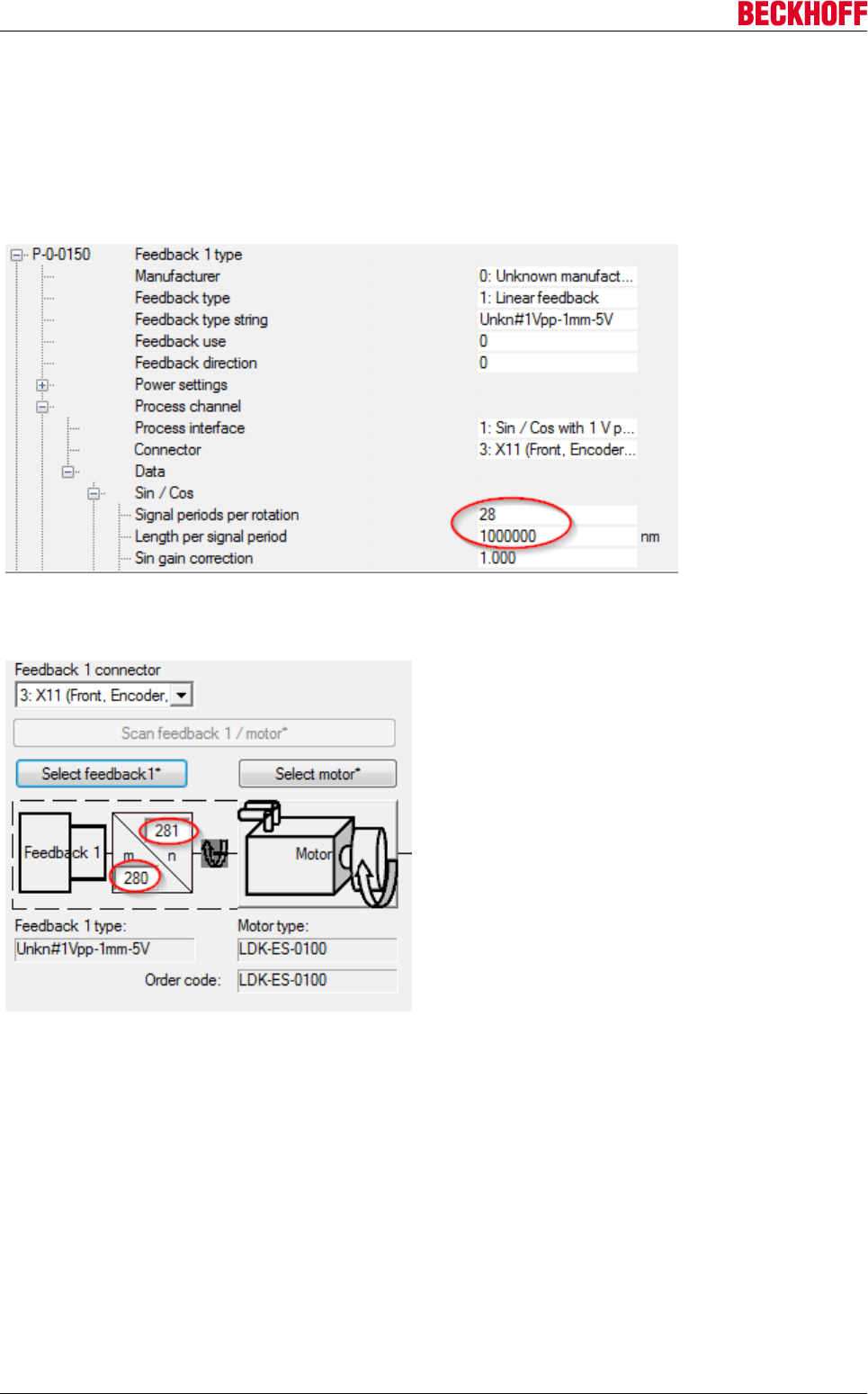
Advanced system characteristics
Servo Drives AX5000150 Version: 2.4
Motors with a pole pair distance that is not an integer represent a special case!
It is necessary to specify the "Signal periods per rotation" in parameter P-0-0150.
Sample:
With a pole pair distance of 28.1 mm and a sine period length of the linear encoder of 1 mm, a value of 28.1
would be correct. However, only integer values can be entered there. The Tc Drive Manager therefore enters
the value 28 in P-0-0150 (picture below):
The feedback gear unit is now automatically activated in order to correct the error described above (picture
below).
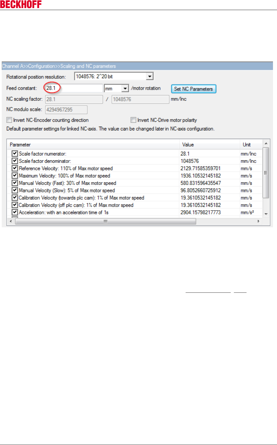
Advanced system characteristics
Servo Drives AX5000 151
Version: 2.4
Scaling factor
The pole pair distance of the linear motor in millimeters is to be entered in the field "Feed constant"(picture
below). After entering the correct “Feed constant”, all positions are specified in mm, all speeds in mm/s. A
non-integer input is possible at this point. 28.1 (decimal point!) is the correct value in the above example.
The values are confirmed in the NC with "Set NC Parameters". They are only valid when the configuration is
activated.
Checking the linear encoder
Once the motor and feedback have been selected and the scaling factor has been entered, the configuration
must be activated. Subsequently the measuring system must be checked. The AX5000 must not report any
feedback error when doing this. Please observe the notes in the section “Troubleshooting [}160]”.
Observe the position in the NC. Push the motor by hand during this procedure. The distance by which the
motor is pushed must be correctly displayed in the NC.
If a measuring system is used that can read out absolute and incremental signals, then the absolute and
incremental tracks must have the same counting direction. Therefore, the two tracks have to be compared
beforehand. The absolute position is read by the AX5000 only when switching on/restarting. Then it switches
over and evaluates only the incremental information (sincos or TTL signals).
Important: Up to this step the counting direction should not be inverted via a parameter at any point!
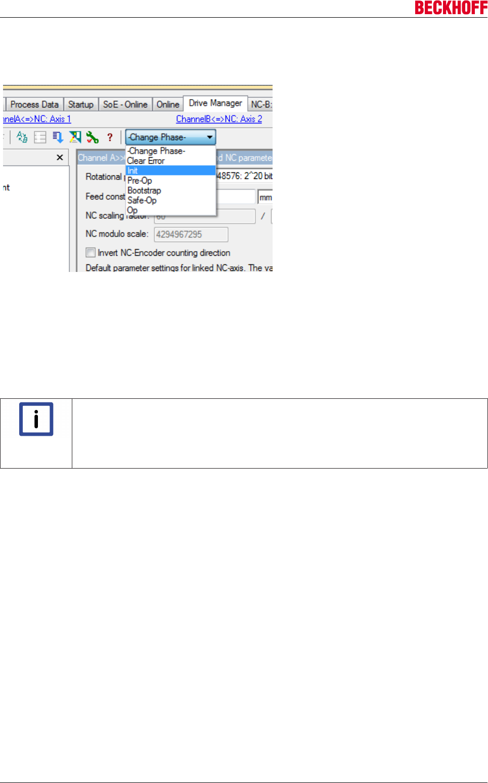
Advanced system characteristics
Servo Drives AX5000152 Version: 2.4
Now push the motor by hand. While doing this, observe the direction in which the position increases. Switch
the AX5000 to the "Init" state and then to the "Op" state (picture below). Using this procedure the absolute
position is read out again.
Note the absolute position read out. Now push the motor in the direction of the increasing position. Then
switch the AX5000 once again to the "Init" state and then to the "Op" state (picture below). If the absolute
position displayed after this procedure is larger than the one noted beforehand, both tracks are counting in
the same direction.
If a smaller position is displayed, the counting direction for the incremental encoder signals must be
reversed. This should be done by hardware means, for example by swapping the SIN+ and REFSIN signals
in the feedback connector.
Now repeat the test!
Note
Counting direction doesn’t correspond to the application!
If the counting direction of the linear encoder doesn’t correspond to the desired counting di-
rection in the application, this can be ignored at this point. The necessary settings can be
made at the end of the commissioning. The requirement for this is that the motor drives
without errors.
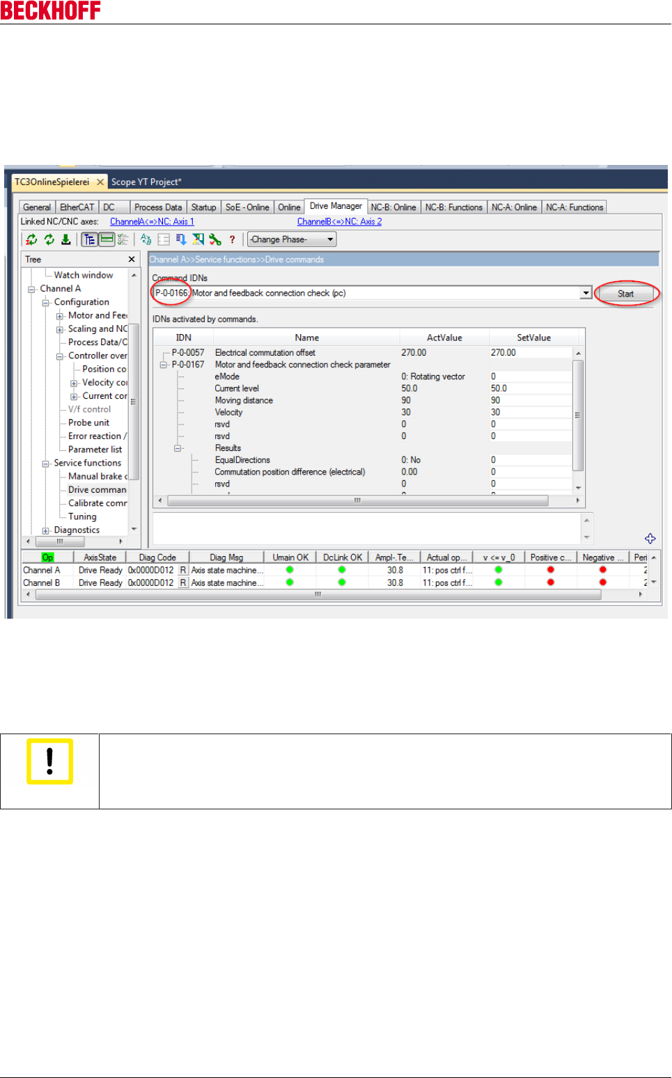
Advanced system characteristics
Servo Drives AX5000 153
Version: 2.4
Checking the motor phases and the encoder counting direction
If the absolute and incremental positions of the linear encoder have the same counting direction (or if there is
only an incremental position), the phase sequence of the motor can be compared with the encoder counting
direction. This can be checked using the command P-0-0166 "Motor and feedback connection
check" (picture below).
If the command P-0-0166 has been selected for checking the motor and feedback connection (picture
above), the input mask of parameter P-0-0167 appears. The parameters in the upper area should not initially
be changed.
The main voltage (e.g. 400 V) must be switched on in order to execute the command. The AX5000 must be
ready but not enabled. The "Diag Code" is 0x0000D012.
Attention
The execution of this command causes a movement of the motor!
Before confirming the following message with "Yes", make sure that the motor can move
freely and cannot cause any damage.
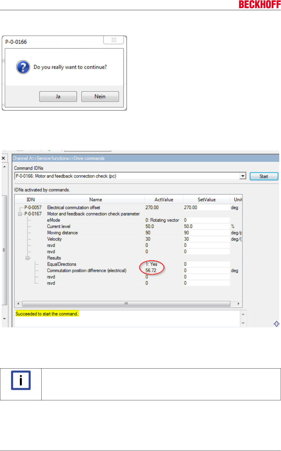
Advanced system characteristics
Servo Drives AX5000154 Version: 2.4
The following message appears during the first execution:
The linear motor first jerks and then makes a further movement a few seconds later.
If the command was executed successfully, the message "Succeeded to start the command" appears.
Values are hereby entered in parameter P-0-0167 "Results" (picture below).
It is important that the result "1:Yes" appears in the setting "Equal Directions" (picture above → red circle). If
"0:No" should appear there, two phases of the motor connection (AX5000 X13/X23) need to be swapped,
e.g. U and V.
The command can also be executed repeatedly.
Note
Further information can be found in the parameters:
P-0-0150; P-0-0166 and P-0-0167.
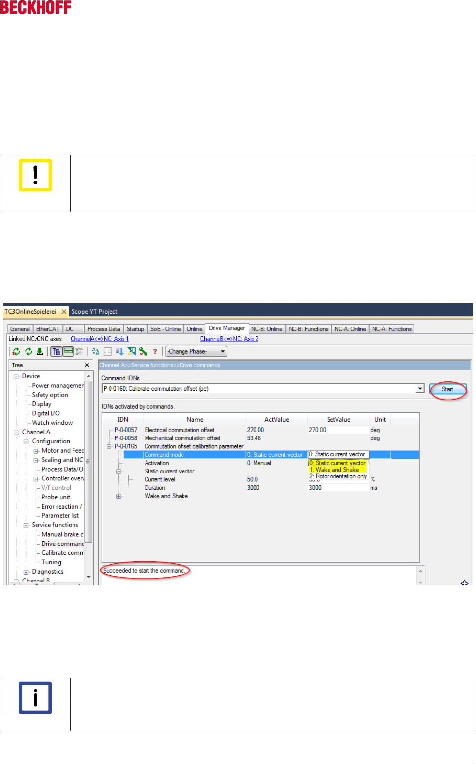
Advanced system characteristics
Servo Drives AX5000 155
Version: 2.4
Determination of the commutation offset
If the order of the motor phases matches the counting direction of the measuring system, the commutation
offset can be determined. In the case of absolute measuring systems, the commutation offset is only
determined once. The value is saved. In the case of incremental measuring systems, the "Wake & Shake"
must be configured. The commutation search then takes place automatically after each restart, when
enabling the servo drive for the first time.
With incremental measuring systems
Attention
Use of incremental measuring systems for vertical axes!
Beckhoff Automation GmbH & Co. KG urgently advises you not to use incremental measur-
ing systems with vertical axes. A reliable commutation search is not possible with this com-
bination!
Parameter P-0-0160 executes the commutation search. The behavior is configured with parameter
P-0-0165. The "Static current vector" method can be used for test drives. It is preferable to use "Wake &
Shake" in operation. It causes less movement of the axis. Both methods are executed using the command
"Start" (picture below → red circle). All settings should initially remain unchanged. The routine must be
completed without error. The message "Succeeded to start the command" (picture below → red circle)
should appear.
After successful execution of the command, the axis can be driven for test purposes; see below. Following a
successful test the entries "Command Mode" and "Activation" in parameter P-0-0165 should be changed to
"Wake & Shake" and "1:On enable request" respectively.
In most cases the default settings for "Wake & Shake" can be left unchanged. In many applications it is
useful to set the parameter "Commutation pos control: Kp" to 0. Details for this can be found under the
keyword "Electronic Commutation" in the Beckhoff Information System.
Note
Further information can be found in the parameters:
P-0-0160 and P-0-0165.
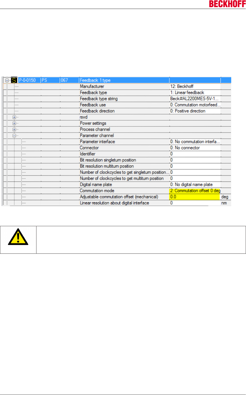
Advanced system characteristics
Servo Drives AX5000156 Version: 2.4
With absolute measuring systems
The AL2200-MES-Feedback indicates only the absolute position in relation to a pole pair. Homing is
necessary each time after switching on. The commutation offset only needs to be determined once and
saved. The commutation offset is determined in the same way as with other absolute measuring systems.
For that reason the AL2200-MES-Feedback is not described separately here.
Set the values for "Commutation Mode" and "Adjustable Commutation Offset (mechanical)" in parameter
P-0-0150 (see picture below).
The configuration must be activated to confirm the settings. Command P-0-0166 is used to set the electrical
commutation offset.
CAUTION
The execution of this command causes a movement of the motor!
Wait for the message "Succeeded to start the command"!
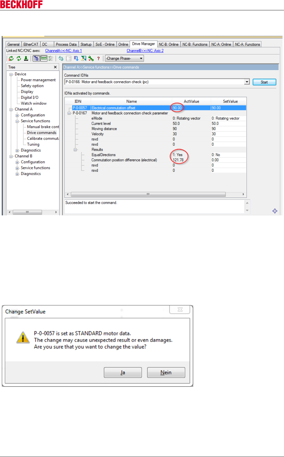
Advanced system characteristics
Servo Drives AX5000 157
Version: 2.4
"Yes" must appear as result under "Equal Directions".
Read the value for "Commutation position difference". Subtract this value from the value in P-0-0057
"Electrical commutation offset". The result, if positive, is the new value for P-0-0057. Add 360° to the result if
it is negative.
Sample:
90° - 121.78° = -31.78°
-31.78° + 360° = 328.22°
The result is the new value for P-0-0057 "Electrical commutation offset". Enter the value in SetValue and
confirm with <Enter>. Confirm the message that then appears with Yes (picture below).
The new value becomes active immediately upon pressing the download button (red arrow → picture below).
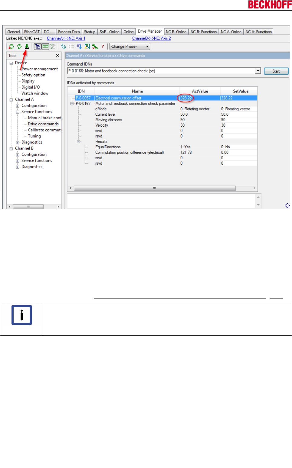
Advanced system characteristics
Servo Drives AX5000158 Version: 2.4
The value is displayed in the setting "ActValue" after the download is complete. Execute command P-0-0166
again!
The value for "Commutation position difference" should now lie within the range:
355 ... 360 = 0 ... 5.
If this value is displayed you have successfully completed the commutation search!
The offset value has already been adopted into the startup list with the download button.
If the value lies outside the range, P-0-0057 can be corrected again using the method described. If no useful
value is found, the more detailed check should be performed with the help of command P-0-0166. In this
case, please observe the section: "Checking the motor phases and the encoder counting direction [}153]".
Note
Further information can be found in the parameters:
P-0-0057, P-0-0150 and P-0-0166.
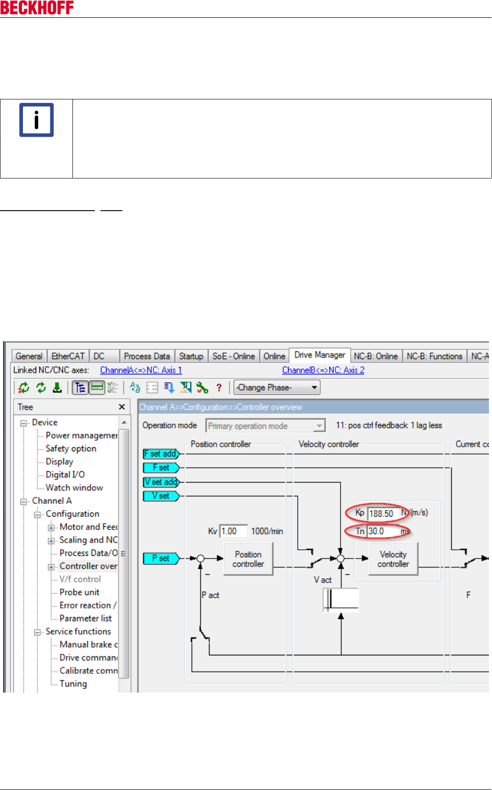
Advanced system characteristics
Servo Drives AX5000 159
Version: 2.4
Moving the axis for test purposes
Use the jogging buttons of the NC to move the axis at a slow speed. Do not execute the “Reversing
function”. Allow the motor to move by at least one pole pair in order to ensure that the commutation works
properly!
Note
Lag error if the velocity controller is not optimized!
It is possible for large lag errors to occur as long as the velocity controller has not been op-
timized!
• Test the travel movement at slow speeds and low acceleration.
• Allow a large lag error where possible.
If the axis travels only a few millimeters and then stops while drawing a high current, carry out the
commutation check [}153] using command P-0-0166.
Determination of the control loop parameters
The determination of the control loop parameters of a linear motor axis is done in the same way as with a
standard axis. For that reason only an abridged procedure is described here.
In most cases the preset proportional gain in the velocity/speed controller is much too small. This is set in
relation to the motor mass. In particular in the case of linear motors, the external mass can be large in
comparison with the motor mass. This case requires a significant enlargement of Kp.
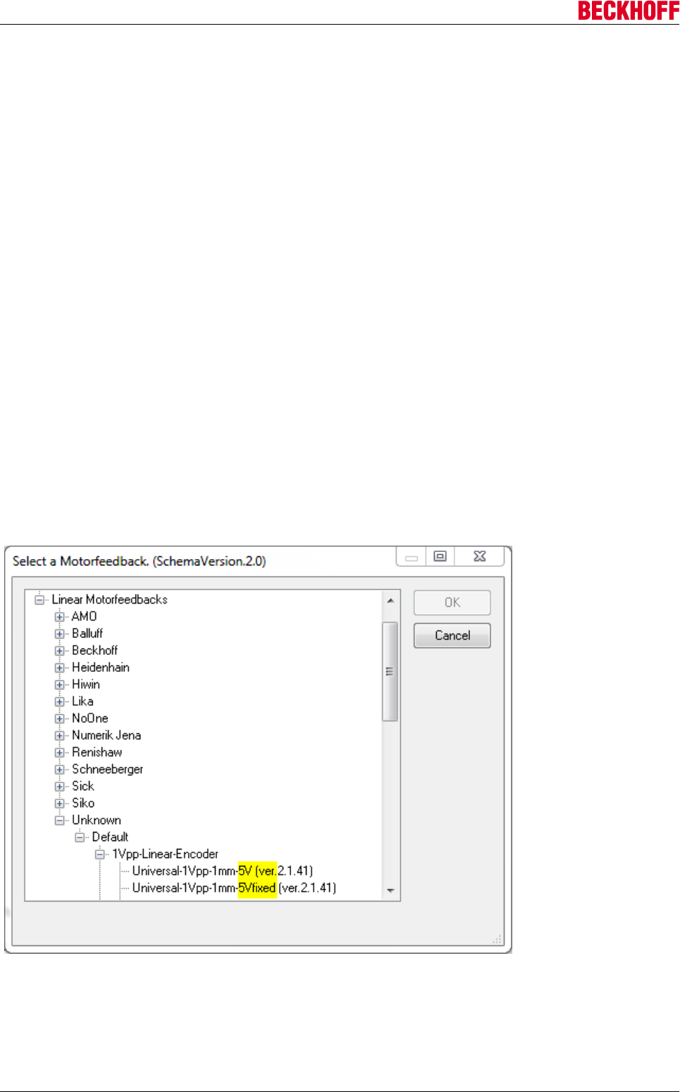
Advanced system characteristics
Servo Drives AX5000160 Version: 2.4
Abridged procedure:
1. Set Tn to ≥ 30ms (to reduce oscillation of the axis).
2. Start a reversing function at a moderate speed.
3. While the axis is moving, increase Kp in the "Controller Overview" window in steps of, for example,
20% up to the oscillation limit. (It is possible to check by axis noise).
4. Reduce Kp by about 20% until the oscillation reliably stops.
5. Also check that the axis doesn’t oscillate when it is at a standstill.
6. Reduce Tn
A value of between 5 ms and 10 ms is useful if the load is coupled normally.
The value must be increased if oscillations occur.
7. Kv = 1 in the position controller is usually okay. Reduce Kv (for example to 0.5) if the axis overshoots
the position after optimizing the velocity controller.
Kv can also be increased if an overly large lag error occurs.
Troubleshooting
Feedback error
It is important to read all messages in order to identify the causes of errors. In the case of feedback errors in
particular, the AX5000 normally outputs several error messages at once.
Errors in connection with the feedback power supply
Make sure when selecting a feedback system with the designation “Unknown” that the power supply is set
correctly (picture below)!
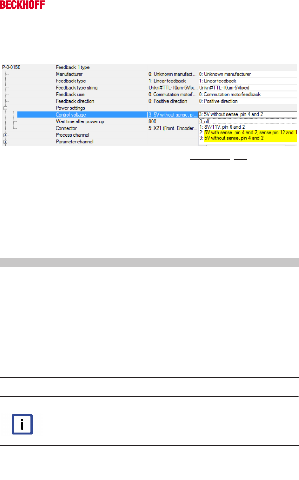
Advanced system characteristics
Servo Drives AX5000 161
Version: 2.4
If the setting is "5V", the AX5000 expects a sense line to be connected. The setting "5V fixed" must be
deselected if the encoder employed does not have a sense connection.
The selection leads to different settings in the "Power Settings" in the feedback parameter P-0-0150 (picture
below).
An incorrect selection leads to AX5000 error messages (see section “Error codes”). [}161]
Error during activation (enable) of the AX5000
If the shield of the motor cable and/or feedback cable is not connected over a large area with the housing of
the AX5000, this leads to a feedback error in the current feed to the linear motor. The position is then
correctly displayed only when pushing the motor by hand.
The shield of the motor cable is normally connected with a clip to the metal bracket of the motor connector.
The screws of the motor connector (X13/X23) must be screwed to the housing of the AX5000 and fastened
with a tightening torque of 0.6 Nm.
Error codes
Error code Error description
F152 Channel Errors
If only this error is displayed, it is probably a two-channel device and the error cause is
located in the other channel. Otherwise, observe the other error messages!
F702 Superordinate message. Please observe the other error messages!
F70E Superordinate message. Please observe the other error messages!
F707 No feedback voltage
• The power supply is not correctly connected.
• The sense line is not correctly connected.
• No sense connection exists.
FA01 Initialization error
• Incorrect setting in parameter P-0-0150.
• Wiring error
FA49 Feedback process channel error (1Vss)
The amplitude of the analog signal is too small -> check the connection.
F4A5 SoE Communication Parameter Error (see section “Error F4A5 [}162]”)
Note
Consequential error!
Please contact the Beckhoff applications department if the servo drive displays consequen-
tial errors that are not described in this section!
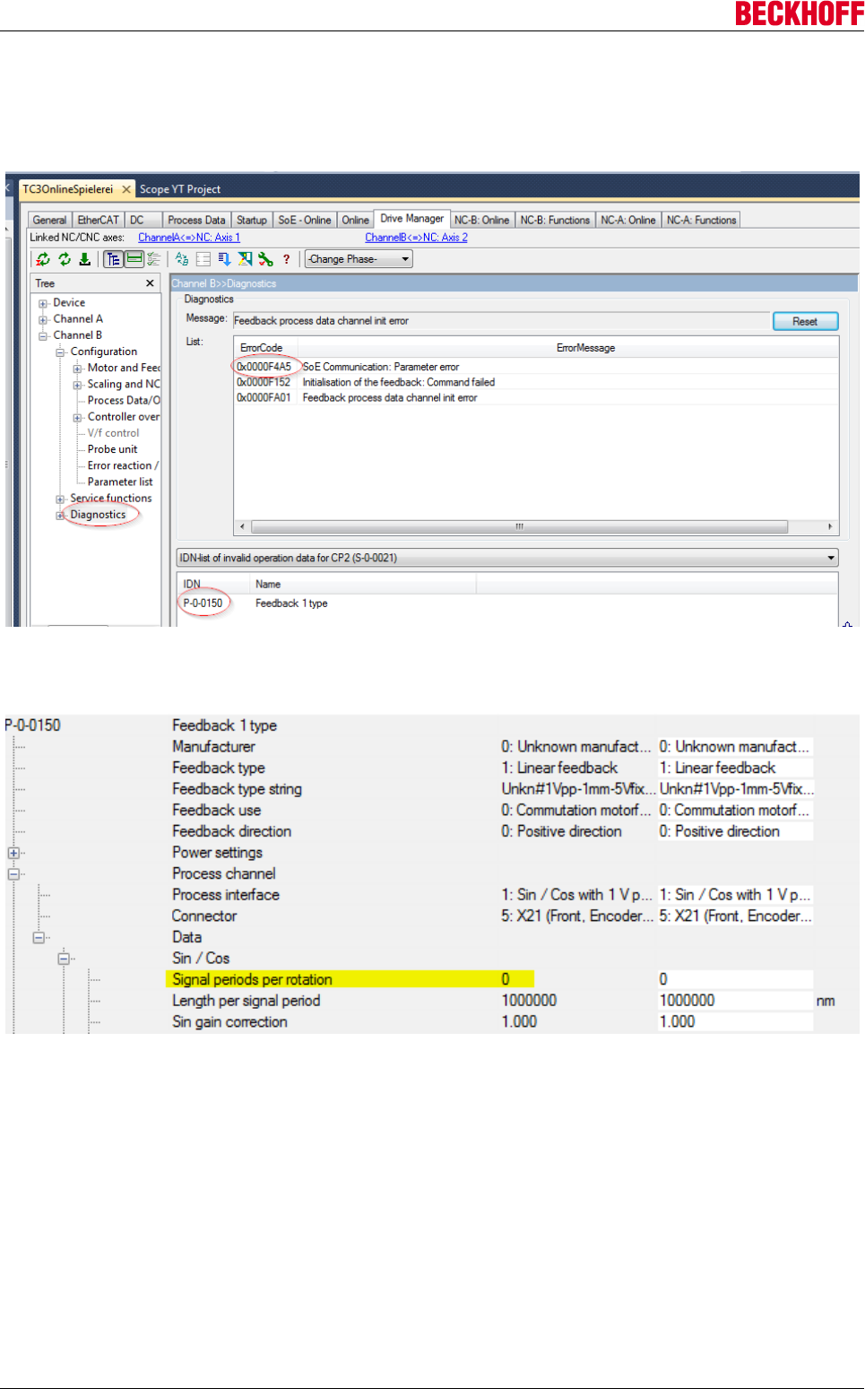
Advanced system characteristics
Servo Drives AX5000162 Version: 2.4
Error F4A5 "SoE Communication Parameter Error"
The parameter that caused error F4A5 is output in parameter S-0-0021 (picture below). This can be read in
the Diagnostics window.
In this case F152 and FA01 are consequential errors of F4A5. The cause of the error is an incorrect setting
in parameter P-0-0150.
A value > 0 must be entered for "Signal periods per rotation" (picture above). This takes place automatically
if, during the configuration, the motor is selected first and then the feedback.
The correct value is the pole pair distance / ("Length per signal period")
Sample:
Signal periods per rotation = 24mm / 1000000nm = 24
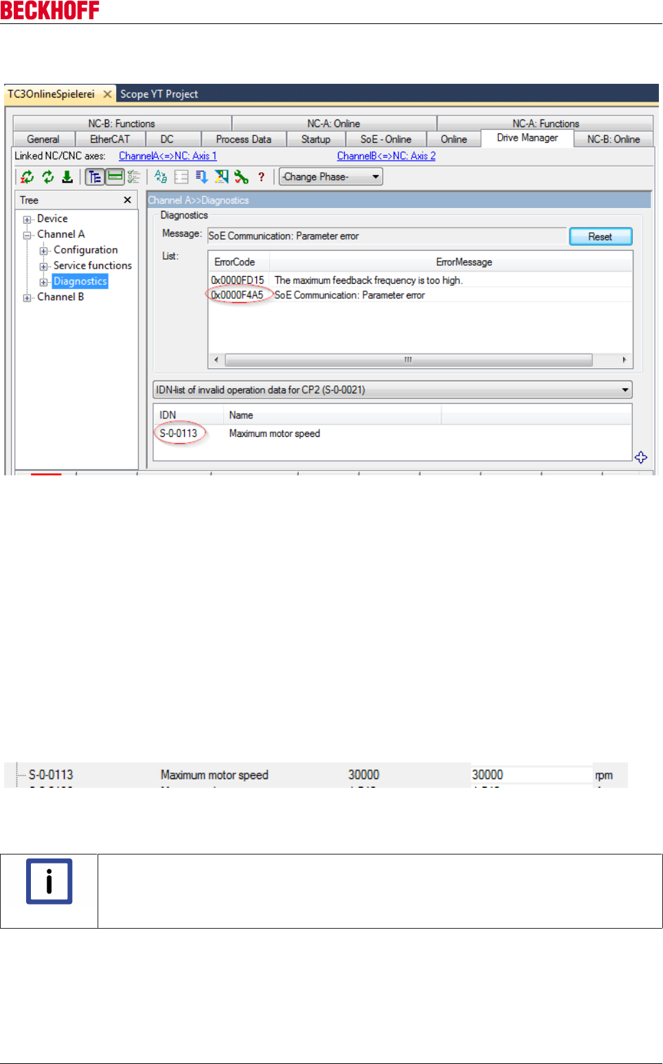
Advanced system characteristics
Servo Drives AX5000 163
Version: 2.4
The error message F4A5 can also occur with a reference to parameter S-0-0113 "Maximum motor speed":
In this case the additionally occurring error message FD15 allows a conclusion to be drawn about the cause:
the selected measuring system and the maximum velocity configured in S-0-0113 result in a too high input
frequency at the encoder input (X11/X21).
Sample:
Measuring system with 20 µm signal period. Maximum travel speed of the motor = 12 m/s.
12 m/s : 20µm = 1000000 1/s = 1 MHz
The max. permissible input frequency for sine/cosine signals at X11/X21 is 250 kHz.
Remedy: Reduce the value of S-0-0113. The maximum possible speed of the motor is required only in very
few applications.
Note: The value of the max. speed is shown in the parameter list in rpm. In the case of linear motors 1 rpm is
one pole pair distance per minute.
Conversion of the displayed value for a motor with a pole pair distance of 24 mm:
30000rpm * 0.024m / 60 = 12 m/s
Note
Further information can be found in the parameters:
S-0-0021 and P-0-0150.
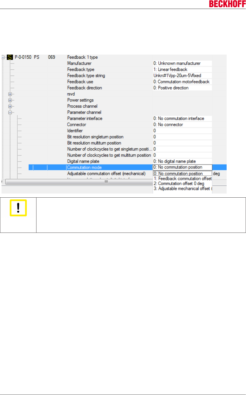
Advanced system characteristics
Servo Drives AX5000164 Version: 2.4
Error F107 "Status of the axis: current controller not ready"
If this error appears, the entry "Commutation Mode" in parameter P-0-0150 must be changed from "No
commutation" to "2:Commutation Offset 0 deg" or "3:Adjustable mechanical Offset". Refer also to section
"Determination of the commutation offset".
Attention
Nature and source of the danger
The setting "0: No commutation position" is intended to prevent an axis being inadvertently
activated and then moving in an unforeseeable manner or "running away". If not already
done, it is essential after the change to determine a valid commutation offset before the
axis is activated (enabled).
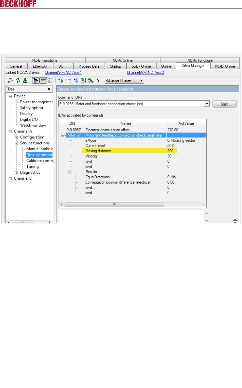
Advanced system characteristics
Servo Drives AX5000 165
Version: 2.4
Checking the motor connection and feedback
The motor can execute a defined movement independently of the feedback on the basis of command
P-0-0166. If the movement is observed (e.g. with the software oscilloscope), conclusions can be drawn
about the feedback settings.
Enter a value of 360 degrees in parameter P-0-0167 in the setting “Moving distance”. On execution of
P-0-0166 the motor is then moved by one electrical revolution. In the case of linear motors this corresponds
to one pole pair distance. Since the motor executes an undefined movement before that, it is a good idea to
record the complete movement with the software oscilloscope.
The following signals should be recorded:
• Torque Feedback (S-0-0084)
• Position feedback value 1 (S-0-0051)
• ActPos (from the NC)
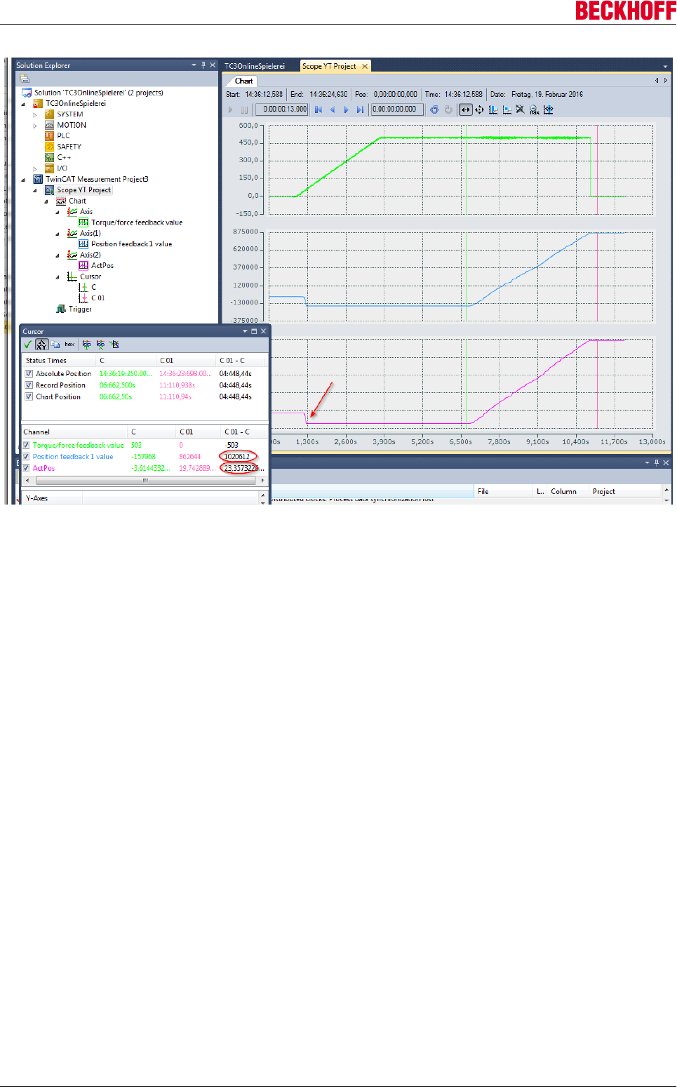
Advanced system characteristics
Servo Drives AX5000166 Version: 2.4
If the motor doesn’t move by the expected pole pair distance, check the value entered in parameter
P-0-0125 (Pole pair distance).
The jerky movement at the beginning (picture above → red arrow) is not included in the observation. The
motor aligns itself via the poles.
From the current curve it can be seen that the value initially ramps up and is then kept constant for a while.
During that time the direction is electrically turned once. The value set in parameter S-0-0051 should
increase by approx. 220 (1048576) increments. The NC position (ActPos) should increase by the value of a
pole pair distance. In the example the values are sufficiently precise with 1020612 and 23.357.
If the increase of S-0-0051 differs considerably from 220, the resolution of the linear encoder has not been
entered correctly.
If S-0-0051 proceeds correctly but ActPos displays a wrong difference, the scaling factor has been set
incorrectly.
The connection of the motor phases must be checked if the movement does not proceed evenly, but only a
jump takes place, for example.
Advanced system characteristics
Servo Drives AX5000 167
Version: 2.4
10.1.5 Third-party motors
10.1.5.1 Commutation offset for third-party motors
10.1.5.1.1 Preliminary remark
This section provides information on checking a direction of rotation and determining the commutation offset
for third-party motors.
Please observe the following notes:
A commutation offset can only be determined and stored for motors with resolver, absolute encoder (single-
or multi-turn) or the part-absolute MES.
For incremental encoders (sine/cosine or TTL signals) the “Wake&Shake” routine must be configured. This is
necessary, since in this case the commutation offset is not constant. The “Wake&Shake” routine
redetermines the commutation offset after each start.
Note
Do not use the electronic name plate!
If a motor with an EnDat or BISS encoder is used, we advise against not using an elec-
tronic name plate.
Attention
Inversion of the count direction
All direction settings must have their default values. Do not invert a count direction before
the correct commutation angle was determined!
The offset to be determined can be a mechanical offset relative to the rotor position or an electrical offset
relative to the electrical rotation. Both procedures are explained below.
Note
Further information can be obtained in the parameters:
P-0-0057, P-0-0058, P-0-0150, P-0-0160, P-0-0166, P-0-0167
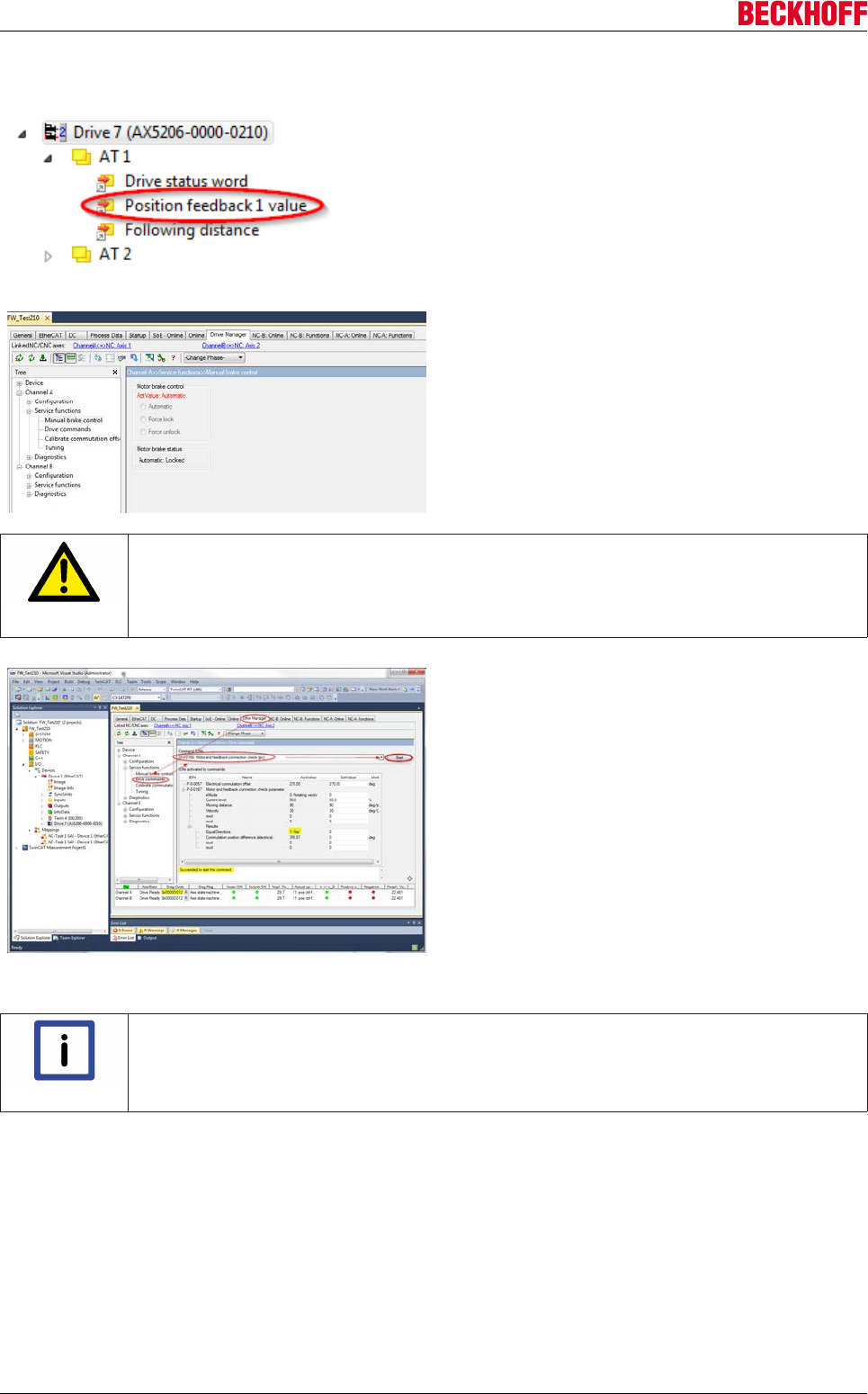
Advanced system characteristics
Servo Drives AX5000168 Version: 2.4
10.1.5.1.2 Checking the direction of rotation
Please note that for proper operation the count
direction of the feedback system must match the
sequence of the motor phases.
Turn the motor shaft clockwise, viewed from the A-
side. The parameter “Position feedback 1 value” (see
lower image) should be positive. If this is not the
case, the sine and cosine signals at the motor should
be swapped.
If the motor has a holding brake, it can be released in
the TCDriveManager under “Service functions/
Manual operation” (see lower image).
Now use the command P-0-0166 to check the
counting direction of the feedback system and
whether it matches the connection of the motor
phases.
CAUTION
Motor movement!
When you check the counting direction of the motor with the command P-0-0166, the motor
will move. Therefore, please keep a safe distance from the motor with all body parts before
you start the command P-0-0166!
The AX5000 must be set inactive without error (diag
code = 0x0000D012).
After selecting the command P-0-0166 press “Start”.
Confirm the selection (Do you really want to
continue?) with “Yes”.
The command P-0-0166 was successfully completed
when the message “Succeeded to start the
command” appears in the context menu.
The verification result can now be read in parameter
P-0-0167. If the “Equal Directions” selection area
shows 0: No, change the order of the motor phases
(The direction of rotation of the feedback system was
already checked and possibly corrected in the
previous step).
Note
Please do not use a TwinCAT setting to change the motor phases at the mo-
tor connection.
Swap motor phases U and V, for example, at the motor connector plug (X13/X23).
If the “Equal Directions” selection area now shows 1:Yes, the commutation offset can be determined based
on one of the following methods.
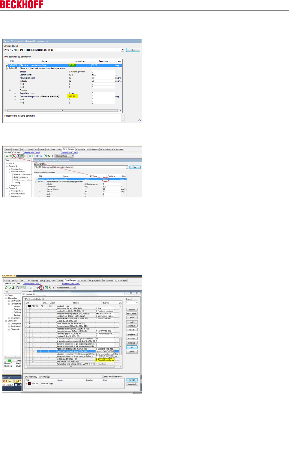
Advanced system characteristics
Servo Drives AX5000 169
Version: 2.4
10.1.5.1.3 Determining the electrical commutation offset
Execute the command P-0-0166 (see section
“Checking the direction of rotation”). To determine the
commutation offset we need the current value from
parameter P-0-0057 and the current value from
parameter P-0-0167:
Read the value for “Commutation position difference”.
Subtract this value from the value in P-0-0057
“Electrical commutation offset”. If the result is
positive, this is the new value for P-0-0057. If the
result is negative, add 360°.
Sample:
90° - 178.57° = -88.57°
-88.57° + 360° = 271° (fractions can be neglected.)
The result is the new value for P-0-0057 “Electrical
commutation offset”. Enter the value at SetValue and
confirm with <Enter>. Confirm the message that is
displayed with <Yes>.
Pressing the download button (red circle) activates
the new value immediately.
The value is displayed in the setting “ActValue” after
the download is complete. Execute command
P-0-0166 again!
The value for “Commutation position difference”
should now lie within the range: 355 … 360 = 0 … 5.
355 … 360 = 0 … 5 liegen.
If this value is displayed you have successfully
completed the commutation search! The offset value
has already been adopted into the startup list with the
download button.
To use the commutation angle, the “Commutation
mode” must be changed in parameter P-0-0150:
Change the entry “Commutation mode” to
“3:Adjustable offset”. Then reactivate the TwinCAT
configuration.
After changing the “commutation mode” once, this
method has the advantage (compared with the
mechanical offset) that the offset (P-0-0057) can be
changed at any time without having to restart the
system.
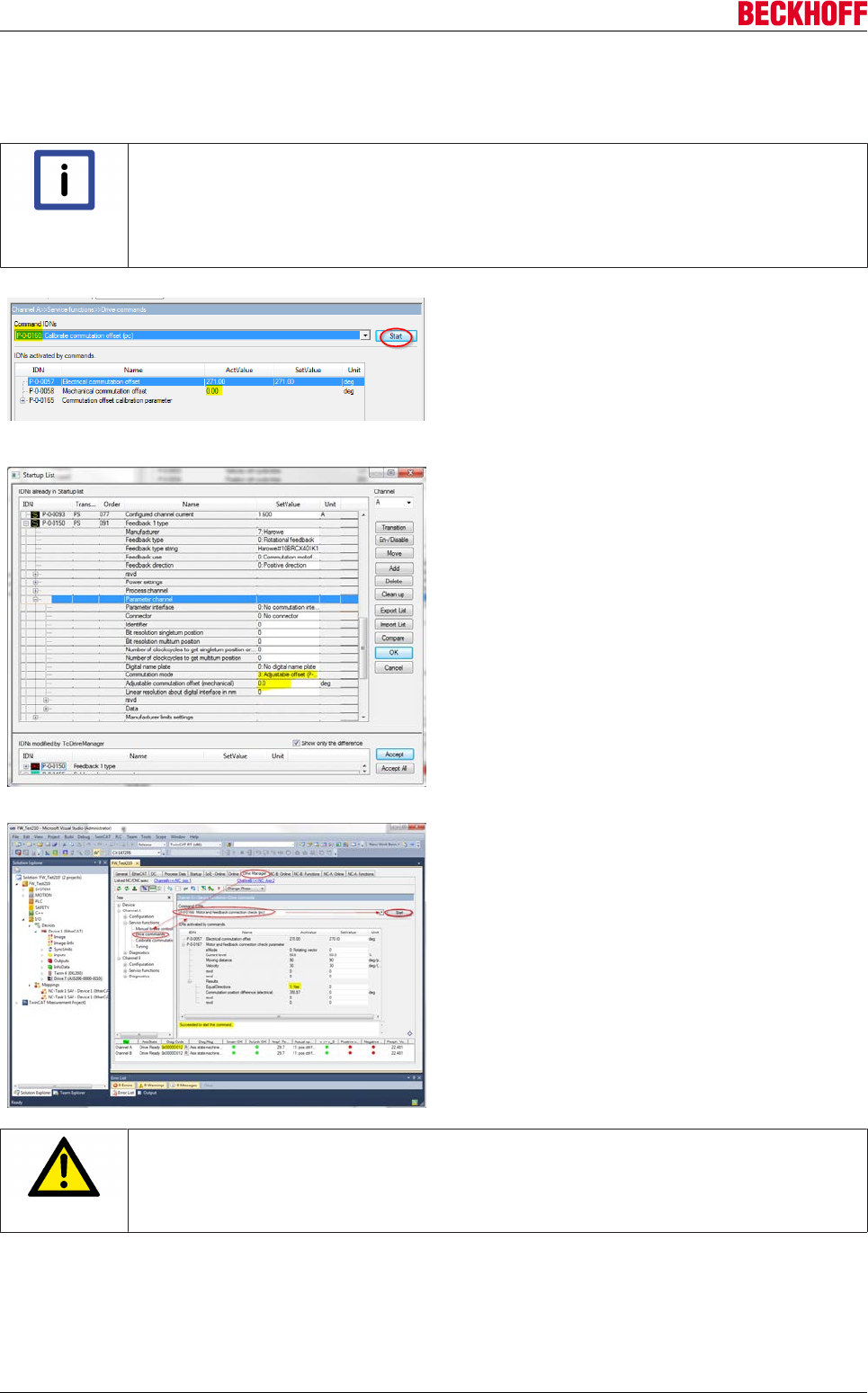
Advanced system characteristics
Servo Drives AX5000170 Version: 2.4
10.1.5.1.4 Determining the mechanical commutation offset
Abridged procedure:
Note
Adjustable commutation mechanical value!
Before determining the mechanical commutation offset, check whether the value “Ad-
justable commutation mechanical” in P-0-0-0150 is set to 0. If this is not the case, set the
value to 0 and activate the TwinCAT configuration. Then perform the steps described be-
low.
1.) Run command P-0-0166.
2.) Press the "Download" and "Start" buttons. Wait until the
"Suceeded to start the command" appears.
3.) You get a new value in parameter P-0-0058 "Mechanical com-
mutation offset". Remember this value.
4.) Open the "Startup list". Open the parameter structure P-0-0150.
Open "Parameter Channel".
5.) Set parameter P-0-0150 "Feedback 1 Type" in "Commutation
mode": 3 Adjustable offset.
6.) Change the value in P-0-0150 "Feedback 1 Type" in the "Ad-
justable commutation offset (mechanical)" to the value which you
have previously read in parameter P-0-0058.
Confirm with OK and activate the configuration in the TwinCAT
System Manager.
7.) Change to the "Drive Commands" tab and execute command
P-0-0166 "Motor and feedback connection check".
8.) Leave the default values and confirm with Start. If the message
"Suceeded to start the command" appears, open the parameter
structure of the P-0-0167 "Results".
“Equal direction" must be "Yes" and "Command position differ-
ence" must be between 355 ° and 360 "(0 ° ... 5 °).
CAUTION
Motor movement!
If you execute the command P-0-0166, the motor performs a movement. Therefore, please
keep a safe distance from the motor with all body parts before you start the command
P-0-0166!
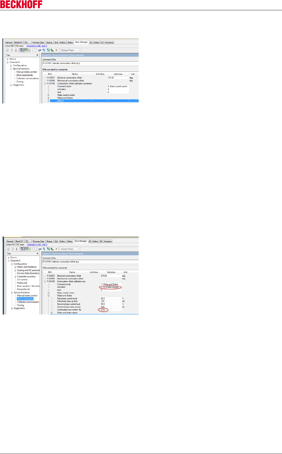
Advanced system characteristics
Servo Drives AX5000 171
Version: 2.4
10.1.5.1.5 Configuration of the Wake&Shake routine
A configuration requirement is that the count direction
of the feedback system matches the sequence of the
motor phases.
Details of the process for finding the commutation
with “Wake&Shake” can be found in the Beckhoff
Information System under the keyword: "Electronic
commutation".
This section only contains a brief overview.
The command P-0-0160 executes the routine. The
type of execution can be set in parameter P-0-0165.
For “Command mode” you can select between: Static current vector and Wake and Shake.
• 0:
• 1:
auswählen.
The “Static current vector” procedure results in a larger motor movement. It can be used for testing.
The “Wake and Shake” procedure minimizes the axis movement. This procedure is the one that tends to be
used in practice.
Both procedures determine a commutation offset, although this is not shown in parameter P-0-0058. This is
due to the fact that a new value has to be determined at each restart. This value depends on the axis
position. The numerical value is therefore meaningless for the user.
The result can then be checked with the command P-0-0166. Both procedures should initially be performed
with the default values.
The setting “Activation 1: On enable request” has the
effect that the AX5000 automatically executes a
commutation search with the first enable after a
restart.
With "Wake and Shake" it often makes sense to set
"Commutation pos control: Kp 0", in order to avoid
execution errors.
10.1.6 Homing
10.1.6.1 Homing
Homing refers to an axis initialization run during which the correct actual position is determined by means of
a reference signal. This procedure is referred to as homing, referencing or calibration. A switch that is
triggered at a known, unique position along the travel path serves as reference signal. Further signals such
as the encoder zero track can be analyzed in order to increase the precision.
In general a distinction is made between drive-controlled homing and NC-controlled homing. Drive-controlled
homing is carried out automatically by a suitable drive without input from the control system and is not
discussed in detail in this documentation. NC-controlled homing is fully controlled by the control system and
supports a wide range of drive types. The different NC-controlled homing mechanisms are described below.

Advanced system characteristics
Servo Drives AX5000172 Version: 2.4
Position reference systems and encoder systems
A distinction is made between different position reference systems (measurement systems), depending on
which position measuring system is used. An absolute measurement system provides an absolute position
(directly after switching on) that is unique over the whole travel path. Such a measurement system is
calibrated once and set via a persistently stored position offset. In this case homing is not required even after
a system restart. In contrast, relative measurement systems provide a non-unambiguous position value (after
switching on) that must be calibrated through homing. Relative measurement systems are subdivided further
into purely relative systems (incremental encoders) and part-absolute systems, which only provide a unique
position during a motor or encoder revolution.
• Absolute position - e.g. multi-turn encoder
◦ BiSS
◦ EnDat
◦ Hiperface
◦ SSI
• Part-absolute position - e.g. single-turn encoder
◦ BiSS
◦ EnDat
◦ Hiperface
◦ MES (Beckhoff)
◦ Resolver
• Relative position - incremental encoders
◦ Sine / cosine (sine 1 Vss)
◦ HTL (rectangle)
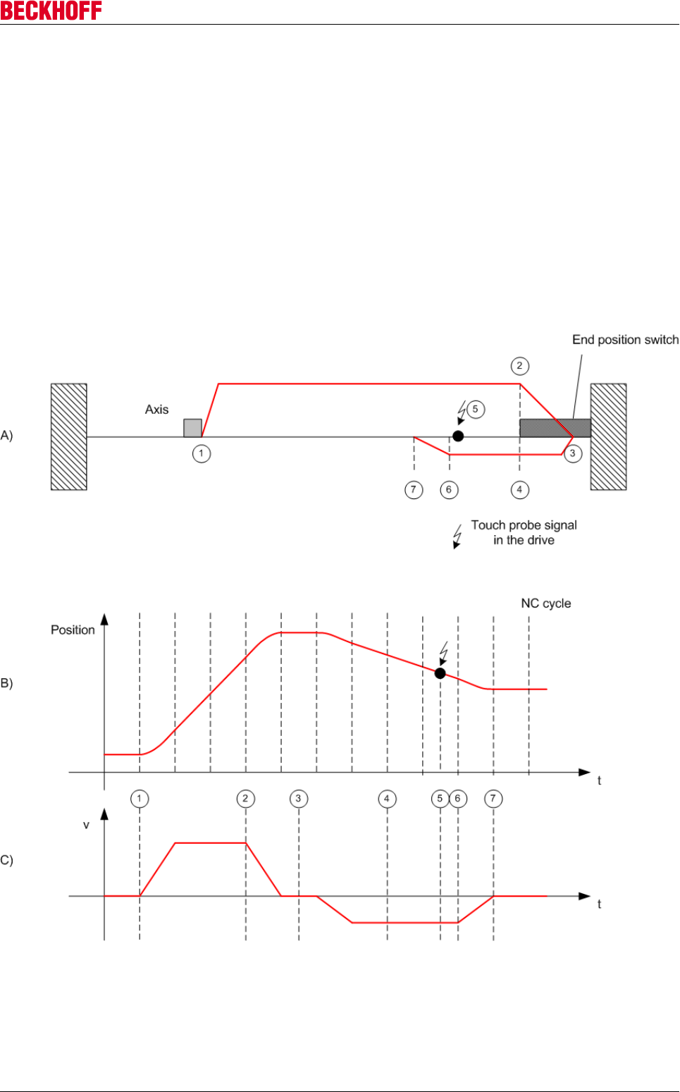
Advanced system characteristics
Servo Drives AX5000 173
Version: 2.4
General description of a homing procedure
Figure A shows a schematic diagram of a homing procedure with individual velocity profile phases.
1. When the machine is switched on the axis is in a random position (1).
2. Homing is initiated, and the axis travels towards the reference cam.
3. Once the reference cam is detected, the axis stops and reverses.
4. The axis moves away from the reference cam and detects the falling edge of the reference cam sig-
nal.
5. The axis continues and searches for a sync pulse or another distinctive event, depending on the refer-
ence mode setting. This step may be omitted where appropriate.
6. The occasion is detected and the specified reference position is set.
7. The axis stops and thus stands slightly away from the reference position. The reference position was
set a short while before with maximum accuracy.
Figures B and C show the position and velocity profile during homing.

Advanced system characteristics
Servo Drives AX5000174 Version: 2.4
Referencing modes
The NC system supports different referencing modes, depending on the encoder system type.
•Homing based on reference cam (Plc Cam)
The simplest axis referencing mode uses a reference cam that generates a digital signal at a defined
position along the travel path. During homing the NC determines the signal edge and allocates a
configurable reference position to this position. Referencing based on a reference cam is always
possible, irrespective of the encoder type, and is a prerequisite for other, more precise modes.
•Software Sync
Software Sync mode enhances the homing precision by additionally detecting the encoder count
overflow after an encoder or motor revolution, after the reference cam signal has been detected. This
mode requires a part-absolute encoder (e.g. resolver) with constant overflow interval relative to the
reference cam. Overflow detection is parameterized via the Reference Mask parameter (see System
Manager section).
•Hardware Sync
Some encoder systems provide a sync pulse per revolution (zero track) in addition to the count. The
homing precision can be enhanced by selecting this mode, if the encoder evaluation logic is able to
pick up the sync pulse. The precision is comparable with Software Sync. Hardware Sync mode may
require parameterization or special wiring of the drive or encoder system.
•Hardware Latch
Hardware Latch reference mode (Hardware Latch Pos or Hardware Latch Neg, depending on edge)
requires an external digital latch signal for storing the encoder position in the evaluation unit of the
encoder system. The encoder system must support such a latch function and may have to be
configured first in order to be able to utilize this function.
Absolute encoder system Part-absolute encoder sys-
tem
Relative encoder system
NC Referencing not required Recommended reference
mode SoftwareSync
(also possible: PlcCam,
HardwareSync)
Recommended reference
mode HardwareSync
(also possible: PlcCam)
Drive Referencing not required Drive setting not required Drive parameterization
required
(for Sercos/SoE see Probe
Unit)
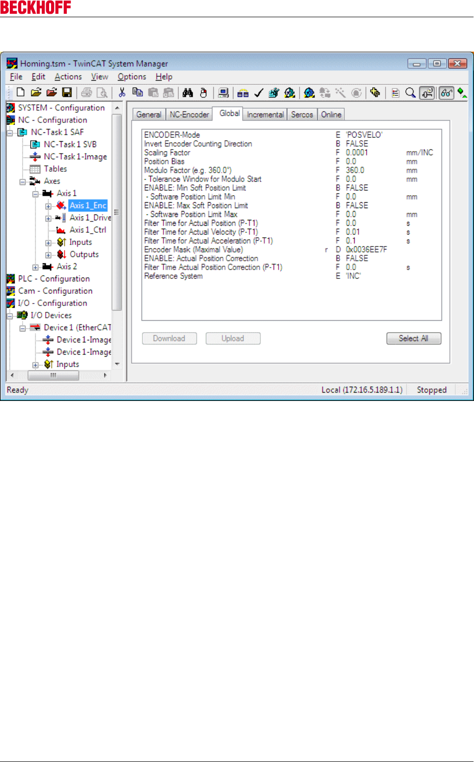
Advanced system characteristics
Servo Drives AX5000 175
Version: 2.4
Parameterization in the System Manager
Reference System : The encoder parameters Reference System determines whether the encoder system
used is incremental or absolute. In an absolute encoder system the encoder value is taken from the control
system without modification.
Not all NC encoders support this optional parameter, i.e. only those types that offer a choice between
absolute and incremental encoder reference system (measurement system) support it (e.g. SERCOS,
KL5001, M3000, ProfiDrive, Universal). This choice determines whether the actual encoder position is
interpreted and evaluated as an absolute or incremental position, based on an absolute or incremental
reference system (measurement system).
In an absolute reference system no further processing takes place with regard to encoder counter value
overflow or underflow. It is assumed that the counter value is unique within the axis traversing range and no
encoder counter value overflow or underflow occurs. Otherwise there would be a discontinuity in the actual
position, resulting in a position following error. Axis referencing via MC_Home is not possible. Instead, the
actual position is calibrated once via the parameter Position Bias (zero offset / position offset).
In an incremental reference system axis referencing via MC-Home is generally required. In addition the NC
automatically detects and accounts for encoder counter value overflow or underflow events, so that
continuous axis operation is possible over many months ("infinite range").
Encoder Mask (maximamum value): The encoder mask determines the bit width for the incremental
encoder position. The encoder mask is used for detecting and counting in range overflow events.
Scaling Factor: The scaling factor is multiplied by the incremental encoder position, including all overflows.
From this an absolute axis position can be calculated with the parameterized physical unit.
Position Bias (zero offset): Position offset; moves the axis coordinate system relative to the encoder
coordinate system. This value is mainly used in absolute encoder systems. In relative systems an offset is
usually not required, since the system moves to a parameterized reference position after homing.
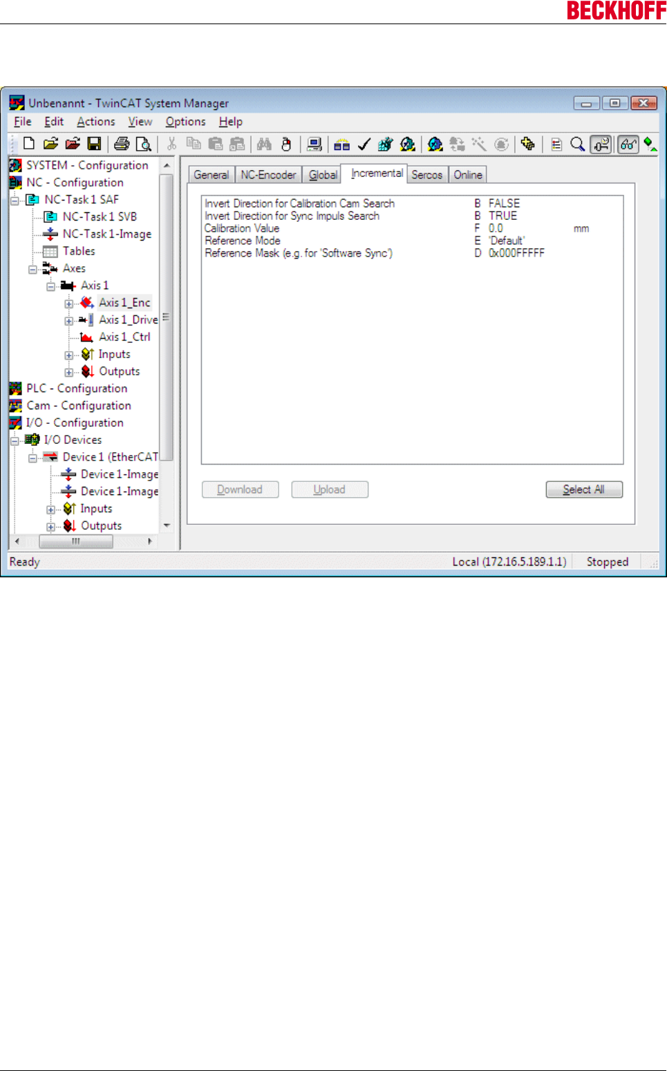
Advanced system characteristics
Servo Drives AX5000176 Version: 2.4
Invert Encoder Counting Direction: The encoder count direction can be inverted if it does not match the
required logical count and travel direction.
Reference Mode : Referencing mode as described above (Plc CAM, Hardware Sync, Hardware Latch Pos,
Hardware Latch Neg, Software Sync). The default mode corresponds to Plc CAM mode.
The Reference Mode parameter is used to specify the type of reference event (physical or logical event) for
the referencing process. Depending on the parameterized reference mode, during the referencing procedure
either the hardware property of the drive or encoder (e.g. hardware latch) is used, or the reference event is
exclusively detected within the control, i.e. without further hardware reference.
Reference Mask: The reference mask parameterizes overflow detection for Software Sync reference mode.
It is less or equal the encoder mask and defines an encoder value range, which is part-absolute. Examples
include the bit width of a motor revolution or the bit width of a sine period in a sine/cosine encoder. Software
Sync therefore always detects the same overflow position in a part-absolute encoder system.
Calibration Value: Reference position to which the axis position is set after homing.
Invert Direction for Calibration Cam Search: The parameter inverts the axis travel direction for searching
the referencing cam during homing. The standard direction is negative, i.e. towards the axis coordinate
system origin.
Invert Direction for Sync Impuls Search: The parameter inverts the axis travel direction for searching the
sync pulse during homing.
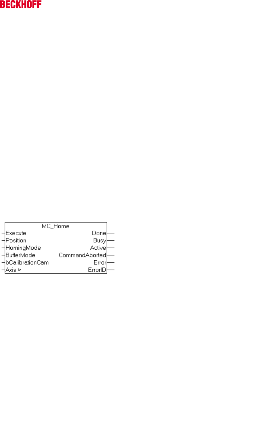
Advanced system characteristics
Servo Drives AX5000 177
Version: 2.4
Referencing of coupled axes
TwinCAT enables axis coupling during referencing. The coupled axes do not necessarily have to be
referenced. Axis coupling enables referencing of gantry axes, for example, provided the system can ensure
that the two axes are suitably oriented relative to each another before homing. In this case the procedure is
as follows:
• Ensure that both axes can be moved in coupled mode. (Position comparison is not possible at this
stage, because none of the axes is referenced.)
• Couple axis 2 with axis 1.
• Start homing for axis 1. Slave axis 2 will travel with axis 2.
• Decouple the axes after the homing procedure.
• Couple axis 1 with axis 2.
• Start homing for axis 2. Slave axis 1 will travel with axis 2.
• Decouple the axes after the second homing procedure.
• Move both axes to a set position for alignment. The travel path for both axes should be minimal and
may correspond to the mean value from both positions, for example.
• Couple the axes. The coupled system is now referenced.
Programming a homing procedure in the PLC
MC_Home
The MC_Home function block is used to initiate homing from the PLC. The reference mode and further
parameters are configured in the System Manager as described above. Only the reference cam signal
(bCalibrationCam) is fed into the block.
Drive types and I/O interface
Homing is largely independent of the drive types used. In some cases the drive has to be parameterized,
particularly if a drive latch function is used. The following chapter describes the version with the AX5000.

Advanced system characteristics
Servo Drives AX5000178 Version: 2.4
10.1.6.2 Special characteristics in hardware end positions
If a SERCOS or SoE drive (e.g. AX50xx) is in a hardware end position (positive or negative), the drive blocks
further traversing commands in end position direction and beyond the end position (see also bit 3, drive
follows command value, in the SERCOS status word), and is therefore no longer operational from a control
system perspective. This means that, without special measures, the axis can often no longer be moved from
the end position into the valid traversing range via TwinCAT or the control system. This situation is
particularly likely to occur with drives in the velocity interface, because in this case the position control leads
to frequent changes in direction in the drive velocity output.
In order to rectify this special situation, a control bit in the PlcToNc axis interface (see bit 8 called
AcceptBlockedDriveSignal in nDeCtrlDWord) can be used to force TwinCAT to accept the AX50xx axis as
operational and therefore enable a move from the end position into the valid traversing range.
In the past, in many cases the only alternative was to mechanically move the axis away from the end
position.
NC interface
PlcToNc axis interface, bit 8 called AcceptBlockedDriveSignal in nDeCtrlDWord
PLC interface
TcNc-Lib, see PLC function AxisSetAcceptBlockedDriveSignal in the TwinCAT PLC Library NC.
Homing with latch function
During homing a trigger event is expected and a position value is latched, depending on the referencing
mode (hardware latch). Parameterization is required in order to be able to use the drive latch function (see
AX5000 Probe Unit).

Advanced system characteristics
Servo Drives AX5000 179
Version: 2.4
10.1.6.3 Probe Unit
Note
Detailed method for configuration of the probe unit:
For further information of the probe unit, please look at the functional manual of the servo
drive AX5000: Probe unit function
10.1.7 Error messages during commissioning
The greatest likelihood of error messages occurs during the commissioning process. Incorrectly assembled
cables, missing shield connection, wrongly parameterized motors / feedback systems, mechanical problems
and many other issues are detected at this stage. The drive can often not be started or stops after a short
time with a diagnostic message.
Note
Documentation of all error messages
If an error message occurs, first of all please refer to the error message information in the
documentation "AX5000_DiagMessages". You will usually find suggestions for solutions
there which can be implemented relatively easily.
10.1.7.1 FA49, Feedback process channel error (1Vss)
When this diagnostic message appears it may indicate an error in the analog signal for the feedback system
(1Vss). The AX5000 monitors the output signals from the sin/cos 1Vss feedback system and switches off the
drive when the signal lies outside the tolerance range between 0.53 Vss and 1.34 Vss. The feedback
systems are specified in such a way that they only supply exact values within the stated tolerance range.
Beyond this the values may be usable but are not necessarily so.
Voltage analysis
With an external oscilloscope
The values from the feedback system can be determined with the aid of an external oscilloscope (scope).
You can connect an external scope between the feedback connector and the AX5000 and determine the
sine and cosine voltages.
With the TwinCAT software oscilloscope
Parameterization of the IDNs P-0-0150 / P-0-0180
Note
Feedback system 1 or 2
The diagnostic message FA49 applies to both feedback systems 1 and 2. You can find out
which feedback system is currently affected by pointing the mouse cursor at the diagnostic
message in the TCDriveManager. A tool tip will then appear showing the faulty feedback
system. The IDN P-0-0150 described below applies to feedback system 1. The IDN
P-0-0180 applies to feedback system 2 and has the same structure as P-0-0150.
Open the System Manager and select the servo drive (1) which is generating the error. Open the
TCDriveManager (2) and select the faulty feedback (4) in the affected channel (3). In the IDN "P-0-0150" (5)
under the "Sin / Cos" parameter (6) open the value range (8) under the Parameter "SinCos 1Vss monitoring".
Four options appear.
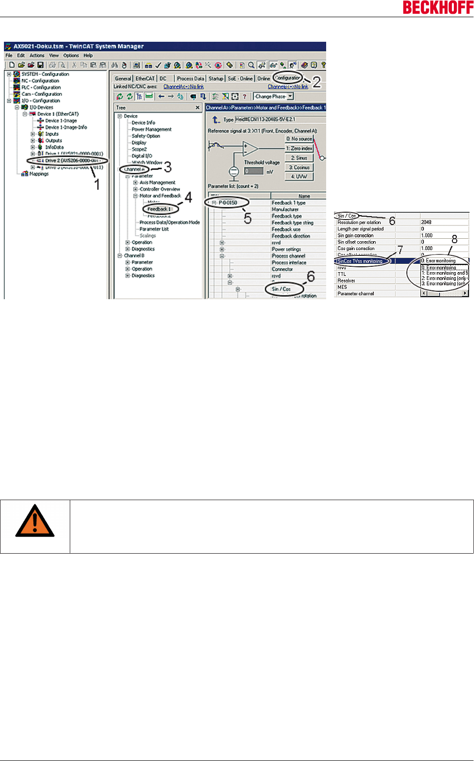
Advanced system characteristics
Servo Drives AX5000180 Version: 2.4
0 = Error monitoring (full error monitoring)
1 = Error monitoring and Sin/Cos logging (full error monitoring and logging of sin/cos signals)
2 = Error monitoring (only wire break detection) and Sin/Cos logging (only wire break detection and logging
of sin/cos signals)
3 = Error monitoring (only wire break detection)
To log the Sin/Cos signals, select either 1 or 2.
Whether to select option 1 or 2 should generally be decided depending on the application. However, there
are two rough indications for making the choice:
If the faulty axis can no longer be used because the error always occurs immediately, then you need to
select the "2 = (only wire break detection and logging of sin/cos values)" option so that the error can occur
and be logged.
If the faulty axis can be operated because the error only occurs sporadically, then you can select "1 = (full
error monitoring and logging of sin/cos values)" or "2 = (only wire break detection and logging of sin/cos
values)" so that the error can always be logged.
WARNING
Warning, risk of injury from uncontrolled movements!
If a faulty axis is used then this axis may make uncontrolled movements. Make sure that no
one is in the machine's traversing range.
In many cases the faulty axis can also be moved manually and this option should be used preferentially for
safety reasons.
Adding the debug pointer to the Startup list
In order for the sin/cos signals to be logged, the relevant debug pointers must be added to the AX5000
Startup list. Call the Startup list in the TCDriveManager using the button (9) and click on "Add" (10). A
window opens with a list of parameters including P-0-1006 to P-0-1010 (11).
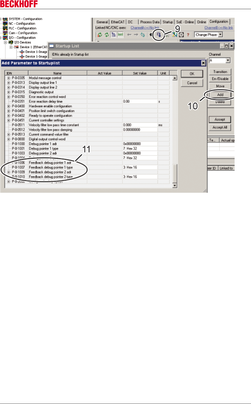
Advanced system characteristics
Servo Drives AX5000 181
Version: 2.4
The IDNs need to be parameterized before being added to the Startup list. The IDNs P-0-1006 and P-0-1007
denote sine signals, the IDNs P-0-1009 and P-0-1010 cosine signals; the structures are the same for sines
and cosines.
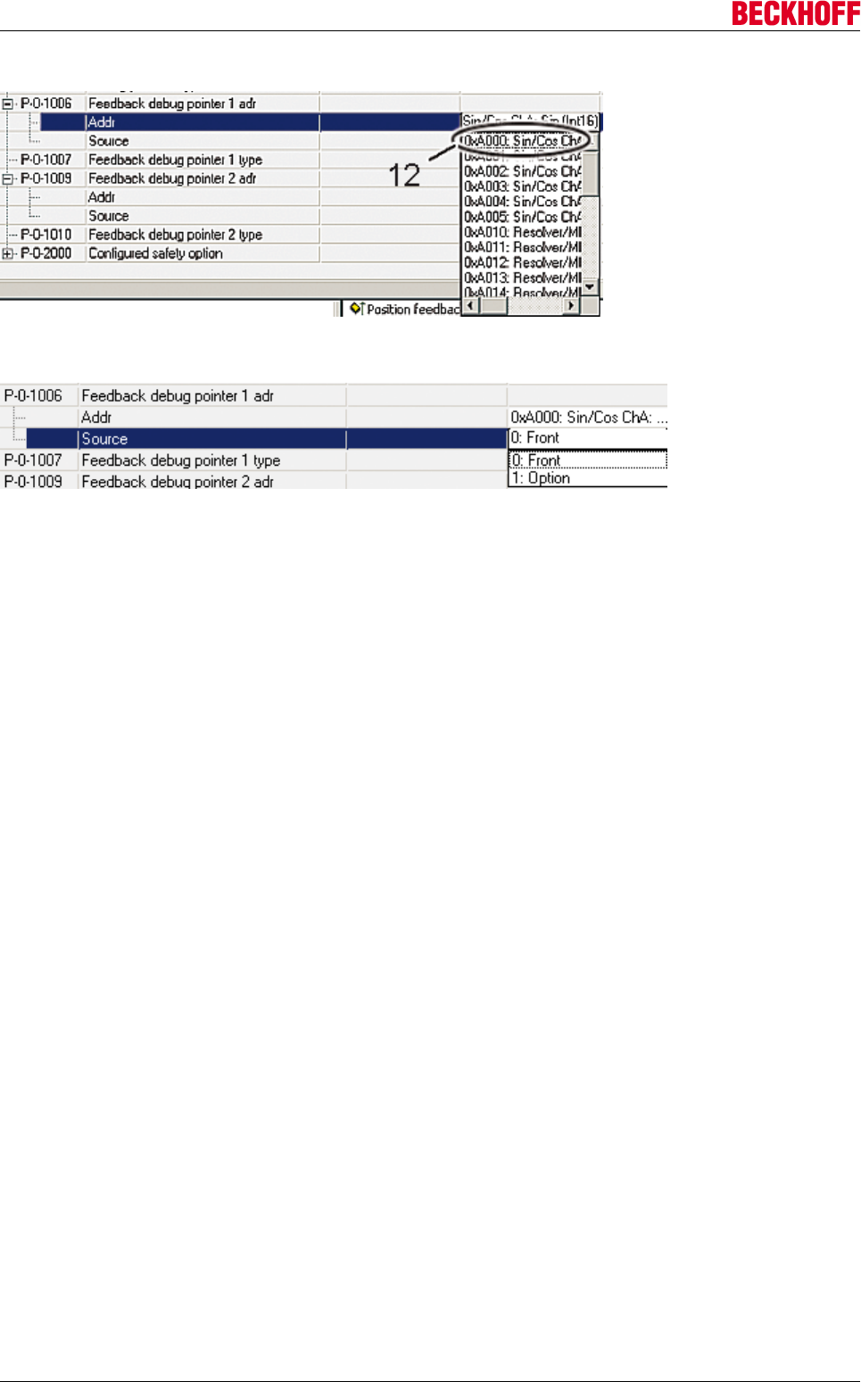
Advanced system characteristics
Servo Drives AX5000182 Version: 2.4
For the IDN "P-0-1006" under "Addr" select the address "0xA000 Sin/Cos ChA: Sin (Int16)" (12).
Under "Source" select the faulty feedback system, where "0: Front" refers to the feedback system on the
front of the AX5000 and "1: Option" refers to the feedback system on the AX5701 / 02 option card.
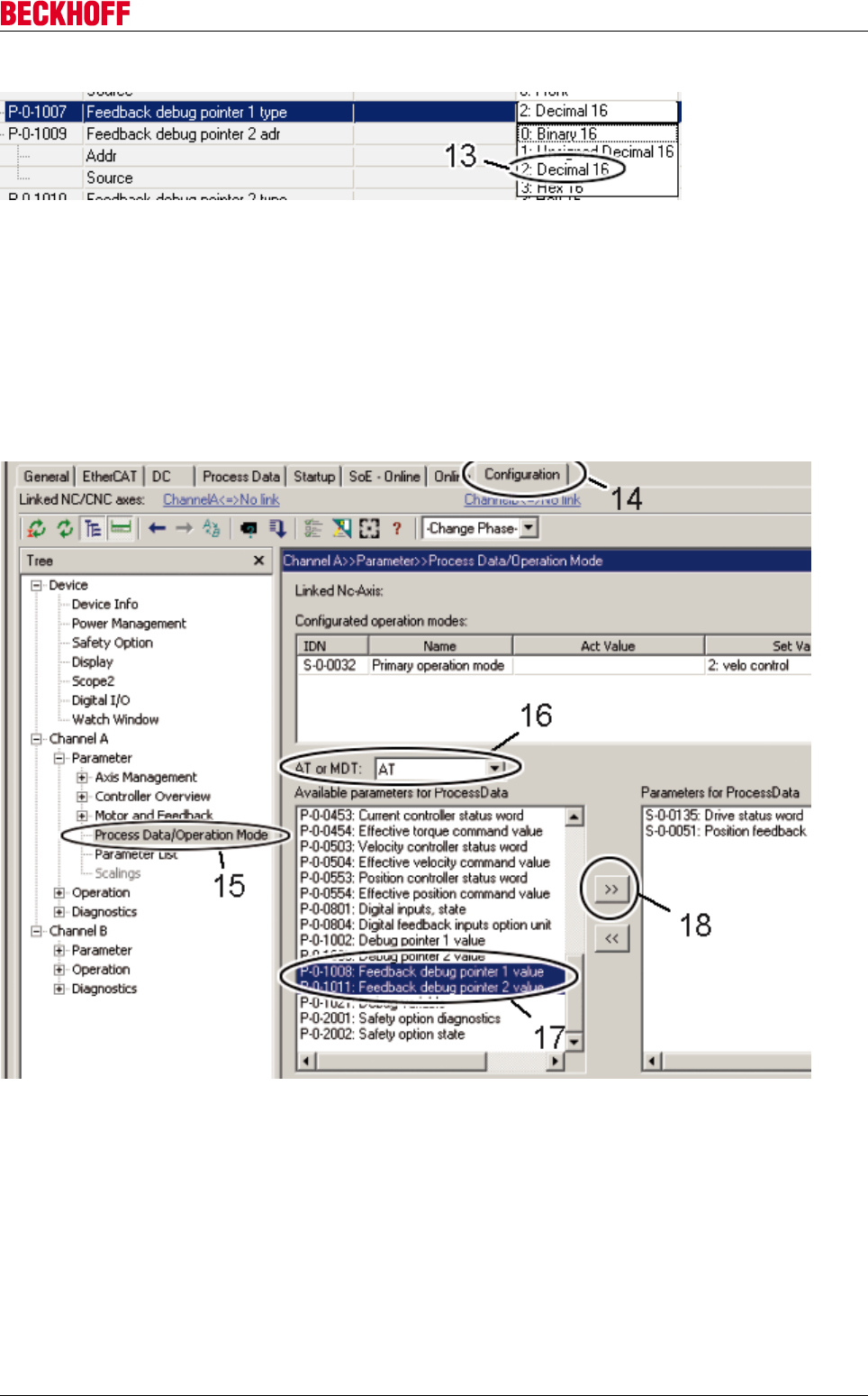
Advanced system characteristics
Servo Drives AX5000 183
Version: 2.4
For the IDN "P-0-1007" select the option "2: Decimal 16".
You now need to repeat the procedure with the IDNs "P-0-1009" and "P-0-1010". For the IDN "P-0-1009"
under "Addr" enter the value "0xA001: Sin/Cos ChA: Cos (Int16)".
Select the four IDNs and press "OK" so that the IDNs are entered in the Startup list.
Activate configuration
In the TCDriveManager (14), click in the tree on "Process Data/Operation Mode". A new window opens
where, under "AT or MDT", you select "AT" (16). Next highlight the two IDNs "P-0-1008" and "P-0-1011" (17)
and move them into the "Parameter for Process Data" window by clicking on the ">>" button (18).
Under the relevant EtherCAT Device (19), activate the ADS Server (20). Now check the boxes beside
"Enable ADS Server" and "Create symbols" (21). The "Port" (22) is entered automatically.
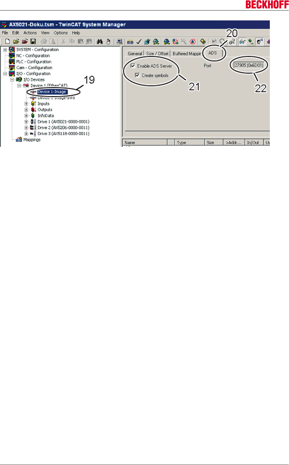
Advanced system characteristics
Servo Drives AX5000184 Version: 2.4
Start "TwinCAT Scope2" and check whether the amplitude values are permissible. The scaling factor is 1 /
46602.
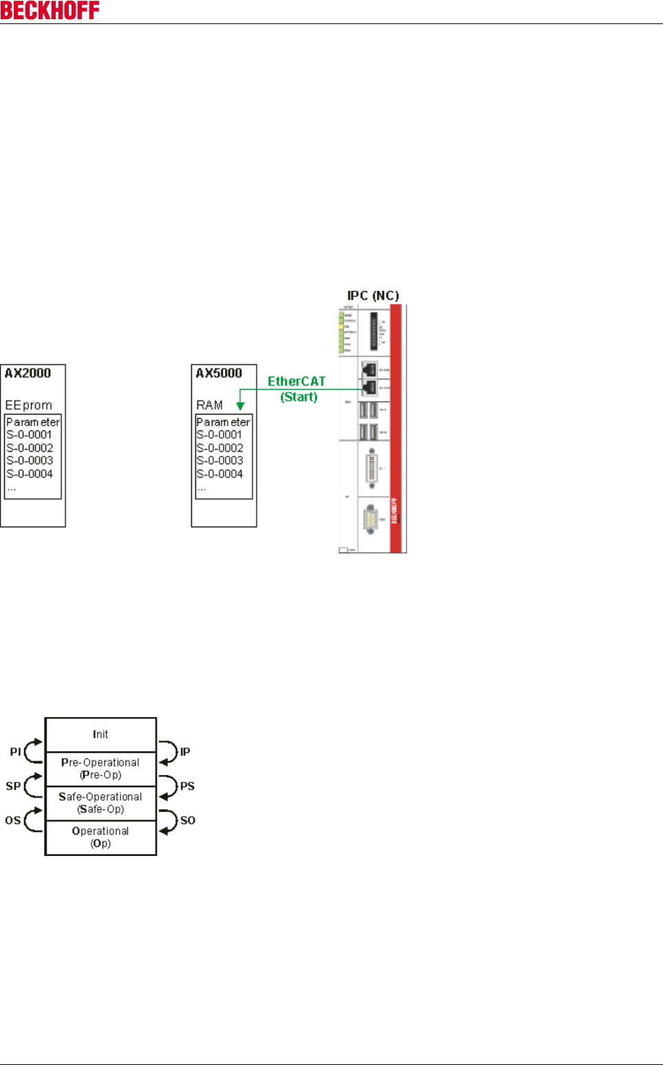
Advanced system characteristics
Servo Drives AX5000 185
Version: 2.4
10.2 EtherCAT
10.2.1 Parameter handling
The servo drives from the AX5000 series use a new method for managing their configuration parameters
(IDNs).
In contrast to conventional servo drives (e.g. AX2000), these parameters are not stored in a non-volatile
manner on the AX5000 itself, but they are transferred from the controller to the drive whenever the EtherCAT
fieldbus system starts up. This approach has the advantage that the parameter management takes place
exclusively in the corresponding TwinCAT project, without the need for separate data backup of drive
parameters. If a replacement is required, it is sufficient to replace the servo drive. There is no need to load
parameters onto the servo drive.
The parameters are transferred from the controller to the servo drive when the EtherCAT system starts up.
Due to the high data transfer rate offered by EtherCAT this process is very fast, even in larger systems.
Transitions
During startup the EtherCAT system passes through the following states: Init, Pre-Operational, Safe-
Operational, and Operational (see chapter EtherCAT state machine).
The diagram shows the following transitions:
IP: Transition from Init to Pre-Operational
PS: Transition from Pre-Operational to Safe-Operational
SO: Transition from Safe-Operational to Operational
OS: Transition from Operational to Safe-Operational
SP: Transition from Safe-Operational to Pre-Operational
PI: Transition from Pre-Operational to Init
In practice the parameters (IDNs) are transferred from the higher-level control system to the AX5000 during
transitions IP, PS and SO.
The TwinCAT System Manager indicates at which transition the individual AX5000 parameters can be
transferred.
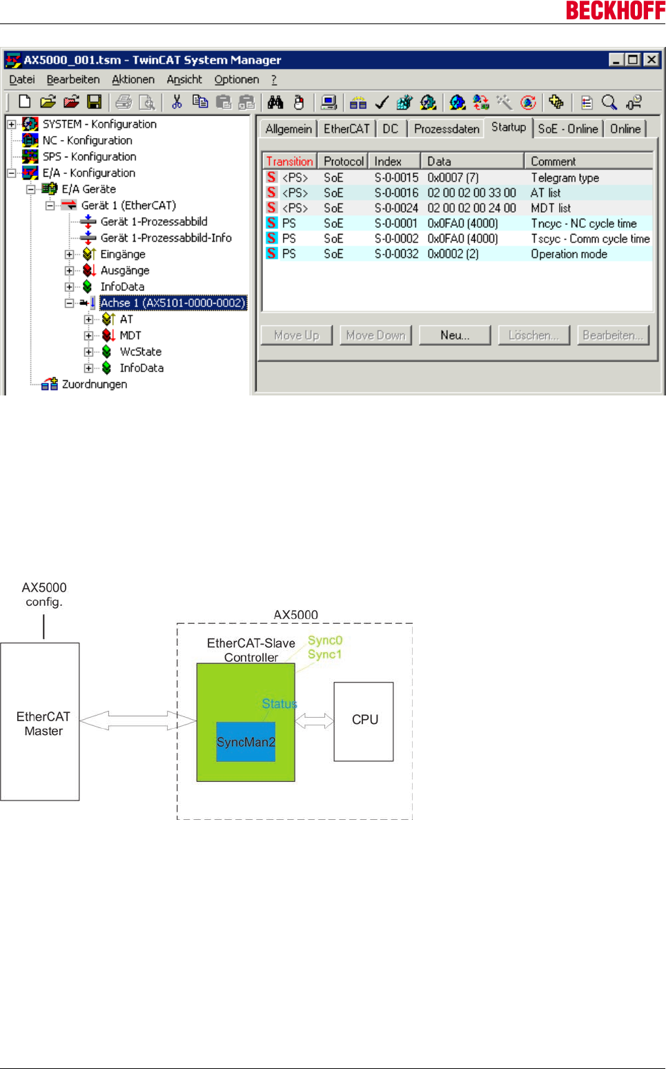
Advanced system characteristics
Servo Drives AX5000186 Version: 2.4
10.2.2 EtherCAT synchronization
The EtherCAT master sends EtherCAT telegrams to all connected EtherCAT slaves. In each slave an
EtherCAT slave controller (ESC) is implemented. In order to achieve high positioning precision and meet
stringent demands in terms of concentricity characteristics, it is necessary for the set value generation in the
master and all connected drives to be synchronized. In the EtherCAT system the so-called distributed clocks
are available for this synchronization task. For details see www.ethercat.org. The following description deals
exclusively with the synchronization of the data.
EtherCAT Master
From the TwinCAT project and the ESI files (EtherCAT slave information) of the connected slaves, the
System Manager determines the required parameterization for the distributed clocks of the connected
EtherCAT slaves when the configuration is generated. This parameterization is transferred to the slaves or
their slave controllers via Init commands whenever the EtherCAT segment starts up. Manual adjustment is
not required and should only be carried out in consultation with AX5000 support.

Advanced system characteristics
Servo Drives AX5000 187
Version: 2.4
EtherCAT slave controller (ESC)
The EtherCAT slave controller (ESC) of the AX5000 is parameterized by the master such that two
synchronization signals (Sync0 and Sync1) are generated. These signals are analyzed by the CPU and then
synchronized with the internal control algorithms.
Sync0
The "Sync0" signals are sent every 250 µs as standard. If a signal fails to materialize, the CPU generates the
error code F414, and the axes of the servo drive are stopped with the "EStop ramp".
Additional error messages:
The Sync0 cycle time may only be configured with 62.5 µs, 125 µs or 250 µs, otherwise the CPU generates
the error code F409.
If the signal "Sync0" is not activated in the ESC, the CPU generates the error code F410.
If the pulse length of the signal no longer conforms to the standard, the CPU generates the error code F411.
In the case of each error message the axes are brought to a standstill with the "EStop ramp".
Sync1
The "Sync1" signals are parameterized according to the NC cycle time as standard. This cycle time is always
a multiple of Sync0. If a signal fails to materialize (see F1), the CPU also generates the error code F414, and
the connected axes are stopped with the "EStop ramp".
Additional error messages:
The Sync1 cycle time must be a multiple of the Sync0 cycle time and must be identical to the parameters
"S-0-0001 and S-0-0002", otherwise the CPU generates the error code F412.
If the signal "Sync1" is not activated in the ESC, the CPU generates the error code F413.
If the pulse length of the interrupt no longer conforms to the standard, the CPU generates the error code
F411.
In the case of each error message the connected axes are brought to a standstill with the "EStop ramp".
End of telegram (EOT)
The EtherCAT state controller (ESC) in the slave processes the EtherCAT telegrams dynamically. At the end
of the telegram (EOT) it transfers the content to the addressed Sync Manager (if the telegram was intended
for this slave and no CRC error is present). The EOT thus lags slightly behind the signal of Sync1 by the time
DT2; the status of SyncManager2 is subsequently set to "SyncManager written". The CPU only copies the
data from SincManager2 into its own memory area if this status is "SyncManager written" at the time of
Sync1. At the time of the Sync1 signal, the CPU expects a written SyncManager2. The end of the telegram
must therefore occur just before the Sync1 signal is generated. The data are not copied if the status is not
"SyncMan written"; if the data cannot be copied twice in succession, the CPU generates the error code F415
and the connected axes are brought to a standstill with the "EStop ramp".
Note
Jitter!
The tolerance for the existence of new data at the right time, due to "jitter" etc., is NULL.
The EtherCAT master must ensure that the data arrive at the SyncMan2 in time.
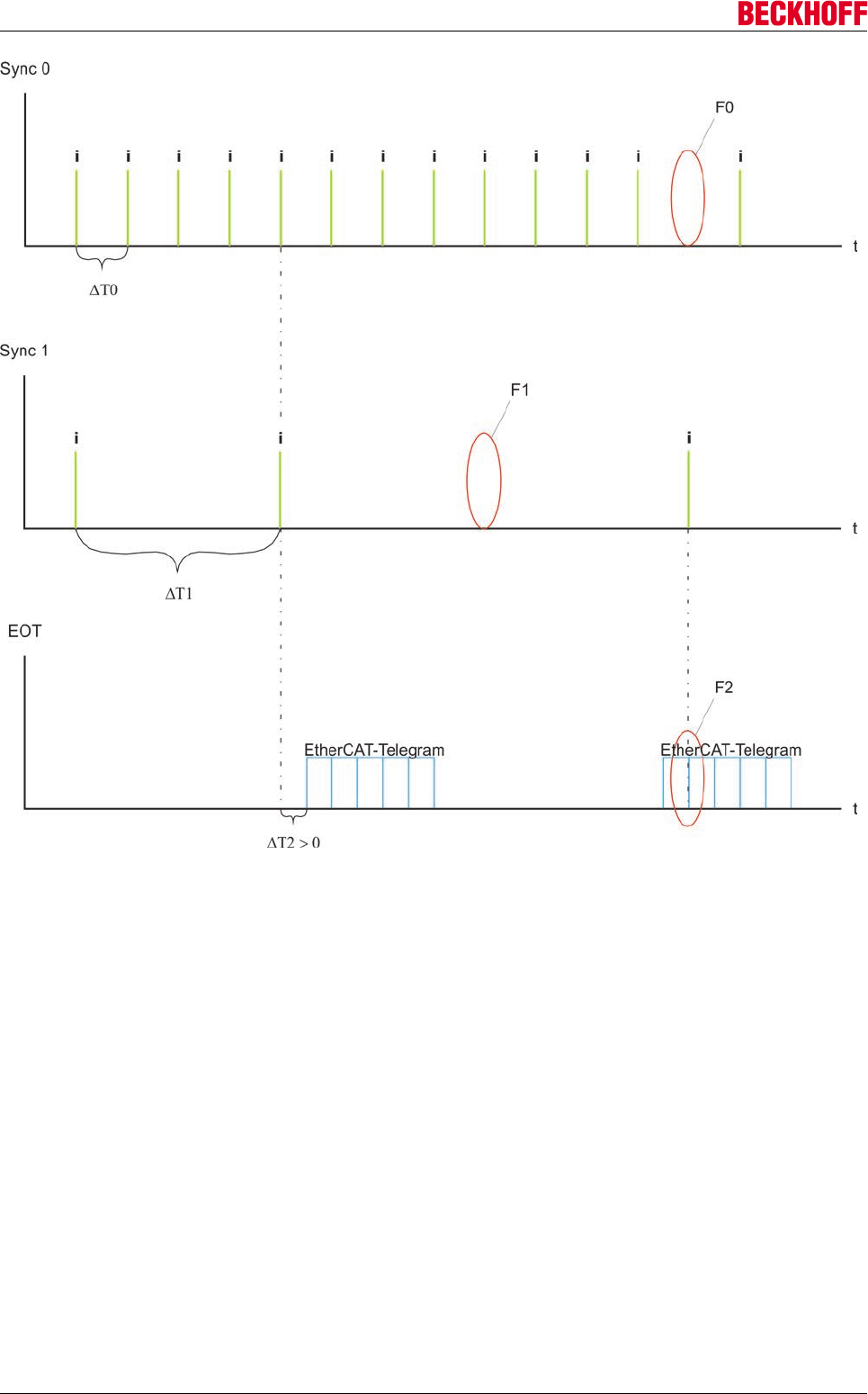
Advanced system characteristics
Servo Drives AX5000188 Version: 2.4
Special notes concerning the diagnostic message F415 "Distributed Clocks: process
data synchronization"
The real-time behavior of the machine is continuously monitored during operation. An important component
of this monitoring is the synchronization of all hardware and software components involved in data transfer.
The illustrations below represent a simplified example of this data transfer. The focus is on the drive tasks
"NC" and "PLC".
Sample 1
1. The CPU timer sends interrupts on a regular basis (default: base time = 1 ms)
2. The individual tasks are now processed in accordance with the rules of task management.
3. Task management:
Since the task takes up a greater or smaller amount of time due to a higher or lower number of com-
puting processes, the "I/O update" should be parameterized directly after the entry point (a) at the start
of the task. This excludes one source of incorrect synchronization.
A further source of error is an unfavorable prioritization of the individual tasks (see below).
4. Following the "I/O update", the resulting data are transferred to the TwinCAT-IO system and subse-
quently dispatched by EtherCAT telegram to the connected devices. The EtherCAT telegram passes
through each physically connected device and hands over or picks up only the data for this device.
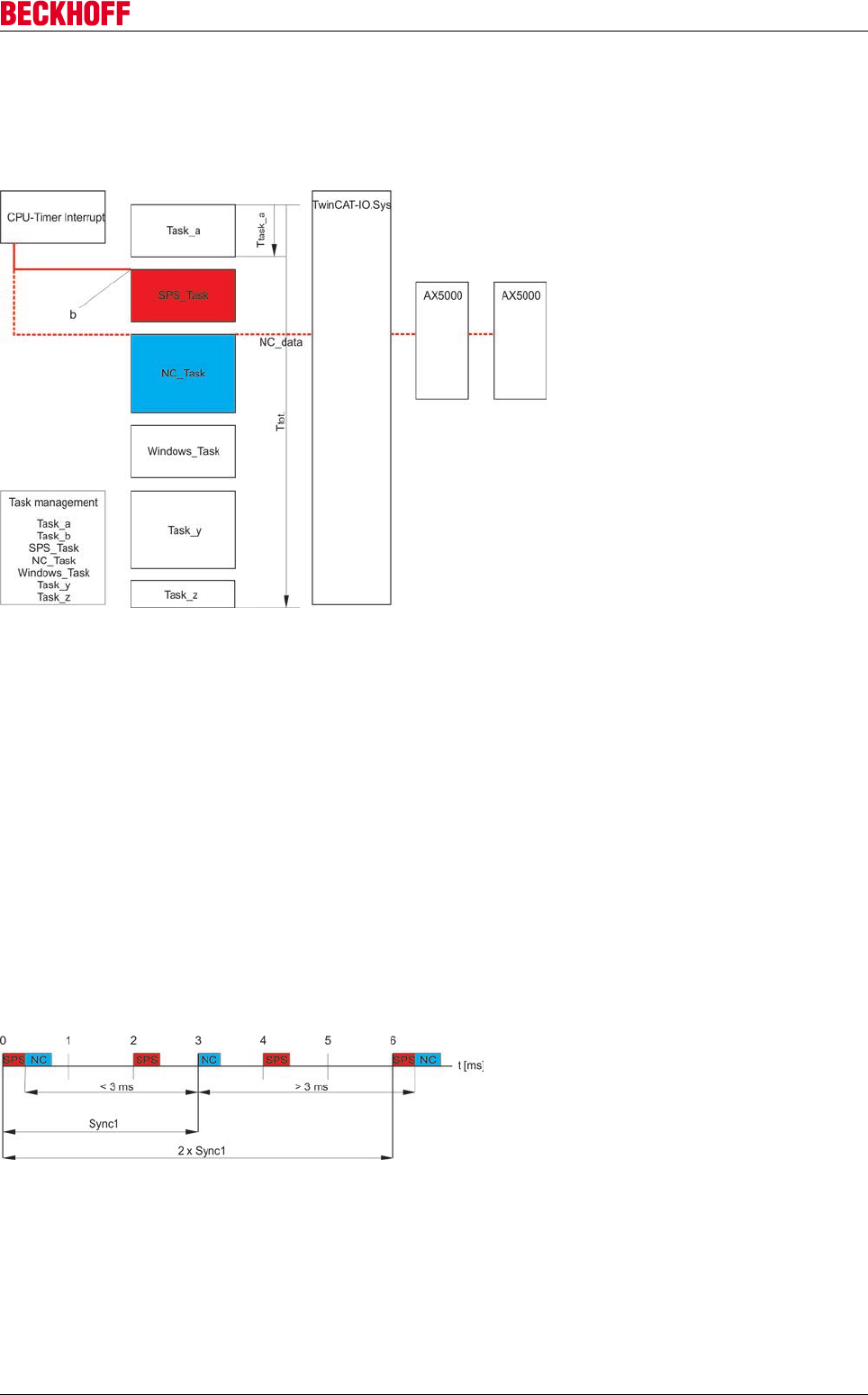
Advanced system characteristics
Servo Drives AX5000 189
Version: 2.4
5. The order of task calculation depends among other things on the prioritization of the tasks. If a task
has a higher priority, it is also calculated first and can send its data to the TwinCAT-IO system, which
then dispatches the telegram. Problems usually occur when individual tasks have different cycle times;
see below.
Prioritization
The following graph describes the effects of prioritization on the synchronization of the data.
Assumptions:
Sync1 = 3 ms
NC cycle time = 3 ms
NC priority = 10
PLC cycle time = 2 ms
PLC priority = 5
NC data are to be transmitted cyclically to the drive. Although the PLC requires time to compute, no data are
transmitted to the drive.
Due to its higher priority, the PLC task is always calculated before the NC task; these tasks affect each other
at the start point time "0 ms" and then repetitively every "6 ms", i.e. 2x Sync1. However, the ESC expects the
EtherCAT telegram with the NC data at each Sync1 (3 ms). That is not ensured, however, because the more
highly prioritized PLC task is always calculated before the NC task and thus in the case of synchronous
mapping the telegram start is delayed. For this reason the NC telegram arrives somewhat later every 6 ms
and can thus cause the F415 error in the AX5000.
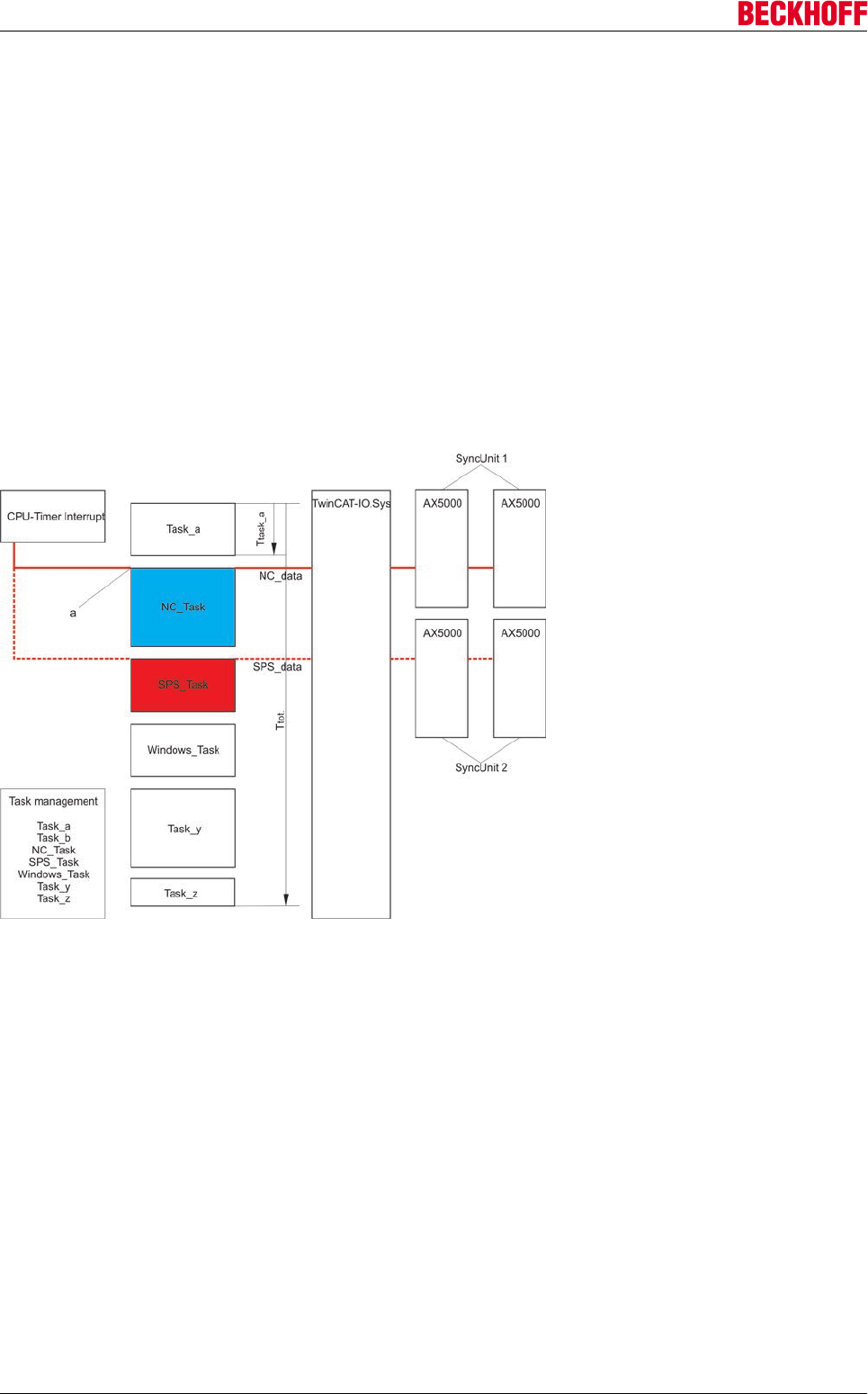
Advanced system characteristics
Servo Drives AX5000190 Version: 2.4
Sample 2
1. The CPU timer sends interrupts on a regular basis (default: base time = 1 ms)
2. The individual tasks are now processed in accordance with the rules of task management.
3. Task management:
Since the task takes up a greater or smaller amount of time due to a higher or lower number of com-
puting processes, the "I/O update" should be parameterized directly after the entry point (a) at the start
of the task. This excludes one source of incorrect synchronization.
A further source of error is an unfavorable prioritization of the individual tasks (see below).
4. Following the "I/O update", the resulting data are transferred to the TwinCAT-IO system and subse-
quently dispatched by EtherCAT telegram to the connected devices. The EtherCAT telegram passes
through each physically connected device and hands over or picks up only the data for this device.
5. The order of task calculation depends among other things on the prioritization of the tasks. If a task
has a higher priority, it is also calculated first and can send its data to the TwinCAT-IO system, which
then dispatches the telegram. Problems usually occur when individual tasks have different cycle times;
see below.
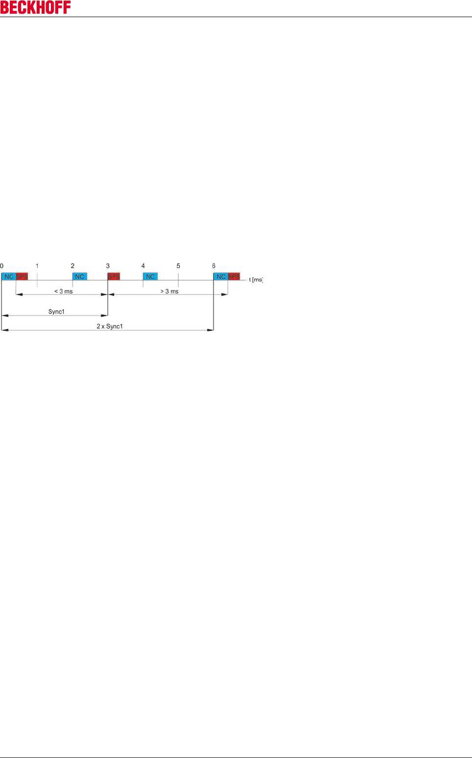
Advanced system characteristics
Servo Drives AX5000 191
Version: 2.4
Prioritization
The following graph describes the effects of prioritization on the synchronization of the data.
Assumptions:
Sync1 = 3 ms
NC cycle time = 2 ms
NC priority = 5
PLC cycle time = 3 ms
PLC priority = 25
NC task serves only devices in SyncUnit 1, synchronous mapping
PLC task serves only devices in SyncUnit 2, synchronous mapping
NC and PLC data are to be transferred cyclically.
Due to its higher priority, the NC task is always calculated before the PLC task and the telegram is
accordingly also sent first; these tasks affect each other at the start point time "0 ms" and then repetitively
every "6 ms", i.e. 2x Sync1. However, the ESC expects an EtherCAT telegram at each Sync1 (3 ms). This is
not a problem in SyncUnit 1, which is served by the NC, since the more highly prioritized NC always sends
the telegram in the same time pattern. However, the PLC telegram arrives somewhat later every 6 ms and
can thus cause the F415 error in the AX5000 in SyncUnit 2.
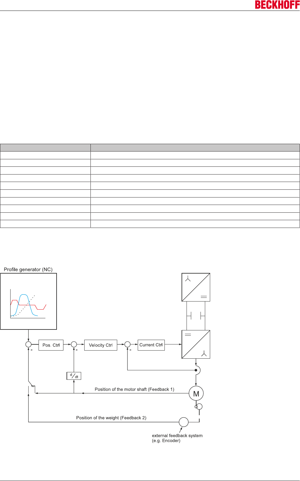
Advanced system characteristics
Servo Drives AX5000192 Version: 2.4
10.3 Operation modes
In drive technology a distinction is made between the following operation modes:
• Current / torque control
• Speed control
• Position control
In the SoE standard the individual operation modes are specified via the standard parameter S-0-0032 (main
operation mode).
10.3.1 Mode parameterisation according to SoE
Parametrization of the IDN S-0-0032
Bit Operation mode
0 no mode of operation
1 torque control
2 velocity control
3 position control feedback 1
4 position control feedback 2
11 and 12 position ctrl feedback 1 + 2 lag less
32769 torque control using dynamic MDT
32770 velocity control using dynamic MDT
32771 and 32772 position control feedback 1 + 2 using dynamic MDT
32779 and 32780 position control feedback 1 + 2 lag less using dynamic MDT
Cascaded control structure
The diagram shows a typical control structure with higher-level position controller and subordinate speed and
current controller.
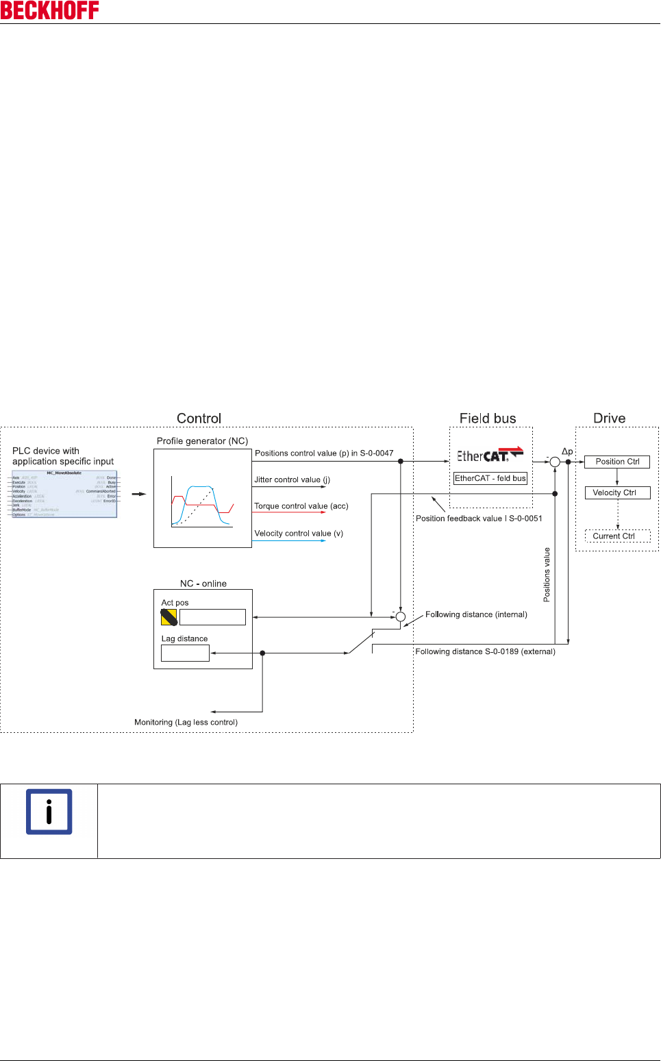
Advanced system characteristics
Servo Drives AX5000 193
Version: 2.4
A cascaded controller structure consisting of current, speed and position controllers has proven to be
necessary for achieving high dynamics and positioning accuracy. The diagram illustrates the time constants
of the individual control loops, rising from inside to outside. Two operating modes are suitable for positioning:
velocity set value specification or position set value specification.
For the position of operation, 2 modes are:
• • speed setpoint (speed interface):
Cyclic speed setpoints are sent from the controller to the drive. Of the Position controller is in this case
on the side of the controller (NC) implemented.
• • Position setpoint. (Position interface):
Cyclic setpoint positions are sent from the controller to the drive. The position controller is here
implemented in the drive. In the control (NC) only the setpoint profile is calculated. Here is a higher
bandwidth in the position control achieved (no EtherCAT dead in closed Loop). This mode should
always be used when the controller enables.
Profile generator
The profile generator generates curve profile of a positioning job of the PLC function block
MC_MoveAbsolute. In each NC cycle, at a specified time (node T1 - Tn), the Setpoints this positioning task
passed to the axis control. Thus, the servo amplifier optimally can proceed, the target values of the profile
generator with the SAF task of the EtherCAT fieldbus must be triggered. The SAF task ensures that the
support points (T1 - Tn) to the servo amplifier be transported.
MC_MoveAbsolute is primarily used for linear axis systems. This PLC function block, let to axes with a speed
v process of starting to target positions.
Note
For further informations, please look at the following link:
PLC ( Libs ( TwinCAT 3 PLC lib: Tc2_MC2 ( Motion-Function block ( Point to Point Motion
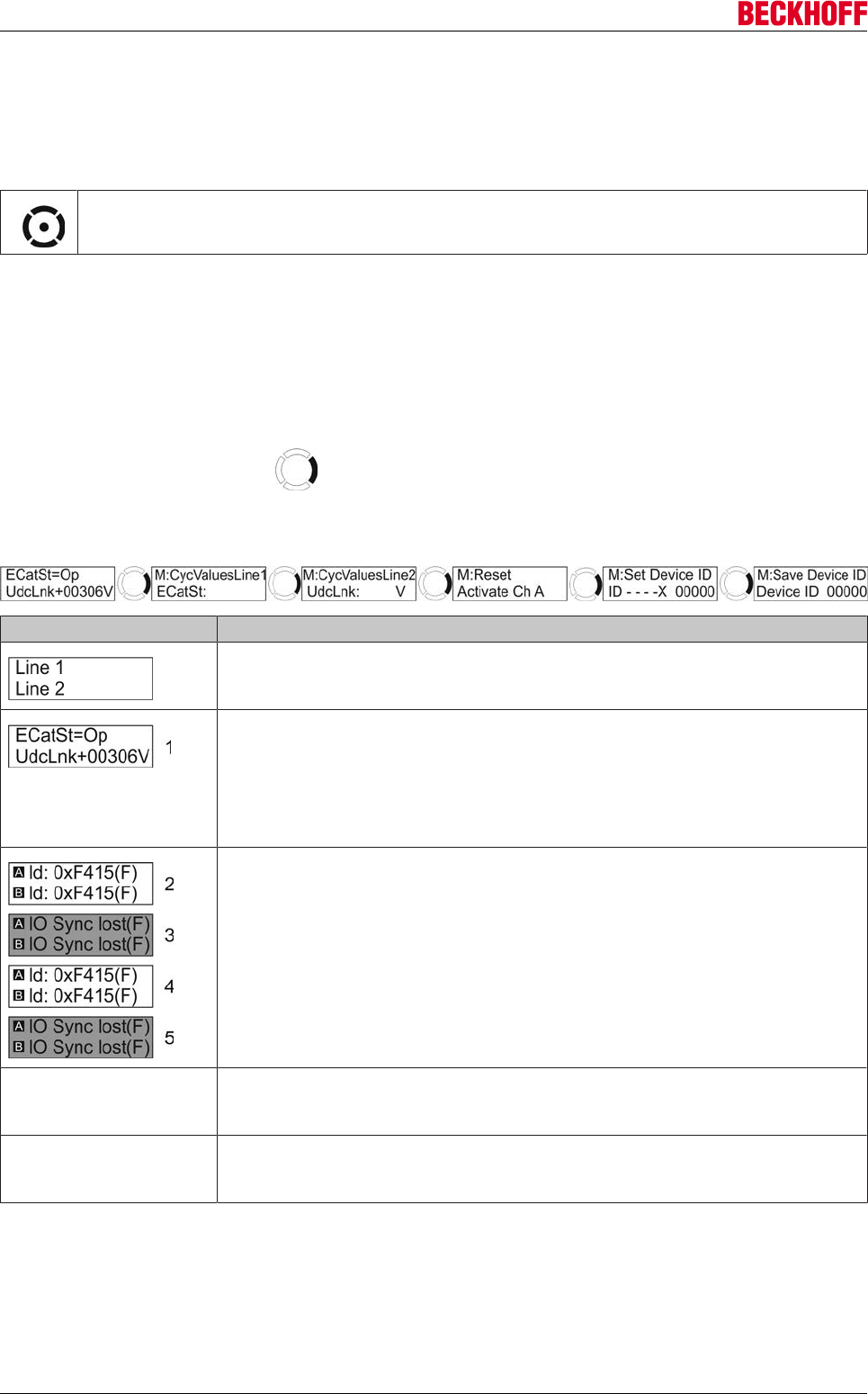
Advanced system characteristics
Servo Drives AX5000194 Version: 2.4
10.4 Display and navigation rocker
10.4.1 Navigation rocker
The navigation rocker is used for navigating within the display. It has 5 contact points: “right”, “left”,
“top”, “bottom” and “centre”
10.4.2 Display
General
Starting from the standard display, you can access the configuration and command displays by pressing the
right side of the navigation rocker . Except with the standard display, if you do not change the display
for approx. 25 seconds, the standard display is automatically shown again. The standard display is always
shown if the device is working perfectly.
Display Description
The display consists of 2 lines. These two lines display independent,
configurable contents.
The contents can be arranged into 4 groups.
Cyclic values (standard display):
The so-called standard display is shown permanently. The values provided can
be displayed in the two lines. The two lines are preconfigured in the factory as
follows:
Line 1: EtherCAT status
Line 2: DC link voltage
Error messages:
If an error occurs, the diagnostic code (hex) and a short version of the message
(2+3) are shown alternately on the display. If the error concerns only channel
"A", then this display is shown only in the upper line; the standard text remains in
the lower line. If the error concerns only channel "B", then this display is shown
only in the lower line; the standard text remains in the upper line. In both cases
the display additionally flashes (2-5).
If the error has been rectified and acknowledged with the reset command
(S-0-0099), the standard display with the cyclic values appears again (see
above).
see error messages Warnings:
If a warning occurs, the display behaves in the same way as with an error
message.
see error messages Information messages:
If an information message occurs, the display behaves in the same way as with
an error message, but does not flash.
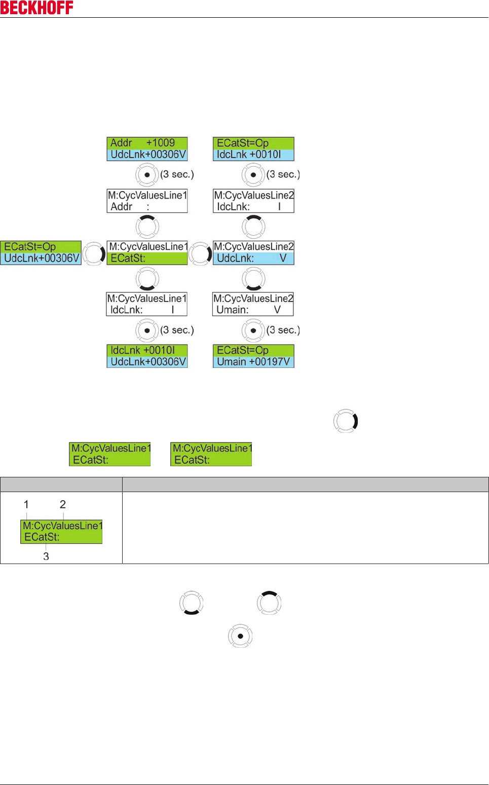
Advanced system characteristics
Servo Drives AX5000 195
Version: 2.4
Cyclic values
The two lines with the cyclic values, which are shown on the standard display, are freely configurable. You
can choose from 51 different cyclic values. The values are saved in IDNs and retrieved from there. The
procedure for configuring line 1 and line 2 is identical:
Overview (example)
Changing the display
Starting from the standard display, press the right-hand side of the rocker 1x (for line 1) or 2x (for line
2); the display or appears.
Display Description
1 = "M" indicates that the "menu mode" is activated.
2 = The "CycValuesLine1" menu is active. This means that the cyclic values are
displayed in line 1.
3 = Indicates which cyclic values are currently displayed.
The currently displayed value determines the point of entry into the list of the cyclic values. You can change
to the next cyclic value with the bottom or the top side of the rocker, as shown below. If the
desired value has been reached, press the center of the rocker for 3 seconds. The value is adopted
and the changed standard display is shown.
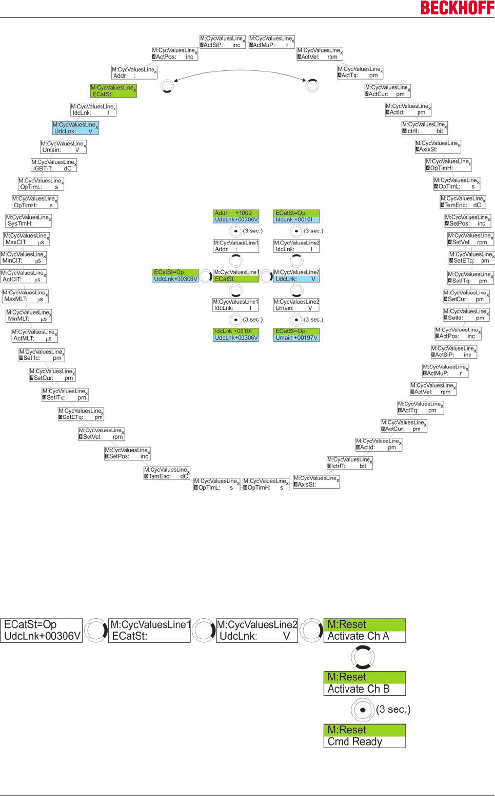
Advanced system characteristics
Servo Drives AX5000196 Version: 2.4
Error reset (command S-0-0099)
After rectifying an error, it is necessary to perform an error reset. The associated command is the IDN
S-0-0099. This command can also be given directly via the display. As soon as an error occurs the display
flashes continuously; the standard display is shown again and the flashing stops only after a successful error
reset.
Overview
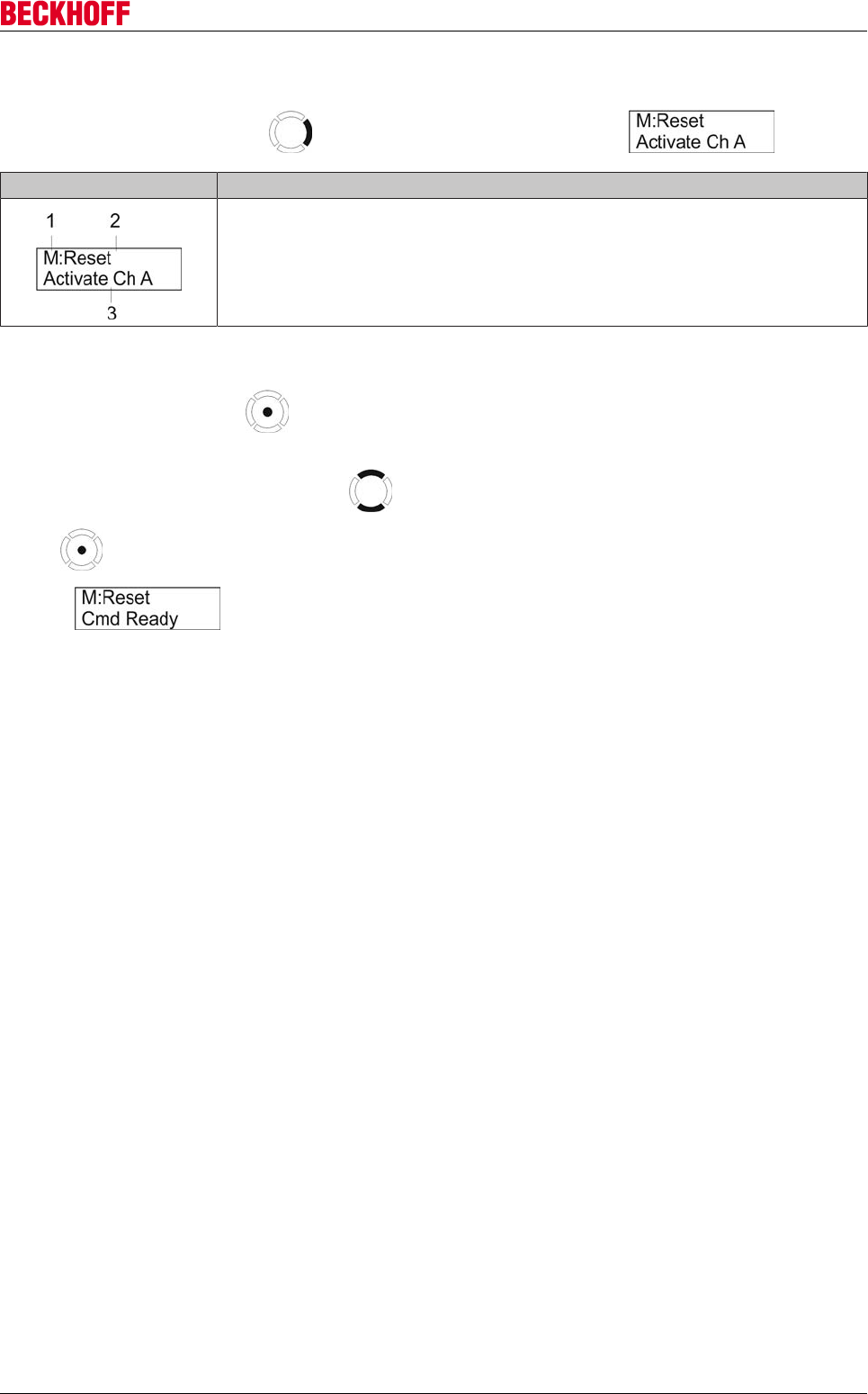
Advanced system characteristics
Servo Drives AX5000 197
Version: 2.4
Executing the command
Press the right side of the rocker 3x until the following display appears:
Display Description
1 = "M" indicates that the "menu mode" is activated.
2 = The "Reset" menu is active.
3 = Indicates which channel of the AX5000 the reset affects.
There are now 2 possibilities:
Press the center of the rocker for approx. 3 sec. to execute the reset command for channel "A"
or
Press the upper or lower side of the rocker and switch to channel "B". Now press the center of the
rocker for approx. 3 seconds and execute the Reset command for channel "B". The following display
appears .
The standard display should appear again after approximately 25 seconds. If the error display is still visible
after that, this means that you have not rectified the cause of the error, or that there are further errors.
Device ID
The Device ID is a configurable ID of the AX5000 in the system environment. It is saved in the IDN
P-0-0020.
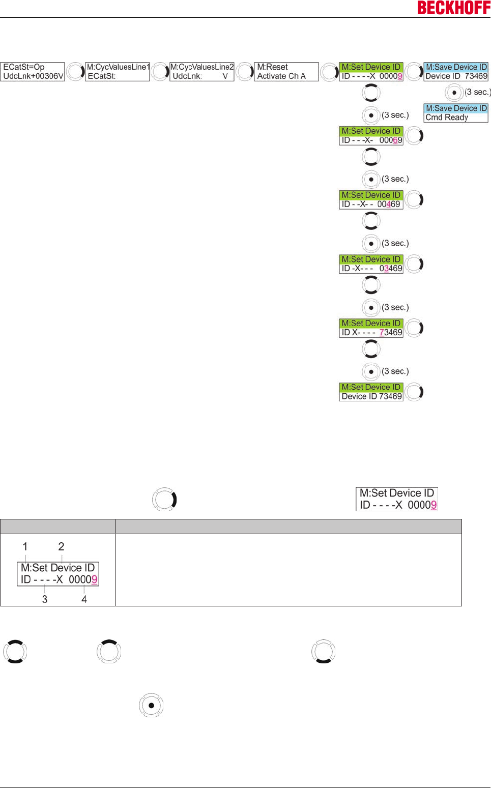
Advanced system characteristics
Servo Drives AX5000198 Version: 2.4
Overview (example)
Entering the Device ID
You can edit the 5-digit Device ID by entering the individual digits. The prerequisite for this is that the "Set
Device ID" menu is active. As mentioned above, the display of the AX5000 displays freely configurable cyclic
data in the upper and lower lines as standard.
Press the right side of the rocker 4x until the following display appears:
Display Description
1 = "M" indicates that the "menu mode" is activated.
2 = The "Set Device ID" menu is active.
3 = Indicates which digit "X" of the Device ID is currently editable;
in this example it is the last digit, i.e. "nine".
4 = Device ID
You can now immediately edit the last digit of the Device ID by pressing the top or bottom side of the rocker
. The top side increments the number, the bottom side decrements it. After you have set
the digit, there are 2 possibilities:
Press the center of the rocker for approx. 3 sec. and you can then edit the digit to the left of the
current digit.
or
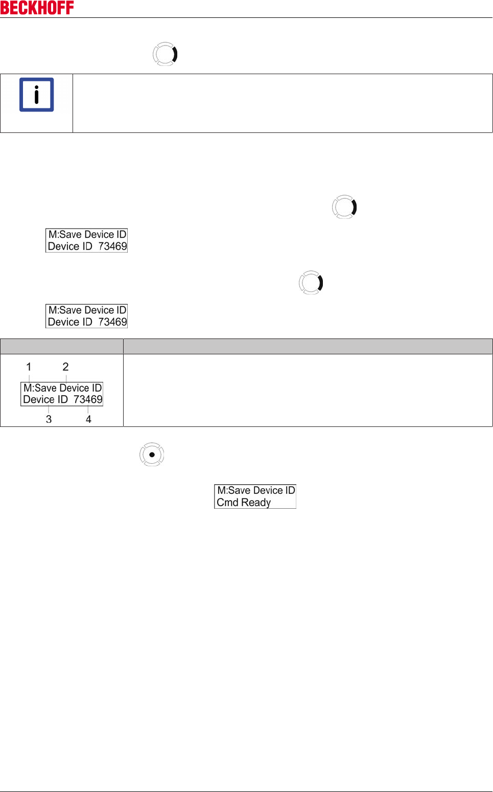
Advanced system characteristics
Servo Drives AX5000 199
Version: 2.4
Press the right side of the rocker ; this takes you to the "Save Device ID" menu.
Note
Temporary memory
After you have finished editing, the changed Device ID is located in a temporary memory,
which is cleared when the AX5000 is switched off. You must execute the command "Save
Device ID", so that the Device ID is saved permanently in the AX5000.
Saving the Device ID
By means of saving the Device ID, the IDN P-0-0020 is written to the AX5000 and can be used further.
If you have just changed the Device ID, press the right side of the rocker and the following display
appears:
If the standard display is visible, press the right side of the rocker 5x until the following display
appears:
Display Description
1 = "M" indicates that the "menu mode" is activated.
2 = The "Save Device ID" menu is active.
3 + 4 = Indicates which Device ID will be saved.
Press the center of the rocker for approx. 3 sec. in order to save the displayed Device ID.
If saving was successful, this display appears: .
The standard display appears again after approximately 25 seconds.
Advanced system characteristics
Servo Drives AX5000200 Version: 2.4
10.5 Motor brake management
10.5.1 IDNs involved
IDN Name
S-0-0206 Drive on delay time
S-0-0207 Drive off delay time
P-0-0058 Motor brake type
P-0-0096 Motor control word
P-0-0097 Motor status word
10.5.2 Functioning
IDN S-0-0206 determines the time of the motor standstill after the motor current feed, so that the brake can
vent first.
IDN-S-0-0207 defines the switch-off delay between activation of the motor brake and deactivation of the
current feed.
IDN-P-0-0058 is used to configure the motor brake.
IDN-P-0097 displays the state of the motor brake.
IDN-P-0096 can be used to release the motor brake manually or requesting activation of the brake manually.
This bits overwrite the internal brake request. The brake is therefore released or engaged irrespective of the
motor current feed and any travel command.
WARNING
Risk of injury!
Improper operation of IDN P-0-0096 can therefore lead to sagging of a non-energized Z
axis or closing of the motor brake at full speed!
10.6 Commutation methods
The important characteristics of a servomotor, such as its very smooth running, high efficiency and optimum
thermal utilization, are strongly influenced by the commutation. Commutation refers to the transfer of current
from one winding to the next. The moment at which commutation takes place must be harmonized with the
magnetic field of the rotor if the servomotor is to operate most effectively.
10.6.1 Rotary servomotors
10.6.1.1 Mechanical commutation
These motors, which use brushes, generate the alternating fields necessary for operation of the motor
through sliding contacts, whose geometrical arrangement switches the current paths. Brush losses and wear
are disadvantages of this simple, mechanical commutation method.
10.6.1.2 Electronic commutation
These modern motors generate the alternating field needed for operation of the motor by means of an
electronic circuit which is not subject to either wear or friction. The type of motor and the encoder system in
use determine the commutation method.

Advanced system characteristics
Servo Drives AX5000 201
Version: 2.4
Absolute encoder system (motor feedback) within one rotation
Samples of this type of encoder system includes: Resolver, EnDat, BiSS and HIPERFACE
Two different commutation methods are involved here:
Mechanical adjustment of the encoder
The motor's encoder system is mechanically adjusted at the factory (the encoder and rotor are matched to
one another), but the rotor position is unknown.
The commutation angle is determined once by the P160 command, using the IDN "P0-0-165_Command
mode_Static current vector" and the IDN "P-0-057 "Electrical commutation offset". This means that the
corresponding mechanical angle coming from the encoder system is displayed and read out in P-0-0058,
and is saved in the IDN "P-0-0150_Parameter chanel_Adjustable commutation offset" (motor database). In
order for the parameter to be used, the IDN "P-0-0150_Parameter chanel_Commutation mode" (motor
database) must be set to 3: "Adjustable offset". The associated value of the IDN "P-0-057 "Electrical
commutation offset" is also saved in the motor database.
Electronic adjustment of the encoder system
Note
Synchronous motors!
Electronic adjustment is only required for synchronous motors. In the case of a synchro-
nous motor, the magnetic field of the rotor is generated electronically, and therefore can be
set appropriately for the electromagnetic field of the winding.
Depending on the encoder system there are, again, two different commutation methods:
1. The encoder is always attached to the rotor by the manufacturer in the same rotary position, but the
rotor position is not known.
The commutation angle is determined once by the P160 command, using the IDN "P0-0-165_Com-
mand mode_Static current vector" and the IDN "P-0-057 "Electrical commutation offset". This means
that the corresponding mechanical angle coming from the encoder system is displayed and read out in
P-0-0058, and is saved in the encoder system's data store (exceptionally) and in the IDN
"P-0-0150_Parameter chanel_Adjustable commutation offset" (motor database). In order for the pa-
rameter to be used, the IDN "P-0-0150_Parameter chanel_Commutation mode" (motor database)
must be set to 3: "Adjustable offset". The associated value of the IDN "P-0-057 "Electrical commuta-
tion offset" is also saved in the motor database. This method requires a encoder system having a data
store and a data line.
2. The angle between the encoder system and the rotor is determined by the motor manufacturer using a
command that is specific to the encoder, and is communicated to the encoder system. The encoder
system stores this angle, using it for internal calculation, but the rotor position is unknown.
The commutation angle is determined once by the P160 command, using the IDN "P0-0-165_Com-
mand mode_Static current vector" and the IDN "P-0-057 "Electrical commutation offset". This means
that the corresponding mechanical angle coming from the encoder system is displayed and read out in
P-0-0058, and is saved in the encoder system's data store (exceptionally) and in the IDN
"P-0-0150_Parameter chanel_Adjustable commutation offset" (motor database). In order for the pa-
rameter to be used, the IDN "P-0-0150_Parameter chanel_Commutation mode" (motor database)
must be set to 3: "Adjustable offset". This angle is always included in internal calculation processes.
This method requires an intelligent encoder system.
Non-absolute encoder system (feedback) within one rotation
Samples of this type of encoder system includes: SIN / COS 1Vss
In this case, a special commutation procedure (wake&shake) must be run in order to determine the
commutation angle. This angle is stored internally, and is taken into account during operation. If the AX5000
is switched off, or if the "EtherCAT-State machine" is switched into "Pre-op" or a lower state, the
commutation angle will be lost because the encoder system is not absolute. "Wake&shake" can only operate
without error when the drive system is running steadily; in other words there must not be any vibrations
affecting the motor from outside. In addition, a stability investigation using the default values of the "IDN
P-0-0165" is necessary the first time the system is operated.
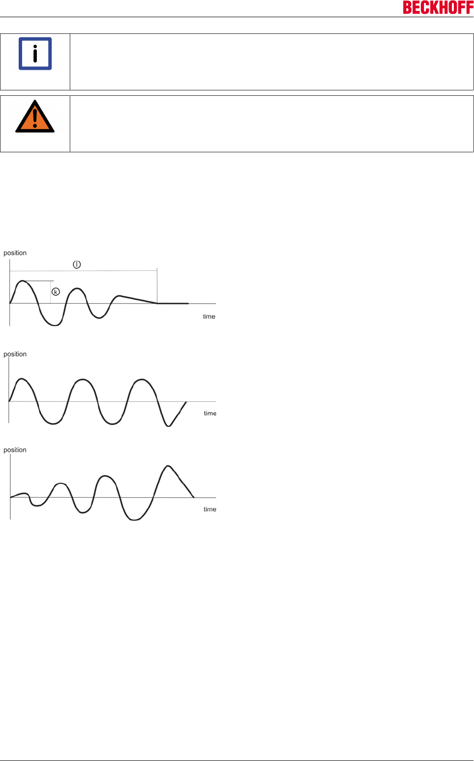
Advanced system characteristics
Servo Drives AX5000202 Version: 2.4
Note
Oscillatory system!
It is important for this stability investigation to examine the application in advance and to
determine the oscillation that is potentially most problematic. This case can occur under
load conditions, or may be found when unloaded.
WARNING
Warning, risk of injury from uncontrolled movements!
In the method described below, the motor shaft is brought directly to a certain position.
Make sure that your application permits this movement, secure the surroundings to prevent
unintentional entry, and make sure that nobody is in the hazardous area.
Oscillatory system
It is necessary to analyze the vibration pattern of an oscillating system, and to take appropriate damping
measures. Oscillations always have their effect in Phase 2 of "wake&shake"; oscillations are not particularly
critical in Phase 1.
Decaying oscillation
The amplitude (k) and the decay time (l) of this
kind of oscillation must be found. The parameters
IDN-P-0-0165 "Commutation pos control: Kp" can
affect both the amplitude (k) and the decay time
(l). The parameter IDN-P-0-0165 " Second phase
duration" should be greater than the decay time
(l).
Constant oscillation
This kind of oscillation is unacceptable, as a
stable regulation process is not established. The
parameters IDN-P-0-0165 "Commutation pos
control: Kp" must be checked, and modified if
necessary. If this does not achieve the desired
result, you must damp the vibration mechanically.
Rising oscillation
This kind of oscillation is unacceptable, as a
stable regulation process is not established. The
parameters IDN-P-0-0165 "Commutation pos
control: Kp" must be checked, and modified if
necessary. If this does not achieve the desired
result, you must damp the vibration mechanically.
The motor shaft is brought to freely definable electrical positions by impressing an appropriate current in the
course of this investigation. When this injected current is switched off, the motor should remain in the
position that it has reached. BECKHOFF recommends positions of 0°, 90°, 180° and 270°. In critical
applications, eight positions (0°, 45°, 90°, 135° ...315°) should be selected instead of four. The current
injection is parameterized in the IDN P-0-0165 under "Static current vector", while the freely selectable
electrical position is set in the IDN P-0-0057. "Wake&shake" should be carried out in each position; stability
of the system is only ensured when this has been done successfully.

Advanced system characteristics
Servo Drives AX5000 203
Version: 2.4
Wake&shake
Note
Oscillating system!
A mechanical remedy must be provided if the application oscillates. You can carry out the
commutation up to a degree using wake&shake, but should carefully select the parameters
for the IDN "P-0-0165" to make the effect of the oscillation as small as possible, since too
much post-pulse oscillation will cause a commutation error. This is because the angle mea-
sured after completing the command will be entered as the commutation angle.
WARNING
Warning, risk of injury from uncontrolled movements!
The motor shaft will be moved in steps during the process described below. In Phase 1 the
maximum electrical movement is 8 x (the value from "P-0-0-0165_Fist phase position moni-
toring limit"). In Phase 2it is 0.5 x (the value from "P-0-0-0165_Fist phase step width"). This
formula can only be applied if the previous investigation of stability has been concluded sat-
isfactorily. Make sure that your application permits this movement, secure the surroundings
to prevent unintentional entry, and make sure that nobody is in the hazardous area.
The wake&shake commutation function consists of two phases. An approximate determination of the rotor
position is carried out in Phase 1, while Phase 2 determines the position more precisely. The aim of the
commutation function is to determine the precise position of the rotor with a minimum amount of movement.
Due to the pairs of poles, servomotors exhibit a direct relationship between the electrical and mechanical
rotation. One electrical rotation always corresponds to one mechanical rotation divided by the number of pole
pairs. A motor with a single pair of poles is illustrated in the following example for the sake of simplifying the
calculation.
Parameterization is carried out using the IDN P-0-0165 "Commutation offset calibration parameter". The
quoted angles always refer to electrical rotations!
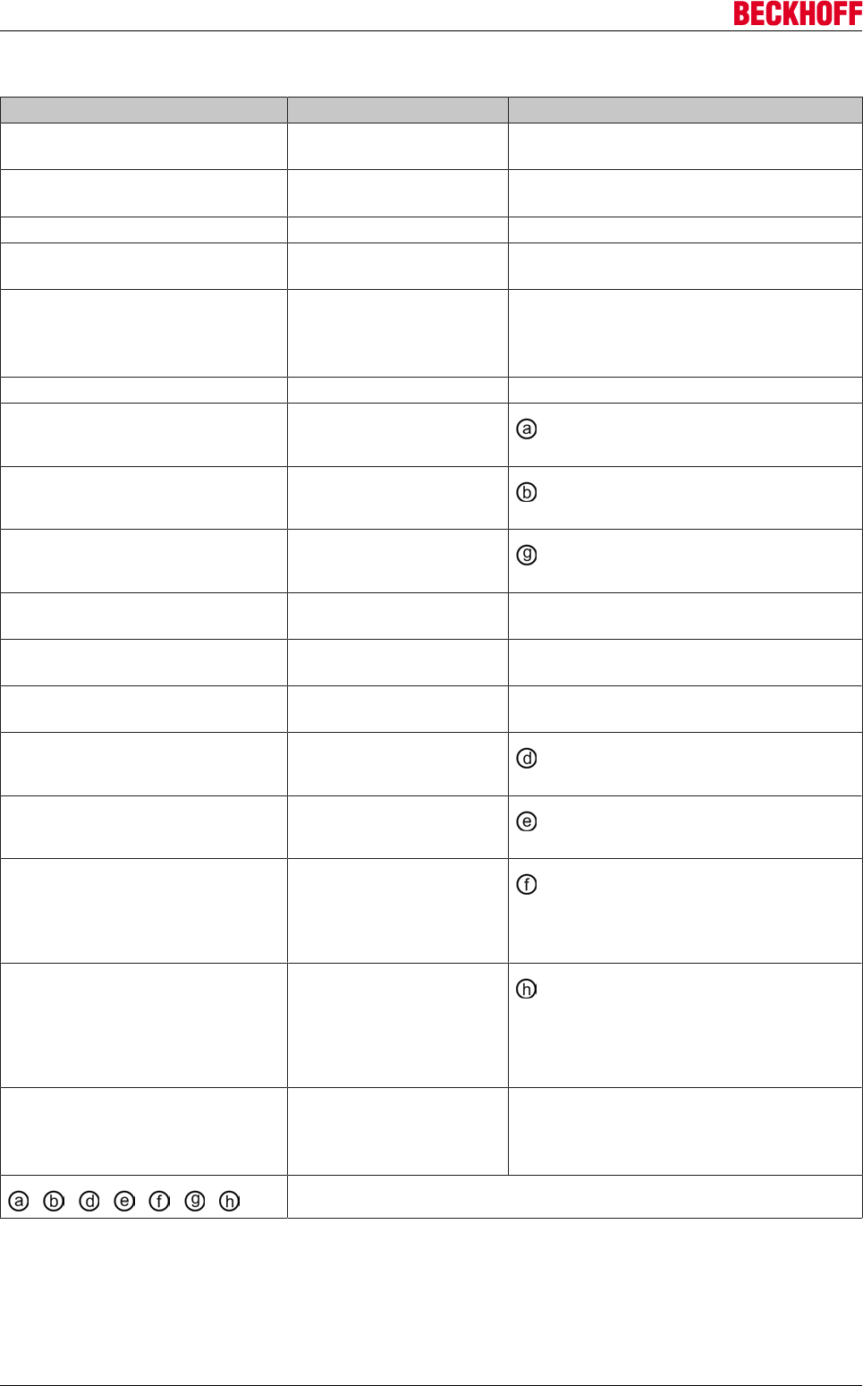
Advanced system characteristics
Servo Drives AX5000204 Version: 2.4
IDN P-0-0165 - Commutation offset calibration parameter
Parameter Default Description
Command mode 0: Static current vector Selection between two commutation
methods
Activation 0: manual Selection of when the commutation process
is started
Static current vector Commutation methods
Current level Stationary current in % Current intensity of the current vector (value
= 100% x P0-0093 / P0-0092)
Duration 3000ms Period for which the parameterized current
is maintained so that any oscillations that
may be present can settle, allowing an
optimum commutation angle to be reached
Wake and shake Commutation methods
First phase current vector Stationary current in % Current intensity of the current vector
(value = 100% x P0-0093 / P0-0092)
First phase ramp up time 100ms Time for the current vector "a" to reach
its parameterized magnitude
Second phase current level Stationary current in % Current intensity of the current vector
(value = 100% x P0-0093 / P0-0092)
Second phase ramp up time 500ms Time for the current vector "g" to reach its
parameterized magnitude
Commutation pos control: Kp 0.04 Amplification factor. Attention: If "0" then
Variant 2 will be carried out in Phase 2
Wake and shake expert Attention: Only experienced users should
change the following parameters!
First phase pos monitoring limit 0.5 degrees Minimum angle of rotation of the rotor
required to detect movement
First phase step width 22.5 degrees Current vector offset or segment
detection angle
First phase waiting time after step 150ms The time from detection of movement
and the next step in Phase 1 or between
Phase 1 and Phase 2 (any oscillations in
the system have time to settle)
Second phase duration 3000ms Period for which the parameterized
current is maintained so that any
oscillations that may be present can settle,
allowing an optimum commutation angle to
be reached
Error monitoring (range of motion) 90 degrees The maximum movement of the rotor
before it is switched off, since there would
otherwise be a risk that the motor would
make an uncontrolled movement.
= identifying characters for the description below
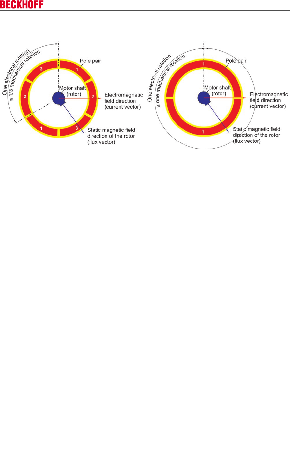
Advanced system characteristics
Servo Drives AX5000 205
Version: 2.4
Motor with 3 pole pairs Motor with one pair of poles
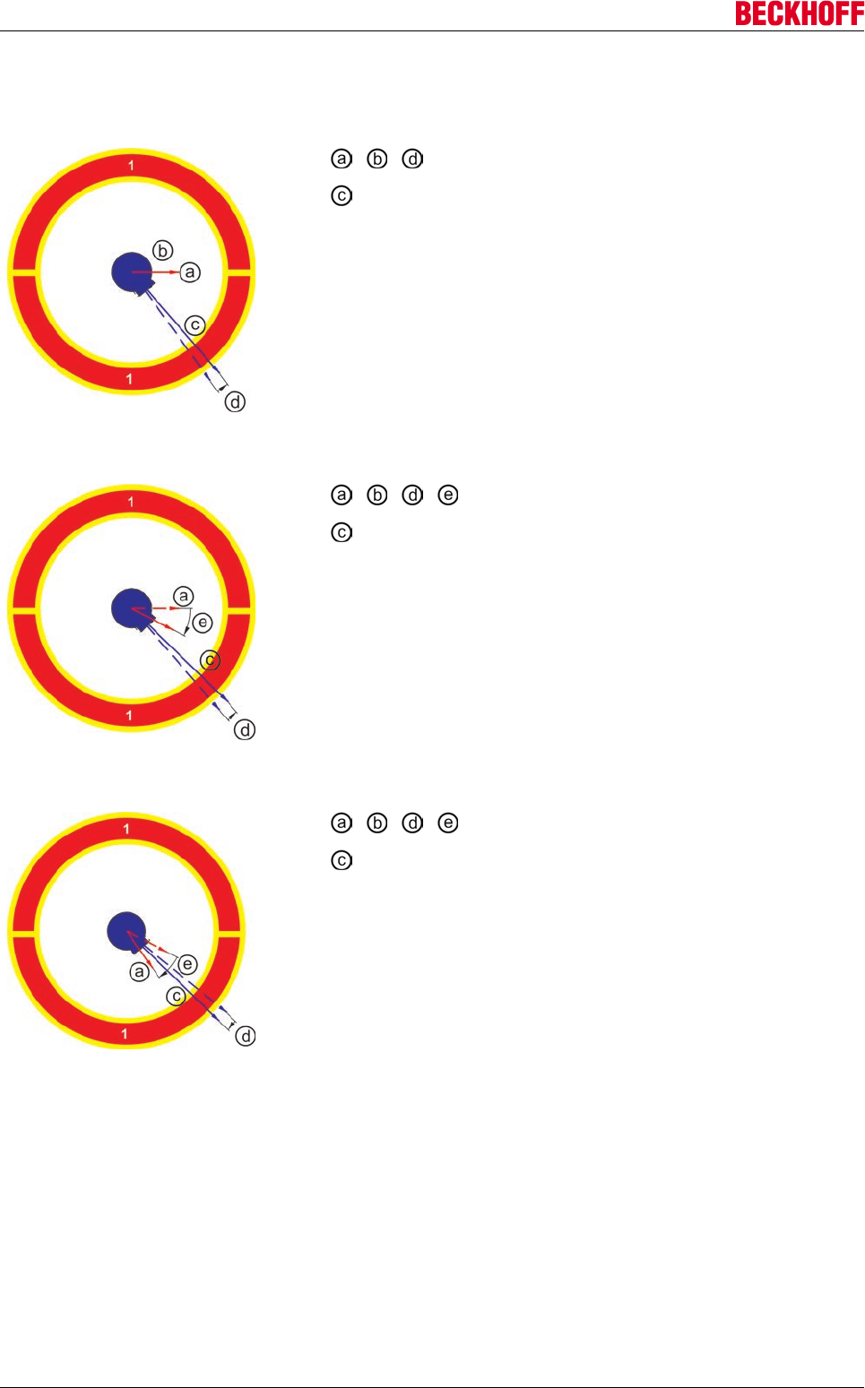
Advanced system characteristics
Servo Drives AX5000206 Version: 2.4
Phase 1 - approximate determination of the rotor position (motor shaft)
Step 1:
= see IDN P-0-0165 parameter description above
= flux vector of the rotor with permanent magnet.
Sequence:
A current vector "a" is developed during the time "b". Due to the
rising magnetic force, the rotor "c" is turned in the direction of the
current vector "a". The direction of rotation "d" is transmitted to the
feedback system and the AX5000, where it is stored.
Step 2:
= see IDN P-0-0165 parameter description above
= flux vector of the rotor with permanent magnet.
Sequence:
A current vector "a" is developed during the time "b". Due to the
rising magnetic force, the rotor "c" is turned in the direction of the
current vector "a". The direction of rotation "d" is transmitted to the
feedback system and the AX5000, where it is stored and analyzed.
If the analysis shows that the direction of rotation "d" of the rotor "c"
has not changed when compared with that of the previous
impressed current, the process continues.
Step 3:
= see IDN P-0-0165 parameter description above
= flux vector of the rotor with permanent magnet.
Sequence:
The current vector "a" is again set to the magnitude "e" in the
direction of the rotor "c".
The current vector "a" is now again developed during the time "b".
Due to the rising magnetic force, the rotor "c" is turned in the
direction of the current vector "a". The direction of rotation "d" is
transmitted to the feedback system and the AX5000, where it is
stored and analyzed. In this case, the analysis shows that the
direction of rotation "d" of the rotor "c" has changed when
compared with that of the previous impressed current. As a result,
the sector in which the rotor "c" is located has been found, and
Phase 1 is therefore completed.
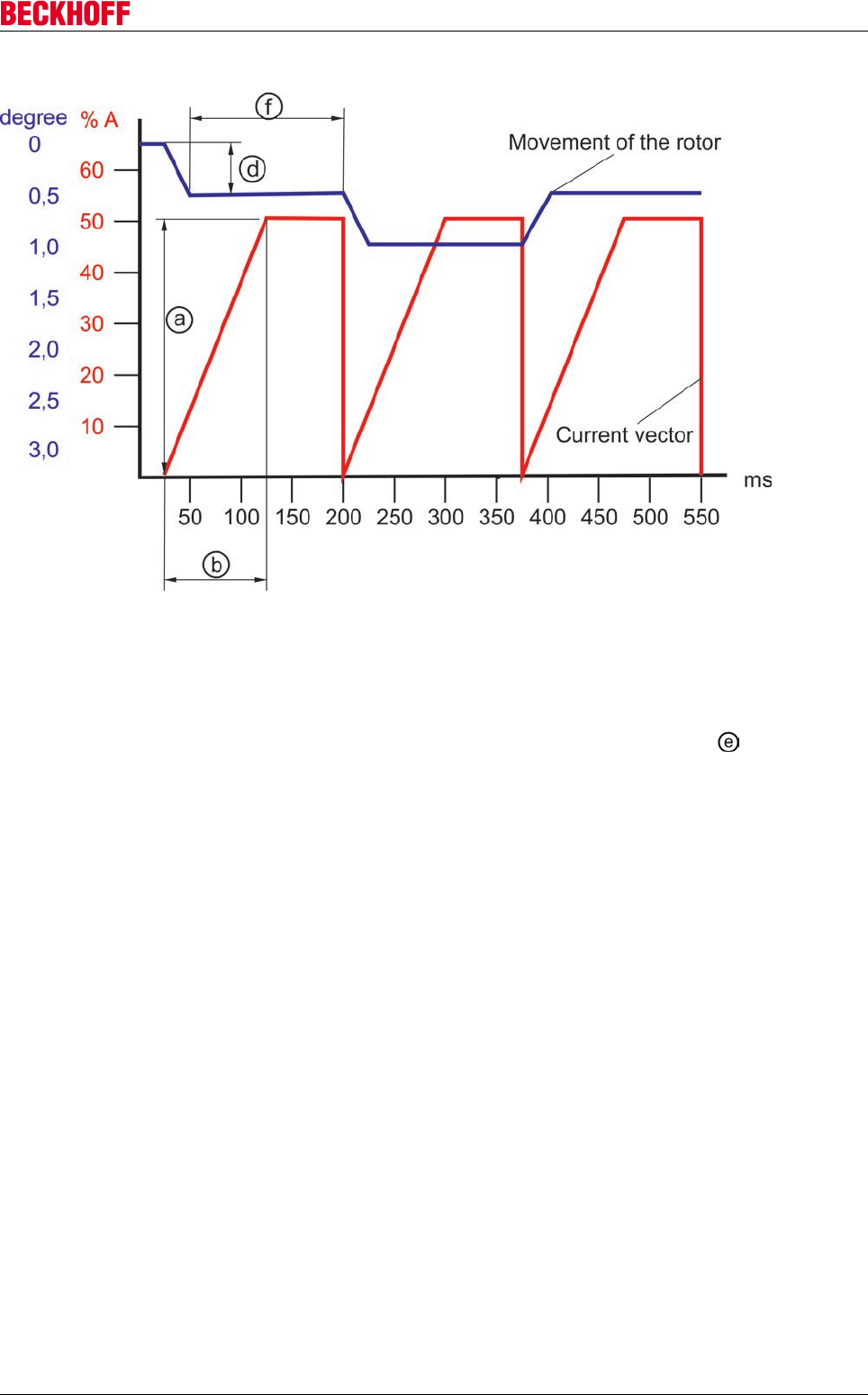
Advanced system characteristics
Servo Drives AX5000 207
Version: 2.4
Example of an oscilloscope display of Phase 1:
Phase 2 - precise determination of the rotor position (motor shaft)
There are two variants of the precise localization that may be used in Phase 2. In the first variant, the rotor
only makes minimal movement, but this does require a very stable system with only a slight tendency to
oscillate. In the second variant, the rotor can move by up to a maximum of half the sector , but this
method is much more tolerant against oscillation.
The value set in the parameter IDN-P-0-0165 "Commutation pos control: Kp" controls which variant is used:
IDN-P-0-0165 "Commutation pos control: Kp" > 0 --> Variant 1
IDN-P-0-0165 "Commutation pos control: Kp" = 0 --> Variant 2
Variant 1 (IDN-P-0-0165 "Commutation pos control: Kp" > 0 ):
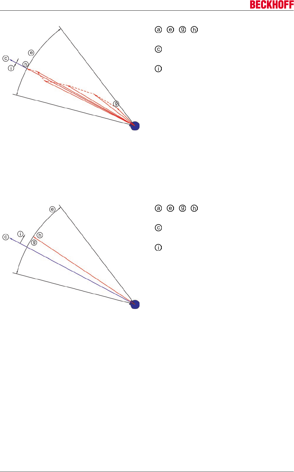
Advanced system characteristics
Servo Drives AX5000208 Version: 2.4
= see IDN P-0-0165 parameter
description above
= flux vector of the rotor with permanent
magnet.
= movement of the rotor
Sequence:
The current vector "g" is developed starting from
the final position of the current vector "a" in Phase
1. Due to the rising magnetic force, the rotor "c" is
turned in the direction of the current vector "g". The
movement is passed through the feedback system
to the AX5000, and supplied to a control loop. This
control loop immediately corrects the direction of
the current vector. This algorithm is executed until
the parameterized current intensity is achieved, and
the current vector approximately coincides with the
flux vector. The current is now maintained over the
period "h" which ensures that optimum
commutation takes place. In this control algorithm,
the rotor only moves minimally through "i".
Variant 2 (IDN-P-0-0165 "Commutation pos control: Kp" = 0 ):
= see IDN P-0-0165 parameter
description above
= flux vector of the rotor with permanent
magnet.
= movement of the rotor
Sequence:
After determining the sector "e" in Phase 1, the
current vector "g" is placed exactly in the center of
the sector "e", and this current is developed. Due to
the rising magnetic force, the rotor "c" is turned in
the direction of the current vector "g" until they
coincide. In this static alignment, the rotor cannot
move more than half the width of the sector "e".
Advanced system characteristics
Servo Drives AX5000 209
Version: 2.4
Using IDN P-0-0165 to affect wake&shake
Parameter Default Possible causes that might require a
change in the default value
First phase current level Stationary current in % Sluggish system,
high attenuation --> increase value
Smooth system,
low attenuation --> reduce value
First phase ramp up time 100ms Sluggish system,
high attenuation --> increase value
Smooth system,
low attenuation --> reduce value
First phase pos monitoring limit 0.5 degrees Application only permits very limited
uncontrolled changes in the movement
--> reduce value
The system has a small amount of
attenuation
--> reduce value
The loading relationships require more
overshoot
--> increase value
First phase step width 22.5 degrees
First phase waiting time after step 150ms Decay behavior of the system:
Long settling time --> increase value
Short settling time --> reduce value
Second phase current level Stationary current in %
Second phase ramp up time 500ms
Second phase duration 3000ms
Error monitoring (range of motion) 90 degrees Application only permits very limited
uncontrolled changes in the movement
--> reduce value
The system has a small amount of
attenuation
--> reduce value
The loading relationships require more
overshoot
--> increase value
Commutation pos control: Kp 0.04 High load stiffness --> increase value
Low load stiffness --> reduce value
A special case "0": Variant 2 is carried out in
Phase 2
10.6.2 Linear motors
The above description of the commutation process applies equally to rotary motors and to linear motors.
Depending on the construction, there are merely some differences of nomenclature (e.g. motor shaft (rotor) =
primary part; "degree" = "mm" (conversion is needed))
WARNING
Warning, risk of injury from uncontrolled movements!
The primary part is moved in steps during "wake&shake". In Phase 1 the maximum electri-
cal movement is 8 x (the value from "P-0-0-0165_Fist phase position monitoring limit"). In
Phase 2it is 0.5 x (the value from "P-0-0-0165_Fist phase step width"). This formula can
only be applied if the previous investigation of stability has been concluded satisfactorily.
Make sure that your application permits this movement, secure the surroundings to prevent
unintentional entry, and make sure that nobody is in the hazardous area.
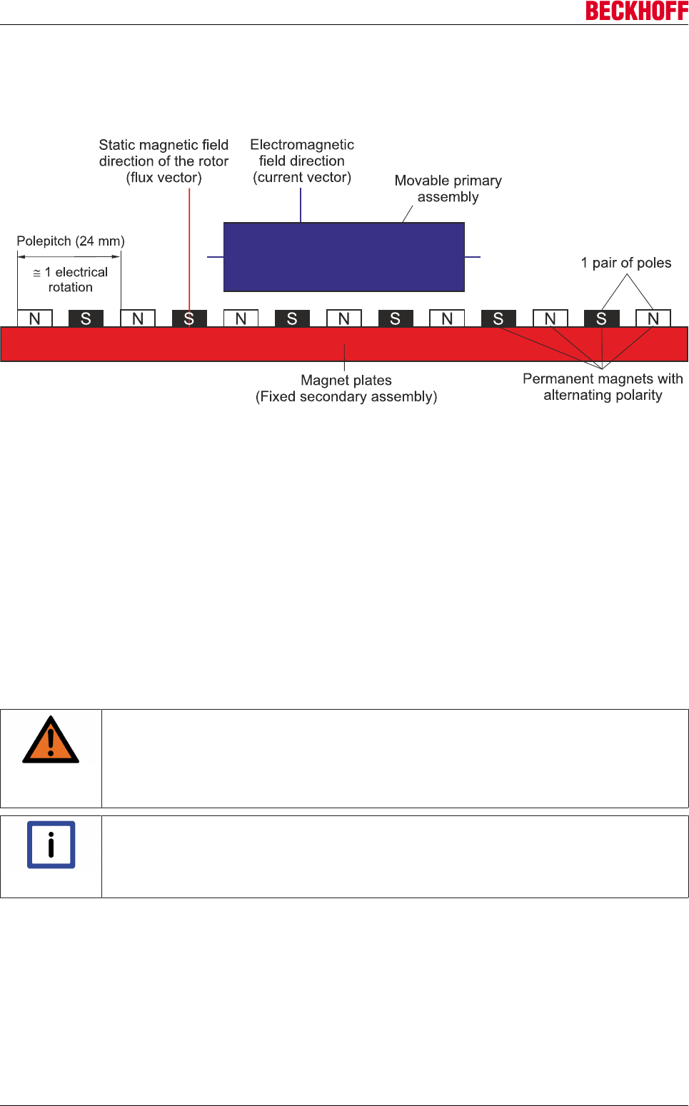
Advanced system characteristics
Servo Drives AX5000210 Version: 2.4
Linear motors consist of a secondary assembly, whose position is fixed, onto which permanent magnets are
attached with alternating polarity and regular spacing. A primary assembly can undergo translatory
movement above this magnetic field. This movement is created by generating an electromagnetic field in the
primary assembly. Linear motors always have only one pair of poles, and the distance between the poles
therefore corresponds to one electrical rotation.
The "Electronic Commutation" section above can be applied to linear motors.
10.6.3 Commutation error "F2A0"
During operation of the motor the commutation is permanently monitored. The following conditions must
apply in order for the AX5000 to detect a commutation error:
1. The current velocity must be higher than the limit speed set in the IDN "P-0-0069 Commutation moni-
toring"
2. The power and acceleration vectors must have different signs.
3. The current power is greater than 95% of the value in the IDN "P-0-0092 Configured channel peak
current".
When these three conditions apply it is very likely that there is a commutation error and that the motor is
undergoing uncontrolled acceleration; the AX5000 generates a commutation error and switches the motor
torque-free i.e. it stops without control.
WARNING
Warning, risk of injury from uncontrolled movements!
A certain distance will have been travelled from the point when the error is detected until
the motor stops. Make sure that your application permits this movement, secure the sur-
roundings to prevent unintentional entry, and make sure that nobody is in the hazardous
area. This applies in particular to vertical axes.
Note
Occurrence of commutation error
A commutation error almost always occurs when the axis is commissioned. If this error oc-
curs during regular operation of the axis then special measures need to be adopted. See
next chapter.
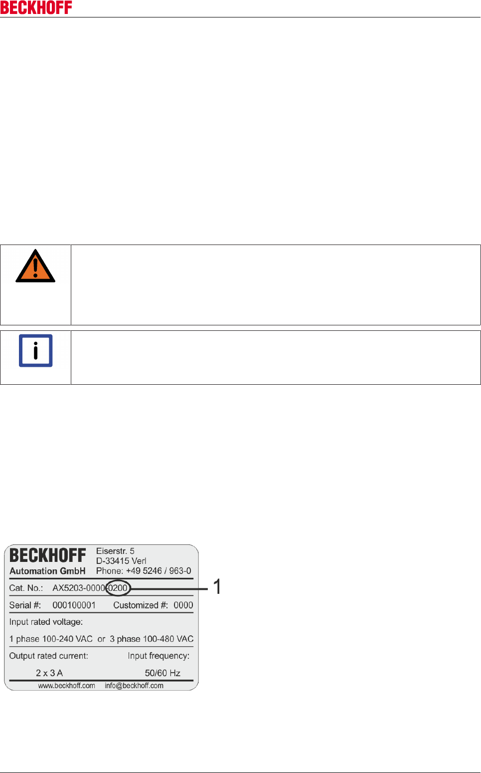
Advanced system characteristics
Servo Drives AX5000 211
Version: 2.4
10.6.4 Commutation error during regular operation (very rare)
Under special operating conditions the regular operation of the axes can fulfil the three conditions cited
above and therefore trigger this error message despite correct commutation. A number of examples are
given below which, however, occur very seldom:
1. When the servo drive is operating at the limit (conditions 1 and 3 are met) and external forces cause
an opposing torque which then fulfils condition 2, the servo drive generates a commutation error.
2. The servo drive is operating at the limit (conditions 1 and 3 are met) and an oscillating current is pro-
duced due to a rapid change of direction or speed. Condition 2 is then also met and a commutation er-
ror arises.
If these examples do not apply to your application, analyze the application and try to find the cause. If you
are unable to remedy the cause but still wish to operate the axis, there is only one option for suppressing the
commutation error:
Parameterize the value of the IDN P-0-0069 to the permitted maximum speed of the motor so that point 1 of
the above-mentioned factors cannot apply and the commutation error will no longer appear.
WARNING
Warning, risk of injury from uncontrolled movements!
Increasing the value of the IDN "P-0-0069" to the highest speed always means that the
commutation monitoring will no longer cause errors, even when other conditions actually
call for this. This is particularly critical when the motor is being replaced. If the value of the
IDN "P-0-0069" is NOT reset, then uncontrolled movements of the motor may occur. Beck-
hoff recommends that you should NOT increase the value of the IDN "P-0-0069".
Note
Drive design
As a rule the drive should not be designed at the limit i.e. the current power should reach a
max. of 90% of the P-0-0092 "Configured channel peak current" value.
10.7 OCT
10.7.1 Precondition for operation
A prerequisite for operation of the OCT motor is a suitable AX5000 with a serial number > 105.000 and
firmware V 2.04 or higher.
AX5000 with hardware version 2
The AX5000 with hardware version 2 is marked
with "0200" (1) in the catalogue number. The
catalogue number can be found on the name
plates.
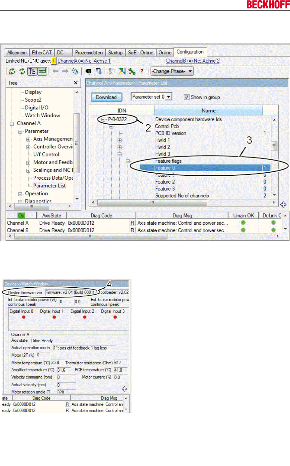
Advanced system characteristics
Servo Drives AX5000212 Version: 2.4
AX5000 with hardware version 2 and set "Featureflag 0"
The feature flags (3) are documented in the IDN "P-0-0322" (2). The "Feature Flag 0" must have the value 1
AX5000 with hardware version 2 and firmware version 2.04 or higher.
The current firmware version of the AX5000 is
displayed under (4) in the "Watch Window".

Advanced system characteristics
Servo Drives AX5000 213
Version: 2.4
10.8 Decommissioning
DANGER
Serious risk of injury through electric shock!
Due to the DC link capacitors, the DC link terminal points "ZK+ and ZK- (DC+ and DC-)"
and "RB+ and RB-" may be subject to dangerous voltages exceeding 875 VDC, even after
the servo drive was disconnected from the mains supply. Wait 5 minutes for the AX5101 –
AX5125 and AX520x; 15 minutes for the AX5140/AX5160/AX5172; 30 minutes for the
AX5190/AX5191; 45 minutes for the AX5192/AX5193 after disconnecting, and measure the
voltage at the DC link terminal points "ZK+ and ZK- (DC+ and DC-)". The device is safe
once the voltage has fallen below 50 V.
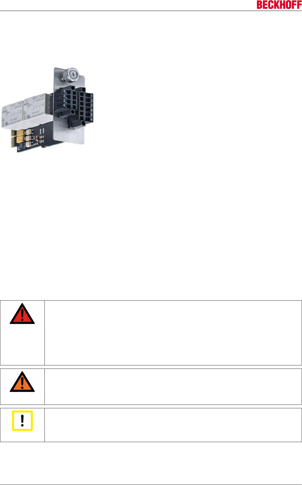
Advanced system characteristics
Servo Drives AX5000214 Version: 2.4
10.9 Integrated safety
10.9.1 Safety-Card AX5801
10.9.2 Intended use
The AX5801 Safety Card is exclusively intended for application in the safety slot of the servo drives AX5101
– AX5140 and AX52xx. The cards are installed together with the servo drive as components in electrical
systems and machinery and may only be used in this way.
10.9.3 Scope of supply
The scope of supply includes the following components:
AX5801 Safety Card, 4-pin connector, 6-pin connector, technical documentation and packaging
If one of the components is damaged please notify the logistics company and Beckhoff Automation GmbH
immediately.
10.9.4 Safety regulations
DANGER
Serious risk of injury through electric shock!
Due to the DC link capacitors, the DC link terminal points "ZK+ and ZK- (DC+ and DC-)"
and "RB+ and RB-" may be subject to dangerous voltages exceeding 875 VDC, even after
the servo drive was disconnected from the mains supply. Wait 5 minutes for the AX5101 –
AX5125 and AX520x; 15 minutes for the AX5140/AX5160/AX5172; 30 minutes for the
AX5190/AX5191; 45 minutes for the AX5192/AX5193 after disconnecting, and measure the
voltage at the DC link terminal points "ZK+ and ZK- (DC+ and DC-)". The device is safe
once the voltage has fallen below 50 V.
WARNING
Caution - Risk of injury!
Electronic equipment is not fail-safe. The machine manufacturer is responsible for ensuring
that the connected motors and the machine are brought into a safe state in the event of a
fault in the drive system.
Attention
Caution – electrostatic charging may lead to destruction of the Safety Card!
The Safety Card is an ESD-sensitive component. Follow the usual ESD safety procedures
when handling the card (anti-static wrist straps, earthing of the relevant components etc.).
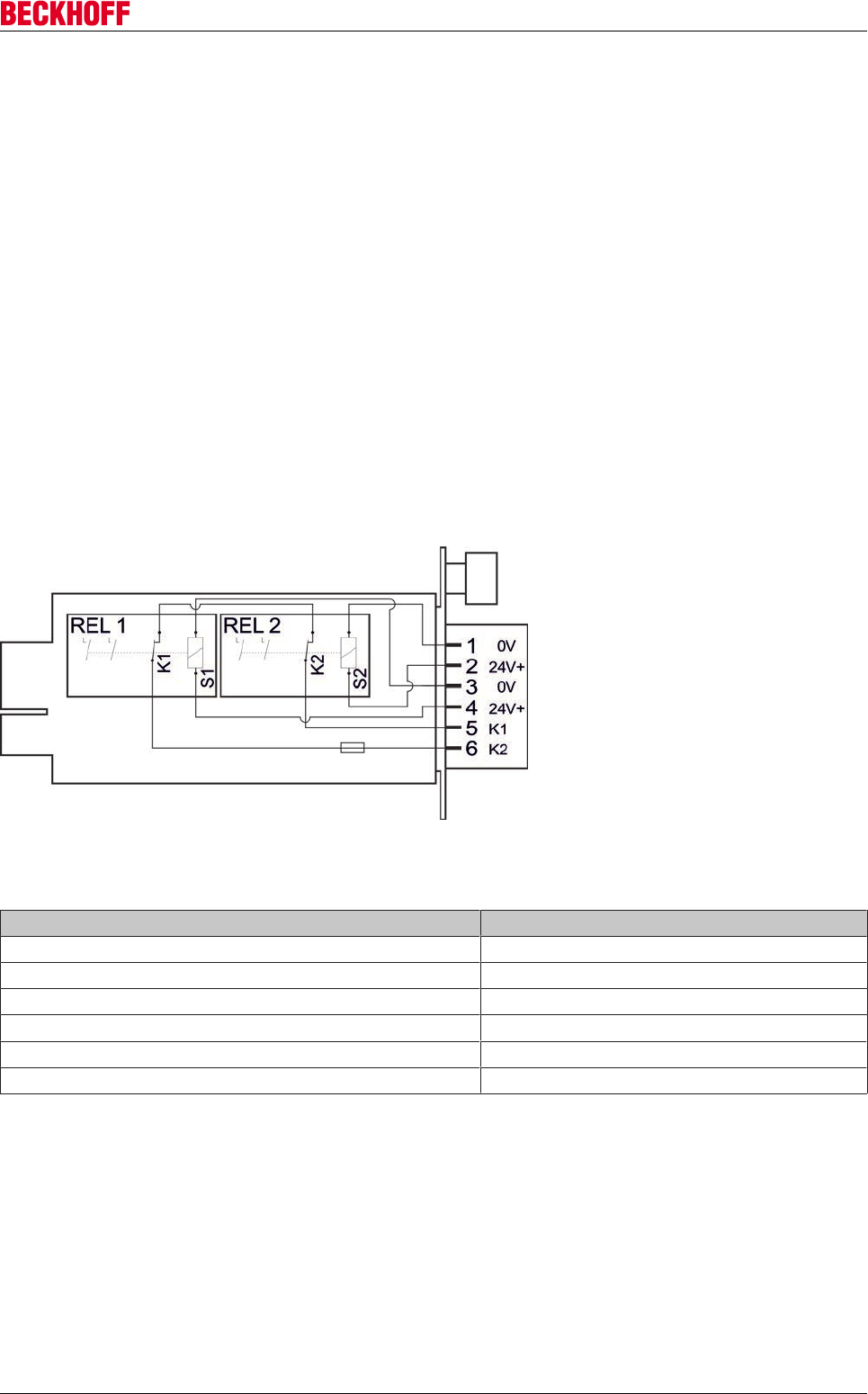
Advanced system characteristics
Servo Drives AX5000 215
Version: 2.4
10.9.5 Personnel qualification
This description is only intended for trained specialists in control, automation and drive engineering who are
familiar with the applicable national standards. Knowledge of machine safety legislation is compulsory.
10.9.6 Product description
The AX5801 Safety Card from Beckhoff is used to realize the safe stop functions "STO or SS1 according to
IEC 61800-5-2". STO stands for SafeTorqueOff, SS1 for SafeStop1.
Thanks to the integrated two-channel monitoring of the AX5000, you can realize stop category 0 or 1
according to IEC 60204-1 with minimum effort and further TwinSAFE blocks from Beckhoff, thereby
achieving category 4, PL e according to ISO 13849-1:2006.
Two-channel monitoring is achieved through certified relays (Rel1 and Rel2). The relays are equipped with
positively driven contacts including feedback contacts (K1 and K2). The feedback contacts are connected in
series and potential-free with terminals (5) and (6) of the 6-pin connector.
The two coils (S1 and S2) have to be supplied with 24 V DC via terminals 1 and 2 or 3 and 4 of the 6-pin or
4-pin connector. Terminals 1-1, 2-2, 3-3 and 4-4 of the two connectors are bridged internally. If a relay
releases, the de-energizing circuit of the AX5000 servo drive range ensures that the connected motors (both
channels) become torque-free.
10.9.7 Technical data
Data Values
Relay operating voltage (terminal 1-4) 24 VDC -15% +20%
Feedback contacts operating voltage (5-6) 24 VDC -15% +20%
Max. switching current of the feedback contacts (5-6) 0.35 A
Conductor cross-section of terminals 1-6 0.2 - 1.5 mm2
Conductor strip length of terminals 1-6 10 mm
Current consumption 50 mA
We recommend using wire end sleeves!
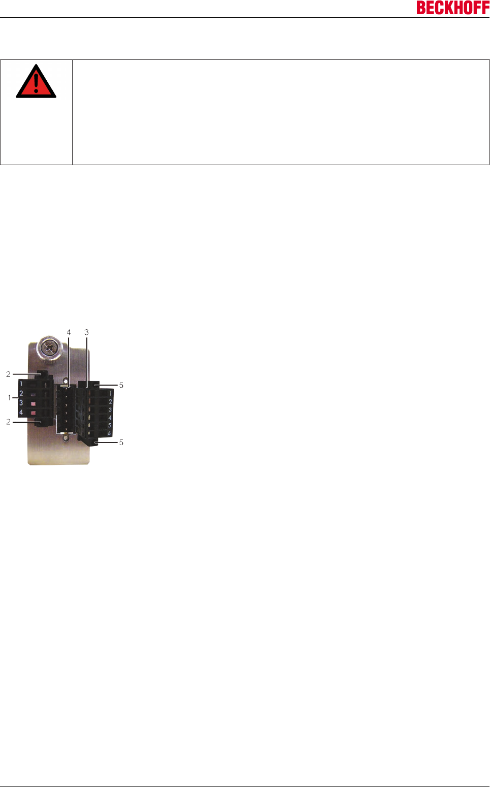
Advanced system characteristics
Servo Drives AX5000216 Version: 2.4
10.9.8 Installation of the AX5801 Safety Card
DANGER
Serious risk of injury!
Due to the DC link capacitors, the DC link terminal points "ZK+ and ZK- (DC+ and DC-)"
and "RB+ and RB-" may be subject to dangerous voltages exceeding 875 VDC, even after
the servo drive was disconnected from the mains supply. Wait 5 minutes for the AX5101 –
AX5125 and AX520x; 15 minutes for the AX5140/AX5160/AX5172; 30 minutes for the
AX5190/AX5191; 45 minutes for the AX5192/AX5193 after disconnecting, and measure the
voltage at the DC link terminal points "ZK+ and ZK- (DC+ and DC-)". The device is safe
once the voltage has fallen below 50 V.
10.9.8.1 Mechanical installation
10.9.8.1.1 Installation of the two connectors on the AX5801 Safety-Card
• Insert the enclosed 4-pin connector (1) into the socket.
• Tighten the two bolts (2).
• Insert the 6-pin connector (3) into the socket.(4).
• Tighten the two bolts (5).
10.9.8.1.2 Installation of the AX5801 Safety-Card
• Fully release the bolt (6).
• Remove the insert (7) in the direction of the arrow (8).
• Carefully insert the Safety Card (9) into the opening in the direction of the arrow (10). The slot has
guides for the card on the short sides.
Ensure that the card is inserted into these guides.
• Tighten the bolt (11).
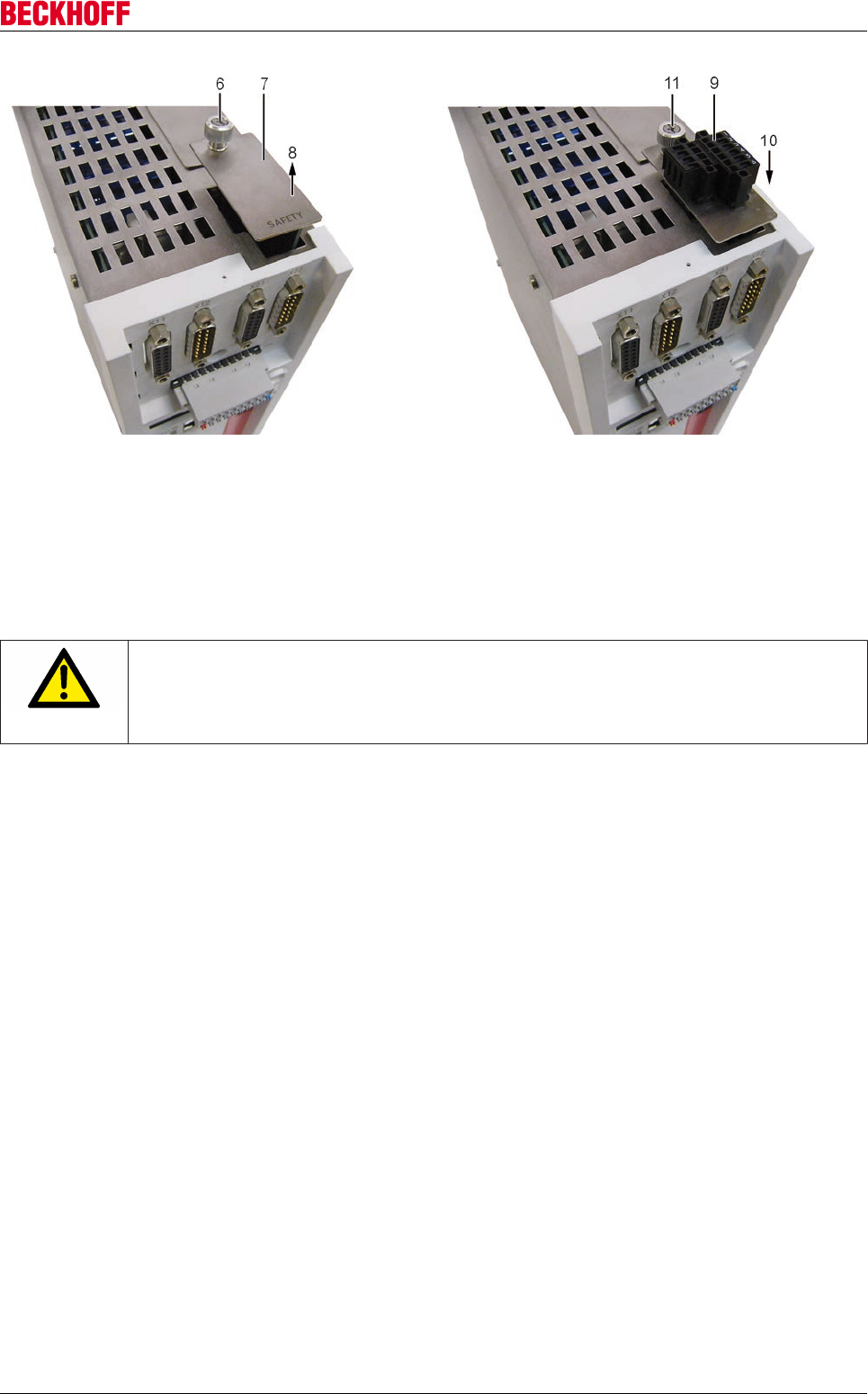
Advanced system characteristics
Servo Drives AX5000 217
Version: 2.4
10.9.8.2 Electrical installation
Configure the safety operation of servo drive via IDN P-0-2000. During the next system start-up the servo
drive automatically detects whether a Safety Card was inserted and whether the IDN P-0-2000
parameterization is correct. Error message "0xFDD4" indicates incorrect configuration. If the servo drive with
the Safety Card does not reach the safe state, error message "0xFDD5" appears on the display of servo
drive. In this case please contact Beckhoff.
CAUTION
Danger for persons and equipment!
If an error message appears on the display of the AX5000 the servo drive must not be put
into service if the servo drive in the system or machine represents a safety-relevant part of
the control system.
10.9.9 Application example (emergency stop – stop category 1)
Components involved:
• Emergency stop device (control switch S1) according to ISO 13850 and control switch S2
• 1 safety input terminal (KL1904) and 1 input terminal (KL 1404)
• 1 safety logic terminal (KL6904) with function block "ESTOP"
• AX5801 Safety Card and servo drive from the AX5000 range
• Programmable logic controller (PLC) and EtherCAT fieldbus
By activating the emergency stop device (S1) inputs EStopIn1 and EStopIn2 of FB "ESTOP" are switched to
state "0", resulting in outputs EStopOut and EStopDelOut of FB "ESTOP" being switched to state "0". As a
result, a quick stop command is issued to the PLC and therefore the AX5000 via EtherCAT. The output
EStopDelOut of FB "ESTOP" ensures that after a specified delay time the 24V supply of the AX5801 Safety
Card is interrupted. This causes the relays (REL1 and REL2) to release and both channels (motors) to be
made torque-free via the internal deactivation procedure of the AX5000.
In the event of a fault the controlled shutdown (quick stop) may fail. The Safety Card becomes active once
the delay time has elapsed, and all motors connected to the device run out. The risk analysis for the machine
must indicate that this behavior can be tolerated. An interlock may be required.
The delay time must be set slightly longer than the maximum braking time of the quick stop.
Sticking relay contacts on the Safety Card are detected via input EDM1 of FB "ESTOP", and restarting is
prevented.
When the emergency stop device is released again, the control switch (S2) must be operated (first rising
then falling edge at the restart input of FB "ESTOP") in order to restart the AX5000.
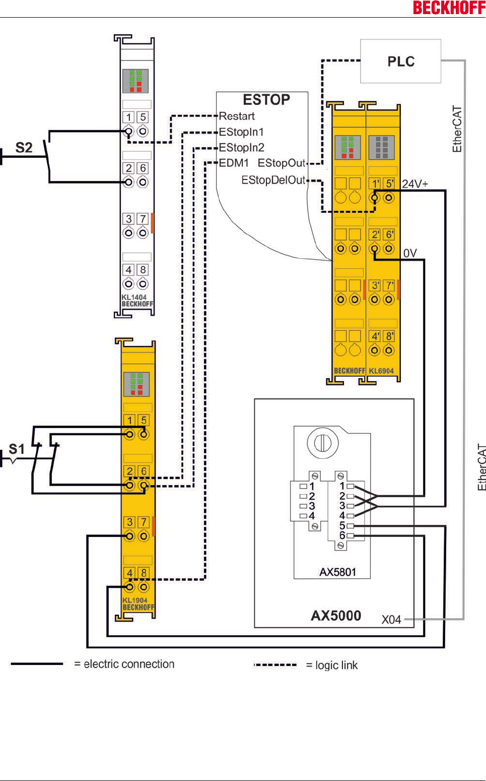
Advanced system characteristics
Servo Drives AX5000218 Version: 2.4
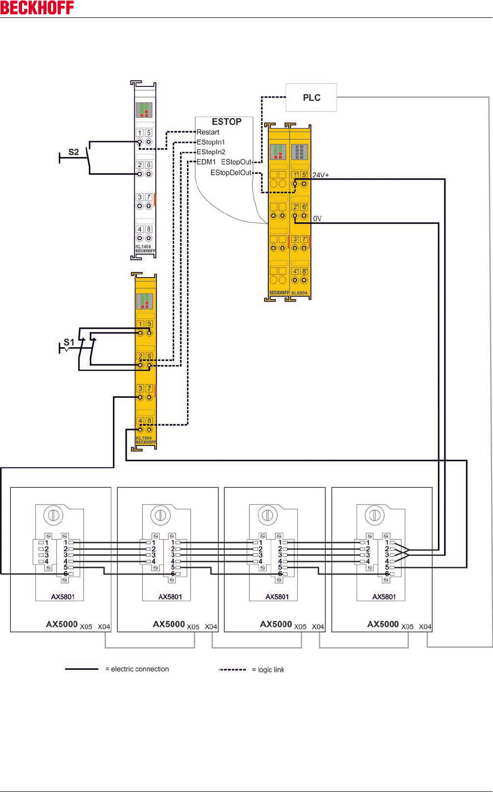
Advanced system characteristics
Servo Drives AX5000 219
Version: 2.4
10.9.10 Application example with several AX5000
Project planning
Servo Drives AX5000220 Version: 2.4
11 Project planning
11.1 Important information for project planning
The more thoroughly a machine or plant project is thought through in advance, the less risk there is of having
to carry out expensive modifications during or after commissioning. This applies to both the mechanical and
electrical design. This chapter can only provide a brief overview of electrical project planning.
11.2 Drive train design
Application, servo drive, motors and gear mechanism must be adapted to each other so that there is an
adequate safety margin for all components as a degree of sluggishness appears over time due to high
temperatures or wear. Make sure that the components in the working area of the system have adequate
reserves so that the working life is not impaired and the necessary control quality can be maintained.
11.3 Energy management
If the quality of the mains supply is impaired due to wide fluctuations in voltage, then both the servo drive
specification and the speed range of the motor will need to be considered. With a positive tolerance for
voltage fluctuation the upper limit value of the wide voltage input of the AX5000 needs to be taken into
account. With a negative tolerance of the voltage fluctuation it must be checked whether the decrease in
speed caused by the low voltage is permissible. With these motors what is known as field weakening
operation (check availability) of the servo drive may provide a solution. If the mains supply does not meet the
specifications for operation of the AX5000, then isolating transformers, mains chokes, mains filters or other
measures may be required.
Note
Only AX5101 – AX5140!
An energy efficient drive system operates in a drive system with a shared DC link and
shared internal and possibly also external brake resistors or brake modules. If you are al-
ready using similar drive systems, the AX5000 offers a convenient diagnostic system for
determining the load on the brake resistors and for transferring the values. Previous experi-
ence with drive systems shows that in such a system much smaller or even no external
brake resistors / brake modules need to be used.
11.4 EMC, earthing, shield connection and potential
Note
EMC information of the servo drive AX5000!
For further information, please read the EMC – information brochure of the servo drive
AX5000. You will find the document on the Beckhoff homepage (www.beckhoff.com) under:
Motion → Documentation → EMC – leaflet.
11.5 Control cabinet
The dimensions of the control cabinet must be sufficient to accommodate all components with the specified
distances. Remember that high temperatures may necessitate forced cooling. Position the control cabinet as
close as possible to the machine so that the motor cables can be as short as possible.
In addition, the control cabinet should have an earthed metal rear panel to which the AX5000 incl. periphery
are attached so that safe earthing can be guaranteed. If you are unable to guarantee these conditions you
need to earth the AX5000 and the relevant components using an approved cable of adequate size.

Accessories
Servo Drives AX5000 221
Version: 2.4
12 Accessories
Accessories with UL-Listing!
If you wish to operate an AX5000 in an economic area that requires a UL-Listing, please
make sure that the accessories also have a UL-Listing.
The following optional accessories are available (see Beckhoff main catalog or www.beckhoff.de):
• Motor and feedback cable (ready-made )
• Motor and feedback cable sold by the metre
• D-Sub connector X11, X12, X21, X22 individual (for feedback cable and resolver/Hall)
• Motor and sensor connector X13, X14, X23, X24
• EtherCAT bus cable, ready-made or sold by the metre
• Synchronous servomotors (linear or rotational)
• External ballast resistor
• Expansion cards
• Additional modules
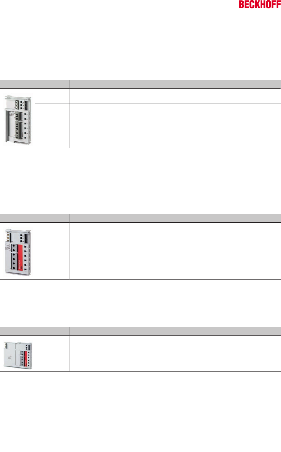
Accessories
Servo Drives AX5000222 Version: 2.4
12.1 AX-Bridge - quick connection system
12.1.1 Supply module for multi-axis system
If several AX5000 are to be linked to form a multi-axis system, a supply module for connecting the mains
voltage and the control voltage (24 VDC) for the control electronics and the motor brake is required.
Figure Article no. Description
AX5901 AX-Bridge power supply module for connection of supply voltage and 24 V DC
for control and brake energy (pluggable), for AX5x01…AX5125, 85 A
AX5902 AX-Bridge power supply module for connection of supply voltage and 24 V DC
for control and brake energy (pluggable), for AX5140, 85 A
To install the supply module connectors X01, X02 and X03 must be removed and replaced with the supply
module.
12.1.2 AX-Bridge connection module (AX5x01 - AX5112)
The connection between the two AX amplifiers is established by moving the three busbar sliders of the first
connection module of the next drive to the left.
Figure Article no. Description
AX5911 AX-Bridge power distribution module, quick connection system for power supply,
DC-Link and control voltage (pluggable), for AX5x01…AX5112, 85 A
12.1.3 AX-Bridge connection module (AX5118 and AX5125)
The connection between the two AX amplifiers is established by moving the three busbar sliders of the first
connection module of the next drive to the left.
Figure Article no. Description
AX5912 AX-Bridge power distribution module, quick connection system for power supply,
DC-Link and control voltage (pluggable), for AX5118 and AX5125, 85 A
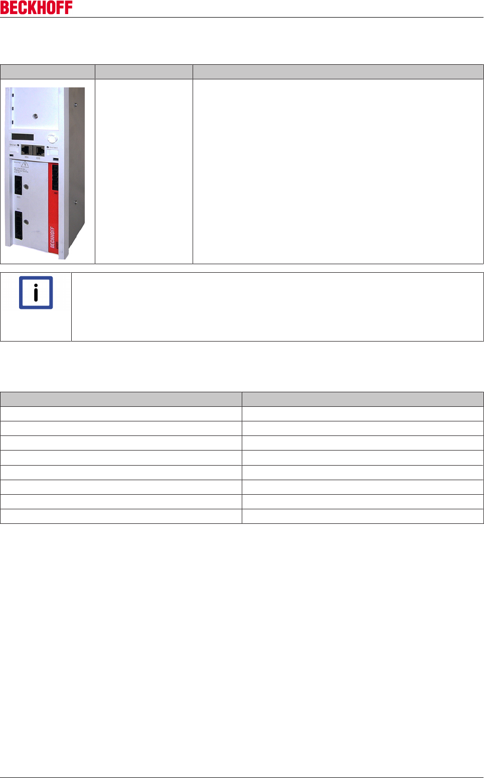
Accessories
Servo Drives AX5000 223
Version: 2.4
12.2 Brake module - AX5021-0000
Figure Art.-No. Description
AX5021-0000-0000 Using a brake module it is possible to take up additional braking
power in a drive system, because the connection of an external
brake resistor without a brake module in a drive system with
devices up to max. 25 A rated current is not permissible. A
further advantage is the simple installation and the small space
requirement of the brake module. The brake module is equipped
with a complete DC link and an internal brake resistor and
enables the connection of an external brake resistor with the
integrated brake chopper. Several brake modules can be
integrated into a drive system.
Note
Operating conditions
The brake module may only be used together with servo drives of the AX51xx-xxxx-02xx or
AX52xx-xxxx-02xx series. These devices have serial numbers above 100.000. In addition
to the AX5021, the drive system must include at least two further servo drives from the
AX5000 range.
12.2.1 Electrical data
Electrcal data AX5021
int. Resistance1) [W] 150
int. Resistance2) [W] 14.000
ext. Resistance min. [Ω] 22
ext. Resistance3) [W] 6.000
ext. Resistance4) [W] max. 32.000
Power loss P [W] max. 250
Charging rate 24 VDC [A] 0.3 – 0.4
DC link capacity [µF] 705
1) Durability break power Prms
2) Peak break power Ppeak
3) Durability brake power Prms
4) Peak brake power Ppeak
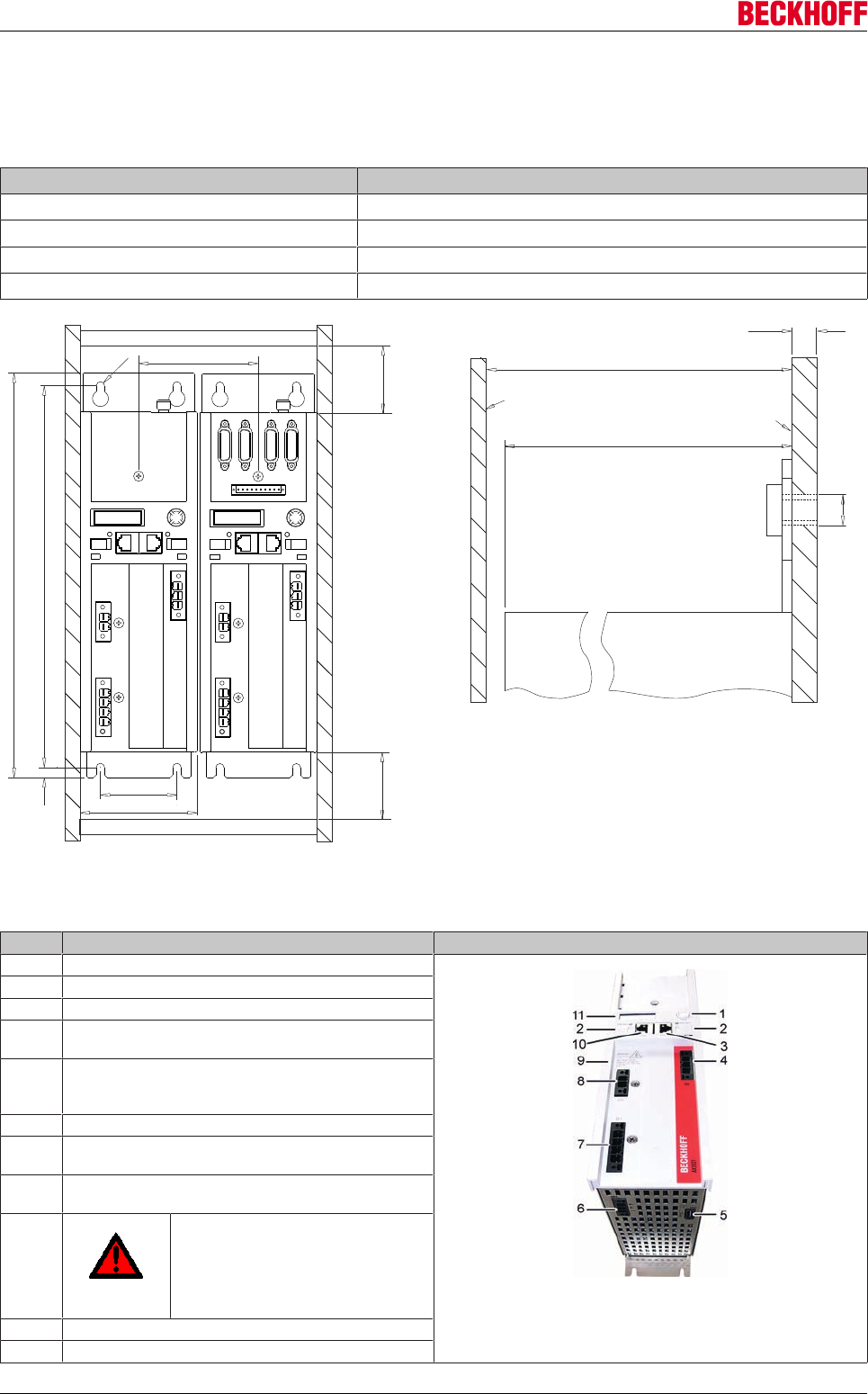
Accessories
Servo Drives AX5000224 Version: 2.4
12.2.2 Mechanical data
The external dimensions of the brake module are identical to the dimensions of the servo drives from the
AX5000 series up to 12 A.
Mechanical data AX5021
Weight approx. 4 kg
Width 92 mm
Height without plugs 274 mm
Depth without connectors / accessories 232 mm
299.2
60
AX5021 AX5206
93
8
Min. 100
Min.100
92
317.2
6.5
>2,5
M6
>277,6
277,6
AX5021
Control cabinet door Mounting plate
contuctible (zinced)
(Incl. plug and cable for feedback)
Cable duct
Cable duct
12.2.3 General overview
No. Name
1 Navigation rocker
2 Labelling field
3 X05 - socket for EtherCAT output
4 X03 – power supply 24 V DC
Input
5 X52 - connection of the temperature monitor
and the fan of the
external brake resistor
6 X51 - connection of the external brake resistor
7 X01 – mains supply
100 – 480 V
8 X02 – DC link output
(890 V DC voltage).
9
DANGER
Max. voltage 890 V DC at the DC link
terminals (X02). Once the device has
been switched off dangerous voltage
will still be present for a further 5 min-
utes. The device is safe once the volt-
age has fallen below 50 V.
10 X04 - socket for EtherCAT input
11 Display
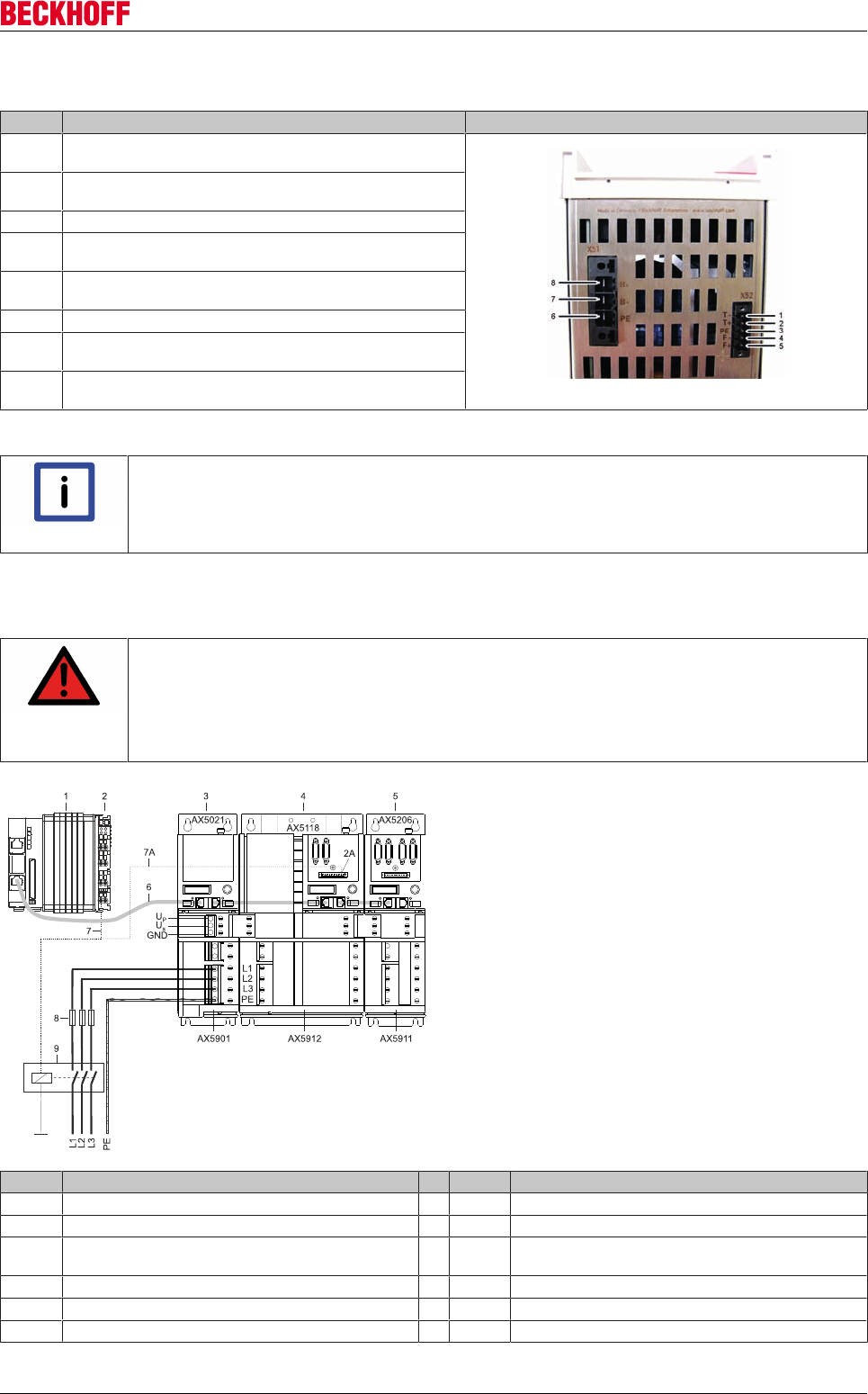
Accessories
Servo Drives AX5000 225
Version: 2.4
12.2.4 Pin strip assignment of X51 and X52
No. Name
1T- = input of the temperature measurement sensor of the ex-
ternal brake resistor
2T+ = input of the temperature measurement sensor of the ex-
ternal brake resistor
3PE = protective conductor
4F- = output to the fan controller
of the external brake resistor
5F+ = output to the fan controller
of the external brake resistor
6PE = protective conductor
7B- = output to the controller of
the external brake resistor
8B+ = output to the controller of
the external brake resistor
Please refer to the servo drive ‘Startup’ manual for the pin assignments of the remaining inputs and outputs.
Note
Temperature rise in the external brake resistor
The temperature rise of the external brake resistor should be monitored continuously via
temperature contacts (1) and (2).
12.2.5 Electrical connection (example)
DANGER
Serious risk of injury through high electrical voltage!
Due to the DC link capacitors dangerous voltage may persist at the DC link contacts "X02"
after the servo drive has been disconnected from the mains supply. Wait 5 minutes after
disconnection and measure the voltage on the DC link contacts DC+ and DC-. The device
is safe once the voltage has fallen below 50 V.
The example below describes the brake module and several servo
drives, which are linked via AX-Bridge modules to make up a drive
system. We recommend that the brake module be placed in the
first position with the AX-Bridge power supply module (AX5901)
and after that the servo drives with decreasing rated current; we
assume here that the most powerful servo drive also releases the
greatest brake energy.
CAUTION!
Uncontrolled movements!
If the drive system is disconnected from the mains due to a mains
failure, all axes of the drive system make uncontrolled movements.
Take suitable measures to ensure than no persons are endan-
gered during this time. Vertical axes are particularly dangerous.
Pos. Name Pos. Name
1 PC with TwinCAT and PLC 6 Patch cable
2 Output terminal 7 Control cable from the output terminal
2A Output "8" of the servo drive digital I/Os 7A Control cable from output ‘8’ of the servo drive digital I/
Os
3 Brake module 8 Mains fuses
4 Servo drive (with the greatest brake energy) 9 Mains contactor
5 Servo Drives
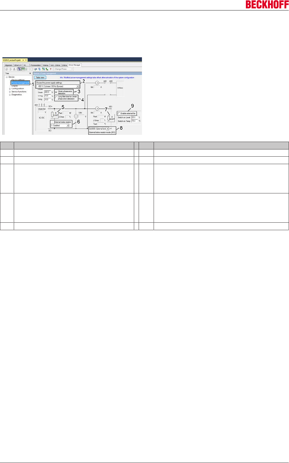
Accessories
Servo Drives AX5000226 Version: 2.4
12.2.6 Integration into TwinCAT
Integration of the brake module by TCDriveManager and Powermanagement
The brake module can be integrated and
parameterized in the TCDriveManager as a
completely digital I/O device.
The position descriptions are in the table below.
Pos. Description Pos.
1 Powermanagement 6 Activation / deactivation of the internal brake resistor
2 Mains voltage selection 7 External brake resistor parameter list
3 Phase monitoring (deactivate for single-phase mains) 8 0 = Deactivation of the external brake resistor
(not recommended)
1 = Standard energy management with external brake resistor
2 = Energy management with external brake resistor
(standalone)
4 Delay time until the phase monitoring responds
(activate if mains is unclean)
9 Enabling / disabling the fan of the external brake resistor and
setting the switching thresholds Switch on Level: Percentage
specification of the rated capacity value of the external brake
resistor. Switch on Temp.: Max. temperature value for the
external brake resistor in °C.
5 Internal brake resistor parameter list
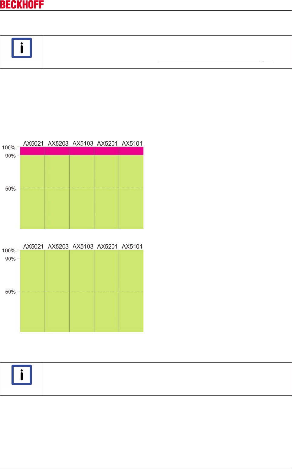
Accessories
Servo Drives AX5000 227
Version: 2.4
12.2.7 DC link (only for 60A-170A devices)
Note
Connection example DC link group!
For further information of the production for an DC link group you will find in the system
manual of the servo drive AX5000 under: "Connection example – DC link group [}50]"
12.2.8 Operation modes of the AX5021
It can be assumed that a brake module is used only if the brake energy cannot be dissipated despite a DC link system and internal
brake resistors. The brake module can be operated in two different operation modes, which have a direct influence on the energy man-
agement. The operation modes can be selected when using the external brake resistor. The following sketches show the storage ca-
pacity of the DC link of the individual devices in relation to the operation modes.
Ext. brake resistor enabled (system / standard)
In this operation mode the capacity of the DC link of the brake
module is reduced by approx. 10%. At 90% DC link load the brake
chopper then directs the generated braking energy to the external
brake resistor and, when this has reached its capacity limit, into the
internal brake resistor. In this case the brake energy is first fed into
the brake module, since the brake choppers in the other servo
drives are only activated at 100% utilization of the DC link. This op-
eration mode is set as the default, because no further configuration
of the devices in the DC link system is necessary apart from the
basic configuration of the brake module. If the external brake resis-
tor of the brake module is mounted outside the control cabinet,
then the thermal load in the control cabinet is also lower.
Ext. brake resistor enabled (standalone brake chopper)
In this case the capacity of the DC links is fully utilized. This opera-
tion mode must be selected and, apart from the basic configuration
of the brake module, the internal brake resistors of the devices in
the DC link system should be deactivated, as otherwise the ther-
mal load in the control cabinet will also increase. In order to reduce
the thermal load further, it is a good idea to mount an external
brake resistor on the brake module outside the control cabinet.
12.2.9 Braking power diagnosis
Note
Power Management of the servo drive AX5000!
Further information for the diagnostics of the external brake resistors you will find in the
function description of the servo drive AX5000 under: “Power Management”.
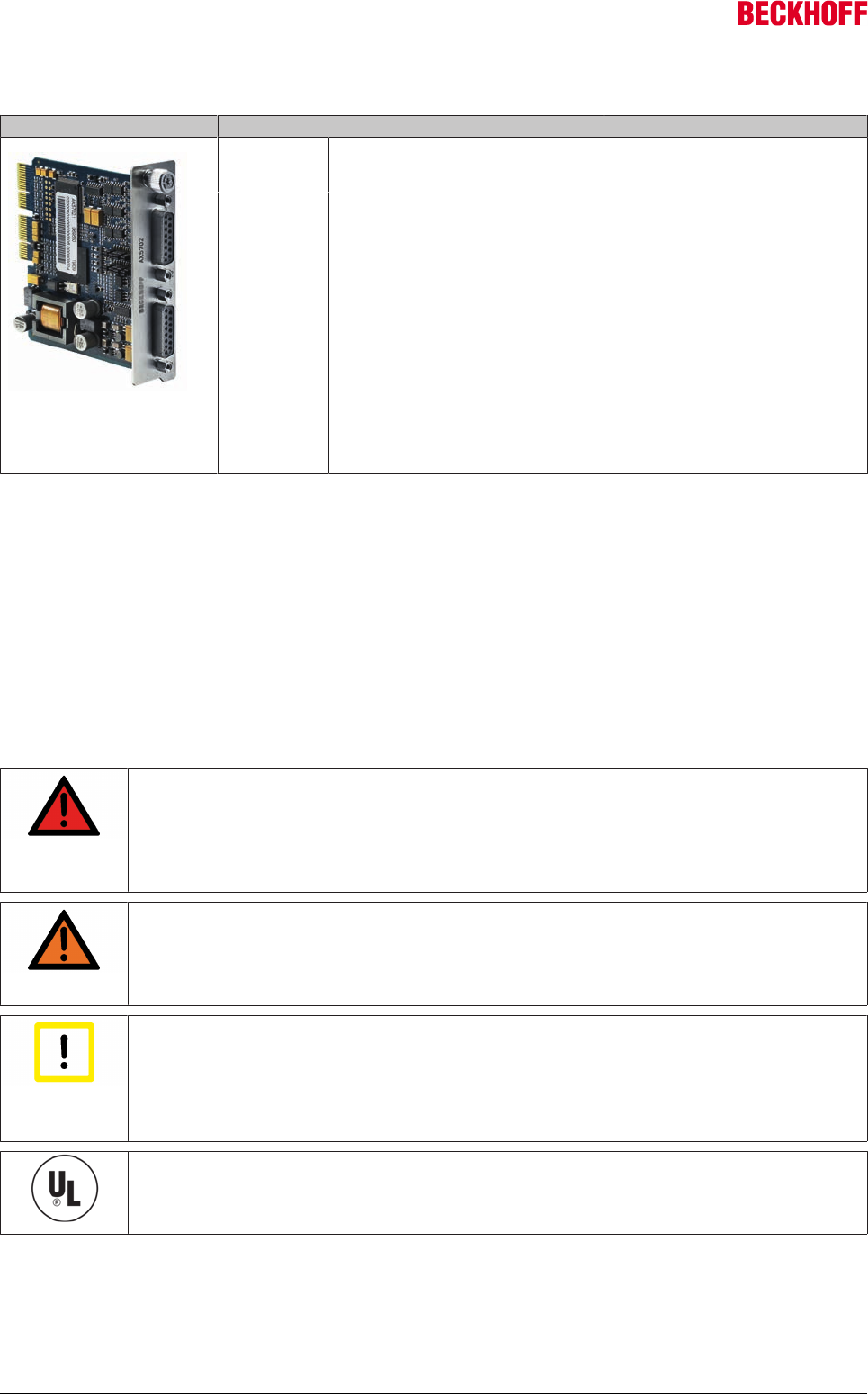
Accessories
Servo Drives AX5000228 Version: 2.4
12.3 Optional encoder card - AX5701 / AX5702
Figure Art.-No. Description
AX5701-0000 encoder option card for one additional
encoder input 1 Vpp, BiSS B, Hiperface,
EnDat
The optional encoder card enables con-
nection of an additional feedback sys-
tems per channel. The system parame-
ters match the standard parameters that
are analyzed via inputs X11 and X21.
Through simple configuration via
jumpers up to six further digital inputs
(In "A" to In "F") can be analyzed, which
are provided through special feedback
systems via parameter channels. The
X41 and X42 sockets are compatible
with the plugs of the X11 and X21 front
sockets of the AX5000, which means
that the tried and tested cables from the
ZK4510 series can be used. To analyze
the additional digital inputs you simply
have to insert an adapter or establish a
suitable wiring. This optional card can-
not be used as commutation feedback
system (primary).
AX5702-0000 encoder option card for two additional
encoder inputs 1 Vpp, BiSS B, Hiperface,
EnDat
12.3.1 Intended use
The optional encoder cards are exclusively intended for application in the optional rear slot of a servo drive
from the AX5000 series. The cards are installed together with the servo drive as components in electrical
systems and machinery and may only be used in this way.
12.3.2 Safety regulations
The responsible staff must ensure that the application or use of the products described satisfy all the
requirements for safety, including all the relevant laws, regulations and guidelines.
DANGER
Caution - Danger of death!
Even when the AX5000 is disconnected from the mains voltage, dangerous voltage contin-
ues to be present at the "X02" terminals of the DC link for at least 5 minutes. Wait until the
DC link capacitors are discharged before touching live terminals. The voltage measured be-
tween the DC+ and DC- terminals (X02) must have dropped to below 50 V.
WARNING
Caution - Risk of injury!
Electronic equipment is not fail-safe. The machine manufacturer is responsible for ensuring
that the connected motors and the machine are brought into a safe state in the event of a
fault in the drive system.
Attention
Caution – Destruction of the optional encoder card through electrostatic
charging!
The optional encoder card is an ESD-sensitive component. Follow the usual ESD safety
procedures when handling the card (anti-static wrist straps, earthing of the relevant compo-
nents etc.).
UL approval
If you intend to operate an AX5000 in a region that requires UL approval, please refer to
the chapter "Guidelines and Standards".
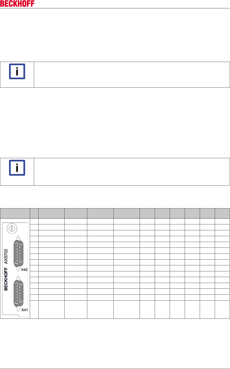
Accessories
Servo Drives AX5000 229
Version: 2.4
12.3.3 Product identification
12.3.3.1 Type key
AX5701 – optional encoder card for single-channel servo drives
AX5702 – optional encoder card for two-channel servo drives
Note
Operation of the optional encoder card
The AX5701 can only be used in single-channel servo drives, the AX5702 can only be used
in two-channel servo drives.
Inputs A to D are single-wire inputs (single-ended). They have a certain potential to ground, which is
analysed.
Inputs E to F are two-wire inputs (differential). Thy require (+) and (-) and analyse the voltage difference
between the conductions.
Firmware revision
AX5000-xxxx-02xx = mind. 2.03 build 0009
12.3.3.2 Description of the digital inputs
Note
Configuration of the digital inputs and outputs!
Further information on the control and configuration of the digital inputs and outputs can be
found in the function description of the servo drive AX5000 under: "Digital Inputs and Out-
puts".
12.3.3.3 Overview of sockets X41 (channel A) and X42 (channel B)
Pin EnDAT /
BiSS
Hiperface Sin / Cos 1Vpp TTL1) In "A" In "B" In "C" In "D" In "E" In "F"
1 SIN + SIN + SIN + n.c. X X (+)
2 GND_5 V GND_9 V GND_5 V GND_5 V
3 COS + COS + COS + n.c. X X (+)
4 Us_5 V n.c. Us_5 V Us_5 V
5 DX+ (Data) DX+ (Data) n.c. B+ Y
6 n.c. Us_9 V n.c. n.c.
7 n.c. n.c. REF Z REF Z
8 CLK+ (Clock) n.c. n.c. A+ Y
9 REF SIN REF SIN REF SIN n.c. X X (-)
10 GND_Sense n.c. n.c. GND_Sense
11 REF COS REF COS REF COS n.c. X X (-)
12 Us_5 V Sense n.c. Us_5 V Sense Us_5 V Sense
13 DX - (Data) DX - (Data) n.c. n.c. Y
14 n.c. n.c. Z + Z +
15 CLK - (Clock) n.c. n.c. n.c. Y
1)Attention: Wire break detection is not supported for TTL encoders.
The digital inputs "A" to "D" can be connected to X or Y.
The digital inputs "E" and "F" must be connected to X (+) and X (-).
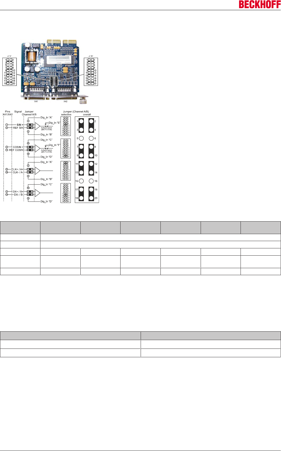
Accessories
Servo Drives AX5000230 Version: 2.4
12.3.3.4 Configuration of jumpers J-"A" for channel "A" and J-"B" for channel "B"
Jumpers J-"A" and J-"B" (1) are located at the center of the printed circuit
board near the front panel of the card. For each channel there are 2 row of
jumpers, each with 20 pins. The default setting without analysis of the addi-
tional inputs is shown in the following figure.
The opposite figure shows the basic jumper configuration, which is the same
for channel A and channel B. The pins of input sockets X41 and X42 are
wired firmly to the corresponding pins of the jumpers rows. The non-config-
urable pins are not shown. To use the additional inputs proceed as follows:
• Reposition the relevant jumpers und set IDNP-0-0180-->Feedback
options-->Digital Inputs "Input A" to "Input D" to "used" or set
IDNP-0-0180-->Feedback options-->Digital Inputs "Input E" or "Input
F" to "used" without repositioning the jumpers.
• Connect the encoder cable as required for the relevant inputs or use
an adapter.
The following table shows a selection of combination options.
Feedback sys-
tem
Input "A" Input "B" Input "C" Input "D" Input "E" Input "F"
EnDat not available
BiSS not available
Hiperface X X
Sin / Cos
1 Vpp
XXXX
TTL1) X2) X2) X3) X3) X2) X3)
1)Attention: Wire break detection is not supported for TTL encoders.
2) Either inputs "A" and "B" or input "E" can be used
3) Either inputs "C" and "D" or input "F" can be used.
12.3.3.4.1 Technical data
Description Value
Digital inputs "A" to "D" (single-ended) Open collector with max. 1 mA
Digital inputs "E" to "F" (differential) 0 - 5 V at the input resistance 120 W
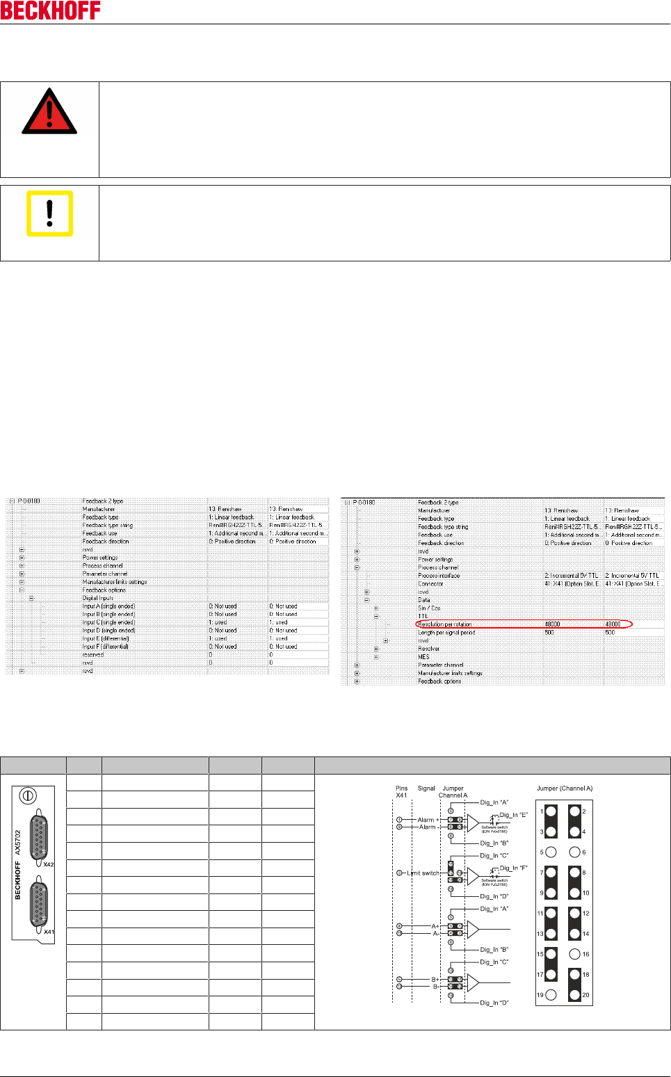
Accessories
Servo Drives AX5000 231
Version: 2.4
12.3.4 Installation of the optional encoder card
DANGER
Caution - Danger of death!
Even when the AX5000 is disconnected from the mains voltage, dangerous voltage contin-
ues to be present at the "X02" terminals of the DC link for at least 5 minutes. Wait until the
DC link capacitors are discharged before touching live terminals. The voltage measured be-
tween the DC+ and DC- terminals (X02) must have dropped to below 50 V.
Attention
Destruction of the optional encoder card through electrostatic charging!
The optional encoder card is an ESD-sensitive component. Follow the usual ESD safety
procedures when handling the card.
• Fully release the screw (1).
• Remove the panel (2).
• Carefully insert the optional card (3) into the
opening in the direction of the arrow. The slot
has guides for the card on the short sides.
Ensure that the card is inserted into these
guides. Tighten the bolt (4).
12.3.5 Sample: Renishaw RGH 22Z30D00
Feedback and inputs Scaling
12.3.5.1 Overview of socket X41 (channel A) and jumper configuration
Socket X41 Pin Renishaw In "C" In "E" Jumper configuration
1 Alarm + X +
2 GND_5 V
3 Limit switch X
4 Us_5 V
5 B +
6 n.c.
7 REF Z
8 A +
9 Alarm - X -
10 GND_Sense
11 n.c.
12 Us_5 V Sense
13 B -
14 Z +
15 A -
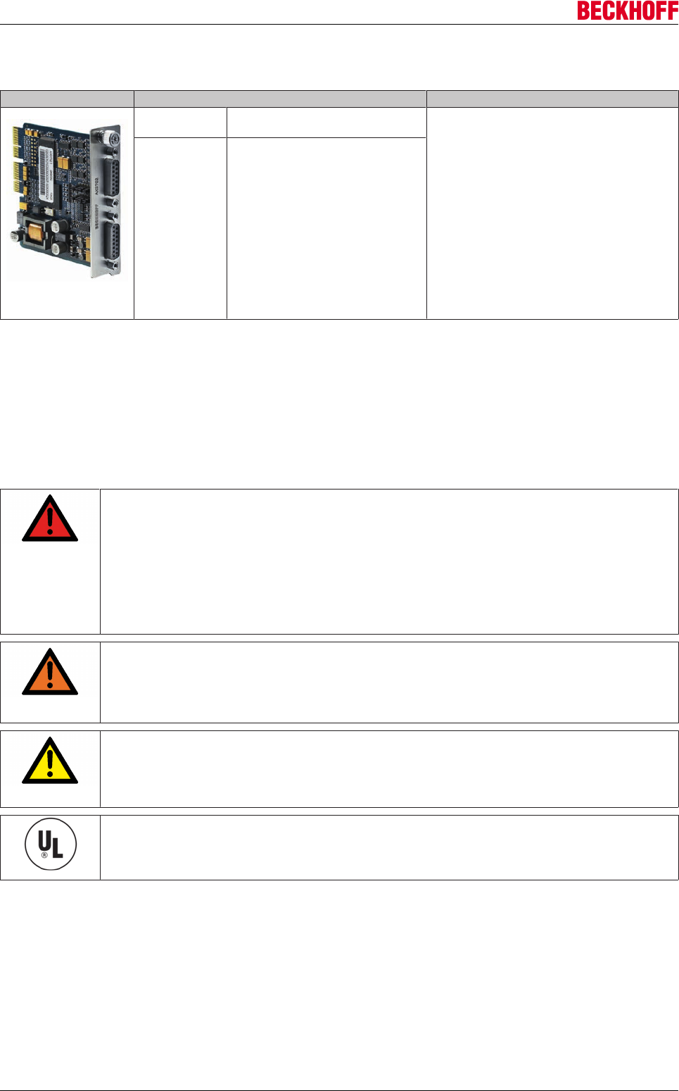
Accessories
Servo Drives AX5000232 Version: 2.4
12.4 Optional encoder card - AX5721 / AX5722
Figure Art.-No. Description
AX5721-0000 encoder option card for one additional
encoder input EnDat 2.2, BiSS C
The optional encoder card enables connection of
an additional feedback systems per channel. The
system parameters match the standard parame-
ters that are analyzed via inputs X11 and X21.
Through simple configuration via jumpers up to
six further digital inputs (In "A" to In "F") can be
analyzed, which are provided through special
feedback systems via parameter channels. The
X41 and X42 sockets are compatible with the
plugs of the X11 and X21 front sockets of the
AX5000, which means that the tried and tested
cables from the ZK4510 series can be used. To
analyze the additional digital inputs you simply
have to insert an adapter or establish a suitable
wiring. This optional card cannot be used as
commutation feedback system (primary).
AX5722-0000 encoder option card for two additional
encoder inputs EnDat 2.2, BiSS C
12.4.1 Intended use
12.4.2 Safety regulations
The responsible staff must ensure that the application or use of the products described satisfy all the
requirements for safety, including all the relevant laws, regulations and guidelines.
DANGER
Danger of death!
Due to the DC link capacitors dangerous voltage (> 875VDC) may persist at the DC link con-
tacts “ZK+ and ZK- (DC+ and DC-)“ and “RB+ and RB-“ after the servo drive has been dis-
connected from the mains supply. After disconnecting the servo drive wait at AX5101 -
AX5125 and AX520x; 5 minutes, at AX5140/AX5160/AX5172; 15 minutes, at AX5190/
AX5191; 30 minutes and at AX5192/AX5193; 45 minutes and measure the voltage at the
DC link contacts ZK+ and ZK- (DC+ and DC-). The device is safe once the voltage has
fallen below 50 V.
WARNING
Warning – Risk of injury!
Electronic equipment is not fail-safe. The machine manufacturer is responsible for ensuring
that the connected motors and the machine are brought into safe state in the event of a
fault in the drive system.
CAUTION
Destruction of the digital encoder card through electrostatic charging!
The digital encoder card is an ESD-sensitive component. Follow the usual ESD safety pro-
cedures when handling the card.
UL approval
If you intend to operate an AX5000 in a region that requires UL approval, please refer to
the chapter "Guidelines and Standards".
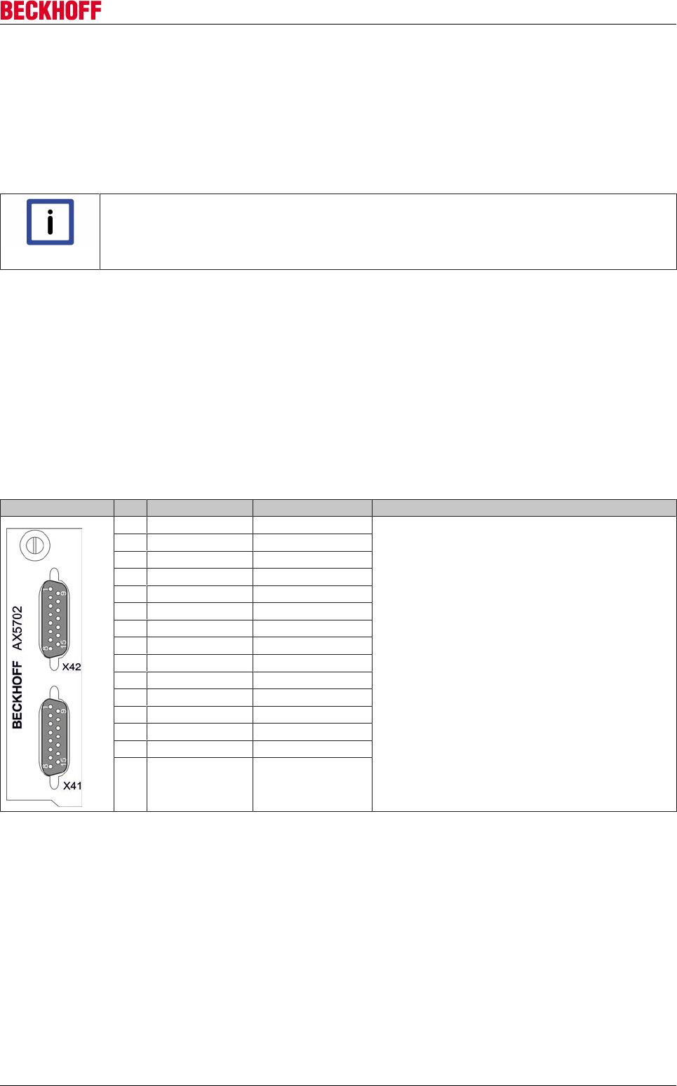
Accessories
Servo Drives AX5000 233
Version: 2.4
12.4.3 Product identification
12.4.3.1 Type key
AX5721 – High Resolution Digital Encoder Option Card for single-channel servo drives.
AX5722 – High Resolution Digital Encoder Option Card for dual-channel servo drives.
Note
No safety functions!
Safety functions cannot be implemented with the encoder option card.
The encoder option card enables the connection of one digital feedback system per channel. The sockets
X41 or X42 respectively are not plug-compatible with the front sockets X11 or X21 respectively of the
AX5000. The following interfaces are supported:
• EnDat 2.2
• BiSS “C” mode
Firmware revision:
AX5000: 2.06 or higher and AX572x: 2.06 or higher.
12.4.3.2 Overview of sockets X41 (channel A) and X42 (channel B)
Pin EnDat 2.2 BiSS C Output current
1 n.c. n.c. 0.25 A / Channel
2 GND GND
3 n.c. n.c.
4 5V+ ±10% 5V+ ±10%
5 Data+ Data+
6 12V 12V
7 n.c. n.c.
8 CLK+ CLK+
9 n.c. n.c.
10 GND sense GND sense
11 n.c. n.c.
12 5V sense ±10% 5V sense ±10%
13 Data- Data-
14 n.c. n.c.
15 CLK- CLK-
1)Attention: Wire break detection is not supported for TTL encoders.
The digital inputs "A" to "D" can be connected to X or Y.
The digital inputs "E" and "F" must be connected to X (+) and X (-).
12.4.3.2.1 Technical data
Max. single turn resolution: 32 bit
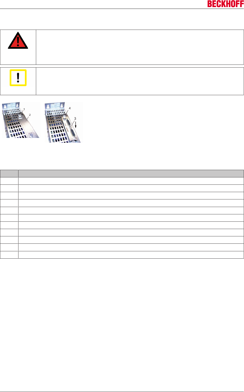
Accessories
Servo Drives AX5000234 Version: 2.4
12.4.4 Installation of the optional encoder card
DANGER
Caution - Danger of death!
Even when the AX5000 is disconnected from the mains voltage, dangerous voltage contin-
ues to be present at the "X02" terminals of the DC link for at least 5 minutes. Wait until the
DC link capacitors are discharged before touching live terminals. The voltage measured be-
tween the DC+ and DC- terminals (X02) must have dropped to below 50 V.
Attention
Destruction of the optional encoder card through electrostatic charging!
The optional encoder card is an ESD-sensitive component. Follow the usual ESD safety
procedures when handling the card.
• Fully release the screw (1).
• Remove the panel (2).
• Carefully insert the optional card (3) into the
opening in the direction of the arrow. The slot
has guides for the card on the short sides.
Ensure that the card is inserted into these
guides. Tighten the bolt (4).
12.4.5 Error messages
No. Description
F870 „Encoder not ready“ – execute the RESET command (S-0-0099)
F872 „Error flag active“ – status changes to „Safe-Op“. Restart required.
F873 „Get position timeout“ – status changes to „Safe-Op“. Restart required.
F874 “Crc memory error”– execute the RESET command (S-0-0099)
F875 “No EnDat 2.2 encoder connected”– execute the RESET command (S-0-0099)
F876 “UART Error”– execute the RESET command (S-0-0099)
F877 “Out of memory”– execute the RESET command (S-0-0099)
F879 “Callibration error”– execute the RESET command (S-0-0099)
F87A “AX572x power supply error”– execute the RESET command (S-0-0099)
F87C “AX572x protocol not supported”– execute the RESET command (S-0-0099)
F87D “AX572x wrong parameter”– execute the RESET command (S-0-0099)
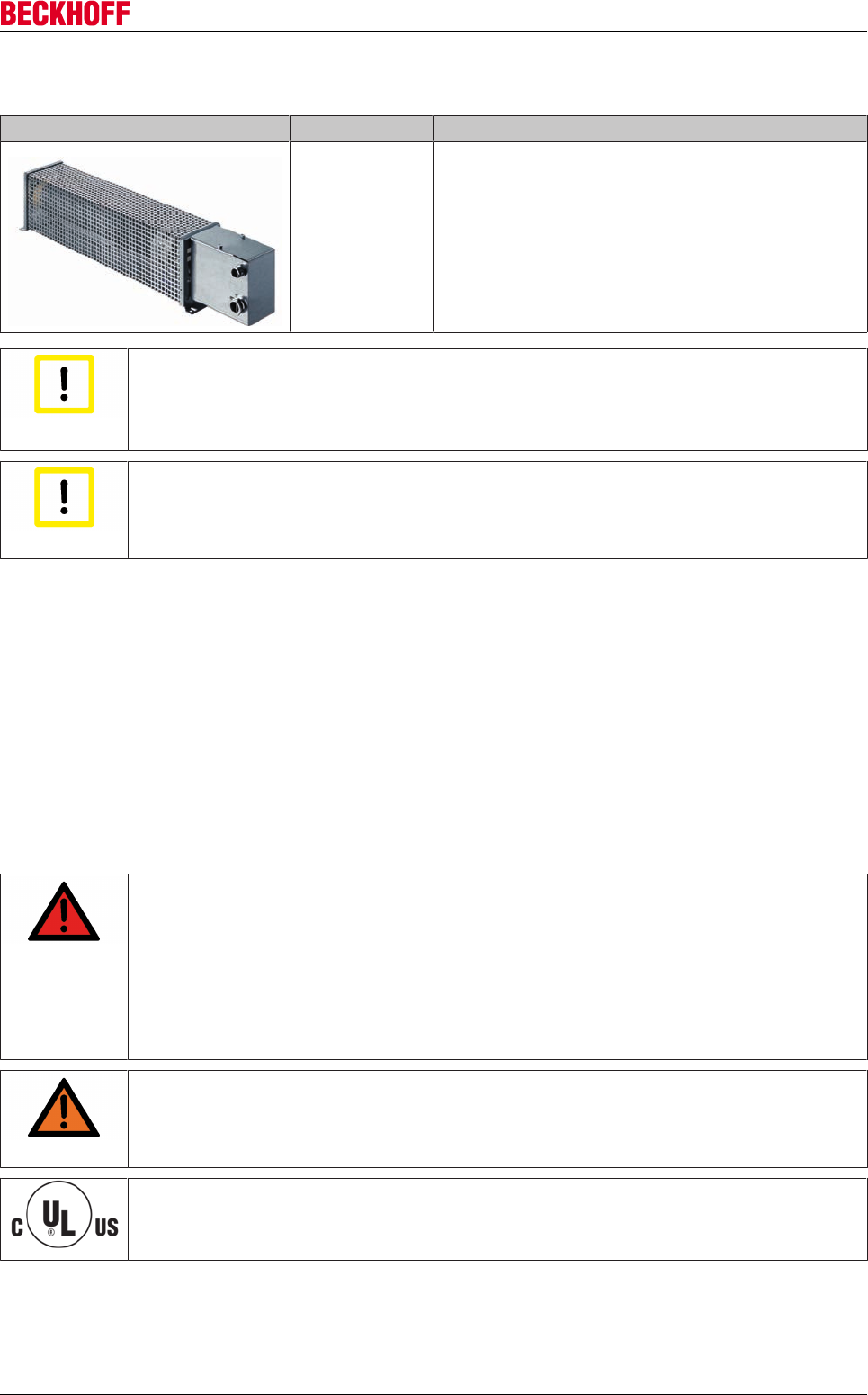
Accessories
Servo Drives AX5000 235
Version: 2.4
12.5 External Brake Resistor AX2090-BW5x
Figure Art.-No. Description
AX2090-BW5x The external brake resistors of the AX2090-BW5x
series are able to convert the dynamic energy
generated during braking of a servomotor into heat.
The built-in temperature switch enables the system to
respond immediately to any overload of the brake
resistor through analysis in the AX5000 or the PLC.
All brake resistors of the AX2090-BW5x-xxxx series
are UL and CSA approved.
Attention
Caution - Destruction of the equipment
The brake resistor may only be connected to individual AX5000 devices or AX5021 brake
modules. It must never be used in a drive system without the AX5021 brake module, since
this may lead to its destruction through overload.
Attention
Caution - Destruction of the brake resistor and consequential damage
The built-in temperature switch must be monitored, so that the machine can be stopped in
a controlled manner and switched off in the event of an overloading of the brake resistor.
12.5.1 Appropriate use
The brake resistors from the AX2090-BW5x-xxxx series are exclusively designed for direct application with
an AX5000 series servo drive or the AX5021 brake module. They are designed for installation as
components in electrical installations and machines together with the servo drive or the brake module, and
this is their only purpose.
12.5.2 Safety rules
The responsible staff must ensure that the application or use of the products described satisfy all the
requirements for safety, including all the relevant laws, regulations and guidelines.
DANGER
Serious risk of injury through electric shock!
Due to the DC link capacitors dangerous voltage (> 890VDC) may persist at the DC link con-
tacts “ZK+ and ZK- (DC+ and DC-)“ and “RB+ and RB-“ after the servo drive has been dis-
connected from the mains supply. After disconnecting the servo drive wait at AX5101 -
AX5125 and AX520x; 5 minutes, at AX5140/AX5160/AX5172; 15 minutes, at AX5190/
AX5191; 30 minutes and at AX5192/AX5193; 45 minutes and measure the voltage at the
DC link contacts ZK+ and ZK- (DC+ and DC-). The device is safe once the voltage has
fallen below 50 V.
WARNING
Caution - Risk of injury through hot surfaces!
The temperature of the brake resistor housing surface may reach over 200 °C. Please en-
sure that the housing has cooled down below 40 °C before touching it.
UL-Listing!
It is essential to observe directives and standards if you wish to operate an AX5000 in an
economic area that requires a UL-Listing.
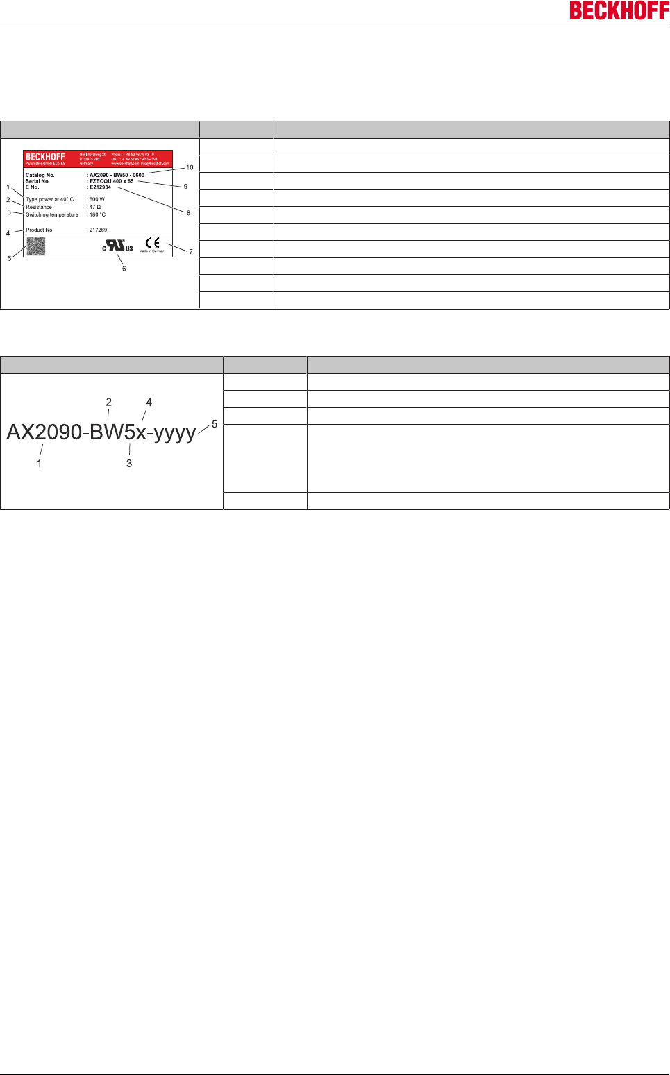
Accessories
Servo Drives AX5000236 Version: 2.4
12.5.3 Product identification
Name plate
Figure Pos.-No. Description
1 Type power at 40 °C
2 Resistance
3 Switching temperature
4 Product no
5 Barcode
6 UL-Recognized Component – certification
7 CE – certification
8 E no.
9 Serial no.
10 Catalog no.
Type key
Figure Pos.-No. Description
1 Drive Technology Acessories
2 BW = brake resistor
3 Servo drive AX5000
4 0 = AX5000 up to 12 A rated channel current
1 = AX5118 up to AX5140
2 = AX5160 up to AX5172
3 = AX5190 up to AX5191
4 = AX5192 up to AX5193
5 AX5000
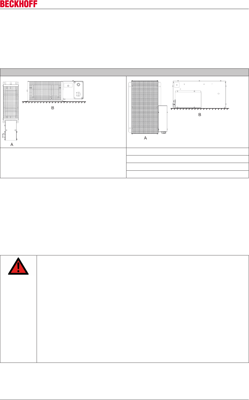
Accessories
Servo Drives AX5000 237
Version: 2.4
12.5.4 Mechanical installation
12.5.4.1 Mounting positions and distances
(A) = vertical installation is only permitted according to the diagram (terminal box facing downwards).
(B) = horizontal installation
Assignment of the device classes
AX2090-BW50-xxxx
AX2090-BW51-1000
AX2090-BW51-3000 and AX2090-BW51-6000
AX2090-BW52-3000 and AX2090-BW52-6000
AX2090-BW53-3000 and AX2090-BW53-6000
AX2090-BW54-3000 and AX2090-BW54-6000
For all mounting positions the following minimum distances must be adhered to:
200 mm to adjacent components, walls etc. and 300 mm to components, ceilings etc. above. If the device is
installed vertically (A), the minimum distance to components, floors etc. below is 200 mm in order to allow
unobstructed flow of air to the brake resistor.
12.5.5 Electrical installation
12.5.5.1 Important notes
DANGER
Serious risk of injury through electric shock!
Only staff qualified and trained in electrical engineering are allowed to wire up the brake re-
sistors.
• Check the assignment of the servo drive and the brake resistor. Compare the rated
voltage and the rated current of the devices.
• Always make sure that the brake resistors are de-energized during assembly and
wiring, i.e. no voltage may be switched on for any piece of equipment which is to be
connected. Ensure that the control cabinet remains turned off (barrier, warning signs
etc.). The individual voltages will only be turned on again during commissioning.
• Due to the DC link capacitors, the DC link contacts "ZK+ and ZK- (DC+ and DC-)" and
"RB+ and RB-" may be subject to dangerous voltages exceeding 890VDC, even after the
servo drive was disconnected from the mains supply.
Wait 5 minutes for the AX5101 - AX5125 and AX520x; 15 minutes for the AX5140/
AX5160/AX5172; 30 minutes for the AX5190/AX5191; 45 minutes for the AX5192/
AX5193 after disconnecting, and measure the voltage at the DC links "ZK+ and ZK-
(DC+ and DC-)". The device is safe once the voltage has fallen below 50 V.
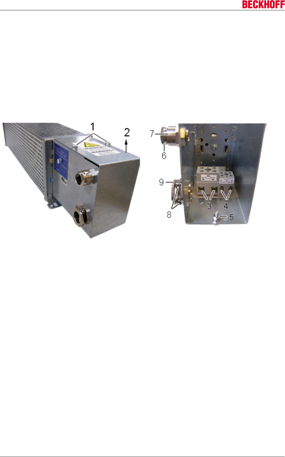
Accessories
Servo Drives AX5000238 Version: 2.4
12.5.5.2 Connection the brake resistor
Remove the two screws (1) and remove the cover (2) in direction of the arrow. Connect an adequately
dimensioned cable (see chapter "Cables") to the connections (3) of the resistor and the earthing stud (5) and
take it out of the terminal box through the strain-relief assembly (9). Ensure adequate strain relief with the
two screws (8). Connect the other side of the cable to the DC link contact connector "X2" of the AX5000. The
connector is supplied with the AX5000. Connect the earthing cable to the earthing conductor of the control
cabinet.
Connect an adequately dimensioned cable to the potential-free N/C contact (4) of the temperature switch
and take it out of the terminal box through the strain-relief assembly (7) (see chapter "Temperature switch").
Ensure adequate strain relief with the nut (6).
Install the cover (2) in reverse order.
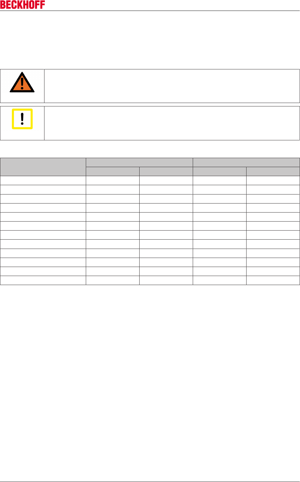
Accessories
Servo Drives AX5000 239
Version: 2.4
12.5.5.3 Cables
Beckhoff offers pre-assembled cables for safe, faster and flawless installation of the motors. Beckhoff cables
have been tested with regard to the materials, shielding and connectors used. They ensure proper
functioning and compliance with statutory regulations such as EMC, UL etc. The use of other cables may
lead to unexpected interference and invalidate the warranty.
WARNING
Caution - Fire hazard!
The brake resistors can reach temperatures of almost 200 °C. Therefore, ensure adequate
thermostability of the cables! Cables with inadequate thermostability can cause a cable fire!
Attention
EMC safety
Use only shielded cables.
Type Brake resistor Temperature switch
[mm2] [AWG] [mm2] [AWG]
AX2090-BW50-0300 1,5 16 0.75 18
AX2090-BW50-0600 1,5 16 0.75 18
AX2090-BW50-1600 1,5 16 0.75 18
AX2090-BW51-1000 2,5 12 0.75 18
AX2090-BW51-3000 2,5 12 0.75 18
AX2090-BW51-6000 2,5 12 0.75 18
AX2090-BW52-3000 4,0 12 0.75 18
AX2090-BW52-6000 4,0 12 0.75 18
AX2090-BW53-3000 6,0 12 0.75 18
AX2090-BW53-6000 6,0 12 0.75 18
AX2090-BW54-3000 6,0 12 0.75 18
AX2090-BW54-6000 6,0 12 0.75 18
We recommend wire end sleeves.
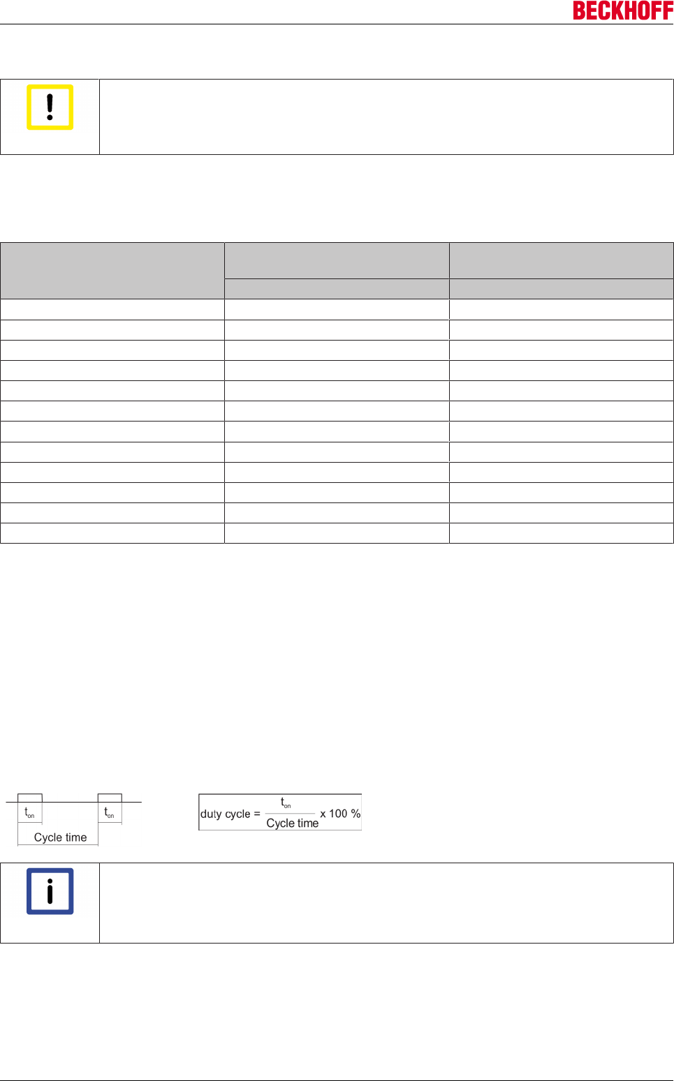
Accessories
Servo Drives AX5000240 Version: 2.4
12.5.5.4 Temperature switch
Attention
Destruction of the brake resistor!
The temperature switch is exclusively used for temperature monitoring. The brake resistor
is not switched off.
The temperature switch has a potential-free N/C contact, which enables immediate response to any overload
of the brake resistor through analysis in the AX5000 or the PLC. Connect the cable directly to a free input of
plug "X06". Then parameterize it such that the AX5000 stops the motor(s) with an emergency ramp or the
PLC reads and processes this input.
Type Switching temperature Switching current
24 VDC or 230 VAC
[°C] [A]
AX2090-BW50-0300 180 2
AX2090-BW50-0600 180 2
AX2090-BW50-1600 180 2
AX2090-BW51-1000 180 2
AX2090-BW51-3000 85 2
AX2090-BW51-6000 85 2
AX2090-BW52-3000 85 2
AX2090-BW52-6000 85 2
AX2090-BW53-3000 85 2
AX2090-BW53-6000 85 2
AX2090-BW54-3000 85 2
AX2090-BW54-6000 85 2
12.5.5.5 Short-term capacity
Brake resistors are usually not operated continuously, but only exposed to short-time duty. In the following
section the permitted short-term capacity is calculated based on the continuous power, overload factor and
duty cycle.
12.5.5.5.1 Duty cycle
The duty cycle is a relative value that depends on the switch-on time (ton) and the cycle time. Cycle times up
to 120 sec. are used directly in the calculation. Should the cycle time exceed 120 sec., the maximum
relevant cycle time of 120 sec. is used in the calculation.
Sample 1
Ton = 60 s
Cycle time = 280 s
Duty cycle = 50%
Sample 2
Ton = 40 s
Cycle time = 100 s
Duty cycle = 40 %
Note
Further information of external brake resistors:
For further information on the configuration and diagnostics of external brake resistors,
please refer to the function description of the servo drive AX5000: “Diagnostic of external
brake resistors”.
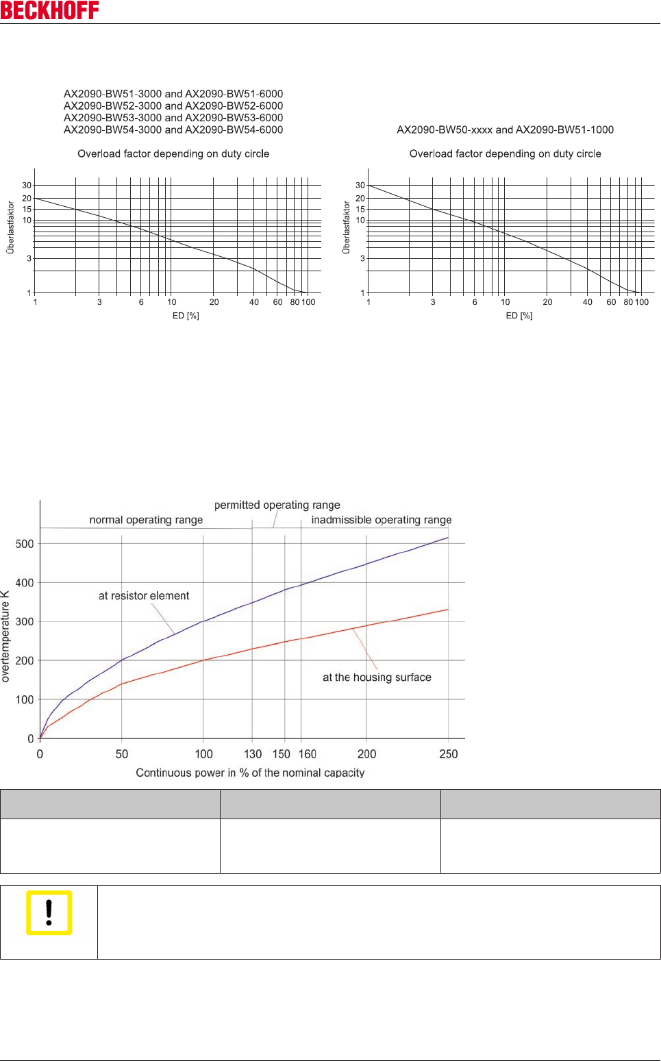
Accessories
Servo Drives AX5000 241
Version: 2.4
12.5.5.5.2 Overload factor
Calculation formula
Short-term capacity = continuous power x overload factor
12.5.5.6 Overtemperature and continuous power at 100% duty cycle
If your application requires a higher continuous power than the specified nominal capacity, you can accept
this state if a higher brake resistor temperature is permitted. The following diagram shows the
overtemperature v. the continuous power.
Normal operating range,
max. 130%
Permitted operating range,
max. 160%
Inadmissible operating range,
more than 160%
This operating range is recommended for
maximum service life and error-free opera-
tion.
This operating range is still permitted, al-
though it results in shorter service life with
higher failure probability
In this operating range there is a risk of de-
struction of the brake resistor through over-
heating. Due to the high temperatures the
adjacent components are also at risk.
Attention
Destruction of the brake resistor and adjacent components
Always ensure adequate ventilation of the brake resistor, since the temperatures of the
housing surface may exceed 200 °C.
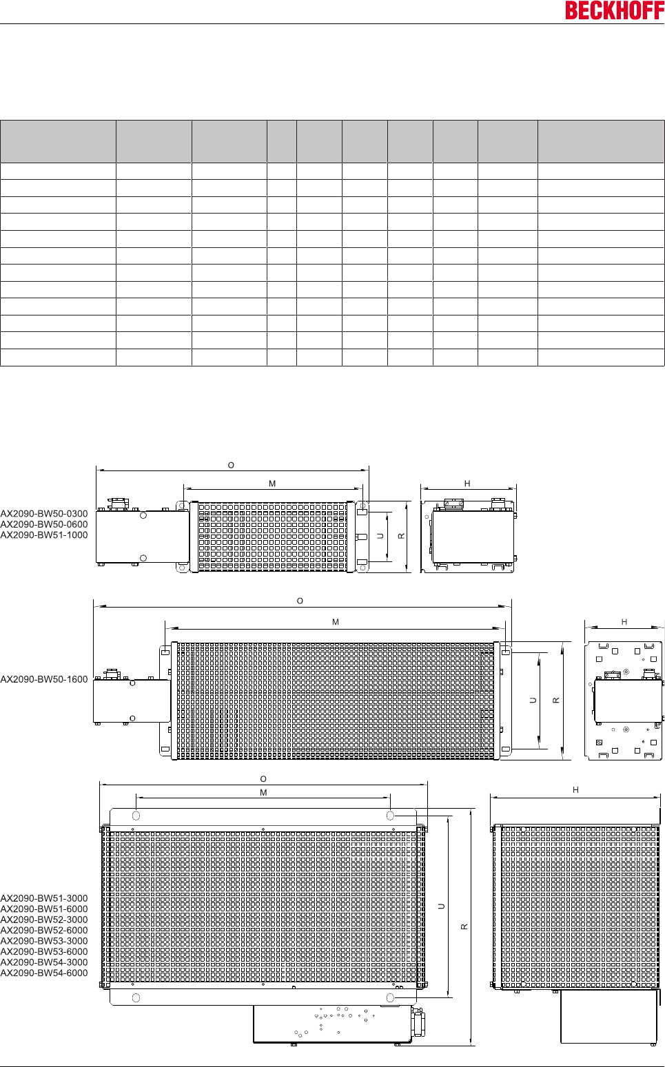
Accessories
Servo Drives AX5000242 Version: 2.4
12.5.6 Technical data
Dimensions
Type1) Type power
[W] * at 40 °C
Resistance
[Ω]
O
[mm
]
R
[mm]
H
[mm]
M
[mm]
U
[mm]
Weight
[kg]
AX5000
AX2090-BW50-0300 300 47 349 92 120 230 64 2 AX5x01-AX5112
AX2090-BW50-0600 600 47 549 92 120 430 64 3 AX5x01-AX5112
AX2090-BW50-1600 1600 47 649 185 120 530 150 5,8 AX5x01-AX5112
AX2090-BW51-1000 1000 23 749 92 120 630 64 4 AX5118-AX5140
AX2090-BW51-3000 3000 23,4 490 355 255 380 270 8 AX5118-AX5140
AX2090-BW51-6000 6000 23,2 490 455 255 380 370 12 AX5118-AX5140
AX2090-BW52-2000 3000 13,2 490 355 255 380 270 8 AX5160-AX5172
AX2090-BW52-6000 6000 13,0 490 455 255 380 370 12 AX5160-AX5172
AX2090-BW53-3000 3000 10,2 490 355 255 380 270 8 AX5190-AX5191
AX2090-BW53-6000 6000 10 490 455 255 380 370 12 AX5190-AX5191
AX2090-BW54-3000 3000 6,6 490 355 255 380 270 8 AX5192-AX5193
AX2090-BW54-6000 6000 6,5 490 455 255 380 370 12 AX5192-AX5193
*) 4% decrease in performance per 10K temperature difference
1) All external brake resistor have the protection class IP20
Technical drawings
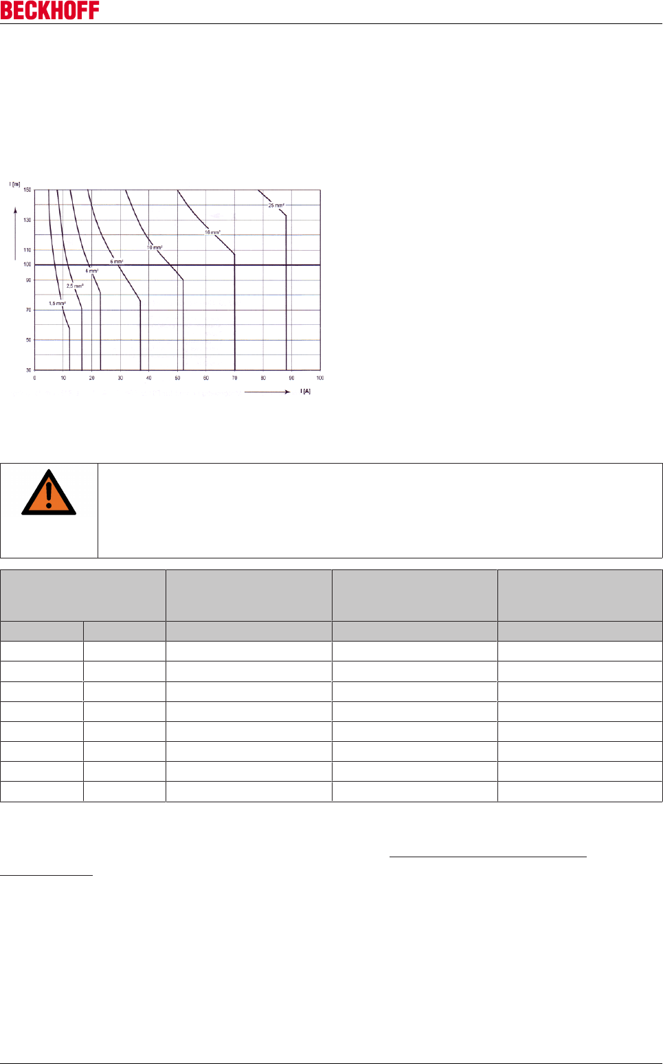
Accessories
Servo Drives AX5000 243
Version: 2.4
12.6 Cables
12.6.1 General specification
Wire cross-section depending on the cable length (according to EN60402)
Beckhoff offers pre-assembled motor and feedback
cables for faster and flawless installation. Design,
dimensioning and installation have significant
influence on the function of a servo system. Beckhoff
servo cables have been tested with regard to the
material used, shielding and connection, in order to
guarantee proper function and compliance with
statutory requirements such as EMC. The use of
other may invalidate the warranty.
12.6.1.1 Line load for different types of installation
WARNING
Fire hazard!
If several servo drives are operated at the same time the resulting total current of the con-
figuration must be taken into account for dimensioning of the cables. The information pro-
vides in this section should be regarded as guidance. It is not intended as a substitute for
professional design based on the specific application.
Cable cross-section Three-core non-metallic
sheathed cable or con-
duit
Three-core non-metallic
sheathed cable, stacked
on wall
Three-core non-metallic
sheathed cable, side by
side, horizontal
[mm²] [AWG] [A] [A] [A]
1.5 16 12.2 15.2 16.1
2.5 12 16.5 21.0 22
4 10 23 28.0 30
6 10 29 36.0 37
10 8 40 50.0 52
16 53 66.0 70
25 67 84.0 88
35 83 104.0 114
Line load according to EN60204-1, Table 5, at an ambient temperature of 40°C
The cable descriptions can be found on the Beckhoff website at http://www.beckhoff.de/motion/
documentation.
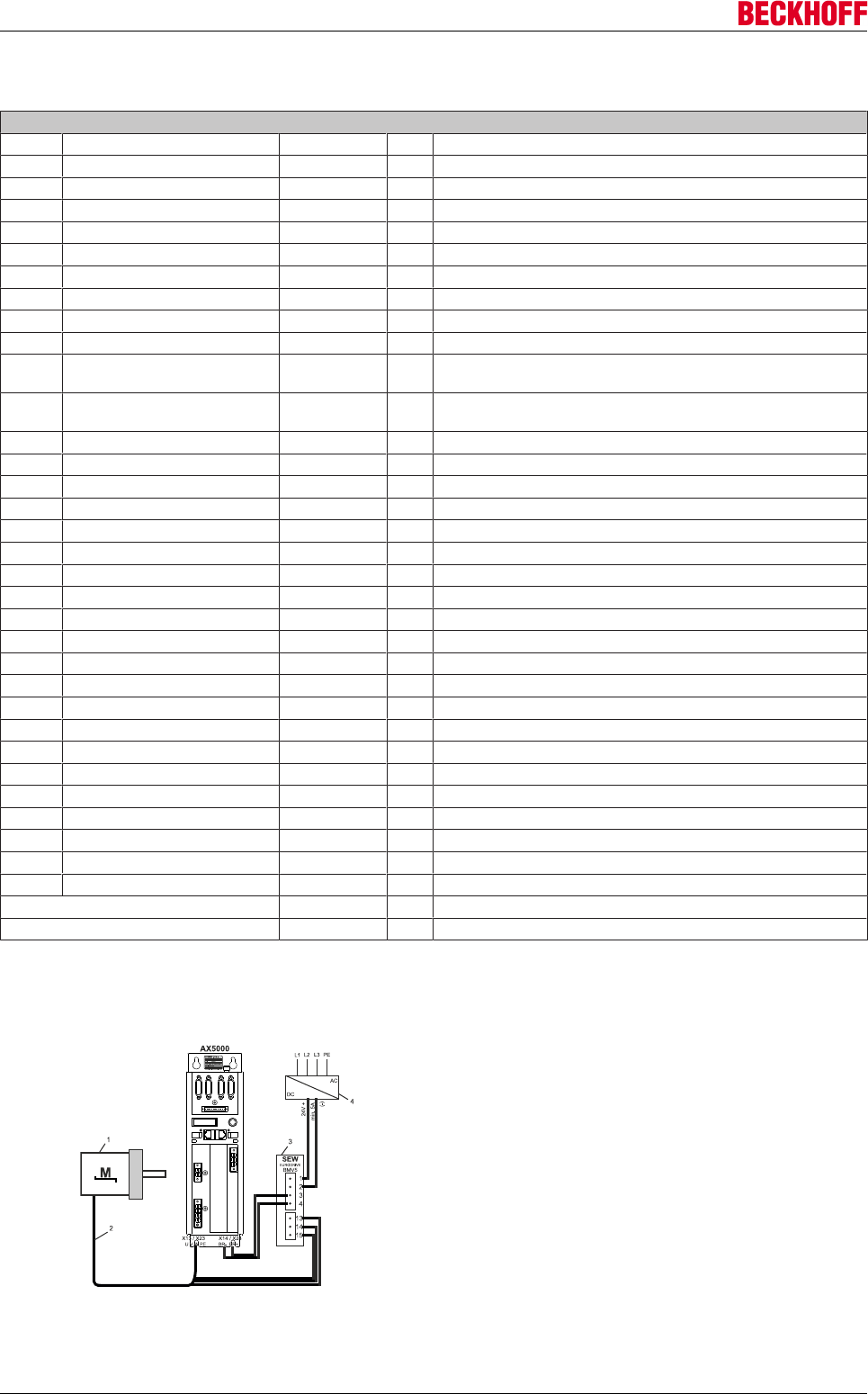
Accessories
Servo Drives AX5000244 Version: 2.4
12.6.2 Order key for motor and feedback cables
Z K 4 t u v - w w x y - z z z z
t Servo drive series 5 = AX5000
u Function 0 = Motor cable
1 = Encoder cable EnDat, Hiperface, BiSS
2 = Encoder cable Sin/Cos with zero pulse
3 = Resolver cable
4 = Temperature cable AL2000
5 = Hall cable for AL2000
v Function 0 = Motor - drive
1 = Extension cable
2 = Motor – choke (only AM3000 cable)
4 = Motor - other side
The free end is fitted with wire end sleeves
5 = Drive - other side
The free end is fitted with wire end sleeves
9 = Raw material
ww Motor series 0 0 = AL2000/AM2000/AM3000/AM3500
01 to 19 = Beckhoff
80 to 89 = Beckhoff
20 to 29 = Alpha EnDat / Alpha resolver
30 to 39 = Lenze
40 to 49 = SEW
50 to 59 = Siemens
60 to 79 = Further
x Quality 90 to 99 = Further
0 = fixed installation / no motion
1 = dynamic / drag chain
2 = high dynamic / high-speed chain
6 = high torsion cable
y Cross-section [mm²] 0 = Feedback
1 to 8 = 0.75=1 / 1.0=2 / 1.5=3 / 2.5=4 / 4.0=5 / 6.0=6 / 10=7 / 16=8
9 = special
90 = 25
91 = 35
92 = 50
z z z z Length in dm
applies only if Y ≠ 9 0001 to 9999 = 1 to 1000 m
applies only if Y > 9 _001 to _999 = 1 to 100 m
12.6.3 SEW motors from the “DFS / CFM” range with stopping brake
The stopping brake of the SEW motors has to be connected via a
brake rectifier, to guarantee the “quick activation of the brake”. A 3
wire connection cable is required for this. The following schematic
diagram shows the correct connections of the motors to the
AX5000.
• SEW servo motor of the DFS/ CFM range (1)
• Motor brake cable ZK4500-4xxx (2)
• SEW- BMV5 brake rectifier (3)
• Power supply unit with 5A minimum output current (4)
Accessories
Servo Drives AX5000 245
Version: 2.4
12.6.4 Special motor connections
12.6.4.1 Linear motors of the AL2xxx series
12.6.4.1.1 Installation
WARNING
Caution – Risk of injury through electric shock!
Remove the motor and feedback lines from the connector box to the servo drive when you
open the connector-box.
Note
Attaching the connector box!
The linear motor cables are not for trailing cables, hence the connector box has to be fixed
on the moving part of the linear motor.
Unscrew the cover and fix the connector box with 2 M4 screws on the carriage of the linear motor.
Motor cable:
Strip the wires of the motor cable and fit wire end sleeves. Twist the screen of the motor cable and solder on
a cable with a minimum diameter of 1.5 mm2. Fit wire end sleeves or a cable lug to the free end. Place the
nut of socket “A” over the motor cable and feed the wires through the socket “A” in the box and screw the nut
onto socket “A”. Fit the shielded and PE cables with a “PE” connection and the power wires on connection
“X1”.
Encoder cable:
Strip the wires of the encoder cable and fit wire end sleeves. Twist the screen of the encoder cable and
solder on a cable with a minimum diameter of 0.75 mm2. Fit wire end sleeves or a cable lug to the free end.
Place the nut of socket “B” over the encoder cable and feed the wires through the socket “B” in the box and
screw the nut onto socket “B”. Fit a “PE” connection to the shielded cable. Wire the signal wires to the “X2”
connection as per the table.
Connection pin Signal description MES
AL2200
LIKA
SMS-V1
SIKO
LE100
NJ*
LIA 1 Vss
X1-PE PE / GND shield shield shield wh / gn
X2-1 COS - red orange green red
X2-2 GND white black black white
X2-3 SIN - yellow blue orange yellow
X2-4 + 5V DC brown red brown brown
X2-5 DATA + / Z + --- white blue grey
X2-6 n.c. --- --- --- ---
X2-7 PTC --- --- --- ---
X2-8 Clock+ --- --- --- ---
X2-9 COS + blue green yellow blue
X2-10 GND sense grey --- --- ---
X2-11 SIN + green yellow red green
X2-12 + 5V sense pink --- --- ---
X2-13 DATA - / Z - --- --- violet pink
X2-14 PTC --- --- --- ---
X2-15 Clock- --- --- --- ---
Thermal protection cable:
Strip both wires of the thermal protection contact cable and fit wire end sleeves. Twist the screen of the
thermal protection contact cable and solder on a cable with a minimum diameter of 0.75 mm2. Fit wire end
sleeves or a cable lug to the free end. Place the nut of socket “C” over the thermal protection contact cable
and feed the wires through the socket “C” in the box and screw the nut onto socket “C”. Fit a “PE” connection
to the shielded cable. Fit both thermal protection contact wires to contacts “7” and “14” of connection “X2”.
Retighten the connector box cover.
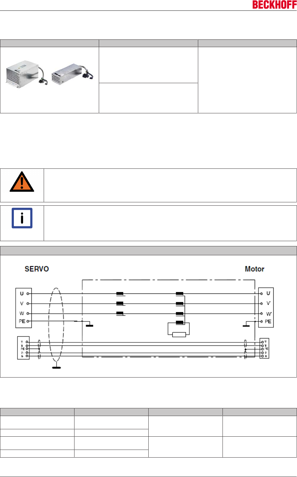
Accessories
Servo Drives AX5000246 Version: 2.4
12.7 Motor chokes AX2090-MD50
Figure Art.-No. Description
AX2090-MD50-0012
motor choke for AX5000 (1.5…12 A),
necessary for motor cable ≥ 25 m, up to 12
A rated current, necessary for motor cable ≥
25 m, max. 100 m, with integrated
connection cable (150 mm)
A motor choke must be installed between
the AX5000 and the motor from a certain
motor cable length onwards. The motor
choke reduces the commutation current
flowing via the screen back into the AX5000
to a permissible value and can also provide
a solution to EMC problems.
AX2090-MD50-0025
motor choke for AX5000 (18…25 A), up to
25 A rated current, necessary for motor
cable ≥ 25 m, max. 50 m, with integrated
connection cable (150 mm)
12.7.1 Electrical connection
The motor chokes are connected based on the "plug & play" principle. Pull the two plug connectors from the
existing motor cable of the AX5000 and plug them into the sockets of the motor choke. The two plugs of the
integrated motor choke cable are then plugged into the socket of the AX5000.
WARNING
Caution - Risk of injury through electric shock!
De-energize all electrical components (servo drive, control cabinet etc.) before commenc-
ing the installation or deinstallation of the motor choke.
Note
Connection cables
Use exclusively Beckhoff motor cables and firmly tighten the connecting plugs. Max. tight-
ening torque - M4 thread = 1.5 Nm ±0.1 Max. tightening torque - M3 thread (motor connec-
tor) = 0.6 Nm ±0.1.
Connection example
12.7.2 Technical data
Rated motor current Motor cable length Servo Drives Motor choke
max. 400 V >20 m to 100 m AX5101, AX5103, AX5106,
AX5112,
AX5201, AX5203, AX5206
AX2090-MD50-0012
max. 480 V >20 m to 100 m
max. 400 V >20 m to 50 m AX5118 and AX5125 AX2090-MD50-0025
max. 480 V >20 m to 50 m

Accessories
Servo Drives AX5000 247
Version: 2.4
Data AX2090-MD50-0012 AX2090-MD50-0025
Rated voltage 480 V AC 480 V AC
Rated frequency 0 - 60 Hz 0 – 60 Hz
Test voltage cable/cable for 2 s 1770 V DC 1770 V DC
Test voltage cables/housing for 2 s 2700 V DC 2700 V DC
Rated temperature 50 °C 50 °C
Inductance 0.2 mH 0.12 mH
Continuous load operation (S1) 12 A 25 A
Climate category (IEC 60068-1) 25/100/21 25/100/21
Approval UL 1283 UL 1283
Resistance [type] 25 mΩ 15 mΩ
Power loss 5 - 25 W1)3) 10 -35 W2)4)
Weight 2.9 kg 8.5 kg
1)rated current 1 - 12 A
2)rated current 18 – 25 A
3)measured at max. cable length of 100 m
4)measured at max. cable length of 50 m
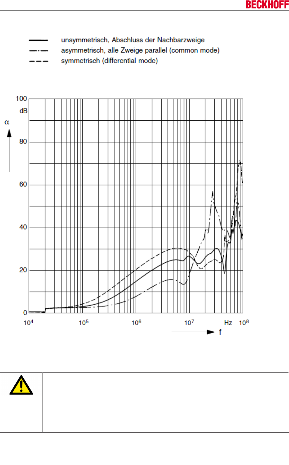
Accessories
Servo Drives AX5000248 Version: 2.4
Insertion attenuation (reference value Z = 50 Ω)
12.7.3 Installation of the motor choke AX2090-MD50-0012
CAUTION
Destruction of the motor choke!
• Always install the motor choke vertically on an earthed metallic mounting plate. If no
metallic mounting plate is available, you must earth the motor choke; an earthing bolt is
provided on the motor choke for this purpose.
• Ensure adequate ventilation of the motor choke. The permissible ambient conditions
are specified in the chapter "Technical data".
• It is essential to maintain the necessary distances to the AX5000 (see sketches below).
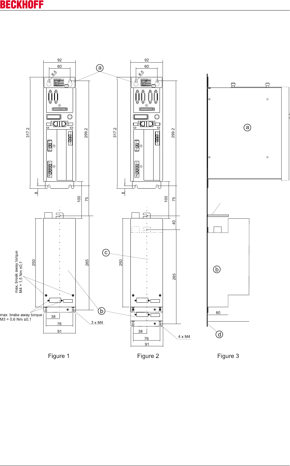
Accessories
Servo Drives AX5000 249
Version: 2.4
The motor chokes for the AX5000 (a) with a max. rated channel current of 12 A are bolted to the mounting
plate (d) below the device.
‘Figure 1’ shows a motor choke (b) for one channel.
In the case of 2-channel devices, the motor chokes are bolted on top of one another; see ‘figures 2 and 3’.
The spacer (e) is supplied with the motor choke.
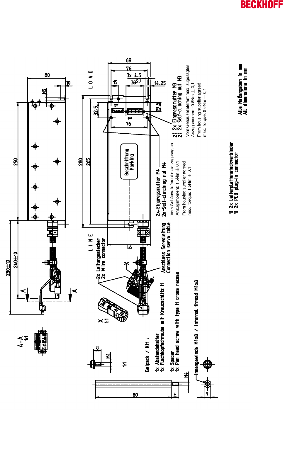
Accessories
Servo Drives AX5000250 Version: 2.4
12.7.4 Dimensions
12.7.4.1 AX2090-MD50-0012
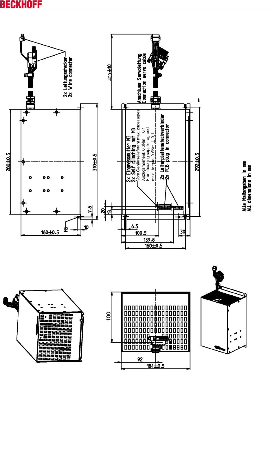
Accessories
Servo Drives AX5000 251
Version: 2.4
12.7.4.2 AX2090-MD50-0025
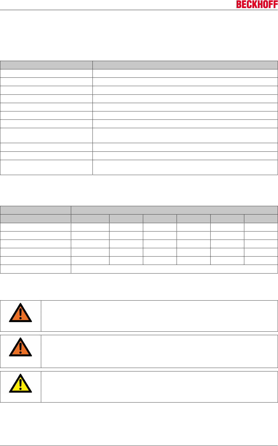
Accessories
Servo Drives AX5000252 Version: 2.4
12.8 Mains choke AX2090-ND50
12.8.1 Technical data
Environmental conditions Three-phase mains chokes AX2090-ND50
Rated voltage 3 x 460 V, -25% +10%, 50/60 Hz1)
Overload factor 2.0 x IN for 30 s
Ambient temperature -25 °C to +45 °C, with 1.3% (/°C) power derating to +60 °C
Mounting height 1000 m, with 6% (/1000 m) power derating to 4000 m
Relative humidity 15%…95%, condensation not permitted
Storage temperature -25 °C to +70 °C
Protection class IP00
Short-circuit voltage UK 4% at 400 V = 9.24 V
UK 2 % at 400 V = 4.6 V
Permissible level of contamination P2 according to EN 61558-1
Thermal configuration Ieff < IN
Material The AX2090-ND50 devices are UL-certified for the US and Canadian
markets
1) at 60 Hz mains frequency the power loss is approx. 10% higher!
Three-phase mains chokes
AX2090-ND50-
Data 0060 0072 0090 0110 0143 0170
Rated current [A] 60 72 90 110 143 170
Power loss [W] 70 80 120 140 160 170
Inductance [mH] 0.25 0.20 0.16 0.13 0.10 0.09
Weight [kg] 7 10 13 15 25 25
Connection [mm²] 16 16 35 35 70 70
Short-circuit voltage 4 % UK
12.8.2 Installing the mains chokes
WARNING
Caution - Risk of injury through electric shock!
De-energize all electrical components (servo drive, control cabinet etc.) before commenc-
ing the installation or deinstallation of the mains choke.
WARNING
Caution - risk of injury through high voltages!
Mains chokes contain components that can store electrical charge. Wait 10 minutes after
disconnecting the mains chokes and measure the voltage on conductors L1 to L3. You can
ensure safe working by letting the voltage drop below 50 V.
CAUTION
Beware of improper earthing!
Ensure proper earthing during installation of the mains chokes. The installation should take
place on a mounting plate (chromated / galvanized) suitable for earthing.
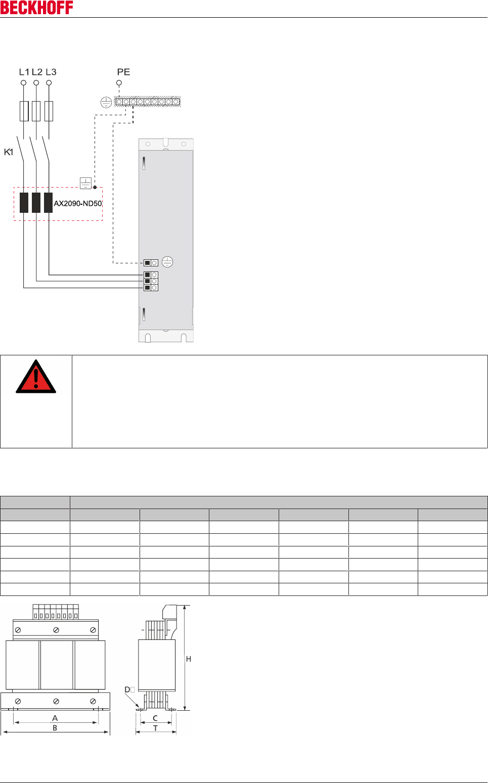
Accessories
Servo Drives AX5000 253
Version: 2.4
12.8.2.1 Circuit diagram and installing
Assembly sequence:
• Position the mains choke on the mounting
surface.
• Mark the positions of the thread holes on the
mounting surface.
• Centre and drill the thread holes. Then cut the
threads in the holes.
• Secure the mains choke on the mounting
surface with suitable screws.
Connection:
• Connect the protective conductor connection of
the mains choke with the PE rail.
• Connect the connecting cable of the mains
choke to the appropriate terminals of the servo
drive.
• Connect the mains choke to the supply
network.
DANGER
Serious risk of injury!
Due to the DC link capacitors dangerous voltage (> 890VDC) may persist at the DC link con-
tacts “ZK+ and ZK-“and “RB+ and RB-“ after the servo drive has been disconnected from
the mains supply. After disconnecting the servo drive wait at AX5160/AX5172; 15 minutes,
at AX5190/AX5191; 30 minutes and at AX5192/AX5193; 45 minutes and measure the volt-
age at the DC link contacts ZK+ and ZK-. The device is safe once the voltage has fallen be-
low 50 V.
12.8.2.2 Dimensional drawing
AX2090-ND50-
Dimension [mm] 0060 0072 0090 0110 0143 0170
B (Wigth) 190 190 230 230 240 240
H (Height) 200 240 300 300 330 330
T (Depth) 120 110 160 180 200 200
A 170 170 180 180 190 190
C 68 78 98 122 125 125
D 8 8 8 8 11 11
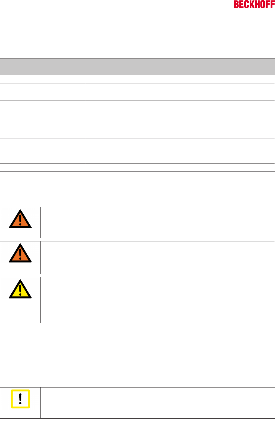
Accessories
Servo Drives AX5000254 Version: 2.4
12.9 Mains filter - AX2090-NF50
12.9.1 Technical data
AX2090-NF-50-
Data 0014 0032 0063 0100 0150 0180
Rated voltage [VAC] 480
Rated frequency [Hz] 50 / 60
Rated current [A] 14.6 32.8 63 100 150 180
Voltage cable/cable for 2 sec.
[VDC]
2236 -- -- -- --
Voltage cable/housing for 2 sec.
[VDC]
2720 -- -- -- --
Rated temperature [°C] 50 40
Climate category (IEC 60068-1) 25/100/21 -- -- -- --
Resistance [mΩ] 9 4 -- -- -- --
Leakage current [mA] 15 6.8 9.8
Weight [kg] 0.9 1.75 5.0 6.0 6.8 7.0
Approvals EN133200, UL1283, CSA C22.2 No.8 -- -- -- --
12.9.2 Installing the mains filter
WARNING
Caution - Risk of injury through electric shock!
De-energize all electrical components (servo drive, control cabinet etc.) before commenc-
ing the installation or deinstallation of the mains filter.
WARNING
Caution - Risk of injury through electric shock!
Mains filters contain components that can store electrical charge. Wait 5 minutes after dis-
connecting the filters and measure the voltage on conductors L1 to L3. The device is safe
once the voltage has fallen below 50 V.
CAUTION
Personal injuries!
When installing the mains filter, the protective earth cables must be connected first as a
matter of principle. They must be disconnected last when deinstalling. Depending on the
size of the leakage current, the special regulations for the implementation of the protective
earth connection must be observed. Minimum requirement for the protective conductor KU-
value 1) = 4.5 for leakage currents IL < 10 mA or KU = 6 for IL > 10 mA.
1) The KU-value is a variable for the classification of safety-related types of failure for protection against
dangerous shock current and excessive heating. A value of KU = 4.5 in relation to interruption is attained:
• with a permanently attached protective conductor ≥ 1.5 mm2
• for protective conductor connection ≥ 2.5 mm2 with plug connector for industrial systems (IEC
60309−2).
KU = 6 in relation to interruption is attained with permanently connected conductors ≥ 10 mm2, wherein the
type of connection and routing must comply with the standards applicable to PEN conductors.
Attention
Destruction of the mains filter
The mains filters must be protected by means of an appropriate overcurrent protection de-
vice against the impermissible exceeding of the rated current.
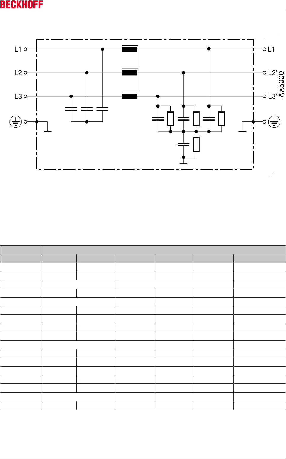
Accessories
Servo Drives AX5000 255
Version: 2.4
12.9.2.1 Circuit diagram
Connection cables
The length of the connecting cable from the mains filter to the AX5000 must not exceed 0.4 m. Use
exclusively shielded connecting cables.
12.9.2.2 Dimensions and dimensional drawings
AX2090-NF50-
Dimensions 0014 0032 0063 0100 0150 0180
B1 [mm] 38-0.3 35-0.3 40 45 60 180
B2 [mm] 46.4 58 62 75 90 200
B3 [mm] Ø 4.5 Ø 7 Ø 8.5
H1 [mm] 70 90 180 200 220 120
H2 [mm] 1.5 -- -- -- --
K [mm²] 4 10 0.6-16 16-50 35-95 Busbars
K1 [mm] -- -- -- -- -- 45
K2 [mm] -- -- -- -- -- 86
K3 [mm] -- -- -- -- -- 91
L1 [mm] 200 240 250 280 160
L2 [mm] 231 265 280 290 320 310
L3 [mm] 221-0.5 255-0.5 270 300 180
L4 [mm] -- -- 305 336 380 410
PE1 [mm] 60 70 -- -- -- 30
PE2 [mm] 9 8 -- -- -- --
PE [mm²] M5 M6 M8 M10
T [Nm] 0.5 – 0.6 1.2 – 1.5 -- -- -- --
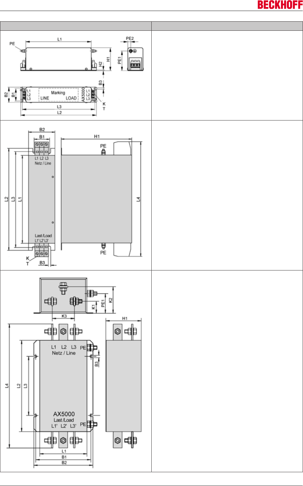
Accessories
Servo Drives AX5000256 Version: 2.4
Figure Mains filter
AX2090-NF50-0014
AX2090-NF50-0032
AX2090-NF50-0063
AX2090-NF50-0100
AX2090-NF50-0150
AX2090-NF50-0180
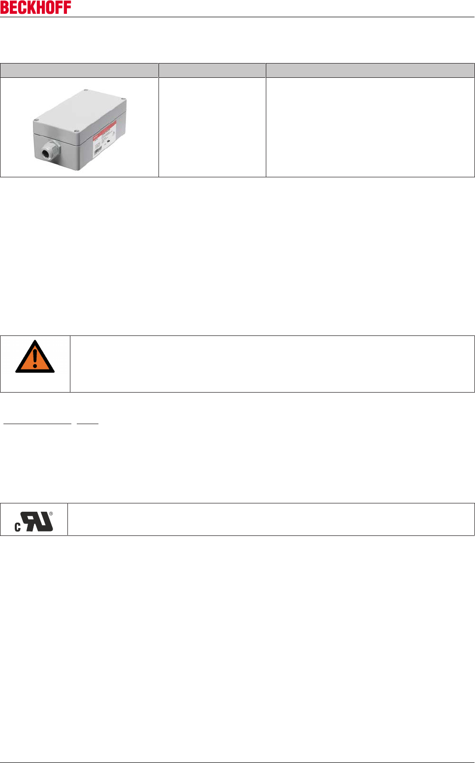
Accessories
Servo Drives AX5000 257
Version: 2.4
12.10 Transient voltage suppressor - AX2090-TS50
Figure Art.-No. Description
AX2090-TS50-3000 The Beckhoff transient box of the series
AX2090-TS50 enables voltage peaks, by
means of switching operations in electrical
circuits or by electrostatic discharges to be
recorded.
12.10.1 Guidelines and Standards
12.10.1.1 Appropriate use
The AX2090-TS50-3000 transient boxes are accessory components for the AX5000 servo drive series. They
are specifically designed for the Canadian market, to protect supply networks from overvoltages and to
absorb current peaks.
The AX2090-TS50-3000 transient boxes are always installed as control cabinet components and may only
be commissioned as integrated system components.
WARNING
Caution - Risk of injury!
Electronic equipment is not fail-safe. The machine manufacturer is responsible for ensuring
that the connected motors and the machine are brought into a safe state in the event of a
fault in the drive system.
The transient boxes may only be operated in closed control cabinets, under the conditions described in the
"Technical data [}258]" section.
12.10.1.2 CSA approval
The AX2090-TS50-3000 transient box series was approved by the American UL certification authority for the
Canadian market, in accordance with the standards and guidelines applicable in Canada.
Transient box with CSA approval:
AX52090-TS50-3000 – certified according to CAN / CSA C22.2 no. 274.
The cRU logo should be shown on the name plate. If you wish to operate an AX2090-TS50-3000 in Canada,
please check whether the name plate shows the cRU logo.
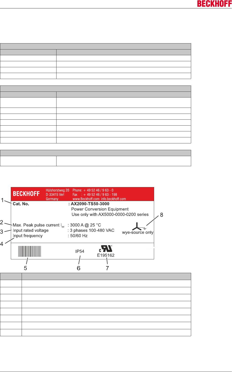
Accessories
Servo Drives AX5000258 Version: 2.4
12.10.2 Technical data
This section contains general technical data and ordering information for the Beckhoff AX2090-TS50-3000
transient box. See below for name plate information (technical approvals, certifications, mains supply, etc.).
AX2090-TS50-3000
Electrical data
Rated input voltage [VAC] 100 – 480
Max. pulse peak current [A] 3000 at 25 °C
Power derating 20% at 50 °C
Transient protection Fuse AX3-430C or similar according to E128662
AX2090-TS50-3000
Mechanical data
Material Housing: Cast aluminum
Cover: Cast aluminum with CR foam rubber perimeter seal
Surface Textured paint
Color RAL 7001
Ambient temperature [°C] -25 to +85
IP protection class IP 66 (closed state) according to IEC 60 529
NEMA protection class NEMA 4
Weight [kg] 1,56
AX2090-TS50-3000
Ordering information Transient protection for servo drives of the AX5101 – AX5125 and AX520x
series, required for CSA certification
12.10.2.1 Name plate
Item no. Name
1 Order number
2 Max. pulse peak current
3 Rated input voltage
4 Input frequency
5 Barcode
6 Protection class
7 cRU-compliant (E195162)
8 Standard mains supply with earthed center
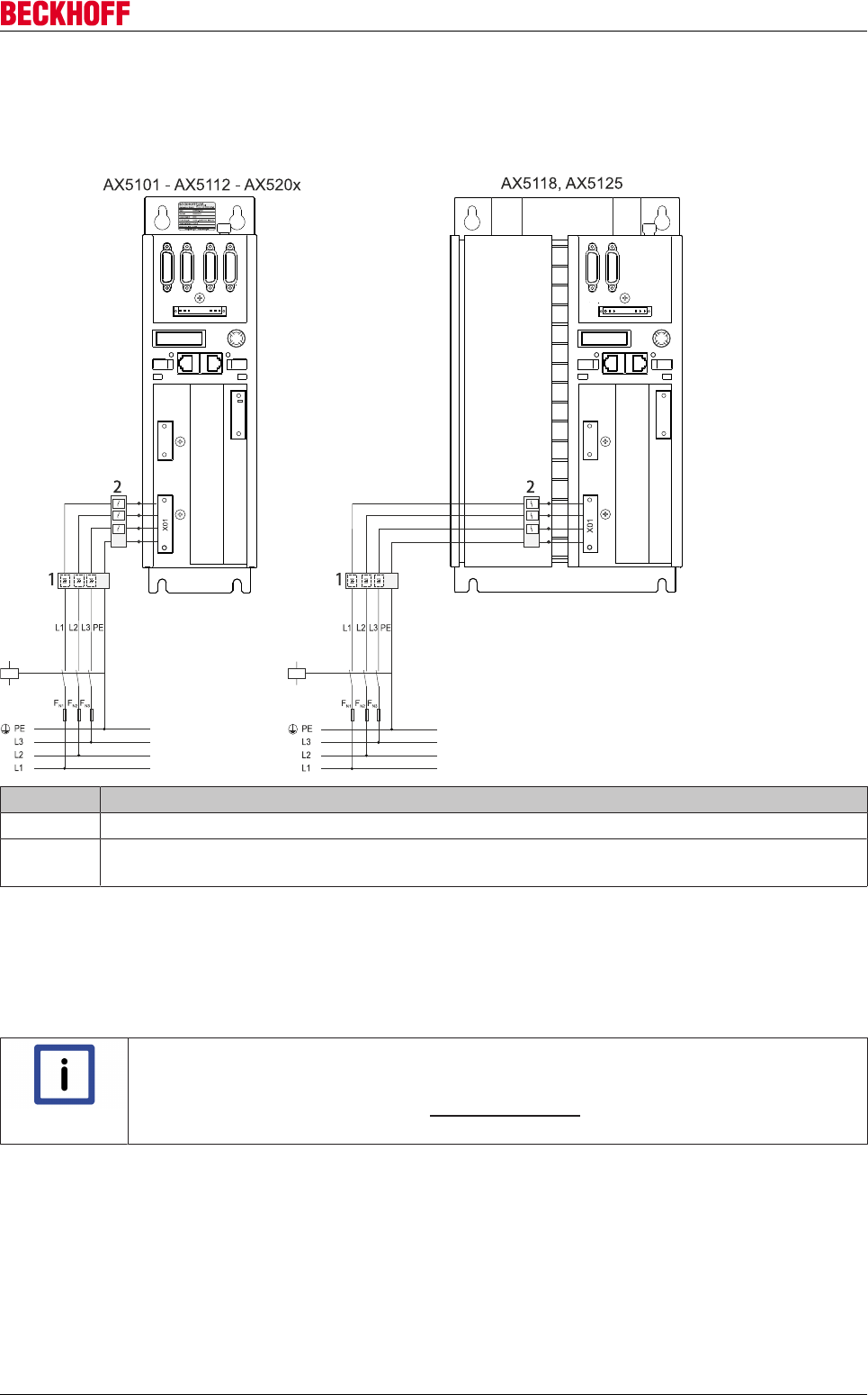
Accessories
Servo Drives AX5000 259
Version: 2.4
12.10.3 Installation of the transient box
12.10.3.1 Connection example
Item no. Name
1 Transient box AX2090-TS50-3000
2 Mains filter (optional) AX2090-NF50-0014 (AX5101 - AX5112 and AX520x)
Mains filter (optional) AX2090-NF50-0032 (AX5118 and AX5125)
Connection cables
When assembling the connecting cables note the following lengths:
• cable between the transient box and the mains filter (optional): min. 200 mm.
• cable between the mains filter and the AX5000 servo drive: max. 400 mm.
Note
EMC-compliant installation of the components and shield concept
For further information on EMC-compliant installation and the shield concept
please refer to the Beckhoff website (www.beckhoff.com) under:
Motion → Documentation → AX5000 – EMC leaflet.
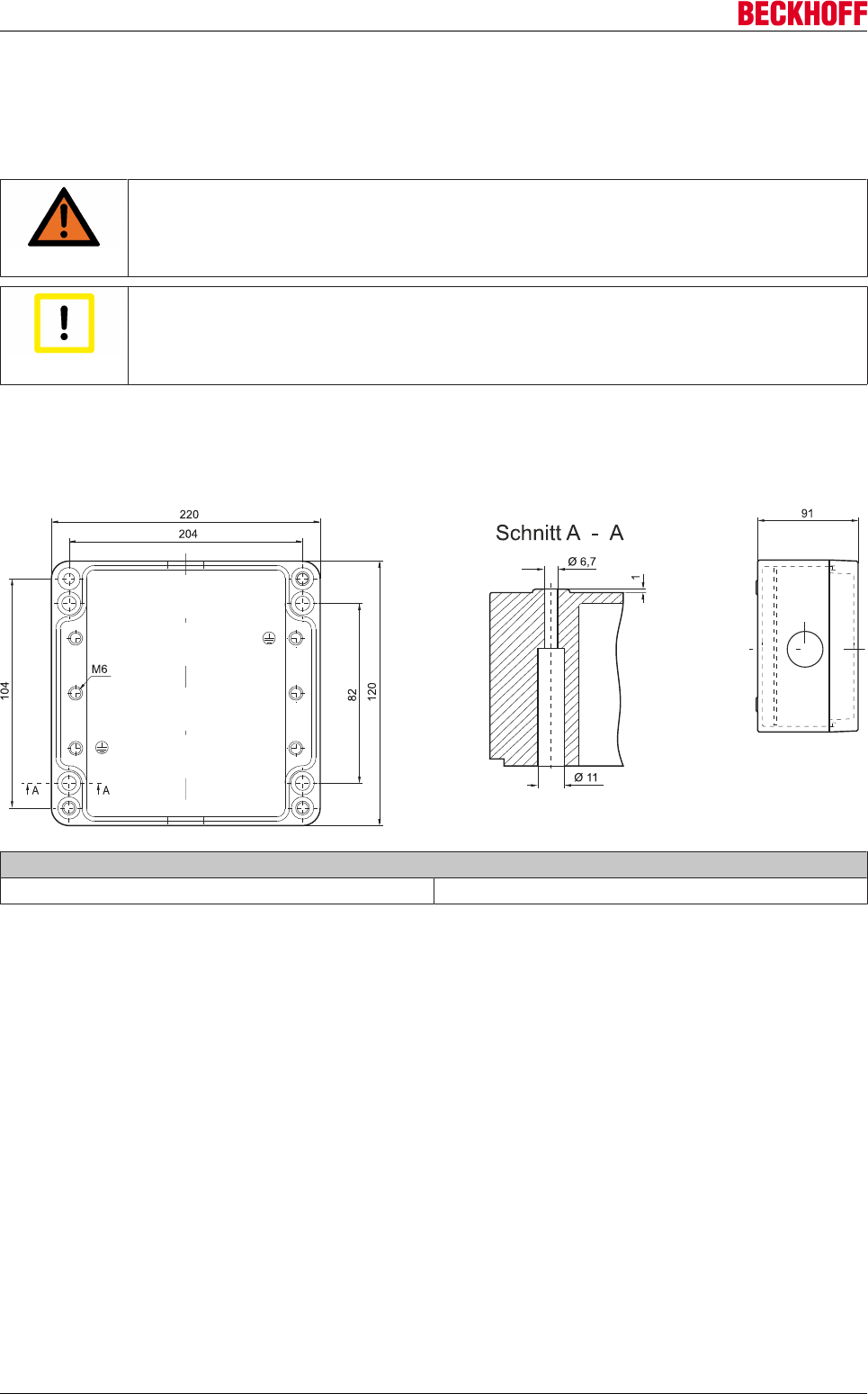
Accessories
Servo Drives AX5000260 Version: 2.4
12.10.3.2 Installation in the control cabinet
Beckhoff Automation GmbH & Co. KG recommends M6 screws with through-hole thread of strength grade
8.8 for installation of the transient box in the control cabinet. The screws should be tightened with a
maximum tightening torque of 7.3 Nm.
WARNING
Caution - Risk of injury through electric shock!
The mounting plate must be earthed according to the statutory regulations.
Attention
Earthing!
Improper earthing of the AX2090-TS50-3000 transient box can result in EMC problems.
12.10.3.3 Dimensions
AX2090-TS50-3000
Tightening torques for the fastening screws (cover)
M6 x 40 (4 screws) 2 +1 Nm
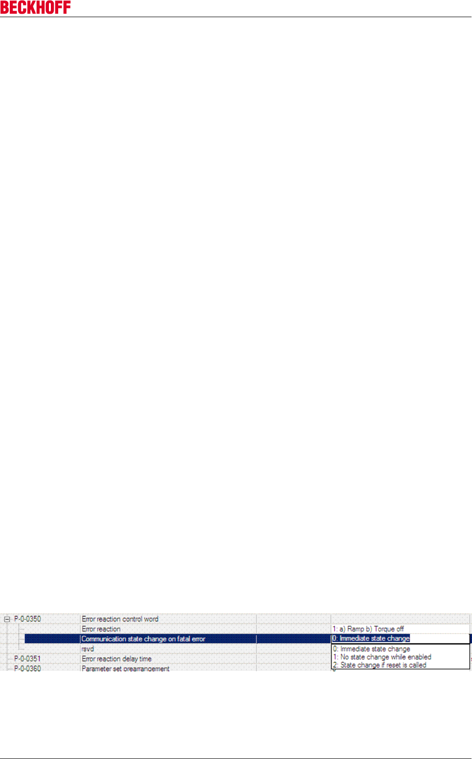
Appendix
Servo Drives AX5000 261
Version: 2.4
13 Appendix
13.1 Error management
13.1.1 General
Fatal errors are error types requiring reinitialization of the connected AX5000 feedback systems. For this the
communication status of the EtherCAT Slave State Machine must be changed from Operational (Op) to
Safe-Operational (Safe-Op), which takes place automatically on the occurrence of a fatal error in the case of
standard parameterization. In such a case the drive is in ErrSafe-Op, since an error is additionally signaled.
Since two-channel devices possess only one communication unit and no axis operation is possible in the
SafeOp state, both channels are stopped by default. In this particular case, the change from Op to ErrSafe-
Op results in the working counter of the SyncUnit becoming invalid, since the AX5000 can no longer supply
valid actual values, resulting in all servo drives in this SyncUnit being disabled.
13.1.2 Requirement
The measures described in this section assume the following software versions.
• TwinCAT v2.10 b1329 or later versions
• Firmware v2.x or later versions
13.1.3 Parameterization
A fatal error completely stops a two-channel device by default, i.e. the error-free channel and the associated
SyncUnit are also stopped. If such a behavior is not permitted in the application, the default behavior can be
changed with the following parameterization of IDN P0-0350.
P-0-0350: Change of communication state in the event of fatal errors
0: Immediate state change (default)
If the servo drive is in "Op" state when the fatal error occurs, it immediately changes from "Op" to "ErrSafe-
Op" and sets the error bit in the EtherCAT state.
1: No change in communication state while the other channel is enabled
In this case the AX5000 initiates the state change from Op to ErrSafe-Op in the event of a fatal error on one
channel only once the error-free channel has been deactivated. The error-free channel can therefore
continue to operate until it is deactivated.
2: Change of status when the reset command is called (S-0-0099)
In the case of an active fatal error, the AX5000 only changes to "ErrSafeOp" if the Reset command is
executed in the drive; hence, the change of state can be initiated at the best possible time from the
application by means of the Reset command.
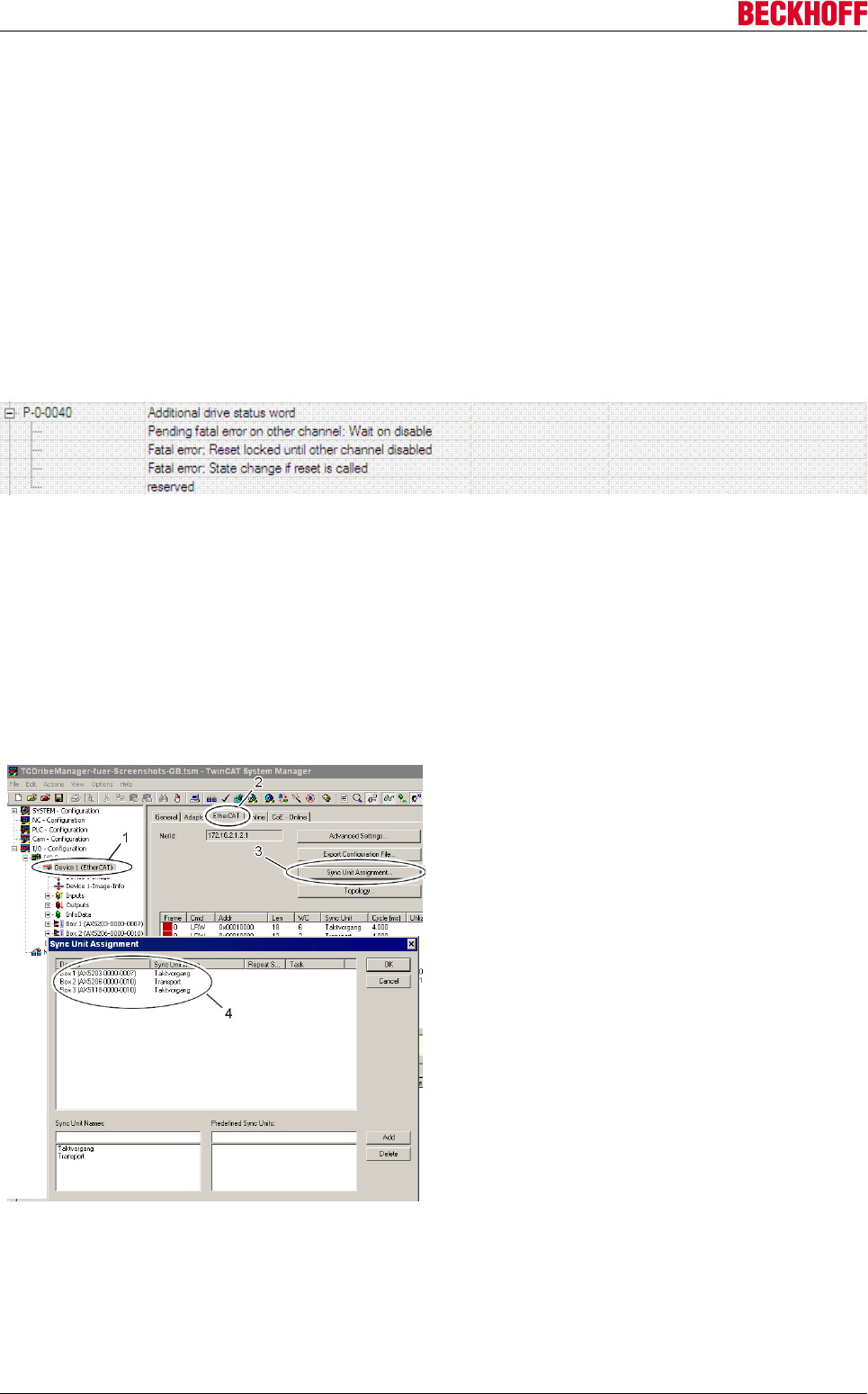
Appendix
Servo Drives AX5000262 Version: 2.4
PLC
The IDN P-0-0040 is used in order to be able to diagnose in the PLC whether a fatal error situation has
occurred that will lead to a change of status when next deactivating a channel or when calling the Reset
command. This IDN should be read acyclically in the PLC with block "FB_SoERead". Cyclic evaluation is not
meaningful, since the AX5000 no longer supplies valid inputs in ErrSafe-Op state after a fatal error, and
therefore no valid information is transferred cyclically.
Bit 0: this bit indicates whether the other channel has an error that will lead to a change of communication
from ‘Op’ to ‘ErrSafe-Op’ on deactivation of this channel.
Bit 1: this bit indicates whether this channel has a fatal error that will lead to a change of communication from
‘Op’ to ‘ErrSafe-Op’ on deactivation of the other channel. An error reset is not possible as long as this bit is
set.
Bit 2: this bit indicates whether this channel has a fatal error that will lead to a change of communication from
‘Op’ to ‘ErrSafe-Op’ on executing the Reset command.
13.1.4 SyncUnit diagnostics
The individual servo drives should be consolidated in meaningful groups, depending on the application. Each
of these groups is allocated to a SyncUnit. Since each group has its own working counter, the individual
groups can continue to operate independently in the event of fatal errors. For particularly critical applications,
each AX5000 can be allocated a separate Sync Unit. However, this step should only be implemented in
cases where it is actually required, because each further Sync Unit results in additional data traffic on the
EtherCAT strand.
Allocation of servo drives to a Sync Unit
Start the TwinCAT System Manager and left-click on
the associated EtherCAT strand (1). Select the
"EtherCAT" tab (2) and left-click on "Sync Unit
Assignment" (3). The "Sync Unit Assignment"
submenu appears. Section (4) shows the servo
drives and their allocation to the Sync Units. Servo
drives AX5203 and AX5118 belong to Sync Unit
"Cycle Process", 5206 belongs to Sync Unit
"Transport".
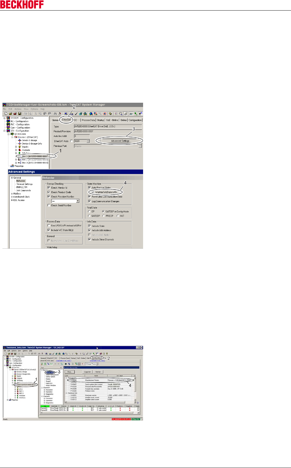
Appendix
Servo Drives AX5000 263
Version: 2.4
13.1.5 Reinitialization, troubleshooting and reset
1. Analyze and rectify the fatal error.
2. Carry out an error reset via IDN S-0-0099. To this end the blocks "FB_SoEReset" or "FB_SoERe-
set_ByDriveRef" are available in the PLC.
3. Automatic change of communication state from "ErrSafe-Op" to "Op".
4. NC axis reset. To this end the block "NC_Reset" is available in the PLC.
Re 3:
In order for the communication state to automatically
switch back to "Op", flag "Wait for WcState is OK"
must be activated on the corresponding AX5000. This
is automatically the case for new configurations. In
existing configurations it may have to be set
accordingly.
Start the TwinCAT System Manager and left-click on
the associated servo drive (1). Select the "EtherCAT"
tab (2) and left-click on "Advanced Settings...."(3).
(3). The "Advanced Settings" submenu appears.
Select the flag "Wait for WcState is OK" with the left
mouse button (4).
13.2 Firmware Update
The firmware of the AX5000 is a complex software, which is absolutely necessary for the operation of the
servo drive. The servo drives are subject to a constant process of further development and improvement
and, hence, the firmware is also under constant development, so that the latest technological innovations
can also be used.
13.2.1 Firmware version on the AX5000
The current firmware version of the AX5000 is
located in "IDN S-0-0030 - Manufacturer Version" and
can be displayed using the TCDriveManager as
follows: In the TwinCAT System Manager, mark the
servo drive (1) whose firmware version you would like
to know. Open the TCDriveManager (2) and click
"Device Info" (3). A window opens and the current
firmware version (4) appears in the "IDN S-0-0030".
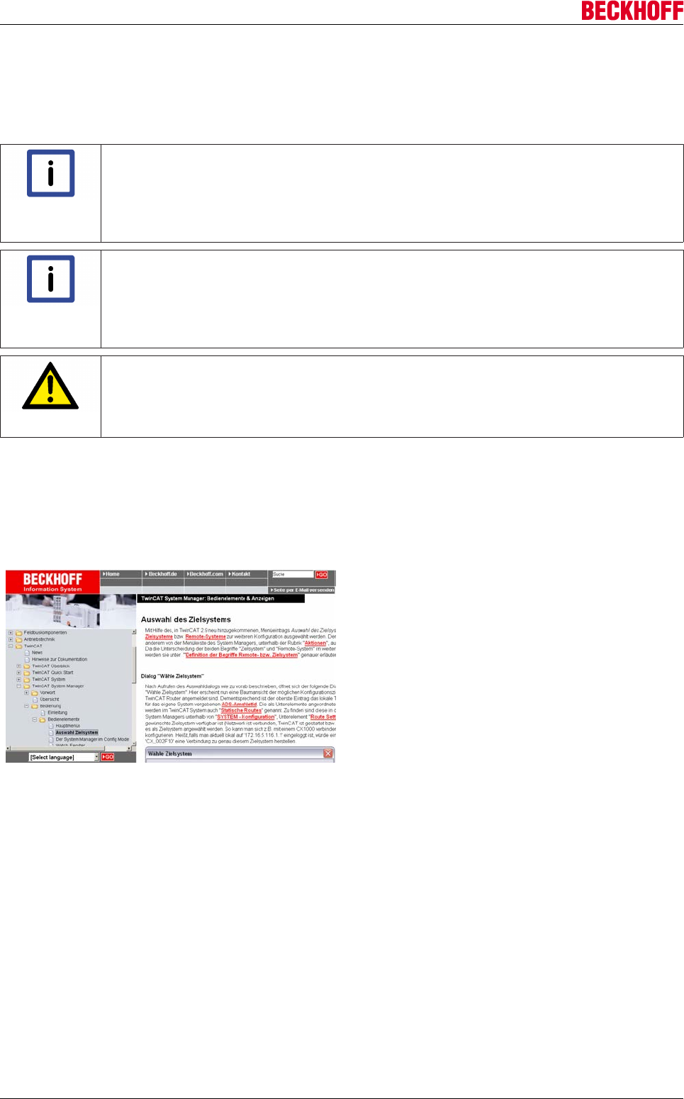
Appendix
Servo Drives AX5000264 Version: 2.4
13.2.2 Update to a new firmware version
Read please the Release Notes carefully before the update. All important changes and additions to the
individual firmware versions for the servo drives are located in the corresponding file in the download area on
our homepage.
Note
Never touch a running system!
This old IT concept applies more than ever today, in these times of the most complex sys-
tems with ever decreasing cycle times. Please do not perform firmware updates on a sys-
tem that is working well without a reason, unless requested to do so by Beckhoff Automa-
tion.
Note
Update only within a version number!
We recommend firmware updates only within the same version number (e.g.: V.1.05 (Build
0003) to V.1.05 (Build 0007). If you want to update from V.1.05 to V.1.06, for example, you
would need to make further adjustments in TwinCAT. In accompaniment to that, we do not
recommend performing a so-called "downgrade" to a lower version number.
CAUTION
Do not work on live equipment!
The 24 V supply (plug "X03") must be connected to the servo drive in order to be able to
perform a firmware update. Make sure that the power supply (plug "X01") is disconnected
from the servo drive, so that uncontrolled movements of the equipment cannot occur.
13.2.2.1 Update preparation
So that you can perform a firmware update, a connection must be made to the computer with TwinCAT that
controls the AX5000. It is quite usual for you not to be in the area where the equipment is operated. That is
not also necessary, because there are three different procedures for establishing a connection:
Direct accesses to the control computer
You are in the same place where the equipment is
operated and can work directly on the control
computer. In this case you can continue immediately
with the next chapter "Performing the update".
Remote access to the control computer
You are in a different place and have no direct
access to the control computer. In this case you can
also perform a firmware update on the control
computer using one of the remote connections (VPN
tunnel with remote desktop, VNC etc.) that are usual
in the IT world. Please make sure that the firewall is
configured accordingly for the remote connection and
that you have the necessary rights. After establishing
the remote connection you can continue with the next
chapter "Performing the update".
Remote access by ADS
You are in a different place and have no direct access to the control computer, or the control computer is
located in a cleanroom or the like. In this case you can also perform a firmware update via remote access by
ADS. Please read in the Online Information System how to implement remote access by ADS. Afterwards
you can continue with the chapter "Performing the update". The Online Information System is multilingual!
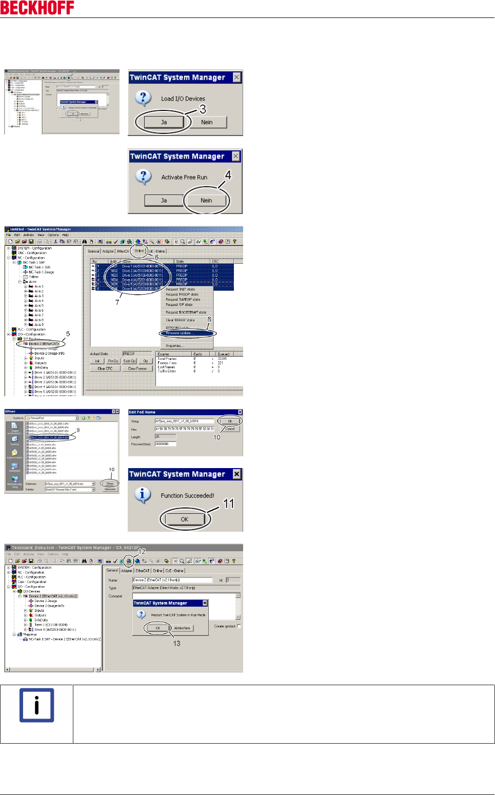
Appendix
Servo Drives AX5000 265
Version: 2.4
13.2.2.2 Performing the update
Click the button (1) in the TwinCAT System Manager
to enter the configuration mode. Confirm the query
with OK (2). After that a further window appears
which must be confirmed with Yes (Ja) (3).
Deactivate the "Free Run" with No (Nein) (4).
The system is now in "Configuration mode".
In order to perform the firmware update, you must
click the "Online" tab (6) in the "EtherCAT
Device" (5). If you want to update several devices,
you can select the respective servo drives (7)
together; in the case of one device, select only the
one servo drive. Subsequently, click with the right
mouse button inside the selected area and select the
command "Firmware Update" (8) in the command
overview.
In the place where you have stored the desired
firmware version, select the firmware file (9) and click
"Open" (10). Confirm the window that then opens with
"OK"; the firmware update is then performed. After
successful completion you must click OK (11) in the
concluding "Function Succeeded" window.
Subsequently, TwinCAT must be brought from
configuration mode back into operation mode. To do
this, click the button (12) and confirm the query that
appears with "OK" (13).
Note
Update failed!
If the firmware update is aborted with an error message, you should try again. If the abor-
tion occurs several times, please start a further attempt with another copy of the firmware
file.

Support and Service
Servo Drives AX5000266 Version: 2.4
14 Support and Service
Beckhoff and their partners around the world offer comprehensive support and service, making available fast
and competent assistance with all questions related to Beckhoff products and system solutions.
Beckhoff's branch offices and representatives
Please contact your Beckhoff branch office or representative for local support and service on Beckhoff
products!
The addresses of Beckhoff's branch offices and representatives round the world can be found on her internet
pages:
http://www.beckhoff.com
You will also find further documentation for Beckhoff components there.
Beckhoff Headquarters
Beckhoff Automation GmbH & Co. KG
Huelshorstweg 20
33415 Verl
Germany
Phone: +49(0)5246/963-0
Fax: +49(0)5246/963-198
e-mail: info@beckhoff.com
Beckhoff Support
Support offers you comprehensive technical assistance, helping you not only with the application of
individual Beckhoff products, but also with other, wide-ranging services:
• support
• design, programming and commissioning of complex automation systems
• and extensive training program for Beckhoff system components
Hotline: +49(0)5246/963-157
Fax: +49(0)5246/963-9157
e-mail: support@beckhoff.com
Beckhoff Service
The Beckhoff Service Center supports you in all matters of after-sales service:
• on-site service
• repair service
• spare parts service
• hotline service
Hotline: +49(0)5246/963-460
Fax: +49(0)5246/963-479
e-mail: service@beckhoff.com
