Bt Fd101 Fast Rolling Door Of Control Receiver Function Operation Manual
User Manual: Pdf
Open the PDF directly: View PDF ![]() .
.
Page Count: 7

Page 17
BTFD101Fastrollingdoorofcontrolreceiverfunction
operationmanual
Ⅰ‧Receiverfunction
1. A transmitter can prevent copy function, the code have million sets. The receiver
memorizescapacityofthe2000transmitters.
2. Usetransmitterstocontrolreceiverhavetwoways.Oneis4keystocontrolreceiver.
Theotheris1key(recyclemode)tocontrolreceiver.
3. Receiver builtin theft proof alarm function. Add a reed switch and alarm system.
Whilerolling dooris on top, press an OFFkey of transmitter, the receiver will into
theftproofmode.Iftherollingdoorisabnormalopened,willdrivebeeps.
4. Receiverprovides2methodsinlighter.OneisaddedunderDC24V10Woflighterin
receiver. Anotheris added a 24V relay to control existent lighter in garage.While
rollingdoorisrunning,thelighterwillbrighten.
5. Protection function:the rolling door touch obstructer will up or stop while it is
running.
6. Choose attached charge board and storage battery for charging in normal time.
Whilepoweroutage,thestoragebatterywillsupplypowertoworkinrollingdoor.
7. Providedrivingoutputintrafficsignal.AddarelaythatNCswitchconnectgreenlight
and NO switch connect red light. While the rolling door is opening or closing will
showthetrafficsignal.
8. Settime(maxto127seconds)todownfunction:therollingdoorontopwillcount
thetime,aftertimeisup,therollingdoorwillautomaticdown.
Ⅱ‧Settime(maxto127seconds)todown
1. SwitchoffSW31,SW32andSW33onthereceiver.
2. Aftertherollingdoorontop,pressOFFkeyoftransmitterintopoweroffmode.
3. Startsettimetodown–switchonSW32inthereceiver,theneachbeep1second,
count beep for necessary downing time (max to 127 seconds). After counts
necessary downing time, switch off SW32, receiver memory necessary downing
timeandstopbeep.
4. Relieve downing time – switch on SW32 in the receiver, then each beep in 1
second.Lessthan4secondsswitchoffSW32,receiverclearthedowningtimeand
stopbeep.
Ⅲ‧Resettransmittercodeandaddtransmitters
i. Learnfirsttransmittercode:
1. Losepowerofthereceiverover15seconds;prepareatransmitter.
2. PoweronthereceiverandpressSW1ofreceiverunder10seconds,startbeepthat
into learning code mode, synchronous press UP and DOWN key of transmitter
under10seconds,afterreceivergotthesignalwillcleanformercode,memorythis
transmittercode,andstopbeepandquitlearningmode.
ii. Addothertransmittercode:
1. Prepareoriginaltransmitterandnewtransmitters.
2. SynchronouspressSTOPandOFFkeyoforiginaltransmitter,receivewillbeepthat
intoaddtransmittercodemode.
3. SynchronouspressUPandDOWNkeyofnewtransmitterunderbeeps10seconds,
after receiver got the signal will memory new transmitter code. Add other

Page 27
transmitterscodewillrecount10seconds. If did not add transmitter code wi ll
beepandquitthelearningcodemode.
Ⅳ‧Remotecontrolreceivermethodbytransmitter
i. Remotecontrolmodeby4keysoftransmitter:(Seeillustration4inpage
5)
1. SwitchoffSW33inreceiverboard,4keysoftransmittercanremotecontrolreceiver.
2. On4keysoftransmittermode,setSW31andSW32functionastable:
SW 31SW 32 SW 33 FUNCTION
OFF OFF OFF
PressOFFkeyoftransmitter,receiverdon’tacceptmanual
switch control, and also don’t accept UP and DOWN of
transmitter. We called “power off mode” in this operation
manual.
ON OFF OFF Press OFF key of transmitter, receiver accept manual
switchandtransmittercontrol.
OFF ON OFF Setnecessarydowningtime:autocountdown.
ii. 1keyoftransmitterremotecontrolmode(1keyrecyclemode):
1. SwitchonSW33onthereceiverboard,1keyoftransmitterinremotecontrolmode;
receiverwascoercedsetpoweroffmode.
2. SW31andSW32weresetwhichkeyoftransmittertocontrolreceiverastable:
SW 31 SW 3
2
SW 33 FUNCTION
ON OFF ON UP key of transmitter to control receiver. (UP key recycle
mode)
OFF ON ON STOP key of transmitter to control receiver. (STOP key
recyclemode)
ON ON ON DOWN key of transmitter to control receiver. (DOWN key
recyclemode)
OFF OFF ON OFFkeyoftransmittertocontrolreceiver.(OFFkeyrecycle
mode)
3. In1keyoftransmittermode,4keysoftransmittercancontrol4receivers.
4. Remotecontrol2receiversby1transmitter.OnereceiveradjustSW31ON,SW32
OFF,SW33OFF,cancontrolreceiverbyUP andSTOPandDOWNoftransmitter.
Another receiveradjustSW31 OFF,SW32OFF,SW33ON, cancontrolreceiver
byOFFkeyoftransmitter(recyclemode).
iii. Noticeitem:
1. Codetransportationmethodbywirelesstransmit,eachreceiverswillreceivesignal
whilesetcode.Whensharedatransmitterinpublicandindividualguard,attention
orderandmethodsincodelearning.
2. Set remote controller in individual and public guard. Prior set code learning in
individualguard,thenaddtransmittercodeinpublicguard.
3. Thefirsttransmitterkeepwellinpublicguard,forwardaddtransmittersneedthefirst
transmitterintothecodelearningmodeinthereceiver.
Ⅴ‧Alarmandreedswitchofwiringandfunction
i. Wiring:
Page 37
1. Terminal M and V connect to reed switch, set reed switch in rolling door bottom.
(Seeillustration6inpage6)
2. ProvideNC/NOswitchofalarmoutputtoterminalCNT5ofthereceiverboard,ON
andOFFofNC/NOswitchtocontrolbeepinalarm.(Seeillustration1inpage4)
ii. Function:
1. Theftproofmode:whilerollingdoorisonbottom,receiverchecksifhavethesignal
ofreedswitch,ifthereceiveracceptssignalwillintothetheftproofmode.Whenthe
rollingdoorwasopeneddidnotthroughmanualswitchorremotecontroller,receiver
willdrivealarmtobeepuntilrid.
2. Ridbeep:whilebeepinalarm,pressanykeyoftransmittercanridbeep.
Ⅵ‧Typeandwiringofaccessoryboard
i. Accessoryboardtype:
1. Chargeboard–wireconnectfromUPSmarkofthereceiverboardtochargeboard.
Then wire connects from charge board to the storage battery. Receiver board
chargepowertothestoragebatteryincommontime.Whilelosepowerthestorage
batteryprovidespowertoreceiverboard.(Seeillustration10inpage7)
2. Trafficlightscontrolboard–connectwirefromCNT4onthereceiverboardtotraffic
lightscontrolboardthatprovide2pairsterminals,followdirectionconnecttogreen
lamp and red lamp. Another two orange wires are input power on the traffic lights
control board. 2 orange wires connect with adapter. Notice the receiver supply
voltageisAC220V,trafficlightsmustuseAC220V;ifsupplyvoltageisAC110V,and
trafficlightsmustuseAC110V.Sotrafficlightscontrolboardisaccordingrollingdoor
openingorclosingtoshowtrafficlightssignal.Whilerollingdoorisopeningwillturn
on the red lamp, while rolling door is closing will turn on the green lamp. (See
illustration2inpage5)
3. ConnectInteriorlamp:provideterminalconnectlamp.(Seeillustration3inpage5)
Ⅶ‧Connectwiringofinferredsignal
i. Connectinferredsignal:
1. Purpose: while rolling door is downing or stop, if the inferred sensor detected
something,therollingdoorwillautoup.
2. Receiver board provides E and V of terminal to connect N.O. switch of inferred
sensor.(Seeillustration6inpage6)
Page 47
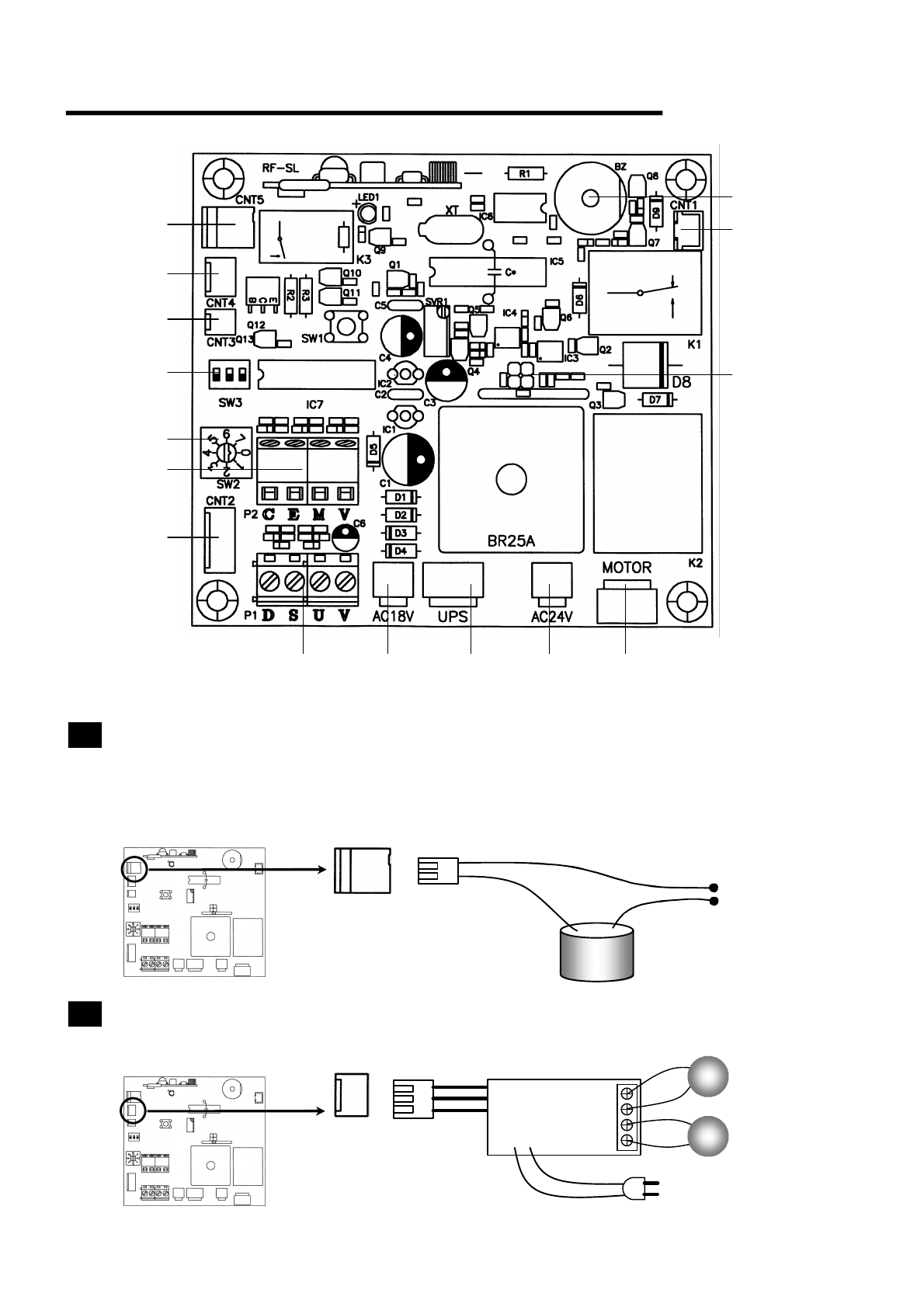
Wiresconnectionillustration
1Alarmconnection—Collocatewithreedswitch(Seeillustration6).When
rollingdoorclosedatbottom,pressOFFkeyoftransmitter,receiverenter
antithief mode. After into antithief mode, if rolling door didn’t open by
manualswitchortransmitter,receiverdrovealarmtobeeps.
2Connect traffic lights control board—Red lamp lights on when rolling
dooropens,greenlamplightsonwhenrollingdoordown.
1
2
3
6
7
8 9 10 11 12
13
14
4
5
Inputpower
ALARM
Redlight
Lightpowerline
Greenlight
15
Page 57
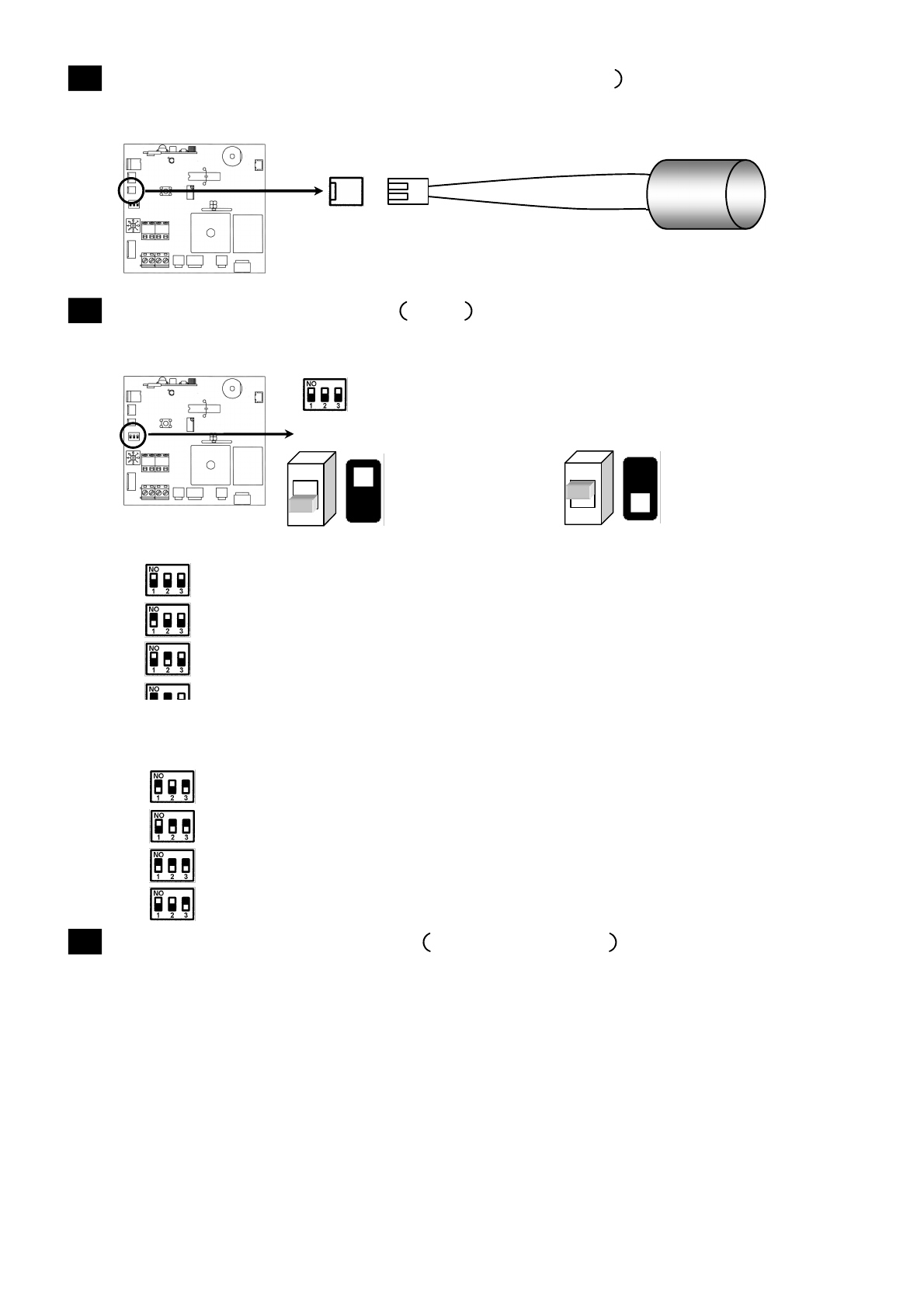
3Connect interior lamp(DC24V/10W output —Receiver makes
illumininglightonwhenrollingdoorisrunning.
4Function selected switch SW3 —setting transmitter: 4keys control
receiveroronekeycontrolreceiver.
4keyscontrolmode—
Press OFF key of transmitter, receiver don’t accept manual switch control,
andalsodon’tacceptUPandDOWNoftransmitter.
PressOFFkeyoftransmitter,receiveracceptmanualswitchandtransmitter
control.
Timingdownautomatically,settingtimemode.
Onekeyrecyclecontrolmode—
Receivercontrolledbylauncher’s“up”key.
Receivercontrolledbylauncher’s“stop”key.
Receivercontrolledbylauncher’s“down”key.
Receivercontrolledbylauncher’s“off”key.
5Obstructionselectedswitch SW207section —whenrollingdooris
running and touched obstruction, it can go up or stop. This selection
switch can set the obstructed strength. More value indicates bigger
obstruction.
Interior
lamp ð
Forwardtoyourself
putswitchtodown,
represent:OFF
Forwardtoyourself
putswitchtoup,
represent:ON
※SwitchSW33OFF:4keysoftransmittertocontrol.
※SwitchSW33ON:onekeyoftransmittertocontrol.
Page 67
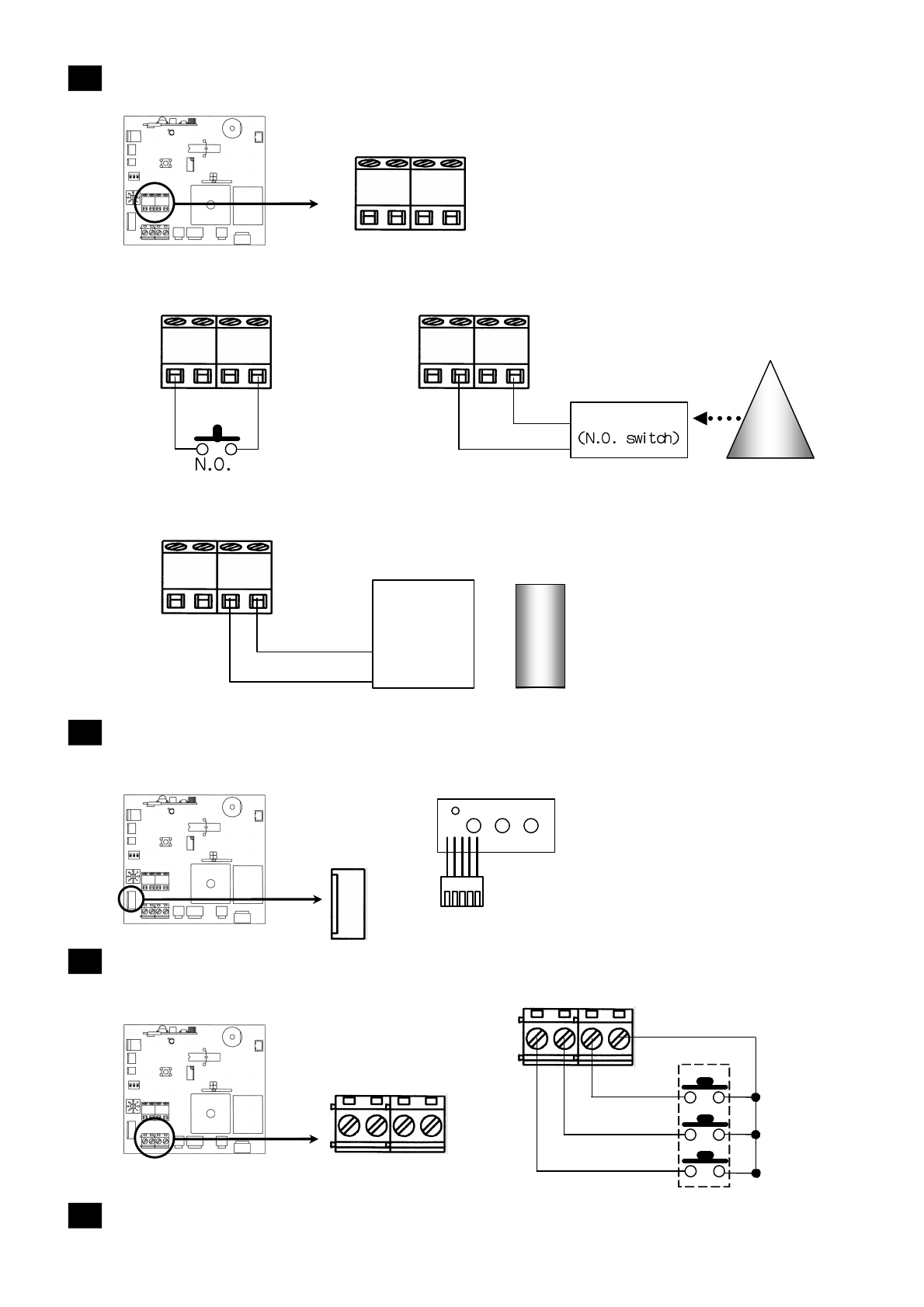
6Connectionof1keyrecyclecontrol,infraredsensor,reedswitch—
Reedswitch
7Connectmanualswitch,controlboardofpowerinstructionlight(Set
receiver’scoverininside)—
8Connectmanualswitchinoutside—Ifreceiver at afar place, you can
connectmanualswitchinoutside.
9AC18Vinputend—AC18Voutputoftransformerconnectatthispoint.
C E
M
V
C E
M
V
Connectway1: 1
keyrecyclecontrol
Connectway2:
infraredsensor
C E
M
V
Infrared
signal
Infrared receiver
Connectway3:
Reedswitch
C E M V Induced
(N.C.
switch)
~
~
~
D S U V
D S U V UP
STOP
DOWN
OUTSIDESWITCH
Magnet
Page 77
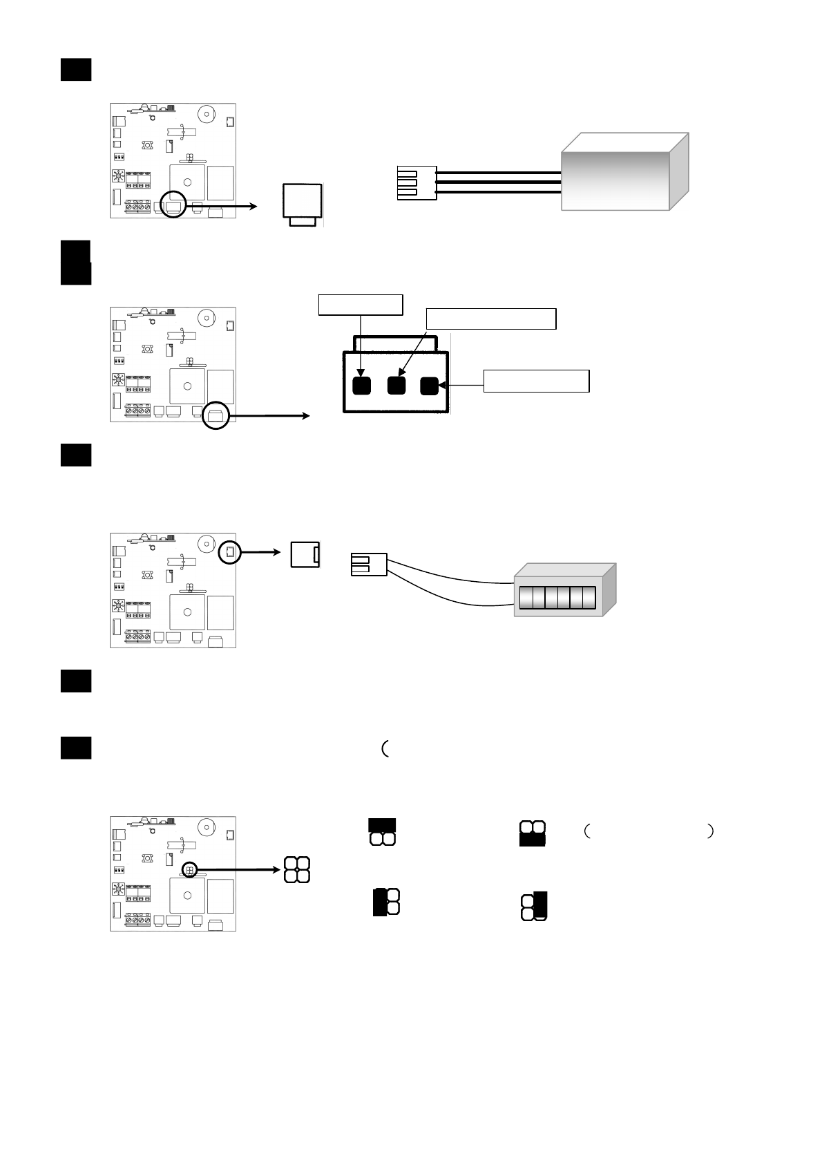
10UPS—UPSterminalconnecttoreceiverboard.
11AC24Vinputend—AC24Voutputoftransformerconnectatthispoint.
12ConnectMOTORtoreceiverboard.
13Connect counter (DC24V) to receiver board—After connected with
DC24V counter, it count the number of times during rolling door is
running.Countonetimeduringmotorisopeningorclosing.
14Beeper(used in setting mode selection, function setting, condition
instruction)—know when will beep, please see receiver’s function
operationmanual.
15Switch of multiple magnify Current degree big – small, modify
switchofmultiplemagnify(○
4>○
3>○
2 >○
1)—
EX1: Slat of roller door is more big or more heavy, load current will
bigger, need modify switch of multiple magnify to next number (if switch
on ,turnto )
EX2:Slatofrollerdoorissmallerorlighter,loadcurrentwillsmaller,need
modifyswitchofmultiplemagnifytoundernumber(ifswitchon ,turnto
)
UPS
(Storagebattery+
chargeboard)
888888
DC24V
UP(Black) Common(Green)
Down(White)
○
1 ○
2
○
3 ○
4
Bigger Big Manufactoryset
Medium Small
