P605 Nj Series Ethercat Fanuc R 30ib Robot Controller Connection Guide En
User Manual: Pdf
Open the PDF directly: View PDF ![]() .
.
Page Count: 44
- 1. Related Manuals
- 2. Terms and Definitions
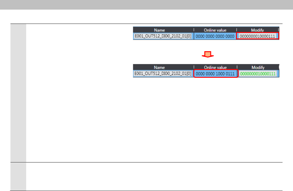
- 3. Precautions
- 4. Overview
- 5. Applicable Devices and Device Configuration
- 6. EtherCAT Settings
- 7. EtherCAT Connection Procedure
- 8. Initialization Method
- 9. Revision History
Machine Automation Controller NJ-series
EtherCAT(R)
Connection Guide
FANUC CORPORATION
R-30iB Robot Controller
P605-E1-01

About Intellectual Property Rights and Trademarks
Microsoft product screen shots reprinted with permission from Microsoft Corporation.
Windows is a registered trademark of Microsoft Corporation in the USA and other countries.
EtherCAT(R)
is registered trademark and patented technology, licensed by Beckhoff Automation
GmbH, Germany.
Sysmac is a trademark or registered trademark of OMRON Corporation in Japan and other
countries for OMRON factory automation products.
Company names and product names in this document are the trademarks or registered
trademarks of their respective companies.

Table of Contents
1. Related Manuals .......................................................................................... 1
2. Terms and Definitions ................................................................................. 2
3. Precautions .................................................................................................. 3
4. Overview ...................................................................................................... 4
5. Applicable Devices and Device Configuration ........................................ 4
5.1. Applicable Devices .............................................................................. 4
5.2. Device Configuration ........................................................................... 5
6. EtherCAT Settings ....................................................................................... 7
6.1. Setting Up the Robot Controller .......................................................... 7
6.2. Allocation for PDO Communications ................................................... 8
7. EtherCAT Connection Procedure ............................................................ 10
7.1. Work Flow .......................................................................................... 10
7.2. Setting Up the FANUC Robot Controller ............................................ 11
7.3. Setting Up the Controller ................................................................... 20
7.4. Checking the EtherCAT Communications ......................................... 32
8. Initialization Method .................................................................................. 38
8.1. Initializing the Controller .................................................................... 38
8.2. Initializing the FANUC Robot Controller ............................................ 38
9. Revision History ........................................................................................ 39
1
.
Related Manuals
1
1. Related Manuals
The table below lists the manuals related to this document.
To ensure system safety, make sure to always read and heed the information provided in all
Safety Precautions, Precautions for Safe Use, and Precaution for Correct Use of manuals for
each device which is used in the system.
Cat. No. Model Manual name
W500 NJ501-[][][][]
NJ301-[][][][]
NJ-series CPU Unit Hardware User's Manual
W501 NJ501-[][][][]
NJ301-[][][][]
NJ-series CPU Unit Software User's Manual
W505 NJ501-[][][][]
NJ301-[][][][]
NJ-series CPU Unit Built-in EtherCAT(R) Port User's Manual
W504 SYSMAC-SE2[][][] Sysmac Studio Version 1 Operation Manual
B-83284EN R-30iB FANUC Robot series R-30iB/R-30iB Mate CONTROLLER
OPERATOR’S MANUAL(Basic Operation)
B-83704EN R-30iB FANUC Robot series R-30iB/R-30iB Mate CONTROLLER
EtherCAT Interface OPERATOR’S MANUAL

2
.
Terms and Definitions
2
2. Terms and Definitions
Term Explanation and Definition
PDO
Communications
(Communications
using Process
Data Objects)
This method is used for cyclic data exchange between the master unit and
the slave units.
PDO data (i.e., I/O data that is mapped to PDOs) that is allocated in
advance is refreshed periodically each EtherCAT process data
communications cycle (i.e., the period of primary periodic task).
The NJ-series Machine Automation Controller uses the PDO
Communications for commands to refresh I/O data in a fixed control
period, including I/O data for EtherCAT Slave Units, and the position
control data for the Servomotors.
It is accessed from the NJ-series Machine Automation Controller in the
following ways.
・With device variables for EtherCAT slave I/O
・With Axis Variables for Servo Drive and encoder input slave to which
assigned as an axis
SDO
Communications
(Communications
using Service
Data Objects)
This method is used to read and write the specified slave unit data from
the master unit when required.
The NJ-series Machine Automation Controller uses SDO Communications
for commands to read and write data, such as for parameter transfers, at
specified times.
The NJ-series Machine Automation Controller can read/write the specified
slave data (parameters and error information, etc.) with the
EC_CoESDORead (Read CoE SDO) instruction or the EC_CoESDOWrite
(Write CoE SDO) instruction.
Slave unit There are various types of slaves such as Servo Drives that handle
position data and I/O terminals that handle the bit signals.
The slave unit receives output data sent from the master, and sends input
data to the master.
Node address A node address is an address to identify a unit connected to EtherCAT.
ESI file
(EtherCAT Slave
Information file)
The ESI files contain information unique to the EtherCAT slaves in XML
format.
Installing an ESI file enables the Sysmac Studio to allocate slave process
data and make other settings.
UOP Peripheral I/O (UI/UO) is a group of specialized signals for robot control.
Digital I/O Digital I/O (DI/DO) is a group of general-purpose digital signals for data
exchange with peripheral equipments.

3
.
Precautions
3
3. Precautions
(1) Understand the specifications of devices which are used in the system. Allow some
margin for ratings and performance. Provide safety measures, such as installing safety
circuit in order to ensure safety and minimize risks of abnormal occurrence.
(2) To ensure system safety, always read and heed the information provided in all Safety
Precautions and Precautions for Safe Use of manuals for each device used in the
system.
(3) The user is encouraged to confirm the standards and regulations that the system must
conform to.
(4) It is prohibited to copy, to reproduce, and to distribute a part or the whole of this
document without the permission of OMRON Corporation.
(5) The information contained in this document is current as of August 2014. It is subject to
change without notice for improvement.
The following notations are used in this document.
Indicates a potentially hazardous situation which, if not
avoided, will result in minor or moderate injury, or may
result in serious injury or death. Additionally there may be
significant property damage.
Indicates a potentially hazardous situation which, if not
avoided, may result in minor or moderate injury or property
damage.
Precautions for Safe Use
Precautions on what to do and what not to do to ensure safe usage of the product.
Precautions for Correct Use
Precautions on what to do and what not to do to ensure proper operation and performance.
Additional Information
Additional information to read as required.
This information is provided to increase understanding or make operation easier.
Symbol
The filled circle symbol indicates operations that you must do.
The specific operation is shown in the circle and explained in text.
This example shows a general precaution for something that must do.
4
.
Overview
4
4. Overview
This document describes the procedure for connecting Robot Controller (R-30iB) of FANUC
Corporation (hereinafter referred to as FANUC) to NJ-series Machine Automation Controller
(hereinafter referred to as Controller) of OMRON Corporation (hereinafter referred to as
OMRON) via EtherCAT and provides the procedure for checking their connection.
Refer to Section 6 EtherCAT Settings and Section 7 EtherCAT Connection Procedure to
understand the setting method and key points to operate PDO Communications of EtherCAT.
5. Applicable Devices and Device Configuration
5.1. Applicable Devices
The applicable devices are as follows:
Manufacturer Name Model
OMRON
NJ-series CPU Unit
NJ501-[][][][]
NJ301-[][][][]
FANUC
Robot Controller
R-30iB (with optional EtherCAT slave function)
FANUC
Robot
Refer to the following Additional Information.
Precautions for Correct Use
As applicable devices above, the devices with the models and versions listed in Section 5.2.
are actually used in this document to describe the procedure for connecting devices and
checking the connection.
You cannot use devices with versions lower than the versions listed in Section 5.2.
To use the above devices with versions not listed in Section 5.2 or versions higher than those
listed in Section 5.2, check the differences in the specifications by referring to the manuals
before operating the devices.
Additional Information
Contact sales representatives of FANUC Corporation for robots connectable to the Robot
Controller.
Additional Information
This document describes the procedure to establish the network connection. It does not
provide information on operation, installation or wiring method which is not related to the
connection procedure. It also does not describe the functionality or operation of the devices.
Refer to the manuals or contact the device manufacturer.
(FANUC Corporation http://www.fanuc.co.jp/eindex.htm)
This URL is the latest address at the time of this document creation.
Contact each device manufacturer for the latest information.
5
.
Applicable Devices and Device Configuration
5
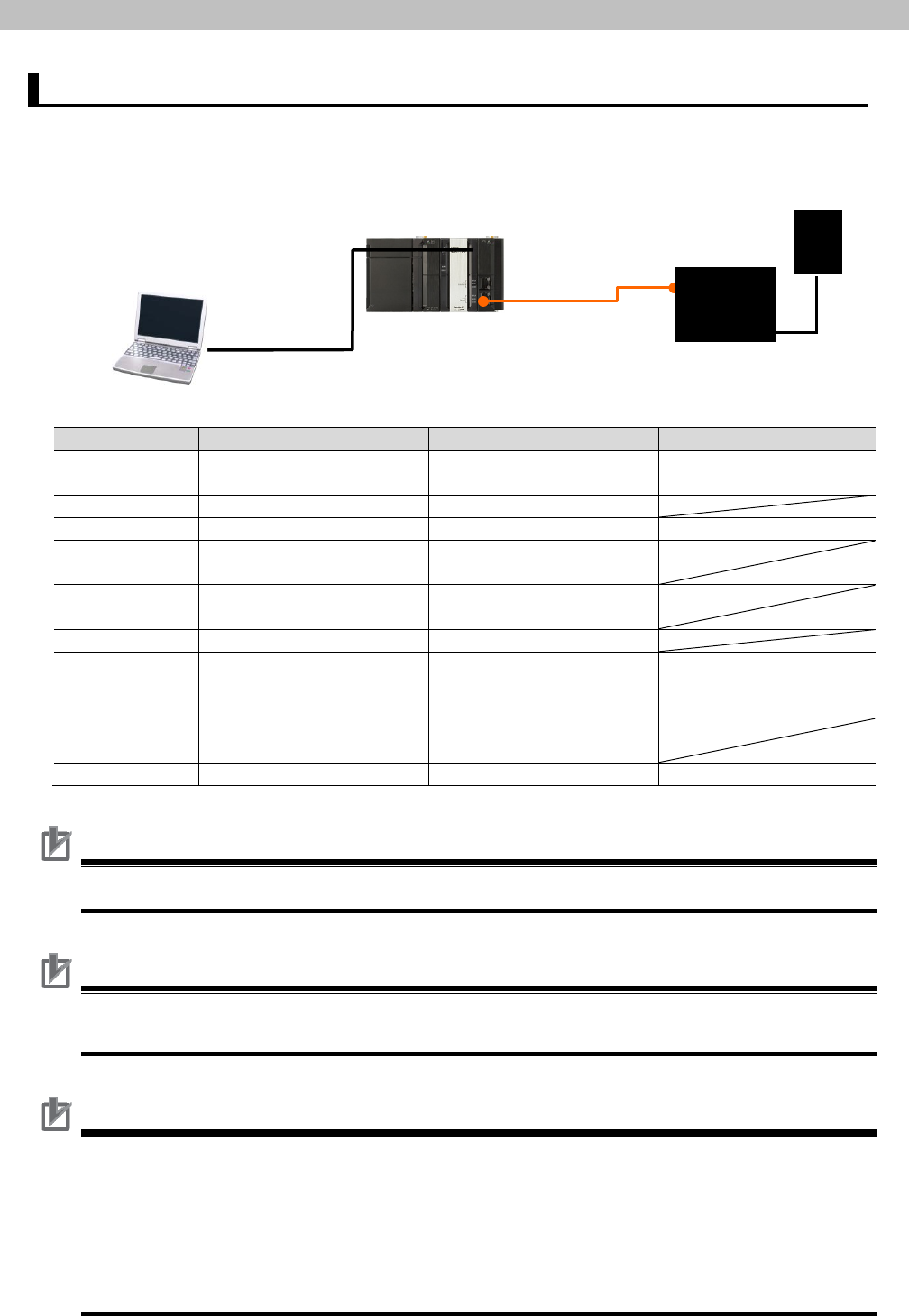
5.2. Device Configuration
The hardware components to reproduce the connection procedure of this document are as
follows:
Manufacturer
Name
Model
Version
OMRON
CPU Unit
(Built-in EtherCAT port)
NJ501-1500
Ver.1.08
OMRON
Power Supply Unit
NJ-PA3001
OMRON
Sysmac Studio
SYSMAC-SE2[][][]
Ver.1.09
-
Personal computer
(OS: Windows7)
-
-
USB cable (USB 2.0 type
B connector)
-
-
Ethernet cable
-
FANUC Robot Controller
R-30iB (with optional
EtherCAT slave function)
7DC2 series
(ver.11 or higher),
7DC3 series
FANUC
Teach pendant
(Included with Robot
Controller)
FANUC
ESI file
fanuc_rs_esi0001.xml
0x0001
Precautions for Correct Use
The ESI file “ver. 0x0001” shown above is used in this document to check the operations.
Precautions for Correct Use
Prepare the ESI file shown in this section beforehand.
To obtain the ESI file, contact FANUC.
Precautions for Correct Use
The connection line of EtherCAT communication cannot be shared with other Ethernet
networks.
Do not use devices for Ethernet such as a switching hub.
Use the cable (double shielding with aluminum tape and braiding) of Category 5 or higher,
and use the shielded connector of Category 5 or higher.
Connect the cable shield to the connector hood at both ends of the cable.
USB cable
NJ501-1500
(Built-in EtherCAT port)
Ethernet cable
Personal computer
(Sysmac Studio,
installed,
OS: Windows7 )
R-30iB
Teach pendant

5
.
Applicable Devices and Device Configuration
6
Precautions for Correct Use
Update the Sysmac Studio to the version specified in this section or higher version using the
auto update function.
If a version not specified in this section is used, the procedures described in Section 7 and
subsequent sections may not be applicable. In that case, use the equivalent procedures
described in the Sysmac Studio Version 1 Operation Manual (Cat. No. W504).
Additional Information
For specifications of the Ethernet cables and network wirings, refer to Section 4 EtherCAT
Network Wiring of the NJ-series CPU Unit Built-in EtherCAT(R) Port User's Manual (Cat. No.
W505).
Additional Information
The system configuration in this document uses USB for the connection to the Controller.
For how to install a USB driver, refer to A-1 Driver Installation for Direct USB Cable
Connection of the Sysmac Studio Version 1 Operation Manual (Cat.No. W504).

6
.
EtherCAT Settings
7
6. EtherCAT Settings
This section describes specifications such as the Robot Controller setup and allocation of
PDO Communications that are set in this document. This is used to connect the Controller to
the Robot Controller via EtherCAT. Hereinafter, the Robot Controller is referred to as the
"Destination Device" or the "Slave Unit" in some descriptions.
6.1. Setting Up the Robot Controller
The setting of the Robot Controller is shown below.
Setting item Set value
Node address 1 (default)
SMODE switch (EtherCAT board switch) 0 (fixed)
Switch on the front panel of Robot Controller Three mode switch AUTO
Switches on the Teach pendant Teach pendant enable
switch
OFF (disable)*
1
Screen setting of the Teach pendant The number of input 512 points
(default)
The number of output 512 points
(default)
Remote/local setup Remote
UOP auto assignment Full *
2
(default)
*1: When the Teach pendant enable switch is disabled, the operation of the Teach pendant is
disabled. Accordingly, the Teach pendant cannot perform the jog feed, program operation,
and test execution.
*2: The “UOP auto assignment” assigns all UOPs of input 18-points and output 20-points to I/O.
When the "UOP auto assignment" is set to "Full", the Robot Controller automatically sets
the following set values of the UOP assignment.
■ UOP output
# Range Rack Slot Start
1 UO[1-8] 106 (fixed) 1 (fixed) 1
2 UO[9-16] 106 (fixed) 1 (fixed) 9
3 UO[17-20] 106 (fixed) 1 (fixed) 17
■ UOP input
# Range Rack Slot Start
1
UI[1-8]
106 (fixed)
1 (fixed)
1
2 UI[9-16] 106 (fixed) 1 (fixed) 9
3 UI[17-18] 106 (fixed) 1 (fixed) 17
Precautions for Safe Use
For explanation purpose, this document uses the settings above as an example. The user
must decide actual set values according to the application to be used after verifying its safety.
6
.
EtherCAT Settings
8
6.2. Allocation for PDO Communications
The section describes allocation of PDO Communications between the Destination Device
and the Controller.
6.2.1. Device Variables of the Controller
The PDO communications data for the Destination Device are allocated to the Controller's
device variables.
The device variables and the data types are shown below.
■ Output area (from Controller to Destination Device)
Device variable name Data type Meaning
E001_OUT512_DI00_2102_01 UINT[8] UOP inputs (UI1 to 18),
Digital inputs (DI1 to 110)
E001_OUT512_DI01_2102_02
UINT[8] Digital inputs (DI111 to 238)
E001_OUT512_DI02_2102_03 UINT[8] Digital inputs (DI239 to 366)
E001_OUT512_DI03_2102_04
UINT[8] Digital inputs (DI367 to 494)
■ Input area (from Destination Device to Controller)
Device variable name Data type Meaning
E001_IN512_DO00_3102_01 UINT[8] UOP outputs (UO1 to 20),
Digital outputs (DO1 to 108)
E001_IN512_DO01_3102_02
UINT[8] Digital outputs (DO109 to DO236)
E001_IN512_DO02_3102_03 UINT[8] Digital outputs (DO237 to DO364)
E001_IN512_DO03_3102_04
UINT[8] Digital outputs (DO365 to DO492)
Additional Information
The device variables are named automatically from a combination of the device names and
the port names.
The default device names are “E" followed by a serial number that starts from 001.
6
.
EtherCAT Settings
9
6.2.2. I/O Allocation for the Robot Controller
The I/O allocation for the Robot Controller is shown below.
Controller Robot Controller’s
EtherCAT slave
Robot Controller
Output variables
E001_OUT512_DI00_2102_01[0]
to
E001_OUT512_DI03_2102_04[7]
64 bytes *1
(512 bits)
UOP input
allocation
(18 points)
UI
*2
#1:IMSTP
#2:Hold
:
#18:PROD_START
Digital inputs
(494 points)
DI
#1
#2
:
#494
Not used Not used
#495
:
Input variables
E001_IN512_DO00_3102_01[0]
to
E001_IN512_DO03_3102_04[7]
64 bytes *1
(512 bits)
UOP output
allocation
(20 points)
UO
*2
#1:Cmd enabled
#2:System ready
:
#20:RESERVED
Digital outputs
(492 points)
DO
#1
#2
:
#492
Not used Not used
#493
:
*1: In this setting example, 64 byte-data is exchanged for each input and output areas
between the Controller and the Robot Controller’s EtherCAT slave.
*2: The “UOP auto assignment” assigns all UOPs of input 18-points and output 20-points to I/O.
Digital I/O is assigned for others.
7
.
EtherCAT Connection Procedure
10
7. EtherCAT Connection Procedure
This section describes the procedure for connecting the Controller to the Robot Controller via
EtherCAT.
This document explains the procedures for setting up the Controller and the Robot Controller
from the factory default setting. For the initialization, refer to Section 8. Initialization Method.
7.1. Work Flow
Take the following steps to perform PDO Communications of EtherCAT.
7.2. Setting Up the FANUC Robot
Controller
Set up the FANUC Robot Controller.
↓
7.2.1. Hardware Settings
Set the hardware switches on the Robot Controller
and connect the cables.
↓
7.2.2. Parameter Settings
Set the parameters for the Robot Controller.
↓
7.3. Setting Up the Controller
Set up the Controller.
↓
7.3.1. Starting the Sysmac Studio and
Installing the ESI File
Install the ESI file for the Robot Controller in the
Sysmac Studio.
↓
7.3.2. Setting Up the EtherCAT
Network Configuration
Set up the EtherCAT network configuration.
↓
7.3.3. Setting the Device Variables
Set the device variables used for the EtherCAT
Slave Unit.
↓
7.3.4. Transferring the Project Data
Transfer the project data from the Sysmac Studio to
the Controller.
↓
7.4. Checking the EtherCAT
Communications
Confirm that the PDO Communications of EtherCAT
are performed normally.
↓
7.4.1. Checking the Connection Status
Check the connection status of the EtherCAT
network.
↓
7.4.2 Checking the Data that are Sent
and Received
Confirm that the correct data are sent and received.

7
.
EtherCAT Connection Procedure
11
7.2. Setting Up the FANUC Robot Controller
Set up the FANUC Robot Controller.
7.2.1. Hardware Settings
Set the hardware switches on the Robot Controller and connect the cables.
Precautions for Safe Use
Make sure that the power supply to the Robot Controller is OFF before opening its front
panel. Touching the internal board may result in electric shock or equipment damage while
the power is being supplied.
1
Make sure that the power
supply to the Robot Controller is
OFF.
*Step 3 in this section is
potentially hazardous that may
result in electric shock or
equipment damage.
For safety, be sure to unplug
the Power supply cable from
the power supply source.
2
Check the position of the
connectors and switches on the
Robot Controller.
(Front panel of Robot Controller)
Emergency stop
Start
Alarm release
Power switch
Three mode switch
7
.
EtherCAT Connection Procedure
12
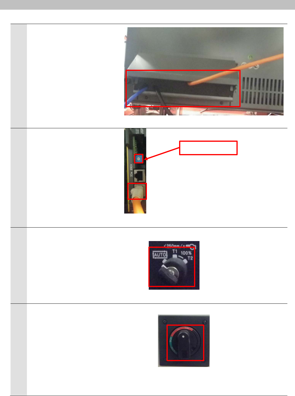
3
Open the front panel of the
Robot Controller.
Insert the Ethernet cable from
the wiring outlet located in the
lower left of the rear panel on
the Robot Controller, and pull
out the cable toward the front
panel.
(Lower left of the rear panel on Robot Controller)
4
Connect the Ethernet cable to
the IN side of the connector on
the EtherCAT board.
Confirm that the SMODE switch
on the EtherCAT board is 0.
Close the front panel.
*For safety, after wiring has
been completed, be sure to
close the front panel before
performing the subsequent
steps.
(EtherCAT board)
5
Set the Three mode switch on
the Robot Controller to the
AUTO side.
(Three mode switch)
6
Turn ON the Power switch on
the Robot Controller to supply
power.
* After power ON, a message
appears indicating the
initialization is being processed
on the connected Teach
pendant. Then the operation
screen is displayed.
Do not start operation until the
operation screen has been
displayed.
ON
OFF
(Power switch)
OUT
IN
SMODE switch
AUTO
T1
T2
7
.
EtherCAT Connection Procedure
13
7.2.2. Parameter Settings
Set the parameters for the Robot Controller.
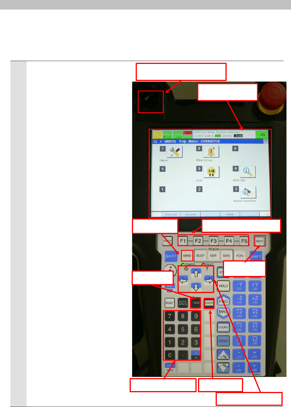
1
The following switch and keys are
used to operate the Teach pendant.
(Refer to the right figure.)
・Switch
Teach pendant enable switch
・Keys
Function (F) keys: F1 to 5, NEXT
key, MENU key, Cursor keys
(arrows), ITEM key, ENTER key,
and Numeric keys: 0 to 9.
(Teach pendant)
Teach pendant enable switch
Function (F) keys: F1 to 5
ITEM key
Operation screen
Cursor keys (arrows)
Numeric keys: 0 to 9
ENTER key
MENU key
NEXT key

7
.
EtherCAT Connection Procedure
14
2
Turn OFF (disable) the Teach
pendant enable switch on the Teach
pendant.
OFF ON
(Upper left of Teach pendant)
3
Press the MENU key on the Teach
pendant.
*After power ON, a message
appears indicating the initialization
is being processed. Then, the
operation screen that was
displayed before power OFF
appears.
Do not start operation until the
operation screen has been
displayed.
4
Select 6 SETUP from the MENU 1
Menu and select EtherCAT with the
cursor key.
Press the ENTER key.
* The above setting operation can
be executed whatever type of
configuration is displayed on the
screen.
5
The SETUP EtherCAT Screen is
displayed.
Confirm that the settings are made
as follows:
The number of input: 512 points
The number of output: 512 points
*If any change is made to the
setting, cycle the power supply.
After restarting, the changes
become available.
7
.
EtherCAT Connection Procedure
15
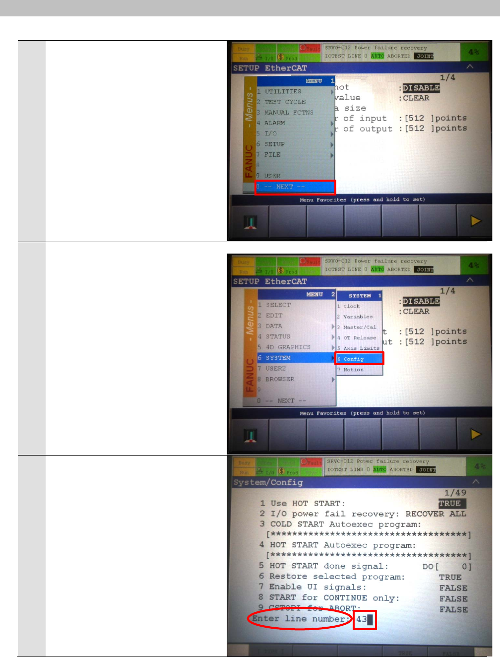
6
Press the MENU key on the Teach
pendant.
Select 0 --NEXT-- from the MENU 1
Menu with the cursor key.
Press the ENTER key.
7
Confirm that the screen changes to
MENU 2.
Select 6 SYSTEM – 6 Config from
the MENU 2 Menu with the cursor
key.
Press the ENTER key.
8
The System/Config Screen is
displayed.
Press the ITEM key on the Teach
pendant to display " Enter line
number".
Enter 43 to display "43
Remote/Local setup".
Press the ENTER key.
7
.
EtherCAT Connection Procedure
16
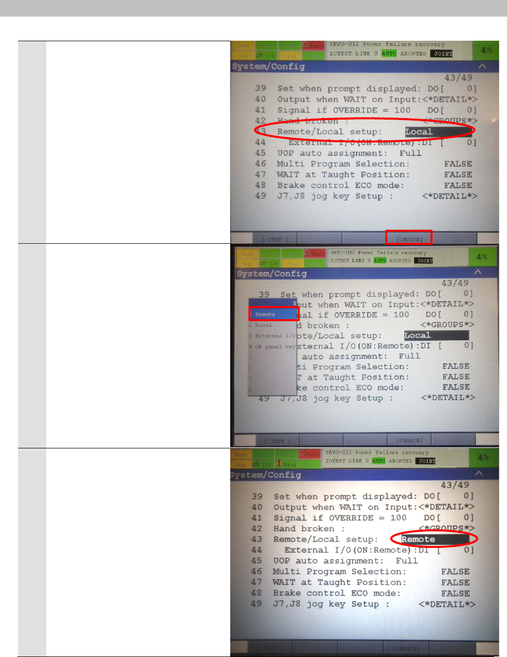
9
The cursor moves to "43
Remote/Local setup".
Press the F4 key (CHOICE).
10
A screen menu is displayed.
Select 1 Remote with the cursor
key.
Press the ENTER key.
11
Confirm that "43 Remote/Local
setup" changes to Remote.

7
.
EtherCAT Connection Procedure
17
12
Move the cursor to "45 UOP auto
assignment" with the cursor key.
Confirm that Full is indicated.
(Additional information)
* Assign I/O by changing the setting
of "45 UOP auto assignment".
Press the F4 key (CHOICE) to
display a screen menu and select 2
Full.
*"45 UOP auto assignment" indic
ates Full.
A message appears indicating
“Clear ALL I/O assignments to
Apply this?".
Check the contents and press the
F4 key (CHOICE) to delete all the
I/O assignments.
*A message appears indicating
"Cycle power to apply new UOP
assignment".
Cycling the power supply.
After power ON, UOP is
automatically assigned according to
the setting.
After restarting, the System/Config
Screen is displayed.
Perform step 13.
(Additional information)
When assigning I/O by changing the setting of "45 UOP
auto assignment".
7
.
EtherCAT Connection Procedure
18
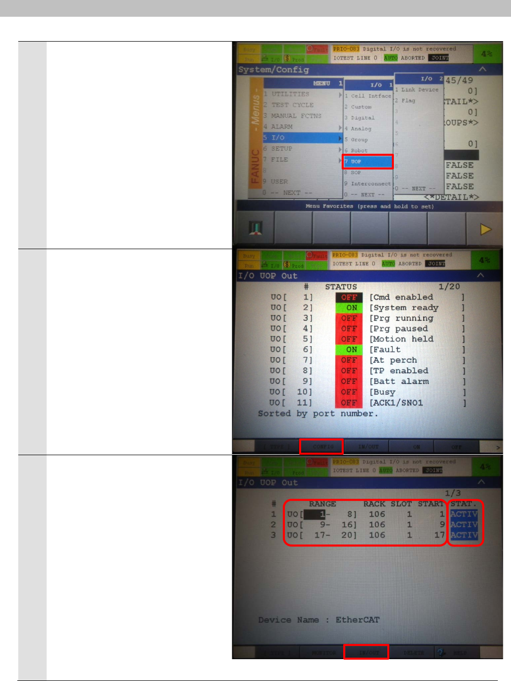
13
Select 5 I/O - 7 UOP from the
MENU 1 Menu with the cursor key.
Press the ENTER key.
14
The I/O UOP Out Screen is
displayed.
Press the F2 key (CONFIG).
15
The I/O UOP Out Screen is
displayed for assignment.
Confirm that the following settings
are made for RANGE, RACK,
SLOT, START.
RANGE: RACK: SLOT: START
・UO[1-8]:106:1:1
・UO[9-16]:106:1:9
・UO[17-20]:106:1:17
Confirm that STATUS is ACTIV.
*If the settings are different from the
above, try again from step 3 to
automatically assign UOP.
Press the F3 key (IN/OUT).
7
.
EtherCAT Connection Procedure
19
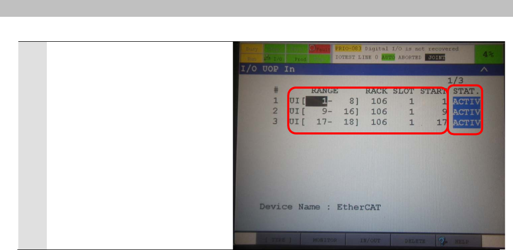
16
The I/O UOP In Screen is
displayed.
Confirm that the following settings
are made for RANGE, RACK,
SLOT, START.
RANGE: RACK: SLOT: START
・UI[1-8]:106:1:1
・UI[9-16]:106:1:9
・UI[17-18]:106:1:17
Confirm that STATUS is ACTIV.
*If the settings are different from the
above, try again from step 3 to
automatically assign UOP.
7
.
EtherCAT Connection Procedure
20
7.3. Setting Up the Controller
Set up the Controller.
7.3.1. Starting the Sysmac Studio and Installing the ESI File
Install the ESI file for the Robot Controller in the Sysmac Studio.
Install the Sysmac Studio and USB driver in the Personal computer beforehand.
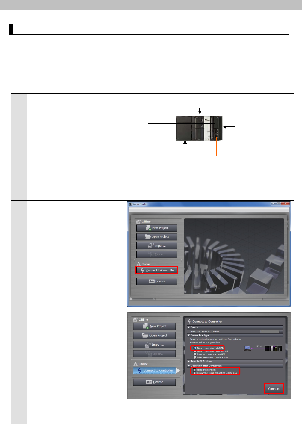
1
Connect the Ethernet cable to
the built-in EtherCAT port
(PORT2) of the Controller and
connect the USB cable to the
peripheral (USB) port.
As shown in 5.2. Device
Configuration, connect the
Personal computer, Robot
Controller, and Controller.
2
Turn ON the power supply to the
Controller.
3
Start the Sysmac Studio.
Click the Connect to Controller
Button.
* If a confirmation dialog for an
access right is displayed at
start, execute a selection to
start.
4
The Connect to Controller
Dialog Box is displayed.
Select the Direct connection via
USB Option for Connection
type.
Uncheck both the Upload the
project Check Box and the
Display the Troubleshooting
Dialog Box Check Box of
Operation after Connection.
Click the Connect Button.
USB cable
CPU Unit
End Cover
Power Supply Unit
Ethernet
cable
Controller
7
.
EtherCAT Connection Procedure
21
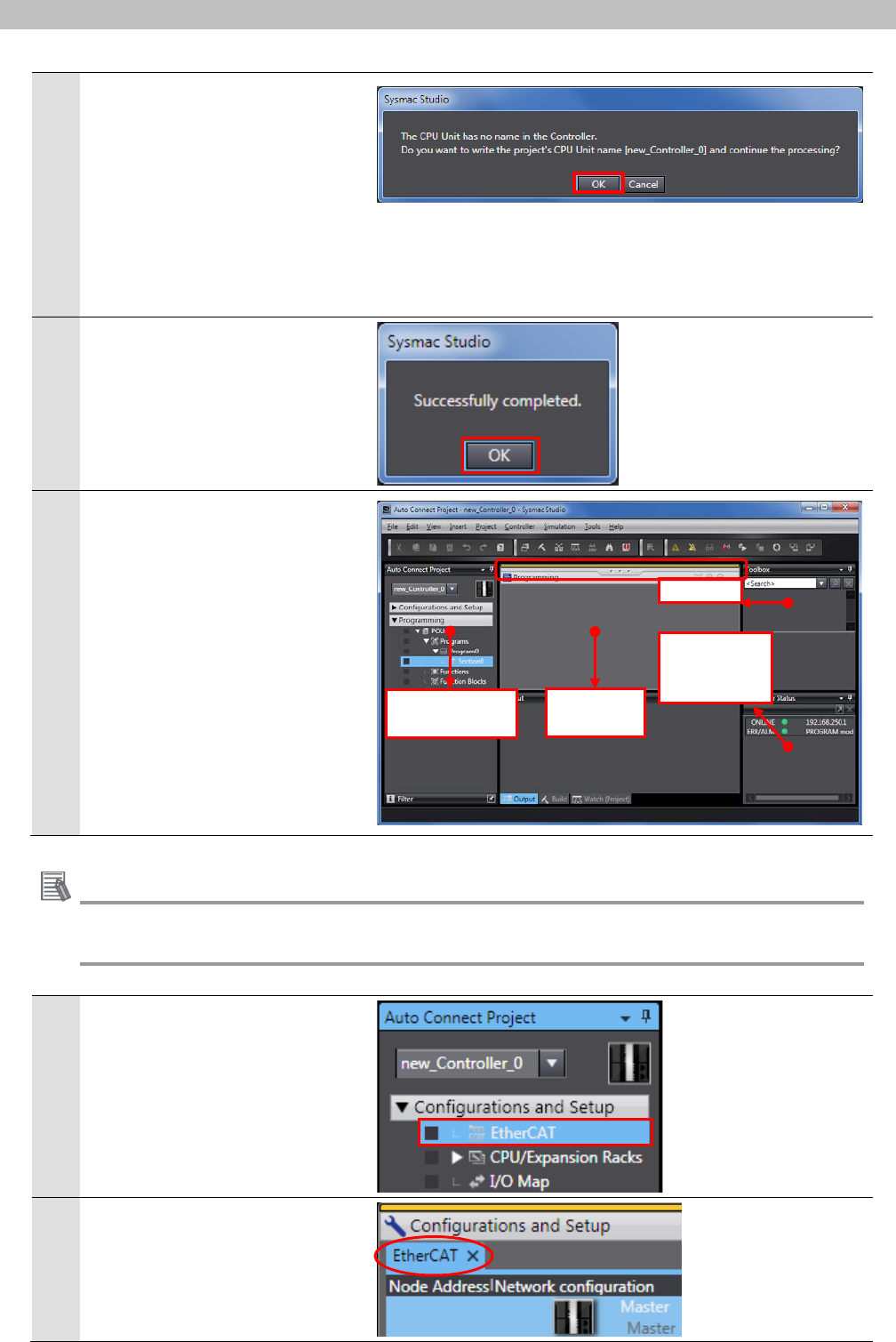
5
A confirmation dialog box on the
right is displayed. Check the
contents and click the OK
Button.
*The displayed dialog depends
on the status of the Controller
used. Check the contents and
click the OK or Yes Button to
proceed with the processing.
6
A dialog box on the right is
displayed. Check the contents
and click the OK Button.
7
The Auto Connect Project
Dialog Box is displayed online.
When an online connection is
established, a yellow bar is
displayed on the Pane.
The left pane is called Multiview
Explorer, the top right pane is
called Toolbox, the bottom right
pane is called Status Monitor
Pane, and the middle pane is
called Edit Pane.
Additional Information
For details on online connections to a Controller, refer to Section 6 Online Connections to a
Controller of the Sysmac Studio Version 1 Operation Manual (Cat. No. W504).
8
Double-click EtherCAT under
Configurations and Setup in
the Multiview Explorer.
9
The EtherCAT Tab Page is
displayed in the Edit Pane.
Status
Monitor Pane
Toolbox
Edit Pane
Multiview
Explorer

7
.
EtherCAT Connection Procedure
22
10
Right-click Master and select
Display ESI Library.
11
The ESI Library Dialog Box is
displayed. Click the this folder
link.
When the Explorer starts, close
the dialog box by clicking the
Close Button.
12
The Explorer starts and a folder
is opened, allowing you to install
the ESI file. Copy the prepared
fanuc_rs_esi0001.xml to this
folder.

7
.
EtherCAT Connection Procedure
23
13
Select Exit from the File Menu
to exit the Sysmac Studio.
A dialog box is displayed
confirming whether to save the
project. If you do not need to
save it, click the No Button.
*You need to restart the Sysmac
Studio after installing the ESI
file.
14
In the same way as steps 3 to
10, restart the Sysmac Studio
and display the ESI Library
Dialog Box.
Click the + Button of
fanuc_rs_esi0001 to confirm
that the FANUC R-30iB V8.20
Rev:0x00010000 device is
displayed.
Confirm that an exclamation
mark (warning) is not displayed.
Click the Close Button.
Precautions for Correct Use
If an exclamation mark (warning) is displayed for the ESI file, check the name of the ESI file
and obtain the ESI file with a correct name. If an exclamation mark (warning) is displayed
even when the name of the ESI file is correct, the file may be corrupted.
Contact the device manufacturer.
7
.
EtherCAT Connection Procedure
24
7.3.2. Setting Up the EtherCAT Network Configuration
Set up the EtherCAT network configuration.
Always confirm safety before you reset the Controller or any devices.
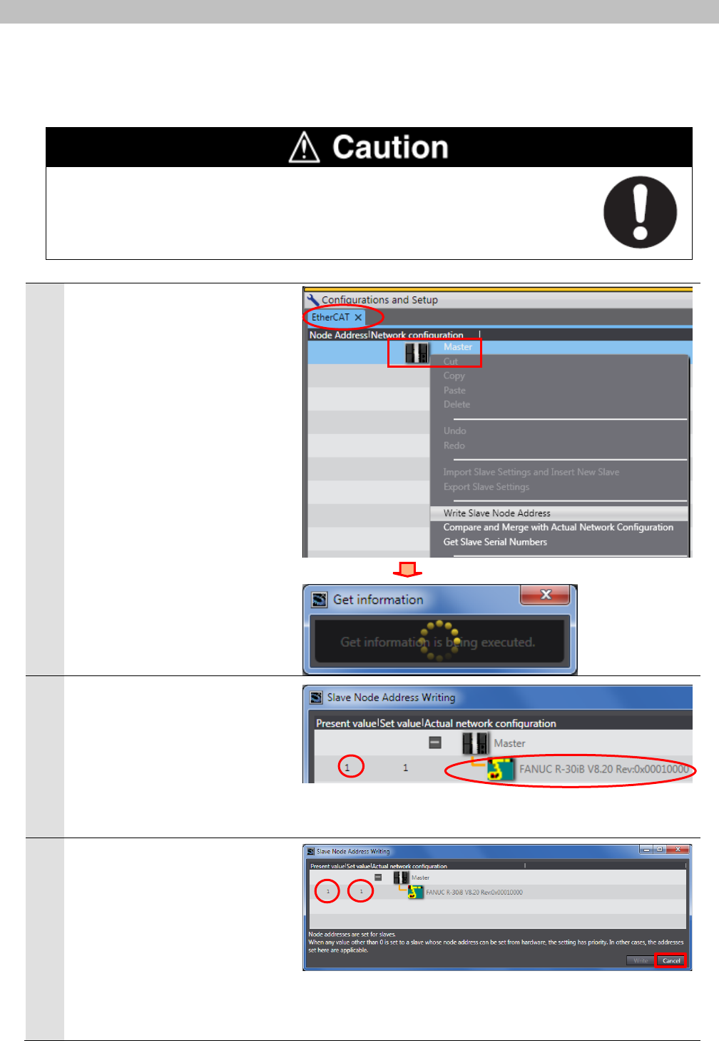
1
Right-click Master on the
EtherCAT Tab Page of the Edit
Pane, and select Write Slave
Node Address.
*
If the EtherCAT Tab Page is not
displayed on the Edit Pane,
display it by following step 8 of
7.3.1. Starting the Sysmac
Studio and Installing the ESI
File.
A screen is displayed stating
"Get information is being
executed".
2
The Slave Node Address Writing
Dialog Box is displayed.
The present value (setting node
address) and FANUC R-30iB
V8.20 Rev:0x00010000 are
displayed in the Actual network
configuration.
3
Confirm that the node address
of present value and set value is
1, respectively.
Click the Cancel Button.
*If the node address of present
value is not 1, set the value to
1. Click the Write Button.
When finished, cycle the power
supply to the Slave Unit.
7
.
EtherCAT Connection Procedure
25
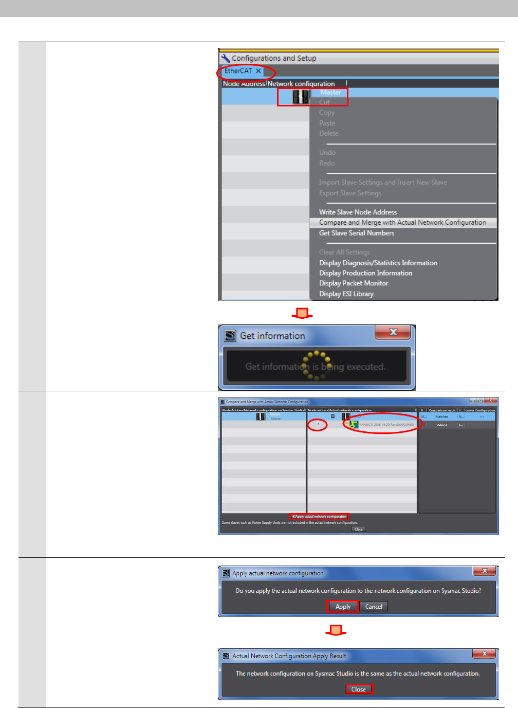
4
The EtherCAT Tab Page is
displayed again. Right-click
Master and select Compare
and Merge with Actual
Network Configuration.
A screen is displayed stating
"Get information is being
executed".
5
The Compare and Merge with
Actual Network Configuration
Dialog Box is displayed.
Node address 1 and FANUC
R-30iB V8.20 Rev:0x00010000
are added to the Actual network
configuration after the
comparison.
Click the Apply actual network
configuration Button.
6
A confirmation dialog box is
displayed. Check the contents
and click the Apply Button.
The dialog box on the right is
displayed. Click the Close
Button.
7
.
EtherCAT Connection Procedure
26
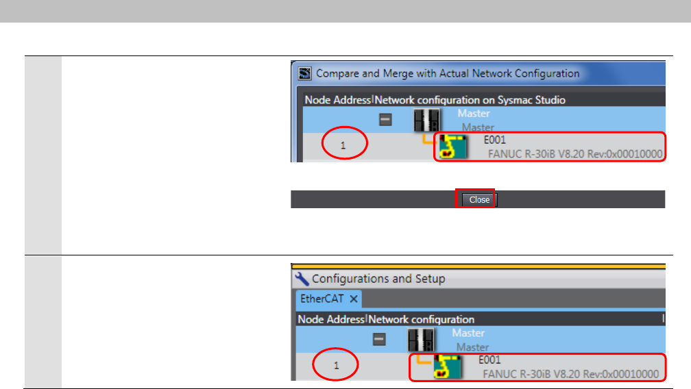
7
Node address 1, E001, and
FANUC R-30iB V8.20
Rev:0x00010000 are added to
the Network configuration on
Sysmac Studio.
Confirm that the data above are
added and click the Close
Button.
8
Node address 1, E001, and
FANUC R-30iB V8.20
Rev:0x00010000 are added to
the EtherCAT Tab Page on the
Edit Pane.
7
.
EtherCAT Connection Procedure
27
7.3.3. Setting the Device Variables
Set the device variables used for the EtherCAT Slave Unit.
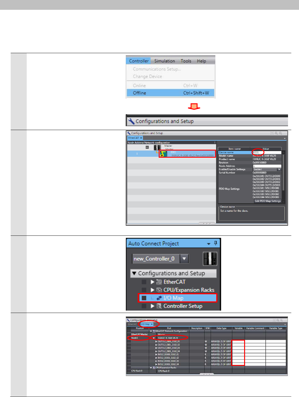
1
Select Offline from the
Controller Menu.
The yellow bar on the top of the
Edit Pane disappears.
2
Select FANUC R-30iB V8.20
Rev:0x00010000 set in the
previous step in the EtherCAT
Tab Page and confirm that
Device name is E001.
*Device name can be changed
as desired.
3
Double-click I/O Map under
Configurations and Setup in
the Multiview Explorer.
4
The I/O Map Tab Page is
displayed on the Edit Pane.
Confirm that Node1 is displayed
in the Position Column and the
Slave Unit is displayed.
*To manually set a variable
name for the Slave Unit, click a
column under the Variable
Column and enter a name.
7
.
EtherCAT Connection Procedure
28
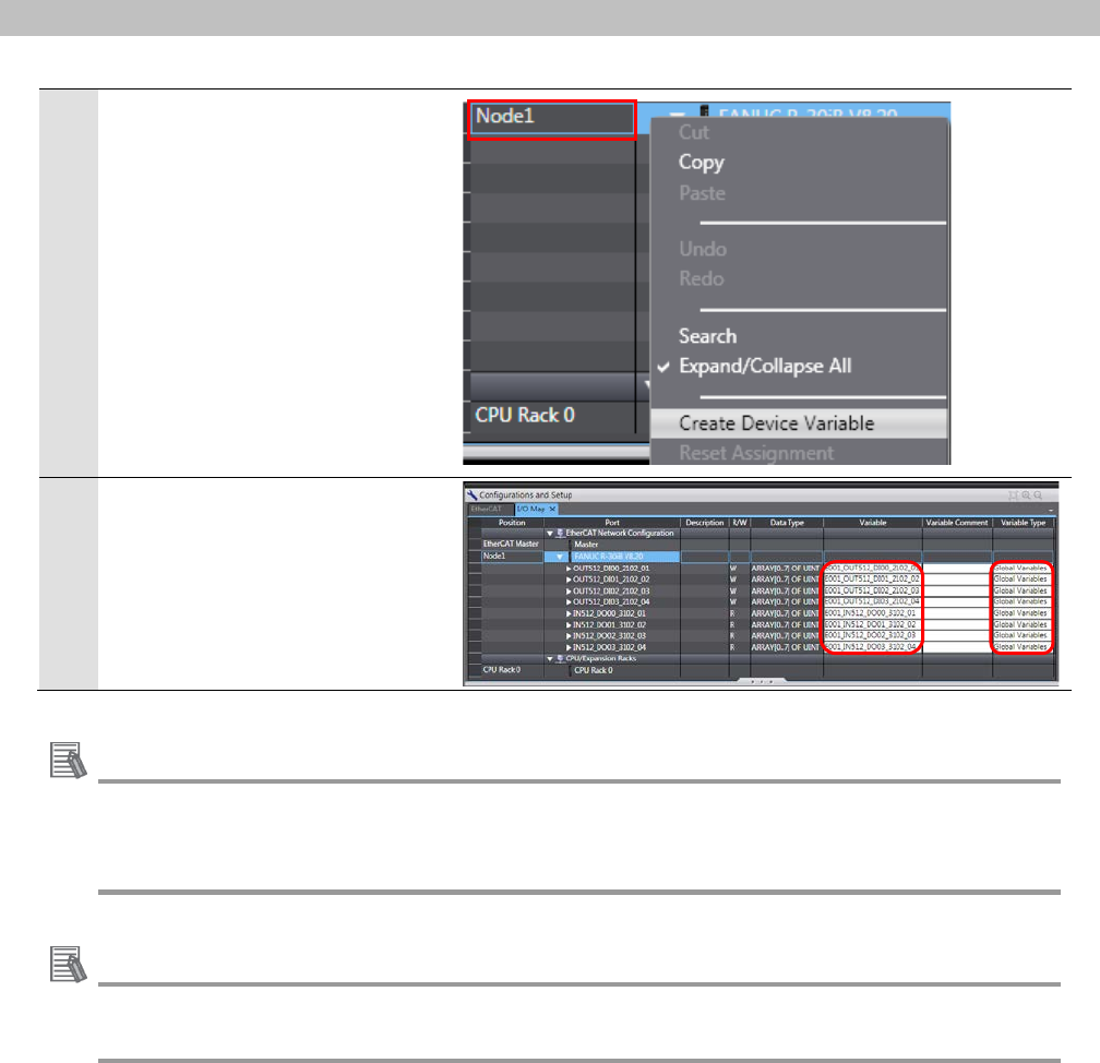
5
Right-click Node1 and select
Create Device Variable.
6
The variable names and
variable types are automatically
set.
Additional Information
The device variables are named automatically from a combination of the device names and
the port names. The default device names are “E" followed by a serial number that starts
from 001.
Additional Information
In this document, device variables are automatically named for a unit (a slave).
Device variables can also be automatically named for I/O ports.
7
.
EtherCAT Connection Procedure
29
7.3.4. Transferring the Project Data
Transfer the project data from the Sysmac Studio to the Controller.
Always confirm safety at the Destination Device before you transfer a user
program, configuration data, setup data, device variables, or values in memory
used for CJ-series Units from the Sysmac Studio.
The devices or machines may perform unexpected operation regardless of the
operating mode of the CPU Unit.
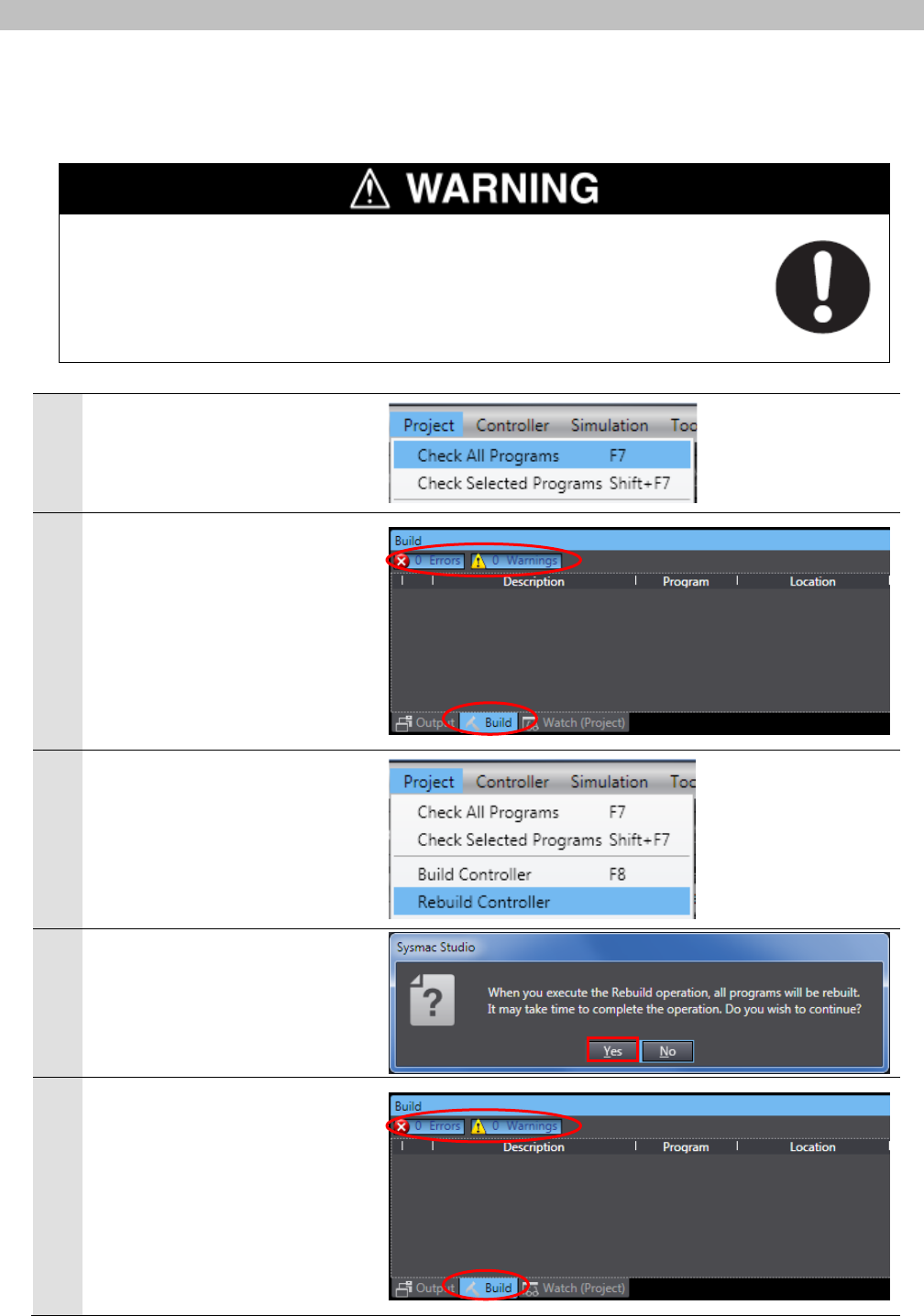
1
Select Check All Programs
from the Project Menu.
2
The Build Tab Page is displayed
on the Edit Pane.
Confirm that "0 Errors" and "0
Warnings" are displayed.
3
Select Rebuild Controller from
the Project Menu.
4
A confirmation dialog box on the
right is displayed. Confirm that
there is no problem and click the
Yes Button.
5
Confirm that "0 Errors" and "0
Warnings" are displayed in the
Build Tab Page.
7
.
EtherCAT Connection Procedure
30
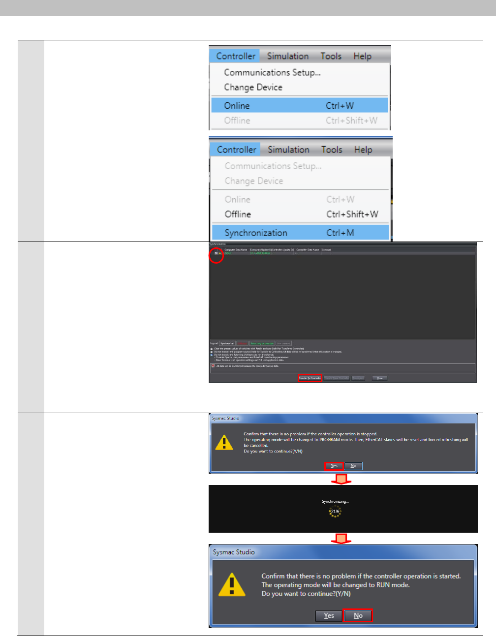
6
Select Online from the
Controller Menu.
7
Select Synchronization from
the Controller Menu.
8
The Synchronization Dialog Box
is displayed.
Confirm that the data to transfer
(NJ501 in the right dialog) is
selected. Then, click the
Transfer To Controller Button.
*After executing the Transfer To
Controller, the Sysmac Studio
data is transferred to the
Controller and the data is
compared.
9
A confirmation dialog box on the
right is displayed. Confirm that
there is no problem and click the
Yes Button.
A screen stating "Synchronizing"
is displayed.
A confirmation dialog box on the
right is displayed. Confirm that
there is no problem and click the
No Button.
*Do not return to RUN mode.
7
.
EtherCAT Connection Procedure
31
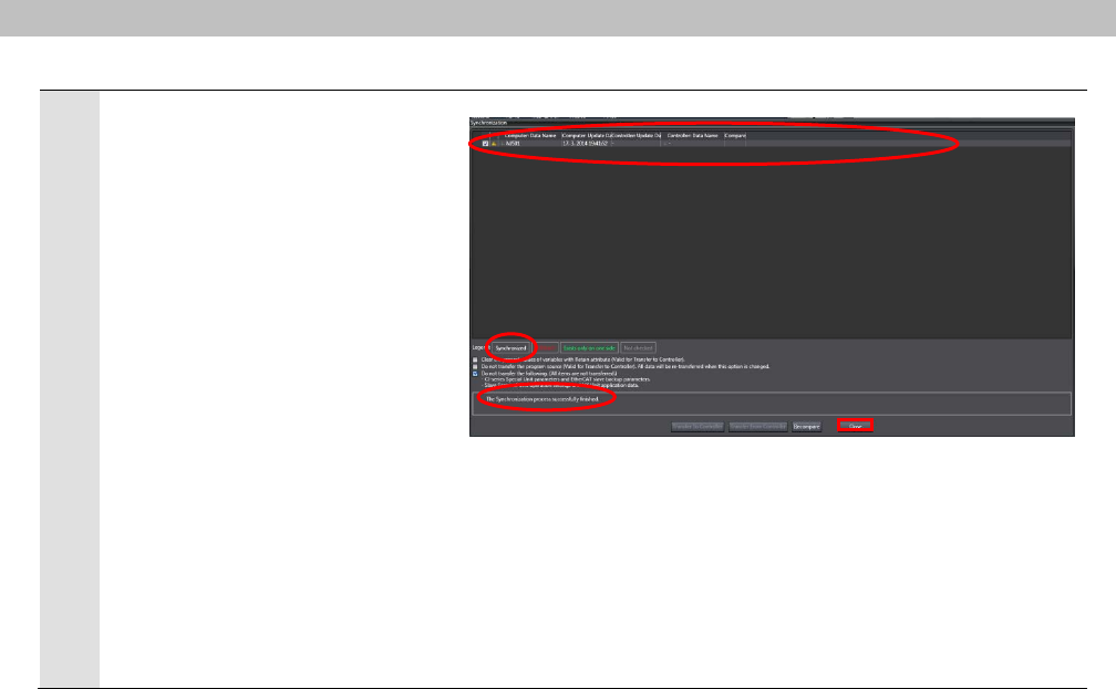
10
Confirm that the synchronized
data is displayed with the color
specified by "Synchronized",
and that a message is displayed
stating "The synchronization
process successfully finished".
If there is no problem, click the
Close Button.
*A message stating "The
synchronization process
successfully finished" is
displayed if the Sysmac Studio
project data and the data in the
Controller match each other.
*If the synchronization fails,
check the wiring and repeat
from step 1.

7
.
EtherCAT Connection Procedure
32
7.4. Checking the EtherCAT Communications
Confirm that the PDO Communications of EtherCAT are performed normally.
7.4.1. Checking the Connection Status
Check the connection status of the EtherCAT network.
1
Confirm that the EtherCAT
communications are performed
normally by checking the LED
indicators on the Controller.
The LED indicators in normal status
are as follows:
[NET RUN]: Lit green
[NET ERR]: Not lit
[LINK/ACT]: Flashing yellow
2
Select 0 --NEXT-- from the MENU 1
Menu of the Teach pendant on the
Robot Controller with the cursor key.
Press the ENTER key.
Select 4 STATUS from the MENU 2
Menu, and then select EtherCAT
with the cursor key.
Press the ENTER key.
*The software LED "Fault" indicated
by a red circle shows the following
status:
Lit red (ON): Alarm occurs.
Lit green (OFF): Alarm released.
* If the software LED "Fault" is lit red
(ON), resolve the cause of the
alarm and release them by
performing steps 4 to 8.
(FANUC Teach pendant)
(Alarm status)
Software LEDs
7
.
EtherCAT Connection Procedure
33
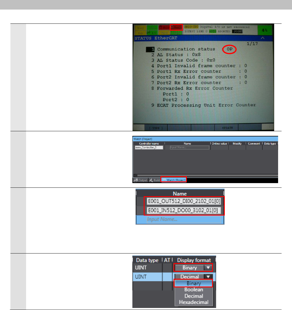
3
Confirm that the EtherCAT
communications are performed
normally on the Teach pendant.
The following are displayed.
Communication status: OP
Software LED "Fault": Lit red (ON)
*Software LED "Fault" can be lit red
under an error status other than an
EtherCAT error.
4
Take the following steps to release
the alarm caused by other than an
EtherCAT communications error on
the Robot Controller.
Select the Watch (Project) Tab
Page.
5
Enter the following names in the
Watch (Project) Tab Page for
monitoring. Click an Input Name…
in the Name Column to enter a new
name.
E001_OUT512_DI00_2102_01[0]
E001_IN512_DO00_3102_01[0]
6
Select Binary from the pull-down
list of Display format of the variable
you set.
7
.
EtherCAT Connection Procedure
34
7
Enter 0000 0000 1000 0111 in the
Modify Column of
E001_OUT512_DI00_2102_01[0].
The Online value of
E001_OUT512_DI00_2102_01[0]
changes to 0000 0000 1000 0111.
*As shown on the right figure, turn
ON UI[1](*IMSTP:immediate stop),
UI[2](*Hold: temporary stop),
UI[3](*SFSPD: safety speed), and
UI[8](Enable: ENBL).
Do not turn ON UI[6](Start:
external start), UI[7](Home:
Homing),and UI[18](Prod Start:
automatic operation start).
8
Press the Alarm release Button on
the front panel of the Robot
Controller.
7
.
EtherCAT Connection Procedure
35
7.4.2. Checking the Data that are Sent and Received
Confirm that the correct data are sent and received.
Always confirm safety at the Destination Device before you transfer a user
program, configuration data, setup data, device variables, or values in memory
used for CJ-series Units from the Sysmac Studio.
The devices or machines may perform unexpected operation regardless of the
operating mode of the CPU Unit.
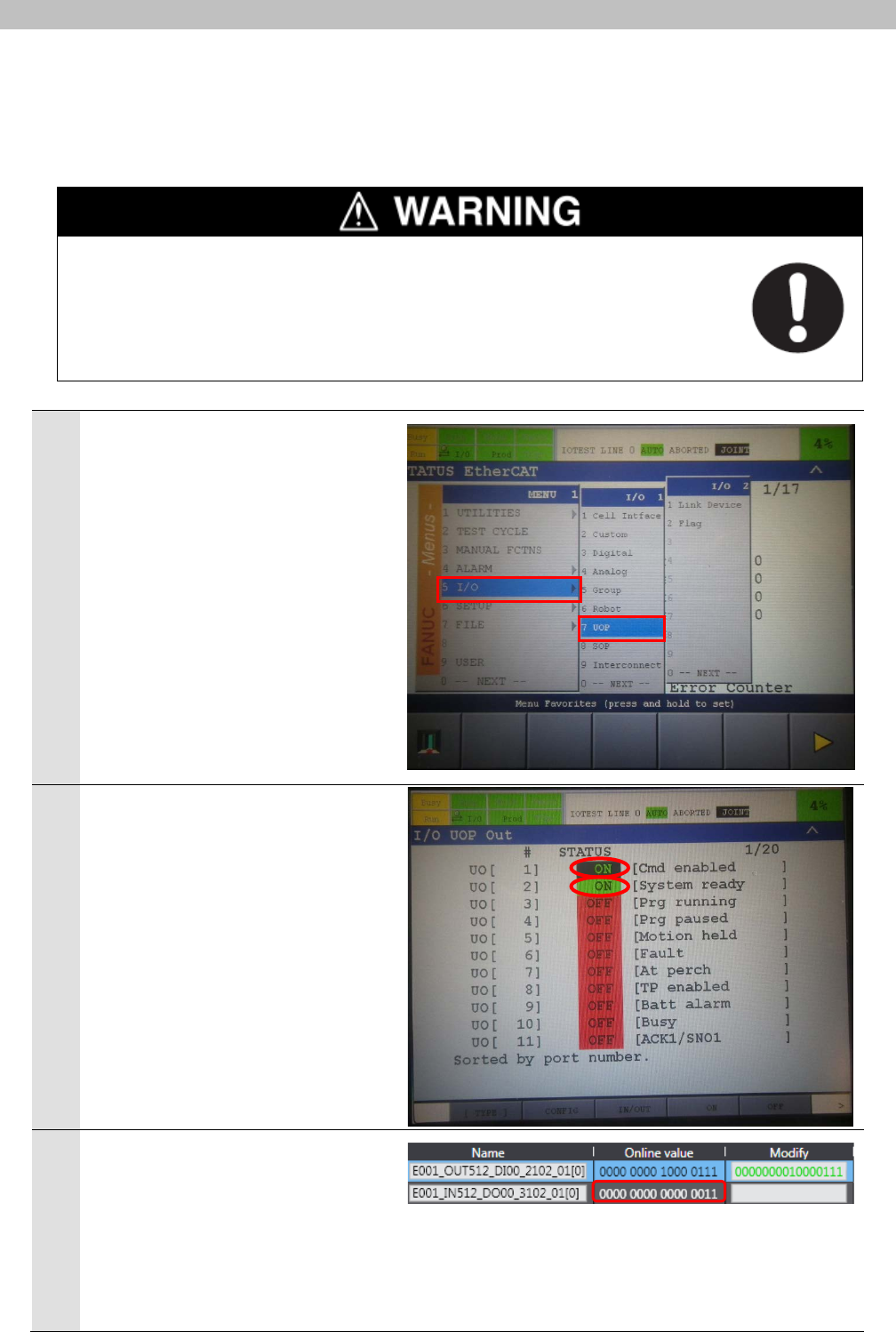
1
Press the MENU key on the Teach
pendant.
Select 5 I/O - 7 UOP from the
MENU 1 Menu with the cursor key.
Press the ENTER key.
2
The I/O UOP Out Screen is
displayed.
On the right figure, UO[1] and UO[2]
are turned ON that shows the status
of the Robot Controller.
3
The Online value of
E001_IN512_DO00_3102_01[0]
changes to 0000 0000 0000 0011.
*For information on how to set the
Watch Tab Page, refer to steps 5 to
8 of 7.4.1. Checking the
Connection Status.
7
.
EtherCAT Connection Procedure
36
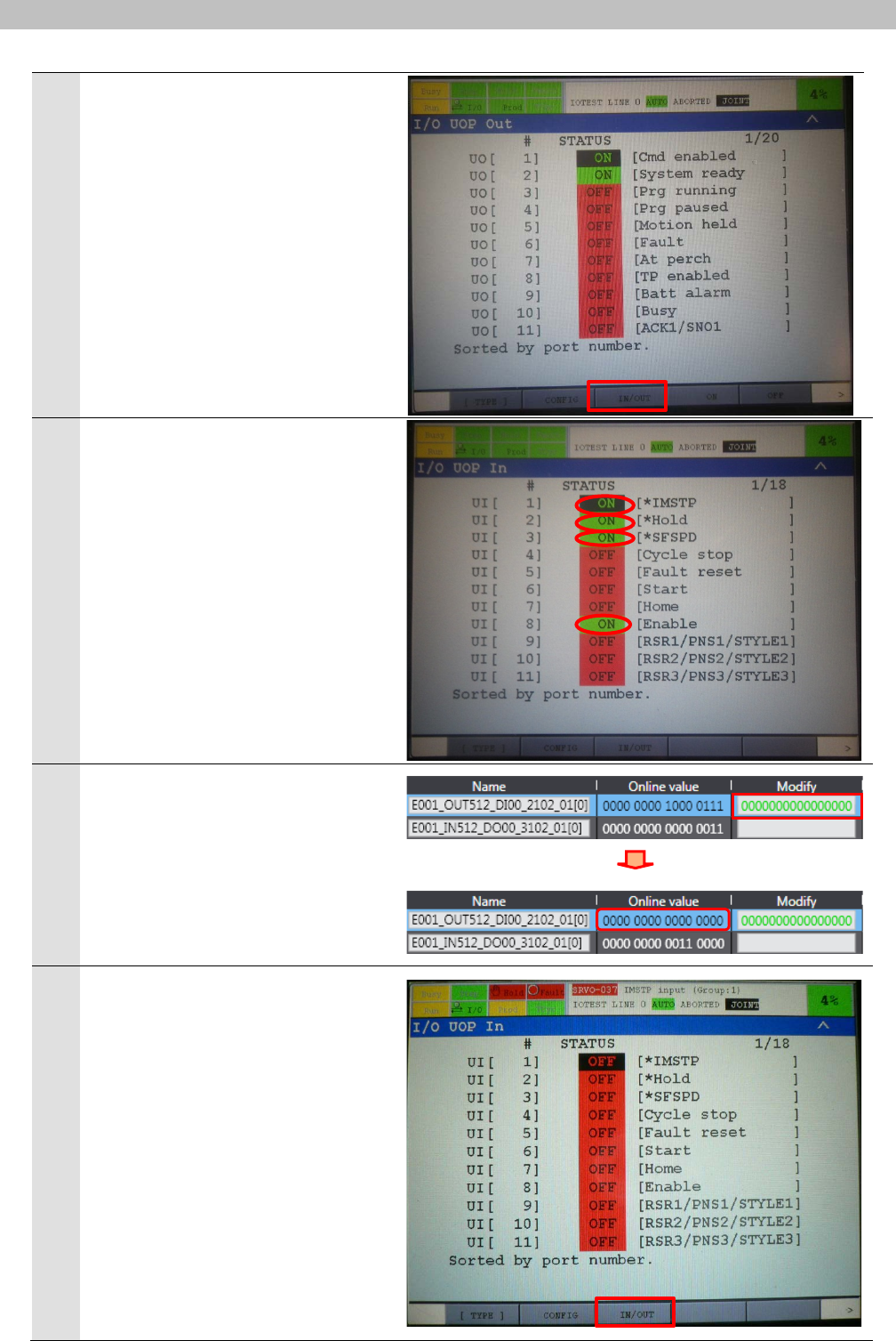
4
Press the F3 key (IN/OUT).
5
The I/O UOP In Screen is displayed.
On the right figure, UI[1], UI[2],
UI[3], UI[8] of the Robot Controller
are turned ON.
6
Enter 0000 0000 0000 0000 in the
Modify Column of
E001_OUT512_DI00_2102_01[0].
The Online value of
E001_OUT512_DI00_2102_01[0]
changes to 0000 0000 0000 0000.
7
The I/O UOP In Screen is displayed.
Press the F3 key (IN/OUT).
7
.
EtherCAT Connection Procedure
37
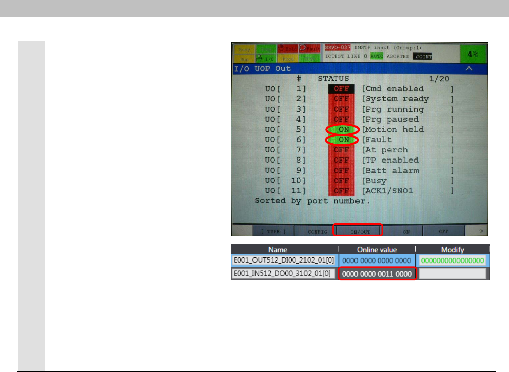
8
The I/O UOP Out Screen is
displayed.
On the right figure, UO[5] and UO[6]
are turned ON that shows the status
of the Robot Controller.
9
The Online value of
E001_IN512_DO00_3102_01[0]
changes to 0000 0000 0011 0000.
*For information on how to release
the software LED "Fault" by turning
ON UO[1](Cmd Enabled) and
UO[2](System Ready), refer to
steps 4 to 8 of 7.4.1. Checking the
Connection Status.
8
.
Initialization Method
38
8. Initialization Method
This document explains the setting procedure from the factory default setting.
Some settings may not be applicable as described in this document unless you use the
devices with the factory default setting.
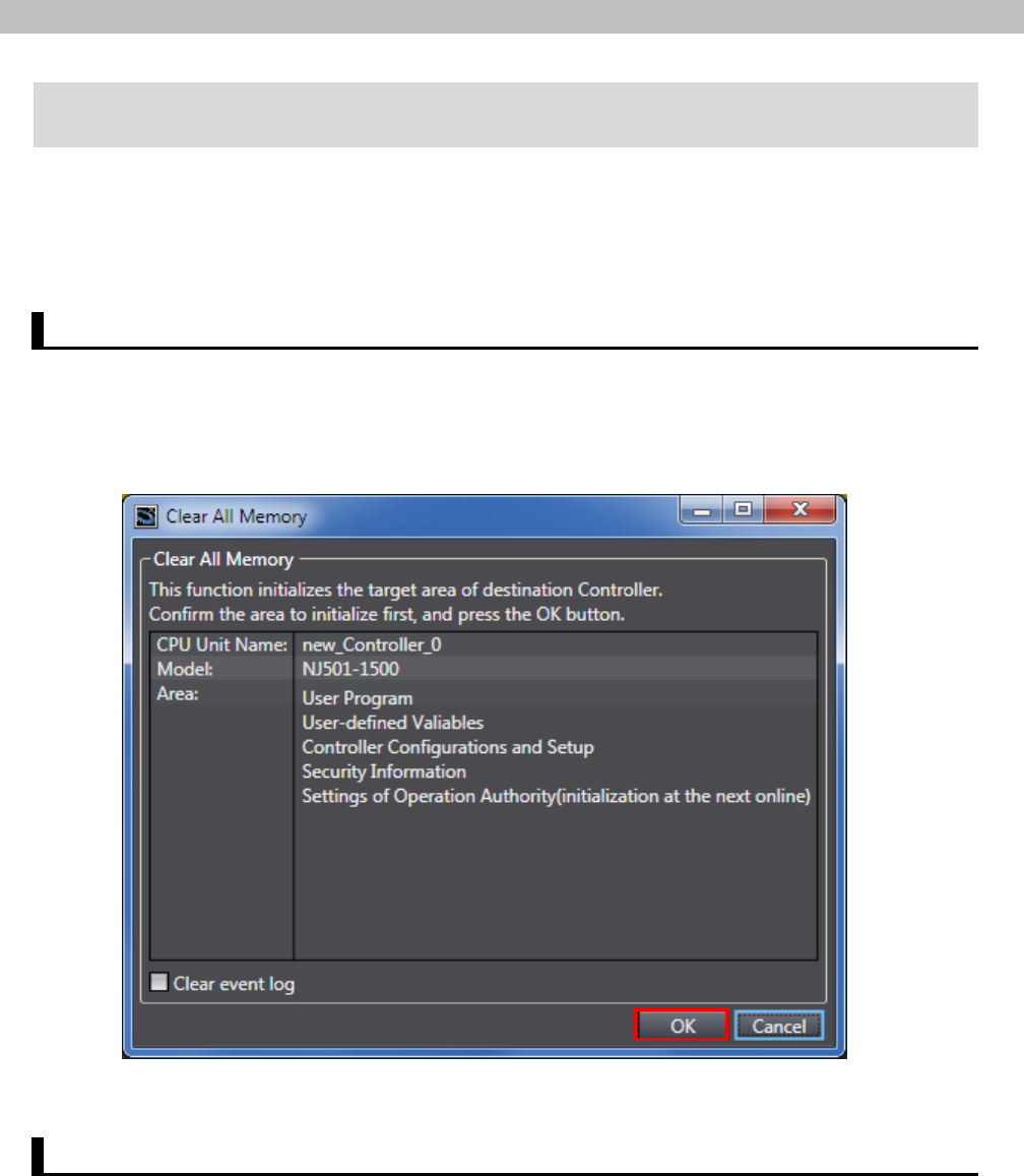
8.1. Initializing the Controller
To initialize the settings of the Controller, select Clear All Memory from the Controller Menu of
the Sysmac Studio. The Clear All Memory Dialog Box is displayed. Check the contents and
click the OK Button.
8.2. Initializing the FANUC Robot Controller
The Robot Controller is initialized by restoring a backup of factory default parameters.
For details on how to backup and restore parameters of the Robot Controller, refer to the
FANUC Robot series R-30iB/R-30iB Mate CONTROLLER EtherCAT Interface OPERATOR’S
MANUAL(Cat.No.B-83704EN).
9
.
Revision History
39
9. Revision History
Revision
code
Date of revision Revision reason and revision page
01 Aug. 18, 2014 First edition
40

2014
0814(-)
P605-E1-01
