1272 99 06 1500 6inch Lift Kit Rsc_1272 Rsc
User Manual: Pdf rsc_1272
Open the PDF directly: View PDF ![]() .
.
Page Count: 12
92127200
99-06 CHEVY/GM 1500 6” LIFT KIT
Thank you for choosing Rough Country for all of your suspension needs.
Rough Country recommends a certified technician installs this system. In addition to these instructions, professional
knowledge of disassemble/reassembly procedures as well as post installation checks must be known. Attempts to install
this system without this knowledge and expertise may jeopardize the integrity and/or operating safety of the vehicle.
Please read all the instructions before beginning the installation. Check the kit hardware against the Kit Contents list on
next page. Be sure you have all the needed parts and understand where they go. Also please review the tools needed
list to be certain that you have the tools necessary to complete the installation.
PRODUCT USE INFORMATION
As a general rule, the taller a vehicle is the easier it will roll. We strongly recommend, because of rollover possibility, that
seat belts and shoulder harnesses should be worn at all times. Avoid situations where a side rollover may occur. Braking
performance and capabilities are decreased when significantly larger/heavier tires and wheels are used. Take this into
consideration while driving. Also, speedometer recalibration is necessary when larger tires are installed.
Do no add, alter, or fabricate any factory or after-market parts which increase vehicle height over the intended height of
the Rough Country product purchased. Mixing component brands, lifts, with this suspension lifts voids all warranties.
Rough Country makes no claims regarding lifting devices and excludes any and all implied claims. We will not be re-
sponsible for any product that is altered.
Due to differences in manufacturing, dimension and inflated measurements, tire and wheel combinations should be test
fit prior to installation. For this application we recommend a wheel not to exceed 9” in width with 4.5 “ of backspacing..
Additionally a quality tire of radial design is recommended, not exceeding 35” tall and 12.5” wide. If this vehicle was
equipped from the factory with 17” wheels and if purchasing new wheels, the wheel size must not be below 17” but can
be larger than 17” due to the vehicle being equipped with larger calipers /rotor.
NOTICE TO DEALER AND VEHICLE OWNER
Any vehicle equipped with any Rough country product must have the “Warning to Driver” decal installed on the sun visor
or dash. The decal is to act as a constant reminder for whoever is operating the vehicle of its unique handling character-
istics. INSTALLING DEALER—It is your responsibility to install the warning decal and to forward these installation in-
structions on too the vehicle owner for review and to be kept in the vehicle for its service life.
We hope installing your Rough Country lift kit is a positive experience. Please note that variations in construc-
tion and assembly in the vehicle manufacturing process will virtually ensure that some parts may seem difficult
to install. Additionally, the current trend in manufacturing of vehicles results in a frame that is highly flexible
and may shift slightly on disassembly prior to installation. The use of pry bars and tapered punches for align-
ment is considered normal and usually does not indicate a faulty product. However, if you are uncertain about
some aspect of the installation process, please feel free to call our tech support department at 800-222-7023. We
do not recommend that you modify the Rough Country parts in any way as this will void any warranty ex-
pressed or implied.
Thank you for choosing Rough Country for all of your suspension needs.
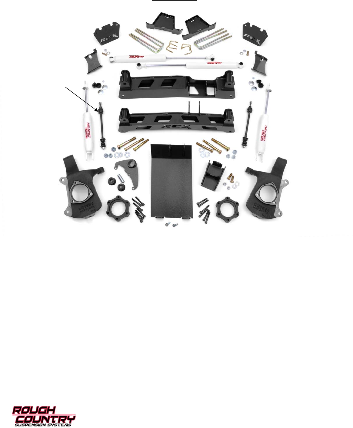
KIT CONTENTS
Rear Cross Member
Front Shocks (2)
Pass Diff Brkt
CV Spacer (2)
Dr. Diff Brkt Driver Side
Knuckle
Skid Plate
Sway Bar
Link (2)
Front Cross Member
Pass Side
Knuckle
Rear U-bolts (4) Rear Blocks (2)
Rear Shocks (2)
Kit Contents:
1272 Box1
Rear Cross Member
Dr Torsion Drop Bracket
Pass Torsion Drop Bracket
Dr Bump Stop Bracket
Pass Bump Stop Bracket
1272 Box2
Frt Skid Plate
Frt Cross Member
Dr Diff Bracket
Pass Diff Bracket
1272 Box3
Front Shock Part #658441 (2)
Rr Shock Part # 658556 (2)
CV Shaft Spacers (2)
Lift Blocks (2)
9/16” X 2 1/2” X 12 1/2” U-bolts (4)
Front Sway Bar Links (2)
1285
Driver Side Knuckle
Pass Side Knuckle
Fastener Breakdown:
For Driver Side Dif Drop Brkt.
Poly Bushings (2)
2.41” x 9/16”ID Sleeve (1)
For Bump Stop Bracket
1/2” x 1 1/2” Bolt (2)
1/2” Washer (2)
1/2” Nut (2)
For Rear Cross Member
5/8” x 5 1/2” Bolt (2)
5/8” Washer (4)
5/8” Nut (2)
For Pass Side Dif Drop Brkt
1/2” x 1 1/2” Bolt (2)
1/2” Washer (4)
1/2” Nut (2)
For Front Cross Member
5/8” x 4 1/2” Bolt (2)
5/8” Washer (4)
5/8” Nut (2)
For Skid Plate
3/8” x 1” Self Taping Bolt (2)
1/2” x 4 1/2” bolt (1)
1/2” Washer (2)
1/2” Nut (1)
For Axle CV Spacers
10mm x 65mm Allen Bolt (12)
For Torsion Bar Drop Brackets
1/2” x 1 1/2” Bolts (8)
1/2” Lock Nuts (8)
Bushings (4)
Sleeves (2)
For Front Shock Absorbers
Stem Bushings Female(2)
Stem Bushings Male (2)
Stem Washer (4)
3/8” Nut (2)
For Rear U-Bolts
9/16” Washer (8)
9/16” Nut (8)
7/16” Washer (8)
7/16” Nut (8)
For Rear Shock Absorbers
Hourglass Bushing (4)
Shock Sleeve (4)
Dr Bump Stop Bracket Pass Bump Stop Bracket
Torsion Bar Bracket (2)
TORQUE SPECS:
Size Grade 5 Grade 8
5/16” 15 ft/lbs 20 ft/lbs
3/8” 30 ft/lbs 35 ft/lbs
7/16” 45 ft/lbs 60 ft/lbs
1/2” 65 ft/lbs 90 ft/lbs
9/16” 95 ft/lbs 130 ft/lbs
5/8” 135 ft/lbs 175 ft/lbs
Class 8.8 Class 10.9
6MM 5 ft/lbs 9 ft/lbs
8MM 18ft/lbs 23 ft/lbs
10MM 32ft/lbs 45ft/lbs
12MM 55ft/lbs 75ft/lbs
14MM 85ft/lbs 120ft/lbs
16MM 130ft/lbs 165ft/lbs
18MM 170ft/lbs 240ft/lbs
Floor Jack
Jack Stands
10mm socket /wrench
11mm socket /wrench
13mm Deep Socket
13mm wrench
15mm socket / wrench
17mm socket / wrench
18mm socket /wrench
19mm socket /wrench
21mm socket /wrench
24mm socket /wrench
35mm socket
9/16 socket /wrench
7/8” deep well socket
Torsion bar Tool
Drill
17/32 Drill Bit
Loc-Tite
Reciprocating Saw
TOOLS NEEDED:
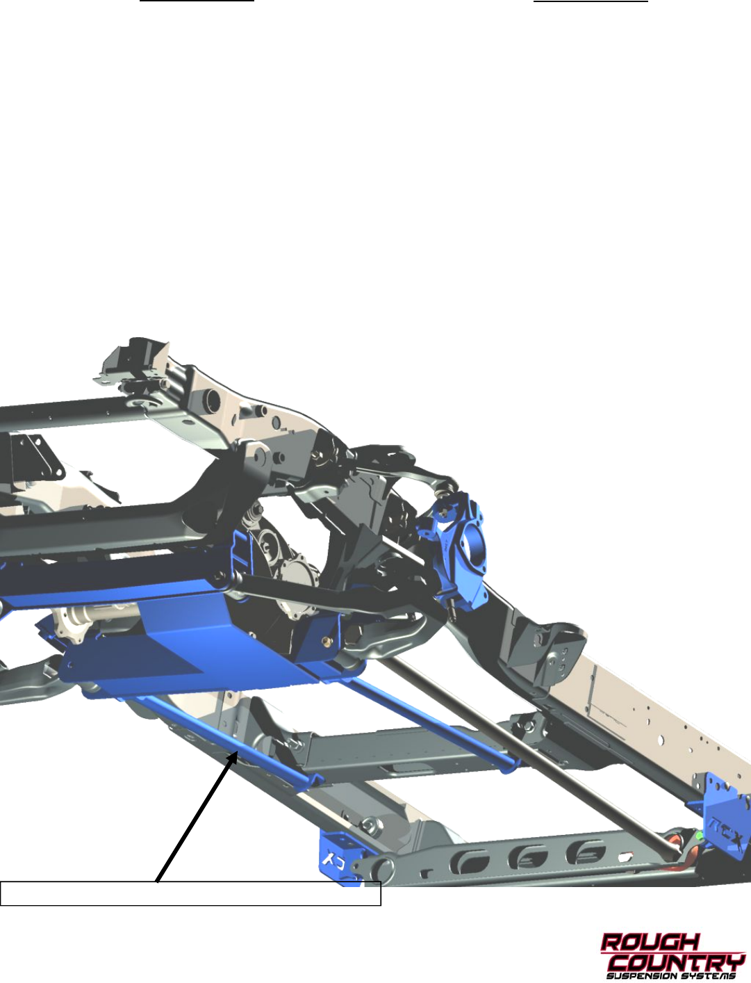
CAD DRAWING SHOWING KIT COMPONENTS AND INSTALLED LOCATIONS
DRAWING SHOWN WITH OPTIONAL KICKER BRACES
DRAWING SHOWN WITH OPTIONAL KICKER BRACES
FRONT INSTALLATION
1. Place the truck on a clean level surface and set the parking brake. Chock the rear wheels. Using a floor jack raise
the front of the truck and support the frame rails with jack stands. Never work under an unsupported vehicle. Using a
7/8” deep well socket remove the front wheels.
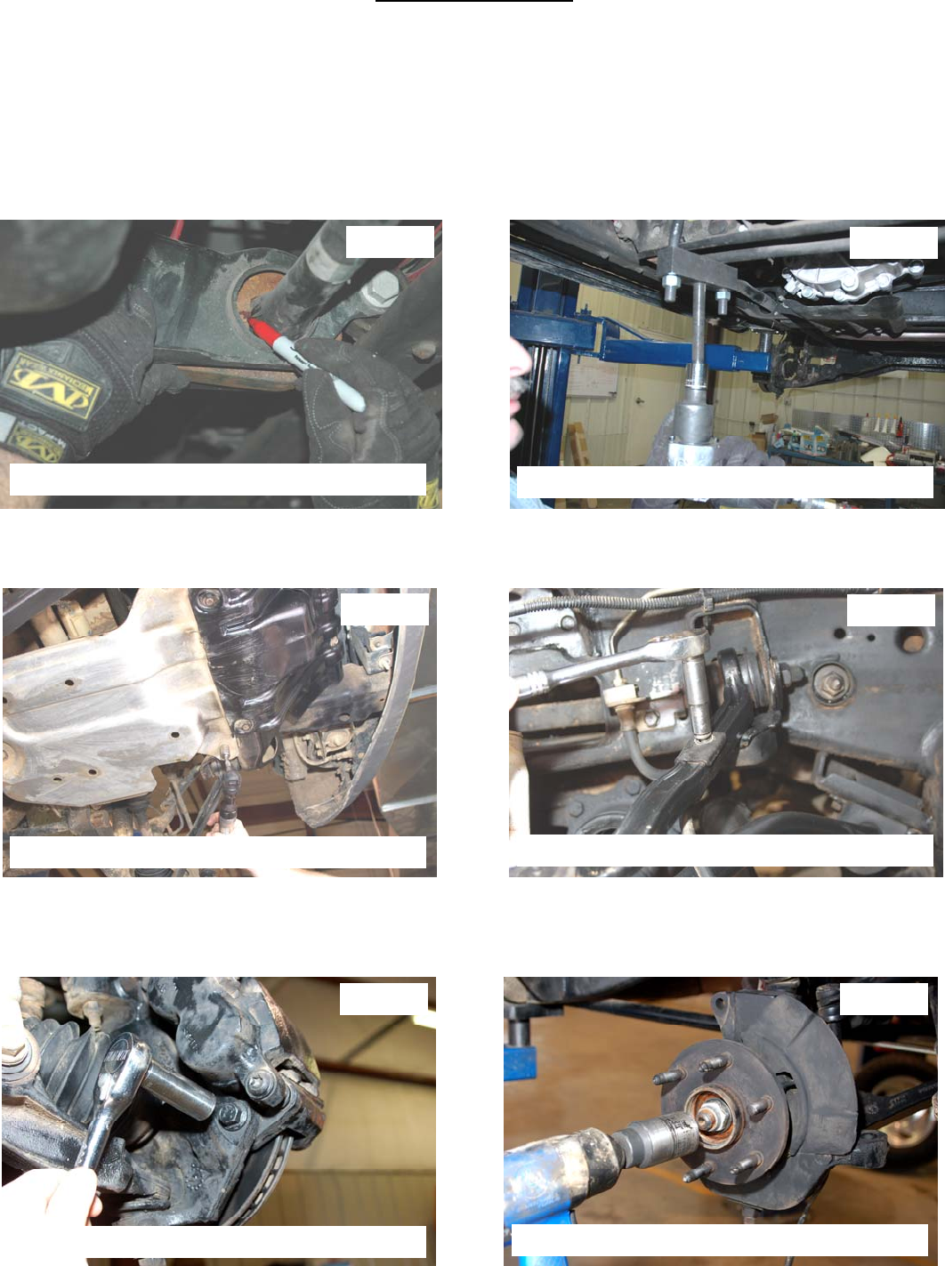
2. Locate the torsion bar adjuster bolt on the bottom of the rear cross member, measure the threads showing on the
torsion bar adjuster bolt. Mark the position of the torsion bars on the control arm and torsion bar key. Mark both the
drivers side and passenger side. See Photo 1.
3. Using a torsion bar tool, relieve the pressure from the torsion bar adjuster bolt and remove the bolt and threaded
block. See Photo 2.Warning: Be extremely careful when loading and unloading the torsion bars; there is a tremen-
dous amount of stored energy in the bars. Keep you hands and body clear of the adjuster arm assembly and the
puller tool in case anything slips or breaks.
4. Using a 15 mm socket remove the factory lower skid plate. See Photo 3.
5. Starting on the drivers side use a 10mm socket to remove the brake line from the upper control arm and knuckle.
Unplug the ABS wire from the frame rail. See Photo 4.
6. Using a 18mm socket unbolt the brake caliper and rotor. Secure the brake caliper out of harms way. See Photo 5.
7. Using a 35 mm socket remove the CV nut from the knuckle. See Photo 6. Remove the tie rod from the stock
knuckle using a 18mm wrench. Strike the side of the knuckle where the tie rod mounts to dislodge the tapered tie rod
end. Retain the stock hardware for reuse.
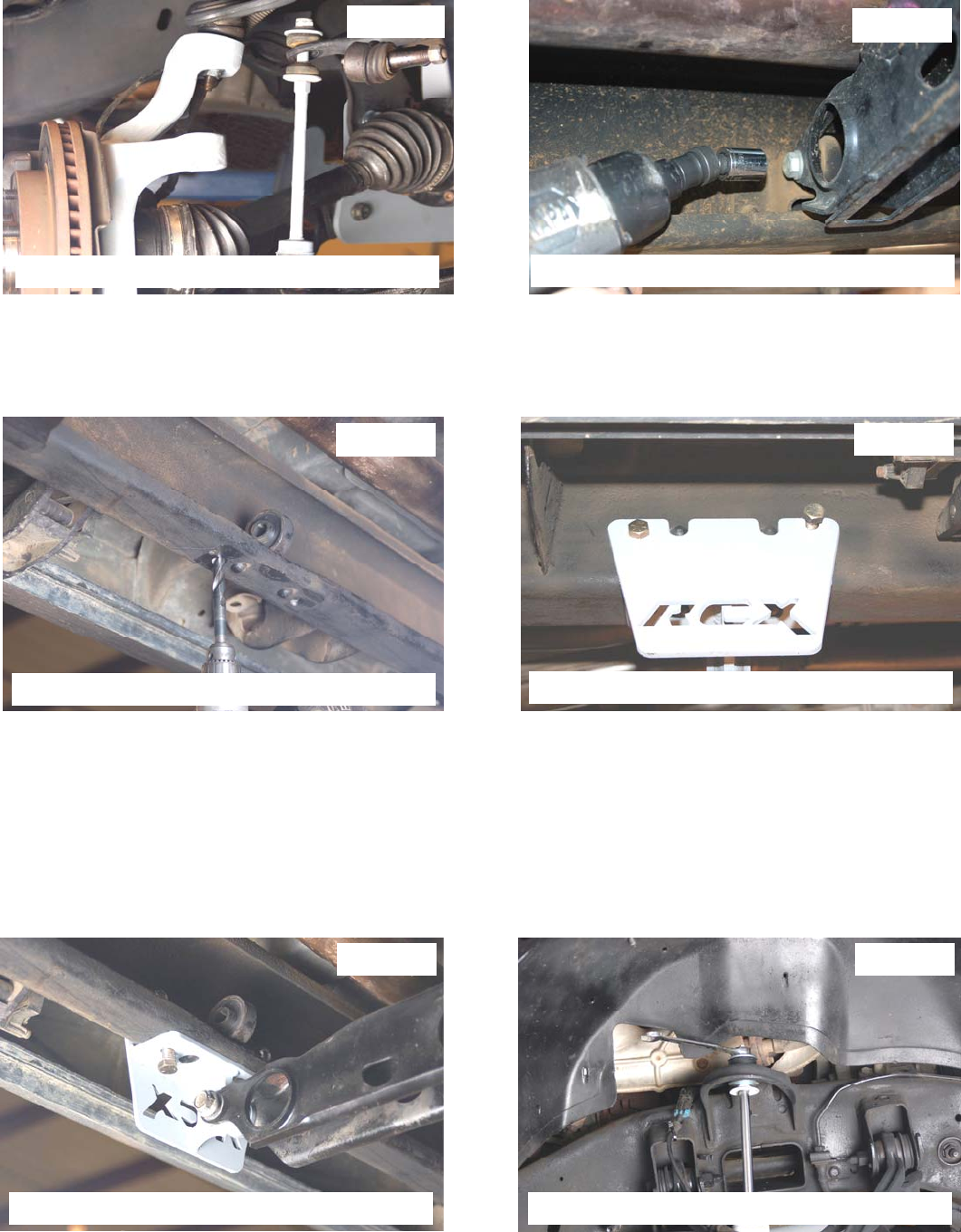
Photo 1 Photo 2
Photo 3 Photo 4
Photo 5 Photo 6
Mark torsion bar and torsion bar keys Remove torsion bar keys
Remove the skid plate Remove the brake line from the upper arm
Remove the brake caliper bracket Remove the spindle nut
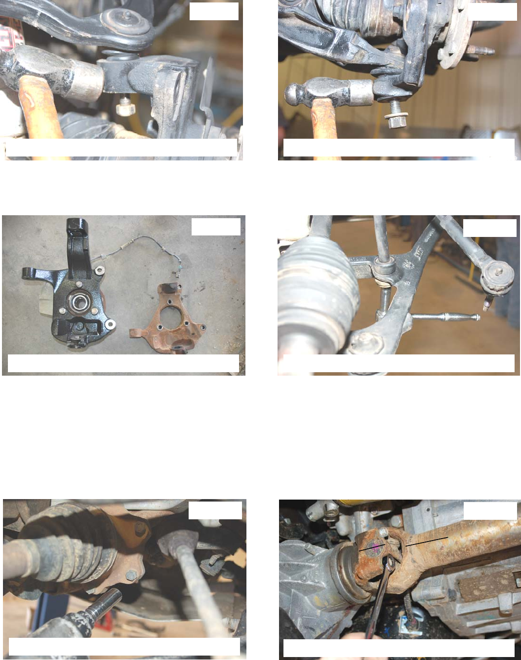
8. Using a 18mm wrench for the upper ball joint and a 24 mm deep well socket for the lower, remove the ball joint nuts.
Using a hammer hit the knuckle as shown until the ball joint is free. See Photo 7 & 8. Remove the knuckle.
9. Remove the three factory bolts that hold the wheel bearing to the stock knuckle. Remove the wheel bearing and
dust cover using a 15mm socket. Locate the new knuckles supplied with the kit and using Loc-Tite; install the bear-
ing with the factory hardware on the new knuckle. Tighten to 133 ft.lbs. See Photo 9.
10. Using a 13mm deep well socket remove the sway bar link from the lower control arm and sway bar. See Photo 10.
11. Using a 15 mm wrench remove the upper shock nut. Using a 21 mm socket and 21 mm wrench remove the lower
shock bolt. Remove the shock. Retain the hardware for reuse.
12. Using a 15mm socket remove the 6 inner CV bolts. See Photo 11. Set CV half shaft aside for reuse.
13. Using a 18mm wrench and a 24 mm socket remove the lower control arm hardware and remove the lower control
arm. Retain the hardware for reuse. Repeat steps 5 through 13 on passenger side.
14. Support the differential with a floor jack and remove the two nuts on the passenger side that secures the differential
to the frame using a 21mm wrench. Remove the upper differential bolt that secures the driver side differential to the
frame using a 21mm wrench.
15. Mark the front driveshaft and yoke for reference and remove the front driveshaft from the differential using a 11mm
wrench. Secure driveshaft out of harms way. See Photo 12.
Photo 7 Photo 8
Photo 9 Photo 10
Photo 11 Photo 12
Remove the skid plate Remove the knuckle from the lower ball joint
Install the bearing in the new knuckle Remove the sway bar link from the lower arm
Remove the shaft from the differential Remove the drive shaft from the differential
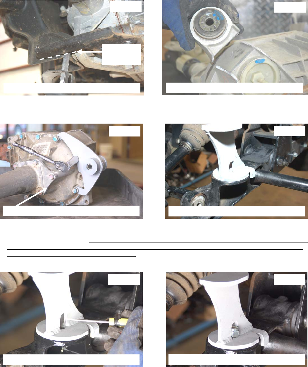
16. Remove the lower differential bolt on the drivers side using a 21mm wrench. Jack up the differential to allow for the
trimming of the drivers side stock mount.
17. Cut the frame as shown in Photo 13 with a reciprocating saw. After trimming, Remove the differential vent hose,
differential plug and the plug clips from the axle. With assistance lower the differential down and remove from the
vehicle.
18. Cut the differential as shown in Photo 14 using a reciprocating saw. Take care not to damage the differential.
19. Locate the driver differential bracket and install the bushings /sleeve in the mount. Install on the differential as shown
with factory hardware using a 15mm socket. Tighten to 35ft. Lbs. See Photo 15.
20. Install the bump stop bracket on the lower control arm. Note: There is a driver and passenger side bracket.
21. Install the bump-stop bracket on the lower control arm. Note: There is a driver and passenger side bracket
22. Using the bump-top as a guide, mark the lower control arm as shown and remove the bracket from the arm. See
Photo 17. Driver Side shown. A template is included it is recommended to use the template to check that the
hole is centered in the mount. Failure to confirm the proper location of the hole may lead to interference of
the shock absorber by the bump-stop bracket.
23. Drill the lower control arms using a 17/32” drill bit and reinstall the bump-stop bracket on the lower control arm and
tighten the supplied 1/2” x 1 1/2” bolts, washers & nuts using a 3/4” wrench See Photo 18.
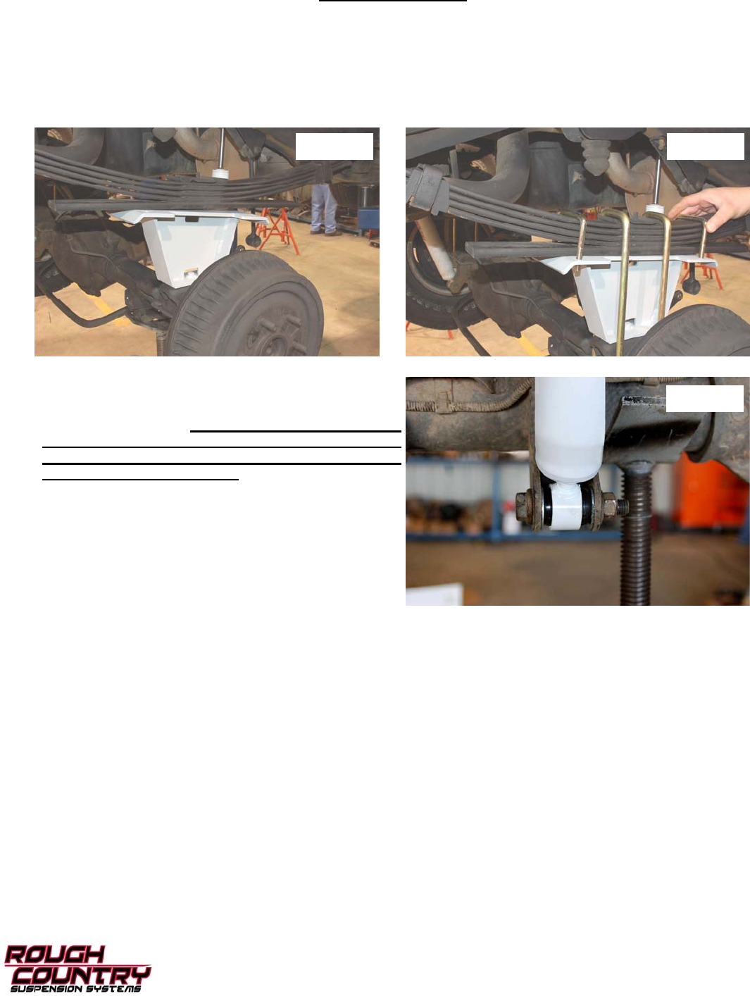
Photo 15
Photo 14
Photo 13
Cut Along Line
Removing
Completely
Photo 17 Photo 18
Photo 16
Cut stock rear diff bracket Cut differential mount
Install the new diff mount Install the bump stop bracket ( Dr Shown)
Mark the hole to be drilled Install the supplied hardware
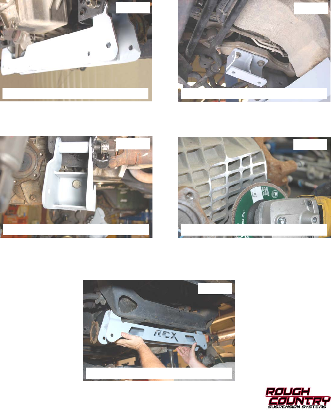
24. Install the rear cross-member as shown in Photo 19 with supplied 5/8” X 5 1/2” bolts, washers and nuts. Install the
bolts from the front to the back. Do not tighten at this time. If the optional kicker braces were purchased with this kit,
install the mouting brackets on the rear cross member using the instructions included with that kit.
25. Install the passenger side differential bracket as shown in Photo 20 (tall end of taper positioned towards front of ve-
hicle) with the factory hardware using a 21mm wrench. Do not tighten at this time.
26. With assistance raise the differential into place and install the rear mount of the differential into the new cross-
member mount with the stock hardware. See Photo 21. Do not tighten at this time. NOTE: It will be necessary to
trim the cooling fins on the side of the differential to allow for clearance on the frame. Trial fit the differential in the
lower mount and trim the cooling fins as needed using a hand grinder. See Photo 22.
27. Reinstall the passenger side of the differential into the new mounts with the supplied 1/2” x 1 1/2” bolts, washers &
nuts. Do not tighten at this time. Reinstall the driveshaft using marking made as a reference and secure using fac-
tory hardware and tighten using a 11mm wrench. Tighten to 19 ft. lbs.
28. Install the front cross-member as shown in Photo 23 with the supplied 5/8” x 4 1/2” bolts, washers & nuts. Do not
tighten at this time.
Photo 19
Photo 19 Photo 20
Photo 21 Photo 22
Photo 23
Install the rear cross-member Install the Pass side bracket
Install the differential in the cross-member Mark and trim the cooling fins as needed
Install the front cross-member
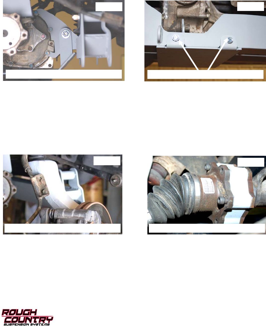
Photo 23
29. Install the differential bracket in the mounting tab on the back side of the front cross member and install the skid
plate as shown using the supplied 1/2” x 4 1/2” bolt, washers and nut. Install the rear of the skid plate by lining up the
holes in the cross-member and installing the supplied 3/8” self tapping bolts and tighten using a 9/16” wrench. See
Photo 24 & 25. Do not tighten hardware at this time. Pull the differential vent hose that was previously disconnected
down to install in the stock location and reinstall differential plug and wiring clips to the differential.
30. Install the lower control arms with the bump stop brackets attached in the new drop brackets with the factory hard-
ware (bolts install front to rear). Do not tighten control arm hardware at this time.
31. Tighten cross-member and differential drop bracket hardware at this time. Tighten 5/8” cross member hardware to
154 ft. lbs., 9/16” differential hardware to 114 ft. lbs., factory hardware on passenger differential bracket to 75ft-lbs.
32. Install the new knuckles with the stock ball joint hardware and tighten using a18mm & 24mm wrench.
33. Install the brake caliper with factory hardware. Using a 10mm wrench install the brake line on the knuckle. See
Photo 26. Tighten upper ball joint to 37 ft. lbs and lower to 94 ft. lbs. and tighten brake hardware. Reconnect the
ABS wire. If more slack is needed the line can be sprayed with 10-40 and the mounts slid down.
34. Install the stock shafts in the knuckle with factory hardware and using a 35mm socket. Locate the supplied CV spac-
ers and place the spacer in between the differential and the shaft as shown in Photo 27. Using Loc-Tite, secure
with the supplied 10mm x 65mm Socket head cap bolts with 8mm allen wrench. Tighten hardware to 58 ft.-lbs.
35. Install the tie rod end in the knuckle with the stock hardware and using a 19mm wrench. Tighten to 50 ft.-lbs.
Photo 24 Photo 25
Photo 26 Photo 27
Install the skid plate with supplied hardware Secure skid plate to rear cross-member
Install brake line to knuckle Install shaft spacers with supplied hardware
36. Install the supplied sway bar links as shown in Photo 28 using a 17mm wrench for the upper and 19mm for the
lower mount. Swivel end of link install in lower control arm. Tighten until bushings swell slightly.
37. Remove the stock torsion bar cross-member using a 21mm socket. See Photo 29.
38. To ease installation, install the factory torsion bars in the lower control arms and slide forward slightly. Locate new
torsion bar drop bracket over the factory rivets on the side of the frame rail and clamp in place. Using the bracket as
a guide, mark hole. Remove the bracket and drill holes using a 17/32” drill bit. See Photo 30.
39. Install the supplied bushings /sleeves in the bracket and install the torsion bar cross-member drop bracket with the
supplied 1/2” x 1 1/2” bolts & nuts. (4 bolts per side). Do not tighten at this time. See Photo 31.
40. Install the stock cross-member as shown in Photo 32 with factory hardware and using a 21mm wrench. Tighten
cross-member hardware using a 3/4” wrench.
41. Slide the torsion bars back into the cross-member with the stock torsion bar adjusters. Match mark made earlier to
properly clock the torsion bar adjuster and the torsion bar.
42. Using a torsion bar tool, load the torsion bars using the mark made earlier as a reference.
43. Locate the supplied front shock absorbers and assemble with bushings/sleeves. Install front shock part #658441 in
the factory lower location as shown in Photo 33 with factory hardware and using a 21mm wrench. Install the shock
in the upper mount with supplied stem bushings, cup washers & nuts using a 9/16” wrench.
44. Install the tires and wheels and jack up the vehicle to remove the jack stands. Lower the vehicle to the ground.
45. Tighten control arm hardware using a 18mm & 24mm wrench.
Photo 28 Photo 29
Photo 31
Photo 32
Photo 30
Photo 33
Install sway bar link Remove the torsion bar cross-member
Drill the frame rail Install torsion bar cross-member brackets
Install the stock cross-member on brackets Install shock absorbers
REAR INSTALLATION
1. Chock the front wheels and jack up the rear of the vehicle. Support the vehicle with jack stands. Remove the tires/
wheels using 7/8” deep well socket.
2. Remove the factory shocks using a 21mm wrench and discard.
3. Support the rear axle with a floor jack and remove the factory u bolts.
4. Install the block on the axle and make sure the block and axle pin align. See Photo 32.
5. Install the supplied 7/16” u-bolts, washers, and nuts on the leaf springs, securing the block to the springs. Do not
tighten at this time. See Photo 33.
6. Grinding may be required on the driver side e-brake
bracket on the lower shock mount. If needed grind
the threads to make sure there is no interference with
the shock absorber. This must be done if there is
interference with the shock. Failure to complete this
modification may damage the shock absorber body
and void all shock warranties.
7. Assemble the shocks part # 658556 with supplied
bushings /sleeves and install the new shocks with the
factory bolts and nuts using a 21mm wrench. See Photo
34. Note: The rear shock is a slim bore design due to
limited clearance between the shock body and the axle
tube.
8. Install the wheels and tires. Tighten lug nut to factory
specifications using crossing pattern. Lower the vehicle to
the ground.
9. Tighten the lug nuts to 85 ft lbs.
Photo 32
Photo 34
Photo 33
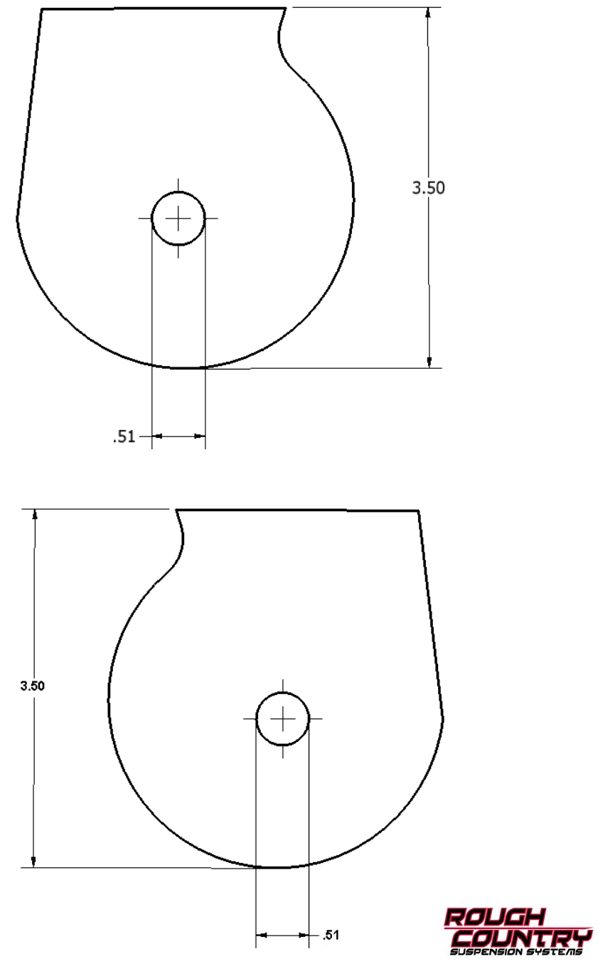
LOWER ARM TEMPLATE
(PLEASE CHECK TO MAKE SURE THE HOLE IS CENTERED PRIOR TO DRILLING)
PASS SIDE
DRIVER SIDE
Thank you for choosing Rough Country for all of your suspension needs.
POST INSTALLATION INSTRUCTIONS
1. Check all fasteners for proper torque. Check to ensure for adequate clearance between all rotating, mobile, fixed,
and heated members. Verify clearance between exhaust and brake lines, fuel lines, fuel tank, floor boards and wiring
harness. Check steering gear for clearance. Test and inspect brake system.
2. On some vehicles the front lower skirting will need to be trimmed if using certain wheel /tire combinations and with
heavy offset wheels. Trim only as needed.
3. Activate four wheel drive system and check front hubs for engagement.
4. Have a qualified alignment center align the vehicle immediately. Realign to factory specifications. Have headlights
adjusted to proper settings.
6. Perform head light check and adjustment to proper settings.
7. Check and retighten wheels at 50 miles and again at 500 miles.
8. Recheck lifted height and adjust torsion bar as necessary.
9. All kit components must be retightened at 500 miles and then every three thousand miles after installation. Periodi-
cally check all hardware for tightness.
10. Install “Warning to Driver” decal on sun visor.
Note: Installation of larger tires will require speedometer recalibration.
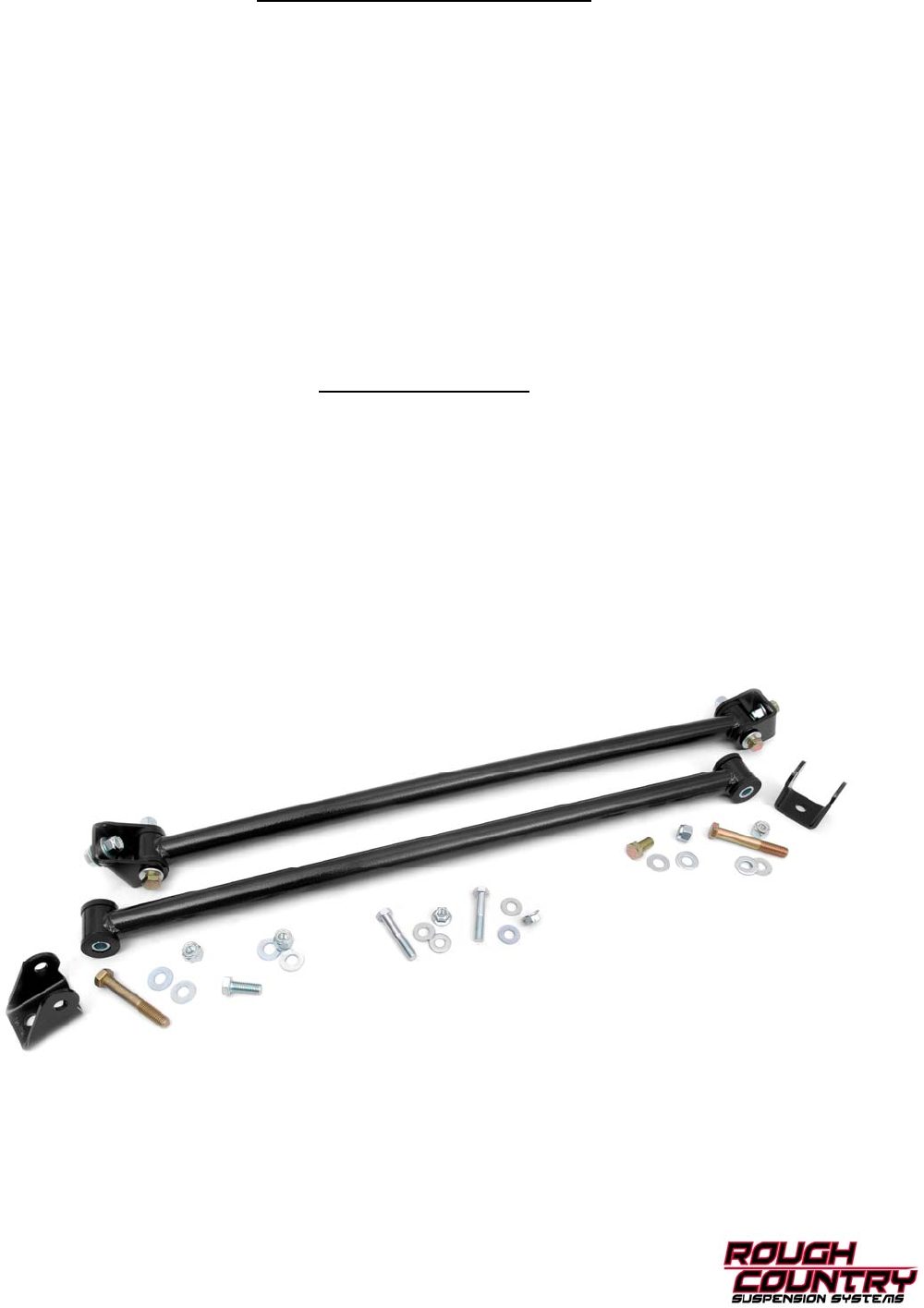
OPTIONAL EQUIPMENT
Rough Country offers two optional items for this vehicle when lifted with our suspension system. Both of these
items are highly recommended, but not required. Part # 87320 is a single steering stabilizer kit and will help
with 35” tires to reduce front end wonder and steering integrity. Also available is a set of kicker braces that add
stability to frame for off road performance. Please contact your Rough Country distributor to order.
Optional Equipment:
Part # 1272 Box4-Kicker Braces
