Rsc_555c Rsc 555c
rsc_92155700 rsc_92155700
rsc_556-22 rsc_556-22
rsc_557c rsc_557c
User Manual: Pdf rsc_555c
Open the PDF directly: View PDF ![]() .
.
Page Count: 22
2015-18 F-150 4”/5”/6” LIFT KIT
THANK YOU FOR CHOOSING ROUGH COUNTRY FOR YOUR SUSPENSION NEEDS.
Rough Country recommends a certified technician install this system. In addition to these instructions, professional
knowledge of disassemble/reassembly procedures as well as post installation checks must be known. Attempts to install
this system without this knowledge and expertise may jeopardize the integrity and/or operating safety of the vehicle.
Please read instructions before beginning installation. Check the kit hardware against the parts list. Be sure you have
all needed parts and know where they go. Also please review tools needed list and make sure you have needed tools.
PRODUCT USE INFORMATION
The taller a vehicle is, the easier it will roll. We strongly recommend, because of rollover possibility that
seat belts and shoulder harnesses should be worn at all times. Avoid situations where a side rollover may occur.
Generally, braking performance and capability are decreased when larger/heavier tires and wheels are
used. Take this into consideration while driving. Do not add, alter, or fabricate any factory or after-market parts to in-
crease vehicle height over the intended height of the Rough Country product purchased. Mixing component brands is not
recommended.
Rough Country makes no claims regarding lifting devices and excludes any and all implied claims. We will not be re-
sponsible for any product that is altered. If questions exist we will be happy to answer them concerning the design, func-
tion, and correct use of our products.
The 6”suspension system was developed using a 35X12.50/18 tire with 18 x 9 wheel with 4 1/2” back-
space. The lifts were designed to lift the front to level the vehicle. Due to manufacturing, dimension variances, and infla-
tion all tire and wheel combinations should be tested prior to installation on all oversized / wider then stock tires We rec-
ommend a wheel not exceeding 8" in width be used with a minimum backspacing of 4.5" to a maximum of 5". When us-
ing a stock wheel, it must be 18” or larger and the maximum tire width is 11 1/2”.
Vehicles will require the EPAS (Electronic Power Assist Steering) plugs to be disconnected prior
to beginning installation of this kit. See installation instructions. Failure to disconnect these plugs may result in
damage to the EPAS module resulting in an error message being displayed, which will require replacement of
the EPAS module DEALER AND VEHICLE OWNER
Any vehicle equipped with any Rough Country product should have a “Warning to Driver” decal installed on the inside of
the windshield or on the vehicle’s dash. The decal should act as a constant reminder for whoever is operating the vehi-
cle of its unique handling characteristics.
92155700H
5mm Allen Wrench
8mm Allen Wrench
8mm wrench /socket
10mm wrench /socket
12mm Wrench
13mm wrench / socket
15mm wrench /socket
16mm wrench /socket
18mm wrench /socket
19mm wrench /socket
21mm wrench /socket
22mm wrench /socket
24mm wrench /socket
30mm wrench /socket
Tools Needed:
Floor Jack
Jack stands
Reciprocating Saw
Hammer
9/16 wrench /socket
1 1/16” Wrench
Drill
1/4” Drill Bit
5/8” Drill Bit
11/32” Drill Bit
Torque Specs:
Size Grade 5 Grade 8
5/16” 15 ft/lbs 20 ft/lbs
3/8” 30 ft/lbs 35 ft/lbs
7/16” 45 ft/lbs 60 ft/lbs
9/16” 95 ft/lbs 130 ft/lbs
Class 8.8 Class 10.9
10MM 32ft/lbs 45ft/lbs
18MM 170ft/lbs 240ft/lbs
*1557BAG14*
1557BAG14

KIT CONTENTS
1557Bag8 Continued:
For Fr Dr Side Lower Diff Mount:
1-9/16” x 4” bolt
2-9/16” Flat Washers
1-9/16” Lock Nut
For Rr / RrCross-Member:
2-18mm x 150mm Bolts
4-18mm Flat Washers
2-18mm Lock Nuts
For Fr Drivers Side Diff Mount:
1-9/16” x 4” Bolt
2-9/16” Flat Washers
1-9/16’” Lock Nut
1557Bag6 Containing:
For Front Lower Control Arms:
4-18mm x 160mm Cam Bolts
4–Flat Washers
4-18mm Lock Nuts
For Front Skid Plate:
4-3/8” x 1” Bolt
4-3/8” Flat Washers
2-3/8” Nylock Nuts
For Front Driveshaft:
6-10mm x 85mm Allen Bolts
For Front Brake Line Bracket:
2-5/16” x 3/4” Bolt
2-5/16” Flat Washer
2-5/16” Lock Nut
For Sway Bar Brackets:
4-7/16” x 1.25’ Bolts
8-7/16’ Flat Washers
4-Lock Nuts
For Diff Tube:
1-Diff Tube Ext.
1-Tube Coupler
Kit Includes:
1557Box1:
1-Driver Side Knuckle
1557Box2:
1-Pass Side Knuckles
1555Box4:
1-Fr Cross-Member
1-Rr Cross-Member
1557Box15:
2-Dr & Pass Diff Bracket
1-Pass Side Diff Brace Bracket
1-Dr Side Sway Bar Bracket
1-Pass Side Sway Bar Bracket
2-Fr Brake Line Brackets
1-Front Lower Skid Plate
1-Rear E-Brake Bracket
1-Front Driveshaft Spacer
1-Rear Brake Line Bracket
1557Box12 or 13 (6”), 1556Box10 (5”), or
1555Box2 or 3 (4”)
2-Rear Blocks
2-Rear Shocks
2-Fr Strut Spacers (Not In Strut Kit)
4-Rear U-bolts
2-Rear Bump Stop Brackets
23033-4” Struts
23034-6” Struts
1557Bag8 Containing:
For Fr Dr Side Upper Diff Mount:
1– 9/16” x 4” Bolt
2-9/16” Flat Washers
1-9/16” Lock Nut
1- 1/2” x 1.5” Bolt
1- 1/2” Nylock Nut
2- 1/2” Flat Washer
10mm Stud Bag Containing:
For Front Strut Spacers:
6-10mm Studs
6-10mm Lock Washer
6-10mm Hex Nuts
1598Bag3 Containing:
For Rear Brake Line Brkt:
1-3/8” x 1’ Bolt
2-3/8” Flat Washers
1-3/8” Lock Nut
For Rear E-brake Bracket:
1-7/16” x 1” Bolt
2-7/16” Flat Washers
1-7/16” Lock Nut
1-5/16” x 3/4” Bolt
2-5/16” Flat Washers
1-5/16” Lock Nut
9/16Bag:
For Rear Blocks:
4-9/16” Axle U-Bolts
8-9/16” Nuts
8-9/16” Flat Washers
1263Bag2:
For Rear Blocks:
4-3/8” Spring U-Bolts
8-3/8” Nuts
8-3/8” Flat Washers
U-Bolt Bag For Anti-Wrap
Blocks:
4-7/16” x 3” U-Bolts
8-7/16” Nuts
8-7/16” Washers
1557Bag15:
For Pass Diff Brace :
2-12mm x 35mm
2-12mm Lock Nut
4-Flat Washers
6” Kit Shown in Picture
INSTALLATION INSTRUCTIONS
1. Chock the rear wheels and jack up the front of the vehicle.
2. Place jack stands under the frame rails and lower onto jack stands.
3. Remove the wheels/tires using a 21mm socket.
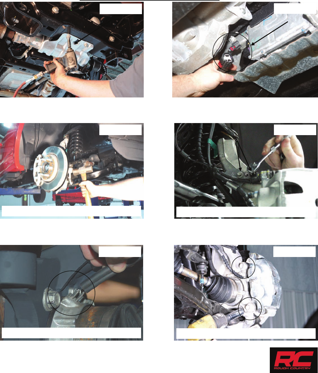
4. Remove the skid plate with a 13mm socket. See Photo 1.
5. Remove the EPAS (Electronic Power Assist Steering) Plugs as shown located on the steering assembly by the front
differential. See Photo 2. This must be done BEFORE installation is started.
6. Remove tie-rod end using a 21mm wrench. Using the appropriate tool remove the tie-rod from the knuckle. Photo 3.
7. Remove the ABS and brake line bracket from the knuckle using a 8mm wrench for the ABS wire and a 10mm
wrench for the brake line bracket. Retain hardware for reuse. See Photo 4.
8. Remove the vacuum line from the hub. See Photo 5.
9. Using a 19mm socket or 21mm socket, remove brake caliper as shown in Photo 6. Hang caliper out of way. Do not
let caliper hang by brake hose as this will damage hose. Retain hardware for reuse. Remove rotor.
PHOTO 3
PHOTO 5 PHOTO 6
PHOTO 4
TAP TO LOOSEN THE TIE ROD REMOVE BRACKET FROM KNUCKLE
REMOVE VACUUM LINE FROM HUB REMOVE THE CALIPER FROM KNUCKLE
PHOTO 1 PHOTO 2
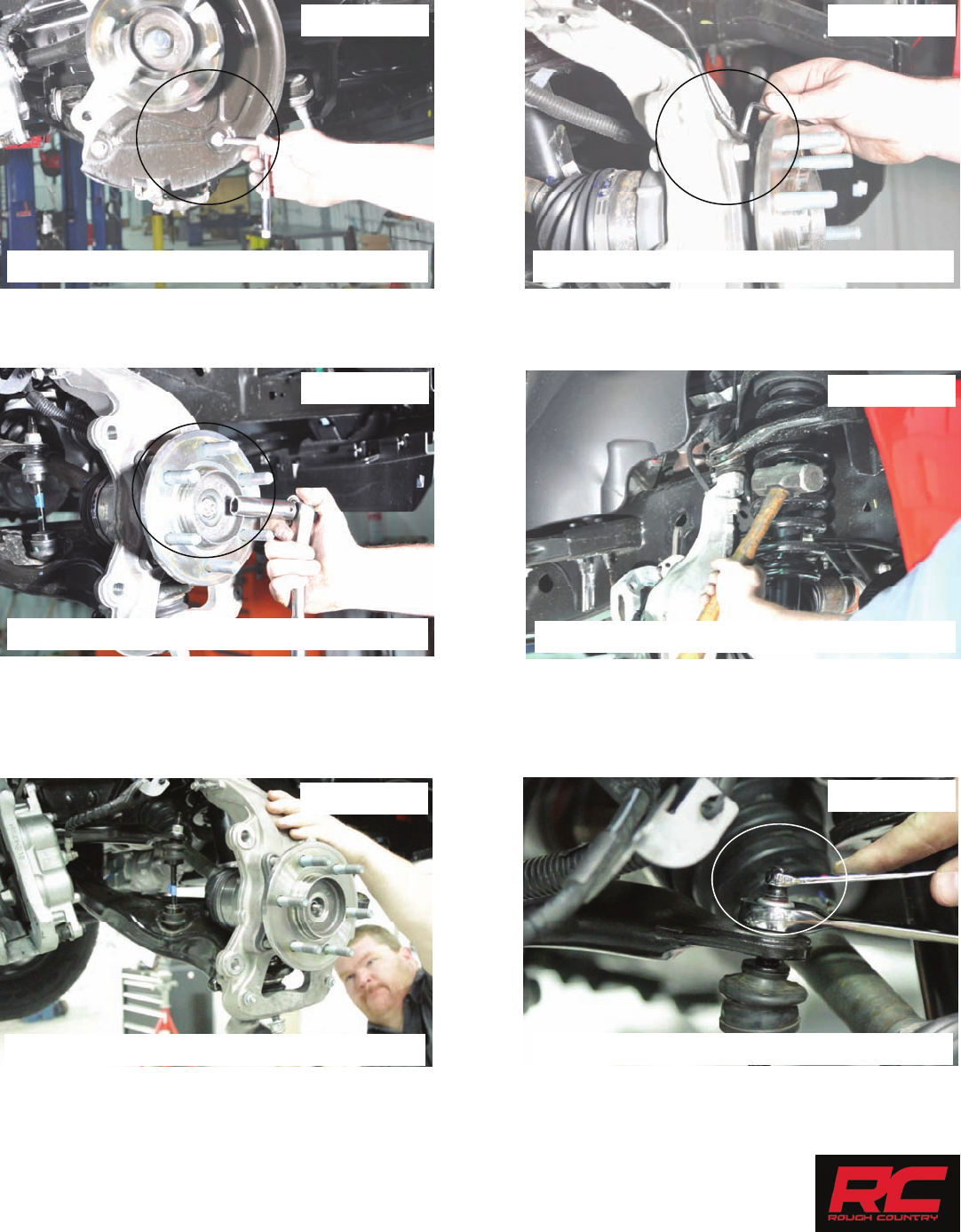
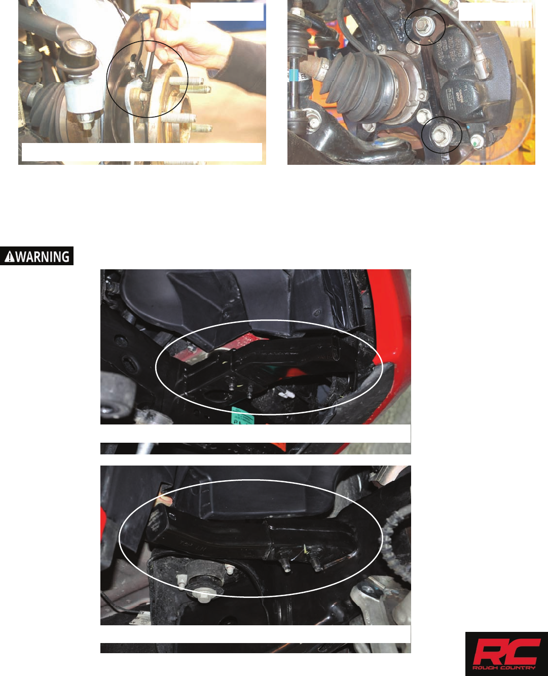
10. Remove the dust shield using a 8mm socket and dust cap. See Photo 7.
11. Remove the ABS wire from the bearing assembly using a 5mm allen wrench. See Photo 8.
12. Remove the axle nut using a 15mm socket. Retain hardware for reuse. See Photo 9.
13. Loosen the upper ball joint nut using a 21mm wrench. Use the appropriate tool to release ball joint from knuckle. See
Photo 10.
14. Loosen the lower ball joint using a 24mm wrench. Use the appropriate tool to release ball joint from knuckle. See
Photo 11.
15. Remove the upper and lower ball joint nuts and remove the knuckle from the vehicle.
16. Remove the sway bar links from the sway bar using a 8mm and 19mm wrench. Retain hardware for reuse. See
Photo 12.
PHOTO 7
REMOVE THE DUST SHIELD
PHOTO 8
REMOVE THE ABS WIRE
PHOTO 9 PHOTO 10
PHOTO 11 PHOTO 12
REMOVE THE AXLE NUT LOOSEN UPPER BALL JOINT
LOOSEN LOWER BALL JOINT REMOVE UPPER SWAY BAR HARDWARE
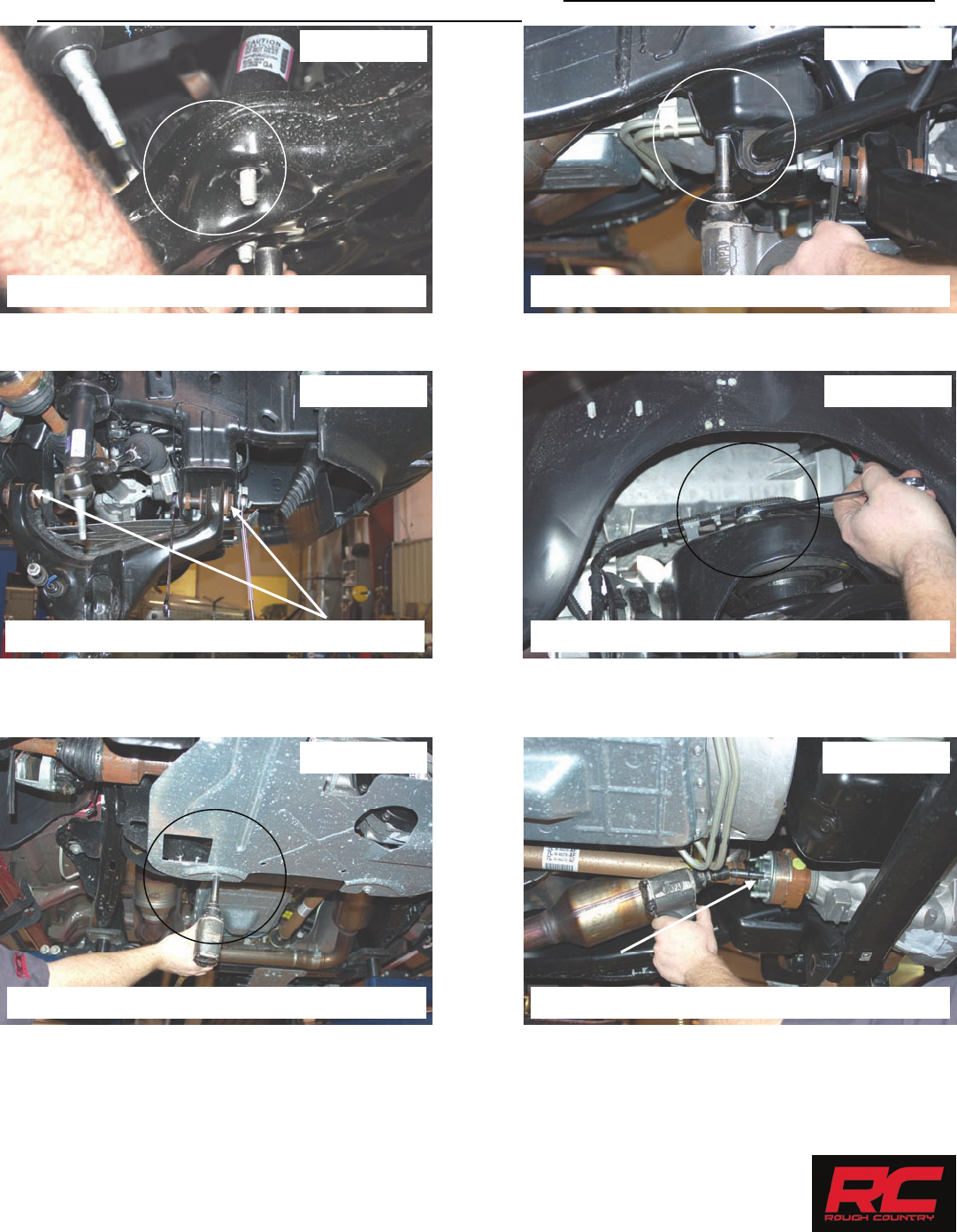
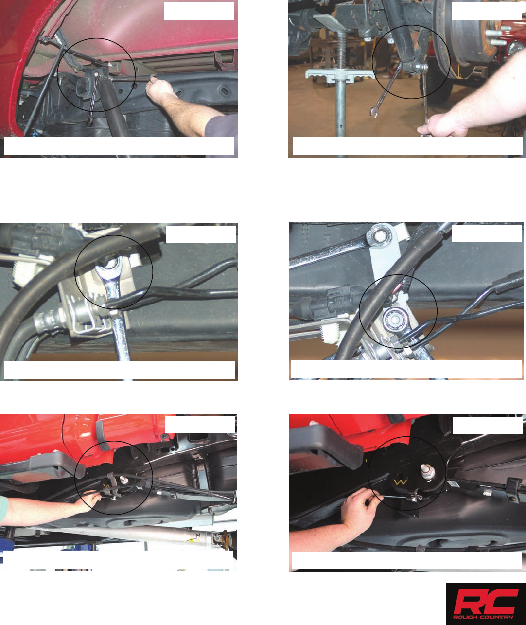
17. Remove the lower strut nuts using a 18mm socket. See Photo 13. Retain hardware for reuse.
18. Remove the sway bar from the frame mount using a 15mm socket. Please note the position that the sway bar is in-
stalled from the factory to make sure it is reinstalled correctly. Retain hardware for reuse. See Photo 14.
19. Remove the lower control arm using a 21mm and 1-1/16” wrench. Retain hardware for reuse. See Photo 15.
20. Remove the strut from the upper mount using a 15mm socket / wrench. Retain hardware for reuse. See Photo 16.
21. Remove the lower skid plate if equipped by removing the 4 bolts using a 13mm socket. See Photo 17.
22. Remove the driveshaft from the front differential using a 10mm socket. See Photo 18. Secure driveshaft out of the
way.
PHOTO 13 PHOTO 14
REMOVE THE LOWER STRUT NUTS REMOVE THE SWAY BAR FROM FRAME
PHOTO 15 PHOTO 16
PHOTO 17 PHOTO 18
REMOVE THE LOWER CONTROL ARM REMOVE THE UPPER STRUT HARDWARE
REMOVE THE LOWER SKID PLATE REMOVE THE DRIVE SHAFT

23. Remove the stock rear cross-member using a 15mm & 18mm socket. Retain hardware for reuse. See Photo 19.
2018 Models will have to make rear crossmember mount cuts in steps 26-30 before removing the
differential.
24. Support the differential using a floor jack and remove the upper driver side differential bolt using a 18mm wrench.
Retain hardware for reuse. See Photo 20.
25. Remove the differential vent tube from the differential.
26. Remove the passenger side differential bolt using a 18 & 21mm wrench. Retain hardware for reuse. See Photo 21.
27. Remove the lower rear driver side differential bolt using a 21mm socket / wrench. Lower and remove the differential
from the vehicle. Tape supplied cutting template on front and back side of the driver side lower cross-member
mount. Using template as a guide, trim cross-member mount to allow the differential to be removed. See Photo 22.
28. Tape supplied cutting template on front and back side of the driver side lower cross-member mount. Using template
as a guide, trim cross-member mount to allow the differential to be removed. See Photo 23.
29. Complete the trimming of the frame on the driver side using the template. See Photo 24.
PHOTO 19
REMOVE THE UPPER DRIVER DIFF BOLT
PHOTO 20
PHOTO 21
REMOVE THE DR UPPER DIFF BOLT
PHOTO 22
PHOTO 23 PHOTO 24
REMOVE THE REAR CROSS-MEMBER
INSTALL THE TEMPLATES AND CUT
REMOVE THE PASSENGER SIDE DIFF BOLT
CUT USING THE TEMPLATES
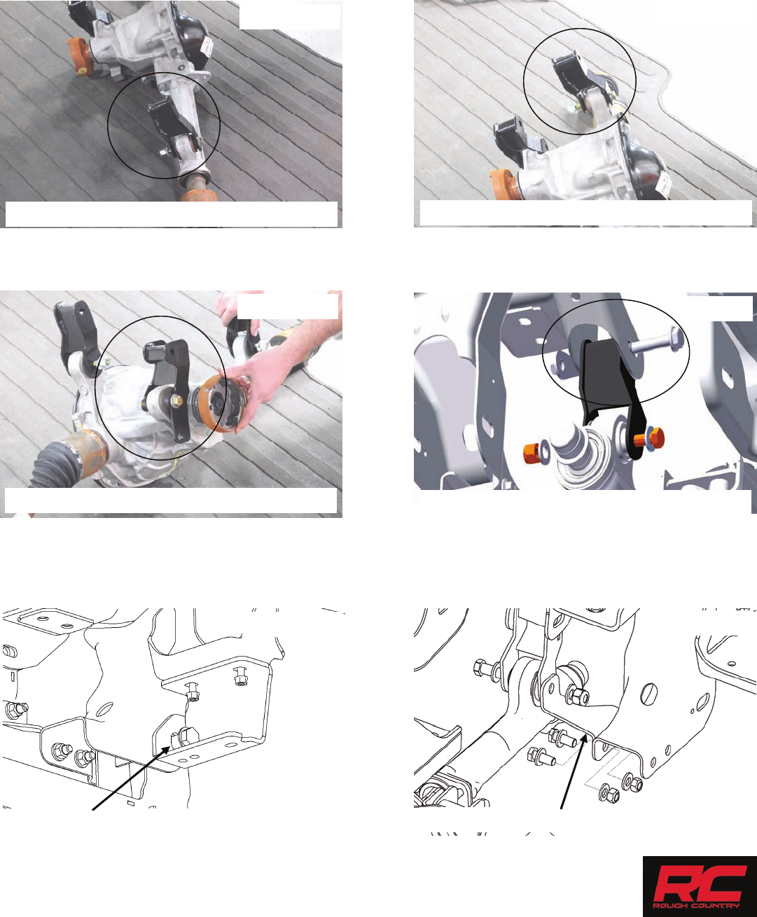
30. Install the new bracket on the passenger side diff mount (94003787) with the supplied hardware. Install the 9/16” x
4” bolt, washers & nut in the in the passenger side mount. See Photo 25.
31. Install the driver side diff mount (94003762C) with the supplied 9/16” x 4” bolt, washers and nut from the front to
rear. NOTE: The differential mounts bolts will need to be inserted from the front of the differential in order to
clear the rack and pinion. See Photo 26.
32. Install the rear diff mount using the supplied 9/16” x 4” hardware. See Photo 27.
33. Raise the differential into place and install the upper differential bolts using the stock hardware. See Photo 28. Do
not tighten at this time.
34. Install the rear cross-member with the supplied 18mm x150mm bolt. The bolt will install through the sway bar
bracket and rear cross-member, securing it to the stock location. Do not tighten at this time. See Photo 29.
35. Install the passenger side differential brace as shown in Photo 30 using the supplied 12mm hardware in
1557BAG15. Do not tighten at this time.
PHOTO 25 PHOTO 26
INSTALL THE PASS DIFF BRACKET INSTALL THE DR DIFF BRACKET
PHOTO 28
PHOTO 30
INSTALL THE DIFFERENTIAL
INSTALL THE PASS SIDE DIFF BRACE
PHOTO 27
INSTALL THE REAR DIFF BRACKET
INSTALL RR CROSSMEMBER /SWAY BAR BRKTS
PHOTO 29
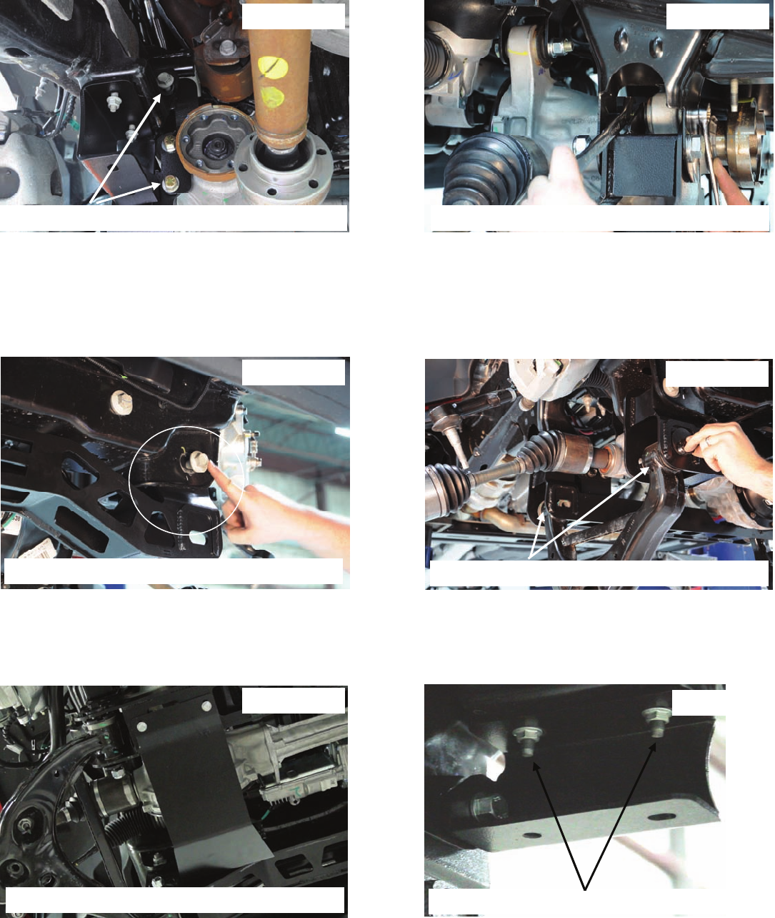
36. Attach the rear diff mount to the cross member using the supplied 7/16” hardware. Attach to upper mount using fac-
tory hardware. See Photo 31.
37. Tighten the diff bolt with a 21mm and 22mm wrench. See Photo 32.
38. At this time tighten all diff bolts using 18mm socket / wrench for the upper diff bolts and a 21mm & 22mm socket /
wrench for the new supplied lower diff bolts. Also tighten the passenger side diff brace hardware using a 15mm &
18mm socket /wrench.
39. Reinstall the vent tube on the differential with the new supplied vent tube extension 1557Bag2.
40. Install the front cross-member using the factory hardware. See Photo 33. Do not tighten at this time.
41. Install the lower control arms using the supplied 18mm x 160mm cam bolts, washers and nuts. See Photo 34. Do
not tighten at this time.
42. Install the new skid plate in the rear cross member threaded holes using the supplied 3/8” x 1” bolts, washers. At-
tach to the front cross member using the supplied 3/8” x 1” bolts, washers and nylock nuts from 1557BAG6. See
Photo 35. Tighten using a 9/16” socket and wrench.
43. Tighten all upper cross-member bolts using a 21mm, 1 1/16” socket and 1 1/16” wrench.
44. Tighten the sway bar drop mounts to the frame using the factory hardware with a 15mm socket. See Photo 36.
PHOTO 31 PHOTO 32
PHOTO 34
PHOTO 35 PHOTO 36
INSTALL THE DR SIDE LOWER REAR DIFF BOLT TIGHTEN DIFF BOLTS
INSTALL THE STOCK CONTROL ARMS
INSTALL THE SKID PLATE TIGHTEN THE SWAY BAR BRACKETS
PHOTO 33
INSTALL THE FRONT CROSS-MEMBER
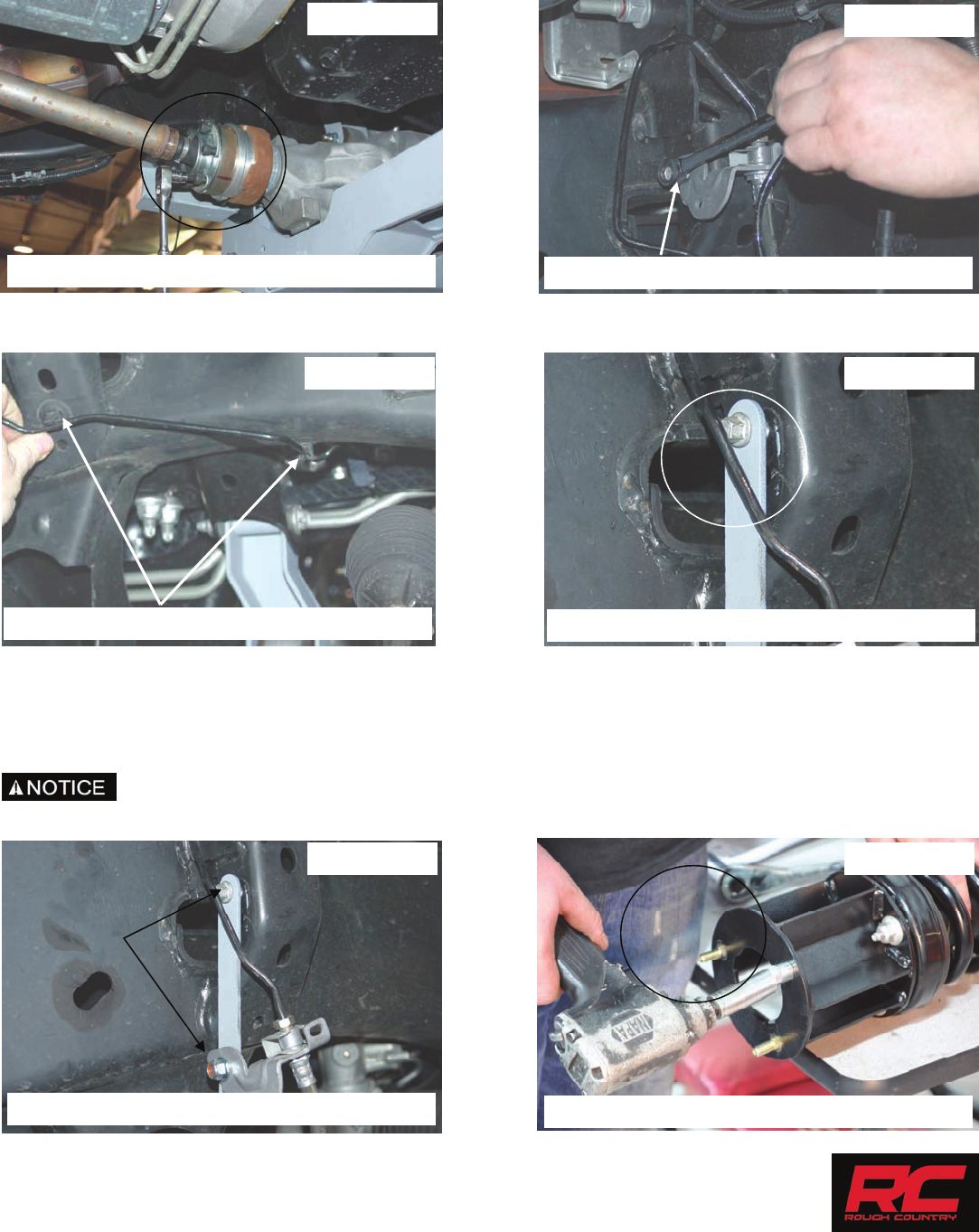
45. Install the drive shaft spacer with supplied 10mm x 85mm hardware. See Photo 37. Tighten using a 8mm allen
wrench.
46. Using a 10mm wrench remove the brake line bracket from the driver and pass side frame. See Photo 38.
47. On the passenger side remove the brake line from the two factory clips. See Photo 39.
48. Install the new brake line bracket on the driver and passenger side with the stock hardware. See Photo 40.
49. Install the factory passenger side brake line in the new bracket using the supplied 5/16’ x 3/4” bolt, washer and nuts.
See Photo 41.
50. On the driver side, pull slightly on the brake line to allow the line to be installed on the new bracket. Secure the brake
line to the new bracket with the supplied 5/16” x 3/4” bolt, washers and nut.
51. Using a 13mm socket / wrench, tighten the supplied brake line hardware and 10mm for the stock hardware.
If installing new lifted struts, follow supplied strut instructions and skip to step 56.
52. Install the supplied 10mm studs in the strut spacers with a 17mm wrench as shown in Photo 42.
PHOTO 37 PHOTO 38
INSTALL THE DRIVE SHAFT SPACER REMOVE THE BRAKE LINE BRACKET
PHOTO 39 PHOTO 40
PHOTO 42
REMOVE THE STEEL LINE FROM MOUNTS INSTALL THE BRAKE LINE BRACKET
INSTALL THE 3/8” STUDS IN SPACER
PHOTO 41
REINSTALL THE BRAKE LINE TO BRACKET
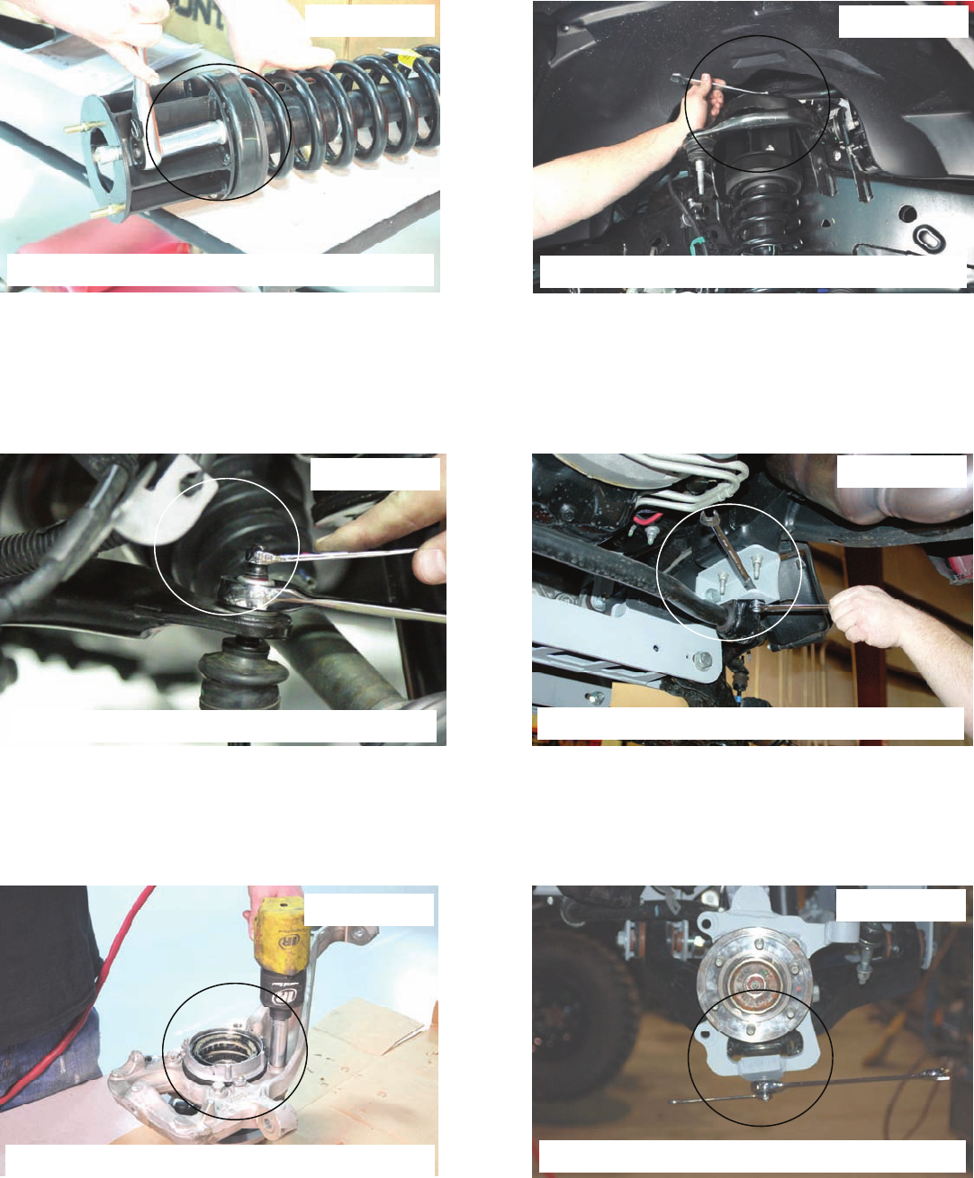
53. Using the stock hardware, install the strut spacers on the struts. Tighten using a 15mm socket. See Photo 43.
54. Install the strut with strut spacers installed in the stock upper mount. Secure with supplied 10mm nuts, washers and
lock washers. See Photo 44. Do not tighten at this time.
55. Install the lower strut in the lower control arm using the factory hardware. Tighten using a 18mm socket.
56. Tighten upper strut mount hardware using 17mm wrench.
57. Install the sway bar body on the sway bar links located on the lower control arms. Install nut to hold the sway bar in
place but do not tighten at this time. See Photo 45.
58. Swing up the sway bar and install on the sway bar drop brackets using the supplied 7/16” x 1” bolts, washers and
nuts. Tighten using a 18mm on the sway bar drop hardware and 18mm wrench on sway bar links on the lower con-
trol arms. See Photo 46.
59. Remove the stock bearing assembly from the stock knuckle using a 18mm for the bearing and a 8mm for the locking
hub mechanism. Install the bearing assembly on the lifted knuckle using the stock hardware. Tighten using a 18mm
wrench. See Photo 47.
60. Install the new knuckles using the stock hardware on the lower ball joints, tighten using 24mm and a 12mm wrench.
See Photo 48. Do not use air impact on the upper and lower ball joint, tighten with hand tools.
PHOTO 43 PHOTO 44
PHOTO 45 PHOTO 46
PHOTO 47
INSTALL THE SPACER TO THE STRUT INSTALL THE ASSEMBLY IN UPPER MOUNT
REINSTALL THE SWAYBAR ON CONTROL ARM REINSTALL THE SWAYBAR ON BRACKETS
REMOVE BEARING AND HUB
PHOTO 48
INSTALL KNUCKLE ON LOWER BALL JOINT

We recommend using OE instructions for disassembly and assembly of IWE actuator, the follow-
ing instructions are for reference only.
61. Install IWE actuator on CV shaft.
Make sure the actuator splines line up to the splines on the CV shaft. See photo 49.
62. Install CV shaft into the knuckle assembly. See Photo 50.
63. Using a floor jack, raise the lower control arm and connect the upper ball joint on the upper control arm to the spin-
dle. Using a 21mm wrench, torque to manufacturer specs. If ball joint turns while tightening, use a 3/8” wrench to
hold the ball joint.
64. Reinstall the steering linkage nut using a 21mm wrench.
65. Using a hand vacuum pump, apply and hold 24inHG of vacuum to the actuator through the large port. See Photos
51 and 52.
Photo 49 Photo 50
Photo 51 Photo 52
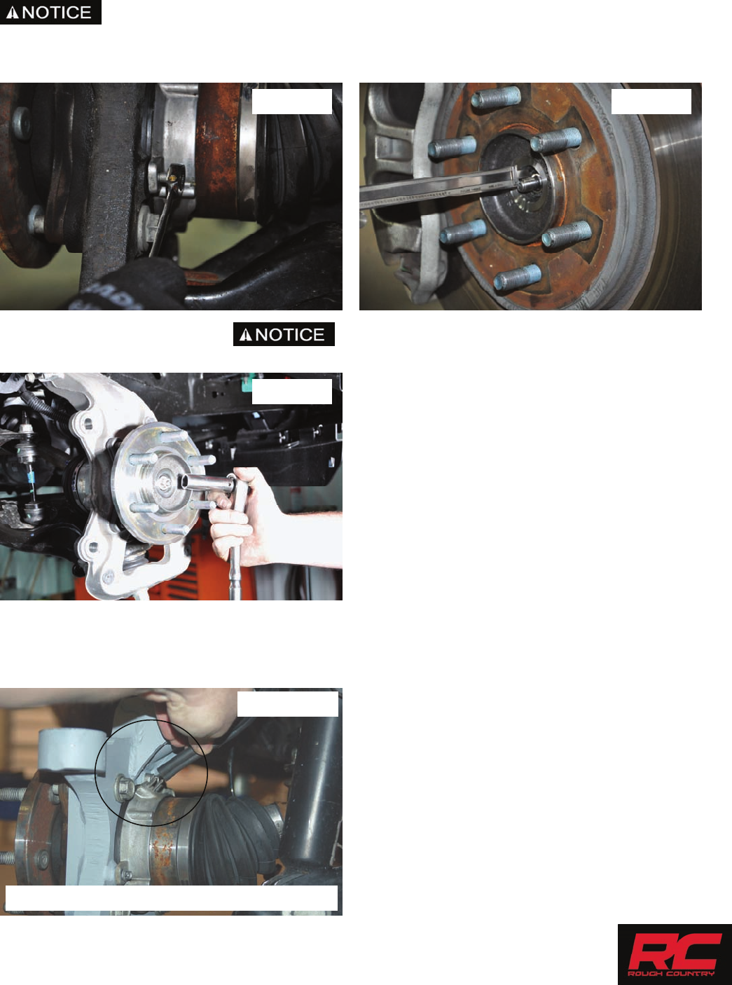
PHOTO 56
REINSTALL THE VACUUM LINE TO HUB
66. Install the (3) bolts securing the actuator to the knuckle and tighten using an 8mm wrench. See Photo 53.
67. With vacuum still applied to actuator. Measure the depth of the CV shaft treads protruding through
the hub bearing. If minimum 15.5mm or .61” is not achieved, rotate the hub to eliminate binding of the splines.
See Photo 54.
68. Install axle nut and tighten to 30 lb.ft. Do Not Use and impact, caution must be taken or damage to
shaft may occur. See Photo 55.
69. Verify free rotation of the hub with NO CV shaft rotation. No clicking or grinding noise should be present
70. Release the vacuum from the actuator and rotate the hub to engage the actuator. You may hear/feel the actuator
engage.
71. Verify that the hub and CV rotate together. Reconnect the vacuum lines to the actuator. See Photo 56.
Photo 53 Photo 54
Photo 55
72. Install the ABS wire on the bearing assembly using a 5mm allen wrench. See Photo 57. NOTE: The factory dust
shield will not be reused.
73. Install the rotor and caliper on the knuckle with the stock hardware using a 19mm or 21mm wrench. Tighten hard-
ware. See Photo 58.
74. Make sure the vacuum hose and ABS wire are out of harms way. Using the supplied zip tie, secure the vacuum
hose and ABS wire to the knuckle neck.
75. Install the tires and wheels using a 21mm socket. Remove the jack stands and lower the truck to the ground.
76. Tighten the lower control arm bolts using a 1-1/16” wrench and socket. Torque to 240 ft/lbs.
Do not cut or remove factory crash bar if equipped.
PHOTO 57
REINSTALL THE ABS WIRE TO HUB
PHOTO 58
Front crash bar.
Rear crash bar.
REAR INSTALLATION
1. Chock the front tires and jack the rear the rear end up. Put jack stand under the frame rail and lower truck onto jack
stands.
2. Remove tires and wheels using a 21mm socket.
3. Remove rear shocks from the upper and lower mount using 18mm and a 15mm wrench. See Photo 1 & 2. Retain
the stock hardware.
4. Using a 10mm wrench, remove the brake line assembly on the inner driver side frame rail. See Photo 3.
5. Install the brake line extension bracket on the frame using the stock hardware and tighten using a 10mm wrench.
See Photo 4.
6. Install the brake line assembly to the new bracket using the supplied 3/8” x 1” bolt, washers and nut. Tighten using a
9/16” socket and wrench. See Photo 4.
7. Remove the e-brake cable mount with a 10mm wrench as shown on the drivers side as shown in Photo 5.
8. Install the supplied e-brake bracket with the factory hardware. Tighten with a 10mm wrench. See Photo 6.
PHOTO 1 PHOTO 2
PHOTO 3 PHOTO 4
PHOTO 5 PHOTO 6
REMOVE THE SHOCK FROM THE FRAME REMOVE THE SHOCK FROM THE AXLE
REMOVE THE BRAKE BRACKET FROM FRAME REINSTALL THE BRACKET TO NEW BRACKET
REMOVE E-BRAKE MOUNT INSTALL DROP BRACKET ON FRAME
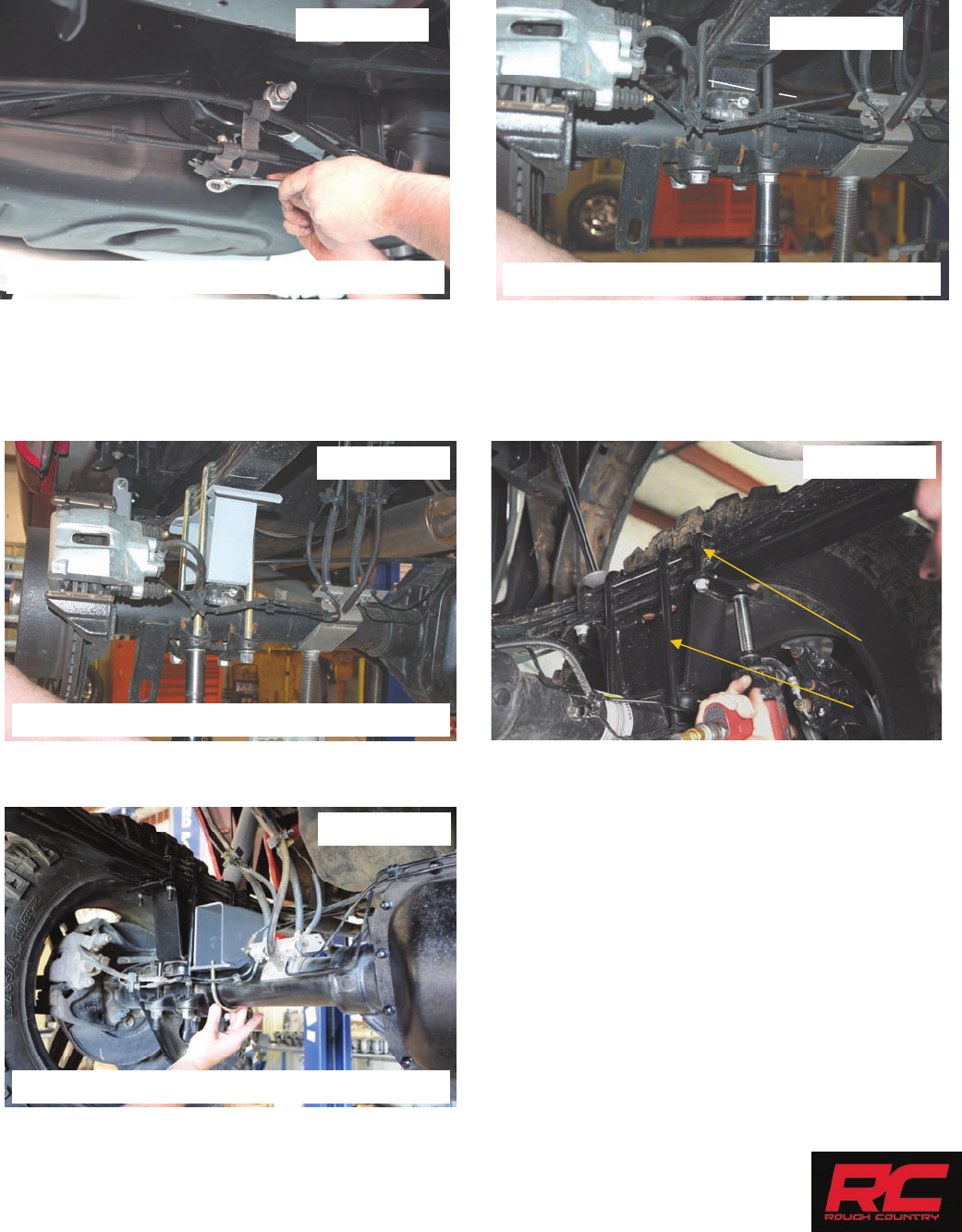
9. Install the e-brake cable mount to the new e-brake drop bracket using the supplied 5/16” bolt, washers, and lock nut.
See Photo 7.
10. Using a jack support the rear end and remove U-bolts using a 21mm socket and remove the factory blocks. Retain
factory block for the 4” kit. See Photo 8.
11. Install the supplied blocks on the block pin holes on the axle and raise the axle into place. See Photo 9. Note the 4”
kit will have a standard block with the factory block while the 5”/6” kit will use the Rough Country Anti-wrap design
blocks. Note- Taller end of block to the rear of the truck!
12. Install the axle u-bolts and tighten using a 22mm socket.
13. For the 5”/6” kits install the upper leaf spring u-bolts over the leaf spring and into the blocks. Secure with supplied
hardware and tighten using a 16mm socket. See Photo 10.
14. Install the supplied rear bump stop bracket if supplied with the 3/8” x 3.5” round u-bolt. Tighten with the 3/8” nylock
nuts and a 9/16” socket. See Photo 11.
PHOTO 8
PHOTO 7
INSTALL NEW BRACKET REMOVE FACTORY U-BOLTS AND BLOCK
PHOTO 11
INSTALL BUMP STOP AND U-BOLT
INSTALL BLOCKS AND U-BOLTS
7/16”
9/16”
PHOTO 10
PHOTO 9

15. Install the new shock absorbers in the upper and lower mounts using the stock hardware. Tighten using a 18 and
15mm wrench. Shocks will mount with the body down.
16. Install the tire and wheels.
17. Raise up the rear of the vehicle and remove the jack stands. Lower the vehicle to the ground.
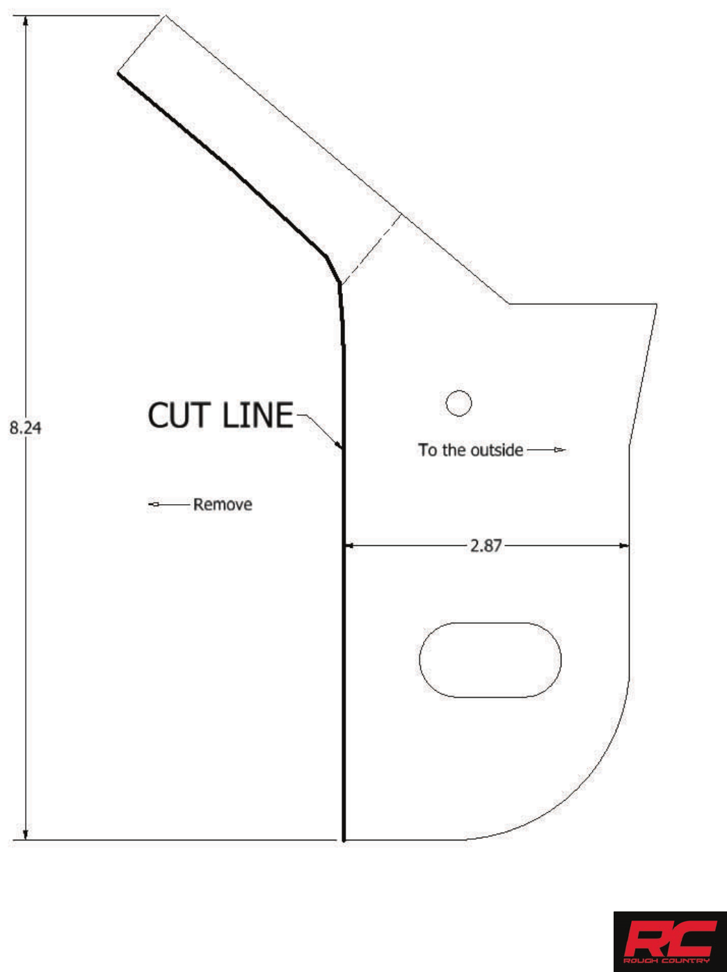
CUTTING / DRILLING TEMPLATE—FR SIDE OF DRIVER CROSS-MEMBER
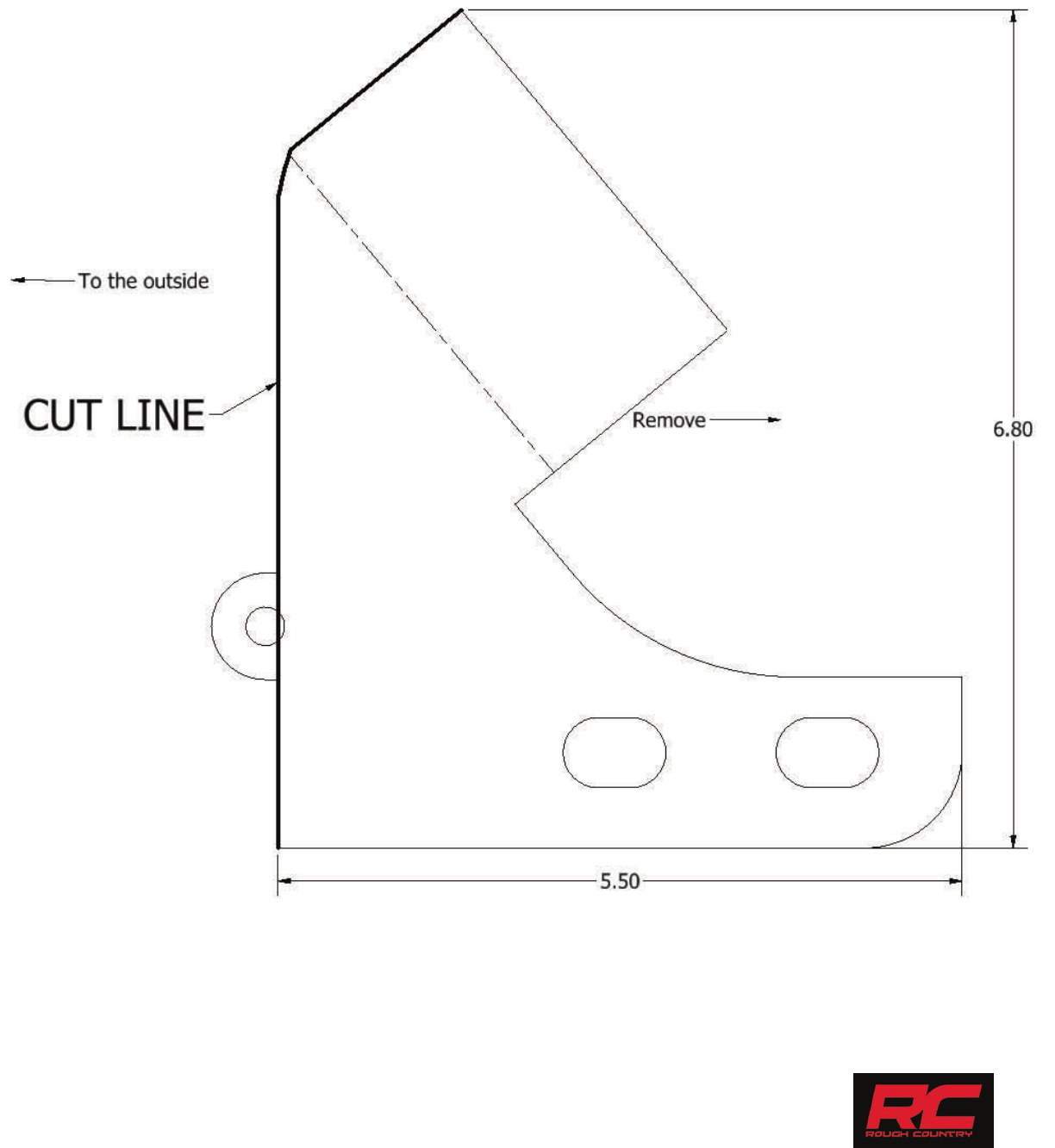
CUTTING / DRILLING TEMPLATE—REAR OF DRIVER SIDE CROSS-MEMBER

POST INSTALLATION INSTRUCTIONS
1. Check all fasteners for proper torque. Check to ensure there is adequate clearance between all rotating, mobile,
fixed and heated members. Check steering gear for interference and proper working order. Test brake system
2. Perform steering sweep. Check to ensure brake hoses have sufficient slack and will not contact rotating, mobile, or
fixed members, adjust lines/brackets to eliminate interference and maintain proper working order. Failure to perform
inspections may result in component failure
3. Readjust headlights to factory settings
4. Have vehicle aligned by a certified alignment professional.
5. Re-torque all nuts, bolts, and especially u-bolts after the first 100 miles, again after another 100 miles and then check
periodically thereafter
6. All components must be retightened after 500 miles, and every three thousand miles after installation.
By purchasing any item sold by Rough Country, LLC, the buyer expressly warrants that he/she is in compliance with all
applicable , State, and Local laws and regulations regarding the purchase, ownership, and use of the item. It shall be
the buyers responsibility to comply with all Federal, State and Local laws governing the sales of any
items listed, illustrated or sold. The buyer expressly agrees to indemnify and hold harmless Rough
Country, LLC for all claims resulting directly or indirectly from the purchase, ownership, or use of the
items.
Thank you for purchasing a Rough Country Suspension System.
