CONVERT Series650
User Manual: Pdf series650
Open the PDF directly: View PDF ![]() .
.
Page Count: 20
Installation, Operating & Maintenance Instructions
Series 650, DN 63-250 (I.D. 2.5"-10")
VAT Vakuumventile AG, CH-9469 Haag, Switzerland
Tel +41 81 771 61 61 Fax +41 81 771 48 30 CH@vatvalve.com www.vatvalve.com 235015EI
2010-01-11 1/20
Pendulum Control & Isolation Valve
with stepper drive actuator
This manual is valid for the valve ordering number(s):
ISO-F Flange JIS Flange ASA-LP Flange
DN63 65036 - P. 52 - . . . . 65036 - J. 52 - . . . . 65036 - T. 52 - . . . .
DN100 65040 - P. 52 - . . . . 65040 - J. 52 - . . . . 65040 - T. 52 - . . . .
DN160 65044 - P. 52 - . . . . 65044 - J. 52 - . . . . 65044 - T. 52 - . . . .
DN200 65046 - P. 52 - . . . . 65046 - J. 52 - . . . . 65046 - T. 52 - . . . .
DN250 65048 - P. 52 - . . . . 65048 - J. 52 - . . . . 65048 - T. 52 - . . . .
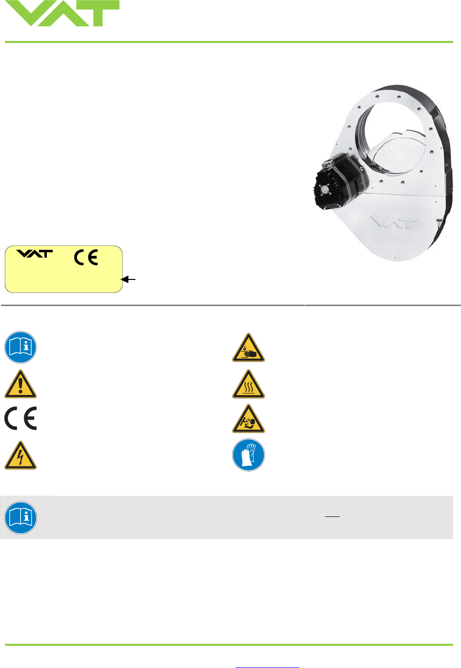
The fabrication number is indicated on each product as per the label below
(or similar):
made in Switzerland
Fabrication No.: patented . .
650
. . – . .
52
– . . . . / . . . .
A
– . . . . . .
Fabrication number
Sample photo
Explanation of symbols:
Read declaration carefully before you start any other
action!
Keep body parts and objects away from the valve
opening!
Attention!
Hot surfaces; do not touch!
Product is in conformity with EC guidelines,
if applicable!
Loaded springs and/or air cushions are potential
hazards!
Disconnect electrical power and compressed air
lines. Do not touch parts under voltage!
Wear gloves!
Read these «Installation, Operating & Maintenance Instructions» and the enclosed «General
Safety Instructions» carefully before you start any other action!

Installation, Operating & Maintenance Instructions
Series 650, DN 63-250 (I.D. 2.5"-10")
VAT Vakuumventile AG, CH-9469 Haag, Switzerland
Tel +41 81 771 61 61 Fax +41 81 771 48 30 CH@vatvalve.com www.vatvalve.com 235015EI
2010-01-11 2/20
Contents:
1 Use of product .......................................................................................................................................................... 3
1.1 Technical data.................................................................................................................................................... 3
2 Installation................................................................................................................................................................. 4
2.1 Unpacking .......................................................................................................................................................... 4
2.2 Installation procedure......................................................................................................................................... 4
2.2.1 Install valve into system........................................................................................................................... 4
2.2.2 Connect compressed air.......................................................................................................................... 7
2.2.3 Connect VAT controller............................................................................................................................ 7
2.2.4 Connect intermediate pumping port......................................................................................................... 7
2.2.5 Connect heating device ........................................................................................................................... 7
3 Operation .................................................................................................................................................................. 8
3.1 Normal operation................................................................................................................................................ 8
3.2 Operation under increased temperature ............................................................................................................ 8
3.3 Behavior in case of compressed air pressure drop............................................................................................ 8
3.4 Behavior in case of power failure....................................................................................................................... 8
4 Maintenance & repairs.............................................................................................................................................. 9
4.1 Preventive maintenance procedures................................................................................................................ 10
5 Drawing................................................................................................................................................................... 15
6 Spare parts ............................................................................................................................................................. 16
7 Trouble shooting..................................................................................................................................................... 18
8 Warranty ................................................................................................................................................................. 19
9 Appendix A – Micro switch configuration of motor driver ........................................................................................ 20
9.1 For valves with actuator position B1 ................................................................................................................ 20
9.2 For valves with actuator position B2 ................................................................................................................ 20

Installation, Operating & Maintenance Instructions
Series 650, DN 63-250 (I.D. 2.5"-10")
VAT Vakuumventile AG, CH-9469 Haag, Switzerland
Tel +41 81 771 61 61 Fax +41 81 771 48 30 CH@vatvalve.com www.vatvalve.com 235015EI
2010-01-11 3/20
1 Use of product
This product is a throttling pendulum valve with isolation functionality. It is intended to use for downstream pressure
control applications. Use product for clean and dry indoor vacuum applications under the conditions indicated in chapter
«Technical data» only! Other applications are only allowed with the written permission of VAT.
1.1 Technical data
Pressure range at 20°C
• blank (650 . . - . A52 - . . . . )
• hard anodized (650 . . - . H52 - . . . . )
1 x 10⁻⁸ mbar to 1.2 bar (abs)
1 x 10⁻⁶ mbar to 1.2 bar (abs)
Leak rate to outside at 20°C
• blank (650 . . - . A52 - . . . . )
• hard anodized (650 . . - . H52 - . . . . )
1 x 10⁻⁹ mbar ls-1
1 x 10⁻⁵ mbar ls-1
Leak rate valve seat at 20°C
• blank (650 . . - . A52 - . . . . )
• hard anodized (650 . . - . H52 - . . . . )
1 x 10⁻⁹ mbar ls-1
1 x 10⁻⁴ mbar ls-1
Cycles until first service
• isolation cycles (open - closed - open)
• throttling cycles (open - max. throttle - open)
200’000 (unheated and under clean conditions)
1 Mio. (unheated and under clean conditions)
Compressed air supply
4…7bar (55…100psi)
Admissible operating temperature
• actuator ambient
• valve body
35 °C max.
10...150 °C
Mounting position any (valve seat on chamber side is recommended)
Wetted materials valve body, pendulum
plate
sealing ring
other parts
seals
Aluminum 3.2315 (AA6082)
Aluminum 3.2315 (AA6082),
1.4306 (304L)
1.4435 (316L), 1.4404 (316L), 1.4122,
1.4310 (301), 1.4303 (304), 1.4571
Viton® (standard). Other materials
available.
Seal materials are declared on
dimensional drawing of specific valve
ordering number.
Max. differential pressure on plate during isolation 1200 mbar in either direction
DN63 / 2.5”_DN100./.4”
(65036(40) - . . 52 - . . . . ) DN160 / 6”
(65044 - . . 52 - . . . . ) DN200 / 8”
(65046 - . . 52 - . . . . ) DN250 /10"
(65048 - . . 52 - . . . . )
Max. differential pressure on plate
during
opening and throttling
30 mbar 10 mbar 5 mbar 5 mbar
Min. controllable conductance (N2
molecular flow) 3 ls-1 5 ls-1 10 ls-1 15 ls-1
Closing time throttling only 0.9 s typ. 1.1 s typ. 1.1 s typ. 1.3 s typ.
Opening time throttling only 0.9 s typ. 1.1 s typ. 1.1 s typ. 1.3 s typ.
Closing time throttling & isolation 3 s typ. 3 s typ. 3 s typ. 3 s typ.
Opening time throttling & isolation 4 s typ 4 s typ. 4 s typ. 4 s typ.
Operation Only with VAT Controller (VM-6, PM-6, PM-7 or PM-7E) and VAT
connection cable.
Dimensions Refer to dimensional drawing of specific valve ordering number
(available on request).
Installation, Operating & Maintenance Instructions
Series 650, DN 63-250 (I.D. 2.5"-10")
VAT Vakuumventile AG, CH-9469 Haag, Switzerland
Tel +41 81 771 61 61 Fax +41 81 771 48 30 CH@vatvalve.com www.vatvalve.com 235015EI
2010-01-11 4/20
2 Installation
2.1 Unpacking
As this valve is a heavy component you should lift it with adequate equipment to prevent any injury to
humans.
DN200 (8”) and DN250 (10”) valves are equipped with attachment points (tapped holes). Add eyebolts
to these attachment points for lifting. The attachment points are indicated on the dimensional drawing of
the specific valve part number (available on request).
Never lay the valve down with actuator downwards as the actuator may be damaged.
2.2 Installation procedure
Fingers and objects must be kept out of the valve opening and away from moving parts.
The valve plate may start to move just after power is supplied.
Do not connect or disconnect sensor cable when device is under power.
Do not disconnect air supply when device is under power.
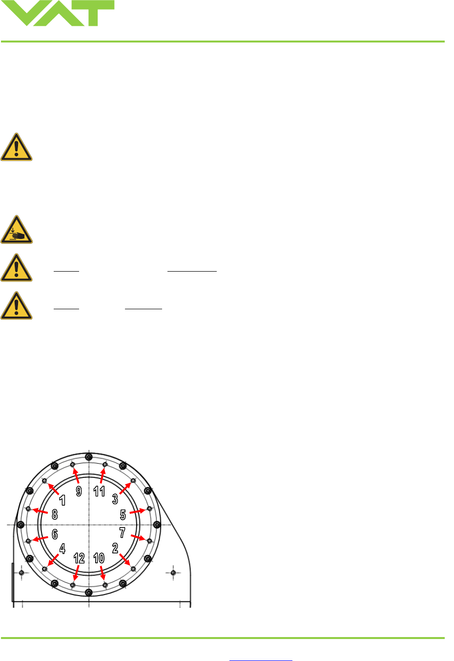
2.2.1 Install valve into system
• Valve seat side should face process chamber. The valve seat side is indicated by the symbol "∇" on the valve
flange.
• The valve is a heavy component you should lift it with adequate equipment for installation into system
Note:
• Make sure that enough space is kept free to do preventive maintenance work. The required space is indicated on
the dimensional drawing.
• Make sure that the valve is not hanging at screws while installation
• If you use a body flange compl. (S650_DN200, ISO-F) see figure below
Note:
• Screw in all screws and tighten by hand
• Fasten all screws by numbers from 1 to12 uniformly
step by step, and according with tables on page 5 & 6
(max. tighening torque Nm).
Installation, Operating & Maintenance Instructions
Series 650, DN 63-250 (I.D. 2.5"-10")
VAT Vakuumventile AG, CH-9469 Haag, Switzerland
Tel +41 81 771 61 61 Fax +41 81 771 48 30 CH@vatvalve.com www.vatvalve.com 235015EI
2010-01-11 5/20
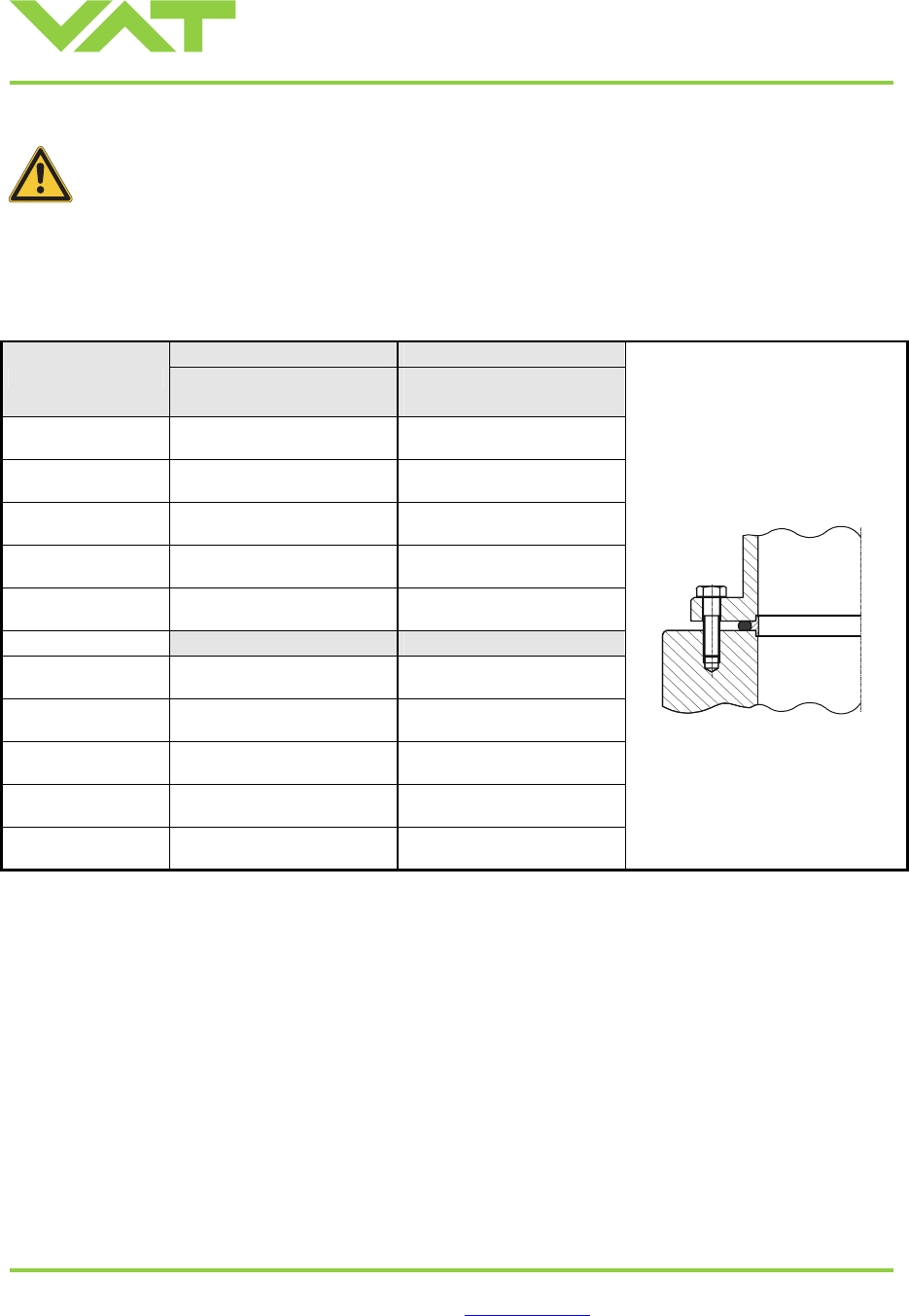
Do not tighten flange screws stronger than indicated in the tables below. The max. tightening torque
depends on the type of installation.
Note: Tighten mounting screws of the flanges uniformly in crosswise order. Observe the maximum torque levels in
the following tables (a, b + c). Higher tightening torques deforms the valve body and may lead to malfunction of the
valve.
a) Mounting with centering ring
ISO-F ISO-F
Valve size max. tightening torque
(Nm) max. tightening torque
(lbs . ft)
DN63 / 2.5“
(65036 - . . 52 - . . . . )
8 – 10 6 - 8
DN100 / 4“
(65040 - . . 52 - . . . . ) 8 – 10 6 - 8
DN160 / 6“
(65044 - . . 52 - . . . . ) 13 – 15 9 - 11
DN200 / 8“
(65046 - . . 52 - . . . . ) 13 – 15 9 - 11
DN250 / 10“
(65048 - . . 52 - . . . . ) 17 – 20 13 – 15
hole depth (mm) hole depth (inch)
DN63 / 2.5“
(65036 - . . 52 - . . . . )
12 0.47
DN100 / 4“
(65040 - . . 52 - . . . . ) 12 0.47
DN160 / 6“
(65044 - . . 52 - . . . . ) 14 0.55
DN200 / 8“
(65046 - . . 52 - . . . . ) 15 0.59
DN250 / 10“
(65048 - . . 52 - . . . . ) 16 0.63
Note: Use slightly lubricated screws and make sure that screws are not too long otherwise the valve body may be
damaged. Refer to chapter «Spare parts» for centering ring ordering numbers.
Installation, Operating & Maintenance Instructions
Series 650, DN 63-250 (I.D. 2.5"-10")
VAT Vakuumventile AG, CH-9469 Haag, Switzerland
Tel +41 81 771 61 61 Fax +41 81 771 48 30 CH@vatvalve.com www.vatvalve.com 235015EI
2010-01-11 6/20
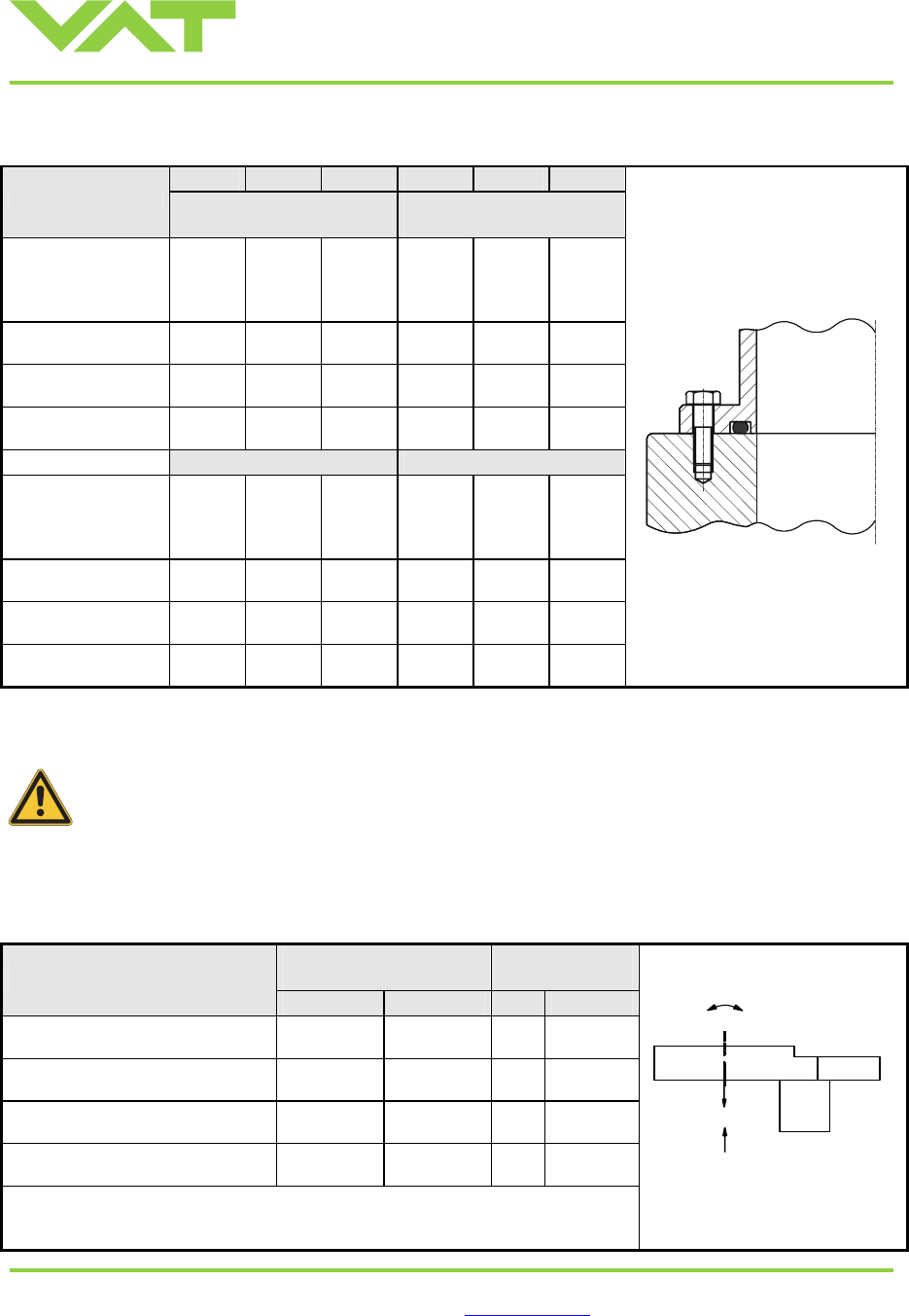
b) Mounting with O-ring in groove
ISO-F JIS ASA-LP
ISO-F JIS ASA-LP
Valve size max. tightening torque
(Nm) max. tightening torque
(lbs . ft)
DN63 / 2.5“
(65036 - . . 52 - . . . . )
DN100 / 4“
(65040 - . . 52 - . . . . )
20-23 35-40 35-40 15 - 17 26 - 30 26 - 30
DN160 / 6“
(65044 - . . 52 - . . . . ) 35-40 35-40 35-40 26 - 30 26 - 30 26 - 30
DN200 / 8“
(65046 - . . 52 - . . . . ) 35-40 35-40 80-90 26 - 30 26 - 30 59 - 67
DN250 / 10“
(65048 - . . 52 - . . . . ) 35-40 65-70 80-90 26 - 30 48 - 52 59 – 67
hole depth (mm) hole depth (inch)
DN63 / 2.5“
(65036 - . . 52 - . . . . )
DN100 / 4“
(65040 - . . 52 - . . . . )
12 12 12 0.47 0.47 0.47
DN160 / 6“
(65044 - . . 52 - . . . . ) 14 14 14 0.55 0.55 0.55
DN200 / 8“
(65046 - . . 52 - . . . . ) 15 15 14 0.59 0.59 0.59
DN250 / 10“
(65048 - . . 52 - . . . . ) 16 16 16 0.63 0.63 0.63
Note: These torques are valid if depth of the mounting screws is min. 1 x thread diameter. Make sure that screws in use
are capable to withstand applied torques. Also use slightly lubricated screws and make sure that screws are not too long
otherwise the valve body may be damaged.
Do not admit higher forces to the valve than indicated in the table below.
c) Admissible forces
Forces from evacuating the system, from the weight of other components, and from baking can lead to deformation and
malfunctioning of the valve. Stress has to be relieved by suitable means, e.g. bellows sections.
Axial tensile or
compressive force «FA» Bending
moment «M»
Valve size
N lb. Nm lbf.
DN63 / 2.5” (100 / 4“)
(65036(40) - . . 52 - . . . . ) 1000 220 40 30
DN160 / 6“
(65044 - . . 52 - . . . . ) 2000 440 80 60
DN200 / 8“
(65046 - . . 52 - . . . . ) 2000 440 80 60
DN250 / 10“
(65048 - . . 52 - . . . . ) 2500 550 100 75
For a combination of both forces (FA and M) the values are invalid.
Verify that the depth of the mounting screws is min. 1 x thread diameter.
Please contact VAT for more information.
F
A
M
Installation, Operating & Maintenance Instructions
Series 650, DN 63-250 (I.D. 2.5"-10")
VAT Vakuumventile AG, CH-9469 Haag, Switzerland
Tel +41 81 771 61 61 Fax +41 81 771 48 30 CH@vatvalve.com www.vatvalve.com 235015EI
2010-01-11 7/20
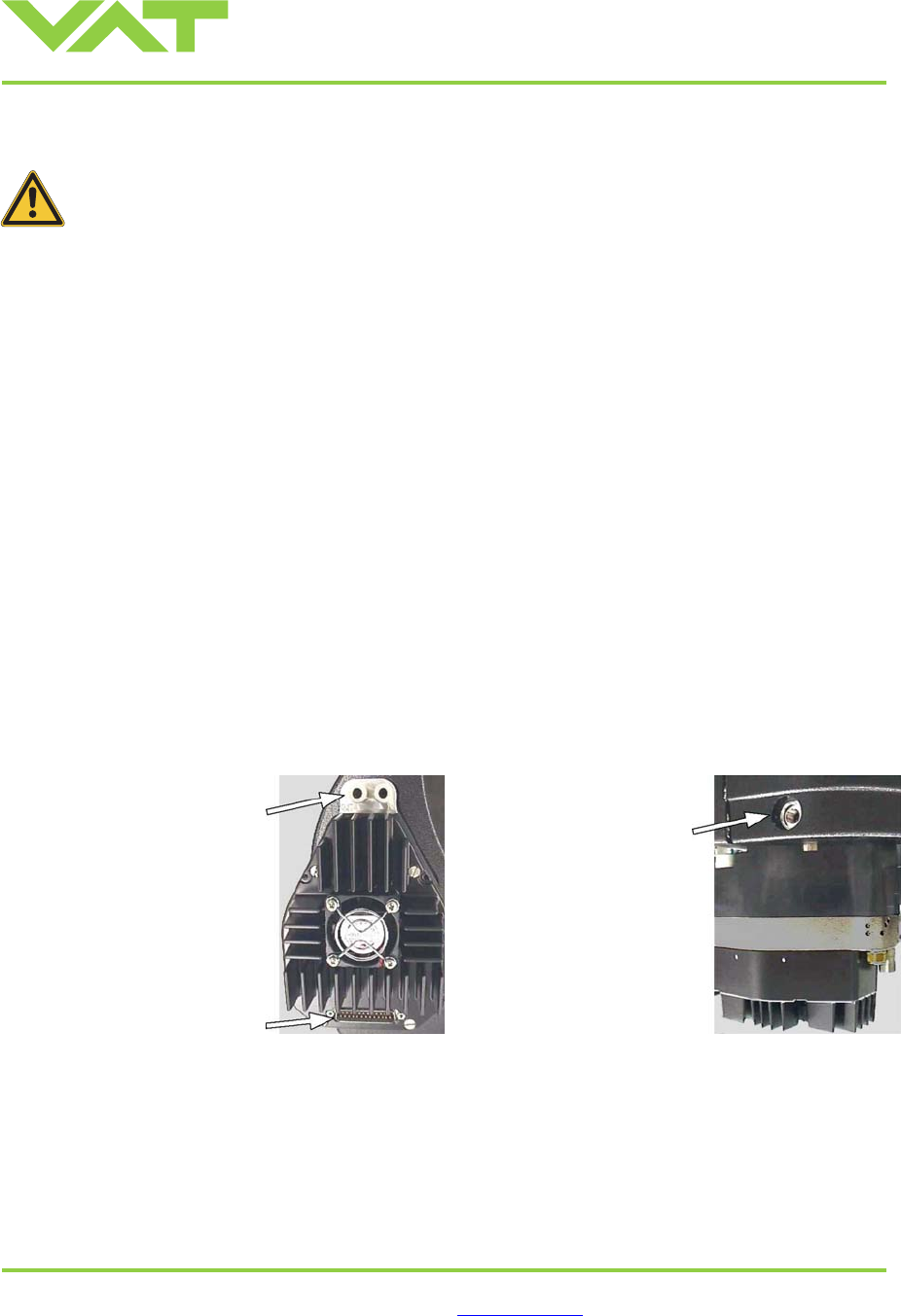
2.2.2 Connect compressed air
Compressed air pressure (above ATM) must be in the range of: 4 - 7 bar / 55 - 100 psi. Use only clean,
dry or slightly oiled air.
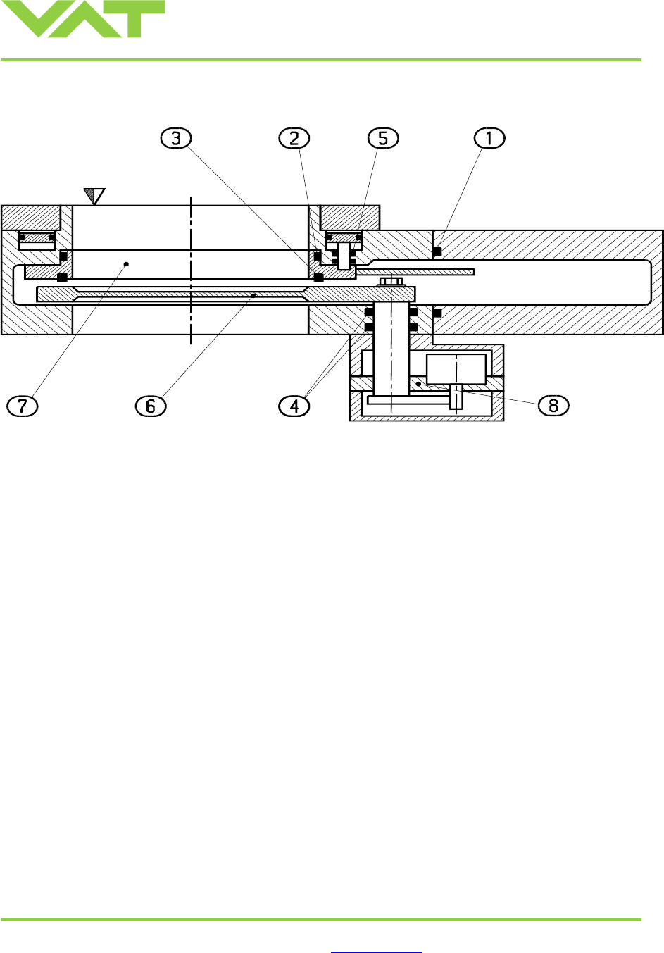
• Connect compressed air supply to actuator connection labeled ‘IN’
• Connect compressed air return line to actuator connection labeled ‘OUT’
• IN / OUT connections are 1/8“ ISO/NPT internal threads. Refer to Figure 1.
2.2.3 Connect VAT controller
• The VAT controller has to be turned off for at least 60 seconds before connecting/disconnecting it to/from the valve.
• Connect valve to VAT controller (650PM - . . . . or 650VM - . . . . ) by using the VAT connection cable (650CV-99L . ).
Refer to Figure 1.
• Install VAT Controller according to the manual of the controller.
2.2.4 Connect intermediate pumping port
• This valve has a double sealed rotary feed through with intermediate pumping port for the actuator. Refer to drawing on
page 15.
• Optional: Connect vacuum line to this intermediate pumping port (1/8“ ISO/NPT). Refer to Figure 2.
2.2.5 Connect heating device
This valve may be optionally equipped with a heating device. Connect VAT heating device according to manual of the
heating device.
IN: compressed air supply
OUT: return line
connector for VAT controller
intermediate
pumping port
Figure 1
Figure 2
Installation, Operating & Maintenance Instructions
Series 650, DN 63-250 (I.D. 2.5"-10")
VAT Vakuumventile AG, CH-9469 Haag, Switzerland
Tel +41 81 771 61 61 Fax +41 81 771 48 30 CH@vatvalve.com www.vatvalve.com 235015EI
2010-01-11 8/20
3 Operation
Operation is allowed after completion of the installation procedure only.
3.1 Normal operation
This valve may be operated only with a VAT controller and a VAT cable. For operation details other than those mentioned
below refer to the manual of the VAT controller.
Do not operate the valve if the differential pressure between both valve sides is higher than the value specified in chapter
«Technical data». Otherwise the valve may be damaged and malfunction is caused.
3.2 Operation under increased temperature
Refer to chapter «Technical data»
3.3 Behavior in case of compressed air pressure drop
Valve position before
compressed air pressure drop: Reaction of valve:
Valve closed Valve remains closed.
Valve open or in any intermediate
position Sealing ring moves down and blocks the pendulum plate at the current position.
VAT controller with display indicates ‚COMPRESSED AIR FAILURE‘. Refer to
the manual of the VAT controller for details.
3.4 Behavior in case of power failure
Reaction of valve:
Valve position before
power failure: When operated by a VAT Controller with
Power Failure Option When operated by a VAT Controller
without Power Failure Option
Valve closed Valve remains closed.
VAT controller with display indicates
‚POWER FAILURE‘. Refer to the
manual of the VAT controller for details.
Valve remains closed.
Valve open or in any intermediate
position Valve will close *)
VAT controller with display indicates
‚POWER FAILURE‘. Refer to the
manual of the VAT controller for details.
Sealing ring moves down and blocks
the pendulum plate at the current
position.
*) Provided that the battery pack of the VAT controller is charged, refer to the manual of the VAT controller for details.
Installation, Operating & Maintenance Instructions
Series 650, DN 63-250 (I.D. 2.5"-10")
VAT Vakuumventile AG, CH-9469 Haag, Switzerland
Tel +41 81 771 61 61 Fax +41 81 771 48 30 CH@vatvalve.com www.vatvalve.com 235015EI
2010-01-11 9/20
4 Maintenance & repairs
Under clean operating conditions, the valve does not require any maintenance during the specified cycle life.
Contamination from the process may influence the function and requires more frequent maintenance.
Before carrying out any maintenance or repairs, please contact VAT. It has to be individually decided whether the
maintenance/repair can be performed by the customer or has to be carried out by VAT. The fabrication number on the
valve
made in Switzerland
Fabrication No.: patented . .
. . . . . – . . . . – . . . . / . . . .
A
– . . . . . .
Fabrication number
has always to be specified.
All supplies (e. g. compressed air, electrical power) must be disconnected for removal/installation of the valve from/into
the system and for maintenance work.
Even with disconnected supply, loaded springs and/or air cushions in cylinders can be potential hazards.
Keep fingers and objects away from the valve opening!
Products returned to VAT must be free of harmful substances such as e.g. toxical, caustic or microbiological ones. If
products are radioactively contaminated, fill in the VAT form «Contamination and Radiation Report» and send it with the
product. The form is available at VAT. The maximum values indicated in the form must not be exceeded.
Installation, Operating & Maintenance Instructions
Series 650, DN 63-250 (I.D. 2.5"-10")
VAT Vakuumventile AG, CH-9469 Haag, Switzerland
Tel +41 81 771 61 61 Fax +41 81 771 48 30 CH@vatvalve.com www.vatvalve.com 235015EI
2010-01-11 10/20
4.1 Preventive maintenance procedures
Keep fingers out of the valve body during preventive maintenance work. The sealing ring or its retaining
pins will lower in case of electrical power failure or loss of compressed air.
Take precautions to protect yourself from harmful substances that may have contaminated the valve
during use.
Two preventive maintenance procedures are defined for this valve. These are:
• Replacement of isolation seals (gate and body seal of sealing ring) and valve cleaning
• Replacement of actuator shaft seals
Required frequency of cleaning and replacement of seals is depending on process conditions.
A critical factor influencing the maintenance period is the lifetime of the vacuum grease, being limited under
increased temperature. In this case grease will separate to PTFE and oil. The oil may flow and contaminate
the valve parts.
VAT can give the following recommendations for preventive maintenance:
unheated *) heated ≤ 80°C *) heated > 80°C *)
isolation seals (gate and body seal of sealing ring) 200’000 cycles 6 months 3 months
actuator shaft seals 1 Mio. cycles 6 months 3 months
*) These figures are reference values for clean conditions under various temperatures. These values do not include any
impact of the process. Therefore preventive maintenance schedule has finally to be checked for the actual process
conditions.
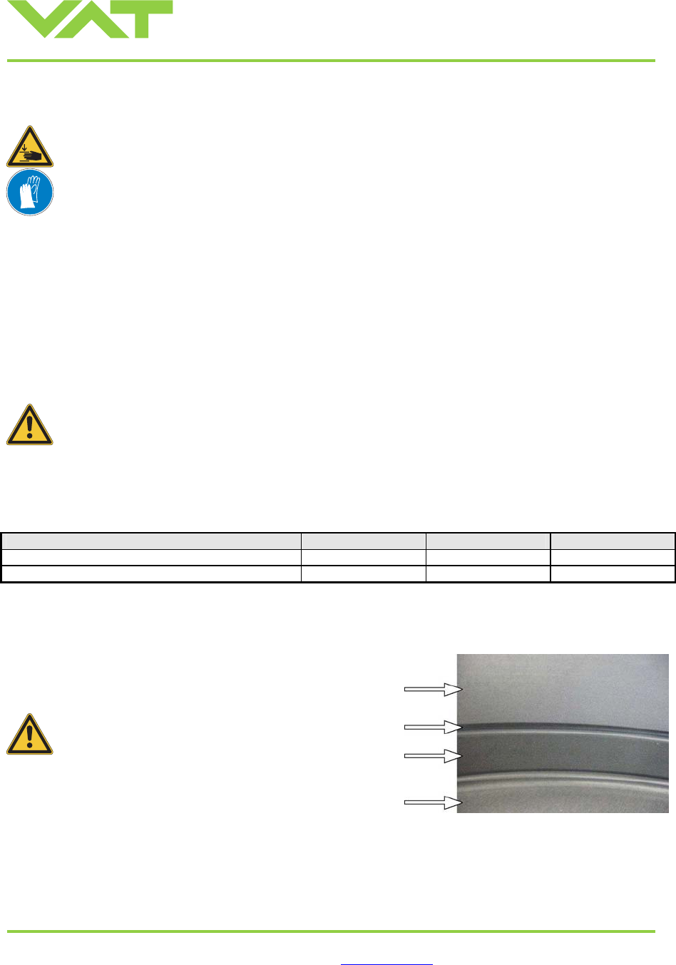
Prevent gap between body and sealing
ring from air gun cleaning. Otherwise
vacuum grease may be distributed and
contaminate the valve.
valve body
gap
sealing ring
pendulum plate
Installation, Operating & Maintenance Instructions
Series 650, DN 63-250 (I.D. 2.5"-10")
VAT Vakuumventile AG, CH-9469 Haag, Switzerland
Tel +41 81 771 61 61 Fax +41 81 771 48 30 CH@vatvalve.com www.vatvalve.com 235015EI
2010-01-11 11/20
Replacement of isolation seals (gate and body seal of sealing ring) and valve cleaning
Replacement of actuator feed through seals
D e s c r i p t i o n Required tool
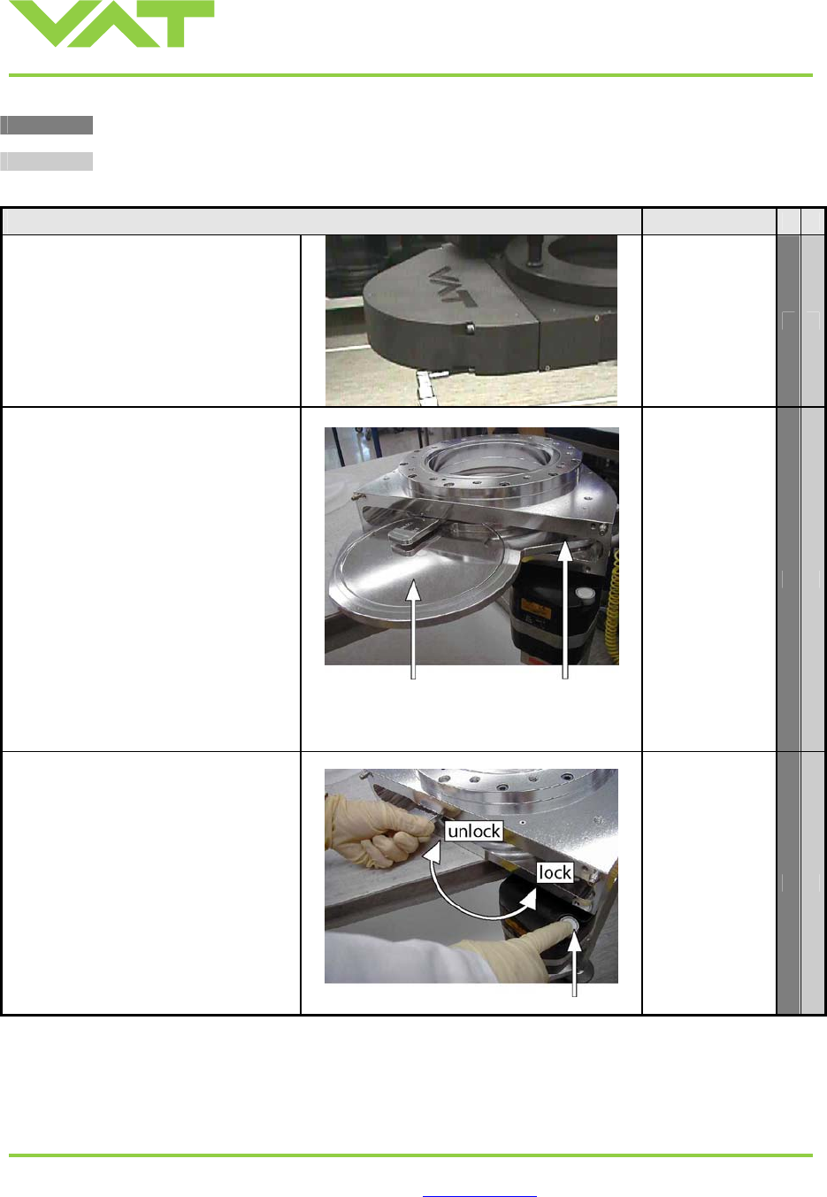
1. Vent both valve chambers.
2. Open bonnet screws and remove
valve bonnet.
Allen wrench
5mm
3. Give ‘OPEN’ command on VAT
controller to bring pendulum plate to
OPEN position.
Caution: Stand away from valve –
pendulum plate moves out of the
valve body.
4. To prevent the pendulum plate from
moving during work, switch the VAT
controller to maintenance mode.
Refer to the manual of the VAT
controller for details.
5. Unfasten mounting screw for
pendulum plate.
6. Remove pendulum plate.
pendulum plate mounting screw
for pendulum plate
open end wrench
13mm
7. With one hand press the
MAINTENANCE BUTTON to lower
the sealing ring, with your second
hand unlock the sealing ring by
pressing the handle.
8. Release MAINTENANCE BUTTON.
9. Remove sealing ring.
maintenance button
Installation, Operating & Maintenance Instructions
Series 650, DN 63-250 (I.D. 2.5"-10")
VAT Vakuumventile AG, CH-9469 Haag, Switzerland
Tel +41 81 771 61 61 Fax +41 81 771 48 30 CH@vatvalve.com www.vatvalve.com 235015EI
2010-01-11 12/20
D e s c r i p t i o n Required tool
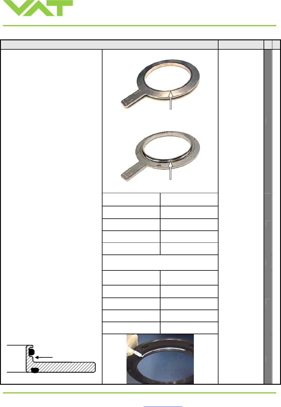
gate seal
10. Remove gate and body o-ring from
sealing ring carefully with a soft tool.
11. Remove grease residues at sealing
ring with alcohol.
Clean sealing ring and pendulum
plate with alcohol or in an ultrasonic
bath.
12. Clean out valve body with alcohol.
Use an appropriate non metal tool
with a cloth to enter valve body.
Do not enter valve body with hands!
Then blow out valve body with clean
air.
Do not directly expose seals
(actuator and retaining pin see-
through) to air stream!
13. Clean or replace gate seal if
necessary.
Install gate o-ring to sealing ring
without grease.
body seal
Valve size Quantity of grease
[ml]
DN63 / 2.5” (100 / 4“)
(65036(40) - . . 52 - . . . . )
0.1
DN160 / 6“
(65044 - . . 52 - . . . . ) 0.15
DN200 / 8“
(65046 - . . 52 - . . . . ) 0.2
14. Clean or replace body seal if
necessary.
Lubricate body o-ring with the
quantity of vacuum grease listed in
the table to the right.
DN250 / 10“
(65048 - . . 52 - . . . . ) 0.2
15. Install body o-ring into sealing ring.
Valve size Quantity of grease
[ml]
DN63 / 2.5” (100 / 4“)
(65036(40) - . . 52 - . . . . )
0.2
DN160 / 6“
(65044 - . . 52 - . . . . ) 0.25
DN200 / 8“
(65046 - . . 52 - . . . . ) 0.3
16. Deposit vacuum grease on the
bottom side of the body seal
according to drawing below. Pay
attention that the quantity of vacuum
grease listed in the table to the right
is distributed constantly over the
whole circumference.
DN250 / 10“
(65048 - . . 52 - . . . . ) 0.4
Apply grease
deposit on this
side
Installation, Operating & Maintenance Instructions
Series 650, DN 63-250 (I.D. 2.5"-10")
VAT Vakuumventile AG, CH-9469 Haag, Switzerland
Tel +41 81 771 61 61 Fax +41 81 771 48 30 CH@vatvalve.com www.vatvalve.com 235015EI
2010-01-11 13/20
D e s c r i p t i o n Required tool
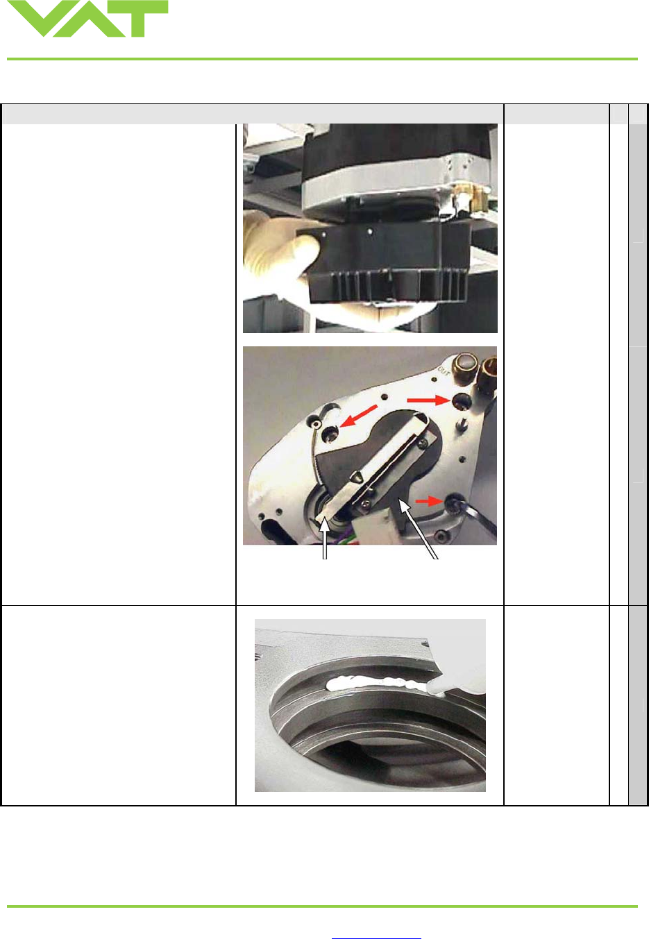
17. Turn off the VAT controller. Wait for
60s, then disconnect cable and
compressed air from valve actuator.
18. Unfasten all 4 motor driver screws
and lift motor driver carefully from
actuator.
Then separate actuator from motor
driver by disconnecting the cable
carefully.
Allen Wrench
3 mm
19. Turn the cog wheel manually to the
middle position.
Caution: Push the cog wheel, not
the position indicator finger.
20. Unfasten all 3 actuator screws and
remove actuator.
position indicator cog wheel
finger
Allen Wrench
5 mm
21. Remove seals from actuator feed
through carefully with a soft tool.
22. Clean actuator feed through with
alcohol.
23. Lubricate each o-ring groove with
0.1 ml vacuum grease. Pay attention
that grease is distributed constantly
over the whole circumference.
Installation, Operating & Maintenance Instructions
Series 650, DN 63-250 (I.D. 2.5"-10")
VAT Vakuumventile AG, CH-9469 Haag, Switzerland
Tel +41 81 771 61 61 Fax +41 81 771 48 30 CH@vatvalve.com www.vatvalve.com 235015EI
2010-01-11 14/20
D e s c r i p t i o n Required tool
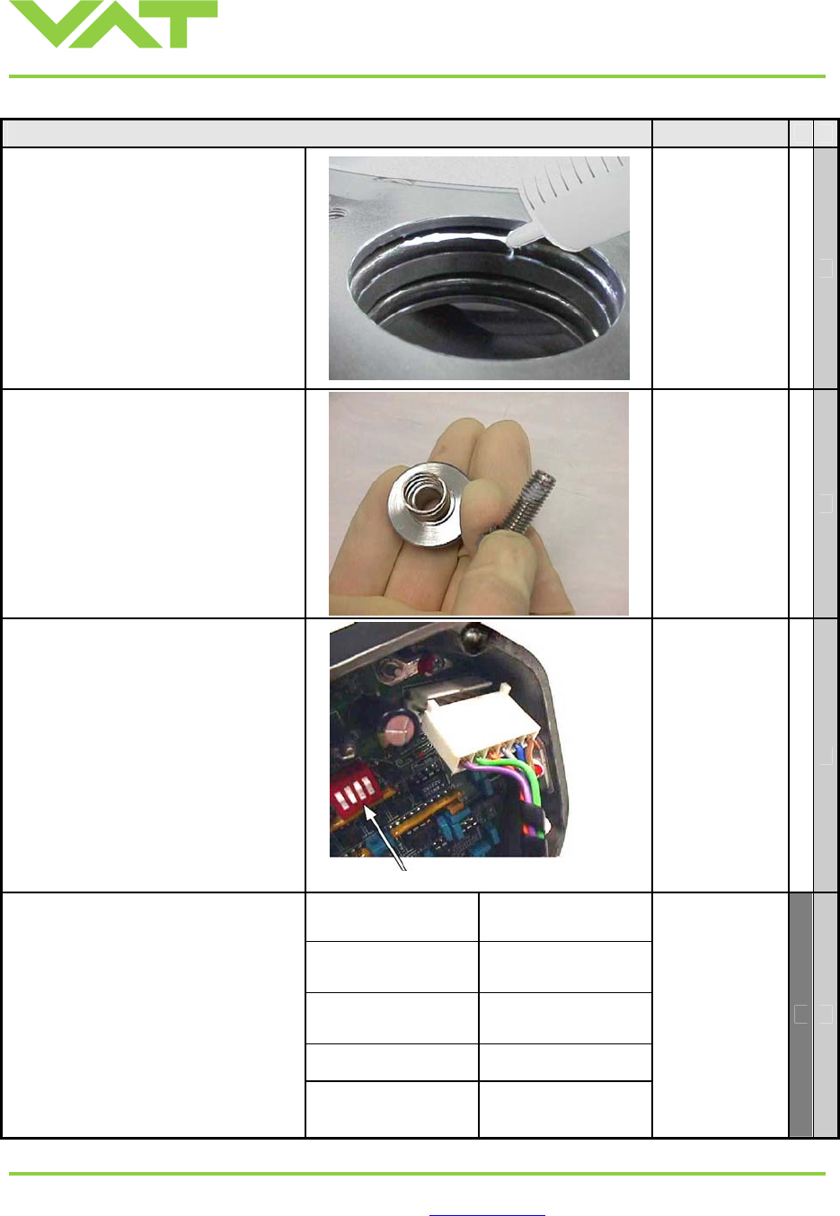
24. Clean or replace seals if necessary.
Lubricate each o-ring with 0.05 ml
vacuum grease.
25. Install o-rings.
26. Deposit 0.1 ml vacuum grease on
each o-ring. Pay attention that
grease is distributed constantly over
the whole circumference.
27. Remove fixation kit and mounting
screw for pendulum plate.
28. Clean screw and slightly lubricate
thread. Then reinstall fixation kit.
29. Clean actuator shaft and lubricate it
with 0.1 ml vacuum grease.
30. Install actuator and motor driver in
reverse order as they had been
disassembled (steps 20 to 17).
• Tighten actuator screws with 6 Nm.
• Remove vacuum grease from
actuator shaft face after
installation.
• Check micro switch configuration of
motor driver (refer to Appendix A –
Micro switch configuration of motor
driver) and make sure that cable
between actuator and motor driver
is connected correctly.
• Tighten motor driver screws with
3 Nm.
micro switch
Allen Wrench
3 mm
and
Allen Wrench
5mm
Valve size Max. torque
[Nm]
DN63 / 2.5” (100 / 4“)
(65036(40) - . . 52 - . . . . )
6
DN160 / 6“
(65044 - . . 52 - . . . . ) 6
DN200 / 8“
(65046 - . . 52 - . . . . ) 6
31. Install sealing ring and pendulum
plate in reverse order as they had
been disassembled (steps 9 to 5).
32. Mount valve bonnet.
• Tightening torques for bonnet
screws are listed in the table to the
right.
DN250 / 10“
(65048 - . . 52 - . . . . ) 6
Allen wrench
5mm
and
open end wrench
13mm
Installation, Operating & Maintenance Instructions
Series 650, DN 63-250 (I.D. 2.5"-10")
VAT Vakuumventile AG, CH-9469 Haag, Switzerland
Tel +41 81 771 61 61 Fax +41 81 771 48 30 CH@vatvalve.com www.vatvalve.com 235015EI
2010-01-11 15/20
5 Drawing
Installation, Operating & Maintenance Instructions
Series 650, DN 63-250 (I.D. 2.5"-10")
VAT Vakuumventile AG, CH-9469 Haag, Switzerland
Tel +41 81 771 61 61 Fax +41 81 771 48 30 CH@vatvalve.com www.vatvalve.com 235015EI
2010-01-11 16/20
6 Spare parts
Please specify the fabrication number of the valve (see yellow label on valve) when ordering spare parts. This is
to ensure that the appropriate spare parts are supplied.
Item Description
Valve size
Valve part number
DN63 / 2.5” (100 / 4“)
(65036(40) - . . 52 - . . . . )
DN160
65044 - . . 52 - . . . .
DN200
65046- . . 52 - . . . .
DN250
65048 - . . 52 - . . . .
Viton N-5100-259 N-5100-267 N-5100-272 N-5100-277 1 Bonnet
seal other materials on request on request on request on request
2 Body seal (Viton)
This includes a 2ml syringe of
vacuum grease
204884 206527 200468 202592
Viton N-5100-155 N-5100-258 N-5100-266 N-5100-275
3 Gate
seal other materials on request on request on request on request
Seal kit vacuum (Viton).
This consists of item 2 and 3. 204883 206526 204204 203883
2ml 206792 Syringe of vacuum
grease 5ml 206793
4 Actuator shaft seals (Viton) N-5111-329
(2 pcs required per valve)
5
Sealing ring shaft seals (Viton) N-5111-112
(12 pcs required per valve)
N-5111-112
(8 pcs required per
valve)
N-5111-112
(12 pcs required per
valve)
N-5111-112
(16 pcs required per
valve)
Pendulum plate:
- Blank B1 *) 91048-01 101570-01 201272 94632-01
- Blank B2 *) on request 231343 226661 on request
- Hardanodized B1 *) 100741-01 98371-01 200500 92228-01
- Hardanodized B2 *) 226810 98673-01 201437 92229-01
- Nickel coated B1 *) 91048-01 on request 211613 on request
- Nickel coated B2 *) on request on request on request on request
- Stainless steel B1 *) on request on request 205296 not available
6
- Stainless steel B2 *) on request on request on request not available
Sealing ring
- Blank 216490 207518 204453 205874
- Hardanodized 217050 204340 202046 203217
- Nickel coated 241368 on request 211610 on request
7
- Stainless steel on request on request 205417 not available
B1 *) 235154
8 Actuator complete
(incl. motor driver) B2 *) 235155
Aluminum 32040-QAZV 32044-QAZV 32046-QAZV 32048-QAZV
ISO-F
centering ring
with Viton o-ring
for installation Stainless
steel 32040-QEZV 32044-QEZV 32046-QEZV 32048-QEZV
The item numbers refer to the drawing on page 15
Note: Use only spare parts manufactured by VAT to assure safe and reliable operation!
*) Refer to figures on next page to check for actuator position options.
Installation, Operating & Maintenance Instructions
Series 650, DN 63-250 (I.D. 2.5"-10")
VAT Vakuumventile AG, CH-9469 Haag, Switzerland
Tel +41 81 771 61 61 Fax +41 81 771 48 30 CH@vatvalve.com www.vatvalve.com 235015EI
2010-01-11 17/20
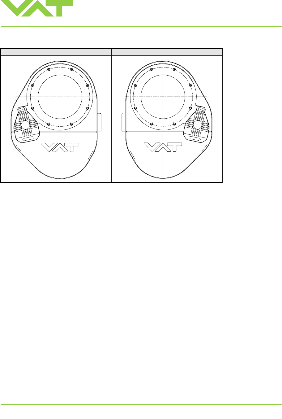
Actuator position options:
Valve with B1 actuator (standard) Valve with B2 actuator (option)
Installation, Operating & Maintenance Instructions
Series 650, DN 63-250 (I.D. 2.5"-10")
VAT Vakuumventile AG, CH-9469 Haag, Switzerland
Tel +41 81 771 61 61 Fax +41 81 771 48 30 CH@vatvalve.com www.vatvalve.com 235015EI
2010-01-11 18/20
7 Trouble shooting
Failure Check Action
VAT connection cable (controller to
valve) connected correctly? Connect cable to controller and valve
Power for VAT controller supplied? Connect VAT controller to power supply or
mains respectively. Check if mains switch is
on if present. For details refer to manual of
VAT controller.
Valve does not
close/open/control
Compressed air pressure supplied for
valve? Connect compressed air to valve. Refer to
«2.2 Installation procedure» for details.
Setup of VAT controller done
correctly? Refer to manual of VAT controller for details.
Correct operation mode selected? Refer to manual of VAT controller for details.
Pressure / position control
does not work
Pressure gauge installed, setup
correct and connected to VAT
controller?
Refer to manual of pressure gauge and VAT
controller for details.
Sealing area contaminated? Clean pendulum plate and sealing ring.
Sealing surfaces of pendulum plate
or/and sealing ring damaged? Replace damaged part. Refer to «4.1
Preventive maintenance procedures».
Sealing surfaces on valve body
damaged? Please contact your VAT service center for
repair.
Leak at gate
O-rings on sealing ring damaged or
not installed correctly? Install o-ring correctly. Replace it if
necessary. Refer to «4.1 Preventive
maintenance procedures».
Flanges leaktight? Sealing surface or
flange seal damaged? Verify if valve is installed correctly according
to «2.2.1 Install valve into system» and
admissible forces are not exceeded. Replace
o-ring if necessary. Please contact a VAT
service center for repair if flange sealing
surface of valve is damaged.
Valve bonnet leaktight? Verify if bonnet screws are tightened with
correct torque (see page 14). Replace
bonnet seal if necessary.
Actuator feedthroughs leaktight? Perform His leak check at intermediate
pumping port of actuator (see Figure 2 on
page 7). Replace seals according to «4.1
Preventive maintenance procedures» if
necessary.
Leak to outside
Leak at sealing ring shaft seals of
retaining pins. Please contact a VAT service center for
repair.
If you need any further information, please contact one of our service centers. You can find the addresses on our website:
http://www.vat.ch

Installation, Operating & Maintenance Instructions
Series 650, DN 63-250 (I.D. 2.5"-10")
VAT Vakuumventile AG, CH-9469 Haag, Switzerland
Tel +41 81 771 61 61 Fax +41 81 771 48 30 CH@vatvalve.com www.vatvalve.com 235015EI
2010-01-11 19/20
8 Warranty
Each product sold by VAT Vakuumventile AG (VAT) is warranted to be free from the manufacturing defects that adversely
affect the normal functioning thereof during the warranty period stated in VAT's «Terms of Sale» immediately following
delivery thereof by VAT, provided that the same is properly operated under conditions of normal use and that regular,
periodic maintenance and service is performed or replacements made, in accordance with the instructions provided by
VAT. The foregoing warranty shall not apply to any product or component that has been repaired or altered by anyone
other than an authorized VAT representative or that has been subject to improper installation or abuse, misuse,
negligence or accident. VAT shall not be liable for any damage, loss, or expense, whether consequential, special,
incidental, direct or otherwise, caused by, arising out of or connected with the manufacture, delivery (including any delay
in or failure to deliver), packaging, storage or use of any product sold or delivered by VAT shall fail to conform to the
foregoing warranty or to the description thereof contained herein, the purchaser thereof, as its exclusive remedy, shall
upon prompt notice to VAT of any such defect or failure and upon the return of the product, part or component in question
to VAT at its factory, with transportation charges prepaid, and upon VAT's inspection confirming the existence of any
defect inconsistent with said warranty or any such failure, be entitled to have such defect or failure cured at VAT's factory
and at no charge therefor, by replacement or repair of said product, as VAT may elect. VAT MAKES NO WARRANTY OR
REPRESENTATION OF ANY KIND, EXPRESS OR IMPLIED, (INCLUDING NO WARRANTY OR MERCHANTABILITY),
EXCEPT FOR THE FOREGOING WARRANTY AND THE WARRANTY THAT EACH PRODUCT SHALL CONFORM TO
THE DESCRIPTION THEREOF CONTAINED HEREIN, and no warranty shall be implied by law.
Furthermore, the «Terms of sale» at the back of the price list are applicable.
Installation, Operating & Maintenance Instructions
Series 650, DN 63-250 (I.D. 2.5"-10")
VAT Vakuumventile AG, CH-9469 Haag, Switzerland
Tel +41 81 771 61 61 Fax +41 81 771 48 30 CH@vatvalve.com www.vatvalve.com 235015EI
2010-01-11 20/20
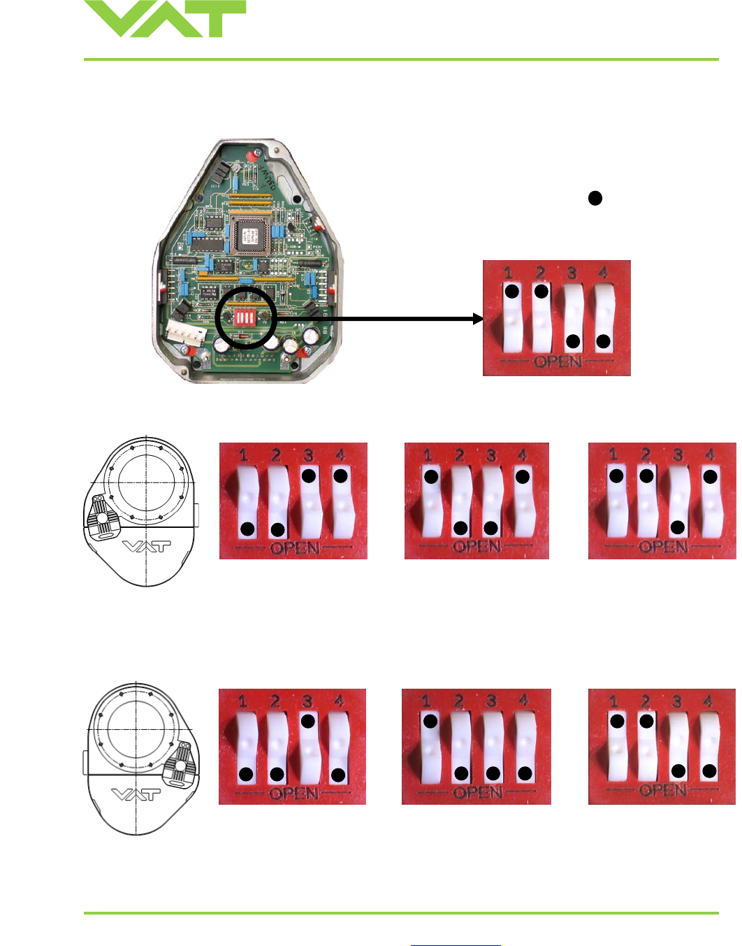
9 Appendix A – Micro switch configuration of motor driver
9.1 For valves with actuator position B1
9.2 For valves with actuator position B2
Switch position for:
• DN250
Switch position for:
• DN160
• DN200
Switch position for:
• DN63
• DN100
Switch position for:
• DN250
Switch position for:
• DN160
• DN200
Switch position for:
• DN63
• DN100
Micro switch S1
(example)
The black point ( ) means:
«Push down»
