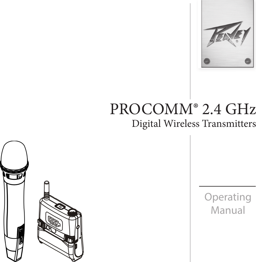
Peavey Electronics PCXDBP Transmitter User Manual
Peavey Electronics Corporation Transmitter Users Manual
UserManual.wiki
>
Peavey Electronics
>
PCXDBP User Manual
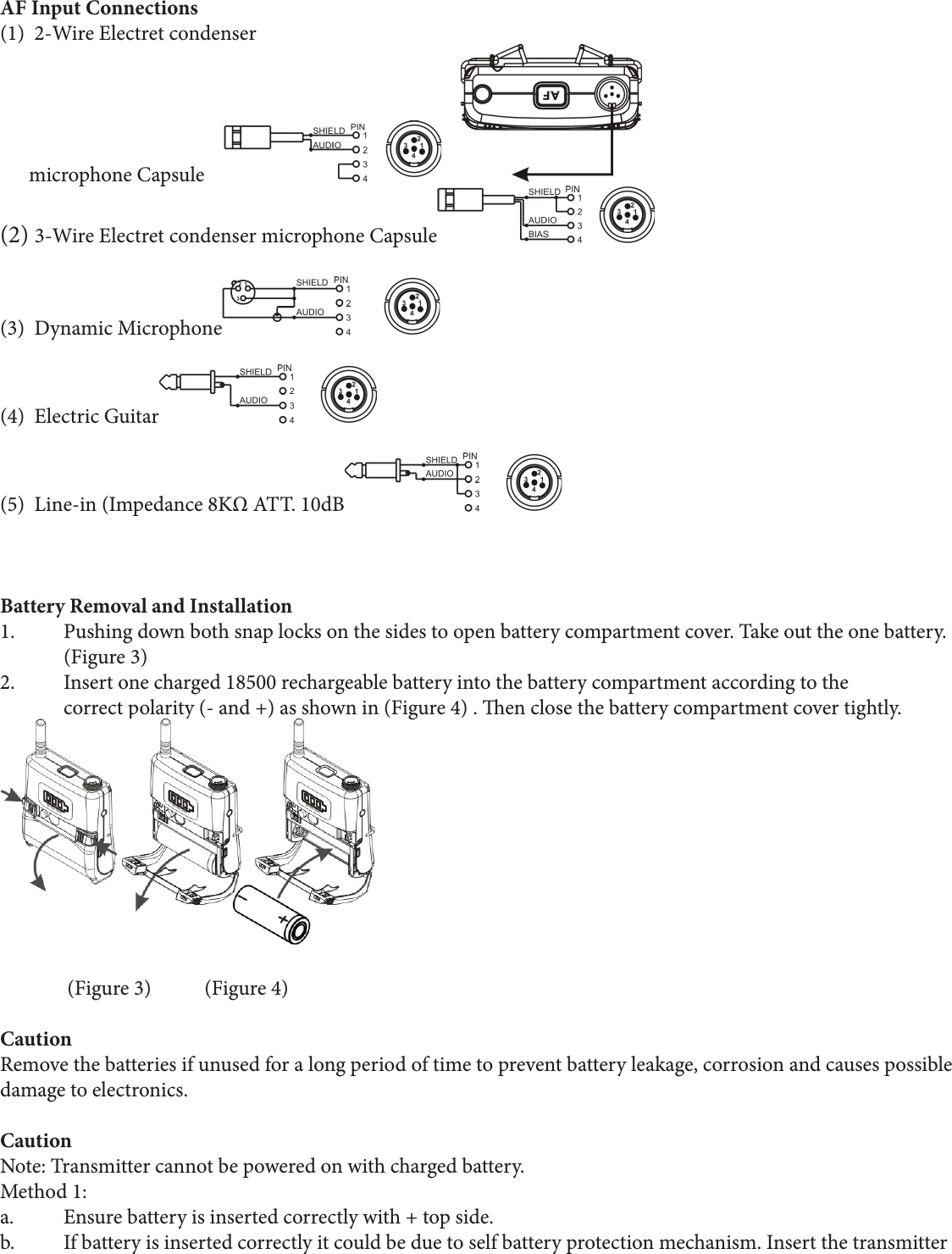
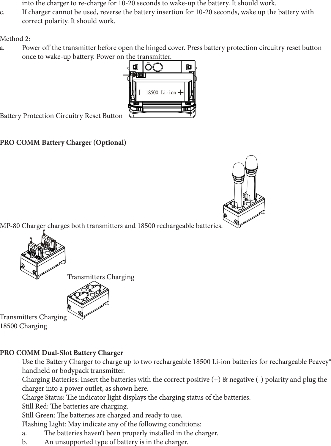
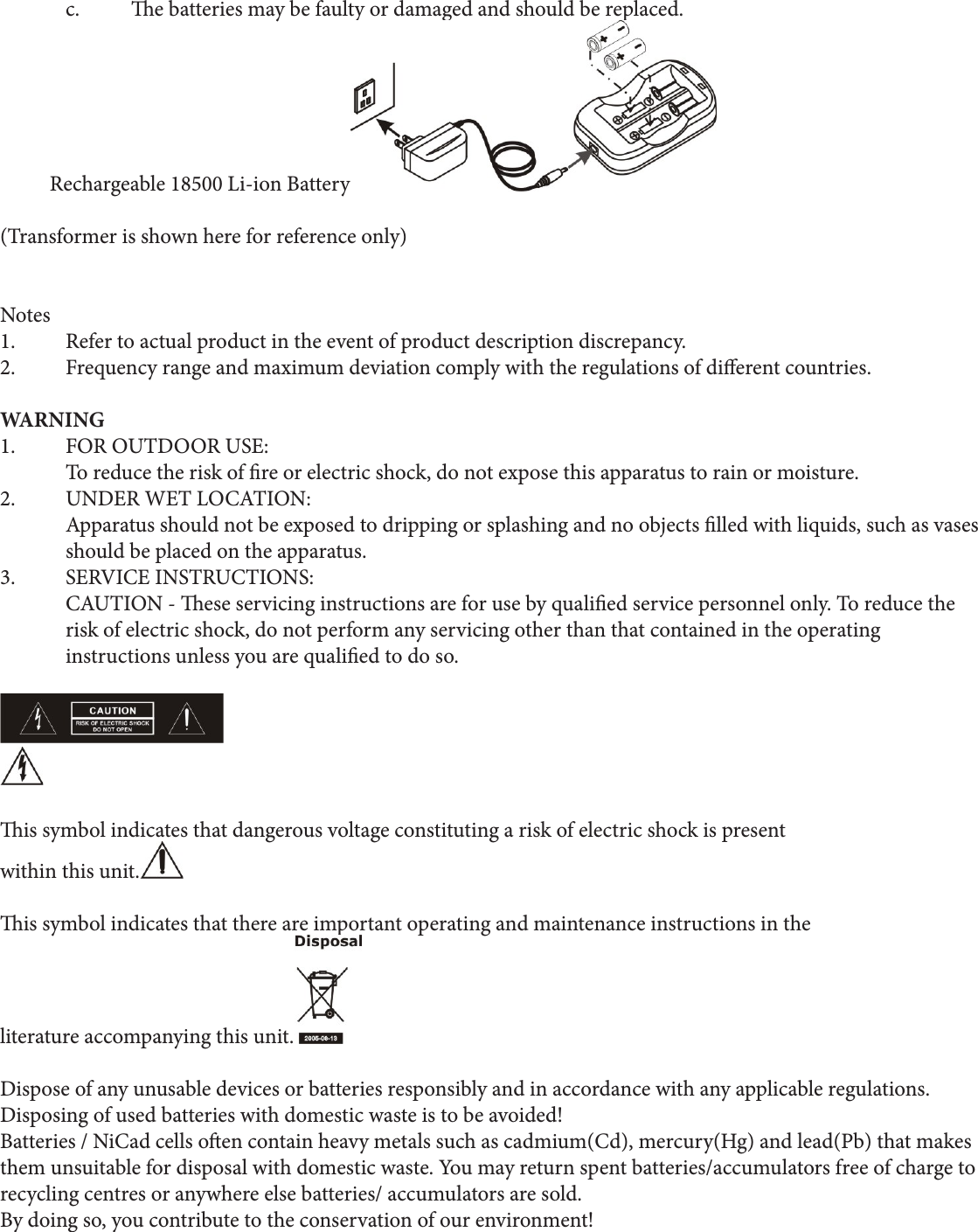
Users Manual
Navigation menu
Upload a User Manual
Namespaces
Wiki Guide
HTML
PDF
Info
Views
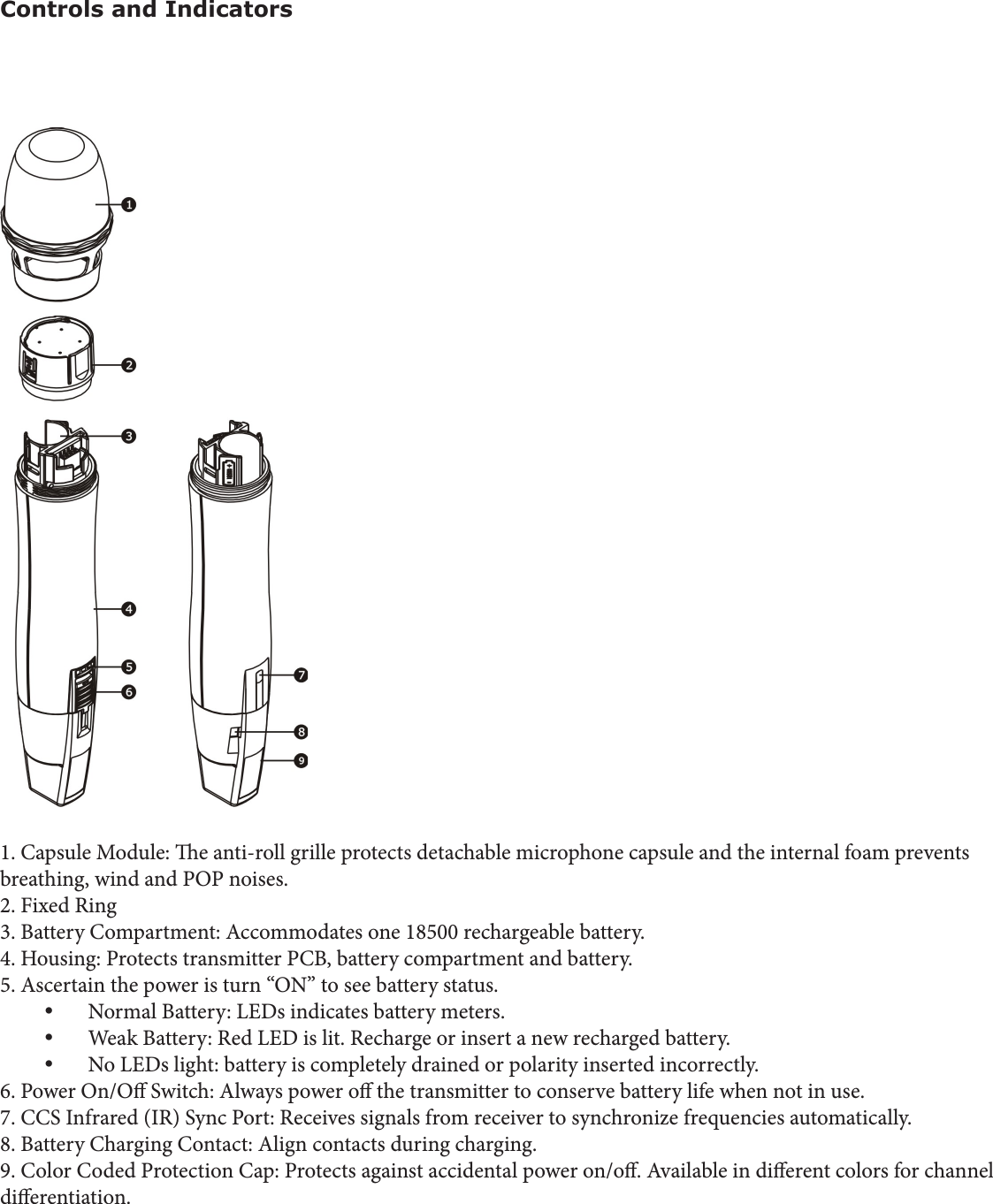
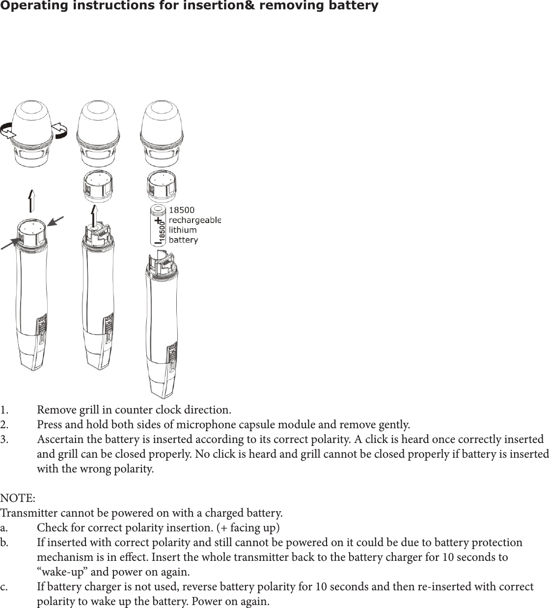
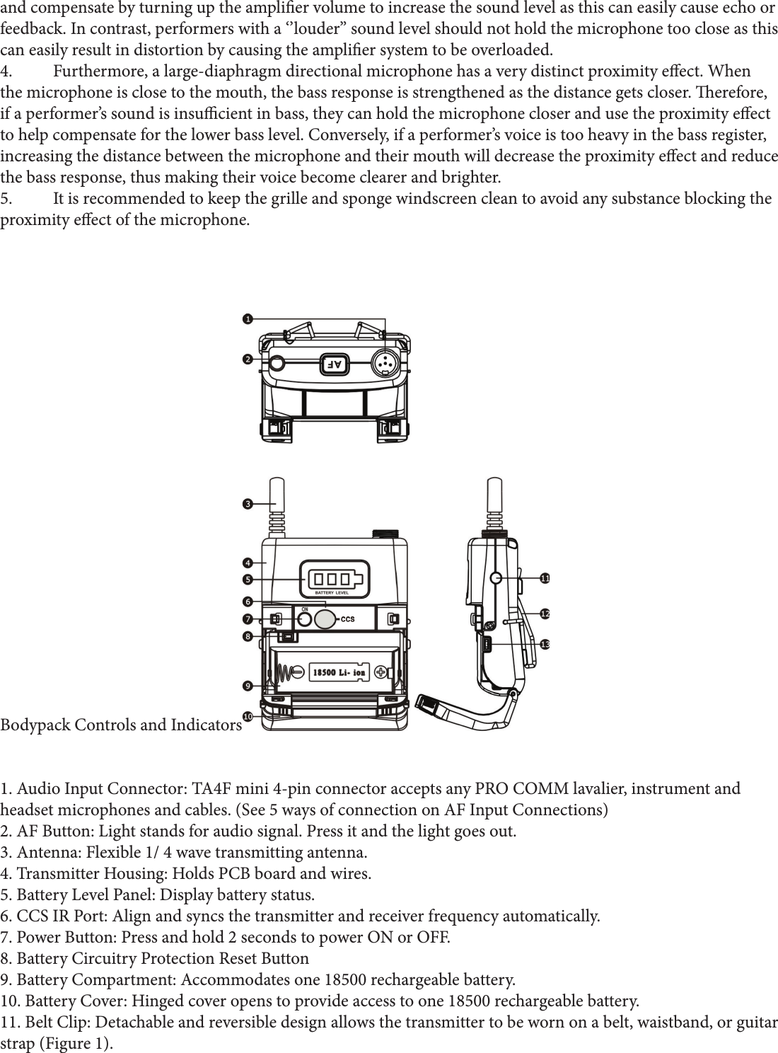
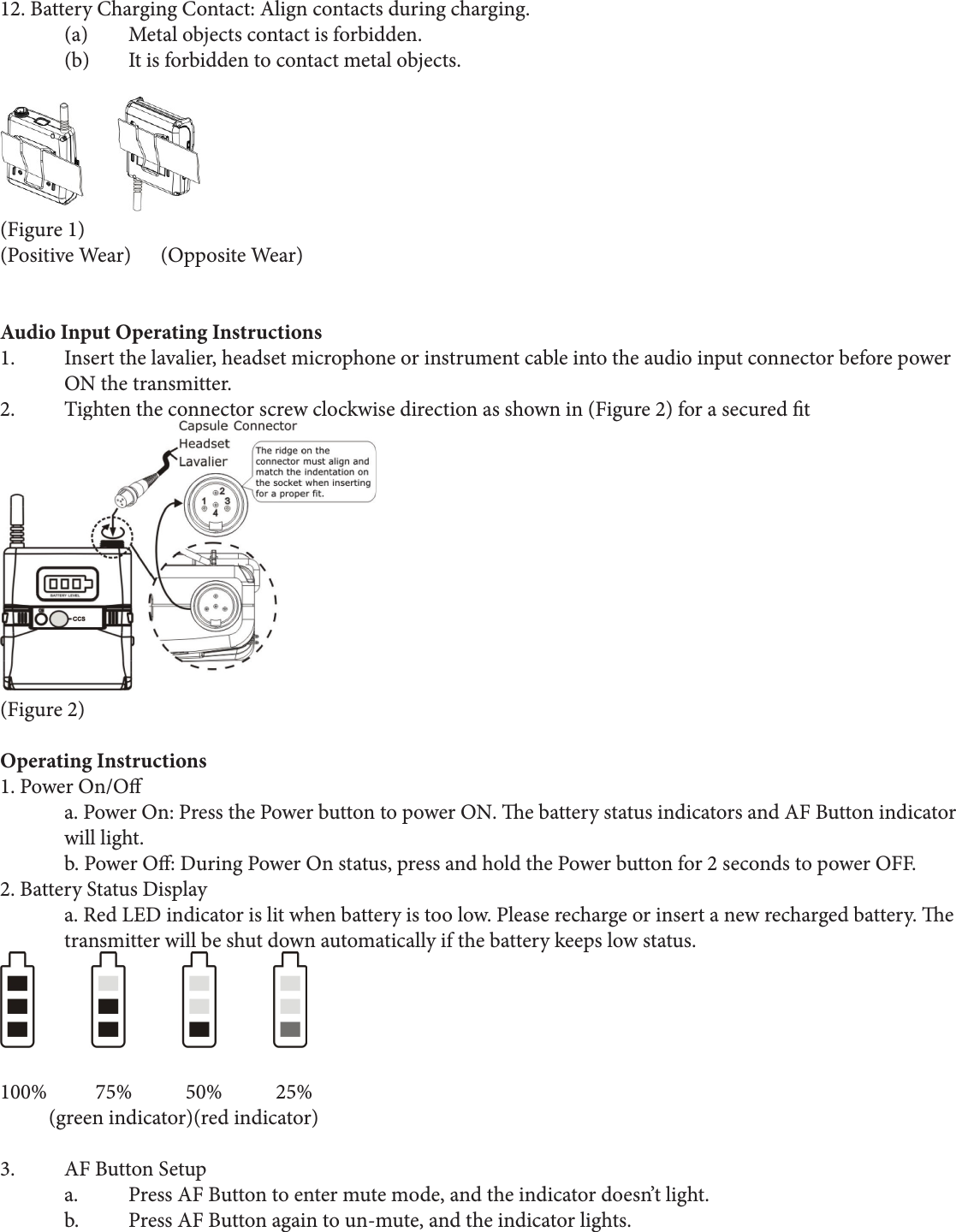
User Manual
Discussion / Help
Navigation