Peavey Electronics PCXDBP Transmitter User Manual
Peavey Electronics Corporation Transmitter Users Manual
Users Manual
www.peavey.com
PROCOMM® 2.4 GHz
Digital Wireless Transmitters
Operating
Manual

FCC/ICESCompliancyStatement
FCCID:I4S-PCXDBP
FCCID:I4S-PCXDHT
ThisdevicecomplieswithPart15oftheFCCrulesandIndustryCanadalicense-exemptRSSStandard(s).Operationis
subjecttothefollowingtwoconditions:(1)thisdevicemaynotcauseharmfulinterference,and(2)thisdevicemust
acceptanyinterferencereceived,thatmaycauseundesiredoperation.
LeprésentappareilestconformeauxCNRd’lndustrieCanadaapplicablesauxappareilsradioexemptsde
licence.L’exploitationestautoriséeauxdeuxconditionssuivantes:(1)I’appareilnedoitpasproduirede
brouillage,et(2)I’utilisateurdeI’appareildoitacceptertoutbrouillageradioélectriquesubi,mêmesile
brouillageestsusceptibled’encompromettrelefonctionnement.
Caution:ChangesormodificationstotheequipmentnotapprovedbyPeaveyElectronicsCorp.canvoidthe
user’sauthoritytousetheequipment.
Note–ThisequipmenthasbeentestedandfoundtocomplywiththelimitsforaClassBdigitaldevice,
pursuanttoPart15oftheFCCRules.Theselimitsaredesignedtoprovidereasonableprotectionagainst
harmfulinterferenceinaresidentialinstallation.Thisequipmentgenerates,uses,andcanradiateradio
frequencyenergyand,ifnotinstalledandusedinaccordancewiththeinstructions,maycauseharmful
interferencetoradiocommunications.However,thereisnoguaranteethatinterferencewillnotoccurina
particularinstallation.Ifthisequipmentdoescauseharmfulinterferencetoradioortelevisionreception,
whichcanbedeterminedbyturningtheequipmentoffandon,theuserisencouragedtotryandcorrectthe
interferencebyoneormoreofthefollowingmeasures.
Reorient or relocate the receiving antenna.
Increase the separation between the equipment and receiver.
Connect the equipment into an outlet on a circuit different from that to which the receiver is
connected.
Consult the dealer or an experienced radio/TV technician for help.
Radiation Exposure Statement
The equipment complies with FCC RF radiation exposure limits set forth for an
uncontrolled environment.
Prudence:Lesmodificationsapportées àl'équipementnonapprouvésparPeaveyElectronicsCorp.
peuventannulerledroitdel'utilisateuràutiliserl'équipement.
IC:3642A-PCXDBP
IC:3642A-PCXDHT
L'exposition aux radiations
L'équipement est conforme aux limites d'exposition aux radiations d'Industrie
Canada définies pour un environnement non contrôlé.
FCC Radiation Exposure Statement(for Model number: PCX-D HT)
This equipment complies with FCC &IC RSS-102 RF radiation exposure limits set forth for an uncontrolled
environment. This equipment should be installed and operated with a minimum distance of 1.5 centimeters
between the radiator and your body.
is transmitter must not be co-located or operating in conjunction with any other antenna or transmitter.
The antennas used for this transmitter must be installed to provide a separation distance of at least 1.5 cm
from all persons and must not be co-located or operating in conjunction with any other antenna or
transmitter.
Déclaration d’exposition à la radiation:
Cet équipement respecte les limites d’exposition aux rayonnements IC RSS-102 dénies pour un environnement
non contrôlé. Cet équipement doit être installé et mis en marche à une distance minimale de 1.5 cm qui sépare
l’élément rayonnant de votre corps.
FCC Radiation Exposure Statement(for Model number: PCX-D BP)
This equipment complies with FCC &IC RSS-102 RF radiation exposure limits set forth for an uncontrolled
environment. This equipment should be installed and operated with a minimum distance of 1 centimeters
between the radiator and your body.
This transmitter must not be co-located or operating in conjunction with any other antenna or transmitter.
The antennas used for this transmitter must be installed to provide a separation distance of at least 1 cm from
all persons and must not be co-located or operating in conjunction with any other antenna or transmitter.
Déclaration d’exposition à la radiation:
Cet équipement respecte les limites d’exposition aux rayonnements IC RSS-102 dénies pour un environnement
non contrôlé. Cet équipement doit être installé et mis en marche à une distance minimale de 1 cm qui sépare
l’élément rayonnant de votre corps.
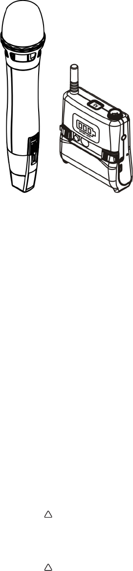
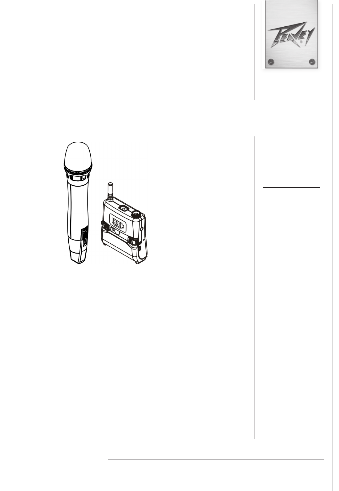
PRO COMM® 2.4 GHz Digital Wireless System
PRO COMM Rechargeable Handheld Transmitter
PRO COMM Rechargeable Bodypack Transmitter
Contains lithium ion batteries. Lithium
ion batteries contain Perchlorate-special
handling may apply.
See www.dtsc.ca.gov/hazardouswaste/perchlorate
WARNING:
!
Lithium Ion batteries may be a re hazard.
Do not expose to open ame or excessive heat.
WARNING:
!
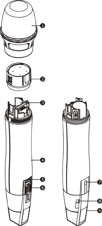
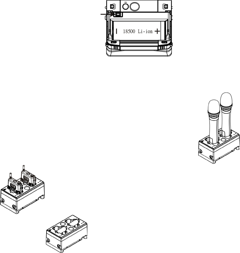
Controls and Indicators
1. Capsule Module: e anti-roll grille protects detachable microphone capsule and the internal foam prevents
breathing, wind and POP noises.
2. Fixed Ring
3. Battery Compartment: Accommodates one 18500 rechargeable battery.
4. Housing: Protects transmitter PCB, battery compartment and battery.
5. Ascertain the power is turn “ON” to see battery status.
Normal Battery: LEDs indicates battery meters.
Weak Battery: Red LED is lit. Recharge or insert a new recharged battery.
No LEDs light: battery is completely drained or polarity inserted incorrectly.
6. Power On/O Switch: Always power o the transmitter to conserve battery life when not in use.
7. CCS Infrared (IR) Sync Port: Receives signals from receiver to synchronize frequencies automatically.
8. Battery Charging Contact: Align contacts during charging.
9. Color Coded Protection Cap: Protects against accidental power on/o. Available in dierent colors for channel
dierentiation.
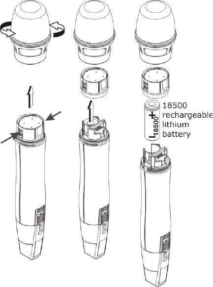
Operating instructions for insertion& removing battery
1. Remove grill in counter clock direction.
2. Press and hold both sides of microphone capsule module and remove gently.
3. Ascertain the battery is inserted according to its correct polarity. A click is heard once correctly inserted
and grill can be closed properly. No click is heard and grill cannot be closed properly if battery is inserted
with the wrong polarity.
NOTE:
Transmitter cannot be powered on with a charged battery.
a. Check for correct polarity insertion. (+ facing up)
b. If inserted with correct polarity and still cannot be powered on it could be due to battery protection
mechanism is in eect. Insert the whole transmitter back to the battery charger for 10 seconds to
“wake-up” and power on again.
c. If battery charger is not used, reverse battery polarity for 10 seconds and then re-inserted with correct
polarity to wake up the battery. Power on again.
Operating Instructions
1. Power On & O
a. Power On: Push the ON/OFF switch to the “ON” location, the battery indicators will light.
b. Power O: Push the ON/OFF switch back, the battery indicators will go out.
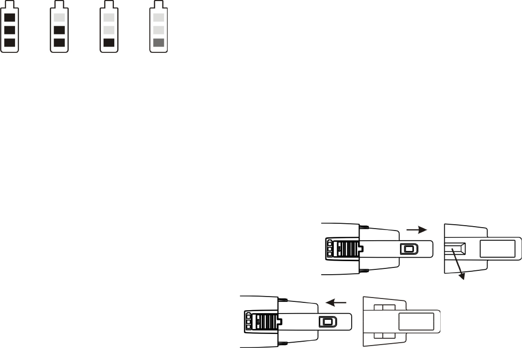
2. Battery Status Display
a. Red LED indicator is lit when battery is too low. Please recharge or insert a new recharged battery. e
microphone will be shut down automatically if the battery keeps low status
100% 75% 50% 25%
(green indicator)(red indicator)
Rear Cap has an On/O Switch Protection
e patented color rear cap serves two purposes; it provides easy channel identication and protects the on/
o switch. It is designed to allow the on/o switch to either be exposed or concealed as desired. You can avoid
unintended switching o of the microphone by rotating the color rear cap 180 degrees to x the on/o switch.
e cap can be removed by gripping it rmly and pulling; be sure to push it rmly into place when replacing it
on the microphone.
Note: During microphone usage, the color rear cap must be installed.
Press both sides and pull out to remove the rear cap
Turn the rear cap 180 degree and insert back
e ON/OFF switch is immovable
General Tips for Improving System Performance
1. Performer should avoid holding the microphone over or near the antenna section as this will deteriorate
transmission eciency. Severe deterioration if performer directly covers up the antenna section with both hands.
2. Many performers tend to hold the microphone by the top grille. Unfortunately, this position seriously
degrades both the sound quality and directionality of a microphone. Even the most expensive microphones will
have its original sound quality compromised by this method. Grabbing a microphone by the grille will isolate
the capsule’s acoustic resonance circuit or change the capsule resonator’s frequency. is results in an inferior
performance in both frequency response and the separation of directionality. In addition, a palm’s sound-
focusing eect will tend to strengthen resonances in certain frequencies and can cause unwanted echo.
3. A proper technique is required for using directional microphones because the distance between the
microphone and your mouth has a signicant impact on sensitivity and performance. ere is an inverse
relationship between microphone sensitivity and the distance from the mouth to the microphone. Consequently,
performers with a ‘’weaker’’ sound level cannot expect to hold the microphone too far away from their mouth
and compensate by turning up the amplier volume to increase the sound level as this can easily cause echo or
feedback. In contrast, performers with a ‘’louder’’ sound level should not hold the microphone too close as this
can easily result in distortion by causing the amplier system to be overloaded.
4. Furthermore, a large-diaphragm directional microphone has a very distinct proximity eect. When
the microphone is close to the mouth, the bass response is strengthened as the distance gets closer. erefore,
if a performer’s sound is insucient in bass, they can hold the microphone closer and use the proximity eect
to help compensate for the lower bass level. Conversely, if a performer’s voice is too heavy in the bass register,
increasing the distance between the microphone and their mouth will decrease the proximity eect and reduce
the bass response, thus making their voice become clearer and brighter.
5. It is recommended to keep the grille and sponge windscreen clean to avoid any substance blocking the
proximity eect of the microphone.
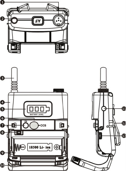
Bodypack Controls and Indicators
1. Audio Input Connector: TA4F mini 4-pin connector accepts any PRO COMM lavalier, instrument and
headset microphones and cables. (See 5 ways of connection on AF Input Connections)
2. AF Button: Light stands for audio signal. Press it and the light goes out.
3. Antenna: Flexible 1/ 4 wave transmitting antenna.
4. Transmitter Housing: Holds PCB board and wires.
5. Battery Level Panel: Display battery status.
6. CCS IR Port: Align and syncs the transmitter and receiver frequency automatically.
7. Power Button: Press and hold 2 seconds to power ON or OFF.
8. Battery Circuitry Protection Reset Button
9. Battery Compartment: Accommodates one 18500 rechargeable battery.
10. Battery Cover: Hinged cover opens to provide access to one 18500 rechargeable battery.
11. Belt Clip: Detachable and reversible design allows the transmitter to be worn on a belt, waistband, or guitar
strap (Figure 1).
12. Battery Charging Contact: Align contacts during charging.
(a) Metal objects contact is forbidden.
(b) It is forbidden to contact metal objects.
(Figure 1)
(Positive Wear) (Opposite Wear)
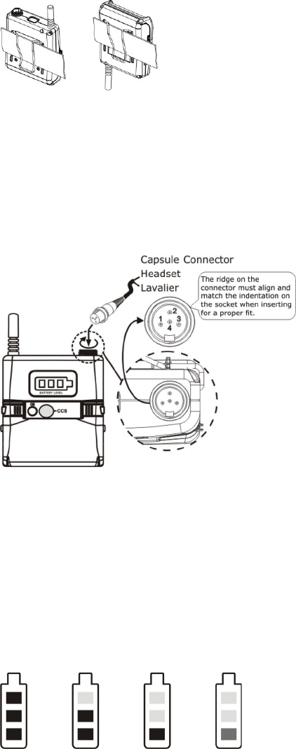
Audio Input Operating Instructions
1. Insert the lavalier, headset microphone or instrument cable into the audio input connector before power
ON the transmitter.
2. Tighten the connector screw clockwise direction as shown in (Figure 2) for a secured t
(Figure 2)
Operating Instructions
1. Power On/O
a. Power On: Press the Power button to power ON. e battery status indicators and AF Button indicator
will light.
b. Power O: During Power On status, press and hold the Power button for 2 seconds to power OFF.
2. Battery Status Display
a. Red LED indicator is lit when battery is too low. Please recharge or insert a new recharged battery. e
transmitter will be shut down automatically if the battery keeps low status.
100% 75% 50% 25%
(green indicator)(red indicator)
3. AF Button Setup
a. Press AF Button to enter mute mode, and the indicator doesn’t light.
b. Press AF Button again to un-mute, and the indicator lights.
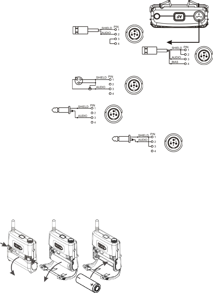
AF Input Connections
(1) 2-Wire Electret condenser
microphone Capsule
(2) 3-Wire Electret condenser microphone Capsule
(3) Dynamic Microphone
(4) Electric Guitar
(5) Line-in (Impedance 8KΩ ATT. 10dB
Battery Removal and Installation
1. Pushing down both snap locks on the sides to open battery compartment cover. Take out the one battery.
(Figure 3)
2. Insert one charged 18500 rechargeable battery into the battery compartment according to the
correct polarity (- and +) as shown in (Figure 4) . en close the battery compartment cover tightly.
(Figure 3) (Figure 4)
Caution
Remove the batteries if unused for a long period of time to prevent battery leakage, corrosion and causes possible
damage to electronics.
Caution
Note: Transmitter cannot be powered on with charged battery.
Method 1:
a. Ensure battery is inserted correctly with + top side.
b. If battery is inserted correctly it could be due to self battery protection mechanism. Insert the transmitter
into the charger to re-charge for 10-20 seconds to wake-up the battery. It should work.
c. If charger cannot be used, reverse the battery insertion for 10-20 seconds, wake up the battery with
correct polarity. It should work.
Method 2:
a. Power o the transmitter before open the hinged cover. Press battery protection circuitry reset button
once to wake-up battery. Power on the transmitter.
Battery Protection Circuitry Reset Button
PRO COMM Battery Charger (Optional)
MP-80 Charger charges both transmitters and 18500 rechargeable batteries.
Transmitters Charging
Transmitters Charging
18500 Charging
PRO COMM Dual-Slot Battery Charger
Use the Battery Charger to charge up to two rechargeable 18500 Li-ion batteries for rechargeable Peavey®
handheld or bodypack transmitter.
Charging Batteries: Insert the batteries with the correct positive (+) & negative (-) polarity and plug the
charger into a power outlet, as shown here.
Charge Status: e indicator light displays the charging status of the batteries.
Still Red: e batteries are charging.
Still Green: e batteries are charged and ready to use.
Flashing Light: May indicate any of the following conditions:
a. e batteries haven’t been properly installed in the charger.
b. An unsupported type of battery is in the charger.
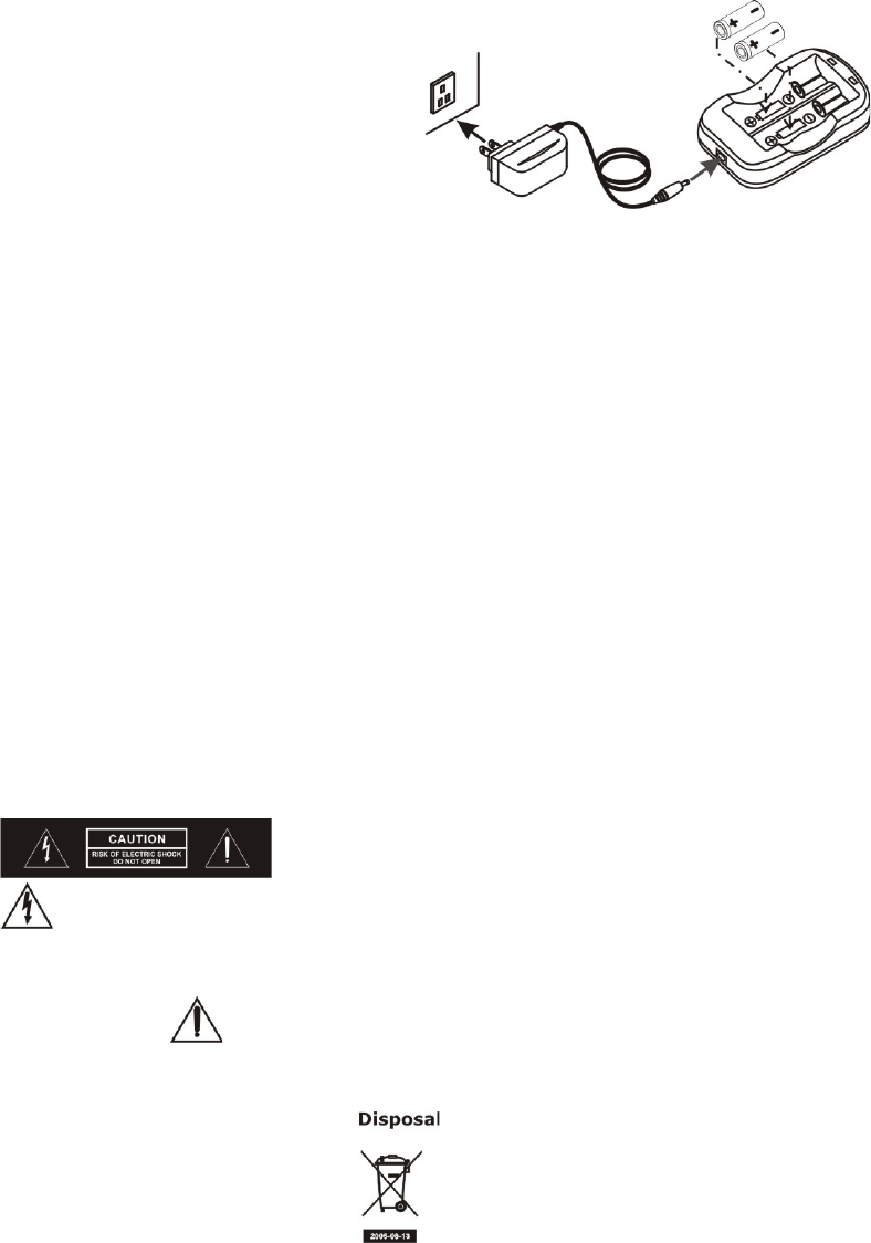
c. e batteries may be faulty or damaged and should be replaced.
Rechargeable 18500 Li-ion Battery
(Transformer is shown here for reference only)
Notes
1. Refer to actual product in the event of product description discrepancy.
2. Frequency range and maximum deviation comply with the regulations of dierent countries.
WARNING
1. FOR OUTDOOR USE:
To reduce the risk of re or electric shock, do not expose this apparatus to rain or moisture.
2. UNDER WET LOCATION:
Apparatus should not be exposed to dripping or splashing and no objects lled with liquids, such as vases
should be placed on the apparatus.
3. SERVICE INSTRUCTIONS:
CAUTION - ese servicing instructions are for use by qualied service personnel only. To reduce the
risk of electric shock, do not perform any servicing other than that contained in the operating
instructions unless you are qualied to do so.
is symbol indicates that dangerous voltage constituting a risk of electric shock is present
within this unit.
is symbol indicates that there are important operating and maintenance instructions in the
literature accompanying this unit.
Dispose of any unusable devices or batteries responsibly and in accordance with any applicable regulations.
Disposing of used batteries with domestic waste is to be avoided!
Batteries / NiCad cells oen contain heavy metals such as cadmium(Cd), mercury(Hg) and lead(Pb) that makes
them unsuitable for disposal with domestic waste. You may return spent batteries/accumulators free of charge to
recycling centres or anywhere else batteries/ accumulators are sold.
By doing so, you contribute to the conservation of our environment!

Logo referenced in Directive 2002/96/EC Annex IV
(OJ(L)37/38,13.02.03 and defined in EN 50419: 2005
The bar is the symbol for marking of new waste and
is applied only to equipment manufactured after
13 August 2005
www.peavey.com
Warranty registration and information for U.S. customers available online at
www.peavey.com/warranty
or use the QR tag below
Features and specications subject to change without notice.
Peavey Electronics Corporation 5022 Hartley Peavey Drive Meridian, MS 39305 (601) 483-5365 FAX (601) 486-1278