Pektron Group 005 Karma Automotive Key Fob User Manual Karma User Handbook
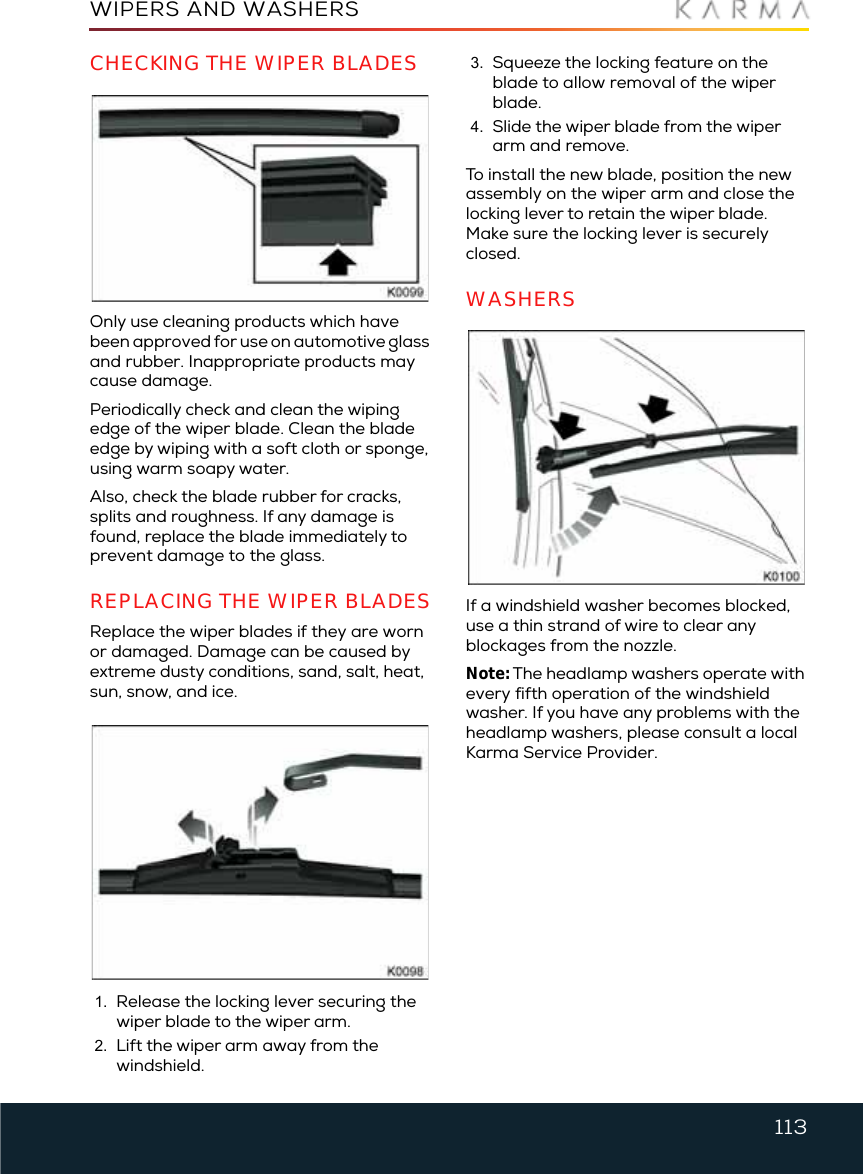
Pektron Group Ltd Karma Automotive Key Fob Karma User Handbook
UserManual.wiki
>
Pektron Group
>
005 User Manual
User Manual
Navigation menu
Upload a User Manual
Namespaces
Wiki Guide
HTML
PDF
Info
Views
User Manual
Discussion / Help
Navigation


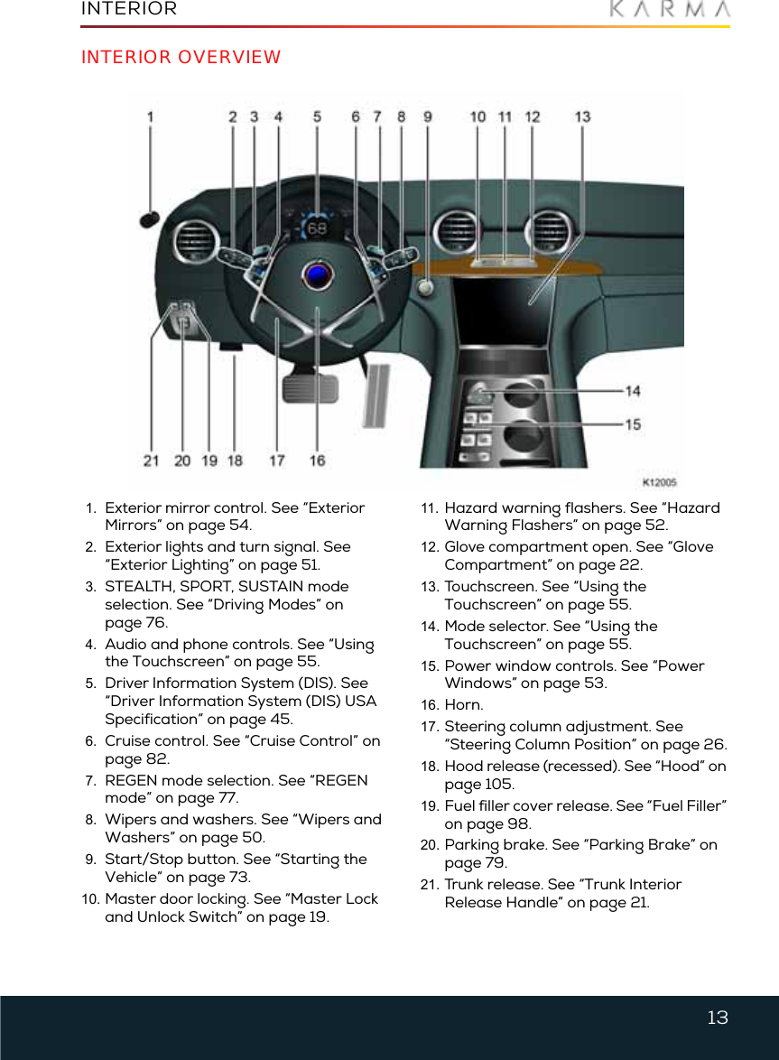
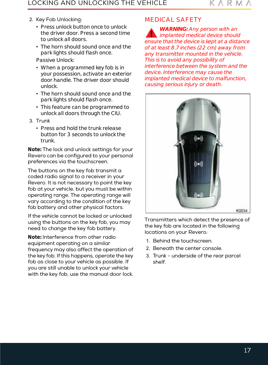
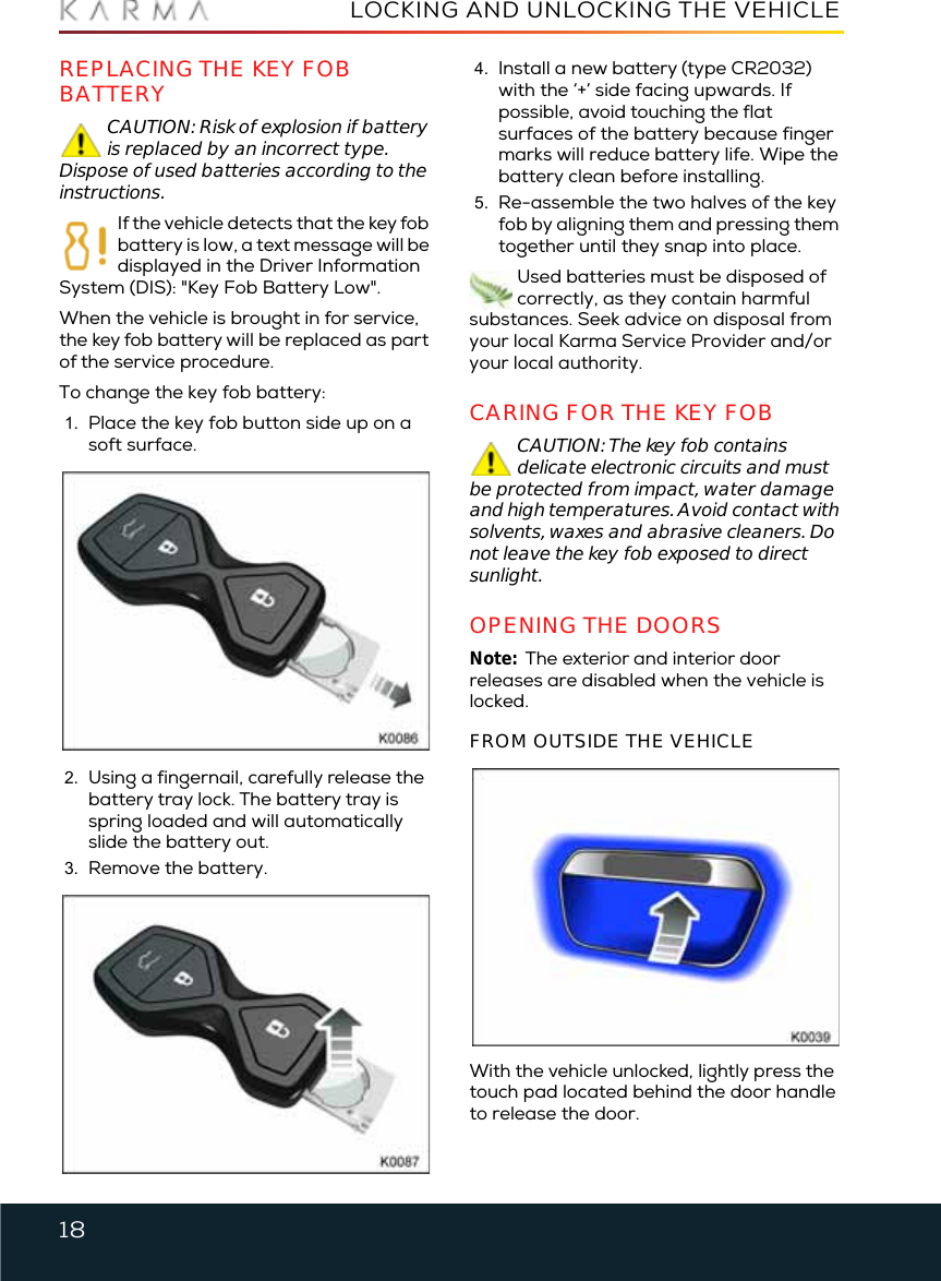
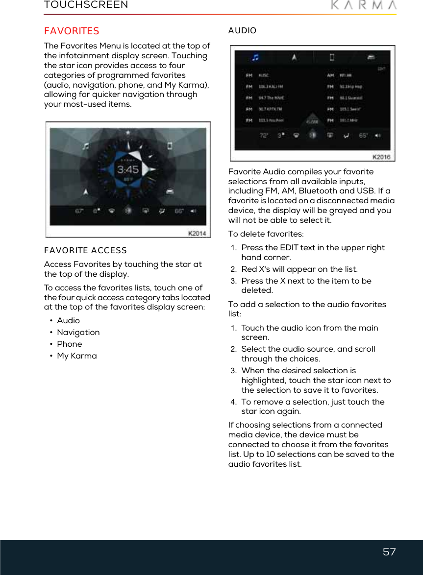
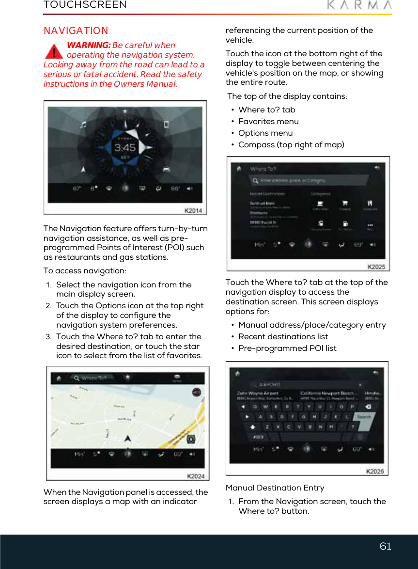
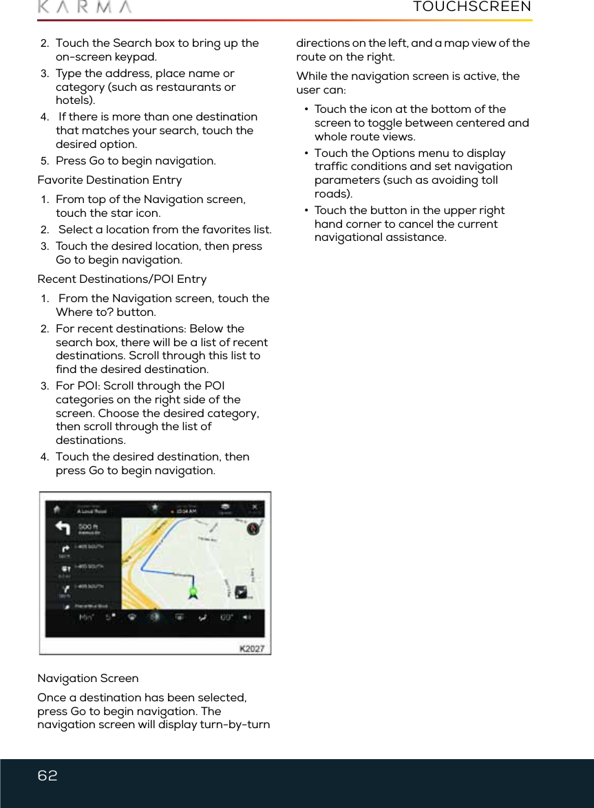
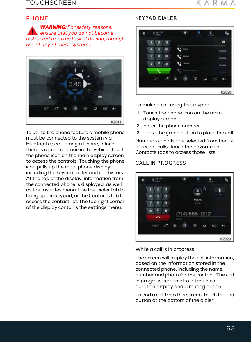
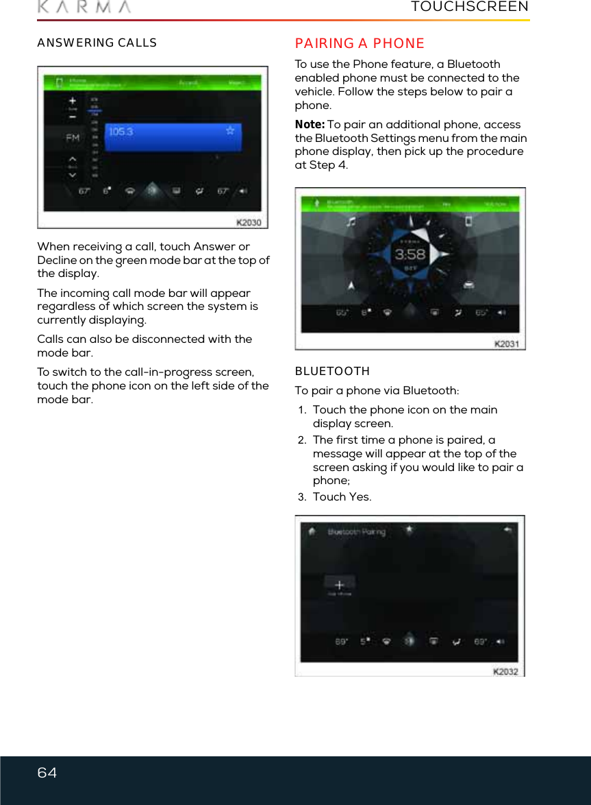
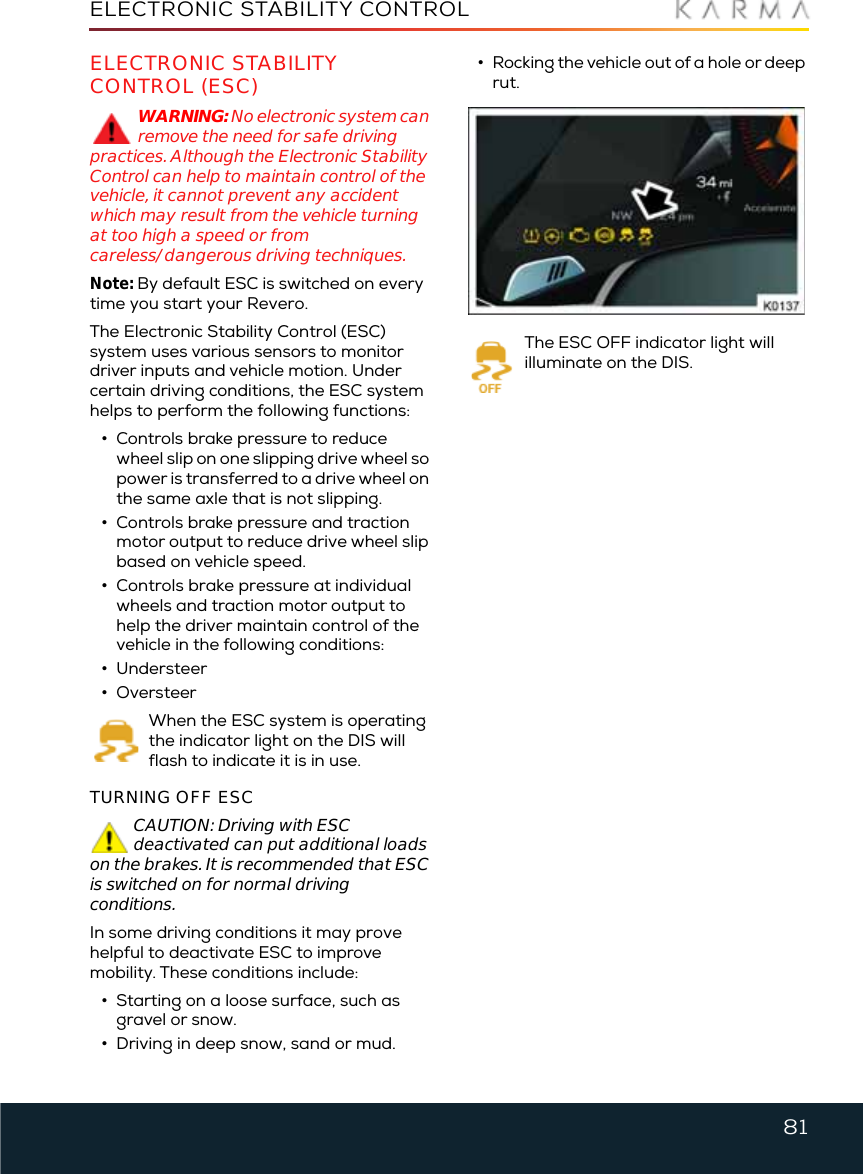
![16LOCKING AND UNLOCKING THE VEHICLELocking and Unlocking the VehicleABOUT THE KEY FOBThe vehicle security system, door locks, and ignition are controlled by the key fob. The doors and trunk can be either locked or unlocked using the key fob. The key fob is part of the immobilizer system. It operates in the manner described below.Passive entry to the vehicle is allowed when you activate the exterior door handle switch and you have a registered key on your person (in your pocket or in your purse). You can configure the setting to unlock the driver's door or all doors through the Central Infotainment Unit (CIU).The doors can be programmed to use the Passive Lock feature. When the vehicle is in Park [P], press the exterior door handle switch before closing the door. After the door closes, the doors will lock automatically and the park lights will flash, indicating successful activation of the security system.The key fob can also be used to activate the remote pre-conditioning feature.You have been supplied with two key fobs which also have an emergency key blade. OBTAINING REPLACEMENT KEYS AND KEY FOBSIf you lose a key fob or an emergency key blade, contact your local Karma Service Provider to obtain a replacement.When ordering a new key fob, bring all available key fobs for the vehicle to your Karma Service Provider to allow the system to be reprogrammed. If a key fob or the key number is not available, your Karma Service Provider can obtain the key code from a restricted access database.USING THE KEY FOBWARNING: Always remove the key fob from the vehicle any time you exit and walk away from the vehicle.CAUTION: Remove all key fobs from the vehicle when it is left unattended. This will ensure the vehicle is left in a secure condition.The buttons on the key fob operate as follows:1. Key Fob Lock: •Press once to lock the vehicle and activate the vehicle's security system. The vehicle's lights will briefly flash to confirm the security system is active.Passive Lock:•When exiting the vehicle, press the switch on the exterior door handle, close the door. All doors should lock and the parking lights should flash once, indicating the security system is active.•Press once, then press and hold the lock button for two seconds to activate the remote pre-conditioning feature. The lights will flash twice; one short and one long, to signal successful activation.](https://usermanual.wiki/Pektron-Group/005/User-Guide-3305050-Page-17.png)

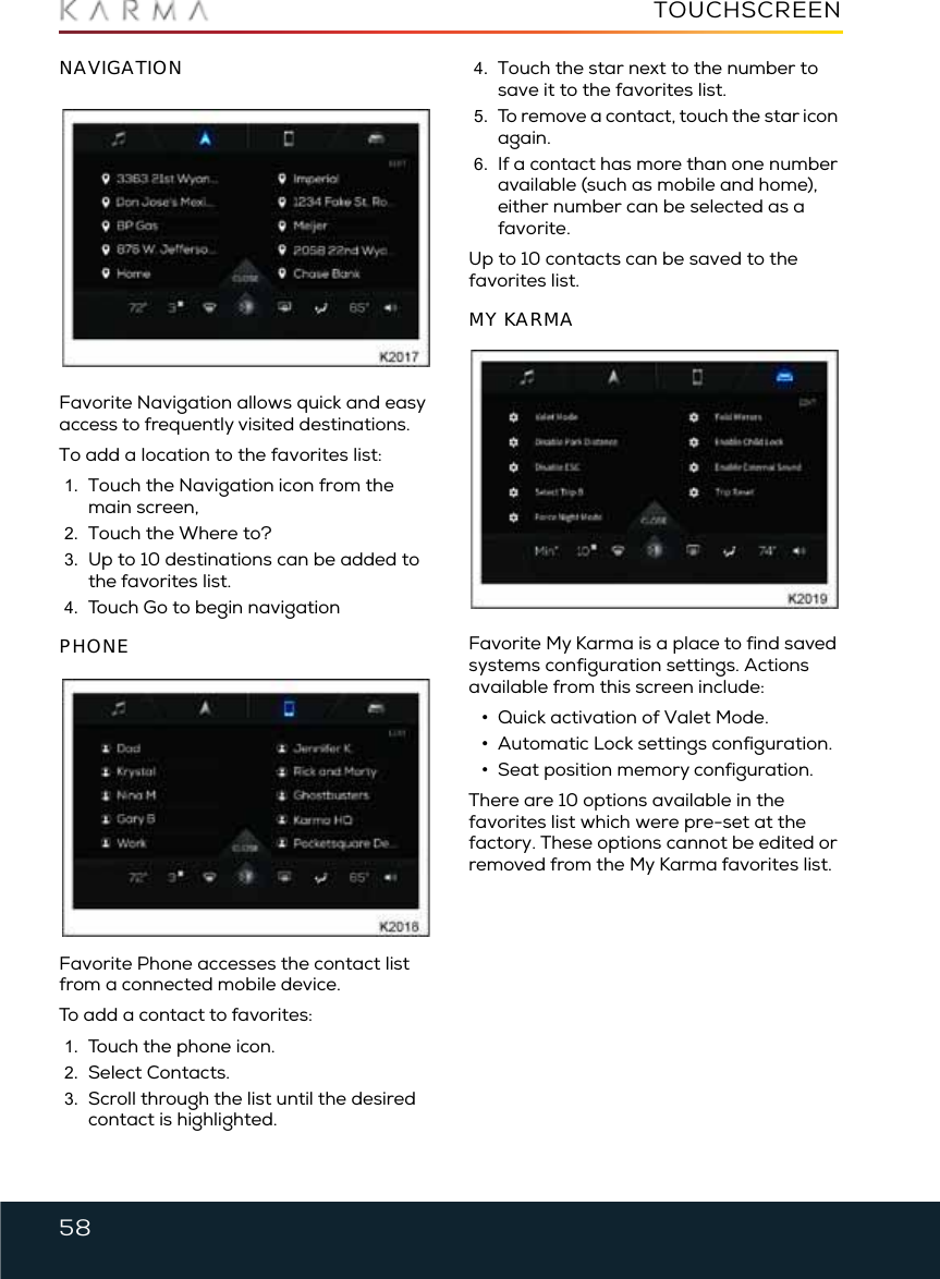
![29SEATS AND STEERING COLUMNThe Driver’s last used saved seat position will be automatically recalled if the following occurs:•The car is in Park [P].•A programmed key fob is present.•The driver’s door goes from “open” to “closed” (or the door is “open” and the driver places vehicle in vehicle in System Ready mode as if going to drive the car).•The Driver seat is not in the last saved seat position location.MEMORY SETTING PROCEDURE1. Select [SETTINGS].2. Select [INTERIOR].3. Select the Memory/Seat Position selection.4. Adjust the driver seat and steering wheel for Driver #1.5. Touch the “Set” selection (under the Primary Seat Memory selection).Repeat the above steps for the Secondary Seat Memory.EASY ENTRY AND EXITEntry and exit mode provides automatic movement of the steering column and driver’s seat making it easier to enter or exit the vehicle. Easy entry/exit is enabled and settings can be programmed in the CIU under the interior section located under vehicle settings.Note: This feature can be enabled or disabled via the vehicle’s touchscreen.ENTRYWhen a programmed key fob is detected outside the vehicle and the driver door goes from “closed” to “open.” The steering column and driver’s seat will return to the previous position.EXITWhen the vehicle is powered-down, the steering column will move to the uppermost tilt position and the driver’s seat will move to the exit position.Note: If the steering column or driver’s seat is adjusted during entry or exit operation, automatic movement will stop.](https://usermanual.wiki/Pektron-Group/005/User-Guide-3305050-Page-30.png)

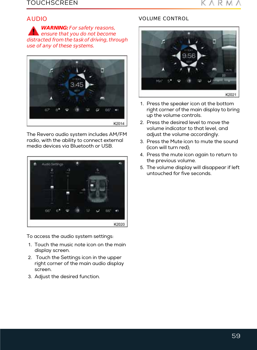
![83EXTERIOR SOUNDExterior SoundEXTERIOR SOUNDUnlike a traditional vehicle powered by an internal combustion engine, electric vehicles are inherently quiet at low speeds.Although this potentially provides a large benefit by reducing the levels of traffic noise from passing vehicles, sound also acts as a warning to other road users. It signifies the presence of a vehicle, its speed, direction and acceleration. To help reduce this safety risk, your Revero has been equipped with an exterior sound system to alert pedestrians and other road users to your presence.Two speakers are located on the exterior of your Revero, one under the front of the vehicle and another under the rear.USING THE SYSTEMNote: The exterior sound system is controlled automatically by the vehicle. There is no need for driver intervention.When the vehicle is put into Drive mode, the exterior sound system is switched on. A pulsing sound will be heard from the exterior speakers.As the vehicle’s speed increases, the pitch of the sound increases until the vehicle’s speed reaches approximately 30 mph (50 km/h). At this speed the volume of the sound will fade out and the exterior sound is turned off.The exterior sound will remain off until the vehicle’s speed is reduced to approximately 28 mph (45 km/h). At this speed, the exterior sound is switched on and the sound will fade in. As the vehicle slows, the pitch of the sound will decrease.Note: The exterior sound system remains active even when the vehicle is in [P] Park.](https://usermanual.wiki/Pektron-Group/005/User-Guide-3305050-Page-84.png)
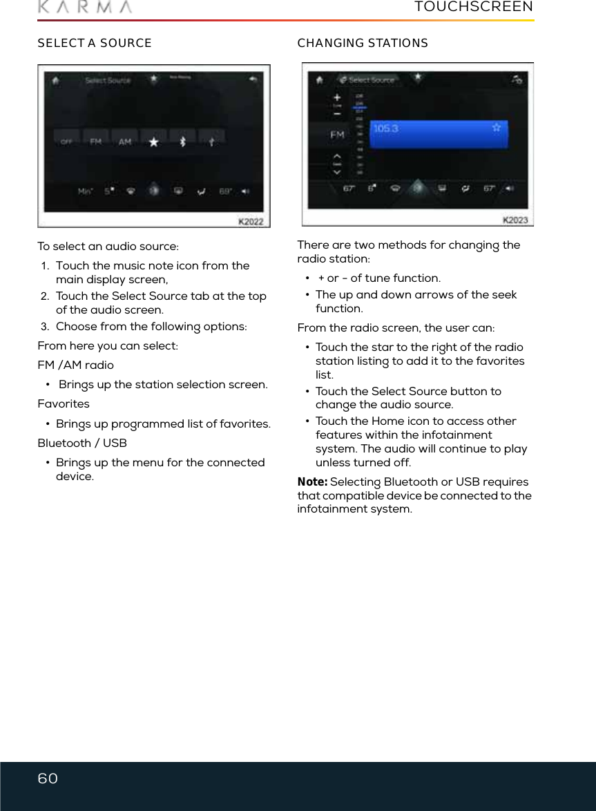
![95CHARGING THE VEHICLE2. Select Park [P] from the drive selection button, then press the Start/Stop button to take the vehicle out of Drive mode.The READY indicator on the DIS will turn off and the doors will unlock to indicate the vehicle is ready for charging.Note: If the cord is connected, the vehicle will automatically switch to Park [P].3. Open the charging port cover.4. Locate a wall outlet (Standard US 120V, 16A).5. Insert charger plug into wall outlet.6. Insert charge coupler into the charge port.7.While the vehicle is charging, the charging indicator light on the DIS will illuminate and the battery charge level indicator will begin to rise. Note: During charging or in high ambient temperatures, the cooling fans and coolant pumps may automatically switch on for a period of time to cool the cells in the battery. The fans and pumps may be audible when in operation. This is normal and not a cause for concern.Accessory modeDrive mode8. When the vehicle is fully charged, the DIS will be solid green with a percent of charge displayed. 9. Press the button on the charging connector to release the locking clip, then remove the connector from the charging port.](https://usermanual.wiki/Pektron-Group/005/User-Guide-3305050-Page-96.png)
![118CLEANING AND VEHICLE CARENote: If the 12 volt battery becomes discharged, the only way to open the doors will be to use the mechanical lock cylinder on the passenger side front door.1. Place the vehicle in Park [P] and DO NOT apply the parking brake.2. Turn the HVAC system ON for five minutes and set the vent setting to Recirculation mode. This will fully lubricate the seals and internal components and prevent dust from being able to enter the passenger compartment.3. Make sure the windows are closed and turn Off the HVAC system.4. Verify the key FOBs are not in the vehicle.5. Press the Start/Stop button to take the vehicle out of system Ready mode and power down the high voltage system. 6. Wait for car to go to sleep, approximately 1 minute.7. Connect an approved Absorbed Glass Mat (AGM) compatible battery maintainer to prevent it from discharging.Note: Standard battery maintainers can overcharge and cause damage to the 12 volt AGM battery used in the Karma and shorten its lifespan.STORING A VEHICLE FOR LONGER THAN FOUR WEEKSIf storing for two weeks or less, disconnecting the 12 volt auxiliary battery is not necessary.Long-term storage over three weeks will require the 12 volt battery and solar panel fuse to be disconnected. A battery maintainer is required to maintain the 12 volt battery voltage. Standard battery maintainers can overcharge and cause damage to the 12 volt AGM battery used in the Karma and shorten its lifespan.In preparation for storage, it is recommended that the HVAC system is turned ON for five minutes and set the vent setting to Recirculation mode. This will fully lubricate the seals and internal components and prevent dust from being able to enter the passenger compartment.Note: If storing for two weeks or less, disconnecting the 12 volt auxiliary battery is not necessary.1. Inflate the tires to 45 psi for storage purposes only. This will help reduce flat spots form developing.2. Verify mechanical keys will unlock and open the passenger side door using the mechanical lock. Note: If the 12 volt battery becomes discharged, the only way to open the doors will be to use the mechanical lock cylinder on the passenger side front door.1. Place the vehicle in Park [P] and DO NOT apply the parking brake.2. Turn the HVAC system ON for five minutes and set the vent setting to Recirculation mode. 3. Make sure the windows are closed and turn Off the HVAC system.4. Verify the key FOBs are not in the vehicle.5. Press the Start/Stop button to take the vehicle out of system Ready mode and power down the high voltage system. 6. Wait for car to go to sleep, approximately 1 minute.7. Disconnect the 12 volt battery negative (-) cable connector under the hood to prevent the battery from becoming discharged. 8. Disconnect the Solar Roof fuse #10 from the engine compartment fuse panel.9. Disconnect the 12 volt main connector located under the hood, on right fender.10. Wait 30 seconds.11. Connect an approved AGM compatible battery maintainer to prevent it from discharging.](https://usermanual.wiki/Pektron-Group/005/User-Guide-3305050-Page-119.png)
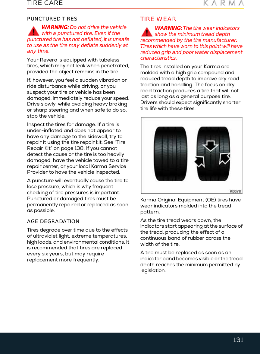
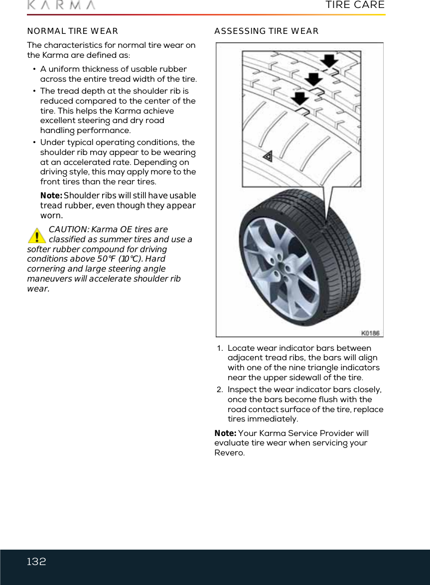
![130TIRE CARETire CareINSPECTION AND MAINTENANCEWARNING: The tires should be regularly checked for wear and to make sure that there are no cuts, bulges or exposure of the ply/cord structure. Do not drive with tires which are worn, damaged or inflated to the incorrect pressure. The safety of the vehicle and occupants will be adversely affected.WARNING: Poorly maintained and improperly used tires are dangerous.WARNING: Overloading the tires can cause overheating as a result of too much flexing. There could be a blowout and a serious crash. See Vehicle Load Limits.WARNING: Underinflated tires pose the same danger as overloaded tires. The resulting crash could cause serious injury.WARNING: Check all tires frequently to maintain the recommended pressure.WARNING: Tire pressure should be checked when the tires are cold.WARNING: Overinflated tires are more likely to be cut, punctured, or broken by a sudden impact — such as when hitting a pothole.WARNING: Keep tires at the recommended pressure.WARNING: Worn or old tires can cause a crash. If the tread is badly worn, replace them.WARNING: Replace any tires that have been damaged by impacts with potholes, curbs, etc.WARNING: Improperly repaired tires can cause a crash. Only the dealer or an authorized tire service center should repair, replace, dismount, and mount the tires.WARNING: Do not spin the tires excessively (greater than 35 mph [56 kmh]) on slippery surfaces such as snow, mud, ice, etc. Excessive spinning may cause the tires to explode.The Karma Revero does not use run-flat tires and does not have a spare tire. Always consider tire conditions when driving, and regularly inspect the tread and side walls for any sign of distortion (bulges), cuts or wear and adjust air pressures regularly.Good driving practice will improve the mileage you obtain from your tires, and avoid unnecessary damage.•Always ensure that the tire pressures are correctly adjusted.•Always observe the posted speed limits, and advisory speeds.•Avoid pulling away quickly, or hard acceleration.•Avoid making fast turns or braking sharply.•Avoid potholes and objects in the road.•Do not run over curbs or hit the tire against the curb when parking.CAUTION: Avoid contaminating tires with vehicle fluids that can cause damage.WHEEL ALIGNMENT AND TIRE BALANCEUnbalanced wheels (noticeable as vibration through the steering) may affect vehicle handling and tire life.Note: If tire wear is uneven (on one side of the tire only) or becomes abnormally excessive, the wheel alignment should be checked.TIRE ROTATIONBecause your Revero is equipped with different size tires on the front and rear wheels, the tires can only be moved from side to side on the same axle pair (front or rear).](https://usermanual.wiki/Pektron-Group/005/User-Guide-3305050-Page-131.png)
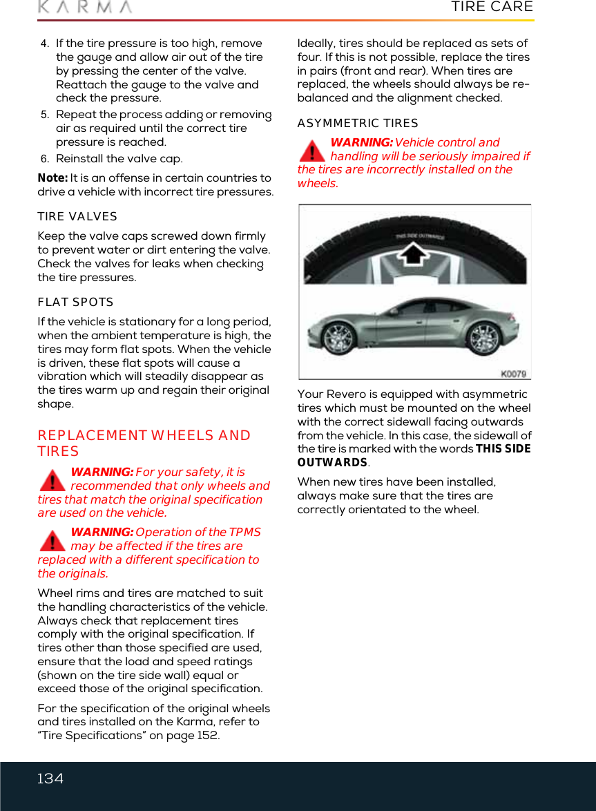
![136TIRE PRESSURE MONITORING SYSTEM (TPMS)Tire Pressure Monitoring Sys tem (TPMS)TIRE PRESSURE MONITORING SYSTEM (TPMS)Your vehicle will not have a spare tire and will not use run-flat tires. The driver is solely responsible to periodically check the tire pressures. In case the user installs run-flat tires on the vehicle, it falls under his/her responsibility to make sure that the tires are inflated to the correct pressure level to prevent a TPMS malfunction.Your vehicle has also been equipped with a TPMS malfunction indicator to indicate when the system is not operating properly. The TPMS malfunction indicator is provided by a separate telltale, which displays the symbol “TPMS” when illuminated.When the malfunction indicator is illuminated, the system may not be able to detect or signal low tire pressure as intended. TPMS malfunctions may occur for a variety of reasons, including the installation of replacement or alternate tires or wheels on the vehicle that prevent the TPMS from functioning properly. Always check the TPMS malfunction telltale after replacing one or more tires or wheels on your vehicle to ensure that the replacement or alternate tires and wheels allow the TPMS to continue to function properly.The TPMS is standard equipment in all Karma vehicles. The following conditions may trigger the warning light to turn on:•Low pressure soft (80% of recommended cold tire pressure)•Low pressure hard (23.2 PSI)•Fast pressure loss •Low battery chargeThe telltale icon will flash for 1 min if there is a system malfunction, then become stable until the malfunction is corrected.The CIU will display each sensor, showing its corresponding wheel temperature and pressure values. TIRE PRESSURE CORRECTIONThe tire pressure indicator light does not automatically turn off when the tire pressure is adjusted for all four tires. If the condition that is causing the TPMS icon to be illuminated is corrected, the vehicle must be powered-down normally, then re-energized and placed in System Ready mode. If the TPMS module registers all criteria as normal, the icon will go out. If a TPMS sensor detects a problem and the corrective action requires a repair or tire replacement, the tire position can be relearned manually.With the vehicle in Park [P] and in System Ready mode, you can enable the tire learning feature in the CIU by selecting:•Settings > Diagnostics> TPMS > Manual Re-learnOnce learning is enabled, change the pressure (either add air, or let some out) on the corresponding tire. The system will acknowledge the change in pressure with a single short chirp. You must follow this sequence:•Front Left (FL), Front Right (FR), Rear Right (RR), and Rear Left (RL)Before moving to the next wheel, wait for the system to issue a double chirp, signaling each wheel has been identified and the pressure value has been updated. The corresponding turn indicator will flash also. If for some reason the TPMS sensor could not be communicated, or it times out, a longer chime will sound, which means the](https://usermanual.wiki/Pektron-Group/005/User-Guide-3305050-Page-137.png)