Pektron Group 005 Karma Automotive Key Fob User Manual Karma User Handbook
Pektron Group Ltd Karma Automotive Key Fob Karma User Handbook
User Manual

KARMA REVERO
OWNER’S MANUAL

Karma Automotive, LLC
3080 Airway Avenue, Costa Mesa, California 92626
www.karmaautomotive.com
www.karmaautomotive.com/Manuals/My18Revero
Document Number: C1810ASD5082 (February 27, 2017 Edition)
© 2017 Karma Automotive, Inc. All rights reserved.
OWNER'S MANUAL
© 2017 Karma Automotive, LLC.
All rights reserved. Information contained in this document is based on the latest information available
at the time of printing. Reprinting, translation and copying are not permitted without prior authorization.
KARMA, REVERO and the Karma Logo are registered trademarks of Kara Automotive, LLC.
This Owner's Manual is to familiarize the owner of the vehicle of all normal operations and functions of
the vehicle. The content of this manual is correct for this vehicle at the time of publishing. The content of
the vehicle is subject to change.
This Page Intentionally Left Blank

3
INTRODUCTION .........................................................................................5
OVERVIEW................................................................................................. 11
VEHICLE SECURITY ................................................................................ 15
OCCUPANT SAFETY............................................................................... 25
CONTROLS AND OPERATION ............................................................. 43
POWER ...................................................................................................... 91
MAINTENANCE........................................................................................101
WHEELS AND TIRES .............................................................................129
TECHNICAL SPECIFICATIONS............................................................149
INDEX.......................................................................................................................INDEX-1
This Page Intentionally Left Blank

5
INTRODUCTION
Introduction
INTRODUCTION
Welcome to the Karma Family............................................................................................................6
Using This Manual....................................................................................................................................6
Symbols Glossary....................................................................................................................................6
Notes About This Manual......................................................................................................................6
INFORMATION ABOUT YOUR VEHICLE
Electric Vehicle Precautions.................................................................................................................7
Maintenance and Repairs to Your Vehicle......................................................................................7
Body Repairs.............................................................................................................................................7
Vehicle Modifications..............................................................................................................................8
Quality Control..........................................................................................................................................8
California Proposition 65......................................................................................................................8
California Perchlorate Advisory.........................................................................................................8
Data Recording........................................................................................................................................8
CONSUMER INFORMATION
If You Need Assistance.........................................................................................................................10
Reporting Safety Defects...................................................................................................................10

6
INTRODUCTION
Introduction
WELCOME TO THE KARMA
FAMILY
On behalf of Karma Automotive, thank you
for purchasing one of our vehicles.
Your Karma is designed to deliver a unique
combination of advanced technology with
timeless design.
We are committed to providing you with an
ownership experience that is second to
none, and we look forward to serving you in
the years ahead.
USING THIS MANUAL
For your own safety, follow the instructions
and warnings contained in this manual.
Ignoring them could result in damage to the
vehicle or personal injury to you or others.
Vehicle damage caused by failing to follow
instructions is not covered by the New
Vehicle Limited Warranty.
Keep this manual in your vehicle as a
reference for the safe and enjoyable use of
your vehicle. Should you sell your car, leave
this manual with it for the next owner.
If you are unable to find the information
you need, it may be contained within one of
the additional documents included in your
Owner’s literature pack:
•Quick Reference Guide - a summarized
version of this document allowing you to
quickly familiarize yourself with the
vehicle.
•Infotainment Online Emulator -
describes how to use the features of the
touch-screen.
•Warranty and Service - details of the
vehicle warranty and servicing
requirements for your vehicle.
•Roadside Assistance - details the
complimentary benefits and services
provided to Karma vehicle owner.
SYMBOLS GLOSSARY
The following symbols used within this
manual call your attention to specific types
of information.
WARNING: Indicates either an
instruction which must be followed
precisely, or information that should be
considered with great care in order to
avoid the possibility of personal injury or
injury to others.
CAUTION: Indicates either an
instruction which must be followed
precisely, or information that should be
considered with great care in order to
avoid the possibility of damage to your
vehicle.
This symbol identifies instructions
that should be observed in order to
prevent unnecessary damage to the
environment.
NOTES ABOUT THIS MANUAL
All specifications and descriptions are
accurate at the time of printing.
Continuous improvement is a constant
goal at Karma Automotive, therefore we
reserve the right to make changes to this
manual at any time, without notice and
without obligation.
Note: This manual applies to all Karma
models. As a result, you may find some
explanations for equipment or options not
installed on your vehicle.
Note: This manual describes product
features and options that may not be
available at the time of publication. It may
also describe options not equipped to your
vehicle.
Note: Some of the illustrations in this
manual may differ slightly from your
vehicle.
Copyright © 2017 Karma Automotive, LLC.
All rights reserved.

7
INFORMATION ABOUT YOUR VEHICLE
Information About Your Vehicle
ELECTRIC VEHICLE
PRECAUTIONS MAINTENANCE AND REPAIRS TO
YOUR VEHICLE
Karma Automotive recommends having
maintenance and repairs for your Karma
performed by an authorized Karma Service
Provider.
To locate your nearest authorized Karma
Service Provider, go to
www.karmaautomotive.com or contact
Karma Consumer Affairs.
BODY REPAIRS
If you're involved in a collision, you want
your vehicle to be returned to its
pre-accident condition when repaired.
That's why it is important to make sure your
vehicle is repaired with only genuine Karma
Automotive parts.
Some repair shops and insurance
companies may suggest using non-original
equipment or salvaged parts to save
money. However, these parts may not
meet Karma's high standards for quality, fit
and corrosion resistance. In addition, non-
original equipment and salvaged parts
(and any damage or failures they may
cause) are not covered by any Karma
warranty.
The best way to ensure that your vehicle is
repaired with genuine Karma Automotive
parts is to take it to a Karma Service
Provider. Each Service Provider works with
selected collision repair centers that meet
Karma's strict requirements for training,
equipment, quality, and customer
satisfaction. These repair centers use
genuine Karma Automotive parts
exclusively in the repair of Karma vehicles.
IMPORTANT
Your Karma is an electric vehicle with a
range-extending gasoline engine.
WARNING: The Karma has both
high-voltage Direct Current (DC)
and Alternating Current (AC) systems as
well as a 12-volt system. Both the DC and
AC high voltage systems are very
dangerous and can cause personal
injury, severe burns, electric shock and
even fatal injury unless appropriate
precautions are taken.
WARNING: Always observe and
obey the instructions on labels
attached to components on the vehicle,
they are for your safety.
WARNING: Do not touch, attempt
to remove or replace any high
voltage parts, wiring (identified by the
orange outer sleeving) or connectors.
WARNING: If the vehicle is involved
in an accident, do not touch any
high voltage wiring, connectors or the
components connected to the wiring.
WARNING: If a vehicle fire occurs,
extinguish it with a Class D
powder-type fire extinguisher.

8
INFORMATION ABOUT YOUR VEHICLE
VEHICLE MODIFICATIONS
WARNING: The installation of non-
approved parts and accessories, or
the carrying out of non-approved
modifications, may be dangerous and
could affect the safety of the vehicle and
occupants, and also invalidate the terms
and conditions of the vehicle warranty.
WARNING: Karma Automotive will
not accept any liability for death,
personal injury or damage to property
which may occur as a direct result of non-
approved modifications or the installation
of non-approved accessories.
If you have a disability which may require
modification to the vehicle, please contact
Karma Automotive before any
modifications are made.
QUALITY CONTROL
You may have noticed a few miles/kms on
the odometer when you took delivery of
your Revero. Some of these miles were a
result of the comprehensive process used
to ensure the quality of your Revero.
This process includes extensive inspections
during and after production. The final
inspection takes place at the selling
Retailer and includes a road test
conducted by a trained Karma Automotive
Technician.
CALIFORNIA PROPOSITION 65
WARNING: Certain vehicle
components contain or emit
chemicals known to the State of California
to cause cancer and birth defects or other
reproductive harm. In addition, certain
fluids contained in vehicles and certain by-
products of component wear contain or
emit chemicals known to the State of
California to cause cancer and birth
defects or other reproductive harm.
CALIFORNIA PERCHLORATE
ADVISORY
WARNING: Certain components of
this vehicle such as air bag modules,
seat belt pre-tensioners and Lithium
batteries may contain Perchlorate
Material. Special handling may apply for
service or vehicle end of life disposal. See
http://www.dtsc.ca.gov/hazardouswaste/
perchlorate.
DATA RECORDING
SERVICE DATA RECORDING
Service data recorders in your vehicle are
capable of collecting and storing diagnostic
information about your vehicle. This
potentially includes information about the
performance or status of various systems
and modules in the vehicle such as engine,
throttle, steering or brakes. In order to
properly diagnose and service your vehicle,
Karma Automotive and its authorized
service facilities may access vehicle
diagnostic information through a direct
connection to your vehicle.
EVENT DATA RECORDING
This vehicle is equipped with an Event Data
Recorder (EDR). The main purpose of an
EDR is to record, in certain crash or near
crash-like situations, such data (as an air
bag deployment or hitting a road obstacle),
will assist in understanding how a vehicle's
systems performed. The EDR is designed to
record data related to vehicle dynamics
and safety systems for a short period of
time, typically 30 seconds or less.
The EDR in this vehicle is designed to record
such data as:
•How various systems in your vehicle
were operating.
•Whether or not the driver and
passenger safety belts were
buckled/fastened.
•How far (if at all) the driver was
depressing the accelerator and/or
brake pedal.
•How fast the vehicle was traveling.

9
INFORMATION ABOUT YOUR VEHICLE
•Where the driver was positioning the
steering wheel.
This data can help provide a better
understanding of the circumstances in
which crashes and injuries occur.
Note: EDR data is recorded by your vehicle
only if a non-trivial crash situation occurs;
no data is recorded by the EDR under
normal driving conditions and no personal
data (e.g., name, gender, age, and crash
location) is recorded. However, other
parties, such as law enforcement, could
combine the EDR data with the type of
personally identifying data routinely
acquired during a crash investigation.
To read data recorded by an EDR, special
equipment is required, and access to the
vehicle or the EDR is needed. In addition to
the vehicle manufacturer, other parties,
such as law enforcement, that have the
special equipment, can read the
information if they have access to the
vehicle or the EDR.

10
CONSUMER INFORMATION
Consumer Information
IF YOU NEED ASSISTANCE
Both Karma Automotive and your Karma
Retailer are dedicated to serving your
automotive needs. Your complete
satisfaction is our first priority. Should you
have a problem or concern, please take the
following steps to ensure the quickest
possible response:
Step 1 - Discuss the situation with an
appropriate member of your Retailer team
such as the Service Manager or Customer
Satisfaction Manager.
If necessary, escalate to the Retailer owner
or General Manager for assistance. In most
cases, a satisfactory solution can be
reached at this step.
Step 2 - If your Retailer does not address
your concern to your satisfaction, please
contact the Karma Client Services Team:
clientservices@karmaautomotive.com
(855) 56-KARMA (52762)
You may also contact us by mail at:
Karma Client Services
2975 Red Hill Ave.
Suite 200
Costa Mesa, CA 92626
Whether calling or writing, please provide
the following information:
•17-digit Vehicle Identification Number
(VIN) found on the vehicle registration
paperwork and on the certification label
located on the driver's door pillar.
•Current vehicle odometer reading.
•Name of your selling and servicing
Karma Retailers.
•Your day and evening contact
telephone numbers.
•Your email address.
REPORTING SAFETY DEFECTS
UNITED STATES
If you believe that your vehicle has a defect
which could cause a crash or could cause
injury or death, you should immediately
inform the National Highway Traffic Safety
Administration (NHTSA) in addition to
notifying Karma Automotive.
If NHTSA receives similar complaints, it
may open an investigation, and if it finds
that a safety defect exists in a group of
vehicles, it may order a recall and remedy
campaign. However, NHTSA cannot
become involved in individual problems
between you, your Retailer, or Karma
Automotive.
To contact NHTSA, you may call the Vehicle
Safety Hotline toll-free at 1-888-327-
4236 (TTY: 1-800-424-9153); go to
http://www.safercar.gov; or write to:
National Highway Traffic Safety
Administration
1200 New Jersey Avenue SE.
Washington, DC 20590.
You can also obtain other information
about motor vehicle safety from
http://www.safercar.gov.
CANADA
If you believe that your vehicle has a defect
which could cause a crash or could cause
injury or death, you should immediately
inform Transport Canada, in addition to
notifying Karma Automotive.
To contact Transport Canada, call their
toll-free number: 1-800-333-0510.

11
OVERVIEW
Overview
EXTERIOR
Exterior Overview..................................................................................................................................12
INTERIOR
Interior Overview...................................................................................................................................13
12
EXTERIOR
Exterior
EXTERIOR OVERVIEW
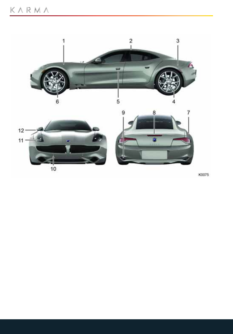
1. Hood. See “Hood” on page 105.
2. Solar roof. See “Cleaning and Vehicle
Care” on page 114.
3. Charging port cover. See “Charging the
Vehicle” on page 92.
4. Tire Pressure Monitoring System
(TPMS). See “Tire Pressure Monitoring
System (TPMS)” on page 136.
5. Exterior door release. See “Locking and
Unlocking the Vehicle” on page 16.
6. Wheels and tires. See “Tire Care” on
page 130.
7. Fuel filler cover. See “Fuel Filling” on
page 98.
8. Trunk. See “Trunk” on page 21.
9. Exterior sound. See “Exterior Sound” on
page 83.
10. Vehicle recovery eye. See “Vehicle
Recovery” on page 124.
13
INTERIOR
Interior
INTERIOR OVERVIEW
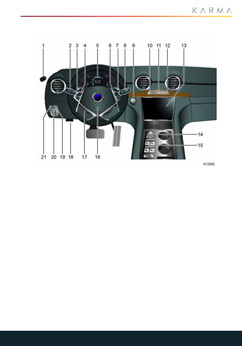
1. Exterior mirror control. See “Exterior
Mirrors” on page 54.
2. Exterior lights and turn signal. See
“Exterior Lighting” on page 51.
3. STEALTH, SPORT, SUSTAIN mode
selection. See “Driving Modes” on
page 76.
4. Audio and phone controls. See “Using
the Touchscreen” on page 55.
5. Driver Information System (DIS). See
“Driver Information System (DIS) USA
Specification” on page 45.
6. Cruise control. See “Cruise Control” on
page 82.
7. REGEN mode selection. See “REGEN
mode” on page 77.
8. Wipers and washers. See “Wipers and
Washers” on page 50.
9. Start/Stop button. See “Starting the
Vehicle” on page 73.
10. Master door locking. See “Master Lock
and Unlock Switch” on page 19.
11. Hazard warning flashers. See “Hazard
Warning Flashers” on page 52.
12. Glove compartment open. See “Glove
Compartment” on page 22.
13. Touchscreen. See “Using the
Touchscreen” on page 55.
14. Mode selector. See “Using the
Touchscreen” on page 55.
15. Power window controls. See “Power
Windows” on page 53.
16. Horn.
17. Steering column adjustment. See
“Steering Column Position” on page 26.
18. Hood release (recessed). See “Hood” on
page 105.
19. Fuel filler cover release. See “Fuel Filler”
on page 98.
20. Parking brake. See “Parking Brake” on
page 79.
21. Trunk release. See “Trunk Interior
Release Handle” on page 21.
This Page Intentionally Left Blank

15
VEHICLE SECURITY
Vehicle Sec urity
LOCKING AND UNLOCKING THE VEHICLE
About the Key FOB................................................................................................................................16
Using the Key FOB.................................................................................................................................16
Medical Safety.........................................................................................................................................17
Replacing the Key FOB Battery........................................................................................................18
Caring for the Key FOB........................................................................................................................18
Opening the Doors................................................................................................................................18
Master Lock and Unlock Switch........................................................................................................19
Automatic Locking.................................................................................................................................19
Child Safety Locks.................................................................................................................................19
Emergency Access ................................................................................................................................19
TRUNK
Opening the Trunk .................................................................................................................................21
Trunk Interior Release Handle...........................................................................................................21
GLOVE COMPARTMENT AND VALET MODE
Glove Compartment............................................................................................................................22
Valet Mode..............................................................................................................................................22
16
LOCKING AND UNLOCKING THE VEHICLE
Locking and Unlocking the Vehicle
ABOUT THE KEY FOB
The vehicle security system, door locks, and
ignition are controlled by the key fob. The
doors and trunk can be either locked or
unlocked using the key fob. The key fob is
part of the immobilizer system. It operates
in the manner described below.
Passive entry to the vehicle is allowed when
you activate the exterior door handle
switch and you have a registered key on
your person (in your pocket or in your
purse). You can configure the setting to
unlock the driver's door or all doors through
the Central Infotainment Unit (CIU).
The doors can be programmed to use the
Passive Lock feature. When the vehicle is in
Park [P], press the exterior door handle
switch before closing the door. After the
door closes, the doors will lock
automatically and the park lights will flash,
indicating successful activation of the
security system.
The key fob can also be used to activate the
remote pre-conditioning feature.
You have been supplied with two key fobs
which also have an emergency key blade.
OBTAINING REPLACEMENT KEYS AND
KEY FOBS
If you lose a key fob or an emergency key
blade, contact your local Karma Service
Provider to obtain a replacement.
When ordering a new key fob, bring all
available key fobs for the vehicle to your
Karma Service Provider to allow the
system to be reprogrammed. If a key fob or
the key number is not available, your
Karma Service Provider can obtain the key
code from a restricted access database.
USING THE KEY FOB
WARNING: Always remove the key
fob from the vehicle any time you exit
and walk away from the vehicle.
CAUTION: Remove all key fobs from
the vehicle when it is left unattended.
This will ensure the vehicle is left in a secure
condition.
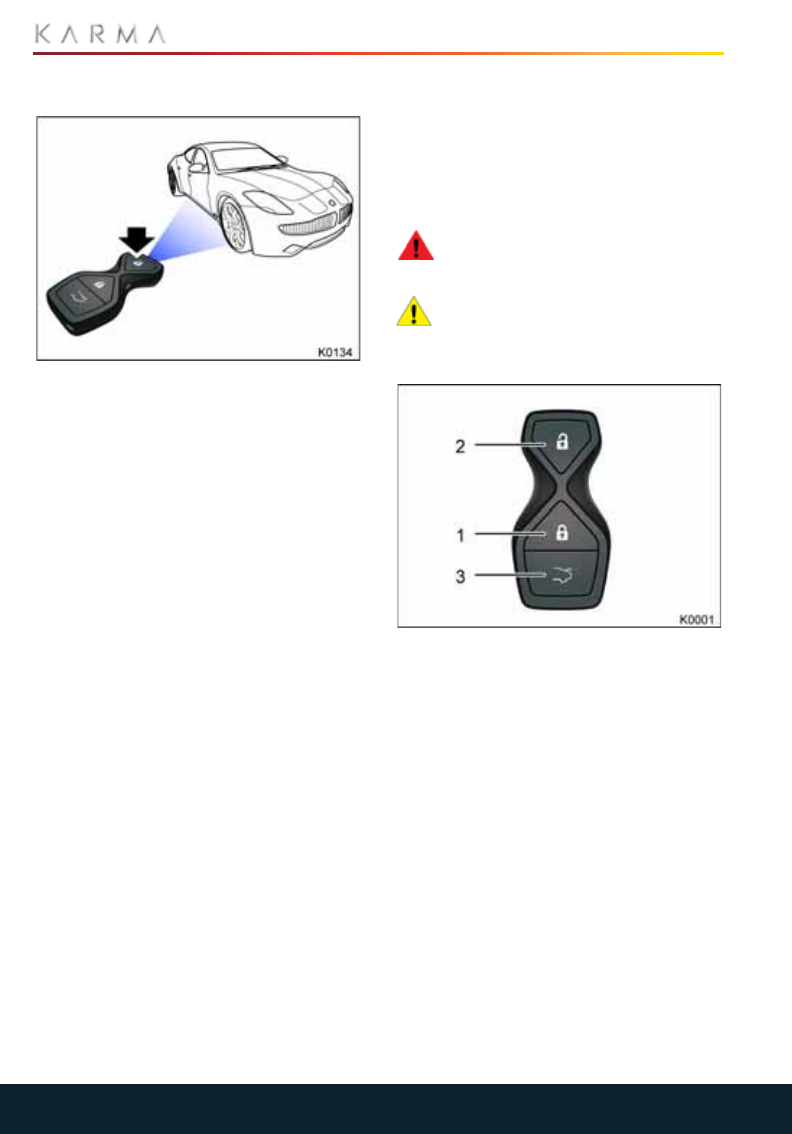
The buttons on the key fob operate as
follows:
1. Key Fob Lock:
•Press once to lock the vehicle and
activate the vehicle's security system.
The vehicle's lights will briefly flash to
confirm the security system is active.
Passive Lock:
•When exiting the vehicle, press the
switch on the exterior door handle,
close the door. All doors should lock
and the parking lights should flash
once, indicating the security system is
active.
•Press once, then press and hold the
lock button for two seconds to
activate the remote pre-conditioning
feature. The lights will flash twice; one
short and one long, to signal
successful activation.
17
LOCKING AND UNLOCKING THE VEHICLE
2. Key Fob Unlocking:
•Press unlock button once to unlock
the driver door. Press a second time
to unlock all doors.
•The horn should sound once and the
park lights should flash once.
Passive Unlock:
•When a programmed key fob is in
your possession, activate an exterior
door handle. The driver door should
unlock.
•The horn should sound once and the
park lights should flash once.
•This feature can be programmed to
unlock all doors through the CIU.
3. Trunk
•Press and hold the trunk release
button for 3 seconds to unlock the
trunk.
Note: The lock and unlock settings for your
Revero can be configured to your personal
preferences via the touchscreen.
The buttons on the key fob transmit a
coded radio signal to a receiver in your
Revero. It is not necessary to point the key
fob at your vehicle, but you must be within
operating range. The operating range will
vary according to the condition of the key
fob battery and other physical factors.
If the vehicle cannot be locked or unlocked
using the buttons on the key fob, you may
need to change the key fob battery.
Note: Interference from other radio
equipment operating on a similar
frequency may also affect the operation of
the key fob. If this happens, operate the key
fob as close to your vehicle as possible. If
you are still unable to unlock your vehicle
with the key fob, use the manual door lock.
MEDICAL SAFETY
WARNING: Any person with an
implanted medical device should
ensure that the device is kept at a distance
of at least 8.7 inches (22 cm) away from
any transmitter mounted in the vehicle.
This is to avoid any possibility of
interference between the system and the
device. Interference may cause the
implanted medical device to malfunction,
causing serious injury or death.
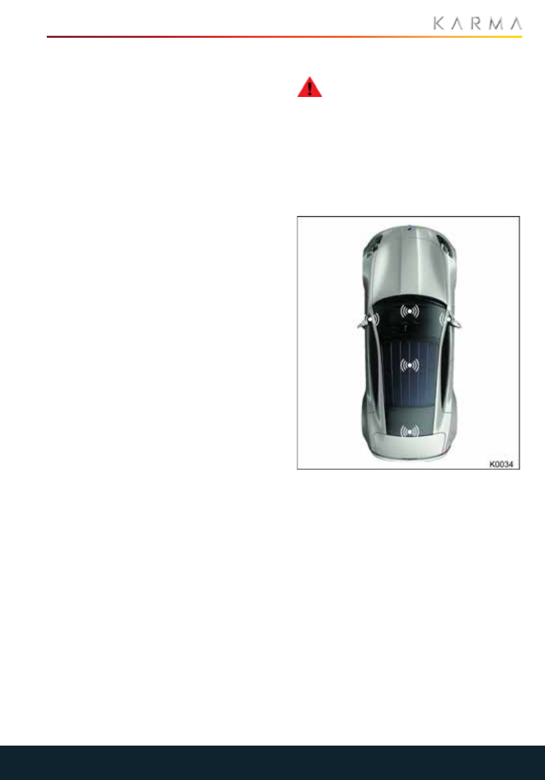
Transmitters which detect the presence of
the key fob are located in the following
locations on your Revero:
1. Behind the touchscreen.
2. Beneath the center console.
3. Trunk - underside of the rear parcel
shelf.
18
LOCKING AND UNLOCKING THE VEHICLE
REPLACING THE KEY FOB
BATTERY
CAUTION: Risk of explosion if battery
is replaced by an incorrect type.
Dispose of used batteries according to the
instructions.
If the vehicle detects that the key fob
battery is low, a text message will be
displayed in the Driver Information
System (DIS): "Key Fob Battery Low".
When the vehicle is brought in for service,
the key fob battery will be replaced as part
of the service procedure.
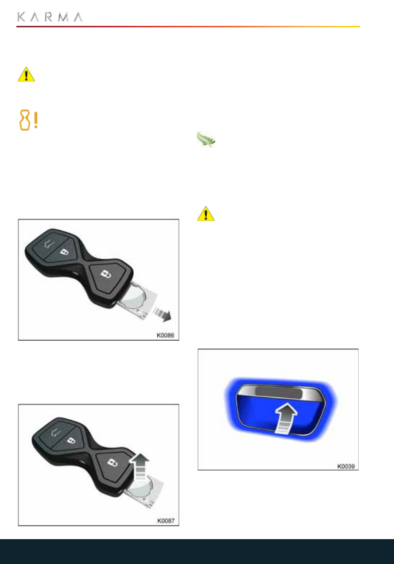
To change the key fob battery:
1. Place the key fob button side up on a
soft surface.
2. Using a fingernail, carefully release the
battery tray lock. The battery tray is
spring loaded and will automatically
slide the battery out.
3. Remove the battery.
4. Install a new battery (type CR2032)
with the ‘+’ side facing upwards. If
possible, avoid touching the flat
surfaces of the battery because finger
marks will reduce battery life. Wipe the
battery clean before installing.
5. Re-assemble the two halves of the key
fob by aligning them and pressing them
together until they snap into place.
Used batteries must be disposed of
correctly, as they contain harmful
substances. Seek advice on disposal from
your local Karma Service Provider and/or
your local authority.
CARING FOR THE KEY FOB
CAUTION: The key fob contains
delicate electronic circuits and must
be protected from impact, water damage
and high temperatures. Avoid contact with
solvents, waxes and abrasive cleaners. Do
not leave the key fob exposed to direct
sunlight.
OPENING THE DOORS
Note: The exterior and interior door
releases are disabled when the vehicle is
locked.
FROM OUTSIDE THE VEHICLE
With the vehicle unlocked, lightly press the
touch pad located behind the door handle
to release the door.
19
LOCKING AND UNLOCKING THE VEHICLE
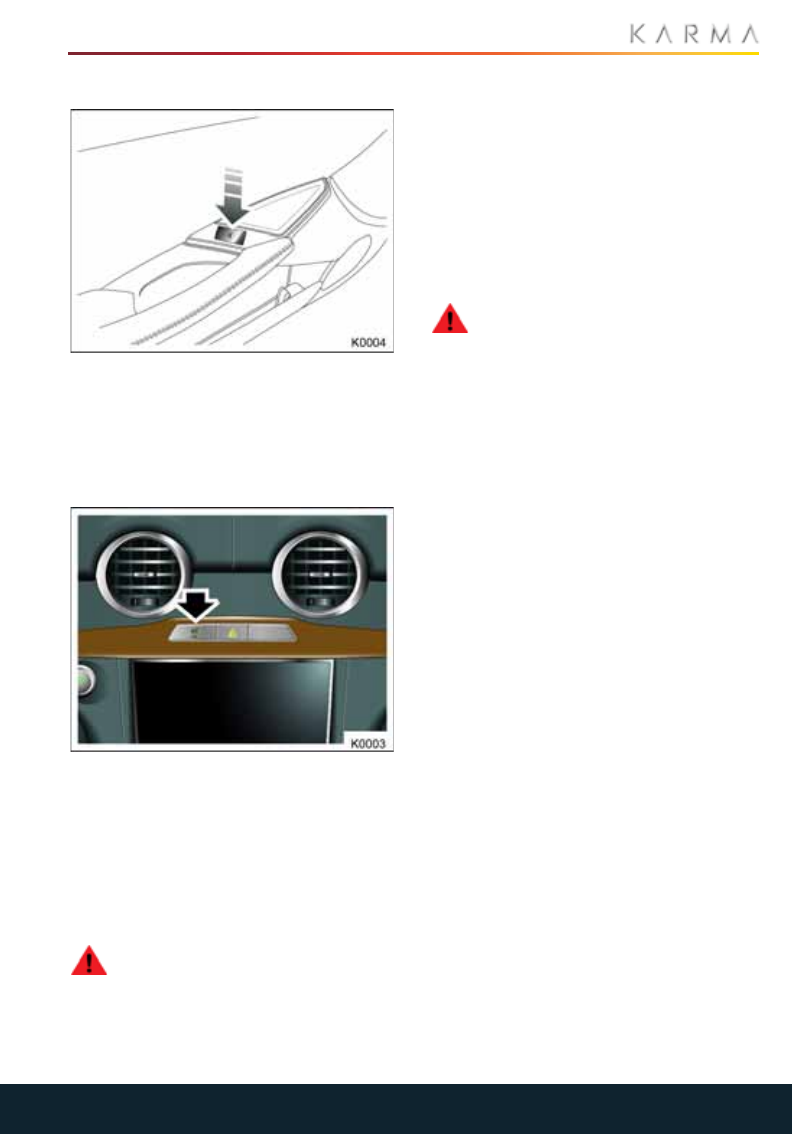
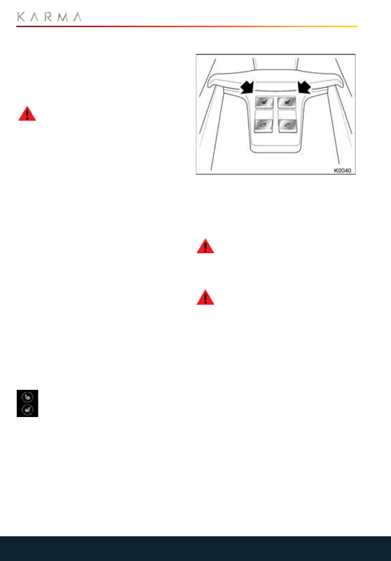
FROM INSIDE THE VEHICLE
To open the door from the interior of the
vehicle, press the arrowed switch on the
interior door panel.
MASTER LOCK AND UNLOCK
SWITCH
To lock or unlock all the doors while in the
vehicle, press the master locking switch
arrowed above.
When any door is unlocked or open, an
amber indicator on the switch will
illuminate.
AUTOMATIC LOCKING
WARNING: Never adjust the Settings
in the CIU while you are driving your
vehicle, even if you are temporarily
stopped. Wait until you are in a safe
location away from traffic, put the vehicle
in Park, and then access the Settings menu.
Dependent upon configuration, the
vehicle's doors will either lock automatically
when a speed of 5 mph (8 km/h) is reached
or when D (Drive) or R (Reverse) is selected.
The Automatic Locking configuration can
be programed from the home screen:
1. From MyKarma, select Settings.
2. Select Interior then Auto Door Lock.
3. Configure the auto door lock function to
the desired settings.
WARNING: Never adjust the Settings
in the CIU while you are driving your
vehicle, even if you are temporarily
stopped. Wait until you are in a safe
location away from traffic, put the vehicle
in Park, and then access the Settings menu.
CHILD SAFETY LOCKS
Child safety locks are installed on both of
the rear doors to prevent children from
using the rear door switches and
accidentally opening the doors when the
vehicle is in motion or parked.
The child safety locks are automatically
activated by inhibiting the operation of the
rear windows, see “Rear window inhibit” on
page 53.
It is recommended that the child safety
locks are activated whenever children are
being carried in the rear seats.
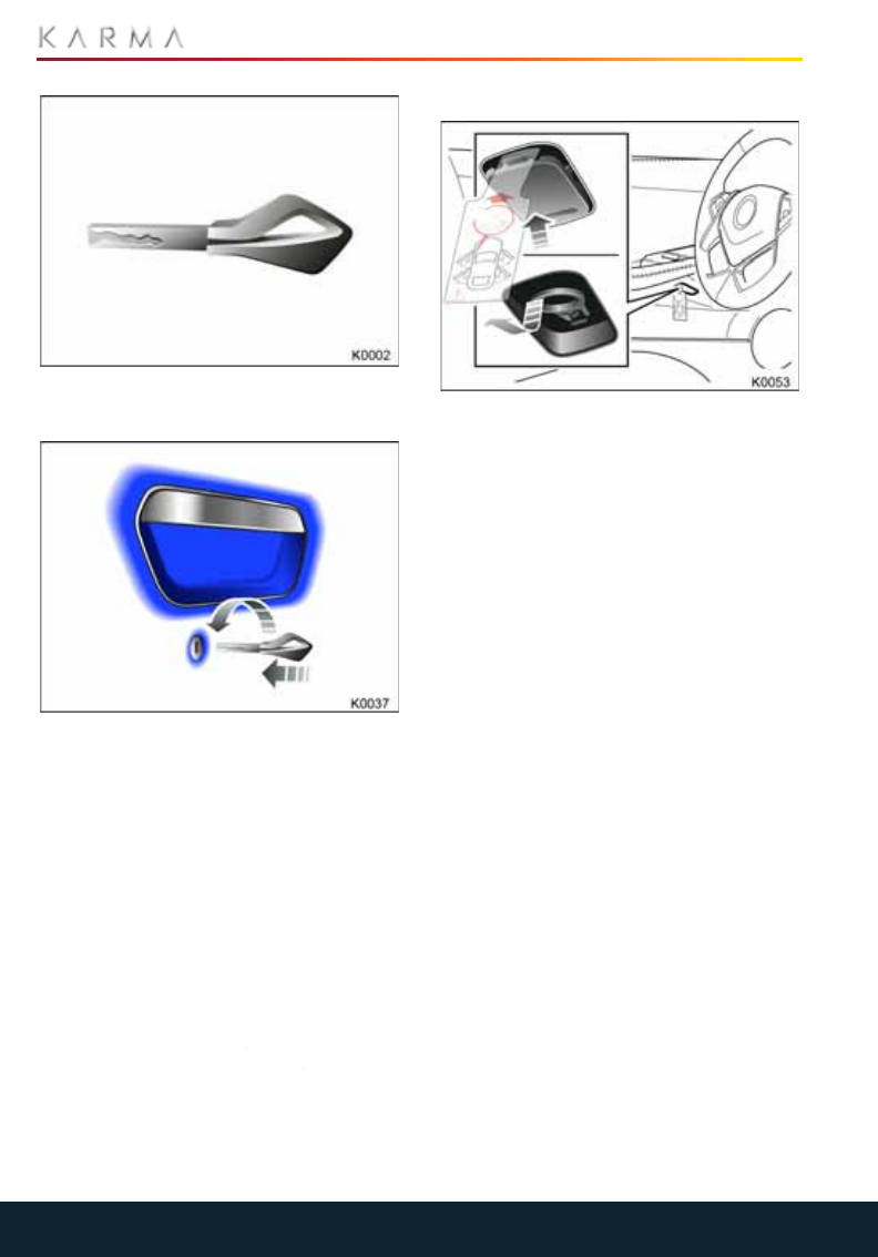
EMERGENCY ACCESS
EMERGENCY UNLOCKING
If the key fob buttons fail to unlock, lock or
open the trunk, replace the key fob battery.
If the key fob still fails to unlock the vehicle,
you can unlock the passenger's door using
the key blade.
Note: It is recommended that you keep the
mechanical key in the carrying case
provided or in a secure location easily
accessible.
20
LOCKING AND UNLOCKING THE VEHICLE
Press the button on the reverse of the key
fob and slide the key blade free.
Insert the blade into the lock located below
the passenger door handle. Turn the key
counter clockwise to open the door.
The vehicle's alarm will sound when the
door is opened. To switch off the alarm,
press the brake pedal and press the
Start/Stop button. If a recognized key fob is
detected, the alarm will be deactivated
and the vehicle will enter Drive mode.
Note: The alarm is also deactivated when
the vehicle enters Accessory mode (as long
as a valid key fob is recognized).
Note: If this fails to work, use the keyless
start backup procedure. See “Keyless start
backup procedure” on page 74.
MANUAL DOOR OPENING
In the event of a power failure, each of the
doors can be manually opened from inside
the vehicle by pulling the release cable
located below the door handle.
To access the release cable, press the
lower edge of the cover below the door
handle and remove the cover.
21
TRUNK
Trunk
OPENING THE TRUNK
To open the trunk, either press the trunk
release button on the key fob twice in quick
succession or press the trunk release
button on the left-hand dashboard closing
panel.
To close, firmly apply downward pressure
to the center of the trunk lid.
Note: The trunk release button is disabled if
the vehicle is locked, Valet mode is enabled
when the vehicle’s speed exceeds 5 mph (8
km/h).
Note: The trunk will automatically reopen if
the key fob is detected inside the trunk
compartment.
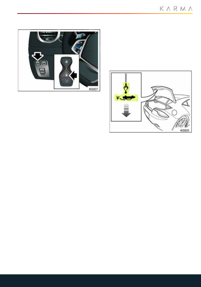
TRUNK INTERIOR RELEASE
HANDLE
Your Revero is equipped with a mechanical
trunk release handle that provides a means
of escape in the event that a person
becomes locked inside the trunk. Adults are
advised to familiarize themselves with the
operation and location of the release
handle.
A T-shaped handle is located inside the
trunk above the latch at the center of the
trunk lid. This handle is made using a
luminescent material that glows for hours
after a brief exposure to ambient light.
To open the trunk from the inside, pull the
T-shaped handle and push up on the trunk
lid.
22
GLOVE COMPARTMENT AND VALET MODE
Glove Compartment and Valet M ode
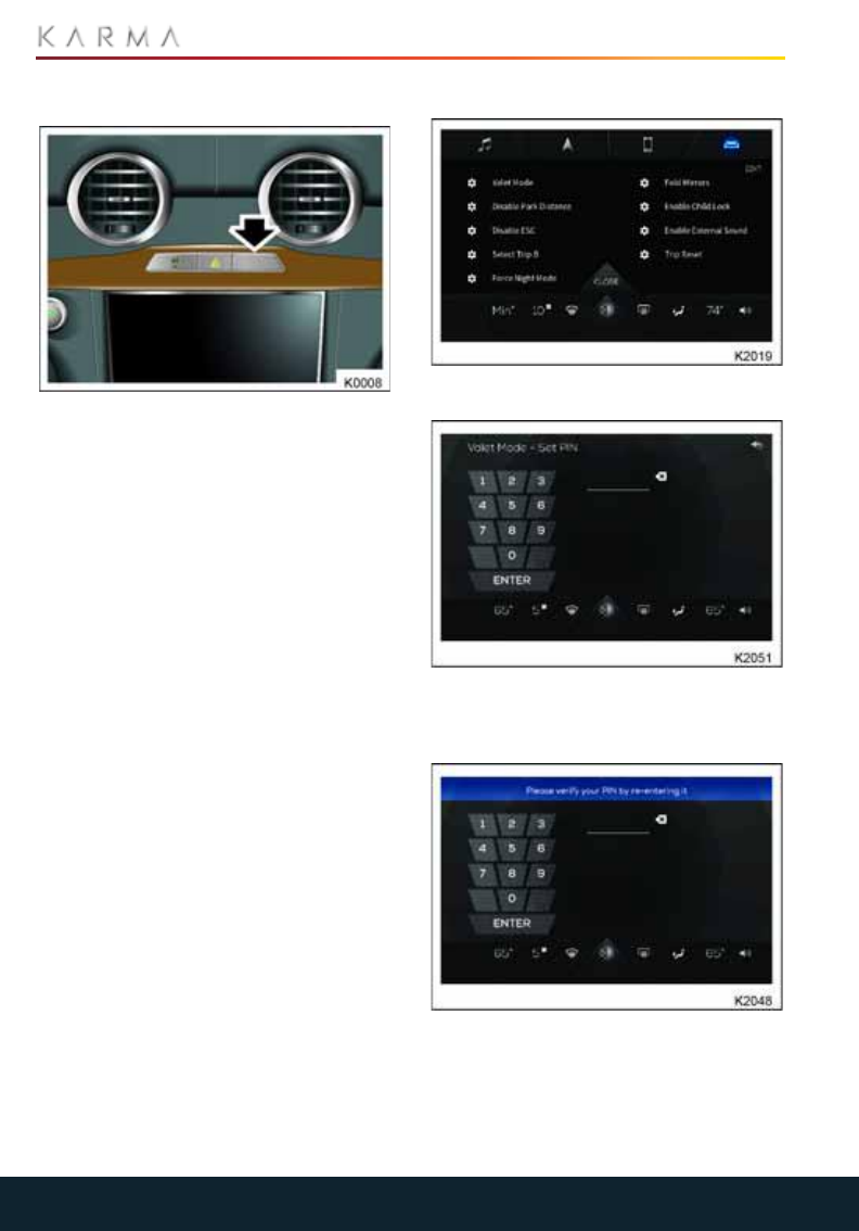
GLOVE COMPARTMENT
To open the glove compartment, press the
arrowed switch located above the
touchscreen.
Note: The glove compartment cannot be
opened when the vehicle is locked or when
Valet mode is enabled.
Note: When the interior lighting is
activated, the glove box light will also
illuminate.
VALET MODE
For your peace of mind, your Revero has a
Valet mode for those times that your
vehicle is parked by another person.
When Valet mode is active, access to the
trunk and glove compartment is restricted,
providing a secure location for storing
personal items.
The climate settings on the minibar and
rear backup camera are both active while
in Valet mode.
Valet mode can only be deactivated by
entering a PIN (Personal Identification
Number).
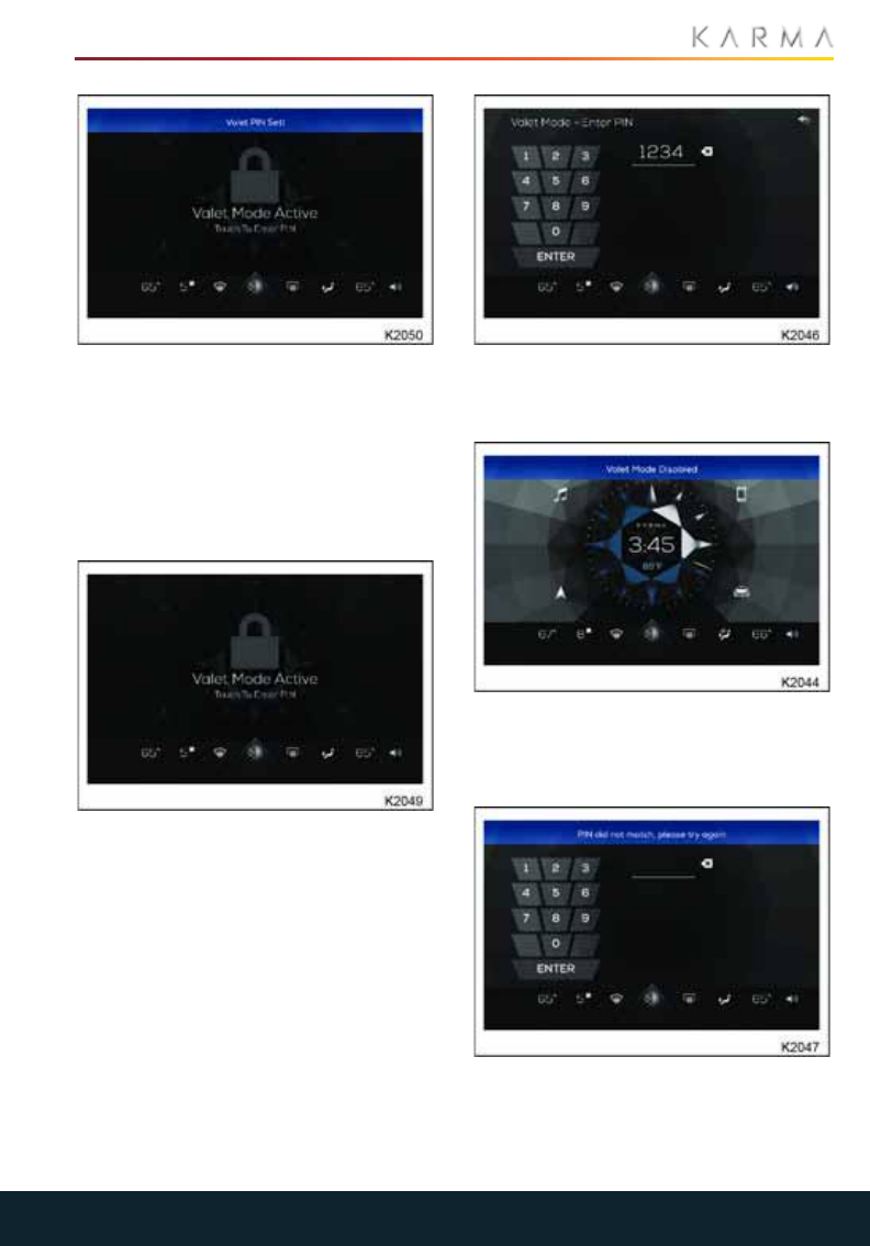
CREATING A PIN FOR VALET MODE:
1. From Favorites>MyKarma>ValetMode.
2. Pressing "Valet Mode" opens a
numerical keypad allowing four digits to
be entered.
3. After entering four digits press "Enter",
a mode bar will appear asking for you to
re-enter the same four digits.
23
GLOVE COMPARTMENT AND VALET MODE
4. Once entered the code is set and you
have entered into Valet mode.
Note: After 5 seconds the mode bar
disappears.
Note: Setting the Valet Mode PIN can be
performed at MyKarma>Settings>Driver.
ACTIVATING VALET MODE
1. From Favorites>MyKarma>Valet Mode.
Note: Activating Valet mode can be
done in MyKarma>Settings>Driver
Mode>Valet Mode.
2. Touch the screen and a numeric keypad
appears.
3. Enter the four digit pin code and press
"ENTER", the screen will display the
home screen.
Note: After 5 seconds the mode bar
disappears.
WRONG PIN ENTERED
If you enter the wrong PIN a mode bar will
appear displaying PIN did not match.
Please try again.

24
GLOVE COMPARTMENT AND VALET MODE
Entering the correct four digit PIN code and
the screen will display the home screen.
Note: After 5 seconds the mode bar
disappears.
Note: If no character is entered, or there is
no activity in 10 seconds, the system
returns to the locked screen.
Note: If Valet mode is active, and you can’t
remember or don’t know what the PIN is to
deactivate it, you will need to take the
vehicle to a Karma Service Provider who
will be able to reset the system.

25
OCCUPANT SAFETY
Occupant S afety
SEATS AND STEERING COLUMN
Correct Seating Position....................................................................................................................26
Steering Column Position..................................................................................................................26
Integrated Headrests..........................................................................................................................26
Electric Seats......................................................................................................................................... 27
Seat Heaters..........................................................................................................................................28
Driver’s Seat Memory.........................................................................................................................28
Easy Entry and Exit..............................................................................................................................29
SEAT BELTS
About Seat Belts...................................................................................................................................30
Seat Belt Safety....................................................................................................................................30
Wearing the Seat Belt.........................................................................................................................31
Wearing Seat Belts When Pregnant..............................................................................................31
Seat Belt Reminder..............................................................................................................................32
Seat Belt Tensioners............................................................................................................................32
Caring for Seat Belts...........................................................................................................................32
CHILD RESTRAINTS
Child Restraints.....................................................................................................................................34
Using a Non Latch Child Restraint.................................................................................................35
Using a Latch Child Restraint...........................................................................................................35
Upper Tether Strap Anchorages.....................................................................................................36
SUPPLEMENTARY RESTRAINT SYSTEM (SRS)
Location of Air Bags............................................................................................................................38
Important Information........................................................................................................................39
How the System Works.......................................................................................................................39
Deployment Effects.............................................................................................................................40
Obstruction of Air Bags......................................................................................................................40
Passenger Air Bag Deactivation......................................................................................................41
Air Bag Warning Labels......................................................................................................................41
SRS Warning Indicator........................................................................................................................41
Air Bag Service Information.............................................................................................................42
Vehicle Modifications...........................................................................................................................42
26
SEATS AND STEERING COLUMN
Seats and Steering Column
CORRECT SEATING POSITION
WARNING: Children under 4ft 5in
(1.35 m) tall or younger than 12 years
of age must be secured in a suitable child
restraint. See “Child Restraints” on
page 34.
To reduce the risk of injuries in the event of
an accident, observe the following:
•The driver and front passenger should
select a seat position that allows the
seat belt to be worn correctly, but is as
far away from the front air bags as
possible.
•Sit in an upright position with the base
of your spine as far back as possible
and the seatback reclined no more than
30 degrees.
•The position of the driver's seat must
allow the driver to drive the vehicle
safely. The distance from the driver's
seat to the pedals must be such that the
driver can fully depress the pedals. The
distance between the driver's chest and
the center of the air bag cover should,
ideally, be more than 10 inches
(254 mm). The driver's arms should be
slightly bent when holding the steering
wheel.
•Position the seatbelt so that it is mid-
way between your neck and your
shoulder. Fit the strap tightly across
your hips, not across your stomach.
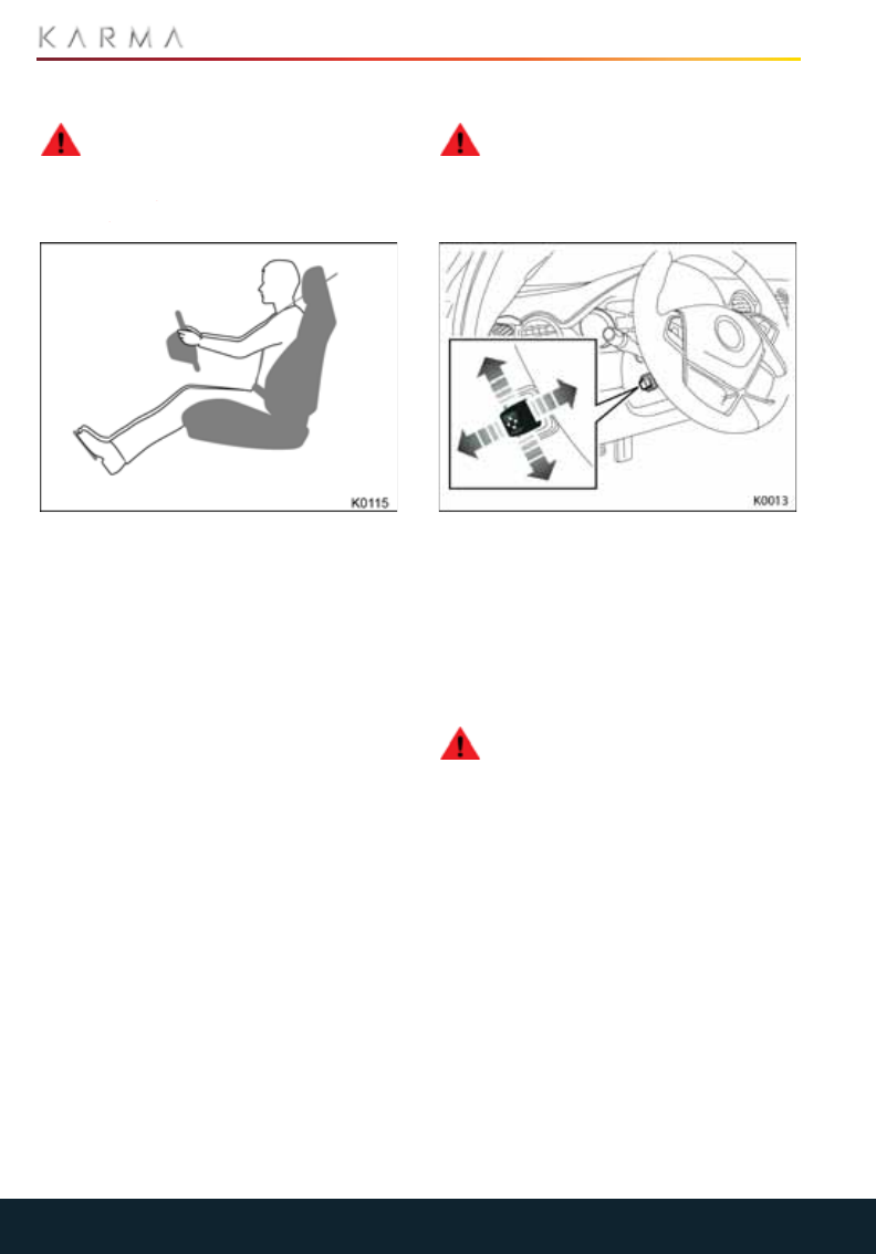
STEERING COLUMN POSITION
WARNING: Never adjust the steering
wheel position while the vehicle is in
motion. Doing so will reduce control of the
vehicle, and may cause unpredictable
steering movements.
With the vehicle stationary, adjust the
steering column to the desired driving
position.
INTEGRATED HEADRESTS
The front and rear seats provide
integrated head restraints in the seatback.
The head restraints are not adjustable.
WARNING: To minimize the risk of
neck injuries in the event of a collision,
the driver and front seat passenger should
adjust the seatback inclination such that
the headrest is in an upright position.
27
SEATS AND STEERING COLUMN
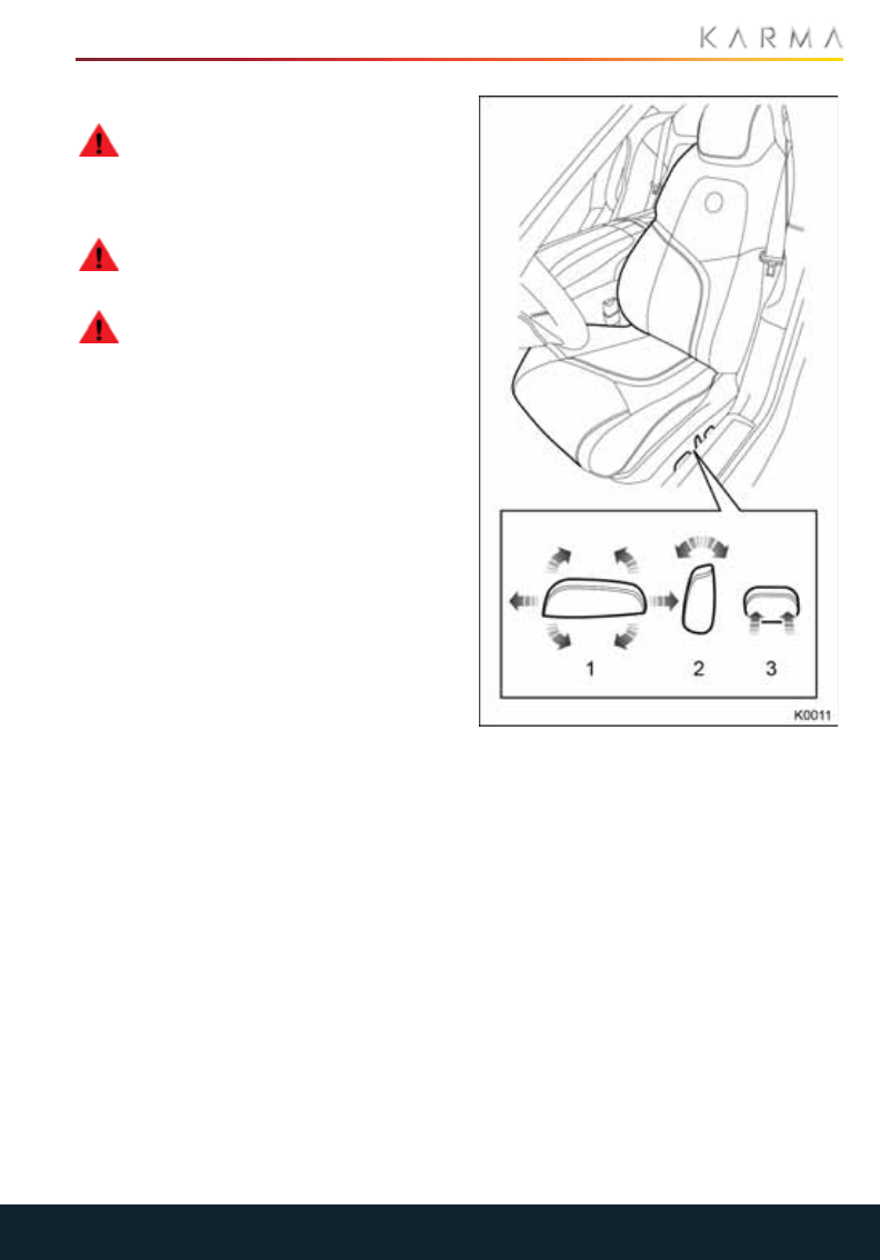
ELECTRIC SEATS
WARNING: Do not adjust any part of
a seat while the vehicle is in motion.
Vehicle movement may cause the seat to
suddenly shift, potentially causing injury or
loss of control.
WARNING: To prevent possible
injury, ensure that rear passengers
cannot become trapped as the seat moves.
WARNING: Sitting in a reclined
position when the vehicle is in motion
can be dangerous. Even when buckled up,
the seat belts cannot do their job. The
shoulder belt will not be against your body.
Instead, it will be in front of you. In a crash,
you could go into it, receiving neck or other
injuries. The lap belt could go up over your
abdomen and cause serious internal
injuries. For proper protection when the
vehicle is in motion, have the seatback
upright. Sit well back in the seat and wear
the seat belt properly.
1. Cushion tilt adjustment and
forward/backward adjustment
2. Backrest adjustment
3. Lumbar support
28
SEATS AND STEERING COLUMN
SEAT HEATERS
The seat heaters can be operated only
when the vehicle is in Drive mode. The seat
heaters will maintain a pre-determined
temperature according to the level
selected.
WARNING: If you cannot feel
temperature change or pain to the
skin, the seat heater may cause burns. To
reduce the risk of burns, people with such a
condition should use care when using the
seat heater, especially for long periods of
time. Do not place anything on the seat
that insulates against heat, such as a
blanket, cushion, cover, or similar item. This
may cause the seat heater to overheat. An
overheated seat heater may cause a burn
or may damage the seat.
The seats can be heated at three different
heat levels.
•Press once to operate at the highest
heat level. Three indicators will
illuminate.
•Press twice to operate at the medium
heat level. Two indicators will illuminate.
•Press a third time to operate at the
lowest heat level. A single indicator will
illuminate.
•Press a fourth time to turn off the
heaters.
Switching off the vehicle will automatically
turn off the seat heaters.
FRONT SEAT HEATERS
To turn on a front heated seat, touch
the appropriate heated seat icon on
the touchscreen.
REAR SEAT HEATERS
To turn on a rear heated seat press the
appropriate switch on the rear center
console switch pack.
DRIVER’S SEAT MEMORY
WARNING: Before activating the
seat memory, ensure that the area
immediately surrounding the seat is clear
of obstructions and that all occupants are
clear of moving parts.
WARNING: Never adjust the Settings
in the CIU while you are driving your
vehicle, even if you are temporarily
stopped. Wait until you are in a safe
location away from traffic, put the vehicle
in Park, and then access the Settings menu.
PROGRAMMABLE MEMORY
The vehicle can memorize three different
driver seat and steering column positions
through the “Settings” menu options in the
CIU.
When you unlock the vehicle, the seat and
steering column will automatically adjust to
the last used saved memory settings.
Adjust the seat and steering column to the
desired position, and then store the
program in the seat memory using the
touchscreen.

29
SEATS AND STEERING COLUMN
The Driver’s last used saved seat position
will be automatically recalled if the
following occurs:
•The car is in Park [P].
•A programmed key fob is present.
•The driver’s door goes from “open” to
“closed” (or the door is “open” and the
driver places vehicle in vehicle in
System Ready mode as if going to drive
the car).
•The Driver seat is not in the last saved
seat position location.
MEMORY SETTING PROCEDURE
1. Select [SETTINGS].
2. Select [INTERIOR].
3. Select the Memory/Seat Position
selection.
4. Adjust the driver seat and steering
wheel for Driver #1.
5. Touch the “Set” selection (under the
Primary Seat Memory selection).
Repeat the above steps for the Secondary
Seat Memory.
EASY ENTRY AND EXIT
Entry and exit mode provides automatic
movement of the steering column and
driver’s seat making it easier to enter or exit
the vehicle. Easy entry/exit is enabled and
settings can be programmed in the CIU
under the interior section located under
vehicle settings.
Note: This feature can be enabled or
disabled via the vehicle’s touchscreen.
ENTRY
When a programmed key fob is detected
outside the vehicle and the driver door
goes from “closed” to “open.” The steering
column and driver’s seat will return to the
previous position.
EXIT
When the vehicle is powered-down, the
steering column will move to the
uppermost tilt position and the driver’s
seat will move to the exit position.
Note: If the steering column or driver’s seat
is adjusted during entry or exit operation,
automatic movement will stop.

30
SEAT BELTS
Seat Belts
ABOUT SEAT BELTS
WARNING: Seat belts should be
worn by all occupants, for every
journey no matter how short. Failure to do
so greatly increases the risk of death or
serious injury in the event of an accident.
Seat belts and child restraint systems are
the most effective means of restraining
vehicle occupants from impact forces,
which, in turn, minimizes the danger of
injury from interior impacts and the effects
of whiplash. Therefore wearing a seat belt
is required by law in most states.
Both the driver and passenger seating
positions are equipped with three-point
inertia reel seat belts. Inertia reel belts are
tensioned automatically and allow
freedom of movement during normal
driving conditions.
The belt reel automatically locks,
preventing movement of occupants,
whenever your vehicle experiences the
force associated with hard acceleration,
braking, cornering or on impact in a
collision. The reel may also lock when
driving on steep hills or slopes.
Each of the Revero’s rear seating positions
is equipped with an Automatic Locking
Retractor (ALR), which can lock a child
restraint system when the webbing is
released after being completely pulled out.
The Revero’s right front seating position is
fitted with a cinch tongue which can be
used to lock the lap belt portion of the seat
belt assembly. Once the tongue is inserted
into the buckle, the lap portion will be
locked and cannot be extended by pulling
the webbing. It does not require inverting,
twisting or deforming of the webbing to
make this locking feature operate.
SEAT BELT SAFETY
WARNING: Children under 4ft 5in
(1.35 m) tall or younger than 12 years
of age must be secured in a suitable child
restraint. Follow the manufacturer's
instructions when installing child restraint
systems.
WARNING: A seat belt which is not
worn, is worn incorrectly, or has not
been engaged fully in the seat belt buckle,
cannot perform its intended function. To
avoid injuries, ensure that all vehicle
occupants wear their seat belt correctly at
all times.
WARNING: Seat belts are designed
to bear upon the bony structure of
the body, and should be worn low across
the pelvis, over the shoulder and across the
chest. Avoid wearing the lap section of the
belt across the abdominal area.
WARNING: Always adjust the belt to
remove slack. Seat belts worn too
loose can result in injuries because they
allow excessive forward movement in an
accident. Never wear the shoulder belt
under your arm or behind your back.
WARNING: Do not route the belt
across sharp edged or fragile objects
especially if these are on or in your clothing
The seat belt could be damaged and you
could be injured.
WARNING: Seat belts should not be
worn with any part of the strap
twisted.
WARNING: Each belt assembly must
only be used by one occupant; it is
dangerous to put a belt around a child
being carried on the occupant’s lap.
WARNING: It is essential that seat
belts that have been worn in an
accident are replaced, even if damage to
the assembly is not obvious. The belt
anchors must also be checked.
WARNING: No modifications or
additions should be made that
prevent the seat belt mechanism from
taking up slack, or that prevent the seat
belt being adjusted to remove slack. A slack
belt greatly reduces the level of occupant
protection.
WARNING: If any damage, wear,
cuts, defects, or impaired operation
are noted with the seat belts, the vehicle
should be taken to your Karma Service
Provider for immediate attention. Do not
31
SEAT BELTS
use the vehicle if the seat belts cannot be
operated correctly.
WARNING: Children can be seriously
injured or strangled if a shoulder belt
is wrapped around their neck and the seat
belt continues to tighten. Never leave
children unattended in a vehicle and never
allow children to play with the seat belt.
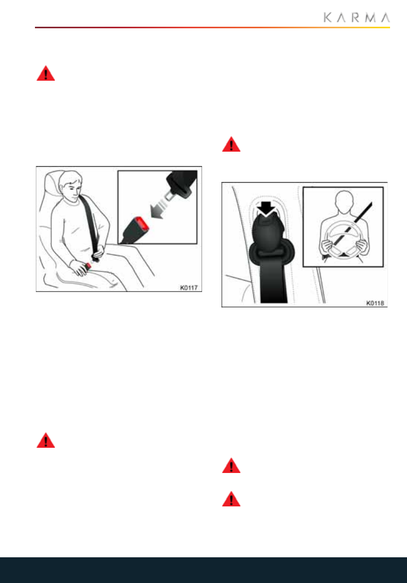
WEARING THE SEAT BELT
FASTENING THE SEAT BELT
1. Draw the belt out smoothly, ensuring
that the belt height, the seat position
and your position on the seat are
correct. The belt should lay flat across
the pelvis, chest and mid-point of the
collar bone between the neck and
shoulder.
2. With the belt correctly positioned, place
the metal tongue into the buckle
nearest to you. Press until a click is
heard.
RELEASING THE BELT
WARNING: Never allow more than
one child to wear the same seat belt.
A seat belt with two people in it cannot
properly restrain and could cause injury.
Never allow a child to wear the seat belt
with the shoulder belt behind their back. A
child who is not wearing the belt properly
can be seriously injured by the belt. The
shoulder belt should go over the shoulder
and across the chest.
Note: When releasing the belt, it is
advisable to hold it near the buckle before
pressing the release button. This will
prevent the belt from retracting too quickly.
To release the seat belt, press the red
button.
ADJUSTING THE HEIGHT OF THE
FRONT SHOULDER BELT
WARNING: After adjustment,
release the adjustment button and
then try to move the anchor point up or
down to ensure it is locked into position.
The height of the shoulder belt should be
adjusted so that the belt passes over the
center of your shoulder. The belt should be
away from your face and neck, but not
falling off your shoulder.
To adjust the height of the shoulder belt,
press the adjustment button and move the
shoulder belt anchor to the desired
position. Release the button to lock the
anchor in position.
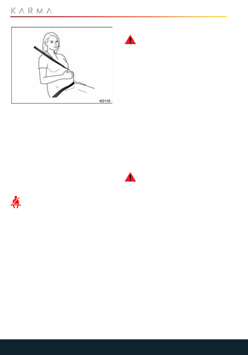
WEARING SEAT BELTS WHEN
PREGNANT
WARNING: Pregnant woman should
always wear seat belts to protect
themselves and their unborn child.
WARNING: Never place anything
between you and the seat belt to
cushion the impact in the event of an
accident.
32
SEAT BELTS
The lap portion of the belt should be worn
as low as possible across the hips, not the
waist. Position the diagonal part of the belt
between the breasts and to the side of the
abdomen. Ensure that the seat belt is not
slack or twisted.
If you have any concerns about wearing
seat belts, contact your doctor.
SEAT BELT REMINDER
The driver’s seat belt includes a buckle
sensor, to detect when the buckle is
latched.
If the driver’s seat belt is not fastened,
an indicator light on the DIS will
illuminate.
In addition, if the seat belt is unfastened
when the vehicle is in Drive mode and the
vehicle’s is moving at a speed greater than
5mph (8 km/h), an audible chime will sound
for 15 seconds as a belt reminder.
SEAT BELT TENSIONERS
WARNING: Once the seat belt
tensioners have been activated, they
must be replaced. After any collision,
always have the air bags, seat belt
assembly and any associated components
checked and, if necessary, replaced by a
Karma Service Provider.
The seat belts are equipped with
tensioners that activate in conjunction with
the air bags and provide additional
protection in the event of a severe frontal
impact on your vehicle.
The tensioners automatically retract the
seat belt, reducing any slack in both the lap
and diagonal portions of the belts.
Following an accident in which the
tensioners have been activated, the seat
belts continue to function as restraints and
must be worn if you drive your Revero.
CARING FOR SEAT BELTS
WARNING: Regularly check the
condition of all belts. Replace seat
belts if you notice any damage to the belt
webbing, fittings, retractor mechanisms or
buckles.
Three tests for checking seat belts:
1. With the seat belt fastened, give the
webbing nearest the buckle a quick pull.
The buckle should remain securely
locked.
2. With the belt unfastened, unreel the
webbing to its limit. Check that
unreeling is free from snags and visually
check the webbing for wear. Allow the
webbing to retract, checking that
retraction is smooth and complete.
3. With the webbing half unreeled, hold
the tongue plate and pull forward
quickly. The mechanism must lock
automatically and prevent further
unreeling.


34
CHILD RESTRAINTS
Child Restraint s
CHILD RESTRAINTS
WARNING: Your Revero is equipped
with an air bag system that has no
provision for switching off or deactivating
the front passenger air bag.
WARNING: Extreme hazard! Rear
facing child safety seats should
never be used in the front seat, or in the
path of any frontal air bag. Doing so
increases the risk of death or serious injury
when the air bag deploys. The best place
for a child is properly restrained in the rear
seats.
WARNING: Do not use a forward
facing child seat until a child is above
the minimum weight of 20 lb. (9 kg) and
able to sit up unaided. Up to the age of two,
a child's spine and neck are not sufficiently
developed to avoid injury in a frontal
impact.
WARNING: Do not allow a baby or
infant to be held or carried on the lap.
The force of a crash can increase effective
body weight by as much as thirty times,
making it impossible to hold onto the child.
At all times, children should be restrained in
age and size appropriate child seats to
reduce the risk of injury in a crash.
The seat belts installed on your Revero are
designed for adults and larger children. For
their safety, it is very important that all
infants and children under 12 are
restrained in a suitable child safety seat
appropriate to their age and size.
Only install a child seat that has been
approved for use in your Revero, and
ensure that the manufacturer's installation
instructions are followed exactly. Consult a
Karma Service Provider for a list of
approved child seats.
Note: The legislation which governs how
and where children should be carried when
traveling in a vehicle is subject to change. It
is the responsibility of the driver to comply
with all current laws and regulations.
CHILD RESTRAINTS FOR SMALL
CHILDREN AND BABIES
Child seats and restraint systems designed
for your Revero will be one of two types:
•Those secured in vehicle seats by the
seat belts.
•LATCH (Lower Anchors and Tether for
Children) type child restraints,
employing anchor bars built into the
rear seat frame.
All new and most older type child restraint
systems incorporate an upper tether strap
which can be attached to an anchorage
point on the vehicle.
CHILD RESTRAINTS FOR LARGER
CHILDREN
In a situation where a child is too large to fit
into a child safety seat, but is still too small
to safely fit the 3 point seat belt properly, a
booster seat is recommended for
maximum safety. Follow the
manufacturer’s installation instructions
exactly, then adjust the seat belt to suit.
Children typically require the use of a
booster seat appropriate to their age and
size, thereby enabling the seat belts to be
properly worn, reducing the risk of injury in
a crash.
35
CHILD RESTRAINTS
CHOOSING A CHILD RESTRAINT
Any child under 4ft 5in (1.35 m) tall or
younger than 12 years of age traveling in
the vehicle must be secured in the
appropriate safety restraint for their
weight (see chart below). Contact a Karma
Service Provider for advice.
USING A NON LATCH CHILD
RESTRAINT
Carefully follow the instructions provided
by the manufacturer of the restraint
system.
Make sure that a child falls into the correct
weight range for the seat. Avoid dressing a
child in bulky clothing and do not place any
objects between the child and the restraint
system.
Always use the appropriate child restraints
and adjust harnesses for every child, every
trip.
Ensure that you have removed all slack
from the vehicle’s seat belt.
Regularly check the fit of a child seat and
replace seats or harnesses that show signs
of wear.
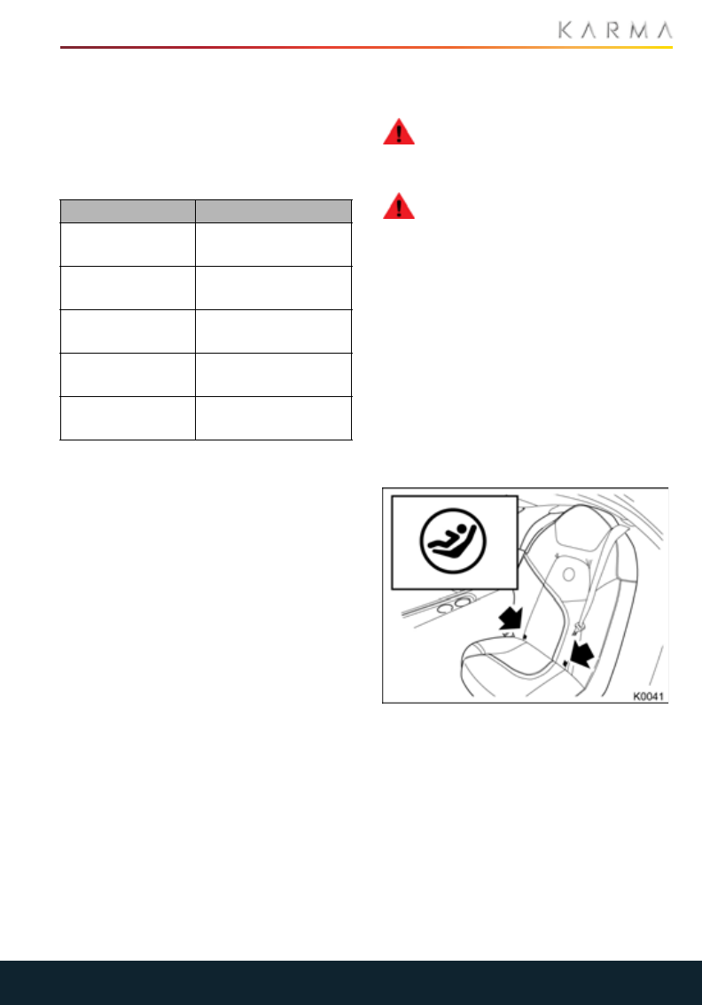
USING A LATCH CHILD
RESTRAINT
WARNING: If the restraint is not
correctly anchored, there is a
significant risk of injury to the child in the
event of a collision or emergency braking.
WARNING: Child restraint
anchorages are designed to
withstand only loads imposed by correctly
installed child restraints. Under no
circumstances are they to be used for adult
seat belts, harnesses or for attaching other
items to the vehicle. Doing so will greatly
increase the risk of serious injury or death
in the event of an accident.
Your Revero’s rear passenger seats are
equipped with the LATCH child restraint
anchorage system.
We recommend that you carefully follow
the instructions supplied by the
manufacturer when installing your LATCH
compatible child seats.
Lower LATCH anchorage points are
located between the seat back rest and
rear cushion on both sides of the vehicle as
indicated by the child seat identification
tab on the seat.
Category Weight
Category 0 Up to 22 lbs
(10 kg)
Category 0+s Up to 29 lbs
(13 kg)
Category I 20 to 40 lbs
(9 to 18 kg)
Category II 33 to 55 lbs
(15 to 25 kg)
Category III 48 to 80 lbs
(22 to 36 kg)
36
CHILD RESTRAINTS
To install your child seat with a LATCH
restraint system, slide the child seat until it
engages onto the anchor bars.
Test the security of the child seat, and
ensure it is correctly latched before seating
a child. Attempt to twist the child seat from
side to side and to pull it away from the
vehicle seat, then check that the anchors
are still securely in place.
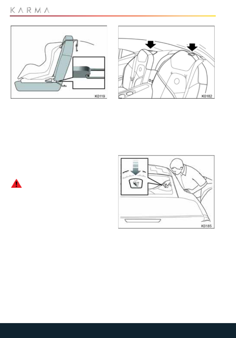
UPPER TETHER STRAP
ANCHORAGES
WARNING: Always check the upper
tether strap for damage or wear and
tear. A child could be seriously injured or
killed in a sudden stop or collision if the child
restraint upper tether strap is damaged or
not functioning properly.
Upper tether anchorages are provided at
each seating position equipped to accept
LATCH child restraints.
Note: Always ensure that if an upper tether
is provided, it is secured and tightened
properly, as this provides maximum
protection for a child.
Anchor points for the upper LATCH child
restraints are located behind the rear seat
headrests.
Note: Due to the restricted access in the
rear of your Revero, the easiest way to
actually view the upper anchorage point is
by standing outside the vehicle and looking
through the rear window.
With the rear door open, reach through the
door and remove the protective cover
located behind the headrest.

37
CHILD RESTRAINTS
Attach the tether strap hook to the tether
anchor point.
Tighten the tether strap according to the
child restraint manufacturer's instructions.
38
SUPPLEMENTARY RESTRAINT SYSTEM (SRS)
Supplementary Restraint System (SRS)
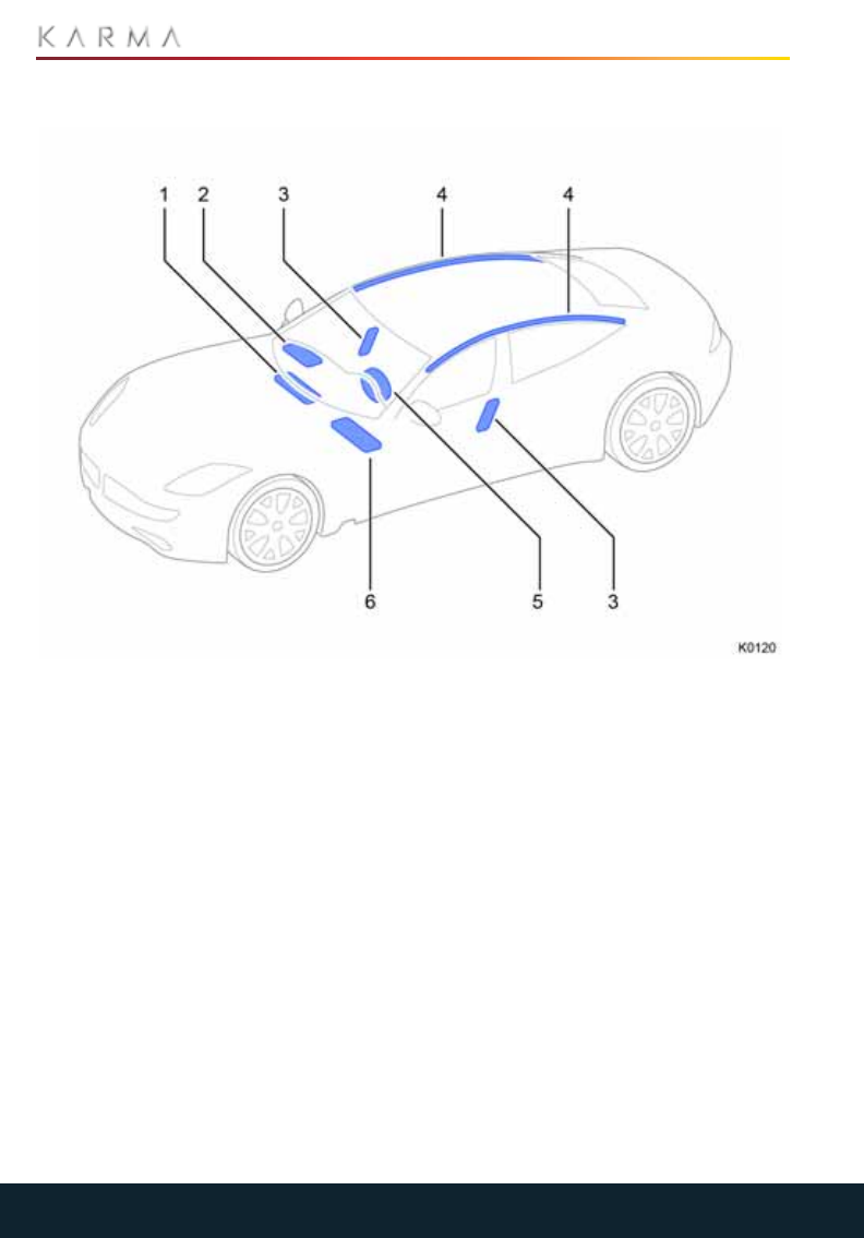
LOCATION OF AIR BAGS
1. Passenger’s knee air bag
2. Passenger’s front air bag
3. Side air bag
4. Curtain air bag
5. Driver’s air bag
6. Driver’s knee air bag
The exact location of the air bag modules
are indicated by the word AIR BAG on the
trim or a label sewn into the seat cover.

39
SUPPLEMENTARY RESTRAINT SYSTEM (SRS)
IMPORTANT INFORMATION
WARNING: Always remember that
the air bags are a Supplementary
Restraint System providing additional
protection in certain types of collision only
- they do not replace the need to wear a
seat belt. To reduce the risk of severe injury
or death in the event of a crash, all
occupants in all seating positions should
always wear their seat belt.
WARNING: Occupants not properly
restrained in designated seating
positions are at high risk of death or serious
injury in the event of air bag deployment.
WARNING: Do not use a child
restraint on a seat with an
operational air bag in front of it. There is a
risk of death or serious injury when the air
bag deploys.
WARNING: Because airbags inflate
with great force and faster than the
blink of an eye, anyone who is up against,
or very close to any airbag when it inflates
can be seriously injured or killed. Do not sit
unnecessarily close to any airbag, as you
would be if sitting on the edge of the seat or
leaning forward. Safety belts help keep you
in position before and during a crash.
Always wear a safety belt, even with
airbags. The driver should sit as far back as
possible while still maintaining control of
the vehicle.
HOW THE SYSTEM WORKS
WARNING: The air bags are a
Supplemental Restraint System
providing additional protection in certain
types of collisions only - they do not
replace the need to wear a seat belt.
Operation of the air bag system depends
on the rate at which your vehicle's
passenger compartment changes speed
as a result of a collision.
In the event of a collision, the air bag
control unit monitors the rate of
deceleration induced by the collision to
determine whether the air bags should be
deployed.
When deployed, air bags inflate instantly
with considerable force and are
accompanied by a loud noise. The inflated
bag, together with the seat belt restraint
system, limits the movement of the
occupants, thereby reducing the risk of
injury to the head and upper torso.
The air bag system is not designed to
operate as a result of:
•Rear collisions
•Minor front impacts
•Minor side impacts
•Heavy braking
•Driving over bumps or potholes
It follows, therefore, that significant
superficial damage can occur without the
air bags deploying or, conversely, that a
relatively small amount of structural
damage can cause the air bags to be
deployed.
KNEE AIR BAGS
The knee air bags are designed to work in
conjunction with the deployment of the
front air bags. When deployed, the knee air
bags limit the forward motion of the driver
or front passenger by restricting leg
movement, thereby positioning the
occupant so that the front air bags work
more effectively.
SIDE AIR BAGS
WARNING: Occupants should not
lean on or sleep against the door or
side windows in seating positions with
seat-mounted side impact airbags and/or
roof-rail airbags
WARNING: Ensure that a gap is
maintained between the side of the
vehicle and the torso, to enable
unobstructed inflation of the seat-
mounted side air bags.
WARNING: Do not use non-
approved seat covers or accessory
seat covers on a front seat as these will
prevent the side air bag from deploying
correctly in an accident. If in doubt, consult
a Karma Service Provider.

40
SUPPLEMENTARY RESTRAINT SYSTEM (SRS)
Side air bags are designed to protect the
thorax region of the torso and pelvis and
will only deploy in the event of a severe side
impact. They will not inflate as a result of
frontal or rear impacts only. The air bags
on the non-impacted side of the vehicle will
not be deployed.
CURTAIN AIR BAGS
WARNING: For the curtain air bags
to deploy correctly, the roof lining
and A post trim must be undamaged and
correctly installed. Any damaged air bag
component should be referred to a Karma
Service Provider for inspection.
Curtain air bags are designed to protect
the head in the event of a severe side
impact. They will not inflate as a result of
frontal or rear impacts alone.
DEPLOYMENT EFFECTS
WARNING: The powder released
during air bag deployment could
cause short-term breathing difficulties for
persons suffering from asthma or other
respiratory conditions. To prevent
breathing difficulties, leave the vehicle as
soon as possible if you are able or open a
window.
WARNING: Inflation and deflation of
the air bags take place
instantaneously and will not provide
protection against the effects of secondary
impacts that can occur during multiple
vehicle collisions.
WARNING: After an air bag has been
triggered, air bag parts are hot - do
not touch them. Have the air bags replaced
at a Karma Service Provider.
If the air bags are deployed, a bang will be
heard and a small amount of fine powder
may be released. The noise will not damage
your hearing and the powder does not
constitute a health hazard nor does it imply
that a fire has broken out.
The Supplementary Restraint System
(SRS) warning indicator will illuminate to
indicate that the system has been
deployed.
Air bag deployment slows down and
restricts the movement of the vehicle
occupant reducing the load on the body.
The air bags are in a de-pressurized state
following an accident.
SAFETY FEATURES
Along with the deployment of the air bags,
the following events will also occur to assist
you and any recovery personnel:
•The doors will unlock.
•The hazard lights will switch on.
•The interior lighting will switch on.
•The fuel supply to the engine will be
switched off.
•The high voltage supply will be switched
off.
•The HVAC system will be disabled.
The high voltage supply, the fuel supply to
the engine, and the cooling system to the
passenger compartment can be restored
by switching the vehicle OFF, allowing it to
go to "sleep," then entering Accessory
Mode.
OBSTRUCTION OF AIR BAGS
WARNING: Do not allow passengers
to obstruct the operation of the air
bags by placing parts of their body, or any
other objects in contact with, or in close
proximity to, an air bag module.
WARNING: Do not attach or position
items on an air bag cover which could
interfere with the inflation of the air bag or
be propelled inside the vehicle and injure
occupants.
41
SUPPLEMENTARY RESTRAINT SYSTEM (SRS)
PASSENGER AIR BAG
DEACTIVATION
WARNING: Your Revero is equipped
with an air bag system that has no
provision for switching off or deactivating
the front passenger air bag.
WARNING: Do not use seat
accessories that block the inflation
path of a seat-mounted side impact
airbag. Never secure anything to the roof
of a vehicle with roof-rail airbags by
routing a rope or tie-down through any
door or window opening. If you do, the path
of an inflating roof-rail airbag will be
blocked.
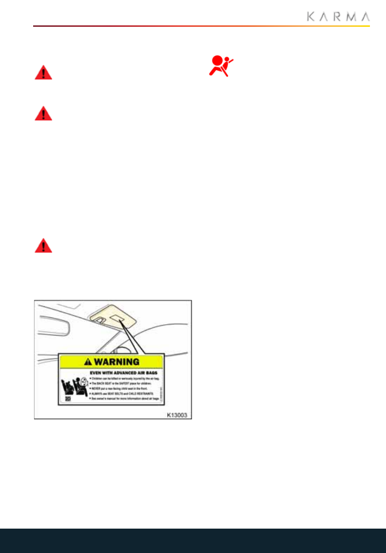
AIR BAG WARNING LABELS
Air bag warning information is printed on
the driver and passenger sun visors.
WARNING: Even with advanced air
bags children can be killed or
seriously injured by the airbag. The back
seat is the safest place for children. Never
put a rear-facing child seat in the front.
Always use seat belts and child restraints.
SRS WARNING INDICATOR
A warning indicator in the DIS alerts
you of any malfunction of the air
bag system.
The components of the system being
monitored include:
•SRS warning indicator
•Clock spring
•Air bag modules
•Seat belt tensioners (front seat belts)
•Air bag diagnostic control unit
•Crash sensors
•Air bag wiring harnesses
When the vehicle is in System Ready mode
or Drive mode, the air bag control unit
monitors the readiness of the system’s
electrical circuits.
The SRS warning lamp should illuminate in
the DIS for six seconds and then turn OFF,
indicating the system is operational and
ready. If the SRS warning lamp is
illuminated, a fault has been detected and
the air bag system is disabled.
Contact a Karma Service Provider if:
•The warning indicator fails to illuminate
when the vehicle is first put into
Accessory or Drive mode.
•The warning indicator fails to extinguish
within approximately six seconds after
the vehicle is put into Accessory or Drive
mode.
•The warning indicator illuminates while
your Revero is being driven.

42
SUPPLEMENTARY RESTRAINT SYSTEM (SRS)
AIR BAG SERVICE INFORMATION
WARNING: The disposal of used air
bag units is subject to stringent
regulations, and should only be handled by
a Karma Service Provider.
WARNING: If the airbag warning
light ever comes on and stays on, it
means that something may be wrong with
the airbag system. To help avoid injury to
yourself or others, have the vehicle
serviced right away.
For your safety, a Karma Service Provider,
who is familiar with your Revero, must
perform the following tasks:
•Removal, replacement, repair, or
modification, of any wiring or
component in the vicinity of air bag
system components, including the
steering wheel, steering column,
dashboard, DIS and roof lining.
•Modification to the front or side of your
Revero, including the bumper and
chassis.
In addition, always seek the assistance of a
Karma Service Provider if:
•An air bag inflates.
•A seat belt tensioner activates.
•The front or side of your Revero is
damaged, even if the air bag has not
inflated.
•Any part of an air bag module cover
shows signs of cracking or damage.
VEHICLE MODIFICATIONS
WARNING: Occupants with
disabilities which may require
modification of the vehicle must contact a
Karma Service Provider before any
modifications are made.

43
CONTROLS AND OPERATION
Controls an d Operation
INSTRUMENTS
Driver Information System (DIS) USA Specification................................................................45
Driver Information System (DIS) Canadian Specification.....................................................46
Indicator Icons.........................................................................................................................................47
Warning and Information Messages.............................................................................................49
WIPERS AND WASHERS
Wipers and Washers...........................................................................................................................50
EXTERIOR LIGHTING
Exterior Lighting.....................................................................................................................................51
Turn Signals............................................................................................................................................52
Hazard Warning Flashers..................................................................................................................52
POWER WINDOWS
Power Windows.....................................................................................................................................53
MIRRORS
Exterior Mirrors......................................................................................................................................54
Interior Rear View Mirror...................................................................................................................54
TOUCHSCREEN
Using the Touchscreen........................................................................................................................55
Overview..................................................................................................................................................56
Favorites...................................................................................................................................................57
Audio.........................................................................................................................................................59
Navigation................................................................................................................................................61
Phone........................................................................................................................................................63
Pairing a Phone.....................................................................................................................................64
Minibar......................................................................................................................................................65
CLIMATE CONTROL
Using the System..................................................................................................................................68
Ventilation .................................................................................................................................................71
Operating Notes.................................................................................................................................... 72
STARTING AND DRIVING
Starting the Vehicle.............................................................................................................................. 73
Type Approval.........................................................................................................................................74
Selecting a Propulsion Mode.............................................................................................................75
Driving Modes........................................................................................................................................ 76
BRAKES
General Information............................................................................................................................78

44
CONTROLS AND OPERATION
Anti-Lock Braking System (ABS).................................................................................................... 78
Regenerative Braking......................................................................................................................... 79
Parking Brake......................................................................................................................................... 79
ELECTRONIC STABILITY CONTROL
Electronic Stability Control (ESC)....................................................................................................81
CRUISE CONTROL
Cruise Control........................................................................................................................................82
EXTERIOR SOUND
Exterior Sound.......................................................................................................................................83
DRIVERS ASSISTANCE
Advanced Driver Assistance System (ADAS)............................................................................84
Lane Departure Warning (LDW) ....................................................................................................84
Forward Collision Warning (FCW) .................................................................................................85
PARKING AIDS
Park Distance Control (PDC)............................................................................................................86
Rear View Camera............................................................................................................................... 87
GARAGE DOOR OPENER
Homelink® Transmitter.......................................................................................................................88
Programming a Device.......................................................................................................................88
Entry Gate/Canadian Programming............................................................................................89
Information and Assistance .............................................................................................................89
ACCESSORY SOCKETS
Accessory Power Outlets...................................................................................................................90
USB Connections..................................................................................................................................90
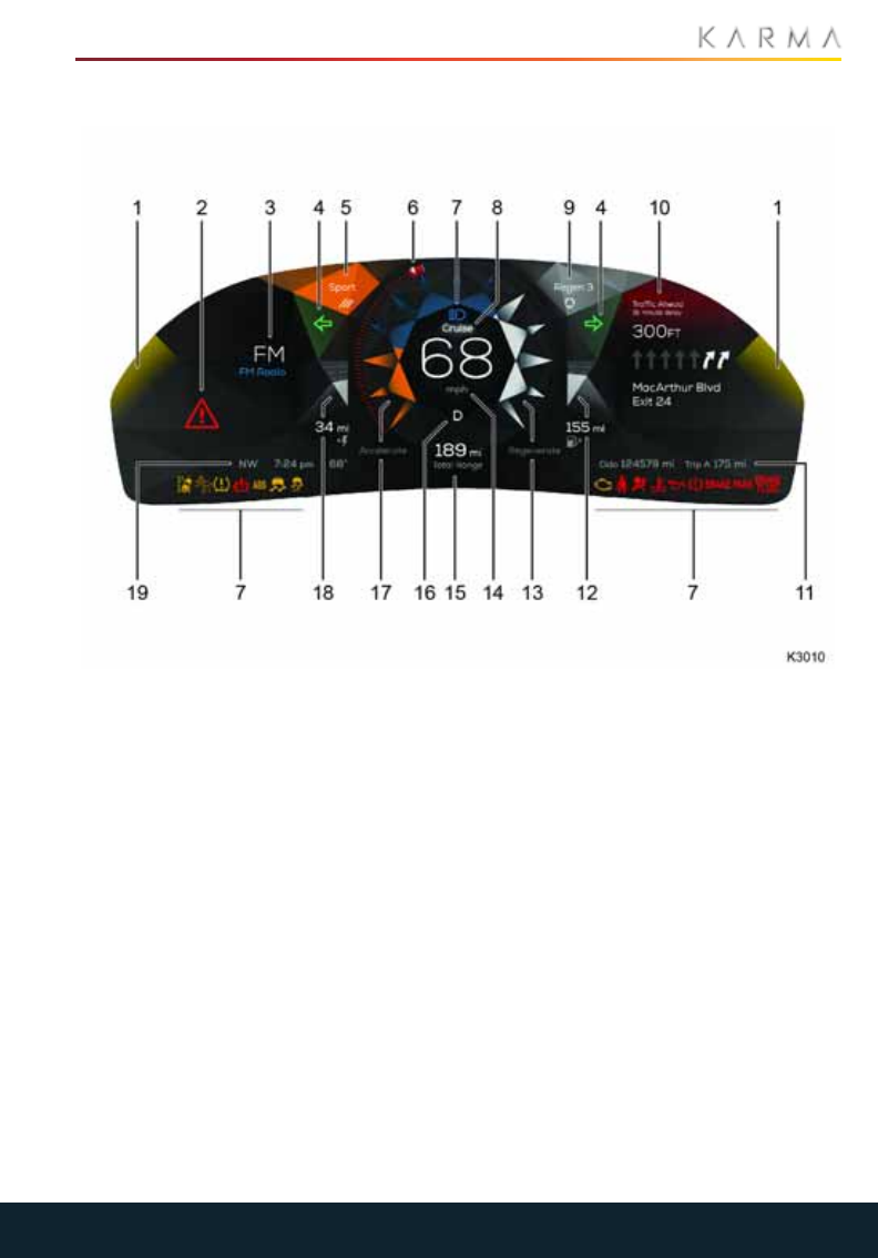
45
INSTRUMENTS
Instruments
DRIVER INFORMATION SYSTEM (DIS) USA SPECIFICATION
1. Lane departure warning (left/right)
2. Function indicator with description
3. Audio / Phone status
4. Turn signals (left/right)
5. Drive mode
6. Cruise control speed setting
7. Function indicators
8. Cruise control ON indicator
9. Regenerative braking setting
10. Navigation turn-by-turn
11. Odometer, Trip meter
12. Fuel range
13. Regenerative braking meter
14. Speed odometer
15. Total range
16. Gear status
17. Acceleration meter
18. Electric range
19. Compass, Time, Temperature
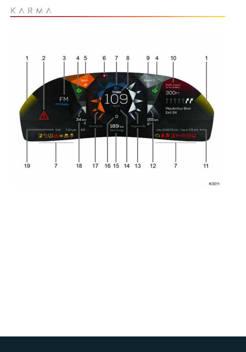
46
INSTRUMENTS
DRIVER INFORMATION SYSTEM (DIS) CANADIAN SPECIFICATION
1. Lane departure warning (left/right)
2. Function indicator with description
3. Audio / Phone status
4. Turn signals (left/right)
5. Drive mode
6. Cruise control speed setting
7. Function indicators
8. Cruise control ON indicator
9. Regenerative braking setting
10. Navigation turn-by-turn
11. Odometer, Trip meter
12. Fuel range
13. Regenerative braking meter
14. Speed odometer
15. Total range
16. Gear status
17. Acceleration meter
18. Electric range
19. Compass, Time, Temperature
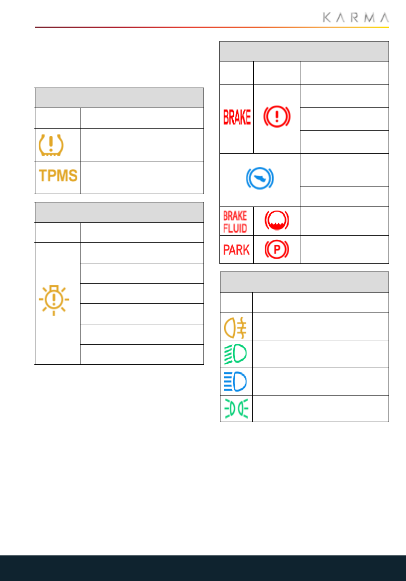
47
INSTRUMENTS
INDICATOR ICONS
The following indicator icons may be
displayed throughout the DIS during
normal driving conditions.
Tires
Icon Description
Check tire
Tire pressure monitoring
system function. Contact
Karma service provider.
Function check
Icon Description
Rear center brake light
High beam
Low beam
Day run lights
Marker light
Fog light
Brakes
Icon
(USA) (Canada) Description
Brake system
function
Left brake lamp
function
Right brake lamp
function
Calibration
required. Apply foot
and park brake
Press brake to start
Brake fluid level low
Park brake
Lamps
Icon Description
Rear fog lamp
Low/Dipped beam headlights
Head lamp high beam ON
Parking lamps ON
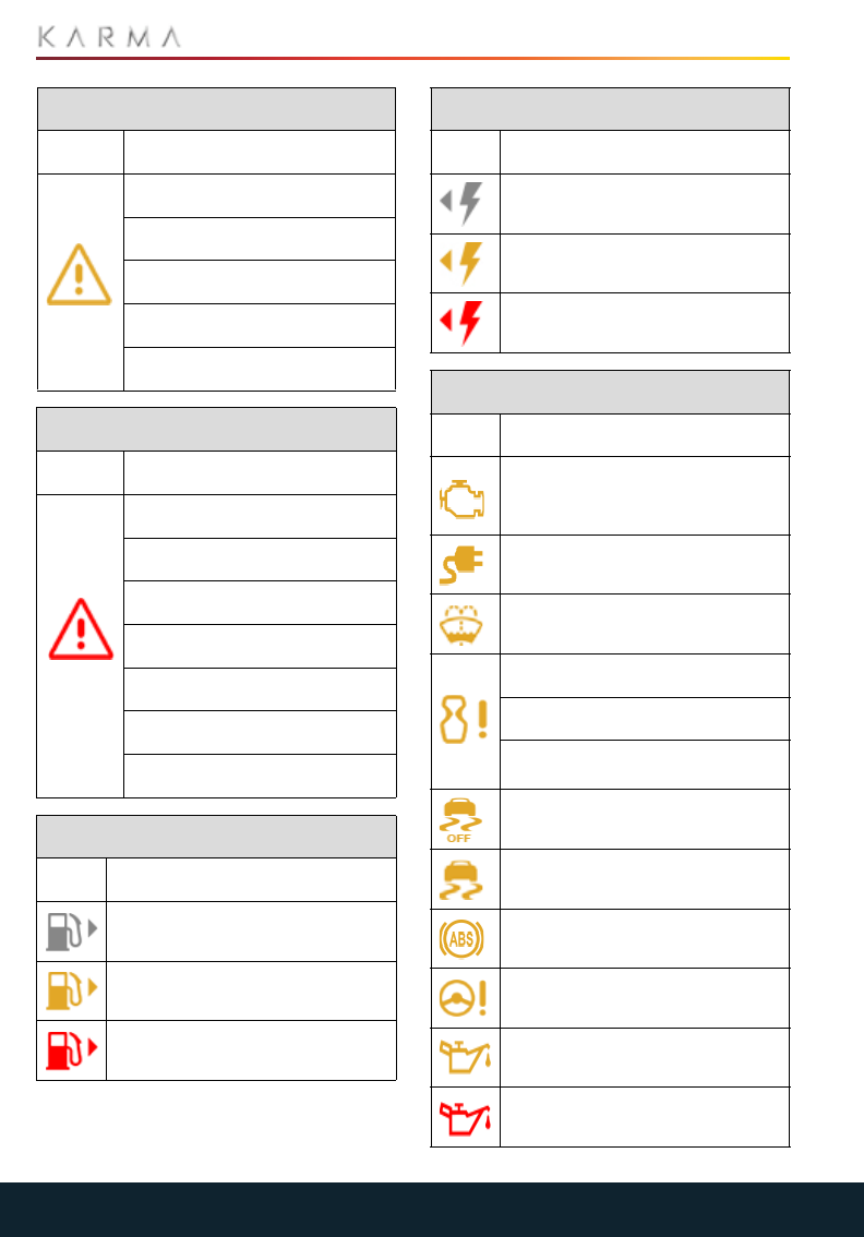
48
INSTRUMENTS
Hazards (yellow)
Icon Description
Powertrain function
Brake system function
Park sensor function
Accelerator pedal function
Onboard charger function
Hazards (red)
Icon Description
Emergency shut-down
Critical powertrain function
Performance limited
Gear selector function
Park gear lock function
Engine disabled
Genset function, EV range only
Fuel & Battery
Icon Description
Good fuel level
Low fuel level
Very low fuel level
Good charge level
Low charge level
Very low charge level
Misc
Icon Description
Check engine
Unplug vehicle to start
Windshield washer fluid low
Key fob not detected
Key fob not recognized
Key fob battery low. Replace
battery
Traction control function OFF
Traction control function
Anti-lock brake (ABS) function
Steering system function
Oil change due
Engine oil critically low
Fuel & Battery
Icon Description
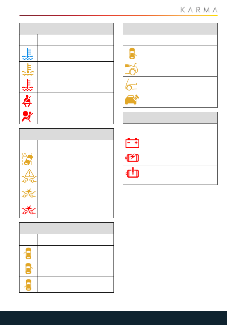
49
INSTRUMENTS
WARNING AND INFORMATION
MESSAGES
The lower left mid segment of the DIS is the
notification area that displays all
notification messages.
Engine is extremely cold and has
been disabled
Engine hot! Drive moderately
Engine overheated
Seat belts
Airbags
Departure-Collision
Icon Description
Lane departure warning system
function
Forward collision warning
system function
Forward collision warning
Forward collision warning
Door & Ajar events
Icon Description
Front left door ajar
Front right door ajar
Rear left door ajar
Misc
Icon Description
Rear right door ajar
Trunk ajar
Hood ajar
Check fuel cap/door
Battery
Icon Description
12 volt system function
High voltage battery state of
charge low
High voltage battery function
High voltage battery
temperature is low
Door & Ajar events
Icon Description
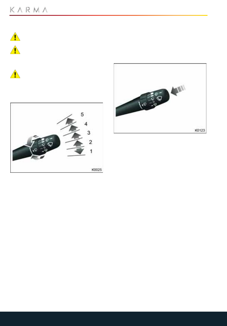
50
WIPERS AND WASHERS
Wipers and Washers
WIPERS AND WASHERS
CAUTION: Do not operate the wipers
on a dry windshield.
CAUTION: In freezing or very hot
temperatures, ensure that the wiper
blades are not frozen or adhered to the
windshield before operating.
CAUTION: In winter, remove any
snow or ice from the windshield, wiper
arms and blades before operating.
The wipers and washers are controlled by
the right-hand steering column lever.
With the vehicle in Accessory or Drive
mode, move the lever up or down to select
the required wiper mode.
1. Single wipe
2. Off
3. Intermittent wipe mode
4. Normal speed operation
5. High speed operation
INTERMITTENT WIPE
With the wiper control in position 3, rotate
the collar clockwise to increase the interval
between wipes. Rotate the collar
counterclockwise to decrease the interval
between wipes.
AUTOMATIC WIPER
The user can program the wipers to
function intermittently or automatically
through the CIU under Settings.
Position the rotary switch collar to the
sensitivity level to activate the Automatic
Wiper function. When the vehicle detects
moisture on the windshield, the wipers will
be automatically activated.
WINDSHIELD WASHER
Press and release the end of the lever to
operate the windshield washer.
HEAD LAMP WASHERS
The head lamp washers operate in
conjunction with every fifth operation of
the windshield washers.
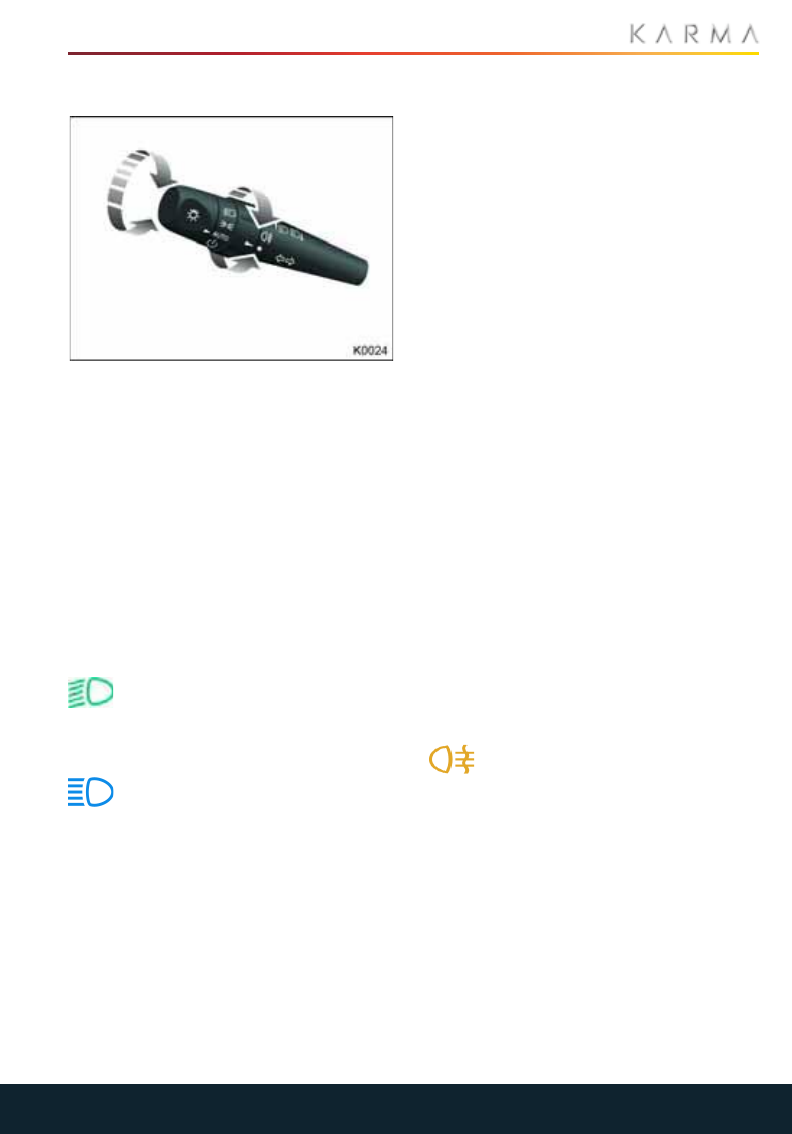
51
EXTERIOR LIGHTING
Exterior Lighting
EXTERIOR LIGHTING
The exterior lights are controlled by the
left-hand steering column lever.
Turn the rotary control on the end of the
lever to select the required lighting mode.
•OFF
•AUTO: the AUTO setting is the default
setting for head lamps and side lamps.
If the lights are turned off, or if the
ambient light falls below a defined level,
they will automatically be activated.
•Side lamps only
•Side lamps and head lamps
HEAD LAMP LOW BEAM
An indicator light on the DIS will
illuminate when the head lamp low
beams are operating.
HEAD LAMP HIGH BEAM
With the head lamps on, push the
column lever away from the steering
wheel to select high beam. An indicator
light on the DIS will illuminate when high
beam is selected.
To switch back to low beam, pull the lever
towards the steering wheel.
To flash the head lamps on high beam, pull
the lever fully towards the steering wheel
and release it.
HEAD LAMP COURTESY DELAY
The headlamp courtesy delay operates
whenever the vehicle is turned off and the
exterior lighting switch is in the AUTO
position. The head lamps will remain
illuminated for up to two minutes.
Note: The head lamp courtesy delay
settings can be configured to your personal
preference via the touchscreen.
The courtesy delay may be canceled at any
time by either selecting Accessory mode or
turning the exterior lighting switch to the
OFF position.
APPROACH LIGHTING
If the exterior lighting switch is in the AUTO
position, the head lamps will illuminate
when the vehicle is unlocked using the key
fob.
Note: The approach lighting setting can be
configured to your personal preference via
the touchscreen.
DAYTIME RUNNING LAMPS
In certain markets, the side lamps, license
plate lamps and head lamp low beams will
automatically illuminate when the vehicle is
in Drive mode and the exterior lights switch
is in the off position.
Note: The DIS illumination remains off.
REAR FOG LAMPS
With the headlights on, rotate and release
the collar on the lever to turn the rear fog
lamps on.
An indicator illuminates on the DIS
when the fog lights are operating.
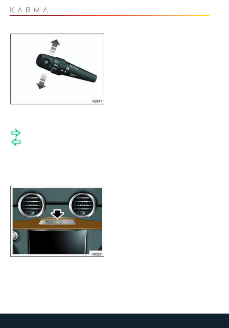
52
EXTERIOR LIGHTING
TURN SIGNALS
With the vehicle in Accessory or Drive
mode, move the lever up or down to
operate the turn signals.
A left or right indicator light on the
DIS will flash when the direction
indicator lamps are operating.
When the lever is held momentarily
up or down against spring pressure and
then released, the turn signals will flash to
indicate a lane change.
HAZARD WARNING FLASHERS
Press the arrowed switch to operate. The
front and rear turn signals will flash along
with the turn signal indicator lights on the
DIS. If the vehicle is in System Ready mode,
the flashers will continue to operate. Use in
an emergency to warn other road users
that your vehicle is disabled.
Press the switch again to switch off the
hazard flashers.
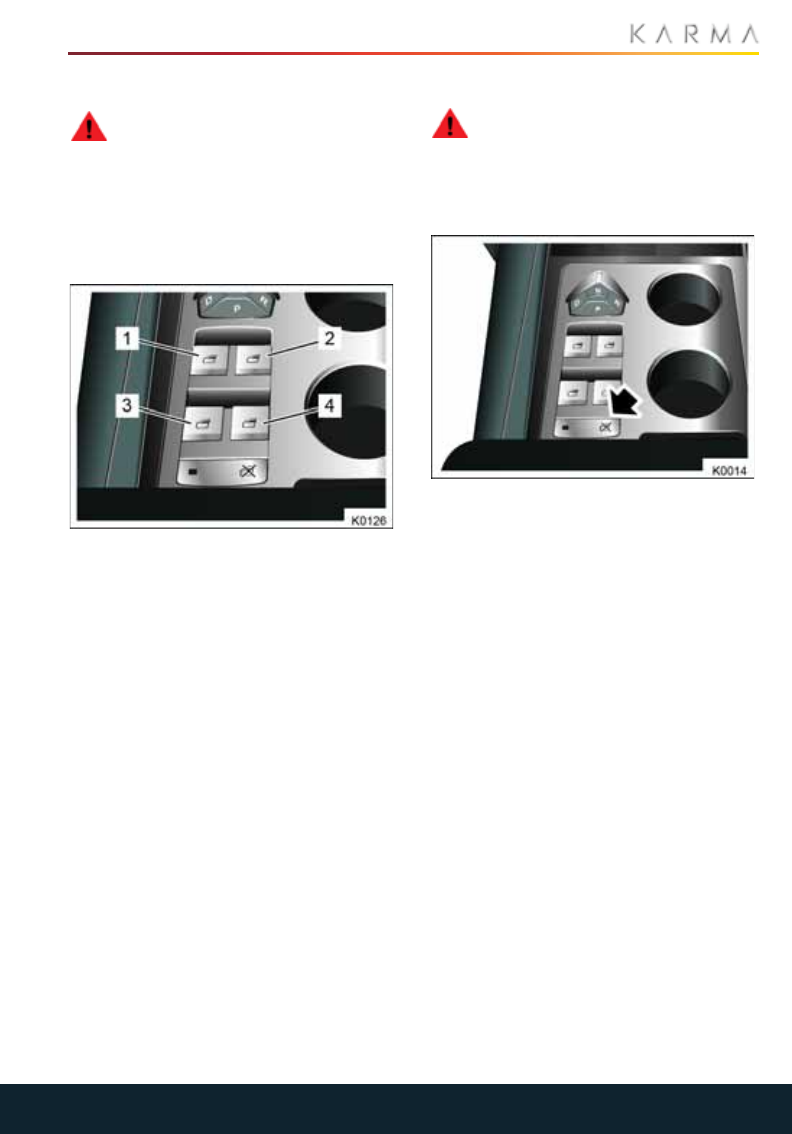
53
POWER WINDOWS
Power Windows
POWER WINDOWS
WARNING: Closing power windows
on fingers, hands or other vulnerable
parts of the body may result in serious
injury. Ensure that your passengers are
familiar with the window controls and
aware of the potential dangers.
The power windows can be operated in
Accessory or Drive modes.
1. Left-hand front window
2. Right-hand front window
3. Left-hand rear window
4. Right-hand rear window
Press and hold the front of the respective
switch to lower the window. Pull and hold
the front of the respective switch to raise
the window. Release the switch at any
point to stop window movement.
EXPRESS WINDOW OPERATION
All of the windows can be fully opened or
closed with a single press of the switch.
Firmly press or lift (and then release) the
front of the switch, to open or close the
window. Window movement can be
stopped by pressing the switch again.
REAR WINDOW OPERATION
The rear windows can be operated from
the switches on the rear center console if
the rear window inhibit switch has not been
activated.
REAR WINDOW INHIBIT
WARNING: If children are carried in
the rear seats, the rear window
inhibit switch should be used to prevent
operation of the windows. If the windows
are operated by young children there is a
risk of death or serious injury.
To disable the rear window switches, press
the rear window inhibit switch (arrowed). A
light on the switch will illuminate when the
rear windows switches are inhibited.
Note: Inhibiting the rear window switches
also activates the child safety locks.
Press the switch again to cancel.
Note: The windows can still be operated
using the switches located in the front of
the vehicle.
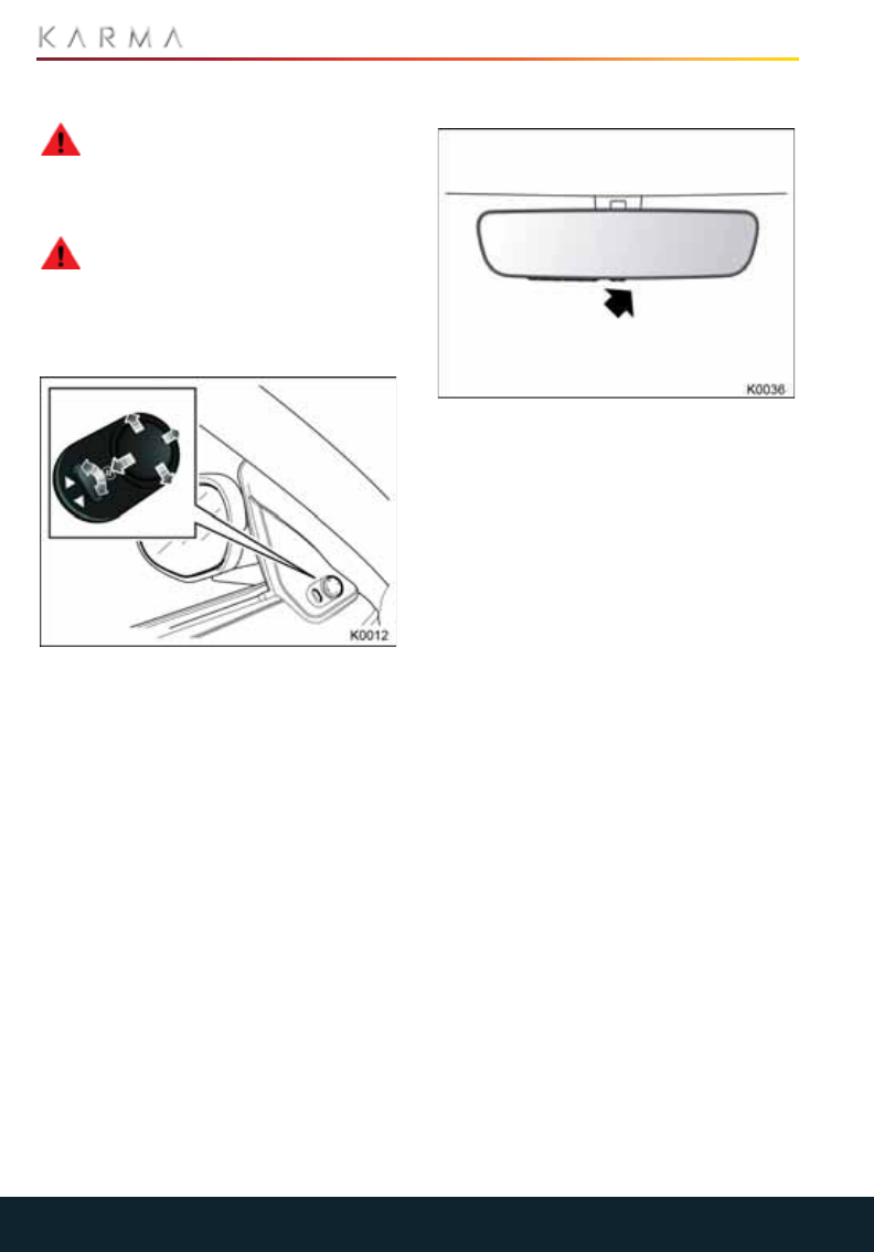
54
MIRRORS
Mirrors
EXTERIOR MIRRORS
WARNING: Depending on the type of
mirror glass installed on your Revero,
distances may be difficult to judge
accurately. Objects viewed in the mirror
may be closer than they appear.
WARNING: Never adjust the Settings
in the CIU while you are driving your
vehicle, even if you are temporarily
stopped. Wait until you are in a safe
location away from traffic, put the vehicle
in Park, and then access the Settings menu.
To adjust the exterior mirror position:
1. Select the required mirror using the
mirror selector switch.
2. Use the mirror control to set the desired
mirror position.
FOLDING SIDE MIRRORS
Auto Fold-In: lock the car from either the
key FOB or the master door lock switch.
When the doors are closed, the mirrors will
automatically fold-in.
Auto Fold-Out: Unlock the doors from
either they key FOB or Passive Unlock
feature. The mirrors will automatically
foldout.
Note: Automatic folding and unfolding of
the exterior mirrors, when the vehicle is
locked or unlocked, can be configured to
your personal preference via the
touchscreen.
INTERIOR REAR VIEW MIRROR
The rear view mirror will automatically dim
in proportion to the level of glare detected
from a following vehicle’s headlights.
If desired, this feature can be manually
switched off. An indicator light (arrowed)
will illuminate when the feature is active.
Note: If the rear window is obscured, or the
light falling on the mirror is otherwise
obstructed, the automatic dimming may
not operate correctly.

55
TOUCHSCREEN
Touchscreen
USING THE TOUCHSCREEN
CAUTION: To ensure that the
touchscreen continues to operate
correctly, basic care points are listed
below.
•Clean ONLY with a lightly moistened
soft cloth.
•Do not use chemical agents, or
domestic cleaners, to clean any part of
the touchscreen, or around it.
•Do not allow any sharp, hard or
abrasive objects to come in contact with
the touchscreen.
•Where possible, try to park the vehicle
so as to avoid exposing the touchscreen
to direct sun light for long periods.
WARNING: Only operate, adjust or
view the touchscreen when it is safe
to do so. If necessary, stop the vehicle to
make changes, or safely operate features
of the touchscreen system.
The touchscreen can be operated
whenever the vehicle recognizes a key fob
within the vehicle.
Note: A short, light press is sufficient to
operate functions. Do not use excessive
pressure.
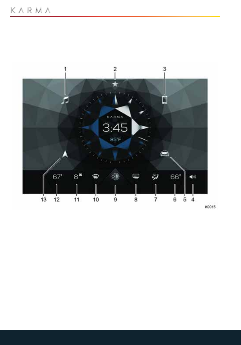
56
TOUCHSCREEN
OVERVIEW
The Karma home touchscreen interface
offers many features.
Touch the desired icon on the home screen
to access the desired feature. When active,
the icon will turn blue.
Note: Apple® CarPlay and Android Auto
coming soon.
1. Audio
2. Favorites
3. Phone
4. Volume
5. My Karma
6. Temperature passenger side
7. Ventilation
8. Rear window defroster
9. Climate control
10. Windshield defroster
11. Fan speed
12. Temperature driver side
13. Navigation
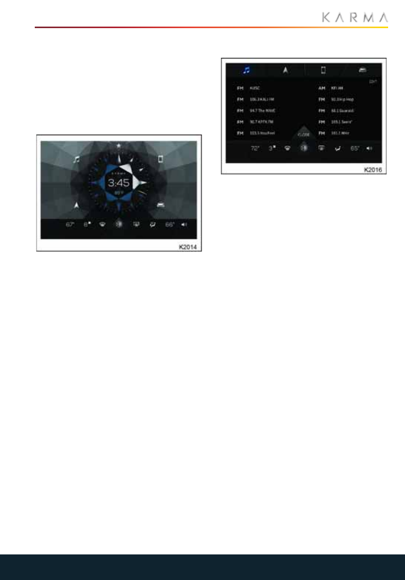
57
TOUCHSCREEN
FAVORITES
The Favorites Menu is located at the top of
the infotainment display screen. Touching
the star icon provides access to four
categories of programmed favorites
(audio, navigation, phone, and My Karma),
allowing for quicker navigation through
your most-used items.
FAVORITE ACCESS
Access Favorites by touching the star at
the top of the display.
To access the favorites lists, touch one of
the four quick access category tabs located
at the top of the favorites display screen:
•Audio
•Navigation
•Phone
•My Karma
AUDIO
Favorite Audio compiles your favorite
selections from all available inputs,
including FM, AM, Bluetooth and USB. If a
favorite is located on a disconnected media
device, the display will be grayed and you
will not be able to select it.
To delete favorites:
1. Press the EDIT text in the upper right
hand corner.
2. Red X's will appear on the list.
3. Press the X next to the item to be
deleted.
To add a selection to the audio favorites
list:
1. Touch the audio icon from the main
screen.
2. Select the audio source, and scroll
through the choices.
3. When the desired selection is
highlighted, touch the star icon next to
the selection to save it to favorites.
4. To remove a selection, just touch the
star icon again.
If choosing selections from a connected
media device, the device must be
connected to choose it from the favorites
list. Up to 10 selections can be saved to the
audio favorites list.
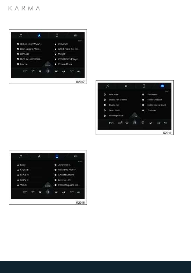
58
TOUCHSCREEN
NAVIGATION
Favorite Navigation allows quick and easy
access to frequently visited destinations.
To add a location to the favorites list:
1. Touch the Navigation icon from the
main screen,
2. Touch the Where to?
3. Up to 10 destinations can be added to
the favorites list.
4. Touch Go to begin navigation
PHONE
Favorite Phone accesses the contact list
from a connected mobile device.
To add a contact to favorites:
1. Touch the phone icon.
2. Select Contacts.
3. Scroll through the list until the desired
contact is highlighted.
4. Touch the star next to the number to
save it to the favorites list.
5. To remove a contact, touch the star icon
again.
6. If a contact has more than one number
available (such as mobile and home),
either number can be selected as a
favorite.
Up to 10 contacts can be saved to the
favorites list.
MY KARMA
Favorite My Karma is a place to find saved
systems configuration settings. Actions
available from this screen include:
•Quick activation of Valet Mode.
•Automatic Lock settings configuration.
•Seat position memory configuration.
There are 10 options available in the
favorites list which were pre-set at the
factory. These options cannot be edited or
removed from the My Karma favorites list.
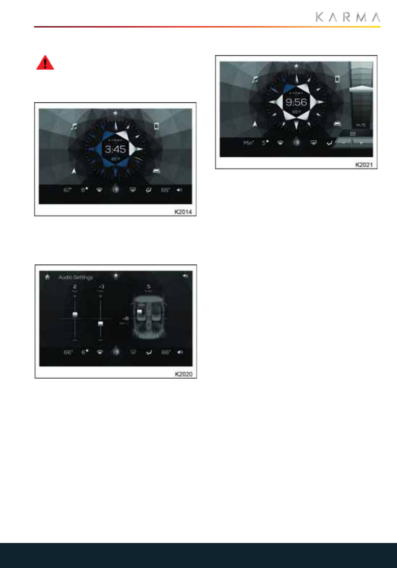
59
TOUCHSCREEN
AUDIO
WARNING: For safety reasons,
ensure that you do not become
distracted from the task of driving, through
use of any of these systems.
The Revero audio system includes AM/FM
radio, with the ability to connect external
media devices via Bluetooth or USB.
To access the audio system settings:
1. Touch the music note icon on the main
display screen.
2. Touch the Settings icon in the upper
right corner of the main audio display
screen.
3. Adjust the desired function.
VOLUME CONTROL
1. Press the speaker icon at the bottom
right corner of the main display to bring
up the volume controls.
2. Press the desired level to move the
volume indicator to that level, and
adjust the volume accordingly.
3. Press the Mute icon to mute the sound
(icon will turn red);
4. Press the mute icon again to return to
the previous volume.
5. The volume display will disappear if left
untouched for five seconds.

60
TOUCHSCREEN
SELECT A SOURCE
To select an audio source:
1. Touch the music note icon from the
main display screen,
2. Touch the Select Source tab at the top
of the audio screen.
3. Choose from the following options:
From here you can select:
FM /AM radio
• Brings up the station selection screen.
Favorites
•Brings up programmed list of favorites.
Bluetooth / USB
•Brings up the menu for the connected
device.
CHANGING STATIONS
There are two methods for changing the
radio station:
• + or - of tune function.
•The up and down arrows of the seek
function.
From the radio screen, the user can:
•Touch the star to the right of the radio
station listing to add it to the favorites
list.
•Touch the Select Source button to
change the audio source.
•Touch the Home icon to access other
features within the infotainment
system. The audio will continue to play
unless turned off.
Note: Selecting Bluetooth or USB requires
that compatible device be connected to the
infotainment system.
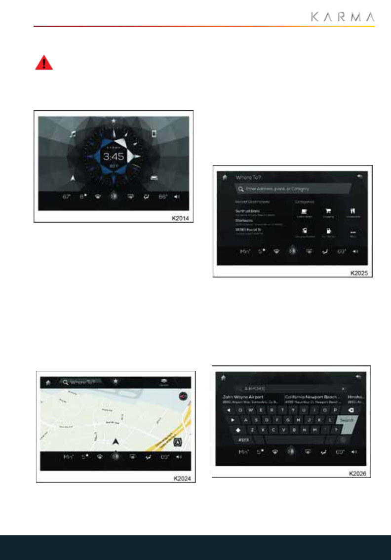
61
TOUCHSCREEN
NAVIGATION
WARNING: Be careful when
operating the navigation system.
Looking away from the road can lead to a
serious or fatal accident. Read the safety
instructions in the Owners Manual.
The Navigation feature offers turn-by-turn
navigation assistance, as well as pre-
programmed Points of Interest (POI) such
as restaurants and gas stations.
To access navigation:
1. Select the navigation icon from the
main display screen.
2. Touch the Options icon at the top right
of the display to configure the
navigation system preferences.
3. Touch the Where to? tab to enter the
desired destination, or touch the star
icon to select from the list of favorites.
When the Navigation panel is accessed, the
screen displays a map with an indicator
referencing the current position of the
vehicle.
Touch the icon at the bottom right of the
display to toggle between centering the
vehicle's position on the map, or showing
the entire route.
The top of the display contains:
•Where to? tab
•Favorites menu
•Options menu
•Compass (top right of map)
Touch the Where to? tab at the top of the
navigation display to access the
destination screen. This screen displays
options for:
•Manual address/place/category entry
•Recent destinations list
•Pre-programmed POI list
Manual Destination Entry
1. From the Navigation screen, touch the
Where to? button.
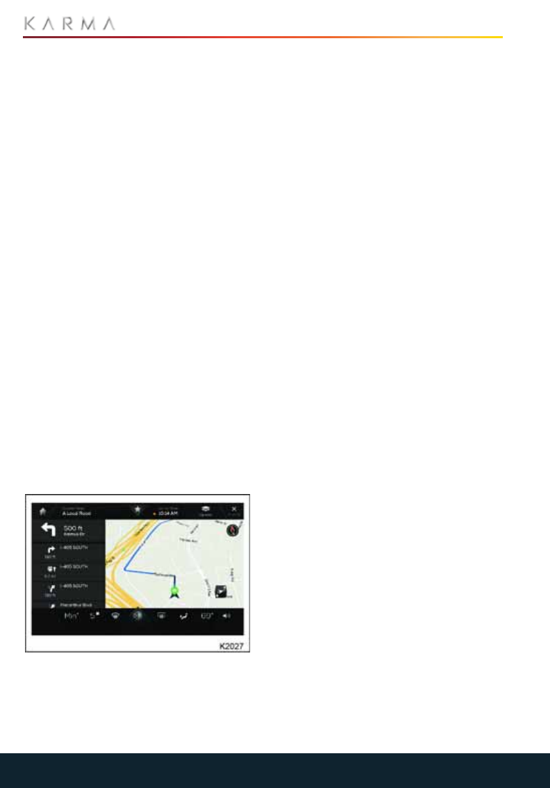
62
TOUCHSCREEN
2. Touch the Search box to bring up the
on-screen keypad.
3. Type the address, place name or
category (such as restaurants or
hotels).
4. If there is more than one destination
that matches your search, touch the
desired option.
5. Press Go to begin navigation.
Favorite Destination Entry
1. From top of the Navigation screen,
touch the star icon.
2. Select a location from the favorites list.
3. Touch the desired location, then press
Go to begin navigation.
Recent Destinations/POI Entry
1. From the Navigation screen, touch the
Where to? button.
2. For recent destinations: Below the
search box, there will be a list of recent
destinations. Scroll through this list to
find the desired destination.
3. For POI: Scroll through the POI
categories on the right side of the
screen. Choose the desired category,
then scroll through the list of
destinations.
4. Touch the desired destination, then
press Go to begin navigation.
Navigation Screen
Once a destination has been selected,
press Go to begin navigation. The
navigation screen will display turn-by-turn
directions on the left, and a map view of the
route on the right.
While the navigation screen is active, the
user can:
•Touch the icon at the bottom of the
screen to toggle between centered and
whole route views.
•Touch the Options menu to display
traffic conditions and set navigation
parameters (such as avoiding toll
roads).
•Touch the button in the upper right
hand corner to cancel the current
navigational assistance.
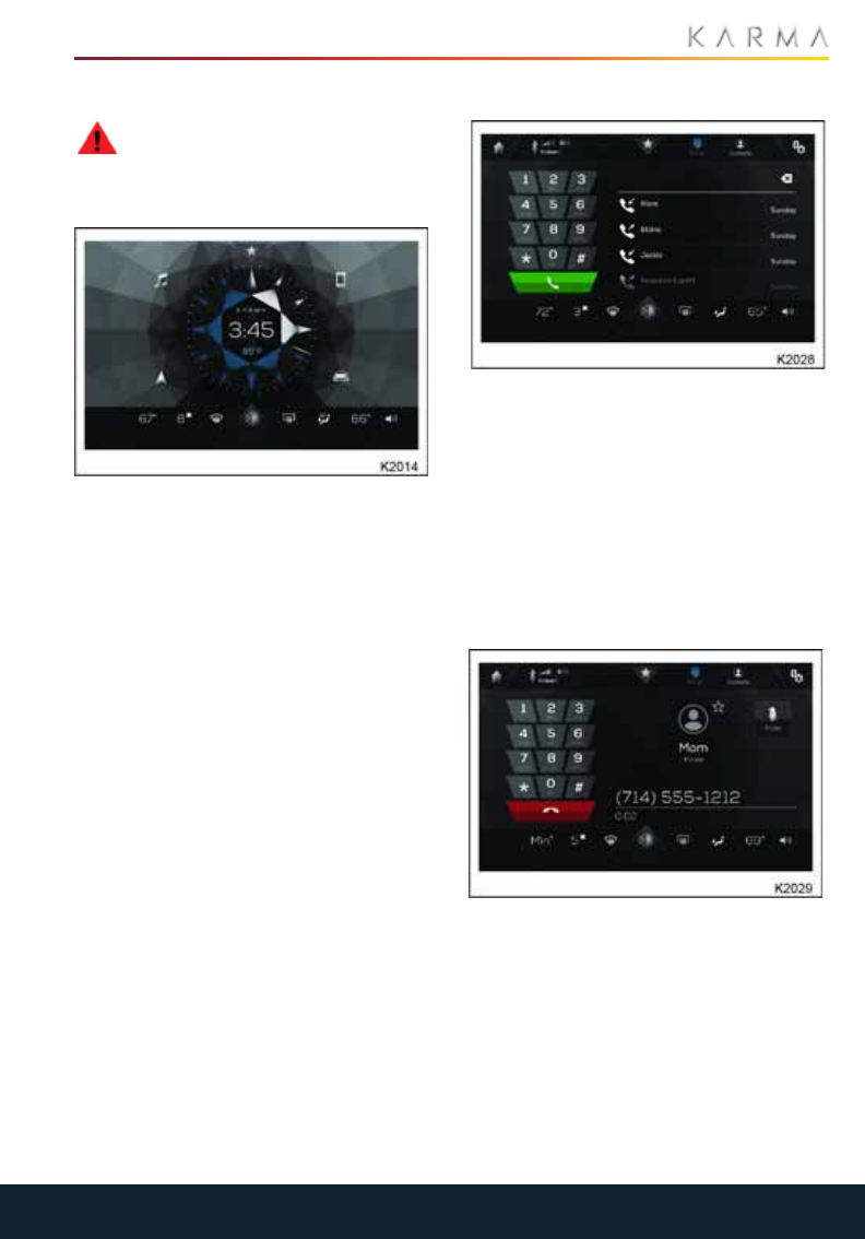
63
TOUCHSCREEN
PHONE
WARNING: For safety reasons,
ensure that you do not become
distracted from the task of driving, through
use of any of these systems.
To utilize the phone feature a mobile phone
must be connected to the system via
Bluetooth (see Pairing a Phone). Once
there is a paired phone in the vehicle, touch
the phone icon on the main display screen
to access the controls. Touching the phone
icon pulls up the main phone display,
including the keypad dialer and call history.
At the top of the display, information from
the connected phone is displayed, as well
as the favorites menu. Use the Dialer tab to
bring up the keypad, or the Contacts tab to
access the contact list. The top right corner
of the display contains the settings menu.
KEYPAD DIALER
To make a call using the keypad:
1. Touch the phone icon on the main
display screen.
2. Enter the phone number.
3. Press the green button to place the call.
Numbers can also be selected from the list
of recent calls. Touch the Favorites or
Contacts tabs to access those lists.
CALL IN PROGRESS
While a call is in progress:
The screen will display the call information,
based on the information stored in the
connected phone, including the name,
number and photo for the contact. The call
in progress screen also offers a call
duration display and a muting option.
To end a call from this screen, touch the red
button at the bottom of the dialer.
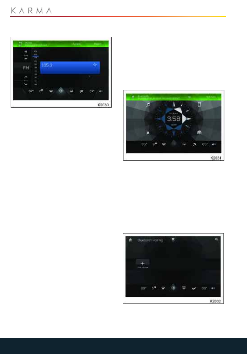
64
TOUCHSCREEN
ANSWERING CALLS
When receiving a call, touch Answer or
Decline on the green mode bar at the top of
the display.
The incoming call mode bar will appear
regardless of which screen the system is
currently displaying.
Calls can also be disconnected with the
mode bar.
To switch to the call-in-progress screen,
touch the phone icon on the left side of the
mode bar.
PAIRING A PHONE
To use the Phone feature, a Bluetooth
enabled phone must be connected to the
vehicle. Follow the steps below to pair a
phone.
Note: To pair an additional phone, access
the Bluetooth Settings menu from the main
phone display, then pick up the procedure
at Step 4.
BLUETOOTH
To pair a phone via Bluetooth:
1. Touch the phone icon on the main
display screen.
2. The first time a phone is paired, a
message will appear at the top of the
screen asking if you would like to pair a
phone;
3. Touch Yes.
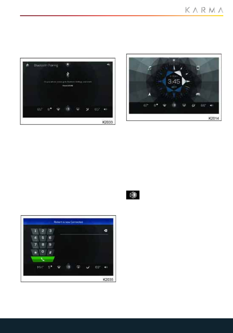
65
TOUCHSCREEN
4. Press "Pair Phone" to begin the pairing
process.
The system will search for available
devices. Ensure Bluetooth is enabled on
your device, and set to discoverable.
5. If there is more than one available
Bluetooth device, select the correct
device from the list. The system will then
begin to pair the phone.
6. Verify that the displayed pairing code
on the Revero screen matches the one
on the phone's display.
7. On the phone, select Revero to allow
the phone to connect.
8. Once the phone has paired, a mode bar
will appear, indicating that the process
is complete.
After a moment, the phone dialer screen
will appear. From here, the user can:.
•Make a call
•Touch the Home button to return to the
main screen
MINIBAR
The bar that runs along the bottom of the
display is called the MiniBar. Touch the
center icon to access the main climate
control screen. Touch the far right icon for
volume control. The three icons to each side
of the center icon are quick-controls for the
climate control system, allowing the user to
adjust the temperature and airflow without
leaving the home screen.
CLIMATE CONTROL
Touch the half snowflake/half sun
icon at the center of the MiniBar to
access the main climate control screen.
This screen contains options for all climate
control settings. From the main screen the
user can control the temperature and
airflow for the following settings:
•Air conditioning (driver and passenger
levels)
•Heating (driver and passenger levels)
•Ventilation (driver and passenger
levels)
•Seat warmers
•Fan speeds
•Defrost
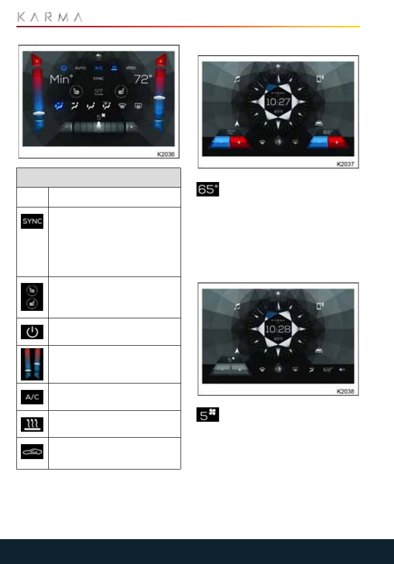
66
TOUCHSCREEN
TEMPERATURE
Touch the temperature setting
value on the MiniBar to access the
pop-up temperature control. Touch the + to
raise the temperature or the - to lower it.
The icon will display the chosen
temperature. With the dual climate control
system, the driver and passenger can input
different temperatures.
FAN SPEED
The fan speed control is indicated by
a number and a small fan
illustration. Touching the icon will generate
a pop-up speed control. Touch the + to
raise the fan speed, or touch - to lower the
fan speed. Fan speed is not an available
dual climate control setting.
Climate control
Icon Description
The dual independent cabin
control icon will be blue when the
driver and passenger
temperature control values are
the same. When the icon is off
(illustrated here), the control
values are independent.
Seat warmer icons control the
heat generated by the seat
warmers. There are 4 settings:
OFF, 1, 2, 3.
This is the climate control ON
and OFF button.
Climate control system
temperature adjustment.
Air Conditioning system cools
the cabin.
Heating system heats the cabin.
Air circulation controls the flow
of air for the cabin. The options
are recirculation or outside air.
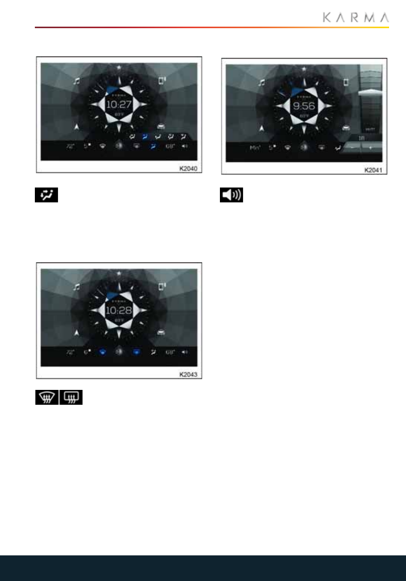
67
TOUCHSCREEN
VENTILATION
Touch the Ventilation icon in the
center of the right side of the
MiniBar to select the desired airflow
configuration. Ventilation is not an
available dual climate control function.
DEFROSTERS
The defroster icons are
located to each side of the
main climate control icon. The left icon
controls the main windshield defroster,
while the right icon controls the rear
window defroster. These icons do not bring
up a pop-up menu, but are simply function
buttons. Touching the defroster icon once
turns it on, then touching it again turns it
off. When the defroster is on, the icon is
blue.
VOLUME CONTROL
Touch the speaker icon at the
bottom right corner of the main
display to bring up the volume controls.
Pressing the desired level will move the
indicator to that level and adjust the
volume accordingly. Touch and hold the
slider and slide it up or down to adjust the
volume in increments. Press the Mute icon
to mute the sound (icon will turn blue);
press the mute icon again to return to the
previous volume. The volume display will
disappear if left untouched for five
seconds.
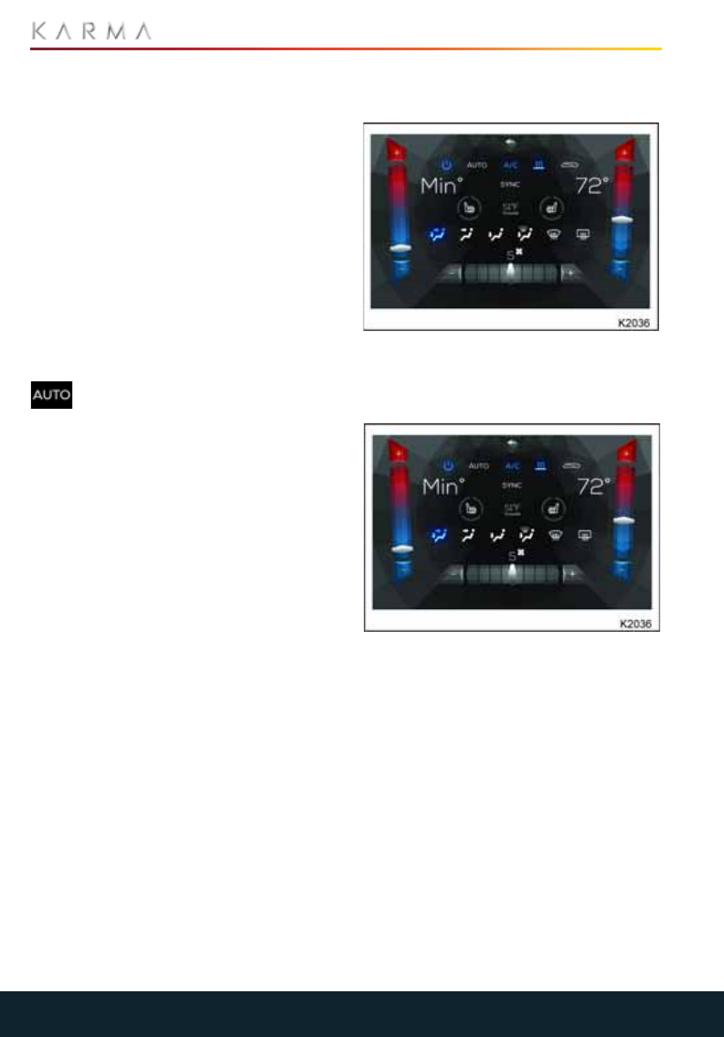
68
CLIMATE CONTROL
Climate Control
USING THE SYSTEM
Note: The blower, heating and air
conditioning systems are powered by the
battery. Prolonged use will decrease the
range of the vehicle in STEALTH.
AUTO CLIMATE CONTROL
The climate control system features
automatic temperature and air distribution
control and is programmed to maintain
optimum levels of comfort within the
vehicle in all but the most severe climatic
conditions.
It is recommended that automatic climate
control is selected as the normal operating
mode.
Touch the icon to switch on
automatic climate control then
adjust the temperature to the desired
temperature.
The system will then automatically adjust
the heating, air conditioning, air
distribution, blower speeds and air
recirculation to maintain the desired
temperature.
The air distribution and blower controls can
be operated independently to override
AUTO mode. If AUTO mode is overridden,
the icon will no longer be highlighted. Press
AUTO again to return to automatic mode.
Note: If the air distribution and blower
controls are used independently, the
system may not be able to maintain the set
temperature.
BLOWER SPEED/TEMPERATURE
CONTROL
Touch a point on the Slider to increase or
decrease the desired blower speed
between 0 and 10.
Touch a point on the Slider to set the
desired interior temperature.
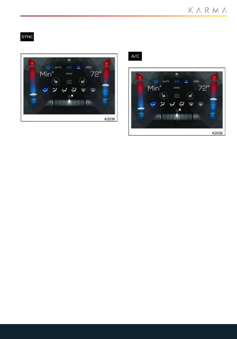
69
CLIMATE CONTROL
DUAL ZONE TEMPERATURE
Touch the icon to switch between
single zone and dual zone
temperature control.
When dual mode is active, the temperature
for the driver and passenger sides of the
interior can be independently adjusted.
Touch a point, up or down on the slidebar to
set the desired interior temperatures.
Small incremental changes are made when
the slidebar + or - are selected.
Larger changes can be made by tapping on
the temperature "slidebar scales."
SYNC CLIMATE CONTROL
When the SYNC feature is selected, the
passenger's temperature setting will
automatically match the driver's.
The SYNC feature is automatically
canceled when the temperature setting is
adjusted on the passenger side, or if the
SYNC icon is selected.
AIR CONDITIONING
Note: Air conditioning can be used on its
own or in conjunction with the heating
system.
Touch the icon for cool and
dehumidified air.
Adjust the temperature control to control
the amount of cooling.
It is recommended that air conditioning is
used throughout a journey, to control
window fogging and odors.
Switching off air conditioning will reduce
cooling performance; the amount of
cooling available will be determined by the
outside air temperature. However, the
reduced load on the high voltage battery
may improve vehicle range.
Note: Using the climate control system for
prolonged periods with the air conditioning
off may cause the windows to fog in certain
climatic conditions.
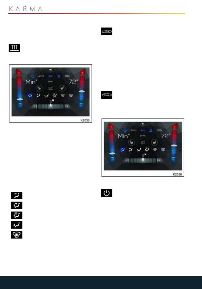
70
CLIMATE CONTROL
HEATING
Note: The heating system can be used on
its own or in conjunction with the air
conditioning system.
Touch the icon to operate the
heating system and warm the air
from the vents.
Adjust the temperature control to control
the amount of heating.
Note: Although the seat heaters consume
energy from the high-voltage battery, they
require less energy than the heating
system and are an alternative way of
keeping warm in the vehicle.
AIR DISTRIBUTION
Touch the respective air distribution icon to
change the location at which air enters the
interior of the vehicle.
Note: Only one air distribution setting can
be selected at a time.
AIR RECIRCULATION
Touch the icon to activate air
recirculation.
Air recirculation prevents air entering from
the outside, and recirculates the air inside
the vehicle.
This prevents the entry of traffic fumes. Air
recirculation also significantly influences
the dehumidifying and cooling
performance of the air-conditioning
system.
FRESH AIR
Touch the icon to switch from
recirculation and to allow fresh air to
be drawn into the vehicle from the outside.
TEMPERATURE DISPLAY OPTION
OFF
Touch the icon to switch off the
heating system, air conditioning and
blower. Any air entering the vehicle
through the vents will be dependent upon
the vehicle speed.
Face level vents
Face and foot level vents
Windshield and foot level vents
Foot level vents
Defrost
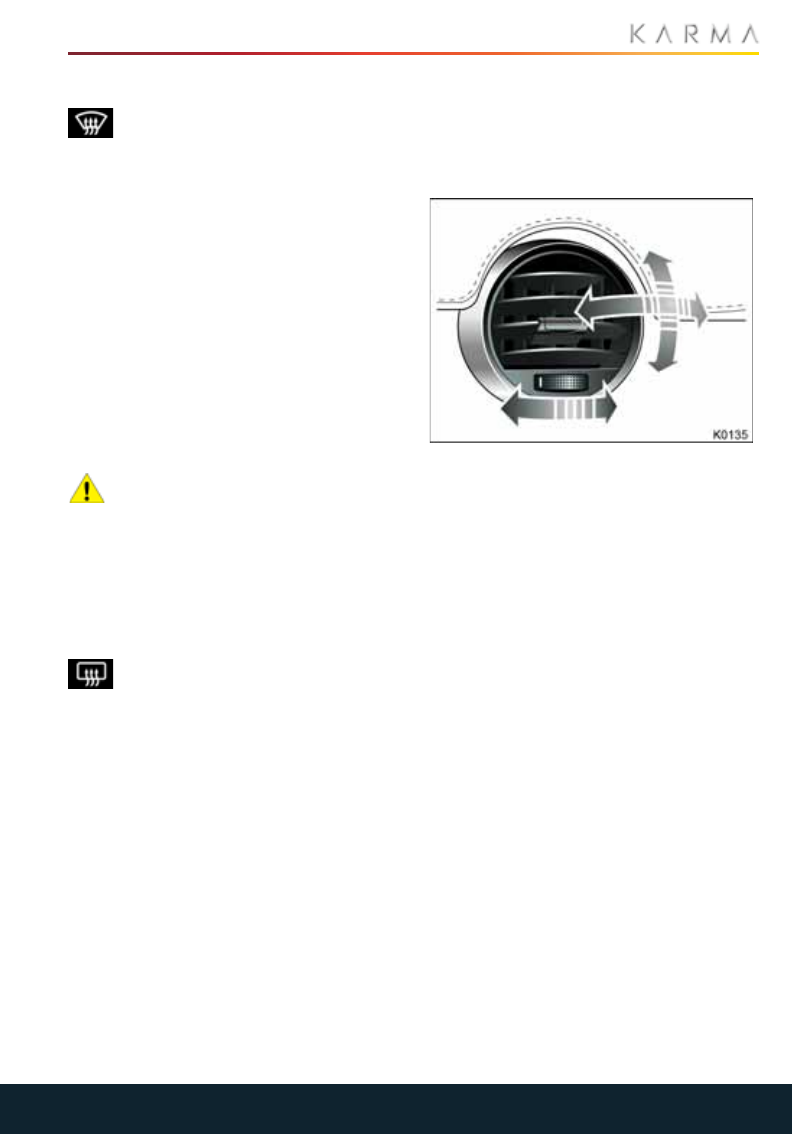
71
CLIMATE CONTROL
WINDSHIELD DEFROSTER
Touch the icon to operate the
windshield defroster. A blue
indicator will be displayed on the icon when
the defroster is operating.
To provide maximum air flow to the
windshield, activating the defroster
automatically adjusts the climate control
settings as follows:
•Air distribution set to windshield vents.
•Air conditioning is switched on.
•Heating is switched on.
•Blower fan is switched on.
Touch the icon again to switch off the
windshield defroster and return the system
to its previous settings.
REAR WINDOW DEFROSTER
CAUTION: To avoid damage to the
heating elements, do not attach
labels to the rear window. Also, do not
scrape or use abrasive materials to clean
the inside of the rear window.
With the vehicle in Drive mode, touch the
icon to operate the rear window heater. A
blue indicator will be displayed on the icon
when the heater is operating.
The rear window heater will operate
for a period of time before
automatically switching off.
VENTILATION
Air is drawn into the vehicle through the
grille in front of the windshield. Keep the
grille clear of obstructions (leaves, snow,
etc.).
Rotate the thumb wheel left or right to
open and close the face level vents. Move
the louvers up, down, or from side to side to
direct the airflow.
The outer face level vents can be directed
onto the side windows to aid in defogging in
cold weather.
Note: When you open the face level vents,
airflow to the foot and windshield vents is
reduced.
CABIN AIR FILTER
Your Revero has a cabin air filter installed
that prevents pollen, industrial fall-out,
road dust and other particles from entering
the vehicle via the vents.
The cabin air filter must be replaced every
20,000 miles (32,000km). Failure to
replace the air filter will result in reduced
air flow into the vehicle.

72
CLIMATE CONTROL
OPERATING NOTES
•Heating is provided by a high voltage
electric heater and cooling is provided
by a high voltage all-electric air
conditioning system. Both of these
systems are located under the hood.
•In addition to cooling the passenger
compartment, the air conditioning
system also cools the high voltage
battery coolant.
•In high ambient temperatures, the air
conditioning system may be activated
even if you have manually switched it
off on the touchscreen. This is normal,
with priority being given to cooling the
high voltage battery to ensure that cell
temperatures stay within a range that
supports long life and efficient
performance.
•For the climate control system to
function efficiently, all windows should
be closed, and the air intake vents free
from ice, snow, leaves or other debris.
•To reduce the time for the vehicle to
reach a comfortable temperature
during hot weather, drive with the
windows slightly open for two to three
minutes after start-up.
•In very humid conditions, slight screen
fogging may be experienced when the
air conditioning system is turned on.
This is a natural occurrence and will
clear after a few seconds.
•Surplus water produced by the
dehumidifying process is drained
beneath the vehicle. This may result in a
small pool of water forming when the
vehicle is stationary and is not a cause
for concern.
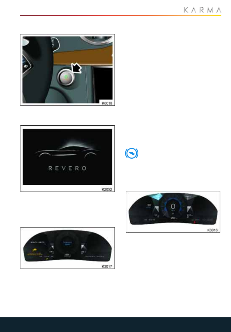
73
STARTING AND DRIVING
Starting and Driving
STARTING THE VEHICLE
The Start/Stop button is used to put the
vehicle into Accessory and Drive modes.
Note: The Start/Stop button will only be
operational if a valid key fob is detected
within the vehicle.
ACCESSORY MODE
In Accessory mode, all the electrical
features and controls, except the heating
and air conditioning system, can be
operated but the vehicle cannot be driven.
To put the vehicle in Accessory mode:
1. Ensure the key fob is inside the vehicle.
2. Make sure the brake pedal is NOT
applied.
3. Press the Start/Stop button.
The vehicle enters Accessory mode and
the indicator lights on the DIS illuminate
briefly.
Note: Display functions are not
available immediately, please allow the
information screens to load and
display. As with any personal computer
or infotainment device several seconds
are required to boot before the device
is fully operational. When using
navigation, always set the driver
information system and touch screen
views before driving.
4. The amber indicator light on the
Start/Stop button will illuminate.
The brake pedal indicator light will
illuminate in the DIS.
Note: If left in Accessory mode, the vehicle
will automatically turn itself off after 10
minutes.
DRIVE MODE
In Drive mode, the vehicle’s high voltage
electrical system is engaged, allowing the
vehicle to be driven.
To put the vehicle in Drive mode:
1. Ensure the key fob is inside the vehicle.
2. Depress the brake pedal.
3. Press the Start/Stop button.
TURNING OFF THE VEHICLE
To turn off the vehicle:
1. Ensure the P (Park) is selected.
74
STARTING AND DRIVING
2. From either the Accessory or Drive
mode, press the Start/Stop button to
turn the vehicle off.
Note: The vehicle cannot be put into
Accessory mode if the vehicle is in motion.
EMERGENCY SHUT DOWN
PROCEDURE
WARNING: The vehicle’s electrical
system powers the power steering
pump, brake servo pump, anti-lock braking
system and electronic stability control
system. Shutting down the electrical
system with the vehicle in motion will
increase braking distances, as well as
requiring greater effort to steer the vehicle,
with a possibility of the wheels locking
causing the vehicle to skid. Only enact this
shutdown procedure in an emergency.
In an emergency situation, if you need to be
able to shut the vehicle down while it is still
in motion, the vehicle electrical system can
be turned off by pressing the Start/Stop
button three times in quick succession or by
pressing and holding until the vehicle
powers off.
KEY FOB NOT DETECTED
If the Start/Stop button is pressed and the
key fob is not detected by the vehicle, a
warning message will be displayed in the
DIS. If you have the key fob and it is still not
detected, use the keyless start backup
procedure.
If the vehicle is in Accessory or Drive
modes and the vehicle can no longer
detect the key fob, an indicator light
will illuminate and the warning message
“KEY FOB LEFT VEHICLE” will be displayed
on the DIS. This will be accompanied by a
rapid chime.
Note: Always make sure you have the key
fob with you before making a journey as
you will be unable to restart the vehicle
once it has been switched off.
KEYLESS START BACKUP PROCEDURE
If the vehicle has been unlocked using the
emergency key blade or the key fob is not
detected by the vehicle, it will be necessary
to use the keyless start backup to disarm
the security system and start the vehicle.
1. Hold the key fob next to the driver
exterior side mirror mounting bracket
with the buttons facing away from the
vehicle
When the key fob is positioned in this area
it will be recognized by the vehicle and a
message will be displayed in the DIS.
Holding the key fob in position and
depressing the brake pedal, press and
release the Start/Stop button to put the
vehicle in Drive mode.
Once the vehicle is in Drive mode, you no
longer need to hold the key fob against the
mirror bracket.
Note: If the key fob is still not recognized, or
the vehicle fails to enter Drive mode,
contact Karma Automotive or your local
Karma Service Provider.
TYPE APPROVAL
FCC Warning Statement:
This device complies with Part 15 of the
FCC Rules. Operation is subject to the
following two conditions:
1. This device may not cause harmful
interference, and
2. This device must accept any
interference received, including
interference that may cause undesired
operation.
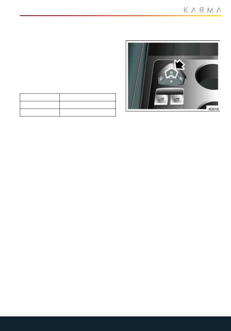
75
STARTING AND DRIVING
This equipment complies with FCC
radiation exposure limits set forth for an
uncontrolled environment. End users must
follow the specific operating instructions
for satisfying RF exposure compliance. This
transmitter must not be co-located or
operating in conjunction with any other
antenna or transmitter.
Changes or modifications not expressly
approved by the party responsible for
compliance could void the user's authority
to operate the equipment.
Under Industry Canada regulations, this
radio transmitter may only operate using
an antenna of a type and maximum (or
lesser) gain approved for the transmitter
by Industry Canada.
To reduce potential radio interference to
other users, the antenna type and its gain
should be so chosen that the equivalent
isotropically radiated power (e.i.r.p.) is not
more than that necessary for successful
communication. This device complies with
Industry Canada license-exempt RSS
standard(s). Operation is subject to the
following two conditions: (1) this device may
not cause interference, and (2) this device
must accept any interference, including
interference that may cause undesired
operation of the device.
SELECTING A PROPULSION
MODE
With the vehicle in Drive mode, press the
required button to select a mode.
Note: If the READY indicator light flashes
when selecting a mode, a fault has been
detected. Try selecting the mode again; if
the fault persists, contact your Karma
Service Provider.
•P (Park)
With Park engaged, the propulsion unit
is locked and the rear wheels cannot
turn.
To select another mode when the
vehicle is in Park, the vehicle must be in
Drive mode and the brake pedal
depressed.
Note: P (Park) is automatically engaged
whenever a charging cable is
connected to the charging port to
prevent the vehicle being accidentally
driven while still connected.
•R (Reverse)
Selectable whenever the vehicle is
stationary or its forward speed is less
than 30 mph (48 km/h).
•N (Neutral)
Allows the vehicle to be stationary
without the propulsion unit being
locked.
To select another mode when the
vehicle is in N (Neutral) and moving at a
speed less than 5 mph (8 km/h), you
must press the brake pedal. At speeds
USA FCC ID: AQO005
Canada IC: 10176A-005
Model No. A-0783G02
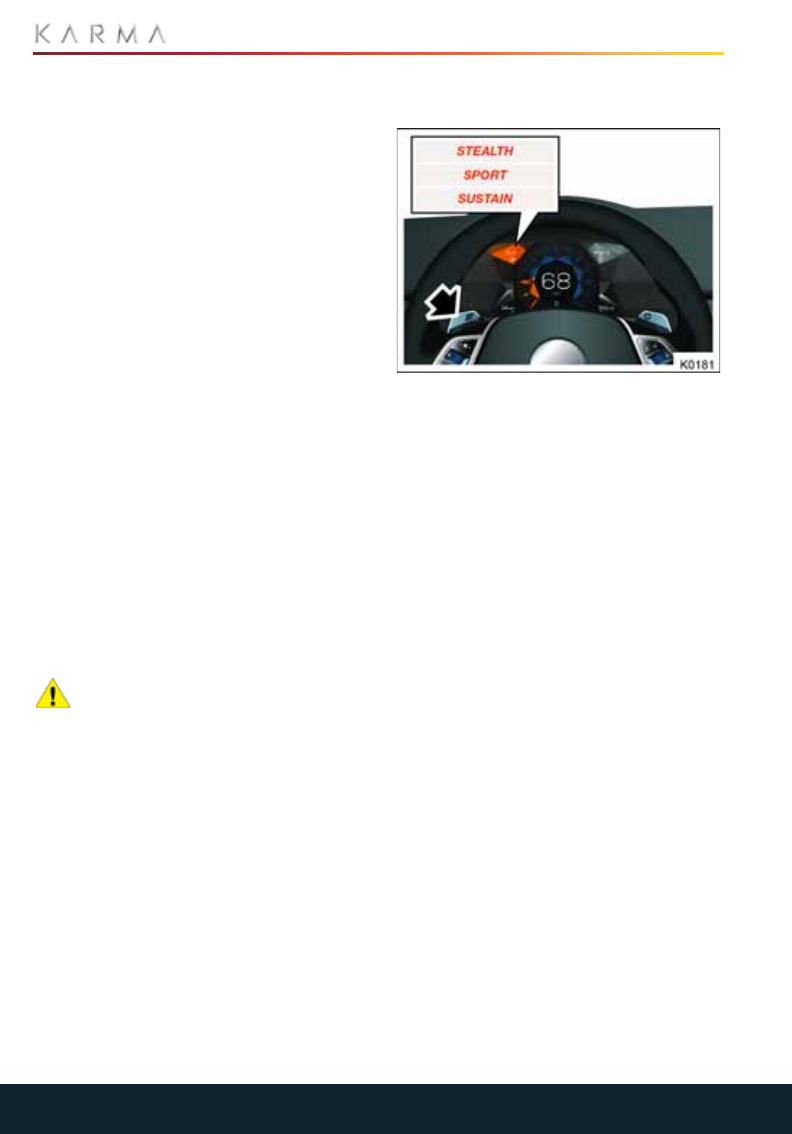
76
STARTING AND DRIVING
above 30 mph (48 km/h) you can only
select the drive mode suitable for the
current direction of travel.
•D (Drive)
Selectable whenever the vehicle is
stationary or its speed is less than
30 mph (48 km/h) in reverse.
The DIS will show the currently selected
mode and the button associated with the
mode will also illuminate.
Note: Similar to a conventional automatic
transmission, when you select D (Drive) or
R (Reverse), the vehicle will move (creep) if
you do not have the parking brake applied
or the brake pedal depressed.
DRIVING MODES
Your Revero has three selectable drive
modes: Stealth mode, Sport mode and
Sustain mode. The currently selected drive
mode is displayed on the DIS.
With the vehicle in Drive mode, the desired
driving mode is selected using the selection
paddles on the steering column.
Note: The vehicle will default to STEALTH
mode if the electric range is greater than 0
miles. If the electric range is 0 miles, the
vehicle will then default to SUSTAIN mode.
CAUTION: Do not drive through water
of an unknown depth. Besides being a
possible safety hazard, driving through
water deeper than 3 inches (7.5 cm) can
cause internal combustion engine damage
due to water ingestion through the air
intake system. If you do not know the depth
of water, do not drive through it. If possible
place the vehicle in Stealth mode, shut the
internal combustion engine off, this can
help in prevent in water ingestion for any
water crossing. If you are forced to enter
standing/flowing water despite using best
efforts to avoid it, drive very slowly (not to
exceed 5 mph (8 kph) and do not stop in the
water. If the internal combustion engine
stalls in the water, do not attempt to
restart it – have the vehicle towed out of
the water and have the vehicle serviced to
prevent any additional engine damage.
STEALTH, SPORT AND SUSTAIN
MODES
In STEALTH driving mode, the vehicle is
powered exclusively from the high voltage
battery. When the charge level of the
battery falls to approximately 15%
(0 mile electric range), the vehicle will
automatically switch to SUSTAIN driving
mode.
In SPORT mode, the vehicle is powered by
both the generator and high voltage
battery. This provides more power to the
traction drive motors and improves vehicle
performance.
In SUSTAIN driving mode, the vehicle will
use gasoline as the energy source, and
sustain the charge level in the high voltage
battery.
To change among STEALTH, SPORT and
SUSTAIN driving modes, briefly pull the
left-hand paddle towards you and release.
Pull and release the paddle again to select
the next available mode.
RESTRICTED PERFORMANCE
In the event when high a amount of wheel
traction power is needed, such as climbing
up a hill at highway speeds, if the vehicle
displays a yellow hazard symbol or text of
"restricted performance", the driver should
enter SUSTAIN or SPORT MODE.
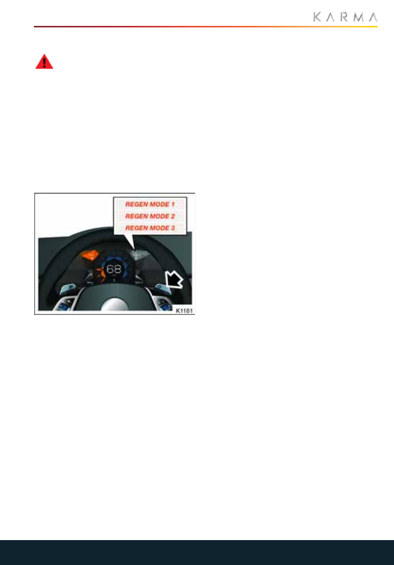
77
STARTING AND DRIVING
REGEN MODE
WARNING: It is recommended that
you do not use SPORT mode on
surfaces covered in snow or ice as this
could adversely affect vehicle handling.
REGEN mode simulates the engine braking
you would experience on a traditional
vehicle when descending a hill, and
increases the amount of energy generated
through regenerative braking when the
brake pedal is not pressed.
REGEN mode has three different levels
which simulate different levels of engine
braking.
To select REGEN mode 1:
The vehicle defaults to REGEN mode 1. The
vehicle will experience little resistance and
the DIS will indicate REGEN 1 in the display.
To select REGEN mode 2:
Briefly pull and release the paddle to select
the next available REGEN mode.
To select REGEN mode 3:
Briefly pull and release the paddle again.
The vehicle will have an increased feeling of
drag while coasting and the DIS will
indicate REGEN 3 in the display.
The REGEN modes circle around from
REGEN 1, REGEN 2 and REGEN 3; pulling
and releasing the REGEN paddle will select
the next available REGEN mode in the
sequence.
Note: Holding the paddle does de-select
the REGEN 2 or REGEN 3 selection and go
back to REGEN 1.
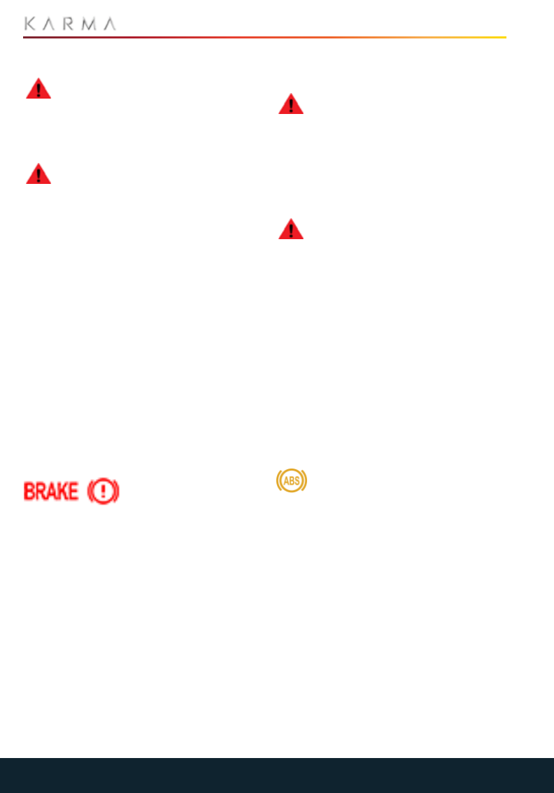
78
BRAKES
Brakes
GENERAL INFORMATION
WARNING: Driving through heavy
rain or water can have an adverse
effect on braking efficiency. Under such
circumstances, It is recommended that you
lightly apply the brakes intermittently, to
keep the brakes dry.
WARNING: Do not rest your foot on
the brake pedal while the vehicle is in
motion unless you are applying the brake
pedal.
Your Revero is equipped with an advanced
electro-hydraulic brake control unit that
combines the vehicle’s conventional
hydraulic brake system with its
regenerative braking system to meet the
requirements for slowing the vehicle.
The brake control module interprets the
braking request and uses regenerative
braking, conventional hydraulic braking or
a combination of both as necessary.
Unlike conventional vehicles which have a
vacuum operated brake servo to assist in
the application of the brakes, A pump
within the control unit pressurizes the
brake fluid to apply the brakes. You may
occasionally hear the pump when the
system is operating. This is normal and not
a cause for concern.
If the brake warning
light illuminates while
driving, accompanied
by the message, ”Service Brakes,” stop the
vehicle as soon as safety permits and a
have the cause investigated by your local
Karma Service Provider.
In the event of a brake problem or a loss of
vehicle power, the brake system can still be
operated to bring the vehicle to a stop, but
the brake pedal may be harder to push and
the stopping distance may be longer.
ANTI-LOCK BRAKING SYSTEM
(ABS)
WARNING: Always maintain an
appropriate stopping distance from
the vehicle in front of you. ABS cannot
overcome the physical limitations of trying
to stop the vehicle in too short a distance,
cornering at too high a speed, or the
danger of hydroplaning, i.e. where a layer
of water prevents adequate contact
between the tires and the road surface.
WARNING: Always drive with
consideration for the current road,
weather and traffic conditions.
The ABS is designed to prevent the wheels
from locking while braking, thereby
enabling steering control to be retained.
Under normal braking ABS will not be
activated. However, if the braking force
exceeds the available adhesion between
tires and road causing the wheels to lock,
then ABS will automatically come into
operation.
The ABS monitoring system checks that all
electrical components are working
correctly as soon as the vehicle is put into
Accessory mode, and also at frequent
intervals during a journey.
The ABS warning light illuminates
briefly as a bulb check when the
vehicle is put into Accessory mode. If
the light illuminates at any other time, the
system has detected a fault and the ABS
system has been shut down.
Note: The other functions of the braking
system remain fully operational and are
not affected by any loss of the ABS.
However, braking distances may increase.
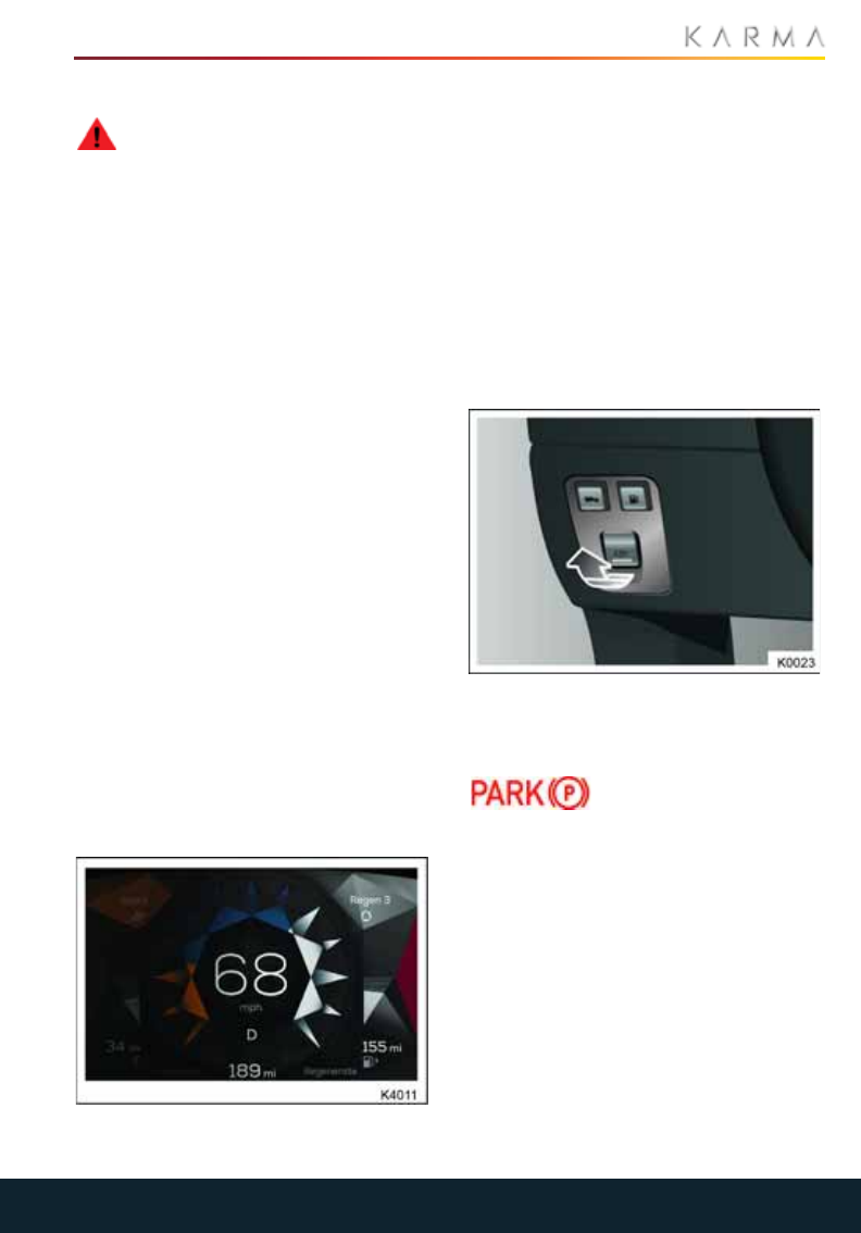
79
BRAKES
EMERGENCY BRAKING
WARNING: Do not pump the brake
pedal; this will interrupt operation of
the ABS and may increase braking
distance.
In an emergency, apply full pedal effort
even when the road surface is slippery.
ABS will monitor the rotational speed of the
wheels and vary braking pressure to each
according to the amount of traction
available, thereby ensuring that the wheels
do not lock and that the vehicle is brought
to a stop in the shortest possible distance.
Steering control will be maintained no
matter how hard you brake.
Note: On soft surfaces (powdery snow,
sand or gravel), the braking distance
required by the ABS may be greater than
for non-ABS braking, even though
improved steering would be experienced.
This is because the action of locked wheels
on soft surfaces is to build up a wedge of
surface material in front which assists the
vehicle to stop.
REGENERATIVE BRAKING
Whenever the vehicle is moving and your
foot is off the accelerator, regenerative
braking slows the vehicle and feeds energy
back to the high voltage battery.
By anticipating your stops and simply
removing your foot from the accelerator to
slow down, you can take advantage of the
energy gained from regenerative braking.
The power meter on the DIS provides real-
time feedback on the level of regenerative
braking, indicating the amount of energy
being generated and fed back to the high
voltage battery.
The amount of regenerative braking can
vary depending on the current state of the
battery. For example, you’ll experience a
reduction in regenerative braking if the
battery is extremely hot or cold or if the
battery is already charged to its maximum
allowable level.
PARKING BRAKE
APPLYING THE PARKING BRAKE
With the vehicle stationary, pull the lever
(arrowed) to apply the parking brake.
The indicator light on the
DIS will illuminate.
Note: If the lever is operated while the
vehicle is traveling, the park brake will be
fully applied. The stop lamps will not
illuminate. This function works even when
the vehicle is shut-off.
RELEASING THE PARKING BRAKE
With your foot on the brake pedal, push the
lever to release the parking brake.
The indicator light on the DIS will turn off.
With your foot on the pedal, pull the switch
to engage the parking brake.
The indicator in the DIS should illuminate
when the parking brake is engaged.

80
BRAKES
ERROR MESSAGES
WARNING: If an error is detected by
the parking brake, never rely on the
parking brake to hold the vehicle on a slope.
If an error is detected by the parking brake
system, both the brake system and parking
brake warning lights on the DIS will flash
and a message will be displayed in the DIS.
When the 12 Volt disconnect procedure is
performed, or the #10 fuse has been
removed from the fuse panel, a text
message will appear in the DIS and the
parking brake icon will be flashing alerting
the driver to re-calibrate the parking brake.
To re-calibrate the electronic parking
brake, perform the following:
1. Place the vehicle in system Ready
mode. Pull the parking brake button,
then push the button.
2. The icon will stop flashing and the text
message will disappear.
EMERGENCY USE
CAUTION: Driving the vehicle with the
parking brake applied, or repeated
use of the parking brake to slow the vehicle,
may cause serious damage to the brake
system.
In an emergency, with the vehicle traveling
more than 2mph (3km/h), pulling and
holding the parking brake lever gives a
gradual reduction in speed.
Note: If the vehicle is moving and the
parking brake is applied, the system will
automatically release the parking brake
after 10 seconds to prevent damage to the
system and the message “PARK BRAKE
CANNOT APPLY” is displayed.
The parking brake must be reapplied to
continue slowing the vehicle.
Message Action
Park brake error. The system has
detected an error.
Refer problem to
your Karma Service
Provider as soon as
possible.
Park brake
cannot apply. The parking brake
cannot be applied.
Refer problem to
your Karma Service
Provider as soon as
possible.
Park Brake
Cannot Release. The parking brake
cannot be released.
Do not drive vehicle!
Refer problem to
your Karma Service
Provider as soon as
possible.
Calibration
Required. Apply
Foot and Park
Brake.
Apply the foot brake
and then apply the
parking brake to
calibrate the system.
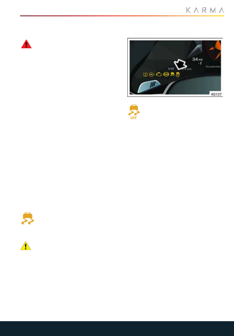
81
ELECTRONIC STABILITY CONTROL
Electronic Stability Control
ELECTRONIC STABILITY
CONTROL (ESC)
WARNING: No electronic system can
remove the need for safe driving
practices. Although the Electronic Stability
Control can help to maintain control of the
vehicle, it cannot prevent any accident
which may result from the vehicle turning
at too high a speed or from
careless/dangerous driving techniques.
Note: By default ESC is switched on every
time you start your Revero.
The Electronic Stability Control (ESC)
system uses various sensors to monitor
driver inputs and vehicle motion. Under
certain driving conditions, the ESC system
helps to perform the following functions:
•Controls brake pressure to reduce
wheel slip on one slipping drive wheel so
power is transferred to a drive wheel on
the same axle that is not slipping.
•Controls brake pressure and traction
motor output to reduce drive wheel slip
based on vehicle speed.
•Controls brake pressure at individual
wheels and traction motor output to
help the driver maintain control of the
vehicle in the following conditions:
•Understeer
•Oversteer
When the ESC system is operating
the indicator light on the DIS will
flash to indicate it is in use.
TURNING OFF ESC
CAUTION: Driving with ESC
deactivated can put additional loads
on the brakes. It is recommended that ESC
is switched on for normal driving
conditions.
In some driving conditions it may prove
helpful to deactivate ESC to improve
mobility. These conditions include:
•Starting on a loose surface, such as
gravel or snow.
•Driving in deep snow, sand or mud.
•Rocking the vehicle out of a hole or deep
rut.
The ESC OFF indicator light will
illuminate on the DIS.
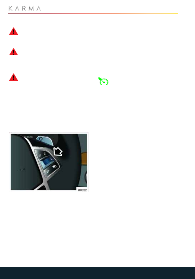
82
CRUISE CONTROL
Cruise Control
CRUISE CONTROL
WARNING: Do not use cruise control
in traffic conditions where a constant
speed cannot easily be maintained or on
winding or slippery road surfaces.
WARNING: It remains the driver’s
responsibility to always ensure that
a safe speed is maintained within the
speed limit, taking account of traffic and
road conditions.
WARNING: Cruise control should not
be used in ice and snow conditions.
Cruise control enables you to maintain a
constant road speed without using the
accelerator pedal. This is particularly useful
for any journey where a constant speed
can be maintained for lengthy periods.
Note: It is important to remember that it is
possible for the vehicle to increase speed
when traveling downhill. This may result in
the vehicle speed exceeding the set speed.
Cruise control is controlled by the switches
on the steering wheel.
ENGAGING CRUISE CONTROL
To engage cruise control, the vehicle’s
speed must be between 20 mph (32 km/h)
and 90 mph (145 km/h).
1. Accelerate until your desired cruising
speed is reached.
2. Press the thumb wheel to the left (SET)
position and release.
3. An indicator light on the DIS illuminates
when cruise control is operating.
If required, vehicle speed can be increased
through normal use of the accelerator.
When the accelerator pedal is released,
road speed will return to the previously set
cruising speed.
Note: The minimum set and resume speed
is 20 mph (32 km/h).
CANCELING CRUISE CONTROL
Cruise control can be canceled by
pressing the switch on the steering
wheel. The indicator light on the DIS
will turn off.
Note: Cruise control is also canceled when
the brake pedal is pressed, REGEN mode is
selected, ESC is turned Off, or if the
vehicle’s speed falls below 20 mph
(32 km/h).
RESUMING CRUISE CONTROL
•To resume cruise control at the
previously set speed, press the thumb
wheel to the right (RES).
Note: Cruise control will only be resumed if
the vehicle’s speed is more than 20 mph
(32 km/h).
CHANGING THE CRUISING SPEED
The vehicle’s set cruising speed can be
adjusted as follows:
•To decrease the set speed, press and
hold the thumb wheel to the left.
To decrease the speed in smaller
increments move the thumb wheel to
the left and release. Each operation of
the thumb wheel will decrease the
speed by 1 mph (2 km/h).
•To increase the set speed, press and
hold the thumb wheel to the right.
To increase the speed in smaller
increments move the thumb wheel to
the right and release. Each operation of
the thumb wheel will increase the speed
by 1 mph (2 km/h).
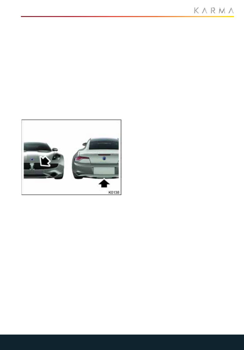
83
EXTERIOR SOUND
Exterior Sound
EXTERIOR SOUND
Unlike a traditional vehicle powered by an
internal combustion engine, electric
vehicles are inherently quiet at low speeds.
Although this potentially provides a large
benefit by reducing the levels of traffic
noise from passing vehicles, sound also
acts as a warning to other road users. It
signifies the presence of a vehicle, its
speed, direction and acceleration.
To help reduce this safety risk, your Revero
has been equipped with an exterior sound
system to alert pedestrians and other road
users to your presence.
Two speakers are located on the exterior of
your Revero, one under the front of the
vehicle and another under the rear.
USING THE SYSTEM
Note: The exterior sound system is
controlled automatically by the vehicle.
There is no need for driver intervention.
When the vehicle is put into Drive mode, the
exterior sound system is switched on. A
pulsing sound will be heard from the
exterior speakers.
As the vehicle’s speed increases, the pitch
of the sound increases until the vehicle’s
speed reaches approximately 30 mph
(50 km/h). At this speed the volume of the
sound will fade out and the exterior sound
is turned off.
The exterior sound will remain off until the
vehicle’s speed is reduced to
approximately 28 mph (45 km/h). At this
speed, the exterior sound is switched on
and the sound will fade in. As the vehicle
slows, the pitch of the sound will decrease.
Note: The exterior sound system remains
active even when the vehicle is in [P] Park.

84
DRIVERS ASSISTANCE
Drivers Assistance
ADVANCED DRIVER
ASSISTANCE SYSTEM (ADAS)
WARNING: Lane Departure Warning
(LDW) and Forward Collision
Warning (FCW) features are for guidance
purposes only and are only designed for
providing audio and visual alerts.
WARNING: These are warning
features only, the vehicle cannot
steer itself or brake on its own; the driver is
solely responsible for safely driving the
vehicle.
WARNING: These features are
camera-dependent and the
accuracies may be impacted by visibility
and many other factors. The driver should
not depend on them at any time. If the
ambient lighting is bright enough that the
driver cannot see, then the camera will not
be able to "see" either.
The Karma Revero is equipped with a front
camera - mounted in the interior, on the
windshield - which is responsible for
detecting and warning the driver of
unintended road lane departures and
forward collisions with surrounding
vehicles. This new system has been named
the Advanced Driver Assistance System
(ADAS).
You can enable/disable these features
through the Touch panel on the
Infotainment Unit.
•My Karma>Settings>Safety>Lane
departure warning.
•My Karma>Settings>Safety>Forward
collision warning.
The features of the ADAS are not
operational under certain conditions. This
can happen in many scenarios, like vehicle
speed below the required speed or poor
visibility due to rain, etc.
LANE DEPARTURE WARNING
(LDW)
Lane Departure Warning is only available
at speeds of 44 to 112 mph (60 to 180
km/h).
The driver will not receive any feedback
from the LDW until a vehicle speed of 44
mph is achieved. The driver will then
receive warnings when attempting to
change lanes.
The system will be automatically
disengaged when wipers are active. This
means LDW is not be available on a rainy
day.
LANE DEPARTURE WARNING
1. Same direction
•For example: When the left turn
signal is selected, and the vehicle
turns left, no warning will be given.
2. Short indicator
•For example: If the turn signal has
been activated, but no lane change is
detected after a period of time, the
system automatically cancels the turn
signal.
•No warning should sound if the
vehicle turns left within 5 seconds
after the indicator has turned off.
3. Wrong indicator
•For example: When the left turn
signal is selected, but the vehicle turns
right, the system will activate an
audible and visual warning.
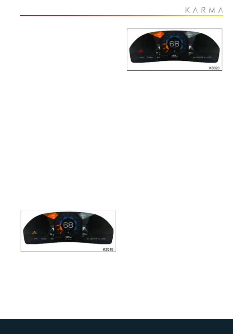
85
DRIVERS ASSISTANCE
4. No indicator
•For example: If the vehicle drifts left
without a turn signal selected, the
system will activate an audible and
visual warning.
LANE DEPARTURE SENSITIVITY
The user can select different sensitivity
through the touch panel.
1. Early
•Audio and visual warnings are
triggered when the wheel is too close
to the lane mark.
2. Normal
•Audio and visual warnings are
triggered when the wheel is touching
the lane mark. This is the default
setting for LDW.
3. Late
•Audio and visual warnings are
triggered when the wheel is driving on
the lane mark.
FORWARD COLLISION
WARNING (FCW)
Forward Collision Warning is only available
at speeds ranging from 12.5 to 50 mph (20
to 80 km/h). Activation of the FCW system
can be done through the CIU.
The yellow FCW icon provides early
warning that action may be required to
avoid a collision. There is no audio sounds
to assist with the alert.
The red FCW icon with a soft audio sound
provides warning that immediate action is
required to avoid a forward collision. The
action required might be applying brakes
or swerving to avoid collision.
In the event the red FCW icon with a hard
audio sound occurs, without immediate
action you will be involved in a forward
collision.
The system will be automatically
disengaged when the wipers are activ.e
That means FCW is not available on a rainy
day.
SENSITIVITY SETTINGS
There are 3 level of FCW sensitivities. The
major difference between them is the
"risky" level threshold
1. Early
2. Normal
3. Late
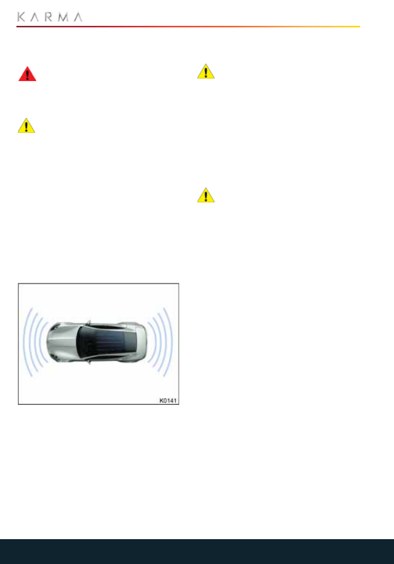
86
PARKING AIDS
Parking Aids
PARK DISTANCE CONTROL
(PDC)
WARNING: The PDC system may not
detect moving objects such as
children and animals, until they are
dangerously close. Always maneuver with
caution and always use your mirrors.
CAUTION: The PDC system is for
guidance only and is not intended to
replace the driver’s visual checks for
obstructions when maneuvering. The
sensors may not be able to detect certain
types of obstructions (for example, narrow
posts, small objects close to the ground and
some objects with dark, non-reflective
surfaces).
The PDC system alerts the driver to any
obstructions that need to be avoided while
maneuvering at low speeds.
The PDC is active only if the gear position in
on Drive or Reverse. When in the Neutral
position, the activation of the front/ rear
sensors depends on the previous state.
The vehicle is equipped with eight
ultrasonic sensors, four on the front
bumper and four on the rear bumper.
The range of the front sensors, as well as
the rear corner sensors, is approximately
3 feet (90 cm), while the two rear center
sensors have a range of approximately
5 feet (1.5 m).
You are made aware of any obstruction,
within range, by an intermittent tone. As
the vehicle moves closer to the obstruction,
the frequency of the intermittent tone
increases.
CAUTION: Systems which use the
same frequency band as the parking
sensors may cause irregular tones to be
emitted.
When the distance between the sensors
and the obstruction is less than about 1 foot
(30 cm) the tone becomes continuous.
Note: PDC is automatically switched off
when the vehicle’s forward speed exceeds
7.5 mph (12 km/h).
CLEANING THE SENSORS
CAUTION: When washing the vehicle,
avoid aiming high pressure water jets
directly at the sensors. Do not use abrasive
materials or hard/sharp objects to clean
the sensors.
If the sensors are obscured by dirt, ice or
snow their performance may be impaired.
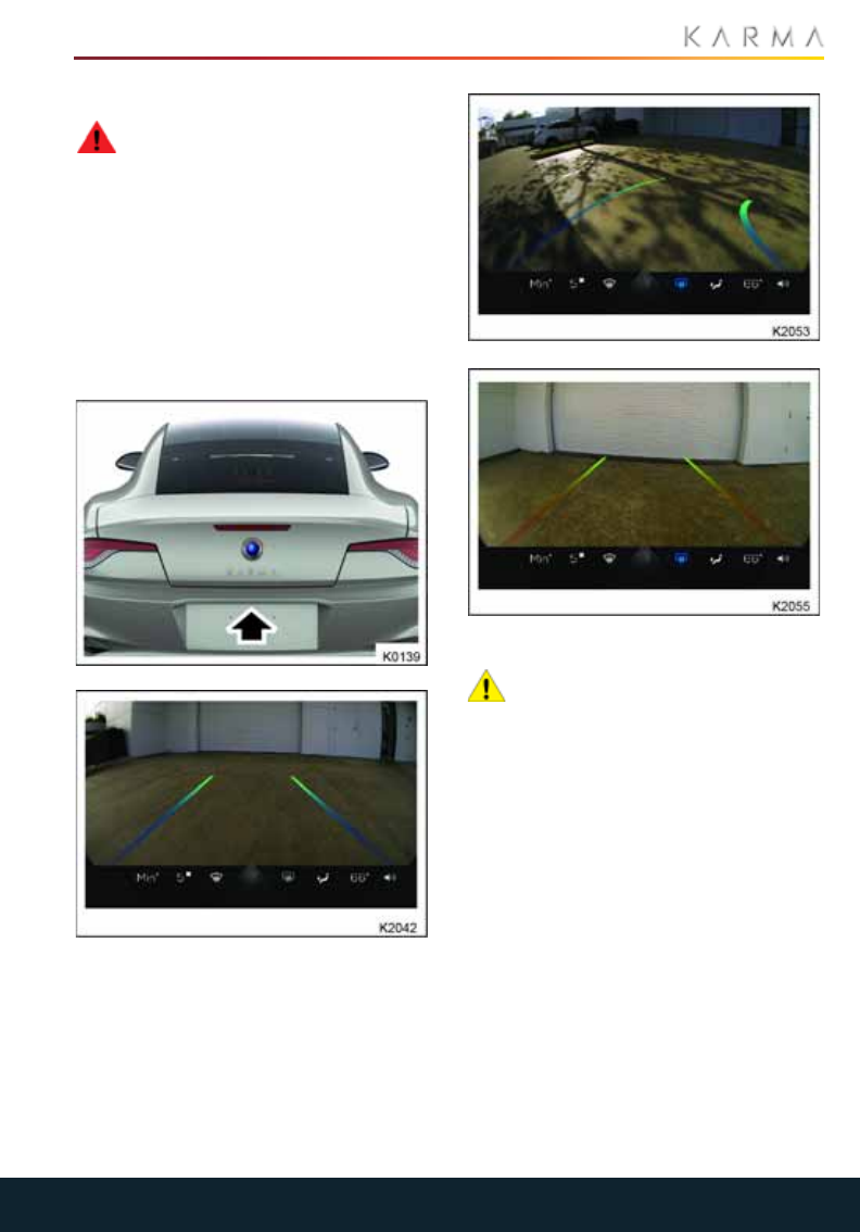
87
PARKING AIDS
REAR VIEW CAMERA
WARNING: It remains the driver's
responsibility to detect obstacles
and estimate the vehicle's distance from
them when reversing. Some overhanging
objects or barriers, which could possibly
cause damage to the vehicle, may not be
visible by the camera.
The rear view camera is located above the
rear license plate.
When R (Reverse) is selected, the
touchscreen will automatically display the
view from the camera.
CLEANING THE CAMERA
CAUTION: Do not use chemical based
cleaners or harsh abrasives. These
can scratch the surface and permanently
damage the camera lens.
For the best picture, always keep the rear
view camera clean, and do not cover the
camera lens.
To clean the camera lens, use a soft cloth
moistened with water and car shampoo to
remove any build up of dirt on the surface.
Use a soft dry cloth to dry the surface and
polish the lens.
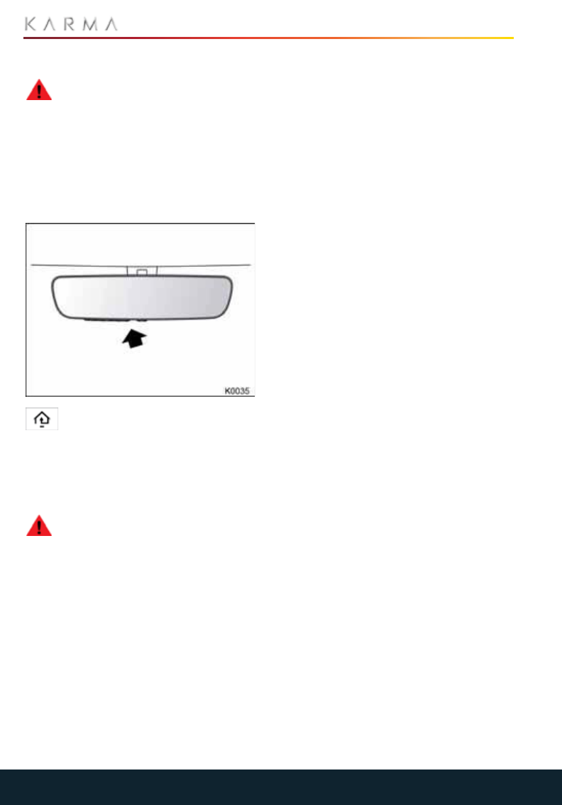
88
GARAGE DOOR OPENER
Garage Door Opener
HOMELINK® TRANSMITTER
WARNING: Do not use this
HomeLink® transmitter with any
garage door that lacks safety stop and
reverse features. A garage door opener
which cannot detect an object in the path
of a closing door and then automatically
stop and reverse the door does not meet
current safety standards. Using a garage
door opener without these features
increases the risk of serious injury or death.
The HomeLink® universal
transmitter is built into the rear
view mirror and provides a convenient way
to replace up to three hand-held
transmitters with a single built-in device.
PROGRAMMING A DEVICE
WARNING: When programming
your HomeLink® transmitter, you will
be operating the garage door or gate. Be
sure that people and objects are out of the
way, to prevent potential harm or damage.
1. Make sure the vehicle is in Accessory
mode.
2. If you have previously programmed
your HomeLink® transmitter, proceed
to step 3. Press and hold the two outer
buttons for approximately 20 seconds.
When the indicator light (arrowed)
begins to flash, release the buttons. Do
not hold the buttons for longer than 30
seconds.
This initializes the HomeLink®
transmitter and erases previous
settings from all three channels.
Note: Do not perform this step when
programming additional hand-held
transmitters.
3. Decide which one of the three channels
you want to program.
4. Position the end of your hand-held
transmitter 1-3 inches (25 - 75 mm)
away from the buttons.
5. Simultaneously press and hold both the
mirror button you want to program and
hand-held transmitter button. The
indicator light will flash slowly and then
rapidly after the mirror successfully
receives the frequency signal from the
hand-held transmitter.
Release both buttons.
6. Press and hold the programmed
garage door opener button and
observe the indicator lamp.
•If the indicator is continuous,
programming is complete and your
device should activate when the
garage door opener button is pressed
and held for approximately 1 to 2
seconds and then released.
•If the indicator lamp blinks rapidly for
two seconds and then glows steadily,
proceed with the following
instructions for Programming rolling
code device equipment.

89
GARAGE DOOR OPENER
PROGRAMMING ROLLING CODE
DEVICE EQUIPMENT
Note: The assistance of a second person
may make the following steps quicker and
easier. Once the button has been pressed
there are only 30 seconds in which to
complete Step 3.
1. At the garage door opener receiver
(motor head unit) in the garage, locate
the learn or smart button/switch.
The name of the button or switch may
vary between manufacturers.
2. Press and release the learn or smart
button.
3. Return to the vehicle and firmly press
and hold the programmed garage door
opener button for two seconds and
release.
4. Repeat the press, hold, release
sequence three times to complete the
programming process.
5. The garage door opener in the rear-
view mirror should now activate the
rolling code device.
REPROGRAMMING A SINGLE BUTTON
To program a device to a previously trained
button:
1. Press and hold the desired pre-
programmed garage door opener
button for at least 20 seconds, but no
longer than 30 seconds, until the
indicator light begins to flash.
2. Without releasing the rear-view mirror
button, position the hand-held
transmitter approximately 1-3 inches
(25 - 75 mm) away from the transceiver
in the rear-view mirror, keeping the
indicator light in view.
3. Carry out Step 3 of Programming a
Device. See “Programming a Device” on
page 88.
ENTRY GATE/CANADIAN
PROGRAMMING
The technology of some entry gates
requires you to press and re-press (cycle)
the hand-held transmitter button every
two seconds during programming.
Continue to press and hold the desired
rear-view mirror button while you cycle
your hand-held transmitter until the
indicator light flashes rapidly.
INFORMATION AND
ASSISTANCE
CAUTION: For security purposes, it is
recommended that all programmed
transceiver buttons are erased before the
vehicle is sold or disposed of.
For information on the range of available
compatible products or accessories, or for
assistance, you should contact your Dealer.
If you would like additional information on
the Homelink Universal Transceiver,
compatible products or to purchase other
accessories, contact your Dealer or you can
also contact the Homelink helpline at
1-800-355-3515 or www.homelink.com.
Note: Keep the original transmitter for
future use or programming procedures if,
for example, you purchase a new vehicle.
Note: The manufacturer is not responsible
for any radio or TV interference caused by
unauthorized modifications to this
equipment. Such modifications could void
the user’s authority to operate the
equipment
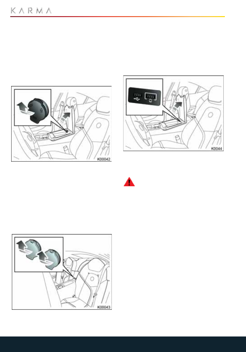
90
ACCESSORY SOCKETS
Accessory Sockets
ACCESSORY POWER OUTLETS
The power socket is suitable for 12V
accessories requiring up to 10A or a
maximum of 125 watts.
Note: The accessory power sockets
operate when the vehicle is in Accessory or
Drive mode.
FRONT 12V POWER OUTLET
The front power outlet is located in the
center console storage compartment and
is always powered.
Note: Extended use of this outlet while the
vehicle is off may drain the 12V battery.
REAR ACCESSORY POWER OUTLETS
Note: The rear accessory power outlets
only operate when the vehicle is in
Accessory or Drive mode.
A USB and a 12V power socket are located
between the rear seats.
Note: The 12V power outlet and the USB
charging port (5V) have hinged covers to
protect them when not in use.
The rear USB port is for charging purposes
only and cannot be used to play music.
USB CONNECTIONS
The center console has two USB ports.
Both USB ports can be used for charging
and playing music.
WARNING: Never read text
messages or enter text on your cell
phone while driving, even if you are
temporarily stopped. Wait until you are in a
safe location away from traffic, put the
vehicle in Park, and then read and type text
on your cell phone.

91
POWER
Power
CHARGING THE VEHICLE
Charging System Components........................................................................................................92
General Information............................................................................................................................92
Charging Port.........................................................................................................................................92
Using the Convenience Charging Cord.........................................................................................93
Charging the Vehicle............................................................................................................................94
EV Charge Station................................................................................................................................96
Charging Time........................................................................................................................................96
Cold Weather Charging Considerations......................................................................................96
FUEL FILLING
Safety Precautions...............................................................................................................................98
Fuel Filler..................................................................................................................................................98
Running Out of Fuel.............................................................................................................................99
Fuel Specification .................................................................................................................................99
Alternative Fuels...................................................................................................................................99
Fuel Tank Capacity...............................................................................................................................99
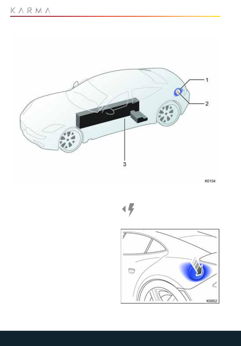
92
CHARGING THE VEHICLE
Charging the Vehicle
CHARGING SYSTEM COMPONENTS
1. Charge port
2. Charge coupler
3. HIgh voltage battery
GENERAL INFORMATION
Your Revero uses an electric propulsion
system to drive the vehicle at all times. To
extend the operating range of the vehicle,
and depending on driving mode, an
internal combustion engine will drive a
generator to produce electricity as
required.
The high voltage battery is the primary
source of electrical energy and a generator
powered by a gasoline engine is the
secondary source.
Your Revero has three operating modes:
STEALTH, SPORT and SUSTAIN. See
“Driving Modes” on page 76.
CHARGING PORT
The charging port is located on the
left-hand side of the vehicle. An
arrow on the battery gauge points to
that side of the vehicle.

93
CHARGING THE VEHICLE
To open the charging port cover, press the
rear edge of the cover and release. The
cover will unlatch and gently spring open.
To close the charging port cover, press
firmly in the center until the cover latches in
place.
USING THE CONVENIENCE
CHARGING CORD
WARNING: Using the charging cord
with a worn or damaged wall outlet
may cause burns or start a fire. Periodically
check the wall plug and charging cord while
the vehicle is charging. If the plug feels hot,
unplug the charging cord and have the
outlet replaced by a qualified electrician.
ELECTRICAL OUTLETS
Ideally, the AC out let should be grounded
with a charging voltage of 240V AC and on
a dedicated circuit rated at 16A (at 3kW) or
32A (at 6kW). That means there should be
no other major appliances connected to
the same circuit.
Wall outlet types:
NEMA 5-15: Regular home use
plug, three prong.
NEMA 14-50: Max charge is 32
amps, traditionally called RV
plugs.
NEMA L6-30: Industrial grade
wall connector with a twist lock.
This is the plug that comes with the
car.
Note: The 14-50 and 5-15 will come in a kit
as additional infrastructure plugs.
Note: The plug has an internal temperature
sensor that may change the charge rate
automatically as the temperature or
battery SOC increases. (The amperage
may change).
If a non dedicated circuit is used, the
current rating of the wall outlet circuit
breaker could be exceeded and cause it to
trip or open.
If you are having issues using the charging
cord at a particular wall outlet, try the
following:
•Use another wall outlet if available.
•Remove other loads on the same circuit.
•Charge the vehicle in reduced level
mode using the charge rate switch on
the travel charger.
EXTENSION CORDS
WARNING: Use of an extension cord
may increase the risk of electric
shock or other hazards.
The use of extension cords should only be
used if charging with 120V AC. All outlets
and charging accessories should be
Residual Current because of limited access
to a power outlet; please observe the
following guidelines:
•The wall outlet should be RCD
protected with a resettable circuit
breaker at the outlet.
•The extension cord should be RCD
protected with a resettable circuit
breaker at the terminating end of the
connector.
•The extension cord should be 12 or 14
gage, and must be a 3 pin conductor.
•The extension cord should be rated for
outdoor usage.
Note: The travel charger automatically
detects the amount of current it can draw
from the wall outlet. Using an extension
cord with a long cord or smaller gage
conductors may prevent the vehicle from
charging.
WARNING: Improper use of portable
electric vehicle charge cords may
cause a fire, electrical shock, or burns, and
may result in damage to property, serious
injury, or death.
WARNING: Do not use extension
cords, multi-outlet power strips,
splitters, grounding adapters, surge
protectors, or similar devices.

94
CHARGING THE VEHICLE
WARNING: Do not use an electrical
outlet that is worn or damaged, or
will not hold the plug firmly in place.
WARNING: Do not use an electrical
outlet that is not properly grounded.
WARNING: Do not use an electrical
outlet that is on a circuit with other
electrical loads.
CHARGING THE VEHICLE
WARNING: Improper use of portable
electric vehicle charge cords may
cause a fire, electrical shock, or burns, and
may result in damage to property, serious
injury, or death.
WARNING: Do not use extension
cords, multi-outlet power strips,
splitters, grounding adapters, surge
protectors, or similar devices.
WARNING: Do not use an electrical
outlet that is worn or damaged, or
will not hold the plug firmly in place.
WARNING: Do not use an electrical
outlet that is not properly grounded.
WARNING: Do not use an electrical
outlet that is on a circuit with other
electrical loads.
CAUTION: The connector end of the
charging cord is heavy and may
damage the vehicle’s paint if dropped
when connecting or disconnecting.
Note: The vehicle should be plugged into a
charger when the ambient temperature is
at or below 32°F (0°C).
Note: When using an EV charging station
that offers a delayed charging feature,
actual charging may not begin for up to 1
hour after the unit is programmed to begin.
The high voltage battery can be charged
either from the internal combustion engine,
or through the electrical grid. When
charging from the electrical grid, there are
three levels:
Level 1: Refers to 120 volts AC charging
through a standard household wall outlet.
Level 2: Refers to 240 volt AC charging
through a professionally installed home
charging station or a commercial charging
station.
DC fast charging: Refers to 480 volt AC
input that is converted to directly charge
the high voltage battery with DC.
Level 1 charging is the most common and
most vehicles come with a travel charger.
This travel charger eliminates the need for
a charging station to be installed at the
vehicle owner’s home. One end of a Level 1
charger is a standard three-prong
household plug. The other end is a
standard J1772 high voltage vehicle
charge connector and provides 2 to 5 miles
of range per hour of charge.
Level 2 charging utilizes a standard high
voltage vehicle charge connector and is
more commonly found in residential
charging, commercial charging, public
parking and places of employment. Level 2
chargers provide 10 to 20 miles of range
per hour of charge. Level 2 can charge at
3.3 kW of 6.6 kW. This depends on wall
outlet capabilities.
DC fast charging utilizes a J1772 Combo
connector. DC fast charging provides an
approximate range of 40 miles in 30
minutes or less.
Note: To optimize the performance of the
High Voltage Battery, Karma Automotive
recommends that the vehicle is charged to
full capacity using the Level 1 travel
charger (120 volt AC charging) at least
once a week. This will help monitor and
actively control battery cell balancing.
Note: Allow the high voltage battery to fully
discharge before recharging. This will
exercise the battery and help maintain
battery health.
1. Position the vehicle so that the charging
cord can easily reach the charging port
on the vehicle.
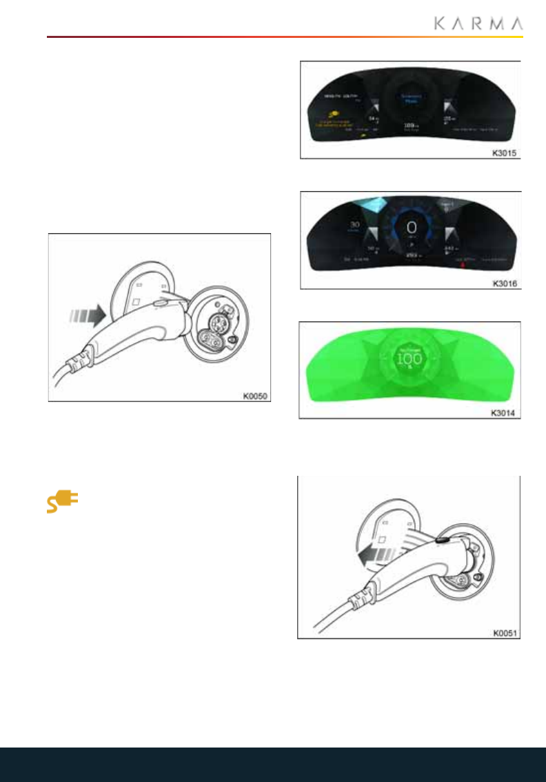
95
CHARGING THE VEHICLE
2. Select Park [P] from the drive selection
button, then press the Start/Stop
button to take the vehicle out of Drive
mode.
The READY indicator on the DIS will
turn off and the doors will unlock to
indicate the vehicle is ready for
charging.
Note: If the cord is connected, the
vehicle will automatically switch to Park
[P].
3. Open the charging port cover.
4. Locate a wall outlet (Standard US 120V,
16A).
5. Insert charger plug into wall outlet.
6. Insert charge coupler into the charge
port.
7.While the vehicle is charging, the
charging indicator light on the DIS
will illuminate and the battery
charge level indicator will begin to
rise.
Note: During charging or in high
ambient temperatures, the cooling fans
and coolant pumps may automatically
switch on for a period of time to cool the
cells in the battery. The fans and pumps
may be audible when in operation. This
is normal and not a cause for concern.
Accessory mode
Drive mode
8. When the vehicle is fully charged, the
DIS will be solid green with a percent of
charge displayed.
9. Press the button on the charging
connector to release the locking clip,
then remove the connector from the
charging port.

96
CHARGING THE VEHICLE
Note: If you try to put the vehicle into
Drive mode with the charging cord
attached, the charging indicator on the
DIS will flash to remind you to
disconnect the charging cord.
10. Close the charge port cover.
WARNING: If the cable is severed,
frayed, or damaged, contact your
local Karma Service Provider.
WARNING: Use the appropriate plug
for the outlet. All of the ground pins
should be in normal operating condition.
EMERGENCY RELEASE CABLE
In the event the charge connector latch
fails to release, use the emergency manual
release cable.
Be sure to end the charging session if the
charger is still connected to a charging
source.
1. Gain entry to the trunk cargo area.
2. Pull the black connector on the left side
of the cargo panel.
3. The charge connector will be manually
unlocked.
After the latch has been released, you will
have to push the cable back into the socket
and push the black ending cap until it locks
in the original resting place.
EV CHARGE STATION
DC FAST CHARGING
A DC charging cable is available at most
charging stations and provides a higher
current connection. This significantly
decreases charging time compared to
charging from a household AC wall outlet.
Note: The charging cable will be locked if
the vehicle is locked during DC Fast
Charging.
Note: For further details on the Electric
Vehicle Charge Station, please contact
your Karma Retailer.
CHARGING TIME
The amount of time it takes to fully charge
the vehicle is dependent upon the
remaining battery charge level and the
available electrical supply (amperage and
voltage).
DC Fast charging will be able to charge the
high voltage battery in 25 minutes, but will
automatically stop charging at 90% State
of Charge (SOC).
As a guide, the following are an
approximate time to charge the high
voltage battery from fully depleted.
Note: Charge time is also impacted by both
the ambient air temperature and the
temperature of the vehicle’s high voltage
battery. If the temperature is outside the
optimal range, the vehicle’s heating and
cooling system will operate to warm or cool
the high voltage battery accordingly. This
will consume some of the energy used for
charging.
COLD WEATHER CHARGING
CONSIDERATIONS
CAUTION: Do not allow the vehicle to
remain in temperature extremes for
long periods without being driven or
plugged in.
If the vehicle will be dormant during periods
of low temperature (32 °F/ 0 °C), it is
recommended that the vehicle be plugged
in and charging.
During an AC charge session, the charging
system may operate fans and pumps that
Charge
type
Power Estimated
time
AC Level 1 120V @ 16A
(15-100%)
10 hours
AC Level II 240V @ 32A
(15-100%)
3 hours
DC Quick
Charge
480V @ 110A
(15-90%)
25 minutes

97
CHARGING THE VEHICLE
result in sounds from the vehicle while it is
turned off.
The charging system may also run the
HVAC, pumps, and fans to manage the
thermal conditions of the high voltage
battery during a DC Fast charge session.
Note: In cold weather conditions, ice may
form around the charge port door. The
charge port door may not open on the first
attempt. Remove ice from the area and
attempt to open the charge port door.
Note: Keep the vehicle plugged in, even
when fully charged, in order to keep the
battery temperature prepared for the next
drive. This is important when outside
temperatures are extremely cold.
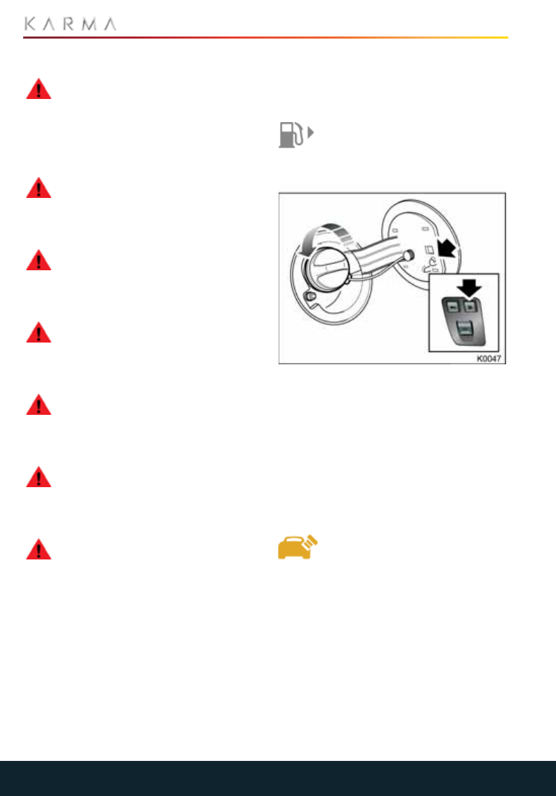
98
FUEL FILLING
Fuel Filling
SAFETY PRECAUTIONS
WARNING: Gasoline vapors are
highly flammable, have a low flash
point and are explosive, especially in
confined spaces. Avoid exposing the vapor
to any potential sources of ignition as the
resulting fire and explosion may cause
serious injuries and/or death.
WARNING: Never fill the vehicle’s
fuel tank while the vehicle is charging
or connected to a charging station. An
accidental spark could cause an explosion
or fire resulting in serious injury or death.
WARNING: Switch off the engine
when refueling, as it is both a source
of extreme temperatures and electrical
sparks. Failure to do so may cause a fire or
explosion.
WARNING: During refueling, switch
off any personal electronic devices
such as mobile phones, or music players.
They have the potential to trigger an
explosion or a fire.
WARNING: Do not smoke, use an
open flame or cause sparks while
refueling. The resulting fire and/or
explosion may cause serious injury or
death.
WARNING: Only use containers
specifically designed for carrying
fuel and always remove them from the
vehicle to fill them. Failure to do so may
result in spillage and cause a fire.
WARNING: Do not overfill the fuel
tank. Overfilling may cause spillage
when the vehicle is driven. Spillage may
also occur if the fuel expands in high
ambient temperatures.
After refueling the vehicle, regardless of
drive mode selected, the engine will be
forced to carry out maintenance on the
Evaporative Emissions System. The engine
must run near idle for approximately five
minutes. The duration of the required
engine run time will be based on the
environmental conditions and the amount
of fuel added. The hotter the weather, and
the more fuel added to the tank, the longer
the Evaporative Emissions System
maintenance will take.
FUEL FILLER
The fuel filler is located on the right-
hand side of the vehicle. An arrow
on the fuel gauge points to that side
of the vehicle.
When your Revero is stationary and
unlocked, press the fuel filler cover release
button located on the driver’s side
dashboard closing panel.
The fuel filler cover will gently spring open.
Twist the fuel filler cap counter clockwise to
release.
A strap secures the fuel filler cap to the
vehicle to prevent loss. A holder is provided
on the door to store the cap while refueling.
When replacing the fuel filler cap,
tighten it until it clicks three times.
Failure to do so may cause the
indicator icon on the DIS to illuminate due
to increased evaporative emission levels.
99
FUEL FILLING
RUNNING OUT OF FUEL
CAUTION: Avoid running out of fuel.
Doing so can cause damage to the
vehicle’s engine, fuel pump and emission
control systems.
When the remaining fuel
reaches approximately 10%
of the maximum fuel level,
the fuel gauge display will turn yellow. If the
fuel level falls to approximately 3%, the low
fuel warning icon will turn red.
FUEL SPECIFICATION
CAUTION: Do not use leaded fuels,
lead substitutes or fuel additives.
Doing so can cause damage to the engine,
fuel and emission control systems.
CAUTION: Only use high quality fuel
as using a lower quality can cause
damage to the engine, fuel and emission
control systems.
CAUTION: Fuel system cleaning
agents should not be used as they
may be harmful to fuel system
components on your Revero.
CAUTION: If the fuel tank is filled with
the wrong type of fuel, do not start
the engine. It is essential that you seek
qualified assistance. Running the engine
can cause serious engine and fuel system
damage.
The correct fuel specification for your
Revero is shown on the inside of the fuel
filler cover.
Only use Premium Unleaded fuel.
Unleaded fuel is essential for proper
operation of the emission control system.
Even a very small quantity of leaded fuel
will damage your vehicle's emission control
system and could invalidate the emissions
warranty.
ALTERNATIVE FUELS
ETHANOL FUELS
CAUTION: Do not use E85 fuels (85%
Ethanol content). If E85 fuels are
used serious engine and fuel system
damage will occur.
Fuels containing up to 10% ethanol may be
used. Ensure the fuel has an octane rating
no lower than that recommended on the
inside fuel filler cover.
METHANOL FUELS
CAUTION: Do not use fuels that
contain methanol. The use of fuels
containing Methanol will seriously damage
fuel system components. Damage caused
by using this type of fuel will not be covered
under the vehicle warranty.
REFORMULATED GASOLINE
CAUTION: Karma Automotive does
not recommend the use of
reformulated gasolines that contain the
additive MMT (Methylcyclopentadienyl
Manganese Tricarbonyl). Fuels containing
MMT can reduce spark plug life and the
performance of the emission control
system.
FUEL TANK CAPACITY
Avoid the risk of running out of fuel and
never intentionally drive the vehicle when
the fuel gauge indicates that the tank is
empty.
Total tank
capacity
10 U.S. gallons
(38 liters)
This Page Intentionally Left Blank

101
MAINTENANCE
Maintenance
MAINTENANCE REQUIREMENTS
General Information..........................................................................................................................103
Scheduled Maintenance ..................................................................................................................103
Owner Maintenance..........................................................................................................................103
Safety......................................................................................................................................................104
Fuel and Emission Systems Components..................................................................................104
HOOD
Opening and Closing the Hood......................................................................................................105
ENGINE COMPARTMENT
Engine Compartment Overview...................................................................................................106
Engine Oil................................................................................................................................................107
Brake Fluid.............................................................................................................................................108
Power Steering Fluid.........................................................................................................................109
Coolant....................................................................................................................................................110
Washer Fluid...........................................................................................................................................111
Approved Fluids and Capacities....................................................................................................112
WIPERS AND WASHERS
Checking the Wiper Blades..............................................................................................................113
Replacing the Wiper Blades............................................................................................................113
Washers..................................................................................................................................................113
CLEANING AND VEHICLE CARE
Cleaning the Exterior..........................................................................................................................114
Cleaning the Solar Roof....................................................................................................................115
Underhood Cleaning..........................................................................................................................115
Polishing the Body...............................................................................................................................115
Paint Damage and Repair................................................................................................................115
Using a Car Cover................................................................................................................................115
Cleaning the Interior...........................................................................................................................115
Floor Mats................................................................................................................................................117
Vehicle Storage.....................................................................................................................................117
FUSES
Replacing a Fuse.................................................................................................................................120
Engine Compartment Fuse Box....................................................................................................120
Fuse Specifications.............................................................................................................................121

102
MAINTENANCE
RAISING THE VEHICLE
Jacking and Lifting the Vehicle .....................................................................................................123
VEHICLE RECOVERY
Transporting the Vehicle ..................................................................................................................124
Attaching the Vehicle Recovery Eye............................................................................................124
Securing the Wheels..........................................................................................................................125
SERVICE INTERVAL SCHEDULES
Service Interval Schedules..............................................................................................................126
Additional Procedures Required at Specific Intervals...........................................................127
Service Types and Required Procedures....................................................................................127

103
MAINTENANCE REQUIREMENTS
Maintenance Requ ireme nts
GENERAL INFORMATION
The safety, reliability and performance of
your car will depend partly on how well it is
maintained. Maintenance is the owner's
responsibility and you must ensure that the
appropriate maintenance is performed
when required and according to the
recommendations specified by Karma
Service Provider.
SCHEDULED MAINTENANCE
The scheduled maintenance requirements
for your Revero are shown in the Warranty
and Service Booklet supplied in the owner’s
literature pack.
Most of the necessary maintenance and
servicing of your Revero will require
specialist knowledge or equipment, and
should preferably be entrusted to a Karma
Service Provider.
FLUID REPLACEMENT
Brake fluid requires changing every 50,000
miles (80,000 km) or 5 years, whichever
comes sooner.
Coolant must be changed every 150,000
miles (240,000 km) or 5 years, whichever
comes sooner.
Note: These fluids will be changed by a
Karma Service Provider at the service
nearest the conclusion of each period of
time.
VEHICLE SERVICE HISTORY
When you have your Revero serviced at a
Karma Service Provider, your service
information is recorded in the Karma
Global Service History database. It can be
accessed by any Karma Service Provider -
a great convenience if you relocate or need
to have your vehicle serviced while
traveling.
OWNER MAINTENANCE
WARNING: Any significant or sudden
drop in fluid levels, or indication of
uneven tire wear, should be rectified
immediately.
In addition to the scheduled maintenance,
a few simple checks must be carried out
more frequently. You can carry out these
checks yourself and advice is given on the
pages that follow.
DAILY CHECKS
•Check the battery charge level.
•Check all exterior lights, horn, turn
signals, wipers and washers.
•Check the operation of the brakes,
including the parking brake.
•Check the operation of the seat belts.
•Look for fluid deposits underneath the
vehicle that might indicate a leak.
WEEKLY CHECKS
•It is recommended that the high voltage
battery be charged once a week using a
Level 1 AC charge (16 amp) to exercise
the battery and accurately balance the
battery cells.
MONTHLY CHECKS
•Check the engine oil level. Refer to
“Checking the oil level” on page 107.
•Check the brake fluid level. Refer to
“Checking the fluid level” on page 108.
•Check the power steering fluid level.
Refer to “Checking the fluid level” on
page 109.
•Check the coolant level. Refer to
“Battery coolant level” on page 110
•Check the washer fluid level. Refer to
“Wipers and Washers” on page 113.
•Check condition and pressure of each
tire. Refer to “Tire Care” on page 130
•Check operation of the air conditioning
system. Refer to “Climate Control” on
page 68.

104
MAINTENANCE REQUIREMENTS
SAFETY
WARNING: If the vehicle has been
driven recently, do not touch any
exhaust and cooling system components
until they have cooled.
WARNING: Never leave the engine
running in an unventilated area -
exhaust gases are poisonous and
extremely dangerous.
WARNING: Keep your hands and
clothing away from rotating
components and cooling fans. Some fans
may continue to operate even when the
vehicle is OFF.
WARNING: Remove metal wrist
bands and jewelry, before working in
the engine compartment.
WARNING: When filling-up fluid
reservoirs, position a cloth around
the neck of the reservoir to absorb any fluid
spillage to avoid the possibility of a fire.
POISONOUS FLUIDS
Fluids used in motor vehicles are poisonous
and should not be consumed or brought
into contact with open wounds. These fluids
include; battery acid, antifreeze, brake and
power steering fluid, gasoline, engine oil
and windshield washer additives.
For your own safety, always read and obey
all instructions printed on fluid container
labels.
USED ENGINE OIL
Prolonged contact with engine oil may
cause serious skin disorders, including
dermatitis and cancer of the skin. Always
wash thoroughly after contact.
It is illegal to pollute drains, water
ways or soil. Use authorized waste
disposal sites to dispose of used oil and
other chemicals.
FUEL AND EMISSION SYSTEMS
COMPONENTS
EMISSION CONTROL
Your Revero is designed with various items
of emission and evaporative control
equipment, designed to meet specific
territorial requirements. You should be
aware that unauthorized replacement,
modification or tampering with this
equipment by an owner or repair shop,
may be unlawful and subject to legal
penalties.
In addition, engine settings must not be
tampered with. These have been
established to ensure that your vehicle
complies with stringent exhaust emission
regulations. Incorrect engine settings may
adversely affect exhaust emissions, engine
performance and fuel consumption, as well
as causing high temperatures, which will
result in damage to the catalytic converter
and the vehicle.
FUEL SYSTEM
WARNING: Under no circumstances
should any part of the fuel system be
dismantled or replaced by anyone other
than a suitably qualified vehicle technician.
Failure to comply with this instruction may
result in fuel spillage with a consequent
serious risk of fire.
WARNING: Keep sparks and open
flames away from the engine
compartment.
WARNING: Wear protective clothing,
including, where practicable, gloves
made from an impervious material.
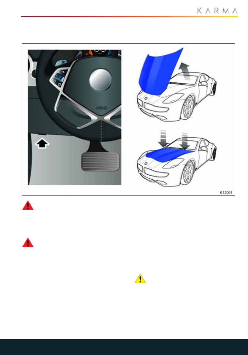
105
HOOD
Hood
OPENING AND CLOSING THE
HOOD
WARNING: Never work on a vehicle
that is plugged in. Always remember
to unplug the vehicle before working under
the hood or the underside of the vehicle.
OPENING THE HOOD
WARNING: Make sure that the hood
is in the fully open position before
working in the engine compartment. In
windy conditions, you may need to secure
the hood to prevent the hood from being
closed by the wind.
1. Pull the (recessed) hood release handle,
located on the lower edge of the
dashboard closing panel.
2. Raise the hood.
3. Ensure the hood is in the fully open
position.
CLOSING THE HOOD
1. Lower the hood to the closed position.
2. Press down firmly on each side of the
hood (see illustration) to engage the
locks.
Note: You will hear the locks click into
place.
CAUTION: Before driving, check that
the locks on both sides of the hood are
fully engaged by attempting to lift the
hood. There should be no movement.
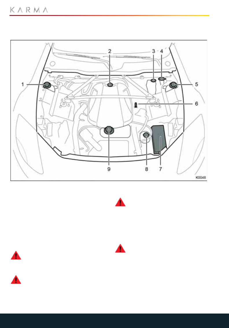
106
ENGINE COMPARTMENT
Engine Compartment
ENGINE COMPARTMENT
OVERVIEW
1. Coolant reservoir - Electric drive
components
2. Engine oil filler cap
3. Brake fluid reservoir
4. Windshield washer reservoir
5. Coolant reservoir - Engine
6. Engine oil level dipstick
7. Engine compartment fuse box
8. Power steering reservoir
9. Coolant reservoir - Battery
WARNING: Before working in the
engine compartment, ensure that
the vehicle is OFF and the key fob is outside
the vehicle.
WARNING: Your Revero uses high
voltage. System components can be
hot to touch during and after starting and
when the vehicle is shut off. Be careful of
both the high voltage and the high
temperature. Obey all labels that are
attached to the vehicle.
WARNING: The vehicle’s high voltage
system has no user serviceable
parts. Disassembling, removing or
replacing high voltage components, cables
or connectors can cause severe burns or
electric shock that may result in serious
injury or death. High voltage cables are
colored orange for easy identification.
WARNING: Battery posts, terminals,
and related accessories contain lead
and lead compounds, chemicals known to
the State of California to cause cancer and
birth defects or other reproductive harm.
Batteries also contain other chemicals
known to the State of California to cause
cancer. WASH HANDS AFTER HANDLING.
See California Proposition 65 Warning
0227.
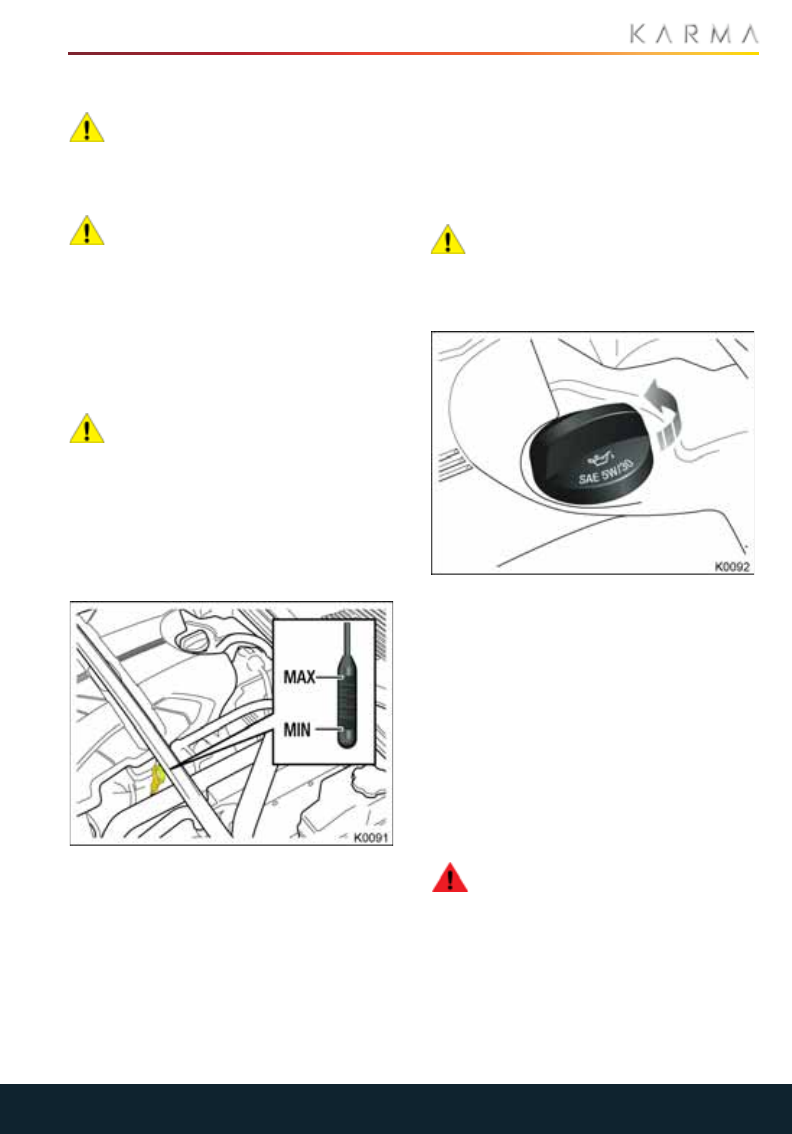
107
ENGINE COMPARTMENT
ENGINE OIL
CAUTION: It is recommended that the
oil level is checked monthly. If any
significant or sudden drop in oil level is
noted, seek qualified assistance
immediately.
CAUTION: Your Revero’s warranty
may be invalidated if damage is
caused by the use of improper engine oil.
Low quality or obsolete oils do not provide
the protection required by modern, high
performance engines. Failure to use an oil
that meets the required specification could
cause excessive engine wear, a buildup of
sludge and deposits and increased
pollution. It could also lead to engine failure.
CAUTION: Do not use oil additives of
any type, as engine damage could
occur. Use only specified lubricants.
CHECKING THE OIL LEVEL
Note: If it is necessary to check the oil level
when the engine is hot, switch off the
vehicle and let it stand for five minutes to
allow the oil to drain back into the sump.
1. Withdraw the dipstick and wipe the
blade clean with a lint free cloth.
2. Fully re-insert the dipstick and
withdraw again to check the oil level.
Never allow the oil level to fall below the
lower mark on the dipstick.
As a general guide, if the level on the
dipstick:
•Is nearer to the upper mark, add no oil.
•Is nearer to the lower mark than the
upper, add one pint (half a liter) of oil.
•Is below the lower mark, add two pints
(one liter) of oil and re-check the level
after a further five minutes.
ADDING ENGINE OIL
CAUTION: Overfilling with oil could
result in severe engine damage. Oil
should be added in small quantities and the
level re-checked to ensure that the engine
is not overfilled.
1. Unscrew the oil filler cap.
2. Add the recommended engine oil to
maintain the level between the MIN and
MAX marks on the dipstick. See
“Approved Fluids and Capacities” on
page 112.
3. Check the oil level again after five
minutes.
4. Once the correct level is achieved,
replace the filler cap and securely
tighten by hand.
5. Clean up any oil spilled during topping-
up.
WARNING: Engine oil contains
chemicals known to the State of
California to cause cancer and birth
defects or other reproductive harm. WASH
HANDS AFTER HANDLING. See California
Proposition 65 Warning 0227.
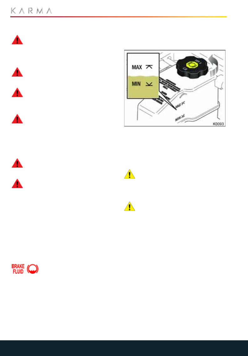
108
ENGINE COMPARTMENT
BRAKE FLUID
WARNING: Brake fluid is highly toxic
- keep containers sealed and out of
the reach of children. If accidental
consumption of fluid is suspected, seek
medical attention immediately.
WARNING: If the fluid comes into
contact with the skin or eyes, rinse
immediately with plenty of water.
WARNING: Brake fluid is highly
flammable. Do not allow brake fluid
to come into contact with open flames or
other sources of ignition (e.g. a hot engine).
WARNING: Seek qualified assistance
immediately if brake pedal travel is
unusually long or if there is any significant
loss of brake fluid. Driving under such
conditions could result in extended
stopping distances or complete brake
failure.
WARNING: Do not drive the vehicle
with the fluid level below the MIN
mark.
WARNING: Brake fluid contains
chemicals known to the State of
California to cause cancer and birth
defects or other reproductive harm. WASH
HANDS AFTER HANDLING.See California
Proposition 65 Warning 0227.
Check the fluid level monthly. The level
should be checked more frequently in high
mileage conditions.
The fluid level may drop slightly during
normal use, as a result of brake pad wear,
but should not be allowed to drop below
the MIN mark.
If the quantity of fluid in the
brake reservoir drops below
the recommended level, an
indicator lamp in the DIS will illuminate.
Note: If the indicator lamp illuminates while
the vehicle is being driven, stop the vehicle
as soon as safety permits by gently
applying the brakes. Check and fill the fluid
reservoir if necessary.
CHECKING THE FLUID LEVEL
Check the fluid level with the vehicle
standing on level ground.
The level of fluid can be seen through the
translucent body of the reservoir. The fluid
level should be between the MIN and the
MAX marks.
FILLING UP THE BRAKE RESERVOIR
CAUTION: Brake fluid will damage
painted surface. Soak up any spillage
with an absorbent cloth immediately and
wash the area with a mixture of car
shampoo and water.
CAUTION: Only use new fluid from an
airtight container. Fluid from open
containers, or fluid previously bled from the
system, will have absorbed moisture, which
will adversely affect performance, and
must not be used.
1. Clean the filler cap with a clean, dry
cloth before removing, to prevent dirt or
moisture from entering the reservoir.
2. Remove the filler cap.
3. Fill the reservoir using an approved
brake fluid until the fluid level is
between the MIN and MAX marks. See
“Approved Fluids and Capacities” on
page 112.
4. Replace the filler cap.
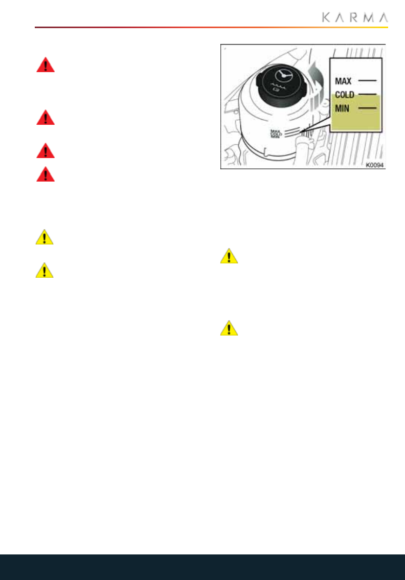
109
ENGINE COMPARTMENT
POWER STEERING FLUID
WARNING: Power steering fluid is
highly toxic - keep containers sealed
and out of reach of children. If accidental
consumption of fluid is suspected, seek
medical attention immediately.
WARNING: If the fluid comes into
contact with the skin or eyes, rinse
immediately with plenty of water.
WARNING: Do not spill the fluid onto
a hot engine - a fire may result.
WARNING: Power steering fluid
contains chemicals known to the
State of California to cause cancer and
birth defects or other reproductive harm.
WASH HANDS AFTER HANDLING. See
California Proposition 65 Warning 0227.
CAUTION: Seek qualified assistance
immediately if there is a sudden
noticeable drop in the fluid level.
CAUTION: If fluid loss is slow, the
reservoir may be filled to the upper
level mark to enable the vehicle to be
driven to a repair facility for inspection.
However, we do recommend you seek
qualified assistance before driving the
vehicle.
CHECKING THE FLUID LEVEL
Check the fluid with the vehicle OFF,
standing on level ground and the system
cold. Ensure that the steering wheel is not
turned after stopping the engine.
The level of fluid can be seen through the
translucent body of the reservoir. The fluid
level should be between the MIN and the
MAX marks.
FILLING UP THE POWER STEERING
RESERVOIR
CAUTION: It is imperative that the
steering system does not become
contaminated in any way. Always use new
fluid and clean the area around the filler
neck, both before removing the filler cap
and after topping up. Never return drained
fluid to the system.
CAUTION: Power steering fluid will
damage painted surfaces. Soak up
any spillage with an absorbent cloth
immediately and wash the area with a
mixture of car shampoo and water.
1. Clean the filler cap before removing to
prevent dirt from entering the reservoir.
2. Remove the filler cap.
3. Fill the reservoir using an approved
power steering fluid until the fluid level
is between the MIN and MAX marks.
See “Approved Fluids and Capacities”
on page 112.
4. Replace the filler cap.
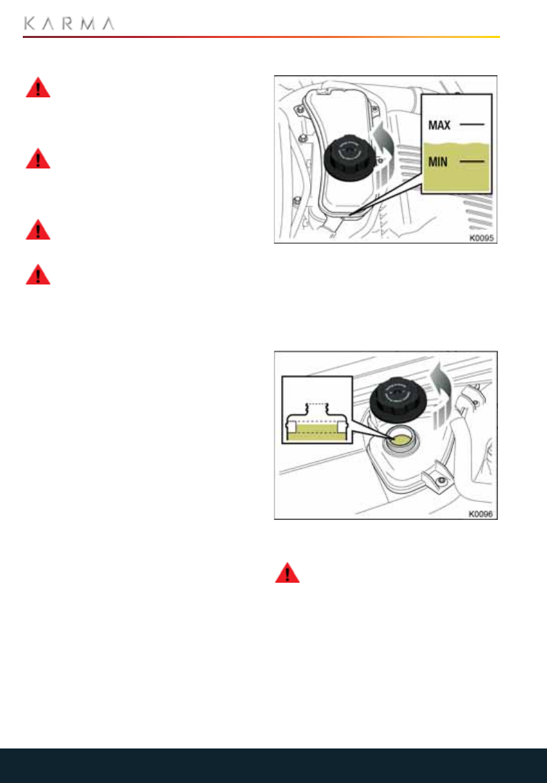
110
ENGINE COMPARTMENT
COOLANT
WARNING: Never remove filler caps
when the system is hot, as the
reservoir will be pressurized. Coolant and
steam can escape rapidly when the cap is
removed, causing injury.
WARNING: Antifreeze is highly
flammable. Do not allow antifreeze
to come into contact with open flames or
other sources of ignition (e.g. a hot engine)
- a fire may result.
WARNING: Unscrew the filler cap
slowly, allowing the pressure to
escape before removing completely.
WARNING: Engine coolant contains
chemicals known to the State of
California to cause cancer and birth
defects or other reproductive harm. WASH
HANDS AFTER HANDLING. See California
Proposition 65 Warning 0227.
Your Revero is unique in that unlike a
traditional vehicle, it has three separate
cooling systems to cool the engine, electric
drive components and the high voltage
battery.
The coolant levels for each reservoir should
be checked monthly. The levels should be
checked more frequently in high mileage
conditions. Always check the level when the
system is cold.
The coolant levels for the low temperature
and the high temperature reservoir bottles
should be filled to the molded tab seen
inside the bottle.
BATTERY COOLANT LEVEL
The level of fluid can be seen through the
translucent body of the reservoir. The fluid
level should be between the MIN and the
MAX marks.
ELECTRIC DRIVE COMPONENTS AND
THE ENGINE COOLANT LEVELS
To check the coolant level, the filler cap
must be removed.
WARNING: Place your hand on the
lid of the coolant reservoir. If it feels
hot to the touch, do not attempt to open
the container. Severe burns may result.
Only proceed to open the container if the
container is warm to the touch.
The level of fluid must be in the mid level of
the molded tab. If the level of coolant falls
below the tab, the system must be filled
with the approved coolant specified by
Karma.
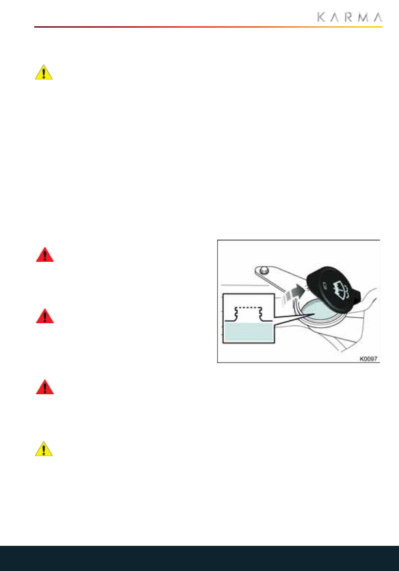
111
ENGINE COMPARTMENT
FILLING UP THE COOLANT
RESERVOIRS
CAUTION: If persistent coolant loss is
noticed, seek qualified assistance
immediately.
Fill the reservoir to the upper level indicator
mark using only a 50% mix of water and
approved antifreeze. See “Approved Fluids
and Capacities” on page 112.
Note: In an emergency, and only if the
approved antifreeze is unavailable, fill the
cooling system with clean water, but be
aware of the resultant reduction in freeze
protection.
Ensure the cap is tightened fully after
refilling is complete by turning the cap until
the ratchet cap clicks.
WASHER FLUID
WARNING: Some windshield washer
products are flammable, particularly
in undiluted concentrations. Do not allow
windshield washer fluid to come into
contact with open flames or sources of
ignition.
WARNING: If the vehicle is operated
in temperatures below 4°C (40°F),
use a washer fluid with frost protection. In
cold weather, failure to use a windshield
washer fluid with frost protection could
result in impaired vision and an unsafe
driving condition.
WARNING: Washer fluid contains
chemicals known to the State of
California to cause cancer and birth
defects or other reproductive harm. WASH
HANDS AFTER HANDLING. See California
Proposition 65 Warning 0227.
CAUTION: Body panels may suffer
discoloration as a result of windshield
washer fluid spillage. Take care to avoid
spillage, particularly if an undiluted or high
concentration is being used. If spillage
occurs, wash the affected area
immediately with water.
The washer reservoir supplies both the
windshield and headlamp washer jets.
Check and fill up the reservoir level monthly
or more frequently in high use conditions.
If the quantity of fluid remaining in the
washer reservoir drops to less than one
liter, a message will be displayed on the
touchscreen diagnostic screen.
Operate the washers periodically to check
that the nozzles are clear and properly
directed.
FILLING UP THE WASHER RESERVOIR
Note: National or local regulations may
restrict the use of Volatile Organic
Compounds (VOCs) which are commonly
used as antifreeze agents in washer fluid. A
washer fluid with limited VOC content
should be used only if it provides adequate
freeze resistance for all climates in which
the vehicle is operated.
1. Clean the filler cap before opening to
prevent dirt from entering the reservoir.
2. Open the filler cap.
3. Fill the reservoir with an approved fluid
until the fluid is visible just below the
filler neck. In cold climates, always fill up
with windshield washer fluid to prevent
freezing.
4. Install the filler cap.

112
ENGINE COMPARTMENT
APPROVED FLUIDS AND CAPACITIES
Fluid Specification Capacity
Engine oil
SAE 5W/30 meeting specification Dexos II, ACEA A5,
ILSAC GF-5 or API SN/Resource Conserving.
Karma Automotive recommends Mobil 1 AFE 0W30.
5 qt
(4.7 liters)
Brake fluid
You must use CCI B070 type brake fluid. You can
request either Karma P/N C131125610000 or GM P/N
88863461.
1.6 qt
(1.5 liters)
Power steering fluid Pentosin CHF11S or CHF202 1.8 qt
(1.7 liters)
Coolant - Engine
50/50 mix of DEX-COOL Extended life Antifreeze and
clean drinkable water - preferably distilled water.
Karma Automotive recommends Havoline DEX-
COOL or a coolant meeting specification GM 6277M.
12.7 qt
(12.0 liters)
Coolant - Battery
50/50 mix of DEX-COOL Extended life Antifreeze and
clean drinkable water - preferably distilled water.
Karma Automotive recommends Havoline DEX-
COOL or a coolant meeting specification GM 6277M.
3.7 qt
(3.5 liters)
Coolant - Electric
drive components
50/50 mix of DEX-COOL Extended life Antifreeze and
clean drinkable water - preferably distilled water.
Karma Automotive recommends Havoline DEX-
COOL or a coolant meeting specification GM 6277M.
12.7 qt
(12.0 liters)
Washer fluid Any good quality windshield washer fluid. 4.5 qt
(4.3 liters)
A/C Refrigerant
R134a.
Karma Automotive recommends KLEA 134a
refrigerant.
Note: If any oil needs adding to the system, only use
an oil meeting ND 11 specification.
1.41 lb.
(0.64 kg)
Differential oil 75W/90 synthetic axle lubricant meeting
specification GM 9986115.
2.6 qt
(2.5 liters)
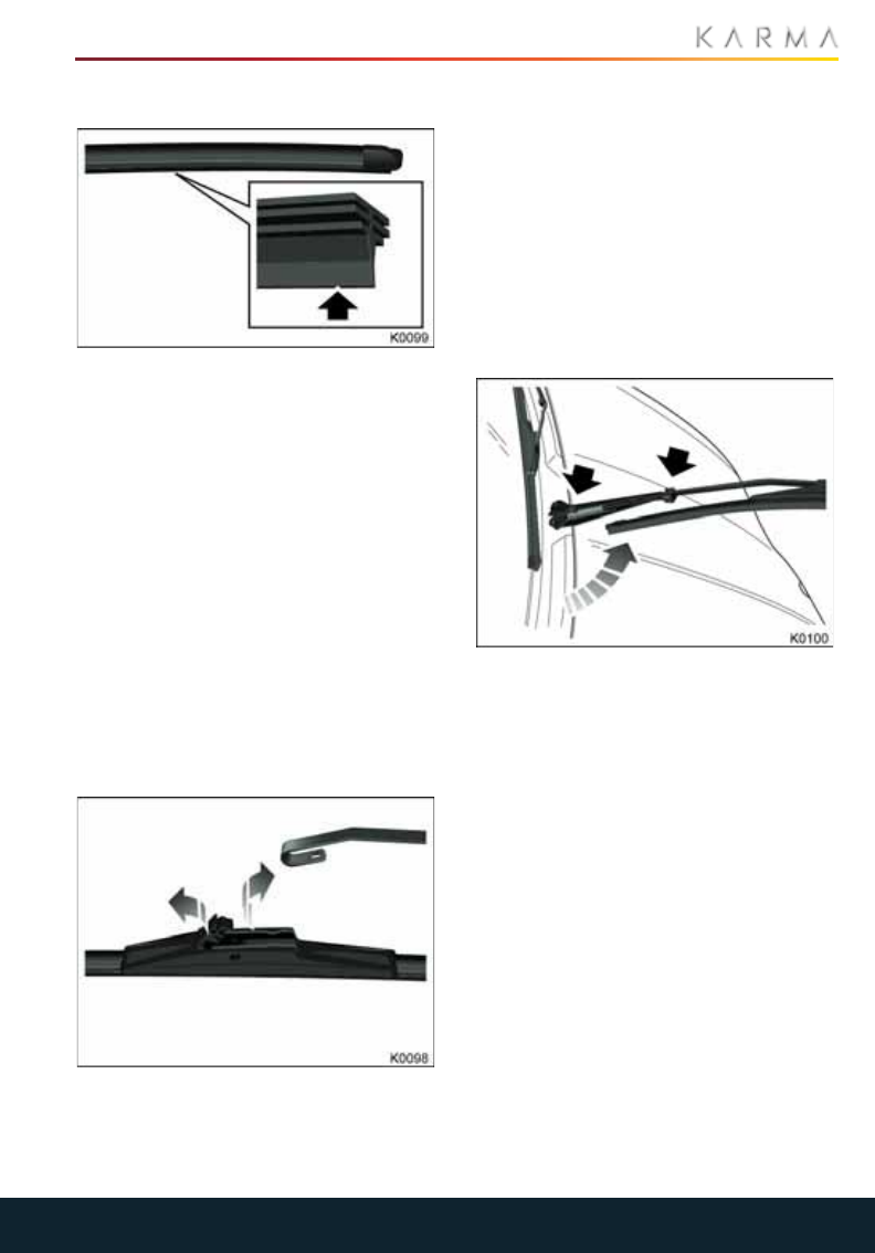
113
WIPERS AND WASHERS
Wipers and Washers
CHECKING THE WIPER BLADES
Only use cleaning products which have
been approved for use on automotive glass
and rubber. Inappropriate products may
cause damage.
Periodically check and clean the wiping
edge of the wiper blade. Clean the blade
edge by wiping with a soft cloth or sponge,
using warm soapy water.
Also, check the blade rubber for cracks,
splits and roughness. If any damage is
found, replace the blade immediately to
prevent damage to the glass.
REPLACING THE WIPER BLADES
Replace the wiper blades if they are worn
or damaged. Damage can be caused by
extreme dusty conditions, sand, salt, heat,
sun, snow, and ice.
1. Release the locking lever securing the
wiper blade to the wiper arm.
2. Lift the wiper arm away from the
windshield.
3. Squeeze the locking feature on the
blade to allow removal of the wiper
blade.
4. Slide the wiper blade from the wiper
arm and remove.
To install the new blade, position the new
assembly on the wiper arm and close the
locking lever to retain the wiper blade.
Make sure the locking lever is securely
closed.
WASHERS
If a windshield washer becomes blocked,
use a thin strand of wire to clear any
blockages from the nozzle.
Note: The headlamp washers operate with
every fifth operation of the windshield
washer. If you have any problems with the
headlamp washers, please consult a local
Karma Service Provider.
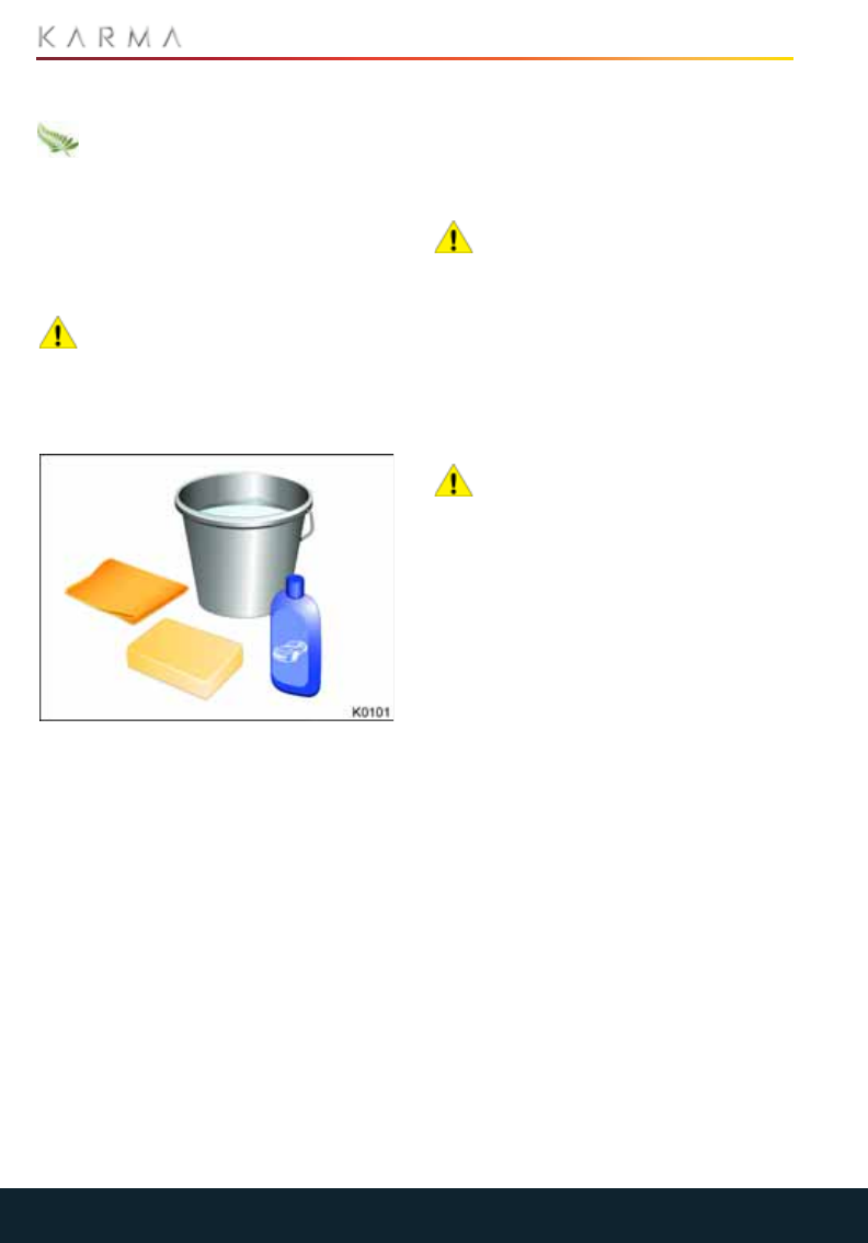
114
CLEANING AND VEHICLE CARE
Cleaning and Vehicle Care
CLEANING THE EXTERIOR
It is illegal to pollute drains, rivers and
waterways. Some cleaning products
contain chemicals that are hazardous to
the environment. Used toxic chemicals
must be disposed of at authorized waste
disposal sites only. Always take
precautions to prevent fluids from spilling.
HAND WASHING
CAUTION: Avoid using tight-napped
or rough cloths, such as washing
mitts. Care must be taken when removing
caked-on dirt or other foreign substances
so the paint surface is not scratched or
damaged.
In order to maintain the appearance of
your vehicle, observe the following:
•Do not wash the vehicle using hot water.
•Do not use detergents or dish washing
liquid.
•In hot weather, do not wash the vehicle
in direct sunlight.
•Do not aim water hoses directly at
window, door or hood seals, or through
wheel apertures onto brake
components.
Use a hose to flush grime and grit from the
bodywork before washing.
Only wash the bodywork using cold or
lukewarm water containing a good quality
wash and wax shampoo.
After washing, rinse with clean water and
thoroughly wipe dry with a chamois. Do not
allow cleaning agents to dry on the finish.
AUTOMATIC CAR WASHERS OR
PRESSURE WASHER
CAUTION: Karma Automotive
recommends that you hand wash
your vehicle. Do not use an automatic car
washer or pressure washer as these may
damage your vehicle’s paint finish, solar
roof, or other components.
Note: Vehicle or paint damage caused by
using an automatic car washer will not be
covered under the vehicle warranty.
WHEELS
CAUTION: Do not use chemical based
wheel cleaners or chrome polish
compounds, as these can damage the
finish of the wheel.
Clean with warm, fresh water containing a
good quality wash and wax shampoo.
Thoroughly rinse the wheels to remove any
residue.
CLEANING THE UNDERSIDE
During winter months if salt has been used
on the roads, use a hose to wash the
underside of the car. Flush away
accumulations of mud in those areas
where debris easily collects (wheel arches
and panel seams, for example).
REMOVING TAR SPOTS
Use denatured alcohol to remove tar spots
and stubborn grease stains from paint.
After cleaning, immediately wash the area
with soapy water to remove all traces of
alcohol.

115
CLEANING AND VEHICLE CARE
CLEANING THE SOLAR ROOF
Clean the solar roof with a soft cloth and a
mild solution of soap and water, or car
shampoo. Do not scrape the glass or use
any abrasive cleaning fluid.
If you notice any damage on the solar roof,
please contact your local Karma Service
Provider for advice.
UNDERHOOD CLEANING
CAUTION: Never use a pressure
washer or a steam cleaner to clean
components in the engine compartment,
as it may damage critical seals on high
voltage electrical components.
Note: Vehicle or paint damage caused by
using a pressure washer will not be
covered under the vehicle warranty.
POLISHING THE BODY
CAUTION: Do not use cutting pastes,
color restoration compounds, or
polishes containing harsh abrasives. These
can scratch the surface and permanently
damage the paintwork.
CAUTION: Chrome polish, or other
abrasive cleaners, must not be used
on the vehicle's brightwork.
To preserve the cosmetic appearance of
the body, occasionally treat the paint
surfaces with an approved polish
containing the following properties:
•Very mild abrasive to remove surface
contamination without removing or
damaging the paint.
•Filling compounds that will fill scratches
and reduce their visibility.
•Wax to provide a protective coating
between the paint and the elements.
PAINT DAMAGE AND REPAIR
Regularly inspect the paintwork for
damage. Any stone chips, fractures or
deep scratches in the paint/bodywork
should be repaired promptly. Bare metal
will corrode quickly, and if left untreated,
can result in expensive repairs.
Treat chips and scratches to the paint
using a paint touch-up pen. Use the touch-
up pen after washing but before polishing
or waxing.
More extensive repairs to the body should
only be carried out by a facility approved
by Karma Automotive. Contact your local
Karma Service Provider for a list of
approved body repair facilities.
USING A CAR COVER
CAUTION: Never use a car cover
when the vehicle is plugged in, doing
so can prevent the battery from being
adequately cooled during charging.
To preserve the cosmetic appearance of
the body when the vehicle is not being
used, you may want to use a car cover.
Only a Karma Automotive approved car
cover should be used.
CLEANING THE INTERIOR
GENERAL CLEANING
CAUTION: Avoid using solvents
(including alcohol), bleach, citrus,
naphtha, silicone based products or
additives on interior components as these
can damage the appearance of the
material.
To maintain the look and appearance of
the interior of your vehicle, the interior
should be inspected and cleaned
frequently.
It is recommended that for general
cleaning, materials and surfaces should be
cleaned using a non solvent based cleaning
(wet) wipe (e.g. a baby wipe), and a
microfiber cloth.
If possible, try to wipe up spillages and
clean marks as they happen. This will
reduce the need for more expensive
cleaning in the future.
Note: It is advisable to test all cleaners on a
concealed area before use.

116
CLEANING AND VEHICLE CARE
GLASS AND MIRRORS
The windshield, rear window and mirror
glass should only be cleaned using soapy
water and a soft cloth. This will avoid
damaging the reflective surface of the
mirror and heating elements in the rear
window.
CLEANING THE DIS AND CIU SCREENS
The DIS coverglass has an anti-reflective
coating, and should be treated with care.
Abuse of the glass may result in removal of
the coating, abnormal color uniformity,
scratches, or cracks.
The safest way to clean the glass is with a
clean microfiber cloth and water.
Note: Windex comes is different varieties.
Pay attention to the ammonia content.
AIR BAG MODULE COVERS
WARNING: Air bag covers should
only be cleaned using a slightly
dampened cloth/cleaning wipe. Any
substance which enters the air bag could
prevent correct deployment.
WARNING: Any damage, or cracks
on an air bag cover should be
referred to a Karma Service Provider for
inspection.
PLASTIC MATERIALS
Clean heavily soiled plastic surfaces using
warm water and a non-detergent soap,
then wipe clean with a soft cloth.
CHROME/METAL SURFACES
CAUTION: Do not use metal polish,
abrasive cleaners or hard cloths to
clean chrome/metal surfaces as these can
damage the surface finish.
Clean chrome surfaces using a soft cloth,
warm water and a non-detergent soap.
Wipe the surface dry using a microfiber
cleaning cloth.
Lightly polish the surface using a spray
furniture polish applied with a soft cloth.
Polish using a linear motion along the
surface and do not press too hard.
LEATHER
CAUTION: Some materials/fabrics
are prone to dye-transfer which can
cause discoloration of lighter colored
leathers. Affected areas should be cleaned
as soon as possible using a cleaning wipe
(such as a baby wipe).
To prevent ingrained dirt and staining,
inspect the seat upholstery regularly and
clean every one to two months, as follows:
•Wipe off fine dust from the seat
surfaces using a clean, damp, non-
colored cloth. Change frequently to a
clean area of cloth, to avoid abrasive
action on the leather surface. Avoid
over-wetting.
•If this is not sufficient, use a non solvent
based cleaning wipe containing aloe or
lanolin (such as a baby wipe).
Note: Using soap or commercially
available leather cleaners/conditioners
is not recommended as this will dry out
the leather.
CARPETS
Clean with warm water and a non-
detergent soap. Avoid over-wetting the
area.
For heavily soiled areas, use a diluted
upholstery cleaner.
SEAT BELTS
WARNING: Do not allow any water,
cleaners, or fabric from cloths to
enter the seat belt mechanism. Any
substance which enters the mechanism
may affect the performance of the seat
belt in an impact.
Extend the belts and clean with warm,
soapy, fresh water only. Do not use any
type of detergent or chemical cleaning
agent. Allow the belts to dry naturally while
extended, preferably away from direct
sunlight.

117
CLEANING AND VEHICLE CARE
TOUCHSCREEN AND DIS
Clean the touchscreen and DIS using a
damp cloth/cleaning wipe. Do not use
cleaning compounds or solutions.
FLOOR MATS
WARNING: To avoid potential pedal
interference that may result in a
collision or injury, ensure that the driver’s
floor mat is securely retained.
WARNING: Never place another
floor mat on top of the driver’s floor
mat.
The use of genuine Karma floor mats can
extend the life of your Revero carpet and
make it easier to clean the interior. Mats
should be maintained with regular cleaning
and replaced if they become excessively
worn.
1. To remove the floor mats, lift up on the
polished lock buttons on the floor mats
while lifting up the rear mat section.
2. Maneuver the floor mat to release it
form the floor hook.
REINSTALLATION
1. Slide floor mat in and lock the mat to the
upper floor hook behind the brake
pedal.
2. Lower the rear section and press the
polished lock buttons unto their pins.
VEHICLE STORAGE
WARNING: Always wear
appropriate eye protection when
working with the 12-volt battery. The
battery contains acid, which is both
corrosive and poisonous.
WARNING: During normal use, the
12-volt battery emits explosive
hydrogen gas - ensure sparks and naked
lights are kept away from the battery.
WARNING: Battery posts, terminals,
and related accessories contain lead
and lead compounds, chemicals known to
the State of California to cause cancer and
birth defects or other reproductive harm.
Batteries also contain other chemicals
known to the State of California to cause
cancer. WASH HANDS AFTER HANDLING.
See California Proposition 65 Warning
0227.
BEFORE STORING THE VEHICLE
WARNING: Battery posts, terminals,
and related accessories contain lead
and lead compounds, chemicals known to
the State of California to cause cancer and
birth defects or other reproductive harm.
Batteries also contain other chemicals
known to the State of California to cause
cancer. WASH HANDS AFTER HANDLING.
See California Proposition 65 Warning
0227.
1. Store the vehicle with the high voltage
battery with a minimum 20 mile EV
range.
2. The vehicle can be connected to an
external 110v/220v charger during
storage. The charger will automatically
shut off when the HV battery is fully
charged.
3. Store the vehicle in an environment
between 14°F (-10°C) and 122°F (50°C).
Storing the vehicle at extreme
temperatures can cause damage to the
high voltage and 12 volt batteries and
should be avoided.
4. Inflate the tires to 45 psi for storage
purposes only. This will help reduce flat
spots from developing.
WARNING: Over-inflating a tire
could cause the tire to rupture and
you or others could be injured. Be sure to
read and follow the tire sealant and
compressor kit instructions and inflate the
tire to its recommended pressure. Do not
exceed the recommended pressure.
1. Verify mechanical keys will unlock and
open the passenger side door using the
mechanical lock.

118
CLEANING AND VEHICLE CARE
Note: If the 12 volt battery becomes
discharged, the only way to open the doors
will be to use the mechanical lock cylinder
on the passenger side front door.
1. Place the vehicle in Park [P] and DO
NOT apply the parking brake.
2. Turn the HVAC system ON for five
minutes and set the vent setting to
Recirculation mode. This will fully
lubricate the seals and internal
components and prevent dust from
being able to enter the passenger
compartment.
3. Make sure the windows are closed and
turn Off the HVAC system.
4. Verify the key FOBs are not in the
vehicle.
5. Press the Start/Stop button to take the
vehicle out of system Ready mode and
power down the high voltage system.
6. Wait for car to go to sleep,
approximately 1 minute.
7. Connect an approved Absorbed Glass
Mat (AGM) compatible battery
maintainer to prevent it from
discharging.
Note: Standard battery maintainers can
overcharge and cause damage to the 12
volt AGM battery used in the Karma and
shorten its lifespan.
STORING A VEHICLE FOR LONGER
THAN FOUR WEEKS
If storing for two weeks or less,
disconnecting the 12 volt auxiliary battery is
not necessary.
Long-term storage over three weeks will
require the 12 volt battery and solar panel
fuse to be disconnected.
A battery maintainer is required to
maintain the 12 volt battery voltage.
Standard battery maintainers can
overcharge and cause damage to the 12
volt AGM battery used in the Karma and
shorten its lifespan.
In preparation for storage, it is
recommended that the HVAC system is
turned ON for five minutes and set the vent
setting to Recirculation mode. This will fully
lubricate the seals and internal
components and prevent dust from being
able to enter the passenger compartment.
Note: If storing for two weeks or less,
disconnecting the 12 volt auxiliary battery is
not necessary.
1. Inflate the tires to 45 psi for storage
purposes only. This will help reduce flat
spots form developing.
2. Verify mechanical keys will unlock and
open the passenger side door using the
mechanical lock.
Note: If the 12 volt battery becomes
discharged, the only way to open the doors
will be to use the mechanical lock cylinder
on the passenger side front door.
1. Place the vehicle in Park [P] and DO
NOT apply the parking brake.
2. Turn the HVAC system ON for five
minutes and set the vent setting to
Recirculation mode.
3. Make sure the windows are closed and
turn Off the HVAC system.
4. Verify the key FOBs are not in the
vehicle.
5. Press the Start/Stop button to take the
vehicle out of system Ready mode and
power down the high voltage system.
6. Wait for car to go to sleep,
approximately 1 minute.
7. Disconnect the 12 volt battery negative
(-) cable connector under the hood to
prevent the battery from becoming
discharged.
8. Disconnect the Solar Roof fuse #10
from the engine compartment fuse
panel.
9. Disconnect the 12 volt main connector
located under the hood, on right fender.
10. Wait 30 seconds.
11. Connect an approved AGM compatible
battery maintainer to prevent it from
discharging.

119
CLEANING AND VEHICLE CARE
Note: Standard battery maintainers can
overcharge and cause damage to the 12
volt AGM battery used in the Karma and
shorten its lifespan.
BRINGING THE VEHICLE OUT OF
STORAGE
1. You may need to use the mechanical
key to open the right front door to gain
entry into the vehicle.
2. Open the hood and reconnect the
negative (-) 12 volt battery cable.
3. Connect a high voltage charger if
necessary to bring the high voltage
battery to a 20 mile range.
4. Depress the brake pedal and press the
Start/Stop button to place the vehicle in
system Ready mode.
Note: If the HV battery SOC is low or if the
12 volt battery has been disconnected, the
engine may start to maintain the HV
battery SOC or for normal diagnostic
purposes. Ensure there is enough fuel in the
gas tank to run for 30 minutes and that the
storage location is properly ventilated.
1. Keep the vehicle in system Ready mode
for 30 minutes to charge the 12 volt
auxiliary battery.
2. Calibrate the parking brake by applying
and then releasing the parking brake.
3. Run the Air Conditioning for five
minutes to properly lubricate all
components.
4. Connect the high voltage charge
connector to begin a charge session
until the high voltage battery reaches a
minimum of a 20 mile range.
5. Inflate the tires back to the specified
pressures.
6. Disconnect the high voltage charger.
7. Drive the vehicle, use the brakes
normally; stopping from 30 mph at
least 20 times to prevent rust build up
on the brake rotors and to prevent
unwanted brake vibrations from rust
build up.
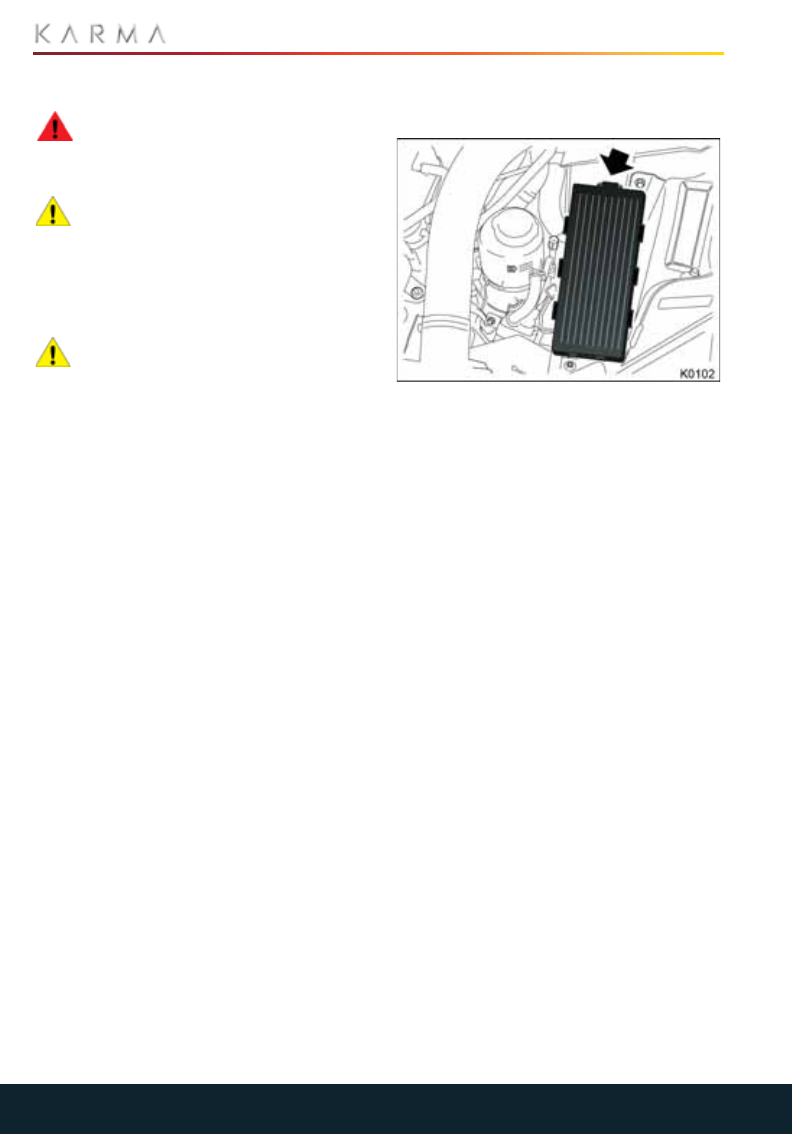
120
FUSES
Fuses
REPLACING A FUSE
WARNING: Always make sure the
affected electrical circuit is switched
off and the vehicle is OFF, before replacing
a fuse.
CAUTION: Only use Karma
Automotive approved replacement
fuses of the same rating and type, or fuses
of matching specification. Using an
incorrect fuse may result in damage to the
vehicle’s electrical system and can result in
a fireCAUTION: If the replacement fuse
blows after installation, the system
should be checked by Karma Automotive
or your local Karma Service Provider.
Identify the fuse protecting the affected
circuit - using the label on the inside of the
fuse box cover, or as shown on the
following pages - and pull to remove. A
break in the wire inside the fuse indicates
that the fuse has blown.
Note: Karma Automotive recommends that
owners do not remove or replace relays.
Failure of any of these items should be
investigated by a qualified technician.
ENGINE COMPARTMENT FUSE
BOX
Release the plastic cover by pressing the
tab arrowed.
The fuse values and locations and the
circuits protected are shown on the plastic
cover.
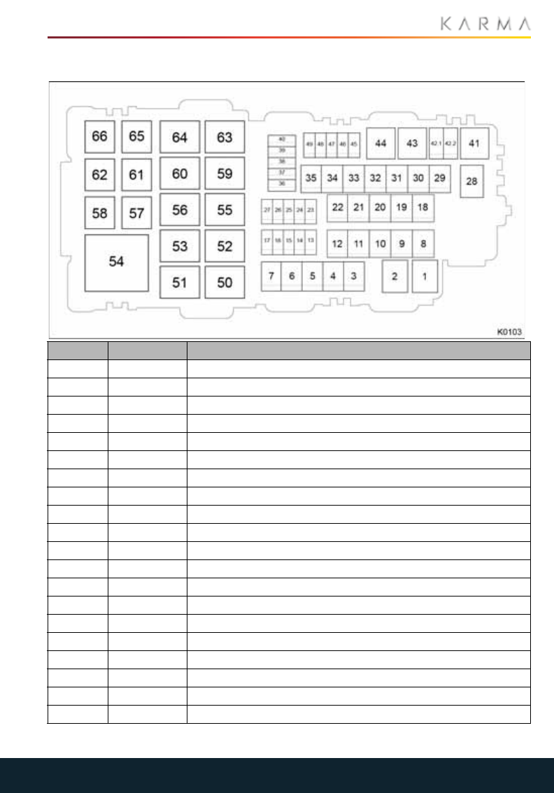
121
FUSES
FUSE SPECIFICATIONS
Fuse Rating Circuit protected
1 50 A Electronic brake control
2 50 A Radiator fan control
3 30 A Windshield wipers
430 ARear window defrost
520 AFuel pump relay
6 30 A Smart window control - right hand side
7 20 A Front power point and front USB
8 30 A Driver’s power seat
9 40 A Power supply KL30 (Body 2)
10 30 A SPBC & HVAC
11 20 A HCU to Coolant pump C
12 30 A Smart window control - left hand side
13 10 A Powertrain
14 30 A Seat module
15 30 A HV Battery (BECM)
16 15 A Airbag module
17 30 A Passenger seat control
18 20 A Coolant pump B - rear
19 50 A High beams & LH, RH door
20 40 A KL 30 Body 1

122
FUSES
21 40 A KL 30 security
22 30 A KL 30 Interior lighting
23 15 A AC, HVAC & PRNDL
24 15 A FT / RR inverter
25 10 A RLY 41, 46
26 10 A HCU feed
27 15 A PT relay feed
28 60 A Antilock Braking System (ABS) EBCM Mot batt feed
29 30 A Antilock Braking System (ABS) EPB module
30 30 A RT chiller fan
31 30 A Main ECM PT R53 feed
32 30 A Rear heated seats
33 20 A Coolant pump A - Rear
34 40 A Amplifier
35 30 A Feeds fuses 40, 45, 46, 47, 49
36 15 A Rly 1 output
37 10 A Rly 2 output
38 20 A Rly 3 output
39 10 A Rly 4 output
40 15 A CIU / TPI
46 15 A INV & OBCM B+
47 10 A PRND, Mirrors, Steering column
48 10 A Cooling pump
49 10 A DIS and diagnostics
Fuse Rating Circuit protected
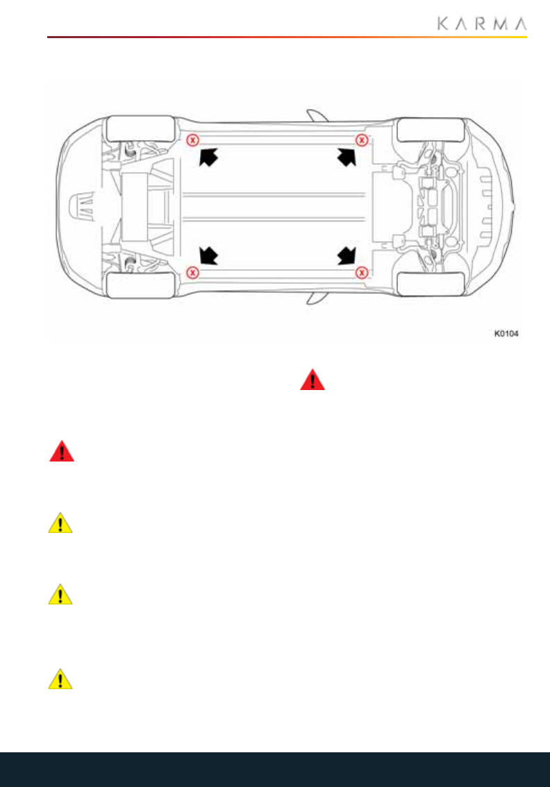
123
RAISING THE VEHICLE
Raising the Vehicle
JACKING AND LIFTING THE VEHICLE
Refer to the illustration above to determine
the correct position for lifting the vehicle
with a jack or on a two post lift.
Please make sure that any non Karma
Automotive repair facility is aware of these
lifting points.
WARNING: Never raise the vehicle
when the charge cable is connected,
even if charging is not in progress. Always
disconnect the charge cable before raising
the vehicle.
CAUTION: These are the only
approved lifting points for your
Revero. Lifting the vehicle at any other
points may cause irreparable damage to
the vehicle.
CAUTION: The coolant lines for the
electric drive system run in channels
recessed into the floor of the vehicle. These
channels are located approximately 2
inches (45 mm) from the lower edge of the
rocker.
CAUTION: Use a suitable rubber or
wood pad to protect the body from
surface damage.
TIRE CHANGING PROCEDURE
WARNING: Lifting a vehicle and
getting under it to do maintenance or
repairs is dangerous without the
appropriate safety equipment and
training.
Changing a tire can be dangerous. The
vehicle can slip off the jack and roll over or
fall causing injury or death. Find a level
place to change the tire. To help prevent
the vehicle from moving:
1. Set the parking brake firmly.
2. Put an automatic transmission in P
(Park) or a manual transmission in 1
(First) or R (Reverse).
3. Turn off the engine and do not restart
while the vehicle is raised.
4. Do not allow passengers to remain in
the vehicle.
5. Place wheel blocks, if equipped, on both
sides of the tire at the opposite corner
of the tire being changed.
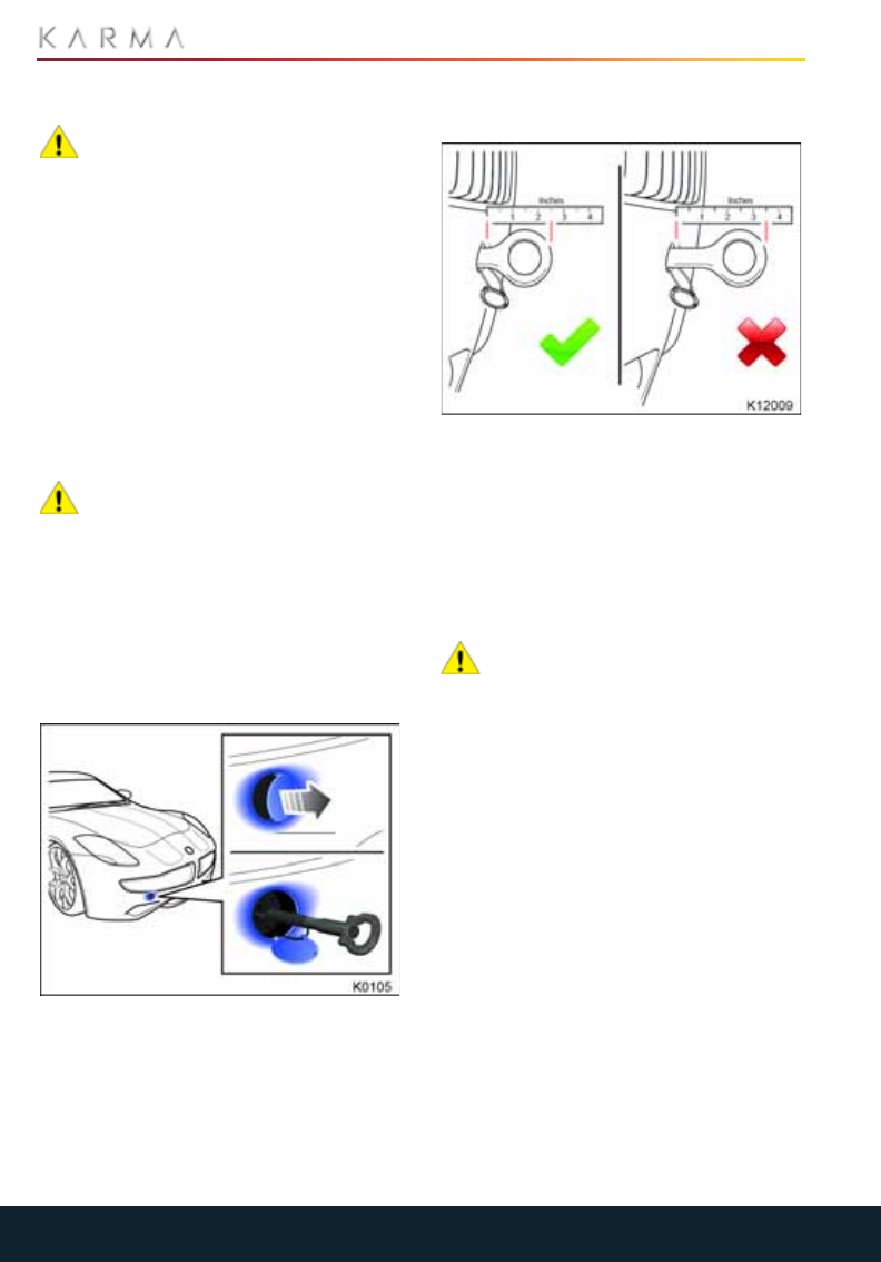
124
VEHICLE RECOVERY
Vehicle Recovery
TRANSPORTING THE VEHICLE
CAUTION: Towing the vehicle with the
wheels on the ground, or on a
suspended lift, may cause serious damage
to the vehicle as well as generating high
voltages in the vehicle’s electrical
components.
The only approved method of towing or
transporting your Revero is using a flatbed
trailer or transporter.
Note: Damage caused by any other towing
method will not be covered by the vehicle
warranty.
ATTACHING THE VEHICLE
RECOVERY EYE
CAUTION: Under no circumstances
should the vehicle be towed using the
vehicle recovery eye. Doing so can cause
significant damage to your Revero.
A vehicle recovery eye can be attached to
the front of the vehicle to allow the vehicle
to be pulled onto a transporter in situations
when the vehicle can roll freely.
The recovery eye is located in the under-
floor storage area of the trunk.
1. Place the vehicle into System Ready
mode.
Note: Severe powertrain damage may
result if you do not place the vehicle into
System Ready mode to release park
lock mechanism in the rear drive unit.
2. Press on the 4 o' clock position of the
cover and it will pop out.
3. Locate the recovery eye through the
bumper and screw into the mount for 10
complete turns. Refer to the illustration
above showing how the recovery eye
should seat into the front of the vehicle.
Note: If the recovery eye cannot be
rotated for 10 complete turns, remove
the recovery eye and clean any debris
from the threads before reinstalling.
CAUTION: Failure to install the
recovery eye correctly could result in
the eye pulling out of the front of the
vehicle, causing significant damage.
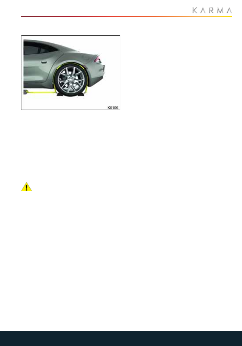
125
VEHICLE RECOVERY
SECURING THE WHEELS
When the vehicle is in position on the
transporter or trailer, use chocks and tie
down straps to secure the wheels.
To a vo id d amag e:
•Ensure that metal parts on tie down
straps do not contact the vehicle’s
painted surfaces or the face of any
wheels.
•Do not place straps over or through the
vehicle’s body panels.
CAUTION: Attaching straps to the
chassis, suspension or other parts of
the body can damage the vehicle.

126
SERVICE INTERVAL SCHEDULES
Service Interval Schedules
SERVICE INTERVAL SCHEDULES
Service interval Service type
Years Distance A B C
1
5,000 mi (8,000 km) ·
10,000 mi (16,000 km) ·
2 20,000 mi (32,000 km) ·
3 30,000 mi (48,000 km) ·
4 40,000 mi (64,000 km) ·
5 50,000 mi (80,000 km) ·
6 60,000 mi (96,000 km) ·
7 70,000 mi (112,000 km) ·
8 80,000 mi (128,000 km) ·
9 90,000 mi (144,000 km) ·
10 100,000 mi (160,000 km) ·

127
SERVICE INTERVAL SCHEDULES
ADDITIONAL PROCEDURES REQUIRED AT SPECIFIC INTERVALS
SERVICE TYPES AND REQUIRED PROCEDURES
Distance Service type
Every 50,000 mi (80,000 km) Replace air filter
Every 50,000 mi (80,000 km) Replace power steering fluid
Every 50,000 mi (80,000 km) Replace differential oil
Every 50,000 mi (80,000 km) or 5 years Replace brake fluid
Every 100,000 mi (160,000 km) Replace spark plugs
Every 150,000 mi (240,000 km) or 5 years Replace coolant
Action Service type
A B C
Engine oil filter R RR
Engine oil R R R
Power steering fluid I I I
Cooling system (hoses & coolant) I I I
All fluid levels I I I
Engine air filter I I I
Cabin filter IIR
Brake pads - front I I I
Brake pads - rear I I I
Brake shoes - parking mechanism I I
Drive axles (halfshafts) I I I
Shocks - front I I I
Shocks - rear I I I

128
SERVICE INTERVAL SCHEDULES
R = Replace component
P = Perform task
I = Inspect component or system
I/C = Inspect and Clean component or
system
Steering, suspension, alignment I I I
Tire inflation P P P
Lubricate body components P P P
Inspect fuel system I
Inspect exhaust system I
Run diagnostics P P P
Tire wear I
Wheel / Hub I/C
Action Service type
A B C

129
WHEELS AND TIRES
Wheels and Tires
TIRE CARE
Inspection and Maintenance..........................................................................................................130
Tire Wear................................................................................................................................................131
Tire Pressures......................................................................................................................................133
Replacement Wheels and Tires..................................................................................................... 134
Driving in Low Ambient Temperatures....................................................................................... 135
Winter Tires and Tire Chains..........................................................................................................135
TIRE PRESSURE MONITORING SYSTEM (TPMS)
Tire Pressure Monitoring System (TPMS)..................................................................................136
TIRE REPAIR KIT
Tire Repair Kit.......................................................................................................................................138
Safety Precautions.............................................................................................................................139
Using the Tire Repair Kit...................................................................................................................139
Using the Compressor........................................................................................................................141
Replacing the Canister/Air Hose Assembly...............................................................................141
TIRE INFORMATION
Tire Markings........................................................................................................................................142
Uniform Tire Quality Grading.........................................................................................................144
Loading the Vehicle............................................................................................................................145
Steps For Determining Correct Load Limit...............................................................................146
GLOSSARY OF TERMS
Wheels and Tires Glossary...............................................................................................................147

130
TIRE CARE
Tire Care
INSPECTION AND
MAINTENANCE
WARNING: The tires should be
regularly checked for wear and to
make sure that there are no cuts, bulges or
exposure of the ply/cord structure. Do not
drive with tires which are worn, damaged
or inflated to the incorrect pressure. The
safety of the vehicle and occupants will be
adversely affected.
WARNING: Poorly maintained and
improperly used tires are dangerous.
WARNING: Overloading the tires can
cause overheating as a result of too
much flexing. There could be a blowout and
a serious crash. See Vehicle Load Limits.
WARNING: Underinflated tires pose
the same danger as overloaded tires.
The resulting crash could cause serious
injury.
WARNING: Check all tires frequently
to maintain the recommended
pressure.
WARNING: Tire pressure should be
checked when the tires are cold.
WARNING: Overinflated tires are
more likely to be cut, punctured, or
broken by a sudden impact — such as when
hitting a pothole.
WARNING: Keep tires at the
recommended pressure.
WARNING: Worn or old tires can
cause a crash. If the tread is badly
worn, replace them.
WARNING: Replace any tires that
have been damaged by impacts with
potholes, curbs, etc.
WARNING: Improperly repaired tires
can cause a crash. Only the dealer or
an authorized tire service center should
repair, replace, dismount, and mount the
tires.
WARNING: Do not spin the tires
excessively (greater than 35 mph
[56 kmh]) on slippery surfaces such as
snow, mud, ice, etc. Excessive spinning may
cause the tires to explode.
The Karma Revero does not use run-flat
tires and does not have a spare tire.
Always consider tire conditions when
driving, and regularly inspect the tread and
side walls for any sign of distortion (bulges),
cuts or wear and adjust air pressures
regularly.
Good driving practice will improve the
mileage you obtain from your tires, and
avoid unnecessary damage.
•Always ensure that the tire pressures
are correctly adjusted.
•Always observe the posted speed limits,
and advisory speeds.
•Avoid pulling away quickly, or hard
acceleration.
•Avoid making fast turns or braking
sharply.
•Avoid potholes and objects in the road.
•Do not run over curbs or hit the tire
against the curb when parking.
CAUTION: Avoid contaminating tires
with vehicle fluids that can cause
damage.
WHEEL ALIGNMENT AND TIRE
BALANCE
Unbalanced wheels (noticeable as
vibration through the steering) may affect
vehicle handling and tire life.
Note: If tire wear is uneven (on one side of
the tire only) or becomes abnormally
excessive, the wheel alignment should be
checked.
TIRE ROTATION
Because your Revero is equipped with
different size tires on the front and rear
wheels, the tires can only be moved from
side to side on the same axle pair (front or
rear).
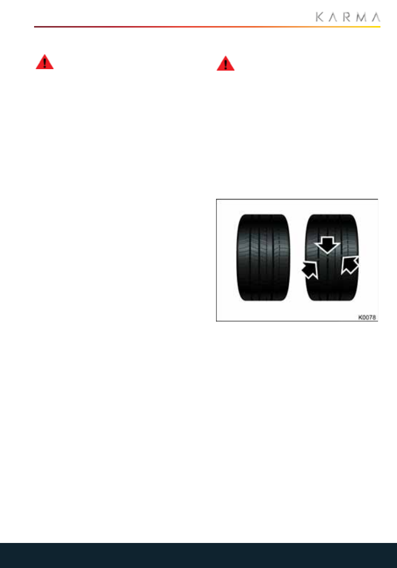
131
TIRE CARE
PUNCTURED TIRES
WARNING: Do not drive the vehicle
with a punctured tire. Even if the
punctured tire has not deflated, it is unsafe
to use as the tire may deflate suddenly at
any time.
Your Revero is equipped with tubeless
tires, which may not leak when penetrated,
provided the object remains in the tire.
If, however, you feel a sudden vibration or
ride disturbance while driving, or you
suspect your tire or vehicle has been
damaged, immediately reduce your speed.
Drive slowly, while avoiding heavy braking
or sharp steering and when safe to do so,
stop the vehicle.
Inspect the tires for damage. If a tire is
under-inflated and does not appear to
have any damage to the sidewall, try to
repair it using the tire repair kit. See “Tire
Repair Kit” on page 138. If you cannot
detect the cause or the tire is too heavily
damaged, have the vehicle towed to a tire
repair center, or your local Karma Service
Provider to have the vehicle inspected.
A puncture will eventually cause the tire to
lose pressure, which is why frequent
checking of tire pressures is important.
Punctured or damaged tires must be
permanently repaired or replaced as soon
as possible.
AGE DEGRADATION
Tires degrade over time due to the effects
of ultraviolet light, extreme temperatures,
high loads, and environmental conditions. It
is recommended that tires are replaced
every six years, but may require
replacement more frequently.
TIRE WEAR
WARNING: The tire wear indicators
show the minimum tread depth
recommended by the tire manufacturer.
Tires which have worn to this point will have
reduced grip and poor water displacement
characteristics.
The tires installed on your Karma are
molded with a high grip compound and
reduced tread depth to improve dry road
traction and handling. The focus on dry
road traction produces a tire that will not
last as long as a general purpose tire.
Drivers should expect significantly shorter
tire life with these tires.
Karma Original Equipment (OE) tires have
wear indicators molded into the tread
pattern.
As the tire tread wears down, the
indicators start appearing at the surface of
the tread, producing the effect of a
continuous band of rubber across the
width of the tire.
A tire must be replaced as soon as an
indicator band becomes visible or the tread
depth reaches the minimum permitted by
legislation.
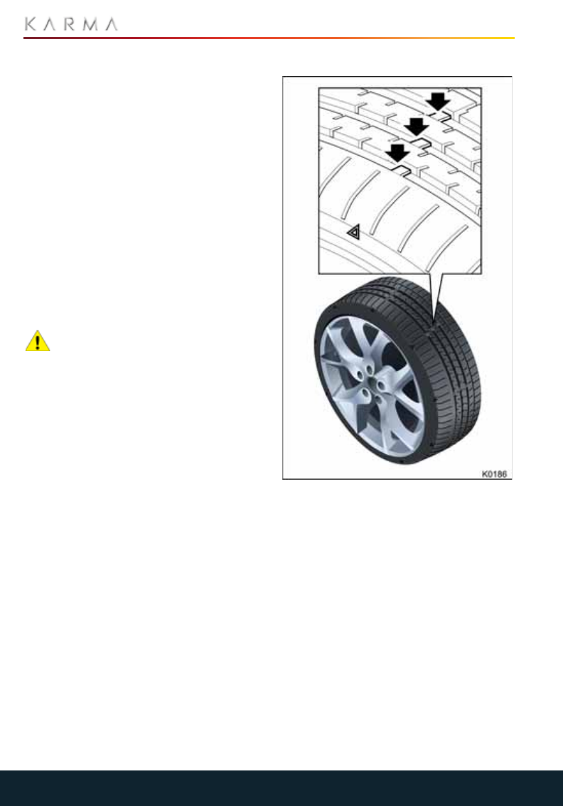
132
TIRE CARE
NORMAL TIRE WEAR
The characteristics for normal tire wear on
the Karma are defined as:
•A uniform thickness of usable rubber
across the entire tread width of the tire.
•The tread depth at the shoulder rib is
reduced compared to the center of the
tire. This helps the Karma achieve
excellent steering and dry road
handling performance.
•Under typical operating conditions, the
shoulder rib may appear to be wearing
at an accelerated rate. Depending on
driving style, this may apply more to the
front tires than the rear tires.
Note: Shoulder ribs will still have usable
tread rubber, even though they appear
worn.
CAUTION: Karma OE tires are
classified as summer tires and use a
softer rubber compound for driving
conditions above 50°F (10°C). Hard
cornering and large steering angle
maneuvers will accelerate shoulder rib
wear.
ASSESSING TIRE WEAR
1. Locate wear indicator bars between
adjacent tread ribs, the bars will align
with one of the nine triangle indicators
near the upper sidewall of the tire.
2. Inspect the wear indicator bars closely,
once the bars become flush with the
road contact surface of the tire, replace
tires immediately.
Note: Your Karma Service Provider will
evaluate tire wear when servicing your
Revero.

133
TIRE CARE
TIRE PRESSURES
WARNING: Tire pressures should be
checked using an accurate pressure
gauge when cold. Under-inflation is the
most common cause of tire failures and
may result in severe tire cracking, tread
separation or blowout, with unexpected
loss of vehicle control and increased risk of
injury.
Each tire, including the spare (if provided),
should be checked monthly when cold and
inflated to the inflation pressure
recommended by the vehicle
manufacturer on the vehicle placard or tire
inflation pressure label. (If your vehicle has
tires of a different size than the size
indicated on the vehicle placard or tire
inflation pressure label, you should
determine the proper tire inflation pressure
for those tires.)
FMVSS 138 (§571.138 Standard No. 138;
Tire Pressure Monitoring Systems) S4.5
Written Instructions.
As an added safety feature, your
vehicle has been equipped with a
Tire Pressure Monitoring System (TPMS)
that illuminates a low tire pressure telltale
when one or more of your tires is
significantly under-inflated. Accordingly,
when the low tire pressure telltale
illuminates, you should stop and check your
tires as soon as possible, and inflate them
to the proper pressure. See “Tire Pressure
Monitoring System (TPMS)” on page 136.
Driving on a significantly under-inflated tire
causes the tire to overheat and can lead to
tire failure. Under-inflation also reduces
battery range and tire tread life, and may
affect the vehicle’s handling and stopping
ability.
Please note that the TPMS is not a
substitute for proper tire maintenance, and
it is the driver’s responsibility to maintain
correct tire pressure, even if under-
inflation has not reached the level to
trigger illumination of the TPMS low tire
pressure telltale.
CHECKING TIRE PRESSURES
WARNING: Pressure checks should
only be carried out when the tires are
cold and the vehicle has been stationary
for more than three hours. A hot tire at or
below recommended cold inflation
pressure is dangerously under-inflated.
WARNING: If the vehicle has been
parked in strong sunlight or used in
high ambient temperatures, do not reduce
the tire pressures. Move the vehicle into the
shade and allow the tires to cool before
checking.
WARNING: Do not exceed the
maximum pressure stated on the
sidewall of the tire. Over-inflation could
cause the tire to fail suddenly.
Check the pressures when the tires are
cold. Air pressure increases in warm tires
and it only takes 1 mile of driving to warm
the tires sufficiently to affect the tire
pressures. If it is necessary to check the
tires when they are warm, you should
expect the pressures to have increased. Do
not let air out of warm tires in an attempt
to match the recommended cold tire
pressures.
Always inflate your tires to the pressures
recommended by Karma Automotive even
if it differs from the maximum inflation
pressure information found on the tires.
For the correct tire pressures, refer to the
“Tire and loading information label / vehicle
placard” on page 145.
The following procedure should be used to
check and adjust tire pressures:
1. Remove the cap from the valve, then
firmly press the tire gauge onto the
valve and measure the pressure.
2. If required, add air to reach the required
pressure.
3. Check the pressure by removing the tire
gauge and then re-attaching it. Failure
to remove and re-attach the gauge to
the valve could cause the gauge to
show an incorrect reading.
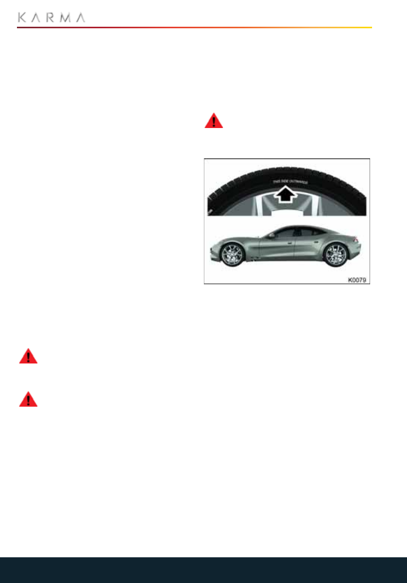
134
TIRE CARE
4. If the tire pressure is too high, remove
the gauge and allow air out of the tire
by pressing the center of the valve.
Reattach the gauge to the valve and
check the pressure.
5. Repeat the process adding or removing
air as required until the correct tire
pressure is reached.
6. Reinstall the valve cap.
Note: It is an offense in certain countries to
drive a vehicle with incorrect tire pressures.
TIRE VALVES
Keep the valve caps screwed down firmly
to prevent water or dirt entering the valve.
Check the valves for leaks when checking
the tire pressures.
FLAT SPOTS
If the vehicle is stationary for a long period,
when the ambient temperature is high, the
tires may form flat spots. When the vehicle
is driven, these flat spots will cause a
vibration which will steadily disappear as
the tires warm up and regain their original
shape.
REPLACEMENT WHEELS AND
TIRES
WARNING: For your safety, it is
recommended that only wheels and
tires that match the original specification
are used on the vehicle.
WARNING: Operation of the TPMS
may be affected if the tires are
replaced with a different specification to
the originals.
Wheel rims and tires are matched to suit
the handling characteristics of the vehicle.
Always check that replacement tires
comply with the original specification. If
tires other than those specified are used,
ensure that the load and speed ratings
(shown on the tire side wall) equal or
exceed those of the original specification.
For the specification of the original wheels
and tires installed on the Karma, refer to
“Tire Specifications” on page 152.
Ideally, tires should be replaced as sets of
four. If this is not possible, replace the tires
in pairs (front and rear). When tires are
replaced, the wheels should always be re-
balanced and the alignment checked.
ASYMMETRIC TIRES
WARNING: Vehicle control and
handling will be seriously impaired if
the tires are incorrectly installed on the
wheels.
Your Revero is equipped with asymmetric
tires which must be mounted on the wheel
with the correct sidewall facing outwards
from the vehicle. In this case, the sidewall of
the tire is marked with the words THIS SIDE
OUTWARDS.
When new tires have been installed,
always make sure that the tires are
correctly orientated to the wheel.

135
TIRE CARE
DRIVING IN LOW AMBIENT
TEMPERATURES
The tires installed on your Karma are
specially formulated summer tires that are
not intended to be driven in near-freezing
temperatures, through snow or on ice.
Tire performance reduces in low ambient
temperatures, resulting in less grip and an
increased susceptibility to damage from
impacts. When driving in sustained
temperatures below 50°F (10°C), it is
recommended that winter tires be
installed.
WINTER TIRES AND TIRE CHAINS
WINTER TIRES
WARNING: Always adhere to the tire
manufacturer’s instructions, paying
particular attention to the maximum speed
at which the vehicle can be driven and the
correct tire pressures.
CAUTION: Winter tires should not be
installed on the standard production
wheels installed on your Revero. The
installation of winter tires may cause
interference issues with chassis and body
components.
Karma Automotive has designed a winter
wheel and tire combination specifically for
your Revero. Please contact your local
Karma Service Provider for information on
how to purchase these wheels and tires.
Generally, winter tires have lower speed
ratings than factory equipped tires and
may not match the potential maximum
vehicle speed. Never exceed the maximum
speed rating of the tire.
If you install winter tires, they must be the
same size, brand, construction and tread
pattern for an axle pair (front and rear).
TIRE CHAINS
WARNING: Tire chains must only be
used in conjunction with the Karma
approved winter wheels and tires.
CAUTION: To avoid possible damage
to the vehicle, use only very low
profile tire cables instead of chains. The
largest style of tire chain that should be
used on the Revero is the Society of
Automotive Engineers (SAE) class "S."
Note: Only install snow cables on the driven
axle (rear wheels).
Use of tire chains may be prohibited
according to location. Check the local laws
before installing tire chains.
Note: Only the 21” tire packages have
clearance for tire chains. The 22” tire
packages do not have enough clearance
for chains.
When installing tire chains, make sure they
are the proper size for the tires on your
Revero and are installed according to the
chain manufacturer’s suggestions.
When using tire chains:
•Drive at a reduced speed.
•Avoid fully loading your vehicle as this
will reduce the clearance between the
body and the wheels.
•Avoid tire/vehicle damage by removing
the tire chains as soon as the conditions
allow.
Contact your local Karma Service Provider
for a list of approved tire chains and
manufacturers.

136
TIRE PRESSURE MONITORING SYSTEM (TPMS)
Tire Pressure Monitoring Sys tem (TPMS)
TIRE PRESSURE MONITORING
SYSTEM (TPMS)
Your vehicle will not have a spare tire and
will not use run-flat tires. The driver is solely
responsible to periodically check the tire
pressures. In case the user installs run-flat
tires on the vehicle, it falls under his/her
responsibility to make sure that the tires
are inflated to the correct pressure level to
prevent a TPMS malfunction.
Your vehicle has also been equipped with a
TPMS malfunction indicator to indicate
when the system is not operating properly.
The TPMS malfunction indicator is provided
by a separate telltale, which displays the
symbol “TPMS” when illuminated.
When the malfunction indicator is
illuminated, the system may not be able to
detect or signal low tire pressure as
intended. TPMS malfunctions may occur
for a variety of reasons, including the
installation of replacement or alternate
tires or wheels on the vehicle that prevent
the TPMS from functioning properly.
Always check the TPMS malfunction telltale
after replacing one or more tires or wheels
on your vehicle to ensure that the
replacement or alternate tires and wheels
allow the TPMS to continue to function
properly.
The TPMS is standard equipment in all
Karma vehicles. The following conditions
may trigger the warning light to turn on:
•Low pressure soft (80% of
recommended cold tire pressure)
•Low pressure hard (23.2 PSI)
•Fast pressure loss
•Low battery charge
The telltale icon will flash for 1 min
if there is a system malfunction,
then become stable until the malfunction is
corrected.
The CIU will display each sensor, showing
its corresponding wheel temperature and
pressure values.
TIRE PRESSURE CORRECTION
The tire pressure indicator light does not
automatically turn off when the tire
pressure is adjusted for all four tires. If the
condition that is causing the TPMS icon to
be illuminated is corrected, the vehicle
must be powered-down normally, then re-
energized and placed in System Ready
mode. If the TPMS module registers all
criteria as normal, the icon will go out.
If a TPMS sensor detects a problem and
the corrective action requires a repair or
tire replacement, the tire position can be
relearned manually.
With the vehicle in Park [P] and in System
Ready mode, you can enable the tire
learning feature in the CIU by selecting:
•Settings > Diagnostics> TPMS > Manual
Re-learn
Once learning is enabled, change the
pressure (either add air, or let some out) on
the corresponding tire. The system will
acknowledge the change in pressure with a
single short chirp. You must follow this
sequence:
•Front Left (FL), Front Right (FR), Rear
Right (RR), and Rear Left (RL)
Before moving to the next wheel, wait for
the system to issue a double chirp,
signaling each wheel has been identified
and the pressure value has been updated.
The corresponding turn indicator will flash
also. If for some reason the TPMS sensor
could not be communicated, or it times out,
a longer chime will sound, which means the

137
TIRE PRESSURE MONITORING SYSTEM (TPMS)
system could not learn the corresponding
wheel.
You will hear a double-chirp when all four
wheels have successfully relearned.
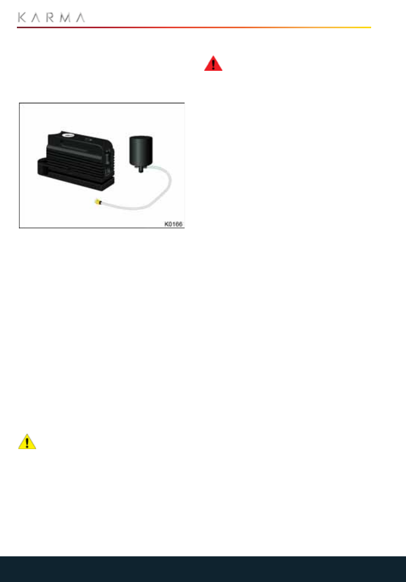
138
TIRE REPAIR KIT
Tire Repair Kit
TIRE REPAIR KIT
Your Revero has no spare tire. Instead, you
have been provided with a tire repair kit
located in the storage space beneath the
trunk floor.
The tire repair kit consists of a canister of
tire sealant and a compressor.
Note: The canister only contains enough
sealant to seal one tire.
The tire sealant contains liquid latex and a
propellant. When injected into the tire
through the valve, the liquid latex
penetrates the puncture site and cures to
form a temporary repair.
Note: The kit can only be used to repair
small punctures in the tire tread. In the
event of punctures larger than 1/4 inch
(6 mm), severe tread damage, a damaged
sidewall, ripped tires or tires that have
come off the rim, please contact your
Roadside Assistance provider.
You are advised to have the tire repaired or
replaced as soon as possible.
CAUTION: Do not drive on a deflated
tire as this can cause serious damage
to the wheel and the vehicle. If the tire is too
badly damaged, call Roadside Assistance
to have the vehicle transported to a repair
facility.
TIRE SEALANT
WARNING: Always read and follow
the safety and handling instructions
on the label adhered to the sealant
canister.
The tire sealant supplied as part of the tire
repair kit has an expiration date printed on
the outside of the canister. Always replace
an expired tire sealant canister. If the tire
sealant has passed its expiration date, it
may not work as expected when you need
to use it in an emergency.
The tire sealant should always be replaced
with one of the same type and capacity.
This tire sealant has been approved for use
with your Revero and will not damage the
TPMS sensors.
Tire sealant canisters are available from all
Karma Service Providers.
Note: The sealant/air hose assembly will
need to be replaced after each use. See
“Replacing the Canister/Air Hose
Assembly” on page 141.
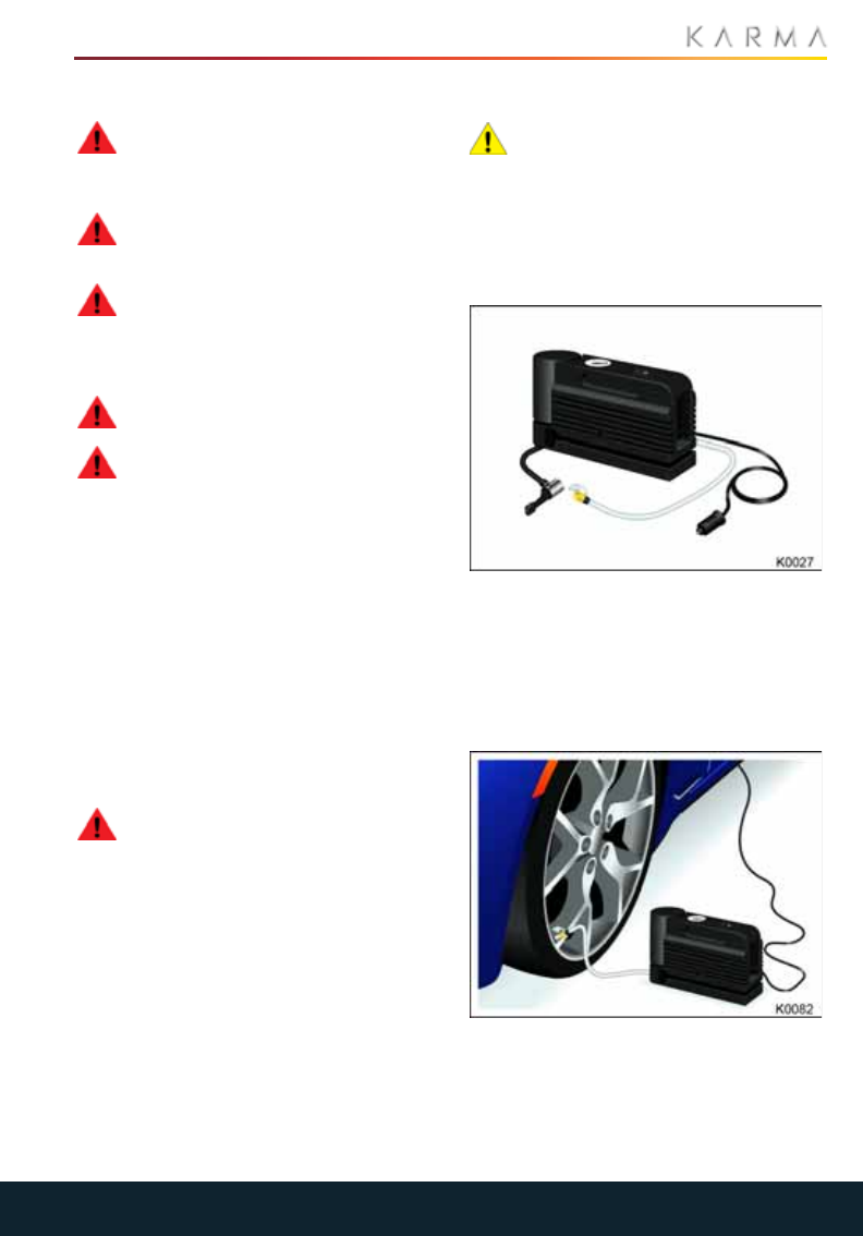
139
TIRE REPAIR KIT
SAFETY PRECAUTIONS
WARNING: Under no circumstances
should speeds of 55 mph (90 km/h)
be exceeded while driving with a repaired
tIre.
WARNING: Never drive with a
deflated tire, vehicle handling and
braking will be compromised.
WARNING: Always read the
directions and warnings on the tire
sealant before starting a repair. Follow the
directions on the canister exactly and pay
attention to the following precautions.
WARNING: Always keep the tire
sealant out of the reach of children.
WARNING: The tire sealant contains
components which are harmful if
consumed or inhaled:
•If swallowed, do not induce vomiting.
Seek medical assistance immediately.
•If inhaled, breathe fresh air. If breathing
is affected, seek medical assistance
immediately.
•If the sealant comes into contact with
the eyes, immediately flush the eyes
with water. If irritation persists, seek
medical assistance.
•Do not breathe gas, fumes, vapor or
spray that may be emitted from the tire
sealant. Inhalation can cause
drowsiness and dizziness.
WARNING: Store the tire sealant in
its correct location in the trunk.
Temperatures in other locations may
exceed safe storage conditions.
USING THE TIRE REPAIR KIT
CAUTION: If possible, stop in a safe
place away from traffic. Always ask
passengers to wait in a safe area away
from traffic. Switch on the hazard warning
flashers to alert other road users, then
follow these steps.
1. If possible, position the wheel with
puncture at the bottom.
2. Release the clear plastic hose from
around the base of the tire compressor
taking care to ensure the sealant
canister remains in place.
3. Detach the 12V power supply connector
and plug into one of the vehicle’s
accessory power supply sockets.
4. Thread the end of the hose onto the tire
valve.
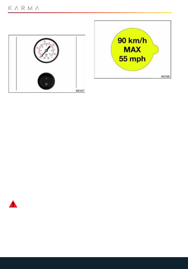
140
TIRE REPAIR KIT
5. Ensure the compressor is standing
upright with the pressure gauge facing
up.
6. Turn on the compressor to inject
sealant and air into the tire.
Note: The pressure gauge will initially
show a high pressure while the
compressor pushes the sealant into the
tire. Once the sealant is completely
dispersed into the tire, the pressure will
quickly drop and start to rise again as
the tire inflates with air only.
7. Monitor the tire pressure gauge and
inflate the tire to the recommended tire
pressure.
8. Tur n of f th e co mpre s so r a nd rem ove
the hose from the tire valve.
9. Wipe of any excess sealant from the tire
valve and wheel rim.
10. If the wheel rim has lifted from the
ground, drive immediately for 5 miles
(8 km) to distribute the sealant around
the tire. Do not exceed 25 mph
(40 km/h).
WARNING: If the required pressure
cannot be reached after
approximately 25 minutes, or the wheel rim
has not risen from the ground, then the tire
is too severely damaged for a safe repair.
Call Roadside Assistance to have the
vehicle transported. Do not drive!
11. Check the tire pressure once again and
inflate as required, using the black hose
located in the bottom of the
compressor.
12. Apply the warning label supplied with
the tire repair kit to a prominent area in
the vehicle to remind you not to exceed
55 mph (90 km/h) until the tire has
been professionally repaired or
replaced.
13. Dispose of the used sealant canister
and sealant/air hose assembly at a
local Karma Service Provider.
14. Replace the tire sealant canister and
sealant/air hose assembly. See
“Replacing the Canister/Air Hose
Assembly” on page 141.
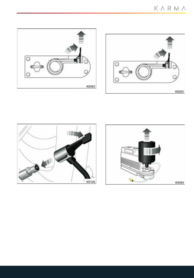
141
TIRE REPAIR KIT
USING THE COMPRESSOR
1. Release the black air only hose from the
sealant canister on the base of the tire
compressor.
2. Detach the 12V power supply connector
and plug into one of the vehicle’s
accessory power supply sockets.
3. Attach the air only hose to the tire valve
and press the lever down to secure it in
place.
4. Ensure the compressor is standing
upright with the pressure gauge facing
up.
5. Turn on the compressor to inflate the
tire.
REPLACING THE CANISTER/AIR
HOSE ASSEMBLY
1. Release the black air only hose from the
sealant canister on the base of the tire
compressor.
2. Unwrap the clear sealant/air hose from
the compressor.
3. Rotate the sealant canister so the clear
sealant/air hose is aligned with the slot
in the compressor.
4. Lift the canister/air hose assembly from
the compressor.
Note: Installation of the new canister is the
reverse of the removal process.
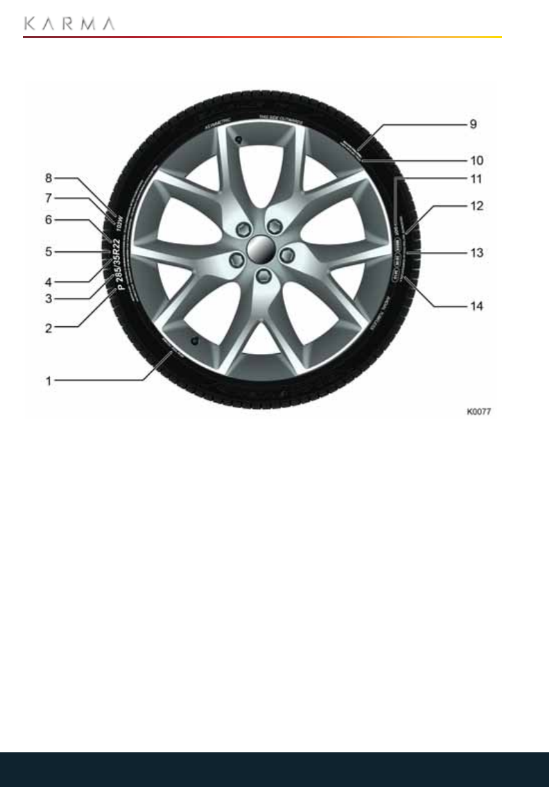
142
TIRE INFORMATION
Tire Information
TIRE MARKINGS
1. Tire composition and materials
2. Tire category
3. Tire width
4. Aspect ratio
5. Tire construction
6. Wheel diameter
7. Load index
8. Speed rating
9. Maximum permissible inflation pressure
10. Maximum tire load
11. U.S DOT Tire Identification Number
(TIN)
12. Treadwear grade
13. Traction grade
14. Temperature grade
Federal law requires tire manufacturers to
place standardized information on the
sidewall of all tires. This information
identifies and describes the fundamental
characteristics of the tire and also provides
the tire identification number for safety
standard certification and in case of a
recall.
TIRE CATEGORY
P indicates that the tire is for passenger
vehicles
TIRE WIDTH
This three digit number gives the width in
millimeters of the tire from sidewall edge to
sidewall edge.

143
TIRE INFORMATION
ASPECT RATIO
This two digit number, known as the aspect
ratio or profile, gives the sidewall height as
a percentage of the tread width. So, if the
tread width is 205 mm, and the aspect
ratio is 50, the sidewall height will be 102
mm.
TIRE CONSTRUCTION
R indicates that the tire is of Radial ply
construction.
WHEEL DIAMETER
This two digit number is the diameter of the
wheel rim in inches.
LOAD INDEX
This two or three digit number is the tire's
load index. It is a measurement of how
much weight each tire can support. This
number is not always shown.
SPEED RATING
The speed rating, when stated, denotes the
maximum speed at which the tire should be
used for extended periods. The ratings
range from 99 mph to 186 mph. These
ratings are listed in the following table.
U.S DOT TIRE IDENTIFICATION
NUMBER
This begins with the letters Department of
Transportation (DOT) and indicates that
the tire meets all federal standards. The
next two numbers or letters are the plant
code where it was manufactured, and the
last four numbers represent the week and
year the tire was built. For example, the
numbers 1716 means the 17th week of
2016. The other numbers are marketing
codes used at the manufacturer's
discretion. This information can be used to
contact consumers if a tire defect requires
a recall.
MAXIMUM PERMISSIBLE INFLATION
PRESSURE
The maximum inflation pressure for the
tire. This pressure should not be used for
normal driving.
TREADWEAR GRADE
This number indicates the tire's wear rate.
The higher the treadwear number is, the
longer it should take for the tread to wear
down. A tire rated at 400 for example, will
last twice as long as a tire rated at 200.
TRACTION GRADE
This letter indicates a tire's ability to stop
on wet pavement. A higher graded tire
should allow you to stop your Revero on
wet roads in a shorter distance than a tire
with a lower grade.
Tract io n is g rade d from highest to lowest
as AA, A, B, and C.
TEMPERATURE GRADE
Heat resistance grading. The tires
resistance to heat is grade A, B, or C, with A
indicating the greatest resistance to heat.
This grading is provided for a correctly
inflated tire, which is being used within its
speed and loading limits.
TIRE COMPOSITION AND MATERIALS
The number of plies in both the tread area,
and the sidewall area, indicates how many
layers of rubber coated material make up
the structure of the tire. Information is also
provided on the type of materials used.
Rating Speed mph (km/h)
Q 99 (160)
R106 (170)
S 112 (180)
T 118 (190)
U124 (200)
H 130 (210)
V 149 (240)
W168 (270)
Y186 (300)

144
TIRE INFORMATION
MAXIMUM TIRE LOAD
The maximum load which can be carried by
the tire.
UNIFORM TIRE QUALITY
GRADING
UNITED STATES DEPARTMENT OF
TRANSPORTATION/UNIFORM TIRE
QUALITY GRADE
The following information relates to the tire
grading system developed by the National
Highway Traffic Safety Administration
(NHTSA) which will grade tires by tread
wear, traction and temperature
performance.
Note: Tires that have deep tread, and
winter tires, are exempt from these
marking requirements.
Quality grades, where applicable, can be
found on the tire sidewall between the
tread shoulder and maximum section
width.
For example:
In addition to the marking requirements,
passenger car tires must conform to
Federal Safety Requirements.
TREADWEAR
The treadwear grade is a comparative
rating based on the wear rate of the tire
when tested under controlled conditions on
a specified government test course.
For example; a tire graded 150 would wear
one and a half (1.5) times as well on a
government test course as a tire graded
100. The relative performance of tires
depends on the actual conditions of their
use, however, and may depart significantly
from the norm due to variations in driving
habits, service practices, and differences in
road characteristics and climate.
TRACTION
WARNING: The traction grade
assigned to this tire is based on
straight-ahead braking traction tests, and
does not include; acceleration, cornering,
hydroplaning or peak traction
characteristics.
The traction grades, from highest to lowest,
are; AA, A, B, and C. These grades
represent a tire’s ability to stop on a wet
pavement as measured under controlled
conditions on specified government test
surfaces of asphalt and concrete. A tire
marked C may have poor traction
performance.
TEMPERATURE
WARNING: The temperature grade
for this tire is established for a tire
that is properly inflated and not
overloaded. Excessive speed, under-
inflation, or excessive loading, either
separately or in combination, can cause
heat buildup and possible tire failure.
The temperature grades are A (the
highest), B, and C, representing the tire's
resistance to the generation of heat and its
ability to dissipate heat when tested under
controlled conditions on a specified indoor
laboratory test wheel.
Sustained high temperature can cause the
material of the tire to degenerate and
reduce tire life, and excessive temperature
can lead to sudden tire failure.
The grade C corresponds to a level of
performance which all passenger car tires
must meet under the Federal Motor Safety
Standard (FMVSS) No. 109.
Grades B and A represent higher levels of
performance on the laboratory test wheel
than the minimum required by law.
Treadwear Traction Temperature
200 AA A
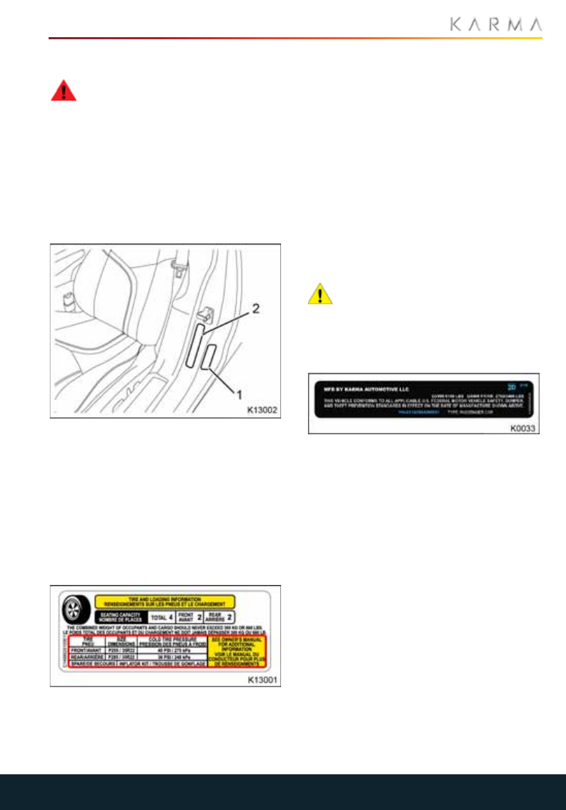
145
TIRE INFORMATION
LOADING THE VEHICLE
WARNING: Overloading the vehicle
will have an adverse effect on
braking and handling characteristics, which
could compromise your safety or damage
the vehicle.
It is important to understand how much
weight your Revero can safely carry. This
weight is called the vehicle capacity weight
and includes the weight of all occupants,
cargo and any additional equipment fitted
to the vehicle since it was manufactured.
There are two labels affixed to your Revero
that state how much weight your vehicle
can safely carry:
1. Tire and loading information label.
2. Vehicle certification label.
With the driver’s door open, these labels
are located on the center door post.
TIRE AND LOADING INFORMATION
LABEL / VEHICLE PLACARD
The tire and loading information label
contains the following information:
•The maximum number of occupant
seating positions.
•The maximum vehicle capacity weight in
kilograms (kg) and pounds (lbs).
•The size of the tires originally installed
on the vehicle.
•The cold inflation pressures for the
original specification of front and rear
tires.
The stated tire pressures provide optimum
ride and handling characteristics for all
normal operating conditions.
Note: This label must not be changed, even
if different wheels are installed at a later
stage.
VEHICLE CERTIFICATION LABEL
CAUTION: To prevent serious
damage to the vehicle, never load the
vehicle so that it is heavier than the GVWR
or exceed the individual GAWR weights.
Heavy loads should be evenly distributed
throughout the vehicle.
The vehicle certification label contains the
following information:
•GVWR - Gross Vehicle Weight Rating.
The GVWR is the maximum allowable
total mass of the vehicle. This is
calculated as the weight of the vehicle,
all passengers, fuel and cargo.
•GAWR FR and GAWR RR - Gross Axle
Weight Rating for the front and rear
axles.
The GAWR is the maximum distributed
weight that may be supported by an
axle on the vehicle.
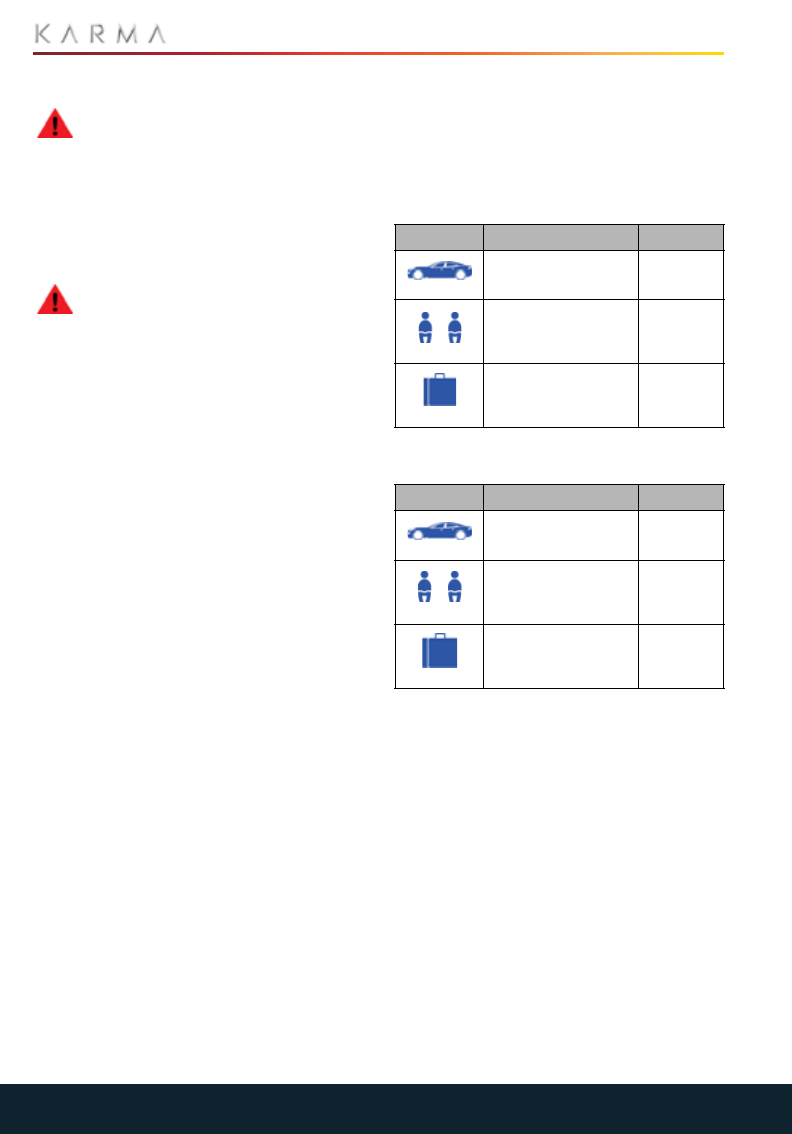
146
TIRE INFORMATION
CARRYING ITEMS
WARNING: The trunk is the preferred
place to carry objects. In an accident,
during hard braking, or sudden maneuvers,
loose items carried in the vehicle’s cabin
area can be thrown around, and cause
injury to occupants unless securely
fastened.
TOWING A TRAILER
WARNING: Do not tow a trailer with
your Revero. The Karma has not
been designed to have a trailer hitch
installed on it. The installation of a trailer
hitch may cause serious damage to the
vehicle which could result in an accident or
serious injury.
STEPS FOR DETERMINING
CORRECT LOAD LIMIT
1. Locate the statement “The combined
weight of occupants and cargo should
never exceed XXX kg or XXX lbs” on your
vehicle’s placard (Tire information and
loading label).
2. Determine the combined weight of the
driver and passengers that will be riding
in your vehicle.
3. Subtract the combined weight of the
driver and passengers from XXX kg or
XXX lbs.
4. The resulting figure equals the available
amount of cargo and luggage load
capacity. For example, if the “XXX”
amount equals 1400 lbs, and there will
be five 150 lb passengers in the vehicle,
the amount of available cargo and
luggage capacity is 650 lbs. (1400-750
(5x150) = 650 lbs)
5. Determine the combined weight of
luggage and cargo being loaded on the
vehicle. That weight may not safely
exceed the available cargo and luggage
load capacity calculated in Step 4.
EXAMPLE LOAD LIMIT CALCULATIONS
The number and weight of passengers will
affect the cargo and luggage load
capacity. The following are typical
examples of calculated load limits.
Example 1:
Example 2:
Note: If the passengers weigh more, the
available cargo capacity will decrease.
Item Description Total
Vehicle Capacity
Weight = 700 lbs
Subtract
Occupant Weight
(2 x 150 lbs) =
300 lbs
Available Cargo
or Occupant
Weight =
450 lbs
Item Description Total
Vehicle Capacity
Weight = 700 lbs
Subtract
Occupant Weight
(4 x 150 lbs) =
600 lbs
Available Cargo
or Occupant
Weight =
150 lbs

147
GLOSSARY OF TERMS
Glossary of Terms
WHEELS AND TIRES GLOSSARY
ACCESSORY WEIGHT
The combined weight (in excess of those
items replaced) of items available as
factory installed equipment.
BEAD
The inner edge of a tire that is shaped to fit
to the rim and form an air tight seal. The
bead is constructed of steel wires which
are wrapped, or reinforced, by the ply
cords.
COLD TIRE PRESSURE
The air pressure in a tire which has been
standing in excess of three hours, or driven
for less than one mile.
CURB WEIGHT
The weight of a standard vehicle, including
a full tank of fuel, any optional equipment
installed, and with the correct fluid levels.
GROSS VEHICLE WEIGHT
The maximum permissible weight of a
vehicle with driver, passengers, load,
luggage, and equipment.
KPA (KILO PASCAL)
A metric unit used to measure pressure.
One kilo Pascal equals approximately 0.145
psi.
MAXIMUM INFLATION PRESSURE
The maximum pressure to which the tire
should be inflated. This pressure is given on
the tire side wall in psi (lbf/in2) and kPa.
Note: This pressure is the maximum
allowed by the tire manufacturer. It is not
the pressure recommended for use.
MAXIMUM LOADED VEHICLE WEIGHT
The sum of curb weight, accessory weight,
vehicle capacity weight, and production
options weight.
PRODUCTION OPTIONS WEIGHT
The combined weight of options installed
which weigh in excess of 3 lbs (1.4 kg) more
than the standard items that they
replaced, and are not already considered
in curb or accessory weights.
PSI (LBF/IN2)
Pounds per square inch, an imperial unit of
measure for pressure.
RIM
The metal support for a tire, or tire and
tube, upon which the tire beads are seated.
VEHICLE CAPACITY WEIGHT
The number of seats multiplied by 150 lbs
(68 kg) plus the rated amount of
load/luggage.
This Page Intentionally Left Blank

149
TECHNICAL SPECIFICATIONS
Technical Sp ecificati ons
VEHICLE AND COMPONENT IDENTIFICATION
Vehicle Identification Number (VIN).............................................................................................150
VEHICLE DIMENSIONS AND WEIGHTS
Dimensions.............................................................................................................................................151
Vehicle Weights....................................................................................................................................151
WHEELS AND TIRES
Wheel Specifications.........................................................................................................................152
Tire Specifications..............................................................................................................................152
SUBSYSTEM SPECIFICATIONS
Engine.....................................................................................................................................................153
Traction Motors....................................................................................................................................153
Propulsion Unit/Differential............................................................................................................153
Steering.................................................................................................................................................. 154
Front Suspension................................................................................................................................154
Rear Suspension.................................................................................................................................154
Brakes.....................................................................................................................................................155
Battery - 12V........................................................................................................................................155
Battery - High Voltage......................................................................................................................155
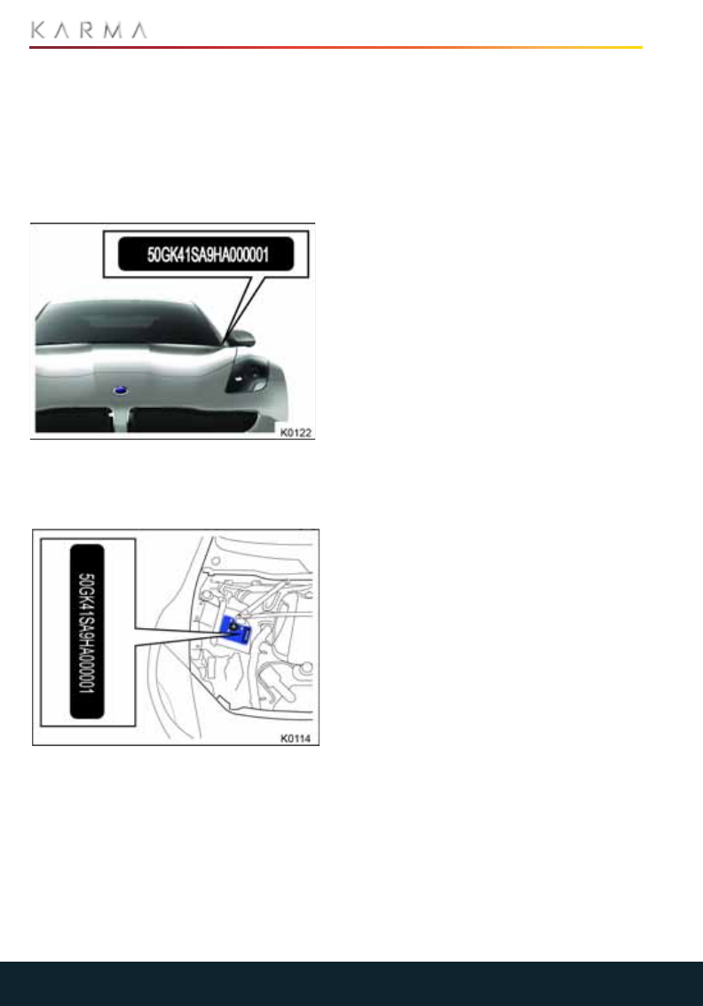
150
VEHICLE AND COMPONENT IDENTIFICATION
Vehicle and Component Identific ation
VEHICLE IDENTIFICATION
NUMBER (VIN)
If you need to communicate with Karma
Automotive, you may be asked to provide
the Vehicle Identification Number (VIN).
You can find the VIN in the following
locations:
•Top of dashboard - the VIN is stamped
on a plate which is visible through the
lowest part of the left-hand side of the
windshield.
•Chassis - the VIN is stamped on the
vehicle chassis, and is visible on the
right-hand front suspension mounting
in the engine compartment.
Note: The VIN is also displayed on the
vehicle certification label. See “Vehicle
certification label” on page 145.
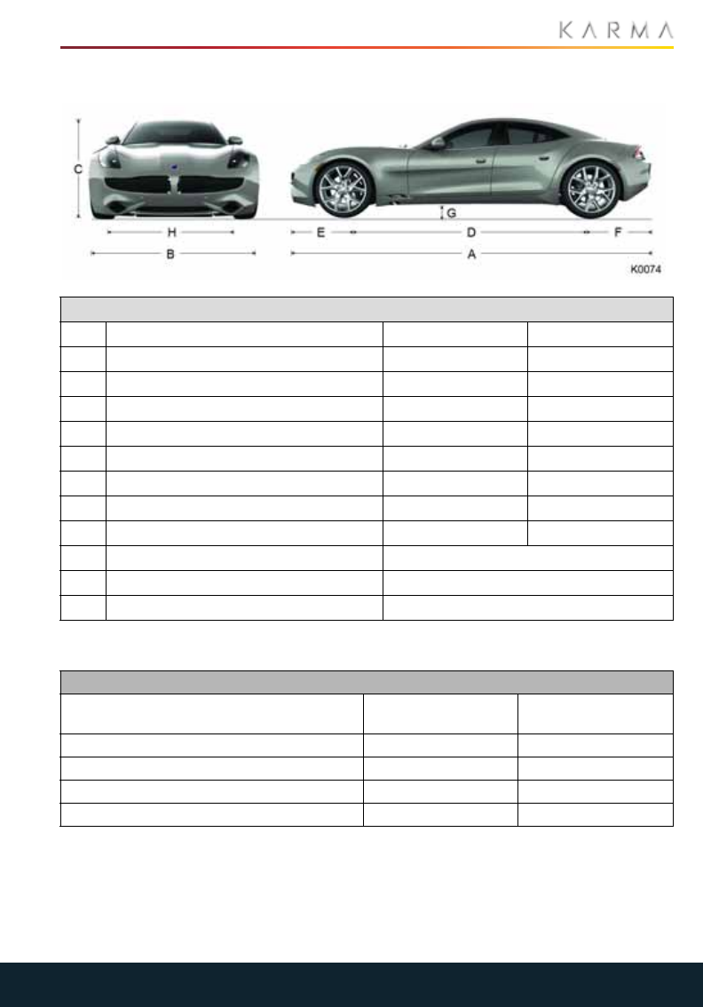
151
VEHICLE DIMENSIONS AND WEIGHTS
Vehicle Dimens ions and Weights
DIMENSIONS
VEHICLE WEIGHTS
Dimensions
A Overall length 196.8 in 4998 mm
B Overall width (including mirrors) 84.0 in 2133 mm
C Overall height 52.4 in 1330 mm
D Wheel base 124.4 in 3160 mm
E Front overhang 35.9 in 913 mm
F Rear overhang 36.4 in 925 mm
G Ground clearance 5.3 in 135 mm
H Track - Front 66.6 in 1692 mm
Track - Rear 67.0 in 1701 mm
Approach angle 11.4°
Departure angle 20.0°
Breakover angle 9.9°
Weights
Curb weight (full fuel tank, correct fluid
levels, no occupants or cargo)
5400 lb 2450 kg
Gross Vehicle Weight Rating 6100 lb 2767 kg
Gross Axle Weight Rating - Front 2750 lb 1248 kg
Gross Axle Weight Rating - Rear 3400 lb 1543 kg
Payload Weight 700 lb 318 kg

152
WHEELS AND TIRES
Wheels and Tires
WHEEL SPECIFICATIONS
TIRE SPECIFICATIONS
Wheel type Location Size
Dune Twist - Two Tone Front 22 x 8.5J
Rear 22 x 9.5J
Dune Twist - Midnight Chrome Front 22 x 8.5J
Rear 22 x 9.5J
Forged Multi-spoke Front 22 x 8.5J
Rear 22 x 9.5J
Carbon Front 22 x 8.5J
Rear 22 x 9.5J
Diamond Facet Front 21 x 8.5J
Rear 21 x 9.0J
Road wheel nut torque 220 Nm 162 lbf.ft
Note: For details on where to lift the vehicle, see “Raising the Vehicle” on page 123.
Tire type Location Size Pressures
Standard production tires (North American market only)
Goodyear Eagle F1 Supercar Front 255/35 R22 99W inflate to 40 psi
Rear 285/35 R22 102W inflate to 36 psi
Optional summer tires
Pirelli P Zero Front 245/40 R21 inflate to 35 psi
Rear 265/40 R21 inflate to 38 psi
Optional winter tires (North American market only)
Pirelli Scorpion Front 255/40 R21 inflate to 35 psi
Rear 265/40 R21 inflate to 38 psi

153
SUBSYSTEM SPECIFICATIONS
Subsystem Specifications
ENGINE
TRACTION MOTORS
PROPULSION UNIT/DIFFERENTIAL
Engine
Type
GM L4 Ecotec engine.
DOHC with variable valve timing.
Turbocharged.
Displacement 122 ci (1998 cc)
Number of cylinders 4 in line
Firing order 1-3-4-2
Bore 3.39 in (86 mm)
Stroke 3.39 in (86 mm)
Compression ratio 9.25:1
Fuel system Direct injection
Spark plug type AC Delco IRIDIUM 41-108
Spark plug gap 0.032-0.035 in (0.81-0.90 mm)
Fuel
UNLEADED fuel. Refer to the label on the
inside of the fuel filler cover for the Octane
rating recommended for your Revero.
Traction motors
Type 2 x high voltage motors.
Aluminum casings. Water cooled.
Rating 345 Volts
Maximum speed 6000 rpm
Propulsion unit / Differential
Type Water cooled, single speed.
Reverse mode Reverse direction of motors, limited to 30 mph
(48 km/h)
Final drive ratio 4.1:1

154
SUBSYSTEM SPECIFICATIONS
STEERING
FRONT SUSPENSION
REAR SUSPENSION
Steering
Type Rack and pinion with electro hydraulic power
steering system and variable sensitivity.
Number of turns lock to lock 2.8
Turning circle (curb to curb) 12.45 m (40 ft 10 in)
Front suspension
Type Independent. Co-axial coil spring/telescopic
damper. Sway bar.
Alignment optimum 0.1°
tolerance ± 0.06°
Camber
optimum -0.5° per side
0.0° side to side
tolerance ± 0.2° per side
± 0.3° side to side
Caster
optimum 6.0° per side
0.0 side to side
tolerance ± 0.3° per side
± 0.4° side to side
Rear suspension
Type Independent. Co-axial coil spring/telescopic
damper. Sway bar.
Alignment
optimum 0.05° per side
0.1° side to side
tolerance ± 0.03° per side
± 0.06° side to side
Camber
optimum -1.25° per side
0.0° side to side
tolerance ± 0.2° per side
± 0.3° side to side
Thrust optimum 0.0°
tolerance ± 0.2°

155
SUBSYSTEM SPECIFICATIONS
BRAKES
BATTERY - 12V
BATTERY - HIGH VOLTAGE
Brakes
Type
Electro hydraulic brake boost unit with
integrated chassis control function.
Anti-lock Braking System (ABS).
Advanced regenerative blended brake
system.
Calipers Front: Six piston monoblock
Rear: Four piston
Rotors
Ventilated front and rear rotors.
Front: 370 mm diameter
Rear: 365 mm diameter
Parking brake Electrically actuated cable operation of
parking brake.
Brake pedal free travel Not adjustable
Battery - 12V
Type Exide
Maintenance free, sealed for life.
Rating 70 Amp/hr.
Cold Cranking Amps (CCA): 720.
Voltage and polarity 12V. Negative (-) ground
Battery - high voltage
Type Lithium ion (Li-ion) with Nanophosphate™
technology
Weight 606 lb. (275 kg)
Rating 20 kWh (Peak)
Voltage and polarity 345V DC. Negative (-) ground
This Page Intentionally Left Blank

Index-1
Index
About Seat Belts.................................................................................................................................................30
About the Key FOB .............................................................................................................................................16
Accessory mode.................................................................................................................................................. 73
Accessory Power Outlets ................................................................................................................................90
Accessory Sockets..............................................................................................................................................90
Accessory weight ...............................................................................................................................................147
Activating valet mode ......................................................................................................................................23
Adding engine oil ...............................................................................................................................................107
Additional Procedures Required at Specific Intervals.......................................................................127
Adjusting the height of the front shoulder belt.......................................................................................31
Advanced Driver Assistance System (ADAS)........................................................................................84
Age degradation................................................................................................................................................ 131
Air bag module covers..................................................................................................................................... 116
Air Bag Service Information ..........................................................................................................................42
Air Bag Warning Labels ................................................................................................................................... 41
Air conditioning....................................................................................................................................................69
Air distribution ..................................................................................................................................................... 70
Air recirculation ................................................................................................................................................... 70
Alternative Fuels.................................................................................................................................................99
Answering calls....................................................................................................................................................64
Anti-Lock Braking System (ABS)................................................................................................................. 78
Applying the parking brake............................................................................................................................ 79
Approach lighting ................................................................................................................................................ 51
Approved Fluids and Capacities................................................................................................................. 112
Aspect ratio......................................................................................................................................................... 143
Assessing tire wear.......................................................................................................................................... 132
Asymmetric tires............................................................................................................................................... 134
Attaching the Vehicle Recovery Eye ........................................................................................................ 124
Audio........................................................................................................................................................................ 57
Audio........................................................................................................................................................................59
Auto climate control ..........................................................................................................................................68
Automatic car washers or pressure washer.......................................................................................... 114
Automatic Locking...............................................................................................................................................19
Automatic wiper..................................................................................................................................................50
Battery - 12V...................................................................................................................................................... 155
Battery - High Voltage ................................................................................................................................... 155
Battery coolant level ........................................................................................................................................ 110
Bead........................................................................................................................................................................147
Before storing the vehicle...............................................................................................................................117
Blower speed/temperature control............................................................................................................68
Bluetooth................................................................................................................................................................64
Body Repairs ........................................................................................................................................................... 7
Brake Fluid...........................................................................................................................................................108
Brakes.................................................................................................................................................................... 155
Brakes...................................................................................................................................................................... 78
Bringing the vehicle out of storage ............................................................................................................ 119
Cabin air filter........................................................................................................................................................ 71

Index-2
California Perchlorate Advisory...................................................................................................................... 8
California Proposition 65 .................................................................................................................................. 8
Call in progress ....................................................................................................................................................63
Canada.....................................................................................................................................................................10
Canceling cruise control...................................................................................................................................82
Caring for Seat Belts.........................................................................................................................................32
Caring for the Key FOB......................................................................................................................................18
Carpets...................................................................................................................................................................116
Carrying items....................................................................................................................................................146
Changing stations...............................................................................................................................................60
Changing the cruising speed..........................................................................................................................82
Charging Port.......................................................................................................................................................92
Charging System Components.....................................................................................................................92
Charging the Vehicle..........................................................................................................................................92
Charging the Vehicle..........................................................................................................................................94
Charging Time......................................................................................................................................................96
Checking the fluid level ...................................................................................................................................108
Checking the fluid level ...................................................................................................................................109
Checking the oil level........................................................................................................................................ 107
Checking the Wiper Blades............................................................................................................................ 113
Checking tire pressures..................................................................................................................................133
Child restraints for larger children..............................................................................................................34
Child restraints for small children and babies .......................................................................................34
Child Restraints....................................................................................................................................................34
Child Restraints ...................................................................................................................................................34
Child Safety Locks ...............................................................................................................................................19
Choosing a child restraint ...............................................................................................................................35
Chrome/metal surfaces..................................................................................................................................116
Cleaning and Vehicle Care ............................................................................................................................ 114
Cleaning the camera.........................................................................................................................................87
Cleaning the DIS and CIU Screens.............................................................................................................116
Cleaning the Exterior........................................................................................................................................ 114
Cleaning the Interior......................................................................................................................................... 115
Cleaning the sensors........................................................................................................................................ 86
Cleaning the Solar Roof.................................................................................................................................. 115
Cleaning the underside ................................................................................................................................... 114
Climate control.....................................................................................................................................................65
Climate Control................................................................................................................................................... 68
Closing the hood................................................................................................................................................105
Cold tire pressure ............................................................................................................................................. 147
Cold Weather Charging Considerations ..................................................................................................96
Consumer Information.......................................................................................................................................10
Coolant...................................................................................................................................................................110
Correct Seating Position..................................................................................................................................26
Creating a PIN for valet mode:.....................................................................................................................22
Cruise Control.......................................................................................................................................................82
Cruise Control.......................................................................................................................................................82
Curb weight......................................................................................................................................................... 147
Curtain air bags...................................................................................................................................................40

Index-3
Daily checks......................................................................................................................................................... 103
Data Recording ......................................................................................................................................................8
Daytime running lamps..................................................................................................................................... 51
DC Fast Charging ...............................................................................................................................................96
Defrosters.............................................................................................................................................................. 67
Deployment Effects...........................................................................................................................................40
Dimensions ........................................................................................................................................................... 151
Drive mode............................................................................................................................................................ 73
Driver Information System (DIS) Canadian Specification .................................................................46
Driver Information System (DIS) USA Specification ...........................................................................45
Driver’s Seat Memory.......................................................................................................................................28
Drivers Assistance..............................................................................................................................................84
Driving in Low Ambient Temperatures .................................................................................................... 135
Driving Modes ...................................................................................................................................................... 76
Dual zone temperature....................................................................................................................................69
Easy Entry and Exit............................................................................................................................................29
Electric drive components and the engine coolant levels................................................................ 110
Electric Seats........................................................................................................................................................ 27
Electric Vehicle Precautions.............................................................................................................................. 7
Electrical outlets..................................................................................................................................................93
Electronic Stability Control (ESC).................................................................................................................81
Electronic Stability Control..............................................................................................................................81
Emergency Access..............................................................................................................................................19
Emergency braking............................................................................................................................................ 79
Emergency Release Cable .............................................................................................................................96
Emergency shut down procedure................................................................................................................74
Emergency unlocking.........................................................................................................................................19
Emergency use....................................................................................................................................................80
Emission control................................................................................................................................................ 104
Engaging cruise control ...................................................................................................................................82
Engine Compartment Fuse Box ................................................................................................................. 120
Engine Compartment Overview.................................................................................................................106
Engine Compartment .....................................................................................................................................106
Engine Oil ..............................................................................................................................................................107
Engine.................................................................................................................................................................... 153
Entry Gate/Canadian Programming..........................................................................................................89
Entry.........................................................................................................................................................................29
Error messages...................................................................................................................................................80
Ethanol fuels.........................................................................................................................................................99
EV Charge Station..............................................................................................................................................96
Event data recording...........................................................................................................................................8
Example load limit calculations .................................................................................................................. 146
Exit ............................................................................................................................................................................29
Express window operation.............................................................................................................................53
Extension cords ...................................................................................................................................................93
Exterior Lighting ...................................................................................................................................................51
Exterior Lighting................................................................................................................................................... 51
Exterior Mirrors....................................................................................................................................................54
Exterior Overview................................................................................................................................................12

Index-4
Exterior Sound .....................................................................................................................................................83
Exterior Sound .....................................................................................................................................................83
Exterior.....................................................................................................................................................................12
Fan Speed..............................................................................................................................................................66
Fastening the seat belt .....................................................................................................................................31
Favorite access.................................................................................................................................................... 57
Favorites................................................................................................................................................................. 57
Filling up the brake reservoir........................................................................................................................108
Filling up the coolant reservoirs.................................................................................................................... 111
Filling up the power steering reservoir....................................................................................................109
Filling up the washer reservoir ...................................................................................................................... 111
Flat spots.............................................................................................................................................................. 134
Floor Mats..............................................................................................................................................................117
Fluid replacement.............................................................................................................................................103
Folding side mirrors ...........................................................................................................................................54
Forward Collision Warning (FCW) ..............................................................................................................85
Fresh air.................................................................................................................................................................. 70
From inside the vehicle......................................................................................................................................19
From outside the vehicle ..................................................................................................................................18
Front 12V power outlet ....................................................................................................................................90
Front seat heaters..............................................................................................................................................28
Front Suspension.............................................................................................................................................. 154
Fuel and Emission Systems Components..............................................................................................104
Fuel Filler ............................................................................................................................................................... 98
Fuel Filling ............................................................................................................................................................. 98
Fuel Specification............................................................................................................................................... 99
Fuel system .........................................................................................................................................................104
Fuel Tank Capacity ............................................................................................................................................ 99
Fuse Specifications ...........................................................................................................................................121
Fuses ......................................................................................................................................................................120
Garage Door Opener........................................................................................................................................ 88
General cleaning ................................................................................................................................................ 115
General Information ........................................................................................................................................103
General Information ..........................................................................................................................................78
General Information ..........................................................................................................................................92
Glass and mirrors ..............................................................................................................................................116
Glossary of Terms.............................................................................................................................................. 147
Glove Compartment and Valet Mode ........................................................................................................22
Glove Compartment..........................................................................................................................................22
Gross vehicle weight........................................................................................................................................ 147
Hand washing ..................................................................................................................................................... 114
Hazard Warning Flashers...............................................................................................................................52
Head lamp courtesy delay...............................................................................................................................51
Head lamp high beam .......................................................................................................................................51
Head lamp low beam.........................................................................................................................................51
Head lamp washers...........................................................................................................................................50
Heating.................................................................................................................................................................... 70
Homelink® Transmitter................................................................................................................................... 88
Hood.......................................................................................................................................................................105

Index-5
How the System Works ....................................................................................................................................39
If You Need Assistance .....................................................................................................................................10
Important Information .....................................................................................................................................39
Indicator Icons...................................................................................................................................................... 47
Information About Your Vehicle ..................................................................................................................... 7
Information and Assistance ...........................................................................................................................89
Inspection and Maintenance ....................................................................................................................... 130
Instruments...........................................................................................................................................................45
Integrated Headrests.......................................................................................................................................26
Interior Overview.................................................................................................................................................13
Interior Rear View Mirror ................................................................................................................................54
Interior......................................................................................................................................................................13
Intermittent wipe................................................................................................................................................50
Introduction..............................................................................................................................................................6
Jacking and Lifting the Vehicle................................................................................................................... 123
Key fob not detected..........................................................................................................................................74
Keyless start backup procedure ...................................................................................................................74
Keypad dialer .......................................................................................................................................................63
Knee air bags........................................................................................................................................................39
kPa (kilo Pascal)..................................................................................................................................................147
Lane departure sensitivity..............................................................................................................................85
Lane Departure Warning (LDW) .................................................................................................................84
Lane departure warning.................................................................................................................................84
Leather................................................................................................................................................................... 116
Load index ........................................................................................................................................................... 143
Loading the Vehicle.......................................................................................................................................... 145
Location of Air Bags ..........................................................................................................................................38
Locking and Unlocking the Vehicle................................................................................................................16
Maintenance and Repairs to Your Vehicle................................................................................................. 7
Maintenance Requirements......................................................................................................................... 103
Manual door opening........................................................................................................................................20
Master Lock and Unlock Switch.....................................................................................................................19
Maximum inflation pressure .........................................................................................................................147
Maximum loaded vehicle weight.................................................................................................................147
Maximum permissible inflation pressure................................................................................................ 143
Maximum tire load............................................................................................................................................ 144
Medical Safety...................................................................................................................................................... 17
Memory setting procedure.............................................................................................................................29
Methanol fuels .....................................................................................................................................................99
Minibar ....................................................................................................................................................................65
Mirrors .....................................................................................................................................................................54
Monthly checks .................................................................................................................................................. 103
My Karma...............................................................................................................................................................58
Navigation .............................................................................................................................................................58
Navigation ..............................................................................................................................................................61
Normal tire wear............................................................................................................................................... 132
Notes About This Manual ...................................................................................................................................6
Obstruction of Air Bags....................................................................................................................................40
Obtaining replacement keys and key fobs................................................................................................16

Index-6
Off.............................................................................................................................................................................. 70
Opening and Closing the Hood...................................................................................................................105
Opening the Doors ..............................................................................................................................................18
Opening the hood .............................................................................................................................................105
Opening the Trunk................................................................................................................................................21
Operating Notes.................................................................................................................................................. 72
Overview.................................................................................................................................................................56
Owner Maintenance........................................................................................................................................103
Paint Damage and Repair ............................................................................................................................. 115
Pairing a Phone ...................................................................................................................................................64
Park Distance Control (PDC)......................................................................................................................... 86
Parking Aids ......................................................................................................................................................... 86
Parking Brake .......................................................................................................................................................79
Passenger Air Bag Deactivation...................................................................................................................41
Phone.......................................................................................................................................................................58
Phone.......................................................................................................................................................................63
Plastic materials.................................................................................................................................................116
Poisonous fluids.................................................................................................................................................104
Polishing the Body............................................................................................................................................. 115
Power Steering Fluid .......................................................................................................................................109
Power Windows ..................................................................................................................................................53
Power Windows ..................................................................................................................................................53
Production options weight............................................................................................................................ 147
Programmable memory ..................................................................................................................................28
Programming a Device.................................................................................................................................... 88
Programming rolling code device equipment........................................................................................ 89
Propulsion Unit/Differential.........................................................................................................................153
PSI (lbf/in2) ......................................................................................................................................................... 147
Punctured tires ................................................................................................................................................... 131
Quality Control....................................................................................................................................................... 8
Raising the Vehicle...........................................................................................................................................123
Rear accessory power outlets ......................................................................................................................90
Rear fog lamps .....................................................................................................................................................51
Rear seat heaters...............................................................................................................................................28
Rear Suspension............................................................................................................................................... 154
Rear View Camera .............................................................................................................................................87
Rear window defroster ..................................................................................................................................... 71
Rear window inhibit............................................................................................................................................53
Rear window operation....................................................................................................................................53
Reformulated gasoline.................................................................................................................................... 99
REGEN mode.........................................................................................................................................................77
Regenerative Braking........................................................................................................................................79
Reinstallation........................................................................................................................................................117
Releasing the belt................................................................................................................................................31
Releasing the parking brake...........................................................................................................................79
Removing tar spots........................................................................................................................................... 114
Replacement Wheels and Tires .................................................................................................................134
Replacing a Fuse...............................................................................................................................................120
Replacing the Canister/Air Hose Assembly........................................................................................... 141

Index-7
Replacing the Key FOB Battery.....................................................................................................................18
Replacing the Wiper Blades.......................................................................................................................... 113
Reporting Safety Defects.................................................................................................................................10
Reprogramming a single button..................................................................................................................89
Restricted Performance.................................................................................................................................. 76
Resuming cruise control ..................................................................................................................................82
Rim...........................................................................................................................................................................147
Running Out of Fuel...........................................................................................................................................99
Safety features....................................................................................................................................................40
Safety Precautions........................................................................................................................................... 139
Safety Precautions ............................................................................................................................................98
Safety .................................................................................................................................................................... 104
Scheduled Maintenance................................................................................................................................ 103
Seat Belt Reminder............................................................................................................................................32
Seat Belt Safety..................................................................................................................................................30
Seat Belt Tensioners..........................................................................................................................................32
Seat belts.............................................................................................................................................................. 116
Seat Belts...............................................................................................................................................................30
Seat Heaters ........................................................................................................................................................28
Seats and Steering Column ...........................................................................................................................26
Securing the Wheels ....................................................................................................................................... 125
Select a source ....................................................................................................................................................60
Selecting a Propulsion Mode ......................................................................................................................... 75
Sensitivity settings .............................................................................................................................................85
Service data recording........................................................................................................................................8
Service Interval Schedules ...........................................................................................................................126
Service Interval Schedules ........................................................................................................................... 126
Service Types and Required Procedures.................................................................................................127
Side air bags.........................................................................................................................................................39
Speed rating....................................................................................................................................................... 143
SRS Warning Indicator ..................................................................................................................................... 41
Starting and Driving.......................................................................................................................................... 73
Starting the Vehicle........................................................................................................................................... 73
Stealth, Sport and Sustain Modes .............................................................................................................. 76
Steering Column Position................................................................................................................................26
Steering ................................................................................................................................................................ 154
Steps For Determining Correct Load Limit........................................................................................... 146
Storing a vehicle for longer than four weeks.......................................................................................... 118
Subsystem Specifications............................................................................................................................. 153
Supplementary Restraint System (SRS)...................................................................................................38
Symbols Glossary..................................................................................................................................................6
SYNC Climate Control.......................................................................................................................................69
Temperature display option .......................................................................................................................... 70
Temperature grade.......................................................................................................................................... 143
Temperature ...................................................................................................................................................... 144
Temperature ........................................................................................................................................................66
Tire and loading information label / vehicle placard......................................................................... 145
Tire Care............................................................................................................................................................... 130
Tire category ...................................................................................................................................................... 142

Index-8
Tire chains............................................................................................................................................................ 135
Tire changing procedure................................................................................................................................123
Tire composition and materials.................................................................................................................. 143
Tire construction................................................................................................................................................143
Tire Information................................................................................................................................................. 142
Tire Markings ......................................................................................................................................................142
Tire pressure correction.................................................................................................................................136
Tire Pressure Monitoring System (TPMS) ..............................................................................................136
Tire Pressure Monitoring System (TPMS)...............................................................................................136
Tire Pressures.....................................................................................................................................................133
Tire Repair Kit .....................................................................................................................................................138
Tire Repair Kit .....................................................................................................................................................138
Tire rotation.........................................................................................................................................................130
Tire sealant..........................................................................................................................................................138
Tire Specifications ............................................................................................................................................152
Tire valves............................................................................................................................................................ 134
Tire Wear............................................................................................................................................................... 131
Tire width..............................................................................................................................................................142
Touchscreen and DIS........................................................................................................................................117
Touchscreen..........................................................................................................................................................55
Towing a trailer...................................................................................................................................................146
Traction grade ................................................................................................................................................... 143
Traction Motors .................................................................................................................................................153
Traction................................................................................................................................................................. 144
Transporting the Vehicle ............................................................................................................................... 124
Treadwear grade.............................................................................................................................................. 143
Treadwear ........................................................................................................................................................... 144
Trunk Interior Release Handle ........................................................................................................................21
Trunk..........................................................................................................................................................................21
Turn Signals ..........................................................................................................................................................52
Turning off ESC .....................................................................................................................................................81
Turning off the vehicle...................................................................................................................................... 73
Type Approval...................................................................................................................................................... 74
U.S DOT Tire Identification Number .........................................................................................................143
Underhood Cleaning......................................................................................................................................... 115
Uniform Tire Quality Grading ...................................................................................................................... 144
United States Department of Transportation/Uniform Tire Quality Grade...........................144
United States.........................................................................................................................................................10
Upper Tether Strap Anchorages.................................................................................................................36
USB Connections ................................................................................................................................................90
Used engine oil...................................................................................................................................................104
Using a Car Cover.............................................................................................................................................. 115
Using a Latch Child Restraint........................................................................................................................35
Using a Non Latch Child Restraint ..............................................................................................................35
Using the Compressor...................................................................................................................................... 141
Using the Convenience Charging Cord......................................................................................................93
Using the Key FOB...............................................................................................................................................16
Using the System............................................................................................................................................... 68
Using the system.................................................................................................................................................83

Index-9
Using the Tire Repair Kit................................................................................................................................. 139
Using the Touchscreen......................................................................................................................................55
Using This Manual..................................................................................................................................................6
Valet Mode ............................................................................................................................................................22
Vehicle and Component Identification .................................................................................................... 150
Vehicle capacity weight..................................................................................................................................147
Vehicle certification label.............................................................................................................................. 145
Vehicle Dimensions and Weights ................................................................................................................ 151
Vehicle Identification Number (VIN)..........................................................................................................150
Vehicle Modifications.........................................................................................................................................42
Vehicle Modifications ...........................................................................................................................................8
Vehicle Recovery............................................................................................................................................... 124
Vehicle service history.................................................................................................................................... 103
Vehicle Storage....................................................................................................................................................117
Vehicle Weights .................................................................................................................................................. 151
Ventilation ............................................................................................................................................................. 67
Ventilation .............................................................................................................................................................. 71
Volume control ....................................................................................................................................................59
Volume Control.................................................................................................................................................... 67
Warning and Information Messages .........................................................................................................49
Washer Fluid ........................................................................................................................................................ 111
Washers ................................................................................................................................................................ 113
Wearing Seat Belts When Pregnant ..........................................................................................................31
Wearing the Seat Belt .......................................................................................................................................31
Weekly checks.................................................................................................................................................... 103
Welcome to the Karma Family.........................................................................................................................6
Wheel alignment and tire balance............................................................................................................ 130
Wheel diameter................................................................................................................................................. 143
Wheel Specifications....................................................................................................................................... 152
Wheels and Tires Glossary ............................................................................................................................147
Wheels and Tires .............................................................................................................................................. 152
Wheels.................................................................................................................................................................... 114
Windshield defroster.......................................................................................................................................... 71
Windshield washer.............................................................................................................................................50
Winter Tires and Tire Chains....................................................................................................................... 135
Winter tires ......................................................................................................................................................... 135
Wipers and Washers........................................................................................................................................ 113
Wipers and Washers ........................................................................................................................................50
Wipers and Washers ........................................................................................................................................50
Wrong PIN Entered............................................................................................................................................23
This Page Intentionally Left Blank

KARMAAUTOMOTIVE.COM
C1810ASD5082
This booklet is made from 80%
post-consumer waste recycled material