Pelco CCC1390H C2924M QS User Manual To The 2b5743b6 4fb5 4c45 B75f 7427bce0787d
User Manual: Pelco CCC1390H to the manual
Open the PDF directly: View PDF ![]() .
.
Page Count: 2
C2924M-QS (4/05)
CCC1390H Series Camera
Quick Start Guide
This quick start guide describes how to install and configure the CCC1390H Series camera in most
applications. It contains a representation of the setup menus to help you locate and change specific
settings.
Refer to the enclosed CD for the following documentation:
•
Installation/Operation manual: INSTALL.PDF
•
Quick Start Guide: QSG.PDF
•
Important Safety Instructions: SAFETY.PDF
MODELS
CCC1390H-6 1/3-inch high resolution day/night, WDR, CCD camera, 24 VAC or 12 VDC, NTSC format
CCC1390H-6X 1/3-inch high resolution day/night, WDR, CCD camera, 24 VAC or 12 VDC, PAL format
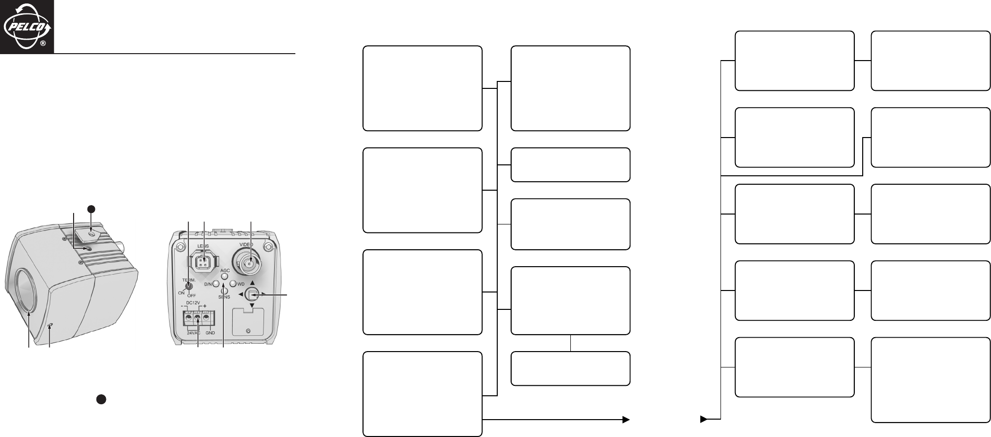
Lens Mount
Video Output Connector
Back Focus Locking Screw
Setup Button
Camera Mount and
3a
Adapter
Power Terminal Strip
Serial Terminating Switch
Indicators
Auto Iris Lens Connector
3a
SETUP MENUS
Use the setup menus to customize the camera settings. Refer to the setup menus as shown on this and
the opposite page.
MAIN MENU
PROFILES >
EXPOSURE SETTINGS >
FUNCTION SETTINGS >
CAMERA SETUP >
AI AUTO ADJUSTMENT >
PIXEL CORRECTION >
SYSTEM INFORMATION >
EXIT
PROFILES
ACTIVE > STANDARD
SAVE AS > CUSTOM
*DEFAULT STANDARD
BACK EXIT
EXPOSURE SETTINGS
AUTO EXPOSURE > NORMAL
VIDEO LEVEL > 0
FLICKERLESS > OFF
AGC > ON
DSS(SENS) > 4
DAY & NIGHT > COLOR
D&N DETECTION >
D&N FILTER LIMIT >
BACK EXIT
FUNCTION SETTINGS
LINE SYNC >
WHITE BALANCE > AUTO
MANUAL RED/BLUE >
GAMMA > 60%(NORM)
SHARPNESS >
E-ZOOM >
MASKING >
TITLE >
BACK EXIT
CAMERA SETUP
ADDRESS > 1
COM SPEED > 4800
LED > ON
SWITCH > ON
BACK EXIT
AI AUTO ADJUSTMENT
OK CANCEL
PIXEL CORRECTION
COVER THE LENS
AND SELECT OK
OK CANCEL
SYSTEM INFORMATION
FIRMWARE VERSION 1.0
OSD VERSION 1.0
RESTORE FACTORY SETTINGS >
BACK EXIT
RESTORE FACTORY SETTINGS
OK CANCEL
LINE SYNC
LINE SYNC > AUTO
V-PHASE ADJ >
BACK EXIT
V-PHASE ADJ
PHASE VALUE = 45
MANUAL RED/BLUE
RED GAIN > -1
BLUE GAIN > -2
RED HUE > 1
BLUE HUE > 1
BACK EXIT
SHARPNESS
APERTURE GAIN > -1
BACK EXIT
E-ZOOM
ZOOM > OFF
POSITION >
BACK EXIT
POSITION
MASKING
MASK > OFF
MASK EDIT >
MASK ERASE
BACK EXIT
MASK SETTING
TITLE
TITLE > OFF
EDIT TITLE >
BACK EXIT
EDIT TITLE
ABCDEFGHIJKLM
NOPQRSTUVWXYZ
abcdefghijklm
nopqrstuvwxyz
0123456789-/
BACK BS
________________
C2924M-QS.fm Page 1 Wednesday, April 27, 2005 3:26 PM

C2924M-QS (4/05)
LENS
The CCC1390H Series camera supports both manual and DC-drive auto iris lenses, either fixed focal
length or varifocal. It automatically senses an auto iris lens as soon as you plug in the connector.
The camera has a standard CS-mount that can accept a C-mount lens with a PCMA40 lens adapter.
To mount the lens onto the camera:
1. Use clean, compressed air or a clean, dry lens cloth to make sure there is no dust or other foreign
matter between the lens and the camera imager.
2.
C-mount lens:
Screw the adapter onto the lens.
3. Screw the lens onto the lens mount.
4.
DC-drive auto iris lens:
Connect the four-pin connector from the lens to the connector on the
back of the camera.
MOUNT
The CCC1390H Series camera can be mounted from either the top or bottom, depending on the type of
camera mount used in your installation. Use a standard 1/4-20 screw. The maximum thread depth (top)
is 0.188 inches (4.7 mm). To extend the thread depth (top) to 0.25 inches (6.4 mm), use the camera mount
spacer (supplied). The maximum thread depth (bottom) is 0.25 inches (6.4 mm).
ELECTRICAL
Power
Connect 12 VDC or 24 VAC power to the three-pin terminal strip on the back of the camera. Use a Class 2
isolated power source for the CCC1390H camera that can supply 12 VDC ±15% or 24 VAC ±15%,
50/60 Hz. Maximum power consumption is about 3.5 watts.
Video
Connect a coaxial video cable to the BNC connector on the back of the camera.
External Control
For serial control, install the control connector (refer to
Connecting External Control
in the Installation/
Operation manual for more information).
ACCESSING THE SETUP MENUS
Use the five-position button on the rear panel to access and navigate the setup menus. The following
table lists the button presses for each menu action.
MENU ACTION BUTTON ACTION
Enter setup menus. Long center press
Move up or down in menu or item options. Up or down press
Move right or left in menu. Right or left press
Select menu or item. Short center press
Save setting and exit to menu. Short center press
NOTE:
After you customize any aspect of the CCC1390H Series camera, be sure to save your custom
settings. (Refer to
Profiles
in the Installation/Operation manual for information about saving custom
settings.)
LENS FOCUS
After mounting the lens, you must focus your CCC1390H Series camera. You will adjust both the back
focus (on the camera) and the fine focus (on the lens).
NOTE:
The back focus has already been adjusted using a standard CS-mount lens. However, you might
need to adjust it again to match the mounted lens.
1.
Auto iris only:
Cover the auto iris lens
with a suitable neutral density (ND) filter.
This opens the iris fully. For best results,
use an ND3 filter.
2.
Manual iris only:
Open the iris
completely. The figure shows the manual
iris, varifocal, and lens focus locking
screws for a sample lens. Refer to your
lens documentation for more
information.
3. If necessary, enable Automatic Gain
Control (AGC) on the EXPOSURE
SETTINGS menu. AGC is enabled by
default.
a. Display the EXPOSURE
SETTINGS menu.
b. Change AGC to ON.
c. Select EXIT to save the AGC
setting.
4. Aim the camera at the farthest object in the field of view. Make sure it is at least 6.5 ft (2 m) away.
5.
Fixed focal length lens only:
a. Set the lens focal length to far (
∞
).
b. Adjust the back focus:
(1) Use a 1.5-mm Allen wrench to loosen the back focus locking screw.
(2) Turn the lens until the image is focused.
(3) Tighten the back focus locking screw clockwise.
Back focus is a coarse adjustment. You will make the fine focus adjustment in the next step.
c. Adjust the lens focus to achieve the best fine focus.
WARNING:
Do not over-tighten the back focus locking screw because you may damage the
camera.
1.5 MM
ALLEN
WRENCH
VARIFOCAL
LOCKING
SCREW
LENS FOCUS
LOCKING SCREW
MANUAL IRIS
LOCKING SCREW
6.
Varifocal lens only:
a. Set the varifocal to wide (W) and the lens focal length to far (
∞
).
b. Adjust the back focus:
(1) Use a 1.5-mm Allen wrench to loosen the back focus locking screw.
(2) Turn the lens until the image is focused.
(3) Tighten the back focus locking screw clockwise.
Back focus is a coarse adjustment. You will make the fine focus adjustment in steps c and d.
c. Move the varifocal locking screw up or down to set the field of view.
d. Adjust the lens focus to achieve the best fine focus.
e. Repeat steps c and d until the focus is correct.
7.
Manual iris only:
Adjust the iris for the best picture quality. The largest aperture gives the best
light sensitivity; the smallest aperture gives the greatest depth of field.
8. Tighten all lens locking screws.
NOTE:
When tightening the lens locking screws, do not over-turn or force any screw.
9.
Auto iris only:
Remove the ND filter.
10. If necessary, disable AGC:
a. Display the EXPOSURE SETTINGS menu.
b. Change AGC to OFF.
c. Select EXIT to save the AGC setting.
11.
Auto iris only:
Perform the auto iris lens adjustment procedure (refer to
Auto Iris Lens
Adjustment
in the Installation/Operation manual for more information).
12. As soon as you finish customizing this and all other camera settings, save your custom settings
into the CUSTOM profile. This protects them in case the camera loses power or must be restarted
(refer to
Profiles
in the Installation/Operation manual for more information).
WARNING:
Do not over-tighten the back focus locking screw because you may damage the
camera.
REVISION HISTORY
Manual # Date Comments
C2924M-QS 4/05 Original version.
Pelco and the Pelco logo are registered trademarks of Pelco. ©Copyright 2005, Pelco. All rights reserved.
Worldwide Headquarters • 3500 Pelco Way • Clovis, California 93612 USA • www.pelco.com
USA & Canada • Tel: 800/289-9100 • Fax: 800/289-9150
International • Tel: 1-559/292-1981 • Fax: 1-559/348-1120
C2924M-QS.fm Page 2 Wednesday, April 27, 2005 3:26 PM
