Pelco EW5000SERIES Video Encoder, Video Access Point/Bridge User Manual C2677M
Pelco Video Encoder, Video Access Point/Bridge C2677M
UserManual.wiki
>
Pelco
>
EW5000SERIES User Manual
>
manual
Contents
1.
manual
2.
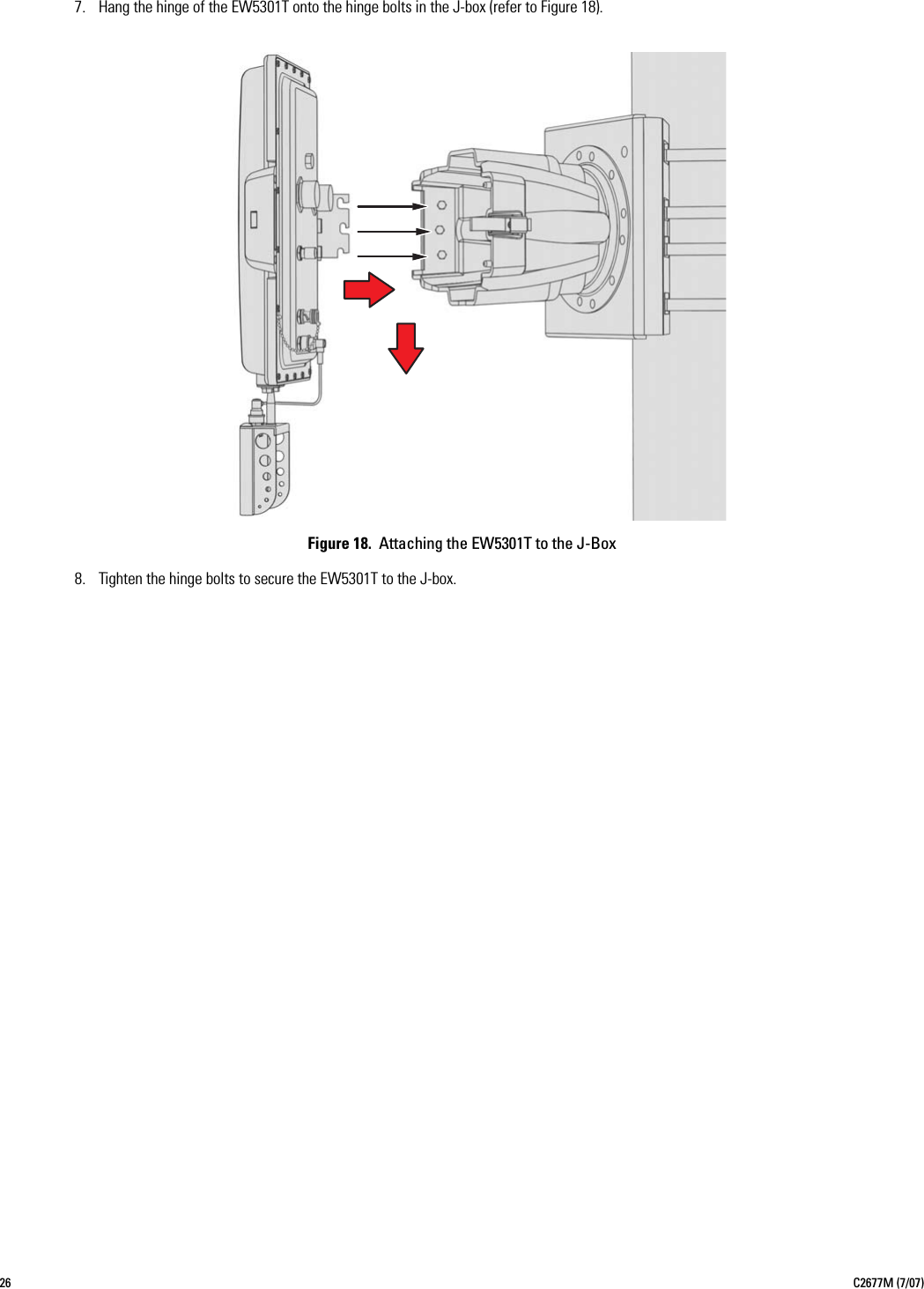
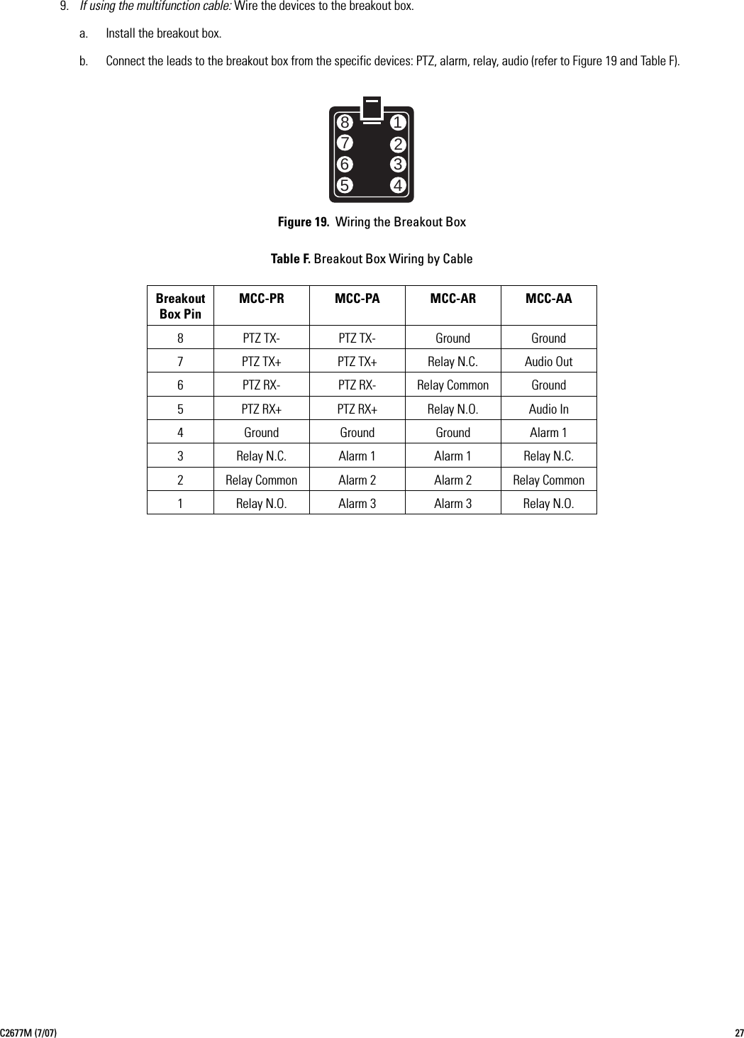
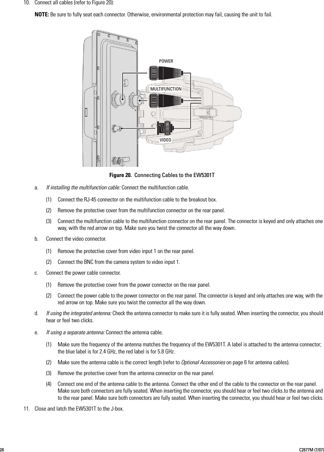
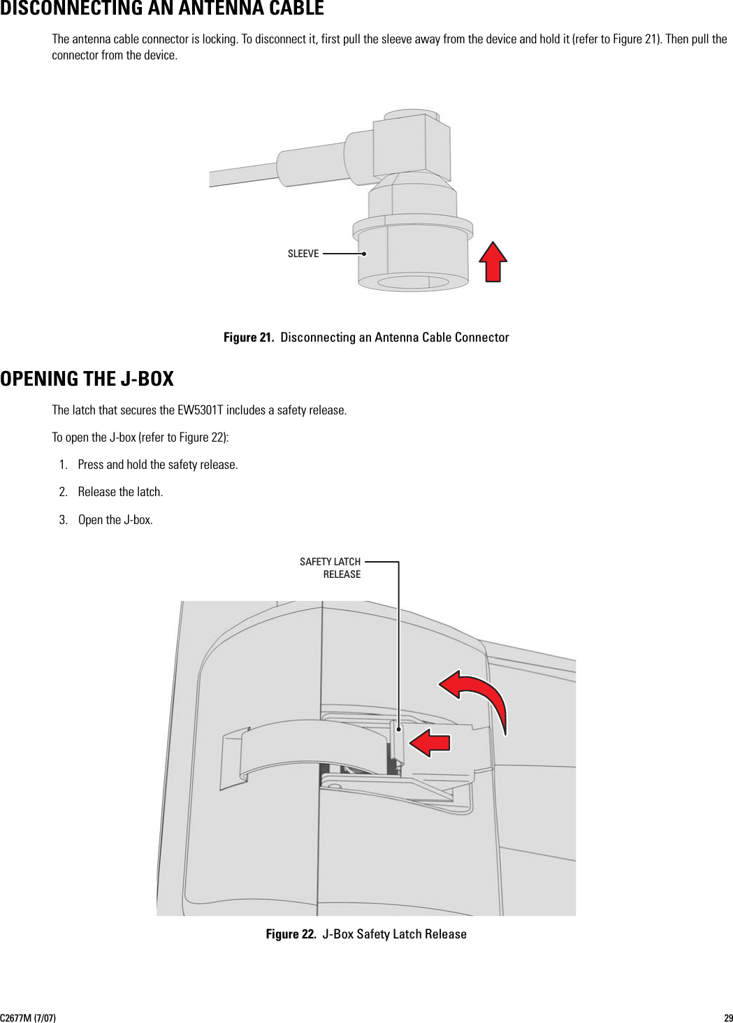
Manual
manual
Navigation menu
Upload a User Manual
Namespaces
Wiki Guide
HTML
PDF
Info
Views
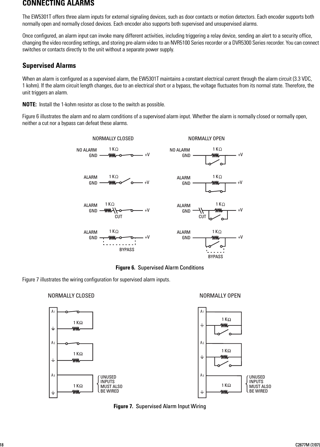
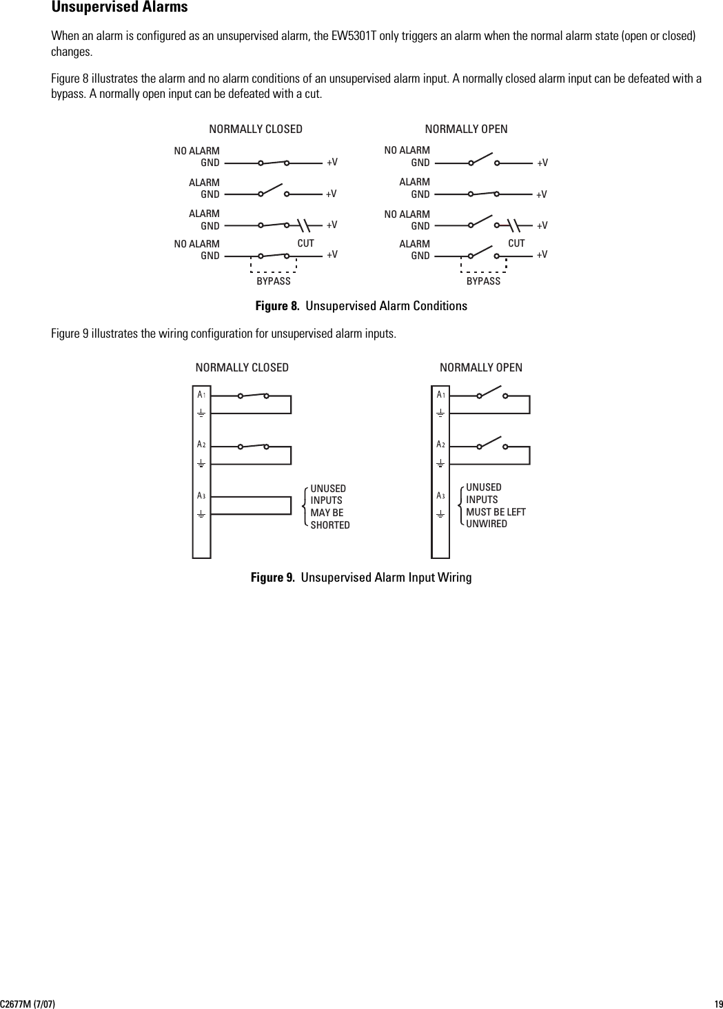
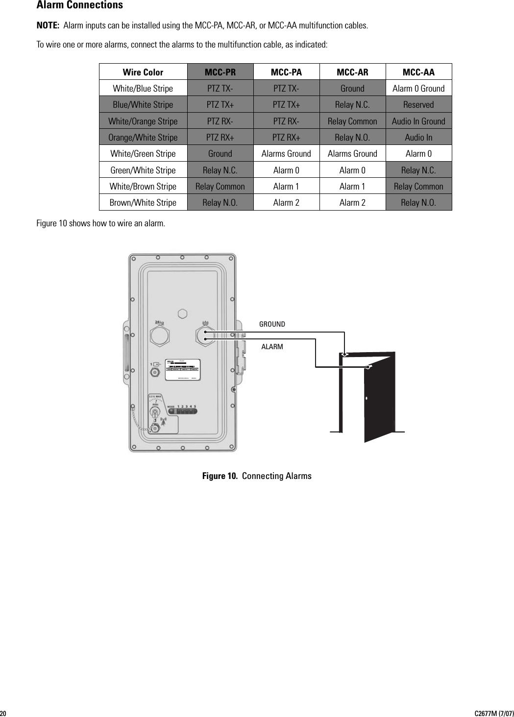
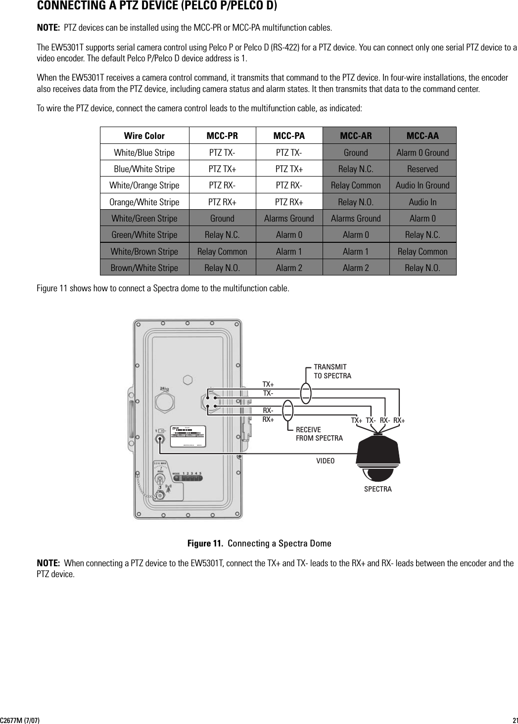
User Manual
Discussion / Help
Navigation