Pelco EW5000SERIES Video Encoder, Video Access Point/Bridge User Manual C2677M
Pelco Video Encoder, Video Access Point/Bridge C2677M
Pelco >
Contents
- 1. manual
- 2. Manual
manual

Endura™ EW5301T
Wireless Video
Encoder
INSTALLATION
C2677M (7/07)
August 3, 2007 8:10 am

C2677M (7/07) 3
Contents
Regulatory Notices . . . . . . . . . . . . . . . . . . . . . . . . . . . . . . . . . . . . . . . . . . . . . . . . . . . . . . . . . . . . . . . . . . . . . . . . . . . . . . . . . . . . . . . . . . . . . . . . . . . . 5
Exposure to Radio Frequency Fields . . . . . . . . . . . . . . . . . . . . . . . . . . . . . . . . . . . . . . . . . . . . . . . . . . . . . . . . . . . . . . . . . . . . . . . . . . . . . . . . . . 5
Description . . . . . . . . . . . . . . . . . . . . . . . . . . . . . . . . . . . . . . . . . . . . . . . . . . . . . . . . . . . . . . . . . . . . . . . . . . . . . . . . . . . . . . . . . . . . . . . . . . . . . . . . . . 6
Models . . . . . . . . . . . . . . . . . . . . . . . . . . . . . . . . . . . . . . . . . . . . . . . . . . . . . . . . . . . . . . . . . . . . . . . . . . . . . . . . . . . . . . . . . . . . . . . . . . . . . . . . . 6
Optional Accessories . . . . . . . . . . . . . . . . . . . . . . . . . . . . . . . . . . . . . . . . . . . . . . . . . . . . . . . . . . . . . . . . . . . . . . . . . . . . . . . . . . . . . . . . . . . . . . 6
Before You Begin . . . . . . . . . . . . . . . . . . . . . . . . . . . . . . . . . . . . . . . . . . . . . . . . . . . . . . . . . . . . . . . . . . . . . . . . . . . . . . . . . . . . . . . . . . . . . . . . . . . . . 7
Parts List . . . . . . . . . . . . . . . . . . . . . . . . . . . . . . . . . . . . . . . . . . . . . . . . . . . . . . . . . . . . . . . . . . . . . . . . . . . . . . . . . . . . . . . . . . . . . . . . . . . . . . . 7
Package Contents . . . . . . . . . . . . . . . . . . . . . . . . . . . . . . . . . . . . . . . . . . . . . . . . . . . . . . . . . . . . . . . . . . . . . . . . . . . . . . . . . . . . . . . . . . . . . . . . 8
Application Scenario . . . . . . . . . . . . . . . . . . . . . . . . . . . . . . . . . . . . . . . . . . . . . . . . . . . . . . . . . . . . . . . . . . . . . . . . . . . . . . . . . . . . . . . . . . . . . . 9
Product Serial Number Label Placement . . . . . . . . . . . . . . . . . . . . . . . . . . . . . . . . . . . . . . . . . . . . . . . . . . . . . . . . . . . . . . . . . . . . . . . . . . . . . . 10
Site Preparation . . . . . . . . . . . . . . . . . . . . . . . . . . . . . . . . . . . . . . . . . . . . . . . . . . . . . . . . . . . . . . . . . . . . . . . . . . . . . . . . . . . . . . . . . . . . . . . . . . . . . 11
Site Selection . . . . . . . . . . . . . . . . . . . . . . . . . . . . . . . . . . . . . . . . . . . . . . . . . . . . . . . . . . . . . . . . . . . . . . . . . . . . . . . . . . . . . . . . . . . . . . . . . . . 11
Mount Installation . . . . . . . . . . . . . . . . . . . . . . . . . . . . . . . . . . . . . . . . . . . . . . . . . . . . . . . . . . . . . . . . . . . . . . . . . . . . . . . . . . . . . . . . . . . . . . . 12
Power Wiring . . . . . . . . . . . . . . . . . . . . . . . . . . . . . . . . . . . . . . . . . . . . . . . . . . . . . . . . . . . . . . . . . . . . . . . . . . . . . . . . . . . . . . . . . . . . . . . . . . . 13
Camera System Installation . . . . . . . . . . . . . . . . . . . . . . . . . . . . . . . . . . . . . . . . . . . . . . . . . . . . . . . . . . . . . . . . . . . . . . . . . . . . . . . . . . . . . . . . 14
Multifunction Cable Wiring . . . . . . . . . . . . . . . . . . . . . . . . . . . . . . . . . . . . . . . . . . . . . . . . . . . . . . . . . . . . . . . . . . . . . . . . . . . . . . . . . . . . . . . . 15
Connecting Audio . . . . . . . . . . . . . . . . . . . . . . . . . . . . . . . . . . . . . . . . . . . . . . . . . . . . . . . . . . . . . . . . . . . . . . . . . . . . . . . . . . . . . . . . . . . 16
Connecting a Relay Device . . . . . . . . . . . . . . . . . . . . . . . . . . . . . . . . . . . . . . . . . . . . . . . . . . . . . . . . . . . . . . . . . . . . . . . . . . . . . . . . . . . . 17
Connecting Alarms . . . . . . . . . . . . . . . . . . . . . . . . . . . . . . . . . . . . . . . . . . . . . . . . . . . . . . . . . . . . . . . . . . . . . . . . . . . . . . . . . . . . . . . . . . 18
Connecting a PTZ Device (Pelco P/Pelco D) . . . . . . . . . . . . . . . . . . . . . . . . . . . . . . . . . . . . . . . . . . . . . . . . . . . . . . . . . . . . . . . . . . . . . . . 21
Antenna Installation . . . . . . . . . . . . . . . . . . . . . . . . . . . . . . . . . . . . . . . . . . . . . . . . . . . . . . . . . . . . . . . . . . . . . . . . . . . . . . . . . . . . . . . . . . . . . 22
Bench Setup (Optional) . . . . . . . . . . . . . . . . . . . . . . . . . . . . . . . . . . . . . . . . . . . . . . . . . . . . . . . . . . . . . . . . . . . . . . . . . . . . . . . . . . . . . . . . . . . 22
Unit Installation . . . . . . . . . . . . . . . . . . . . . . . . . . . . . . . . . . . . . . . . . . . . . . . . . . . . . . . . . . . . . . . . . . . . . . . . . . . . . . . . . . . . . . . . . . . . . . . . . . . . . 23
Disconnecting an Antenna Cable . . . . . . . . . . . . . . . . . . . . . . . . . . . . . . . . . . . . . . . . . . . . . . . . . . . . . . . . . . . . . . . . . . . . . . . . . . . . . . . . . . . 29
Opening the J-Box . . . . . . . . . . . . . . . . . . . . . . . . . . . . . . . . . . . . . . . . . . . . . . . . . . . . . . . . . . . . . . . . . . . . . . . . . . . . . . . . . . . . . . . . . . . . . . . 29
Antenna Alignment . . . . . . . . . . . . . . . . . . . . . . . . . . . . . . . . . . . . . . . . . . . . . . . . . . . . . . . . . . . . . . . . . . . . . . . . . . . . . . . . . . . . . . . . . . . . . . . . . . . 30
Indicators . . . . . . . . . . . . . . . . . . . . . . . . . . . . . . . . . . . . . . . . . . . . . . . . . . . . . . . . . . . . . . . . . . . . . . . . . . . . . . . . . . . . . . . . . . . . . . . . . . . . . . . . . . 31
Indicators During Startup . . . . . . . . . . . . . . . . . . . . . . . . . . . . . . . . . . . . . . . . . . . . . . . . . . . . . . . . . . . . . . . . . . . . . . . . . . . . . . . . . . . . . . . . . . 31
Indicators During Operation . . . . . . . . . . . . . . . . . . . . . . . . . . . . . . . . . . . . . . . . . . . . . . . . . . . . . . . . . . . . . . . . . . . . . . . . . . . . . . . . . . . . . . . . 32
Configuration and Operation . . . . . . . . . . . . . . . . . . . . . . . . . . . . . . . . . . . . . . . . . . . . . . . . . . . . . . . . . . . . . . . . . . . . . . . . . . . . . . . . . . . . . . . . . . . 33
Troubleshooting . . . . . . . . . . . . . . . . . . . . . . . . . . . . . . . . . . . . . . . . . . . . . . . . . . . . . . . . . . . . . . . . . . . . . . . . . . . . . . . . . . . . . . . . . . . . . . . . . . . . . 34
Specifications . . . . . . . . . . . . . . . . . . . . . . . . . . . . . . . . . . . . . . . . . . . . . . . . . . . . . . . . . . . . . . . . . . . . . . . . . . . . . . . . . . . . . . . . . . . . . . . . . . . . . . . 35

4C2677M (7/07)
List of Illustrations
1 Package Conten ts . . . . . . . . . . . . . . . . . . . . . . . . . . . . . . . . . . . . . . . . . . . . . . . . . . . . . . . . . . . . . . . . . . . . . . . . . . . . . . . . . . . . . . . . . . . . . . . . . 8
2 Sample EW5301T Ap plication Scenario . . . . . . . . . . . . . . . . . . . . . . . . . . . . . . . . . . . . . . . . . . . . . . . . . . . . . . . . . . . . . . . . . . . . . . . . . . . . . . . . 9
3 Product Serial Number Label . . . . . . . . . . . . . . . . . . . . . . . . . . . . . . . . . . . . . . . . . . . . . . . . . . . . . . . . . . . . . . . . . . . . . . . . . . . . . . . . . . . . . . . 10
4 Connecting an Audio Device. . . . . . . . . . . . . . . . . . . . . . . . . . . . . . . . . . . . . . . . . . . . . . . . . . . . . . . . . . . . . . . . . . . . . . . . . . . . . . . . . . . . . . . . 16
5 Connecting a Relay Device . . . . . . . . . . . . . . . . . . . . . . . . . . . . . . . . . . . . . . . . . . . . . . . . . . . . . . . . . . . . . . . . . . . . . . . . . . . . . . . . . . . . . . . . . 17
6 Supervised Alarm Conditions . . . . . . . . . . . . . . . . . . . . . . . . . . . . . . . . . . . . . . . . . . . . . . . . . . . . . . . . . . . . . . . . . . . . . . . . . . . . . . . . . . . . . . . 18
7 Supervised Alarm Input Wiring . . . . . . . . . . . . . . . . . . . . . . . . . . . . . . . . . . . . . . . . . . . . . . . . . . . . . . . . . . . . . . . . . . . . . . . . . . . . . . . . . . . . . 18
8 Unsupervised Alarm Conditions . . . . . . . . . . . . . . . . . . . . . . . . . . . . . . . . . . . . . . . . . . . . . . . . . . . . . . . . . . . . . . . . . . . . . . . . . . . . . . . . . . . . . 19
9 Unsupervised Alarm Input Wiring . . . . . . . . . . . . . . . . . . . . . . . . . . . . . . . . . . . . . . . . . . . . . . . . . . . . . . . . . . . . . . . . . . . . . . . . . . . . . . . . . . . 19
10 Connecting Alarms . . . . . . . . . . . . . . . . . . . . . . . . . . . . . . . . . . . . . . . . . . . . . . . . . . . . . . . . . . . . . . . . . . . . . . . . . . . . . . . . . . . . . . . . . . . . . . . 20
11 Connecting a Spectra Dome . . . . . . . . . . . . . . . . . . . . . . . . . . . . . . . . . . . . . . . . . . . . . . . . . . . . . . . . . . . . . . . . . . . . . . . . . . . . . . . . . . . . . . . . 21
12 Attaching the Integrated Antenna . . . . . . . . . . . . . . . . . . . . . . . . . . . . . . . . . . . . . . . . . . . . . . . . . . . . . . . . . . . . . . . . . . . . . . . . . . . . . . . . . . . 23
13 Connecting the Antenna Cable. . . . . . . . . . . . . . . . . . . . . . . . . . . . . . . . . . . . . . . . . . . . . . . . . . . . . . . . . . . . . . . . . . . . . . . . . . . . . . . . . . . . . . 23
14 J-Box Orientation . . . . . . . . . . . . . . . . . . . . . . . . . . . . . . . . . . . . . . . . . . . . . . . . . . . . . . . . . . . . . . . . . . . . . . . . . . . . . . . . . . . . . . . . . . . . . . . . 24
15 Installing the J-Box (EWM shown). . . . . . . . . . . . . . . . . . . . . . . . . . . . . . . . . . . . . . . . . . . . . . . . . . . . . . . . . . . . . . . . . . . . . . . . . . . . . . . . . . . 24
16 Removing an Auxiliary Opening Plug . . . . . . . . . . . . . . . . . . . . . . . . . . . . . . . . . . . . . . . . . . . . . . . . . . . . . . . . . . . . . . . . . . . . . . . . . . . . . . . . . 25
17 Routing Power, Video, and Multifunction Cables. . . . . . . . . . . . . . . . . . . . . . . . . . . . . . . . . . . . . . . . . . . . . . . . . . . . . . . . . . . . . . . . . . . . . . . . 25
18 Attaching the EW5301T to the J-Box. . . . . . . . . . . . . . . . . . . . . . . . . . . . . . . . . . . . . . . . . . . . . . . . . . . . . . . . . . . . . . . . . . . . . . . . . . . . . . . . . 26
19 Wiring the Breakout Box. . . . . . . . . . . . . . . . . . . . . . . . . . . . . . . . . . . . . . . . . . . . . . . . . . . . . . . . . . . . . . . . . . . . . . . . . . . . . . . . . . . . . . . . . . . 27
20 Connecting Cables to the EW5301T. . . . . . . . . . . . . . . . . . . . . . . . . . . . . . . . . . . . . . . . . . . . . . . . . . . . . . . . . . . . . . . . . . . . . . . . . . . . . . . . . . 28
21 Disconnecting an Antenna Cable Connector . . . . . . . . . . . . . . . . . . . . . . . . . . . . . . . . . . . . . . . . . . . . . . . . . . . . . . . . . . . . . . . . . . . . . . . . . . . 29
22 J-Box Safety Latch Release . . . . . . . . . . . . . . . . . . . . . . . . . . . . . . . . . . . . . . . . . . . . . . . . . . . . . . . . . . . . . . . . . . . . . . . . . . . . . . . . . . . . . . . . 29
23 Connecting a DVM to the EW5301T. . . . . . . . . . . . . . . . . . . . . . . . . . . . . . . . . . . . . . . . . . . . . . . . . . . . . . . . . . . . . . . . . . . . . . . . . . . . . . . . . . 30
24 EW5301T Status Indicators . . . . . . . . . . . . . . . . . . . . . . . . . . . . . . . . . . . . . . . . . . . . . . . . . . . . . . . . . . . . . . . . . . . . . . . . . . . . . . . . . . . . . . . . 31
List of Tables
A Compatible Pelco Mounts . . . . . . . . . . . . . . . . . . . . . . . . . . . . . . . . . . . . . . . . . . . . . . . . . . . . . . . . . . . . . . . . . . . . . . . . . . . . . . . . . . . . . . . . . 12
B 24 VAC Wiring Distance . . . . . . . . . . . . . . . . . . . . . . . . . . . . . . . . . . . . . . . . . . . . . . . . . . . . . . . . . . . . . . . . . . . . . . . . . . . . . . . . . . . . . . . . . . 13
C Video Coaxial Cable Requirements . . . . . . . . . . . . . . . . . . . . . . . . . . . . . . . . . . . . . . . . . . . . . . . . . . . . . . . . . . . . . . . . . . . . . . . . . . . . . . . . . . 14
D Multifunction Cable Wiring . . . . . . . . . . . . . . . . . . . . . . . . . . . . . . . . . . . . . . . . . . . . . . . . . . . . . . . . . . . . . . . . . . . . . . . . . . . . . . . . . . . . . . . . 15
E Serial Port Options and Defaults . . . . . . . . . . . . . . . . . . . . . . . . . . . . . . . . . . . . . . . . . . . . . . . . . . . . . . . . . . . . . . . . . . . . . . . . . . . . . . . . . . . . 22
F Breakout Box Wiring by Cable . . . . . . . . . . . . . . . . . . . . . . . . . . . . . . . . . . . . . . . . . . . . . . . . . . . . . . . . . . . . . . . . . . . . . . . . . . . . . . . . . . . . . . 27
G Indicators During Startup . . . . . . . . . . . . . . . . . . . . . . . . . . . . . . . . . . . . . . . . . . . . . . . . . . . . . . . . . . . . . . . . . . . . . . . . . . . . . . . . . . . . . . . . . . 31
H Indicators During Operation . . . . . . . . . . . . . . . . . . . . . . . . . . . . . . . . . . . . . . . . . . . . . . . . . . . . . . . . . . . . . . . . . . . . . . . . . . . . . . . . . . . . . . . . 32
I Troubleshooting the EW5301T . . . . . . . . . . . . . . . . . . . . . . . . . . . . . . . . . . . . . . . . . . . . . . . . . . . . . . . . . . . . . . . . . . . . . . . . . . . . . . . . . . . . . 34

C2677M (7/07) 5
Regulatory Notices
This device complies with Part 15 of the FCC Rules. Operation is subject to the following two conditions: (1) this device may not cause harmful
interference, and (2) this device must accept any interference received, including interference that may cause undesired operation.
RADIO AND TELEVISION INTERFERENCE
This equipment has been tested and found to comply with the limits of a Class A digital device, pursuant to Part 15 of the FCC Rules. These limits
are designed to provide reasonable protection against harmful interference when the equipment is operated in a commercial environment. This
equipment generates, uses, and can radiate radio frequency energy and, if not installed and used in accordance with the instruction manual, may
cause harmful interference to radio communications. Operation of this equipment in a residential area is likely to cause harmful interference in
which case the user will be required to correct the interference at his own expense.
Changes and modifications not expressly approved by the manufacturer or registrant of this equipment can void your authority to operate this
equipment under Federal Communications Commission’s rules.
In order to maintain compliance with FCC regulations, shielded cables must be used with this equipment. Operation with non-approved
equipment or unshielded cables is likely to result in interference to radio and television reception.
This Class A digital apparatus complies with Canadian ICES-003.
Cet appareil numérique de la classe A est conforme à la norme NMB-003 du Canada.
EXPOSURE TO RADIO FREQUENCY FIELDS
The EW5301T is designed to operate at 2.4 GHz or 5.8 GHz with up to 50 W equivalent isotropically radiated power (EIRP) maximum transmit
power. This level of radio frequency (RF) energy is above the Maximum Permissible Exposure (MPE) levels specified in FCC OET65:97-01. Take the
following precautions during installation:
• The antennas used for this transmitter must be installed to provide a separation distance of at least 8 in. (20 cm) from all persons. It must
not be located or operated in conjunction with any other antenna or transmitter.
• Mount the antenna in a manner that prevents any personnel from entering the area within 3.3 ft (1 m) of the front of the antenna.
• During installation and alignment of the antenna, do not stand in front of the antenna assembly.
• During installation and alignment of the antenna, do not handle or touch the front of the antenna.
Video Quality Caution
FRAME RATE NOTICE REGARDING USER-SELECTED OPTIONS
Pelco systems are capable of providing high quality video for both live viewing and playback. However, the systems can be used in lower quality
modes, which can degrade picture quality, to allow for a slower rate of data transfer and to reduce the amount of video data stored. The picture
quality can be degraded by either lowering the resolution, reducing the picture rate, or both. A picture degraded by having a reduced resolution
may result in an image that is less clear or even indiscernible. A picture degraded by reducing the picture rate has fewer frames per second,
which can result in images that appear to jump or move more quickly than normal during playback. Lower frame rates may result in a key event
not being recorded by the system.
Judgment as to the suitability of the products for users’ purposes is solely the users’ responsibility. Users shall determine the suitability of the
products for their own intended application, picture rate and picture quality. In the event users intend to use the video for evidentiary purposes in
a judicial proceeding or otherwise, users should consult with their attorney regarding any particular requirements for such use.

6C2677M (7/07)
Description
The EW5301T wireless video encoder is a high-performance, dual-stream, single-input video encoding unit. Its main function is to convert live
analog video into dual MPEG-4 video streams. It transmits these streams to an Endura™ EW5001 or EW5002 wireless access point, which
transmits the streams over an Ethernet network to other Endura system components. Then these streams can be recorded on an Endura NVR5100
Series network video recorder or DVR5300 Series digital video recorder, or decoded by the following Endura components:
• NET5301R video decoder: Converts up to 4 video streams for display or recording on an analog device.
• Endura Workstation: Converts up to 16 video streams for display on a computer monitor.
• VCD5000 video console display: Converts up to 64 video streams (depending on model) for display or recording on an analog device.
The EW5301T incorporates EnduraView™ video optimization technology to select the best image quality and frame rate for the target Endura
product (decoder, workstation, console), all without affecting the system recording rate. For example, the unit selects a high rate and quality
setting for recording and alarm conditions; it selects a lower rate for simple monitoring.
The EW5301T automatically detects the video standard (PAL or NTSC) and accepts both color and black-white analog video.
The EW5301T can be configured for three alarm inputs and one relay output. When an alarm event is triggered, the unit can send a message to
an operator, trigger a relay, and implement video recording.
The unit also supports activity detection. You can configure up to three activity zones, each with its own independent sensitivity and threshold
settings. When the EW5301T detects activity in any of these areas, it can trigger an alarm event.
The video encoder supports one audio input over the network. The system operator (security personnel) can see and hear activity in the target
area.
All Endura products support Pelco P/Pelco D and Coaxitron® protocols. As a result, the EW5301T supports control of remote peripherals such as
pan/tilt/zoom (PTZ) cameras.
You can associate a cluster of EW5301T video encoders with an EW5001 that is configured as an access point. If you configure an EW5002 with two
access points, you can associate one cluster with one access point and another cluster with the second access point. Refer to Application Scenario on
page 9 and Site Selection on page 11 for more information.
MODELS
EW5301T-2-xx* Wireless video encoder, 2.4 GHz, planar antenna with integrated mount and cable, 8.5 dBi gain, 75° x 60° beamwidth
EW5301T-5-xx* Wireless video encoder, 5.8 GHz, planar antenna with integrated mount and cable, 13.5 dBi gain, 40° x 35° beamwidth
*-xx represents region code; for example, -01 for the United States and Canada.
OPTIONAL ACCESSORIES
ANTP-2-9 Replacement planar antenna with integrated mount and cable for EW5301T-2 units, 2.4 GHz, 8.5 dBi gain,
75° x 60° beamwidth
ANTP-5-15 Replacement planar antenna with integrated mount and cable for EW5301T-5 units, 5.8 GHz, 13.5 dBi gain,
40° x 35° beamwidth
ANTP-5-23 Planar antenna with mount for EW5301T-5 units, 5.8 GHz, 23.0 dBi gain, 9° x 9° beamwidth
ANTG-2-14 Grid parabolic dish antenna with mount for EW5301T-2 units, 2.4 GHz, 14.0 dBi gain, 21° x 14° beamwidth
ANTC-06 Replacement 7-inch (17.78 cm) antenna cable for integrated antenna
ANTC-3 3-foot (0.91 m) antenna cable for separate antenna
ANTC-10 10-foot (3.05 m) antenna cable for separate antenna
MCC-PR Multifunction cable for serial PTZ and relay support; includes breakout box
MCC-PA Multifunction cable for serial PTZ and alarm support; includes breakout box
MCC-AR Multifunction cable for alarm and relay support; includes breakout box
MCC-AA Multifunction cable for alarm, relay, and audio support; includes breakout box

C2677M (7/07) 7
Before You Begin
Endura is a network system that requires a continuous amount of bandwidth to transmit true, live video. Therefore, always include your network
administrator when planning and installing Endura components.
You will also need the following:
• Pelco-approved Endura certification
• Power source
• One analog video device (fixed or PTZ camera)
• Microphone (if using audio)
• Access to an Endura network
– that is an active, gigabit Ethernet network that supports the full Internet Protocol suite,
– that is configured with at least one NVR5100 Series network video recorder or other Endura video recorder,
– that is configured with at least one Endura Workstation, and
– that is configured with at least one wireless access point (EW5001 or EW5002).
•7/16-inch wrench
• Digital voltmeter (DVM) with BNC adapter
• Any tools required for installing the specific mount (refer to the mount documentation)
NOTE: These network requirements represent the minimum standard for a small Endura-capable security network. Please consult the Endura
Network Design Guide (C1640M) to make sure your network is properly configured. Your system may be different and may require additional
hardware, software, and network resources.
PARTS LIST
Qty Description
1 EW5301T wireless video encoder:
• Video encoder
• Junction box (J-box)
1 Integrated planar antenna
1 7-inch (17.78 cm) antenna cable
1 Power connector and cable
1 EW5301T installation manual
1 EW5301T configuration manual
1 Antenna installation manual
1 Safety instructions
NOTE: The multifunction cable is not included with the EW5301T. It must be purchased separately (refer to Optional Accessories on page 6). The
breakout box is included with each multifunction cable.
8C2677M (7/07)
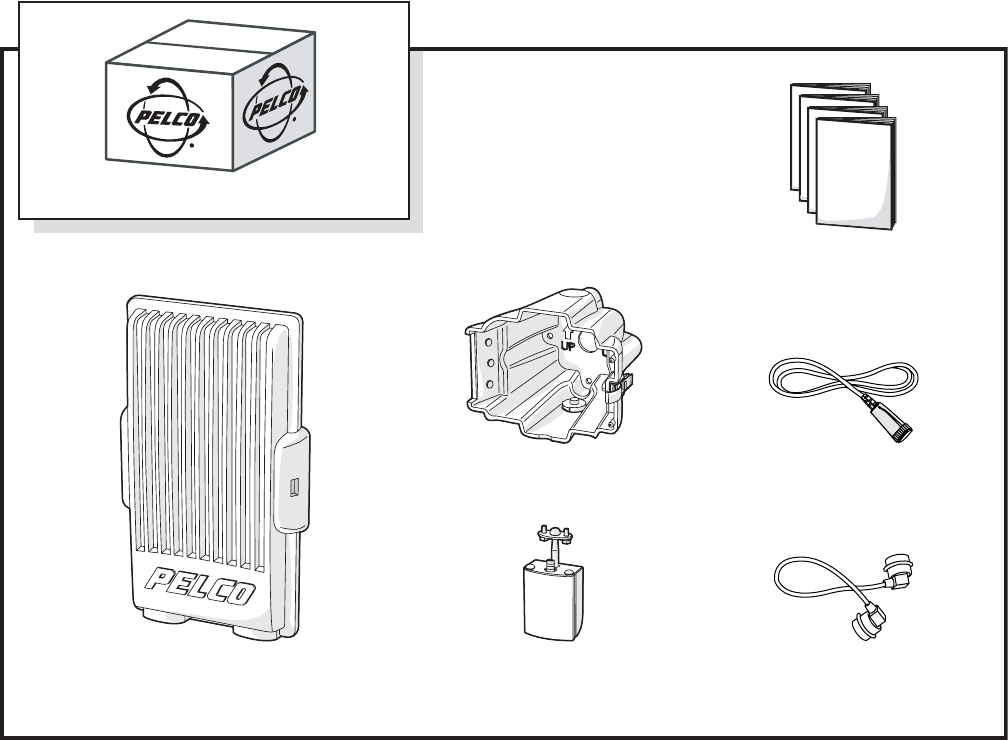
PACKAGE CONTENTS
The following diagram shows the contents of the box.
Figure 1. Package Contents
SHIPPING BOX
ANTENNA CABLE
POWER CONNECTOR
AND CABLE
INSTALLATION MANUALS (2),
CONFIGURATION MANUAL,
SAFETY INSTRUCTIONS
INTEGRATED
ANTENNA
J-BOX
EW5301T
C2677M (7/07) 9
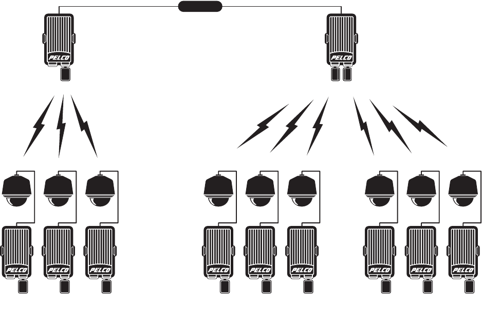
APPLICATION SCENARIO
Figure 2 shows clusters of EW5301T video encoders in a sample application scenario. The EW5001 is configured as an access point for one
cluster. The EW5002 is configured as two access points; each access point serves one cluster. In most installations, the EW5002 would use
different radio frequencies for each cluster. Refer to Site Selection on page 11 for more information.
Figure 2. Sample EW5301T Application Scenario
IMPORTANT NOTE. PLEASE READ. The network implementation in this document is shown as a general representation only and is not
intended to show detailed network topologies. Your actual network will differ, requiring changes or perhaps additional network equipment to
accommodate the system as illustrated. Please contact your local Pelco Representative to discuss your specific requirements.
EW5301T UNITS
CAMERACAMERACAMERA
EW5301T UNITS
CAMERACAMERACAMERA
EW5301T UNITS
CAMERACAMERACAMERA
EW5002EW5001
NETWORK
10 C2677M (7/07)
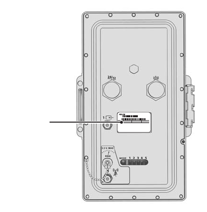
PRODUCT SERIAL NUMBER LABEL PLACEMENT
Product serial number labels help Pelco’s Product Support identify your system and its factory configuration in case the EW5301T or its
components require service.
A label citing your product’s serial number is attached to the rear panel of the EW5301T. Because the label will be covered by the J-box
(supplied), two additional labels are provided. These additional labels also list the MAC (Media Access Control) or network adapter address for
the unit. Attach one of them to your product documentation or other location. The second label is a spare.
To use these labels:
1. On the rear panel of your EW5301T, locate two small labels, attached with a yellow sticker that reads, “Extra serial number labels: remove
prior to installation.”
2. Remove the yellow sticker and the labels.
3. Peel away the backing from one label and attach it to this installation manual, other product documentation, or other location.
Figure 3. Product Serial Number Label
MODEL
FREQ
50/60HZ
Sample Text
AMPS
VOLTS
Sample Text
REV
Sample Text
MFG BY PELCO, CLOVIS, CA
Model
SN
MADE IN USA
PRODUCT LABEL

C2677M (7/07) 11
Site Preparation
Before you install the EW5301T, complete the following:
• Select a site for the EW5301T.
• Install a mount for the EW5301T.
• Wire the site for power.
• Install the camera system.
• Wire the multifunction cable for any audio, alarms, relays, and serial PTZ control lines.
• Install the antenna.
•Optional: Configure the network and wireless settings for the EW5301T on a workbench.
SITE SELECTION
Site selection should be performed by a Pelco-certified wireless design consultant, who will address the following issues as part of their site
plan. Then follow the design as specified by the consultant.
The EW5301T uses radio waves to communicate with an EW5001 or EW5002 unit in access point mode. Select a location with clear line-of-sight
from the EW5301T to the EW5001 or EW5002. Buildings, trees, and other obstacles will affect communication.
Maximum distance from the EW5301T to an EW5001 or an EW5002 access point is affected by site characteristics, unit transmission rate, and
antenna options. It is also affected by the “noise floor.” The noise floor is the sum of all noise sources and unwanted signals in the area between
transmitter and receiver. It may include thermal noise, objects between transmitter and receiver, and any interfering signals.

12 C2677M (7/07)
MOUNT INSTALLATION
The EW5301T includes two major mounting components. The unit itself attaches to the J-box. The J-box attaches to any mount with a standard
Pelco four-bolt pattern.
Before selecting a mount, plan the wiring paths for power, video, serial PTZ control, alarm, relay, and audio. The J-box has three openings: one on
the top, one on the bottom, and one in the mount surface. Select a mount that facilitates the wiring paths. Table A lists compatible Pelco mounts:
Table A. Compatible Pelco Mounts
NOTE: Make sure the mount supports at least 25 lbs (11.4 kg) for the EW5301T. If installing additional equipment to the mount, make sure the
mount will support the total weight of the EW5301T and the additional equipment.
Install the mount (refer to the mount documentation for more information).
Mount Description Required Adapter Maximum Load
EPM Esprit pole mount
with center feedthrough hole
None 100 lbs (45 kg)
PA402 Pole mount EA4348 adapter plate 75 lbs (34 kg)
CM100 Corner mount None 75 lbs (34 kg)
CM400 Corner mount EA4348 adapter plate 75 lbs (34 kg)
ECM100 Esprit corner mount
with center feedthrough hole
None 75 lbs (34 kg)
PP100 Parapet mount None 75 lbs (34 kg)
PP300L/PP301L Parapet corner mount EA4348 adapter plate 175 lbs (79 kg)
PP400 Parapet mount EA4348 adapter plate 75 lbs (34 kg)
PP4348 Parapet rooftop mount EA4348 adapter plate 75 lbs (34 kg)

C2677M (7/07) 13
POWER WIRING
The EW5301T video encoder is designed to operate from either a 12 VDC or a 24 VAC power supply. It automatically senses power type and
polarity (DC). The unit can be powered from a Pelco WCS Series power supply or any other environmentally rated power unit that supplies
12 VDC ±10% or 24 VAC ±10%. Unit power consumption is 14 W (23.3 VA).
Be sure to supply adequate power to the site for the EW5301T (23.3 VA) as well as the camera system and any alarms, relays, or audio
equipment. Table B identifies the necessary wire gauge and maximum cable distance to supply power to the mount site. This table applies to
2-conductor solid copper wire. (Reduce distance by 10 percent for stranded copper wire.) These are the recommended maximum distances for 24
VAC applications and are based on a maximum allowable voltage drop of 10 percent.
The EW5301T includes a 10-foot (3 m) cable with an environmentally-rated plug for connecting power to the unit. Connect the power lines to the
power cable at the mount site, as indicated (refer to Unit Installation on page 23 for more information):
NOTES:
• Be sure to use environmentally-rated connectors when connecting power to the EW5301T. Otherwise, unit reliability may suffer.
• The power cable may include other leads that are not be used.
• Installers should consult local, state, and federal code requirements before installing this cable or running this cable inside any building.
Installers should also use best practices when terminating this or any other cable lead.
Table B. 24 VAC Wiring Distance
Total VA 20 AWG
(0.5 mm2)
18 AWG
(1.0 mm2)
16 AWG
(1.5 mm2)
14 AWG
(2.5 mm2)
12 AWG
(4.0 mm2)
10 AWG
(6.0 mm2)
20 141 ft (42 m) 225 ft (68 m) 358 ft (109 m) 571 ft (174 m) 905 ft (275 m) 1,440 ft (438 m)
30 94 ft (28 m) 150 ft (45 m) 238 ft (72 m) 380 ft (115 m) 603 ft (183 m) 960 ft (292 m)
40 70 ft (21 m) 112 ft (34 m) 179 ft (54 m) 285 ft (86 m) 452 ft (137 m) 720 ft (219 m)
50 56 ft (17 m) 90 ft (27 m) 143 ft (43 m) 228 ft (69 m) 362 ft (110 m) 576 ft (175 m)
60 47 ft (14 m) 75 ft (22 m) 119 ft (36 m) 190 ft (57 m) 301 ft (91 m) 480 ft (146 m)
70 40 ft (12 m) 64 ft (19 m) 102 ft (31 m) 163 ft (49 m) 258 ft (78 m) 411 ft (125 m)
80 35 ft (10 m) 56 ft (17 m) 89 ft (27 m) 142 ft (43 m) 226 ft (68 m) 360 ft (109 m)
90 31 ft (9 m) 50 ft (15 m) 79 ft (24 m) 126 ft (38 m) 201 ft (61 m) 320 ft (97 m)
100 28 ft (8 m) 45 ft (13 m) 71 ft (21 m) 114 ft (34 m) 181 ft (55 m) 288 ft (87 m)
110 25 ft (7 m) 41 ft (12 m) 65 ft (19 m) 103 ft (31 m) 164 ft (49 m) 261 ft (79 m)
120 23 ft (7 m) 37 ft (11 m) 59 ft (17 m) 95 ft (28 m) 150 ft (45 m) 240 ft (73 m)
Wire Color DC AC
White DC+ AC+
Black Ground AC-

14 C2677M (7/07)
CAMERA SYSTEM INSTALLATION
Before installing the camera system, be sure to select the PTZ protocol and wire accordingly. Pelco’s Coaxitron protocol only requires the coaxial
cable for PTZ control. Pelco P and Pelco D both require separate PTZ control leads, which must be implemented with the multifunction cable.
(Refer to Multifunction Cable Wiring on page 15 and Connecting a PTZ Device (Pelco P/Pelco D) on page 21 for more information.)
Also, make sure the distance from the EW5301T to the camera is less than the maximum distance for the coaxial cable (refer to Table C for
maximum video coaxial cable distances).
Table C. Video Coaxial Cable Requirements
*Cable requirements:
75-ohm impedance
All-copper center conductor; steel-center conductor cable may result in poor performance
All-copper braided shield with 95% braid coverage
Install the camera system according the documentation supplied with the camera system. Use outdoor rated coaxial cable and connectors. You
can purchase acceptable cables from Pelco or other cable suppliers.
Connect the coaxial cable to the camera system video output.
NOTE: Be sure to use environmentally-rated connectors when connecting the video input to the EW5301T. Otherwise, unit reliability may suffer.
Cable Type* Maximum Distance
RG59/U 750 ft (229 m)
RG6/U 1,000 ft (305 m)
RG11/U 1,500 ft (457 m)

C2677M (7/07) 15
MULTIFUNCTION CABLE WIRING
Use the supplied environmentally rated multifunction cable to connect the following:
•Audio
•Relay
• Alarms (up to three)
• Serial PTZ (Pelco P/Pelco D)
Pelco offers four 10-foot (3 m) multifunction cables for the EW5301T. Each cable contains four wire pairs that are wired to an environmentally
rated plug on one end and an RJ-45 connector on the other end. Use a breakout box (supplied with cable) to connect the devices to the EW5301T.
Select the cable that best meets your needs:
•MCC-PR: Includes two pairs to support serial PTZ control and two pairs to support one relay.
•MCC-PA: Includes two pairs to support serial PTZ control and two pairs to support up to three alarm inputs.
•MCC-AR: Includes two pairs to support up to three alarm inputs and two pairs to support one relay.
•MCC-AA: Includes two pairs to support audio operation and two pairs to support one alarm input and one relay.
NOTES:
• Be sure to use environmentally-rated connectors when connecting multifunction devices to the EW5301T. Otherwise, unit reliability may
suffer.
• The multifunction cables are not UL and CSA rated; they are for outdoor installations only.
• Installers should consult local, state, and federal code requirements before installing this cable or running this cable inside any building.
Installers should also use best practices when terminating this or any other cable leads.
Table D. Multifunction Cable Wiring
Wire Color MCC-PR MCC-PA MCC-AR MCC-AA
White/Blue Stripe PTZ TX- PTZ TX- Ground Alarm 0 Ground
Blue/White Stripe PTZ TX+ PTZ TX+ Relay N.C. Reserved
White/Orange Stripe PTZ RX- PTZ RX- Relay Common Audio In Ground
Orange/White Stripe PTZ RX+ PTZ RX+ Relay N.O. Audio In
White/Green Stripe Ground Alarms Ground Alarms Ground Alarm 0
Green/White Stripe Relay N.C. Alarm 0 Alarm 0 Relay N.C.
White/Brown Stripe Relay Common Alarm 1 Alarm 1 Relay Common
Brown/White Stripe Relay N.O. Alarm 2 Alarm 2 Relay N.O.
16 C2677M (7/07)
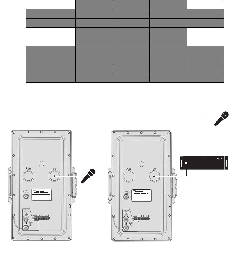
CONNECTING AUDIO
NOTE: Audio can only be installed using the MCC-AA multifunction cable.
The EW5301T supports one audio input. It supports both microphone and line input levels. Microphones have weaker signals that must be
amplified. Line inputs have stronger signals that have already been amplified.
The microphone input level is 5 mVp-p. The line input level is 1 Vp-p (0 dBV) nominal, 1.228 Vp-p (+4 dBu) maximum.
Set the switch from the WS5000 Endura workstation. By default, the switch is set to Line; refer to the Endura WS5000 Advanced System
Software Operation manual (C1624M).
NOTE: If the switch setting does not match your audio equipment, audio distortion problems may occur.
To implement audio, connect the audio inputs from the line input device or microphone, as indicated:
NOTE: Audio out is not supported at this time.
Figure 4 shows how to connect the microphone or line audio device to the audio wires.
Figure 4. Connecting an Audio Device
Wire Color MCC-PR MCC-PA MCC-AR MCC-AA
White/Blue Stripe PTZ TX- PTZ TX- Ground Alarm 0 Ground
Blue/White Stripe PTZ TX+ PTZ TX+ Relay N.C. Reserved
White/Orange Stripe PTZ RX- PTZ RX- Relay Common Audio In Ground
Orange/White Stripe PTZ RX+ PTZ RX+ Relay N.O. Audio In
White/Green Stripe Ground Alarms Ground Alarms Ground Alarm 0
Green/White Stripe Relay N.C. Alarm 0 Alarm 0 Relay N.C.
White/Brown Stripe Relay Common Alarm 1 Alarm 1 Relay Common
Brown/White Stripe Relay N.O. Alarm 2 Alarm 2 Relay N.O.
MODEL
FREQ
50/60HZ
Sample Text
AMPS
VOLTS
Sample Text
REV
Sample Text
MFG BY PELCO, CLOVIS, CA
Model
SN
MADE IN USA
MODEL
FREQ
50/60HZ
Sample Text
AMPS
VOLTS
Sample Text
REV
Sample Text
MFG BY PELCO, CLOVIS, CA
Model
SN
MADE IN USA
AUDIO PREAMP
MICROPHONE
INPUT
LINE
INPUT
C2677M (7/07) 17
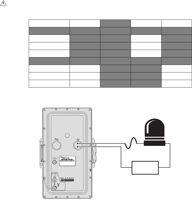
CONNECTING A RELAY DEVICE
NOTE: A relay device can be installed using the MCC-PR, MCC-AR, or MCC-AA multifunction cables.
The EW5301T has an output for triggering an external device. It supports both momentary and continuous relay operation.
You can operate the relay interactively, during an active connection, or automatically to coincide with certain events. Typical applications include
activating a door, gate or lock, or switching on lights or other electrical devices.
To implement a relay, connect the relay with its power source to the multifunction cable, as indicated:
Figure 5 shows how to wire the relay with its power source.
Figure 5. Connecting a Relay Device
WARNING: Do not exceed the maximum rating of 30 VDC, 1 A.
Wire Color MCC-PR MCC-PA MCC-AR MCC-AA
White/Blue Stripe PTZ TX- PTZ TX- Ground Alarm 0 Ground
Blue/White Stripe PTZ TX+ PTZ TX+ Relay N.C. Reserved
White/Orange Stripe PTZ RX- PTZ RX- Relay Common Audio In Ground
Orange/White Stripe PTZ RX+ PTZ RX+ Relay N.O. Audio In
White/Green Stripe Ground Alarms Ground Alarms Ground Alarm 0
Green/White Stripe Relay N.C. Alarm 0 Alarm 0 Relay N.C.
White/Brown Stripe Relay Common Alarm 1 Alarm 1 Relay Common
Brown/White Stripe Relay N.O. Alarm 2 Alarm 2 Relay N.O.
MODEL
FREQ
50/60HZ
Sample Text
AMPS
VOLTS
Sample Text
REV
Sample Text
MFG BY PELCO, CLOVIS, CA
Model
SN
MADE IN USA
NORMALLY
OPEN (NO)
COMMON (C) LOAD:
LIGHT/SIREN
POWER
MAX 30 VDC, 1 A
EXTERNAL
FUSE
18 C2677M (7/07)
CONNECTING ALARMS
The EW5301T offers three alarm inputs for external signaling devices, such as door contacts or motion detectors. Each encoder supports both
normally open and normally closed devices. Each encoder also supports both supervised and unsupervised alarms.
Once configured, an alarm input can invoke many different activities, including triggering a relay device, sending an alert to a security office,
changing the video recording settings, and storing pre-alarm video to an NVR5100 Series recorder or a DVR5300 Series recorder. You can connect
switches or contacts directly to the unit without a separate power supply.
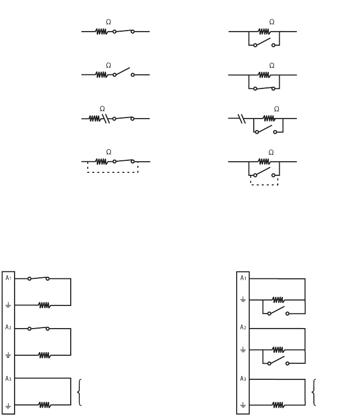
Supervised Alarms
When an alarm is configured as a supervised alarm, the EW5301T maintains a constant electrical current through the alarm circuit (3.3 VDC,
1 kohm). If the alarm circuit length changes, due to an electrical short or a bypass, the voltage fluctuates from its normal state. Therefore, the
unit triggers an alarm.
NOTE: Install the 1-kohm resistor as close to the switch as possible.
Figure 6 illustrates the alarm and no alarm conditions of a supervised alarm input. Whether the alarm is normally closed or normally open,
neither a cut nor a bypass can defeat these alarms.
Figure 6. Supervised Alarm Conditions
Figure 7 illustrates the wiring configuration for supervised alarm inputs.
Figure 7. Supervised Alarm Input Wiring
NORMALLY OPEN
NORMALLY CLOSED
ALARM
GND
+V
+V
ALARM
GND +V
+V
ALARM
GND
CUT
NO ALARMNO ALARM
GND
ALARM
GND
+V
+V
+V
+V
ALARM
GND
BYPASS
CUT
BYPASS
GND
ALARM
GND
1K
1K
1K
1K
1K
1K
1K
1K
NORMALLY CLOSED
UNUSED
INPUTS
MUST ALSO
BE WIRED
NORMALLY OPEN
UNUSED
INPUTS
MUST ALSO
BE WIRED
1 KΩ
1 KΩ
1 KΩ
1 KΩ
1 KΩ
1 KΩ
C2677M (7/07) 19
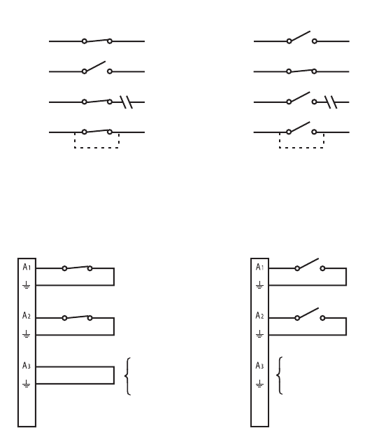
Unsupervised Alarms
When an alarm is configured as an unsupervised alarm, the EW5301T only triggers an alarm when the normal alarm state (open or closed)
changes.
Figure 8 illustrates the alarm and no alarm conditions of an unsupervised alarm input. A normally closed alarm input can be defeated with a
bypass. A normally open input can be defeated with a cut.
Figure 8. Unsupervised Alarm Conditions
Figure 9 illustrates the wiring configuration for unsupervised alarm inputs.
Figure 9. Unsupervised Alarm Input Wiring
NORMALLY OPEN
NORMALLY CLOSED
ALARM
GND
+V
+V
ALARM
GND +V
+V
NO ALARM
GND
ALARM
GND
+V
+V
+V
NO ALARM
GND
CUT
BYPASS
CUT
NO ALARM
GND
NO ALARM
GND
+V
BYPASS
ALARM
GND
NORMALLY CLOSED
UNUSED
INPUTS
MAY BE
SHORTED
NORMALLY OPEN
UNUSED
INPUTS
MUST BE LEFT
UNWIRED
20 C2677M (7/07)
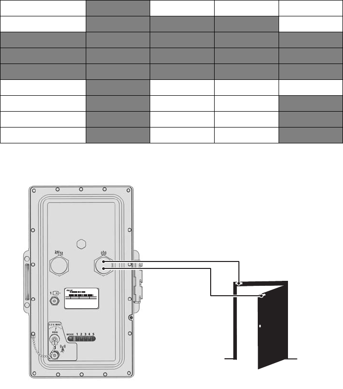
Alarm Connections
NOTE: Alarm inputs can be installed using the MCC-PA, MCC-AR, or MCC-AA multifunction cables.
To wire one or more alarms, connect the alarms to the multifunction cable, as indicated:
Figure 10 shows how to wire an alarm.
Figure 10. Connecting Alarms
Wire Color MCC-PR MCC-PA MCC-AR MCC-AA
White/Blue Stripe PTZ TX- PTZ TX- Ground Alarm 0 Ground
Blue/White Stripe PTZ TX+ PTZ TX+ Relay N.C. Reserved
White/Orange Stripe PTZ RX- PTZ RX- Relay Common Audio In Ground
Orange/White Stripe PTZ RX+ PTZ RX+ Relay N.O. Audio In
White/Green Stripe Ground Alarms Ground Alarms Ground Alarm 0
Green/White Stripe Relay N.C. Alarm 0 Alarm 0 Relay N.C.
White/Brown Stripe Relay Common Alarm 1 Alarm 1 Relay Common
Brown/White Stripe Relay N.O. Alarm 2 Alarm 2 Relay N.O.
MODEL
FREQ
50/60HZ
Sample Text
AMPS
VOLTS
Sample Text
REV
Sample Text
MFG BY PELCO, CLOVIS, CA
Model
SN
MADE IN USA
GROUND
ALARM
C2677M (7/07) 21
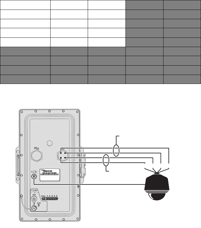
CONNECTING A PTZ DEVICE (PELCO P/PELCO D)
NOTE: PTZ devices can be installed using the MCC-PR or MCC-PA multifunction cables.
The EW5301T supports serial camera control using Pelco P or Pelco D (RS-422) for a PTZ device. You can connect only one serial PTZ device to a
video encoder. The default Pelco P/Pelco D device address is 1.
When the EW5301T receives a camera control command, it transmits that command to the PTZ device. In four-wire installations, the encoder
also receives data from the PTZ device, including camera status and alarm states. It then transmits that data to the command center.
To wire the PTZ device, connect the camera control leads to the multifunction cable, as indicated:
Figure 11 shows how to connect a Spectra dome to the multifunction cable.
Figure 11. Connecting a Spectra Dome
NOTE: When connecting a PTZ device to the EW5301T, connect the TX+ and TX- leads to the RX+ and RX- leads between the encoder and the
PTZ device.
Wire Color MCC-PR MCC-PA MCC-AR MCC-AA
White/Blue Stripe PTZ TX- PTZ TX- Ground Alarm 0 Ground
Blue/White Stripe PTZ TX+ PTZ TX+ Relay N.C. Reserved
White/Orange Stripe PTZ RX- PTZ RX- Relay Common Audio In Ground
Orange/White Stripe PTZ RX+ PTZ RX+ Relay N.O. Audio In
White/Green Stripe Ground Alarms Ground Alarms Ground Alarm 0
Green/White Stripe Relay N.C. Alarm 0 Alarm 0 Relay N.C.
White/Brown Stripe Relay Common Alarm 1 Alarm 1 Relay Common
Brown/White Stripe Relay N.O. Alarm 2 Alarm 2 Relay N.O.
MODEL
FREQ
50/60HZ
Sample Text
AMPS
VOLTS
Sample Text
REV
Sample Text
MFG BY PELCO, CLOVIS, CA
Model
SN
MADE IN USA
SPECTRA
TX-TX+ RX+RX-
VIDEO
TX-
TX+
RX+
RECEIVE
FROM SPECTRA
TRANSMIT
TO SPECTRA
RX-

22 C2677M (7/07)
By default, the encoder identifies any PTZ device as a fixed camera. You must configure the encoder before you can use the PTZ device; refer to
the Endura WS5000 Advanced System Software Operation manual (C1624M).
Refer to Table E when installing the PTZ device. It lists the serial port settings that the EW5301T supports.
Table E. Serial Port Options and Defaults
ANTENNA INSTALLATION
The EW5301T includes a planar antenna with integrated mount (ANTP-2-9 or ANTP-5-8). These are the only antennas that can be mounted
directly to the EW5301T. Any other antenna must be mounted separately.
Before installing either an integrated antenna or a separate antenna, consider the following:
• Make sure the elevation (height) and azimuth (horizontal angle) match at both wireless antenna sites. The units cannot connect unless the
antennas are pointing at each other. Antenna misalignment causes the most problems for most wireless installations.
• To limit signal loss, use the shortest cable possible. For every 3 ft (0.91 m) of length, antenna cables lose about 1.0 dB at 5.8 GHz or about
0.7 dB at 2.4 GHz.
If you are using the integrated antenna, you will mount it to the EW5301T as part of the installation procedure (refer to Unit Installation on
page 23).
To install a separate antenna, refer to the Endura Wireless Antenna Installation manual (C2698M).
BENCH SETUP (OPTIONAL)
The EW5301T is designed for easy installation and configuration. Most default settings are automatically configured, including network IP
addresses, DHCP server, encryption, wireless channels, and connection speed. However, in some cases, it will be necessary to configure the unit
on a workbench before installing it on its mount.
In some cases, it will be necessary to configure the unit on a workbench before installing it on its mount. You will need a service cable and a
bench power cable. Refer to the EW5301T Configuration manual (C2683M) and the service cable manual for more information.
Setting Options Default
Data rate
(bits per second)
110, 300, 1200, 2400, 4800, 9600, 19200, 38400,
57600, 115200, 230400
2400
Data bits 5, 6, 7, 8 8
Parity None, Odd, Even None
Stop bits 1, 2 1
C2677M (7/07) 23
Unit Installation
To install the EW5301T:
NOTE: If installing a separate antenna, skip to step 2 on page 24.
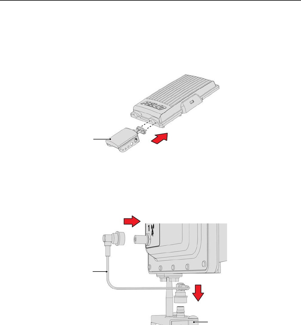
1. Attach the integrated antenna and antenna cable to the EW5301T.
a. Attach the integrated antenna to the EW5301T (refer to Figure 12). Do not tighten the bolts until you align the integrated antenna
(refer to Antenna Alignment on page 30).
Figure 12. Attaching the Integrated Antenna
NOTE: It is easier to attach the integrated antenna to the unit on the ground before carrying it up to the mount.
b. Remove the protective cover from the antenna connector on the rear panel.
c. Connect the antenna cable to the integrated antenna and the EW5301T (refer to Figure 13).
Figure 13. Connecting the Antenna Cable
d. Make sure both antenna connectors are fully seated. When inserting the connector, you should hear or feel two clicks.
ANTENNA
ANTENNA
CABLE
ANTENNA
24 C2677M (7/07)
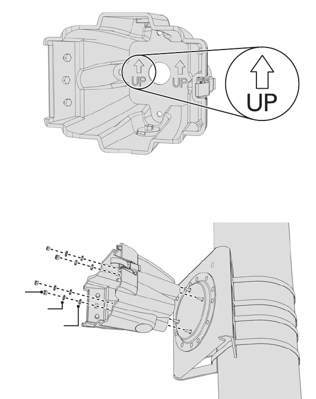
2. Install the mount (refer to the mount documentation for more information).
3. Orient the J-box so that the arrows and the word UP are pointed up (refer to Figure 14).
Figure 14. J-Box Orientation
4. Secure the J-box to the mount (refer to Figure 15).
Figure 15. Installing the J-Box (EWM shown)
NOTE: The nuts, washers, and lock washers shown in Figure 15 are for illustration only. They are not supplied with the EW5301T. Use the
actual hardware from the mount to secure the J-box to the mount.
WASHER
LOCK WASHER
NUT
C2677M (7/07) 25
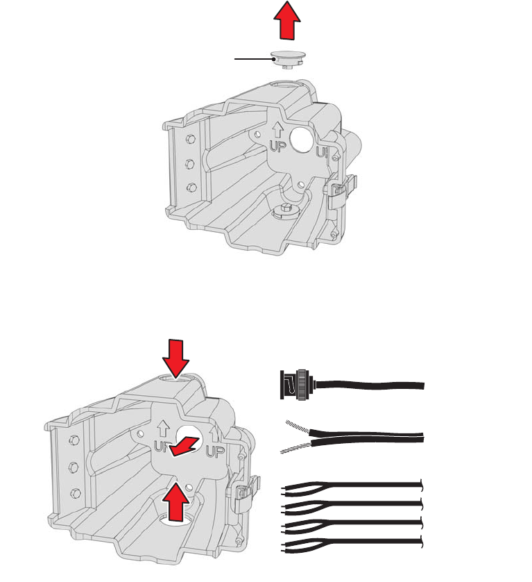
5. If using an auxiliary opening for cables: Remove the plug from the appropriate opening in the J-box (refer to Figure 16). Use a 7/16-inch
wrench.
Figure 16. Removing an Auxiliary Opening Plug
6. Route the power, video, and multifunction cables into the J-box through the top, back, or bottom opening (refer to Figure 17).
Figure 17. Routing Power, Video, and Multifunction Cables
PLUG
POWER (FROM SOURCE)
VIDEO (FROM CAMERA)
PTZ CONTROL,
ALARM, RELAY, AUDIO
(FROM DEVICES)

C2677M (7/07) 27
9. If using the multifunction cable: Wire the devices to the breakout box.
a. Install the breakout box.
b. Connect the leads to the breakout box from the specific devices: PTZ, alarm, relay, audio (refer to Figure 19 and Table F).
Figure 19. Wiring the Breakout Box
Table F. Breakout Box Wiring by Cable
Breakout
Box Pin
MCC-PR MCC-PA MCC-AR MCC-AA
8 PTZ TX- PTZ TX- Ground Ground
7 PTZ TX+ PTZ TX+ Relay N.C. Audio Out
6 PTZ RX- PTZ RX- Relay Common Ground
5 PTZ RX+ PTZ RX+ Relay N.O. Audio In
4 Ground Ground Ground Alarm 1
3 Relay N.C. Alarm 1 Alarm 1 Relay N.C.
2 Relay Common Alarm 2 Alarm 2 Relay Common
1 Relay N.O. Alarm 3 Alarm 3 Relay N.O.
1
2
3
4
8
7
6
5
28 C2677M (7/07)
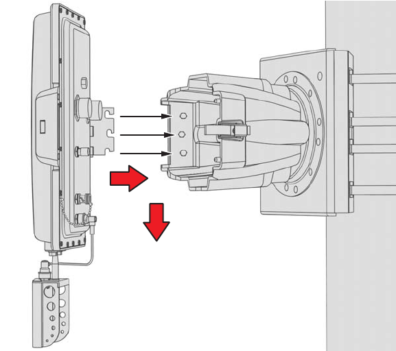
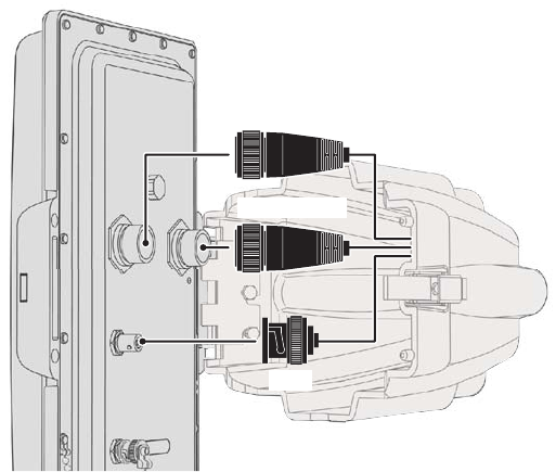
10. Connect all cables (refer to Figure 20):
NOTE: Be sure to fully seat each connector. Otherwise, environmental protection may fail, causing the unit to fail.
Figure 20. Connecting Cables to the EW5301T
a. If installing the multifunction cable: Connect the multifunction cable.
(1) Connect the RJ-45 connector on the multifunction cable to the breakout box.
(2) Remove the protective cover from the multifunction connector on the rear panel.
(3) Connect the multifunction cable to the multifunction connector on the rear panel. The connector is keyed and only attaches one
way, with the red arrow on top. Make sure you twist the connector all the way down.
b. Connect the video connector.
(1) Remove the protective cover from video input 1 on the rear panel.
(2) Connect the BNC from the camera system to video input 1.
c. Connect the power cable connector.
(1) Remove the protective cover from the power connector on the rear panel.
(2) Connect the power cable to the power connector on the rear panel. The connector is keyed and only attaches one way, with the
red arrow on top. Make sure you twist the connector all the way down.
d. If using the integrated antenna: Check the antenna connector to make sure it is fully seated. When inserting the connector, you should
hear or feel two clicks.
e. If using a separate antenna: Connect the antenna cable.
(1) Make sure the frequency of the antenna matches the frequency of the EW5301T. A label is attached to the antenna connector;
the blue label is for 2.4 GHz, the red label is for 5.8 GHz.
(2) Make sure the antenna cable is the correct length (refer to Optional Accessories on page 6 for antenna cables).
(3) Remove the protective cover from the antenna connector on the rear panel.
(4) Connect one end of the antenna cable to the antenna. Connect the other end of the cable to the connector on the rear panel.
Make sure both connectors are fully seated. When inserting the connector, you should hear or feel two clicks.to the antenna and
to the rear panel. Make sure both connectors are fully seated. When inserting the connector, you should hear or feel two clicks.
11. Close and latch the EW5301T to the J-box.
VIDEO
MULTIFUNCTION
POWER
C2677M (7/07) 29
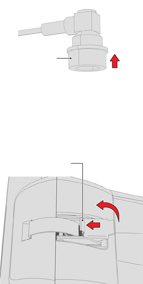
DISCONNECTING AN ANTENNA CABLE
The antenna cable connector is locking. To disconnect it, first pull the sleeve away from the device and hold it (refer to Figure 21). Then pull the
connector from the device.
Figure 21. Disconnecting an Antenna Cable Connector
OPENING THE J-BOX
The latch that secures the EW5301T includes a safety release.
To open the J-box (refer to Figure 22):
1. Press and hold the safety release.
2. Release the latch.
3. Open the J-box.
Figure 22. J-Box Safety Latch Release
SLEEVE
SAFETY LATCH
RELEASE
30 C2677M (7/07)
Antenna Alignment
To achieve the best results, the final step is to align the antenna on the EW5301T with the antenna on the access point (EW5001 or EW5002).
The Receiver Signal Strength Indicator (RSSI) port provides an easy way to help align the antenna for the best possible signal level.
RSSI is a function of transmission power, receiver sensitivity at a specific link speed, antenna alignment, and the noise floor. One way to improve
the RSSI is to use a lower link speed.
The EW5301T regularly calculates the RSSI value. Once calculated, it outputs this power level to the RSSI connector, where you can read it with
a digital voltmeter (DVM). The RSSI value ranges from 0 V to 3.3 V. When adjusting the antenna, get as close to 3.3 V as possible.
For this procedure, you will use the RSSI connector on the rear panel and a DVM with a BNC adapter.
To align the antenna:
1. Make sure the following indicators are solid green before proceeding:
• EW5301T: LED 1 and LED 2
• EW5001: LED 4
• EW5002: LED 4 or LED 5
2. Make sure the EW5001 or EW5002 is operational and configured as an access point.
3. Point the antenna toward the access point.
4. Set the scale on the DVM for 0 VDC to 6 VDC.
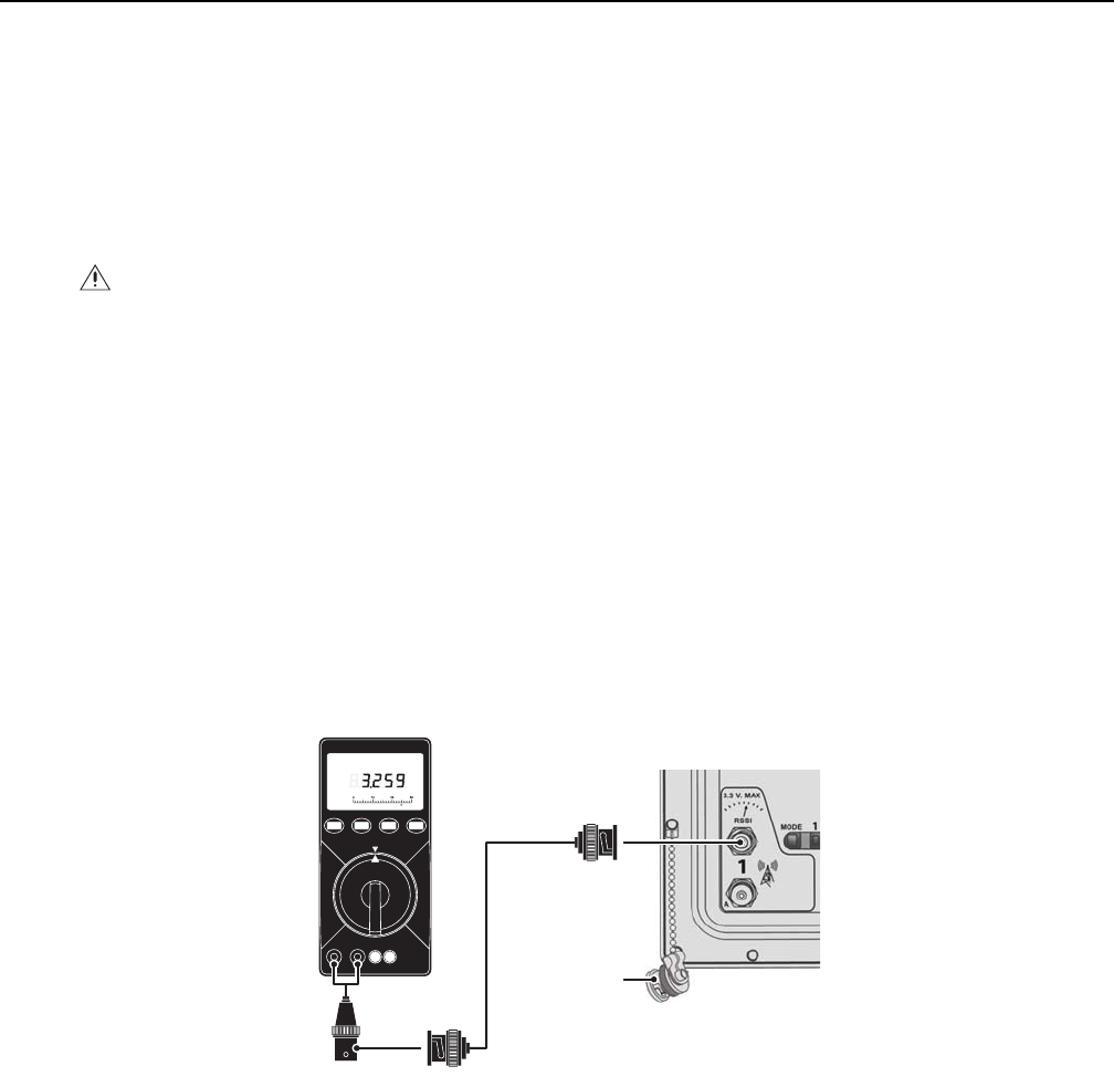
5. Uncap the RSSI connector on the EW5301T (refer to Figure 23).
NOTE: The cap is attached to the EW5301T; you will reinstall it later to protect the unit from weather damage.
Figure 23. Connecting a DVM to the EW5301T
6. Connect the DVM and a BNC adapter to the RSSI connector on the EW5301T.
7. Adjust the antenna to achieve the best signal strength. The target is 3.3 VDC.
8. Tighten the antenna mounting hardware.
9. Disconnect the DVM and BNC adapter from the RSSI connector on the EW5301T.
10. Reinstall the cap on the RSSI connector on the EW5301T.
NOTE: Do not skip this step; you must reinstall the cap to protect the unit from weather damage.
11. Optional: Realign the antenna on the access point.
NOTE: Only realign the antenna if distance, weather, obstructions, or other factors are affecting signal strength.
WARNING: Do not put your hand or other body part in front of a directional antenna during this procedure.
DIGITAL VOLTMETER
BNC ADAPTER
BNC CABLE
RSSI CONNECTOR
CAP
C2677M (7/07) 31
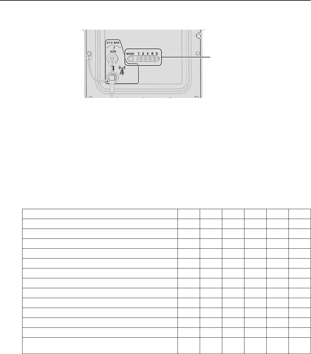
Indicators
The EW5301T has a set of six indicators on its rear panel (refer to Figure 24). These indicators show unit status during startup and normal
operation.
Figure 24. EW5301T Status Indicators
INDICATORS DURING STARTUP
During the startup sequence, the unit steps through a number of phases. The color of the MODE indicator shows the status of each phase:
Green The phase was completed successfully.
Amber The phase is in process. When this indicator is amber, the indicator for the phase will blink.
Red An error occurred that could not be corrected.
Table G shows the color and state of each indicator during startup.
Table G. Indicators During Startup
If the Endura network is in secure mode, LED 5 will keep blinking. As soon as you manually add or accept the EW5301T onto the Endura network
from a WS5000, LED 5 will stop blinking. Refer to the Endura WS5000 Advanced System Software Operation manual (C1624M) for more
information about secure mode.
Startup Phase MODE12345
Initializing boot loader. Off Off Off Off Off Off
Boot loader initialization successful. Amber Off Off Off Off Off
Initializing Linux operating system and unit hardware. Amber Blinking Off Off Off Off
Linux operating system and unit hardware initialization successful. Green On Off Off Off Off
Connecting to an EW5001 or EW5002 access point. Amber On Blinking Off Off Off
Connected to an access point. Green On On Off Off Off
Connecting to the Endura Wireless Resource Manager (EWRM). Amber On On Blinking Off Off
Connected to the EWRM. Green On On On Off Off
Receiving an IP address from the Endura DHCP server. Amber On On On Blinking Off
Connected to the Endura network; MODE indicator turns green. Green On On On On Off
Trying to connect to the SM5000 on the Endura network. Green On On On On Blinking
Unit is part of the Endura network. GreenOnOnOnOnBlinking
The Endura network is in secure mode and the unit has been
authenticated as a secure device.
GreenOnOnOnOnOn
STATUS
INDICATORS

32 C2677M (7/07)
INDICATORS DURING OPERATION
During operation, the indicators show unit status as well as status changes (refer to Table H).
Table H. Indicators During Operation
Status Change MODE 12345
Unit operating normally. Green On On On On On
Failure to renew unit IP address. Green On On On On Blinking
Unit removed from scheduler's polling-Q. GreenOnOnOnBlinkingOff
Unit disassociated. Green On On Blinking Off Off
Scanning. Green On Blinking Off Off Off

C2677M (7/07) 33
Configuration and Operation
The EW5301T is configured in two parts:
1. Configure the network and wireless communication settings; refer to the supplied EW5301T Configuration manual (C2683M).
2. Configure the actual EW5301T video encoder settings; refer to the Endura WS5000 Advanced System Software Operation manual
(C1624M).
Once configured, you can access the EW5301T video encoder in the same manner as other Endura video encoders. Refer to the Endura WS5000
Advanced System Software Operation manual (C1624M) for more information.

34 C2677M (7/07)
Troubleshooting
If the following instructions fail to solve your problem, contact Pelco Product Support at 1-800-289-9100 or 1-559-292-1981 for assistance.
Access the properties windows for the EW5301T video encoder on the WS5000 Endura workstation; refer to the Endura WS5000 Advanced
System Software Operation manual (C1624M). Then note the following before calling Pelco:
• Unit serial number: located on the Properties window and on the product label
• Unit firmware version: located on the Advanced Properties window, listed for the Encoder Device
NOTE: Do not try to repair the unit yourself. Opening it immediately voids any warranty. Leave maintenance and repairs to qualified technical
personnel. Exchange the defective unit and return it for repair.
Table I. Troubleshooting the EW5301T
Problem Possible Causes Suggested Remedy
No video transmission Power turned off Check that the MODE indicator is lit.
Faulty cable connections Check all leads, plugs, contacts, and connections.
Defective camera Connect local monitor and check camera function.
Defective encoder Check camera on a different encoder.
Network connectivity issues Contact your network administrator.
No audio transmission to receiver Faulty cable connection Check all leads, plugs, contacts, and connections.
Defective hardware Check functioning of all connected audio devices.
Connection in use by another receiver Wait until the connection is free and try again.
Cannot control PTZ cameras or
other devices
Faulty cable connection Check all cable connections and ensure all plugs are properly
plugged in.
Network connectivity issues Contact your network administrator.
Incorrect PTZ settings Change the camera settings on the WS5000 Endura workstation.
The unit is not ready for operation
after firmware upload
Voltage failure during programming of
update file
Replace the device and have it checked by Pelco.

C2677M (7/07) 35
Specifications
MODEL NUMBER
EW5301T-2 Network video server that encodes video, audio, and control data for wireless transmission; 2.4 GHz radio
EW5301T-5 Network video server that encodes video, audio, and control data for wireless transmission; 5.8 GHz radio
SUPPLIED ACCESSORIES
Power Cable with Connector 1
Integrated Antenna 1, either 2.4 GHz or 5.8 GHz
SYSTEM
Processor PowerPC® 405EP
Operating System Linux®
User Interface Remote operation from Endura Workstation or VCD5000
VIDEO/AUDIO
Video Standards NTSC/PAL/EIA/CCIR composite
Video Coding MPEG-4
Video Streams 2, simultaneous
Video Resolutions NTSC PAL
4CIF 704 x 480 704 x 576
2CIF 704 x 240 704 x 288
CIF 352 x 240 352 x 288
QCIF 176 x 120 176 x 144
Video Inputs/Connectors 1, BNC, 75 ohms, 1 Vp-p
Audio Encoding G.711 speech codec
Audio Bit Rate 64 kbps
Audio Levels
Line In 1 Vp-p (0 dBV) nominal, 1.228 Vp-p (+4 dBu) maximum, 10 kohms
Microphone 5 mVp-p, approximately 40 kohms
Audio Input Microphone or line in
PTZ CONTROL
PTZ Interface RS-422, video in
PTZ Protocols Pelco P/Pelco D (RS-422), Coaxitron
ALARMS/RELAYS
Alarm Inputs 3, programmable, 3.3 VDC, 1 kohms, triggered
Relay Output 1, form-C relay, 30 VDC, 1 A
VIDEO ACTIVITY DETECTION
Zones 3 plus background zone
Zone Types Any shape, user-definable in 16 x 16 pixel blocks
Sensitivity Adjustable
INDICATORS
MODE Green, amber, red
1-5 Green
36 C2677M (7/07)
RADIO FREQUENCY
Power Output 21 to 26 dBm (±1 dB)
Transmitting Frequency 2.412 – 2.462 GHz (ISM)
5.745 – 5.825 GHz (ISM)
Antenna Types and Gain Planar antenna, 2.4 GHz, 8.5 dBi gain, 75° x 60° beamwidth
Planar antenna, 5.8 GHz, 13.5 dBi gain, 40° x 35° beamwidth
Planar antenna, 5.8 GHz, 23.0 dBi gain, 9° x 9° beamwidth
Planar antenna, 5.8 GHz, 28.0 dBi gain, 4.5° x 4.5° beamwidth
Grid parabolic dish antenna, 2.4 GHz, 14.0 dBi gain, 21° x 14° beamwidth
Polarization Horizontal, vertical
Data Throughput Rate Up to 54 Mbps
POWER
Power Consumption 14 W, 48 BTU/H
Power Input 12 VDC ±10%
24 VAC ±10%
ENVIRONMENTAL
Operating Temperature -30° to 122°F (-34° to 50°C)
Storage Temperature -40° to 149°F (-40° to 65°C)
Operating Humidity 20% to 95%, noncondensing
Operating Altitude -50 ft to 10,000 ft (-16 m to 3,048 m)
PHYSICAL
Construction Cast aluminum
Finish White powder coat
Dimension (Without Antenna) 8.76" D x 8.66" W x 14.49" H
(22.25 x 22.00 x 36.80 cm)
Mounting Corner, pole, or parapet with options
(for outdoor use only)
Unit Weight (Without Antenna) 13.7 lb (6.21 kg)
OPTIONAL MOUNTING ACCESSORIES
ECM100 Esprit corner mount with center feedthrough hole
EPM Esprit pole mount with center feedthrough hole
CM100/CM400 Corner mount
PA402 Pole mount
PP100/PP400 Parapet mount
PP300L/PP301L Parapet corner mount
PP4348 Parapet rooftop mount
EA4348 Adapter plate for CM400, PA402, PP300L, PP301L, PP400, and PP4348
C2677M (7/07) 37
STANDARDS/ORGANIZATIONS
• Pelco is a member of the MPEG-4 Industry Forum
• Pelco is a member of the Universal Plug and Play (UPnP) Forum
• Pelco is a member of the Universal Serial Bus (USB) Implementers Forum
• Pelco is a contributor to the International Standards for Organization/Electrotechnical Commission (ISO/IEC) Joint Technical Committee 1
(JTC1), “Information Technology,” Subcommittee 29, Working Group 11
• Compliance, ISO/IEC 14496 standard (also known as MPEG-4)
• Compliant with International Telecommunication Union (ITU) Recommendation G.711, “Pulse Code Modulations (PCM) of Voice Frequencies”
(Design and product specifications subject to change without notice.)
38 C2677M (7/07)

PRODUCT WARRANTY AND RETURN INFORMATION
WARRANTY
Pelco will repair or replace, without charge, any merchandise proved defective in material or
workmanship for a period of one year after the date of shipment.
Exceptions to this warranty are as noted below:
• Five years on FR/FT/FS Series fiber optic products and TW3000 Series unshielded twisted
pair transmission products.
• Three years on Genex® Series products (multiplexers, server, and keyboard).
• Three years on Camclosure® and fixed camera models, except the CC3701H-2,
CC3701H-2X, CC3751H-2, CC3651H-2X, MC3651H-2, and MC3651H-2X camera models,
which have a five-year warranty.
• Three years on PMCL200/300/400 Series LCD monitors.
• Two years on standard motorized or fixed focal length lenses.
• Two years on Legacy®, CM6700/CM6800/CM9700 Series matrix, and DF5/DF8 Series fixed
dome products.
• Two years on Spectra®, Esprit®, ExSite™, and PS20 scanners, including when used in
continuous motion applications.
• Two years on Esprit® and WW5700 Series window wiper (excluding wiper blades).
• Two years (except lamp and color wheel) on Digital Light Processing (DLP®) displays.
The lamp and color wheel will be covered for a period of 90 days. The air filter is not
covered under warranty.
• Eighteen months on DX Series digital video recorders, NVR300 Series network video
recorders, and Endura™ Series distributed network-based video products.
• One year (except video heads) on video cassette recorders (VCRs). Video heads will be
covered for a period of six months.
• Six months on all pan and tilts, scanners or preset lenses used in continuous motion
applications (that is, preset scan, tour and auto scan modes).
Pelco will warrant all replacement parts and repairs for 90 days from the date of Pelco
shipment. All goods requiring warranty repair shall be sent freight prepaid to Pelco, Clovis,
California. Repairs made necessary by reason of misuse, alteration, normal wear, or accident
are not covered under this warranty.
Pelco assumes no risk and shall be subject to no liability for damages or loss resulting from
the specific use or application made of the Products. Pelco’s liability for any claim, whether
based on breach of contract, negligence, infringement of any rights of any party or product lia-
bility, relating to the Products shall not exceed the price paid by the Dealer to Pelco for such
Products. In no event will Pelco be liable for any special, incidental or consequential damages
(including loss of use, loss of profit and claims of third parties) however caused, whether by
the negligence of Pelco or otherwise.
The above warranty provides the Dealer with specific legal rights. The Dealer may also have
additional rights, which are subject to variation from state to state.
If a warranty repair is required, the Dealer must contact Pelco at (800) 289-9100 or
(559) 292-1981 to obtain a Repair Authorization number (RA), and provide the following
information:
1. Model and serial number
2. Date of shipment, P.O. number, Sales Order number, or Pelco invoice number
3. Details of the defect or problem
If there is a dispute regarding the warranty of a product which does not fall under the
warranty conditions stated above, please include a written explanation with the product when
returned.
Method of return shipment shall be the same or equal to the method by which the item was
received by Pelco.
RETURNS
In order to expedite parts returned to the factory for repair or credit, please call the factory at
(800) 289-9100 or (559) 292-1981 to obtain an authorization number (CA number if returned for
credit, and RA number if returned for repair).
All merchandise returned for credit may be subject to a 20% restocking and refurbishing
charge.
Goods returned for repair or credit should be clearly identified with the assigned CA or RA
number and freight should be prepaid. Ship to the appropriate address below.
If you are located within the continental U.S., Alaska, Hawaii or Puerto Rico, send goods to:
Service Department
Pelco
3500 Pelco Way
Clovis, CA 93612-5699
If you are located outside the continental U.S., Alaska, Hawaii or Puerto Rico and are
instructed to return goods to the USA, you may do one of the following:
If the goods are to be sent by a COURIER SERVICE, send the goods to:
Pelco
3500 Pelco Way
Clovis, CA 93612-5699 USA
The materials used in the manufacture of this document and its components are compliant to the requirements of Directive 2002/95/EC.
This equipment contains electrical or electronic components that must be recycled properly to comply with Directive 2002/96/EC of the European Union
regarding the disposal of waste electrical and electronic equipment (WEEE). Contact your local dealer for procedures for recycling this equipment.
REVISION HISTORY
Manual # Date Comments
C2677M 7/07 Original version.
Pelco, the Pelco logo, Spectra, Genex, Esprit, Camclosure, Coaxitron, and Legacy are registered trademarks of Pelco. © Copyright 2007, Pelco. All rights reserved.
ExSite, Endura, and EnduraView are trademarks of Pelco.
PowerPC is a registered trademark of International Business Machines Corporation.
Linux is a registered trademark of Linus Torvalds.
DLP is a registered trademark of Texas Instruments, Inc.